

Page 1
Symbol LS1203
Product Reference Guide
Page 2

Page 3

Symbol LS1203
Product Reference Guide
72E-73953-04
Revision A
August 2008
Page 4

ii Symbol LS1203 Product Reference Guide
© 2008 by Motorola, Inc. All rights reserved.
No part of this publication may be reproduced or used in any form, or by any electrical or mechanical means,
without permission in writing from Motorola. This includes electronic or mechanical means, such as
photocopying, recording, or information storage and retrieval systems. The material in this manual is subject to
change without notice.
The software is provided strictly on an “as i s” basis. All sof twar e, including firmware, furnished to the user is on
a licensed basis. Motorola grants to the user a non-transferab le and non-exclusive license to use each
software or firmware program delivered hereunder (licensed program). Except as noted below, such license
may not be assigned, sublicensed, or otherwise transferred by the user without prior written consent of
Motorola. No right to copy a licensed program in whole or in part is granted, except as permitted unde r
copyright law. The user shall not modify, merge, or incorporate any form or portion of a licensed program with
other program material, create a derivative work from a licensed program, or use a licensed program in a
network without written permission from Motorola. The user agrees to maintain Motorola’s copyright notice on
the licensed programs delivered hereunder, and to include the same on any authorized copies it makes, in
whole or in part. The user agrees not to deco mpile, disassemble, decode, or reverse engineer any licensed
program delivered to the user or any portion thereof.
Motorola reserves the right to make changes to any software or product to improve reliability, function, or
design.
Motorola does not assume any product liability arising out of, or in connection with, the application or use of
any product, circuit, or application described herein.
No license is granted, either expressly or by implication, estoppel, or otherwise under any Motorola, Inc.,
intellectual property rights. An implied license only exists for equipment, circuits, and subsystems contained in
Motorola products.
MOTOROLA and the Stylized M Logo and Symbol and the Symbol logo are registered in the US Patent &
Trademark Office. Bluetooth is a registered trademark of Bluetooth SIG. Microsoft, Windows and ActiveSync
are either registered trademarks or trademarks of Microsoft Corporation. All other product or service names
are the property of their respective owners.
Motorola, Inc.
One Motorola Plaza
Holtsville, New York 11742-1300
http://www.motorola.com/enterprisemobility
Patents
This product is covered by one or more of the patents listed on the website:
http://www.motorola.com/enterprisemobility/patents
Warranty
For the complete Motorola hardware product warranty statement, go to:
http://www.motorola.com/enterprisemobility/warranty
Page 5

Revision History
Changes to the original manual are listed below:
Change Date Description
-01 Rev A 1/2006 Initial release.
-02 Rev A 3/2006 Guide format updates. No content changes.
-03 Rev A 1/2008 Motorola rebranding, add hands free stand assembly instructions,
-04 Rev A 8/2008 Add HD model, change UCC/EAN-128 code type name to GS1-128.
iii
add new UPC/EAN supplemental options and Bookland ISBN format option.
Page 6

iv Symbol LS1203 Product Reference Guide
Page 7

Table of Contents
About This Guide
Introduction.................................................................................................................... xi
Configurations................................................................................................................ xi
Chapter Descriptions..................................................................................................... xi
Notational Conventions.................................................................................................. xii
Related Documents....................................................................................................... xiii
Service Information........................................................................................................ xiii
Chapter 1: Getting Started
Introduction ................................................................................................................... 1-1
Unpacking ..................................................................................................................... 1-2
Setting Up the Scanner ................................................................................................. 1-2
Installing the Interface Cable .................................................................................. 1-2
Removing the Interface Cable ................................................................................ 1-3
Connecting Power (if required) ............................................................................... 1-3
Assembling the Hands Free Stand ......................................................................... 1-4
Configuring the Scanner ......................................................................................... 1-5
Chapter 2: Scanning
Introduction ................................................................................................................... 2-1
Beeper Definitions ........................................................................................................ 2-2
LED Definitions ............................................................................................................. 2-3
Scanning ....................................................................................................................... 2-3
Aiming ..................................................................................................................... 2-4
Decode Zones .............................................................................................................. 2-6
Symbol LS1203-SR Standard Range ..................................................................... 2-6
Symbol LS1203-HD High Density ........................................................................... 2-7
Chapter 3: Maintenance & Technical Specifications
Introduction ................................................................................................................... 3-1
Maintenance ................................................................................................................. 3-1
Page 8

vi Symbol LS1203 Product Reference Guide
Troubleshooting ............................................................................................................ 3-2
Technical Specifications ............................................................................................... 3-5
Scanner Signal Descriptions ......................................................................................... 3-6
Chapter 4: User Preferences
Introduction ................................................................................................................... 4-1
Scanning Sequence Examples ..................................................................................... 4-1
Errors While Scanning .................................................................................................. 4-2
User Preferences Parameter Defaults .......................................................................... 4-2
User Preferences .......................................................................................................... 4-3
Default Parameters ................................................................................................. 4-3
Beeper Tone ........................................................................................................... 4-4
Beeper Volume ....................................................................................................... 4-4
Power Mode ............................................................................................................ 4-5
Scanning Mode ....................................................................................................... 4-5
Scan Line Width ...................................................................................................... 4-6
Laser On Time ........................................................................................................ 4-6
Beep After Good Decode ........................................................................................ 4-7
Transmit Code ID Character ................................................................................... 4-7
Prefix/Suffix Values ................................................................................................. 4-8
Scan Data Transmission Format ............................................................................ 4-8
FN1 Substitution Values ......................................................................................... 4-10
Transmit “No Read” Message ................................................................................. 4-10
Chapter 5: Keyboard Wedge Interface
Introduction ................................................................................................................... 5-1
Connecting a Keyboard Wedge Interface ..................................................................... 5-2
Keyboard Wedge Parameter Defaults .......................................................................... 5-3
Keyboard Wedge Host Parameters .............................................................................. 5-4
Keyboard Wedge Host Types ................................................................................. 5-4
Keyboard Wedge Country Types (Country Codes) ................................................ 5-5
Ignore Unknown Characters ................................................................................... 5-6
Keystroke Delay ...................................................................................................... 5-7
Intra-Keystroke Delay ............................................................................................. 5-7
Alternate Numeric Keypad Emulation ..................................................................... 5-8
Caps Lock On ......................................................................................................... 5-8
Caps Lock Override ................................................................................................ 5-9
Convert Wedge Data .............................................................................................. 5-9
Function Key Mapping ............................................................................................ 5-10
FN1 Substitution ..................................................................................................... 5-10
Send Make and Break ............................................................................................ 5-11
Keyboard Maps ....................................................................................................... 5-11
ASCII Character Set for Keyboard Wedge ................................................................... 5-12
Chapter 6: RS-232 Interface
Introduction ................................................................................................................... 6-1
Connecting an RS-232 Interface .................................................................................. 6-2
Page 9

Table of Contents vii
RS-232 Parameter Defaults .......................................................................................... 6-3
RS-232 Host Parameters .............................................................................................. 6-4
RS-232 Host Types ................................................................................................. 6-6
Baud Rate ............................................................................................................... 6-7
Parity ....................................................................................................................... 6-8
Stop Bit Select ........................................................................................................ 6-9
Data Bits (ASCII Format) ........................................................................................ 6-9
Check Receive Errors ............................................................................................. 6-10
Hardware Handshaking .......................................................................................... 6-10
Software Handshaking ............................................................................................ 6-12
Host Serial Response Time-out .............................................................................. 6-13
RTS Line State ........................................................................................................ 6-14
Beep on <BEL> ....................................................................................................... 6-14
Intercharacter Delay ................................................................................................ 6-15
Nixdorf Beep/LED Options ...................................................................................... 6-16
Ignore Unknown Characters ................................................................................... 6-16
ASCII Character Set for RS-232 ................................................................................... 6-17
Chapter 7: USB Interface
Introduction ................................................................................................................... 7-1
Connecting a USB Interface ......................................................................................... 7-2
USB Parameter Defaults .............................................................................................. 7-3
USB Host Parameters .................................................................................................. 7-4
USB Device Type .................................................................................................... 7-4
USB Country Keyboard Types (Country Codes) .................................................... 7-5
USB Keystroke Delay ............................................................................................. 7-7
USB CAPS Lock Override ...................................................................................... 7-7
USB Ignore Unknown Characters ........................................................................... 7-8
Emulate Keypad ...................................................................................................... 7-8
USB Keyboard FN 1 Substitution ............................................................................ 7-9
Function Key Mapping ............................................................................................ 7-9
Simulated Caps Lock .............................................................................................. 7-10
Convert Case .......................................................................................................... 7-10
ASCII Character Set for USB ........................................................................................ 7-11
Chapter 8: Symbologies
Introduction ................................................................................................................... 8-1
Scanning Sequence Examples ..................................................................................... 8-1
Errors While Scanning .................................................................................................. 8-2
Symbology Parameter Defaults .................................................................................... 8-2
UPC/EAN ...................................................................................................................... 8-5
Enable/Disable UPC-A/UPC-E ............................................................................... 8-5
Enable/Disable UPC-E1 .......................................................................................... 8-6
Enable/DisaGS1ble EAN-13/EAN-8 ....................................................................... 8-7
Enable/Disable Bookland EAN ............................................................................... 8-7
Decode UPC/EAN/JAN Supplementals .................................................................. 8-8
User-Programmable Supplementals ....................................................................... 8-11
UPC/EAN/JAN Supplemental Redundancy ............................................................ 8-11
Page 10

viii Symbol LS1203 Product Reference Guide
Transmit UPC-A Check Digit .................................................................................. 8-12
Transmit UPC-E Check Digit .................................................................................. 8-12
Transmit UPC-E1 Check Digit ................................................................................ 8-13
UPC-A Preamble .................................................................................................... 8-13
UPC-E Preamble .................................................................................................... 8-14
UPC-E1 Preamble .................................................................................................. 8-15
Convert UPC-E to UPC-A ....................................................................................... 8-15
Convert UPC-E1 to UPC-A ..................................................................................... 8-16
EAN-8/JAN-8 Extend .............................................................................................. 8-16
Bookland ISBN Format ........................................................................................... 8-17
UCC Coupon Extended Code ................................................................................. 8-18
Code 128 ...................................................................................................................... 8-18
Enable/Disable Code 128 ....................................................................................... 8-18
Enable/Disable GS1-128 (formerly UCC/EAN-128) ................................................ 8-19
Enable/Disable ISBT 128 ........................................................................................ 8-19
Code 39 ........................................................................................................................ 8-20
Enable/Disable Code 39 ......................................................................................... 8-20
Enable/Disable Trioptic Code 39 ............................................................................ 8-20
Convert Code 39 to Code 32 .................................................................................. 8-21
Code 32 Prefix ........................................................................................................ 8-21
Set Lengths for Code 39 ......................................................................................... 8-22
Code 39 Check Digit Verification ............................................................................ 8-23
Transmit Code 39 Check Digit ................................................................................ 8-23
Code 39 Full ASCII Conversion .............................................................................. 8-24
Code 39 Buffering (Scan & Store) .......................................................................... 8-24
Code 93 ........................................................................................................................ 8-27
Enable/Disable Code 93 ......................................................................................... 8-27
Set Lengths for Code 93 ......................................................................................... 8-27
Code 11 ........................................................................................................................ 8-28
Code 11 .................................................................................................................. 8-28
Set Lengths for Code 11 ......................................................................................... 8-29
Code 11 Check Digit Verification ............................................................................ 8-30
Transmit Code 11 Check Digits .............................................................................. 8-30
Interleaved 2 of 5 (ITF) ................................................................................................. 8-31
Enable/Disable Interleaved 2 of 5 ........................................................................... 8-31
Set Lengths for Interleaved 2 of 5 ........................................................................... 8-31
I 2 of 5 Check Digit Verification ............................................................................... 8-33
Transmit I 2 of 5 Check Digit ................................................................................... 8-33
Convert I 2 of 5 to EAN-13 ...................................................................................... 8-34
Discrete 2 of 5 (DTF) .................................................................................................... 8-34
Enable/Disable Discrete 2 of 5 ................................................................................ 8-34
Set Lengths for Discrete 2 of 5 ............................................................................... 8-35
Chinese 2 of 5 ............................................................................................................... 8-36
Enable/Disable Chinese 2 of 5 ................................................................................ 8-36
Codabar (NW - 7) ......................................................................................................... 8-36
Enable/Disable Codabar ......................................................................................... 8-36
Set Lengths for Codabar ......................................................................................... 8-37
CLSI Editing ............................................................................................................ 8-38
NOTIS Editing ......................................................................................................... 8-38
MSI ............................................................................................................................... 8-39
Page 11

Enable/Disable MSI ................................................................................................ 8-39
Set Lengths for MSI ................................................................................................ 8-39
MSI Check Digits .................................................................................................... 8-40
Transmit MSI Check Digit(s) ................................................................................... 8-41
MSI Check Digit Algorithm ...................................................................................... 8-41
GS1 DataBar (formerly RSS, Reduced Space Symbology) ......................................... 8-42
Convert GS1 DataBar to UPC/EAN ........................................................................ 8-43
Symbology - Specific Security Levels ........................................................................... 8-44
Redundancy Level .................................................................................................. 8-44
Security Level ......................................................................................................... 8-46
Bi-directional Redundancy ...................................................................................... 8-47
Symbology - Intercharacter Gap ................................................................................... 8-47
Chapter 9: 123Scan
Introduction ................................................................................................................... 9-1
Communication with 123Scan ...................................................................................... 9-1
123Scan Parameter ...................................................................................................... 9-1
Table of Contents ix
Appendix A: Standard Defaults
Appendix B: Programming Reference
Symbol Code Identifiers ................................................................................................ B-1
AIM Code Identifiers ..................................................................................................... B-2
Appendix C: Sample Bar Codes
Code 39 ........................................................................................................................ C-1
UPC/EAN ...................................................................................................................... C-1
UPC-A, 100% .......................................................................................................... C-1
EAN-13, 100% ........................................................................................................ C-1
Code 128 ...................................................................................................................... C-2
Interleaved 2 of 5 .......................................................................................................... C-2
GS1 DataBar ................................................................................................................ C-3
GS1 DataBar-14 ..................................................................................................... C-4
Appendix D: Numeric Bar Codes
Numeric Bar Codes ...................................................................................................... D-1
Cancel ........................................................................................................................... D-3
Appendix E: ASCII Character Sets
Index
Page 12

x Symbol LS1203 Product Reference Guide
Page 13

About This Guide
Introduction
The Symbol LS1203 Product Refere nce Guide provides ge neral instr uctions for se tting up, o peratin g, maint aining,
and troubleshooting the Symbol LS1203 scanner.
Configurations
This guide includes the following configurations:
•
Symbol LS1203-SR - Standard range scanning
•
Symbol LS1203-HD - High density scanning
Chapter Descriptions
Topics covered in this guide are as follows:
•
Chapter 1, Getting Started provides a product overview, unpacking instructions, and cable connection
information.
•
Chapter 2, Scanning describes part s of the scanne r , b eeper and LED definitions, and h ow to use the scanner
in triggered and Auto-Scan
•
Chapter 3, Maintenance & Technical Specifications provides information on how to care for the scanner,
troubleshooting, and technical specifications.
•
Chapter 4, User Preferences includes programming bar codes for selecting user preference features for the
scanner and commonly used bar codes to customize how the data is transmitted to the host device.
•
Chapter 5, Keyboard Wedge Interface provides information for setting up the sc an ne r fo r Keyb o ar d Wedge
operation.
•
Chapter 6, RS-232 Interface provides information for setting up the scanner for RS-232 operation.
•
Chapter 7, USB Interface provides information for setting up the scanner for USB operation.
TM
modes.
Page 14
xii Symbol LS1203 Product Reference Guide
•
Chapter 8, Symbologies describes all symbology features and provides the programming bar codes
necessary for selecting these features for the scanner.
•
Chapter 9, 123Scan (PC based scanner configuration tool) provides the bar code that must be scanned to
communicate with the 123Scan program.
•
Appendix A, Standard Defaults provides a table of all host devices and miscellaneous scanner defaults.
•
Appendix B, Programming Reference provides a table of AIM code identifiers, ASCII character conversions,
and keyboard maps.
•
Appendix C, Sample Bar Codes includes sample bar codes.
•
Appendix D, Numeric Bar Codes includes the numeric bar codes to scan for parameters requiring specific
numeric values.
•
Appendix E, ASCII Character Sets provides ASCII character value tables.
Notational Conventions
•
Italics are used to highlight chapters and sections in this and related documents
•
Bold text is used to highlight the following:
• Key names on a keypad.
•
bullets (•) indicate:
• Action items
• Lists of alternatives
• Lists of required steps that are not necessarily sequential
•
Sequential lists (e.g., those that describe step-by-s te p pr oc ed ur e s) ap pe a r as nu m be re d lists.
•
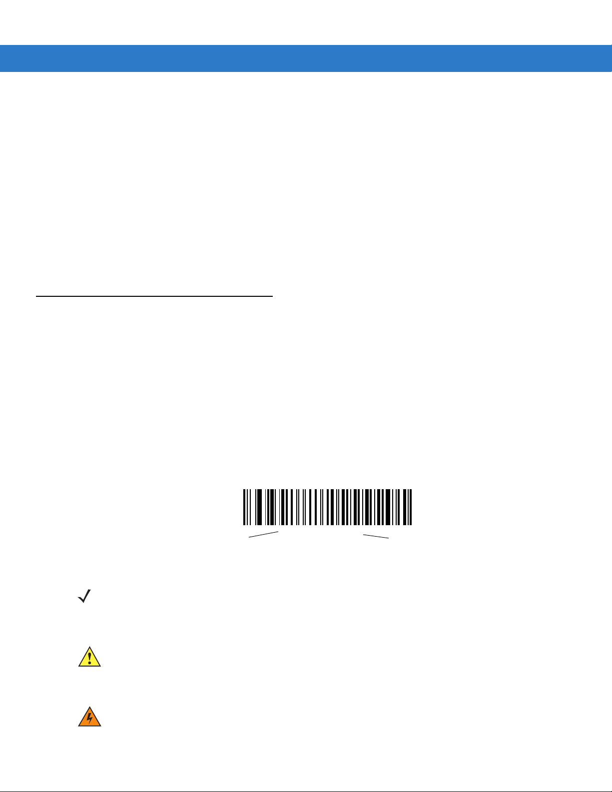
Throughout the programming bar code menus, asterisks (*) are used to denote default parameter settings.
* Indicates Default
NOTE This symbol indicates something of special interest or importance to the reader. Failure to read the note
will not result in physical harm to the reader, equipment or data.
*Baud Rate 9600
Feature/Option
CAUTION This symbol indicates that if this information is ignored, the possibility of data or material damage may
occur.
WARNING! This symbol indicates that if this information is ignored the possibility that serious personal
injury may occur.
Page 15

Related Documents
The Symbol LS1203 Quick Reference Guide (p/n 72-73954-xx) provides general information to help the user get
started with the scanner. It includes basic operation instructions and start up bar codes.
For the latest version of this guide and all guides, go to: http://www.motorola.com/enterprisemobility/manuals.
Service Information
If you have a problem with your equipment, contact Motorola Enterprise Mobility Support for your region. Contact
information is available at: http://www.motorola.com/enterprisemobility/contactsupport.
When contacting Enterprise Mobility Support, please have the following information available:
•
Serial number of the unit
•
Model number or product name
•
Software type and version number.
About This Guide xiii
Motorola responds to calls by E-mail, telephone or fax within the time limits set forth in support agreements.
If your problem cannot be solved by Motorola Enterprise Mobility Support, you may need to return your equipment
for servicing and will be given specific directions. Motorola is not responsible for any damages incurred during
shipment if the approved shipping container is not used. Shipping the units improperly can possibly void the
warranty.
If you purchased your Enterprise Mobility business product from a Motorola business partner, contact that business
partner for support.
Page 16

xiv Symbol LS1203 Product Reference Guide
Page 17

Chapter 1 Getting Started
Introduction
The scanner combines excellent scanning performance and advanced ergonomics to provide the best value in a
lightweight laser scanner. Whether used in triggered mode or Auto-Scan
ease of use for extended periods of time.
NOTE The scanner does not support PDF417 bar codes and its variants.
Figure 1-1
This scanner supports the following interfaces:
LS1203 Scanner
TM
mode, the scanner ensures comfort a nd
•
Keyboard Wedge connection to a host. The host interprets scanned data as keystrokes. This interface
supports the following international keyboards (for Windows
French, French Canadian, Spanish, Italian, Swedish, UK English, Portuguese-Brazilian, and Japanese.
•
Stan dard RS-232 connection to a host. Scan bar code menus to set up pr oper communication o f the scanner
with the host.
•
USB connection to a host. The scanner autodetects a USB host and defaults to the HID keyboard interface
type. Select other USB interface types by scanning prog ramming bar code menu s.This interface support s the
®
environment): North America, German,
Page 18
1 - 2 Symbol LS1203 Product Reference Guide
following international keyboards (for Windows® environment): North America, German, French, French
Canadian, Spanish, Italian, Swedish, UK English, Portuguese-Brazilian, and Japanese.
Unpacking
Remove the scanner from its packing and inspect it for damage. If the scanner was damaged in transit, call
Motorola Enterprise Mobility Support. See page xiii for contact information. KEEP THE PACKING. It is the
approved shipping container and should be used if the equipment ever needs to be return for se rvicing.
Setting Up the Scanner
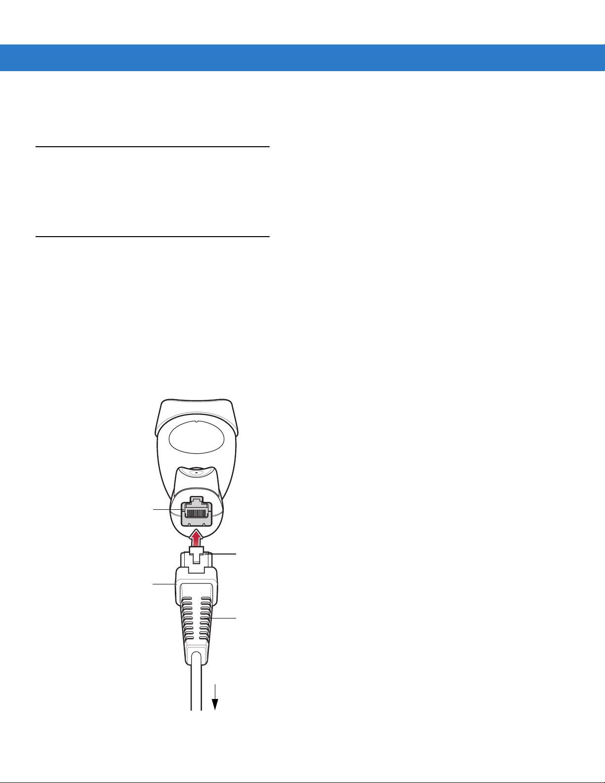
Installing the Interface Cable
To conne ct th e inte r fac e ca ble :
1. Insert the interface cable’s modular connector clip into the cable interface port on the bottom of the scanner
handle. (See Figure 1-2.)
2. Gently tug the cable to ensure the connector is properly secured.
3. Connect the other end of the interface cable to the host. (See the specific host chapter for information on host
connections.)
Cable interface
port
Interface cable modular
connector clip
Interface cable
modular connector
Interface cable
strain relief
Figure 1-2
To host
Installing the Cable
Page 19
Getting Started 1 - 3
NOTE Different cables are required for different hosts. The connectors illustrated in each host chapter are
examples only. Actual connectors may be different than those illustrated, but the steps to connect the
scanner remain the same.
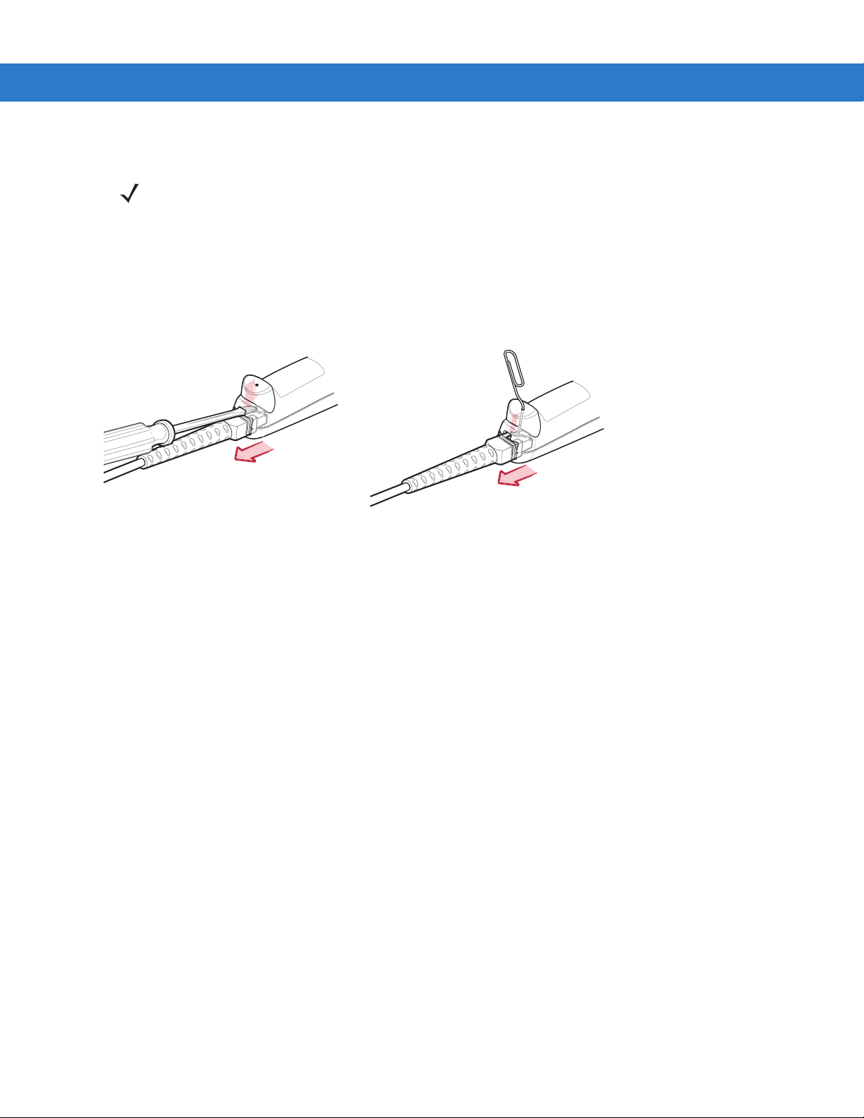
Removing the Interface Cable
To remove the interface cable:
1. Unplug the installed cable mod ular connector by depressing the connector clip with the tip of a screwdriver, or
a paper clip as shown in Figure 1-3.
Figure 1-3
2. Carefully slide out the cable.
3. Follow the steps for Installing the Interface Cable on page 1-2 to connect a new cable.
Removing the Interface Cable
Connecting Power (if required)
If the host does not provide power to the scanner, an external power connection to the scanner is required. To
connect power:
1. Connect the interface cable to the bottom of the scanner, as described in Installing the Interface Cable on page
1-2.
2. Connect the other end of the interface cable to the host (refer to the host manual to locate the correct port).
3. Plug the power supply into the power jack on the interface cable. Plug the other end of the power supp ly into
an AC outlet.
Page 20

1 - 4 Symbol LS1203 Product Reference Guide
Assembling the Hands Free Stand
1. Unscrew the wingnut from the bottom of the flexible neck.
2. Fit the bottom of the neck piece into the opening on the top of the stand base. When positioned correctly, the
flat areas of the neck piece fit into place in the stand base opening.
3. Tighten the wingnut underneath the base to secure the cup and neck piece to the base.
4. Bend the neck to the desired position for scanning.
Auto-scan bar code
(under cup)
One piece scanner “cup”
with flexible neck.
Flat areas
Stand base
Wingnut
Figure 1-4
Hands Free Stand Parts
Set Auto-scan Mode
To enable hands free scanning, scan the Auto-scan Mode bar code on the back of the cup to set the scanner to
auto-scan mode.
Page 21

Getting Started 1 - 5
Mount Stand (Optional)
Attach the base of the scanner stand to a flat surface using two screws or double-sided tape.
NOTE Screws and double-sided tape are not provided.
Two screw-mount holes
Rectangular tape holders (3 places)
(dimensions = 1” x 2”)
Figure 1-5
Scanner Mount Stand
Screw Mount
1. Position the assembled base on a flat surface.
2. Screw one #10 wood screw into each screw-mount hole until the base of the stand is secure.
Tape Mount
1. Peel the paper liner off one side of each piece of tape and place the sticky surface over each of the three
rectangular tape holders.
2. Peel the paper liner off the exposed sides of each piece of tape and press the stand on a flat surface until it is
secure.
Configuring the Scanner
To configure the scanner, use the bar codes included in this manual, or the 123Scan configuration program.
See Chapter 4, User Preferences and Chapter 8, Symbologies for information about programming the scanner
using bar code menus. Also see each host-specific chapter to set up a connection to a specific host type.
See Chapter 9, 123Scan to configure the scanner using this configuration program. A help file is available in the
program.
Page 22

1 - 6 Symbol LS1203 Product Reference Guide
Page 23

Chapter 2 Scanning
Introduction
This chapter provides beeper and LED definitions, techniqu es involved in scanning bar codes, general instructions
and tips about scanning, and decode zone diagrams.
LED
Scan
Window
Figure 2-1
Trigger
Button
Parts
Page 24

2 - 2 Symbol LS1203 Product Reference Guide
Beeper Definitions
The scanner issues different beep sequences and patterns to indicate status. Table 2-1 defines beep sequences
that occur during both normal scanning and while programming the scanner.
Table 2-1
Standard Use
Low/medium/high beeps
Short high beeps A bar code symbol was decoded (if decode beeper is
4 long low beeps A transmission error was detected in a scanned symbol. The
5 low beeps Conversion or format error.
Low/high/low beeps Advanced Data Formatting (ADF) transmit error. (For
High/high/high/low beeps RS-232 receive error.
Parameter Menu Scanning
Short high beeps Correct entry scanned or correct menu sequence performed.
Low/high beeps Input error, incorrect bar code or “Cancel” scanned, wrong
Beeper Definitions
Beeper Sequence Indication
Power up.
enabled).
data is ignored. This occurs if a unit is not properly
configured. Check option setting.
information about ADF programming, refer to th e Ad vanced
Data Formatting Programmer Guide, p/n 72-69680-xx.)
entry, incorrect bar code programming seque nce; rema in i n
program mode.
High/low beeps Keyboard parameter selected. Enter value using bar code
keypad.
High/low/high/low beeps Successful program exit with change in the parameter
setting.
Low/high/low/high beeps Out of host parameter storage space. Scan Default
Parameters on page 4-3.
Code 39 Buffering
High/low beeps New Code 39 data was entered into the buffer.
3 Beeps - long high beeps Code 39 buffer is full.
Low/high/low beeps The Code 39 buffer was erased or there was an attempt to
clear or transmit an empty buffer.
Low/high beeps A successful transmission of buffered data.
Page 25
Scanning 2 - 3
Table 2-1
Host Specific
USB only
RS-232 only
Beeper Definitions (Continued)
4 short high beeps Scanner has not completed initialization. Wait several
Scanner gives a power-up beep after
scanning a USB Device Type.
This power-up beep occurs more than once. The USB bus may put the scanner in a state where power to
1 short high beep A <BEL> character is received and Beep on <BEL> is
LED Definitions
In addition to beeper sequences, the scanner communicates with the user using a two-color LED display. Table 2-2
defines LED colors that display during scanning.
Beeper Sequence Indication
seconds and scan again.
Communication with the bus must be established befo re the
scanner can operate at the highest power level.
the scanner is cycled on and off more than once. This is
normal and usually happens when the host cold boots.
enabled.
Table 2-2
Off No power is applied to the scanner, or the scanner is on and ready to scan.
Green A bar code was successfully decoded.
Red A data transmission error or scanner malfunction occurred.
Scanning
The scanner can operate in two scanning modes: triggered mode and Auto-ScanTM mode. In triggered mode the
trigger button must be pressed to emit the scanner laser in order to a scan bar code. In Auto-Scan
scanner laser is in constant on state and no trigger button press is required to scan a bar code.
To toggle between scanning modes, scan Triggered/Auto-Scan
•
•
Standard LED Definitions
LED Indication
TM
mode the
TM
on page 4-5.
If the scanner is in triggered mode, scan Triggered/Auto-ScanTM on page 4-5 to switch to Auto-ScanTM
mode.
If the scanner is in Auto-ScanTM mode, scan Triggered/Auto-ScanTM on page 4-5 to switch to triggered
mode.
NOTE When the scanner is not used for an extended period of time in Auto-Scan
mode. To wake the scanner, press the trigger button.
TM
mode, it enters sleep
Page 26
2 - 4 Symbol LS1203 Product Reference Guide
To scan a bar code:
1. Install and program the scanner (see Setting Up the Scanner on page 1-2). For assistance, contact the local
supplier or Motorola Enterprise Mobility Support on page xiii.
2. Ensure all connections are secure. (See the host chapter for the scanner.)
3. Aim the scanner at the bar code.
4. If the scanner is in triggered mode, press the trigger button. (In Auto-Scan
TM
mode, no trigger button press is
required. The scanner laser is in constant on mode.)
Triggered Mode Auto-ScanTM Mode
Figure 2-2
5. Upon successful decode, the scanner beeps and the LED turns green. (For more information about beeper
Scanning - Triggered and Auto-ScanTM Modes
and LED definitions, see Table 2-1 and Table 2-2.)
NOTE Scan line lengths vary depending on the scan line width selected (see Scan Line Width on page 4-6). A
full scan line width is the default. The medium scan line width is useful for scanning menus or pick-lis ts.
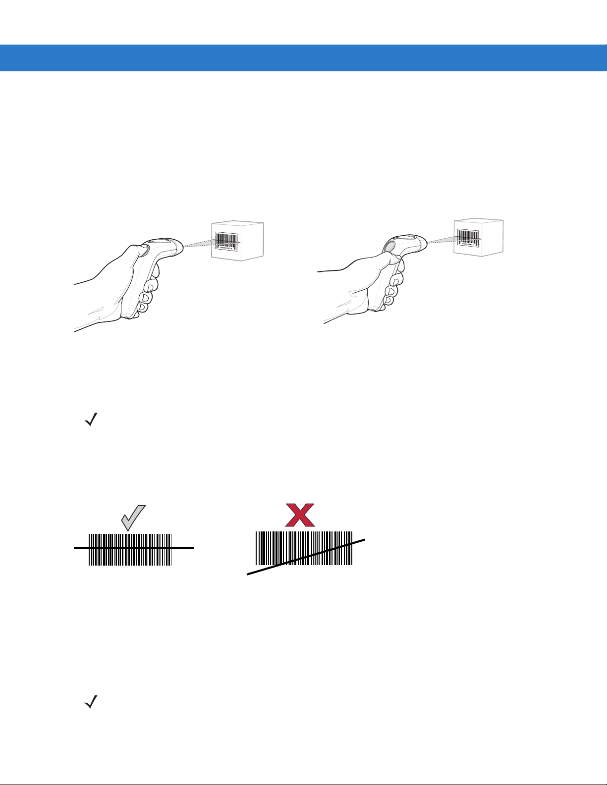
Aiming
On a typical UPC 100% bar code symbol, hold the scanner between contact and 7 inches from the symbol (see
Decode Zones on page 2-6). Ensure the scan line crosses every bar and space of the symbol.
Figure 2-3
012345
Acceptable and Incorrect Aiming
012345
The scan line is smaller when the scanner is closer to the symbol and larger when it is farther from the symbol.
Scan symbols with smaller bars or elements ( mil size) closer to the sca nner and those with larg er bars or element s
(mil size) farther from the scanner.
Do not hold the scanner directly over the bar code. Laser light reflecting directly back into the scanner from the bar
code is known as specular reflection. Specular reflection can make decoding difficult.
NOTE Scan line lengths vary depending on the scan line width selected. A full scan line width is the default. The
medium scan line width is useful for scanning menus or pick-lists.
For more information about scan line widths, see page 4-6.
Page 27
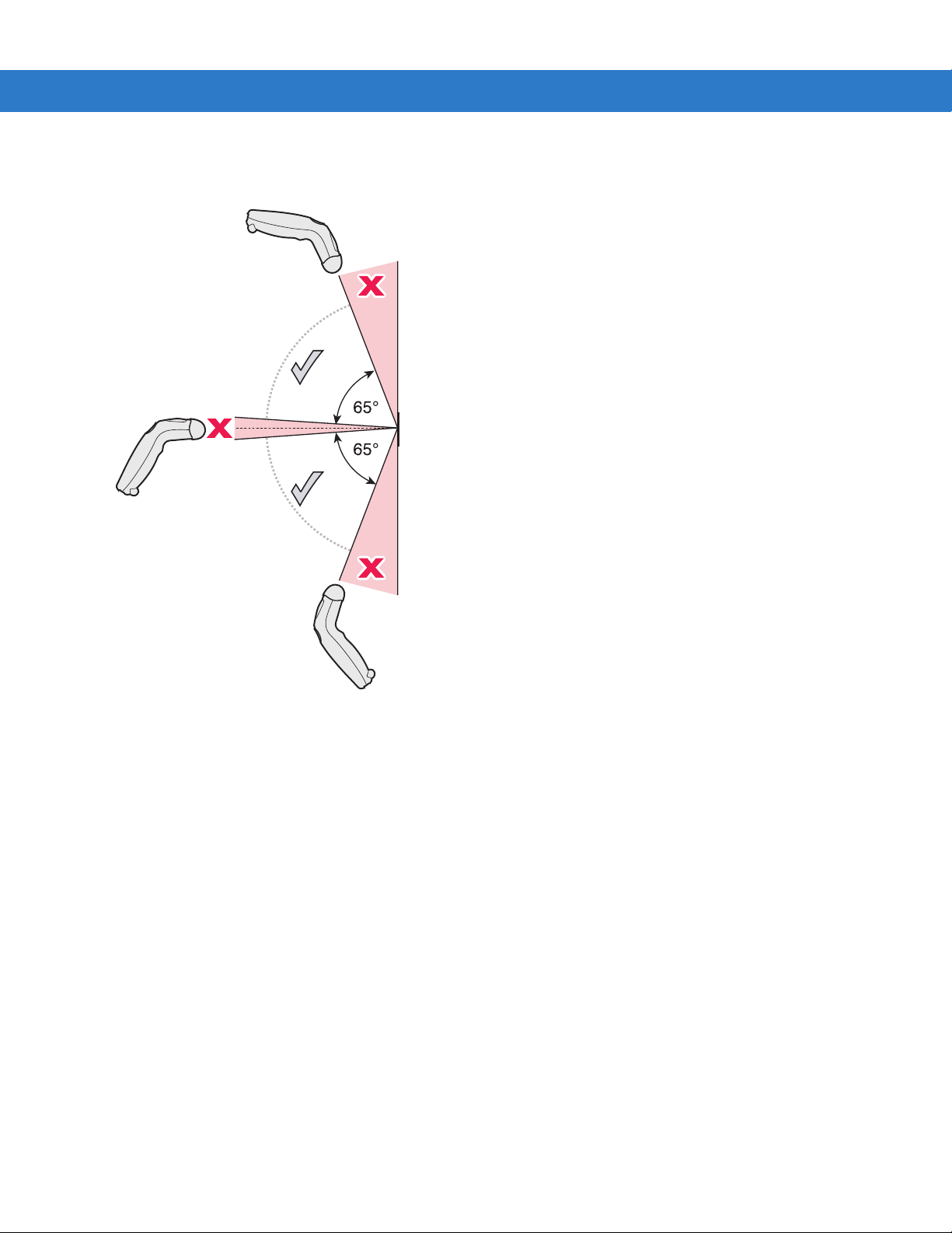
Scanning 2 - 5
The scanner can be tilted up to 65° forward or back and achieve a successful decode ( Figure 2-4). Sim ple practice
quickly shows what tolerances to work within.
Figure 2-4
Maximum Tilt Angles and Dead Zone
Page 28
2 - 6 Symbol LS1203 Product Reference Guide
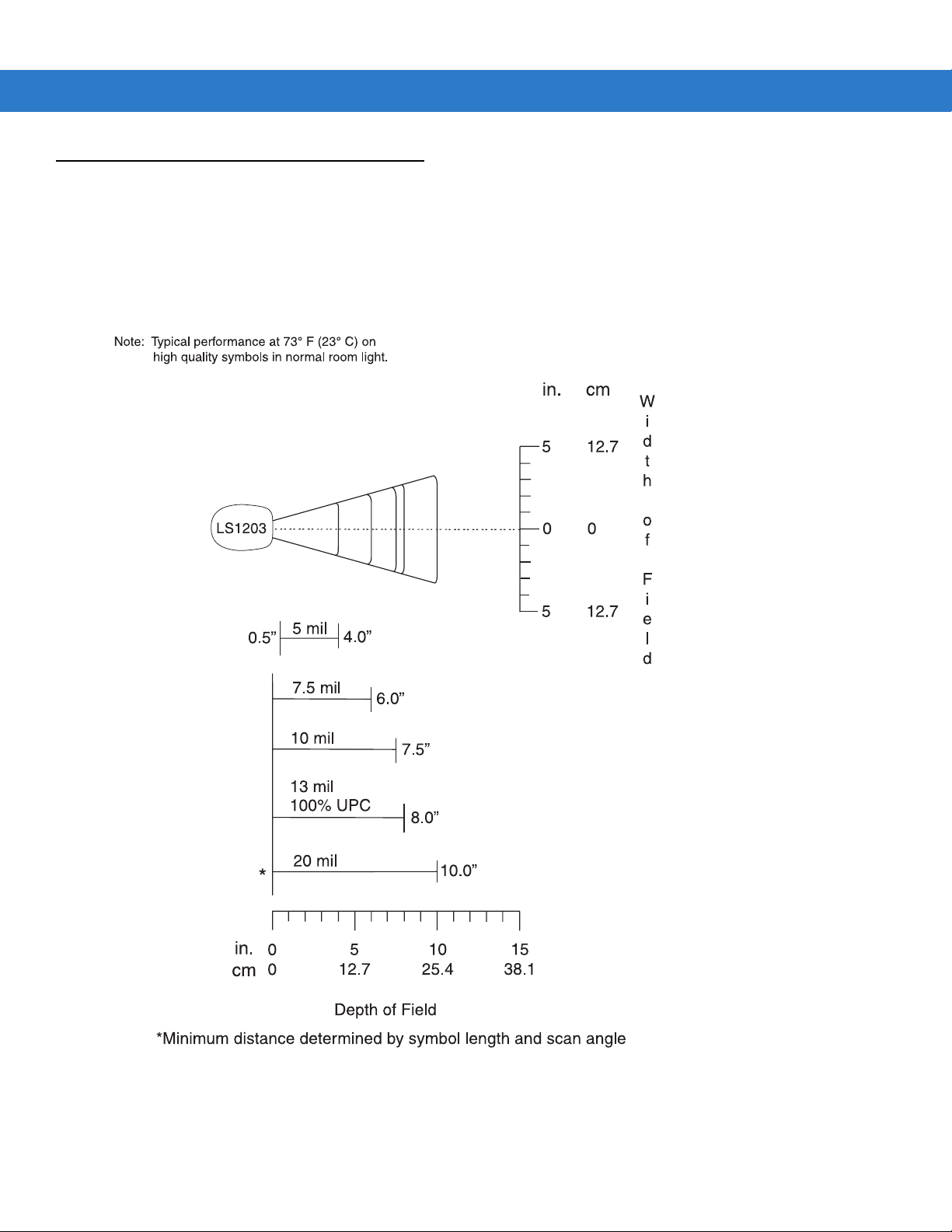
Decode Zones
Symbol LS1203-SR Standard Range
Figure 2-5
Symbol LS1203-SR St andard Range Decode Zone
Page 29

Symbol LS1203-HD High Density
Scanning 2 - 7
Note: Typical performance at 73° F (23° C) on
high quality symbols in normal room light.
LS1203-HD
3 mil
1.5”
5 mil
7.5 mil
10 mil
3.75”
4.5”
5.25”
in. cm
6.352.5
00
6.352.5
W
i
d
t
h
o
f
F
i
e
l
d
in.
cm
13 mil 100% UPC
*
0
0
20 mil
2.5
6.35
5
12.7
5.25”
6.63”
7.5
19.1
Depth of Field
*Minimum distance determined by symbol length and scan angle
Figure 2-6
Symbol LS1203-HD High Density Decode Zone
Page 30

2 - 8 Symbol LS1203 Product Reference Guide
Page 31

Chapter 3 Maintenance & Technical
Specifications
Introduction
This chapter provides suggested scanner maintenance, troubleshooting, technical specifications, and signal
descriptions (pinouts).
Maintenance
Cleaning the exit window is the only maintenance required. A dirty window may affect scanning ability.
•
Do not allow any abrasive material to touch the window
•
Remove any dirt particles with a damp cloth
•
Wipe the window using a tissue moistened with ammonia/water
•
Do not spray water or other cleaning liquids directly into the window.
Page 32

3 - 2 Symbol LS1203 Product Reference Guide
Troubleshooting
Table 3-1
Beeper Indications (Also see
The scanner emits frequent
beeps. (USB host interface only.)
Scanner emits low/high/low
beeps.
Scanner emits low/high beeps. Input error , incorrect bar code or
Scanner emits low/high/low
beeps.
Troubleshooting
Problem Possible Causes Possible Solutions
Beeper Definitions on page 2-2
The USB bus may put the scanner in
a state where power to the scanner is
cycled on and off more than once.
ADF transmit error. Refer to the Advanced Data
Invalid ADF rule is detected. Refer to the Advanced Data
Cancel bar code was scanned.
The Code 39 buffer was erased or
there was an attempt to clear or
transmit an empty buffer.
)
This is normal and usually happens
when the host cold boots.
Formatting Programmer’s Guide, p/n
72-69680-xx, for information about
ADF programming.
Formatting Programmer’s Guide, p/n
72-69680-xx, for information about
ADF programming.
Scan the correct numeric bar codes
within range for the parameter
programmed.
Normal when scanning the Code 39
Buffering Clear Buffer bar code or
upon attempt to transmit an empty
Code 39 buffer.
Scanner emits low/high/low/high
beeps.
Scanner emits high/low beeps. The scanner is buffering Code 39
Scanner emits high/high/high/low
beeps.
Scanner emits four long low
beeps.
Scanner emits four short high
beeps (USB only).
Scanner emits a short
low/high/low/high beep sequence
while it is being programmed.
Out of host parameter storage
space.
Out of memory for ADF rules. Reduce the number of ADF rules or
data.
RS-232 receive error. Normal during host reset. Otherw is e,
A transmission error was detected in
a scanned symbol. The data is
ignored.
Scanner has not completed
initialization.
Out of ADF parameter storage
space.
Scan Default Parameters on page
4-3.
the number of steps in the ADF rules.
Normal.
set the scanner's RS-232 parity to
match the host setting.
This occurs if a unit is not properly
configured. Check option setting.
Wait several seconds and scan again.
Erase all rules and re-program with
shorter rules.
Page 33

Maintenance & Technical Specifications 3 - 3
Table 3-1
Decoding Bar Codes
Scanner emits the laser, but does
not decode the bar code.
Scanner decodes bar code, but
does not transmit the data to the
host.
Troubleshooting (Continued)
Problem Possible Causes Possible Solutions
Scanner is not programmed for the
correct bar code type.
Bar code symbol is unreadable. Scan test symbols of the same bar
Distance between scanner and bar
code is incorrect.
The scan line is not crossing every
bar and space of the symbol.
Scanner is not programmed for the
correct host type.
Interface cable is loose. Check for loose cable connection and
Program the scanner to read that type
of bar code. See Chapter 8,
Symbologies.
code type to determine if the bar code
is defaced.
Move the scanner closer to or further
from the bar code. See Decode Zones
on page 2-6.
Move the symbol until the scan line is
within the acceptable aiming pattern.
See Figure 2-3 on page 2-4.
Scan the appropriate host type
programming bar code. See the
chapter corresponding to the host
type.
re-connect cable.
Scanner emits five long low beep
after a bar code is decoded.
Conversion or format error was
detected.
The scanner’s conversion
parameters are not properly
configured.
Conversion or format error was
detected.
An ADF rule was set up with
characters that can't be sent for the
host selected.
Conversion or format error was
detected.
A bar code was scanned with
characters that can't be sent for that
host.
Ensure the scanner’s conversion
parameters are properly configured.
Change the ADF rule, or change to a
host that can support the ADF rule.
Change the bar code, or change to a
host that can support the bar code.
Page 34

3 - 4 Symbol LS1203 Product Reference Guide
Table 3-1
Troubleshooting (Continued)
Problem Possible Causes Possible Solutions
Host Displays
Host displays scanned data
incorrectly.
Trigger
Scanner is not programmed to work
with the host.
Ensure the proper host is selected.
Scan the appropriate host type
programming bar code.
For RS-232, set the scanner's
communication parameters to match
the host's settings.
For a USB HID keyboard or Keyboard
Wedge configuration, program the
system for the correct keyboard type
and language, and turn off the CAPS
LOCK key.
Program the proper editing options
(e.g., ADF, UPC-E to UPC-A
Conversion).
Check the scanner’s host type
parameters or editing options.
Nothing happens when the
trigger button is pressed.
NOTE If after performing these checks the symbol still does not scan, contact the distributor or Motorola
Enterprise Mobility Support. See page xiii for contact information.
No power to the scanner. Check the system power. If the
configuration requires a power supply ,
re-connect the power supply.
Interface/power cables are loose. Check for loose cable connections
and re-connect cables.
Incorrect host interface cable is
used.
Verify that the correct host interface
cable is used. If not, connect the
correct host interface cable.
Page 35

Technical Specifications
Maintenance & Technical Specifications 3 - 5
Table 3-2
Physical Characterist i cs
Dimensions 2.4 in. H x 7.1 in. L x 2.4 in. W
Weight (without cable) Approximately 4.3 oz. (122 g)
Voltage & Current 5 +/-10%VDC @ 100 mA (Stand by: <35 mA)
Color Cash Register White or Twilight Black
Performance Characteristics
Light Source (Laser) 650nm laser diode
Scan Rate 100 scans per second
Roll (Tilt) Tolerance ± 30° from normal
Pitch Tolerance ± 65°
Skew (Yaw) Tolerance ± 60°
Typical Working Distance 13 mil (100% UPC/EAN): 0 to 7 in. (17.78 cm)
Technical Specifications
Item Description
(6.2 cm H x 18 cm L x 6 cm W)
5 mil (Code 39): 2.5 to 4.0 in. (6.35 cm to 10.16 cm)
Decode Zones on page 2-6
(See
.)
Print Contrast Minimum 30% minimum reflectance
Decode Capability UPC/EAN, UPC/EAN with Supplementals, GS1-128, Code 39, Code 39 Full
ASCII, Code 39 TriOptic, Code 128, Code 128 Full ASCII, Codabar, Interleaved 2
of 5, Discrete 2 of 5, Code 93, MSI, Code 11, IATA, GS1 DataBar variants,
Chinese 2 of 5
Interfaces Supported RS-232; Keyboard Wedge; USB
User Environment
Operating Temperature 32° to 122° F (0° to 50° C)
Storage Temperature -40° to 158° F (-40° to 70° C)
Humidity 5% to 95% relative humidity, non-condensing
Drop Specifications Withstands multiple 5 ft./1.524 m drops to concrete.
Ambient Light Immunity Immune to direct exposure of normal of fic e a nd factory lighting conditions, as well
as direct exposure to sunlight.
Beeper Volume User-selectable: three levels
Beeper Tone User-selectable: three tones
Page 36

3 - 6 Symbol LS1203 Product Reference Guide
Table 3-2
Electrostatic Discharge Conforms to 15 kV air discharge and 8 kV of contact discharge.
Regulatory
Electrical Safety UL1950, CSA C22.2 No. 950, EN60950/IEC950
Laser Safety IEC Class 1
EMI/RFI FCC Part 15 Class B, ICES-003 Class B, European Union EMC Directive,
Technical Specifications (Continued)
Item Description
Scanner Signal Descriptions
Australian SMA, Taiwan EMC, Japan VCCI/MITI/Dentori
Bottom of scanner
PIN 10
Interface cable
modular connector
Figure 3-1
Scanner Cable Pin-outs
Cable interface port
PIN 1
Page 37

Maintenance & Technical Specifications 3 - 7
The signal descriptions in Table 3-3 apply to the connector on the scanner and are for reference only.
Table 3-3
Pin RS-232
1 Reserved Reserved Jump to Pin 6
2 Power Power Power
3 Ground Ground Ground
4 TxD KeyClock Reserved
5 RxD TermData D +
6 RTS KeyData Jump to Pin 1
7CTS TermClock D 8 Reserved Reserved Reserved
9n/a n/a n/a
10 n/a n/a n/a
Scanner Signal Pin-outs
Keyboard
Wedge
USB
Page 38

3 - 8 Symbol LS1203 Product Reference Guide
Page 39

Chapter 4 User Preferences
Introduction
If desired, program the scanner to perform various fu nctions, or activate dif ferent features.If prefe rred, the 123Scan
configuration utility is also available for programming the scanner (see Chapter 9, 123Scan). This chapter
describes each user preference feature and provides the programming bar codes necessary for selecting these
features.
The scanner ships with the settings shown in the User Preferences on page 4-2 (also see Appendix A, Standard
Defaults for all host defaults). If the default values suit requirements, programming may not be necessary.
To set feature values, scan a single bar code or a short bar code sequence. The settings are stored in non-volatile
memory and are preserved even when th e sca nn e r is powered down.
If not using a USB cable, select a host type (see each host chapter for specific host information) afte r the power-up
beeps sound. This is only necessary upon the first power-up when connected to a new host.
To return all features to their default values, see User Preferences on page 4-2. Throughout the programming bar
code menus, default values are indicated with asterisks (
*).
* Indicates Default
Scanning Sequence Examples
In most cases, scanning one bar code sets the parameter value. For example, to set the beeper tone to high, scan
the High Frequency (beeper tone) bar code listed under Beeper Tone on page 4-4. The scanner issues a fast
warble beep and the LED turns green, signifying a suc c essful parameter entry.
Other parameters, such as Serial Response Time-Out or Data Transmission Format s, re quire scanning several
bar codes. See these parameter descriptions for this procedure.
*High Frequency
Feature/Option
Page 40

4 - 2 Symbol LS1203 Product Reference Guide
Errors While Scanning
Unless otherwise specified, when an error is made during a scanning sequence, just re-scan the correct
parameter.
User Preferences Parameter Defaults
Table 4-1 lists the defaults for user preferences parameter s. To change any option, scan the appropriate bar
code(s) provided in the User Preferences section beginning on page 4-3.
NOTE See Appendix A, Standard Defaults for all user preferences, hosts and symbologies default
parameters.
Table 4-1
User Preferences
Beeper Tone Medium
Beeper Volume High
Power Mode Continuous On
Scanning Mode Triggered
Scan Line Width Full Width
Laser On Time 3.0 Sec
Beep After Good Decode Enable
Transmit Code ID Character None
Prefix Value 7013 <CR><LF>
Suffix Value 7013 <CR><LF>
Scan Data Transmission Format Data as is
FN1 Substitution Values Set
User Preferences
Parameter Default Page Number
4-4
4-4
4-5
4-5
4-6
4-6
4-7
4-7
4-8
4-8
4-8
4-10
Transmit “No Read” Message Disable
4-10
Page 41

User Preferences
Default Parameters
The scanner can be reset to two types of defaults: factory defaults or custom defaults. Scan the appropriate bar
code below to reset the scanner to its default settings and/or set the scanner’s current settings as the custom
default.
•
Restore Defaults - Resets all default parameters as follows:
• If custom default values were configured (see Write to Custom Defaults), the custom default values are
set for all parameters each time the Restore Defaults bar code below is scanned.
• If no custom default values were configured, th e factory default values are set for all p arameters each time
the Restore Defaults bar code below is scanned. (For factory default values, see Appendix A, Standard
Defaults.)
•
Set Factory Defaults - Scan the Set Factory Defaults bar code below to elim inate all custom defau lt values
and set the scanner to factory default values. (For factory default values, see Appendix A, Standard
Defaults.)
•
Write to Custom Defaults - Custom default parameters can be configured to set unique default valu es for all
parameters. After changing all parame ters to the desired default values, scan the Write to Custom Default s
bar code below to configure custom defaults.
User Preferences 4 - 3
*Restore Defaults
Write to Custom Defaults
Set Factory Defaults
Page 42

4 - 4 Symbol LS1203 Product Reference Guide
Beeper Tone
To select a decode beep frequency (tone), scan the Low Frequency, Medium Frequency, or High Frequency bar
code.
Low Frequency
*Medium Frequency
(Optimum Settings)
High Frequency
Beeper Volume
To select a beeper volume, scan the Low Volume, Medium Volume, or High Volume bar code.
Low Volume
Medium Volume
*High Volume
Page 43

User Preferences 4 - 5
Power Mode
This parameter determines whether or not power remains on after a decode attempt. When in reduced power
mode, the scanner enters low power consumption mode after each decode. Wh en in continuous power mode,
power remains on after each decode.
*Continuous On
Reduced Power Mode
Scanning Mode
This parameter determines whether or not the scanner is in triggered mode or Auto-ScanTM mode. In triggered
scanning mode, the scanner trigger button must be pressed to decode each scanned bar code. In Auto-Scan
scanning mode, the scanner laser is in constant on state and no trigger button press is required to scan a bar
code.
If the scanner is in triggered mode, scan Triggered/Auto-Scan
in Auto-Scan
*Triggered/Auto-Scan
TM
mode, scan Triggered/Auto-ScanTM to switch to triggered mode.
NOTE When the scanner is not used for an extended period of time in Auto-Scan
mode. To wake the scanner, press the trigger button.
TM
Mode
TM
to switch to Auto-ScanTM mode. If the scanner is
TM
mode, it enters sleep
TM
Page 44

4 - 6 Symbol LS1203 Product Reference Guide
Scan Line Width
Scan a bar code below to set the scan line width.
NOTE This feature applies to triggered mode only.
*Full Width
Medium Width
Laser On Time
This parameter sets the maximum time that decode processing continues during a scan attempt. It is
programmable in 0.1 second increments from 0.5 to 9.9 seconds. The default Laser On Time is 3.0 seconds.
To set a Laser On Time, scan the bar code below. Next, scan two numeric bar codes in Appendix D, Numeric Bar
Codes that correspond to the desired on time. Single digit numbers must have a leading zero. For example, to set
an On Time of 0.5 seconds, scan the bar code below, then scan the “0” and “5” bar codes. If an error is mad e, or
the selection needs to be changed, scan Cancel on page D-3.
Laser On Time
Page 45

User Preferences 4 - 7
Beep After Good Decode
Scan a bar code below to select whether or not the scanner beeps after a good decode. If Do Not Beep After
Good Decode is selected, the beeper still operates during parameter menu scanning and indicates error
conditions.
*Beep After Good Decode
(Enable)
Do Not Beep After Good Decode
(Disable)
Transmit Code ID Character
A Code ID character identifies the code type of a scanned bar code. This may be useful when the scanner is
decoding more than one code type. In addition to any single character prefix already selected, the Code ID
character is inserted between the prefix and the decoded symbol.
Select no Code ID character, a Symbol Code ID character, or an AIM Code ID character. For Code ID Characters,
see Symbol Code Characters on page B-1 and Aim Code Characters on page B-2.
Symbol Code ID Character
AIM Code ID Character
*None
Page 46

4 - 8 Symbol LS1203 Product Reference Guide
Prefix/Suffix Values
A prefix and/or suffix can be appended to scan data for use in data editing.
To set a value for a prefix or suffix:
1. Change the scan data format by scanning the appropriate Scan Data Transmission Format on page 4-8.
2. Scan the appropriate prefix/suffix bar code on pa ge 4-8.
3. Scan a four-digit number (i.e., four bar codes fro m Appendix D, Numeric Bar Codes) that corres po nd s to that
value.
NOTE When using host commands to set the prefix or suffix, set the key category parameter to 1, then set the
3-digit decimal value. See Table E-1 on page E-1 for the four-digit codes.
4. To correct an error or change a selection, scan Cancel on page D-3.
Scan Prefix
Scan Suffix
Scan Data Transmission Format
To change the scan data format, scan Scan Options and one of the following four bar codes corresponding to the
desired format:
•
Data As Is
•
<DATA> <SUFFIX>
•
<PREFIX> <DATA>
•
<PREFIX> <DATA> <SUFFIX>.
Scan Enter on page 4-9 to complete the ch ange. To set values for the prefix and/or suffix, see Prefix/Suffix Values
on page 4-8. Scan Data Format Cancel on page 4-9 to cancel the change.
If a carriage return/enter is required after each scan ne d ba r co de , sca n th e follo win g ba r code s in or de r:
1. Scan Options
2. <DATA> <SUFFIX>
3. Enter (on page 4-9).
Page 47

Scan Data Transmission Format (continued)
Scan Options
User Preferences 4 - 9
*Data As Is
<DATA> <SUFFIX>
<PREFIX> <DATA> <SUFFIX>
<PREFIX> <DATA>
Enter
Data Format Cancel
Page 48

4 - 10 Symbol LS1203 Product Reference Guide
FN1 Substitution Values
The Wedge and USB HID Keyboard hosts support an FN1 substitution feature. When enabled any FN1 character
(0x1b) in an EAN128 bar code is substituted with a value. This value defaults to 7013 (Enter Key).
To select an FN1 substitution value via bar code menus:
1. Scan the bar code below.
*Set FN1 Substitution Value
2. Look up the keystroke desired for FN1 Substitution in the ASCII Value - Code 39 Encode - Keystroke on page
E-1 for the currently installed host interface.
3. Enter the 4-digit substitution value by scanning each digit in Appendix D, Numeric Bar Codes.
To correct an error or change the selection, scan Cancel.
To enable FN1 substitution for keyboard wedge, scan the Enable FN1 Substitution bar code on page 5-10.
To enable FN1 Substitution for USB HID keyboard, scan the Enable FN1 Substitution bar code on page 7-9.
Transmit “No Read” Message
Scan a bar code below to select whether or not to transmit a No Read message. When enabled, the chara cters NR
are transmitted when a bar code is not decoded. When disabled, if a symbol does not decode, nothing is sent to
the host.
Enable No Read
*Disable No Read
Page 49

Chapter 5 Keyboard Wedge Interface
Introduction
This chapter describes how to set up a Keyboard Wedge interface with the scanner. With this interface, the
scanner is connected between the keyboard and host compu ter, and translates bar code data into keystrokes. The
host computer accepts the keystrokes as if they originated from the keyboard. This mode adds bar code reading
functionality to a system designed for manual keyboard input. Keyboard keystrokes are simply passed through.
Throughout the programming bar code menus, default values are indicated with asterisks (
* Indicates Default
*North American
Feature/Option
*).
Page 50

5 - 2 Symbol LS1203 Product Reference Guide
Connecting a Keyboard Wedge Interface
Male DIN Connector
Connector
Figure 5-1
Keyboard
Keyboard Wedge Connection with Y-cable
Female DIN
Connector
To connect the Keyboard Wedge interface Y-cable:
NOTE Interface cables vary depending on configuration. The connectors illustrated in Figure 5-1 are examples
only. The connectors may be different than those illustrated, but the steps to connect the scanner remain
the same.
1. Turn off the host and unplug the keyboard connector.
2. Attach the modular connector of the Y-cable to the cable interface port on the scanner. (See Installing the
Interface Cable on page 1-2.)
3. Connect the round male DIN host connector of the Y-cable to the keyboard port on the host device.
4. Connect the round female DIN keyboard connector of the Y-cable to the keyboard connector.
5. If needed, attach the optional power supply to the connector in the middle of the Y-cable.
6. Ensure that all connections are secure.
7. Turn on the host system.
8. Select the Keyboard Wedge host type by scanning the appropriate bar code from Keyboard Wedge Host
Parameters on page 5-4.
9. To modify any other parameter options, scan the appropriate bar codes in this chapter.
Page 51

Keyboard Wedge Parameter Defaults
NOTE See Appendix A, Standard Defaults for all user preferences, hosts, symbologies, and miscellaneous
default parameters.
Table 5-1 lists the defaults for Keyboard Wedge host parameters. To change any option, scan the appropriate bar
code(s) in the Keyboard Wedge Host Parameters section beginning on page 5-4.
Keyboard Wedge Interface 5 - 3
Table 5-1
Keyboard Wedge Host Parameters
Keyboard Wedge Host Type
Country Types (Country Codes) North American
Ignore Unknown Characters Send
Keystroke Delay No Delay
Intra-Keystroke Delay Disable
Alternate Numeric Keypad Emulation Disable
Caps Lock On Disable
Caps Lock Override Disable
Convert Wedge Data No Convert
Function Key Mapping Disable
FN1 Substitution Disable
Send and Make Break Send
1
User selection is required to configure this interface and this is the most common selection.
Keyboard Wedge Defaults
Parameter Default Page Number
IBM PC/AT& IBM PC Compatibles
1
5-4
5-5
5-6
5-7
5-7
5-8
5-8
5-9
5-9
5-10
5-10
5-11
Page 52

5 - 4 Symbol LS1203 Product Reference Guide
Keyboard Wedge Host Parameters
Keyboard Wedge Host Types
Select the Keyboard Wedge host by scanning one of the bar codes below.
IBM PC/AT & IBM PC Compatibles
NCR 7052
1
IBM AT Notebook
IBM PS/2 (Model 30)
NOTE
1
User selection is required to configure this interface and this is the most common selection.
Page 53

Keyboard Wedge Interface 5 - 5
Keyboard Wedge Country Types (Country Codes)
Scan the bar code corresponding to the keyboard type. If the keyboard type is not listed, see Alternate Numeric
Keypad Emulation on page 5-8.
*North American
German Windows
French Windows
French Canadian Windows XP/2000
French Canadian Windows 95/98
Spanish Windows
Italian Windows
Page 54

5 - 6 Symbol LS1203 Product Reference Guide
Keyboard Wedge Country Types (continued)
Swedish Windows
Japanese Windows
UK English Windows
Portuguese-Brazilian Windows
Ignore Unknown Characters
Unknown characters are characters the host does not recognize. When Send Bar Codes With Unknown
Characters is selected, all bar code data is sent except for unknown characte rs, and no erro r be eps sound on the
scanner. When Do Not Send Bar Codes With Unknown Characters is selected, bar code data is sent up to the
first unknown character, then the scanner issues an error beep.
*Send Bar Codes with Unknown Characters
Do Not Send Bar Codes with Unknown Characters
Page 55

Keyboard Wedge Interface 5 - 7
Keystroke Delay
This is the delay in milliseconds between emulated keystrokes. Scan a bar code below to increase the delay when
hosts require a slower transmission of data.
*No Delay
Medium Delay (20 msec)
Long Delay (40 msec)
Intra-Keystroke Delay
When enabled, an additional delay is inserted between each emulated key depression and release. This sets the
Keystroke Delay parameter to a minimum of 5 msec as well.
Enable Intra-Keystroke Delay
*Disable Intra-Keystroke Delay
Page 56

5 - 8 Symbol LS1203 Product Reference Guide
Alternate Numeric Keypad Emulation
This allows emulation of most other country keyboard types not listed in Keyboard W ed ge Co untry Types (Country
Codes) on page 5-5 in a Microsoft
Enable Alternate Numeric Keypad
®
operating system environment.
*Disable Alternate Numeric Keypad
Caps Lock On
When enabled, the scanner emulates keystrokes as if the Caps Lock key is always pressed. Note that if both Caps
Lock On and Caps Lock Override are enabled, Caps Lock Override takes precedence
Enable Caps Lock On
*Disable Caps Lock On
Page 57

Keyboard Wedge Interface 5 - 9
Caps Lock Override
When enabled, on A T or AT Notebook hosts, the keyboard ignores the state of the Caps Lock key. Therefore, an ‘A ’
in the bar code is sent as an ‘A’ no matter what the state of the keyboard’s Caps Lock key.
NOTE If both Caps Lock On and Caps Lock Override are enabled, Caps Lock Override takes
precedence
Enable Caps Lock Override
.
*Disable Caps Lock Override
Convert Wedge Data
When enabled, the scanner will convert all bar code data to the selected case.
Convert to Upper Case
Convert to Lower Case
*No Convert
Page 58

5 - 10 Symbol LS1203 Product Reference Guide
Function Key Mapping
ASCII values under 32 are normally sent as control key sequences (see Table 5-2 on page 5-12). When this
parameter is enabled, the keys in bold are sent in place of the standard key mapping. Table entries that do not
have a bold entry remain the same whether or not this parameter is enabled.
*Disable Function Key Mapping
Enable Function Key Mapping
FN1 Substitution
When enabled, the scanner replaces FN1 characters in an EAN128 bar code with a keystroke chosen by the user
(see FN1 Substitution Values on page 4-10).
Enable FN1 Substitution
*Disable FN1 Substitution
Page 59

Send Make and Break
When enabled, the scan codes for releasing a key are not sent.
*Send Make and Break Scan Codes
Keyboard Maps
Keyboard Wedge Interface 5 - 11
Send Make Scan Code Only
The following keyboard maps are provided for pr efix/suffix keystroke parameters. To program the prefix/suffix
values, see the bar codes on page 4-8.
5001
5002
5003
5004
5005
5006
5007
5008
5009
5010
Figure 5-2
7009
IBM PC/AT
7008
7013
7014
7012
7004
7011
7003
7002
Figure 5-3
IBM PS/2
Page 60

5 - 12 Symbol LS1203 Product Reference Guide
ASCII Character Set for Keyboard Wedge
NOTE Code 39 Full ASCII interprets the bar code special character ($ + % /) preceding a Code 39 character and
assigns an ASCII character value to the pair. For example, when Code 39 Full ASCII is enabled and a +B
is scanned, it is interpreted as b, %J as ?, and %V as @. Scanning ABC%I outputs the keystroke
equivalent of ABC >.
Table 5-2
Keyboard Wedge ASCII Character Set
ASCII Value
Code 39 Encode Character
Full ASCII
1001 $A CTRL A
1002 $B CTRL B
1003 $C CTRL C
1004 $D CTRL D
1005 $E CTRL E
1006 $F CTRL F
1007 $G CTRL G
1008 $H
1009 $I
CTRL H/
CTRL I/
1010 $J CTRL J
1011 $K CTRL K
1012 $L CTRL L
Keystroke
BACKSPACE
1
HORIZONTAL TAB
1
1013 $M
CTRL M/
ENTER
1
1014 $N CTRL N
1015 $O CTRL O
1016 $P CTRL P
1017 $Q CTRL Q
1018 $R CTRL R
1019 $S CTRL S
1020 $T CTRL T
1021 $U CTRL U
1022 $V CTRL V
1
The keystroke in bold is sent only if the “Function Key Mapping” is enabled.
Otherwise, the unbolded keystroke is sent.
Page 61

Keyboard Wedge Interface 5 - 13
Table 5-2
Keyboard Wedge ASCII Character Set (Continued)
ASCII Value
Code 39 Encode Character
Full ASCII
1023 $W CTRL W
1024 $X CTRL X
1025 $Y CTRL Y
1026 $Z CTRL Z
1027 %A
CTRL [ /
1028 %B CTRL \
1029 %C CTRL ]
1030 %D CTRL 6
1031 %E CTRL 1032 Space Space
1033 /A !
1034 /B “
Keystroke
1
ESC
1035 /C #
1036 /D $
1037 /E %
1038 /F &
1039 /G ‘
1040 /H (
1041 /I )
1042 /J *
1043 /K +
1044 /L ,
1045 - 1046 . .
1047 /O /
1048 0 0
1049 1 1
1050 2 2
1
The keystroke in bold is sent only if the “Function Key Mapping” is enabled.
Otherwise, the unbolded keystroke is sent.
Page 62

5 - 14 Symbol LS1203 Product Reference Guide
Table 5-2
Keyboard Wedge ASCII Character Set (Continued)
ASCII Value
Code 39 Encode Character
Full ASCII
1051 3 3
1052 4 4
1053 5 5
1054 6 6
1055 7 7
1056 8 8
1057 9 9
1058 /Z :
1059 %F ;
1060 %G <
1061 %H =
1062 %I >
1063 %J ?
Keystroke
1064 %V @
1065 A A
1066 B B
1067 C C
1068 D D
1069 E E
1070 F F
1071 G G
1072 H H
1073 I I
1074 J J
1075 K K
1076 L L
1077 M M
1078 N N
1
The keystroke in bold is sent only if the “Function Key Mapping” is enabled.
Otherwise, the unbolded keystroke is sent.
Page 63

Keyboard Wedge Interface 5 - 15
Table 5-2
Keyboard Wedge ASCII Character Set (Continued)
ASCII Value
Code 39 Encode Character
Full ASCII
1079 O O
1080 P P
1081 Q Q
1082 R R
1083 S S
1084 T T
1085 U U
1086 V V
1087 W W
1088 X X
1089 Y Y
1090 Z Z
1091 %K [
Keystroke
1092 %L \
1093 %M ]
1094 %N ^
1095 %O _
1096 %W ‘
1097 +A a
1098 +B b
1099 +C c
1100 +D d
1101 +E e
1102 +F f
1103 +G g
1104 +H h
1105 +I i
1106 +J j
1
The keystroke in bold is sent only if the “Function Key Mapping” is enabled.
Otherwise, the unbolded keystroke is sent.
Page 64

5 - 16 Symbol LS1203 Product Reference Guide
Table 5-2
Keyboard Wedge ASCII Character Set (Continued)
ASCII Value
Code 39 Encode Character
Full ASCII
1107 +K k
1108 +L l
1109 +M m
1110 +N n
1111 +O o
1112 +P p
1113 +Q q
1114 +R r
1115 +S s
1116 +T t
1117 +U u
1118 +V v
1119 +W w
Keystroke
1120 +X x
1121 +Y y
1122 +Z z
1123 %P {
1124 %Q |
1125 %R }
1126 %S ~
1
The keystroke in bold is sent only if the “Function Key Mapping” is enabled.
Otherwise, the unbolded keystroke is sent.
Table 5-3
Keyboard Wedge ALT Key Character Set
ALT Keys Keystroke
2065 ALT A
2066 ALT B
2067 ALT C
2068 ALT D
2069 ALT E
2070 ALT F
Page 65

Keyboard Wedge Interface 5 - 17
Table 5-3
2071 ALT G
2072 ALT H
2073 ALT I
2074 ALT J
2075 ALT K
2076 ALT L
2077 ALT M
2078 ALT N
2079 ALT O
2080 ALT P
2081 ALT Q
2082 ALT R
2083 ALT S
Keyboard Wedge ALT Key Character Set (Continued)
ALT Keys Keystroke
2084 ALT T
2085 ALT U
2086 ALT V
2087 ALT W
2088 ALT X
2089 ALT Y
2090 ALT Z
Table 5-4
3000 Right Control Key
3048 GUI 0
3049 GUI 1
3050 GUI 2
3051 GUI 3
3052 GUI 4
Keyboard Wedge GIU Key Character Set
GUI Keys Keystrokes
3053 GUI 5
3054 GUI 6
Page 66

5 - 18 Symbol LS1203 Product Reference Guide
Table 5-4
3055 GUI 7
3056 GUI 8
3057 GUI 9
3065 GUI A
3066 GUI B
3067 GUI C
3068 GUI D
3069 GUI E
3070 GUI F
3071 GUI G
3072 GUI H
3073 GUI I
3074 GUI J
Keyboard Wedge GIU Key Character Set (Continued)
GUI Keys Keystrokes
3075 GUI K
3076 GUI L
3077 GUI M
3078 GUI N
3079 GUI O
3080 GUI P
3081 GUI Q
3082 GUI R
3083 GUI S
3084 GUI T
3085 GUI U
3086 GUI V
3087 GUI W
3088 GUI X
3089 GUI Y
3090 GUI Z
Page 67

Keyboard Wedge Interface 5 - 19
Table 5-5
5001 F1
5002 F2
5003 F3
5004 F4
5005 F5
5006 F6
5007 F7
5008 F8
5009 F9
5010 F10
5011 F11
5012 F12
5013 F13
Keyboard Wedge F Key Character Set
F Keys Keystroke
5014 F14
5015 F15
5016 F16
5017 F17
5018 F18
5019 F19
5020 F20
5021 F21
5022 F22
5023 F23
5024 F24
Page 68

5 - 20 Symbol LS1203 Product Reference Guide
Table 5-6
6042 *
6043 +
6044 undefined
6045 6046 .
6047 /
6048 0
6049 1
6050 2
6051 3
6052 4
6053 5
6054 6
Keyboard Wedge Numeric Keypad Character Set
Numeric Keypad Keystroke
6055 7
6056 8
6057 9
6058 Enter
6059 Num Lock
Page 69

Keyboard Wedge Interface 5 - 21
Table 5-7
7001 Break
7002 Delete
7003 Pg Up
7004 End
7005 Pg Dn
7006 Pause
7007 Scroll Lock
7008 Backspace
7009 Tab
7010 Print Screen
7011 Insert
7012 Home
7013 Enter
Keyboard Wedge Extended Keypad Character Set
Extended Keypad Keystroke
7014 Escape
7015 Up Arrow
7016 Dn Arrow
7017 Left Arrow
7018 Right Arrow
Page 70

5 - 22 Symbol LS1203 Product Reference Guide
Page 71

Chapter 6 RS-232 Interface
Introduction
This chapter describes how to set up the scanner with an RS-232 host. The RS-232 interface is used to connect
the scanner to point-of-sale devices, host computers, or other devices with an available RS-232 port (e.g., com
port).
If the host is not listed in Table 6-2, refer to the documentation for the host device to set commu nication parameter s
to match the host.
NOTE The scanner uses TTL RS-232 signal levels, which interface with most system architectures. For system
architectures requiring RS-232C signal levels, Symbol offers different cables providing TTL-to-RS-232C
conversion. Contact Motorola Enterprise Mobility Support for more information.
Throughout the programming bar code menus, default values are indicated with asterisks
* Indicates Default
*Baud Rate 57,600
Feature/Option
(*).
Page 72

6 - 2 Symbol LS1203 Product Reference Guide
Connecting an RS-232 Interface
This connection is made directly from the scanner to the host computer.
Serial Port
Connector
to Host
Interface Cable
Power
Supply Cable
Figure 6-1
1. Attach the modular connector of the RS-232 interface cable to the cable interface port on the scanner (see
RS-232 Direct Connection
NOTE Interface cables vary depending on configuration. The connectors illustrated in Figure 6-1 are examples
only. The connectors may be different than those illustrated, but the steps to connect the scanner remain
the same.
Installing the Interface Cable on page 1-2).
2. Connect the other end of the RS-232 interface cable to the serial port on the host.
3. Connect the power supply to the serial connector end of the RS-232 interface cable. Plug the power supply
into an appropriate outlet.
4. Select the RS-232 host type by scanning the appropriate bar code from RS-232 Host Types on page 6-6.
5. To modify any other parameter options, scan the appropriate bar codes in this chapter.
Page 73

RS-232 Parameter Defaults
Table 6-1 lists the defaults for RS-232 host parameters. If any option needs to be changed, scan the appropriate
bar code(s) provided in the Parameter Descriptions section beginning on page 6 -4.
NOTE See Appendix A, Standard Defaults for all user preferences, hosts, symbologies, and miscellaneous
default parameters.
RS-232 Interface 6 - 3
Table 6-1
RS-232 Host Parameters
RS-232 Host Types Standard
Baud Rate 9600
Parity Type None
Stop Bit Select 1 Stop Bit
Data Bits (ASCII Format) 8-Bit
Check Receive Errors Enable
Hardware Handshaking None
Software Handshaking None
Host Serial Response Time-out 2 Sec
RTS Line State Low RTS
Beep on <BEL> Disable
Intercharacter Delay 0 msec
RS-232 Defaults
Parameter Default Page Number
6-6
6-7
6-8
6-9
6-9
6-10
6-10
6-12
6-13
6-14
6-14
6-15
Nixdorf Beep/LED Options Normal Operation
Ignore Unknown Characters Send Bar Code
6-16
6-16
Page 74

6 - 4 Symbol LS1203 Product Reference Guide
RS-232 Host Parameters
Various RS-232 hosts are set up with their own parameter default settings (Table 6-2). Selecting the ICL, Fujitsu,
Wincor-Nixdorf Mode A, Wincor-Nixdorf Mode B, Olivetti, Omron, or terminal sets the defaults listed in Table 6-2.
Selecting the ICL, Fujitsu, Wincor-Nixdorf Mode A, Wincor-Nixdorf Mode B, OPOS terminal enables the
transmission of code ID characters listed in Table 6-3 on page 6-5. These code ID characters are not
programmable and are separate from the Transmit Code ID feature. The Transmit Code ID feature should not be
enabled for these terminals.
Table 6-2
Parameter
Transmit
Code ID
Data
Transmission
Format
Suffix CR/LF
Baud Rate 9600 9600 9600 9600 9600 9600 9600
Parity None Even None Odd Odd Even None
Hardware
Handshaking
Software
Handshaking
Serial
Response
Time-out
Terminal Specific RS-232
Standard
(Default)
NoYesYesYesYes Yes Yes
Data as is Data/Suffix Data/Suffix Data/Suffix Dat a /Suffix Prefix/Data/
CR (1013) CR (1013) CR (1013) CR (1013) ETX (1002) CR (1013)
(7013)
None RTS/CTS
Option 3
None None None None None Ack/Nak None
2 Sec. 9.9 Sec. 2 Sec. 9.9 Sec. 9.9 Sec. 9.9 Sec. 9.9 Sec.
ICL Fujitsu
None RTS/CTS
Wincor-
Nixdorf
Mode A
Option 3
Wincor-
Nixdorf
Mode B/
OPOS
RTS/CTS
Option 3
Olivetti Omron
Data/Suffix
Suffix
None None
Stop Bit
Select
ASCII Format 8-Bit 8-Bit 8-Bit 8-Bit 8-Bit 7-Bit 8-Bit
Beep On
<BEL>
RTS Line
State
Prefix None None None None None STX (1003) None
*In the Nixdorf Mode B, if CTS is Low, scanning is disabled. When CTS is High, the user can scan bar
codes.
**If Nixdorf Mode B is scanned without the scanner connected to the proper host, it may appear
unable to scan. If this happens, scan a different RS-232 host type within 5 seconds of cycling power to
the scanner.
One One One One One One One
Disable Disable Disable Disable Disable Disable Disable
Low High Low Low Low = No
data to send
Low High
Page 75

RS-232 Interface 6 - 5
Table 6-3
UPC-A A A A A A A
UPC-E E E C C C E
EAN-8/JAN-8 FF FF B B B FF
EAN-13/JAN-13 F F A A A F
Code 39 C <len> None M M M <len> C <len>
Codabar N <len> None N N N <len> N <len>
Code 128 L <len> None K K K <len> L <len>
I 2 of 5 I <len> None I I I <len> I <len>
Code 93 None None L L L <len> None
D 2 of 5 H <len> None H H H <len> H <len>
GS1-128 L <len> None P P P <len> L <len>
MSI None None O O O <len> None
Terminal Specific Code ID Characters
Code Type ICL Fujitsu
Wincor-
Nixdorf
Mode A
Wincor-
Nixdorf
Mode B/OPOS
Olivetti Omron
Bookland EAN F F A A A F
Trioptic None None None None None None
Code 11 None None None None None None
IATA H<len> None H H None None
Code 32 None None None None None None
Page 76

6 - 6 Symbol LS1203 Product Reference Guide
RS-232 Host Types
To select an RS-232 host interface, scan one of the following bar codes.
*Standard RS-232
ICL RS-232
Wincor-Nixdorf RS-232 Mode A
Olivetti ORS4500
Wincor-Nixdorf RS-232 Mode B
Omron
OPOS/JPOS
Fujitsu RS-232
Page 77

RS-232 Interface 6 - 7
Baud Rate
Baud rate is the number of bits of data transmitted per second. Set the scann er's baud rate to match the baud rate
setting of the host device. Otherwise, data may not reach the host device or may reach it in distorted form.
Baud Rate 600
Baud Rate 1200
Baud Rate 2400
*Baud Rate 9600
Baud Rate 4800
Baud Rate 19,200
Baud Rate 38,400
Page 78

6 - 8 Symbol LS1203 Product Reference Guide
Parity
A parity check bit is the most significant bit of each ASCII coded character. Select the parity type according to host
device requirements.
•
Select Odd parity and the parity bit value is set to 0 or 1, based on data, to ensure that an odd number of 1
bits are contained in the coded character.
•
Select Even parity and the parity bit value is set to 0 or 1, based on dat a, to ensure that an even number of 1
bits are contained in the coded character.
•
Select Mark parity and the parity bit is always 1.
•
Select Space pari ty and the parity bit is always 0.
•
Select None when no parity bit is required.
Odd
Mark
Even
Space
*None
Page 79

RS-232 Interface 6 - 9
Stop Bit Select
The stop bit(s) at the end of each transmitted character marks the end of transmission of one character and
prepares the receiving device for the next character in the serial data stream. The number of stop bits selected
(one or two) depends on the number the receiving terminal is programmed to accommodate. Set the number of
stop bits to match host device requirements.
*1 Stop Bit
2 Stop Bits
Data Bits (ASCII Format)
This parameter allows the scanner to interface with devices requiring a 7-bit or 8-bit ASCII protocol.
7-Bit
*8-Bit
Page 80

6 - 10 Symbol LS1203 Product Reference Guide
Check Receive Errors
Select whether or not the parity, framing, and overrun of received characters are checked. The parity value of
received characters is verified against the parity parameter selec te d above.
*Check For Received Errors
(Enable)
Do Not Check For Received Errors
(Disable)
Hardware Handshaking
The data interface consists of an RS-232 port designed to operate either with or without the ha rdware handshaking
lines, Request to Send (RTS), and Clear to Send (CTS).
If Standard RTS/CTS handshaking is not selected, scan data is transmitted as it becomes available. If Standard
RTS/CTS handshaking is selected, scan data is transmitted according to the following sequence:
•
The scanner reads the CTS line for activity. If CTS is asserted, the scanner waits up to Host Serial Response
Time-out for the host to de-assert the CTS line. If, after Host Serial Response Time-out, the CTS line is still
asserted, the scanner sounds a transmit error, and any scanned data is lost.
•
When the CTS line is de-asserted, the scanner asserts the R TS line and waits up to Host Serial Response
Time-out for the host to assert CTS. When the host asserts CTS, data is transmitted. If, after Host Serial
Response Time-out, the CTS line is not asserted, the scanner sounds a tran smit error, and discards the data.
•
When data transmission is complete, the scanner de-asserts RTS 10 msec after sending the last character.
•
The host should respond by negating CTS. The scanner checks for a de-asserted CTS upon the next
transmission of data.
During the transmission of data, the CTS line should be asserted. If CTS is de-asserted for mo re than 50 ms
between characters, the transmission is aborted, the scanner sounds a transmission error, and the data is
discarded.
If the above communication sequence fails, the scanner issues an error indication . In this case, the data is lost and
must be rescanned.
If Hardware Handshaking and Software Handshaking are both enabled, Hardware Handshaking takes
precedence.
NOTE The DTR signal is jumpered to the active state.
Page 81

Hardware Handshaking (continued)
•
None: Scan the bar code below if no Hardware Handshaking is desired.
•
Standard RTS/CTS: Scan the bar code below to select Standard RTS/CTS Hardware Handshaking.
•
RTS/CTS Option 1: When RTS/CTS Option 1 is selected, the scanner asserts RTS before transmitting and
ignores the state of CTS. The scanner de-asserts RTS when the transmission is complete.
•
RTS/CTS Option 2: When Option 2 is selected, RTS is always high or low (user-programmed logic level).
However, th e scanner waits for CTS to be asserted before transmitting data. If CTS is not asserted within
Host Serial Response Time-out, the scanner issues an error indication and discards the data.
•
RTS/CTS Option 3: When Option 3 is selected, the scanner asserts RTS prior to any data transmission,
regardless of the state of CTS. The scanner waits up to Host Serial Response Time-out for CTS to be
asserted. If CTS is not asserted during this time, the scanner issues an error indication and discards the
data. The scanner de-asserts RTS when transmission is complete.
RS-232 Interface 6 - 11
*None
RTS/CTS Option 1
Standard RTS/CTS
RTS/CTS Option 2
RTS/CTS Option 3
Page 82

6 - 12 Symbol LS1203 Product Reference Guide
Software Handshaking
This parameter offers control of the data transmission process in addition to, or instead of, that offered by hardwa re
handshaking. There are five options.
If Software Handshaking and Hardware Handshaking are both enabled, Hardware Handshaking takes
precedence.
•
None: When this option is selected, data is transmitted immediately. No response is expected from host.
•
ACK/NAK: When this option is selected, after transmitting data, the scanner expects either an ACK or NAK
response from the host. When a NAK is received, the scanner transmits the same data again and waits for
either an ACK or NAK. After three unsuccessful attemp ts to send dat a when NAKs are received, the scann er
issues an error indication and discards the data.
The scanner waits up to the programmable Host Serial Response T ime- out to receive an ACK or NAK. If the
scanner does not get a response in this time, it issues an error indication and discards th e data. There ar e no
retries when a time-out occurs.
•
ENQ: When this option is selected, the scanner waits for an ENQ character from the host before transmitting
data. If an ENQ is not received within the Host Serial Response Time-out, the scanner issues an error
indication and discards the data. The host must transmit an ENQ character at least every Host Serial
Response Time-out to prevent transmission errors.
•
ACK/NAK with ENQ: This combines the two previous options. For re-transmissions of data, due to a NAK
from the host, an additional ENQ is not required.
•
XON/XOFF: An XOFF character turns the scanner transmission off until the scanner receives an XON
character. There are two situations for XON/XOFF:
• XOFF is received before the scanner has dat a to se nd. When the scanner has data to send, it waits up to
Host Serial Response Time-out for an XON character before transmission. If the XON is not received
within this time, the scanner issues an error indication and discards the data.
• XOFF is received during a transmission. Data transmission then stops after sending the current byte.
When the scanner receives an XON character, it sends the rest of the data message. The scanner waits
up to 30 seconds for the XON.
*None
ACK/NAK
ENQ
Page 83

RS-232 Interface 6 - 13
Software Handshaking (continued)
ACK/NAK with ENQ
XON/XOFF
Host Serial Response Time-out
This parameter specifies how long the scanner waits for an ACK, NAK, ENQ, XON, or CTS before determining that
a transmission error occurred.
*Minimum: 2 Sec
Medium: 5 Sec
Low: 2.5 Sec
High: 7.5 Sec
Maximum: 9.9 Sec
Page 84

6 - 14 Symbol LS1203 Product Reference Guide
RTS Line State
This parameter sets the idle state of the Serial Host RTS line. Scan a bar code below to select Low RTS or High
RTS line state.
*Host: Low RTS
Beep on <BEL>
Host: High RTS
When this parameter is enabled, the scanner issues a beep when a <BEL> character is detected on the RS-232
serial line. <BEL> is issued to gain a user's attention to an illegal entry or other important event.
Beep On <BEL> Character
(Enable)
*Do Not Beep On <BEL> Character
(Disable)
Page 85

Intercharacter Delay
This parameter specifies the intercharacter delay inserted between character transmissions.
*Minimum: 0 msec
Low: 25 msec
RS-232 Interface 6 - 15
Medium: 50 msec
Maximum: 99 msec
High: 75 msec
Page 86

6 - 16 Symbol LS1203 Product Reference Guide
Nixdorf Beep/LED Options
When Nixdorf Mode B is selected, this indicates when the scanner sh ould bee p and turn on it s L ED af ter a decode.
*Normal Operation
(Beep/LED immediately after decode)
Beep/LED After Transmission
Beep/LED After CTS Pulse
Ignore Unknown Characters
Unknown characters are characters the host does not recognize. When Send Bar Codes with Unknown
Characters is selected, all bar code data is sent except for unknown characte rs, and no erro r be eps sound on the
scanner. When Do Not Send Bar Codes With Unknown Characters is selected, bar code data is sent up to the
first unknown character and then an error beep sounds on the scanner.
*Send Bar Code with Unknown Characters
Do Not Send Bar Codes with Unknown Characters
Page 87

ASCII Character Set for RS-232
The values in Table 6-4 can be assigned as prefixes or suffixes for ASCII character data transmission.
RS-232 Interface 6 - 17
Table 6-4
1000 %U NUL
1001 $A SOH
1002 $B STX
1003 $C ETX
1004 $D EOT
1005 $E ENQ
1006 $F ACK
1007 $G BELL
1008 $H BCKSPC
1009 $I HORIZ TAB
1010 $J LF/NW LN
1011 $K VT
1012 $L FF
ASCII Character Set for RS-232
ASCII Value
Code 39 Encode Character
Full ASCII
ASCII Character
1013 $M CR/ENTER
1014 $N SO
1015 $O SI
1016 $P DLE
1017 $Q DC1/XON
1018 $R DC2
1019 $S DC3/XOFF
1020 $T DC4
1021 $U NAK
1022 $V SYN
1023 $W ETB
1024 $X CAN
1025 $Y EM
1026 $Z SUB
Page 88

6 - 18 Symbol LS1203 Product Reference Guide
Table 6-4
1027 %A ESC
1028 %B FS
1029 %C GS
1030 %D RS
1031 %E US
1032 Space Space
1033 /A !
1034 /B "
1035 /C #
1036 /D $
1037 /E %
1038 /F &
1039 /G ‘
ASCII Character Set for RS-232 (Continued)
ASCII Value
Code 39 Encode Character
Full ASCII
ASCII Character
1040 /H (
1041 /I )
1042 /J *
1043 /K +
1044 /L ,
1045 - 1046 . .
1047 /O /
1048 0 0
1049 1 1
1050 2 2
1051 3 3
1052 4 4
1053 5 5
1054 6 6
1057 7 7
1056 8 8
Page 89

RS-232 Interface 6 - 19
Table 6-4
1057 9 9
1058 /Z :
1059 %F ;
1060 %G <
1061 %H =
1062 %I >
1063 %J ?
1064 %V @
1065 A A
1066 B B
1067 C C
1068 D D
1069 E E
ASCII Character Set for RS-232 (Continued)
ASCII Value
Code 39 Encode Character
Full ASCII
ASCII Character
1070 F F
1071 G G
1072 H H
1073 I I
1074 J J
1075 K K
1076 L L
1077 M M
1078 N N
1079 O O
1080 P P
1081 Q Q
1082 R R
1083 S S
1084 T T
1085 U U
1086 V V
Page 90

6 - 20 Symbol LS1203 Product Reference Guide
Table 6-4
1087 W W
1088 X X
1089 Y Y
1090 Z Z
1091 %K [
1092 %L \
1093 %M ]
1094 %N ^
1095 %O _
1096 %W `
1097 +A a
1098 +B b
1099 +C c
ASCII Character Set for RS-232 (Continued)
ASCII Value
Code 39 Encode Character
Full ASCII
ASCII Character
1100 +D d
1101 +E e
1102 +F f
1103 +G g
1104 +H h
1105 +I i
1106 +J j
1107 +K k
1108 +L l
1109 +M m
1110 +N n
1111 +O o
1112 +P p
1113 +Q q
1114 +R r
1115 +S s
1116 +T t
Page 91

RS-232 Interface 6 - 21
Table 6-4
1117 +U u
1118 +V v
1119 +W w
1120 +X x
1121 +Y y
1122 +Z z
1123 %P {
1124 %Q |
1125 %R }
1126 %S ~
1127 Undefined
7013 ENTER
ASCII Character Set for RS-232 (Continued)
ASCII Value
Code 39 Encode Character
Full ASCII
ASCII Character
Page 92

6 - 22 Symbol LS1203 Product Reference Guide
Page 93

Chapter 7 USB Interface
Introduction
This chapter covers the connection and setup of the scanner to a USB host. The scanner attaches directly to a
USB host, or a powered USB hub, and is powered by it. No additional power supply is required.
Throughout the programming bar code menus, default values are indicated with asterisks (
* Indicates Default
*North American Standard USB Keyboard
Feature/Option
*).
Page 94

7 - 2 Symbol LS1203 Product Reference Guide
Connecting a USB Interface
USB Series A
Connector
Figure 7-1
The scanner connects with USB capable hosts including:
•
•
•
•
The following operating systems support the scanner through USB:
•
USB Connection
Desktop PCs and Notebooks
Apple™ iMac, G4, iBooks (North America only)
IBM SurePOS terminals
Sun, IBM, and other network computers that support more than one keyboard.
Windows 98, 2000, ME, XP
Interface cable
•
MacOS 8.5 and above
•
IBM 4690 OS.
The scanner will also interface with other USB hosts which support USB Human Interface Devices (HID). For more
information on USB technology, hosts, and peripheral devices, visit www.symbol.com/usb.
NOTE Interface cables vary depending on configuration. The connectors illustrated in Figure 7-1are examples
only. The connectors may be different than those illustrated, but the steps to connect the scanner remain
the same.
Page 95

To set up the scanner:
1. Attach the modular connector of the USB interface cable to the cable interface port on the scanner (see
Installing the Interface Cable on page 1-2).
2. Plug the series A connector in the USB host or hub, or plug the Plus Power connector in an available port of
the IBM SurePOS terminal.
3. Select the USB device type by scanning the appropriate ba r cod e from USB Device Type on page 7-4.
4. On first installation when using Windows, the software prompts to select or install the Human Interface Device
driver. To install this driver, provided by Windows, click Next through all the choices and click Finished on the
last choice. The scanner powers up during this installation.
5. To modify any other parameter options, scan the appropriate bar codes in this chapter.
If problems occur with the system, see Troubleshooting on page 3-2.
USB Parameter Defaults
Table 7-1 lists the defaults for USB host parameters. If any option needs to be changed, scan the appropriate bar
code(s) provided in the Parameter Descriptions section beginning on page 7-4.
USB Interface 7 - 3
NOTE See Appendix A, Standard Defaults for all user preferences, hosts, symbologies, and miscellaneous
default parameters.
Table 7-1
USB Host Parameters
USB Device Type HID Keyboard Emulation
USB Country Keyboard Types (Country Codes) North American
USB Keystroke Delay No Delay
USB CAPS Lock Override Disable
USB Ignore Unknown Characters Send
Emulate Keypad Disable
USB FN1 Substitution Disable
Function Key Mapping Disable
Simulated Caps Lock Disable
Convert Case No Case Conversion
USB Defaults
Parameter Default Page Number
7-4
7-5
7-7
7-7
7-8
7-8
7-9
7-9
7-10
7-10
Page 96

7 - 4 Symbol LS1203 Product Reference Guide
USB Host Parameters
USB Device Type
Select the desired USB device type.
NOTE When changing USB Device Types, the scanner automatically restarts. The scanner issues the standard
startup beep sequences.
*HID Keyboard Emulation
IBM Hand-Held USB
IBM Table Top USB
USB OPOS Handheld
Page 97

USB Interface 7 - 5
USB Country Keyboard Types (Country Codes)
Scan the bar code corresponding to the keyboard type. This setting applies only to the USB HID Keyboard
Emulation device.
NOTE When changing USB country keyboard types the scanner automatically resets. The scanner issues the
standard startup beep sequences.
*North American Standard USB Keyboard
French Windows
French Canadian Windows 2000/XP
German Windows
French Canadian Windows 95/98
Spanish Windows
Page 98

7 - 6 Symbol LS1203 Product Reference Guide
USB Country Keyboard Types (Country Codes continued)
Italian Windows
Swedish Windows
UK English Windows
Portuguese-Brazilian Windows
Japanese Windows (ASCII)
Page 99

USB Interface 7 - 7
USB Keystroke Delay
This parameter sets the delay, in milliseconds, between emulated keystrokes. Scan a bar code below to increase
the delay when hosts require a slower transmission of data.
*No Delay
Medium Delay (20 msec)
Long Delay (40 msec)
USB CAPS Lock Override
This option applies only to the HID Keyboard Emulation device. When enabled, the case of the data is preserved
regardless of the state of the caps lock key. This setting is always enabled for the “Japanese, Windows (ASCII)”
keyboard type and can not be disabled.
Override Caps Lock Key
(Enable)
*Do Not Override Caps Lock Key
(Disable)
Page 100

7 - 8 Symbol LS1203 Product Reference Guide
USB Ignore Unknown Characters
This option applies only to the HID Keyboard Emulation device and IBM device. Unknown characters are
characters the host does not recognize. When Send Bar Codes With Unknown Characters is selected, all bar
code data is sent except for unknown characters, and no error beeps sound. When Do Not Send Bar Codes With
Unknown Characters is selected, bar code data is sent up to the fir st unknown cha racter, then the scanner issues
an error beep.
*Send Bar Codes with Unknown Characters
Do Not Send Bar Codes with Unknown Characters
Emulate Keypad
When enabled, all characters are sent as ASCII sequences over the numeric keypad. For example ASCII A would
be sent as “ALT make” 0 6 5 “ALT Break.”
*Disable Keypad Emulation
Enable Keypad Emulation
 Loading...