

Page 1
Matsushita Electric Works, Ltd.GT10/GT30 Technical Manual ARCT1F340V1.1EN 5/2003
Programmable Display
GT10/GT30
Technical Manual
Includes installation guide for GTWIN screen
creation software.
Applicable Models
GT10 (Ver. 1/Ver. 2)
GT30
Dystrybutor w Polsce:
AUTOMATECH Sp.z o.o. www.automatech.pl e-mail: biuro.warszawa@automatech.pl
Tel.: +48 22 723 0606 Fax: +48 22 723 0662
is a global brand name of Matsushita Electric Works.
Page 2

SAFETY PRECAUTIONS
[ALWAYS OBSERVE THESE PRECAUTIONS]
Before installing, operating, servicing or inspecting this product, please make sure
you have read this manual and the explanations of how procedures are carried out,
and make sure the product is used correctly.
This manual uses two safety standard levels: “WARNING” and “CAUTION”.
WARNING
Erroneous handling of an item marked with this label can cause fatal or critical
injury to the user.
w If this product is used in applications where accidents involving bodily
injury and/or significant damage may be conceivable, measures should
be taken to ensure adequate safety, such as the use of duplicate safety
mechanisms.
w The functions of the GT main unit should not be used to design systems
which may pose a threat to human life or which may cause severe injury
or damage. Designs should include safety mechanisms for use in the
event that switch functions do not function correctly.
w Do not use this product in an environment where combustible gases are
present. This can cause explosion.
w Do not dispose of it by incineration. This can cause it to explode.
CAUTION
Erroneous handling of an item marked with this label can cause injury to the
user, or physical damage to property.
w This product should not be used outside of the stated specifications
ranges for ratings, service life, configuration factors and other
elements. This can cause abnormal generation of heat and smoke.
w The operational force of the touch panel should be kept to 0.98 N or
lower. Operating the touch panel at a higher force could cause damage.
w Never touch terminals while the power supply is on. This can cause
electric shock.
w Never disassemble or alter this product. This can cause electric shock
and smoke generation.
Page 3

How This Manual Is Configured
GT10/GT30 Main Unit
Before Using the GT series
This section describes items that should be confirmed and precautions that should
be observed before the GT series are used.
Chapter 1. Specifications
This chapter contains the names and specifications of the various parts of the GT series, as well as a table of functions, wiring diagrams, and dimensions.
Chapter 2. Installation and Wiring
This chapter explains how the GT series should be installed and how wiring should be
connected.
Chapter 3. Setup
This chapter describes the setup procedures necessary when using the GT series for
the first time.
Chapter 4. Connecting and Communicating with the PLC
This chapter explains how to connect the GT series to the PLC and the FP series by
Matsushita, and how to set up communications between the units.
Chapter 5. GT10 Configuration Settings
This chapter describes the configuration settings for the GT10, and how they should
be entered.
Chapter 6. GT30 Configuration Settings
This chapter describes the configuration settings for the GT30, and how they should
be entered.
Chapter 7. How the Various Functions Are Used
Functions such as switching GT series screens, backlighting, and buzzer control are
explained here.
Chapter 8. Servicing and Maintenance
This chapter describes servicing and maintenance procedures for the GT series, as
well as how optional items are handled.
Chapter 9. Troubleshooting
This explains what to do if there appears to be something wrong with the GT series,
or an error occurs.
Screen Creation Tool Terminal GTWIN
Before Using Terminal GTWIN
This section contains special precautions that should be read if you are using GTWIN.
Chapter 10. Preparing GTWIN
This section explains how to install GTWIN in the personal computer, how to boot it,
and how to exit it.
ii
Page 4

Table of Contents
How This Manual Is Configured ii. . . . . . . . . . . . . . . . . . . . . . . . . . . . . . . . . . . . . . . . . .
Part I GT10, GT30 Main Unit
Before Using the GT10/GT30 x. . . . . . . . . . . . . . . . . . . . . . . . . . . . . . . . . . . . . . . . . . . .
GT10/GT30 Usage Procedures xi. . . . . . . . . . . . . . . . . . . . . . . . . . . . . . . . . . . . . . . . . .
Confirming the Package Contents xiii. . . . . . . . . . . . . . . . . . . . . . . . . . . . . . . . . . . . . . . .
GT Series System Configuration xvii. . . . . . . . . . . . . . . . . . . . . . . . . . . . . . . . . . . . . . . . .
Products for the GT Series xix. . . . . . . . . . . . . . . . . . . . . . . . . . . . . . . . . . . . . . . . . . . . . .
Safety Precautions xx. . . . . . . . . . . . . . . . . . . . . . . . . . . . . . . . . . . . . . . . . . . . . . . . . . . . .
Chapter 1 Specifications
1.1 GT10/GT30 Specifications 2. . . . . . . . . . . . . . . . . . . . . . . . . . . . . . . . . . . . . . . . .
1.1.1 General Specifications 2. . . . . . . . . . . . . . . . . . . . . . . . . . . . . . . . . . . . .
1.1.2 Display 2. . . . . . . . . . . . . . . . . . . . . . . . . . . . . . . . . . . . . . . . . . . . . . . . . . .
1.1.3 Functions 2. . . . . . . . . . . . . . . . . . . . . . . . . . . . . . . . . . . . . . . . . . . . . . . .
1.1.4 Touch Key 3. . . . . . . . . . . . . . . . . . . . . . . . . . . . . . . . . . . . . . . . . . . . . . . .
1.1.5 Memory (1) 3. . . . . . . . . . . . . . . . . . . . . . . . . . . . . . . . . . . . . . . . . . . . . . .
1.1.6 Memory (2) 3. . . . . . . . . . . . . . . . . . . . . . . . . . . . . . . . . . . . . . . . . . . . . . .
1.1.7 Interface 4. . . . . . . . . . . . . . . . . . . . . . . . . . . . . . . . . . . . . . . . . . . . . . . . .
1.2 GT10 Names and Functions of Parts 5. . . . . . . . . . . . . . . . . . . . . . . . . . . . . . . .
1.2.1 GT10 (front) 5. . . . . . . . . . . . . . . . . . . . . . . . . . . . . . . . . . . . . . . . . . . . . .
1.2.2 GT10 (rear) 5. . . . . . . . . . . . . . . . . . . . . . . . . . . . . . . . . . . . . . . . . . . . . . .
1.2.3 Names and Functions of Parts 5. . . . . . . . . . . . . . . . . . . . . . . . . . . . . .
1.3 GT30 Names and Functions of Parts 7. . . . . . . . . . . . . . . . . . . . . . . . . . . . . . . .
1.3.1 GT30 (front) 7. . . . . . . . . . . . . . . . . . . . . . . . . . . . . . . . . . . . . . . . . . . . . .
1.3.2 GT30 (rear) 7. . . . . . . . . . . . . . . . . . . . . . . . . . . . . . . . . . . . . . . . . . . . . . .
1.3.3 Names and Functions of Parts 7. . . . . . . . . . . . . . . . . . . . . . . . . . . . . .
1.4 Internal Wiring Connections for Ports 9. . . . . . . . . . . . . . . . . . . . . . . . . . . . . . . .
1.4.1 COM. Port 9. . . . . . . . . . . . . . . . . . . . . . . . . . . . . . . . . . . . . . . . . . . . . . . .
1.4.2 TOOL Port 9. . . . . . . . . . . . . . . . . . . . . . . . . . . . . . . . . . . . . . . . . . . . . . .
1.4.3 Power Supply Terminals 10. . . . . . . . . . . . . . . . . . . . . . . . . . . . . . . . . . . .
1.5 Dimensions 11. . . . . . . . . . . . . . . . . . . . . . . . . . . . . . . . . . . . . . . . . . . . . . . . . . . . . .
1.5.1 GT10 Dimensions 11. . . . . . . . . . . . . . . . . . . . . . . . . . . . . . . . . . . . . . . . .
1.5.2 GT10 Panel Cutout Dimensions 12. . . . . . . . . . . . . . . . . . . . . . . . . . . . .
1.5.3 GT30 Dimensions 12. . . . . . . . . . . . . . . . . . . . . . . . . . . . . . . . . . . . . . . . .
1.5.4 GT30 Panel Cutout Dimensions 13. . . . . . . . . . . . . . . . . . . . . . . . . . . . .
iii
Page 5

GT10/GT30
Table of Contents
Chapter 2 Installation and Wiring
2.1 Installation 16. . . . . . . . . . . . . . . . . . . . . . . . . . . . . . . . . . . . . . . . . . . . . . . . . . . . . . .
2.1.1 Installation Environment 16. . . . . . . . . . . . . . . . . . . . . . . . . . . . . . . . . . . .
2.1.2 GT10 Installation Method 17. . . . . . . . . . . . . . . . . . . . . . . . . . . . . . . . . . .
2.1.3 GT30 Installation Method 19. . . . . . . . . . . . . . . . . . . . . . . . . . . . . . . . . . .
2.2 Wiring the Power Supply 21. . . . . . . . . . . . . . . . . . . . . . . . . . . . . . . . . . . . . . . . . . .
2.3 Wiring the COM. Port 23. . . . . . . . . . . . . . . . . . . . . . . . . . . . . . . . . . . . . . . . . . . . . .
2.3.1 Wiring Method 24. . . . . . . . . . . . . . . . . . . . . . . . . . . . . . . . . . . . . . . . . . . .
2.3.2 Precautions Concerning Wiring 24. . . . . . . . . . . . . . . . . . . . . . . . . . . . .
Chapter 3 Setup
3.1 Setup Procedure for the GT10 26. . . . . . . . . . . . . . . . . . . . . . . . . . . . . . . . . . . . . .
3.2 Setting the Basic Communication Area, GT10 and PLC 29. . . . . . . . . . . . . . . .
3.2.1 What is the Basic Communication Area? 29. . . . . . . . . . . . . . . . . . . . .
3.2.2 GT10 Basic Communication Area Map 30. . . . . . . . . . . . . . . . . . . . . . .
3.3 Setup Procedure for the GT30 34. . . . . . . . . . . . . . . . . . . . . . . . . . . . . . . . . . . . . .
3.4 Setting the Basic Communication Area, GT30 and PLC 37. . . . . . . . . . . . . . . .
3.4.1 What is the Basic Communication Area? 37. . . . . . . . . . . . . . . . . . . . .
3.4.2 GT30 Basic Communication Area Map 38. . . . . . . . . . . . . . . . . . . . . . .
Chapter 4 Connecting and Communicating with the PLC
4.1 Connecting the FP–Sigma 42. . . . . . . . . . . . . . . . . . . . . . . . . . . . . . . . . . . . . . . . .
4.1.1 Connecting to the COM. Port 42. . . . . . . . . . . . . . . . . . . . . . . . . . . . . . .
4.1.2 Connecting to the TOOL Port 43. . . . . . . . . . . . . . . . . . . . . . . . . . . . . . .
4.2 Connecting the FP0 45. . . . . . . . . . . . . . . . . . . . . . . . . . . . . . . . . . . . . . . . . . . . . . .
4.2.1 Connecting to the COM. Port 45. . . . . . . . . . . . . . . . . . . . . . . . . . . . . . .
4.2.2 Connecting to the TOOL Port 46. . . . . . . . . . . . . . . . . . . . . . . . . . . . . . .
4.3 Connecting the FP1 48. . . . . . . . . . . . . . . . . . . . . . . . . . . . . . . . . . . . . . . . . . . . . . .
4.3.1 Connecting to the COM. Port 48. . . . . . . . . . . . . . . . . . . . . . . . . . . . . . .
4.4 Connecting the FP2/FP2SH 49. . . . . . . . . . . . . . . . . . . . . . . . . . . . . . . . . . . . . . . .
4.4.1 Connecting to the COM. Port 49. . . . . . . . . . . . . . . . . . . . . . . . . . . . . . .
4.4.2 Connecting to the TOOL Port 50. . . . . . . . . . . . . . . . . . . . . . . . . . . . . . .
4.5 Connecting the FP2/FP2SH CCU 51. . . . . . . . . . . . . . . . . . . . . . . . . . . . . . . . . . .
4.6 Connecting the FP10SH 52. . . . . . . . . . . . . . . . . . . . . . . . . . . . . . . . . . . . . . . . . . .
4.6.1 Connecting to the COM. Port 52. . . . . . . . . . . . . . . . . . . . . . . . . . . . . . .
4.6.2 Connecting to the TOOL Port 53. . . . . . . . . . . . . . . . . . . . . . . . . . . . . . .
4.7 Connecting the FP10SH/FP3 CCU 55. . . . . . . . . . . . . . . . . . . . . . . . . . . . . . . . . .
iv
Page 6

GT10/GT30
4.8 Connecting the FP–M 56. . . . . . . . . . . . . . . . . . . . . . . . . . . . . . . . . . . . . . . . . . . . .
4.8.1 Connecting to the COM. Port 56. . . . . . . . . . . . . . . . . . . . . . . . . . . . . . .
4.8.2 Connecting to the TOOL Port 57. . . . . . . . . . . . . . . . . . . . . . . . . . . . . . .
4.9 Automatic Communication Settings Function 58. . . . . . . . . . . . . . . . . . . . . . . . .
4.10 Through Function 60. . . . . . . . . . . . . . . . . . . . . . . . . . . . . . . . . . . . . . . . . . . . . . . . .
4.11 Connecting with a PLC by Mitsubishi Electric Corp. 62. . . . . . . . . . . . . . . . . . . .
4.11.1 FX Series 62. . . . . . . . . . . . . . . . . . . . . . . . . . . . . . . . . . . . . . . . . . . . . . . .
4.12 Connecting with a PLC by Omron Corp. 64. . . . . . . . . . . . . . . . . . . . . . . . . . . . .
4.12.1 SYSMAC C Series, a Series, CV Series, and CS1 Series 64. . . . . .
Table of Contents
Chapter 5 GT10 Configuration Settings
5.1 GT10 Configuration Settings 72. . . . . . . . . . . . . . . . . . . . . . . . . . . . . . . . . . . . . . .
5.1.1 Two Types of GT10 Configuration Settings 72. . . . . . . . . . . . . . . . . . .
5.2 Entering Configuration Settings with GTWIN 73. . . . . . . . . . . . . . . . . . . . . . . . . .
5.2.1 Opening the GT Configuration Settings 73. . . . . . . . . . . . . . . . . . . . . .
5.2.2 GT Configuration Settings: “Basic Setup” 73. . . . . . . . . . . . . . . . . . . . .
5.2.3 GT Configuration Settings: “Communication Parameters” 75. . . . . . .
5.2.4 GT Configuration Settings: “Auto–Paging” 77. . . . . . . . . . . . . . . . . . . .
5.2.5 GT Configuration Settings: “Startup Screen Settings” 79. . . . . . . . . .
5.2.6 GT Configuration Settings: “Setup” 80. . . . . . . . . . . . . . . . . . . . . . . . . .
5.2.7 GT Configuration Settings: “Hold PLC Device” 82. . . . . . . . . . . . . . . .
5.2.8 GT Configuration Settings: “GT Internal Device Hold” 83. . . . . . . . . .
5.3 Entering Configuration Settings from the GT10 85. . . . . . . . . . . . . . . . . . . . . . .
5.3.1 What is the System Menu? 85. . . . . . . . . . . . . . . . . . . . . . . . . . . . . . . . .
5.3.2 Bringing Up the System Menu 85. . . . . . . . . . . . . . . . . . . . . . . . . . . . . .
5.3.3 Setting Mode: “Communication Parameters”
(COM. Port / TOOL Port) 86. . . . . . . . . . . . . . . . . . . . . . . . . . . . . . . . . . .
5.3.4 Setting Mode: “Liquid Crystal Display Contrast Adjustment”
(Contrast) 87. . . . . . . . . . . . . . . . . . . . . . . . . . . . . . . . . . . . . . . . . . . . . . . .
5.3.5 Setting Mode: “Clock Settings” (Clock) 88. . . . . . . . . . . . . . . . . . . . . . .
5.3.6 Setting Mode: “Memory Initialization” (Clear Memory) 89. . . . . . . . . .
5.3.7 Test Mode: “Self–Diagnosis” 89. . . . . . . . . . . . . . . . . . . . . . . . . . . . . . . .
5.3.8 Inhibiting the System Menu Display 91. . . . . . . . . . . . . . . . . . . . . . . . . .
Chapter 6 GT30 Configuration Settings
6.1 GT30 Configuration Settings 94. . . . . . . . . . . . . . . . . . . . . . . . . . . . . . . . . . . . . . .
6.1.1 Two Types of GT30 Configuration Settings 94. . . . . . . . . . . . . . . . . . .
6.2 Entering Configuration Settings with GTWIN 95. . . . . . . . . . . . . . . . . . . . . . . . . .
6.2.1 Opening the GT Configuration Settings 95. . . . . . . . . . . . . . . . . . . . . .
6.2.2 GT Configuration Settings: “Basic Setup” 95. . . . . . . . . . . . . . . . . . . . .
v
Page 7

GT10/GT30
6.2.3 GT Configuration Settings: “Communication Parameters” 97. . . . . . .
6.2.4 GT Configuration Settings: “Auto–Paging” 99. . . . . . . . . . . . . . . . . . . .
6.2.5 GT Configuration Settings: “Startup Screen Settings” 101. . . . . . . . . .
6.2.6 GT Configuration Settings: “Setup” 102. . . . . . . . . . . . . . . . . . . . . . . . . .
6.2.7 GT Configuration Settings: “Hold PLC Device” 104. . . . . . . . . . . . . . . .
6.2.8 GT Configuration Setting: “GT Internal Device Hold” 105. . . . . . . . . . .
6.3 Entering Configuration Settings from the GT30 108. . . . . . . . . . . . . . . . . . . . . . .
6.3.1 What is the System Menu? 108. . . . . . . . . . . . . . . . . . . . . . . . . . . . . . . . .
6.3.2 Bringing Up the System Menu 108. . . . . . . . . . . . . . . . . . . . . . . . . . . . . .
6.3.3 Setting Mode: “Liquid Crystal Display Contrast Adjustment” 108. . . . .
6.3.4 Setting Mode: “Clock Settings” (Clock) 109. . . . . . . . . . . . . . . . . . . . . . .
6.3.5 Setting Mode: “Communication Parameters”
(TOOL Port / COM. Port) 111. . . . . . . . . . . . . . . . . . . . . . . . . . . . . . . . . . .
6.3.6 Setting Mode: “Memory Initialization” (Clear Memory) 112. . . . . . . . . .
6.3.7 Test Mode: “Self–Diagnosis” 113. . . . . . . . . . . . . . . . . . . . . . . . . . . . . . . .
6.3.8 Inhibiting the System Menu Display 114. . . . . . . . . . . . . . . . . . . . . . . . . .
Table of Contents
Chapter 7 How the Various Functions Are Used
7.1 Switching Screens 116. . . . . . . . . . . . . . . . . . . . . . . . . . . . . . . . . . . . . . . . . . . . . . . .
7.1.1 Switching the Screen from the PLC 116. . . . . . . . . . . . . . . . . . . . . . . . . .
7.1.2 Switching the Screen with the GT Main Unit 117. . . . . . . . . . . . . . . . . .
7.2 GT10 Bit Device Functions 122. . . . . . . . . . . . . . . . . . . . . . . . . . . . . . . . . . . . . . . . .
7.3 GT30 Bit Device Functions 124. . . . . . . . . . . . . . . . . . . . . . . . . . . . . . . . . . . . . . . . .
Chapter 8 Servicing and Maintenance
8.1 The Internal Secondary Battery (GT10) 128. . . . . . . . . . . . . . . . . . . . . . . . . . . . . .
8.2 Battery (GT30) 130. . . . . . . . . . . . . . . . . . . . . . . . . . . . . . . . . . . . . . . . . . . . . . . . . . . .
8.3 Replacing the Front Panel Protective Sheet 131. . . . . . . . . . . . . . . . . . . . . . . . . .
8.4 Replacing the Waterproof Packing 132. . . . . . . . . . . . . . . . . . . . . . . . . . . . . . . . . .
8.5 Replacing the Backlight (GT30 Only) 133. . . . . . . . . . . . . . . . . . . . . . . . . . . . . . . .
Chapter 9 Troubleshooting
9.1 What to Do If Something Unusual Occurs (GT10) 136. . . . . . . . . . . . . . . . . . . . .
9.2 What to Do If Something Unusual Occurs (GT30) 139. . . . . . . . . . . . . . . . . . . . .
9.3 Error Codes and How to Handle Them 142. . . . . . . . . . . . . . . . . . . . . . . . . . . . . . .
9.3.1 GT Series Error Codes 142. . . . . . . . . . . . . . . . . . . . . . . . . . . . . . . . . . . . .
9.3.2 PLC Error Codes 144. . . . . . . . . . . . . . . . . . . . . . . . . . . . . . . . . . . . . . . . . .
vi
Page 8

GT10/GT30
9.4 GT10 Screen Messages 145. . . . . . . . . . . . . . . . . . . . . . . . . . . . . . . . . . . . . . . . . . .
9.5 GT30 Screen Messages 146. . . . . . . . . . . . . . . . . . . . . . . . . . . . . . . . . . . . . . . . . . .
Table of Contents
Part II Screen Creation Tool Terminal GTWIN
Usage Environment and GT Main Unit Models that are Supported 149. . . . . . . . . . . .
Important Note About Saving Screen Data Files 150. . . . . . . . . . . . . . . . . . . . . . . . . . .
Chapter 10 Preparing GTWIN
10.1 Installing GTWIN 152. . . . . . . . . . . . . . . . . . . . . . . . . . . . . . . . . . . . . . . . . . . . . . . . . .
10.2 Booting GTWIN 158. . . . . . . . . . . . . . . . . . . . . . . . . . . . . . . . . . . . . . . . . . . . . . . . . . .
10.2.1 Selecting the Working Menu 158. . . . . . . . . . . . . . . . . . . . . . . . . . . . . . . .
10.2.2 Selecting the Model 158. . . . . . . . . . . . . . . . . . . . . . . . . . . . . . . . . . . . . . .
10.2.3 Entering Settings for the Basic Communication Area to PLC 159. . . .
10.3 Exiting GTWIN 160. . . . . . . . . . . . . . . . . . . . . . . . . . . . . . . . . . . . . . . . . . . . . . . . . . . .
10.4 Procedures for Using GTWIN 161. . . . . . . . . . . . . . . . . . . . . . . . . . . . . . . . . . . . . . .
Appendix A Code Tables
A.1 BIN/HEX/BCD Code Correspondence Table 166. . . . . . . . . . . . . . . . . . . . . . . . . .
A.2 ASCII Code Table 167. . . . . . . . . . . . . . . . . . . . . . . . . . . . . . . . . . . . . . . . . . . . . . . . .
Index
Record of Changes
vii
Page 9

GT10/GT30
Table of Contents
viii
Page 10

Part I
GT10, GT30 Main Unit
ix
Page 11

GT10/GT30
Before Using the GT10/GT30
This section describes items that should be confirmed and precautions that should be
observed before the GT10/GT30 is used. Make sure you read this section before using
the GT10/GT30.
x
Page 12

GT10/GT30
GT10/GT30 Usage Procedures
GT10/GT30 Usage Procedures
If you are using the GT10/GT30 for the first time, please follow the procedure outlined
below.
Procedure For Using the GT10/GT30
1. Confirm the items included with the product. page xiii
Please confirm that all of the items have been included with the product you have
purchased. Products are carefully checked before being shipped, but if you do find
anything missing, please contact your dealer.
2. Confirm the items listed under “Safety Precautions”.
Before using your product, please make sure you read the items listed under “Safety
Precautions”, in order to make sure your product is used safely. After reading the
precautions, please make sure the product is used correctly.
3. Install and wire the main unit.
Install the main unit, and connect the power supply, PLC connection cable and other
wiring. When installing and wiring the product, carefully read the explanation on pages
16 to 19 concerning the installation environment, and make sure the product is installed
correctly, in an appropriate environment. For information on connecting the product to
the FP series PLC, and on entering communications settings, please see page 42 and
subsequent pages.
4. Set up the main unit.
When the product is shipped from the factory, it is set up with specifications that enable
connection to the FP series PLC. If you plan to use the product without changing these
settings, no setup is required, but if you plan to change the settings, you will need to follow
the setup procedure outlined on page 26, 34 and subsequent pages. Particularly with
regard to the basic communication area to the PLC and other devices, please confirm
the settings carefully and change only those that are necessary.
Main cases in which setup is necessary
page xx
page 16
page 26, 34
· When the device being connected is a general–purpose serial device (such as
a computer or microcomputer board)
· When the basic communication area for the device is different from that
set when the product is shipped
5. Check communication with the external device (PLC, etc.).
Check the connections and communication with the external device. Connections and
communication with devices in the FP series PLC vary depending on the device, so
check the information on page 45 and subsequent pages.
6. Enter the operating environment settings.
In addition to the setup described at step 4, various detailed settings can be entered for
the GT10/GT30 operating environment. Enter any necessary operating environment
settings, referring to page 72 and subsequent pages.
page 45
page 72
xi
Page 13

GT10/GT30
GT10/GT30 Usage Procedures
7. Install the screen creation tool. page 149
Install the Terminal GTWIN screen creation tool in the personal computer. Follow the
instructions on page 149 and subsequent pages to install the software.
8. Create the screen contents.
Create the screen contents using the Terminal GTWIN screen creation tool, and send
the screen to the GT main unit. For information on creating screens and on operating
GTWIN, please refer to the Help function that comes with GTWIN.
9. Test the operation.
Connect the GT main unit containing the screen data to an external device (PLC or
general–purpose serial device), and check the operation contents.
xii
Page 14
GT10/GT30
Confirming the Package Contents
Confirming the Package Contents
Check to make sure the necessary items have been included with the product you have
purchased.
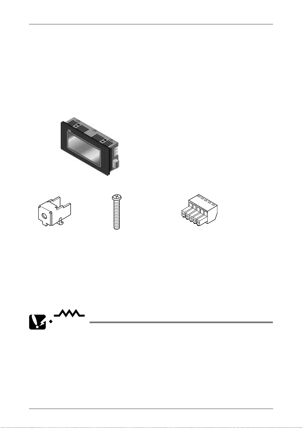
Items Included with the GT10 (AIGT1000B)
Main unit
Set of attachment fittings
Attachment fittings x 4 Attachment screws x 4
Front panel protective sheet
There is a front panel protective sheet,
available as an optional product, attached
to the front panel of the unit.
Installation instructions
Please read these instructions carefully before using the product.
CAUTION
Communication connector
Waterproof packing
One piece of waterproof packing
has been attached to unit.
• There is a film over the front panel protective sheet. Remove this film
when using the unit. For instructions on removing the film, see page
131.
• Front panel protective sheets for replacement are available as a
separate purchase (AIGT180). Please see page xix.
• Waterproof packings for replacement are available as a separate
purchase (AIGT181). Please see page xix.
xiii
Page 15
GT10/GT30
Confirming the Package Contents
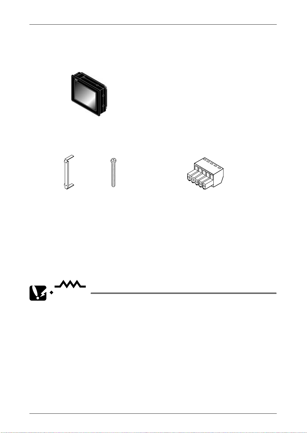
Items Included with the GT30 (AIGT3100B/AIGT3300B)
Main unit
STN monochrome liquid crystal display type: AIGT3100B
STN color liquid crystal display type: AIGT3300B
Set of attachment fittings
Fittings x 2 Screws x 4
Front panel protective sheet
There is a front panel protective sheet,
available as an optional product, attached
to the front panel of the unit.
Installation instructions
Please read these instructions carefully before using the product.
CAUTION
Communication connector
Waterproof packing
One piece of waterproof packing
has been attached to unit.
• There is a film over the front panel protective sheet. Remove this film
when using the unit. For instructions on removing the film, see page
131.
• Front panel protective sheets for replacement are available as a
separate purchase (AIGT380). Please see page xix.
• Waterproof packings for replacement are available as a separate
purchase (AIGT381). Please see page xix.
• A replacement backlight (AIGT382) is available, sold separately.
Please see page xix for details.
• The commercially available CR2032 should be used for battery
replacement.
xiv
Page 16
GT10/GT30
Confirming the Package Contents
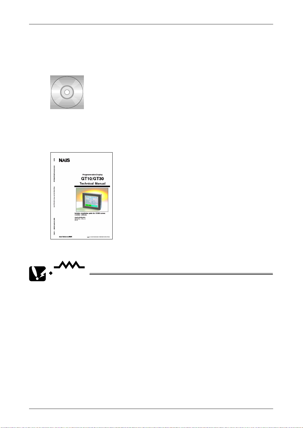
Items Included with the Terminal GTWIN English–language version
(AIGT8001V2)
Terminal GTWIN CD–ROM
Software usage license agreement and user card
Read the “Software usage license agreement” carefully, and fill in the user card. Please
return the user card to Matsushita.
GT10/GT30 Technical Manual
This is the manual you are currently reading. It contains instructions on installing and
booting GTWIN. Please read it carefully before using your product.
CAUTION
About the software usage license agreement and user card
• Before using GTWIN, read the “Software usage license agreement”
carefully.
• The license agreement comes as a set with the user card. Fill in the
user card, and return it to Matsushita. The user card is necessary in
order to obtain support services such as future version upgrades and
technical support. Don’t forget to return the card in order to be
eligible for such services.
• The serial number needed in order to install GTWIN is found on the
user card. Please make a copy of it before returning the card, and
keep it in a safe place.
xv
Page 17
GT10/GT30
Confirming the Package Contents
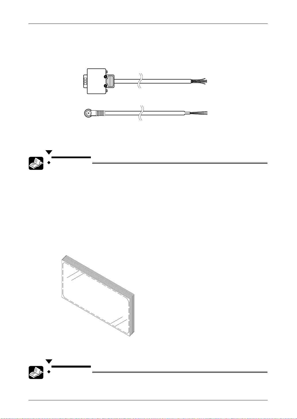
Items Included With the PLC Connection Cable (AIGT8192 / AIP81842D)
Cable
One of the following two cables has been included with the product you have purchased.
AIP81842D
(2m)
AIGT8192
(2m)
Wiring diagram
The package includes a diagram that shows the internal wiring of the cables pictured
above.
REFERENCE
For information on connecting and wiring the cables shown above and
the PLC, please refer to page 41, Chapter 4, “Connecting and
Communicating with the PLC”.
Items Included with the Front Panel Protective Sheet (AIGT180/AIGT380)
Front panel protective sheet
In order to protect the touch panel on the GT series and keep it clean, one front panel
protective sheet is included when the unit is shipped. If this front panel protective sheet
is dirty or has become worn, it should be replaced. Replacement sheets are sold
separately, in packages of ten.
Installation instructions
Please read these instructions carefully before installing the product.
REFERENCE
For information on replacing the front panel protective sheet, please
refer to page 131.
xvi
Page 18
GT10/GT30
,
GT Series System Configuration
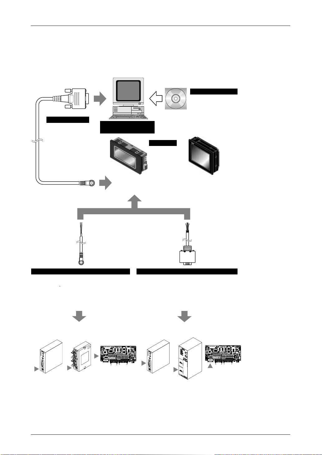
GT Series System Configuration
The following devices are necessary in order to use the GT series.
Screen creation tool
Terminal GTWIN
English–language version
Windows 95/98/2000/NT supported
Connecting cable
Screen transfer cable
D–sub 9–pin –
mini–DIN 5–pin
(3 m/9.84 ft)
Product No.: AFC8513
Commercially available
personal computer
Main unit
GTWIN CD–ROM
GT10 Technical Manual included as
accessory
Product No.: AIGT8001V2
GT10
STN monochrome liquid
crystal display
Product No.: AIGT1000B
Communication cable
PLC connecting cable (1)
For connection to TOOL port of FP0 / FP2 /
FP2SH / FP–M
Mini–DIN 5–pin loose–wire cable
(2 m/6.56 ft)
Product No.: AIGT8192
Connecting to the TOOL port of the FP0 /
FP2 / FP2SH / FP–M
GT30
STN monochrome liquid
crystal display
Product No.: AIGT3100B
Communication cable
PLC connecting cable (2)
For connection to COM. port of FP1 / FP2 / FP2SH / FP–M /
FP10SH, TOOL port of FP10SH, and computer communication unit
of FP2 / FP3
D–sub 9–pin loose–wire cable (2 m/6.56 ft)
Product No.: AIP81842D
Connecting to the COM. port of FP1 / FP2 / FP2SH / FP–M / FP10SH
TOOL port of FP10SH, and computer communication unit of FP2/FP3
GT30
STN color liquid crystal
display
Product No.: AIGT3300B
xvii
Page 19

GT10/GT30
Connecting to the COM. port of the FP0
Because connecting the unit to the COM. port of the FPΣ/FP0 requires a
loose–wire connection, this cable is not available. For more detailed
information, please see “Connecting the FPΣ” on page 42 or
“Connecting the FP0” on page 45.
GT Series System Configuration
CAUTION
xviii
Page 20
GT10/GT30
GT30 main uni
W
f
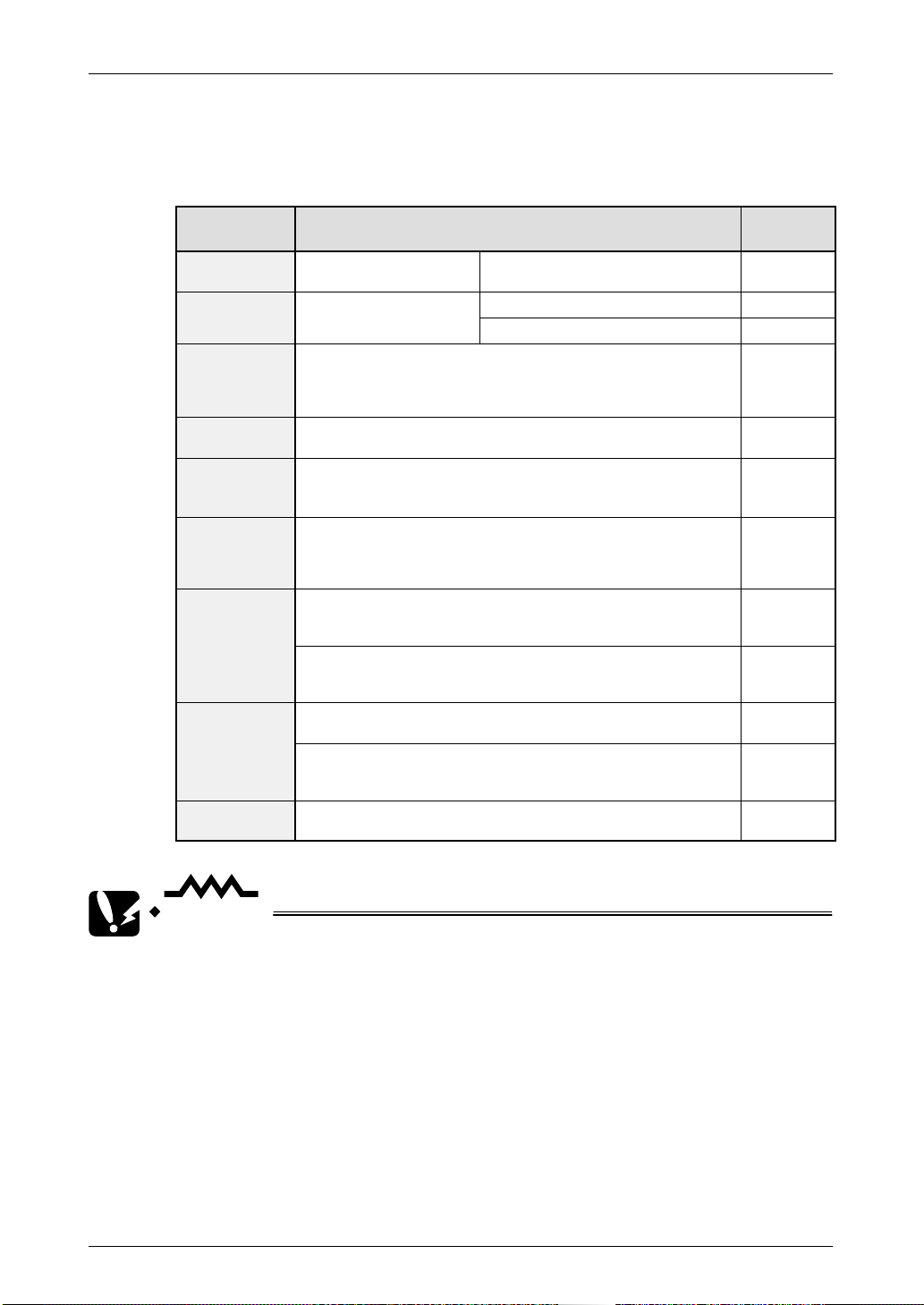
Products for the GT Series
Products types
Item Name Contents
GT10 main unit
Terminal
GTWIN
English–langua
ge version
Screen transfer
cable
PLC
connecting
cable (1)
PLC
connecting
cable (2)
Front panel
protective
sheet
aterproo
packing
Replacement
backlight
Programmable display unit
GT10 main unit
Programmable display unit
t
GT30 main unit
– “Terminal GTWIN” English–language screen creation tool
(CD–ROM)
– Set of GT10 Technical manuals (English)
Cable for transferring data between GTWIN and GT10
(3m/)
For connection to TOOL port of FP0 / FP2 / FP2SH / FP–M
Mini–DIN 5–pin loose–wire cable (2m)
For connection to COM. port of FP1 / FP2 / FP2SH / FP–M /
FP10SH, TOOL port of FP10SH, and computer communication unit
of FP2 / FP3
D–sub 9–pin loose–wire cable (2m)
Front panel protective sheet for GT10 (for replacement).
Ten i n se t .
* 1 sheet included with GT10 when shipped.
Front panel protective sheet for GT30 (for replacement).
Ten in set.
* 1 sheet included with GT30 when shipped.
Waterproof packing for GT10 (for replacement). Ten in set.
* 1 piece included with GT10 when shipped.
Waterproof packing for GT30 (for replacement).
Ten i n se t .
* 1 sheet included with GT30 when shipped.
This is the replacement backlight for the GT30 color/monochrome
liquid crystal display.
STN monochrome
liquid crystal display
STN monochrome liquid crystal display AIGT3100B
STN color liquid crystal display AIGT3300B
Products for the GT Series
Product
No.
AIGT1000B
AIGT8001V2
AFC8513
AIGT8192
AIP81842D
AIGT180
AIGT380
AIGT181
AIGT381
AIGT382
CAUTION
• Connecting to the COM. port of the FP0
Because connecting the unit to the COM. port of the FPΣ/FP0 requires
a loose–wire connection, this cable is not available. For more detailed
information, please see “Connecting the FPΣ” on page 42 or
“Connecting the FP0” on page 45.
• About the manual packed with the Terminal GTWIN English–language
version
The manual you are currently reading is included as an accessory
with the Terminal GTWIN English–language version. This manual
contains information only on procedures such as installing GTWIN.
For detailed information on operating GTWIN, please refer to the Help
function in the software.
xix
Page 21

GT10/GT30
Safety Precautions
Safety Precautions
Before installing, operating, servicing or inspecting this product, please make sure you
have read this manual and the installation instructions, and make sure the product is
used correctly.
This manual uses two safety standard levels: “WARNING” and “CAUTION”.
WARNING
Erroneous handling of an item marked with this label can cause fatal or critical injury to
the user.
• If this product is used in applications where accidents involving
bodily injury and/or significant damage may be conceivable,
measures should be taken to ensure adequate safety, such as the
use of duplicate safety mechanisms.
• The functions of the GT series should not be used to design
systems which may pose a threat to human life or which may cause
severe injury or damage. Designs should include safety
mechanisms for use in the event that switch functions malfunction.
• Do not use this product in an environment where combustible gases
are present. (This can cause explosion.)
• Do not dispose of it by incineration. (This can cause it to explode.)
CAUTION
Erroneous handling of an item marked with this label can cause injury to the user, or
physical damage to property.
• This product should not be used outside of the stated specifications
ranges for ratings, service life, configuration factors and other
elements. (This can cause abnormal generation of heat and
smoke.)
• The operational force of the touch panel should be kept to 0.98 N or
lower. Operating the touch panel at a higher force could cause
damage.
• Never touch terminals while the power supply is on. (This can cause
electric shock.)
• Never disassemble or alter this product. (This can cause electric
shock and smoke generation.)
xx
Page 22

GT10/GT30
Safety Precautions
Special Items
Maximum attention has been given to quality control of this product; however:
(1) In order to prevent, as much as possible, unexpected situations not covered by these
specifications, please consult us regarding your product’s specifications and demands,
as well as this unit’s operating conditions and installation details.
(2) To avoid the unlikely event of a situation attributed to inferior quality of the unit which
has serious adverse affects on persons or property, the numeric values for guaranteed
characteristics and performance noted in this specifications manual should be
considered the minimum necessary values. As the manufacturer of this unit, we
recommend incorporating additional safety measures such as duplicate circuits
wherever possible.
(3) The quality of this product is guaranteed for one year after purchase, and this
guarantee is limited to the range of items stated in these specifications. In the case of
a defect in the product which is clearly Matsushita’s responsibility, we will offer a
replacement unit or replacement of the defective part(s) of the unit and we will repair the
unit promptly at the place of purchase. The following are not included in the warranty:
1. Other damage resulting from damage to or defects in the supplied product.
2. Problems caused by conditions other than those noted in these specifications
involving use, storage, or shipment (transport) after product delivery.
3. Developments which were unforeseeable given the technology in practical use prior
to product delivery.
4. Earthquake, flood, fire, war, and damage due to other naturally occurring events or
human disasters for which Matsushita bears no responsibility.
xxi
Page 23

GT10/GT30
Safety Precautions
xxii
Page 24

Chapter 1
Specifications
Page 25
GT10/GT30 1.1 GT10/GT30 Specifications
ItemGT10
ificati
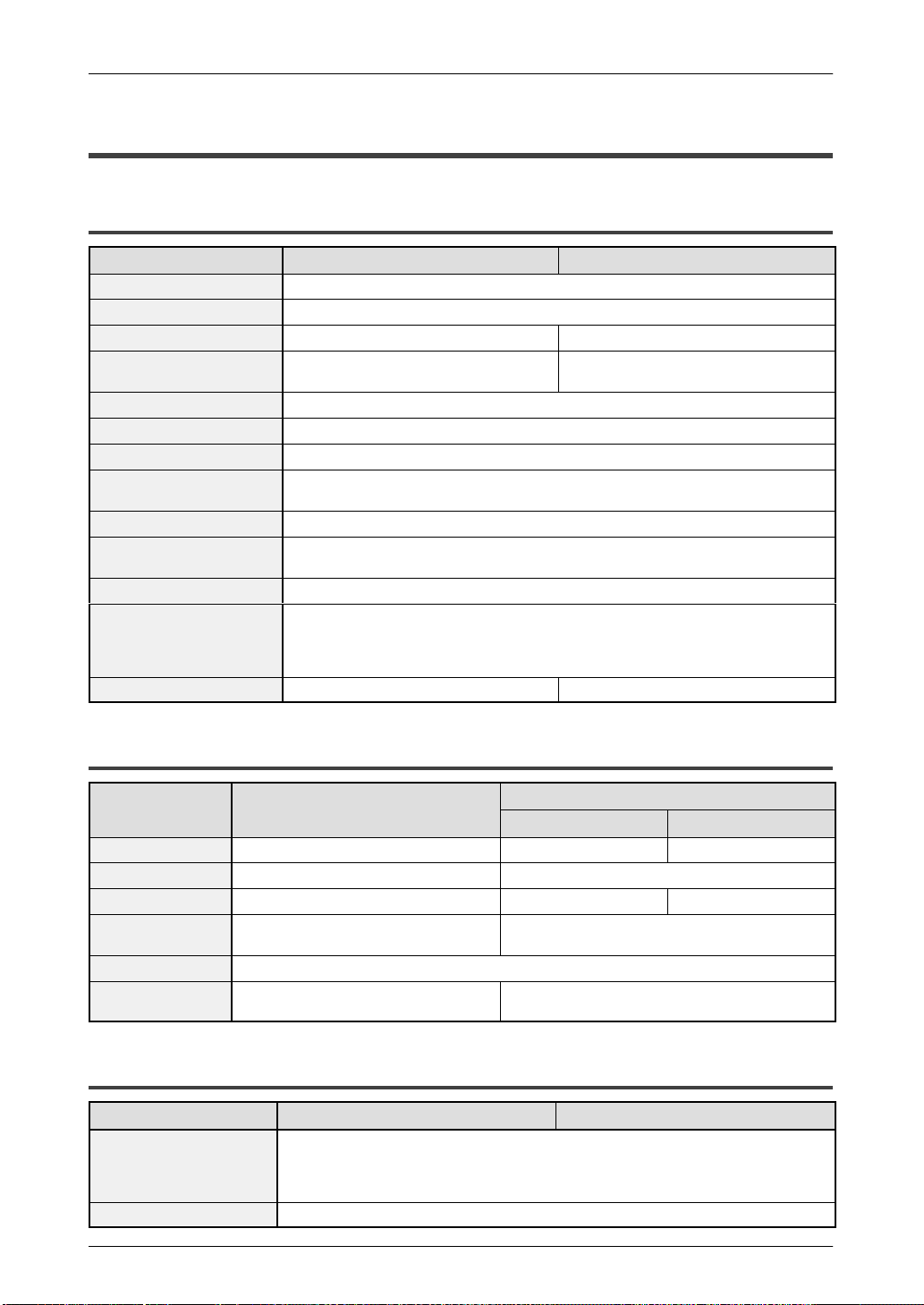
1.1 GT10/GT30 Specifications
1.1.1 General Specifications
Item GT10 specifications GT30 specifications
Rated voltage 24 V DC
Operating voltage range 21.6 to 26.4 V DC
Power consumption 5 W max. 10 W max.
Ambient temperature
Ambient humidity 20% RH to 85% RH (non condensing)
Storage temperature –20°C to 60°C/–4°F to 140°F
Storage humidity 10% RH to 85% RH (non condensing)
Vibration resistance
Shock resistance 98 m/s2 min., 4 times on 3 axes
Noise immunity
Static noise resistance 5,000 V min. (panel display)
Protective construction
Mass Approx. 260 g/9.171 oz Approx. 440 g/15.519 oz
0°C to 40°C/32°F to 104°F
(25 V DC max. if installed horizontally)
10Hz to 55 Hz (1–minute cycle)
Amplitude: 0.75 mm, 10 min on 3 axes
1,000 V [p–p] min., pulse width 50 ns, 1 µs between power supply terminals (based
on noise simulator)
IP65 (in initial status)
Dustproof and drip–proof from front panel only (packing used on panel contact surface)
* When reattaching, replace waterproof packing.
0°C to 50°C/ 32°F to 122°F
(25 V DC max. if installed horizontally)
1.1.2 Display
spec
Display STN monochrome LCD STN monochrome LCD STN color LCD
Resolution 160 (W) x 64 (H) dots 320 (W) x 240 (H) dots
Display color 2 colors (black/white) 2 colors (blue/white) 16 colors
Displayable area
LCD life Average: 50,000 hours (at normal temperature of 25°C)
Backlight
92.8 (W) x 37.1 (H) mm
3.65(W) inch x 1.46 (H) inch
3–color LED backlight (green, red,
orange) * No replacement necessary
ons
GT30 specifications
AIGT3100B AIGT3300B
118.18 (W) x 89.38 (H) mm
4.65 (W) inch x 3.52 (H) inch
CFL * Average backlight service life: 50,000 hours
(25°C)
1.1.3 Functions
Item GT10 specifications GT30 specifications
Fixed fonts: 1/4 width (8 x 8), half width (16 x 8), full width (16 x 16)
Displayable fonts
Character types Alphanumeric characters
Half width and full width characters can be displayed at same width, doubled width, or
quadrupled width
True Type fonts
2
Page 26
GT10/GT30 1.1 GT10/GT30 Specifications
GT30 specificationsGT10 specificationsItem
Graphics
Number of screens
Part functions Messages, lamps, switches, data, bar graphs, clocks, keyboard
Clock functions Clock built into main unit (can also be displayed with reference to PLC clock)
Contrast adjustment Contrast can be adjusted using touch panel operation
Automatic
communication settings
Debugging functions
Screen creation
Straight lines, continuous straight lines, squares, circles, ovals, arcs, elliptic arcs, fan
shapes, elliptic fan shapes, beveled squares, bitmaps
Approx. 160 screens
Screen numbers that can be set: Base
screens No. 00 to FF (HEX)
Number of screens that can be registered varies depending on registered contents.
Settings for communication between dedicated software and PLC set automatically by
connecting cable
Through function (PLC can be debugged from personal computer by connecting computer to TOOL port and PLC to COM. port)
Approx. 220 screens (monochrome LCD
type)
Approx. 160 screens (color LCD type)
Screen numbers that can be set: Base
screens No. 00 to 3FF
Dedicated software Terminal GTWIN used.
Applicable OS: Windows 95/98/2000/NT (Ver. 4.0 or later )
1.1.4 Touch Key
Item GT10 specifications GT30 specifications
Touch key resolution
Touch key operation
Touch key life
20 (W) x 8 (H)
0.98 N max.
6
Min. 10
16 (W) x 12 (H)
1.1.5 Memory (1)
Screen data and GTWIN Configuration Settings data
GT30 specifications
Item GT10 specifications
Memory type F–ROM F–ROM F–ROM
Memory capacity
384 kbytes
AIGT3100B
(monochrome LCD type)
1.5 Mbytes 3.25 Mbytes
AIGT 3300B
(color LCD type)
1.1.6 Memory (2)
Clock data and PLC device storage data (24 words max.)
Item GT10 specifications GT30 specifications
Memory SRAM
Memory backup
Backed up by internal secondary battery
(charged when power is on)
(Note) When using, set operation mode
switch on back of main unit to “ON” position.
Lithium battery (replaceable type)
CR2032 (commercially available)
3
Page 27
GT10/GT30 1.1 GT10/GT30 Specifications
Conditions for
1.1.7 Interface
Item GT10 specifications GT30 specifications
Communications ratings Conforms to RS232C
COM.
Port
TOOL
port
Baud rate: 9600, 19200, 38400,
Conditions for
communications with
external devices
Protocol FP series supported/general–purpose RS232C supported
Connector Connector terminal base (5–pin)
Communications ratings Conforms to RS232C
Conditions for
communications with
external devices
Protocol Dedicated protocol
Connector
57600, 76800, 115200 bits/s
Data bits: 7 or 8 bits
Parity: None, Odd, Even
Stop bits: 1 bit
Baud rate: 9600, 19200, 115200 bits/s
Data bits: 8 bits
Parity: None, Odd, Even
Stop bits: 1 bit
Mini–DIN (5–pin)
Baud rate: 9600, 19200, 38400,
57600, 115200 bits/s
4
Page 28
GT10/GT30 1.2 GT10 Names and Functions of Parts
1.2 GT10 Names and Functions of Parts
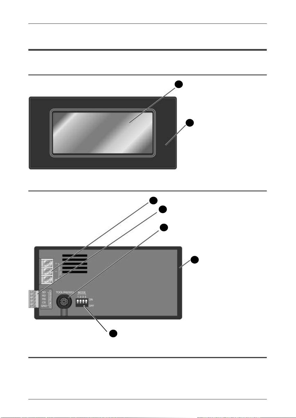
1.2.1 GT10 (front)
Liquid crystal display panel
1
(touch panel)
2
Front panel protective sheet
(one sheet is attached to unit
when unit is shipped)
1.2.2 GT10 (rear)
3
Power supply terminal
4
5
Operation mode setting switches
6
COM. port (PLC/external device connection
port) (1 communication connector provided as
accessory when when unit is shipped)
TOOL port (connection port for GTWIN
screen creation tool)
7
Waterproof packing
(1 piece is attached to unit when
unit is shipped)
1.2.3 Names and Functions of Parts
(1) Liquid crystal display panel / touch panel
Various screens are displayed here. A touch panel is provided on the liquid crystal
display panel, and switches can be operated and data entered simply by touching the
panel.
5
Page 29
GT10/GT30 1.2 GT10 Names and Functions of Parts
(2) Front panel protective sheet
This protects the touch panel and keeps it clean. One sheet is attached to the panel when
the unit is shipped.
(3) Power supply terminal
The operation power supply is connected here.
(4) COM. port (PLC/external device connection port)
A device such as a PLC, a higher–order computer, or a microcomputer board can be
connected to this RS232C port. (One communication connector is provided as an
accessory when the unit is shipped.)
(5) TOOL port (GTWIN connection port)
This port is used to connect a personal computer in which the screen creation tool
GTWIN has been installed, using a dedicated cable (AFC8513).
(6) Operation mode setting switches
With the GT10, screen data and configuration settings data are stored in an internal
F–ROM, so no battery backup is needed. However, data such as clock data and the Hold
PLC Device Data is stored in the internal SRAM, and is backed up by the internal
secondary battery, which is charged when the power supply is turned on.
The operation mode setting switches control the ON/OFF settings for the secondary
battery backup function, the ability to shift to the system menu, and other functions.
Operation mode setting
switches
MODE
12
(settings when shipped)
43
Switch no. Function OFF ON
1
ON
2 Inhibits system menu shift Shift possible Shift inhibited
3 Usage inhibited Should always be in the OFF position
OFF
4
SRAM backup using
secondary battery
No Ye s
when unit is used
(7) Waterproof packing
This assures that the front panel is waterproof. One piece is provided as an accessory
when the unit is shipped.
CAUTION
SRAM backup by the secondary battery
When the unit is shipped, the No. 1 operation mode setting switch is
set to the “OFF” psosition, in order to prevent excessive discharging
of the secondary battery. Before using the unit, turn on the No. 1
operation mode setting switch on the back of the main unit, to turn on
the SRAM backup function of the secondary battery. For detailed
information on the secondary battery, please see page 128, “What the
Internal Secondary Battery Does”.
6
Page 30

GT10/GT30 1.3 GT30 Names and Functions of Parts
1.3 GT30 Names and Functions of Parts
1.3.1 GT30 (front)
Liquid crystal display panel
1
(touch panel)
Front panel protective sheet
2
(one sheet is attached to unit
when unit is shipped)
1.3.2 GT30 (rear)
Waterprrof packing (1 piece is attached to unit
7
when unit is shipped)
Tool port (connection port for GTWIN screen
5
creation tool)
6
Operation mode setting switches
COM. port (PLC/external device connection port)
4
(1 communication connector provided as
accessory when unit is shipped)
Power supply terminal
3
1.3.3 Names and Functions of Parts
(1) Liquid crystal display panel / touch panel
Various screens are displayed here. A touch panel is provided on the liquid crystal
display panel, and switches can be operated and data entered simply by touching the
panel.
(2) Front panel protective sheet
This protects the touch panel and keeps it clean. One sheet is attached to the panel when
the unit is shipped.
7
Page 31

GT10/GT30 1.3 GT30 Names and Functions of Parts
(3) Power supply terminal
The operation power supply is connected here.
(4) COM. port (PLC/external device connection port)
A device such as a PLC, a higher–order computer, or a microcomputer board can be
connected to this RS232C port. (One communication connector is provided as an
accessory when the unit is shipped.)
(5) TOOL port (GTWIN connection port)
This port is used to connect a personal computer in which the screen creation tool
GTWIN has been installed, using a dedicated cable (AFC8513).
(6) Operation mode setting switches
The operation mode setting switches control the ability to shift to the system menu, and
other functions.
Operation mode setting
switches
MODE
12
(settings when shipped)
43
Switch no. Function OFF ON
1
ON
2 Inhibits system menu shift Shift possible Shift inhibited
3 Usage inhibited Should always be in the OFF position
OFF
4
Usage inhibited Should always be in the OFF position
when unit is used
when unit is used
(7) Waterproof packing
This assures that the front panel is waterproof. One piece is provided as an accessory
when the unit is shipped.
CAUTION
With the GT30, screen data and configuration settings are stored in the
internal F–ROM. Clock data and PLC device hold data are stored in the
internal SRAM, however, and can be backed up by the lithium battery (a
replaceable battery). When replacing the lithium battery, be sure to
insert the new battery within 20 seconds of removing the old one, to
avoid losing the data.
8
Page 32

GT10/GT30 1.4 Internal Wiring Connections for Ports
1.4 Internal Wiring Connections for Ports
1.4.1 COM. Port
When connecting the unit to the FP series, there is
no need to wire both the RS and CS.
Wiring and cables should be laid out in such a way
that cables are not affected by external noise. Also,
shielded wiring should be used for cables.
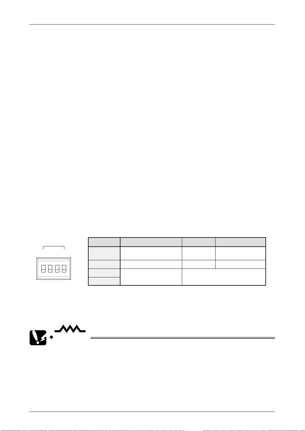
1.4.2 TOOL Port
2
4
5
1
3
Pin No. Contents
1 SG
2 SD
3 RD
4 N.C.
5 (+5 V)
The +5 V of Pin 5 is reserved for the FP
Programmer II. It should not be used for
any other application.
9
Page 33

GT10/GT30 1.4 Internal Wiring Connections for Ports
JST Mfg
e
1.4.3 Power Supply Terminals
Applicable crimp terminals
– The terminal screws are M3 screws. We recommend using crimp terminals for
wiring to terminals.
+24 V
0 V
Open–tip terminals
6.0 mm
max.
Round terminals
6.0 mm
max.
F.E.
(D–type
ground)
Maker Shape
Round 1.25–MS3 0.25 mm2 to 1.65 mm20.5 N m
JST Mfg.
Co., Ltd.
Front–opening 1.25–B3A
.
Round 2–MS3 1.04 mm
Front–opening 2–N3A
Model Applicable wiring Tightening
torque
2 to
2.63 mm
The tightening torque for terminal base screws should be
between 0.5 and 0.6 N
force could cause damage.
If crimp terminals are not being used, wire with a diameter
of 0.5 mm
In keeping with the European EMC Directive (EMC Directive 89/336/EEC), the GT10 conforms to European Standards (EN50081–2:1993, EN50082–2:1995). As a condition of compatible, a ferrite core should be installed when
wiring to the terminal base (Seiwa Electric Mfg. Co., Ltd.
E04RC281613 or equivalent).
When installing make sure that the connection and power
cables are not stressed, as this could result in broken connections.
2
to 1.25 mm2 should be used for power cables.
Ferrite core
.
m, or less. Operating at a higher
2
The GT30 conform to European EMC directives (EMC Directive 89/336/EEC) and meet European EMC standards
(EN50081–2, EN6100–6–2). A ferrite core (E04SR211132
by Seiwa Electric Mfg. Co., Ltd. or an equivalent product)
should be installed when wiring connections to the terminal
base, as shown below, in order to meet these requirements.
When installing make sure that the connection and power
cables are not stressed, as this could result in broken connections.
Ferrite cor
Ferrite core
10
Page 34

GT10/GT30 1.5 Dimensions
1.5 Dimensions
1.5.1 GT10 Dimensions
8.5/0.33
(7/0.28)
144/5.67
97/3.82
138.0/5.43
80/3.15
(Display unit)
4/0.16
72/2.83
40/1.57
(Display unit)
65.8/2.59
32/1.26
2/0.08
(Packing)
(7/0.28)
9.6/0.38
60/2.36
(Unit: mm/inch)
11
Page 35

GT10/GT30 1.5 Dimensions
1.5.2 GT10 Panel Cutout Dimensions
The panel cutout dimensions of the GT10 are as shown below.
1
+
0
139
Applicable panel thickness: 1.0 to 6.0/0.002 to 0.236
1.5.3 GT30 Dimensions
177/6.97
126.8/4.99
0.04
+
0
/5.47
(Display unit)
+
+
0.04
1
0
/2.64
0
67
(Unit: mm/inch)
118.8/4.68
88/3.46 (Display unit)
158.2/6.23
150.2/5.91
4.4/0.17
(8/0.31)
Attachment fitting
(Unit: mm/inch)
38.0/1.50
3.1/0.12
12
Page 36

GT10/GT30 1.5 Dimensions
1.5.4 GT30 Panel Cutout Dimensions
The panel cutout dimensions of the GT30 are as shown below.
1
+
0
150.5
Applicable panel thickness: 1.0 to 5.0/0.039 to 0.197
/5.93
0.04
+
0
0.04
+
0
/4.69
1
+
0
119
(Unit: mm/inch)
13
Page 37

GT10/GT30 1.5 Dimensions
14
Page 38

Chapter 2
Installation and Wiring
Page 39

GT10/GT30 2.1 Installation
2.1 Installation
2.1.1 Installation Environment
When installing and using the GT series, always make sure the following conditions are
observed.
Usage Conditions
When installing the product, make sure it is used within the range of the general
specifications. Do not use in the following environments:
– Areas where the unit may come in contact with water (the unit is warranted by
IP65 for the installed panel, but this applies to initial values and operation cannot
be guaranteed in areas where the unit is constantly subjected to water or to
extreme temperatures or humidity).
– Areas where the ambient temperature exceeds the range 0°C to 40°C/32°F to
104°F (0°C to 50°C/32°F to 122°F for the GT30).
– Areas where the ambient humidity exceeds 20% RH to 85% RH.
– If the control panel and other parts are installed in an environment where the air
tends to be poorly ventilated, forced cooling should be used to keep the ambient
temperature of the from going over 40°C/104°F (50°C/122°F for the GT30). This
prevents the temperature of the GT display unit from rising.
– Locations where condensation may form because of sudden fluctuations in
temperature.
– Locations where flammable or corrosive gases are present.
– Locations where there are high concentrations of dust or iron filings.
– Locations where substances such as organic solvents (thinner, benzene, etc.) or
strong alkali substances (ammonia, caustic soda, etc.) might adhere to the
product.
– Locations where the product is subject to extreme vibration and/or impact.
– Avoid installing the product near high–voltage lines, high–voltage devices, power
lines, power devices, amateur radio sets and other transmitters, and devices that
generate strong current surges.
– Avoid locations where the display unit is subject to direct sunlight.
Safety Precautions
– The switch functions of the programmable display unit should not be used to
design systems which may pose a threat to human life or which may cause
severe injury or damage. Designs should include safety mechanisms for use in
the event that switch functions do not function correctly.
Power Supply Wiring
– For the power supply, use twisted wire (strand wire).
– There is sufficient noise resistance to offset power line noise, but we recommend
reducing noise by measures such as installing an insulated transformer.
16
Page 40

GT10/GT30 2.1 Installation
– Separate wiring systems should be used for the power supply unit and the
operating unit.
Static Electricity/Noise
– Keep the GT10/GT30 main unit, PLC connecting cable, and other wiring as far
away as possible from machines which are likely to produce noise (welding
equipment, power lines, inverters, motors, etc.).
– For use in environments where the frequent occurrence of static electricity,
radiation, or induced noise can be expected, the use of shielded cable on all
wiring and grounding of shield (1–point ground) is recommended. When wiring
the equipment, shielded wires should be electrically insulated to signal lines and
signal grounds.
– If excessive static electricity is applied to the panel surface, the LCD display unit
may be damaged.
Battery Service Life
– The service life of the internal battery will be radically shortened if used
continually in ambient operating temperatures of more than 40°C/104°F
(50°C/122°F for the GT30) or when the operating voltage exceeds 25V DC. Use
caution when using the clock and device hold area functions.
Other Precautions
– Do not leave the GT10 connected to the TOOL port of the FP Programmer II.
– Always operate the touch panel with your fingers. Excessive load (about 98
2
N/cm
) or impact (operating with tools, etc.) will cause damage. Touch panel
operation must be within the standard operating power range. Uniform pressure
should be used to avoid abnormal wear of electrodes which may disable
operation. Operate the unit only by touch.
– Never dismantle, re–assemble, or alter the unit. Performance cannot be
warranted if this precaution is disregarded.
2.1.2 GT10 Installation Method
Secure the GT10 to the installation panel using the four fittings and four screws
provided with the unit.
(1) Place the GT10 main unit in the installation panel.
17
Page 41

GT10/GT30 2.1 Installation
(2) Insert the fittings into the grooves provided in the GT10 main unit, and tighten
the screws to secure the GT10 main unit to the installation panel.
Four fittings and four screws provided
with the unit
Enlarged view
CAUTION
Screw tightening torque
The screw tightening torque should be 0.1 N m to 0.25 N m.
Applicable panel thickness
A panel with a thickness of 1.0 mm to 6.0 mm should be used.
Installation angle
If the installation angle is between 60 degrees and 0 degrees
(horizontal), the operating voltage should be set to 25V DC or lower.
Installation angle
Clearance when the GT10 is installed
When installing the GT10, if other parts are being installed to the
panel or cables are being wired to it, we recommend providing a
clearance of 30 mm to 50 mm/1.18 inch to 1.97 inch around the
GT10. This prevents cables from being damaged, and facilitates the
installation work. Also, make sure that the slits in the main unit are
never obstructed.
18
Page 42

GT10/GT30 2.1 Installation
2.1.3 GT30 Installation Method
Secure the GT30 to the installation panel using the two fittings and four screws provided
with the unit.
(1) Place the GT30 main unit in the installation panel.
(2) Insert the fittings into the grooves provided in the GT30 main unit, and tighten
the screws to secure the GT30 main unit to the installation panel.
Slits (located all the way around the periphery)
Attachment screws
Installation panel
CAUTION
Attachment fittings
Screw tightening torque
The screw tightening torque should be 0.1 N m to 0.25 N m.
Tightening the screws too hard can cause deformation of the front
panel , so that the switch will not function properly. Make sure
screws are tightened to the appropriate degree.
Applicable panel thickness
A panel with a thickness of 1.0 mm to 5.0 mm should be used.
Installation angle and ambient temperature range for usage
If the unit is being installed in a horizontal orientation and the
Matsushita Programmer II and C–NET adaptor are being connected
to the Tool port, please be aware that the ambient usage
temperature should not exceed 40°C/104°F.
Liquid display panel side
Installation panel
(Horizontal installation)
Clearance when the GT30 s installed
When installing the GT30, if other parts are being installed to the
panel or cables are being wired to it, we recommend providing a
19
Page 43

GT10/GT30 2.1 Installation
clearance of 30 mm to 50 mm/1.18 inch to 1.97 inch around the
GT30. This prevents cables from being damaged, and facilitates the
installation work. Also, make sure that the slits in the main unit are
never obstructed.
20
Page 44

GT10/GT30 2.2 Wiring the Power Supply
2.2 Wiring the Power Supply
The power supply should be wired by securely connecting the terminal on the rear of
the main unit to the terminal. Always use crimp terminals for wiring.
+24 V
+24 V
0 V
(D–type ground)
F. E.
+24 V
0 V
F. E.
(D–type
ground)
Use twisted wiring for the power supply
In order to minimize influence from noise, the wiring for the power supply should be
twisted.
Insulate the power supply inside a protective circuit
– In order to protect the unit against abnormal voltage from the power supply line, the
power supply should be an insulated type, and should be enclosed within a protective
circuit.
– A non–insulated regulator is used with the GT series.
– If a power supply device without an internal protective circuit is being used, power
should always be supplied to the GT series through a fuse or a similar protective device.
Keep the power supply voltage within the operating voltage range
Operating voltage range 21.6 to 26.4V DC
Use M3 crimp terminals
– The terminal screws are M3 screws. We recommend using crimp terminals for wiring
to terminals.
Open–tip terminals Round terminals
6.0 mm
max.
Maker Shape Model
Round 1.25–MS3 0.25 mm2 to 0.5 N·m
JST Mfg.
JST Mfg.
Co., Ltd.
Front–opening 1.25–B3A
Round 2–MS3 1.04 mm2 to
Front–opening 2–N3A
6.0 mm
max.
Applicable
wiring
1.65 mm
2.63 mm
Tightening
torque
2
2
The tightening torque for terminal
base screws should be between 0.5
and 0.6 N·m, or less. Operating at a
higher force could cause damage.
If crimp terminals are not being
used, wire with a diameter of 0.5
mm2 to 1.25 mm2 should be used
for power cables.
For precautions concerning conformance to European EMC directives, please see “Power
Supply Terminals” on page 10.
21
Page 45

GT10/GT30 2.2 Wiring the Power Supply
Keep the power supply wiring separate
– Wiring to the GT series, PLC, and other power equipment should have separate wiring
systems.
Breaker
Power
equipment
PLC
GT series
Insulated DC
power supply
22
Page 46

GT10/GT30 2.3 Wiring the COM. Port
2.3 Wiring the COM. Port
Accessory communication connector/applicable wiring
The communication connector used for the COM. port (provided as an accessory with
the main unit) has a screw–tightening type of terminal base. The wiring shown below
should be used.
Accessory communication connector
The communication connector is made by Fenics Contact Co., Ltd.
No. of pins
5–pin MC1, 5/5 –ST–3,5 1840396
Fenics Model No.
Model No. Product No.
Applicable wiring (twisted wiring)
Size Conductor Cross–Section Surface Area
AGW#28 to 1 6 0.08 mm2 to 1.25 mm
2
Applicable stick–type terminals with insulated sleeves
If stick–type terminals are used, the models listed below are marketed by Fenics
Contact Co., Ltd.
Maker Cross–Section Surface Size Fenics Co. Model
2
2
2
2
AGW#24 AI 0,25 to 6 YE
AGW#20 AI 0,50 to 6 WH
AGW#18 AI 0,75 to 6 GY
AGW#18 AI 1 to 6 RD
Fenics Contact
Fenics Contact
Co., Ltd.
0.25 mm
0.50 mm
0.75 mm
1.00 mm
Crimp tools for stick–type terminals
Maker
Fenics Contact Co., Ltd. CRIMPFOX UD6 1204436
Fenics Model No.
Model No. Product No.
Use a special tool to tighten the terminal base of the communication connector
Tightening of terminals should be done using a screwdriver made by Fenics Contact
Co., Ltd. (Fenics mfg. no. 1205037, blade width 0.4 x 2.5, model no. SZS 0.4 x 2.5), or
a screwdriver made by Matsushita Electric Works Co., Ltd. (Product number AFP0806).
The tightening torque should be 0.22 N·m to 0.25 N·m or less.
23
Page 47

GT10/GT30 2.3 Wiring the COM. Port
2.3.1 Wiring Method
(1) Remove the sheath from the wire.
7 mm/0.28 inch
(2) Insert the wire all the way into the terminal base, and tighten the screw in the
clockwise direction to secure it.
2.3.2 Precautions Concerning Wiring
The following precautions should be observed, to avoid broken or disconnected wires.
– When removing the sheath, be careful not to scratch the core wire.
– Wire the terminal without twisting the core wire.
– The core wire should be connected without soldering it. Vibration can sometimes
cause soldered connections to break loose.
– After connecting the wiring, avoid subjecting the cable to stress.
– Because of the construction of the terminal, tightening the wire in the
counterclockwise direction will cause a faulty connection. If this happens,
disconnect the wire, check the terminal hole, and connect the wire again.
CounterclockwiseClockwise
REFERENCE
For information on connecting the COM. port of the GT series with
various PLC units, please see Chapter 4, “Connecting and
Communicating with the PLC”, on page 41.
24
Page 48

Chapter 3
Setup
Page 49

GT10/GT30 3.1 Setup Procedure for the GT10
3.1 Setup Procedure for the GT10
The GT10 should be set up using the procedure outlined below.
(1) Setting the “Configuration File” with GTWIN
The GT10 has an internal file called the “Configuration file”, which is used to determine
various operating environment parameters. When the GT10 is shipped from the factory,
the settings listed below are set for the parameters in the configuration settings file. If
changes are made to these settings, they are made from GTWIN screen creation tool.
(For detailed information on changing settings, see page 73 and subsequent pages.)
If the GT10 is being used without changing the factory settings, the following setup
procedure is not necessary.
Contents of configuration settings for GT10 when shipped from the factory
Classification Item Setting contents
Basic Setup
Communication
parameter
parameter
settings
Auto paging Automatic paging No
Startup screen
Startup screen
settings
Other settings
Other settings
Hold PLC Device Holds a PLC device Not held
GT internal
device hold
Area for basic
communication
with PLC
COM. port
TOOL port
Startup screen No. 00
Rise delay time 0 seconds
Clock GT main unit clock / external transmission: No
Backlight control Not turned of f automatically
Touch operation
sounds
GT internal device
hold
Mode : GT10 mode
Word area: DT0 to DT2
Bit area : WR0 to WR2
Communication speed: 19200 bits/s, data length: 8 bits, stop bit: 1 bit, parity: odd
<Communication error temporary processing> Retries: 3, error code displayed
(not held)
Communication speed: 19200 bits/s, data length: 8 bits, stop bit: 1 bit, parity: odd
<Through function local setting> None
Valid
Not held
Always confirm “Basic communication area to PLC” under “Basic Setup”
This is an internal device area that comes already provided in the GT10 for the purpose
of communicating with a PLC. If the factory settings are to be changed, the setup
procedure must be carried out. For detailed information, please see page 29.
(2) Connect the GT10 and the personal computer.
After the settings have been entered with GTWIN, connect the computer and the GT10,
using the screen transfer cable.
GTWIN
Screen transfer
cable (AFC8513D)
GT10
26
Page 50

GT10/GT30 3.1 Setup Procedure for the GT10
(3) Transfer the GT10 Configuration file from GTWIN.
After connections have been completed, use the following procedure to transfer the
GT10 Configuration file from GTWIN.
Boot GTWIN, and select “Transfer” on the “File” menu.
When the transfer function is selected, a dialog box for file transfer is displayed.
At this point, specify the type of data to be transferred, and the direction of
transfer.
Transfer data: “GT10 Configuration”
Transfer direction: “GTWIN → GT main unit”
Enter the above conditions and click on the “OK” button. The system files are
transferred to the GT10.
27
Page 51

GT10/GT30 3.1 Setup Procedure for the GT10
When the menu operation as shown at the left page is carried out, the configuration file
is sent to the GT10. During the transfer, a screen like that shown below is displayed.
GTWIN
GT10 Configuration
file being transferred
Screen transfer cable
(AFC8513D)
Transferring
PC→GT
GT10
(4) Setup is completed.
If the transfer has been completed without any problems, the setup is completed.
CAUTION
Backup of the GT10 Configuration file
The GT10 Configuration file is stored in the user memory (F–ROM) of
the GT10. This file is deleted if the memory is initialized using the
command on the system menu of the GT10 main unit (see page 89),
and will have to be transferred again.
28
Page 52

GT10/GT30 3.2 Setting the Basic Communication Area, GT10 and PLC
3.2 Setting the Basic Communication Area, GT10 and PLC
3.2.1 What is the Basic Communication Area?
Communication between the GT10 and PLC is carried out as shown below.
Basic communication area
For screen switching settings and system
control
Ongoing
Communication
GT10
As shown in the illustration, communication is carried out on an ongoing basis between
the GT10 and internal devices in the PLC. Internal PLC devices are divided into the
following two devices:
Basic communication area
This area is for system control, such as screen switching settings. PLC devices belong
to this area on a fixed basis, and communication is constantly being carried out.
Breakdown of the basic communication area
Word devices (DT, FL, etc.)
(word device / bit device: 3 words each)
Part reference / output device
For part functions
(free device specification)
Internal PLC devices
Bit devices (WR, etc.)
PLC
3 consecutive words
3 consecutive words
– Word devices ––– For reading devices handled in word units (3 consecutive words)
– Bit devices ––– For reading devices handled in bit units (3 consecutive words)
References and output devices for parts
These are devices that are used in parts functions, and can be freely specified by the
user. Communication is carried out on an ongoing basis only for those that are currently
displayed on the screen and pertain to devices currently in use.
With the GT10, before GTWIN screen creation tool is used to specify the devices for
parts functions, the “basic communication area” must be determined.
DT0 to DT2 and WR0 to WR2 are set as the default values for the basic communication
area, but the initial address can be changed using the following procedure.
CAUTION
The basic communication area should be used in the PLC ladder
program to control the GT main unit.
Settings in GTWIN
Select “Configuration” under “File” on the menu bar, and then select the sub–menu
called “GT Configuration”. This displays the dialog box for the GT10 Basic Setup, as
29
Page 53

GT10/GT30 3.2 Setting the Basic Communication Area, GT10 and PLC
shown below.
Clicking on the
button in “Basic Communication Area to PLC” displays the device
settings dialog box shown below, where the initial addresses for the word area and bit
area can be changed.
GT10 Configuration Basic Setup dialog box
EXPLANATION
Key operation in the Device Settings dialog box
Click on the
button to display a pull–down menu, and then select
the device for which settings are to be entered. Use the ten–keys to
enter the address.
The
address, and the
button acts as a backspace key when entering an
button functions as a Clear key.
3.2.2 GT10 Basic Communication Area Map
In order for communication to be carried out between the GT10 and PLC, an internal
device area like that shown below is provided in the PLC. This should be used to control
the GT main unit through the PLC ladder program actually being run.
The starting address “N” of the field shown below is specified in the GT10 configuration
settings of GTWIN screen creation tool, and is then sent to the GT main unit.
30
Page 54

GT10/GT30 3.2 Setting the Basic Communication Area, GT10 and PLC
Word devices
Word position F E D C B A 9 8 7 6 5 4 3 2 1 0
N+0 Screen no. specified by PLC (area read by GT10 from PLC)
N+1 Usage prohibited
N+2 No. of currently displayed screen (area in which data is written from GT10 to PLC)
Explanation of system area
Screen no. specified by PLC ––– The screen number displayed on the GT10 is
specified from the PLC in hexadecimal format.
No. of currently displayed screen ––– The number of the screen currently
displayed on the GT10 is written to the PLC in hexadecimal format.
Bit devices
Word
position
N+0 BZ
N+1 Usage prohibited
N+2 BAT
F E D C B A 9 8 7 6 5 4 3 2 1 0
Forced–
display flag
Explanation of system areas
Backlight
Valid flag
Backlight
Flashing
Backlight
Color
Data Input In
Progress flag
BZ ––– This turns on the buzzer.
Forced–Display flag ––– At the rise when the bit is turned on, the screen specified by
the PLC is forcibly displayed. (This is executed only when at the rise of the bit.)
Backlight Valid flag ––– When the bit is turned on, the backlight flashing/backlight
color control becomes effective.
Backlight Flashing ––– 0: Lighted (normal), 1: Flashing
Backlight Color ––– 00: Off, 01: Green, 10: Red, 11: Orange
BAT ––– This goes on if clock data and Hold PLC Device data held in the SRAM are
not being backed up normally. (This bit also goes on if the SRAM is not backed up by
the internal secondary battery.)
Data Input In Progress flag ––– This is 1 while data is being input, and 0 when data
input has been completed.
EXPLANATION
“IOP01” mode
The GT10 is equipped with an IOP01 mode for users with
conventional models (I.O.P. B01C / M01L / D01TL series).Using this
function enables compatibility with earlier models, so that
communication is possible between the GT10 and PLC, except for
one part of the basic communication area.
Entering settings for the IOP01 mode
Click on the “File” menu in GTWIN, and then select “Configuration”
from the displayed menu. Next, select “GT Configuration” from the
31
Page 55

GT10/GT30 3.2 Setting the Basic Communication Area, GT10 and PLC
sub–menu. Turn on the radio button for “IOP01 Mode” in the
displayed dialog box.
For information on the displayed dialog box, please see “Basic
Setup” under “GT10 Configuration Settings” on page 73.
Map of the basic communication area for conventional models
(conventional name: system area)
If the IOP01 mode is set, the basic communication area map for the
GT10 is as follows.
Reference data area
Address
n BZ PC Screen no.
n+1
n+2
n+3
•
•
•
•
Bit configuration
F E D C B A 9 8 7 6 5 4 3 2 1 0
Tag bit field * Note 1
(Used to turn tag display on/off, display status screen segments, and display settings)
(Used to turn tag display on/off, display status screen segments, and display settings)
Tag field * Note 1
(Used to switch tags, specify movements, and reference and set data)
(Used to switch tags, specify movements, and reference and set data)
System field
(fixed at 2
words)
Field for
user use
(fixed at
126 words
maximum)
Output destination relay
Address
n
n+1 BAT SET
n+2
n+3
•
•
Bit configuration
F E D C B A 9 8 7 6 5 4 3 2 1 0
System switch output destination
Not supported
* Note 2
Output destination relay * Note 1
Output destination relay * Note 1
(Used for switch output destinations of tags, segments, and manual switches)
NOTES
1) The tag bit field and tag field under “Reference data area”, and the
output destination relay field under “Output relay” can be switched
just as they are, as device setting destinations for GT10 parts
functions.
2) System switch output destinations and function switch output
destinations provided in conventional models as the initial
addresses under “Output relay” are not supported with the GT10.
Function switch output destination
Not supported
* Note 2
Displayed screen data (no. of screen
Displayed screen data (no. of screen
currently displayed)
System field
(fixed at 2
words)
Field for
user use
(fixed at 30
words maximum)
32
Page 56

GT10/GT30 3.2 Setting the Basic Communication Area, GT10 and PLC
System switches should be replaced with keyboard parts, and
function switches with switch parts.
33
Page 57

GT10/GT30 3.3 Setup Procedure for the GT30
Other settings
3.3 Setup Procedure for the GT30
The GT30 should be set up using the procedure outlined below.
(1) Setting the “Configuration File” with GTWIN
The GT30 has an internal file called the “Configuration file”, which is used to determine
various operating environment parameters. When the GT30 is shipped from the factory,
the settings listed below are set for the parameters in the configuration settings file. If
changes are made to these settings, they are made from GTWIN screen creation tool.
(For detailed information on changing settings, see page 109 and subsequent pages.)
If the GT30 is being used without changing the factory settings, the following setup
procedure is not necessary.
Contents of configuration settings for GT30 when shipped from the factory
Classification Item Setting contents
Basic Setup
Communication
parameter
parameter
settings
Auto paging Automatic paging No
Startup screen
Startup screen
settings
Other settings
Hold PLC Device Holds a PLC device Not held
GT internal
device hold
Area for basic
communication
with PLC
COM. port
TOOL port
Startup screen No. 00
Rise delay time 0 seconds
Clock GT main unit clock / external transmission: No
Backlight control Not turned off automatically
Touch operation
sounds
GT internal device
hold
Word area: DT0 to DT2
Bit area : WR0 to WR2
Communication speed: 19200 bits/s, data length: 8 bits, stop bit: 1 bit, parity: odd
<Communication error temporary processing> Retries: 3, error code displayed
(not held)
Communication speed: 19200 bits/s, data length: 8 bits, stop bit: 1 bit, parity: odd
<Through function local setting> None
Valid
Not held
Always confirm “Basic communication area to PLC” under “Basic Setup”
This is an internal device area that comes already provided in the GT30 for the purpose
of communicating with a PLC. If the factory settings are to be changed, the setup
procedure must be carried out. For detailed information, please see page 37.
(2) Connect the GT30 and the personal computer.
After the settings have been entered with GTWIN, connect the computer and the GT30,
using the screen transfer cable.
GTWIN
Screen transfer
cable (AFC8513D)
GT30
34
Page 58

GT10/GT30 3.3 Setup Procedure for the GT30
(3) Transfer the GT30 Configuration file from GTWIN.
After connections have been completed, use the following procedure to transfer the
GT30 Configuration file from GTWIN.
Boot GTWIN, and select “Transfer” on the “File” menu.
When the transfer function is selected, a dialog box for file transfer is displayed.
At this point, specify the type of data to be transferred, and the direction of
transfer.
Transfer data: “GT30 Configuration”
Transfer direction: “GTWIN → GT main unit”
Enter the above conditions and click on the “OK” button. The system files are
transferred to the GT30.
35
Page 59

GT10/GT30 3.3 Setup Procedure for the GT30
When the menu operation as shown at the left page is carried out, the configuration file
is sent to the GT30. During the transfer, a screen like that shown below is displayed.
GT30 Configuration
file being transferred
GT30
GTWIN
Screen transfer cable
(AFC8513D)
(4) Setup is completed.
If the transfer has been completed without any problems, the setup is completed.
CAUTION
Backup of the GT30 Configuration file
The GT30 Configuration file is stored in the user memory (F–ROM) of
the GT30. This file is deleted if the memory is initialized using the
command on the system menu of the GT30 main unit (see page 130),
and will have to be transferred again.
36
Page 60

GT10/GT30 3.4 Setting the Basic Communication Area, GT30 and PLC
3.4 Setting the Basic Communication Area, GT30 and PLC
3.4.1 What is the Basic Communication Area?
Communication between the GT30 and PLC is carried out as shown below.
Basic communication area
For screen switching settings and system
control
Ongoing
Communication
GT30
As shown in the illustration, communication is carried out on an ongoing basis between
the GT30 and internal devices in the PLC. Internal PLC devices are divided into the
following two devices:
Basic communication area
This area is for system control, such as screen switching settings. PLC devices belong
to this area on a fixed basis, and communication is constantly being carried out.
Breakdown of the basic communication area
Word devices (DT, FL, etc.)
(word device / bit device: 3 words each)
Part reference / output device
For part functions
(free device specification)
Internal PLC devices
Bit devices (WR, etc.)
PLC
3 consecutive words
3 consecutive words
– Word devices ––– For reading devices handled in word units (3 consecutive words)
– Bit devices ––– For reading devices handled in bit units (3 consecutive words)
References and output devices for parts
These are devices that are used in parts functions, and can be freely specified by the
user. Communication is carried out on an ongoing basis only for those that are currently
displayed on the screen and pertain to devices currently in use.
With the GT30, before GTWIN screen creation tool is used to specify the devices for
parts functions, the “basic communication area” must be determined.
DT0 to DT2 and WR0 to WR2 are set as the default values for the basic communication
area, but the initial address can be changed using the following procedure.
CAUTION
The basic communication area should be used in the PLC ladder
program to control the GT main unit.
Settings in GTWIN
Select “Configuration” under “File” on the menu bar, and then select the sub–menu
called “GT Configuration”. This displays the dialog box for the GT30 Basic Setup, as
37
Page 61

GT10/GT30 3.4 Setting the Basic Communication Area, GT30 and PLC
shown below.
Clicking on the
button in “Basic Communication Area to PLC” displays the device
settings dialog box shown below, where the initial addresses for the word area and bit
area can be changed.
GT30 Configuration Basic Setup dialog box
EXPLANATION
Key operation in the Device Settings dialog box
Click on the
button to display a pull–down menu, and then select
the device for which settings are to be entered. Use the ten–keys to
enter the address.
The
address, and the
button acts as a backspace key when entering an
button functions as a Clear key.
3.4.2 GT30 Basic Communication Area Map
In order for communication to be carried out between the GT30 and PLC, an internal
device area like that shown below is provided in the PLC. This should be used to control
the GT main unit through the PLC ladder program actually being run.
The starting address “N” of the field shown below is specified in the GT30 configuration
settings of GTWIN screen creation tool, and is then sent to the GT main unit.
38
Page 62

GT10/GT30 3.4 Setting the Basic Communication Area, GT30 and PLC
Word devices
Word position F E D C B A 9 8 7 6 5 4 3 2 1 0
N+0 Screen no. specified by PLC (area read by GT30 from PLC)
N+1 Usage prohibited
N+2 No. of currently displayed screen (area in which data is written from GT30 to PLC)
Explanation of system area
Screen no. specified by PLC ––– The screen number displayed on the GT30 is
specified from the PLC in hexadecimal format.
No. of currently displayed screen ––– The number of the screen currently
displayed on the GT30 is written to the PLC in hexadecimal format.
Bit devices
Word
position
N+0 BZ
N+1 Usage prohibited
N+2
F E D C B A 9 8 7 6 5 4 3 2 1 0
Forced–
display flag
Explanation of system areas
Backlight
Valid flag
Backlight
Flashing
Backlight
Color
BAT
LOW
flag
BAT
Data Input In
Progress flag
BZ ––– This turns on the buzzer.
Forced–Display flag ––– At the rise when the bit is turned on, the screen specified by
the PLC is forcibly displayed. (This is executed only when at the rise of the bit.)
Backlight Valid flag ––– When the bit is turned on, the backlight flashing/backlight
color control becomes effective.
Backlight Flashing ––– 0: Lighted (normal), 1: Flashing
Backlight Color ––– 00: Off, 01: Lighted, 10: Lighted, 11: Lighted
BAT ––– This goes on if clock data and Hold PLC Device data held in the SRAM are
not being backed up normally. (This bit also goes on if the SRAM is not backed up by
the battery.)
Data Input In Progress flag ––– This is 1 while data is being input, and 0 when data
input has been completed.
BAT LOW flag ––– This bit goes on if the battery capacity drops too low. The battery
should be replaced within one week after this bit goes on.
39
Page 63

GT10/GT30 3.4 Setting the Basic Communication Area, GT30 and PLC
40
Page 64

Chapter 4
Connecting and Communicating with the
PLC
Page 65

GT10/GT30 4.1 Connecting the FP–Sigma
4.1 Connecting the FP–Sigma
4.1.1 Connecting to the COM. Port
GT10
FPG–COM1
AFPG801
RS232C
SGCSRSRDSD
TOOL (RS232C)
FPΣ COM. port
MODE
1 2 3 4
ON
OFF
COM. (RS232C)
SDRDRS
CS
GND
Loose–wire connection
FPΣ communication format settings
GT30
When using COM. Port 1
System
Item Value Set System
register no.
410 COM. Port 1
Unit number
412 COM. Port 1
Communication
mode
413 Data length 8 bits 414 Data length 8 bits
Parity check Yes, Odd Parity check Yes, Odd
Stop bits 1 bit Stop bits 1 bit
Line return code CR Line return code CR
Start code No STX Start code No STX
415 COM. Port 1
Communication
speed setting
1 411 COM. Port 2
Computer link
No modem
connection
19200 bits/s 415 COM. Port 2
When using COM. Port 2
Item Value Set
register no.
Unit number
412 COM. Port 2
Communication
mode
Communication
speed setting
24V
1
Computer link
No modem
connection
19200 bits/s
Connecting to the FPΣ COM. port
FPΣ
GT10/GT30
When using the RS232C 1–channel type,
the section between the RS and CS signals
on the PLC side should be shorted.
When using the RS232C 1–channel type
PLC side
Pin no. Abbreviation
SD SD
RD RD
RS RS
CS CS
GND GND
When using the RS232C 2–channel type
PLC side
Pin no. Abbreviation
S1 SD
R1 RD
S2 RS
R2 CS
GND GND
GT main unit side
GT main unit side
Pin no. Abbreviation
SD SD
RD RD
RS RS
CS CS
GND GND
Pin no. Abbreviation
SD SD
RD RD
RS RS
CS CS
GND GND
42
Page 66

GT10/GT30 4.1 Connecting the FP–Sigma
CAUTION
Because loose wiring is used for connection to the FPΣ COM. port, no
dedicated cable is available. The cable should be provided by the
customer. When purchasing a cable, the following precautions should
be observed:
Shielded wire with a size of AGW#28 to 16 (conductor
2
cross–section surface area: 0.08 mm
to 1.25 mm2) should be used
for connections.
For wiring procedures, please refer to “Wiring the COM. Port” on
page 23.
4.1.2 Connecting to the TOOL Port
GT10
GT30
FPΣ TOOL port
AIGT8192
FPΣ communication format settings
System register no. Item Value Set
410 TOOL Port
Unit number
412 Modem connection No modem connection
413 Data length 8 bits
Parity check Yes, Odd
Stop bits 1 bit
Line return code CR (Fixed)
Start code no STX (Fixed)
415 COM. Port 1
Communication speed setting
1
19200 bits/s
43
Page 67

GT10/GT30 4.1 Connecting the FP–Sigma
PLC communication cable: Mini–DIN 5–pin loose–wire cable (AIGT8192)
2000mm
35mm
5
4
2
3
1
Wires’ cross section: 0.25mm
2
5mm
Mini–DIN plug side signals
Pin no.
Specifications L Product No.
Mini–DIN 5–pin
Single–side
loose wire
Abbrev. Wire Color
1 SG Brown
2 SD Green
3 RD White
4
5
2m AIGT8192
Connecting to the FPΣ TOOL port
Pin no. on PLC side
5
4
2
3
1
No. 3 (green or orange)
No. 2 (white or red)
No. 1 (brown)
GT10/GT30
PLC side
Abbreviation
Pin no.
1SG
2SD
3RD
4––
5––
GT main unit side
Pin no.
Abbreviation
SD SD
RD RD
RS RS
CS CS
GND GND
44
Page 68

GT10/GT30 4.2 Connecting the FP0
4.2 Connecting the FP0
4.2.1 Connecting to the COM. Port
FP0 communication format settings
GT10
GT30
FP0 COM. port
Loose–wire connection
System register no. Item Value Set System register value
412 Selection of target
use of RS232C port
413 Data length 8 bits K3
Parity check Ye s
Parity setting Odd
Stop bits 1 bit
Line return code CR
Start code No STX
414 Baud rate setting 19200 bits/s H0 * 00
415 Unit number 1 K1
416 Modem connection No connection H0
Computer link K1
Connecting to the FP0 COM. port
FP0
GT10/GT30
PLC side
Pin no.
Abbreviation
SSD
RRD
GSG
←To set 19200 bits/s
for both the COM.
port and the TOOL
port, “H0100”
should be set.
GT main unit side
Pin no. Abbreviation
SD SD
RD RD
RS RS
CS CS
GND GND
CAUTION
Because loose wiring is used for connection to the FP0 COM. port, no
dedicated cable is available. The cable should be provided by the
45
Page 69

GT10/GT30 4.2 Connecting the FP0
customer. When purchasing a cable, the following precautions should
be observed:
Shielded wire with a size of AGW#28 to 16 (conductor
cross–section surface area: 0.08 mm
for connections.
For wiring procedures, please refer to “Wiring the COM. Port” on
page 23.
4.2.2 Connecting to the TOOL Port
FP0 TOOL port
AIGT8192
2
to 1.25 mm2) should be used
GT10
GT30
FP0 communication format settings
System register no. Item Value Set System register
410 Unit number 1 K1
411 Data length 8 bits H0
Modem connection No connection
414 Baud rate setting 19200 bits/s H010X
value
X is 0 to 6
←To set 19200 bits/s for both
the COM. port and the TOOL
port, “H0100” should be set.
PLC communication cable: Mini–DIN 5–pin loose–wire cable (AIGT8192)
2000mm
35mm
5
4
2
3
1
Wires’ cross section: 0.25mm
2
5mm
Mini–DIN plug side signals
Pin no.
Specifications L Product No.
Mini–DIN 5–pin
Single–side
loose wire
Abbrev. Wire Color
1 SG Brown
2 SD White or red
3 RD Green or orange
4
5
2m AIGT8192
46
Page 70

GT10/GT30 4.2 Connecting the FP0
Connecting to the FP0 TOOL port
Pin no. on PLC side
5
4
2
3
1
No. 3 (green or orange)
No. 2 (white or red)
No. 1 (brown)
GT10/GT30
PLC side
Abbreviation
Pin no.
1SG
2SD
3RD
4––
5–
GT main unit side
Pin no.
Abbreviation
SD SD
RD RD
RS RS
CS CS
GND GND
47
Page 71

GT10/GT30 4.3 Connecting the FP1
4.3 Connecting the FP1
4.3.1 Connecting to the COM. Port
GT10
GT30
FP1 COM. port
AIP81842D
FP1 communication format settings
System register no. Item Value Set System register value
412 Selection of target use of RS232C port Computer link K1
413
Data length 8 bits
Parity check Yes
Parity setting Odd
Stop bits 1 bit
Line return code CR
Start code No STX
414 Baud rate setting 19200 bits/s K0
415 Unit number 1 K1
416 Modem connection No connection H0
K3
PLC communication cable: D–sub 9–pin loose–wire cable (AIP81842D)
2000mm
35mm
1
6
2
7
3
8
4
9
5
Wires’ cross section: 0.25mm
2
Signals on D–sub side
Pin no. Wire color GT COM port
5mm
1–– ––
2 White RD
3 Green SD
4––
5––
6–– ––
7 Brown GND
8–– ––
9–– ––
Connecting to the FP1 COM. port
Pin no. on PLC side
No. 3 (green)
1
6
7
8
9
No. 2 (white)
2
3
4
No. 7 (brown)
5
GT10/GT30
Specifications Length Product no.
D–sub 9–pin
Single–side
loose wiring
PLC side GT main unit side
Abbreviation
1
2
3
4
5
6 N.C.
7
8
9
FG
SD
RD
RS
CS
SG
N.C.
ER
2m
Pin no.Pin no.
SD SD
RD
RS
CS
GND
AIP81842D
Abbreviation
RD
RS
CS
GND
48
Page 72

GT10/GT30 4.4 Connecting the FP2/FP2SH
4.4 Connecting the FP2/FP2SH
4.4.1 Connecting to the COM. Port
GT10
GT30
AIP81842D
FP2/FP2SH CPU COM. port
FP2/FP2SH communication format settings
System register no. Item Value Set
412 Selection of target use of RS232C port Computer link
413
414 Baud rate setting 19200 bits/s
415 Unit number 1
416 Modem connection No connection
Data length 8 bits
Parity check Yes
Parity setting Odd
Stop bits 1 bit
Line return code CR
Start code No STX
PLC communication cable: D–sub 9–pin loose–wire cable (AIP81842D)
2000mm
35mm
1
6
2
7
3
8
4
9
5
Wires’ cross section: 0.25mm
2
Signals on D–sub side
Pin no. Wire color GT COM port
5mm
Specifications Length Product no.
D–sub 9–pin
Single–side
loose wiring
1–– ––
2 White RD
3 Green SD
4––
5––
6–– ––
7 Brown GND
8–– ––
9–– ––
2m
Connecting to the FP2/FP2SH COM. port
Pin no. on PLC side
1
6
2
7
3
8
4
9
5
GT10/GT30
No. 3 (green)
No. 2 (white)
No. 7 (brown)
PLC side GT main unit side
Abbreviation
1
2
3
4
5
6 N.C.
7
8
9
FG
SD
RD
RS
CS
SG
N.C.
ER
Pin no.Pin no.
Abbreviation
SD SD
RD
RS
CS
GND
AIP81842D
RD
RS
CS
GND
49
Page 73

GT10/GT30 4.4 Connecting the FP2/FP2SH
11
4.4.2 Connecting to the TOOL Port
GT10
GT30
AIGT8192
FP2/FP2SH CPU TOOL port
FP2/FP2SH communication format settings
System register no. Item Value Set
410 Unit number 1
4
414 Baud rate setting 19200 bits/s
Data length 8 bits
Modem connection No connection
PLC communication cable: Mini–DIN 5–pin loose–wire cable (AIGT8192)
2000mm
35mm
5
4
2
3
1
Cable cross section: 0.25mm
2
5mm
Mini–DIN plug side signals
Pin no. Abbreviation Wire color
1 SG Brown
2 SD Green
3 RD White
4–– ––
5–– ––
Specifications L Product No.
Mini–DIN 5–pin
Single–side
loose wire
2m
Connecting to the FP2/FP2SH TOOL port
Pin no. on PLC side
5
4
2
3
1
No. 3 (white)
No. 2 (green)
No. 1 (brown)
GT10
PLC side
Abbreviation
Pin no.
1SG
2SD
3RD
4––
5––
GT main unit side
Abbreviation
Pin no.
SD SD
RD RD
RS RS
CS CS
GND GND
AIGT8192
50
Page 74

GT10/GT30 4.5 Connecting the FP2/FP2SH CCU
p
p
4.5 Connecting the FP2/FP2SH CCU
GT10
FP2 computer communication unit
AIP81842D
GT30
DIP switch settings on reverse side of FP2 computer communication unit
SW No. Setting contents Value Set Switch status
1 Reserved for system ON
2
3
COM.1 transfer speed 19200 bits/s
ON
OFF
4 COM.1 data length 8 bits ON
5 Reserved for system ON
6
7
COM.2 transfer speed 19200 bits/s
ON
OFF
8 COM.2 data length 8 bits ON
With the FP2 CCU, the parity check is fixed at “Odd”, and the number of stop bits is fixed at “1 bit”.
If both serial ports of the
FP2 computer communication unit are being
used, each port should be
set individually as shown
at the left.
PLC communication cable: D–sub 9–pin loose–wire cable (AIP81842D)
2000mm
35mm
1
6
2
7
3
8
4
9
5
Wires’ cross section: 0.25mm
2
Signals on D–sub side
Pin no. Wire color GT COM port
5mm
1–– ––
2 White RD
3 Green SD
4––
5––
6–– ––
7 Brown GND
8–– ––
9–– ––
Specifications Length Product no.
D–sub 9–pin
Single–side
loose wiring
Connecting to the FP2 computer communication unit (CCU)
Pin no. on PLC side
1
6
2
7
3
8
4
9
5
GT10/GT30
No. 3 (green)
No. 2 (white)
No. 7 (brown)
PLC side GT main unit side
Abbreviation
1
2
3
4
5
6 N.C.
7
8
9
FG
SD
RD
RS
CS
SG
N.C.
ER
2m
Pin no.Pin no.
Abbreviation
SD SD
RD
RS
CS
GND
AIP81842D
RD
RS
CS
GND
51
Page 75

GT10/GT30 4.6 Connecting the FP10SH
4.6 Connecting the FP10SH
4.6.1 Connecting to the COM. Port
FP10SH communication format settings
SW no.
Setting port
Setting
contents
Value
Set
Switch
status
SW no.
Setting port
Setting
contents
Value Set Not related to GT10 communication
Switch
status
1
Modem
control
No
OFF
123
Transfer
speed
234567
Start
code
STX
invalid
OFF OFF
DIP SW 1
TOOL port Memory COM. setting port
Data
length
Not related to GT10 communication
DIP SW 2
FP10SH CPU COM. port
COM. setting port
End
code
CR code
Modem
control
Stop bit
length
1 bit Odd parity
ON ON
4
Program
memory
protect
Parity
check
ON ON
5678
Program
Transfer speed
memory
select
19200 bits/s
ON
ON
AIP81842
D
8
Data
length
8 bits
ON
OFF
GT10
GT30
DIP SW 1
DIP SW 2
01
Not related to GT10
communication
Unit number setting
PLC communication cable: D–sub 9–pin loose–wire cable (AIP81842D)
2000mm
35mm
1
6
2
7
3
8
4
9
5
Wires’ cross section: 0.25mm
2
Signals on D–sub side
Pin no. Wire color GT COM port
5mm
Specifications Length Product no.
D–sub 9–pin
Single–side
loose wiring
1–– ––
2 White RD
3 Green SD
4––
5––
6–– ––
7 Brown GND
8–– ––
9–– ––
2m
AIP81842D
52
Page 76

GT10/GT30 4.6 Connecting the FP10SH
Connecting to the FP10SH COM. port
Pin no. on PLC side
1
6
2
7
3
8
4
9
5
GT10/GT30
No. 3 (green)
No. 2 (white)
No. 7 (brown)
PLC side GT main unit side
Abbreviation
1
2
3
4
5
6 N.C.
7
8
9
FG
SD
RD
RS
CS
SG
N.C.
ER
Pin no.Pin no.
Abbreviation
SD SD
RD
RS
CS
GND
RD
RS
CS
GND
4.6.2 Connecting to the TOOL Port
FP10SH communication format settings
SW no.
Setting port
Setting
contents
Value Set
Switch
status
123 4 5678
TOOL port
Transfer
speed
19200
bits/s
Data
length
8 bits No
OFF ON
DIP SW 2
FP10SH CPU TOOL port
Modem
control
OFF
Program
memory
protect
Program
memory
select
COM. setting port
Transfer speed
Memory
Not related to GT10
communication
AIP81842D
DIP SW 1: Not related to
GT10 communication
01
Unit number setting
Not related to GT10
communication
GT10
GT30
PLC communication cable: D–sub 9–pin loose–wire cable (AIP81842D)
2000mm
35mm
1
6
2
7
3
8
4
9
5
Wires’ cross section: 0.25mm
2
Signals on D–sub side
Pin no. Wire color GT COM port
5mm
1–– ––
2 White RD
3 Green SD
4––
5––
6–– ––
7 Brown GND
8–– ––
9–– ––
Specifications Length Product no.
D–sub 9–pin
Single–side
loose wiring
2m
AIP81842D
53
Page 77

GT10/GT30 4.6 Connecting the FP10SH
Connecting to the FP10SH TOOL port
Pin no. on PLC side
1
6
2
7
3
8
4
9
5
GT10/GT30
No. 3 (green)
No. 2 (white)
No. 7 (brown)
PLC side GT main unit side
Abbreviation
1
2
3
4
5
6 N.C.
7
8
9
FG
SD
RD
RS
CS
SG
N.C.
ER
Pin no.Pin no.
Abbreviation
SD SD
RD
RS
CS
GND
RD
RS
CS
GND
54
Page 78

GT10/GT30 4.7 Connecting the FP10SH/FP3 CCU
p
/
Parity check
Odd
4.7 Connecting the FP10SH/FP3 CCU
FP3 computer communication unit
GT10
GT30
AIP81842D
DIP switch settings on reverse side of FP3 computer communication unit
SW No. Setting contents Value Set Switch status
1 ON
2
Transfer speed 19200 bits/s
3
4 Data length 8 bits ON
5
6
parity
7 Stop bit length 1 bit OFF
8 Control signals CS, RS invalid OFF
OFF
OFF
ON
OFF
PLC communication cable: D–sub 9–pin loose–wire cable (AIP81842D)
2000mm
35mm
1
6
2
7
3
8
4
9
5
Wires’ cross section: 0.25mm
2
Signals on D–sub side
Pin no. Wire color GT COM port
5mm
1–– ––
2 White RD
3 Green SD
4––
5––
6–– ––
7 Brown GND
8–– ––
9–– ––
Specifications Length Product no.
D–sub 9–pin
Single–side
loose wiring
Connecting to the FP3 computer communication unit (CCU)
Pin no. on PLC side
1
6
2
7
3
8
4
9
5
No. 3 (green)
No. 2 (white)
No. 7 (brown)
GT10/GT30
PLC side GT main unit side
Abbreviation
1
2
3
4
5
6 N.C.
7
8
9
FG
SD
RD
RS
CS
SG
N.C.
ER
2m
Pin no.Pin no.
Abbreviation
SD SD
RD
RS
CS
GND
AIP81842D
RD
RS
CS
GND
55
Page 79

GT10/GT30 4.8 Connecting the FP–M
4.8 Connecting the FP–M
4.8.1 Connecting to the COM. Port
GT10
GT30
FP–M COM. port
AIP81842D
FP–M communication format settings
System register no. Item Value Set System register value
412 Selection of target use of RS232C port Computer link K1
413
Data length 8 bits
Parity check Yes
Parity setting Odd
Stop bits 1 bit
Line return code CR
Start code No STX
414 Baud rate setting 19200 bits/s K0
415 Unit number 1 K1
416 Modem connection No connection H0
K3
PLC communication cable: D–sub 9–pin loose–wire cable (AIP81842D)
2000mm
35mm
1
6
2
7
3
8
4
9
5
Wires’ cross section: 0.25mm
2
Signals on D–sub side
Pin no. Wire color GT COM port
5mm
1–– ––
2 White RD
3 Green SD
4––
5––
6–– ––
7 Brown GND
8–– ––
9–– ––
Specifications Length Product no.
D–sub 9–pin
Single–side
loose wiring
2m
AIP81842D
56
Page 80

GT10/GT30 4.8 Connecting the FP–M
Connecting to the FP–M COM. Port
Pin no. on PLC side
1
6
2
7
3
8
4
9
5
GT10/GT30
No. 3 (green)
No. 2 (white)
No. 7 (brown)
PLC side GT main unit side
Abbreviation
1
2
3
4
5
6 N.C.
7
8
9
FG
SD
RD
RS
CS
SG
N.C.
ER
Pin no.Pin no.
Abbreviation
SD SD
RD
RS
CS
GND
RD
RS
CS
GND
4.8.2 Connecting to the TOOL Port
GT10
GT30
19200
FP–M TOOL port
AIGT8192
FP–M communication format settings
System register no. Item Value Set System register value
410 Unit number 1 K1
411
Data length 8 bits
Modem connection No connection
H0
PLC communication cable: Mini–DIN 5–pin loose–wire cable (AIGT8192)
2000mm
35mm
5
4
2
3
1
Cable cross section: 0.25mm
2
5mm
Mini–DIN plug side signals
Pin no. Abbreviation Wire color
1 SG Brown
2 SD Green
3 RD White
4–– ––
5–– ––
Specifications L Product No.
Mini–DIN 5–pin
Single–side
loose wire
2m
AIGT8192
Connecting to the FP–M TOOL port
Pin no. on PLC side
5
4
2
3
1
No. 3 (white)
No. 2 (green)
No. 1 (brown)
GT10
PLC side
Abbreviation
Pin no.
1SG
2SD
3RD
4––
5––
GT main unit side
Abbreviation
Pin no.
SD SD
RD RD
RS RS
CS CS
GND GND
57
Page 81

GT10/GT30 4.9 Automatic Communication Settings Function
4.9 Automatic Communication Settings Function
After turning on the power supply, if there is no response from the PLC connected to
the GT10/GT30, the GT10/GT30 switches to the automatic setting mode for the
communication conditions. In the automatic setting mode, commands are sent to the
PLC while changing the communication conditions in the sequence shown below.
PLC
GT10
If there is no response from the PLC,
commands are sent to the PLC while
changing the communication conditions.
(1) 9600 bits/s, 8 bits, odd parity, 1 stop bit
(2) 19200 bits/s, 8 bits, odd parity, 1 stop bit
(3) 115200 bits/s, 8 bits, odd parity, 1 stop bit
(4) Communication conditions set in GTWIN Configuration Settings
The GT10/GT30, in automatic setting mode, continues to repeat steps (1) to (4) until
there is a response from the PLC. While it is repeating these steps, it is in the “Standby”
mode under “GT10/GT30 Configuration” a “Communication Parameters” a “Handle
Communication Error” on GTWIN. For information on how settings are entered, please
refer to page 75 (GT10) and page 97 (GT30).
EXPLANATION
Conditions when the automatic settings mode is in effect
If communication is attempted the specified number of times and
there is no response from the PLC, the GT10/GT30 goes into the
automatic settings mode. The number of attempts is specified using
the “No. of Retries” parameter under “GT10/GT30 Configuration” →
“Communication Parameters” → “Handle Communication Error” on
GTWIN. For information on how settings are entered, please refer to
page 75 (GT10) and page 97 (GT30).
Automatically set communication conditions
In the automatic settings mode, if there is a response from the PLC,
subsequent communication is carried out under conditions
matching the response. The main unit configuration settings are not
updated, however, even if the communication parameters are
different from those of the main unit configuration settings.
CAUTION
An error response from the PLC is taken as a response, and the
GT10/GT30 does not go into the automatic settings mode.
If the unit is connected to the COM port of the
FP0/FP1/FP2/FP2SH/FP–M, communication between the FP device
58
Page 82

GT10/GT30 4.9 Automatic Communication Settings Function
and the PLC will not be possible if the target usage of the RS232C
port has been set to “Computer Link”. Always set the setting on the
PLC side to match “Computer Link”. For detailed information,
please refer to Chapter 4, “Connecting and Communicating with the
PLC”, on page 41.
59
Page 83

GT10/GT30 4.10 Through Function
4.10 Through Function
With the GT series, communication can be set to take place automatically between the
COM. and TOOL ports in a “through function”. When the FP series tool software
installed in the computer connected to the GT series as shown below is booted, PLC
programs can be edited through the GT series.
The through function does not require any special settings, and is always in the standby
mode.
PLC
Connected by cable
to the COM. port or
TOOL port of the PLC
PLC debugging
FPWIN Pro or FPWIN GR are booted
on the computer being used to edit the
GT series screens, and the PLC programs can be edited and monitored via
the GT series.
GT10/GT30
Screen
transfer
cable
AFC8513
Screen data
being sent
and received
Screen creation tool GTWIN
FP series programming tool
FPWIN Pro or FPWIN GR
Personal computer
CAUTION
Precautions when using the through function
The system should be set up so that the interval for communication
retries in the FP series software (FPWIN Pro or FPWIN GR) (A) is
larger than that of the GT10 COM. port (B), meaning (A) > (B). If the
system is set up so that A = B or A < B, the through function will not
work properly.
Restrictions on COM. port connections
If the GT series is connected to the COM. port of the PLC, please be
aware that some functions cannot be used, such as rewriting in the
RUN mode in FPWIN Pro or FPWIN GR.
Precautions when connecting the FP Programmer II to the TOOL
port
If the FP Programmer II is connected to the TOOL port of the GT
series, the operating voltage of the GT series should be set to 25V
DC or less. Also, the GT series should not be left connected to the
60
Page 84

GT10/GT30 4.10 Through Function
FP Programmer II on an ongoing basis.
GT10/GT30
25V DC max.
FP Programmer II
61
Page 85

GT10/GT30 4.11 Connecting with a PLC by Mitsubishi Electric Corp.
CS CS
4.11 Connecting with a PLC by Mitsubishi Electric Corp.
4.11.1 FX Series
GT10
FX series of PLCs by
Mitsubishi Electric
Corporation
Adaptor
GT30
Making connections
CPU Adaptor Wiring diagram GT series
FX1N FX1N–232–BD
FX2N FX2N–232–BD
Mitsubishi PLC adaptor side
Abbreviation
Pin no.
1CD
2RD
3SD
4ER
5SG
6DR
7
8
9
GT main unit side
Pin no.
Abbreviation
SD SD
RD RD
RS RS
GND GND
GT10/GT30
* Be aware that communication will not be possible if the above adaptor cannot be
connected to the FX series.
Setting the communication conditions
Setting the communication conditions for the GT main unit
The following settings should be entered for the COM port communication condition
settings.
Item Value Set
Communication speed setting 9600 bits/s
Data length 7 bits
Parity check Yes, Even
Stop bits 1 bit
Setting the communication conditions for the PLC
“0” should be stored in D8120. (“0” is the default value, so this setting should not need
to be entered by the user.)
Devices that can be used
Device type Address range Points
Input relay X000 to X377 (Octal notation) 256 points
Output relay Y000 to Y377 (Octal notation) 256 points
Auxiliary relay M0000 to M1535 (Decimal notation) 1536 points
Data register D0000 to D1023 (Decimal notation) 1024 words
62
Page 86

GT10/GT30 4.11 Connecting with a PLC by Mitsubishi Electric Corp.
NOTES
Depending on the type being used, the address range may be
limited to a small range. Please refer to the instruction manual of
the PLC being used for detailed information.
If input relays, output relays and auxiliary relays are being used in
word units, addresses should be specified in 16–point units,
starting from 000. (X000, X020, X040, ...)
REFERENCE
For the contents of error codes, please refer to “Error Codes and How
to Handle Them” on page 142.
63
Page 87

GT10/GT30 4.12 Connecting with a PLC by Omron Corp.
4.12 Connecting with a PLC by Omron Corp.
4.12.1 SYSMAC C Series, α Series, CV Series, and CS1 Series
GT10
Omron Corporation
GT30
PLC
Making connections
SYSMAC C series (using link interface)
CPU Link I/F Wiring diagram GT series
C200H C200H–LK201*
C120–LK201–V1*
C200HS
C200H–LK201*
C120–LK201–V1*
Link interface on
the CPU unit *
1
1
3
D–sub 25–pin on Omron PLC side
2
D–sub 25–pin on Omron PLC side
2
D–sub 9–pin on Omron PLC side
Abbreviation
Pin no.
1FG
2SD
3RD
4RS
5CS
6
7SG
.
.
20 ER
Abbreviation
Pin no.
1FG
2SD
3RD
4RS
5CS
6
7SG
.
.
20 ER
Abbreviation
Pin no.
1FD
2SD
3RD
4RS
5CS
6
7
8
9SG
GT main unit side
Pin no.
GT main unit side
Pin no.
GT main unit side
Pin no.
Abbreviation
SD SD
RD RD
RS RS
CS CS
GND GND
Abbreviation
SD SD
RD RD
RS RS
CS CS
GND GND
Abbreviation
SD SD
RD RD
RS RS
CS CS
GND GND
GT10/GT30
*1 This is the base installation type.
*2 This is the CPU installation type.
*3 This connects to the RS232C port.
64
Page 88

GT10/GT30 4.12 Connecting with a PLC by Omron Corp.
6
SD SD
1FD
GND GND
5CS
7
CPU Link I/F Wiring diagram GT series
2
C500
C500F
C1000H
C120–LK201–V1*
C500–LK201–V1*
C500–LK203*
C2000
C2000H
C1000HF C500–LK203*
C20H
C28H
Link interface on
the CPU unit *
C40H
C120
C120–LK201–V1*
C120F
CQM1–CPU42 RS232C port on
CPU unit
SRM1–C02
CPM2A
CPM1–20CDR–A
CQM1H–CPU21
CPM1–CIF01
RS232C port on
CPU unit
CPM1–CIF01
RS232C port on
CPU unit
D–sub 25–pin on Omron PLC side
1
1
1
3
D–sub 9–pin on Omron PLC side
2
D–sub 25–pin on Omron PLC side
D–sub 9–pin on Omron PLC side
Abbreviation
Pin no.
1FG
2SD
3RD
4RS
5CS
6
7SG
.
.
20 ER
Abbreviation
Pin no.
1FG
2SD
3RD
4RS
5CS
6
7SG
8
9
Abbreviation
Pin no.
1FG
2SD
3RD
4RS
5CS
6
7SG
.
.
20 ER
Pin no.
Abbreviation
2SD
3RD
4RS
6
8
9SG
GT main unit side
Pin no.
GT main unit side
Pin no.
GT main unit side
Pin no.
GT main unit side
Pin no.
Abbreviation
SD SD
RD RD
RS RS
CS CS
GND GND
Abbreviation
SD SD
RD RD
RS RS
CS CS
GND GND
Abbreviation
SD SD
RD RD
RS RS
CS CS
GND GND
Abbreviation
RD RD
RS RS
CS CS
GT10/GT30
*1 This is the base installation type.
*2 This is the CPU installation type.
*3 This connects to the RS232C port.
65
Page 89

GT10/GT30 4.12 Connecting with a PLC by Omron Corp.
7
SYSMAC C series (direct connection to CPU)
CPU *1 Usable cables GT series
C200HS
SRM1–C02
CQM1–CPU11
CQM1–CPU42
CPM1–20CDR–A
CQM1H–CPU21 *2
Isolation cable by Omron
Corporation
CQM1–CIF01
GT10/GT30
*1 This is connected to the peripheral port.
*2 The CS1W–CN114 cable by Omron Corporation is required.
CAUTION
Please be aware that, because only one peripheral port is provided
with the CQM1–CPU11, it cannot be used at the same time as a PLC.
SYSMAC α series (using link interface)
CPU Link I/F Wiring diagram GT series
C200HX–
CPU85–Z
CPU64
CPU44
C200HE–
CPU42
C200HG–
CPU63
CPU43
C200HE–
CPU42–Z
C200HX–
CPU64–Z
C200HW–COM06
RS232C port on
CPU unit
C200–LK201–V1
D–sub 9–pin on Omron PLC side
D–sub 25–pin on Omron PLC side
Abbreviation
Pin no.
1FG
2SD
3RD
4RS
5CS
6
7
8
9SG
Abbreviation
Pin no.
1FG
2SD
3RD
4RS
5CS
6
7SG
.
.
20 ER
GT main unit side
Pin no.
GT main unit side
Pin no.
Abbreviation
SD SD
RD RD
RS RS
CS CS
GND GND
Abbreviation
SD SD
RD RD
RS RS
CS CS
GND GND
GT10/GT30
66
Page 90

GT10/GT30 4.12 Connecting with a PLC by Omron Corp.
SYSMAC CV series (using link interface)
CPU Link I/F Wiring diagram GT series
CV500
CV1000
CVM1
CV500–LK201
Link interface on
the CPU unit *
1
Communication port 1 connections
D–sub 25–pin on Omron PLC side
Communication port 2 connections
D–sub 9–pin on Omron PLC side
D–sub 9–pin on Omron PLC side
Abbreviation
Pin no.
1FG
2SD
3RD
4RS
5CS
6
7SG
.
.
20 ER
Abbreviation
Pin no.
1FG
2SD
3RD
4RS
5CS
6
7
8
9. SG
Abbreviation
Pin no.
1FG
2SD
3RD
4RS
5CS
6
7
8
9SG
GT main unit side
Pin no.
GT main unit side
Pin no.
GT main unit side
Pin no.
Abbreviation
SD SD
RD RD
RS RS
CS CS
GND GND
Abbreviation
SD SD
RD RD
RS RS
CS CS
GND GND
Abbreviation
SD SD
RD RD
RS RS
CS CS
GND GND
GT10/GT30
*1 This is connected to the HOSTLINK port.
67
Page 91

GT10/GT30 4.12 Connecting with a PLC by Omron Corp.
RD RD
Using the SYSMAC CS1 series (1 : 1)
CPU Link I/F Wiring diagram GT series
CS1H–CPU67
CS1H–CPU66
CS1H–CPU65
CS1H–CPU64
CS1H–CPU63
CS1G–CPU45
CS1G–CPU44
CS1G–CPU43
CS1G–CPU42
RS232C port on
CPU unit
Peripheral port on
CPU unit *
1
CS1W–SCU21
CS1W–SCB21
CS1W–SCB41
D–sub 9–pin on Omron PLC side
Connection cable for the
peripheral port (25–pin)
D–sub 9–pin on Omron PLC side
Abbreviation
Pin no.
1FG
2SD
3RD
4RS
5CS
6
7
8
9SG
Abbreviation
Pin no.
1FG
2RD
3SD
4CS
5RS
6
7SG
.
.
25
Abbreviation
Pin no.
1FG
2SD
3RD
4RS
5CS
6
7
8
9SG
GT main unit side
Pin no.
GT main unit side
GT main unit side
Pin no.
Abbreviation
SD SD
RD RD
RS RS
CS CS
GND GND
Abbreviation
Pin no.
SD SD
RD RD
RS RS
CS CS
GND GND
Abbreviation
SD SD
RS RS
CS CS
GND GND
GT10/GT30
*1 The CS1W–CN225 or CS1W–CN625 cable is required in order to connect a
peripheral board.
REFERENCE
For the contents of error codes, please refer to “Error Codes and How
to Handle Them” on page 142.
Setting the communication conditions
Setting the communication conditions for the GT main unit
The following settings should be entered for the COM port communication condition
settings.
Item Value Set
Communication speed setting 19200 bits/s
Data length 7 bits
Parity check Yes, Even
Stop bits 1 bit
68
Page 92

GT10/GT30 4.12 Connecting with a PLC by Omron Corp.
Setting the communication conditions for the PLC
The settings on the PLC side are as shown below. Settings cannot be entered for some
items, depending on the model, but if a setting cannot be entered, it means that setting
is not needed.
Item Value Set
PLC main unit mode Monitor mode
Mode setting Higher–order link
Procedure 1 : N
Communication speed setting 19200 bits/s
Data length 7 bits
Parity check Yes, Even
Stop bits 1 bit
Station No. No. 0
CTS specification Normally on
5 V supply Not supplied
Communication method RS232C
For most models of PLCs, the following method can be used for communication, but
some items may vary depending on the model. Please refer to the instruction for the
PLC being used when entering settings.
Communicating with the RS232C port of the CPU unit
The system areas should be set as indicated below.
Address Value set Setting contents
DM6600 0201 (HEX) PLC main unit mode setting (monitor mode)
DM6645 0001 (HEX) RS232C port mode setting (higher–order link)
DM6646 0004 (HEX) Communication conditions settings (19200 bits/s, 7 bits, even, 1 bit)
DM6668 0000 (HEX) Machine no. setting (Machine No. 0)
Communicating with a communication port
The system areas should be set as indicated below.
Communicating with Port A
Address Value set Setting contents
DM6600 0201 (HEX) PLC main unit mode setting (monitor mode)
DM6550 0001 (HEX) RS232C port mode setting (higher–order link)
DM6551 0004 (HEX) Communication conditions settings (19200 bits/s, 7 bits, even, 1 bit)
Communicating with Port B
Address Value set Setting contents
DM6600 0201 (HEX) PLC main unit mode setting (monitor mode)
DM6555 0001 (HEX) RS232C port mode setting (higher–order link)
DM6556 0004 (HEX) Communication conditions settings (19200 bits/s, 7 bits, even, 1 bit)
Communicating with a higher–order link interface unit
Always make sure the CPU mode is set to the monitor mode.
The baud rate is set using the DIP switches and rotary switch on the link interface unit.
For detailed information, please refer to the instruction manual of the unit being used.
69
Page 93

GT10/GT30 4.12 Connecting with a PLC by Omron Corp.
Communicating with a peripheral board
The system areas should be set as indicated below.
Address Value set Setting contents
DM6600 0201 (HEX) PLC main unit mode setting (monitor mode)
DM6550 0001 (HEX) RS232C port mode setting (higher–order link)
DM6551 0004 (HEX) Communication conditions settings (19200 bits/s, 7 bits, even, 1 bit)
Devices that can be used
Device type Address range Points
Relay area 0000CH to 0252CH 253 words
Data memory area DM0000 to DM6143 6143 words
NOTES
Depending on the type being used, the address range may be
limited to a small range. Please refer to the instruction manual of
the PLC being used for detailed information.
Data cannot be written to relay areas 253–255CH.
70
Page 94

Chapter 5
GT10 Configuration Settings
Page 95

GT10/GT30 5.1 GT10 Configuration Settings
5.1 GT10 Configuration Settings
Before using the GT10 for the first time, it must be set up by entering the GT10
configuration settings indicated below. Always check and enter the settings under
“Basic communica tion are a to PL C”. For instructio ns on setting up the GT1 0, se e pag e
29.
5.1.1 Two Types of GT10 Configuration Settings
1. Entering configuration settings from GTWIN screen creation tool page 73. .
With this method, GT10 configuration settings are entered from GTWIN screen creation
tool, and the GT10 configuration file is sent to the GT10. Most items can be set using
this method.
GT10
configuration
file sent
GTWIN
GT10
2. Entering configuration settings from the GT10 main unit page 85. . . . . . . . . .
Some of the settings, such as the communication parameters, the internal clock, and
adjustments of the liquid crystal display contrast, can be set using the system menu of
the GT10. Settings are entered using the touch switches on the front of the panel.
GT10
EXPLANATION
Items in the GT10 Configuration Settings
Items that can be set from GTWIN
Title setting Communication parameters
Type of PLC connected LCD contrast setting
Basic communication area to PLC Communication parameters
Communication parameters Memory initialization
Auto–paging screen settings Self–diagnosis
Startup screen (default screen) settings
Reference destination setting for clock
Backlight control
Touch sounds
Hold PLC device
GT internal device hold
Items that can be set
either way
Items that can be set from the
GT10 system menu
Clock division setting for the internal
clock
72
Page 96

GT10/GT30 5.2 Entering Configuration Settings with GTWIN
5.2 Entering Configuration Settings with GTWIN
This section describes how configuration settings for the GT10 are entered from GTWIN
screen creation tool.
5.2.1 Opening the GT Configuration Settings
The GT configuration settings are set by selecting [Configuration] on the menu
displayed by clicking with the mouse on [File] or pressing the Alt + F keys. Then select
the “GT Configuration” sub–menu under [Configuration].
Configuration Settings
GTWIN Configuration ––– These are operating environment settings for GTWIN.
GT Configuration ––– These are configuration settings for the GT10. The file is sent
from GTWIN to the GT10 after the settings have been entered.
5.2.2 GT Configuration Settings: “Basic Setup”
Selecting [Configuration] on the [File] menu of GTWIN and then the sub–menu [GT
Configuration] displays the “Basic Setup” screen shown below.
This is used to specify the basic communication area used for communication between
the GT10 and PLC, and the environment required for GT10 operation.
73
Page 97

GT10/GT30 5.2 Entering Configuration Settings with GTWIN
“Basic Setup” screen
Title ––– The title of the configuration settings file is entered here. Titles are convenient
if each GT10 has its own configuration settings.
PLC Model ––– The model of PLC specified when GTWIN is booted is displayed here.
GT Model ––– The model of GT specified when GTWIN is booted is displayed here.
Basic communication area to PLC
This is used to specify the mode in which communication takes place between the GT10
and PLC, and the internal PLC device used for basic communication.
Modes
Turn on the radio button for either “GT10 Mode” or “IOP01 Mode”.
– GT10 Mode ––– Select this if you are using the GT10 for the first time.
– IOP01 Mode ––– This mode is for users who are using a conventional model (I.O.P.
B01C / M01L / D01TL). If this mode is selected, the basic communication area for
communication between the GT10 and PLC is compatible with conventional models for
the most part, except for a few items.
REFERENCE
For information on the IOP01 mode, please see page 31, “IOP01
Mode”.
Device used
This specifies the internal PLC device used for basic communication between the GT10
and PLC.
· Word area ––– This specifies the type of device that reads and writes screen
numbers and other information in word units, and the initial address.
74
Page 98

GT10/GT30 5.2 Entering Configuration Settings with GTWIN
· Bit area ––– This specifies the type of device that reads and writes backlight
control and other bit information, and the initial address.
The type of device and addresses can be set by clicking on the
various items.
Device settings dialog box
Clicking on the button displays a pull–down
menu. Select the device for which settings are
to be entered, and use the ten–keys to enter
addresses.
The button functions as a backspace
key when entering addresses.
The button acts as a Clear key.
REFERENCE
For detailed information on the basic communication area map, see
“GT10 Basic Communication Area Map” on page 30.
EXPLANATION
buttons for the
Standard settings
Clicking on the button in the “GT Configuration” dialog box displays the
following message. Clicking on [OK] sets the default values (the configuration settings
entered when the unit is shipped) for all of the settings.
For information on the contents of configuration settings entered when the unit is
shipped, see “Contents of configuration settings for GT10 when shipped from the
factory” on page 26.
5.2.3 GT Configuration Settings: “Communication Parameters”
Clicking on the “Communication Parameters” tab in the “GT Configuration” dialog box
displays the following screen.
75
Page 99

GT10/GT30 5.2 Entering Configuration Settings with GTWIN
This is where communication parameters for the PLC and personal computer (GTWIN)
connected to the GT10 are set.
“Communication Parameters” screen
COM. port (Connected to PLC/External Device)
This is used to specify the communication speed and transmission format when the
GT10 is connected to an external device (PLC).
Clicking on the
be selected.
button displays a pull–down menu from which the value to be set can
· Baud Rate ––– Select 9600, 19200, 38400, 57600, 76,800 or 115200 bits/s.
· Data Length ––– Select either “7 bits” or “8 bits”.
· Stop Bits ––– This is fixed at “1 bit”.
· Parity Bit ––– Select “None”, “Odd”, or “Even”.
Handle Communication Error
Clicking on the
box. This is used to specify the processing to be used if a communication error occurs.
“Communication Error Remedy” dialog box
button displays the “Communication Error Remedy” dialog
For “Retry” and “Waiting”, click the
button and specify the values in the
“Value Set” dialog box that is dis-
played.
For “Display Error Code”, select “Off”,
“On (Hold)”, or “On (Unhold)” by clicking the radio button of the desired value to turn it on.
76
Page 100

GT10/GT30 5.2 Entering Configuration Settings with GTWIN
Retry ––– This specifies the number of retries if a communication error occurs. The
setting range is from 0 to 255 times.
Waiting ––– This specifies the interval between retries if a communication error occurs.
The setting range is from 0 to 255 seconds.
“Display Error Code”
This switches the setting for the error code display used if a communication error
occurs.
Off ––– No error code is displayed if a communication error occurs.
On (Hold) ––– An error code is displayed at the upper right of the screen if a
communication error occurs, and continues to be displayed until the power supply is
turned off.
On (Unhold) ––– An error code is displayed at the upper right of the screen if a
communication error occurs, and is cleared when the cause of the error is eliminated.
For contents of error codes, please see “Error Codes and How to Handle Them”
on page 142.
TOOL Port (for GTWIN connection)
This is used to specify the communication speed and transmission format when the
GT10 is connected to a personal computer (GTWIN).
Clicking on the
be selected.
button displays a pull–down menu from which the value to be set can
· Baud Rate ––– Select 9600, 19200 or 115200 bits/s.
· Data Length ––– This is fixed at “8 bits”.
· Stop Bits ––– This is fixed at “1 bit”.
· Parity Bit ––– Select “None”, “Odd”, or “Even”.
Through function
If the “Forward only to the selected unit” check box is turned on, communication can be
carried out via the through function only with unit numbers for a PLC received from a
higher–order personal computer or higher–order PLC.
5.2.4 GT Configuration Settings: “Auto–Paging”
Clicking on “Auto–Paging” in the “GT Configuration” dialog box displays the screen
shown below. Here, settings can be entered for a function that automatically switches
the screens displayed on the GT10.
77
 Loading...