

Page 1

DSP56301 User’s Manual
24-Bit Digital Signal Processor
DSP56301UM/AD
Revision 3, March 2001
Page 2

OnCE, DigitalDNA, and the DigitalDNA logo are trademarks of Motorola, Inc.
Motorola reserves the right to make changes without further notice to any products herein. Motorola makes no warranty,
representation or guarantee regarding the suitability of its products for any particular purpose, nor does Motorola assume any liability
arising out of the application or use of any product or circuit, and specifically disclaims any and all liability, including without limitation
consequential or incidental damages. “Typical” parameters which may be provided in Motorola data sheets and/or specifications can
and do vary in different applications and actual per formance may vary over time. All operating parameters, including “Typicals” must
be validated for each customer application by customer’s technical experts. Motorola does not co nvey any license under its patent
rights nor the rights of others. Motorola products are not designed, intended, or authorized for use as components in systems intended
for surgical implant into the body, or other applications intended to support life, or for any other application in which the failure of the
Motorola product could create a situation where personal injury or death may occur. Should Buyer purchase or use Motorola products
for any such unintended or unauthorized application, Buyer shall indemnify and hold Motorola and its officers, employees,
subsidiaries, affiliates, and distributors harmless against all claims, costs, damages, and expenses, and reasonable attorney fees
arising out of, directly or indirectly, any claim of personal injury or death associated with such unintended or unauthorized use, even if
such claim alleges that Motorola was negligent regarding the design or manufacture of the part. Motorola and are registered
trademarks of Motorola, Inc. Motorola, Inc. is an Equal Opportunity/Affirmative Action Employer.
How to reach us:
USA/EUROPE
Motorola Literature Distribution
P.O. Box 5405
Denver, Co lorado 80217
1-303-675-2140
1-800-441-2447
Technical Information Center
1-800-521-6274
JAPAN
Motorola Japan Ltd.
SPS, Technical Information Center
3-20-1, Minami-Azabu, Minato-ku
Tokyo 106-8573 Japan
81-3-3440-3569
ASIA/PACIFIC
Motorola Semiconductors H.K. Ltd.
Silicon Harbour Centre
2 Dai King Street
Tai Po Industrial Estate
Tai Po, N.T., Hong Kong
852-26668334
Home Page
http://www.mot.com/SPS/DSP
DSP Helpline
http://www.motorola-dsp.com/contact
email: dsphelp@dsp.sps.mot.com
MOTOROLA INC., 1996, 2001
Page 3

Overview
1
Signals/Connections
Memory Configuration
Core Configura tio n
Programming the Peripherals
Host Interface (HI32)
Enhanced Synchronous Serial Interface (ESSI)
2
3
4
5
6
7
Serial Communications Interface (SCI)
Triple Timer Module
Bootstrap Program
Programming Reference
8
9
A
B
Page 4

1
Overview
2
3
4
5
6
7
Signals/Connections
Memory Configuration
Core Configuration
Programming the Peripherals
Host Interface (HI32)
Enhanced Synch ron ous Serial Interface (ESSI)
A
B
8
9
Serial Communications Interface (SCI)
Triple Timer Module
Bootstrap Program
Programming Reference
Page 5

Contents
Chapter 1
Overview
1.1 Manual Organization .............................................................................................................1-1
1.2 Manual Conventions.............................................................................................................. 1-2
1.3 DSP56300 Core Features.......................................................................................................1-4
1.4 DSP56300 Core Functional Blocks.......................................................................................1-6
1.4.1 Data ALU............................................................................................................................... 1-6
1.4.1.1 Data ALU Registers......................................................................................................... 1-7
1.4.1.2 Multiplier-Accumulator (MAC) ...................................................................................... 1-7
1.4.2 Address Generation Unit (AGU)........................................................................................... 1-7
1.4.3 Program Control Unit (PCU).................................................................................................1-8
1.4.4 PLL and Clock Oscillator ...................................................................................................... 1-9
1.4.5 JTAG TAP and OnCE Module.............................................................................................. 1-9
1.4.6 On-Chip Memory................................................................................................................. 1-10
1.5 Internal Buses ...................................................................................................................... 1-10
1.6 DMA....................................................................................................................................1-11
1.7 Peripherals ........................................................................................................................... 1-12
1.7.1 General-Purpose Input/Output (GPIO) signals.................................................................... 1-12
1.7.2 Host Interface (HI32)........................................................................................................... 1-12
1.7.3 Enhance Synchronous Serial Interface (ESSI) .................................................................... 1-12
1.7.4 Serial Communications Interface (SCI)............................................................................... 1-13
1.7.5 Triple Timer Module ........................................................................................................... 1-13
1.8 Related Documents and Web Sites...................................................................................... 1-14
Chapter 2
Signals/Connections
2.1 Power ..................................................................................................................................... 2-4
2.2 Ground ................................................................................................................................... 2-4
2.3 Clock...................................................................................................................................... 2-5
2.4 PLL ........................................................................................................................................ 2-5
2.5 External Memory Expansion Port (Port A) ........................................................................... 2-6
2.5.1 External Address Bus............................................................................................................. 2-6
2.5.2 External Data Bus..................................................................................................................2-6
2.5.3 External Bus Control ............................................................................................................. 2-6
2.6 Interrupt and Mode Control...................................................................................................2-9
2.7 Host Interface (HI32)........................................................................................................... 2-10
Contents v
Page 6

2.8 Enhanced Synchronous Serial Interface 0 ........................................................................... 2-22
2.9 Enhanced Synchronous Serial Interface 1 ........................................................................... 2-25
2.10 Serial Communications Interface (SCI)............................................................................... 2-27
2.11 Timers..................................................................................................................................2-27
2.12 JTAG and OnCE Interface................................................................................................... 2-29
Chapter 3
Memory Configuration
3.1 Program Memory Space ........................................................................................................ 3-1
3.1.1 Internal Program Memory .................................................................................................... 3-2
3.1.2 Memory Switch Modes—Program Memory.........................................................................3-2
3.1.3 Instruction Cache...................................................................................................................3-2
3.1.4 Program Bootstrap ROM.......................................................................................................3-3
3.2 X Data Memory Space........................................................................................................... 3-3
3.2.1 Internal X Data Memory........................................................................................................ 3-3
3.2.2 Memory Switch Modes—X Data Memory ........................................................................... 3-3
3.2.3 Internal I/O Space—X Data Memory.................................................................................... 3-4
3.3 Y Data Memory Space........................................................................................................... 3-4
3.3.1 Internal Y Data Memory........................................................................................................ 3-4
3.3.2 Memory Switch Modes—Y Data Memory ........................................................................... 3-4
3.3.3 External I/O Space—Y Data Memory................................................................................... 3-5
3.4 Dynamic Memory Configuration Switching ......................................................................... 3-5
3.5 Sixteen-Bit Compatibility Mode Configuration....................................................................3-6
3.6 Internal Memory Configuration Summary ............................................................................ 3-6
3.7 Memory Maps........................................................................................................................ 3-7
Chapter 4
Core Configuration
4.1 Operating Modes.................................................................................................................... 4-2
4.2 Bootstrap Program.................................................................................................................4-5
4.3 Central Processor Unit (CPU) Registers................................................................................4-6
4.3.1 Status Register (SR)............................................................................................................... 4-6
4.3.2 Operating Mode Register (OMR)........................................................................................4-12
4.4 Configuring Interrupts ......................................................................................................... 4-15
4.4.1 Interrupt Priority Registers (IPRC and IPRP)...................................................................... 4-16
4.4.2 Interrupt Table Memory Map .............................................................................................. 4-17
4.4.3 Processing Interrupt Source Priorities Within an IPL ......................................................... 4-19
4.5 PLL Control Register (PCTL) ............................................................................................. 4-21
4.6 Bus Interface Unit (BIU) Registers ..................................................................................... 4-22
4.6.1 Bus Control Register............................................................................................................ 4-22
4.6.2 DRAM Control Register (DCR)..........................................................................................4-24
4.6.3 Address Attribute Registers (AAR[0–3]) ............................................................................ 4-27
4.7 DMA Control Registers 5–0 (DCR[5–0]) ........................................................................... 4-29
4.8 Device Identification Register (IDR)................................................................................... 4-34
vi DSP56303 DSP56301 User’s Manual
Page 7

4.9 JTAG Identification (ID) Register....................................................................................... 4-35
4.10 JTAG Boundary Scan Register (BSR)................................................................................. 4-35
Chapter 5
Programming the Peripherals
5.1 Peripheral Initialization Steps................................................................................................ 5-1
5.2 Mapping the Control Registers.............................................................................................. 5-2
5.3 Data Transfer Methods ..........................................................................................................5-2
5.3.1 Polling.................................................................................................................................... 5-2
5.3.2 Interrupts................................................................................................................................ 5-3
5.3.3 DMA......................................................................................................................................5-4
5.3.4 Advantages and Disadvantages ............................................................................................. 5-4
5.4 General-Purpose Input/Output (GPIO).................................................................................. 5-4
5.4.1 Port B Signals and Registers.................................................................................................. 5-5
5.4.2 Port C Signals and Registers.................................................................................................. 5-6
5.4.3 Port D Signals and Registers ................................................................................................. 5-6
5.4.4 Port E Signals and Registers.................................................................................................. 5-6
5.4.5 Triple Timer Signals and Registers ....................................................................................... 5-7
Chapter 6
Host Interface (HI32)
6.1 Features.................................................................................................................................. 6-1
6.2 Overview................................................................................................................................ 6-4
6.3 Data Transfer Paths................................................................................................................6-6
6.3.1 Host-to-DSP Data Path..........................................................................................................6-6
6.3.2 DSP-To-Host Data Path......................................................................................................... 6-7
6.4 Reset States.......................................................................................................................... 6-12
6.5 DSP-Side Operating Modes................................................................................................. 6-12
6.5.1 Terminate and Reset (DCTR[HM] = $0)...........................................................................6-13
6.5.2 PCI Mode (DCTR[HM] = $1) ........................................................................................... 6-13
6.5.3 Universal (DCTR[HM] = $2) and Enhanced Universal (DCTR[HM] = $3) Bus Modes 6-15
6.5.4 GPIO Mode (DCTR[HM] = $4)........................................................................................6-16
6.5.5 Self-Configuration Mode (DCTR[HM] = $5) ................................................................... 6-16
6.6 Host Port Pins ...................................................................................................................... 6-18
6.7 HI32 DSP-Side Programming Model..................................................................................6-22
6.7.1 DSP Control Register (DCTR)............................................................................................ 6-23
6.7.2 DSP PCI Control Register (DPCR)..................................................................................... 6-26
6.7.3 DSP PCI Master Control Register (DPMC)........................................................................ 6-30
6.7.4 DSP PCI Address Register (DPAR)....................................................................................6-33
6.7.5 DSP Status Register (DSR)..................................................................................................6-35
6.7.6 DSP PCI Status Register (DPSR)........................................................................................6-38
6.7.7 DSP Receive Data FIFO (DRXR) ....................................................................................... 6-41
6.7.8 DSP Master Transmit Data Register (DTXM) .................................................................... 6-42
6.7.9 DSP Slave Transmit Data Register (DTXS)........................................................................ 6-42
Contents vii
Page 8

6.7.10 DSP Host Port GPIO Direction Register (DIRH)................................................................6-43
6.7.11 DSP Host Port GPIO Data Register (DATH)......................................................................6-43
6.8 Host-Side Programming Model...........................................................................................6-44
6.8.1 HI32 Control Register (HCTR) ........................................................................................... 6-48
6.8.2 Host Interface Status Register (HSTR)................................................................................ 6-56
6.8.3 Host Command Vector Register (HCVR) ........................................................................... 6-59
6.8.4 Host Master Receive Data Register (HRXM) ..................................................................... 6-61
6.8.5 Host Slave Receive Data Register (HRXS).........................................................................6-61
6.8.6 Host Transmit Data Register (HTXR).................................................................................6-62
6.8.6.1 PCI Mode (DCTR[HM] = $1) ....................................................................................... 6-63
6.8.6.2 Universal Bus mode (DCTR[HM] = $2 or $3).............................................................. 6-63
6.8.7 Device ID/Vendor ID Configuration Register (CDID/CVID)............................................. 6-64
6.8.8 Status/Command Configuration Register (CSTR/CCMR).................................................. 6-64
6.8.9 Class Code/Revision ID Configuration Register (CCCR/CRID)........................................ 6-67
6.8.10 Header Type/Latency Timer Configuration Register (CHTY/CLAT/CCLS)..................... 6-68
6.8.11 Memory Space Base Address Configuration Register (CBMA)......................................... 6-70
6.8.12 Subsystem ID and Subsystem Vendor ID Configuration Register (CSID)......................... 6-71
6.8.13 Interrupt Line-Interrupt Pin Configuration Register(CILP) ................................................ 6-73
6.9 HI32 Programming Model/Quick Reference....................................................................... 6-74
Chapter 7
Enhanced Synchronous Serial Interface (ESSI)
7.1 ESSI Enhancements............................................................................................................... 7-2
7.2 ESSI Data and Control Signals.............................................................................................. 7-3
7.2.1 Serial Transmit Data Signal (STD)........................................................................................7-3
7.2.2 Serial Receive Data Signal (SRD)......................................................................................... 7-3
7.2.3 Serial Clock (SCK)................................................................................................................ 7-3
7.2.4 Serial Control Signal (SC0)................................................................................................... 7-4
7.2.5 Serial Control Signal (SC1)................................................................................................... 7-4
7.2.6 Serial Control Signal (SC2)................................................................................................... 7-6
7.3 Operation ............................................................................................................................... 7-6
7.3.1 ESSI After Reset.................................................................................................................... 7-6
7.3.2 Initialization........................................................................................................................... 7-6
7.3.3 Exceptions.............................................................................................................................. 7-7
7.4 Operating Modes: Normal, Network, and On-Demand....................................................... 7-10
7.4.1 Normal/Network/On-Demand Mode Selection................................................................... 7-10
7.4.2 Synchronous/Asynchronous Operating Modes ................................................................... 7-11
7.4.3 Frame Sync Selection .......................................................................................................... 7-11
7.4.4 Frame Sync Signal Format .................................................................................................. 7-11
7.4.5 Frame Sync Length for Multiple Devices............................................................................ 7-12
7.4.6 Word Length Frame Sync and Data Word Timing.............................................................. 7-12
7.4.7 Frame Sync Polarity............................................................................................................. 7-12
7.4.8 Byte Format (LSB/MSB) for the Transmitter......................................................................7-13
7.4.9 Flags..................................................................................................................................... 7-13
7.5 ESSI Programming Model................................................................................................... 7-14
viii DSP56303 DSP56301 User’s Manual
Page 9

7.5.1 ESSI Control Register A (CRA).......................................................................................... 7-14
7.5.2 ESSI Control Register B (CRB) .......................................................................................... 7-18
7.5.3 ESSI Status Register (SSISR).............................................................................................. 7-28
7.5.4 ESSI Receive Shift Register ................................................................................................7-29
7.5.5 ESSI Receive Data Register (RX) ....................................................................................... 7-30
7.5.6 ESSI Transmit Shift Registers............................................................................................. 7-30
7.5.7 ESSI Transmit Data Registers (TX[2–0])............................................................................7-33
7.5.8 ESSI Time Slot Register (TSR)........................................................................................... 7-33
7.5.9 Transmit Slot Mask Registers (TSMA, TSMB).................................................................. 7-33
7.5.10 Receive Slot Mask Registers (RSMA, RSMB)................................................................... 7-35
7.6 GPIO Signals and Registers................................................................................................. 7-36
7.6.1 Port Control Registers (PCRC and PCRD)..........................................................................7-36
7.6.2 Port Direction Registers (PRRC and PRRD)....................................................................... 7-37
7.6.3 Port Data Registers (PDRC and PDRD).............................................................................. 7-38
Chapter 8
Serial Communication Interface (SCI)
8.1 Operating Modes.................................................................................................................... 8-1
8.1.1 Synchronous Mode ................................................................................................................ 8-2
8.1.2 Asynchronous Mode.............................................................................................................. 8-2
8.1.3 Multidrop Mode..................................................................................................................... 8-2
8.1.3.1 Transmitting Data and Address Characters..................................................................... 8-3
8.1.3.2 Wired-OR Mode .............................................................................................................. 8-3
8.1.3.3 Idle Line Wakeup............................................................................................................. 8-3
8.1.3.4 Address Mode Wakeup.................................................................................................... 8-3
8.2 I/O Signals ............................................................................................................................. 8-3
8.2.1 Receive Data (RXD)..............................................................................................................8-4
8.2.2 Transmit Data (TXD)............................................................................................................. 8-4
8.2.3 SCI Serial Clock (SCLK) ...................................................................................................... 8-4
8.3 SCI After Reset......................................................................................................................8-5
8.4 SCI Initialization.................................................................................................................... 8-6
8.4.1 Preamble, Break, and Data Transmission Priority................................................................. 8-7
8.4.2 Bootstrap Loading Through the SCI (Boot Mode 2 or A)..................................................... 8-8
8.5 Exceptions.............................................................................................................................. 8-8
8.6 SCI Programming Model....................................................................................................... 8-9
8.6.1 SCI Control Register (SCR) ................................................................................................ 8-12
8.6.2 SCI Status Register (SSR) ................................................................................................... 8-17
8.6.3 SCI Clock Control Register (SCCR)................................................................................... 8-19
8.6.4 SCI Data Registers............................................................................................................... 8-22
8.6.4.1 SCI Receive Register (SRX).......................................................................................... 8-22
8.6.4.2 SCI Transmit Register (STX) ........................................................................................ 8-23
8.7 GPIO Signals and Registers................................................................................................. 8-24
8.7.1 Port E Control Register (PCRE).......................................................................................... 8-24
8.7.2 Port E Direction Register (PRRE) ....................................................................................... 8-25
8.7.3 Port E Data Register (PDRE)............................................................................................... 8-25
Contents ix
Page 10

Chapter 9
Triple Timer Module
9.1 Overview................................................................................................................................ 9-1
9.1.1 Triple Timer Module Block Diagram....................................................................................9-2
9.1.2 Individual Timer Block Diagram........................................................................................... 9-2
9.2 Operation ............................................................................................................................... 9-3
9.2.1 Timer After Reset ..................................................................................................................9-3
9.2.2 Timer Initialization ................................................................................................................ 9-4
9.2.3 Timer Exceptions................................................................................................................... 9-4
9.3 Operating Modes.................................................................................................................... 9-5
9.3.1 Triple Timer Modes............................................................................................................... 9-6
9.3.1.1 Timer GPIO (Mode 0) ..................................................................................................... 9-6
9.3.1.2 Timer Pulse (Mode 1)...................................................................................................... 9-8
9.3.1.3 Timer Toggle (Mode 2) ................................................................................................. 9-10
9.3.1.4 Timer Event Counter (Mode 3) ..................................................................................... 9-12
9.3.2 Signal Measurement Modes................................................................................................. 9-14
9.3.2.1 Measurement Input Width (Mode 4) ............................................................................. 9-14
9.3.2.2 Measurement Input Period (Mode 5)............................................................................. 9-16
9.3.2.3 Measurement Capture (Mode 6).................................................................................... 9-18
9.3.3 Pulse Width Modulation (PWM, Mode 7)........................................................................... 9-19
9.3.4 Watchdog Modes................................................................................................................. 9-22
9.3.4.1 Watchdog Pulse (Mode 9) ............................................................................................. 9-22
9.3.4.2 Watchdog Toggle (Mode 10)......................................................................................... 9-24
9.3.4.3 Reserved Modes............................................................................................................. 9-25
9.3.5 Special Cases ....................................................................................................................... 9-25
9.3.6 DMA Trigger....................................................................................................................... 9-25
9.4 Triple Timer Module Programming Model......................................................................... 9-25
9.4.1 Prescaler Counter................................................................................................................. 9-25
9.4.2 Timer Prescaler Load Register (TPLR)............................................................................... 9-27
9.4.3 Timer Prescaler Count Register (TPCR) ............................................................................. 9-28
9.4.4 Timer Control/Status Register (TCSR)................................................................................ 9-28
9.4.5 Timer Load Register (TLR).................................................................................................9-33
9.4.6 Timer Compare Register (TCPR)........................................................................................ 9-34
9.4.7 Timer Count Register (TCR)............................................................................................... 9-34
Chapter A
Bootstrap Program
Chapter
B
Programming Reference
B.1 Internal I/O Memory Map......................................................................................................B-3
B.2 Interrupt Sources and Priorities .............................................................................................B-9
B.3 Programming Sheets............................................................................................................B-13
Index
x DSP56303 DSP56301 User’s Manual
Page 11

Figures
1-1 DSP56301 Block Diagram................................................................................... 1-11
2-1 Signals Identified by Functional Group ................................................................. 2-2
2-2 Host Interface/Port B Detail Signal Diagram......................................................... 2-3
3-1 Default Settings (0, 0, 0).........................................................................................3-7
3-2 16-Bit Space With Default RAM (0, 0, 1).............................................................. 3-8
3-3 Switched Program RAM (0, 1, 0)........................................................................... 3-9
3-4 16-Bit Space With Switched Program RAM (0, 1, 1).......................................... 3-10
3-5 Instruction Cache Enabled (1, 0, 0)...................................................................... 3-11
3-6 16-Bit Space With Instruction Cache Enabled (1, 0, 1)....................................... 3-12
3-7 Switched Program RAM and Instruction Cache Enabled (1, 1, 0) ...................... 3-13
3-8 16-Bit Space, Switched Program RAM, Instruction Cache Enabled (1, 1, 1) ..... 3-14
4-1 Status Register (SR) ............................................................................................... 4-7
4-2 Operating Mode Register (OMR)......................................................................... 4-12
4-4 Interrupt Priority Register-Peripherals (IPRP) (X:$FFFFFE).............................. 4-16
4-3 Interrupt Priority Register-Core (IPRC) (X:$FFFFFF)........................................ 4-16
4-5 PLL Control Register (PCTL)..............................................................................4-21
4-6 Bus Control Register (BCR)................................................................................. 4-22
4-7 DRAM Control Register (DCR)........................................................................... 4-24
4-8 Address Attribute Registers (AAR[0–3]) (X:$FFFFF9–$FFFFF6)..................... 4-27
4-9 DMA Control Register (DCR) ............................................................................. 4-29
4-10 Identification Register Configuration (Revision E) ............................................. 4-34
4-11 JTAG Identification (ID) Register Configuration................................................ 4-35
5-1 Memory Mapping of Peripherals Control Registers .............................................. 5-2
5-2 Host Interface/Port B Detail Signal Diagram......................................................... 5-5
5-3 Port C Signals......................................................................................................... 5-6
5-4 Port D Signals......................................................................................................... 5-6
5-5 Port E Signals.........................................................................................................5-6
5-6 Triple Timer Signals............................................................................................... 5-7
6-1 HI32 Block Diagram .............................................................................................. 6-5
6-2 Connection to a PCI Bus ...................................................................................... 6-19
6-3 Connection to 16-Bit ISA/EISA Data Bus........................................................... 6-20
6-4 Connection to the DSP56300 Core Port A Bus.................................................... 6-21
6-5 DSP Control Register (DCTR)............................................................................. 6-23
6-6 DSP PCI Control Register (DPCR)...................................................................... 6-26
6-7 DSP PCI Master Control Register (DPMC)......................................................... 6-30
DSP56301 User’s Manual xi
Page 12

6-8 DSP PCI Address Register (DPAR).....................................................................6-33
6-9 DSP Status Register (DSR).................................................................................. 6-35
6-10 DSP PCI Status Register (DPSR)......................................................................... 6-38
6-11 DSP Host Port Direction Register (DIRH)........................................................... 6-43
6-12 DSP Host Port GPIO Data Register (DATH)....................................................... 6-43
6-13 Host Interface Control Register (HCTR) ............................................................. 6-48
6-14 Host Interface Status Register (HSTR) ................................................................ 6-56
6-15 Host Command Vector Register (HCVR)............................................................ 6-59
6-16 Device/Vendor ID Configuration Register (CDID/CVID) .................................. 6-64
6-17 Status/Command Configuration Register (CSTR/CCMR) .................................. 6-64
6-18 Class Code/Revision ID Configuration Register CCCR/CRID).......................... 6-67
6-19 Header Type/Latency Timer Configuration Register (CHTY/CLAT/CCLS)...... 6-68
6-20 Memory Space Base Address Configuration Register (CBMA).......................... 6-70
6-21 Subsystem ID and Subsystem Vendor ID Configuration Register (CSID).......... 6-71
6-22 Interrupt Line-Interrupt Pin Configuration Register(CILP)................................. 6-73
7-1 ESSI Block Diagram .............................................................................................. 7-1
7-2 ESSI Control Register A(CRA)............................................................................7-14
7-3 ESSI Clock Generator Functional Block Diagram............................................... 7-17
7-4 ESSI Frame Sync Generator Functional Block Diagram..................................... 7-17
7-5 ESSI Control Register B (CRB)........................................................................... 7-18
7-6 CRB FSL0 and FSL1 Bit Operation (FSR = 0).................................................... 7-24
7-7 CRB SYN Bit Operation...................................................................................... 7-25
7-8 CRB MOD Bit Operation..................................................................................... 7-26
7-9 Normal Mode, External Frame Sync (8 Bit, 1 Word in Frame)........................... 7-27
7-10 Network Mode, External Frame Sync (8 Bit, 2 Words in Frame) ....................... 7-27
7-11 ESSI Status Register (SSISR) .............................................................................. 7-28
7-12 ESSI Data Path Programming Model (SHFD = 0)............................................... 7-31
7-13 ESSI Data Path Programming Model (SHFD = 1)............................................... 7-32
7-14 ESSI Transmit Slot Mask Register A (TSMA).................................................... 7-33
7-15 ESSI Transmit Slot Mask Register B (TSMB).....................................................7-34
7-16 ESSI Receive Slot Mask Register A (RSMA) ..................................................... 7-35
7-17 ESSI Receive Slot Mask Register B (RSMB)...................................................... 7-35
7-18 Port Control Registers (PCRC X:$FFFFBF) (PCRD X:$FFFAF)....................... 7-36
7-19 Port Direction Registers (PRRC X:$FFFFBE) (PRRD X: $FFFFAE)................ 7-37
7-20 Port Data Registers (PDRC X:$FFFFBD) (PDRD X: $FFFFAD) ...................... 7-38
8-1 SCI Data Word Formats (SSFTD = 1), 1............................................................. 8-10
8-2 SCI Data Word Formats (SSFTD = 0), 2............................................................. 8-11
8-3 SCI Control Register (SCR)................................................................................. 8-12
xii DSP56301 User’s Manual
Page 13

8-4 SCI Clock Control Register (SCCR).................................................................... 8-19
8-5 SCI Baud Rate Generator..................................................................................... 8-20
8-6 16 x Serial Clock..................................................................................................8-21
8-7 SCI Programming Model—Data Registers.......................................................... 8-22
8-8 Port E Control Register (PCRE X:$FFFF9F)....................................................... 8-24
8-9 Port E Direction Register (PRRE X:$FFFF9E).................................................... 8-25
8-10 Port Data Registers (PDRE X:$FFFF9D) ............................................................ 8-25
9-1 Triple Timer Module Block Diagram..................................................................... 9-2
9-2 Timer Module Block Diagram ............................................................................... 9-3
9-3 Timer Mode (TRM = 1) ......................................................................................... 9-7
9-4 Timer Mode (TRM = 0) ......................................................................................... 9-7
9-5 Pulse Mode (TRM = 1) .......................................................................................... 9-8
9-6 Pulse Mode (TRM = 0) .......................................................................................... 9-9
9-7 Toggle Mode, TRM = 1 ....................................................................................... 9-10
9-8 Toggle Mode, TRM = 0 ....................................................................................... 9-11
9-9 Event Counter Mode, TRM = 1............................................................................ 9-12
9-10 Event Counter Mode, TRM = 0............................................................................ 9-13
9-11 Pulse Width Measurement Mode, TRM = 1 ........................................................ 9-15
9-12 Pulse Width Measurement Mode, TRM = 0 ........................................................ 9-15
9-13 Period Measurement Mode, TRM = 1.................................................................. 9-16
9-14 Period Measurement Mode, TRM = 0.................................................................. 9-17
9-15 Capture Measurement Mode, TRM = 0 ............................................................... 9-18
9-16 Pulse Width Modulation Toggle Mode, TRM = 1............................................... 9-20
9-17 Pulse Width Modulation Toggle Mode, TRM = 0............................................... 9-21
9-18 Watchdog Pulse Mode.......................................................................................... 9-23
9-19 Watchdog Toggle Mode....................................................................................... 9-24
9-20 Timer Module Programmer’s Model.................................................................... 9-26
9-21 Timer Prescaler Load Register (TPLR)................................................................ 9-27
9-22 Timer Prescaler Count Register (TPCR).............................................................. 9-28
9-23 Timer Control/Status Register (TCSR)................................................................ 9-28
B-1 Status Register (SR) .............................................................................................B-13
B-2 Operating Mode Register (OMR).........................................................................B-14
B-3 Interrupt Priority Register Core (IPRC)...............................................................B-15
B-4 Interrupt Priority Register Peripherals (IPRP) .....................................................B-16
B-5 Phase-Locked Loop Control Register (PCTL).....................................................B-17
B-6 Bus Control Register (BCR).................................................................................B-18
B-7 DRAM Control Register (DCR)...........................................................................B-19
B-8 Address Attribute Registers (AAR[3–0]).............................................................B-20
DSP56301 User’s Manual xiii
Page 14

B-9 DMA Control Registers 5–0 (DCR[5–0])............................................................B-21
B-10 DSP Control Register (DCTR).............................................................................B-22
B-11 DSP PCI Control Register (DPCR)......................................................................B-23
B-12 DSP PCI Master Control Register (DPMC).........................................................B-24
B-13 DSP PCI Address Register (DPAR).....................................................................B-25
B-14 HI32 Control Register (HCTR)............................................................................B-26
B-15 Host Command Vector Register (HCVR)............................................................B-27
B-16 Status/Command Configuration Register (CSTR/CCMR) ..................................B-28
B-17 Header Type/Latency Timer Configuration Register (CHTY/CLAT/CCLS)......B-29
B-18 Memory Space Base Address Configuration Register (CBMA)..........................B-30
B-19 Subsystem ID and Subsystem Vendor ID Configuration Register (CSID)..........B-31
B-20 ESSI Control Register A (CRA)...........................................................................B-32
B-21 ESSI Control Register B (CRB)...........................................................................B-33
B-22 ESSI Transmit and Receive Slot Mask Registers (TSM, RSM)..........................B-34
B-23 SCI Control Register (SCR).................................................................................B-35
B-24 SCI Clock Control Registers (SCCR)..................................................................B-36
B-25 Timer Prescaler Load Register (TPLR)................................................................B-37
B-26 Timer Control/Status Register (TCSR)................................................................B-38
B-27 Timer Load Registers (TLR)................................................................................B-39
B-28 Host Data Direction and Host Data Registers (HDDR, HDR).............................B-40
B-29 Port C Registers (PCRC, PRRC, PDRC).............................................................B-41
B-30 Port D Registers (PCRD, PRRD, PDRD) ............................................................B-42
B-31 Port E Registers (PCRE, PRRE, PDRE)..............................................................B-43
xiv DSP56301 User’s Manual
Page 15

Tables
1-1 High True/Low True Signal Conventions ................................................................. 1-2
1-2 DSP56301 Switch Memory Configuration.............................................................. 1-10
1-3 DSP56301 Documentation ...................................................................................... 1-14
2-1 DSP56301 Functional Signal Groupings................................................................... 2-1
2-2 Power Inputs .............................................................................................................. 2-4
2-3 Ground Signals .......................................................................................................... 2-4
2-4 Clock Signals............................................................................................................. 2-5
2-5 Phase-Lock Loop Signals .......................................................................................... 2-5
2-6 External Address Bus Signals.................................................................................... 2-6
2-7 External Data Bus Signals ......................................................................................... 2-6
2-8 External Bus Control Signals..................................................................................... 2-6
2-9 Interrupt and Mode Control....................................................................................... 2-9
2-10 Host Interface........................................................................................................... 2-10
2-11 Summary of HI32 Signals and Modes..................................................................... 2-14
2-12 Host Port Pins (HI32) .............................................................................................. 2-16
2-13 Enhanced Synchronous Serial Interface 0 ............................................................... 2-23
2-14 Enhanced Serial Synchronous Interface 1 ............................................................... 2-25
2-15 Serial Communication Interface.............................................................................. 2-27
2-16 Triple Timer Signals................................................................................................ 2-28
2-17 JTAG/OnCE Interface ............................................................................................. 2-29
3-1 DSP56301 RAM Configurations............................................................................... 3-6
3-2 DSP56301 RAM Address Ranges by Configuration................................................. 3-6
4-1 DSP56301 Operating Modes ..................................................................................... 4-2
4-2 Operating Mode Definitions...................................................................................... 4-3
4-3 Status Register Bit Definitions .................................................................................4-7
4-4 Operating Mode Register (OMR) Bit Definitions................................................... 4-12
4-5 Interrupt Priority Level Bits..................................................................................... 4-17
4-6 Interrupt Sources...................................................................................................... 4-17
4-7 Interrupt Source Priorities Within an IPL................................................................ 4-19
4-8 PLL Control Register (PCTL) Bit Definitions ........................................................ 4-21
4-9 Bus Control Register (BCR) Bit Definitions........................................................... 4-22
4-10 DRAM Control Register (DCR) Bit Definitions..................................................... 4-25
4-11 Address Attribute Registers (AAR[0–3]) Bit Definitions ....................................... 4-27
4-12 DMA Control Register (DCR) Bit Definitions........................................................ 4-29
6-1 HI32 Features, Core-Side and Host-Side................................................................... 6-2
6-2 HI32 Features in PCI Mode and Universal Bus Mode.............................................. 6-3
6-3 HI32 (PCI Master Data Transfer Formats ................................................................. 6-8
6-4 Transmit Data Transfer Format ................................................................................. 6-9
6-5 Receive Transfer Data Formats ............................................................................... 6-10
6-6 HI32 Reset ............................................................................................................... 6-12
6-7 HI32 Modes ............................................................................................................. 6-13
6-8 Host Port Pin Functionality...................................................................................... 6-18
6-9 HI32 Programming Model, DSP Side ..................................................................... 6-22
Tables xv
Page 16

6-10 DSP Control Register (DCTR) Bit Definitions ....................................................... 6-23
6-11 DSP PCI Control Register (DPCR) Bit Definitions ................................................ 6-27
6-12 DSP PCI Master Control Register (DMPC) Bit Definitions ................................... 6-31
6-13 DSP PCI Address Register (DPAR) Bit Definitions............................................... 6-33
6-14 DSP Status Register (DSR) Bit Definitions............................................................. 6-35
6-15 DSP PCI Status Register (DPSR) Bit Definitions................................................... 6-38
6-16 DATH and DIRH Functionality .............................................................................. 6-43
6-17 HI32 Programming Model, Host-Side Registers..................................................... 6-44
6-18 PCI Bus Commands................................................................................................. 6-46
6-19 Host-Side Registers (PCI Memory Address Space1)............................................... 6-47
6-20 Host-Side Registers (PCI Configuration Address Space1)...................................... 6-47
6-21 Host-Side Registers (Universal Bus Mode Address Space1)................................... 6-47
6-22 Host Interface Control Register (HCTR) Bit Definitions........................................ 6-49
6-23 Host Interface Status Register (HSTR) Bit Definitions........................................... 6-57
6-24 Host Command Vector Register (HCVR) Bit Definitions ...................................... 6-60
6-25 Device ID/Vendor ID Configuration Register (CDID/CVID) Bit Definitions........ 6-64
6-26 Status/Command Configuration Register (CSTR/CCMR) Bit Definitions............. 6-65
6-27 Class Code/Revision ID Configuration Register (CCCR/CRID) Bit Definitions... 6-67
6-28 Header Type/Latency Timer Configuration Register (CHTY/CLAT/CCLS)
Bit Definitions.......................................................................................................... 6-68
6-29 Memory Space Base Address Configuration Register (CBMA) Bit Definitions.... 6-70
6-30 Interrupt Line-Interrupt Pin Configuration Register(CILP) Bit Definitions .......... 6-73
7-1 ESSI Clock Sources................................................................................................... 7-3
7-2 Mode and Signal Definitions..................................................................................... 7-5
7-3 ESSI Control Register A (CRA) Bit Definitions..................................................... 7-15
7-4 ESSI Control Register B (CRB) Bit Definitions ..................................................... 7-19
7-5 ESSI Status Register (SSISR) Bit Definitions......................................................... 7-28
7-6 ESSI Port Signal Configurations ............................................................................. 7-37
8-1 SCI Registers After Reset.......................................................................................... 8-5
8-2 SCI Control Register (SCR) Bit Definitions............................................................ 8-12
8-3 SCI Status Register.................................................................................................. 8-17
8-4 SCI Status Register (SSR) Bit Definitions .............................................................. 8-17
8-5 SCI Clock Control Register (SCCR) Bit Definitions .............................................. 8-19
9-1 Timer Prescaler Load Register (TPLR) Bit Definitions.......................................... 9-27
9-2 Timer Prescaler Count Register (TPCR) Bit Definitions ........................................ 9-28
9-3 Timer Control/Status Register (TCSR) Bit Definitions........................................... 9-28
9-4 Inverter (INV) Bit Operation................................................................................... 9-32
B-1 Guide to Programming Sheets...................................................................................B-2
B-2 Internal I/O Memory Map (X Data Memory)............................................................B-3
B-3 Interrupt Sources........................................................................................................B-9
B-4 Interrupt Source Priorities Within an IPL................................................................B-11
xvi DSP56301 User’s Manual
Page 17

Chapter 1
Overview
This manual describes the DSP56301 24-bit digital signal processor (DSP), its memory,
operating modes, and peripheral modules. The DSP56301 is an implementation of the
DSP56300 core with a unique configuration of on-chip memory, cache, and peripherals.
Use this manual in conjunction with the DSP56300 Family Manual (DSP56300FM/AD),
which describes the CPU, core programming models, and instruction set details. DSP56301
Technical Data (DSP56301/D)—referred to as the data sheet—provides electrical
specifications, timing, pinout, and packaging descriptions of the DSP56301. You can obtain
these documents, as well as Motorola’s DSP development tools, through a local Motorola
Semiconductor Sales Office or authorized distributor. To receive the latest information on this
DSP, access the Motorola DSP home page at the address given on the back cover of this
document.
1.1 Manual Organization
This manual contains the following chapters and appendices:
n Chapter 1, Overview Features list and block diagram, related documentation,
organization of this manual, and the notational conventions used.
n Chapter 2, Signals/Connections DSP56301 signals and their functional groupings.
n Chapter 3, Memory Maps DSP56301 memory spaces, RAM configuration, memory
configuration bit settings, memory sizes, and memory locations.
n Chapter 4, Core Configuration Registers for configuring the DSP56300 core when
programming the DSP56301—in particular, the interrupt vector locations and the
operation of the interrupt priority registers; operating modes and how they affect the
processor’s program and data memories.
n Chapter 5, Programming the Peripherals Guidelines on initializing the DSP56301
peripherals, including mapping control registers, specifying a method of transferring
data, and configuring for General-Purpose Input/Output (GPIO).
Overview 1-1
Page 18

Manual Conventions
n Chapter 6, Host Interface (HI32) HI32 features, signals, architecture, programming
model, reset, interrupts, external host programming model, initialization, and a quick
reference to the HI32 programming model.
n Chapter 7, Enhanced Synchronous Serial Interface (ESSI) Enhancements, data and
control signals, programming model, operating modes, initialization, exceptions, and
GPIO.
n Chapter 8, Serial Communication Interface (SCI) Signals, programming model,
operating modes, reset, initialization, and GPIO.
n Chapter 9, Triple Timer Module Architecture, programming model, and operating
modes of three identical timer devices available for use as internals or event counters.
n Appendix A, Bootstrap Program Bootstrap code for the DSP56301.
n Appendix B, Programming Reference Peripheral addresses, interrupt addresses, and
interrupt priorities for the DSP56301; programming sheets list the contents of the
major DSP56301 registers for programmer’s reference.
1.2 Manual Conventions
This manual uses the following conventions:
n Bits within registers are always listed from most significant bit (MSB) to least
significant bit (LSB).
n Bits within a register are indicated AA[n–m], n > m, when more than one bit is
involved in a description. For purposes of description, the bits are presented as if they
are contiguous within a register. However, this is not always the case. Refer to the
programming model diagrams or to the programming sheets to see the exact location
of bits within a register.
n When a bit is described as “set,” its value is 1. When a bit is described as “cleared,” its
value is 0.
n The word “assert” means that a high true (active high) signal is pulled high to V
that a low true (active low) signal is pulled low to ground. The word “deassert” means
that a high true signal is pulled low to ground or that a low true signal is pulled high to
V
. See Table 1-1.
CC
Table 1-1. High True/Low True Signal Conventions
CC
or
Signal/Symbol Logic State Signal State Voltage
1
PIN
PIN False Deasserted
1-2 DSP56301 User’s Manual
True Asserted
Ground
V
CC
2
3
Page 19

Manual Conventions
Table 1-1. High True/Low True Signal Conventions
Signal/Symbol Logic State Signal State Voltage
PIN True Asserted
PIN False Deasserted
1. PIN is a generic term for any pin on the chip.
2. Ground is an acceptable low voltage level. See the appropriate data sheet for the range of acceptable low
voltage levels (typically a TTL logic low).
3. V
n Pins or signals that are asserted low (made active when pulled to ground) are indicated
is an acceptable high voltage level. See the appropriate data sheet for the range of acceptable high
CC
voltage levels (typically a TTL logic high).
V
CC
Ground
3
2
like this:
— In text, they have an overbar: for example,
RESET is asserted low.
— In code examples, they have a tilde in front of their names. In Example 1-1, line 3
refers to the
n Sets of signals are indicated by the first and last signals in the set, for instance HA[0–2].
n “Input/Output” indicates a bidirectional signal. “Input or Output” indicates a signal
SS0 signal (shown as ~SS0).
that is exclusively one or the other.
n Code examples are displayed in a monospaced font, as shown in Example 1-1.
Example 1-1. Sample Code Listing
BFSET #$0007,X:PC C ; Con figure : line 1
; MISO0, MOSI0, SCK0 for SPI master line 2
; ~SS0 as PC3 for GPIO line 3
n Hexadecimal values are indicated with a dollar sign ($) preceding the value. For
example, $FFFFFF is the X memory address for the core interrupt priority register.
n The word “reset” appears in four different contexts in this manual:
— the reset signal, written as
RESET
— the reset instruction, written as RESET
— the reset operating state, written as Reset
— the reset function, written as reset
Overview 1-3
Page 20

DSP56300 Core Features
1.3 DSP56300 Core Features
All DSP56300 core family members contain the DSP56300 core and additional modules. The
modules are chosen from a library of standard predesigned elements, such as memories and
peripherals. New modules can be added to the library to meet customer specifications. A
standard interface between the DSP56300 core and the on-chip memory and peripherals
supports a wide variety of memory and peripheral configurations. In particular, the DSP56301
includes Motorola’s JTAG port and OnCE module. Core features are fully described in the
DSP56300 Family Manual. This manual, in contrast, documents pinout, memory, and
peripheral features. Core features are as follows:
n 80/100 Million Instructions per Second (MIPS) using an internal 80/100 MHz clock at
3.0–3.6 V, depending on the revision of the DSP56301
n Object code compatible with the DSP56000 core
n Highly parallel instruction set
n Data Arithmetic Logic Unit (Data ALU)
— Fully pipelined 24 x 24-bit parallel multiplier-accumulator (MAC)
— 56-bit parallel barrel shifter (fast shift and normalization; bit stream generation and
parsing)
— Conditional ALU instructions
— 24-bit or 16-bit arithmetic support under software control
n Program Control Unit (PCU)
— Position Independent Code (PIC) support
— Addressing modes optimized for DSP applications (including immediate offsets)
— On-chip instruction cache controller
— On-chip memory-expandable hardware stack
— Nested hardware DO loops
— Fast auto-return interrupts
n Direct Memory Access (DMA) Controller
— Six DMA channels supporting internal and external accesses
— One-, two-, and three- dimensional transfers (including circular buffering)
— End-of-block-transfer interrupts
— Triggering from interrupt lines and all peripherals
1-4 DSP56301 User’s Manual
Page 21

DSP56300 Core Features
n Phase Lock Loop (PLL)—Allows change of low power Divide Factor (DF) without
loss of lock
n Output clock with skew elimination
n Hardware debugging support
— On-Chip Emulation (OnCE) module
— Joint Action Test Group (JTAG) Test Access Port (TAP) port
— Address Trace mode reflects internal Program RAM accesses at the external port
n On-chip memories:
— Program RAM, instruction cache, X data RAM, and Y data RAM sizes are
programmable:
Program RAM
Size
4096 × 24-bit 0 2048 × 24-bit 2048 × 24-bit disabled
3072 × 24-bit 1024 × 24-bit 2048 × 24-bit 2048 × 24-bit enabled
2048 × 24-bit 0 3072 × 24-bit 3072 × 24-bit disabled
1024 × 24-bit 1024 × 24-bit 3072 × 24-bit 3072 × 24-bit enabled
1. Controlled by the Cache Enable (CE) bit in the Status Register (SR)
2. Controlled by the Memory Select (MS) bit in the Operating Mode Register (OMR)
Instruction
Cache Size
X Data RAM
Size
Y Data RAM
Size
Instruction
Cache
(CE = 0)
(CE = 1)
(CE = 0)
(CE = 1)
1
Switch
2
Mode
disabled
(MS = 0)
disabled
(MS = 0)
enabled
(MS = 1)
enabled
(MS = 1)
— 192 or 3 K × 24-bit bootstrap ROM, depending on the DSP56301 revision
n Off-chip memory expansion:
— Data memory expansion to two 16 M × 24-bit word memory spaces in 24-Bit mode
or two 64 K × 16-bit memory spaces in Sixteen-Bit Compatibility mode
— Program memory expansion to one 16 M × 24-bit words memory space in
24-Bit mode or 64 K × 16-bit in Sixteen-Bit Compatibility mode
— External memory expansion port
— Chip Select Logic for glueless interface to SRAMs
— On-chip DRAM Controller for glueless interface to DRAMs
n On-chip peripheral support:
— 32-bit parallel PCI/Universal Host Interface (HI32), PCI Rev. 2.1 compliant with
glueless interface to other DSP563xx buses
— ISA interface requires only 74LS45-style buffer
— Two Enhanced Synchronous Serial Interfaces (ESSI0 and ESSI1)
Overview 1-5
Page 22

DSP56300 Core Functional Blocks
— Serial Communications Interface (SCI) with baud rate generator
— Triple timer module
— Up to forty-two programmable General Purpose Input/Output (GPIO) pins,
depending on which peripherals are enabled
n Reduced power dissipation
— Very low power CMOS design
— Wait and Stop low-power standby modes
— Fully-static logic
— Optimized power management circuitry (instruction-dependent,
peripheral-dependent, and mode-dependent)
1.4 DSP56300 Core Functional Blocks
The functional blocks of the DSP56300 core are as follows:
n Data arithmetic logic unit (ALU)
n Address generation unit
n Program control unit
n PLL and clock oscillator
n JTAG TAP and OnCE module
In addition, the DSP56301 provides a set of on-chip peripherals, discussed in Section 1.7,
Peripherals, on page 1-12.
1.4.1 Data ALU
The data ALU performs all the arithmetic and logical operations on data operands in the
DSP56300 core. These are the components of the data ALU:
n Fully pipelined 24 × 24-bit parallel multiplier-accumulator
n Bit field unit, comprising a 56-bit parallel barrel shifter (fast shift and normalization;
bit stream generation and parsing)
n Conditional ALU instructions
n Software-controllable 24-bit or 16-bit arithmetic support
n Four 24-bit input general-purpose registers: X1, X0, Y1, and Y0
n Six data ALU registers (A2, A1, A0, B2, B1, and B0) that are concatenated into two
general-purpose, 56-bit accumulators, A and B, accumulator shifters
n Two data bus shifter/limiter circuits
1-6 DSP56301 User’s Manual
Page 23

DSP56300 Core Functional Blocks
1.4.1.1 Data ALU Registers
The data ALU registers are read or written over the X data bus and the Y data bus as 16- or
24-bit operands. The source operands for the data ALU can be 24, 48, or 56 bits in 24-bit
mode or 16, 32, or 40 bits in 16-bit mode. They always originate from data ALU registers.
The results of all data ALU operations are stored in an accumulator. Data ALU operations are
performed in two clock cycles in a pipeline so that a new instruction can be initiated in every
clock cycle, yielding an effective execution rate of one instruction per clock cycle.
1.4.1.2 Multiplier-Accumulator (MAC)
The MAC unit comprises the main arithmetic processing unit of the DSP56300 core and
performs all of the calculations on data operands. For arithmetic instructions, the unit accepts
as many as three input operands and outputs one 56-bit result of the following form:
extension:most significant product:least significant product (EXT:MSP:LSP).
The multiplier executes 24-bit × 24-bit parallel, fractional multiplies between
twos-complement signed, unsigned, or mixed operands. The 48-bit product is right-justified
and added to the 56-bit contents of either the A or B accumulator. A 56-bit result can be
stored as a 24-bit operand. The LSP is either truncated or rounded into the MSP. Rounding is
performed if specified.
1.4.2 Address Generation Unit (AGU)
The AGU performs the effective address calculations using integer arithmetic necessary to
address data operands in memory and contains the registers that generate the addresses. It
implements four types of arithmetic: linear, modulo, multiple wrap-around modulo, and
reverse-carry. The AGU operates in parallel with other chip resources to minimize
address-generation overhead.
The AGU is divided into halves, each with its own identical address ALU. Each address ALU
has four sets of register triplets, and each register triplet includes an address register, offset
register, and modifier register. Each contains a 24-bit full adder (called an offset adder). A
second full adder (called a modulo adder) adds the summed result of the first full adder to a
modulo value that is stored in its respective modifier register. A third full adder (called a
reverse-carry adder) is also provided. The offset adder and the reverse-carry adder work in
parallel and share common inputs. The only difference between them is that the carry
operation propagates in opposite directions. Test logic determines which of the three summed
results of the full adders is output.
Each address ALU can update one address register from its own address register file during
one instruction cycle. The contents of the associated modifier register specify the type of
Overview 1-7
Page 24

DSP56300 Core Functional Blocks
arithmetic used in the address register update calculation. The modifier value is decoded in
the address ALU.
1.4.3 Program Control Unit (PCU)
The PCU prefetches and decodes instructions, controls hardware DO loops, and processes
exceptions. Its seven-stage pipeline controls the different processing states of the DSP56300
core. The PCU consists of three hardware blocks:
n Program decode controller — decodes the 24-bit instruction loaded into the instruction
latch and generates all signals necessary for pipeline control.
n Program address generator — contains all the hardware needed for program address
generation, system stack, and loop control.
n Program interrupt controller — arbitrates among all interrupt requests (internal
interrupts, as well as the five external requests
generates the appropriate interrupt vector address.
IRQA, IRQB, IRQC, IRQD, and NMI), and
PCU features include the following:
n Position-independent code support
n Addressing modes optimized for DSP applications (including immediate offsets)
n On-chip instruction cache controller
n On-chip memory-expandable hardware stack
n Nested hardware DO loops
n Fast auto-return interrupts
n Hardware system stack
The PCU uses the following registers:
n Program counter register
n Status register
n Loop address register
n Loop counter register
n Vector base address register
n Size register
n Stack pointer
n Operating mode register
n Stack counter register
1-8 DSP56301 User’s Manual
Page 25

DSP56300 Core Functional Blocks
1.4.4 PLL and Clock Oscillator
The clock generator in the DSP56300 core comprises two main blocks: the PLL, which
performs clock input division, frequency multiplication, and skew elimination; and the clock
generator, which performs low-power division and clock pulse generation. These features
allow you to:
n Change the low-power divide factor without losing the lock
n Output a clock with skew elimination
The PLL allows the processor to operate at a high internal clock frequency using a
low-frequency clock input, a feature that offers two immediate benefits:
n A lower-frequency clock input reduces the overall electromagnetic interference
generated by a system.
n The ability to oscillate at different frequencies reduces costs by eliminating the need to
add additional oscillators to a system.
1.4.5 JTAG TAP and OnCE Module
In the DSP56300 core is a dedicated user-accessible TAP that is fully compatible with the
.
IEEE 1149.1 Standard Test Access Port and Boundary Scan Architecture
testing high-density circuit boards led to the development of this standard under the
sponsorship of the Test Technology Committee of IEEE and the JTAG. The DSP56300 core
implementation supports circuit-board test strategies based on this standard. The test logic
includes a TAP with four dedicated signals, a 16-state controller, and three test data registers.
A boundary scan register links all device signals into a single shift register. The test logic,
implemented utilizing static logic design, is independent of the device system logic. For
details on the JTAG port, consult the DSP56300 Family Manual.
The OnCE module interacts with the DSP56300 core and its peripherals nonintrusively so that
you can examine registers, memory, or on-chip peripherals. This facilitates hardware and
software development on the DSP56300 core processor. OnCE module functions are
provided through the JTAG TAP signals. For details on the OnCE module, consult the
DSP56300 Family Manual.
Problems with
Overview 1-9
Page 26
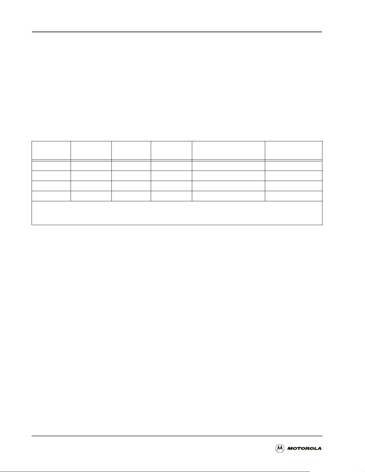
Internal Buses
1.4.6 On-Chip Memory
The memory space of the DSP56300 core is partitioned into program, X data, and Y data
memory space. The data memory space is divided into X and Y data memory in order to work
with the two address ALUs and to feed two operands simultaneously to the data ALU.
Memory space includes internal RAM and ROM and can be expanded off-chip under
software control. There is an on-chip 192/3K x 24-bit bootstrap ROM. For details on internal
memory, see Chapter 3, Memory Configuration. Program RAM, instruction cache, X data
RAM, and Y data RAM size are programmable, as Table 1-2 shows.
Table 1-2. DSP56301 Switch Memory Co nfiguration
Program
RAM Size
4096 × 24-bit 0 2048 × 24-bit 2048 × 24-bit disabled ( CE = 0) disabled (MS = 0)
3072 × 24-bit 1024 × 24-bit 2048 × 24-bit 2048 × 24-bit enabled (CE = 1) disabled (MS = 0)
2048 × 24-bit 0 3072 × 24-bit 3072 × 24-bit disabled (CE = 0) enabled (MS = 1)
1024 × 24-bit 1024 × 24-bit 3072 × 24-bit 3072 × 24-bit enabled (CE = 1) enabled (MS = 1)
1. Controlled by the Cache Enable (CE) bit in the Status Register (SR)
2. Controlled by the Memory Select (MS) bit in the Operating Mode Register (OMR)
Instruction
Cache Size
X Data RAM
Size
Y Data RAM
Size
Instruction Cache
1
Switch Mode
1.5 Internal Buses
All internal buses on the DSP56300 devices are 24-bit buses. To provide data exchange
between the blocks, the DSP56301 implements the following buses:
n Peripheral I/O expansion bus to peripherals
n X memory expansion bus to X memory
n Y memory expansion bus to Y memory
n Program data bus for carrying program data throughout the core
2
n X memory data bus for carrying X data throughout the core
n Y memory data bus for carrying Y data throughout the core
n Program address bus for carrying program memory addresses throughout the core
n X memory address bus for carrying X memory addresses throughout the core
n Y memory address bus for carrying Y memory addresses throughout the core.
1-10 DSP56301 User’s Manual
Page 27
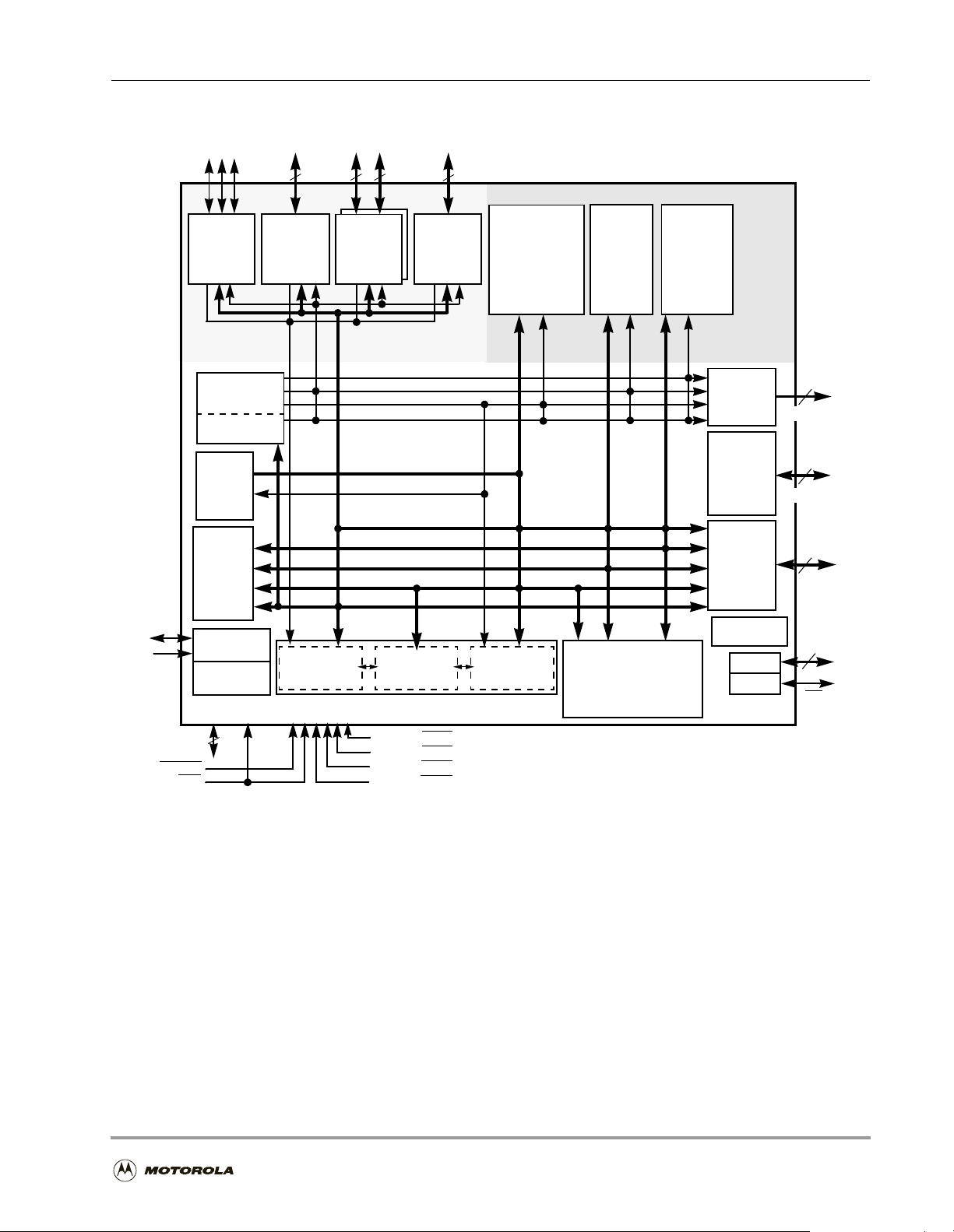
The block diagram in Figure 1-1 illustrates these buses among other components.
652
EXTAL
XTAL
Triple
Timer
Address
Generation
Unit
Six Channel
DMA Unit
Boot-
strap
ROM
Internal
Data
Bus
Switch
Clock
Generator
PLL
Host
Interface
(HI32)
Program
Interrupt
Controller
6
ESSI
Peripheral
Expansion Area
PIO_EB
3
SCI
Program
Decode
Controller
Memory Expansion Area
Program RAM
4096
(Default)
DSP56300
DDB
YDB
XDB
PDB
GDB
Program
Address
Generator
X Data
× 24
RAM
2048
× 24
(Default)
PM_EB
YAB
XM_EB
XAB
PAB
DAB
24-Bit
Core
Data ALU
× 24
+
MAC
24
Two 56-bit Accumulators
56-bit Barrel Shifter
Y Data
RAM
× 24
2048
(Default)
YM_EB
56 → 56-bit
External
Address
Bus
Switch
External
Bus
Interface
and
I - Cache
Control
External
Data Bus
Switch
Power
Management
JTAG
OnCE™
DMA
24
ADDRESS
14
CONTROL
24
DA T A
5
DE
2
RESET
PINIT/NMI
MODD/IRQA
MODC/
IRQB
MODB/IRQC
MODA/IRQD
Figure 1-1. DSP56301 Block Diagram
1.6 DMA
The DMA block has the following features:
n Six DMA channels supporting internal and external accesses
n One-, two-, and three-dimensional transfers (including circular buffering)
n End-of-block-transfer interrupts
n Triggering from interrupt lines and all peripherals
Overview 1-11
Page 28

Peripherals
1.7 Peripherals
In addition to the core features, the DSP56301 provides the following peripherals:
n As many as 42 user-configurable General-Purpose Input/Output (GPIO) signals
n Host Interface (HI32)
n Dual Enhanced Synchronous Serial Interfaces (ESSI0 and ESSI1)
n Serial Communications Interface (SCI)
n Triple timer module
1.7.1 General-Purpose Input/O utput (GPIO ) signals
The GPIO port consists of as many as 42 programmable signals, all of which are also used by
the peripherals (HI32, ESSI, SCI, and timer). There are no dedicated GPIO signals. After a
reset, the signals are automatically configured as GPIO. Three memory-mapped registers per
peripheral control GPIO functionality. Programming techniques for these registers to control
GPIO functionality are detailed in Chapter 5, Programming the Peripherals.
1.7.2 Host Interface (HI32)
The Host Interface (HI32) is a fast parallel host port up to 32 bits wide that can directly
connect to the host bus. The HI32 supports a variety of standard buses and provides glueless
connection with a number of industry-standard microcomputers, microprocessors, DSPs, and
DMA controllers. In one of its modes of operation, PCI mode, the HI32 is a dedicated
bidirectional target (slave) / initiator (master) parallel port with a 32-bit wide data path up to
eight words deep. The HI32 can connect directly to the PCI bus.
1.7.3 Enhance Synchronous Serial Interface (ESSI)
The DSP56301 provides two independent and identical ESSIs. Each ESSI has a full-duplex
serial port for communication with a variety of serial devices, including one or more
industry-standard CODECs, other DSPs, microprocessors, and peripherals that implement the
Motorola Serial Peripheral Interface (SPI). The ESSI consists of independent transmitter and
receiver sections and a common ESSI clock generator. ESSI capabilities include:
n Independent (asynchronous) or shared (synchronous) transmit and receive sections
with separate or shared internal/external clocks and frame syncs
n Normal mode operation using frame sync
n Network mode operation with as many as 32 time slots
n Programmable word length (8, 12, 16, 24, or 32 bits)
n Program options for frame synchronization and clock generation
n One receiver and three transmitters per ESSI
1-12 DSP56301 User’s Manual
Page 29

Peripherals
1.7.4 Serial Communications Interface (SCI)
The SCI provides a full-duplex port for serial communications with other DSPs,
microprocessors, or peripherals such as modems. The SCI interfaces without additional logic
to peripherals that use TTL-level signals. With a small amount of additional logic, the SCI can
connect to peripheral interfaces that have non-TTL level signals, such as the RS-232C,
RS-422, and so forth. This interface uses three dedicated signals: transmit data, receive data,
and SCI serial clock. It supports industry-standard asynchronous bit rates and protocols, as
well as high-speed synchronous data transmission (up to 12.5 Mbps for a 100 MHz clock).
SCI asynchronous protocols include a multidrop mode for master/slave operation with
wakeup on idle line and wakeup on address bit capability. This mode allows the DSP56301 to
share a single serial line efficiently with other peripherals.
Separate SCI transmit and receive sections can operate asynchronously with respect to each
other. A programmable baud-rate generator provides the transmit and receive clocks. An
enable vector and an interrupt vector allow the baud-rate generator to function as a
general-purpose timer when the SCI is not using it or when the interrupt timing is the same as
that used by the SCI.
1.7.5 Triple Timer Module
The triple timer module is composed of a common 21-bit prescaler and three independent and
identical general-purpose 24-bit timer/event counters, each with its own memory-mapped
register set. Each timer has the following properties:
n A single signal that can function as a GPIO signal or as a timer signal
n Uses internal or external clocking and can interrupt the DSP after a specified number
of events (clocks) or signal an external device after counting internal events
n Connects to the external world through one bidirectional signal. When this signal is
configured as an input, the timer functions as an external event counter or measures the
external pulse width/signal period. When the signal is used as an output, the timer
functions as either a timer, a watchdog, or a pulse width modulator.
Overview 1-13
Page 30
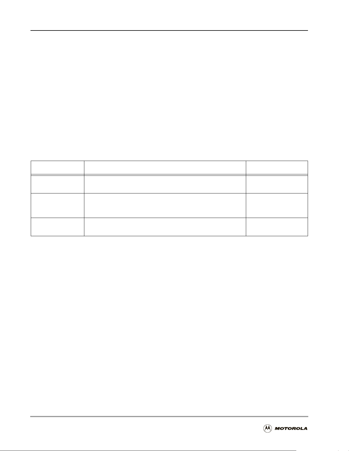
Related Documents and Web Sites
1.8 Related Documents and Web Sites
The documents listed in Table 1-3 are required for a complete description of the DSP56301
and are necessary to design properly with the part. Documentation is available from the
following sources (see back cover for detailed information):
n A local Motorola distributor
n A Motorola semiconductor sales office
n A Motorola Literature Distribution Center
n The World Wide Web (WWW)
Table 1-3. DSP 56301 Documentation
Name Description Order Number
DSP56300 Family
Manual
DSP56301 User’s
Manual
(this manual)
DSP56301
Technical Data
Detailed description of the DSP56300 family processor core and
instruction set
Detailed functional description of the DSP56301 memory
configuration, operation, and register programming
DSP56301 features list and physical, electrical, timing, and package
specifications
DSP56300FM/AD
DSP56301UM/AD
DSP56301/D
You can download these documents and other related documentation (all in pdf format)
referenced by the product page at:
http://www.mot.com/SPS/DSP/
For printed copies, contact the Literature Distribution Center at the number(s) provided on the
back cover of this manual.
1-14 DSP56301 User’s Manual
Page 31

Chapter 2
Signals/Connections
The DSP56301 input and output signals are organized into functional groups, as shown in
Table 2-1. Two different configurations are illustrated in Figure 2-1 and Figure 2-2. The
difference between these two configurations is the host port functionality. Although the
DSP56301 operates from a 3.3 volt supply, some of the input pins can tolerate 5 volts. A
special notice for this feature is added to the description of these pins.
Table 2-1. DSP56301 Functional Signal Groupings
Functional Group
Power (V
Ground (GND) 26 Table 2-3
Clock 2 Table 2-4
Phase-Lock Loop (PLL) 3 Table 2-5
Address bus
Data bus 24 Table 2-7
Bus control 15 Table 2-8
Interrupt and mode control 5 Table 2-9
Host Interface (HI32) Port B
Enhanced Synchronous Serial Interfaces (ESSI0 and
ESSI1)
Serial Communications Interface (SCI) Port E
Timers
JTAG/OnCE Port 6 Table 2-17
Notes: 1. Port A signals define the external memory interface port, including the external address bus, data bus, and
) 25 Table 2-2
CC
1
Port A
2
Ports C and D
5
control signals. The data bus lines have internal keepers.
2. Port B signals are the HI32 port signals multiplexed with the GPIO signals.
3. Port C and D signals are the two ESSI port signals multiplexed with the GPIO signals. All Port C and D
signals have keepers.
4. Port E signals are the SCI port signals multiplexed with the GPIO signals. All Port E signals have keepers.
5. All timer signals have keepers.
3
4
Number of
Signals
24 Table 2-6
52 Table 2-11
12 Table 2-13 and
3 Table 2-15
3 Table 2-16
Detailed
Description
Table 2-12
Table 2-14
Signals/Connections 2-1
Page 32

V
CCP
V
CCQ
V
CCA
V
CCD
V
CCC
V
CCH
V
CCS
GND
GND
GND
GND
GND
GND
GND
GND
EXTAL
XTAL
CLKOUT
PCAP
PINIT
A[0–23]
D[0–23]
AA[0–3]/
–3]
RAS[0
RD
WR
BS
BR
BG
BB
CAS
BCLK
BCLK
1P
TA
BL
DSP56301
Power Inputs:
PLL
4
Internal Logic
6
Address Bus
4
Data Bus
2
Bus Control
6
HI32
2
ESSI/SCI/Timer
Grounds:
4
6
4
2
6
2
PLL
PLL
Internal Logic
Address Bus
Data Bus
Bus Control
HI32
ESSI/SCI/Timer
Clock
PLL
Extended Synchronous
Serial Interface Port 0
Synchronous Serial
P
Q
A
D
N
H
S
Port A
24
External
Address Bus
24
External
Data Bus
4
External
Bus
Control
Interface (SCI) Port
Interrupt/
Mode
Control
Host
Interface
(HI32) Port
(ESSI0)
Extended
Interface Port 1
(ESSI1)
Serial
Communications
Timers
JTAG/OnCE
Port
1
2
2
2
3
MODA/IRQA
MODB/IRQB
MODC/IRQC
MODD/IRQD
RESET
NMI
Universal
PCI Bus
52
See Figure 2-2 for a listing of the Host
Bus
Interface/Port B Signals
Port C GPIO
PC[0–2]
PC3
PC4
PC5
Port D GPIO
PD[0–2]
PD3
PD4
PD5
Port E GPIO
PE0
PE1
PE2
Timer GPIO
TIO0
TIO1
TIO2
3
3
SC0[0–2]
SCK0
SRD0
STD0
SC1[0–2]
SCK1
SRD1
STD1
RXD
TXD
SCLK
TIO0
TIO1
TIO2
TCK
TDI
TDO
TMS
TRST
DE
Port B
GPIO
Notes: 1. The HI32 port supports PCI and non-PCI bus configurations. Twenty-four of these HI32 signals can
also be configured alternately as GPIO signals (PB[0–23]).
2. The ESSI0, ESSI1, and SCI signals are multiplexed with the Port C GPIO signals (PC[0–5] ), Port D
GPIO signals (PD[0–5]), and Port E GPIO signals (PE[0–2]), respectively.
3. TIO[0–2] can be configured as GPIO signals.
Figure 2-1. Signals Identified by Functional Group
2-2 DSP56301 User’s Manual
Page 33

DSP56301
Host Interface
(HI32)
Port B Signals
PCI Bus Universal Bus Port B GPIO Host Port (HP)
Reference
HAD0
HAD1
HAD2
HAD3
HAD4
HAD5
HAD6
HAD7
HAD8
HAD9
HAD10
HAD11
HAD12
HAD13
HAD14
HAD15
HC0/HBE0
HC1/HBE1
HC2/HBE2
HC3/HBE3
HTRDY
HIRDY
HDEVSEL
HLOCK
HPAR
HPERR
HGNT
HREQ
HSERR
HSTOP
HIDSEL
HFRAME
HCLK
HAD16
HAD17
HAD18
HAD19
HAD20
HAD21
HAD22
HAD23
HAD24
HAD25
HAD26
HAD27
HAD28
HAD29
HAD30
HAD31
HRST
HINTA
PVCL
HA3
HA4
HA5
HA6
HA7
HA8
HA9
HA10
HD0
HD1
HD2
HD3
HD4
HD5
HD6
HD7
HA0
HA1
HA2
Tie to pull-up or V
HDBEN
HDBDR
HSAK
HBS
HDAK
HDRQ
HAEN
HTA
HIRQ
HWR/HRW
HRD/HDS
Tie to pull-up or V
Tie to pull-up or V
HD8
HD9
HD10
HD11
HD12
HD13
HD14
HD15
HD16
HD17
HD18
HD19
HD20
HD21
HD22
HD23
HRST
HINTA
Leave unconnected
PB0
PB1
PB2
PB3
PB4
PB5
PB6
PB7
PB8
PB9
PB10
PB11
PB12
PB13
PB14
PB15
PB16
PB17
PB18
PB19
CC
PB20
PB21
PB22
PB23
Internal disconnect
Internal disconnect
Internal disconnect
Internal disconnect
Internal disconnect
Internal disconnect
Internal disconnect
CC
CC
Internal disconnect
Internal disconnect
Internal disconnect
Internal disconnect
Internal disconnect
Internal disconnect
Internal disconnect
Internal disconnect
Internal disconnect
Internal disconnect
Internal disconnect
Internal disconnect
Internal disconnect
Internal disconnect
Internal disconnect
Internal disconnect
Internal disconnect
Internal disconnect
Leave unconnected
HP0
HP1
HP2
HP3
HP4
HP5
HP6
HP7
HP8
HP9
HP10
HP11
HP12
HP13
HP14
HP15
HP16
HP17
HP18
HP19
HP20
HP21
HP22
HP23
HP24
HP25
HP26
HP27
HP28
HP29
HP30
HP31
HP32
HP33
HP34
HP35
HP36
HP37
HP38
HP39
HP40
HP41
HP42
HP43
HP44
HP45
HP46
HP47
HP48
HP49
HP50
PVCL
Note: HPxx is a reference only and is not a signal name. GPIO references formerly designated as HIOxx
have been renamed PBxx for consistency with other Motorola DSPs.
Figure 2-2. Host Interface /Port B Detail Signal Diagram
Signals/Connections 2-3
Page 34

Power
2.1 Power
Table 2-2. Power Inputs
Power
Name
V
CCP
V
CCQL
V
CCQH
V
CCA
V
CCD
V
CCC
V
CCH
V
CCS
PLL Power—VCC dedicated for PLL use. The voltag e should be well -regulated an d the input sh ould be provided
with an extremely low impedance path to the V
Quiet Core (Low) Power—An isolated power for the core processing logic. This input must be isolated
externally from all other chip power inputs. The user must provide adequate external decoupling capacitors.
Quiet External (High) Power—A quiet power source for I/O lines. This input must be tied externally to all other
chip power inputs. The user must provide adequate decoupling capacitors.
Address Bus Power—An isolated power for sections of the address bus I/O drivers. This input must be tied
externally to all other chip power inputs. The user must provide adequate external decoupling capacitors.
Data Bus Power—An isolated power for sections of the data bus I/O drivers. This input must be tied externally
to all other chip power inputs. The user must provide adequate external decoupling capacitors.
Bus Control Power—An isolated power for the bus control I/O drivers. This input must be tied externally to all
other chip power inputs. The user must provide adequate external decoupling capacitors.
Host Power—An isolated power for the HI32 I/O drivers. This input must be tied externally to all other chip
power inputs. The user must provide adequate external decoupling capacitors.
ESSI, SCI, and Timer Power—An isolated power for the ESSI, SCI, and timer I/O drivers. This input must be
tied externally to all other chip power inputs. The user must provide adequate external decoupling capacitors.
Description
power rail.
CC
2.2 Ground
Table 2-3. Ground Signals
Ground
Name
GND
GNDP1PLL Ground 1—GND dedicated for PLL use. The connection should be provided with an extremely
GNDQ Quiet Ground—An isolated ground for the internal processing logic. This connection must be tied externally to
GNDAAddress Bus Ground—An iso lated ground for secti ons of the a ddress bus I/O driv ers. T his con necti on m ust be
GND
GNDNBus Control Ground—An isolated gr ound for the bus control I/O drivers. This co nnection must be tied
GNDHHost Ground—An isolated ground for the HI32 I/O drivers. This connection must be tied externally to all other
GNDS ESSI, SCI, and Timer Ground—An isolated ground for the ESSI, SCI, and timer I/O drivers. This connection
PLL Ground— GND dedicated for PLL use. The connection should be provided with an extremely
P
low-impedance path to ground. V
possible to the chip package.
low-impedance path to ground.
all other chip ground connections. The user must provide adequate external decoupling capacitors.
tied externally to all other chip ground connections. The user must provide adequate external decoupling
capacitors.
Data Bus Ground—An isolated ground for sections of the data bus I/O drivers. This connection must be tied
D
externally to all ot her chi p ground conne ction s. The us er must pro vide a dequate extern al dec ouplin g capa citors .
externally to all ot her chi p ground conne ction s. The us er must pro vide a dequate extern al dec ouplin g capa citors .
chip ground connections. The user must provide adequate external decoupling capacitors.
must be tied externally to all other chip ground connections. The user must provide adequate external
decoupling capacitors.
should be bypassed to GNDP by a 0.47 µF capacitor located as close as
CCP
Description
2-4 DSP56301 User’s Manual
Page 35

2.3 Clock
Clock
Table 2-4. Clock Signals
Signal
Name
EXTAL Input Input External Clock/Crystal Input—Interfaces the internal crystal oscillator
XTAL Output Chip-driven Crystal Output—Connects the internal crystal oscillator output to an
Type
State During
Reset
Signal Description
input to an external crystal or an external clock.
external crystal. If an external clock is used, leave XTAL unconnected.
2.4 PLL
Table 2-5. Phase-Lock Loop Signals
Signal Name Type
PCAP Input Input PLL Capacitor—Connects an off-chip capacitor to the PLL filter.
CLKOUT Output Chip-driven Clock Output—An output clock synchronized to the internal core
PINIT Input Input PLL Initial—During assertion of
State During
Reset
Signal Description
Connect one capacitor terminal to PCAP and the other terminal to
V
.
CCP
If the PLL is not used, PCAP may be tied to VCC, GND, or left
floating.
clock phase.
Note: If the PLL is enabled and both the multiplication and division
factors equal one, then CLKOUT is also synchronized to EXTAL. If
the PLL is disabled, the CLKOUT frequency is half the frequency of
EXTAL.
RESET, the value of PINIT is
written into the PLL enable (PEN) bit of the PLL control (PCTL)
register, determining whether the PLL is enabled or disabled.
Signals/Connections 2-5
Page 36

External Memory Expansion Port (Port A)
2.5 External Memory Expansion Port (Port A)
When the DSP56301 enters a low-power standby mode (stop or wait), it releases bus
mastership and tri-states the relevant Port A signals:
RD, WR, BB, CAS, BCLK, BCLK.
2.5.1 External Address Bus
Table 2-6. External Address Bus Signals
A[0–23], D[0–23], AA0/RAS0–AA3/RAS3,
Signal Name Type
A[0–23] Output Tri-stated Address Bus—When the DSP is the bus master, A[0–23] are
State During
Reset
Signal Description
active-high outputs th at s pe cify th e a ddre ss fo r ex tern al p rog ram
and data memory accesses . Otherwise, the signals are tri-state d.
To minimize power dissipation, A[0–23] do not change state
when external memory spaces are not being accessed.
2.5.2 External Data Bus
.
Signal Name Type
D[0–23] Input/ Output Tri-stated Data Bus—When the DSP is the bus master, D0–D23 are
Notes: 1. One pin is reserved for use in the expansion port interface and the peripherals interface. Leave this pin
unconnected.
Table 2-7. External Data Bus Signals
State During
Reset
active-high, bidirectional input/outputs that provide the
bidirectional data bus for external program and data memory
accesses. Otherwise, D[0–23] are tri-stated. These lines have
weak keepers to maintain the last state even if all drivers are
tri-stated.
Signal Description
2.5.3 External Bus Control
Table 2-8. External Bus Control Signals
Signal
Name
AA[0–3]
RAS[0–3]
Type
Output
Output
2-6 DSP56301 User’s Manual
State During
Reset
Tri-stated
Tri-stated
Signal Description
Address Attribute—When defined as AA, these signals can be used as chip
selects or additional address lines. The default use defines a priority scheme
under which only one AA signal can be asserted at a time. Setting the AA priority
disable (APD) bit (Bit 14) of the OMR, the priority mechanism is disabled and the
lines can be used together as four external lines that can be decoded externally
into 16 chip select signals.
Row Address Strobe—When defined as RAS
for DRAM interface. These signals are tri-statable outputs with
RAS
programmable polarity.
, these signals can be used as
Page 37

External Memory Expansion Port (Port A)
Table 2-8. External Bus Control Signals (Continued)
Signal
Name
RD Output Tri-stated Read—When the DSP is the bus master, RD is an active-low output that is
WR Output Tri-stated Write—When the DSP is the bus master, WR is an active-low output that is
BS Output Tri-stated Bus Strobe — When the DSP is the bus master, BS
TA Input Ignored Input Transfer Acknowledge—If the DSP56301 is the bus master and there is no
Type
State During
Reset
Signal Description
asserted to read external memory on the data bus (D0–D23). Otherwise, RD
tri-stated.
asserted to write external memory on the data bus (D0–D23). Otherwise, the
signals are tri-stated.
is asserted for half a clock
cycle at the start of a bus cycle to provide an “early bus start” signal for a bus
controller. If the external bus is not used during an instruction cycle, BS remains
deasserted until the next external bus cycle.
external bus activity, or the DSP56301 is not the bus master, the TA
ignored. The TA
extend an external bus cycle indefinitely. Any number of wait states (1,
2. . .infinity) may be added to the wait states inserted by the bus control register
(BCR) by keeping TA
start of a bus cycle, is asserted to enable completion of the bus cycle, and is
deasserted before the nex t bus c yc le. The c urre nt bu s c yc le co mpletes one clock
period after TA
determined by the
used to set the minimum number of wait states in external bus cycles.
To use the TA
state. A zero wait sta te a ccess c annot be ex tended by TA
improper operation may result .
depending on the setting of the OMR[TAS] bit. TA
while DRAM accesses are performed; otherwise, improper operation may result.
input is a data transfer acknowledge (DTACK) function that can
deasserted. In typical operation, TA is deasser ted at the
is asserted synchronous to CLKOUT. T he number of w ait states is
TA input or by the BCR, whichever is longer. The BCR can be
functionality, the BCR must be programmed to at least one wait
deassertion; otherwis e,
TA can operate sync hronou sly or as ynch ronous ly
functionality must not be used
input is
is
BR
Output Output
(deasserted)
Note: For operations that do not use the TA
Bus Request—Asserted when the DSP reque sts bus mastersh ip and de asserted
when the DSP no longer needs the bus. BR
independently of whether the DSP56301 is a bus master or a bus slave. Bus
“parking” allows BR to be deasserted even though the DSP56301 is the bus
master. (See the description of bus “parking” in the BB
bus request hold (BRH) bit in the BCR allows BR
control even though the DSP does not need the bus. BR
external bus arbitrator that controls the priority, parking, and tenure of each
master on the same external bus. BR is affected only by DSP requests for the
external bus, never for the internal bus. During hardware reset, BR
and the arbitration is reset to the bus slave state.
bus control function, pull this pin low.
is asserted or deasserted
signal description.) The
to be asserted under software
is typically sent to an
is deasserted
Signals/Connections 2-7
Page 38

External Memory Expansion Port (Port A)
Table 2-8. External Bus Control Signals (Continued)
Signal
Name
BG Input Ignored Input Bus G rant —Asserted/deasserted synchronous to CLKOUT for proper operation,
BB
Type
Input/
Output
State During
Reset
is asserted by an external bus arbitration circuit when the DSP56301
BG
becomes the next bus master. When BG
until BB
mastership is typically given up at the end of the current bus cycle. This may
occur in the middle of an instruction that requires more than one external bus
cycle for execution.
The default operation of this bit requires a setup and hold time as specified in
is deasserted before taking bus mas tership. Wh en BG is deasserted, bus
DSP56301 Technical Data
set the asynchronous bus arbitration enable (ABE) bit (Bit 13) in the OMR. When
this bit is set, BG
respective setup and hold time requirements but adds a required delay between
the deassertion of an initial BG input and the assertion of a subsequent BG input.
Note: For operations that do not us e th e BG bus control function, pull this pin low.
Input Bus Busy—Asserted and deassert ed synchronous to CLKOUT, BB in dicates that
the bus is active. Only after BB
become the bus master (and then assert the signal again). The bus master can
keep BB
or deasserted. Such “bus pa rki ng” all ow s the cu rrent bus master to reuse the bus
without rearbitration until another device requires the bus. BB is deasserted by an
“active pull-up” method (that is, BB
by an external pull-up resistor).
asserted after ceasing bus activity regardless of whether BR is asserted
and BB are synchronized internally. This eliminates the
Signal Description
is asserted, the DSP56301 must wait
(the data sheet). An alternate mode can be invoked:
is deasserted can the pending bus master
is driven high a nd then releas ed an d held high
The default operation of this bit requires a setup and hold time as specified in the
DSP56301 Technical Data sheet
bit (Bit 13) in the OMR. When this bit is set, BG
internally. See BG
Note: BB requires an external pull-up resistor.
BL
CAS Output Tri-stated Column Address Strobe—When the DSP is the bus master, DRAM uses CAS
BCLK Output Tri-stated Bus Clock—When the DSP is the bus master, BCLK is active as a sampling
BCLK
Output Never
tri-stated;
deasserted
Output Tri-stated Bus Clock Not—When the DSP is the bus master, BCLK is the inverse of the
Bus Lock— Asserted at the start of an external indivisible Read-Modify-Write
(RMW) bus cycle and deasserted at the end of the write bus cycle. BL
asserted between the read and write bus cycles of the RMW bus sequence. BL
can be used to “resource lock” an external multi-port memory for secure
semaphore updates. The only instructi ons that au tomatically assert BL are BSET,
BCLR, or BCHG, which accesses external memory. BL
setting the BLH bit in the BCR register.
to strobe the column address. Otherwise, if the bus mastership enable (BME) bit
in the DRAM control register is cleared, the signal is tri-stated.
signal when the program address tracing mode is enabled (that is, the ATE bit in
the OMR is set). When BCLK is active and synchronized to CLKOUT by the
internal PLL, BCLK precedes CLKOUT by one-fourth of a clock cycle. The BCLK
rising edge can be used to sample the internal program memory access on the
A[0–23] address lines.
BCLK signal. Otherwise, the signal is tri-stated.
for additional information.
. An alternate mode can be invoked: se t the ABE
and BB are synchronized
remains
can also be asserted by
2-8 DSP56301 User’s Manual
Page 39

Interrupt and Mode Control
2.6 Interrupt and Mode Control
The interrupt and mode control signals select the chip’s operating mode as it comes out of
hardware reset. After
RESET is deasserted, these inputs are hardware interrupt request lines.
Table 2-9. Interrupt and Mode Control
Signal
Name
RESET
MODA
IRQA
MODB
IRQB
MODC
Type
Input,
Schmitttrigger
Input,
Schmitttrigger
Input
Input,
Schmitttrigger
Input
Input,
Schmitttrigger
State
During
Reset
Input Reset—Must be assert ed at power up. Deasse rtion of RESET is in ternally sync hronized
to CLKOUT. When asserted, the chip goes into the Reset state and the internal phase
generator is reset. The Schmitt-trigger allows a slowly rising input (such as aa charging
capacitor) to reset the chip reliably. If RESET
exact start-up timing is guaranteed, allowing multiple processors to start synchronously
and operate together in
operating mode from the MODA–MODD inputs. This input is 5 V tolerant.
Input Mode Select A—Internally synchronized to CLKOUT. MODA, MODB, MODC, and
MODD select one of 16 initial chip operating modes, latched into the OMR when the
RESET signal is deasserted.
External Interrupt Request A—After reset, this input becomes a level-sens itive or
negative-edge-triggered, maskable interrupt request input during normal instruction
processing. If IRQA
resynchronized using the WAIT instruction and asserting IRQA
the processor is in the stop standby state and IRQA
stop state.
Input Mode Select B—Internally synchronized to CLKOUT. MODA, MODB, MODC, and
MODD select one of 16 initial chip operating modes, latched into the OMR when the
signal is deasserted.
RESET
External Interrupt Request B—After reset, this input becomes a level-sens itive or
negative-edge-triggered, maskable interrupt request input during normal instruction
processing. If IRQB is asserted sy nchronous t o CLKOUT, multiple proc essors can be
resynchronized using the WAIT instruction and asserting IRQB
Input Mode Select C—Internally synchronized to CLKOUT. MODA, MODB, MODC, and
MODD select one of 16 initial chip operating modes, latched into the OMR when the
signal is deasserted.
RESET
lock-step
is asserted synchronous to CLKOUT, multiple processors can be
Signal Description
is deasserted synchronous to CLKOUT,
. Deasserting the RESET signal latches the initial chip
to exit the wait state. If
is asserted, the processor exits the
to exit the wait state.
IRQC
MODD
IRQD
NMI
Input
Input,
Schmitttrigger
Input
Input,
Schmitttrigger
External Interrupt Request C—After reset, this input becomes a level-sens itive or
negative-edge-triggered, maskable interrupt request input during normal instruction
processing. If IRQC is asserted synchronous to CLKOUT, multiple processors can be
resynchronized using the WAIT instruction and asserting IRQC
Input Mode Select D—Internally synchronized to CLKOUT. MODA, MODB, MODC, and
MODD select one of 16 initial chip operating modes, latched into the OMR when the
signal is deasserted.
RESET
External Interrupt Request D—After reset, this input becomes a level-sens itive or
negative-edge-triggered, maskable interrupt request input during normal instruction
processing. If IRQD is asserted synchronous to CLKOUT, multiple processors can be
resynchronized using the WAIT instruction and asserting IRQD
Input Nonmaskable Interrupt—After RESET
processing, the negative-edge-triggered NMI request is internally synchronized to
CLKOUT.
Signals/Connections 2-9
deassertion and during normal instruction
to exit the wait state.
to exit the wait state.
Page 40

Host Interface (HI32)
2.7 Host Interface (HI32)
The Host Interface (HI32) provides a fast parallel data port up to 32 bits wide that can connect
directly to the host bus. The HI32 supports a variety of standard buses and provides glueless
connection with the PCI bus standard and with a number of industry-standard
microcomputers, microprocessors, DSPs and DMA hardware. The functions of the signals
associated with the HI32 vary according to the programmed configuration of the interface as
determined by the 24-bit DSP Control Register (DCTR). Refer to Chapter 6, Host Interface
(HI32) for detailed descriptions of this and other HI32 configuration registers.
Note: All HI32 inputs are 5 V tolerant.
Table 2-10. Host Interface
Signal Name Type
HAD[0–7]
HA[3–10]
PB[0–7]
HAD[15–8]
HD[7–0]
PB[15–8]
Input/Output
Input/Output
Input/Output
Input
Input or
Output
Input or
Output
State During
Reset
Tri-stated Host Address/Data 0–7—When the HI3 2 is programme d to
interface with a PCI bus and the HI function is selected, these
signals are lines 0–7 of the bidirectional, multiplexed Address/Data
bus.
Host Address 3–10—When HI32 is programmed to in terface with a
universal non-PCI b us and the HI function is selected, these signals
are lines 3–10 of the input Address bus.
Port B 0–7—When the HI32 is configured as GPIO through the
DCTR, these signals are individually programmed as inputs or
outputs through the HI32 Data Direction Register (DIRH).
Tri-stated Host Address/Data 8–15—When the HI32 is programmed to
interface with a PCI bus and the HI function is selected, these
signals are lines15–8 of the bidirectional, multiplexed Address/Data
bus.
Host Data 0–7—When the HI32 is programmed to interface wit h a
universal non-PCI b us and the HI function is selected, these signals
are lines 7–0 of the bidirectional Data bus.
Port B 8–15—When the HI32 is configured as GPIO through the
DCTR, these signals are individually programmed as inputs or
outputs through the HI32 DIRH.
Signal Description
2-10 DSP56301 User’s Manual
Page 41

Table 2-10. Host Interface (Continued)
Host Interface (HI32)
Signal Name Type
HC0–HC3/
HBE[3–0]
HA[2–0]
PB[19–16]
HTRDY
HDBEN
PB20
Input/Output
Input
Input or
Output
Input/
Output
Output
Input or
Output
State During
Reset
Tri-stated Command 0–3/Byte Enable 0–3—When the HI32 is programmed
to interface with a PCI bus and the HI function is selected, these
signals are lines7–0 of the bidirectional, multiplexed Address/Data
bus.
Host Address 0–2—When the HI32 is programmed to interface
with a universal non-PCI bus and the HI function is selected, these
signals are lines 2–0 of the input Address bus.
The fourth signal in this set sho uld be co nnecte d to a pull -up resist or
or directly to V
Port B 16–19—When the HI32 is configured as GPIO through the
DCTR, these signals are individually programmed as inputs or
outputs through the HI32 DIRH.
Tri-stated Host Target Ready—When the HI32 is programmed to interface
with a PCI bus and the HI function is selected, this is the Host
Target Ready signal.
Host Data Bus Enable—When HI32 is programmed to interface
with a universal non-PCI bus and the HI function is selected, this
signal is Host Data Bus Enable output.
Port B 20—When the HI32 is configured as GPIO through the
DCTR, this signal is individually programmed as an input or output
through the HI32 DIRH.
CC
Signal Description
when a non-PCI bus is used.
HIRDY
HDBDR
PB21
HDEVSEL
HSAK
PB22
Input/
Output
Output
Input or
Output
Input/
Output
Output
Input or
Output
Tri-stated Host Initiator Ready—When the HI32 is programmed to interface
with a PCI bus and the HI function is selected, this is the Host
Initiator Ready signal.
Host Data Bus Direction—When HI32 is programmed to interface
with a universal non-PCI bus and the HI function is selected, this
signal is Host Data Bus Direction output.
Port B 21—When the HI32 is configured as GPIO through the
DCTR, this signal is individually programmed as an input or output
through the HI32 DIRH.
Tri-stated Host Device Select—When the HI32 is programmed to interface
with a PCI bus and the HI function is selected, this is the Host
Device Select signal.
Host Select Acknowledge—When HI32 is programmed to
interface with a universal non-PCI bus and the HI function is
selected, this signal is Host Select Acknowledge output.
Port B 22—When the HI32 is configured as GPIO through the
DCTR, this signal is individually programmed as an input or output
through the HI32 DIRH.
Signals/Connections 2-11
Page 42

Host Interface (HI32)
Table 2-10. Host Interface (Continued)
Signal Name Type
HLOCK
HBS
PB23
HPAR
HDAK
HPERR
Input/
Output
Input
Input or
Output
Input/
Output
Input
Input/
Output
State During
Reset
Tri-stated Host Lock—When the HI32 is programmed to interface with a PCI
bus and the HI function is selected, this is the Host Lock signal.
Host Bus Strobe—When HI32 is programmed to interface with a
universal non-PCI bus and the HI function is selected, this signal is
Host Bus Strobe Schmitt-trigger input.
Port B 23—When the HI32 is configured as GPIO through the
DCTR, this signal is individually programmed as an input or output
through the HI32 DIRH.
Tri-stated Host Parity—When the H I32 i s pro gram m ed to i nterface with a PCI
bus and the HI function is selected, this is the Host Parity signal.
Host DMA Acknowledge—When HI32 is programmed to interface
with a universal non-PCI bus and the HI function is selected, this
signal is Host DMA Acknowledge Schmitt-trigger input.
Port B —When the HI32 is configured as GPIO through the DCTR,
this signal is internally disconnected.
Tri-stated Host Parity Error—When the HI32 is programmed to int erface with
a PCI bus and the HI function is selected, this is the Host Parity
Error signal.
Signal Description
HDRQ
HGNT
HAEN
HREQ
HTA
Output
Input
Input
Output
Output
Host DMA Request—When HI32 is programmed to interface a with
universal non-PCI bus and the HI function is selected, this signal is
Host DMA Request output.
Port B —When the HI32 is configured as GPIO through the DCTR,
this signal is internally disconnected.
Input Host Bus Grant—When the HI32 is programmed to interface with a
PCI bus and the HI function is selected, this is the Host Bus Grant
signal.
Host Address Enable—When HI32 is programmed to i nterface
with a universal non-PCI bus and the HI function is selected, this
signal is Host Address Enable output.
Port B —When the HI32 is configured as GPIO through the DCTR,
this signal is internally disconnected.
Tri-stated Host Bus Request—When the HI32 is programmed to interface a
PCI bus and the H I functi on is sel ected, this is the Host Bus Re quest
signal.
Host Transfer Acknowledge—When HI32 is programmed to
interface with a universal non-PCI bus and the HI function is
selected, this signal is Host Data Bus Enable output.
Port B —When the HI32 is configured as GPIO through the DCTR,
this signal is internally disconnected.
2-12 DSP56301 User’s Manual
Page 43

Table 2-10. Host Interface (Continued)
Host Interface (HI32)
Signal Name Type
HSERR
HIRQ
HSTOP
HWR/HRW
HIDSEL
Output, open
Output, open
drain
drain
Input/
Output
Input
Input
State During
Reset
Tri-stated Host System Error—When the HI32 is programmed to interface
with a PCI bus and the HI function is selected, this is the Host
System Error signal.
Host Interrupt Request—When HI32 is programmed to interface
with a universal non-PCI bus and the HI function is selected, this
signal is Host Interrupt Request output.
Port B —When the HI32 is configured as GPIO through the DCTR,
this signal is internally disconnected.
Tri-stated Host Stop—When the HI32 is programmed to interface with a PCI
bus and the HI function is selected, this is the Host Stop signal.
Host Write/Host Read-Write—Wh en HI32 is program m ed to
interface with a universal non-PCI bus and the HI function is
selected, this signal is Host Write/Host Read-Write Schmitt-trigger
input.
Port B —When the HI32 is configured as GPIO through the DCTR,
this signal is internally disconnected.
Input Host Initialization Device Select—When the HI32 is programmed
to interface with a PCI bus and the HI func tion is selecte d, this is th e
Host Initialization Device Select signal.
Signal Description
HRD
/HDS
HFRAME
HCLK Input Input Host Clock—When the HI32 is programmed to interface with a PCI
Input
Input/
Output
Host Read/Host Data Strobe—When HI32 is programmed to
interface with a universal non-PCI bus and the HI function is
selected, this signal is Host Data Read/Host Data Strobe
Schmitt-trigger input.
Port B —When the HI32 is configured as GPIO through the DCTR,
this signal is internally disconnected.
Tri-stated Host Frame—When the HI32 is programmed t o interfac e with a PCI
bus and the HI function is selected, this is the Host cycle Frame
signal.
Non-PCI bus—When HI32 is programmed to interface with a
universal non-PCI bus and the HI function is selected, this signal
must be connected to a pull-up resistor or directly to V
Port B —When the HI32 is configured as GPIO through the DCTR,
this signal is internally disconnected.
bus and the HI function is selected, this is the Host Bus Clock input.
Non-PCI bus—When the HI32 is programmed to interface with a
universal non-PCI bus and the HI function is selected, this signal
must be connected to a pull-up resistor or directly to V
Port B —When the HI32 is configured as GPIO through the DCTR,
this signal is internally disconnected.
CC
CC
.
.
Signals/Connections 2-13
Page 44

Host Interface (HI32)
Table 2-10. Host Interface (Continued)
Signal Name Type
HAD[31–16]
HD[23–8]
HRST
HRST
HINTA Output, open
Input/Output
Input/Output
Input
Input
drain
State During
Reset
Tri-stated Host Address/Data 16–31—When the HI32 is programmed to
interface with a PCI bus and the HI function is selected, these
signals are lines 16–31 of the bidirectional, multiplexed
Address/Data bus.
Host Data 8–23—When the HI3 2 i s prog ram med to interface with a
universal non-PCI b us and the HI function is selected, these signals
are lines 8–23 of the bidirectional Data bus.
Port B —When the HI32 is configured as GPIO through the DCTR,
these signals are internally disconnected.
Tri-stated Hardware Reset—When the HI32 is programmed to interface with
a PCI bus and the HI functio n is s elected, thi s is th e Hardware R eset
input.
Hardware Reset—When the HI32 is programmed to interface with
a universal non-PCI bus and the HI function is selected, this signal
is the Hardware Reset Schmitt-trigger input.
Port B —When the HI32 is configured as GPIO through the DCTR,
this signal is internally disconnected.
Tri-stated Host Interrupt A—When the HI function is selected, this signal is
the Interrupt A open-drain output.
Signal Description
Port B —When the HI32 is configured as GPIO through the DCTR,
this signal is internally disconnected.
PVCL Input Input PCI Voltage Clamp—When the HI32 is programmed to interface
with a PCI bus and th e H I fun cti on is s ele cte d a nd the PC I b us us es
a 3 V signal environment, connect this pin to V
the high voltage clamping required by the PCI specifications. In all
other cases, in cl udi ng a 5 V PCI signal environme nt, le ave the input
unconnected.
(3.3 V) to enable
CC
Table 2-11. Summary of HI32 Signals and Modes
Signal
Name
HP0 HAD0 HA3 HIO0
HP1 HAD1 HA4 HIO1
HP2 HAD2 HA5 HIO2
HP3 HAD3 HA6 HIO3
HP4 HAD4 HA7 HIO4
HP5 HAD5 HA8 HIO5
HP6 HAD6 HA9 HIO6
PCI Mode Enhanced Universal Bus Mode Universal Bus Mode GPIO Mode
HP7 HAD7 HA10 HIO7
2-14 DSP56301 User’s Manual
Page 45

Host Interface (HI32)
Table 2-11. Summary of HI32 Si gnals and Modes ( Continued)
Signal
Name
HP8 HAD8 HD0 HIO8
HP9 HAD9 HD1 HIO9
HP10 HAD10 HD2 HIO10
HP11 HAD11 HD3 HIO11
HP12 HAD12 HD4 HIO12
HP13 HAD13 HD5 HIO13
HP14 HAD14 HD6 HIO14
HP15 HAD15 HD7 HIO15
HP16 HC0/HBE0 HA0 HIO16
HP17 HC1/HBE1 HA1 HIO17
HP18 HC2/HBE2 HA2 HIO18
HP19 HC3/HBE3 Unused (must be pulled up or down) HIO19
HP20 HTRDY HDBEN HIO20
HP21 HIRDY
HP22 HDEVSEL HSAK HIO22
PCI Mode Enhanced Universal Bus Mode Universal Bus Mode GPIO Mode
HDBDR HIO21
HP23 HLOCK
HP24 HPAR HDAK (Schmitt trigger buffer on input— pull
HP25 HPERR HDRQ disconnected
HP26 HGNT HAEN disconnected
HP27 HREQ HTA disconnected
HP28 HSERR HIRQ disconnected
HP29 HSTOP HWR/HRW (Schmitt trigger buffer on input) disconnected
HP30 HIDSEL HRD/HDS (Schmitt trigger buffer on input) disconnected
HP31 HFRAME Unused (must be pulled up) disconnected
HP32 HCLK Unused (must be pulled up)
HP33 HAD16 (pull up or down if no t used) HD8 disconnected
HP34 HAD17 (pull up or down if no t used) HD9 disconnected
HP35 HAD18 (pull up or down if no t used) HD10
HP36 HAD19 (pull up or down if no t used) HD11
HP37 HAD20 (pull up or down if no t used) HD12 disconnected
HP38 HAD21 (pull up or down if no t used) HD13
HBS (Schmitt trigger buffer o n input— pull up
if not used)
up if not used)
HIO23
disconnected
disconnected
disconnected
disconnected
HP39 HAD22 (pull up or down if no t used) HD14
Signals/Connections 2-15
disconnected
Page 46

Host Interface (HI32)
Table 2-11. Summary of HI32 Si gnals and Modes ( Continued)
Signal
Name
HP40 HAD23 (pull up or down if not used)
HP41 HAD24 (pull up or down if not used)
HP42 HAD25 (pull up or down if not used)
HP43 HAD26 (pull up or down if not used)
HP44 HAD27 (pull up or down if not used)
HP45 HAD28 (pull up or down if not used)
HP46 HAD29 (pull up or down if not used)
HP47 HAD30 (pull up or down if not used)
HP48 HAD31 (pull up or down if not used)
PCI Mode Enhanced Universal Bus Mode Universal Bus Mode GPIO Mode
1
1
1
1
1
1
1
1
1
HP49 HRST HRST (Schmitt trigger buffer on input)
HP50 HINTA
PVCL Leave unconnected
1. HD23-HD16 Output is high impedance if HRF
≠$0. Input is disconnected if HTF≠$0.
Table 2-12. Host Port Pins (HI32)
Signal
Name
PCI
Enhanced Universal Bus Mode GPIO
HD15 disconnected
HD16 disconnected
HD17 disconnected
HD18 disconnected
HD19 disconnected
HD20 disconnected
HD21 disconnected
HD22 disconnected
HD23 disconnected
Universal Bus Mode
HP[7–0] HAD[15–0]
Address/Data Multiplexed Bus
Tri-state bidirectional bus.
During the first clock cycle of a
transaction HAD31-HAD0 contain the
physical byte address (32 bits).
HP[15–8] HD[7–0]
During subsequent clock cycles,
HAD31-HAD0 contain data.
HA[10–3]
Host Address Bus
Input pin.
Selects HI32 register to access. HA[10–3]
select the HI32 and HA[2–0] select the
particular register of the HI32 to be accessed.
Host Data Bus
Tri-state, bidirecti onal bus.
Transfers data between the host processor
and the HI32.
This bus is released (disconnected) when the
HI32 is not selected by HA[10-0]. The
HD[23–0] pins are driv en by the HI32 d uring a
read access and are inpu ts to the HI32 d uring
a write access.
HD[23–16] outputs are high impedance if
HRF≠$0. HD[23–16] inputs are disconnected
if HTF≠$0.
HIO[15–8]
2
GPIO
2-16 DSP56301 User’s Manual
Page 47

Table 2-12. Host Port Pins (HI32) (Continued)
Host Interface (HI32)
Signal
Name
PCI
HP[18–16] HC3/HBE3–HC0/HBE0
Bus Command/Byte Enable
Tri-state bidirectional bus.
During the address phase of a
transaction, HC3/HBE3
define the bus command. During the
HP19
HC3/HBE3
data phase HC3/HBE3–HC0/HBE0
are used as byte enables. The byte
enables determine which byte lanes
carry meaningful data.
HP20 HTRDY
Host Target Ready
Sustained tri-state bidirectional pin.
Indicates the target agent’s ability to
complete the current data phase of
the transaction. HTRDY is used in
conjunction with HIRD Y
phase is completed on any clock both
HIRDY and HTRDY are sampled
asserted. HTRDY
is asserted if:
n during a data read valid data is
present on HAD31-HAD0
(HRRQ=1 in the HSTR).
n during a data write it indicates
the HI32 is ready to ac cept
data (HTRQ=1 in the HSTR).
n duri ng a vector write it indi cates
the HI32 is ready to ac cept a
new host command (HC=0 in
the HCVR).
Wait cycles are inserted until HIRDY
and HTRDY
are asserted together.
–HC0/HBE0
2
. When a data
Universal Bus Mode
Enhanced Universal Bus Mode GPIO
HA[2–0]
Host Address Bus
Input pin.
Selects HI32 register to access. HA[10–3]
select the HI32 and HA[2–0] select the
particular register of the HI32 to be accessed.
Reserved
Must be forced or pulled to V
or GND.
CC
HDBEN
Host Data Bus Enable
Output pin.
Asserted during HI32 ac cesses.
When asser ted the ext ernal (optional) data
transceiver outputs are enabled. When
deasserted the external transceiver outputs
are high impedance.
HIO[18–16]
2
GPIO
HIO19
2
GPIO
HIO20
2
GPIO
HP21 HIRDY
Host Initiator Ready
Sustained tri-state bidirectional pin.
Indicates the initiating agent’s ability
to complete the current data phase of
the transaction. Used with HTRDY.
When a data phase is completed on
any clock both HIRDY and HTRDY
are sampled asserte d. Wait cycles are
inserted until both HIR DY
are asserted together. The HI32
deasserts HIRDY if it cannot complete
the next data phase.
2
and HTRDY
Signals/Connections 2-17
HDBDR
Host Data Bus Direction
Output pin.
Driven high on write data trans fers and driven
low on read data transfers. This pin is
normally high.
HIO21
GPIO
2
Page 48

Host Interface (HI32)
Table 2-12. Host Port Pins (HI32) (Continued)
Signal
Name
HP22 HDEVSEL
Host Device Select
Sustained tri-state bidirectional pin.
When actively driven, indicates the
driving device has decoded its
address as a target of the current
access. As an input it indicates
whether any device on the bus is
selected.
HP23 HLOCK
Host Lock
Sustained tri-state bidirectional pin.
Indicates an atomic operation that
may require multiple transactions to
complete. When HLOCK is asserted,
non-exclusive transactions to the
HI32 are ‘re tried’ (that is, this is an
entire resource lock).
HP24 HPAR
Host Parity
Tri-state bidirectional pin.
Even parity across HAD[31–0] and
HC3/HBE3
drives HPAR during address and writ e
data phases; the target drives HPAR
during read data phases.
PCI
–HC0/HBE0. The master
Universal Bus Mode
Enhanced Universal Bus Mode GPIO
HSAK
Host Select Acknowledge
2
Active low output pin.
Acknowledges to the host processor that the
HI32 has identified its address as a slave.
HSAK is asserted when the HI32 is the
selected slave; otherwise HSAK is released.
HBS
Bus Strobe
2
Schmitt trigger input pin.
Asserted at the start of a bus cy c le (fo r hal f of
a clock cycle) providing an “early bus start”
signal. This enables the HI32 to respond
valid) earlier. HBS should be forced or
(HTA
pulled up to V
if not used (for example, ISA
CC
bus).
HDAK
Host DMA Acknowledge
Schmitt trigger input pin.
Indicates that the external DMA channel is
accessing the HI32. Th e HI32 is sele cted as a
DMA device if HDAK and HWR or HRD (in the
double-strobe mode) or HDAK and HDS (in
the single-strobe mode) are asserted. HDAK
should be forced or pulled up to V
used.
CC
if not
HI022
2
GPIO
HIO23
2
GPIO
disconnected
HP25 HPERR
Parity Error
Sustained tri-state bidirectional pin.
Used for reporting of data parity
errors. HPERR
(by the agent receiving data) two
clocks following the data (that is one
clock following the HPAR signal)
when a data parity error is detected.
must be driven active
HDRQ
DMA Request
2
Output Pin.
Supports ISA/EISA-type DMA data transfers.
The HI32 asserts HDRQ w hen a DMA requ est
(receive and/or transmit) is generated in the
HI32. HDRQ is deasserted when the DMA
request source is clea red (HDAK
masked (by RREQ=0 or T REQ=0) or disabl ed
(DMAE=0).
The polarity of HDRQ pin is controlled by
HDRP bit in the DCTR.
HP26 HGNT
Bus Grant
Input pin.
Indicates to the HI32 that it has
mastership of the bus. If not used, this
pin should be forced or pulled up to
Vcc.
HAEN
Host Address Enable
Input pin.
Enables ISA/EISA DMA / I/O type accesses.
When high, the HI32 responds to DMA cycles
only (if DMAE=1 in the DCTR; if DM AE=0, the
HI32 ignores the access). When low, the HI32
responds when it identifie s its add ress (tha t is
ISA/EISA DMA / I/O type-space accesses).
2-18 DSP56301 User’s Manual
disconnected
is asserted),
disconnected
Page 49

Table 2-12. Host Port Pins (HI32) (Continued)
Host Interface (HI32)
Signal
Name
HP27 HREQ
Bus Request
Tri-state, Output pin.
Indicates to the arbiter that the HI32
requires use of the bus.
HREQ
clock that the HI32 asserts HFRAME
As during the STOP reset HREQ
high impedance; an external pull-up
should be connec ted if it is connected
to the PCI bus arbiter.
HP28 HSERR
Host System Error
Open drain output pin
Reports address parity errors and
other errors where the result will be
catastrophic. Asserted for a single
PCI clock by the HI32.
PCI
is deasserted in the same PCI
is
1
.
Universal Bus Mode
Enhanced Universal Bus Mode GPIO
HTA
Host Transfer Acknowledge
Tri-state, Output pin.
For high speed data transfer between the
HI32 and an external hos t when the ho st uses
a non-interrupt driven h andshake mech anism.
.
If the HI32 deasserts HTA at the beginning of
the host access, the host should extend the
access as long as HTA is deasserted. The
polarity of the HTA pin is controlled by HTAP
in the DCTR.
The HTA pin is asserted if:
n du ring a data read vali d data is present
on HD23-HD0 (HRRQ=1 in the HSTR).
n du ring a data write it in dicat es the HI 32
is ready to accept data (HTRQ=1 in the
HSTR).
n during a vector write it indicat es the
HI32 is ready to accept a new host
command (HC=0 in the HCVR).
HIRQ
Host Interrupt Request
Output pin1.
Used by the HI32 to request service from the
host processor. HIRQ
an interrupt request pin of a host processo r, a
transfer request of a DMA controller or a
control input of external circuitry.
may be connected to
disconnected
disconnected
is initially asserted by the HI32 when an
HIRQ
interrupt request is enabled (TREQ=1 or
RREQ=1) and the corresponding data path is
ready for a data transfer.
If the HIRH bit in the DCTR is cleared: HIRQ
assertion is a pulse with a width controlled by
the CLAT register.
If HIRH is set: HIRQ
beginning of a corresponding host data
access (read or write), or masked (by
TREQ=0 or RREQ=0) or disabled (DMAE=1).
HIRQ is asserted again after the host access
(regardless of the HIRH v alue), if en abled and
the corresponding data path is ready for a
data transfer. The HIRQ
drain) is controlled by the HIRD bit in the
DCTR.
Signals/Connections 2-19
is deasserted at the
drive (driven or ope n
Page 50

Host Interface (HI32)
Table 2-12. Host Port Pins (HI32) (Continued)
Signal
Name
HP29 HSTOP
Host Stop
Sustained tri-state bidirectional pin.
Indicates that the current target is
requesting the master to stop the
current transaction.
HP30 HIDSEL
Initialization Device Select
Input pin.
Used as a chip select in lieu of the
upper 21 address lines during
configuration read and write
transactions.
PCI
Universal Bus Mode
Enhanced Universal Bus Mode GPIO
/HRW
HWR
Host Write/Read-Write
2
Schmitt trigger input pin.
When in the double-strobe mode of the HI32
(HDSM=0), this pin functions as host write
input strobe (HWR). The host processor
initiates a write access by asserting HWR.
Data input is latched with the rising edge of
HWR.
In the single-strobe mode of the HI32
(HDSM=1), this pin functions as host
read-write (HRW) input. It selects the directi on
of data transfer for each host processor
access: from the HI32 to the host processor
when HRW is asserted and from the host
processor to the HI32 when HRW is
deasserted. The polarity of the HRW pin is
controlled by HRWP bit in the DCTR.
NOTE: Simultaneous assertion of HRD and
HWR is illegal.
/HDS
HRD
Host Read/Data Strobe
Schmitt-trigger input pin.
In the double-strobe mode of the HI32
(HDSM=0), this pin functions a s the host rea d
strobe (HRD). The host processor initiates a
read access by asserting HRD. Data output
may be latched with the rising edge of HRD.
disconnected
disconnected
In the single-strobe mode of the HI32
(HDSM=1), this pin functions as the host data
strobe (HDS). The host processor initiates a
read access by asserting HDS with HRW
asserted. Data output may be l atched w ith the
rising edge of HDS. The host processor
initiates a write access by asserting HDS with
HRW deasserted. Data inp ut is l atche d by the
HI32 with the rising edge of HDS.
NOTE: Simultaneous assertion of HRD and
HWR is illegal.
HP31 HFRAME
Host Cycle Frame
Sustained tri-state bidirectional pin.
Reserved.
Must be forced or pulled up to V
2
Driven by the current master to
indicate the beginn ing and duratio n of
an access. HFRAME is deasserted in
the final data phase of the tra nsactio n.
2-20 DSP56301 User’s Manual
CC
disconnected
.
Page 51

Table 2-12. Host Port Pins (HI32) (Continued)
Host Interface (HI32)
Signal
Name
HP32 HCLK
Host Bus Clock
Input pin.
Provides timing for all transactions on
PCI. All other PCI signals are
sampled on the HCLK rising edge.
HP[40–33] HAD[31–16]
Address/Data Multiplexed Bus
Tri-state bidirectional bus.
During the first clock of a transaction
HAD[31–16] contai n the ph ysic al byt e
address (32 bits). During subsequent
clock HAD[31–16] contain data.
PCI
Universal Bus Mode
Enhanced Universal Bus Mode GPIO
Reserved.
Must be forced or pulled up to V
HD[23–8]
Data Bus
Tri-state bidirectional bus.
Transfers data between the host processor
and the HI32. This bus is released
(disconnected) when the HI32 is not selected
by HA[10–0]. The HD[23 –0] pins are driven by
the HI32 during a read acc ess, a nd are in puts
to the HI32 during a write access.
During operation with a host bus less than 16
bits wide, the HD[23–8] pins not used to
transfer data must be pulled to Vcc or GND.
For example: during operation with an 8-bit
bus, HP[40–33] must be pulled up to Vcc or
pulled down to GND.
Note: Motorola recommends that you pull
these unused data lines down. Pulling these
lines up sets the corresponding bits when the
external host writes to the HCTR.
CC
.
disconnected
disconnected
HP[48–41] HD[23–16]
Data Bus
Tri-state bidirectional bus.
Transfers data between the host processor
and the HI32.
This bus is released (disconne cted) when the
HI32 is not selected by HA[10–0]. The
HD[23–16] pins are driven by the HI32 during
a read access and are inputs to the HI32
during a write access.
HD[23–16] outputs are high impedance if
HRF≠$0. HD[23–16] inputs are disconnected
if HTF≠$0.
During operation with a host bus less than 24
bits wide, the data pins not used to transfer
data must be forced or pulled to Vcc or to
GND. For example: during operations with a
16-bit bus (for example, ISA bus), HP[48–41]
must be forced or pulled up to V
down to GND.
Note: Motorola recommends that you pull
these unused data lines down. Pulling the
lines up sets the corresponding bits when the
external host writes to the HCTR.
or pulled
CC
disconnected
Signals/Connections 2-21
Page 52

Enhanced Synchronous Serial Interface 0
Table 2-12. Host Port Pins (HI32) (Continued)
Signal
Name
HP49 HRST
Hardware Reset
Input pin.
Forces the HI32 PCI sequencer to the
initial state. All pins are forced to the
disconnected state.
is asynchronous to HCLK.
HRST
HP50 HINTA
Host Interrupt A
Active low, open drain output pin
Used by the HI32 to request service from the host processor. HINTA
pin of a host processor, a control input of external circuitry, or be used as a general-purpose open-drain
output.
is asserted by the HI32 when the DSP56300 core sets DCTR[HINT].
HINTA
is released (high impedance) when the DSP56300 core clears DCTR[HINT].
HINTA
HINTA
is asynchronous to HCLK.
Notes: 1. This list does not include V
2. The GPIO pin is controlled by the corresponding bits in the GPIO data (DATH) and GPIO direction (DIRH)
registers.
3. Open-drain output pin is driven, when asserted, by the HI32. When deasserted the pin is released (high
impedance). This enables using a mult i-slave co nfiguratio n. An external pu ll-up must connect ext ernally for
proper operation.
4. Sustained Tri-State is an active low tri-state signal owned and driven by one and only one agent at a time.
The agent that drives this pin low must dri ve it high for at leas t one clock before letti ng it float. A new agent
cannot start driving a sus taine d tri- state signa l any soone r that on e clo ck aft er the p reviou s ow ner tri-s tates
it. A pull-up resistor is required to sustain the inactive state until another agent drives it.
5. All pins except PCVL are 5 V tolerant.
PCI
HRST
Hardware Reset
Schmitt-trigger input pin.
Forces the HI32 to its initial state. All pins are
forced to the disconnected state. The polarity
of the HRST pin is controlled by HRSP bit in
the DCTR.
(3)
.
and Ground supply pins.
CC
Universal Bus Mode
Enhanced Universal Bus Mode GPIO
can connect to an interrupt request
2.8 Enhanced Synchronous Serial Interface 0
Two synchronous serial interfaces (ESSI0 and ESSI1) provide a full-duplex serial port for
serial communication with a variety of serial devices, including one or more
industry-standard CODECs, other DSPs, microprocessors, and peripherals that implement the
Motorola serial peripheral interface (SPI). All ESSI pins are 5V tolerant.
2-22 DSP56301 User’s Manual
Page 53

Enhanced Synchronous Serial Interface 0
Table 2-13. Enhanced Syn chronous Serial Interface 0
Signal Name Type
SC00
PC0
SC01
PC1
SC02
Input or Output Input Serial Control 0—For asynchronous mode, this signal is
Input/
Output
Input or Output
Input/
Output
State During
Reset
used for the receive clock I/O (Schmitt-trigger input). For
synchronous mode, thi s signal i s used eith er for trans mitte r 1
output or for serial I/O flag 0.
Port C 0—The default configuration following reset is GPIO
input PC0. When configured as PC0, signal direction is
controlled through the port directions register (PRR0). The
signal can be configured as ESSI signal SC00 through the
port control register (PCR0).
This signal has a wea k keeper to mainta in t he last state e ven
if all drivers are tri-stated.
Input Serial Control 1—For asynchrono us mo de, thi s s ig nal is the
receiver frame sync I/ O. For syn chronous mode, thi s signal is
used either for transmitter 2 output or for serial I/O flag 1.
Port C 1—The default configuration following reset is GPIO
input PC1. When configured as PC1, signal direction is
controlled through PRR0. The signal can be co nfigured as an
ESSI signal SC01 through PCR0.
This signal has a wea k keeper to mainta in t he last state e ven
if all drivers are tri-stated.
Input Serial Control Signal 2—Used for frame sync I/O. SC02 is
the frame sync for both the transmitter and receiver in
synchronous mode, and for the transmitter only in
asynchronous mode. When configured as an output, this
signal is the internally generated frame sync signal. When
configured as an input, this signal recei ves an ex ternal frame
sync signal for the transmitter (and the receiver in
synchronous operation).
Signal Description
PC2
Input or Output
Port C 2—The default configuration following reset is GPIO
input PC2. When configured as PC2, signal direction is
controlled through PRR0. The signal can be co nfigured as an
ESSI signal SC02 through PCR0.
This signal has a wea k keeper to mainta in t he last state e ven
if all drivers are tri-stated.
Signals/Connections 2-23
Page 54

Enhanced Synchronous Serial Interface 0
Table 2-13. Enhanced Synchronous Serial Interface 0 (Continued)
Signal Name Type
SCK0
PC3
SRD0
PC4
Input/
Output
Input or Output
Input/
Output
Input or Output
State During
Reset
Input Serial Clock—Provides the serial bit rate clock fo r the ESSI.
The SCK0 is a clock input or output, used by both the
transmitter and receiver in synchronous modes or by the
transmitter in asynchronous modes.
Although an external serial clock can be independent of and
asynchronous to the DSP system clock, it must exceed the
minimum clock cycle time of 6T (that is, the system clock
frequency must be at least three times the external ESSI
clock frequency). Th e ESSI ne eds at least th ree DSP ph ases
inside each half of the serial clock.
Port C 3—The default configuration following reset is GPIO
input PC3. When configured as PC3, signal direction is
controlled through PRR0. The signal can be co nfigured as an
ESSI signal SCK0 through PCR0.
This signal has a wea k keeper to mainta in t he last state e ven
if all drivers are tri-stated.
Input Serial Receive Data—Recei ves seria l data and transfers th e
data to the ESSI receive shift register. SRD0 is an input when
data is being received.
Port C 4—The default configuration following reset is GPIO
input PC4. When configured as PC4, signal direction is
controlled through PRR0. The signal can be co nfigured as an
ESSI signal SRD0 through PCR0.
Signal Description
STD0
PC5
Input/
Output
Input or Output
This signal has a wea k keeper to mainta in t he last state e ven
if all drivers are tri-stated.
Input Serial Transmit Data—Transmits data from the serial
transmit shift register. STD0 is an output when data is
transmitted.
Port C 5—The default configuration following reset is GPIO
input PC5. When configured as PC5, signal direction is
controlled through PRR0. The signal can be co nfigured as an
ESSI signal STD0 through PCR0.
This signal has a wea k keeper to mainta in t he last state e ven
if all drivers are tri-stated.
2-24 DSP56301 User’s Manual
Page 55

Enhanced Synchronous Serial Interface 1
2.9 Enhanced Synchronous Serial Interface 1
Table 2-14. Enhanced Serial Synchronous Interface 1
Signal Name Type
SC10
PD0
SC11
PD1
Input or Output
Input or Output
Input/
Output
Input or Output
State During
Reset
Input Serial Control 0—For asynchronous mode, this signal is
used for the receive clock I/O (Schmitt-trigger input). For
synchronous mode, thi s signal i s used eith er for trans mitte r 1
output or for serial I/O flag 0.
Port D 0—The default configuration following reset is GPIO
input PD0. When configured as PD0, signal direction is
controlled through the port directions register (PRR1). The
signal can be configured as an ESSI signal SC10 through th e
port control register (PCR1).
This signal has a wea k keeper to mainta in t he last state e ven
if all drivers are tri-stated.
Input Serial Control 1—For asynchrono us mo de, thi s s ig nal is the
receiver frame sync I/ O. For syn chronous mode, thi s signal is
used either for Transmitter 2 output or for Serial I/O Flag 1.
Port D 1—The default configuration following reset is GPIO
input PD1. When configured as PD1, signal direction is
controlled through PRR1. The signal can be co nfigured as an
ESSI signal SC11 through PCR1.
This signal has a wea k keeper to mainta in t he last state e ven
if all drivers are tri-stated.
Signal Description
SC12
PD2
Input/
Output
Input or Output
Input Serial Control Signal 2—For frame sync I/O. SC12 is the
frame sync for both the transmitter and receiver in
synchronous mode, and for the transmitter only in
asynchronous mode. When configured as an output, this
signal is the internally generated frame sync signal. When
configured as an input, this signal recei ves an ex ternal frame
sync signal for the transmitter (and the receiver in
synchronous operation).
Port D 2—The default configuration following reset is GPIO
input PD2. When configured as PD2, signal direction is
controlled through PRR1. The signal can be co nfigured as an
ESSI signal SC12 through PCR1.
This signal has a wea k keeper to mainta in t he last state e ven
if all drivers are tri-stated.
Signals/Connections 2-25
Page 56

Enhanced Synchronous Serial Interface 1
Table 2-14. Enhanced Serial Synchronous Interface 1 (Continued)
Signal Name Type
SCK1
PD3
SRD1
PD4
Input/
Output
Input or Output
Input/
Output
Input or Output
State During
Reset
Input Serial Clock—Provides the serial bit rate clock fo r the ESSI.
The SCK1 is a clock input or output used by both the
transmitter and receiver in synchronous modes, or by the
transmitter in asynchronous modes.
Although an external serial clock can be independent of and
asynchronous to the DSP system clock, it must exceed the
minimum clock cycle time of 6T (that is, the system clock
frequency must be at least three times the external ESSI
clock frequency). Th e ESSI ne eds at least th ree DSP ph ases
inside each half of the serial clock.
Port D 3—The default configuration following reset is GPIO
input PD3. When configured as PD3, signal direction is
controlled through PRR1. The signal can be co nfigured as an
ESSI signal SCK1 through PCR1.
This signal has a wea k keeper to mainta in t he last state e ven
if all drivers are tri-stated.
Input Serial Receive Data—Recei ves seria l data and transfers th e
data to the ESSI receive shift register. SRD1 is an input when
data is being received.
Port D 4—The default configuration following reset is GPIO
input PD4. When configured as PD4, signal direction is
controlled through PRR1. The signal can be co nfigured as an
ESSI signal SRD1 through PCR1.
Signal Description
STD1
PD5
Input/
Output
Input or Output
This signal has a wea k keeper to mainta in t he last state e ven
if all drivers are tri-stated.
Input Serial Transmit Data—Transmits data from the serial
transmit shift register. STD1 is an output when data is being
transmitted.
Port D 5—The default configuration following reset is GPIO
input PD5. When configured as PD5, signal direction is
controlled through PRR1. The signal can be co nfigured as an
ESSI signal STD1 through PCR1.
This signal has a wea k keeper to mainta in t he last state e ven
if all drivers are tri-stated.
2-26 DSP56301 User’s Manual
Page 57

Serial Communications Interface (SCI)
2.10 Serial Communications Interface (SCI)
The SCI provides a full duplex port for serial communication with other DSPs,
microprocessors, or peripherals such as modems. All SCI pins are 5 V tolerant.
Table 2-15. Serial Communication Interface
Signal Name Type
RXD
PE0
TXD
PE1
SCLK
Input
Input or Output
Output
Input or Output
Input/ Output
State During
Reset
Input Serial Receive Data—Receives byte-oriented serial data
and transfers it to the SCI receive shift register.
Port E 0—The default configurat ion followin g reset is GPI O
input PE0. When configured as PE0, signal direction is
controlled through the SCI port direc tions register (PRR). The
signal can be configured as an SCI signal RXD through the
SCI port control register (PCR).
This signal has a wea k keeper to mainta in t he last state e ven
if all drivers are tri-stated.
Input Serial Transmit Data—Transmits data from the SCI transmi t
data register.
Port E 1—The default configurat ion followin g reset is GPI O
input PE1. When configured as PE1, signal direction is
controlled through the SCI PRR. The signal can be
configur ed as an SCI signal TXD through the SCI PCR.
This signal has a wea k keeper to mainta in t he last state e ven
if all drivers are tri-stated.
Input Serial Clock—Provides the input or ou tput clo ck used b y the
transmitter and/or the receiver.
Signal Description
Port E 2—The default configurat ion followin g reset is GPI O
input PE2. When configured as PE2, signal direction is
PE2
Input or Output
controlled through the SCI PRR. The signal can be
configur ed as an SCI signal SCLK through the SCI PCR.
This signal has a wea k keeper to mainta in t he last state e ven
if all drivers are tri-stated.
2.11 Timers
The DSP56301 has three identical and independent timers. Each timer can use internal or
external clocking and either interrupt the DSP56301 after a specified number of events
(clocks) or signal an external device after counting a specific number of internal events. All
timer pins are 5 V tolerant.
Signals/Connections 2-27
Page 58

Timers
Table 2-16. Triple Timer Signals
Signal Name Type
TIO0 Input or Output Input Timer 0 Schmitt-Trigger Input/Output— When Timer 0
TIO1 Input or Output Input Timer 1 Schmitt-Trigger Input/Output— When Timer 1
TIO2 Input or Output Input Timer 2 Schmitt-Trigger Input/Output— When timer 2
State During
Reset
Signal Description
functions as an external event counter or in measurement
mode, TIO0 is used as input. When Timer 0 functions in
watchdog, timer, or pulse modulation mode, TIO0 is used as
output.
The default mode after reset is GPIO input. This can be
changed to output or configured as a timer I/O through the
timer 0 control/status register (TCSR0).
This signal has a wea k keeper to mainta in t he last state e ven
if all drivers are tri-stated.
functions as an external event counter or in measurement
mode, TIO1 is used as input. When Timer 1 functions in
watchdog, timer, or pulse modulation mode, TIO1 is used as
output.
The default mode after reset is GPIO input. This can be
changed to output or configured as a timer I/O through the
timer 1 control/status register (TCSR1).
This signal has a wea k keeper to mainta in t he last state e ven
if all drivers are tri-stated.
functions as an external event counter or in measurement
mode, TIO2 is used as input. When timer 2 functions in
watchdog, timer, or pulse modulation mode, TIO2 is used as
output.
The default mode after reset is GPIO input. This can be
changed to output or configured as a timer I/O through the
timer 2 control/status register (TCSR2).
This signal has a wea k keeper to mainta in t he last state e ven
if all drivers are tri-stated.
2-28 DSP56301 User’s Manual
Page 59

JTAG and OnCE Interface
2.12 JTAG and OnCE Interface
The DSP56300 family and in particular the DSP56301 support circuit-board test strategies
based on the IEEE 1149.1 Standard Test Access Port and Boundary Scan Architecture, the
industry standard developed under the sponsorship of the Test Technology Committee of
IEEE and the JTAG. The OnCE module interfaces nonintrusively with the DSP56300 core
and its peripherals so that you can examine registers, memory, or on-chip peripherals.
Functions of the OnCE module are provided through the JTAG Test Access Port (TAP)
signals. All JTAG and OncE pins are 5 V tolerant.
Table 2-17. JTAG/OnCE Interface
Signal Name Type
TCK Input Input Test Clock—A test clock input signal to synchronize the
TDI Input Input Test Data Input—A test data serial input signal for test
TDO Output Tri-stated Test Data Output—A test data serial output signal for test
TMS Input Input Test Mode Select—An input signal to sequence the test
TRST
DE
Input Input Test Reset—A Schmitt-trigg er input signal to asynch ronously
Input/ Output Input Debug Event—An open-drain signa l. As an input, enters the
State During
Reset
Signal Description
JTAG test logic.
instructions and data. TDI is sampled on the rising edge of
TCK and has an internal pull-up resistor.
instructions and data. TDO is tri-statable and is actively
driven in the shift-IR and shift-DR controller states. TDO
changes on the falling edge of TCK.
controller’s state machine. TMS is sampled on the rising
edge of TCK and has an internal pull-up resistor.
initialize the test controller. TRST
resistor. T RST
Debug mode of operation from an external command
controller. As an output, acknowledges that the chip has
entered Debug mode. When a sserted as an inpu t, DE
the DSP563 00 core to finish the executing instruction, save
the instruction pipeline information, enter the Debug mode,
and wait for commands to be entered from the debug serial
input line. This signal is asserted as an output for three clock
cycles when the chip enters Debug mode as a result of a
debug request or as a result of meeting a breakpoint
condition. The DE
must be asserted after power up.
has an internal pull-up resistor.
has an internal pull-up
causes
This is not a standard part of the JTAG TAP controller. The
signal connects dire ctly to the OnCE modul e to initiate Debug
mode directly or to provide a direct external indication that
the chip has entered the debu g mode. Al l other int erface wit h
the OnCE module must occur through the JTAG port.
Signals/Connections 2-29
Page 60

JTAG and OnCE Interface
2-30 DSP56301 User’s Manual
Page 61

Chapter 3
Memory Configuration
Like all members of the DSP56300 core family, the DSP56301 addresses three sets of
16 M × 24-bit memory: program, X data, and Y data. Each of these memory spaces includes
both on-chip and external memory (accessed through the external memory interface). The
DSP56301 is extremely flexible because it has several modes to allocate on-chip memory
between the program memory and the two data memory spaces. You can also configure it to
operate in a special sixteen-bit compatibility mode that allows the chip to use DSP56000
object code without any change; this can result in higher performance of existing code for
applications that do not require a larger address space. This section provides detailed
information on each of these memory spaces.
3.1 Program Memory Space
Program memory space consists of the following:
n Internal program RAM (4 K by default)
n Instruction cache (optional, 1 K) formed from program RAM. When enabled, the
memory addresses used by the internal cache memory are switched to external
memory. The internal memory in this address range switches to cache-only mode and
is not available via direct addressing when cache is enabled. In systems using
Instruction Cache, always enable the cache (CE = 1) before loading code into internal
program memory; this prevents the condition in which code loaded into program
memory before cache is enabled “disappears” after cache is enabled.
n Off-chip memory expansion (optional, as much as 64 K in 16-bit mode or 16 M in
24-bit mode). Refer to the DSP56300 Family Manual, especially Chapter 9, External
Memory Interface (Port A), for details on using the external memory interface to
access external program memory.
n Bootstrap program ROM (3 K × 24-bit)
Note: Early versions of the DSP56301 used a 192 × 24-bit bootstrap ROM space.
Note: Program memory space at locations $FF00C0–$FFFFFF is reserved and should not
be accessed.
Memory Configurat ion 3-1
Page 62

Program Memory Space
3.1.1 Internal Program Memory
The default on-chip program memory consists of a 24-bit-wide, high-speed, SRAM
occupying the lowest 4 K (default), 3 K, 2 K, or 1 K locations in program memory space,
depending on the settings of the OMR[MS] and SR[CE] bits. Section 4.3.2, Operating Mode
Register (OMR), on page 4-12 provides details on the MS bit. Section 4.3.1, Status Register
(SR), on page 4-6 provides details on the CE bit. The default on-chip program RAM is
organized in 16 banks with 256 locations each (4 K). Setting the MS bit switches four banks
of program memory to the X data memory and an additional four banks of program memory
to the Y data memory. Setting the CE bit switches four banks of internal program memory to
the Instruction Cache and reassigns its address to external program memory. The internal
memory addresses for the Instruction Cache vary depending on the setting of the MS and CE
bits. Refer to the memory maps in Section 3.7 for detailed information about the program
memory configurations.
3.1.2 Memory Switch Modes—Program Memory
Memory switch mode allows reallocation of portions of program RAM to X and Y data
RAM. OMR[7] is the memory switch (MS) bit that controls this function, as follows:
n When the MS bit is cleared, program memory consists of the default 4 K × 24-bit
memory space described in the previous section. In this default mode, the lowest
external program memory location is $1000. If the CE bit is set, the program memory
consists of the lowest 3 K × 24-bits of memory space and the lowest external program
memory location is $0C00.
n When the MS bit is set, the highest 2 K × 24-bit portion of the internal program
memory is switched to internal X and Y data memory. In this mode, the lowest
external program memory location is $800. If the CE bit is set and the MS bit is set, the
program memory consists of the lowest 1 K × 24-bits of memory space and the lowest
external program memory location is $400.
3.1.3 Instruction Cache
In program memory space, the location of the internal Instruction Cache (when enabled by the
CE bit) varies depending on the setting of the MS bit, as noted above. Refer to the memory
maps in Section 3.7 for detailed address information. When the instruction cache is enabled
(that is, the SR[CE] bit is set), 1 K program words switch to instruction cache and are not
accessible via addressing; the address range switches to external program memory.
3-2 DSP56301 User’s Manual
Page 63

X Data Memory Space
3.1.4 Program Bootstrap ROM
In the current version of the DSP56301, the program memory space occupying locations
$FF0000–$FF0C00 contains the 3 K-word DSP56301 bootstrap program space.
Note: In older versions of the DSP56301, the program memory space occupying
locations $FF0000–$FF00BF contains the 192-word DSP56301 bootstrap
program.
3.2 X Data Memory Space
The X data memory space consists of the following:
n Internal X data memory (2 K by default up to 3 K)
n Internal I/O space (upper 128 locations)
n Optional off-chip memory expansion (up to 64 K in 16-bit mode or 16 M in 24-bit
mode). Refer to the DSP56300 Family Manual, especially Chapter 9, External
Memory Interface (Port A), for details on using the external memory interface to
access external X data memory.
Note: The X memory space at $FF0000–$FFEFFF is reserved and should not be
accessed.
3.2.1 Internal X Data Memory
The default on-chip X data RAM is a 24-bit-wide, internal, static memory in the lowest 2 K
locations ($000–$7FF) in X memory space. The on-chip X data RAM is organized into 8
banks with 256 locations each. Available X data memory space is increased by 1 K through
reallocation of program memory using the memory switch mode described in the next section.
3.2.2 Memory Switch Modes—X Data Memory
Memory switch mode reallocates portions of program RAM to X and Y data memory. Bit 7 in
the OMR is the MS bit that controls this function, as follows:
n When the MS bit is cleared, the X data memory consists of the default 2 K × 24-bit
memory space described in the previous section. In this default mode, the lowest
external X data memory location is $800.
n When the MS bit is set, a portion of the higher locations of the internal program
memory is switched to X and Y data memory. The X data memory in this mode
consists of a 3 K × 24-bit memory space. In this mode, the lowest external X data
memory location is $C00.
Memory Configuration 3-3
Page 64

Y Data Memory Space
3.2.3 Internal I/O Space—X Data Memory
One part of the on-chip peripheral registers and some of the DSP56301 core registers occupy
the top 128 locations of the X data memory ($FFFF80–$FFFFFF). This area is referred to as
the internal X I/O space and it can be accessed by MOVE, MOVEP instructions and by
bit-oriented instructions (BCHG, BCLR, BSET, BTST, BRCLR, BRSET, BSCLR, BSSET,
JCLR, JSET, JSCLR and JSSET). The contents of the internal X I/O memory space are listed
in Section B.1 in Appendix B.
3.3 Y Data Memory Space
The Y data memory space consists of the following:
n Internal Y data memory (2 K by default up to 3 K)
n External I/O space (upper 128 locations)
n Optional off-chip memory expansion (up to 64 K in 16-bit mode or 16 M in 24-bit
mode). Refer to the DSP56300 Family Manual, especially Chapter 9, External
Memory Interface (Port A), for details on using the external memory interface to
access external Y data memory.
Note: The Y memory space at $FF0000–$FFEFFF is reserved and should not be
accessed.
3.3.1 Internal Y Data Memory
The default on-chip Y data RAM is a 24-bit-wide, internal, static memory occupying the
lowest 2 K ($000–$7FF) of Y memory space. The on-chip Y data RAM is organized into 8
banks with 256 locations each. Available Y data memory space is increased by 1 K through
reallocation of program memory using the memory switch mode described in the next section.
3.3.2 Memory Switch Modes—Y Data Memory
Memory switch mode reallocates of portions of program RAM to X and Y data memory. Bit 7
in the OMR is the MS bit that controls this function, as follows:
n When the MS bit is cleared, the Y data memory consists of the default 2 K × 24-bit
memory space described in the previous section. In this default mode, the lowest
external Y data memory location is $800.
n When the MS bit is set, a portion of the higher locations of the internal program
memory is switched to X and Y data memory. The Y data memory in this mode
consists of a 3 K × 24-bit memory space. In this mode, the lowest external Y data
memory location is $C00.
3-4 DSP56301 User’s Manual
Page 65

Dynamic Memory Configuration Switching
3.3.3 External I/O Space—Y Data Memory
The off-chip peripheral registers should be mapped into the top 128 locations of Y data
memory ($FFFF80–$FFFFFF in the 24-bit Address mode or $FF80–$FFFF in the 16-bit
Address mode) to take advantage of the Move Peripheral Data (MOVEP) instruction and the
bit-oriented instructions (BCHG, BCLR, BSET, BTST, BRCLR, BRSET, BSCLR, BSSET,
JCLR, JSET, JSCLR, and JSSET).
3.4 Dynamic Memory Configuration Switching
Do not change the OMR[MS] bit when the SR[CE] bit is set. The Instruction Cache occupies
the top 1 K of what is otherwise Program RAM, and to switch memory into or out of Program
RAM when the cache is enabled can cause conflicts. To change the MS bit when CE is set:
1. Clear CE.
2. Change MS.
3. Set CE.
CAUTION
To ensure that dynamic switching is trouble-free, do not allow any
accesses (including instruction fetches) to or from the affected address
ranges in program and data memories during the switch cycle.
Because an interrupt could cause the DSP to fetch instructions out of sequence and might
violate the switch condition, special care should be taken in relation to the interrupt vector
routines.
CAUTION
Pay special attention when executing a memory switch routine using the
OnCE port. Running the switch routine in trace mode, for example, can
cause the switch to complete a fter the MS bi t change s w h ile the DSP is in
Debug mode. As a result, subsequent instructions may be fetched
according to the new memory configuration (after the switch) and thus
may not execute properly.
Memory Configuration 3-5
Page 66

Sixteen-Bit Compatibility Mode Configuration
3.5 Sixteen-Bit Compatibility Mode Configuration
The sixteen-bit compatibility (SC) mode allows the DSP56301 to use DSP56000 object code
without change. The SC bit (Bit 13 in the SR) is used to switch from the default 24-bit mode
to this special 16-bit mode. SC is cleared by reset. You must set this bit to select the SC mode.
The address ranges described in the previous sections apply in the SC mode with regard to the
reallocation of X and Y data memory to program memory in MS mode, but the maximum
addressing ranges are limited to $FFFF, and all data and program code are 16 bits wide.
3.6 Internal Memory Configuration Summary
The RAM configurations for the DSP56301 are listed in Table 3-1.
Table 3-1. DSP56301 RAM Configurations
Bit Settings Memory Sizes (in K)
MS CE Program RAM X data RAM Y data RAM Cache
004220
013221
102330
111331
The actual memory locations for Program RAM and the Instruction Cache in the Program
memory space are determined by the MS and CE bits, and their addresses are given in Table
3-2.
Table 3-2. DSP56301 RAM Address Ranges by Configuration
MS CE Program RAM Location Cache Location
00 $000–$FFF N/A
0 1 $000–$BFF $C00–$FFF
1 0 $000–$7FF N/A
1 1 $000–$3FF $400–$7FF
Note: 1. When enabled, the internal memory loc ation is not accessible and the addres s range is assig ned to extern al
program memory.
1
1
3-6 DSP56301 User’s Manual
Page 67

Memory Maps
3.7 Memory Maps
The figures in this section show the memory space and RAM configurations defined by the
settings of the SR[CE], SR[SC], and OMR[MS] bits. The figures show the configuration, and
the accompanying tables describe the bit settings, memory sizes, and memory locations. Note
that when the Sixteen-Bit Compatibility mode bit SR[SC] is set, the DSP56301 memory map
is changed to enable 16-bit wide address access to the memory mapped X-I/O.
Default
$FFFFFF
$FF00C0
$FF0000
Program
Internal—
Reserved
Bootstrap ROM
$FFFFFF
$FFFF80
$FFF000
1
$FF0000
X Data
Internal I/O
(128 words)
External
Internal—
Reserved
$FFFFFF
$FFFF80
$FFF000
$FF0000
Y Data
External I/O
(128 words)
External
Internal—
Reserved
External
$001000
Internal
Program RAM
(4K)
$000000
Bit Settings Memory Configuration
CE MS SC
000 4K
$000–$FFF
Note: 1. Address range is for 3 K bootstrap space.
$000800
$000000
Program
RAM
X Data RAM Y Data RAM Cache
$000–$7FF
External
Internal X Data
RAM (2K)
2K
$000–$7FF
Figure 3-1. Default Settings (0, 0, 0)
2K
External
$000800
Internal Y Data
RAM (2K)
$000000
Addressable
Memory Size
None 16 M
Memory Configuration 3-7
Page 68

Memory Maps
$FFFF
Program
$FFFF
$FF80
External
X Data
Internal I/O
(128 words)
External
$1000
Internal
Program RAM
(4K)
$0800
Internal X Data
RAM (2K)
$0000
Bit Settings Memory Configuration
CE MS SC
Program
RAM
$0000
X Data RAM Y Data RAM Cache
$FFFF
$FF80
$0800
$0000
Y Data
External I/O
(128 words)
External
Internal Y Data
RAM (2K)
Addressable
Memory Size
001 4K
$000–$FFF
Figure 3-2. 16-Bit Space With Default RAM (0, 0, 1)
2K
$000–$7FF
2K
$000–$7FF
None 64K
3-8 DSP56301 User’s Manual
Page 69

Memory Maps
$FFFFFF
Program
Internal—
Reserved
$FFFFFF
$FFFF80
X Data
Internal I/O
(128 words)
External
$FFF000
$FF00C0
$FF0000
Bootstrap ROM
1
$FF0000
Internal—
Reserved
External
External
$000C00
$000800
Internal
Program RAM
(2K)
$000000
Bit Settings Memory Configuration
CE MS SC
$000000
Program
RAM
Internal X Data
RAM (3K)
X Data RAM Y Data RAM Cache
$FFFFFF
$FFFF80
$FFF000
$FF0000
$000C00
$000000
Y Data
External I/O
(128 words)
External
Internal—
Reserved
External
Internal Y Data
RAM (3K)
Addressable
Memory Size
010 2K
$000–$800
Note: 1. Address range is for 3 K bootstrap space.
3K
$000–$BFF
Figure 3-3. Switched Program RAM (0, 1, 0)
3K
$000–$BFF
None 16M
Memory Configuration 3-9
Page 70

Memory Maps
$FFFF
Program
$FFFF
$FF80
External
X Data
Internal I/O
(128 words)
External
$0C00
$0800
Internal
Program RAM
(2K)
$0000
Bit Settings Memory Configuration
CE MS SC
Program
RAM
$0000
Internal X Data
RAM (3K)
X Data RAM Y Data RAM Cache
$FFFF
$FF80
$0C00
$0000
Y Data
External I/O
(128 words)
External
Internal Y Data
RAM (3K)
Addressable
Memory Size
011 2K
$000–$7FF
Figure 3-4. 16-Bit Space With Switched Program RAM (0, 1, 1)
3K
$000–$BFF
3K
$000–$BFF
None 64K
3-10 DSP56301 User’s Manual
Page 71

Memory Maps
$FFFFFF
$FF00C0
$FF0000
$000C00
$000000
Program
Internal—
Reserved
Bootstrap ROM
$FFFFFF
$FFFF80
$FFF000
1
$FF0000
X Data
Internal I/O
(128 words)
External
Internal—
Reserved
$FFFFFF
$FFFF80
$FFF000
$FF0000
Y Data
External I/O
(128 words)
External
Internal—
Reserved
External
External
$000800
External
$000800
Internal
Program RAM
(3K)
$000000
NOTE: External program memory begins immediately after the internal program memory. The
internal memory modules that are mapped to the addresses $00C00–$001000 are used as
I-Cache space when the I-Cache is enabled, and these addresses become part of the external
P memory space.
Internal X Data
RAM (2K)
$000000
Internal Y Data
RAM (2K)
Bit Settings Memory Configuration
CE MS SC Program RAM X Data RAM Y Data RAM Cache
100 3K
$000–$BFF
Note: 1. Address range is for 3 K bootstrap space.
2K
$000–$7FF
2K
$000–$7FF
1K
not addressable
Figure 3-5. Instruction Cache Enabled (1, 0, 0)
Addressable
Memory Size
16M
Memory Configuration 3-11
Page 72

Memory Maps
$FFFF
$0C00
$0000
Program
$FFFF
$FF80
External
$0800
Internal
Program RAM
(2K)
$0000
NOTE: External program memory begins immediately after the internal program memory. The
internal memory modules that are mapped to the addresses $0C00–$1000 are used as
Instruction Cache space when the Instruction Cache is enabled, and these addresses become
part of the external P memory space.
X Data
Internal I/O
(128 words)
External
Internal X Data
RAM (2K)
$FFFF
$FF80
$0800
$0000
Y Data
External I/O
(128 words)
External
Internal Y Data
RAM (2K)
Bit Settings Memory Configuration
CE MS SC Program RAM X Data RAM Y Data RAM Cache
101 3K
$000–$BFF
2K
$000–$7FF
2K
$000–$7FF
1K
not addressable
Figure 3-6. 16-Bit Space With Instruction Cache Enabled (1, 0, 1)
Addressable
Memory Size
64K
3-12 DSP56301 User’s Manual
Page 73

Memory Maps
$FFFFFF
$FF00C0
$FF0000
$000400
$000000
Program
Internal—
Reserved
$FFFFFF
$FFFF80
$FFF000
Bootstrap ROM
1
$FF0000
External
$000C00
Internal
Program RAM
(1K)
NOTE: External program memory begins immediately after the internal program memory. The
internal memory modules that are mapped to the addresses $000400–$000800 are used as
Instruction Cache space when the Instruction Cache is enabled, and these addresses become
part of the external P memory space.
$000000
X Data
Internal I/O
(128 words)
External
Internal—
Reserved
External
Internal X Data
RAM (3K)
$FFFFFF
$FFFF80
$FFF000
$FF0000
$000C00
$000000
Y Data
External I/O
(128 words)
External
Internal—
Reserved
External
Internal Y Data
RAM (3K)
Bit Settings Memory Configuration
CE MS SC Program RAM X Data RAM Y Data RAM Cache
110 1 K
$000–$3FF
Note: 1. Address range is for 3 K bootstrap space.
3 K
$000–$BFF
3 K
$000–$BFF
1 K
not addres sable
Figure 3-7. Switched Program RAM and Instruction Cache Enabled (1, 1, 0)
Addressable
Memory Size
16 M
Memory Configuration 3-13
Page 74

Memory Maps
$FFFF
$0400
$0000
Program
$FFFF
$FF80
X Data
Internal I/O
(128 words)
External
$FFFF
$FF80
Y Data
External I/O
(128 words)
External
External
$0C00
Internal X Data
RAM (3K)
$0C00
Internal Y Data
RAM (3K)
Internal
Program RAM (1K)
NOTE: External program memory begins immediately after the internal program memory. The
internal memory modules that are mapped to the addresses $0400–$0800 are used as
Instruction Cache space when the Instruction Cache is enabled, and these addresses become
part of the external P memory space.
$0000
$0000
Bit Settings Memory Configuration
CE MS SC Program RAM X Data RAM Y Data RAM Ca che
111 1 K
$000–$3FF
3 K
$000–$BFF
3 K
$000–$BFF
1 K
not addressable
Addressable
Memory Size
64 K
Figure 3-8. 16-Bit Space, S witched Program RAM, Instruction Cache Enable d (1, 1, 1)
3-14 DSP56301 User’s Manual
Page 75

Chapter 4
Core Configuration
This chapter presents DSP56300 core configuration details specific to the DSP56301. These
configuration details include the following:
n Operating modes
n Bootstrap program
n Central Processor registers
— Status Register (SR)
— Operating Mode Register (OMR)
n Interrupt Priority Registers (IPRC and IPRP)
n PLL Control (PCTL) register
n Bus Interface Unit registers
— Bus Control Register (BCR)
— DRAM Control Register (DCR)
— Address Attribute Registers (AAR[3–0])
n DMA Control Registers 5–0 (DCR[5–0])
n Device Identification Register (IDR)
n JTAG Identification (ID) Register
n JTAG Boundary Scan Register (BSR)
For information about specific registers or modules in the DSP56300 core, refer to the
DSP56300 Family Manual.
Core Configuration 4-1
Page 76

Operating Modes
4.1 Operating Modes
The operating modes govern not only how the DSP56301 operates but also the start-up
procedure location when the DSP56301 leaves the reset state. The
sampled as the DSP56301 exits the reset state. Table 4-1 depicts the mode assignments and
Table 4-2 defines the modes.
Table 4-1. DSP56301 Operating Modes
MODA–MODD pins are
Mode MODDMODCMODBMOD
A
0 0 0 0 0 $C00000 Expanded mode
1 0 0 0 1 $FF0000 Bootstrap from byte-wide memory
2 0 0 1 0 $FF0000 Bootstrap through SCI
3 0 0 1 1 $FF0000 Host bootstrap in DSP-to-DSP mode
4 0 1 0 0 $FF0000 Bootstrap from serial EEPROM through SCI
5 0 1 0 1 $FF0000 Host bootstrap 16-bit wide UB mode supporting
6 0 1 1 0 $FF0000 Host bootstrap 8-bit wide UB mode in
7 0 1 1 1 $FF0000 Host bootstrap 8-bit wide UB mode in
8 1 0 0 0 $008000 Expanded mode
9 1 0 0 1 $FF0000 Bootstrap from byte-wide memory
A 1 0 1 0 $FF0000 Bootstrap through SCI
B 1 0 1 1 $FF0000 Host bootstrap in DSP-to-DSP mode
C 1 1 0 0 $FF0000 Host bootstrap PCI target (slave) mode
D 1 1 0 1 $FF0000 Host bootstrap 16-bit wide UB mode supporting
E 1 1 1 0 $FF0000 Host bootstrap 8-bit wide UB mode in
Reset
Vector
Description
ISA (slave) glueless connection
double-strobe pin configuration
single-strobe pin configuration
ISA (slave) glueless connection
double-strobe pin configuration
F
1
111
$FF0000 Host bootstrap 8-bit wide UB mode in
single-strobe pin configuration
4-2 DSP56301 User’s Manual
Page 77

Operating Modes
Table 4-2. Operating Mode Definitions
Mode Description
0 Expanded mode—Byp asses the bootst rap R OM. The DSP56 301 b egins fetch ing in struct ions, starti ng at
$C00000. Memory accesses are performed using SRAM memory acc es s t yp e w ith 31 w ait sta tes and no
address attributes selected (default).
1 Bootstrap from byte-wide memory—Loads a program memory segment from consecutive byte-wide P
memory locations, sta rting at P:$D00 000 (bits 7-0). The me mory is selec ted by the Addr ess Attribute AA1
and is accessed with 31 wait states. The EPROM bootstrap code expects first to read 3 bytes specifying
the number of program words, then 3 bytes specifying the address to start loading the program words,
and then 3 bytes for ea ch p rogram word to be loaded . The numb er of words, the s tarting addre ss, and th e
program words are read least significant byte first followed by the middle and then the most significant
byte. The program concatenates consecutive three byte sequences into 24-bit words and stores them in
contiguous PRAM memory locations starting at the specified address. After the program words are read,
program execution starts from the same address where loading started.
2 Bootstrap through SCI—The hardware reset vector is located at address $FF0000 in the bootstrap
ROM. The program bootstraps through the SCI. The bootstrap program sets the SCI to operate in 10-bit
asynchronous mode, with 1 start bit, 8 data bits, 1 stop bit, and no parity. Data is received in this order:
start bit, 8 data bits (LSB first), and one stop bit. Data is aligned in the SCI receive data register with the
LSB of the least signi ficant by te of the receiv ed dat a appea ring at Bit 0.The user mus t provide a n exter nal
clock source with a freque ncy at le ast 16 tim es the tran smissi on data rate . Each byte receiv ed by the SC I
is echoed back through the SCI transmitter to the external transmitter. The boot program concatenates
every three bytes read from the SCI into a 24-bit wide DSP56301 word.
Note: DSP CLKOUT rate must be at least 64 times the data transmission rate.
3 Host bootstrap in DSP-to-DSP mode—The hardwar e reset vect or is loca ted at addres s $FF0000 in the
bootstrap ROM. The program bootstraps through the HI32 in UB mode, double strobe, HTA pin active
low. The DSP56301 is written with 24-bit-wide words.
Note: DSP CLKOUT rate must be at least three times the data transfer rate.
4 Bootstrap from SPI-compatible Serial EEPROM through the SCI—The hardware reset vector is at
address $FF0000 in the bootstrap R OM. The program bootstra ps through the HI 32 in standard PC I slave
configuration. The DSP56301 is written with 24-bit-wide words encapsulated in 32-bit wide PCI transfers.
Note: DSP CLKOUT rate must be 5/3 of the PCI clock.
5 Host bootstrap 16-bit wide ISA slave glueless interface in UB mode—Loads the program memory
from the Host Interface programmed to operate in the Universal Bus mode supporting ISA (slave)
glueless connect ion. Using Sel f-Config uration mod e, the base addre ss in the C BMA is initia lly writt en with
$2F, corresponding to an ISA HTXR address of $2FE (Serial Port 2 Modem Status read-only register).
The HI32 bootstrap code expects to read 32 consecutive times the
the bootstrap code expects to read a 16-bit word that is the designated ISA Port Address; this address is
written into the CBMA. The HOST Processor must poll for the Host Interface to be reconfigured. This
must be done by reading the HSTR and verifying that the value $0013 is read. Then the host processor
starts writing data to the Host Interface. The HI32 bootstrap code expects to read a 24-bit word first that
specifies the number of program words, followed by a 24-bit word specifying the address from which to
start loading the program words, followed by a 24-bit word for each program word to be loaded. The
program words are s tore d i n contiguous PRAM memory begin nin g at the specified starting addre ss . Af ter
reading the program words, program execution starts from the address where loading started.
magic number
$0037. Subsequently,
Note: DSP CLKOUT rate must be at least three times the data transfer rate.
Core Configuration 4-3
Page 78

Operating Modes
Table 4-2. Operating Mode Definitions (Continued)
Mode Description
6 Host bootstrap 8-bit wide UB mode in double-strobe pin configuration—The hardware reset vector
is located at address $FF0000 in the bootstrap ROM. The program bootstraps through HI32 in UB slave
double-strobe (HWR, HRD) configuration. The DSP56301 is written with 24-bit wide words broken into
8-bit wide host bus transfers. You can use this mode for booting from various microprocessors or
microcontrollers—for example, booting a slave DSP56301 from port A of a master DSP563xx.
Note: DSP CLKOUT rate must be at least three times the data transfer rate.
7 Host bootstrap 8-bit w ide UB mo de in s ingle-strobe pi n config uration —The ha rdware re set vect or is
at address $FF0000 in the bootstrap ROM. The program bootstraps through HI32 in UB slave
single-strobe (HRW, HDS
host bus transfers. You can use this mode for booting from various microprocessors or microcontrollers.
Note: DSP CLKOUT rate must be at least three times the data transfer rate.
8 Expanded mode—Byp asses the bootst rap R OM. The DSP56 301 b egins fetch ing in struc tions, starti ng at
$008000. Memory accesses are performed using SRAM memory access type with 31 wait states and no
address attributes selected (default).
9 Bootstrap from byte-wide memory—Loads a program memory segment from consecutive byte-wide P
memory locations, sta rting at P:$D00 000 (bits 7-0). The me mory is selec ted by the Address Attribute AA1
and is accessed with 31 wait states. The EPROM bootstrap code expects first to read 3 bytes specifying
the number of program words, then 3 bytes specifying the address to start loading the program words,
and then 3 bytes for ea ch p rogram word to be loaded . The numb er of words, the s tarting addre ss, and th e
program words are read least significant byte first followed by the middle and then the most significant
byte. The program concatenates consecutive three byte sequences into 24-bit words and stores them in
contiguous PRAM memory locations starting at the specified address. After the program words are read,
program execution starts from the same address where loading started.
A Bootstrap through SCI—The hardware reset vector is located at address $FF0000 in the bootstrap
ROM. The program bootstraps through the SCI. The bootstrap program sets the SCI to operate in 10-bit
asynchronous mode, with 1 start bit, 8 data bits, 1 stop bit, and no parity. Data is received in this order:
start bit, 8 data bits (LSB first), and one stop bit. Data is aligned in the SCI receive data register with the
LSB of the least signi ficant by te of the receiv ed dat a appea ring at Bit 0.The user mus t provide a n exter nal
clock source with a freque ncy at le ast 16 tim es the tran smissi on data rate . Each byte receiv ed by the SC I
is echoed back through the SCI transmitter to the external transmitter. The boot program concatenates
every three bytes read from the SCI into a 24-bit wide DSP56301 word.
) configuration. The DSP56301 is writt en with 24-bi t wide w ords using 8 -bit wide
Note: DSP CLKOUT rate must be at least 64 times the data transmission rate.
B Host bootstrap in DSP-to-DSP mode—The hardware reset vect or is loca ted at addres s $FF0000 in the
bootstrap ROM. The program bootstraps through the HI32 in UB mode, double strobe, HTA pin active
low. The DSP56301 is written with 24-bit-wide words.
Note: DSP CLKOUT rate must be at least three times the data transfer rate.
C Host bootstrap PCI mode (32-bit wide)—The hardware reset vector is located at address $FF0000 in
the bootstrap ROM. The program bootstraps through the HI32 in standard PCI slave configuration. The
DSP56301 is written with 24-bit-wide words encapsulated in 32-bit wide PCI transfers.
Note: DSP CLKOUT rate must be 5/3 of the PCI clock.
4-4 DSP56301 User’s Manual
Page 79

Bootstrap Program
Table 4-2. Operating Mode Definitions (Continued)
Mode Description
D Host bootstrap 16-bit wide ISA slave glueless interface in UB mode—Loads the program memory
from the Host Interface programmed to operate in the Universal Bus mode supporting ISA (slave)
glueless connect ion. Using Sel f-Config uration mod e, the base addre ss in the C BMA is initia lly writt en with
$2F, which corresponds to an ISA HTXR address of $2FE (Serial Port 2 Modem Status read-only
register). The HI32 bootstrap code expects to read 32 consecutive times the
Subsequently, the bootstrap code expects to read a 16-bit word that is the designated ISA Port Address
this address is written into the CBMA. The HOST Processor must poll for the Host Interface to be
reconfigured. This must be done by reading the HSTR and verifying that the value $0013 is read. Then
the host processor starts writing data to the Host Interface. The HI32 bootstrap code expects to read a
24-bit word first that specifies the number of program words, followed by a 24-bit word specifying the
address from which to start loading the program words, followed by a 24-bit word for each program word
to be loaded. The program words are stored in contiguous PRAM memory beginning at the specified
starting address. After reading the program words, program execution starts from the address where
loading started.
Note: DSP CLKOUT rate must be at least three times the data transfer rate.
E Host bootstrap 8-bit wide UB mode in double-strobe pin configuration—The hardware reset vector
is located at address $FF0000 in the bootstrap ROM. The program bootstraps through HI32 in UB slave
double-strobe (HWR, HRD) configuration. The DSP56301 is written with 24-bit wide words broken into
8-bit wide host bus transfers. You can use this mode for booting from various microprocessors or
microcontrollers—for example, booting a slave DSP56301 from port A of a master DSP563xx.
magic number
$0037.
Note: DSP CLKOUT rate must be at least three times the data transfer rate.
Host bootstrap 8-bit wide UB mo de in s ingle-strob e pin c onfiguration —The hardwar e reset v ector i s
F
located at address $FF0000 in the bootstrap ROM. The program bootstraps through HI32 in UB slave
single-strobe (HRW, HDS) configuration. The DSP56301 is written with 24-bit wide words broken into
8-bit wide host bus transfers. You can use this mode for booting from various microprocessors or
microcontrollers.
Note: DSP CLKOUT rate must be at least three times the data transfer rate.
4.2 Bootstrap Program
In recent revisions of the DSP56301, the bootstrap program is factory-programmed in an
internal 3 K × 24-bit bootstrap ROM located in program memory space at locations
$FF0000–$FF0BFF.
external byte-wide EPROM, the SCI, Serial EEPROM, other DSP56301, or the host port. The
bootstrap program code for a recent revision of the DSP56301 is listed in Appendix A,
Bootstrap Program.
Upon exiting the reset state, the DSP56301 samples the
their values into OMR[MA–MD]. The mode input signals (
MA–MD bits determine which bootstrap mode the DSP56301 enters (see Table 4-1).
1
The bootstrap program can load any program RAM segment from an
MODA–MODD signal lines and loads
MODA–MODD) and the resulting
1. In early revisions of the DSP56301, the size of the bootstrap program is 192 bytes × 24 bits.
Core Configuration 4-5
Page 80

Central Processor Unit (CPU) Registers
You can invoke the bootstrap program options (except modes 0 and 8) at any time by setting
the MA, MB, MC, and MD bits in the OMR and jumping to the bootstrap program entry
point, $FF0000. Software can set the mode selection bits directly in the OMR. Bootstrap
modes 1–7 and 9–F select different specific bootstrap loading source devices. For the
bootstrap program to execute correctly in these modes, you must use the following data
sequence when downloading the user program through an external port:
1. Three bytes that specify the number of (24-bit) program words to be loaded
2. Three bytes that specify the (24-bit) start address where the user program loads in the
DSP56301 program memory
3. The user program (three bytes for each 24-bit program word)
Note: The three bytes for each data sequence are loaded least significant byte first.
When the bootstrap program finishes loading the specified number of words, it jumps to the
specified starting address and executes the loaded program.
4.3 Central Processor Unit (CPU) Registers
There are two CPU registers that must be configured to initialize operation. The Status
Register (SR) selects various arithmetic processing protocols and contains several status
reporting flag bits. The Operating Mode Register (OMR) configures several system operating
modes and characteristics.
4.3.1 Status Register (SR)
The Status Register (SR) (Figure 4-1) is a 24-bit register that indicates the current system
state of the processor and the results of previous arithmetic computations. The SR is pushed
onto the system stack when program looping is initialized or a JSR is performed, including
long interrupts. The SR consists of the following three special-purpose 8-bit control registers:
n Extended Mode Register (EMR) (SR[23–16]) and Mode Register (MR) (SR[15–8])
—These special-purpose registers define the current system state of the processor. The
bits in both registers are affected by hardware reset, exception processing, ENDDO
(end current DO loop) instructions, RTI (return from interrupt) instructions, and TRAP
instructions. In addition, the EMR bits are affected by instructions that specify SR as
their destination (for example, DO FOREVER instructions, BRKcc instructions, and
MOVEC). During hardware reset, all EMR bits are cleared. The MR register bits are
affected by DO instructions, and instructions that directly reference the MR (for
example, ANDI, ORI, or instructions, such as MOVEC, that specify SR as the
destination). During processor reset, the interrupt mask bits are set and all other bits are
cleared.
4-6 DSP56301 User’s Manual
Page 81

Central Processor Unit (CPU) Registers
n Condition Code Register (CCR) (SR[7–0])—Defines the results of previous arithmetic
computations. The CCR bits are affected by Data Arithmetic Logic Unit (Data ALU)
operations, parallel move operations, instructions that directly reference the CCR (for
example, ORI and ANDI), and instructions that specify SR as a destination (for
example, MOVEC). Parallel move operations affect only the S and L bits of the CCR.
During processor reset, all CCR bits are cleared.
The definition of the three 8-bit registers within the SR is primarily for the purpose of
compatibility with other Motorola DSPs. Bit definitions in the following paragraphs identify
the bits within the SR and not within the subregister.
Extended Mode Register (EMR) Mode Register (MR) Condition Code Register (CCR)
23 22 21 20 19 18 17 16 15 14 13 12 11 10 9 8 7 6 5 4 3 2 1 0
CP[1–0] RM SM CE
Reset:
110000000000001100000000
Reserved bit. Read as zero; write to zero for future compatibility
SA FV LF DM SC S[1–0] I[1–0] S L E U N Z V C
Figure 4-1. Status Register (SR)
Table 4-3. Status Register Bit Definitions
Bit Number Bit Name Reset Value Description
23–22 CP[1–0] 11
21 RM 0 Rounding Mode
Core Priority
Under control of the CDP[1–0] bits in the OMR, the CP bits specify the
priority of core accesses to external memory. These bits are compared
against the priority bits of the active DMA channel. If the core priority is
greater than the DMA priority, the DMA waits for a free time slot on the
external bus. If t he co re prio rity i s le ss th an the DMA priority, the core waits
for a free time slot on the external bus. If the core priority equals the DMA
priority, the core and DMA access the external bus in a round robin pattern
(for example, ... P, X, Y, DMA, P, X, Y, ...).
Priority
Mode
Dynamic
Static
Selects the type of rounding performed by the Data ALU during arithmetic
operations. If RM is cleared, convergent rounding is selected. If RM is set,
two’s-complement rounding is selected.
Core
Priority
0
(Lowest)
10001
20010
3
(Highest)
core < DMA 01 xx
core = DMA 10 xx
core > DMA 11 xx
DMA
Priority
Determined
by DCRn
(DPR[1–0])
for active
DMA
channel
OMR
(CDP[1-0])
SR (CP[1–0])
00 00
00 11
Core Configuration 4-7
Page 82

Central Processor Unit (CPU) Registers
Table 4-3. Status Register Bit Definitions (Continued)
Bit Number Bit Name Reset Value Description
20 SM 0 Arithmetic Saturation Mode
Selects automatic saturation on 48 bits for the results going to the
accumulator. This saturation is performed by a special circuit inside the
MAC unit. The purpose of this bit is to provide an Arithmetic Saturation
mode for algorithms that do not recognize or cannot take advantage of the
extension accumulator.
19 CE 0 Cache Enable
Enables/disables the instruction cache controller. If CE is set, the cache is
enabled, and instructions are cached into and fetched from the internal
Program RAM. If CE is cleared, the cache is disabled and the DSP56300
core fetches instructions from external or internal program memory,
according to the memory sp ace tab le of th e specifi c DSP5630 0 core-b ased
device.
Note: To ensure proper operation, do not clear Cache Enable mode
while Burst mode is enabled (OMR[BE] is set).
18
17 SA 0 Sixteen-Bit Arithmetic Mode
16 FV 0 DO FOREVER Flag
15 LF 0 Do Loop Flag
0 Reserved. Write to zero for future compatibility.
Affects data width fu nct ion ali ty, en ab lin g t he Six teen -bi t Ari thm eti c mod e of
operation. When SA is set, th e core us es 16-b it opera tions instea d of 24-b it
operations. In this mode, 16-bit data is right-aligned in the 24-bit memory
locations, registers, and 24-b it regist er portion s. Shiftin g, limiting , rounding ,
arithmetic instructions, and moves are performed accordingly. For details
on Sixteen-Bit Arithmetic mode, consult the
Set when a DO FOREVER loop executes. The FV flag, like the LF flag, is
restored from the stack when a DO FOREVER loop terminates. Stacking
and restoring the FV flag when initiating and exiting a DO FOREVER loop,
respectively, allow program loops to be nested. When returning from the
long interrupt with an RTI instruction, the system stack is pulled and the
value of the FV bit is restored.
When a program loop is in progre ss, enables th e detect ion of the end of the
loop. The LF is restored from stack when a program loop terminates.
Stacking and restoring the LF when initiating and exiting a program loop,
respectively, allow program loops to be nested. When returning from the
long interrupt with an RTI instruction, the System Stack is pulled and the LF
bit value is restored.
DSP56300 Family Manual
.
4-8 DSP56301 User’s Manual
Page 83

Central Processor Unit (CPU) Registers
Table 4-3. Status Register Bit Definitions (Continued)
Bit Number Bit Name Reset Value Description
14 DM 0 Double-Precision Multiply Mode
Enables four multiply/MAC operations to implement a double-precision
algorithm that multiplies two 48-bit operands with a 96-bit result. Clearing
the DM bit disables the mode.
Note: The Double-Precision Multiply mode is supported to maintain
object code compatibi lity with devic es in the DSP56 000 family. For
a more efficient way of executing double precision multiply, refer
to the chapter on the Data Arithmetic Logic Unit in the
Family Manual
In Double-Precision Multiply mode, the behavior of the four specific
operations listed in the double-precision algorithm is modified. Therefore,
do not use these operations (with those specific register combinations) in
Double-Precision Multiply mode for any purpose other than the double
precision multiply algorithm. All other Data ALU operations (or the four
listed operations, but with other register combinations) can be used.
The double-precision multiply algorithm uses the Y0 Register at all stages.
Therefore, do not change Y0 when running the double-precision multiply
algorithm. If the Data ALU must be used in an interrupt service routine, Y0
should be saved with other Data ALU registers to be used and restored
before the interrupt routine terminates.
13 SC 0 Sixteen-Bit Compatibility Mode
Affects addressing functionality, enabling full compatibility with object code
written for the DSP56000 famil y. When SC is set, MOV E operations to/from
any of the following PCU registers clear the eight MSBs of the destination:
LA, LC, SP, SSL, SSH, EP, SZ, VBA and SC. If the source is either the SR
or OMR, then the eight MSBs of the destination are also cleared. If the
destination is either the SR or OMR, then the eight MSBs of the destination
are left unchanged. To chang e the value of one of the eight MSBs of th e SR
or OMR, clear SC.
.
DSP56300
SC also affects the contents of the Loop Counter Register. If SC is cleared
(normal operation), then a lo op cou nt value of z ero ca uses th e loop b ody to
be skipped, and a loop co unt value of $FFFFFF cause s the lo op to ex ecute
the maximum number of 2
value of zero causes the loop to execute 2
of $FFFFFF causes the loop to execute 2
24
– 1 times. If the SC bit is set, a loop count
16
Note: Due to pipelining, a change in the SC bit takes effect only after
three instruction cycles. Insert three NOP instructions after the
instruction that changes the value of this bit to ensure proper
operation.
12 0 Reserved. Write to 0 for future compatibility.
Core Configuration 4-9
16
times, and a loop count value
– 1 times.
Page 84

Central Processor Unit (CPU) Registers
Table 4-3. Status Register Bit Definitions (Continued)
Bit Number Bit Name Reset Value Description
11–10 S[1–0] 0 Scaling Mode
Specify the scaling to be performed in the Data ALU shifter/limiter and the
rounding position in the Data ALU MAC unit. The Shifter/limiter Scaling
mode affects data read from the A or B accumulator registers out to the
X-data bus (XDB) and Y-data bus (YDB). Different scaling modes can be
used with the same program code to allow dynamic scaling. One
application of dynamic scaling is to facilitate block floating-point arithmetic.
The scaling mode also affects the MAC rounding position to maintain
proper rounding when different portions of the accumulator registers are
read out to the XDB and YDB. Scaling mode bits are cleared at the start of
a long Interrupt Service Routine and during a hardware reset.
S1 S0
0 0 No scaling 23 S = (A46 XOR A45)
0 1 Scale down 24 S = (A47 XOR A46)
1 0 Scale up 22 S = (A45 XOR A44)
1 1 Reserved — S undefined
9–8 I[1–0] 11 Interrupt Mask
Reflect the current Interrupt Priority Level (IPL) of the processor and
indicate the IPL needed for an interrupt source to interrupt the processor.
The current IPL of the processor can be changed under software control.
The interrupt mask bi ts are set during hardware reset, but not duri ng
software reset.
Priority I1 I0
Lowest
Highest
7S0Scaling
Set when a result moves from a ccumulator A or B to the XDB or YDB buses
(during an accumulator to memory or accumulator to register move) and
remains set until explicitly cleared; that is, the S bit is a
logical equations of this bi t are depende nt on the Scaling mo de. The scaling
bit is set if the absolute value in the accu mulator, befor e scaling, is > 0. 25 or
< 0.75.
00
01
10
11
Scaling
Mode
Rounding Bit SEquation
Exceptions
IPL 0, 1, 2, 3 None
IPL 1, 2, 3 IPL 0
IPL 2, 3 IPL 0, 1
IPL 3 IPL 0, 1, 2
Permitted
OR (B46 XOR B45)
OR S (previous)
OR (B47 XOR B46)
OR S (previous)
OR (B45 XOR B44)
OR S (previous)
Exceptions Masked
sticky bit
. The
4-10 DSP56301 User’s Manual
Page 85

Central Processor Unit (CPU) Registers
Table 4-3. Status Register Bit Definitions (Continued)
Bit Number Bit Name Reset Value Description
6L0Limit
Set if the overflow bit is set or if the data shifter/limiter circuits perform a
limiting operation. In Arithmetic Saturation mode, the L bit is also set when
an arithmetic saturation occurs in the Data ALU result; otherwise, it is not
affected. The L bit is cleared only by a processor reset or by an instruction
that specifically clea rs it (tha t is, a
as a latching overflow bit. The L bit is affected by data movement
operations that read the A or B accumulator registers.
5E1Extension
Cleared if all the b its of the integ er porti on of the 56 -bit res ult ar e all ones or
all zeros; otherwise, this bit is set. The Scaling mode defines the integer
portion. If the E bit is cleared , then the l ow-order f raction po rtion conta ins all
the significant bits; the high-order integer portion is sign extension. In this
case, the accumulator extension register can be ignored. If the E bit is set, it
indicates that the accumulator extension register is in use.
S1 S0 Scaling Mode Integer Portion
0 0 No scaling Bits 55–47
0 1 Scale down Bits 55–48
1 0 Scale up Bits 5–46
1 1 Reserved Undefined
4U0Unnormalized
Set if the two MSBs of the Most Significant Portion (MSP) of the result are
identical; otherwise, this bit is cleared. The MSP portion of the A or B
accumulators is defined by the Scaling mode.
S1 S0 Scaling Mode Integer Portion
0 0 No scaling
0 1 Scale down
1 0 Scale up
11 Reserved
3N0Negative
Set if the MSB of the result is set; otherwise, this bit is cleared.
2Z0Zero
Set if the result equals zero; otherwise, this bit is cleared.
1V0Overflow
Set if an arithmetic overflow occurs in the 56-bit re sult; otherwise, this bit is
cleared. V indicates that the result cannot be represented in the
accumulator register (that is, the register overflowed). In Arithmetic
Saturation mode, an arithmetic overflow occurs if the Data ALU result is not
representable in the accumulator without the extension part (that is, 48-bit
accumulator or the 32-bit accumulator in Arithmetic Sixteen-bit mode).
0C0Carry
Set if a carry is generated b y th e M SB res ul ting from an add iti on o pe ratio n.
This bit is also set if a borrow is generated in a subtraction operation;
otherwise, this bit is cleared . The ca rry or borro w is gen erated from Bi t 55 of
the result. The C bit is also affected by bit manipulation, rotate, and shift
instructions.
sticky bit
); this allows the L bit to be us ed
U = (Bit 47 XOR Bit 46)
U = (Bit 48 XOR Bit 47)
U = (Bit 46 XOR Bit 45)
U undefined
Core Configuration 4-11
Page 86

Central Processor Unit (CPU) Registers
4.3.2 Operating Mode Register (OMR)
The OMR is a read/write register divided into three byte-sized units. The lowest two bytes
(EOM and COM) control the chip’s operating mode. The high byte (SCS) controls and
monitors the stack extension. The OMR control bits are shown in Figure 4-2.
Stack Control/Status (SCS) Extended Operating Mode (EOM) Chip Operating Mode (COM)
23 22 21 20 19 18 17 16 15 14 13 12 11 10 9 8 7 6 5 4 3 2 1 0
SEN WR P EOV EUN XYS ATE APD ABE BRT TAS BE CDP[1–0] M S SD EBD MD MC MB MA
Reset:
00000000000000110000****
*
After reset, these bits reflect the corresponding value of the mode input (that is, MODD, MODC, MODB, or MODA,
respectively).
Reserved bit. Read as zero; write to zero for future compatibility
Figure 4-2. Operating Mode Register (OMR)
The Enhanced Operating Mode (EOM) and Chip Operating Mode (COM) bytes are affected
only by processor reset and by instructions directly referencing the OMR (that is, ANDI, ORI,
and other instructions, such as MOVEC, that specify OMR as a destination). The Stack
Control/Status (SCS) byte is referenced implicitly by some instructions, such as DO, JSR, and
RTI, or directly by the MOVEC instruction. During processor reset, the chip operating mode
bits (MD, MC, MB, and MA) are loaded from the external mode select pins MODD–MODA,
respectively. Table 4-4 defines the DSP56301 OMR bits.
Table 4-4. Operating Mode Register (OMR) Bit Definitions
Bit Number Bit Name Reset Value Description
23–21
20 SEN 0 Stack Extension Enable
19 WRP 0 Stack Extension Wrap Flag
0 Reserved. Write to 0 for future compatibility.
Enables/disable s the stack extens ion in data memory. If the SEN bit is set,
the extension i s enab led. Hardware reset clears this bit, so the de fau lt o ut
of reset is a disabled stack extension.
Set when copying from the on-chip hardware stack (System Stack
Register file) t o th e s tac k e xt ens ion memory begins. You can use this fl ag
during the debugging phase of the software development to evaluate and
increase the speed of software-implemented algorithms. The WRP flag is
sticky bit
a
MOVEC operation to the OMR).
(that is, cleared onl y by hardware reset or by an explici t
4-12 DSP56301 User’s Manual
Page 87

Central Processor Unit (CPU) Registers
Table 4-4. Operating Mode Register (OMR) Bit Definitions (Continued)
Bit Number Bit Name Reset Value Description
18 EOV 0 Stack Extension Overflow Flag
Set when a stack overflow occurs in Stack Extended mode. Extended
stack overflow is rec ognized wh en a push opera tion is req uested whi le SP
= SZ (Stack Size register), and the Extend ed mode is enabled by the SEN
bit. The EOV flag is a
by an explicit MOVEC operation to the OMR). The transition of the EOV
flag from zero to one c auses a Priority Lev el 3 (Non-mask able) s tack err or
exception.
17 EUN 0 Stack Extension Underflow Flag
Set when a stack underflow occurs in Extended Stack mode. Extended
stack underflow is rec og nized w hen a pu ll ope rati on i s re que st ed, SP = 0,
and the SEN bit enables Extende d mode. The EUN flag is a
is, cleared only by hardware reset or by an explicit MOVEC operation to
the OMR). Transition of the EUN flag from zero to one causes a Priority
Level 3 (Non-maskable) stack error exception.
Note: While th e chip is in E x tended Stack mode, the UF bit in the SP
acts like a normal counter bit.
sticky bit
(that is, cleared only by hardware reset or
sticky bit
(that
16 XYS 0 Stack Extension XY Select
Determines whether the stack extension is mapped onto X or Y memory
space. If the bit is clear, then the stack extension is mapped onto the X
memory space. If the XYS bit is set, the stack extension is mapped to the
Y memory space.
15 ATE 0 Address Trace Enable
When set, the Address Trace Enable (ATE) bit enables Address Trace
mode. The Address Trace mode is a debugging tool that reflects internal
memory accesses at the external bus address.
14 APD 0 Address Attribute Priority Disable
Disables the priority assigned to the Address Attribute signals (AA[0–3]).
When APD = 0 (default setting), the four Address Attribute signals each
have a certain priority: AA3 has the highest priority, AA0 has the lowest
priority. Therefore, only one AA signal can be active at one time. This
allows continuous partitioning of external memory; however, certain
functions, such as using the AA signals as additional address lines,
require the use of additional interface hardware. When APD is set, the
priority mechanism is disabled, allowing more than one AA signal to be
active simultaneously. Therefore, the AA signals can be used as
additional address lines without the need for additional interface
hardware. For details on the Address Attribute Registers, see Section
Address Attribute Registers (AAR[0–3])
4.6.3,
13 ABE 0 Asynchronous Bus Arbitration Enable
Eliminates the setup and hold time requirements for BB
substitutes a req uired non-over lap interval b etween the deas sertion of o ne
input to a DSP56300 family device and the assertion of a second BG
BG
input to a second DSP56300 family device on the same bus. When the
ABE bit is set, the BG and BB inputs are synchronized. This
synchronization causes a delay between a change in BG
change is actually accepted by the receiving device.
, on page 4-27.
and BG, and
or BB until this
Core Configuration 4-13
Page 88

Central Processor Unit (CPU) Registers
Table 4-4. Operating Mode Register (OMR) Bit Definitions (Continued)
Bit Number Bit Name Reset Value Description
12 BRT 0 Bus Release Timing
Selects between fast or slow bus release. If BRT is cleared, a Fast Bus
Release mode is selected (that is, no additional cycles are added to the
access and BB
at the end of the access). If BRT is set, a Slow Bus Release mode is
selected (that is, an additional cycle is added to the ac c ess , a nd BB
last Port A pin that is tri-stated at the end of the access).
is not guaranteed to be the last Port A pin that is tri-stated
is the
11 TAS 0 TA
10 BE 0 Cache Burst Mode Enable
9–8 CDP[1–0] 11 Core-DMA Priority
Synchronize Select
Selects the synchronization method for the input Port A pin—TA
Acknowledge). If TAS is cle are d, you a r e res ponsi bl e for a ss erti ng the TA
pin in synchrony with the chip clock, as described in the technical da ta
sheet. If TAS is set, the TA input pin is synchronized inside the chip, thus
eliminating the need for an off-chip synchronizer.
Note: The TAS bit has no effect w hen the TA
responsible fo r deasserting the TA
clock, regardless of the value of TAS.
Enables/disables Burst mode in the memory expansion port during an
instruction cache miss. If the bit is cleared, Burst mode is disabled and
only one program word is fetched from the external memory when an
instruction cache miss condition is detected. If the bit is set, Burst mode is
enabled, and up to four program words are fetched from the external
memory when an instruction cache miss is detect ed.
Specify the priority of core and DMA accesses to the external bus.
n 00 = Determined by comparing status register CP[1–0] to the active
DMA channel priority
n 01 = DMA accesses have higher priority than core accesses
n 10 = DMA accesses have the same priority as the core accesses
n 11 = DMA accesses have lower priority than the core accesses
(Transfer
pin is deasserted : you a re
pin in synchrony with the chip
7MS0Memory Switch Mode
Allows some internal data memory (X, Y, or both) to become part of the
chip internal Program RAM.
Notes: 1. Program data placed in the Program RA M/Instruc tion Cach e
area changes its placement after the OMR[MS] bit is set
(that is, the Instruction Cache always uses the lowest
internal Program RAM addresses).
2. To ensure proper operation, pl ace six NOP instru ctions afte r
the instruction that chang es the MS bit.
3. To ensure proper operation, do not set the MS bit while the
Instruction Cache is enabled (SR[CE] bit is set).
4-14 DSP56301 User’s Manual
Page 89

Table 4-4. Operating Mode Regist er (OMR) Bit Definitions (Continued)
Bit Number Bit Name Reset Value Description
6SD0Stop Delay Mode
Determines the length of the delay invoked when the core exits the Stop
state. The STOP instruction suspends core processing indefinitely until a
defined event occurs to restart it. If SD is cleared, a 128K clock cycle
delay is invoked before a STOP instruction cycle continues. However, if
SD is set, the delay before the instruction cycle continues is 16 clock
cycles. The long delay allows a clock stabilization period for the internal
clock to begin oscillating and to stabilize. When a stable external clock is
used, the shorter delay allows faster start-up of the DSP56300 core.
Configuring Interrupts
5
4 EBD 0 External Bus Disable
3–0 MD–MA See Note Chip Operating Mode
0 Reserved. Write to zero for future compatibility.
Disables the external bus controller to reduce power consumption when
external memories are not used. When EBD is set, the external bus
controller is disabled and external memory cannot be accessed. When
EBD is cleared, the ext ernal b us c ontroll er is ena bled a nd ex ternal acces s
can be performed. Hardware reset clears the EBD bit.
Indicate the operating mode of the DSP56300 core. On hardware reset,
these bits are loaded from the external mode select pins, MODD, MODC,
MODB, and MODA, respectively. After the DSP56300 core leaves the
Reset state, MD–MA can be changed under program control.
Note: The MD–MA bits reflect the corresponding value of the mode
input (that is, MODD–MODA), respectively.
4.4 Configuring Interrupts
DSP56301 interrupt handling, like that for all DSP56300 family members, is optimized
for DSP applications. Refer to the sections describing interrupts in Chapter 2, Core
Architecture Overview, in the DSP56300 Family Manual. Two registers are used to
configure the interrupt characteristics:
n Interrupt Priority Register Core (IPRC)—Programmed to configure the priority
levels for the core DMA interrupts and the external interrupt lines as well as the
interrupt line trigger modes
n Interrupt Priority Register Peripherals (IPRP)—Programmed to configure the
priority levels for the interrupts used with the on-chip peripheral devices
The interrupt table resides in the 256 locations of program memory to which the PCU
vector base address (VBA) register points. These locations store the starting instructions
of the interrupt handler for each specified interrupt. The memory is programmed by the
bootstrap program at startup.
Core Configuration 4-15
Page 90

Configuring Interrupts
4.4.1 Interrupt Priority Registers (IPRC and IPRP)
There are two interrupt priority registers in the DSP56301. The IPRC (Figure 4-3) is
dedicated to DSP56300 core interrupt sources, and IPRP (Figure 4-4) is dedicated to
DSP56301 peripheral interrupt sources.
22
23
IDL2 IDL1 IDL0
21 20 19 18 17 16 15 14 13 12
D2L0D2L1D3L0D3L1D4L0D4L1D5L0D5L1
91011
8
D0L0D0L1D1L0D1L1
IAL0IAL1IAL2IBL0IBL1IBL2ICL0ICL1ICL2
DMA0 IPL
DMA1 IPL
DMA2 IPL
DMA3 IPL
DMA4 IPL
DMA5 IPL
01234567
IRQA IPL
IRQA
IRQB
IRQB
IRQC
IRQC
IRQD IPL
IRQD
mode
IPL
mode
IPL
mode
mode
Figure 4-3. Interrupt Priority Register-Core (IPRC) (X:$FFFFFF)
22
23
Reserved bit; read as zero; should be written with zero for future compatibility
21 20 19 18 17 16 15 14 13 12
91011
8
T0L1
T0L0
SCL0SCL1
reserved
01234567
HPL0HPL1S0L0S0L1S1L0S1L1
HI08 IPL
ESSI0 IPL
ESSI1 IPL
SCI IPL
TRIPLE TIMER IPL
reserved
Figure 4-4. Interrupt Priority Register-Peripherals (IPRP) (X:$FFFFFE)
4-16 DSP56301 User’s Manual
Page 91

Configuring Interrupts
The DSP56301 has a four-level interrupt priority structure. Each interrupt has two
interrupt priority level bits (IPL[1–0]) that determine its interrupt priority level. Level 0 is
the lowest priority; Level 3 is the highest-level priority and is non-maskable. Table 4-5
defines the IPL bits.
Table 4-5. Interrupt Priority Level Bits
IPL bits
Interrupts Enabled Interrupts Masked Interrupt Priority Level
xxL1 xxL0
00 No —0
0 1 Yes 0 1
10 Yes 0, 1 2
1 1 Yes 0, 1, 2 3
The IPRC also selects the trigger mode of the external interrupts (
IRQA–IRQD). If the value
of the IxL2 bit is 0, the interrupt mode is level-triggered. If the value is 1, the interrupt
mode is negative-edge-triggered.
4.4.2 Interrupt Table Memory Map
Each interrupt is allocated two instructions in the interrupt table, resulting in 128 table
entries for interrupt handling. Table 4-6 shows the table entry address for each interrupt
source. The DSP56301 initialization program loads the table entry for each interrupt
serviced with two interrupt servicing instructions. In the DSP56301, only some of the 128
vector addresses are used for specific interrupt sources. The remaining interrupt vectors
are reserved and can be used for host
(IPL = 2). Unused interrupt vector locations can be used for program or data storage.
Table 4-6. Interrupt Sources
Interrupt
Starting Address
VBA:$00 3 Hardware RESET
Interrupt
Priority Level
Range
NMI (IPL = 3) or for host command interrupt
Interrupt Source
VBA:$02 3 Stack error
VBA:$04 3 Illegal instruction
VBA:$06 3 Debug request interrupt
VBA:$08 3 Trap
VBA:$0A 3 Nonmaskable interrupt (NMI)
VBA:$0C 3 Reserved
VBA:$0E 3 Reserved
Core Configuration 4-17
Page 92

Configuring Interrupts
Table 4-6. Interrupt Sources (Continued)
Interrupt
Starting Address
VBA:$10 0–2 IRQA
VBA:$12 0–2 IRQB
VBA:$14 0–2 IRQC
VBA:$16 0–2 IRQD
VBA:$18 0–2 DMA channel 0
VBA:$1A 0–2 DMA channel 1
VBA:$1C 0–2 DMA channel 2
VBA:$1E 0–2 DMA channel 3
VBA:$20 0–2 DMA channel 4
VBA:$22 0–2 DMA channel 5
VBA:$24 0–2 TIMER 0 compare
VBA:$26 0–2 TIMER 0 overflow
VBA:$28 0–2 TIMER 1 compare
VBA:$2A 0–2 TIMER 1 overflow
VBA:$2C 0–2 TIMER 2 compare
Interrupt
Priority Level
Range
Interrupt Source
VBA:$2E 0–2 TIMER 2 overflow
VBA:$30 0–2 ESSI0 receive data
VBA:$32 0–2 ESSI0 receive data with exception status
VBA:$34 0–2 ESSI0 receive last slot
VBA:$36 0–2 ESSI0 transmit data
VBA:$38 0–2 ESSI0 transmit data with exception status
VBA:$3A 0–2 ESSI0 transmit last slot
VBA:$3C 0–2 Reserved
VBA:$3E 0–2 Reserved
VBA:$40 0–2 ESSI1 receive data
VBA:$42 0–2 ESSI1 receive data with exception status
VBA:$44 0–2 ESSI1 receive last slot
VBA:$46 0–2 ESSI1 transmit data
VBA:$48 0–2 ESSI1 transmit data with exception status
VBA:$4A 0–2 ESSI1 transmit last slot
VBA:$4C 0–2 Reserved
VBA:$4E 0–2 Reserved
VBA:$50 0–2 SCI receive data
4-18 DSP56301 User’s Manual
Page 93

Table 4-6. Interrupt Sources (Continued)
Configuring Interrupts
Interrupt
Starting Address
VBA:$52 0–2 SCI receive data with exception status
VBA:$54 0–2 SCI transmit data
VBA:$56 0–2 SCI idle line
VBA:$58 0–2 SCI timer
VBA:$5A 0–2 Reserved
VBA:$5C 0–2 Reserved
VBA:$5E 0–2 Reserved
VBA:$60 0–2 Host receive data full
VBA:$62 0–2 Host transmit data empty
VBA:$64 0–2 Host command (default)
VBA:$66 0–2 Reserved
:::
VBA:$FE 0–2 Reserved
Interrupt
Priority Level
Range
Interrupt Source
4.4.3 Processing Interrupt Source Priorities Within an IPL
If more than one interrupt request is pending when an instruction executes, the interrupt
source with the highest IPL is serviced first. When several interrupt requests with the same
IPL are pending, another fixed-priority structure within that IPL determines which interrupt
source is serviced first. Table 4-7 shows this fixed-priority list of interrupt sources within an
IPL, from highest to lowest at each level
(I[1–0]) can be programmed to ignore low priority-level interrupt requests.
Table 4-7. Interrupt Source Priorities Within an IPL
Priority Interrupt Source
Highest Hardware RESET
Stack error
Illegal instruction
Debug request interru pt
Trap
Lowest Nonmaskable interrupt
Highest IRQA
(external interrupt)
(external interrupt)
IRQB
The interrupt mask bits in the Status Register
Level 3 (nonmaskable)
Levels 0, 1, 2 (maskable)
Core Configuration 4-19
Page 94

Configuring Interrupts
Table 4-7. Interrupt Source Priorities Within an IPL (Continued)
Priority Interrupt Source
Lowest TIMER2 compare interrupt
IRQC (external interrupt)
IRQD
(external interrupt)
DMA channel 0 interrupt
DMA channel 1 interrupt
DMA channel 2 interrupt
DMA channel 3 interrupt
DMA channel 4 interrupt
DMA channel 5 interrupt
Host command interrupt
Host transmit data empty
Host receive data full
ESSI0 RX data with exception interrupt
ESSI0 RX data interrupt
ESSI0 receive last slot interrupt
ESSI0 TX data with exception interrupt
ESSI0 transmit last slot interrupt
ESSI0 TX data interrupt
ESSI1 RX data with exception interrupt
ESSI1 RX data interrupt
ESSI1 receive last slot interrupt
ESSI1 TX data with exception interrupt
ESSI1 transmit last slot interrupt
ESSI1 TX data interrupt
SCI receive data with exception interrupt
SCI receive data
SCI transmit data
SCI idle line
SCI timer
TIMER0 overflow interrupt
TIMER0 compare interrupt
TIMER1 overflow interrupt
TIMER1 compare interrupt
TIMER2 overflow interrupt
4-20 DSP56301 User’s Manual
Page 95

PLL Control Register (PCTL)
4.5 PLL Control Register (PCTL)
The bootstrap program must initialize the system Phase-Lock Loop (PLL) circuit by
configuring the PLL Control Register (PCTL). The PCTL is an X-I/O mapped, read/write
register that directs the on-chip PLL operation. (See Figure 4-5.)
23 22 21 20 19 18 17 16 15 14 13 12
PD3 PD2 PD1 PD0 COD PEN PSTP XTLD XTLR DF2 DF1 DF0
11109876543210
MF11 MF10 MF9 MF8 MF7 MF6 MF5 MF4 MF3 MF2 MF1 MF0
Figure 4-5. PLL Control Register (PCTL)
Table 4-8 defines the DSP56301 PCTL bits. Changing the following bits may cause the PLL
to lose lock and re-lock according to the new value: PD[3–0], PEN, XTLR, and MF.
Table 4-8. PLL Control Register (PCTL) Bit Definitions
Bit Number Bit Name Reset Value Description
23–20 PD[3–0] 0 Predivider Factor
Define the predivision factor (PDF) to be applied to the PLL input frequency.
The PD[3–0] bits are cleared during DSP56301 hardware reset, which
corresponds to a PDF of one.
19 COD 0 Clock Output Disable
Controls the output buffer of the clock at the CLKOUT pin. When COD is set,
the CLKOUT output is pulled high. When COD is cleared, the CLKOUT pin
provides a 50 percent duty cycle clock.
18 PEN Set to PINIT
input value
17 PSTP 0 PLL Stop State
16 XTLD 0 XTAL Disable
15 XTLR 0 Crystal Range
14–12 DF[2–0] 0 Division Factor
PLL Enable
Enables PLL operation.
Controls PLL and on-chip crystal oscillator behavior during the stop
processing state.
Controls the on-chip crystal oscillator XTAL output. The XTLD bit is cleared
during DSP56301 hardware reset, so the XTAL output signal is active,
permitting normal operation of the crystal oscillator.
Controls the on-chip crystal oscillator transconductance. The XTLR bit is
cleared (0) during hardware reset in the DSP56303.
Define the DF of the low-p ower divi der. Thes e bits spe cify the D F as a pow er
of two in the range from 2
0
to 27.
11–0 MF[11–0] 0 PLL Multiplication Factor
Define the multip li cation facto r that is a pplied to th e PLL input frequen cy. T he
MF bits are cleared during DSP56 301 hardwa re reset a nd thus corre spond to
an MF of one.
Core Configuration 4-21
Page 96

Bus Interface Unit (BIU) Registers
4.6 Bus Interface Unit (BIU) Registers
The three Bus Interface Unit (BIU) registers configure the external memory expansion port
(Port A). They include the following:
n Bus Control Register (BCR)
n DRAM Control Register (DCR)
n Address Attribute Registers (AAR[3–0])
To use Port A correctly, configure these registers as part of the bootstrap process. The
following subsections describe these registers.
4.6.1 Bus Control Register
The Bus Control Register (BCR), depicted in Figure 4-6, is a read/write register that controls
the external bus activity and Bus Interface Unit (BIU) operation. All BCR bits except bit 21,
BBS, are read/write bits. The BCR bits are defined in Table 4-9.
23 22 21 20 19 18 17 16 15 14 13 12
BRH BLH BBS BDFW4 BDFW3 BDFW2 BDFW1 BDFW0 BA3W2 BA3W1 BA3W0 BA2W2
11109876543210
BA2W1 BA2W0 BA1W4 BA1W3 BA1W2 BA1W1 BA1W0 BA0W4 BA0W3 BA0W2 BA0W1 BA0W0
Figure 4-6. Bus Control Register (BCR)
Table 4-9. Bus Control Register (BCR) Bit Definitions
Bit
Number
23 BRH 0 Bus Request Hold
22 BLH 0 Bus Lock Hold
21 BBS 0 Bus State
Bit Name Reset Value Description
Asserts the BR signal, even if no ex tern al access is needed. When BRH is set, the
signal is always asserted. If BRH is cleared, the BR is asserted only if an
BR
external access is attempted or pending.
Asserts the BL
is set, the BL
only if a read-modify-write external access is attempted.
This read-only bit is set when the DSP is the bus master and is cleared otherwise.
signal, even if no read-m odify-w rite acces s is occ urring. W hen BLH
signal is always asserted. If BLH is cleared, the BL signal is asserted
4-22 DSP56301 User’s Manual
Page 97

Bus Interface Unit (BIU) Registers
Table 4-9. Bus Control Register (BCR) Bit Definitions (Continued)
Bit
Number
20–16 BDFW[4–0] 11111
15–13 BA3W[2–0] 111
Bit Name Reset Value Description
(31 wait
states)
(7 wait states)
Bus Default Area Wait State Control
Defines the number of wait states (one through 31) inserted into each external
access to an area that is not defined by any of the AAR registers. The ac ce ss typ e
for this area is SRAM only. These bits should not be programmed as zero since
SRAM memory access requires at least one wait state.
When four through seven wait states are selected, one additional wait state is
inserted at the end of the access. When selecting eight or more wait states, two
additional wait states are inserted at the end of the access. These trailing wait
states increase the data hold time and the memory release time and do not
increase the memory access time.
Bus Area 3 Wait State Control
Defines the number of wait states (one through seven) inserted in each external
SRAM access to Area 3 (DRAM ac cess es are not affe cted b y these bi ts). Area 3 is
the area defined by AAR3.
Note: Do not program the value of these bits as zero since SRAM memory
access requires at least one wait state.
When four through seven wait states are selected, one additional wait state is
inserted at the end of the access. This trailing wait state increases the data hold
time and the memo ry rele as e ti me and does not increase the memor y a cces s t im e.
12–10 BA2W[2–0] 111
(7 wait states)
9–5 BA1W[4–0] 11111
(31 wait
states)
Bus Area 2 Wait State Control
Defines the number of wait states (one through seven) inserted into each external
SRAM access to Area 2 (DRAM ac cess es are not affe cted b y these bi ts). Area 2 is
the area defined by AAR2.
Note: Do not program the value of these bits as zero, since SRAM memory
access requires at least one wait state.
When four through seven wait states are selected, one additional wait state is
inserted at the end of the access. This trailing wait state increases the data hold
time and the memo ry rele as e ti me and does not increase the memor y a cces s t im e.
Bus Area 1 Wait State Control
Defines the number of wait states (one through 31) inserted into each external
SRAM access to Area 1 (DRAM ac cess es are not affe cted b y these bi ts). Area 1 is
the area defined by AAR1.
Note: Do not program the value of these bits as zero, since SRAM memory
access requires at least one wait state.
When four through seven wait states are selected, one additional wait state is
inserted at the end of the access. When selecting eight or more wait states, two
additional wait states are inserted at the end of the access. These trailing wait
states increase the data hold time and the memory release time and do not
increase the memory access time.
Core Configuration 4-23
Page 98

Bus Interface Unit (BIU) Registers
Table 4-9. Bus Control Register (BCR) Bit Definitions (Continued)
Bit
Number
4–0 BA0W[4–0] 11111
Bit Name Reset Value Description
Bus Area 0 Wait State Control
(31 wait
states)
Defines the number of wait states (one through 31) inserted in each external
SRAM access to Area 0 (D RAM acc esses a re not af fected by the se bits). Are a 0 is
the area defined by AAR0.
Note: Do not program the value of these bits as zero, since SRAM memory
access requires at least one wait state.
When selecting four throu gh seven wait states, one add itional wait s tate is inserte d
at the end of the access. When selecting eight or more wait states, two additional
wait states are inserted at the en d of the a ccess. The se traili ng wait states i ncrease
the data hold time and the memory release time and do not increase the memory
access time.
4.6.2 DRAM Control Register (DCR)
The DRAM controller is an efficient interface to dynamic RAM devices in both random
read/write cycles and Fast Access mode (Page mode). An on-chip DRAM controller controls
the page hit circuit, the address multiplexing (row address and column address), the control
signal generation (
variety of DRAM module sizes and access times. The on-chip DRAM controller
configuration is determined by the DRAM Control Register (DCR). The DRAM Control
Register (DCR) is a 24-bit read/write register that controls and configures the external DRAM
accesses. The DCR bits are shown in Figure 4-7.
CAS and RAS) and the refresh access generation (CAS before RAS) for a
Note: To prevent improper device operation, you must guarantee that all the DCR bits
except BSTR are not changed during a DRAM access.
23 22 21 20 19 18 17 16 15 14 13 12
BRP BRF7 BRF6 BRF5 BRF4 BRF3 BRF2 BRF1 BRF0 BSTR BREN BME
11109876543210
BPLE
Reserved bit. Read as zero; write to zero for future compatibility
4-24 DSP56301 User’s Manual
BPS1 BPS0 BRW1 BRW0 BCW1 BCW0
Figure 4-7. DRAM Control Register (DCR)
Page 99

Bus Interface Unit (BIU) Registers
Table 4-10. DRAM Control Re gister (DCR) Bit Definitions
Bit
Number
23 BRP 0 Bus Refresh Prescaler
22–15 BRF[7–0] 0 Bus Refresh Rate
14 BSTR 0 Bus Software Triggered Reset
13 BREN 0 Bus Refresh Enable
12 BME 0 Bus Mastership Enable
Bit Name
Reset
Value
Controls a prescaler in series with the refresh clock divider. If BPR is set, a
divide-by-64 prescaler is connected in series with the refresh clock divider. If BPR is
cleared, the prescaler is bypassed. The refresh request rate (in clock cycles) is the
value written to BRF[7–0] bits + 1, multiplied by 64 (if BRP is set) or by one (if BRP is
cleared). When programming the periodic refresh rate, you must consider the RAS
time-out period. Hardware support for the RAS
Note: Refresh requests are not accumulated and, therefore, in a fast refresh request
rate not all the refresh requests are served (for example, the combination
BRF[7–0] = $00 and BRP = 0 generates a refresh request every clock cycle,
but a refresh access takes at least five clock cycles).
Controls the refresh request rate. The BRF[7–0] bits specify a divide rate of 1–256
(BRF[7–0] = $00–$FF). A refresh request is generated each time the refresh counter
reaches zero if the re fresh counter is enabled (BRE = 1).
Generates a software-triggered refresh request. When BSTR is set, a refresh request
is generated and a refresh access is executed to all DRAM banks (the exact timing of
the refresh access depends on the pending external accesses and the status of the
BME bit). After the ref resh a cces s (CAS
hardware clears the BSTR bit. The refresh cycle length depends on the BRW[1–0] bits
(a refresh access is as long as the out-of-page access).
Enables/disables th e internal ref resh cou nter. When BREN is set, the refres h counte r is
enabled and a refresh request (CAS
counter reaches zero. A refresh cycle occurs for all DRAM banks together (that is, all
pins that are defined as RAS are asserted together). When this bit is cleared, the
refresh counter is disabled and a refresh request may be software triggered by using
the BSTR bit. In a system in which DSPs share the same DRAM, the DRAM controller
of more than one DSP may be active, but it is recommended that only one DSP have
its BREN bit set and that bus mastership is requested for a refresh access. If BREN is
set and a WAIT i ns truc t io n is ex ec uted, periodic refresh is still g en erate d each time the
refresh counter reaches zero. If BREN is set and a STOP instruction is executed,
periodic refresh is not generated and the refresh counter is disabled. The contents of
the DRAM are lost.
Enables/disables interface to a local DRAM for the DSP. When BME is cleared, the
and CAS pins are tri-stated when mastershi p is lost. The refo re, you mu st conn ect
RAS
an external pull-up resistor to these pins. In this case (BME = 0), the DSP DRAM
controller assumes a page fault each time the mastership is lost. A DRAM refresh
requires a bus mastership. If the BME bit is set, the RAS
driven from the DSP. Therefore, DRAM refresh can be performed, even if the DSP is
not the bus master.
Description
time-out restriction does not exist.
before RAS) is executed, the DRA M controlle r
before RAS) is generated each time the refresh
and CAS pins are always
Core Configuration 4-25
Page 100

Bus Interface Unit (BIU) Registers
Table 4-10. DRAM Control Register (DCR) Bit Definitions (Continued)
Bit
Number
11 BPLE 0 Bus Page Logic Enable
10
9–8 BPS[1–0] 0 Bus DRAM Page Size
Bit Name
Reset
Value
Enables/disables the in-page identifying logic. When BPLE is set, it enables the page
logic (the page size is defined b y BPS[1–0] bi ts). Each in-pa ge identi fication cau ses the
DRAM controller to drive only the column address (and the associated CAS
When BPLE is cleared, the page logic is disabled, and the DRAM controller always
accesses the external DRAM in out-of-page accesses (for example, row address with
assertion and then column address with CAS assertion). This mode is useful for
RAS
low power dissipation. Only one in-page identifying logic exists. Therefore, during
switches from one DRAM external bank to another DRAM bank (the DRAM external
banks are defined by the access type bits in the AARs, different external banks are
accessed through different AA/RAS pins), a page fault occurs.
0 Reserved. Write to zero for future compatibility.
Defines the size of the external DRAM page and thus the number of the column
address bits. The internal page mechanism works according to these bits only if the
page logic is enab led (by th e BPL E bi t). The four combinations of BPS[1–0] enabl e th e
use of many DRAM sizes (1 M bit, 4 M bit, 16 M bit, and 64 M bit). The encoding of
BPS[1–0] is:
Description
n 00 = 9-bit column width, 512 words
n 01 = 10-bit column width, 1 K words
n 10 = 11-bit column width, 2 K words
n 11 = 12-bit column width, 4 K words
When the row address is driven, all 24 bits of the external address bus are driven [for
example, if BPS[1–0] = 01, when driving the row address, the 14 MSBs of the internal
address (XAB, YAB, PAB, or DAB) are driven on address lines A[0–13], and the
address lines A[14–23] are driven with the 10 MSBs of the internal address. This
method enables the use of different DRAMs with the same page size.
7–4 0 Reserved. Write to zero for future compatibility.
3–2 BRW[1–0] 0 Bus Row Out-of-page Wait States
Defines the number of w ait sta t es tha t s hou ld b e inserted into each DRAM out-of-page
access. The encoding of BRW[1–0] is:
n 00 = 4 wait states for each out-of-page access
n 01 = 8 wait states for each out-of-page access
n 10 = 11 wait states for each out-of-page access
n 11 = 15 wait states for each out-of-page access
1–0 BCW[1–0] 0 Bus Column In-Page Wait State
Defines the number of wait states to insert for each DRAM in-page access. The
encoding of BCW[1–0] is:
n 00 = 1 wait state for each in-page access
n 01 = 2 wait states for each in-page access
n 10 = 3 wait states for each in-page access
n 11 = 4 wait states for each in-page access
signal).
4-26 DSP56301 User’s Manual
 Loading...