

Page 1
Symbol DS3508 Digital Scanner
Product Reference Guide
Page 2

Page 3

Symbol DS3508 Digital Scanner
Product Reference Guide
72E-124801-04
Revision A
April 2010
Page 4

ii Symbol DS3508 Product Reference Guide
© 2009-2010 by Motorola, Inc. All rights reserved.
No part of this publication may be reproduced or used in any form, or by any electrical or mechanical means,
without permission in writing from Motorola. This includes electronic or mechanical means, such as
photocopying, recording, or information storage and retrieval systems. The material in this manual is subject to
change without notice.
The software is provided strictly on an “as is” basis. All software, including firmware, furnished to the user is on
a licensed basis. Motorola grants to the user a non-transferable and non-exclusive license to use each
software or firmware program delivered hereunder (licensed program). Except as noted below, such license
may not be assigned, sublicensed, or otherwise transferred by the user without prior written consent of
Motorola. No right to copy a licensed program in whole or in part is granted, except as permitted under
copyright law. The user shall not modify, merge, or incorporate any form or portion of a licensed program with
other program material, create a derivative work from a licensed program, or use a licensed program in a
network without written permission from Motorola. The user agrees to maintain Motorola’s copyright notice on
the licensed programs delivered hereunder, and to include the same on any authorized copies it makes, in
whole or in part. The user agrees not to decompile, disassemble, decode, or reverse engineer any licensed
program delivered to the user or any portion thereof.
Motorola reserves the right to make changes to any software or product to improve reliability, function, or
design.
Motorola does not assume any product liability arising out of, or in connection with, the application or use of
any product, circuit, or application described herein.
No license is granted, either expressly or by implication, estoppel, or otherwise under any Motorola, Inc.,
intellectual property rights. An implied license only exists for equipment, circuits, and subsystems contained in
Motorola products.
MOTOROLA and the Stylized M Logo and Symbol and the Symbol logo are registered in the US Patent &
Trademark Office. Bluetooth is a registered trademark of Bluetooth SIG. Microsoft, Windows and ActiveSync
are either registered trademarks or trademarks of Microsoft Corporation. All other product or service names
are the property of their respective owners.
Motorola, Inc.
One Motorola Plaza
Holtsville, New York 11742-1300
http://www.motorola.com/enterprisemobility
Warranty
For the complete Motorola hardware product warranty statement, go to:
http://www.motorola.com/enterprisemobility/warranty
.
.
Page 5

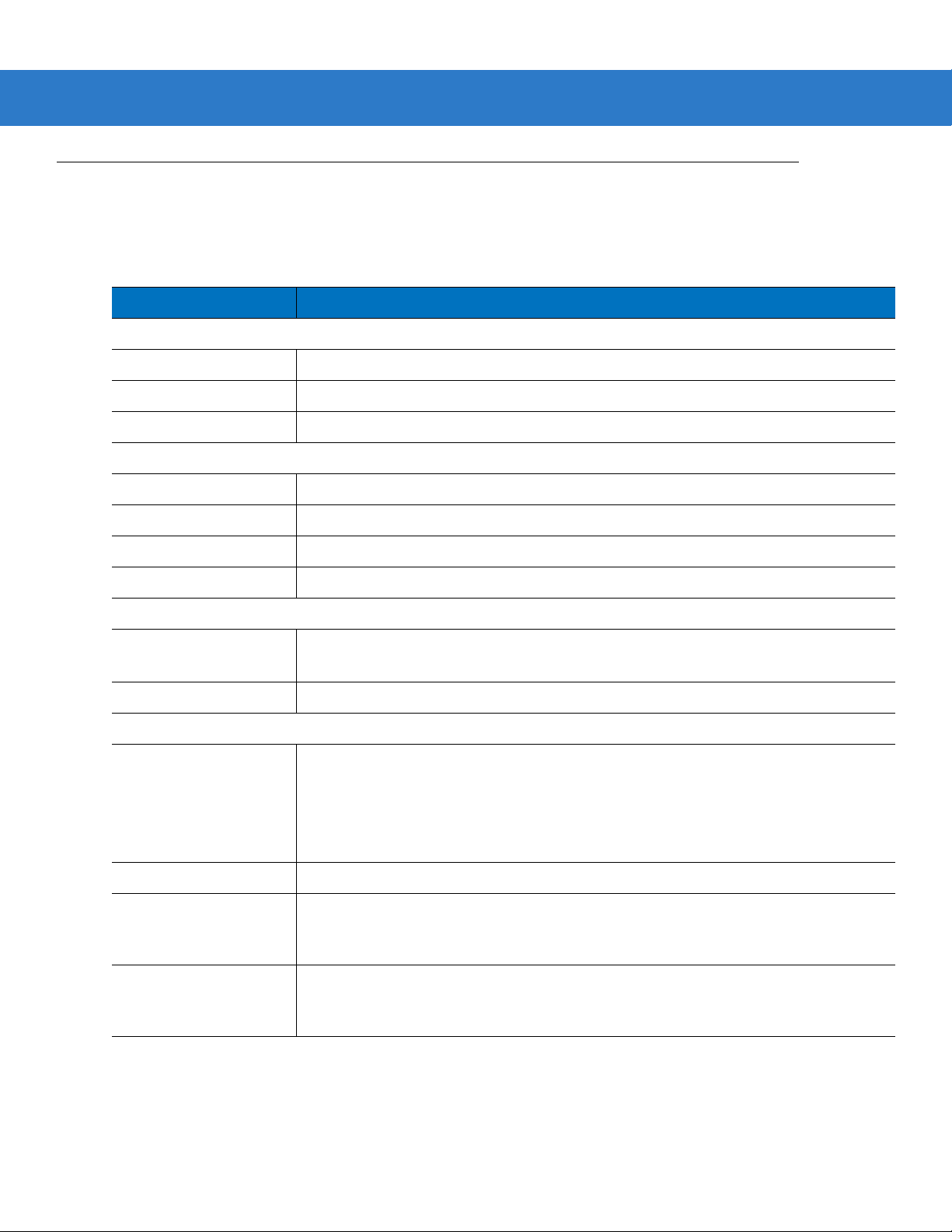
Revision History
Changes to the original manual are listed below:
Change Date Description
-01 Rev A 09/2009 Initial release.
-02 Rev A 11/2009 Updates to:
-03 Rev A 02/2010 Added UID.
-04 Rev A 04/2010 Removed reference to Synapse (not supported); removed Regulatory
iii
- Presentation Mode Field of View’ bar codes
- Supported baud rates for RS232.
Updated DPM information.
information as the complete Regulatory requirements appear in the Quick Start
Guide; updated IEC definition in Glossary.
Page 6

iv Symbol DS3508 Product Reference Guide
Page 7

Table of Contents
Warranty ........................................................................................................................ ii
Revision History............................................................................................................. iii
About This Guide
Introduction.................................................................................................................... xv
Configurations................................................................................................................ xv
Chapter Descriptions..................................................................................................... xvi
Notational Conventions............... .. ............................... .. ............................... ................. xvii
Related Documents ............ .. .. ............. ... .......................... .. .............. .. .. ............. ... ......... xvii
Service Information........................................................................................................ xviii
Chapter 1: Getting Started
Introduction ................................................................................................................... 1-1
Interfaces ...................................................................................................................... 1-2
Unpacking ..................................................................................................................... 1-2
Setting Up the Digital Scanner .................. .......................................................... .......... 1-3
Installing the In te rface Cable ...... .............. .. .. ............. .. ........................... .. ............. . 1- 3
Removing the Interface Cable ................................................................................ 1-4
Connecting Power (if required) ............... ..................................................... ........... 1-4
Configuring the Digital Scanner .............................................................................. 1-4
Accessories .................................................................................................................. 1-5
Required Accessories ............................................................................................. 1-5
Optional Accessories .............................................................................................. 1-5
Chapter 2: Scanning
Introduction ................................................................................................................... 2-1
Beeper Definitions ......... ..................................................... .......................................... 2-2
LED Definitions ............................................................................................................. 2-4
Scanning .... ................... .................. .................... .................... ................. .................... . 2-5
Presentation Mode ..................................... .. ........................................................... 2-5
Hand-Held Scanning ............................................................................................... 2-6
Page 8

vi Symbol DS3508 Product Reference Guide
DS3508-SR/HD/DP Hand-Held Scanning ....................... .. ............................... 2-6
Aiming .... ........................ ........................ ...................... ......................... .................. 2-6
Imager Aiming .................... ............................................................................... 2-6
Decode Ranges ............................................................................................................ 2-8
Chapter 3: Maintenance & Technical Specifications
Introduction ................................................................................................................... 3-1
Maintenance ................................................................................................................. 3-1
Troubleshooting ............................................................................................................ 3-2
Technical Specifications ............................................................................................... 3-5
Digital Scanner Signal Descriptions .............................................................................. 3-7
Chapter 4: User Preferences & Miscellaneous Digital Scanner Options
Introduction ................................................................................................................... 4-1
Scanning Sequence Examples ..................................................................................... 4-2
Errors While Scanning .................................................................................................. 4-2
User Preferences/Miscellaneous Options Parameter Defaults ................. .................... 4-2
User Preferences .......................................................................................................... 4-4
Set Default Parameter ............................................................................................ 4-4
Parameter B a r Co de S c a nn ing ............ ............. ... ............. .. .. ............. ... ............. .. ... 4-5
Decode Pager Motor Enable ................................................................................... 4-6
Decode Pager Motor Duration .......................................................................... 4-6
Beep After Good Decode ........................................................................................ 4-8
Beeper Volume ........................ .......................... ......................... .......................... .. 4-8
Beeper Tone .............................. .. ................................................................ ........... 4-9
Beeper Duration ............................. ......................................................................... 4-10
Hands-Free Mode ................................................................................................... 4-10
Presentation Performance Mode .......................... .. ..................................... ........... 4-11
Digital Scanner Activity Modes ............................................................................... 4-11
Active Mode ...................................................................................................... 4-11
Idle Mode .......................................................................................................... 4-11
Sleep Mode ....................................................................................................... 4-11
Low Power Mode .................................................................................... .......... 4-11
Time Delay to Presentation Idle Mode .............................................................. 4-12
Time Delay to Presentation Sleep Mode .................................................. ........ 4-14
Low Power Mode .................................................................................... .......... 4-16
Time Delay to Low Power Mode ....................................................................... 4-17
Trigger Mode .............................................. ............................................................. 4-19
Picklist Mode ................................................................................................... .. ...... 4-20
DPM Scanni ng .... ............. .. ........................... .. ............. ... ............. .. .. .............. .. ....... 4-21
Continuous Bar Code Read ...................................... .............................................. 4-22
Decode Session Timeout ........................................................................................ 4-22
Timeout Between Decodes, Same Symbol ............................................................ 4-23
Timeout Between Decodes, Different Symbols ...................................................... 4-23
Hand-Held Decode Aiming Pattern ......................................................................... 4-24
Hands-Free Decode Aiming Pattern ....................................................................... 4-25
Presentation Mode Field of View .................................................................. .......... 4-26
Decoding Illumination (Hand-Held Mode only) ......................... .............................. 4-27
Page 9

Miscellaneous Scanner Parameters ................................... .......................................... 4-28
Transmit Code ID Character ................................................................................... 4-28
Prefix/Suffix V a lu e s . ... .......................... .. .............. .. .. ............. .. ........................... .. ... 4-29
Scan Data Tran s m is s io n Fo r m a t ................ .. .......................... ... .......................... .. . 4-30
FN1 Substitution Values ......................................................................................... 4-31
Scan Data Tran s m is s io n Fo r m a t (c o n tinued) ........ .. .......................... ... ............. .. .. . 4-31
Transmit “No Read” Message ................................................................................. 4-32
UID Parsing .. ........................... .. ............. ... .. ............. .. ........................... .. ................ 4-33
UID Parsing Ou tp u t ......... .. .. ............. ... .......................... .. ............. ... .. ............. .. . 4- 3 4
UID Error Mode Options ................................................................................... 4-35
Sample ADF Rule for UID ................................................................................. 4-36
UID Sample Ba r C o d es ..... .. .. .............. .. ............. .. .. .............. .. .......................... . 4- 3 7
Chapter 5: Imaging Preferences
Introduction ................................................................................................................... 5-1
Scanning Sequence Examples ..................................................................................... 5-2
Errors While Scanning .................................................................................................. 5-2
Imaging Pref e re n c e s Pa ra meter Defaults ............... ... .......................... .. ....................... 5-2
Imaging Pref e re n c e s ........ ............. .. .. .............. .. ............. .. .. .............. .. .......................... . 5- 4
Operational Modes ................. ................................... ................................... ........... 5-4
Decode Mode .................................................................................................... 5-4
Snapshot Mode ............................................................ .. ................................... 5-4
Image Capture Illumination ..................................................................................... 5-5
Gain/Exposure Priority for Snapshot Mode ........ ..................................................... 5-6
Snapshot Mode Timeout ..................................... .. ..................................... ............. 5-7
Snapshot Aiming Pattern ................................................. ....................................... 5-7
Image Cropping ...................................................................................................... 5-8
Crop to Pixel Addresses ......................................................................................... 5-9
Image Size (Number of Pixels) ............................................................................... 5-10
Image Brightness (Target White) ............................................................................ 5-11
JPEG Image Options .......................... ........................... ......................................... 5-11
JPEG Target File Size ............................................................................................ 5-12
JPEG Quality and Size Value ................................................................................. 5-12
Image Enhancement ............................................................................................... 5-13
Image File Format Selector ..................................................................................... 5-14
Bits Per Pixel ........................... .. ............. ... .. ............. .. ........................... .. ................ 5-15
Signature Capture ............................. ............................... .. ............................... ...... 5-16
Output File Format ............................................................................................ 5-16
Signature Capture File Format Selector .. ............................................................... 5-17
Signature Capture Bits Per Pixel . .......................................................... ................. 5-18
Signature Capture Width .................................................. .. ..................................... 5-19
Signature Capture Height ....................................................................................... 5-19
Signature Capture JPEG Quality .................................................................. .......... 5-19
Video View Finder .............................................................. .. ............................... .. .. 5-20
Video View Finder Image Size ................................................................................ 5-20
Table of Contents vii
Page 10

viii Symbol DS3508 Product Reference Guide
Chapter 6: USB Interface
Introduction ................................................................................................................... 6-1
Connecting a USB Interface ......................................................................................... 6-2
USB Parameter Defaults ........... ................................................................................... 6-3
USB Host Parameters ................. .. ................................................................ ............... 6-4
USB Device Type ......................... .................................. ..................................... .... 6-4
Symbol Native API (SNAPI) Status Handshaking .............. ................................... .. 6-5
USB Country Keyboard Types - Country Codes .................. ................................... 6-6
USB Keystroke Delay ............................................................................................. 6-8
USB CAPS Lock Override .............. ..................................... ................................... 6-8
USB Ignore Unknown Characters ........................................................................... 6-9
Emulate Keypad ..................... ......................................................................... ........ 6-9
Emulate Keypad with Leading Zero .............................. .......................................... 6-10
USB Keyboard FN 1 Substitution ............... .. ................................. .......................... 6-10
Function Key Mapping .......................... ............................. ............................. ........ 6-11
Simulated Caps Lock .............................................................................................. 6-11
Convert Cas e .... .. .......................... ... .......................... .. .............. .. .. ............. ... ......... 6-12
ASCII Character Set for USB ........................................................................................ 6-13
Chapter 7: RS-232 Interface
Introduction ................................................................................................................... 7-1
Connecting an RS-232 Interface ............ ...................................................................... 7-2
RS-232 Parameter Defaults ................. ...................................................... ................... 7-3
RS-232 Host Parameters ..................... ..................................................... .................... 7-4
RS-232 Host Types ................................................................................................. 7-6
Baud Rate ......................................... .. .. .................................................................. 7-7
Parity ...... ............. ........... ............. .............. ........... ............. ............. ........... ............. . 7-9
Data Bits ......... .. .......................... .. ........................... .. ............. ... .. ............. .. ............ 7-9
Check Recei ve E rrors ........... ............. .. ........................... .. ............. .. .. .............. .. ..... 7-10
Hardware Handshaking .... ........................... ......................................................... .. 7-10
Software Ha nd s h a k in g ............ .. ............. ... .. ............. .. ............. ... ............. .. .. ............ 7-12
Host Serial Re s p o nse T i me -out ........... ............. ... .. ............. .. .. .............. .. ................ 7-14
RTS Line Stat e .. ............. .. ............. ... .. ............. .. .............. .. .......................... ... ......... 7-15
Beep on <BEL> ................... ........................... ........................... ............................ .. 7-15
Intercharacter Delay ................................................................................................ 7-16
Nixdorf Beep/LED Options ................................. ..................................................... 7-17
Ignore Unknown Characters ................................................................................... 7-17
ASCII Character Set for RS-232 ................................................................................... 7-18
Chapter 8: IBM 468X / 469X Interface
Introduction ................................................................................................................... 8-1
Connecting to an IBM 468X/469X Host ........................................................................ 8-2
IBM Parameter Defaults ............................................................................................... 8-3
IBM 468X/469X Host Parameters .................................................................... ............. 8-4
Port Address ........................................................................................................... 8-4
Convert Unk now n to C o d e 39 . .. ............. ... .. ............. .. ........................... .. ................ 8-5
Page 11

Chapter 9: Keyboard Wedge Interface
Introduction ................................................................................................................... 9-1
Connecting a Keyboard Wedge Interface ................. .. ................................. .. ............... 9-2
Keyboard Wedge Parameter Defaults ................................ ............................... ........... 9-3
Keyboard Wedge Host Parameters .............................................................................. 9-4
Keyboard Wedge Host Types .......................... ....................................................... 9-4
Keyboard Wedge Country Types - Country Codes ............................................... .. 9-5
Ignore Unknown Characters ................................................................................... 9-7
Keystroke Delay ...................................................................................................... 9-7
Intra-Keystroke Delay ............................................................................................. 9-8
Alternate Nu m e ri c K e y p ad E m u la tion ........... ............. .. ........................... .. ............. . 9- 8
Caps Lock On ........................... .. .. .............. .. .. ............. ... ............. .. .. .............. .. .. ..... 9-9
Caps Lock Ove rride ......................... ............. .. ........................... .. .......................... . 9- 9
Convert Wedge Data .......... ........................... ........................... .............................. 9-10
Function Key Mapping .......................... ............................. ............................. ........ 9-10
FN1 Substitution ..................................................................................................... 9-11
Send Make and Break ............. ............................. .................................................. 9-11
Keyboard Maps ....................................................................................................... 9-12
ASCII Character Set for Keyboard Wedge ................................................................... 9-13
Table of Contents ix
Chapter 10: Symbologies
Introduction ................................................................................................................... 10-1
Scanning Sequence Examples ..................................................................................... 10-1
Errors While Scanning .................................................................................................. 10-2
Symbology Parameter Defaults .................................................................................... 10-2
UPC/EAN ...................................................................................................................... 10-7
Enable/Disable UPC-A ............................................................................................ 10-7
Enable/Disable UPC-E ............................................................................................ 10-7
Enable/Disable UPC-E1 .......................................................................................... 10-8
Enable/Disable EAN-8/JAN-8 ................................................................................. 10-8
Enable/Disable EAN-13/JAN-13 ............................................................................. 10-9
Enable/Disable Bookland EAN ................................... ............................... ............. 10-9
Decode UPC/EAN/JAN Supplementals .................................................................. 10-10
User-Programmable Supplementals .................................. ..................................... 10-13
UPC/EAN/JAN Supplemental Redundancy ............................................................ 10-13
UPC/EAN/JAN Supplemental AIM ID Format .................. .. ..................................... 10-14
Transmit UPC-A Check Digit .................................................................................. 10-14
Transmit UPC-E Check Digit .................................................................................. 10-15
Transmit UPC-E1 Check Digit ................................................................................ 10-15
UPC-A Preamble .............. .................................... .................................................. 10-16
UPC-E Preamble .............. .................................... .................................................. 10-17
UPC-E1 Preamble .............................................. .. .................................................. 10-18
Convert UPC-E to UPC-A ....................................................................................... 10-19
Convert UPC-E1 to UPC-A ..................................................................................... 10-19
EAN-8/JAN-8 Extend .............................................................................................. 10-20
Bookland ISBN Format ........................................................................................... 10-21
UCC Coupon Extended Code ................................................................................. 10-22
ISSN EAN ............................................................................................................... 10-22
Code 128 .... .. .. .. ........................................ .. .. ........................................ .. .. .................... 10-23
Page 12

x Symbol DS3508 Product Reference Guide
Enable/Disable Code 128 ............................ .. ..................................... .................... 10-23
Set Lengths for Code 128 ................................................................. ...................... 10-23
Enable/Disable GS1-128 (formerly UCC/EAN-128) ................................................ 10-24
Enable/Disable ISBT 128 ........................................................................................ 10-25
ISBT Concatenation ................................................................................................ 10-26
Check ISBT Ta bl e .............. ... ............. .. .. .............. .. .......................... .. ..................... 10-27
ISBT Concatenation Redundancy ........................................................................... 10-27
Code 39 .... .. .. .. ........................................ .. .. ........................................ .. .. .. .................... 10-28
Enable/Disable Code 39 ............................................................. .. .......................... 10-28
Enable/Disable Trioptic Code 39 ............................................................................ 10-28
Convert Code 39 to Code 32 ........................................................................ .. ........ 10-29
Code 32 Prefix ............................. ............................... .. ............................... ........... 10-29
Set Lengths for Code 39 ................................................................. ........................ 10-30
Code 39 Check Digit Verification .......................... ................................... ............... 10-31
Transmit Code 39 Check Digit ................................................................................ 10-31
Code 39 Full ASCII Conversion .................................... .......................................... 10-32
Code 39 Buffering - Scan & Store .................. ......................................................... 10-32
Buffer Data ........... ............. .. .. .............. .. .......................... .. .............. .. .. ............. . 10 - 3 3
Clear Transmission Buffer ................................................................................ 10-33
Transmit Buffer ................................................................................................. 10-34
Overfilling Transmission Buffer ......................................................................... 10-34
Attempt to Transmit an Empty Buffer ................................................................ 10-34
Code 93 .... .. .. .. ........................................ .. .. ........................................ .. .. .. .................... 10-35
Enable/Disable Code 93 ............................................................. .. .......................... 10-35
Set Lengths for Code 93 ................................................................. ........................ 10-35
Code 11 .... .. .. .. ........................................ .. .. ........................................ .. .. .. .................... 10-37
Code 11 ........... ....................................................................................................... 10-37
Set Lengths for Code 11 ................................................................. ........................ 10-37
Code 11 Check Digit Verification .......................... ................................... ............... 10-39
Transmit Code 11 Check Digits .............................................................................. 10-40
Interleaved 2 of 5 (ITF) ................................................................................................. 10-40
Enable/Disable Interleaved 2 of 5 ....................... ................................. ................... 10-40
Set Lengths for Interleaved 2 o f 5 ............... .. .......................... ... ............. .. .............. 10-41
I 2 of 5 Check Digit Verification ............................................................................... 10-43
Transmit I 2 of 5 Check Digit ................................................................................... 10-43
Convert I 2 of 5 to EAN-13 .................. ................................................................ .... 10-44
Discrete 2 of 5 (DTF) .................................................................................................... 10-44
Enable/Disable Discrete 2 of 5 ........................................... ................................. .... 10-44
Set Lengths for Discrete 2 of 5 ..... .............. .. ............. .. .............. .. .. ............. ... ......... 10-4 5
Codabar (NW - 7) ......................................................................................................... 10-47
Enable/Disable Codabar ......................................................................................... 10-47
Set Lengths for Codabar ......................................................................................... 10-47
CLSI Editing ...... .......................... .. ........................... .. ............. ... .. ............. .. ............ 10- 4 9
NOTIS Editing ......................................................................................................... 10-49
MSI ............................................................................................................................... 10-50
Enable/Disable MSI ................................................................................................ 10-50
Set Lengths for MSI ......................... .. ............. .. ... ............. .. ........................... .. ....... 10-50
MSI Check Digits .................................................................................................... 10-52
Transmit MSI Check Digit(s) ................................................................................... 10-52
MSI Check Digit Algorithm ............... .. .. ............. ... ............. .. ........................... .. ....... 10-53
Page 13

Table of Contents xi
Chinese 2 of 5 ............................................................................................................... 10-53
Enable/Disable Chinese 2 of 5 ................................................................................ 10-53
Matrix 2 of 5 . ............. .. ........................... .. ............. .. ... ............. .. ........................... .. ....... 10-54
Enable/Disable Matrix 2 of 5 ................................................................................... 10-54
Set Lengths for Matrix 2 of 5 ................................................................................... 10-55
Matrix 2 of 5 Redundancy .......................................................................... ............. 10-56
Matrix 2 of 5 Chec k D ig it ........... .. ........................... .. ............. .. ... ............. .. .............. 10-56
Transmit Matrix 2 of 5 Check Digit .......................................................................... 10-57
Inverse 1D .................................................................................................................... 10-57
Postal Codes ........................... ... .. ............. .. .............. .. .. ............. .. ........................... .. ... 10-58
US Postnet .............................................................................................................. 10-58
US Planet ............................. ............................ ........................... ............................ 10-58
Transmit US Po s ta l C h e ck D ig it ......... .. .. .............. .. ............. .. .. .............. .. ................ 10-59
UK Postal ................................................................................................................ 10-59
Transmit UK Po s ta l C h e ck D ig it ......... .. .. .............. .. ............. .. .. .............. .. ................ 10-60
Japan Postal ........................................................................................................... 10-60
Australian Postal ..................................................................................................... 10-61
Netherlands KIX Code ........................................................................................... 10-61
USPS 4CB/One Code/Intelligent Mail ..................................................................... 10-62
UPU FICS Postal .................................................................................................... 10-62
GS1 DataBar ................................................................................................................ 10-63
GS1 DataBar-14 ..................................................................................................... 10-63
GS1 DataBar Limited .............................................................................................. 10-63
GS1 DataBar Expanded .............. .. ...................................... ................................... 10-64
Convert GS1 DataBar to UPC/EAN ........................................................................ 10-64
Composite .. ........ ......... ....... ......... ........ ......... ....... ......... ......... ...... ......... ......... ....... ........ . 10-65
Composite CC -C ......................... .. .............. .. .. ............. ... .......................... .. ............ 10- 6 5
Composite CC -A/B ....... .. .. ............. ... ............. .. .. .............. .. .......................... ... ......... 10-6 5
Composite TL C -3 9 ............. ... .......................... .. .............. .. .. ............. .. ..................... 10-66
UPC Composite Mode ............................................................................................ 10-66
Composite Beep Mode .................. .......................................... ............................... 10-67
GS1-128 Emulation Mode for UCC/EAN Composite Codes ...................... .. ........... 10-67
2D Symbologies ............................................................................................................ 10-68
Enable/Disable PDF417 .......................................................................................... 10-68
Enable/Disable MicroPDF417 ................................................................................. 10-68
Code 128 Emulation .............. .. ...................................... .. .. ..................................... 10-69
Data Matrix . ........................... .. ............. .. ... ............. .. .......................... ... .................. 10-70
Data Matrix Inverse ................................................................................................. 10-70
Maxicode ................................................................................................................. 10-71
QR Code ................................. .. ............. ... ............. .. .. ............. ... ............. .. .............. 10-71
QR Inverse ... ........................... .. ........................... .. ............. .. .. .............. .. .. ............. . 10 - 7 2
MicroQR ... ............... .............. ............... ................ ............. ............... ................ ....... 10- 72
Aztec ...... ........................ ........................ ...................... ......................... .................. 10-73
Aztec Inverse .......................................................................................................... 10-73
Redundancy Level ..................... ........................................................................ ........... 10-74
Redundancy Level 1 ................................ ............................................................... 10-74
Redundancy Level 2 ................................ ............................................................... 10-74
Redundancy Level 3 ................................ ............................................................... 10-74
Redundancy Level 4 ................................ ............................................................... 10-75
Security Lev el ...................... .. ............. ... ............. .. ........................... .. ............. .. ............ 10-76
Page 14

xii Symbol DS3508 Product Reference Guide
Intercharacter Gap Size .......................................................................................... 10-77
Report Version .............................................................................................................. 10-77
Macro PDF Features ....................... .................................... .. ..................................... .. 10-78
Flush Macro Buffer .................................................................................................. 10-78
Abort Macro PDF Entry ........................................................................................... 10-78
Chapter 11: 123Scan
Introduction ................................................................................................................... 11-1
Communication with 123Scan2 ...................................... .. .................................. .. ........ 11-1
123Scan2 Requirements .............................................................................................. 11-2
More Information ... ............. .. .. ............. ... ............. .. .. .............. .. .......................... ... ......... 11-2
Chapter 12: Advanced Data Formatting
Introduction ................................................................................................................... 12-1
Appendix A: Standard Default Parameters
Appendix B: Programming Reference
Symbol Code Identifiers ................................................................................. ............... B-1
AIM Code Identifiers ........................ ........................... .................................................. B-3
Appendix C: Sample Bar Codes
Code 39 .... .. .. .. ........................................ .. .. ........................................ .. .. .. .................... C-1
UPC/EAN ...................................................................................................................... C-1
UPC-A, 100% .......................................................................................................... C-1
EAN-13, 100% ........................................................................................................ C-2
Code 128 .... .. .. .. ........................................ .. .. ........................................ .. .. .................... C-2
Interleaved 2 of 5 .......................................................................................................... C-2
GS1 DataBar-14 ........................................................................................................... C-3
PDF417 ......................................................................................................................... C-3
Data Matrix .. ............. .. ........................... .. .......................... ... ............. .. .. .............. .. ....... C-3
Maxicode ...................................................................................................................... C-4
QR Code ............ ... .. ............. .. ............. ... ............. .. .. .............. .. ............. .. ....................... C-4
US Postnet .................................................................................................................... C-4
UK Postal ...................................................................................................................... C-4
Appendix D: Numeric Bar Codes
Numeric Bar Codes ........................... .. ...................................... .. .. ............................... D-1
Cancel ... ....... ...... ....... .... ....... ....... .... ....... ...... ..... ...... ....... ....... .... ....... ...... ..... ...... ....... ..... D-2
Page 15

Appendix E: ASCII Character Sets
Appendix F: Signature Capture Code
Introduction ................................................................................................................... F-1
Code Structure .................. ............................ ...................................................... .......... F-1
Signature Capture Area ...................... ............................................................ ........ F-1
CapCode Pattern Structure ..................... ................................................................ F-2
Start / Stop Patterns ..................................................................................................... F-2
Dimensions ................................................................................................................... F-3
Data Format .......... .......................... .. ........................... .. ............. .. ... ............. .. .............. F-3
Additional Capabilities ...... .. ............................. ............................................................. F-4
Signature Boxes ................. ................................... .. ..................................................... F-4
Index
Glossary
Table of Contents xiii
Tell Us What You Think...
Page 16

xiv Symbol DS3508 Product Reference Guide
Page 17

About This Guide
Introduction
The Symbol DS3508 Product Reference Guide provides general instructions for setting up, operating, maintaining,
and troubleshooting the Symbol DS3508 digital scanner.
Configurations
This guide includes the following configurations:
•
DS3508-SR20005R – DS3508 digital scanner, standard range
•
DS3508-HD20005R – DS3508 digital scanner, high density focus
•
DS3508-DP20005R – DS3508 digital scanner, DPM.
Page 18

xvi Symbol DS3508 Product Reference Guide
Chapter Descriptions
Topics covered in this guide are as follows:
•
Chapter 1, Getting Started provides a product overview, unpacking instructions, and cable connection
information.
•
Chapter 2, Scanning describes parts of the digital scanner, beeper and LED definitions, and how to use the
scanner in hand-held and hands-free (presentation) modes.
•
Chapter 3, Maintenance & Technical Specifications provides information on how to care for the digital
scanner, troubleshooting, and technical speci fic at ion s.
•
Chapter 4, User Preferences & Miscellaneous Digital Scanner Options describes features frequently used to
customize how data transmits to the host device and programming bar codes for selecting user preference
features for the digital scanner.
•
Chapter 5, Imaging Preferences provides imaging preference features and programming bar codes for
selecting these feature s.
•
Chapter 6, USB Interface describes how to set up the digital scanner with a USB host.
•
Chapter 7, RS-232 Interface describes how to set up the digital scanner with an RS-232 host, such as
point-of-sale devices, host computers, or other devices with an available RS-232 port.
•
Chapter 8, IBM 468X / 469X Interface describes how to set up the digital scanner with IBM 468X/469X POS
systems.
•
Chapter 9, Keyboard Wedge Interface describes how to set up a Keyboard Wedge interface with the digital
scanner.
•
Chapter 10, Symbologies describes all symbology features and provides programming bar codes for
selecting these features for the digital scanner.
•
Chapter 12, Advanced Data Formatting briefly describes ADF, a means of customizing data befo re
transmission to the host device, and includes a reference to the ADF Programmer Guide.
•
Appendix A, Standard Default Parameters provides a table of all host devices and miscellaneous scanner
defaults.
•
Appendix B, Programming Reference provides a table of AIM code identifiers, ASCII character conversions,
and keyboard maps.
•
Appendix C, Sample Bar Codes includes sample bar codes of various code types.
•
Appendix D, Numeric Bar Codes includes the numeric bar codes to scan for parameters requiring specific
numeric values.
•
Appendix E, ASCII Character Sets provides ASCII character value tables.
•
Appendix F, Signature Capture Code provides information on CapCode, a signature capture code that
encloses a signature area on a document and allows a scanner to capture a signature.
Page 19

Notational Conventions
*Baud Rate 9600
Feature/Option
* Indicates Default
The following conventions are used in this document:
•
Italics are used to highlight the following:
• Chapters and sections in this and related documents
• Dialog box, window and screen names
• Drop-down list and list box names
• Check box and radio button names
•
Bold text is used to highlight the following:
• Key names on a keypad
• Button names on a screen.
•
bullets (•) indicate:
• Action items
• Lists of alternatives
• Lists of required steps that are not necessarily sequential
About This Guide xvii
•
Sequential lists (e.g., those that describe step-by-step procedures) appear as numbered lists.
•
Throughout the programming bar code menus, asterisks (*) are used to denote default parameter settings.
Related Documents
•
Symbol DS3508 Quick Start Guide, p/n 72-124802-xx - provides general information for getting started with
the Symbol DS3508 digital scanner, and includes basic set up and operation instructions.
For the latest version of all guides, go to: http://www.motorola.com/enterprisemobility/manuals
.
Page 20

xviii Symbol DS3508 Product Reference Guide
Service Information
If you have a problem with your equipment, contact Motorola Enterprise Mobility support for your region. Contact
information is available at:
When contacting Enterprise Mobility support, please have the following information available:
•
Serial number of the unit
•
Model number or product name
•
Software type and version number
Motorola responds to calls by e-mail, telephone or fax within the time limits set forth in service agreements.
If your problem cannot be solved by Motorola Enterprise Mobility Support, you may need to return your equipment
for servicing and will be given specific directions. Motorola is not responsible for any damages incurred during
shipment if the approved shipping container is not used. Shipping the units improperly can possibly void the
warranty.
If you purchased your Enterprise Mobility business product from a Motorola business partner, please contact that
business partner for support.
http://www.motorola.com/enterprisemobilitysupport.
Page 21
Chapter 1 Getting Started
Introduction
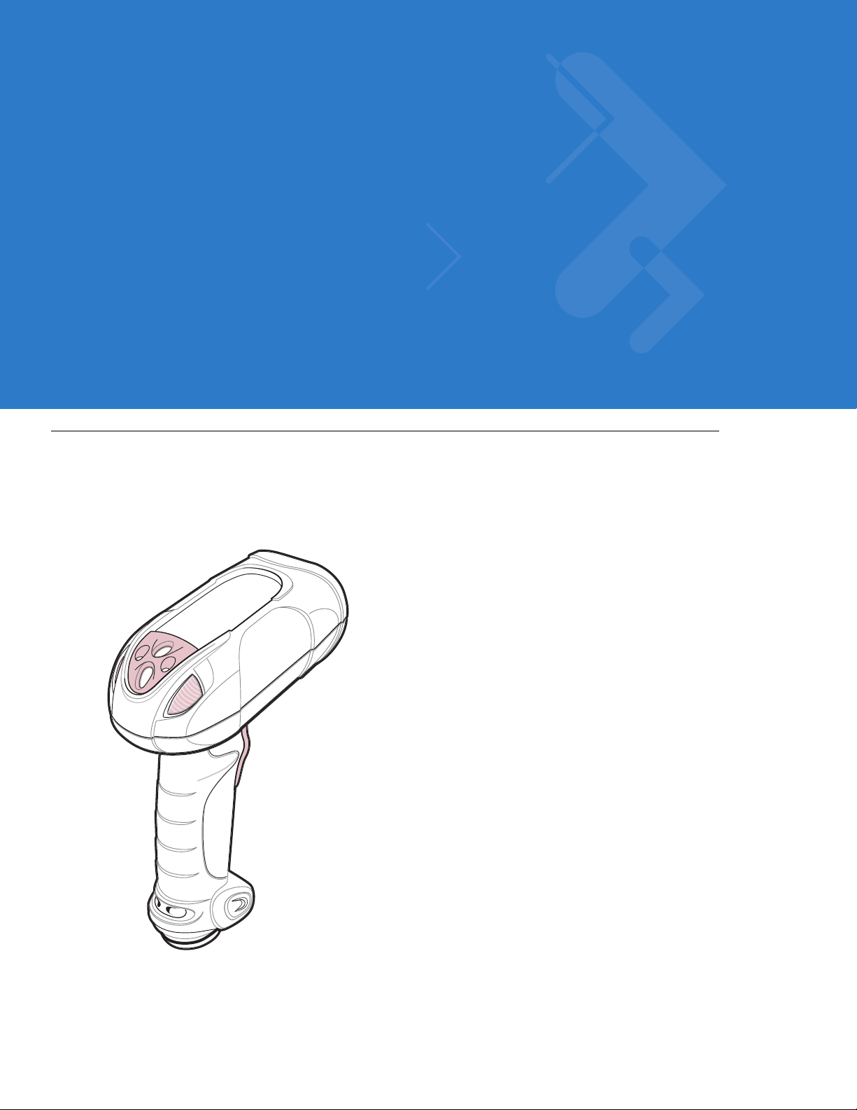
The Symbol DS3508 combines superior 1D and 2D omnidirectional bar code scanning and sub-second image
capture and transfer with a light-weight, hands-free/hand-held design. The digital scanner accommodates both
hands-free use (in the scan stand) and hand-held use. Whether in hands-free (presentation) or hand-held mode,
the digital scanner ensures comfort and ease of use for extended periods of time.
Figure 1-1
Symbol DS3508 Digital Scanner
Page 22

1 - 2 Symbol DS3508 Product Reference Guide
Interfaces
The DS3508 digital scanner supports:
•
USB connection to a host. The digital scanner autodetects a USB host and defaults to the HID keyboard
interface type. Select other USB interface types by scanning programming bar code menus.This interface
supports the following international keyboards (for Windows® environment): North America, German,
French, French Canadian, Spanish, Italian, Swedish, UK English, Portuguese-Brazilian, and Japanese.
•
Standard RS-232 connection to a host. Scan bar code menus to set up communication of the digital scanner
with the host.
•
Connection to IBM 468X/469X hosts. Scan bar code menus to set up communication of the digital scanner
with the IBM terminal.
•
Keyboard Wedge connection to a host. The host interprets scanned data as keystrokes. Scan bar code
menus to set up communication of the digital scanner with the host. This interface supports the following
international keyboards (for Windows® environment): North America, German, French, French Canadian,
French Belgian, Spanish, Italian, Swedish, UK English, Portuguese-Brazilian, and Japanese.
Unpacking
Remove the digital scanner from its packing and inspect it for damage. If the scanner was damaged in transit,
contact Motorola Enterprise Mobility Support. See page xviii for contact informa tion. KEEP THE PACKING . It is the
approved shipping container; use this to return the equipment for servicing.
Page 23
Setting Up the Digital Scanner
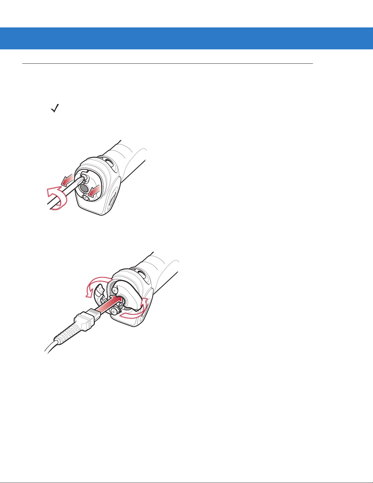
Installing the Interface Cable
NOTE Different host s require dif fere nt cable s. The c onnec tors illust rate d in each host cha pter are ex amples only.
Connectors vary from those illustrated, but the steps to connect the digital scanner are the same.
1. Loosen the two screws on the cable clamp at the bottom of the scanner and gently pull the clamp away from
the bottom of the scanner.
Getting Started 1 - 3
Figure 1-2
2. Open the clamp and plug the interface cable modular connector into the cable interface port on the bottom of
the scanner handle.
Figure 1-3
3. Gently tug the cable to ensure the connector is properly secured.
Removing the Cable Clamp
Inserting the Interface Cable
Page 24
1 - 4 Symbol DS3508 Product Reference Guide
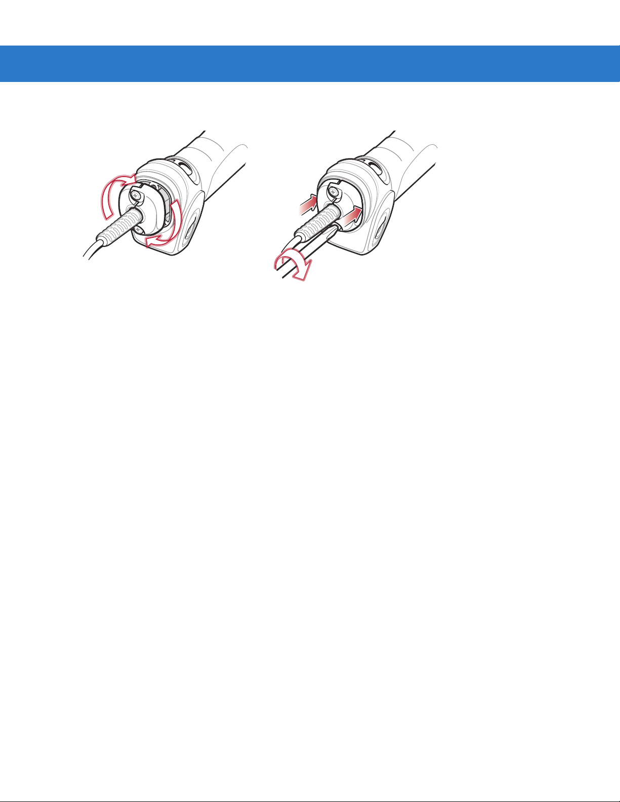
4. Close the clamp, push it back into place and tighten the screws on the clamp to secure the cable into the
bottom of the scanner.
Figure 1-4
5. Connect the other end of the interface cable to the host (see the specific host chapter for information on host
connections).
Closing the Cable Clamp
Removing the Interface Cable
1. Loosen the two screws on the cable clamp at the bottom of the scanner and gently pull the clamp away from
the bottom of the scanner.
2. Open the clamp and unplug the interface cable modular connector from the cable interface port on the bottom
of the scanner handle. Carefully slide out the cable.
3. Follow the steps for Installing the Interface Cable on page 1-3 to connect a new cable.
Connecting Power (if required)
If the host does not provide power to the digital scanner, connect an external power supply:
1. Connect the interface cable to the base of the digital scanner, as described in Installing the Interface Cable on
page 1-3.
2. Connect the other end of the interface cable to the host (refer to the host manual to locate the correct port).
3. Plug the power supply into the power jack on the interface cable. Plug the other end of the power supply into
an AC outlet.
Configuring the Digital Scanner
To configure the digital scanner use the bar codes included in this manual. See Chap ter 4, User Pr efe renc es &
Miscellaneous Digital Scanner Options and Chapter 5, Imaging Preferences for information about programming the
digital scanner using bar code menus. Also see each host-specific chapter to set up connection to a specific host
type.
Page 25

Accessories
Required Accessories
The digital scanner requires an interface cable and may require a power supply. These items can be purchased
from Motorola.
Optional Accessories
Contact Motorola to purchase the optional accessories inTable 1-1 for the DS3508.
Getting Started 1 - 5
Table 1-1
Scanner Belt Holster 11-35035-01R
Intellistand for DS3508 20-54090-07R (see page 2-5).
Desk Top Holder 20-67176-01R
Multi-Mount Stand 12-44267-01R
Tool Balancer 50-15400-03
Optional Accessories
Accessory Part Number
Page 26

1 - 6 Symbol DS3508 Product Reference Guide
Page 27

Chapter 2 Scanning
Scan Trigger
Scan Window
LED
Indicators
Tether Plate
Introduction
This chapter provides beeper and LED definitions, techniques involved in scanning bar codes, general instructions
and tips about scanning, and decode zone diagrams.
Figure 2-1
Parts
Page 28

2 - 2 Symbol DS3508 Product Reference Guide
Beeper Definitions
The digital scanner issues different beep sequences and patterns to indicate status. Table 2-1 defines beep
sequences that occur during both normal scanning and while programming the digital scanner.
Table 2-1
Standard Use
Low/medium/high beeps Power up.
Short high beep A bar code symbol was decoded (if decode beeper is enabled).
4 long low beeps Transmission error.
5 low beeps Conversion or format error.
Low/low/low/extra low beeps RS-232 receive error.
High beep The digital scanner detected a <BEL> character over RS-232.
Image Capture
Low beep Snapshot mode started or completed.
High/low beeps Snapshot mode timed out.
Parameter Menu Scanning
Low/high beeps I nput error; incorrect bar code, programming sequence, or
High/low beeps Keyboard parameter selected. Enter value using numeric bar codes.
Beeper Definitions
Beeper Sequence Indication
Cancel
scanned.
High/low/high/low beeps Successful program exit with change in parameter setting.
Code 39 Buffering
High/low beeps New Code 39 data was entered into the buffer.
3 long high beeps Code 39 buffer is full.
High/low/high beeps The Code 39 buffer was erased.
Low/high/low beeps The Code 39 buffer was erased or there was an attempt to clear or transmit an
empty buffer.
Low/high beeps A successful transmission of buffered data.
Macro PDF
2 low beeps
2 long low beeps
3 long low beeps Out of memory . There is not enough buffer sp ac e to store the current MPDF
MPDF sequence buffered.
File ID error. A bar code not in the current MPDF sequence was scanned.
symbol.
Page 29

Scanning 2 - 3
Table 2-1
4 long low beeps Bad symbology. Scanned a 1D or 2D bar code in a MPDF sequence, a duplicate
5 long low beeps Flushing MPDF buffer .
Fast warble beep Aborting MPDF sequence.
Low/high beeps Flushing an already empty MPDF buffer.
Host Specific
USB only
4 short high beeps The digital scanner has not completed initialization. Wait several seconds and
Low/medium/high beeps
upon scanning a USB device
type
Low/medium/high beeps
occur more than once
Beeper Definitions (Conti nue d)
Beeper Sequence Indication
MPDF label, a label in an incorrect order, or trying to transmit an empty or illegal
MPDF field.
scan again.
Communication with the host must be established before the digital scanner can
operate at the highest power level.
The USB host can put the digital scanner in a state where power to the scanner is
cycled on and off more than once. This is normal and usually happens when the
PC cold boots.
RS-232 only
1 short high beep A <BEL> character is received and Beep on <BEL> is enabled.
Page 30
2 - 4 Symbol DS3508 Product Reference Guide
LED Definitions
In addition to beep sequences, the digital scanner uses a two-color LED to indicate status. Table 2-2 defines LED
colors that display during scanning.
Table 2-2
Hand-Held Scanning Standard Use
Green A bar code was successfully decoded.
Red Transmission error, conversion or format error, or RS-232 receive error.
Off No power is applied to the digital scanner, or the scanner is on and ready to scan.
Presentation (Hands-Free) Scanning Standard Use
Green The scanner is on and ready to scan.
Momentarily Off A bar code was successfully decoded.
Red Transmission error, conversion or format error, or RS-232 receive error.
Off No power is applied to the digital scanner, or the scanner is in low power mode.
Parameter Programming
Green Number expected. Enter value using numeric bar codes.
Red Input error: incorrect bar code, programming sequence, or Cancel scanned.
Standard LED Definitions
LED Indication
Successful program exit with change in parameter setting.
ADF Programming
Green Enter another digit. Add leading zeros to the front if necessary.
Enter another alphabetic character or scan the
All criteria or actions cleared for current rule, continue entering rule.
Delete last saved rule. The current rule is left intact.
All rules deleted.
Blinking Green Enter another criterion or action, or scan the
Green after Blinking Rule saved. Rule entry mode exited.
Cancel rule entry . Rule entry mode exited because of an error or the user asked to exit
rule entry.
Red Out of rule memory. Erase some existing rules, then try to save rule again.
Entry error, wrong bar code scanned, or criteria/action list is too long for a rule. Re-enter
criterion or action.
End of Message
Save Rule
bar code.
bar code.
Page 31

Scanning
Scanner “Cup”
Adjust height of
IntelliStand
Adjust angle of
scanner “cup”
Scanning 2 - 5
The Symbol DS3508 has a built-in, light-weight stand to easily accommodate both
hands-free (presentation)
hand-held scanning.
NOTE Certain areas of the digital scanner’s handle may feel warm at times. This is normal.
Presentation Mode
The optional Intellistand adds greater flexibility to scanning operation. When you place the digital scanner in the
stand’s “cup,” the scanner’s built-in sensor places the scanner in presentation (hands-free) mode. When you
remove the digital scanner from the stand it operates in its normal hand-held mode.
and
Figure 2-2
Scanning in Hands-Free Mode
To operate the digital scanner in the Intellistand:
1. Connect the digital scanner to the host (see the appropriate host chapter for information on host connections).
2. Insert the digital scanner in the Intellistand by placing the front of the digital scanner into the stand’s “cup” (see
Figure 2-2).
3. Use the Intellistand’s adjustment knobs to adjust the height and angle of the digital scanner.
4. Center the symbol in the aiming pattern.
5. Upon successful decode, the digital scanner beeps and the LED turns green. For more information on beeper
and LED definitions, see Table 2-1 on page 2-2 and Table 2-2 on page 2-4.
Page 32

2 - 6 Symbol DS3508 Product Reference Guide
Hand-Held Scanning
DS3508-SR/HD/DP Hand-Held Scanning
Aim the digital scanner at a bar code and pull the trigger to decode.
Figure 2-3
Scanning in Hand-Held Mode - DS3508-SR/HD/DP
Aiming
Imager Aiming
When scanning, the digital scanner projects a red laser aiming pattern which allows positioning the bar code within
its field of view. See Decode Ranges on page 2-8 for the proper distance to achieve between the digital scanner
and a bar code.
Figure 2-4
Imager Aiming Pattern
Page 33

Scanning 2 - 7
1D bar code symbol 2D bar code symbol 2D dot pe en DPM symbol
Aiming Pattern
0123 45
0123 45
0123 45
0123 45
If necessary, the digital scanner turns on its red LEDs to illuminate the target bar code.To scan a bar code, center
the symbol in any orientation within the aiming pattern. Be sure the entire symbol is within the rectangular area
formed by the cross pattern.
Figure 2-5
Scanning Orientation with Imager Aiming Pattern
NOTE Scanning Direct Part Mark (DPM) bar codes with the DS3508-DP20005R digital scanner: Due to the
reflective nature of some surfaces used with DPM bar codes (see Figure 2-5), it may be necessary to tilt
the scanner at an angle relative to the target (Motorola recommends 25-45 degrees). For example, when
scanning a 15 mil dot peen Datamatrix bar code marked on an aluminum surface with the
DS3508-DP20005R, present the target between two and three inches from the nose of the scanner, and
tilt the scanner at a 30 degree angle.
When scanning standard (non-DPM) bar codes with any configuration of the DS3508 digital scanner,
follow the standard aiming instructions described in Aiming on page 2-6.
The digital scanner can also read a bar code presented within the aiming pattern but not centered. The top
examples in Figure 2-6 show acceptable aiming options, while the bottom examples can not be decoded.
Figure 2-6
Acceptable and Incorrect Aiming
Page 34

2 - 8 Symbol DS3508 Product Reference Guide
Decode Ranges
Table 2-3
Code 39 - 3 mil
Code 39 - 4 mil
Code 39 - 5 mil
Code 39 - 7.5 mil
Code 39 - 20 mil
100% UPC - 13 mil
PDF417 - 6.67 mil
PDF417 - 10 mil
DS3508-SR/HD/DS3508-DP Depth of Field
Symbol Density DS3508-SR DS3508-HD/DS3508-DP
N/A 1.10 in. - 1.60 in.
2.79 cm - 4.06 cm
2.60 in. - 4.50 in.
6.60 cm - 11.43 cm
1.00 in. - 6.30 in.
2.54 cm - 16.00 cm
Contact - 10.10 in.
Contact - 25.65 cm
1.00 in. - 20.90 in.
2.54 cm - 53.09 cm
0.90 in. - 15.10 in.
2.29 cm - 38.35 cm
2.70 in. - 6.10 in.
6.86 cm - 15.49 cm
0.40 in. - 9.30 in.
1.02 cm - 23.62 cm
Contact - 3.5 in.
Contact - 8.89 cm
Contact - 4.2 in.
Contact - 10.67 cm
Contact - 5.4 in.
Contact - 13.72 cm
1.10 in. - 9.20 in.
2.79 cm - 23.37 cm
0.80 in. - 6.20 in.
2.03 cm - 15.75 cm
Contact - 3.70 in.
Contact - 9.40
Contact - 4.50 in.
Contact - 11.43 cm
PDF417 - 15 mil
Data Matrix - 4 mil
Data Matrix - 5 mil
Data Matrix - 7.5 mil
Data Matrix - 10 mil
QR Code - 4 mil
QR Code - 5 mil
QR Code - 7.5 mil
QR Code - 10 mil
3.30 in. - 14.80 in.
8.38 cm - 37.59 cm
N/A 1.00 in. - 2.10 in.
N/A 0.40 in. - 2.70 in.
2.10 in. - 5.50 in.
5.33 cm - 13.97 cm
1.10 in. - 7.10 in.
2.79 cm - 18.03 cm
N/A 1.10 in. - 1.40 in.
N/A 0.50 - 2.20 in.
N/A Contact - 3.30 in.
1.50 in. - 6.10 in.
3.81 cm - 15.49 cm
3.20 in. - 5.60 in.
8.13 cm - 14.22 cm
2.54 cm - 5.33 cm
1.02 cm - 6.86 cm
Contact - 3.50 in.
Contact - 8.89 cm
Contact - 4.40 in.
Contact - 11.18 cm
2.79 cm - 3.56 cm
1.27 cm - 5.59 cm
Contact - 8.38 cm
Contact - 4.00 in.
Contact - 10.16 cm
Page 35

Chapter 3 Maintenance & Technical
Specifications
Introduction
This chapter provides suggested digital scanner maintenance, troubleshooting, technical specifications, and signal
descriptions (pinouts).
Maintenance
Cleaning the scan window is the only maintenance required. A dirty window can affect scanning accuracy.
•
Do not allow abrasive material to touch the window.
•
Remove any dirt particles with a damp cloth.
•
Wipe the window using a tissue moistened with ammonia/water.
•
Do not spray water or other cleaning liquids directly into the window.
Page 36

3 - 2 Symbol DS3508 Product Reference Guide
Troubleshooting
Table 3-1
The aiming pattern does not
appear when pressing the
trigger.
Digital scanner emits short
low/short medium/short high
beep sequence (power-up beep
sequence) more than once.
Troubleshooting
Problem Possible Causes Possible Solutions
No power to the digital scanner. If the configuration requires a power
supply , re-connec t the power supply.
Incorrect host interface cable is used. Connect the correct host interface
cable.
Interface/power cables are loose. Re-connect cables.
Digital scanner is disabled. For IBM 468x and USB IBM h and-held,
IBM table top, and OPOS modes,
enable the digital scanner via the host
interface. Otherwise, see the technical
person in charge of scanning.
If using RS-232 Nixdorf B mode, CTS
is not asserted.
Aiming pattern is disabled. Enable the aiming pattern. See
The USB bus may put the digital
scanner in a state where power to the
scanner is cycled on and off more than
once.
Assert CTS line.
Hand-Held Decode Aiming Pattern on
page 4-24
Normal during host reset.
.
Digital scanner emits aiming
pattern, but does not decode the
bar code.
Digital scanner emits 4 short
high beeps during decode
attempt.
Digital scanner is not programmed for
the correct bar code type.
Bar code symbol is unreadable. Scan test symbols of the same bar
The symbol is not completely inside
aiming pattern.
Digital scanner has not completed
USB initialization.
Program the digital scanner to read that
type of bar code. See
Symbologies
code type to determine if the bar code
is defaced.
Move the symbol completely within the
aiming pattern.
Wait several seconds and scan again.
.
Chapter 10,
Page 37

Maintenance & Technical Specifications 3 - 3
Table 3-1
Digital scanner decodes bar
code, but does not transmit the
data to the host.
Host displays scanned data
incorrectly.
Troubleshooting (Continued)
Problem Possible Causes Possible Solutions
Digital scanner is not programmed for
the correct host type.
Interface cable is loose. Re-connect the cable.
If the digital scanner emits 4 long low
beeps, a transmission error occurred.
If the digital scanner emits 5 low
beeps, a conversion or format error
occurred.
If the digital scanner emits
low/high/low beeps, it detected an
invalid ADF rule.
If the digital scanner emits high/low
beeps, the scanner is buffering Code
39 data.
Digital scanner is not programmed to
work with the host.
Scan the appropriate host type
programming bar code. See the
chapter corresponding to the host type.
Set the scanner's communication
parameters to match the host's setting.
Configure the digital scanner's
conversion parameters properly.
Program the correct ADF rules. Refer
to the Advanced Data F orm atting
Programmer Guide.
Normal scanning a Code 39 bar code
and the Code 39 Buffering option is
enabled.
Scan the appropriate host type
programming bar code.
Digital scanner emits
high/high/high/low beeps when
not in use.
Digital scanner emits low/high
beeps during programming.
Digital scanner emits
low/high/low/high beeps during
programming.
For RS-232, set the digital scanner's
communication parameters to match
the host's settings.
For a Keyboard Wedge configuration,
program the system for the correct
keyboard type, and turn off the CAPS
LOCK key .
Program the proper editing options
(e.g., UPC-E to UPC-A Conversion).
RS-232 receive error. Normal during host reset. Otherwise,
set the digital scanner's RS-232 parity
to match the host setting.
Input error or
scanned.
Out of ADF parameter storage space. Erase all rules and re-program with
Cancel
bar code was
Scan the correct numeric bar codes
within range for the parameter
programmed.
shorter rules.
Page 38

3 - 4 Symbol DS3508 Product Reference Guide
Table 3-1
Troubleshooting (Continued)
Problem Possible Causes Possible Solutions
Digital scanner emits
low/high/low beeps.
Digital scanner emits a
power-up beep after changing
USB host type.
Digital scanner emits one high
beep when not in use.
NOTE If after performing these checks the digital scanner still experiences problems, contact the distributor or
call Motorola Enterprise Mobility Support. See page xviii for the telephone numbers.
Clearing Code 39 buffer. Normal when scanning the Code 39
Buffering
Clear Buffer
bar code or
upon attempt to transmit an empty
Code 39 buffer.
The USB bus re-established power to
Normal when changing USB host type.
the digital scanner.
In RS-232 mode, a <BEL> character
was received and Beep on <BEL>
option is enabled.
Normal when
Beep on <BEL>
is
enabled and the digital scanner is in
RS-232 mode.
Page 39

Technical Specifications
Maintenance & Technical Specifications 3 - 5
Table 3-2
Physical Characteristics
Dimensions 7.34 in. H x 4.82 in. W x 2.93 in. D
Weight (without cable) 11.85 oz. (336 gm)
Volt age and Cu rrent 5 volts ±10%, 330mA
Performance Characteristics
Light Source Aiming pattern: 650nm visible laser diode
Imager Field of View Standard Range Focus: 39.6 H x 25.7 V
Roll/Pitch /Yaw ±360 , ±60, ±60
Motion Tolerance Programmable up to 100 in./254 cm/sec. when in presentation mode (Horizontal
Symbology Decode Capability
Technical Specifications
Item Description
18.65 cm H x 12.25 cm W x 7.43 cm D
Illumination: 630nm LED
High Density Focus: 38.4 H x 24.9 V
Read Rate)
1D UPC/EAN (UPCA/UPCE/UPCE1/EAN-8/EAN-13/ JAN-8/JAN-13 plus
supplementals, ISBN (Bookland), ISSN, Coupon Code), Code 39 (Standard, Full
ASCII, Trioptic), Code 128 (S tandard, Full ASCII, UCC/EAN-128, ISBT-128
Concatenated), Code 93, Codabar/NW7,Code 11 (Standard, Matrix 2 of 5), MSI
Plessey , I 2 of 5 (Interleaved 2 of 5 / ITF, Discrete 2 of 5, IATA, Chinese 2 of 5),
GS1 DataBar (Omnidirectional, Truncated, Stacked, Stacked Omnidirectional,
Limited, Expanded, Expanded Stacked, Inverse), Base 32 (Italian Pharmacode)
PDF417 (and variants) PDF417 (St andard , Macro), MicroPD F 417 (Standard, Macro), Composite Codes
(CC-A, CC-B, CC-C)
2D TLC-39, Aztec (Standard, Inverse), MaxiCode, DataMatrix/ECC 200 (Standard,
Inverse), QR Code (Standard , Inverse, Micro)
Postal U.S. Postnet and Planet, U.K. Post, Japan Post, Australian Post, Netherlands KIX
Code, Royal Mail 4 State Customer, UPU FICS 4 State Postal, USPS 4CB
DPM Marks (DPM unit only) Datamatrix marks applied by dot-peening. All supported barcode types listed
above marked by laser etching, chemical etching, ink marking, molding, stamping
or casting methods on surfaces such as including metal, plastic, rubber or glass
IUID Support
Nominal Working Range
(Handheld)
Supports IUID parsing. The ability to read and separate IUID
fields per application requirements
See
Decode Ranges on page 2-8
.
Page 40

3 - 6 Symbol DS3508 Product Reference Guide
Table 3-2
Interfaces Supported USB, RS-232, RS-485 (IBM 46xx Protocols), Keyboard Wedge
User Environment
Operating Temperature -4° to 122° F (-20° to 50° C)
Storage Temperature -40° to 140° F (-40° to 60° C)
Humidity 5% to 95% relative humidity, non-condens ing
Drop Specifications Unit functions normally after repeated 6.5 ft. (2 m) drops to concrete
Ambient Light Immunity Incandescent: 150 f t. candles (1,600 LUX)
Electrostatic Discharge Conforms to 20 kV air discharge and 8 kV of contact discharge
Technical Specifications (Continued)
Item Description
Sunlight: 8,000 ft. candles (86,000 LUX)
Fluorescent: 150 ft. candles (1,600 LUX)
Mercury Vapor: 150 ft. candles (1,600 LUX)
Sodium Vapor: 150 f t. candles (1,600 LUX)
Immune to direct exposure to normal office and factory lighting conditions, as well
as direct exposure to sunlight
Page 41

Digital Scanner Signal Descriptions
Cable interface port
Interface cable
modular connector
Bottom of scanner
PIN 1PIN 10
Maintenance & Technical Specifications 3 - 7
Figure 3-1
Digital Scanner Cable Pinouts
Page 42

3 - 8 Symbol DS3508 Product Reference Guide
The signal descriptions in Table 3-3 apply to the connector on the digital scanner and are for reference only.
Table 3-3
Pin IBM RS-232
1 Reserved Reserved Reserved Jump to Pin 6
2 Power Power Power Power
3 Ground Ground Ground Ground
4 IBM_A(+) TxD KeyClock Reserved
5 Reserved RxD TermData D +
6 IBM_B(-) RTS KeyData Jump to Pin 1
7 Reserved CTS TermClock D 8 Reserved Reserved Res erved Reserved
9 Reserved Reserved Res erved Reserved
10 Reserved Reserved Reserved Reserved
Digital Scanner Signal Pin-outs
Keyboard
Wedge
USB
Page 43

Chapter 4 User Preferences & Miscellaneous
*High Volume
(00h)
Feature/Option
* Indicates Default
Option Hex Value
Digital Scanner Options
Introduction
You can program the digital scanner to perform various functions, or activate different features. This chapter
describes each user preference feature and provides programming bar codes for selecting these features.
The digital scanner ships with the settings shown in T able 4-1 on page 4-2 (also see Appendix A, Standard Default
Parameters for all host device and miscellaneous defaults). If the default values suit requirements, programming is
not necessary.
To set feature values, scan a single bar code or a short bar code sequence. The settings are stored in non-volatile
memory and are preserved even when the digital scanner is powered down.
NOTE Most computer monitors allow scanning the bar codes directly on the screen (when using the imaging
engine). When scanning from the screen, be sure to set the document magnification to a level where you
can see the bar code clearly, and bars and/or spaces are not merging.
If not using a USB cable, select a host type (see each host chapter for specific host information) after the power-up
beeps sound. This is only necessary upon the first power-up when connected to a new host.
To return all features to default values, scan the Set Default Parameter on page 4-4. Throughout the programming
bar code menus, asterisks indicate (
*)default values.
Page 44

4 - 2 Symbol DS3508 Product Reference Guide
Scanning Sequence Examples
In most cases, scanning one bar code sets the parameter value. For example, to set the beeper tone to high, scan
the High Frequency (beeper tone) bar code listed under Beeper Tone on page 4-9. The digital scanner issues a
fast warble beep and the LED turns green, signifying a successful parameter entry.
Other parameters, such as Serial Response Time-Out or Data Transmission Formats, require scanning several
bar codes. See these parameter descriptions for this procedure.
Errors While Scanning
Unless otherwise specified, to correct an error during a scanning sequence, just re-scan the correct parameter.
User Preferences/Miscellaneous Options Parameter Defaults
Table 4-1 lists defaults for user preferences parameters. To change the default values, scan the appropriate bar
codes in this guide. These new values replace the standard default values in memory . To recall the default
parameter values, scan the Set Default Parameter on page 4-4.
NOTE See Appendix A, Standard Default Parameters for all user preferences, hosts, symbologies, and
miscellaneous def aul t pa r am ete rs.
Table 4-1
User Preferences
Set Default Parameter Set Defaults 4-4
Parameter Bar Code Scanning ECh Enable 4-5
Decode Pager Motor F1h 65h Enable 4-6
Beep After Good Decode 38h Enable 4-8
Beeper Tone 91h Medium 4-9
Beeper Volume 8Ch High 4-8
Beeper Duration F1 74h Medium 4-10
Hands-Free Mode F1h 76h Enable 4-10
Presentation Performance Mode F1 8Ah Standard 4-11
User Preferences Parameter Defaults
Parameter
Parameter
Number
Default
Page
Number
Time Delay to Presentation Idle Mode F1 97h 1 Minute 4-12
Time Delay to Presentation Sleep Mode F1 96h 1 Hour 4-14
Low Power Mode 80h Disable 4-16
Time Delay to Low Power Mode 92h 1 Hour 4-17
Page 45

User Preferences & Miscellaneous Digital Scanner Options 4 - 3
Table 4-1
Trigger Mode 8Ah Standard (Level) 4-19
Picklist Mode F0h 92h Disabled Always 4-20
DPM Scanning F1h 09h Enable 4-21
Continuous Bar Code Read F1 89h Disable 4-22
Decode Session Timeout 88h 9.9 Sec 4-22
Timeout Between Decodes, Same Symbol 89h 0.5 Sec 4-23
Timeout Between Decodes, Different Symbols 90h 0.2 Sec 4-23
Hand-Held Decode Aiming Pattern F0h 32h Enable 4-24
Hands-Free Decode Aiming Pattern F1h 4Eh Enable
Presentation Mode Field of View F1h 61h Full 4-26
Decoding Illumination F0h, 2Ah Enable 4-27
Miscellaneous Options
Transmit Code ID Character 2Dh None 4-28
User Preferences Parameter Defaults (Continued)
Parameter
Parameter
Number
Default
for PDF 4-25
Page
Number
Prefix Value 63h, 69h 7013 <CR><LF> 4-29
Suffix 1 V alue
Suffix 2 V alue
Scan Data Transmission Format EBh Data as is 4-30
FN1 Substitution Values 67h 6Dh Set 4-31
Transmit “No Read” Message 5Eh Disable 4-32
UID Parsing n/a Disable 4-33
62h 68h
64h 6Ah
7013 <CR><LF> 4-29
Page 46

4 - 4 Symbol DS3508 Product Reference Guide
User Preferences
Set Default Parameter
Y ou can reset the digital scanner to two types of defaults: factory defaults or custom defaults. Scan the appropriate
bar code below to reset the decoder to its default settings and/or set its current settings as custom defaults.
•
Set Defaults - Scan this bar code to reset all default parameters as follows.
• If you previously set custom defaults by scanning Write to Custom Defaults, scan Set Defaults to
retrieve and restore the decoder’s custom default settings.
• If you did not set custom defaults, scan Restore Defaults to restore the factory default values listed in
Table A-1.
•
Set Factory Defaults - Scan this bar code to restore the factory default values listed in Table A-1. This
deletes any custom defaults set.
•
Write t o Cu sto m Defa ul t s - Scan this bar code to set the current decoder settings as custom defaults. Once
set, you can recover custom default settings by scanning Restore Defaults.
*Set Defaults
Write to Custom Defaults
Set Factory Defaults
Page 47

User Preferences & Miscellaneous Digital Scanner Options 4 - 5
Parameter Bar Code Scanning
Parameter # ECh
To disable the decoding of parameter bar codes, including the Set Defaults parameter bar codes, scan the
Disable Parameter Scanning bar code below. To enable decoding of parameter bar codes, scan Enable
Parameter Scanning.
*Enable Parameter Bar Code Scanning
(01h)
Disable Parameter Bar Code Scanning
(00h)
Page 48

4 - 6 Symbol DS3508 Product Reference Guide
Decode Pager Motor Enable
Parameter # F1h 65h
The scanner includes a pager motor which, when enabled, vibrates the scanner for a period of time when a
successful decode occurs.
NOTE When the pager motor is enabled and the scanner is in IntelliStand, the pager motor disables until the
scanner is removed from IntelliStand.
Scan a bar code below to enable or disable the pager motor. If enabled, scan the appropriate bar code to set the
period of time in which to vibrate the scanner (see Decode Pager Motor Duration below).
Pager Motor Disable
(00h)
Decode Pager Motor Duration
150 msec
*Pager Motor Enable
(01h)
200 msec
Page 49

Decode Pager Motor Enable (continued)
250 mSec
User Preferences & Miscellaneous Digital Scanner Options 4 - 7
300 msec
400 msec
600 msec
500 msec
750 msec
Page 50

4 - 8 Symbol DS3508 Product Reference Guide
Beep After Good Decode
Parameter # 38h
Scan a bar code below to select whether or not the digital scanner beeps after a good decode. If selecting Do Not
Beep After Good Decode, the beeper still operates during parameter menu scanning and to indicate error
conditions.
*Beep After Good Decode
(Enable)
(01h)
Do Not Beep After Good Decode
(Disable)
(00h)
Beeper Volume
Parameter # 8Ch
To select a beeper volume, scan the Low Volume, Medium Volume, or High Volume bar code.
Low Volume
(02h)
Medium Volume
(01h)
*High Volume
(00h)
Page 51

User Preferences & Miscellaneous Digital Scanner Options 4 - 9
Beeper Tone
Parameter # 91h
To select a decode beep frequency (tone), scan one of the following bar codes.
Off
(03h)
Low Tone
(02h)
*Medium Tone
(01h)
Medium to High Tone (2-tone)
(04h)
High To ne
(00h)
Page 52

4 - 10 Symbol DS3508 Product Reference Guide
Beeper Duration
Parameter # F1 74h
To select the duration for the beeper, scan one of the following bar codes.
Short
(00h)
* Medium
(01h)
Long
(02h)
Hands-Free Mode
Parameter # F1h 76h
In
hands-free
with a bar code. Lifting the digital scanner causes it to behave according to the setting of the Trigger Mode on page
4-19.
If you select Disable Hands-Free Mode, the digital scanner behaves according to the setting of the Trigger Mode
regardless of whether it is hand-held or in the scan stand.
mode, when you place the digital scanner in the scan stand, it automatically triggers when presented
*Enable Hands-Free Mode
(01h)
Disable Hands-Free Mode
(00h)
Page 53

User Preferences & Miscellaneous Digital Scanner Options 4 - 11
Active Mode Idle Mode Sleep Mode Low Power Mode
Time Delay to
Presentation
Idle Mode value
Time Delay to
Presentation
Sleep Mode value
Time Delay to
Low Power
Mode value
Note: Time delays are cumulative.
Presentation Performance Mode
Parameter # F1 8Ah
Select Standard Presentation Mode when presenting objects to the scanner. Select Enhanced Presentation
Mode when swiping items underneath the scanner.
*Standard Presentation Mode
(02h)
Enhanced Presentation Mode
(00h)
Digital Scanner Activity Modes
The digital scanner is capable of four modes of activity:
•
Active Mode - The digital scanner uses full illumination for active scanning.
•
Idle Mode - In presentation mode only, the digital scanner’s illumination dims after a programmable time
period. See Time Delay to Presentation Idle Mode on page 4-12. The digital scanner wakes when it is lifted or
senses motion, upon presentation of a bar code, or upon a trigger pull.
•
Sleep Mode - In presentation mode only, the digital scanner’s illumination shuts off after a programmable
time period after Idle Mode has expired. See Time Delay to Presentation Sleep Mode on page 4-14. The
digital scanner wakes when it is lifted or senses motion, upon presentation of a bar code (depending on
ambient light conditions), or upon a trigger pull.
•
Low Power Mode - The digital scanner enters a low power consumption mode after Sleep Mode has
expired, in which the LEDs turn off in order to conserve energy and prolong the life of the scanner. See Low
Power Mode. In hand-held mode, this occurs immediately after the programmed Time Delay to Low Power
Mode. In presentation mode, this occurs after idle mode and sleep mode. The digital scanner wakes when it
is lifted, senses a trigger pull, or when the host attempts to communicate.
NOTE The digital scanner does not use Low Power Mode when connected to a USB or IBM host.
Figure 4-1
Power Levels
Page 54

4 - 12 Symbol DS3508 Product Reference Guide
Time Delay to Presentation Idle Mode
Parameter # F1 97h
In Presentation Mode, this parameter sets the time the digital scanner remains active before entering idle mode
with dim illumination. The digital scanner wakes upon presentation of a bar code or a trigger pull.
Disable
(00h)
1 Second
(01h)
10 Seconds
(0Ah)
5 Minutes
(15h)
*1 Minute
(11h)
15 Minutes
(1Bh)
Page 55

User Preferences & Miscellaneous Digital Scanner Options 4 - 13
Time Delay to Presentation Idle Mode (continued)
30 Minutes
(1Dh)
45 Minutes
(1Eh)
1 Hour
(21h)
6 Hours
(26h)
3 Hours
(23h)
9 Hours
(29h)
Page 56

4 - 14 Symbol DS3508 Product Reference Guide
Time Delay to Presentation Sleep Mode
Parameter # F1 96h
In Presentation Mode, this parameter sets the time the digital scanner remains active before entering sleep mode
with no illumination. The digital scanner wakes when it senses motion, upon presentation of a bar code, or a trigger
pull.
NOTE Digital scanner performance is not guaranteed in dim conditions.
Disable
(00h)
10 Seconds
(0Ah)
5 Minutes
(15h)
1 Second
(01h)
1 Minute
(11h)
Page 57

User Preferences & Miscellaneous Digital Scanner Options 4 - 15
Time Delay to Presentation Sleep Mode (continued)
15 Minutes
(1Bh)
30 Minutes
(1Dh)
45 Minutes
(1Eh)
3 Hours
(23h)
*1 Hour
(21h)
6 Hours
(26h)
9 Hours
(29h)
Page 58

4 - 16 Symbol DS3508 Product Reference Guide
Low Power Mode
Parameter # 80h
If enabled, the digital scanner enters a low power consumption mode after Sleep Mode has expired, in which the
LEDs turn off in order to conserve energy and prolong the life of the scanner. In hand-held mode, this occurs
immediately after the programmed Time Delay to Low Power Mode. In presentation mode, this occurs after idle
mode and sleep mode. The digital scanner wakes when it is lifted, senses a trigger pull, or when the host attempts
to communicate.
If disabled, power remains on after each decode attempt.
*Disable Low Power Mode
(00h)
Enable Low Power Mode
(01h)
Page 59

User Preferences & Miscellaneous Digital Scanner Options 4 - 17
Time Delay to Low Power Mode
Parameter # 92h
NOTE This parameter only applies when Low Power Mode is enabled.
This parameter sets the time the digital scanner remains active before entering lower power mode (after the
applicable activity mode - see Digital Scanner Activity Modes on page 4-11). The digital scanner wakes upon
trigger pull or when the host attempts to communicate with the digital scanner.
1 Second
(11h)
1 Minute
(21h)
15 Minutes
(2Bh)
10 Seconds
(1Ah)
5 Minutes
(25h)
Page 60

4 - 18 Symbol DS3508 Product Reference Guide
Time Delay to Low Power Mode (continued)
30 Minutes
(2Dh)
45 Minutes
(2Eh)
*1 Hour
(31h)
6 Hours
(36h)
3 Hours
(33h)
9 Hours
(39h)
Page 61

User Preferences & Miscellaneous Digital Scanner Options 4 - 19
Trigger Mode
Parameter # 8Ah
Select one of the following trigger modes for the digital scanner:
•
Standard (Level) - A trigger pull activates decode processing. Decode processing continues until the bar
code decodes, you release the trigger, or the Decode Session Timeout occurs.
•
Presentation (Blink) - The digital scanner activates decode processing when it detects a bar code in its field
of view. After a period of non-use, the digital scanner enters a low power mode, in which the LEDs turn off
until the digital scanner senses moti on .
•
Auto Aim - The digital scanner’s aiming pattern is consistently on when in auto aim mode. A trigger pull
activates decode processing. After 2 seconds of inactivity the aiming pattern shuts off.
* Standard (Level)
(00h)
Auto Aim
(09h)
Presentation (Blink)
(07h)
Page 62

4 - 20 Symbol DS3508 Product Reference Guide
Picklist Mode
Parameter # F0h 92h
Picklist mode enables the digital scanner to decode only bar codes that are aligned under the laser crosshair.
Select one of the following picklist modes for the digital scanner:
•
Disabled Always - Picklist mode is always disabled.
•
Enabled in Hand-Held Mode - Picklist mode is enabled when the digital scanner is out of hands-free mode
and disabled when the digital scanner is in presentation mode.
•
Enabled in Hands-Free Mode - Picklist mode is enabled when the digital scanner is in hands-free mode
only .
•
Enabled Always - Picklist mode is always enabled.
NOTE If you enabled DPM Scanning on page 4-21, disable Picklist Mode when scanning a DPM bar code.
Picklist performance is not guaranteed for DPM bar codes.
*Disabled Always
(00h)
Enabled in Hands-Free Mode
(03h)
Enabled in Hand-Held Mode
(01h)
Enabled Always
(02h)
Page 63

User Preferences & Miscellaneous Digital Scanner Options 4 - 21
DPM Scanning
Parameter # F1h 09h
Unlike bar codes that are typically printed on labels, a direct part mark (DPM) is a symbol that is marked directly on
an item’s surface for permanent identification. These symbols are marked using methods such as laser etching
and dot peening (see Figure 2-5 on page 2-7 for an example of a dot peen symbol). The DS3508-DP (DPM) reader
scans these types of symbols.
NOTE When the DS3508-DP digital scanner is DPM enabled, the digital scanner reads all symbols including
DPM, 1D, PDF417, etc. If you do not require DPM rea ding, scan Disable DPM Scanning to ensure
optimum scanner performance.
If you enable DPM Scanning, disable Picklist Mode on page 4-20 when scanning a DPM bar code.
Picklist performance is not guaranteed for DPM bar codes.
Also, if you enable DPM Scanning , the scann er behave s as if the Dat a Matrix Inverse Autod etect settin g
is selected. When you disable DPM Scanning, the previous (user-selected) Data Matrix Inverse setting
remains in effect. SeeData Matrix Inverse on page 10-70.
To configure the DS3508-DP digital scanner for DPM reading:
1. If you disabled DPM scanning in the DS3508-DP digital scanner, scan Enable DPM Scanning below.
2. Before scanning a DPM bar code, ensure you enabled Data Matrix Inverse on page 10-70.
*Enable DPM Scanning
(01h)
Disable DPM Scanning
(00h)
Page 64

4 - 22 Symbol DS3508 Product Reference Guide
Continuous Bar Code Read
Parameter # F1 89h
Enable this to report every bar code while the trigger is pressed.
NOTE Motorola strongly recommends enabling Picklist Mode on page 4-20 with this feature. Disabling Picklist
Mode can cause acci den tal decode s when more than on e ba r code is in the im aging engine 's fie ld of vie w.
*Disable Continuous Bar Code Read
(0h)
Enable Continuous Bar Code Read
(1h)
Decode Session Timeout
Parameter # 88h
This parameter sets the maximum time decode processing continues during a scan attempt. It is programmable in
0.1 second increments from 0.5 to 9.9 seconds. The default timeout is 9.9 seconds.
To set a Decode Session Timeout, scan the bar code below. Next, scan two numeric bar codes from Appe ndi x D,
Numeric Bar Codes that correspond to the desired on time. Enter a leading zero for single digit numbers. For
example, to set a Decode Session Timeout of 0.5 seconds, scan the bar code below, then scan the 0 and 5 bar
codes. To correct an error or change the selection, scan Cancel on page D-2.
Decode Session Timeout
Page 65

User Preferences & Miscellaneous Digital Scanner Options 4 - 23
Timeout Between Decodes, Same Symbol
Parameter # 89h
Use this option in presentation mode and Continuous Bar Code Read to prevent the beeper from continuously
beeping when a symbol is left in the digital scanner’s field of view. It is programmable in 0.1 second increments
from 0.0 to 9.9 seconds. The default interval is 0.5 seconds.
To select the timeout between decodes for the same symbol, scan the bar code below, then scan two numeric bar
codes from Appendix D, Numeric Bar Codes that correspond to the desired interval, in 0.1 second increments.
Timeout Between Decodes, Same Symbol
Timeout Between Decodes, Different Symbols
Parameter # 90h
Use this option in presentation mode and Continuous Bar Code Read to control the time the scanner is inactive
between decoding different symbols. It is programmable in 0.1 second increments from 0.1 to 9.9 seconds. The
default is 0.2 seconds.
To select the timeout between decodes for different symbols, scan the bar code below, then scan two numeric bar
codes from Appendix D, Numeric Bar Codes that correspond to the desired interval, in 0.1 second increments.
Timeout Between Decodes, Different Symbols
Page 66

4 - 24 Symbol DS3508 Product Reference Guide
Hand-Held Decode Aiming Pattern
Parameter # F0h, 32h
Select Enable Hand-Held Decode Aiming Pattern to project the aiming pattern during bar code capture, Disable
Hand-Held Decode Aiming Pattern to turn the aiming pattern off, or Enable Hand-Held Decode Aiming Pattern
on PDF to project the aiming pattern when the digital scanner detects a 2D bar code.
This parameter does not apply to Snapshot Mode. See Operational Modes on page 5-4.
NOTE With Picklist Mode on page 4-20 enabled, the decode aiming pattern flashes even when the Decode
Aiming Pattern is disabled.
*Enable Hand-Held Decode Aiming Pattern
(02h)
Enable Hand-Held Decode Aiming Pattern on PDF
(03h)
Disable Hand-Held Decode Aiming Pattern
(00h)
Page 67

User Preferences & Miscellaneous Digital Scanner Options 4 - 25
Hands-Free Decode Aiming Pattern
Parameter # F1h, 4Eh
Select Enable Hands-Free Decode Aiming Pattern to project the aiming pattern during bar code capture,
Disable Hands-Free Decode Aiming Pattern to turn the aiming pattern off, or Enable Hands-Free Decode
Aiming Pattern on PDF to project the aiming pattern when the digital scanner detects a 2D bar code.
This parameter does not apply to Snapshot Mode. See Operational Modes on page 5-4.
NOTE With Picklist Mode on page 4-20 enabled, the decode aiming pattern flashes even when the Decode
Aiming Pattern is disabled.
Enable Hands-Free Decode Aiming Pattern
(01h)
*Enable Hands-Free Decode Aiming Pattern on PDF
(02h)
Disable Hands-Free Decode Aiming Pattern
(00h)
Page 68

4 - 26 Symbol DS3508 Product Reference Guide
Presentation Mode Field of View
Parameter # F1h 61h
In presentation mode, by default the digital scanner searches the larger area of the aiming pattern (Full Field of
View
).
To search for a bar code in a smaller region around the aiming pattern’s center cross in order to speed search time,
select
Small Field of View or Medium Field of View.
Small Field of View
(00h)
*Full Field of View
(02h)
Medium Field of View
(01h)
Page 69

User Preferences & Miscellaneous Digital Scanner Options 4 - 27
Decoding Illumination (Hand-Held Mode only)
Parameter # F0h, 2Ah
When in hand-held mode, selecting Enable Decoding Illumination causes the digital scanner to flash illumination
to aid decoding. Select Disable Decoding Illumination to prevent the digital scanner from using decoding
illumination.
Enabling illumination usually results in superior images. The effectiveness of the illumination decreases as the
distance to the target increases.
*Enable Decoding Illumination
(01h)
Disable Decoding Illumination
(00h)
Page 70

4 - 28 Symbol DS3508 Product Reference Guide
Miscellaneous Scanner Parameters
Transmit Code ID Character
Parameter # 2Dh
A Code ID character identifies the code type of a scanned bar code. This is useful when decoding more than one
code type. In addition to any single character prefix already selected, the Code ID character is inserted between
the prefix and the decoded symbol.
Select no Code ID character, a Symbol Code ID character, or an AIM Code ID character. For Code ID Characters,
see Symbol Code Identifiers on page B-1 and AIM Code Identifiers on page B-3.
NOTE If you enable Symbol Code ID Character or AIM Code ID Character, and enable Transmit “No Read”
Message on page 4-32, the digital scanner appends the code ID for Code 39 to the NR message.
Symbol Code ID Character
(02h)
*None
(00h)
AIM Code ID Character
(01h)
Page 71

User Preferences & Miscellaneous Digital Scanner Options 4 - 29
Prefix/Suffix Values
Key Category Parameter # P = 63h, S1 = 62h, S2 = 64h
Decimal Value Parameter # P = 69h, S1 = 68h, S2 = 6Ah
Y ou can append a prefix and/or one or two suffixes to scan data for use in data editing. T o set a value for a prefix or
suffix, scan a four-digit number (i.e., four bar codes from Appendix D, Numeric Bar Codes) that corresponds to that
value. See Table E-1 on page E-1 for the four-digit codes.
When using host commands to set the prefix or suffix, set the key category parameter to 1, then set the 3-digit
decimal value. See Table E-1 on page E-1 for the four-digit codes.
To correct an error or change a selection, scan Cancel on page D-2.
NOTE To use Prefix/Suffix values, first set the Scan Data Transmission Format on page 4-30.
Scan Prefix
(07h)
Scan Suffix 2
(08h)
Scan Suffix 1
(06h)
Data Format Cancel
Page 72

4 - 30 Symbol DS3508 Product Reference Guide
Scan Data Transmission Format
Parameter # EBh
To change the scan data format, scan one of the following eight bar codes corresponding to the desired format.
NOTE If using this parameter do not use ADF rules to set the prefix/suffix.
To set values for the prefix and/or suffix, see Prefix/Suffix Values on page 4-29.
*Data As Is
(00h)
<DATA> <SUFFIX 2>
(02h)
<PREFIX> <DATA >
(04h)
<DATA> <SUFFIX 1>
(01h)
<DATA> <SUFFIX 1> <SUFFIX 2>
(03h)
Page 73

User Preferences & Miscellaneous Digital Scanner Options 4 - 31
Scan Data Transmission Format (continued)
<PREFIX> <DATA> <SUFFIX 2>
(06h)
<PREFIX> <DATA> <SUFFIX 1>
(05h)
<PREFIX> <DATA> <SUFFIX 1> <SUFFIX 2>
(07h)
FN1 Substitution Values
Key Category Parameter # 67h
Decimal Value Parameter # 6Dh
The Wedge and USB HID Keyboard hosts support a FN1 Substitution feature. Enabling this substitutes any FN1
character (0x1b) in an EAN128 bar code with a value. This value defaults to 7013 (Enter Key).
When using host commands to set the FN1 substitution value, set the key category parameter to 1, then set the
3-digit keystroke value. See the ASCII Character Set table for the current host interface for the desired value.
To select a FN1 substitution value via bar code menus:
1. Scan the bar code below.
Set FN1 Substitution Value
2. Locate the keystroke desired for FN1 Substitution in the ASCII Character Set table for the current host
interface. Enter the 4-digit ASCII Value by scanning each digit in Appendix D, Numeric Bar Codes.
To correct an error or change the selection, scan Cancel.
To enable FN1 substitution for USB HID keyboard, scan the Enable FN1 Substitution bar code on page 4-31.
Page 74

4 - 32 Symbol DS3508 Product Reference Guide
Transmit “No Read” Message
Parameter # 5Eh
Scan a bar code below to select whether or not to transmit a No Read message. Enable this to transmit the
characters NR when a successful decode does not occur before trigger release or the
expires. See Decode Session Timeout on page 4-22. Disable this to send nothing to the host if a symbol does not
decode.
NOTE If you enable Transmit No Read, and also enable Symbol Code ID Character or AIM Code ID Character
for Transmit Code ID Character on p age 4-28 , th e di gital scanner appends the code ID fo r C od e 39 to th e
NR message.
Enable No Read
(01h)
Decode Session Timeout
*Disable No Read
(00h)
Page 75

User Preferences & Miscellaneous Digital Scanner Options 4 - 33
UID Parsing
NOTE UID parsing is only supported by DP configurations of the digital scanner.
NOTE UID constructs are compliant with the US Department of Defense MIL - STD - 130N.
A UID, or Unique Identifier, is used to identify and track data (e.g., manufacturer, distribution, lifetime of products
and other information) specified by the United States Department of Defense for all imported packages containing
merchandise equal to or greater than $5,000.00. Vendors are required to provide a legible and permanent UID
marking, in the form of a data matrix bar code, with the contents.
DP configurations of the digital scanner read the data matrix bar code, verify it is a valid UID bar code and parse
the data into a UID bar code (Criterion: Parsed UID bar code type with UID fields). This output can be used at a
later date.
To enable/disable UID parsing, scan the appropriate bar code below. UID parsing is disabled by default. Scan
Enable Embedded UID Parsing to start the parsing process.
* Disable UID Parsing
Enable Embedded UID Parsing
Page 76

4 - 34 Symbol DS3508 Product Reference Guide
UID Parsing Output
When a UID successfully parses the fields shown in T able 4-2 are created. Each field is separated by a comma. If
data is missing from a field in the UID, a lone comma fills the field.
NOTE When a UID successfully parses, a parsed UID bar code type transmits to the host.
When parsing is unsuccessful but data transmits to the host anyway, the data is in the data matrix format.
Table 4-2
Output Fields
Field Description
1 Concatenated UID
2 Construct type (UID1 or UID2)
3 Enterprise ID
4 Serialized part #
5 Original part #
6 Lot #
7 Current part #
8 Scanned data in ASCII mode
Example Output - Successful Parsed Data
D12345WS51-004041,UID2,12345,041,WS51-004,,,[)> rs 06 gs 17V12345 gs 1PWS51-004 gs S041 rs eot
Table 4-3
Output Fields
Field Description
1 D12345WS51-004041
2UID2
3 12345
4 041
5 WS51-004
6 (no data supplied, comma filled field)
7 (no data supplied, comma filled field)
8 [)> rs 06 gs 17V12345 gs 1PWS51-004 gs S041 rs eot
Page 77

User Preferences & Miscellaneous Digital Scanner Options 4 - 35
UID Error Mode Options
•
UID Error Beep (default): Scan UID Error Beep to program the digital scanner not to parse the data
contained in the UID when the UID is not formatted correctly. An error
tone sounds and no data transmits to the host.
•
UID Error Pass Data:Scan UID Error Pass Data to program the digital scanner to transmit data
to the host even when parsing fails. The digital scanner reads the
incorrectly encoded UID, assumes the host can process the data and
transmits the unformatted contents of the bar code. No error tone sounds.
•
UID Error Beep and Pass Data:Scan UID Error Pass Data to program the digital scanner to transmit data
to the host even when parsing fails. The digital scanner reads the
incorrectly encoded UID, assumes the host can process the data and
transmits the unformatted contents of the bar code. An error tone sounds.
Scan the appropriate bar code below to program potential error conditions.
UID Error Beep
UID Error Beep and Pass Data
UID Error Pass Data
Page 78

4 - 36 Symbol DS3508 Product Reference Guide
Sample ADF Rule for UID
To transmit only the concatenated UID field of the parsed UID, scan the bar codes below, in order.
Begin New Rule
Criterion: Parsed UID
Send Data Up to Character
Save Rule
,
(Comma)
Page 79

UID Sample Bar Codes
05 Format
WS51-004041,UID2,,041,WS51-004,,,[)> rs 05 gs 01WS51-004 gs 21041 rs eot
User Preferences & Miscellaneous Digital Scanner Options 4 - 37
Table 4-4
1 - Concatenated UID
2 - Construct type (UID1 or UID2)
3 - Enterprise ID , (no data supplied)
4 - Serialized part #
5 - Original part #
6 - Lot # , (no data supplied)
7 - Current part # , (no data supplied)
8 - Scanned data in ASCII mode
Sample 05 Formatted Data
Field Description
WS51-004041
UID2
041
WS51-004
[)> rs 05 gs 01WS51-004 gs 21041 rs eot
06 Format
D12345WS51-004041,UID2,12345,041,WS51-004,,,[)> rs 06 gs 17V12345 gs 1PWS51-004 gs S041 rs eot
Table 4-5
1 - Concatenated UID
2 - Construct type (UID1 or UID2)
3 - Enterprise ID
4 - Serialized part #
5 - Original part #
6 - Lot # , (no data supplied)
7 - Current part # , (no data supplied)
8 - Scanned data in ASCII mode
Sample 06 Formatted Data
Field Description
D12345WS51-004041
UID2
12345
041
WS51-004
[)> rs 06 gs 17V12345 gs 1PWS51-004 gs S041 rs eot
Page 80

4 - 38 Symbol DS3508 Product Reference Guide
12 Format
D12345WS51-004041,UID2,12345,041,WS51-004,,,[)> rs 12 gs MFR 12345 gs PNO WS51-004 gs SEQ 041 rs eot
Table 4-6
1 - Concatenated UID
2 - Construct type (UID1 or UID2)
3 - Enterprise ID
4 - Serialized part #
5 - Original part #
6 - Lot # , (no data supplied)
7 - Current part # , (no data supplied)
8 - Scanned data in ASCII mode
Sample 12 Formatted Data
Field Description
D12345WS51-004041
UID2
12345
041
WS51-004
[)> rs 12 gs MFR 12345 gs PNO WS51-004 gs SEQ 041 rs eot
DD Format
D12345WS51-004041,UID2,12345,041,WS51-004,,,[)> rs DD gs MFR 12345 gs PNO WS51-004 gs SEQ 041 rs eot
Table 4-7
1 - Concatenated UID
2 - Construct type (UID1 or UID2)
3 - Enterprise ID
4 - Serialized part #
5 - Original part #
6 - Lot # , (no data supplied)
7 - Current part # , (no data supplied)
8 - Scanned data in ASCII mode
Sample DD Formatted Data
Field Description
D12345WS51-004041
UID2
12345
041
WS51-004
[)> rs DD gs MFR 12345 gs PNO WS51-004 gs SEQ 041 rs eot
Page 81

Chapter 5 Imaging Preferences
Feature/Option
* Indicates Default
*Enable Decode Aiming Pattern
(02h)
Option Hex Value
Introduction
You can program the digital scanner to perform various functions, or activate different features. This chapter
describes imaging preference features and provides programming bar codes for selecting these features.
The digital scanner ships with the settings in Imaging Preferences Parameter Defaults on page 5-2 (also see
Appendix A, Standard Default Parameters for all host device and miscellaneous defaults). If the default values suit
requirements, programming is not necessary.
To set feature values, scan a single bar code or a short bar code sequence. The settings are stored in non-volatile
memory and are preserved even when you power down the digital scanner.
NOTE Most computer monitors allow scanning the bar codes directly on the screen. When scanning from the
screen, be sure to set the document magnification to a level where you can see the bar code clearly, and
bars and/or spaces are not merging.
If not using a USB cable, select a host type after the power-up beeps sound. See Chapter 6, USB Interface and
Chapter 7, RS-232 Interface for specific host information. This is only necessary upon the first power-up when
connecting to a new host.
To return all features to default values, scan the Set Default Parameter on page 4-4. Throughout the programming
bar code menus, asterisks (
*) indicate default values.
Page 82

5 - 2 Symbol DS3508 Product Reference Guide
Scanning Sequence Examples
In most cases scanning one bar code sets the parameter value. For example, to disable image capture
illumination, scan the Disable Image Capture Illumination bar code under Image Capture Illumination on page
5-5. The digital scanner issues a fast warble beep and the LED turns green, signifying a successful parameter
entry.
Other parameters require scanning several bar codes. See these parameter descriptions for this procedure.
Errors While Scanning
Unless otherwise specified, to correct an error during a scanning sequence, just re-scan the correct parameter.
Imaging Preferences Parameter Defaults
Table 5-1 lists the defaults for imaging preferences parameters. T o change the default values, scan the appropriate
bar codes in this guide. These new values replace the standard default values in memory. To recall the default
parameter values, scan the Set Default Parameter on page 4-4.
NOTE See Appendix A, Standard Default Parameters for all user preferences, hosts, symbologies, and
miscellaneous def aul t pa r am ete rs.
Table 5-1
Imaging Preferences
Operational Modes N/A N/A 5-4
Image Capture Illumination F0h 69h Enable 5-5
Gain / Exposure Priority for Snapshot Mode F1h 32h Autodetect 5-6
Snapshot Mode Timeout F0h 43h 0 (30 seconds) 5-7
Snapshot Aiming Pattern F0h 2Ch Enable 5-7
Image Cropping F0h 2Dh Disable 5-8
Crop to Pixel Addresses F4h F0h 3Bh;
Imaging Preferences Parameter Defaults
Parameter
F4h F0h 3Ch;
F4h F0h 3Dh;
F4h F0h 3Eh
Parameter
Number
Default
0 top
0 left
479 bottom
751 right
Page
Number
5-9
Image Size (Number of Pixels) F0h 2Eh Full 5-10
Image Brightness (Target White) F0h 86h 180 5-11
JPEG Image Options F0h 2Bh Quality 5-11
JPEG Target File Size F1h 31h 160 kB 5-12
Page 83

Imaging Preferences 5 - 3
Table 5-1
JPEG Quality and Size Value F0h 31h 65 5-12
Image Enhancement F1h 34h Off (0) 5-13
Image File Format Selection F0h 30h JPEG 5-14
Bits per Pixel (BPP) F0h 2Fh 8 BPP 5-15
Signature Capture 5Dh Disable 5-16
Signature Capture Image File Format
Selection
Signature Capture Bits per Pixel (BPP) F0h 3Ah 8 BPP 5-18
Signature Capture Width F4h F0h 6Eh 400 5-19
Signature Capture Height F4h F0h 6Fh 100 5-19
Signature Capture JPEG Quality F0h A5h 65 5-19
Video View Finder F0h 44h Disable 5-20
Video View Finder Image Size F0h 49h 1700 bytes 5-20
Imaging Preferences Parameter Defaults (Continued)
Parameter
Parameter
Number
F0h 39h JPEG 5-17
Default
Number
Page
Page 84

5 - 4 Symbol DS3508 Product Reference Guide
Imaging Preferences
The parameters in this chapter control image capture characteristics. Image capture occurs in all modes of
operation, including decode and snapshot.
Operational Modes
The digital scanner has two modes of operation:
•
Decode Mode
•
Snapshot Mode.
Decode Mode
By default, when you pull the trigger the digital scanner attempts to locate and decode enabled bar codes within its
field of view. The digital scanner remains in this mode until it decodes a bar code or you release the trigger.
Snapshot Mode
Use Snapshot Mode to capture a high-quality image and transmit it to the host. T o temporarily enter this mode scan
the Snapshot Mode bar code. While in this mode the digital scanner blinks the green LED at 1-second intervals to
indicate it is not in standard operating (decode) mode.
In Snapshot Mode, the digital scanner turns on its laser aiming pattern to highlight the area to capture in the image.
The next trigger pull instructs the digital scanner to capture a high quality image and transmit it to the host. A short
time may pass (less than 2 seconds) between when the trigger is pulled and the image is captured as the digital
scanner adjusts to the lighting conditions. Hold the digital scanner steady until the image is captured, denoted by a
single beep.
If you do not press the trigger within the Snapshot Mode Timeout period, the digital scanner returns to Decode
Mode. Use Snapshot Mode Timeout on page 5-7 to adjust this timeout period. The default timeout period is 30
seconds.
To disable the laser aiming pattern during Snapshot Mode, see Snapshot Aiming Pattern on page 5-7.
Snapshot Mode
Page 85

Imaging Preferences 5 - 5
Image Capture Illumination
Parameter # F0h 69h
Selecting Enable Image Capture Illumination causes illumination to turn on during every image capture. Disable
illumination to prevent the digital scanner from using illumination.
Enabling illumination usually results in superior images. The effectiveness of illumination decreases as the
distance to the target increases.
*Enable Image Capture Illumination
(01h)
Disable Image Capture Illumination
(00h)
Page 86

5 - 6 Symbol DS3508 Product Reference Guide
Gain/Exposure Priority for Snapshot Mode
Parameter # F1h, 32h
This parameter alters the digital scanner’s gain exposure priority when it acquires an image in Snapshot Mode in
auto exposure mode.
•
Scan Low Exposure Priority to set a mode in which the digital scanner favors higher gain over exposure to
capture an image. This results in an image that is less susceptible to motion blur at the expense of noise
artifacts. However, for most applications, the amount of noise is acceptable.
•
Scan Low Gain Priority to set a mode in which the digital scanner favors longer exposure time rather than
higher gain to capture an image. This ensures that the image is less noisy and produces fewer artifacts
during post processing activities like image enhancement (sharpening). The mode is recommended for fixed
mount / fixed object image capture since the image acquired is susceptible to motion blur.
•
Scan Autodetect (default) to set a mode in which the digital scanner automatically selects Gain Priority or
Low Exposure Priority mode for Snapshot Mode. If the digital scanner is in a magnetic read switch enabled
stand (or it is configured in Blink Mode), it uses Low Gain Priority mode. Otherwise, it uses the Low Exposure
Priority mode.
Low Gain Priority
(0)
* Autodetect
(2)
Low Exposure Priority
(1)
Page 87

Imaging Preferences 5 - 7
Snapshot Mode Timeout
Parameter # F0h, 43h
This parameter sets the amount of time the digital scanner remains in Snapshot Mode. The digital scanner exits
Snapshot Mode when you pull the trigger, or when the Snapshot Mode Timeout elapses. To set this timeout value,
scan the bar code below followed by a bar code from Appendix D, Numeric Bar Codes. The default value is 0
which represents 30 seconds; values increment by 30. For example, 1 = 60 seconds, 2 = 90 seconds, etc.
Snapshot Mode Timeout
Snapshot Aiming Pattern
Parameter # F0h, 2Ch
Select Enable Snapshot Aiming Pattern to project the aiming pattern when in Snapshot Mode, or Disable
Snapshot Aiming Pattern to turn the aiming pattern off.
*Enable Snapshot Aiming Pattern
(01h)
Disable Snapshot Aiming Pattern
(00h)
Page 88

5 - 8 Symbol DS3508 Product Reference Guide
Image Cropping
Parameter # F0h, 2Dh
This parameter crops a captured image. Select Disable Image Cropping to present the full 752 x 480 pixels.
Select Enable Image Cropping to crop the image to the pixel addresses set in Crop to Pixel Addresses on page
5-9.
Enable Image Cropping
(01h)
*Disable Image Cropping
(Use Full 752 x 480 Pixels)
(00h)
Page 89

Imaging Preferences 5 - 9
Crop to Pixel Addresses
Parameter # F4h, F0h, 3Bh (Top)
Parameter # F4h, F0h, 3Ch (Left)
Parameter # F4h, F0h, 3Dh (Bottom)
Parameter # F4h, F0h, 3Eh (Right)
If you selected Enable Image Cropping, set the pixel addresses from (0,0) to (751,479) to crop to.
Columns are numbered from 0 to 751, rows from 0 to 479. Specify four values for Top, Left, Bottom, and Right,
where Top and Bottom correspond to row pixel addresses, and Left and Right correspond to column pixel
addresses. For example, for a 4 row x 8 column image in the extreme bottom-right section of the image set the
following values:
Top = 476, Bottom = 479, Left = 744, Right = 751
To set the crop to pixel address, scan each pixel address bar code below followed by three numeric bar codes
representing the value. Leading zeros are required. For example, to crop the top pixel address to 3, scan 0, 0, 3.
See Appendix D, Numeric Bar Codes for numeric bar codes.
NOTE The digital scanner has a cropping resolution of 4 pixels. Setting the cropping area to less than 4 pixels
(after resolution adjustment, see Image Size (Number of Pixels) on page 5-10) transfers the entire image.
Top Pixel Address
(0 - 479 Decimal)
Bottom Pixel Address
(0 - 479 Decimal)
Left Pixel Address
(0 - 751 Decimal)
Right Pixel Address
(0 - 751 Decimal)
Page 90

5 - 10 Symbol DS3508 Product Reference Guide
Image Size (Number of Pixels)
Parameter # F0h, 2Eh
This option alters image resolution before compression. Multiple pixels are combined to one pixel, resulting in a
smaller image containing the original content with reduced resolution.
Select one of the following values:
Resolution
Value
Full 752 x 480
1/2 376 x 240
1/4 180 x 120
Uncropped Image Size
*Full Resolution
(00h)
1/2 Resolution
(01h)
1/4 Resolution
(03h)
Page 91

Imaging Preferences 5 - 11
Image Brightness (Target White)
Parameter # F0h 86h
Type: Byte
Range: 1 - 240
This parameter sets the Target White value used in Snapshot and Video Viewfinder mode when using auto
exposure. White and black are defined as 240 decimal and 1, respectively. Setting the value to the factory default
of 180 sets the white level of the image to ~180.
To set the Image Brightness parameter, scan Image Brightness below followed by three numeric bar codes
representing the value. Leading zeros are required. For example, to set an Image Brightness value of 99, scan 0,
9, 9. See Appendix D, Numeric Bar Codes for numeric bar codes.
*180
Image Brightness
(3 digits)
JPEG Image Options
Parameter # F0h, 2Bh
Select an option to optimize JPEG images for either size or for quality . Scan the JPEG Quality Selector bar code
to enter a quality value; the digital scanner then selects the corresponding image size. Scan the JPEG Size
Selector bar code to enter a size value; the digital scanner then selects the best image quality.
*JPEG Quality Selector
(01h)
JPEG Size Selector
(00h)
Page 92

5 - 12 Symbol DS3508 Product Reference Guide
!
JPEG Target File Size
Parameter # F4h, F1h, 31h
Type: Word
Range: 5-350
This parameter defines the target JPEG file size in terms 1 Kilobytes (1024 bytes). The default value is 160 kB
which represents 160 Kilobytes.
CAUTION JPEG compress may take 10 to 15 seconds based on the amount of information in the target image.
Scanning JPEG Quality Selecto r (default se tting) on page 5-11 produces a compres sed imag e that is
consistent in quality and compression time.
To set the JPEG Target File Size parameter, scan JPEG Target File Size below followed by three numeric bar
codes representing the value. Leading zeros are required. For example, to set an Image Brightness value of 99,
scan 0, 9, 9 in Appendix D, Numeric Bar Codes.
JPEG Target File Size
(3 digits)
JPEG Quality and Size Value
JPEG Quality = Parameter # F0h, 31h
If you selected JPEG Quality Selector, scan the JPEG Quality Value bar code followed by 3 bar codes from
Appendix D, Numeric Bar Codes corresponding to a value from 5 to 100, where 100 represents the highest quality
image.
JPEG Quality Value
(Default: 065)
(5 - 100 Decimal)
Page 93

Imaging Preferences 5 - 13
Image Enhancement
Parameter # F1h, 34h
This parameter configures the digital scanner's Image Enhance feature. This feature uses a combination of edge
sharpening and contrast enhancement to produce an image that is visually pleasing.
The levels of image enhancement are:
•
Off (0) - Default
•
Low (1)
•
Med (2)
•
High (3).
*Off
(0)
Medium
(2)
Low
(1)
High
(3)
Page 94

5 - 14 Symbol DS3508 Product Reference Guide
Image File Format Selector
Parameter # F0h, 30h
Select an image format appropriate for the system (BMP, TIFF, or JPEG). The digital scanner stores captured
images in the selected format.
BMP File Format
(03h)
*JPEG File Format
(01h)
TIFF File Format
(04h)
Page 95

Imaging Preferences 5 - 15
Bits Per Pixel
Parameter # F0h, 2Fh
Select the number of significant bits per pixel (BPP) to use when capturing an image. Select 1 BPP for a black and
white image, 4 BPP to assign 1 of 16 levels of grey to each pixel, or 8 BPP to assign 1 of 256 levels of grey to each
pixel.
NOTE The digital scanner ignores these settings for JPEG file formats, which only support 8 BPP.
The digital scanner ignores 1 BPP for TIFF file formats, which only support 4 BPP and
8 BPP. 1 BPP is coerced to 4 BPP for TIFF file formats.
1 BPP
(00h)
*8 BPP
(02h)
4 BPP
(01h)
Page 96

5 - 16 Symbol DS3508 Product Reference Guide
Signature Capture
Parameter # 5Dh
A signature capture bar code is a special-purpose symbology which delineates a signature capture area in a
document with a machine-readable format. The recognition pattern is variable so it can optionally provide an index
to various signatures. The region inside the bar code pattern is considered the signature capture area. See
Appendix F, Signature Capture Code for more information.
Output File Format
Decoding a signature capture bar code de-skews the signature image and converts the image to a BMP, JPEG, or
TIFF file format. The output data includes the file descriptor followed by the formatted signature image.
File Descriptor
Output Format
(1 byte)
JPEG - 1
BMP - 3
TIFF - 4
To enable or disable Signature Capture, scan the appropriate bar code below.
Enable Signature Capture
(01h)
Signature Type (1
byte)
1-8 0x00000400 0x00010203….
Signature Image Size
(4 bytes)
(BIG Endian)
*Disable Signature Capture
Signature Image
(00h)
Page 97

Imaging Preferences 5 - 17
Signature Capture File Format Selector
Parameter # F0h, 39h
Select a signature file format appropriate for the system (BMP, TIFF , or JPEG). The digital scanner stores captured
signatures in the selected format.
BMP Signature Format
(03h)
*JPEG Signature Format
(01h)
TIFF Signature Format
(04h)
Page 98

5 - 18 Symbol DS3508 Product Reference Guide
Signature Capture Bits Per Pixel
Parameter # F0h, 3Ah
Select the number of significant bits per pixel (BPP) to use when capturing a signature. Select 1 BPP for a black
and white image, 4 BPP to assign 1 of 16 levels of grey to each pixel, or 8 BPP to assign 1 of 256 levels of grey to
each pixel.
NOTE The digital scanner ignores these settings for JPEG file formats, which only support 8 BPP.
1 BPP
(00h)
*8 BPP
(02h)
4 BPP
(01h)
Page 99

Imaging Preferences 5 - 19
Signature Capture Width
Parameter # F4h, F0h, 6Eh
The aspect ratio of the Signature Capture Width and Signature Capture Height parameters must match that of the
signature capture area. For example, a 4 x 1 inch signature capture area would require a 4 to 1 aspect ratio of
width to height.
To set the width of the signature capture box, scan the Signature Capture Width bar code, followed by 3 bar
codes from Appendix D, Numeric Bar Codes corresponding to a value in the range of 001 to 752 decimal.
Signature Capture Width
(Default: 400)
(001 - 752 Decimal)
Signature Capture Height
Parameter # F4h, F0h, 6Fh
To set the height of the signature capture box, scan the Signature Capture Height bar code, followed by 3 bar
codes from Appendix D, Numeric Bar Codes corresponding to a value in the range of 001 to 480 decimal.
Signature Capture Height (Default: 100)
(001 - 480 Decimal)
Signature Capture JPEG Quality
Parameter # F0h, A5h
Scan the JPEG Quality Value bar code followed by 3 bar codes from Appendix D, Numeric Bar Codes
corresponding to a value from 005 to 100, where 100 represents the highest quality image.
JPEG Quality Value (Default: 065)
(5 - 100 Decimal)
Page 100

5 - 20 Symbol DS3508 Product Reference Guide
Video View Finder
Parameter # F0h, 44h
Select Enable Video View Finder to project the video view finder, or Disable Video View Finder to turn the video
view finder off.
*Disable Video View Finder
(00h)
Enable Video View Finder
(01h)
Video View Finder Image Size
Parameter # F0h, 49h
Select the number of 100-byte blocks. Values range from 800 to 3000 bytes. Selecting a smaller value transmits
more frames per second; selecting a larger value increases video quality.
To set the Video View Finder Image Size, scan the bar code below followed by two bar codes from Appendix D,
Numeric Bar Codes corresponding to the 100-byte value from 800 to 3000 bytes. For example, to select 1500
bytes, enter 1, 5. To select 900 bytes, enter 0, 9.
Video View Finder Image Size
 Loading...