

Page 1
Symbol DS3478
Product Reference Guide
Page 2

Page 3

Symbol DS3478 Smart Focus Digital Scanner
Product Reference Guide
72E-72109-04
Revision A
August 2008
Page 4

ii Symbol DS3478 Product Reference Guide
© 2008 by Motorola, Inc. All rights reserved.
No part of this publication may be reproduced or used in any form, or by any electrical or mechanical means,
without permission in writing from Motorola. This includes electronic or mechanical means, such as
photocopying, recording, or information storage and retrieval systems. The material in this manual is subject to
change without notice.
The software is provided strictly on an “as i s” basis. All sof twar e, including firmware, furnished to the user is on
a licensed basis. Motorola grants to the user a non-transferab le and non-exclusive license to use each
software or firmware program delivered hereunder (licensed program). Except as noted below, such license
may not be assigned, sublicensed, or otherwise transferred by the user without prior written consent of
Motorola. No right to copy a licensed program in whole or in part is granted, except as permitted unde r
copyright law. The user shall not modify, merge, or incorporate any form or portion of a licensed program with
other program material, create a derivative work from a licensed program, or use a licensed program in a
network without written permission from Motorola. The user agrees to maintain Motorola’s copyright notice on
the licensed programs delivered hereunder, and to include the same on any authorized copies it makes, in
whole or in part. The user agrees not to deco mpile, disassemble, decode, or reverse engineer any licensed
program delivered to the user or any portion thereof.
Motorola reserves the right to make changes to any software or product to improve reliability, function, or
design.
Motorola does not assume any product liability arising out of, or in connection with, the application or use of
any product, circuit, or application described herein.
No license is granted, either expressly or by implication, estoppel, or otherwise under any Motorola, Inc.,
intellectual property rights. An implied license only exists for equipment, circuits, and subsystems contained in
Motorola products.
MOTOROLA and the Stylized M Logo and Symbol and the Symbol logo are registered in the US Patent &
Trademark Office. Bluetooth is a registered trademark of Bluetooth SIG. Microsoft, Windows and ActiveSync
are either registered trademarks or trademarks of Microsoft Corporation. All other product or service names
are the property of their respective owners.
Motorola, Inc.
One Motorola Plaza
Holtsville, New York 11742-1300
http://www.motorola.com/enterprisemobility
Patents
This product is covered by one or more of the patents listed on the website:
http://www.motorola.com/enterprisemobility/patents
Page 5

Revision History
Changes to the original manual are listed below:
Change Date Description
-01 Rev A 6/2005 Initial release.
-02 Rev A 2/2007 Update service information; correct Symbol PTC Terminal bar code; specify that
-03 Rev A 7/2007 Add DPM version information, including new decode zones and DPM Scanning
-04 Rev A 8/2008 Add 2D decode zones, add Decode Mirror Images parameter , r emoved IBM XT bar
iii
Multipoint mode does not support Beep on <BEL> feature.
parameter; added picklist mode, new UPC/EAN Supplemental options, Bookland
ISBN format, 4State Post al, Inverse 1D, Data Matrix Inverse, Micro QR, QR Inverse,
Aztec, Aztec Inverse parameters.
code and keyboard from Keyboard Wedge section , add Code 128 Lengths and Post
US4 options, change UCC/EAN-128 code type name to GS1-128.
Page 6

iv Symbol DS3478 Product Reference Guide
Page 7

Table of Contents
About This Guide
Introduction.................................................................................................................... xv
Configurations................................................................................................................ xv
Chapter Descriptions ..................................................................................................... xv
Notational Conventions.................................................................................................. xvi
Related Publications...................................................................................................... xvii
Service Information........................................................................................................ xvii
Chapter 1: Getting Started
Introduction ................................................................................................................... 1-1
Smart Focus Scanning ............................................................................................ 1-1
Host Interfaces ........................................................................................................ 1-2
Unpacking the Digital Scanner ...................................................................................... 1-2
The Digital Scanner Cradle ........................................................................................... 1-2
Cradle Parts ............................................................................................................ 1-3
Connecting the Cradle ............................................................................................ 1-4
Supplying Power to the Cradle ................................................................................ 1-5
Connecting a Synapse Cable Interface ................................................................... 1-6
Reestablishing a Lost Connection to Host .............................................................. 1-6
Mounting the Cradle ................................................................................................ 1-6
Removing and Inserting the Battery .............................................................................. 1-7
Charging the Battery ..................................................................................................... 1-8
Charging LED .......................................................................................................... 1-8
Charging Problem LED ........................................................................................... 1-8
Inserting the Digital Scanner in the Cradle ................................................................... 1-9
Pairing ........................................................................................................................... 1-9
Unpairing ................................................................................................................. 1-10
Configuring the Digital Scanner .................................................................................... 1-10
Page 8

vi Symbol DS3478 Product Reference Guide
Chapter 2: Digital Scanning
Introduction ................................................................................................................... 2-1
Beeper Definitions ......................................................................................................... 2-2
LED Definitions ............................................................................................................. 2-5
Digital Scanning ............................................................................................................ 2-6
Aiming ..................................................................................................................... 2-7
Decode Zones ............................................................................................................... 2-8
DS3478-SF Near Focus - 1D and PDF417 ............................................................. 2-8
DS3478-SF Near Focus - 2D Codes ....................................................................... 2-9
DS3478-SF Far Focus ............................................................................................ 2-10
DS3478-SF Smart Focus ........................................................................................ 2-11
DS3478-HD/DPM Near Focus - 1D and PDF417 ................................................... 2-12
DS3478-HD/DPM Near Focus - 2D Codes ............................................................. 2-13
DS3478-HD/DPM Far Focus ................................................................................... 2-14
DS3478-HD/DMP Smart Focus .............................................................................. 2-15
Chapter 3: Maintenance and Technical Specifications
Introduction ................................................................................................................... 3-1
Maintenance ................................................................................................................. 3-1
Troubleshooting ............................................................................................................ 3-2
Technical Specifications ............................................................................................... 3-5
Digital Scanner Signal Descriptions .............................................................................. 3-7
Chapter 4: User Preferences
Introduction ................................................................................................................... 4-1
Scanning Sequence Examples ..................................................................................... 4-2
Errors While Scanning .................................................................................................. 4-2
User Preferences Default Parameters .......................................................................... 4-2
User Preferences .......................................................................................................... 4-3
Set Default Parameter ............................................................................................. 4-3
Parameter Scanning ............................................................................................... 4-3
Beeper Tone ........................................................................................................... 4-4
Beeper Volume ....................................................................................................... 4-5
Power Mode ............................................................................................................ 4-5
Beep After Good Decode ........................................................................................ 4-6
Picklist Mode ........................................................................................................... 4-7
Decode Session Timeout ........................................................................................ 4-8
Fuzzy 1D Decoding ................................................................................................. 4-8
Decode Mirror Images (Data Matrix Only) .............................................................. 4-9
Radio Communications ................................................................................................. 4-10
Connection Maintenance Interval ............................................................................ 4-10
Radio Output Power ................................................................................................ 4-12
Parameter Broadcast .............................................................................................. 4-12
Single Point/Multipoint Operation ............................................................................ 4-13
Page 9

Table of Contents vii
Chapter 5: Decoding Preferences
Introduction ................................................................................................................... 5-1
Scanning Sequence Examples ..................................................................................... 5-2
Errors While Scanning .................................................................................................. 5-2
Decoding Preferences Parameter Defaults .................................................................. 5-2
Decoding Preferences .................................................................................................. 5-3
Focus Mode ............................................................................................................ 5-3
Decoding Illumination .............................................................................................. 5-4
Decode Aiming Pattern ........................................................................................... 5-4
DPM Scanning ........................................................................................................ 5-5
Chapter 6: Keyboard Wedge Interface
Introduction ................................................................................................................... 6-1
Connecting a Keyboard Wedge Interface ..................................................................... 6-2
Keyboard Wedge Default Parameters .......................................................................... 6-3
Keyboard Wedge Parameters ....................................................................................... 6-4
Keyboard Wedge Host Types ................................................................................. 6-4
Keyboard Wedge Country Types (Country Codes) ................................................. 6-5
Ignore Unknown Characters ................................................................................... 6-7
Keystroke Delay ...................................................................................................... 6-7
Intra-Keystroke Delay .............................................................................................. 6-8
Alternate Numeric Keypad Emulation ..................................................................... 6-8
Caps Lock On ......................................................................................................... 6-9
Caps Lock Override ................................................................................................ 6-9
Convert Wedge Data ............................................................................................... 6-10
Function Key Mapping ............................................................................................ 6-10
FN1 Substitution ...................................................................................................... 6-11
Send Make and Break ............................................................................................. 6-11
Keyboard Maps ............................................................................................................. 6-12
ASCII Character Set ..................................................................................................... 6-14
Chapter 7: RS-232 Interface
Introduction ................................................................................................................... 7-1
Connecting an RS-232 Interface ................................................................................... 7-2
RS-232 Default Parameters .......................................................................................... 7-3
RS-232 Host Parameters .............................................................................................. 7-4
RS-232 Host Types ................................................................................................. 7-6
Baud Rate ............................................................................................................... 7-7
Parity ....................................................................................................................... 7-9
Check Receive Errors ............................................................................................. 7-10
Stop Bit Select ......................................................................................................... 7-10
Data Bits .................................................................................................................. 7-11
Hardware Handshaking ........................................................................................... 7-11
Software Handshaking ............................................................................................ 7-13
Host Serial Response Time-out .............................................................................. 7-15
RTS Line State ........................................................................................................ 7-16
Beep on <BEL> ....................................................................................................... 7-16
Intercharacter Delay ................................................................................................ 7-17
Page 10

viii Symbol DS3478 Product Reference Guide
Nixdorf Mode A/B and OPOS/JPOS Beep/LED Options ........................................ 7-18
Ignore Unknown Characters ................................................................................... 7-19
ASCII Character Set ..................................................................................................... 7-20
Chapter 8: USB Interface
Introduction ................................................................................................................... 8-1
USB Default Parameters ............................................................................................... 8-3
USB Host Parameters ................................................................................................... 8-4
USB Device Type .................................................................................................... 8-4
USB Country Keyboard Types (Country Codes) ..................................................... 8-5
USB Keystroke Delay .............................................................................................. 8-7
USB Caps Lock Override ........................................................................................ 8-7
USB Ignore Unknown Characters ........................................................................... 8-8
Emulate Keypad ...................................................................................................... 8-8
USB Keyboard FN1 Substitution ............................................................................. 8-9
Function Key Mapping ............................................................................................ 8-9
Simulated Caps Lock .............................................................................................. 8-10
Convert Case .......................................................................................................... 8-10
ASCII Character Set ..................................................................................................... 8-11
Chapter 9: IBM 468X/469X Interface
Introduction ................................................................................................................... 9-1
Connecting to an IBM 468X/469X Host ........................................................................ 9-2
IBM Default Parameters ................................................................................................ 9-3
IBM 468X/469X Host Parameters ................................................................................. 9-4
Port Address ........................................................................................................... 9-4
Convert Unknown to Code 39 ................................................................................. 9-5
Chapter 10: Wand Emulation Interface
Introduction ................................................................................................................... 10-1
Connecting a Wand Emulation Interface ...................................................................... 10-2
Wand Emulation Default Parameters ............................................................................ 10-3
Wand Emulation Host Parameters ................................................................................ 10-4
Wand Emulation Host Types ................................................................................... 10-4
Leading Margin (Quiet Zone) .................................................................................. 10-5
Polarity .................................................................................................................... 10-6
Ignore Unknown Characters ................................................................................... 10-6
Convert All to Code 39 ............................................................................................ 10-7
Convert Code 39 to Full ASCII ............................................................................... 10-8
Chapter 11: Scanner Emulation Interface
Introduction ................................................................................................................... 11-1
Connecting Using Scanner Emulation .......................................................................... 11-2
Scanner Emulation Default Parameters ........................................................................ 11-3
Scanner Emulation Host Parameters ............................................................................ 11-4
Scanner Emulation Host ......................................................................................... 11-4
Page 11

Table of Contents ix
Beep Style ............................................................................................................... 11-4
Parameter Pass-Through ........................................................................................ 11-5
Convert Newer Code Types .................................................................................... 11-6
Module Width .......................................................................................................... 11-7
Convert All Bar Codes to Code 39 .......................................................................... 11-7
Code 39 Full ASCII Conversion .............................................................................. 11-8
Transmission Timeout ............................................................................................. 11-9
Ignore Unknown Characters ................................................................................... 11-10
Leading Margin ....................................................................................................... 11-11
Check for Decode LED ........................................................................................... 11-12
Chapter 12: 123Scan
Introduction ................................................................................................................... 12-1
Setting Up 123Scan ...................................................................................................... 12-1
Chapter 13: Symbologies
Introduction ................................................................................................................... 13-1
Scanning Sequence Examples ..................................................................................... 13-1
Errors While Scanning .................................................................................................. 13-1
Symbology Default Parameters .................................................................................... 13-2
UPC/EAN ...................................................................................................................... 13-6
Enable/Disable UPC-A ............................................................................................ 13-6
Enable/Disable UPC-E ............................................................................................ 13-6
Enable/Disable UPC-E1 .......................................................................................... 13-7
Enable/Disable EAN-13 .......................................................................................... 13-7
Enable/Disable EAN-8 ............................................................................................ 13-8
Enable/Disable Bookland EAN ................................................................................ 13-8
Decode UPC/EAN Supplementals .......................................................................... 13-9
User-Programmable Supplementals ....................................................................... 13-12
UPC/EAN Supplemental Redundancy .................................................................... 13-12
Transmit UPC-A/UPC-E/UPC-E1 Check Digit ........................................................ 13-13
UPC-A Preamble ..................................................................................................... 13-15
UPC-E Preamble ..................................................................................................... 13-16
UPC-E1 Preamble ................................................................................................... 13-17
Convert UPC-E to UPC-A ....................................................................................... 13-18
Convert UPC-E1 to UPC-A ..................................................................................... 13-18
EAN-8 Extend ......................................................................................................... 13-19
Bookland ISBN Format ........................................................................................... 13-20
UCC Coupon Extended Code ................................................................................. 13-21
Code 128 ...................................................................................................................... 13-22
Enable/Disable Code 128 ....................................................................................... 13-22
Set Lengths for Code 128 ....................................................................................... 13-22
Enable/Disable GS1-128 (formerly UCC/EAN-128) ................................................ 13-24
Enable/Disable ISBT 128 ........................................................................................ 13-24
Code 39 ........................................................................................................................ 13-25
Enable/Disable Code 39 ......................................................................................... 13-25
Enable/Disable Trioptic Code 39 ............................................................................. 13-25
Convert Code 39 to Code 32 .................................................................................. 13-26
Page 12

x Symbol DS3478 Product Reference Guide
Code 32 Prefix ........................................................................................................ 13-26
Set Lengths for Code 39 ......................................................................................... 13-27
Code 39 Check Digit Verification ............................................................................ 13-29
Transmit Code 39 Check Digit ................................................................................ 13-29
Code 39 Full ASCII Conversion .............................................................................. 13-30
Code 39 Buffering (Scan & Store) ........................................................................... 13-31
Code 93 ........................................................................................................................ 13-33
Enable/Disable Code 93 ......................................................................................... 13-33
Set Lengths for Code 93 ......................................................................................... 13-33
Code 11 ........................................................................................................................ 13-35
Code 11 ................................................................................................................... 13-35
Set Lengths for Code 11 ......................................................................................... 13-35
Code 11 Check Digit Verification ............................................................................ 13-37
Transmit Code 11 Check Digits .............................................................................. 13-38
Interleaved 2 of 5 (I 2 of 5) ............................................................................................ 13-39
Enable/Disable Interleaved 2 of 5 ........................................................................... 13-39
Set Lengths for Interleaved 2 of 5 ........................................................................... 13-39
I 2 of 5 Check Digit Verification ............................................................................... 13-41
Transmit I 2 of 5 Check Digit ................................................................................... 13-41
Convert I 2 of 5 to EAN-13 ...................................................................................... 13-42
Discrete 2 of 5 (D 2 of 5) ............................................................................................... 13-43
Enable/Disable Discrete 2 of 5 ................................................................................ 13-43
Set Lengths for Discrete 2 of 5 ................................................................................ 13-43
Codabar (NW - 7) .......................................................................................................... 13-45
Enable/Disable Codabar ......................................................................................... 13-45
Set Lengths for Codabar ......................................................................................... 13-45
CLSI Editing ............................................................................................................ 13-47
NOTIS Editing ......................................................................................................... 13-47
MSI ................................................................................................................................ 13-48
Enable/Disable MSI ................................................................................................. 13-48
Set Lengths for MSI ................................................................................................ 13-48
MSI Check Digits ..................................................................................................... 13-50
Transmit MSI Check Digit(s) ................................................................................... 13-50
MSI Check Digit Algorithm ...................................................................................... 13-51
Inverse 1D ..................................................................................................................... 13-52
Postal Codes ................................................................................................................. 13-53
US Postnet .............................................................................................................. 13-53
US Planet ................................................................................................................ 13-53
UK Postal ................................................................................................................ 13-54
Transmit UK Postal Check Digit .............................................................................. 13-54
Japan Postal ........................................................................................................... 13-55
Australian Postal ..................................................................................................... 13-55
Dutch Postal ............................................................................................................ 13-56
4State Postal ........................................................................................................... 13-56
Post US4 ................................................................................................................. 13-57
Transmit US Postal Check Digit .............................................................................. 13-57
GS1 DataBar (formerly RSS - Reduced Space Symbology) ........................................ 13-58
GS1 DataBar-14 ...................................................................................................... 13-58
GS1 DataBar Limited .............................................................................................. 13-58
GS1 DataBar Expanded .......................................................................................... 13-59
Page 13

Table of Contents xi
Convert GS1 DataBar to UPC/EAN ........................................................................ 13-59
Composite .................................................................................................................... 13-60
Composite CC-C ..................................................................................................... 13-60
Composite CC-A/B .................................................................................................. 13-60
Composite TLC-39 .................................................................................................. 13-61
UPC Composite Mode ............................................................................................ 13-61
GS1-128 Emulation Mode for UCC/EAN Composite Codes ................................... 13-62
2D Symbologies ............................................................................................................ 13-63
Enable/Disable PDF417 .......................................................................................... 13-63
Enable/Disable MicroPDF417 ................................................................................. 13-63
Code 128 Emulation ................................................................................................ 13-64
Data Matrix .............................................................................................................. 13-65
Data Matrix Inverse ................................................................................................. 13-65
Maxicode ................................................................................................................. 13-66
QR Code ................................................................................................................. 13-66
MicroQR .................................................................................................................. 13-67
QR Inverse .............................................................................................................. 13-67
Aztec ....................................................................................................................... 13-68
Aztec Inverse .......................................................................................................... 13-68
Redundancy Level ........................................................................................................ 13-69
Redundancy Level 1 ............................................................................................... 13-69
Redundancy Level 2 ............................................................................................... 13-69
Redundancy Level 3 ............................................................................................... 13-69
Redundancy Level 4 ............................................................................................... 13-69
Security Level ............................................................................................................... 13-71
Security Level 0 ....................................................................................................... 13-71
Security Level 1 ....................................................................................................... 13-71
Security Level 2 ....................................................................................................... 13-71
Security Level 3 ....................................................................................................... 13-71
Intercharacter Gap Size .......................................................................................... 13-73
Macro PDF Features ..................................................................................................... 13-74
Flush Macro Buffer .................................................................................................. 13-74
Abort Macro PDF Entry ........................................................................................... 13-74
Chapter 14: Miscellaneous Scanner Options
Introduction ................................................................................................................... 14-1
Scanning Sequence Examples ..................................................................................... 14-1
Errors While Scanning .................................................................................................. 14-1
Miscellaneous Default Parameters ............................................................................... 14-2
Miscellaneous Scanner Parameters ............................................................................. 14-3
Transmit Code ID Character ................................................................................... 14-3
Prefix/Suffix Values ................................................................................................. 14-4
Scan Data Transmission Format ............................................................................. 14-5
FN1 Substitution Values .......................................................................................... 14-6
Transmit “No Read” Message ................................................................................. 14-7
Report Version ........................................................................................................ 14-7
Page 14

xii Symbol DS3478 Product Reference Guide
Chapter 15: Advanced Data Formatting
Introduction ................................................................................................................... 15-1
Rules: Criteria Linked to Actions ................................................................................... 15-1
Creating ADF Rules ...................................................................................................... 15-2
ADF Programming Example ......................................................................................... 15-2
Rule 1: The Code 128 Scanning Rule ..................................................................... 15-3
Rule 2: The UPC Scanning Rule ............................................................................. 15-3
Alternate Rule Sets ....................................................................................................... 15-3
Rules Hierarchy (in Bar Codes) .................................................................................... 15-5
Default Rules ................................................................................................................ 15-5
Special Considerations for Multipoint Networks ............................................................ 15-5
ADF Bar Codes ............................................................................................................. 15-6
Special Commands ....................................................................................................... 15-8
Pause Duration ....................................................................................................... 15-8
Begin New Rule ...................................................................................................... 15-8
Save Rule ................................................................................................................ 15-8
Erase ....................................................................................................................... 15-9
Quit Entering Rules ................................................................................................. 15-9
Disable Rule Set ..................................................................................................... 15-10
Criteria .......................................................................................................................... 15-11
Code Types ............................................................................................................. 15-11
Code Lengths .......................................................................................................... 15-18
Message Containing a Specific Data String ............................................................ 15-23
Actions .......................................................................................................................... 15-27
Send Data ............................................................................................................... 15-27
Setup Field(s) .......................................................................................................... 15-31
Modify Data ............................................................................................................. 15-36
Pad Data with Spaces ............................................................................................. 15-37
Pad Data with Zeros ................................................................................................ 15-41
Beeps ...................................................................................................................... 15-46
Send Keystroke (Control Characters and Keyboard Characters) ........................... 15-46
Send Right Control Key ........................................................................................... 15-82
Send Graphic User Interface (GUI) Characters ...................................................... 15-83
Turn On Rule Sets .................................................................................................. 15-88
Turn Off Rule Sets .................................................................................................. 15-89
Alphanumeric Keyboard ................................................................................................ 15-90
Appendix A: Standard Default Parameters
Appendix B: Programming Reference
Symbol Code Identifiers ................................................................................................ B-1
AIM Code Identifiers ..................................................................................................... B-3
Page 15

Table of Contents xiii
Appendix C: Sample Bar Codes
UPC-A ........................................................................................................................... C-1
UPC-E ........................................................................................................................... C-1
UPC-E1 ......................................................................................................................... C-2
EAN-13 ......................................................................................................................... C-2
EAN-8 ........................................................................................................................... C-2
Code 39 ........................................................................................................................ C-3
Trioptic Code 39 ............................................................................................................ C-3
Code 93 ........................................................................................................................ C-3
Code 11 ........................................................................................................................ C-3
Codabar ........................................................................................................................ C-4
MSI ................................................................................................................................ C-4
Interleaved 2 of 5 .......................................................................................................... C-4
GS1 DataBar-14 ........................................................................................................... C-4
PDF417 ......................................................................................................................... C-5
Data Matrix .................................................................................................................... C-5
Maxicode ....................................................................................................................... C-5
QR Code ....................................................................................................................... C-6
US Postnet .................................................................................................................... C-6
UK Postal ...................................................................................................................... C-6
Appendix D: Numeric Bar Codes
0, 1, 2, 3 ........................................................................................................................ D-1
4, 5, 6, 7 ........................................................................................................................ D-2
8, 9 ................................................................................................................................ D-3
Cancel ........................................................................................................................... D-3
Glossary
Index
Tell Us What You Think...
Page 16

xiv Symbol DS3478 Product Reference Guide
Page 17

About This Guide
Introduction
The Symbol DS3478 Smart Focus Digital Scanner Product Reference Guide provides general instructions for
setting up, operating, maintaining, and troubleshooting the digital scanner.
Configurations
This guide includes the following configurations:
•
DS3478-SF - Standard focus
•
DS3478-HD - High density scanning
•
DS3478-DP - Direct part mark (DPM) decoding support.
Chapter Descriptions
•
Chapter 1, Getting Started provides a product overview and unpacking instructions.
•
Chapter 2, Digital Scanning describes parts of the digital scanner, beeper and LED definitions, and how to
use the digital scanner.
•
Chapter 3, Maintenance and Technical Specifications provides information on how to care for the digital
scanner, troubleshooting, and technical specifications.
•
Chapter 4, User Preferences provides programming bar codes for selecting user preference features for the
digital scanner.
•
Chapter 5, Decoding Preferences describes digital scanner preference features and provides programming
bar codes for selecting these features.
•
Chapter 6, Keyboard Wedge Interface provides information for setting up the digital scanner for keyboard
wedge operation.
•
Chapter 7, RS-232 Interface provides information for setting up the digital scanner for RS-232 operation.
•
Chapter 8, USB Interface provides information for setting up the digital scanner for USB operation.
Page 18

xvi Symbol DS3478 Product Reference Guide
•
Chapter 9, IBM 468X/469X Interface provides information for setting up the digital scanner with IBM
468X/469X POS systems.
•
Chapter 10, Wand Emulation Interface provides information for setting up the digital scanner for wand
emulation operation.
•
Chapter 11, Scanner Emulation Interface provides information for setting up the digital scanner for scanner
emulation operation.
•
Chapter 12, 123Scan provides information on the PC-based scanner configuration tool 123Scan.
•
Chapter 13, Symbologies describes all symbology features and provides programming bar codes for
selecting these features.
•
Chapter 14, Miscellaneous Scanner Option s includes features frequently used to customize how data
transmits to the host device.
•
Chapter 15, Advanced Data Formatting (ADF) describes how to customize scanned data befo re transmitting
to the host.
•
Appendix A, Standard Defaul t Parameters provides a table of all host and miscellaneous scanner defaults.
•
Appendix B, Programming Reference provides tables of Symbol and AIM code identifiers and modifier
characters.
•
Appendix C, Sample Bar Codes includes sample bar codes for supported code types.
•
Appendix D, Numeric Bar Codes includes the numeric bar codes to scan for parameters requiring specific
numeric values.
Notational Conventions
The following conventions are used in this document:
•
Bullets (•) indicate:
• action items
• lists of alternatives
• lists of required steps that are not necessarily sequential.
•
Sequential lists (e.g., those that describe step-by-s te p pr oc ed ur e s) ap pe a r as nu m be re d lists.
•
Throughout the programming bar code menus, asterisks (*) denote default parameter settings.
* Indicates Default
*Baud Rate 9600
Feature/Option
Page 19

Related Publications
The Symbol DS3478 Quick Start Guide (p/n 72-72130-xx) provides general information for getting started with the
digital scanner, including basic setup and operation instructions.
For the latest version of this guide and all guides, go to: http://www.motorola.com/enterprisemobility/manuals.
Service Information
If you have a problem with your equipment, contact Motorola Enterprise Mobility support for your region. Contact
information is available at: http://www.motorola.com/enterprisemobility/contactsupport.
When contacting Enterprise Mobility Support, please have the following information available:
•
Serial number of the unit
•
Model number or product name
•
Software type and version number.
About This Guide xvii
Motorola responds to calls by E-mail, telephone or fax within the time limits set forth in support agreements.
If your problem cannot be solved by Motorola Enterprise Mobility Support, you may need to return your equipment
for servicing and will be given specific directions. Motorola is not responsible for any damages incurred during
shipment if the approved shipping container is not used. Shipping the units improperly can possibly void the
warranty.
If you purchased your Enterprise Mobility business product from a Motorola business partner, contact that business
partner for support.
Page 20

xviii Symbol DS3478 Product Reference Guide
Page 21
Chapter 1 Getting Started
Introduction
The Symbol DS3478 combines excellent digital scanning performance and advanced ergonomics to provide the
best value in a lightweight digital scanner, ensuring comfort and ease of use for extended periods of time.
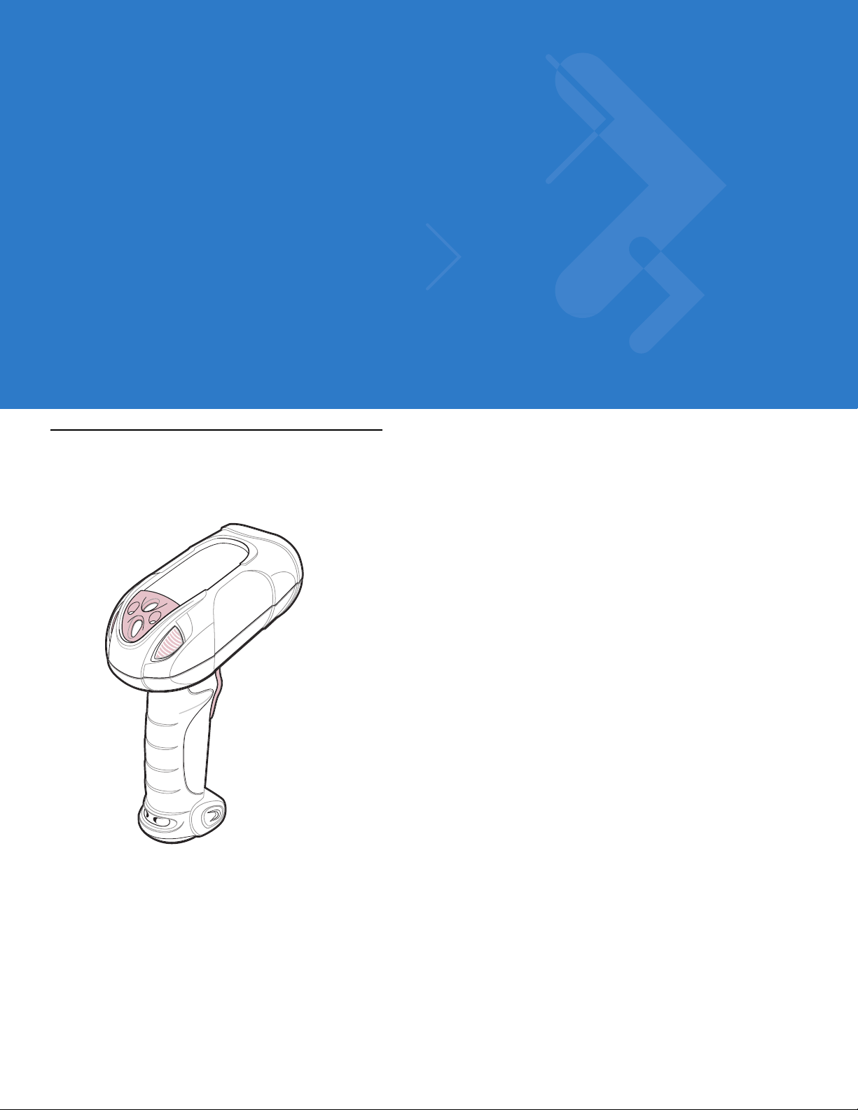
Figure 1-1
Symbol DS3478 Smart Focus Digital Scanner
Smart Focus Scanning
The digital scanner supports a Smart Focus mode which toggles the focus position after every frame between near
and far focus, optimizing decoding performance when scanning a combination of small and large bar codes. See
Focus Mode on page 5-3 to select this mode.
Page 22

1 - 2 Symbol DS3478 Product Reference Guide
Host Interfaces
This digital scanner supports the following host interfaces through communication with a cradle:
•
Standard RS-232 connection to a host.
•
Keyboard wedge connection to a host, where scanned data is interpreted as keystrokes. The following
international keyboards are supported (for Windows™ environment): North American, German, French,
French Canadian, Spanish, Italian, Swedish, UK English, Japanese, and Brazilian-Portuguese.
•
Wand emulation connection to a mobile computer, a controller, or host, which collects the data as wand data
and decodes it.
•
Scanner emulation connection to a mobile computer or a controller, which collects the data and interprets it
for the host.
•
IBM® 468X/469X hosts.
•
USB connection to a host. The digital scanner autodetects a USB host and defaults to the HID keyboard
interface type. Select other USB interface types by scanning programming bar codes. The following
international keyboards are supported (for Windows™ environment): North America, German, French,
French Canadian, Spanish, Italian, Swedish, UK English, Japanese, and Brazilian-Portuguese.
•
Synapse capability, which allows connection to a wide variety of host systems using a Synapse cable and
Synapse adapter cable. The digital scanner autodetects the Synaps e interface.
•
Configuration via 123Scan.
Unpacking the Digital Scanner
Remove the digital scanner from its packing and inspect it. If the digital scanner was damaged in transit, contact
Motorola Enterprise Mobility Support. See page xvii for contact information. KEEP THE PACKING. It is the
approved shipping container and should be used if the equipment needs to be returned for servicing.
The Digital Scanner Cradle
The digital scanner cradle serves as a stand, charger, and host interface for the digital scanner. There are two
versions of the cradle:
•
Charging cradle with radio: All communication between the cordless digit al scanne r and the host computer
occurs through the cradle. Each bar code contains programming instructions or other data unique to the bar
code pattern. The digital scanner transmits bar code data to the cradle via a wireless radio antenna. The
cradle then sends that information via an interface cable to the host computer for interpretation.
•
Charge-only cradle: This cradle serves as a sta nd and battery charger. Since one radio-enabled cradle can
receive information from up to four digital scanners, it is possible to have several charge-only cradles.
The charging cradle with radio supports two modes of operation:
•
Single point mode: the cradle communicates with one digital scanner.
•
Multipoint mode: the cradle communicates with more than one digital scanner.
The cradle sits on a desktop or mounts on a non-horizontal surface (such as a wall or forklift), depending on the
environment. For more information about mounting options and procedures, refer to the documentation included
with the cradle.
Page 23
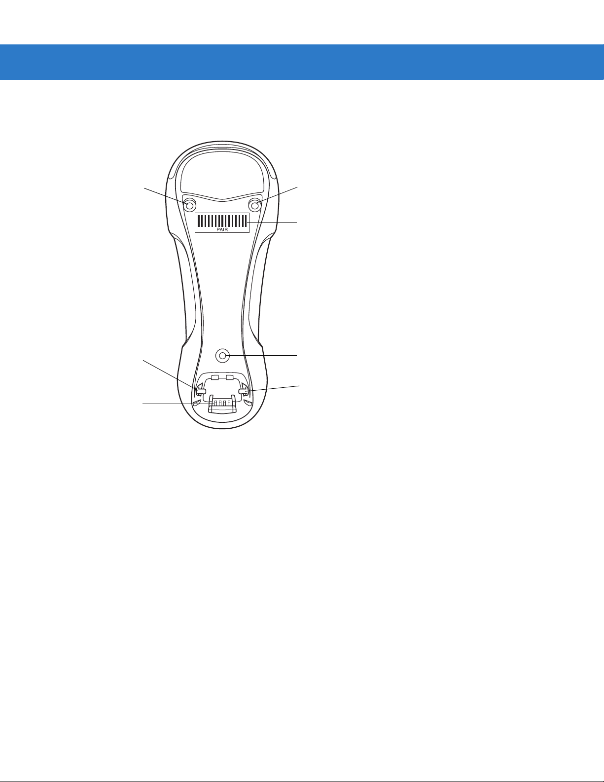
Cradle Parts
Getting Started 1 - 3
Mounting
Screw Hole
Latch
Charging/
Communications
Contacts
Figure 1-2
Cradle Front View
Mounting
Screw Hole
Pairing
Bar Code
Mounting
Screw Hole
Latch
Page 24
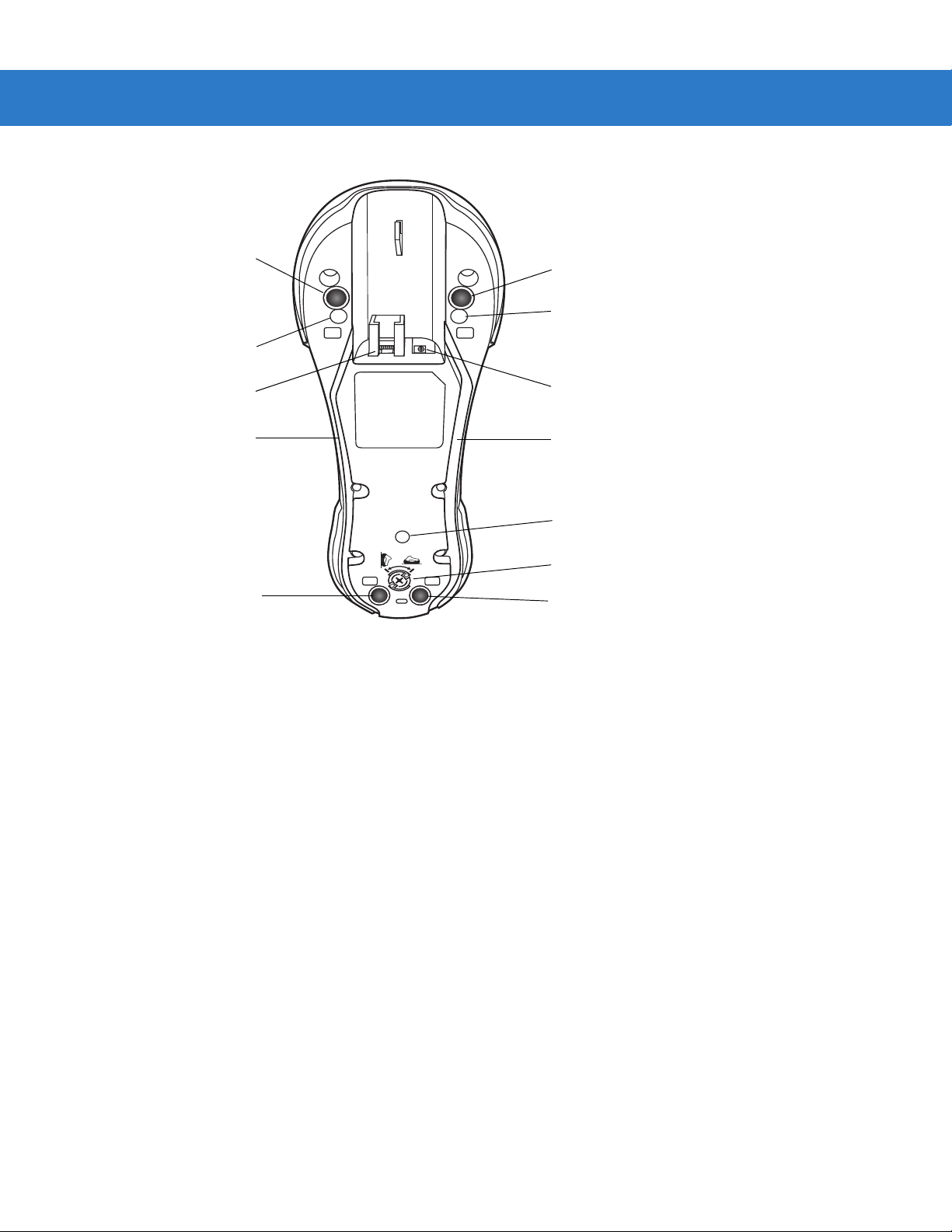
1 - 4 Symbol DS3478 Product Reference Guide
Rubber Foot
Mounting Screw Hole
Host Port
Power Cable Groove
Rubber Foot
Figure 1-3
Cradle Back View
Connecting the Cradle
Rubber Foot
Mounting Screw Hole
Power Port
Host Cable Groove
Mounting Screw Hole
Converter Knob
Rubber Foot
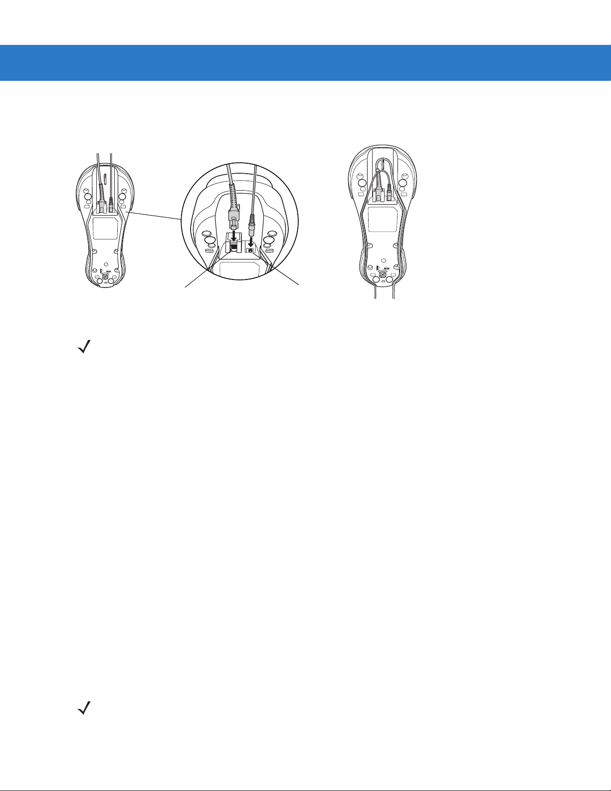
Important: Connect the interface cable and power supply in the following order to ensure proper operation of the
digital scanner and cradle. Note that this procedure includes two different power supply options.
1. Disconnect the power supply from the digital scanner cradle. See Figure 1-4.
2. Insert the modular connector of the interface cable into the host interface port on the back of the digital scanner
cradle.
3. If using a power supply that connects to the interface cable, insert this power supply into the power connector
on the interface cable, and the other end into an AC supply (see the cradle’s Quick Reference Guide for more
information).
4. Insert the other end of the inte rface cab le into the ap propriate port on the host computer (see the specific host
chapter for information on host connections).
Page 25
Getting Started 1 - 5
5. If using an external power supply, insert the power cable into the power port on the back of the digital scanner
cradle, and connect the power supply to an approved AC supply (see the cradle’s Quick Reference Guide for
more information).
Power Port
Figure 1-4
NOTE Disconnect the power supply before changing host cables, or the digital scanner may not recognize the
Host Port
Connecting the Cables to the Cradle
new host.
Different hosts require different cables. The connectors illustrated in each host chapter are examples only.
The connectors may be different from those illustrated, but the steps to connect the digital scanner are the
same.
Supplying Power to the Cradle
The cradle receives power from one of two sources:
•
An external power supply.
•
When connected to a powered host through a host cable that supplies power.
The cradle detects whether the host or an externa l supply is supplying power. It always draws power from the
external supply when available, regardless of the presence of power from a host.
Using the Host to Supply Power
When connecting the cradle to a powered host, the host can sometimes power the cradle rather than an external
power supply. Consider the following when powering from a host:
•
The digital scanner charges at a slower rate than when charging from an external power supply.
•
The cradle can charge a digital scanner only in single point mode. An external power supply is required to
charge a digital scanner in multipoint mode.
•
A powered USB port provides enough power to the cradle for charging.
•
Not all hosts provide enough power to the cradle for charging. For these hosts, connect an external power
supply.
NOTE The radio link functions normally when the cradle draws power from a host.
For more information on single and multipoint operation, see Pairing on page 1-9.
Page 26
1 - 6 Symbol DS3478 Product Reference Guide
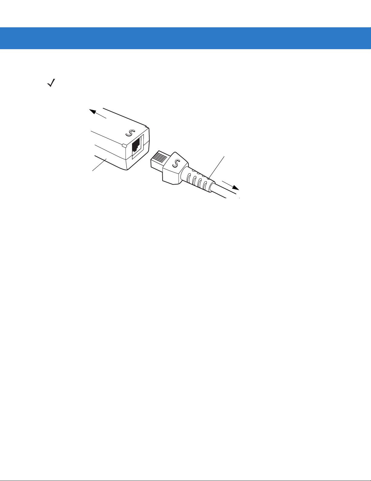
Connecting a Synapse Cable Interface
NOTE Refer to the Synapse Interface Guide provided with the Synapse cable for more information.
Synapse Smart Cables enable interfacing to a variety of hosts. The appropriate Synapse cable detects the host.
To host
Synapse Smart Cable
Synapse adapter cable
To digital scanner cradle
Figure 1-5
1. Plug the Synapse adapter cable into the bottom of the digital scanner cradle, as described in Connecting the
Synapse Cable Connection
Cables to the Cradle on page 1-5.
2. Align the ‘S’ on the Synapse adapter cable with the ‘S’ on the Synapse Smart Cable and plug the cable in.
3. Connect the other end of the Synapse Smart Cable to the host.
Reestablishing a Lost Connection to Host
If scanned data does not transmit to the cradle’s host, ensure you connected all cables securely, including the
power supply . If scanned data still does not transmit to the host, reestablish connection with the host:
1. Disconnect the power supply from the cradle.
2. Disconnect the host interf ace cable from the cradle.
3. Wait three seconds.
4. Reconnect the host interface cable to the cradle.
5. Reconnect the power supply to the cradle.
6. Re-establish pairing with the cradle.
Mounting the Cradle
For information on mounting the cradle, refer to the documentation included with the cradle.
Page 27
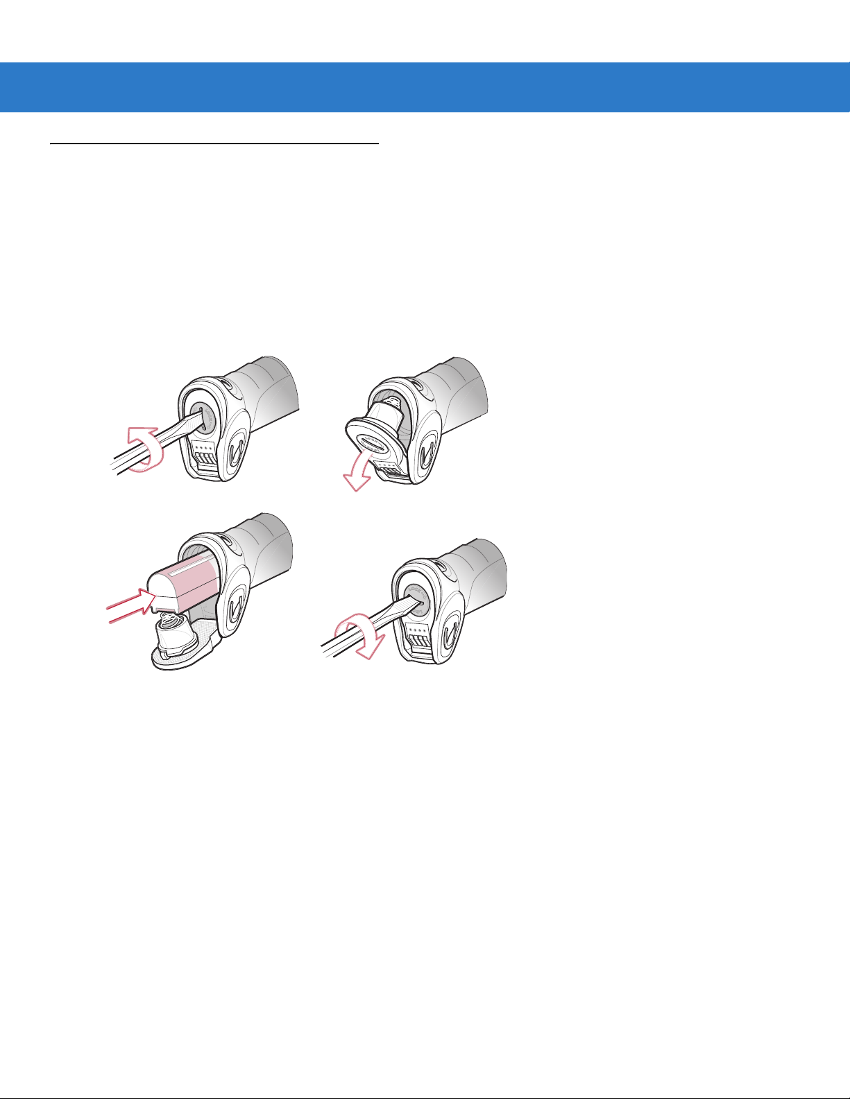
Removing and Inserting the Battery
The battery resides in a chamber in the digital scanner handle. To insert the battery:
1. Insert a coin or flathead screwdriver in the slot at the base of the digital scanner, then turn the slot
counterclockwise to release the latch.
2. Open the latch.
3. If a battery is already installed, turn the digital scanner upright to slide the battery out.
4. Slide the new battery into th e cha mber, with the rounded side toward the back and the contacts facing into the
chamber.
Getting Started 1 - 7
Figure 1-6
5. Close the latch.
6. Insert a coin or flathead screwdriver in the slot at the base of the digital scanner, press down gently, and turn
the slot clockwise to lock the latch in place.
Inserting the Battery
Page 28

1 - 8 Symbol DS3478 Product Reference Guide
Charging the Battery
For best performance, fully charge the digital scanner battery before using the digital scanner for the first time. To
charge the battery, place the digital scanner in the cradle, ensuring that the metal contacts on the bottom of the
digital scanner touch the contacts on the cradle. The battery begins charging. A complete charge can take up to
four hours, depending on the remaining charge in the battery.
Charge within the recommended temperature of 32° to 104° F (0° to 40° C) nominal, 41° to 95° F (5° to 35° C)
ideal.
Charging LED
The flashing green LED indicates charging activity. See Table 2-2 on page 2-5. If the digital scanner is charging in
fast mode (external power supply is present), the green LED blinks quickly (on for 0.25 seconds, off for 0.75
seconds). If the digital scanner is charging in slow mode (host-powered mode), the LED blinks slowly (on for 0.5
seconds, off for 1.5 seconds).
Charging Problem LED
A solid or flashing red LED during charging indicates a charging problem. See Table 2-2 on page 2-5 for definitions
of error conditions and the appropriate action to take.
Page 29
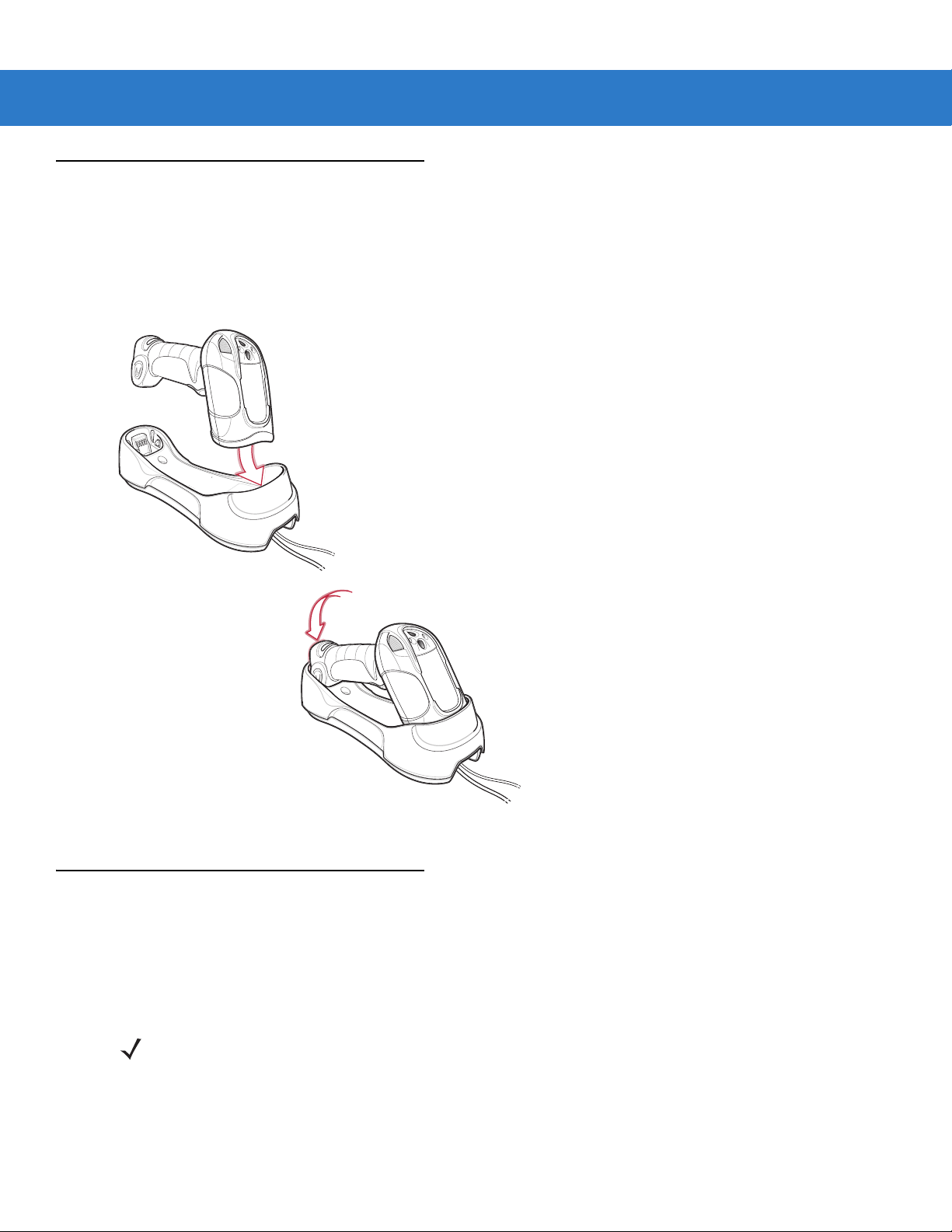
Inserting the Digital Scanner in the Cradle
Insert the digital scanner in the cradle so that the metal contacts on the bottom of the digital scanner handle touch
the contacts on the cradle:
1. With a slightly rot ated motion, insert the digital scanner into the cradle top first.
2. Push the handle down until it clicks into place, engaging the contacts in the cradle and digital scanner.
Getting Started 1 - 9
Figure 1-7
Pairing
Pairing is the process by which a digital scanner initiates communication with a cradle. The cradle has multipoint
capability, and can pair with up to four digital scanners at a time. The cradle includes a pairing bar code.
To pair the digital scanner with the cradle, scan the pairing bar code on the cradle. A short low-high beep indicates
successful pairing.
Inserting the Digital Scanner in the Cradle
NOTE The pairing bar code that connects the digital scanner to a cradle is unique to each cradle.
Do not scan data or parameters until pairing completes.
Page 30

1 - 10 Symbol DS3478 Product Reference Guide
Unpairing
Unpair the digital scanner from the cradle to make the cradle availabl e for pairing with ano ther digital scanner. Scan
the Unpairing bar code on page 4-13 to unpair the digital scanner from its cradle.
NOTE The Symbol DS3478 Quick Start Guide also includes an unpairing bar code.
Configuring the Digital Scanner
Use the bar codes in this manual or the 123Scan configuration program to configure the digital scanner. See
Chapter 4, User Preferences and each host chapter for information about programming the digital scanner using
bar code menus. See Chapter 12, 123Scan to configure the digital scanner using this configuration program.
123Scan includes a help file.
Page 31

Chapter 2 Digital Scanning
Introduction
This chapter provides beeper and LED definitions, digital scanning techniques, general scanning instructions and
tips, and decode zone diagrams.
Scan Window
Tether Plate
LED
Indicators
Scan Trigger
Figure 2-1
Parts of the Digital Scanner
Page 32

2 - 2 Symbol DS3478 Product Reference Guide
Beeper Definitions
The digital scanner emits different beeper sequences and p atterns to indicate its status. Table 2-1 defines beep
sequences that occur during both normal scanning and while programming the digital scanner.
Table 2-1
Standard Use
Short low-short medium-short high beeps Power up.
One short high beep The digital scanner successfully decoded a bar code
Four long low beeps A communication error occurred while transmitting a
Long low-high beeps Attempt to pair with the cradle was unsuccessful. Ensure
Four short high beeps Low battery indication.
Long low-high-low-high beeps Attempt to pair with a cradle that is already paired with
Five long low beeps Conversion or format error.
Low-high-low beeps ADF transmit error.
Standard Beeper Definitions
Beeper Sequence Indication
(if the decode beeper is enabled).
scanned symbol to a host. The data is ignored. This
occurs if the digital scanner is not properly configured or
if the digital scanner has disconnected from the cradle.
that the cradle has power; if not, cycle power to the
cradle and re-attempt the pairing.
the maximum number of digital scanners.
Short high-short high-short low-short low beeps Radio failure.
Cordless Digital Scanner Connection
Short low-short high beeps The digital scanner connected to the cradle after
scanning a pairing bar code or automatically after a
disconnect.
Short high-short low beeps The digital scanner disconnected from the cradle either
because the digital scanner moved out of range of the
cradle, the USB host suspended the cradle, or cradle
power was interrupted.
Parameter Menu Scanning
Short high beep Correct entry scanned or correct menu sequence
performed.
Long low-long high beeps Input error; incorrect bar code, programming sequence
or
Cancel
program mode.
Short high-short low beeps Keyboard parameter selected. Enter value using
numeric bar codes.
scanned. The digital scanner remains in ADF
Page 33

Digital Scanning 2 - 3
Table 2-1
Short high-short low-short high-short low beeps Successful program exit with change in the parameter
Code 39 Buffering
High-low beeps New Code 39 data was entered into the buffer.
Three long high beeps Code 39 buffer is full.
Low-high-low beeps The Code 39 buffer was erased or there was an attempt
Low-high beeps A successful transmission of buffered data.
Macro PDF
Two long low beeps File ID error. A bar code not in the current Macro PDF
Three long low beeps Out of memory. There is not enough buffer space to
Four long low beeps Bad symbology. Scanned a 1D or 2D bar code in a
Standard Beepe r Definitions (Continued)
Beeper Sequence Indication
setting.
to clear or transmit an empty buffer.
sequence was scanned.
store the current Macro PDF symbol.
Macro PDF sequence, a duplicate Macro PDF label, a
label in an incorrect order, or trying to transmit an empty
or illegal Macro PDF field.
Five long low beeps Flushing Macro PDF buffer.
Fast warble beep Aborting Macro PDF sequence.
Low-high beeps Flushing an already empty Macro PDF buffer.
ADF Programming Normal Data Entry
High-low beeps Enter another digit. Add leading zeros to the front if
necessary.
Low-low beeps Enter another alphabetic character or scan the
Message
High-high beeps Enter another criterion or action, or scan the
bar code.
High-low-high-low beeps Rule saved. Rule entry mode exited.
High-low-low beeps All criteria or actions cleared for current rule, continue
entering rule.
Low beep Delete last saved rule. The current rule is left intact.
Low-high-high beeps All rules have been deleted.
Short low-short high-short low-short high beeps Out of host ADF parameter storage space. Scan
Default Parameter on page 4-3
bar code.
.
End of
Save Rule
Set
Page 34

2 - 4 Symbol DS3478 Product Reference Guide
Table 2-1
ADF Programming Error Indications
Low-high-low-high beeps Out of rule memory. Erase some existing rules, then try
Low-high-low beeps Cancel rule entry. Rule entry mode exited because of an
Host Specific
Standard Beepe r Definitions (Continued)
Beeper Sequence Indication
to save rule again. (It is not necessary to re-enter the
current rule.)
error or the user asked to exit rule entry.
USB only
Four short high beeps The digital scanner did not complete initialization. Wait
several seconds and scan again.
Short low-short medium-short high beep sequence
after scanning a USB device type
Short low-short medium-short high beep sequence
occurs more than once
The digital scanner must establish communication with
the bus before it can operate at the highest power level.
The USB bus can put the digital scanner in a state where
power to the digital scanner is cycled on and off more
than once. This is normal and usually happens when the
PC cold boots.
RS-232 only
Short high beep A <BEL> character is received and Beep on <BEL> is
enabled.
Low-high beeps Entry error, wrong bar code scanned. Re-enter criterion
or action. All previously entered criteria and actions are
retained. Criteria or action list is too long for a rule.
Page 35

LED Definitions
In addition to beeper sequences, the digital scanner uses a two-color LED to indicate its status. Table 2-2 explains
LED sequences.
Digital Scanning 2 - 5
Table 2-2
Standard Use
Off No power is applied to the digital scanner, or the digital scanner is on and ready to
Green The digital scanner successfully decoded a bar code.
Red A data transmission error or digital scanner malfunction occurred.
Charging Use
Green Slow Flash The digital scanner is in the cradle and is charging in slow mode (occurs when the
Green Fast Flash The digital scanner is in the cradle and is charging in rapid mode (occurs when an
Red fast flash
(two flashes per second)
Red slow flash
(one flash per second)
Red and green flash
LED Status Indications
LED Indication
scan.
host cable powers the cradle).
external power supply powers the cradle).
Overcharge condition. Contact Motorola Enterprise Mobility Support.
Battery voltage not increasing with charge. Replace the battery.
Temperature fault. Move the cradle to a location where the temperature is 0
o
optimal charging temperature is 5
- 35o C.
o
- 40o C;
Page 36

2 - 6 Symbol DS3478 Product Reference Guide
Digital Scanning
See Chapter 1, Getting Started to install and program the digital scanner. Also see DPM Scanning on page 5-5 for
DS3478-DP (DPM) digital scanning. To scan:
1. Aim the digital scanner at the bar code.
2. Press the scan trigger.
Figure 2-2
Aiming the Digital Scanner
The digital scanner projects a red laser aiming pattern which allows positioning the bar code or object within
the field of view.
Figure 2-3
Laser Aiming Pattern
If necessary, the digital scanner turns on its red LEDs to illuminate the target bar code.
3. Center the symbol in any orienta tion within the aiming pattern. Be sure the entire symbol is within the
rectangular area formed by the brackets in the pattern.
1D bar code symbol
2D bar code symbol
2D dot peen DPM symbol
Figure 2-4
Aiming Pattern
Centering Symbol in Aiming Pattern
Page 37

Digital Scanning 2 - 7
4. Hold the trigger until the digital scanner beeps, indicating it successfully decoded the bar code. For more
information on beeper and LED definitions, see Table 2-1 and Table 2-2.
This process usually occurs instantaneo usly. Steps 2 - 4 are repeated on poor quality or dif ficult bar code s, until the
bar code decodes, you release the trigger, or the Decode Session Timeout occurs.
NOTE Scanning Direct Part Marks (DPMs) with the DS3478-DP (DPM) Digital Scanner: Due to the reflective
nature of some surfaces used with DPMs (see Figure 2-4 on page 2-6), to achieve the best results when
scanning DPMs, tilt the scanner at an angle relative to the target (25-45 degrees is recommended). As a
guide, if you are decoding a 23 mil dot peen mark and the scanner is set to the near field focus, present
the target between one and four inches from the nose of the scanner at a minimum tilt of 30 degrees.
When scanning standard (non-DPM) bar codes with any configuration of the DS3478 digital scanner,
follow the standard aiming instructions described in Aiming.
Aiming
Hold the digital scanner between two and nine inches (depending on symbol density; see Decode Zones on page
2-8) from the symbol, centering the aiming pattern cross hairs on the symbol.
The aiming pattern is smaller when the digital scanner is closer to the symbol an d larger when it is farthe r from the
symbol. Scan symbols with smaller bars or elements (mil size) closer to the digital scanner, and those with larger
bars or elements (mil size) farther from the digital scanner.
The digital scanner can also read a bar code within the aiming pattern but not centered. The top examples in
Figure 2-5 show acceptable aiming options, while the bottom examples do not decode.
Figure 2-5
012345
012345
Acceptable and Incorrect Aiming
012345
012345
Page 38

2 - 8 Symbol DS3478 Product Reference Guide
Decode Zones
DS3478-SF Near Focus - 1D and PDF417
Note: Typical performance at 73°F (23°C)
on high quality symbols in normal room light.
Vcc = 3.3V
Top of
scanner
2.0
2.3
1.3
1.8
0.8
*
*
15 mil PDF417
5 mil
6.67 mil PDF417
7.5 mil
10 mil PDF417
13 mil (100% UPC)
20 mil
5.5
4.5
5.8
6.0
6.3
7.3
9.5
in.
2.5
1.25
1.25
2.5
0
cm
6.35
3.18
0
3.18
6.35
W
i
d
t
h
o
f
F
i
e
l
d
In.
cm
Figure 2-6
0
0
2
5.1
468
10.2
15.2
20.3
10
25.4
Depth of Field
* Minimum distance determined by symbol length and scan angle.
Symbol DS3478-SF Near Focus Decode Zone - 1D and PDF417
Page 39

DS3478-SF Near Focus - 2D Codes
Digital Scanning 2 - 9
Note: Typical performance at 73°F (23°C)
on high quality symbols in normal room light.
Vcc = 3.3V
Top of
scanner
1.79
1.58
1.25
1.71
1.21
5 mil Data Matrix
5 mil QR Code
2.07
7.5 mil
Data Matrix
10 mil Data Matrix
3.00
7.5 mil QR Code
10 mil QR Code
3.58
4.25
4.54
4.83
5.00
in.
0.75
0.75
1.5
1.5
cm
0
3.8
1.9
1.9
3.8
W
i
d
t
h
o
0
f
F
i
e
l
d
In.
cm
Figure 2-7
0
0
1.0
2.5
2.0 3.0 4.0
5.1
7.6
10.2
5.0
12.7
Depth of Field
* Minimum distance determined by symbol length and scan angle.
Symbol DS3478-SF Near Focus Decode Zone - 2D Codes
Page 40

2 - 10 Symbol DS3478 Product Reference Guide
DS3478-SF Far Focus
Note: Typical performance at 73°F (23°C)
on high quality symbols in normal room light.
Vcc = 3.3V
Top of
scanner
5 mil
5.0
6.0
7.5 mil
2.8
10 mil PDF417
4.3
1.5
*
*
13 mil (100% UPC)
15 mil PDF417
8.5
8.8
12.3
20 mil
14.5
20.0
in.
5.5
2.75
0
2.75
5.5
cm
14.0
7.0
7.0
14.0
W
i
d
t
h
o
0
f
F
i
e
l
d
In.
cm
Figure 2-8
0
0
5
12.7 25.4
10 15
38.1
20
50.8
Depth of Field
* Minimum distance determined by symbol length and scan angle.
Symbol DS3478-SF Far Focus Decode Zone
Page 41

DS3478-SF Smart Focus
Note: Typical performance at 73°F (23°C)
on high quality symbols in normal room light.
Vcc = 3.3V
Top of
scanner
5 mil
2.0
6.67 mil PDF417
2.3
1.3
0.8
*
*
7.5 mil
1.8
15 mil PDF417
6.0
4.5
8.5
10 mil PDF417
8.8
13 mil (100% UPC)
20 mil
12.3
14.5
20.0
in.
5.5
2.75
0
2.75
5.5
cm
14.0
14.0
7.0
0
7.0
Digital Scanning 2 - 11
W
i
d
t
h
o
f
F
i
e
l
d
In.
cm
Figure 2-9
0
0
5
12.7 25.4
10 15
38.1
20
50.8
Depth of Field
* Minimum distance determined by symbol length and scan angle.
Symbol DS3478-SF Smart Focus Decode Zone
Page 42

2 - 12 Symbol DS3478 Product Reference Guide
DS3478-HD/DPM Near Focus - 1D and PDF417
Note: Typical performance at 73°F (23°C)
on high quality symbols in normal room light.
Vcc = 3.3V
Top of
scanner
in.
2.0
1.0
cm
0
5.1
2.5
W
i
d
t
h
o
0
f
In.
cm
Figure 2-10
5.1
F
i
e
l
d
4 mil PDF417
3.7
2.9
1.64
10 mil PDF417
*
*
*
20 mil Dot Peen (DPM Version Only)
1.4
0
0
5 mil
6.67 mil PDF417
2.5
2.1
15 mil PDF417
7.5 mil
13 mil (100% UPC)
2.7
2.7
2
5.1
4.1
20 mil
468
10.2
4.5
4.5
4.8
5.0
5.6
15.2
7.5
20.3
1.0
2.0
2.5
Depth of Field
* Minimum distance determined by symbol length and scan angle.
DS3478-HD/DPM Near Focus Decode Zone - 1D and PDF417
Page 43

DS3478-HD/DPM Near Focus - 2D Codes
Digital Scanning 2 - 13
Note: Typical performance at 73°F (23°C)
on high quality symbols in normal room light.
Vcc = 3.3V
Top of
scanner
0.88
0.63
0.58
0.5
0.83
0.83
0.67
0.33
4 mil Data Matrix
5 mil Data Matrix
7.5 mil
Data Matrix
10 mil Data Matrix
4 mil QR Code
5 mil QR Code
7.5 mil QR Code
10 mil QR Code
1.63
1.92
1.96
2.00
2.38
2.34
2.42
2.54
in.
0.7
0.35
0.35
0.7
0
cm
1.8
0.9
0
0.9
1.8
W
i
d
t
h
o
f
F
i
e
l
d
In.
cm
Figure 2-11
0
0
0.5
1.3
1.0 1.5 2.0
2.5
3.8
5.1
2.5
6.4
Depth of Field
* Minimum distance determined by symbol length and scan angle.
DS3478-HD/DPM Near Focus Decode Zone - 2D Codes
Page 44
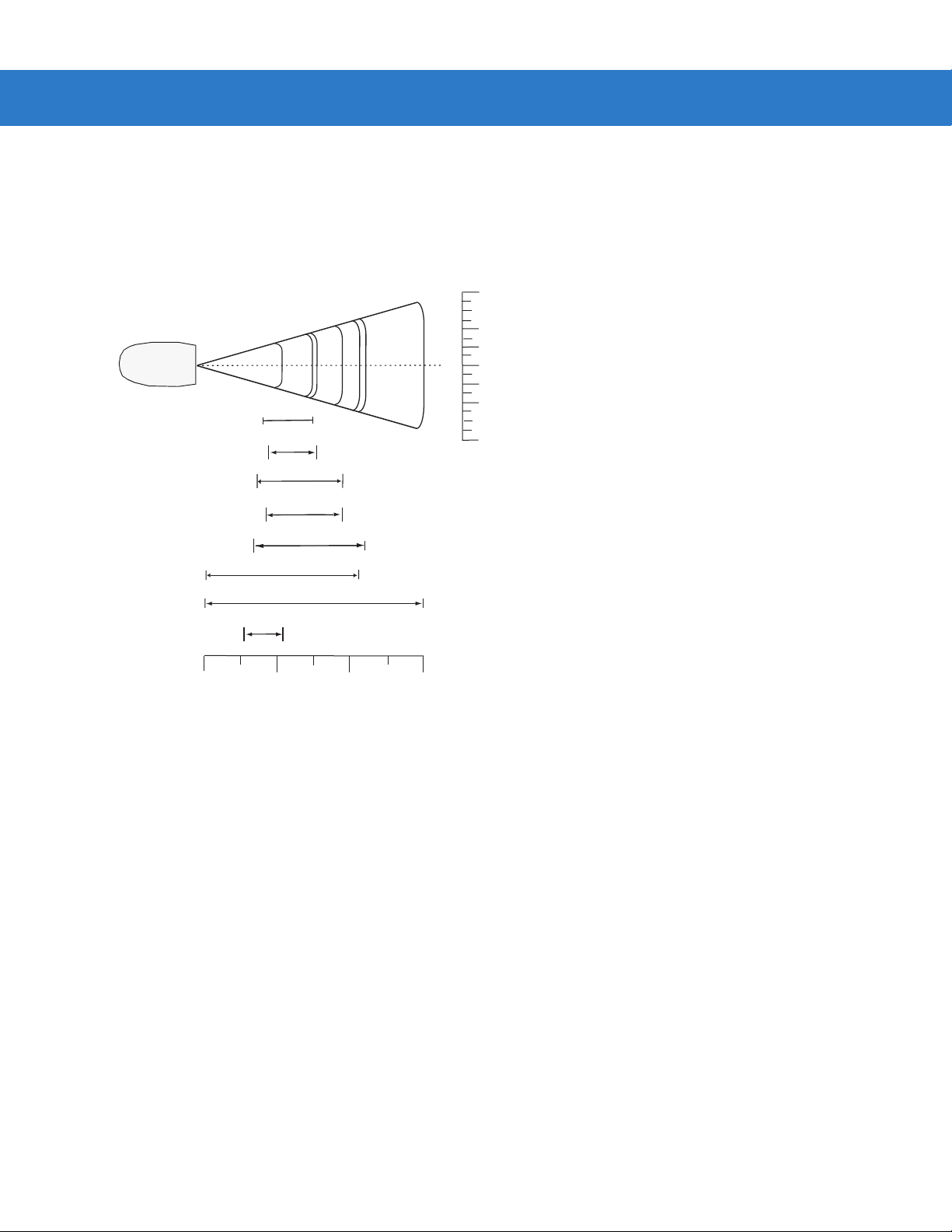
2 - 14 Symbol DS3478 Product Reference Guide
DS3478-HD/DPM Far Focus
Note: T ypical perf or mance at 73°F (23°C)
on high quality symbols in nor mal room light.
Vcc = 3.3V
Top of
scanner
in.
4
2
0
cm
10.2
5.1
W
i
d
t
h
o
0
f
In.
cm
* Minimum distance determined by symbol length and scan angle.
Figure 2-12
5 mil
7.5 mil
5
5.3
7.5
7.6
9.5
9.5
11.0
10.7
20 mil
10 15
15.0
38.1
4.0
6.67mil PDF417
4.5
3.2
10 mil PDF417
4.3
13 mil (100% UPC)
3.0
*
*
20 mil Dot Peen (DPM Version Only)
15 mil PDF417
2.6
0
0
12.7 25.4
Depth of Field
DS3478-HD/DPM Far Focus Decode Zone
5.1
2
4
10.2
F
i
e
l
d
Page 45

DS3478-HD/DMP Smart Focus
Note: T ypical perf or mance at 73°F (23°C)
on high quality symbols in nor mal room light.
Vcc = 3.3V
Top of
scanner
in.
4
2
0
cm
10.2
5.1
Digital Scanning 2 - 15
W
i
d
t
h
o
0
f
20 mil Dot Peen (DPM Version Only)
In.
cm
* Minimum distance determined by symbol length and scan angle.
Figure 2-13
2
4
1.64
2.5
2.1
*
*
*
1.4
0
0
5 mil
6.67mil PDF417
10 mil PDF417
13 mil (100% UPC)
2.7
15 mil PDF417
7.5 mil
5.3
7.5
7.6
20 mil
5
12.7 25.4
9.5
9.5
11.0
10.7
15.0
10 15
38.1
Depth of Field
DS3478-HD/DPM Smart Focus Decode Zone
5.1
10.2
F
i
e
l
d
Page 46

2 - 16 Symbol DS3478 Product Reference Guide
Page 47

Chapter 3 Maintenance and Technical
Specifications
Introduction
This chapter provides digital scanner maintenance and troubleshooting information, technical specifications, and
signal descriptions (pinouts).
Maintenance
Cleaning the scan window is the only maintenance required. A dirty window can affect scanning accuracy.
•
Do not allow any abrasive material to touch the window.
•
Remove any dirt particles with a damp cloth.
•
Wipe the window using a tissue moistened with ammonia/water.
•
Do not spray water or other cleaning liquids directly onto the window.
Page 48

3 - 2 Symbol DS3478 Product Reference Guide
Troubleshooting
Table 3-1
Nothing happens when the
scan trigger is pressed.
The digital scanner emits short
low-short medium-short high
beep sequence.
The digital scanner emits short
high-short high-short
low-short-low beep sequence.
Troubleshooting
Problem Possible Causes Possible Solutions
No power to the digital
scanner.
The digital scanner is
disabled.
If using RS-232 Nixdorf B
mode, CTS is not asserted.
The aiming pattern is
disabled.
Decoding illumination is
disabled.
The digital scanner is
powering up.
Radio failure. Cycle power to the cradle and re-attempt pairing.
Check battery.
Ensure that end cap to battery chamber is
secured.
For Synapse or IBM 468x mode, enable the digit al
scanner via the host interface. Otherwise, see the
technical person in charge of scanning.
Assert CTS line.
Enable the aiming pattern. See
Pattern on page 5-4
Enable illumination. See
page 5-4
Normal when battery is inserted.
.
.
Decoding Illumination on
Decode Aiming
The digital scanner emits the
aiming pattern, but does not
decode the bar code.
The digital scanner emits four
short high beeps.
Digital scanner is not
programmed for the correct
bar code type.
Bar code symbol is
unreadable.
Bar code is out of range
from the digital scanner.
The symbol is not
completely inside aiming
pattern.
Battery is low. Charge the battery. See
Ensure the digital scanner is programmed to read
the type of bar code being scanned.
Check the symbol to ensure it is not defaced. Try
scanning test bar codes of the same bar code
type. See
bar codes.
Move digital scanner closer to or further from bar
code.
Move the symbol completely within the aiming
pattern.
page 1-8
Appendix C, Sample Bar Codes
.
for test
Charging the Battery on
Page 49

Maintenance and Technical Specifications 3 - 3
Table 3-1
The digital scanner emits a
disconnect (short high-short
low) beep sequence.
The digital scanner emits four
long low beeps after scanning
a bar code.
Troubleshooting (Continued)
Problem Possible Causes Possible Solutions
The digital scanner
disconnected from the
cradle because it is too far
from the cradle.
The digital scanner
disconnected from the
cradle because the cradle
lost power or was placed in
USB suspend mode.
The cradle did not complete
USB initialization.
The incorrect host interface
cable is used.
The interface/power cables
to the cradle are loose.
The digital scanner is not
paired to a cradle.
Move closer to the cradle and listen for a
reconnection beep (short low-short high).
Check power connections to the cradle, and if
using a USB cable, check to make sure the host
computer has not entered a power save mode.
Wait several seconds and scan again.
Connect the correct host interface cable.
Secure all cable connections.
Scan the PAIR bar code on the cradle connected
to the host that is to receive data.
The digital scanner decodes
the bar code, but does not
transmit the data to the host.
The digital scanner emits five
long low beeps after decoding
a bar code.
The digital scanner
disconnected.
A transmission error was
detected.
The digital scanner is not
paired to the host-connected
interface.
The cradle is not
programmed for the correct
host interface.
The interface cable is loose. Secure all cable connections.
The cradle lost connection
to the host.
A conversion error or format
error occurred.
See previous disconnect beep sequence.
Ensure the cradle’s communication parameters
match the host's setting.
Pair the digital scanner to the cradle (using the
PAIR bar code on the cradle).
Check digital scanner host parameters or edit
options.
See
Reestablishing a Lost Connection to Host on
page 1-6
Properly configure the digital scanner’s conversion
parameters.
.
Page 50

3 - 4 Symbol DS3478 Product Reference Guide
Table 3-1
Troubleshooting (Continued)
Problem Possible Causes Possible Solutions
The host displays scanned
data incorrectly.
The digital scanner emits short
high-short high- short high-long
low beep sequence when it is
not in use.
The digital scanner emits long
low-long high beep sequence
during programming.
The digital scanner emits short
low-short high- short low-short
high beep sequence during
programming.
The cradle’s host
communication parameters
do not match the host’s
parameters.
Select the correct host.
For RS-232, ensure the cradle’s communication
parameters match the host’s settings.
For a Keyboard Wedge configuration, prog ram the
system for the correct keyboard type, and turn off
the CAPS LOCK key.
Properly program editing options (e.g., UPC-E to
UPC-A conversion).
RS-232 receive error. Normal during host reset. Otherwise, ensure the
digital scanner’s RS-232 parity setting matches the
host setting.
Input error or
code was scanned.
Out of ADF parameter
Cancel
bar
Scan the correct numeric bar codes within range
for the parameter programmed.
Erase all rules and re-program with shorter rules.
storage space.
Out of Synapse parameter
storage space.
Scan
Set Synapse Defaults
bar code from the
appropriate Synap se Interface Guide for cables no
longer in use and re-program the digital scanner
for the current host interface.
The digital scanner emits
Clearing Code 39 buffer. Normal when scanning the Code 39 Buffering
low-high-low beeps.
The digital scanner emits one
short high beep when it is not in
In RS-232 mode, a <BEL>
character is received.
use.
The digital scanner emits short
low-short medium-short high
The digital scanner is
powering up.
beep sequence.
The battery does not charge. The cradle is outside the
charging temperature range.
The battery door falls off. The digital scanner was
dropped.
NOTE If problems still occur, contact the distributor or Motorola Enterprise Mobility Support. See page xvii for
contact information.
Clear Buffer
bar code or upon attempt to transmit
an empty Code 39 buffer.
Normal when
Beep on <BEL>
is enabled and the
digital scanner is in RS-232 mode.
Normal when the battery is inserted.
Charge within the recommended temperature of
32° to 104° F
(0° to 40° C) nominal, 41° to 95° F (5° to 35° C)
ideal.
Snap the battery door back in to reinstall.
Page 51

Technical Specifications
Maintenance and Technical Specifications 3 - 5
Table 3-2
Battery Rechargeable Lithium-Ion 2200 mAh (3.7V)
Decode Capability UPC/EAN, UPC/EAN with supplementals, Bookland EAN, JAN 8 & 13, Coupon Code,
Beeper Operation User-selectable: Enable, Disable
Beeper Volume User-selectable: Three levels
Beeper Tone User-selectable: Three tones
Field of View 30º +/- 2º horizontal
Yaw Tolerance ± 50° from nominal
Pitch Tolerance ± 60° from nominal
Roll Tolerance ± 180° from nominal
Technical Specifications - Symbol DS3478 Digital Scanner
Item Description
Code 128, GS1-128, Code 39, Code 39 Full ASCII, Code 39 Trioptic, Code 32, Code
93, Code 11, Interleaved 2 of 5, Discrete 2 of 5, IATA 2 of 5, Codabar (NW7), MSI,
Inverse 1D, US Postnet, US Planet, UK Postal, Japan Postal, Australia Postal, Dutch
Postal, 4State Postal, GS1 DataBar, Composite Codes, PDF417, MicroPDF,
Maxicode, Data Matrix (ECC 200), QR Code, MicroQR, QR Inverse, Aztec, Aztec
Inverse, DPM (DPM version only).
22.5º +/- 2º vertical
Print Contrast Minimum 25% minimum reflectance differential, measured at 650 nm.
Ambient Light Immunity 10,000 Ft Candles (107,600 Lux)
Durability 6.5 ft (2.0 m) drops to concrete
Operating Temperature -4° to 122° F (-20° to 50° C)
Storage Temperature -40° to 140° F (-40° to 60° C)
Charging Temperature 32° to 104° F (0° to 40° C) nominal, 41° to 95° F (5° to 35° C) ideal
Humidity 5% to 95% (non-condensing)
ESD 15 kV air discharge
8 kV contact discharge
Weight 14.6 oz (414 grams)
Dimensions:
Height
Width
Depth
Laser 650nm laser diode
7.34 in. (18.65 cm)
4.82 in. (12.25 cm)
2.93 in. (7.43 cm)
Page 52

3 - 6 Symbol DS3478 Product Reference Guide
Table 3-2
Laser Classification EN60950-1 1994 + A1:2002 + A2:2001
Minimum Element Width 5 mil (0.127 mm)
Interfaces Supported Keyboard Wedge, RS-232, USB, IBM 468X/469X, Wand Emulation, Scanner
Radio Link Bluetooth Class 1/Class 2 (2.4 GHz)
Electrical Safety Certified to UL60950-1, CSA 22.2 No. 60950-1, EN60950-1/IEC60950-1
Input Transient Protection EN301 489-1 Clause 9.4, EN301 489-17 Clause 6 Section 1
EMI FCC Part 15 Class B, ICES-003 Class B, EN 55022 1994 A1:1995 + A2:1997, Japan
Table 3-3
Power Requirements 4.75 - 14.0 VDC
Technical Specifications - Symbol DS3478 Digital Scanner (Continued)
Item Description
IEC60825-1 1993 + A1:1997 + A2:2001
Emulation, Synapse, 123Scan
VCCI
Technical Specifications - STB 3478 Cradle
Item Description
Typical Current Draw
Not Charging: 105 mA @ 5V
45 mA @ 9V
Fast Rate Charge: 955 mA @ 5V
660 mA @ 9V
Slow Rate Charge: 480 mA @ 5V
345 mA @ 9V
Interfaces Supported Keyboard Wedge, RS-232, USB, IBM 468X/469X, Wand Emulation,
Scanner Emulation, Synapse
Operating Temperature -4° to 122° F (-20° to 50° C)
Storage Temperature -40° to 140° F (-40° to 60° C)
Charging Temperature 32° to 104° F (0° to 40° C) nominal, 41° to 95° F (5° to 35° C) ideal
Humidity 5% to 95% (non-condensing)
ESD 15 kV air discharge
8 kV contact discharge
Weight 10.5 oz (298 grams)
Dimensions:
Height
Width
Depth
9.5 in. (24.1 cm)
4.0 in (10.2 cm)
2.9 in (7.4 cm)
Page 53

Maintenance and Technical Specifications 3 - 7
Table 3-3
Radio Link Bluetooth Class 1/Class 2 (2.4 GHz)
Electrical Safety Certified to UL60950-1, CSA 22.2 No. 60950-1, EN60950-1/IEC60950-1
Input Transient Protection EN301 489-1 Clause 9.4, EN301 489-17 Clause 6 Section 1
EMI FCC Part 15 Class B, ICES-003 Class B, EN 55022 1994 A1:1995 + A2:1997,
Technical Specifications - STB 3478 Cradle (Continued)
Item Description
Japan VCCI
Digital Scanner Signal Descriptions
Figure 3-1 illustrates the positions of the cradle’s host port pins.
Pin 10Pin 1
Figure 3-1
Cradle to Host Pin Assignments
The signal descriptions in Table 3-4 apply to the 10-pin RJ connector on the digital scanner cra dle and are for
reference only.
Table 3-4
Pin IBM Synapse RS-232
1 Reserved SynClock Reserved Reserved Reserved Jump to Pin 6 DBP
2 Power Power Power Power Power Power Power
3 Ground Ground Ground Ground Ground Ground Ground
4 IBM_A(+) Reserved TxD KeyClock DBP Reserved SOS
5 Reserved Reserved RxD TermData CTS D + Decode
6 IBM_B(-) SynData RTS KeyData RTS Jump to Pin 1 Trigger
7 Reserved Reserved CTS TermClock Reserved D - Enable
8 Reserved Reserved Reserved Reserved Reserved Reserved Reserved
9 Reserved Reserved Reserved Reserved Reserved Reserved Reserved
10 Reserved Reserved Reserved Reserved Reserved Reserved Reserved
Digital Scanner Cradle to Host Pin-outs
Keyboard
Wedge
Wand USB
Scanner
Emulation
Page 54
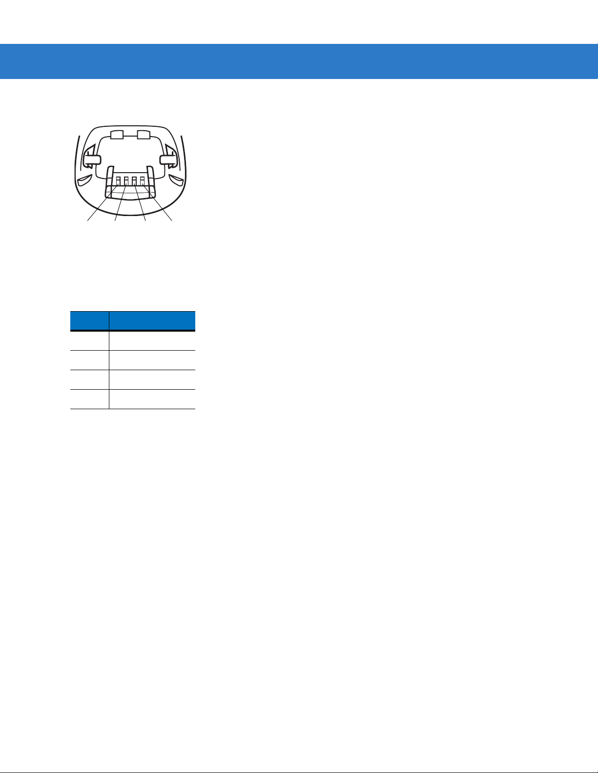
3 - 8 Symbol DS3478 Product Reference Guide
Figure 3-2 illustrates the positions of the digital scanner’s cradle port pins.
Pin 4 Pin 3 Pin 2
Figure 3-2
Cradle Pin Assignments
Pin 1
The signal descriptions in Table 3-5 apply to the connector from the digital scanner to the scanner cradle and are
for reference only.
Table 3-5
Digital Scanner to Scanner Cradle Pin-outs
Pin Description
1VCC
2CRADLE_TXD
3 CRADLE_RXD
4GND
Page 55

Chapter 4 User Preferences
Introduction
This chapter describes each user preferen ce fea tu re and provides programming bar codes for selecting these
features for the digital scanner.
The digital scanner ships with the settings shown in the User Preferences Default Table on page 4-2 (also see
Appendix A, Standard Defaul t Parameters for all host and miscellaneous defaults). If the default values suit the
requirements, programming is not necessary.
Set feature values by scanning single bar codes or short bar code sequences. The settings are stored in
non-volatile memory and are preserved when you power down the digital scanner.
The digital scanner communicates with the host through the digital scanner cradle. During setup, you pair the
digital scanner with a cradle, which connects to the host through o ne of several interfa ces (see Pairing on page 1-9
and the applicable host interface chapter). Each cradle can pair with up to four digital scanners.
If not using a Synapse or USB cable, select the host type (see the specific host chapter) after the digital scanner
emits power-up beeps. This is only necessary upon the first power-up when connecting to a new host.
NOTE Disconnect the power supply before changing host cables or the digital scanner may not recognize the
new host.
To return all features to their default values, scan Set All Defaults on page 4-3. Throughout the programming bar
code menus, asterisks (
*) indicate default values.
* Indicates Default
*Medium Frequency
Feature/Option
Page 56

4 - 2 Symbol DS3478 Product Reference Guide
Scanning Sequence Examples
In most cases, scan only one bar code to set a parameter value. For example, to set the beeper tone to high, scan
the High Frequency (beeper tone) bar code under Beeper Tone on page 4-4. The digital scanner issues a fast
warble beep and the LED turns green, indicating a successful parameter en try.
Other parameters, such as Decode Session Timeout, require scanning several bar codes. See the parameter
description for this procedure.
Errors While Scanning
Unless otherwise specified, if you make an error during a scanning sequence, re-scan the correct parameter.
User Preferences Default Parameters
T able 4-1 lists the default s for user preference p arameters. To change any option, scan the appropriate bar code (s)
provided in User Preferences on page 4-3.
NOTE See Appendix A, Standard Default Parameters for all user preference, host, symbology, and
miscellaneous default parameters.
Table 4-1
User Preferences
Set Default Parameter All Defaults
Parameter Scanning Enable
Beeper Tone Medium
Beeper Volume High
Power Mode Reduced
Beep After Good Decode Enable
Picklist Mode Dis abled Always
Decode Session Timeout 3.0 seconds
Fuzzy 1D Decoding Enable
Decode Mirror Images Never
User Preferences Default Table
Parameter Default
Page
Number
4-3
4-3
4-4
4-5
4-5
4-6
4-7
4-8
4-8
4-9
Connection Maintenance Interval 15 minutes
Radio Output Power Bluetooth Class 1
Parameter Broadcast Enable
Single Point/Multipoint Operation Single Point
4-10
4-12
4-12
4-13
Page 57

User Preferences
Set Default Parameter
Scan this bar code to return all parameters to the default values listed in Table A-1 on page A-1.
Parameter Scanning
To disable decoding of parameter bar codes, scan the Disable Parameter Scanning bar code be low . Note that the
digital scanner can still decode the Set Defaults parameter b ar code. To enable decoding of paramete r bar co des,
either scan Enable Parameter Scanning or Set All Defaults.
User Preferences 4 - 3
Set All Defaults
*Enable Parameter Scanning
Disable Parameter Scanning
Page 58

4 - 4 Symbol DS3478 Product Reference Guide
Beeper Tone
To select a decode beep frequency (tone), scan the Low Frequency, Medium Frequency, or High Frequency bar
code.
Low Frequency
*Medium Frequency
High Frequency
Page 59

Beeper Volume
To select a beeper volume, scan the Low Volume, Medium Volume, or High Volume bar code.
Low Volume
Medium Volume
User Preferences 4 - 5
*High Volume
Power Mode
This parameter determines whether or not the digital scanner enters reduced power mode after a decode attempt.
When in reduced power mode, the digital scanner draws less current from its battery.
Continuous On
*Reduced Power Mode
Page 60

4 - 6 Symbol DS3478 Product Reference Guide
Beep After Good Decode
Scan one of the following bar codes to select whether the digital scanner beeps after a good decode. If you select
Do Not Beep After Good Decode, the beeper still operates during parameter menu scanning and indicates error
conditions.
*Beep After Good Decode
(Enable)
Do Not Beep After Good Decode
(Disable)
Page 61

User Preferences 4 - 7
Picklist Mode
Parameter # F0h 92h
Picklist mode enables the digital scanner to decode only bar codes that are aligned under the laser crosshair.
Select one of the following picklist modes for the digital scanner:
•
Disabled Always (default) - Picklist mode is always disabled.
•
Enabled Out of Scanstand - Picklist mode is enabled when the digital scanner is out of presentation
(scanstand) mode and disabled when the digital scanner is in presentation mode.
•
Enabled Always - Picklist mode is always enabled.
NOTE If you enabled DPM Scanning on page 5-5, disable Picklist Mode when scanning a DPM bar code.
Picklist performance is not guaranteed for DPM bar codes.
*Disabled Always
(00h)
Enabled Always
(02h)
Enabled Out of Scanstand
(01h)
Page 62

4 - 8 Symbol DS3478 Product Reference Guide
Decode Session Timeout
This parameter sets the maximum time decode processing continues during a scan attempt. It is programmable in
0.1 second increments from 0.5 to 9.9 seconds. The default timeout is 3.0 seconds.
To set a Decode Session Timeout, scan the bar code below. Next, scan two numeric bar codes from Appendix D,
Numeric Bar Codes that correspond to the desired on time. Enter a leading zero for single digit numbers. For
example, to set a Decode Session Timeout of 0.5 seconds, scan the bar code below, then scan the 0 and 5 bar
codes. To correct an error or change the selection, scan Cancel on page D-3.
Decode Session Timeout
Fuzzy 1D Decoding
Enable this parameter to increase aggressiveness when decoding significantly damaged 1D symbols. Disabling
this parameter reduces decode aggressiveness on such symbols, but increases decode aggressiveness on 2D
symbols.
NOTE 123Scan does not support this option.
Disable Fuzzy 1D Decoding
*Enable Fuzzy 1D Decoding
Page 63

Decode Mirror Images (Data Matrix Only)
Parameter # F1h 19h
Select an option for decoding mirror image Data Matrix bar codes:
•
Always - decode only Data Matrix bar codes that are mirror images
•
Never - do not decode Data Matrix bar codes that are mirror images
•
Auto - decode both mirrored and unmirrored Data Matrix bar codes.
*Never
(00h)
User Preferences 4 - 9
Auto
(02h)
Always
(01h)
Page 64

4 - 10 Symbol DS3478 Product Reference Guide
Radio Communications
Connection Maintenance Interval
When a digital scanner disconnects from a cradle due to a Link Supervision Timeout, the digital scanner
immediately attempts to reconnect to the cradle for 30 seconds. If the digital scanner does not reconnected within
30 seconds, it enters low power mode. Thereafter, when you scan a bar code, the digital scanner attempts to
reconnect before transmitting the data.
To guarantee that a disconnected digital scanner can reconnect when it comes back in range, the cradle reserves
the connection for that digital scanner for a period of time defined by the Connection Maintenance Interval. If the
cradle already supports the maximum four digital scanners, and one digital scanner disconnects, a fifth digital
scanner cannot pair to the cradle during this interval. Connection Maintenance Interval options are:
•
15 minutes
•
30 minutes
•
One hour
•
Two hours
•
Four hours
•
Eight hours
•
24 hours
•
Indefinitely.
Considerations
The system administrator determines the Connection Maintenance Interval. A shor ter interval allows new users to
gain access to abandoned connections more quickly, but causes problems if users leave the work area for
extended periods. A longer interval allows existing users to leave the work area for longer periods of time, but ties
up the system for new users.
To avoid this conflict, users who are going off-shift can scan the unpair bar code on page 4-13 to ignore the
Connection Maintenance Interval and make the connection immediately available.
To set the Connection Maintenance Interval, select one of the following bar codes.
*Set Interval to 15 Minutes
Set Interval to 30 Minutes
Page 65

Connection Maintenance Interval (continued)
Set Interval to 60 Minutes
User Preferences 4 - 11
Set Interval to 2 Hours
Set Interval to 4 Hours
Set Interval to 24 Hours
Set Interval to 8 Hours
Set Interval to Forever
Page 66

4 - 12 Symbol DS3478 Product Reference Guide
Radio Output Power
The Symbol DS3478 uses a Class 1 Bluetooth radio with a transmission rang e of up to 100m. Optionally pla ce the
radio in Class 2 operating mode to restrict the transmission range to 10m and reduce the effect of the radio on
neighboring wireless systems.
Scan a bar code to select Class 1 or Class 2 operation.
*Bluetooth Class 1
Bluetooth Class 2
Parameter Broadcast
Enable Parameter Broadcast to broadcast all parameter bar codes scanned to all other digital scanners in the
piconet. Disable this to process parameter bar codes by the individual digital scanner only, and the digital scanner
ignores parameters broadcast from other digit al scanners or from the cradle (e.g., parameters sent via 123Scan).
*Enable Parameter Broadcast
Disable Parameter Broadcast
Page 67

User Preferences 4 - 13
Single Point/Multipoint Operation
The cradle supports communication from up to four digital scanners simultaneously. This multipoint mode requires
an external power supply to charge the digital scanners in the cradle. To power the cradle from the interface cable
(either from the USB hub or from a power supply attached to the interface cable), place the cradle in single point
mode. In single point mode, only one digital scanner can connect to the cradle at a time.
NOTE When operating in bus-powered mode, the cradle must turn off the Bluetooth radio to charge the digital
scanner. For this reason, only charge the digital scanner paired with the cradle in the cradle. Placing
another digital scanner in the cradle for charging disrupts communication with the paired digital scanner.
When setting options while in multipoint mode, allow time for the setting changes to apply to all digital
scanners.
To select single point or multipoint mode, scan the appropriate bar code.
Multipoint Mode
*Single Point Mode
Unpair
Scan the following bar code to disconnect the digital scanner from its cradle.
Unpairing
NOTE The Symbol DS3478 Quick Start Guide also includes the unpairing bar code
Page 68

4 - 14 Symbol DS3478 Product Reference Guide
Page 69

Chapter 5 Decoding Preferences
Introduction
You can program the digital scanner to perform various functions, or activate different features. This chapter
describes digital scanner preference features and provides programming bar codes for selecting these features.
The digital scanner ships with the settings shown in the Decoding Pr eference s Default Table on page 5-2 (also see
Appendix A, Standard Defaul t Parameters for all host and miscellaneous defaults). If the default values suit
requirements, programming is not necessary.
To set feature values, scan a single bar code or a short bar code sequence. The settings are stored in non-volatile
memory and are preserved even when the dig i tal scanner po we rs do wn .
The digital scanner communicates with the host through the digital scanner cradle. During setup, the digital
scanner is paired with a cradle, which connects to the host through one of several interfaces (see Pairing on page
1-9 and the applicable host interface chapter). Each cradle can pair with up to four digital scanners.
If not using a Synapse or USB cable, select a host type (see each host chapter for specific host information) after
the power-up beeps sound. This is only necessary upon the first power-up when connecting to a new host.
NOTE Disconnect the power supply before changing host cables or the digital scanner may not recognize the
new host.
To return all features to default values, scan the Set Default Parameter on page 4-3. Throughout the programmin g
bar code menus, asterisks (
* Indicates Default
*) indicate default values.
Feature/Option
*Enable Decode Aiming Pattern
Page 70

5 - 2 Symbol DS3478 Product Reference Guide
Scanning Sequence Examples
In most cases scanning one bar code sets the parameter value. For example, to disable the decode aim ing pattern,
scan the Disable Decode Aiming Pattern bar code listed under Decode Aiming Pattern on page 5-4. The digital
scanner issues a fast warble beep and the LED turns green, signifying a successful parameter entry.
Other parameters require scanning several bar codes. See these parameter descriptions for this procedure.
Errors While Scanning
Unless otherwise specified, to correct an error during a scanning sequence, just re-scan the correct parameter.
Decoding Preferences Parameter Defaults
Table 5-1 lists defaults for digital scanner preference parameters. To chan ge an y op tion , sca n th e ap p ro pr iat e ba r
code(s) provided in Decoding Preferences on page 5-3.
NOTE See Appendix A, Standard Default Parameters for all user preference, host, symbology, and
miscellaneous default parameters.
Table 5-1
Decoding Options
Focus Mode Far Focus
Decoding Illumination Enable
Decode Aiming Pattern Enable
DPM Scanning Enable
Decoding Preferences Default Table
Parameter Default
Note: The default value for DS3478-DP
(DPM) digital scanners is Near Focus.
Page
Number
5-3
5-4
5-4
5-5
Page 71

Decoding Preferences
The parameters in this chapter control bar code decoding characteristics.
Focus Mode
Select the Focus Mode to control the working range of the digital scanner:
•
Select Far Focus to optimize the digital scanner to read at its far position. Use this mode when scanning
large bar codes in order to fit these bar codes in the digital scanner’s field of view.
•
Select Near Focus to optimize the digital scanner to read at its near position. Use this mode when scanning
small, high-density bar codes.
•
Smart Focus toggles the focus position after every frame. This mode is ideal for scanning a combination of
small and large bar codes. Note that this mode can result in a slight loss of scanning aggressiveness as the
digital scanner toggles between near and far focus.
Decoding Preferences 5 - 3
*Far Focus
Near Focus
Smart Focus
NOTE The default value for DS3478-DP (DPM) digital scanners is Near Focus.
Page 72

5 - 4 Symbol DS3478 Product Reference Guide
Decoding Illumination
Selecting Enable Decoding Illumination causes the digital scanner to flash illumination to aid decoding. Enabling
illumination usually results in superior images. The effectiveness of the illumination decreases as the distance to
the bar code increases.
Select Disable Decoding Illumination to prevent the digital scanner from using decoding illumination, typical for
outdoor scanning. Disabling this option extends battery life.
*Enable Decoding Illumination
Disable Decoding Illumination
Decode Aiming Pattern
Select Enable Decode Aiming Pattern to project the aiming pattern during decoding, or Disable Decode Aiming
Pattern to turn the aiming pattern off.
NOTE With Picklist Mode on page 4-7 enabled, the decode aiming pattern flashes even when the Decode
Aiming Pattern is disabled.
*Enable Decode Aiming Pattern
Disable Decode Aiming Pattern
Page 73

Decoding Preferences 5 - 5
DPM Scanning
Unlike bar codes that are typically printed on labels, a direct p art mark (DPM) is a symb ol that is marked directly on
an item’s surface for permanent identification. These symbols are marked using methods such as laser etching
and dot peening (see Figure 2-4 on page 2- 6 for an example of a dot peen symbol). The DS3478-DP (DPM) dig ital
reader scans these types of symbols.
NOTE When the DS3478-DP digital scanner is DPM enabled, the digital scanner reads all symbols including
DPM, 1D, PDF417, etc. If you don’t need DPM reading, scan Disable DPM Scanning to ensure optimum
scanner performance.
If you enable DPM Scanning, disable Picklist Mode on page 4-7 when scanning a DPM bar code.
Picklist performance is not guaranteed for DPM bar codes.
Also, if you enable DPM Scanning, the scanner behaves as if you enabled the Data Matrix Inverse
Autodetect setting. When you disable DPM Scanning, the previous (user-selected) Data Matrix Inverse
setting remains in effect. See Data Matrix Inverse on page 13-65.
To program the DS3478-DP digital scanner for DPM reading:
1. The DS3478-DP d igital scanner can not read certa in ba r cod es in ne ar field. To ensure the digital scanner can
read all bar codes, scan Far Focus on page 5-3.
2. If you disabled DPM scanning in the DS3478-DP digital scanner, scan Enable DPM Scanning.
3. Before scanning a DPM bar code, ensure that Data Matrix on page 13-65 is enabled.
*Enable DPM Scanning
Disable DPM Scanning
Page 74

5 - 6 Symbol DS3478 Product Reference Guide
Page 75

Chapter 6 Keyboard Wedge Interface
Introduction
This chapter provides instructions for programming the dig ital scanner for the keybo ard wedge host interface, used
to connect the digital scanner between the keyboard and host computer. The digital scanner translates the bar
code data into keystrokes, and transmits the information to the host computer via the cradle interface. The host
computer accepts the keystrokes as if they originated from the keyboard.
This interface adds bar code reading functionality to a system designed for manual keyboard input. In this mode
the keyboard keystrokes are simply passed through.
Throughout the programming bar code menus, aste risks (
* Indicates Default
*North American
*) indicate default values.
Feature/Option
Page 76

6 - 2 Symbol DS3478 Product Reference Guide
Connecting a Keyboard Wedge Interface
Male DIN Host Connector
Power Connector
Keyboard
Connector
Figure 6-1
Female DIN
Keyboard Connector
Keyboard Wedge Interface Connection with Y-cable
Y-Cable
To connect the keyboard wedge interface Y-cable:
1. Turn off the host computer and unplug the keyboard connector.
2. Attach the modular connector of the Y-cable to the cable interface port on the digital scanner cra dle. See
Connecting the Cradle on page 1-4.
3. Connect the round male DIN host connector of the Y-cable to the keyboard port on the host computer.
4. Connect the round female DIN keyboard connector of the Y-cable to the keyboard connector.
5. If required, attach the optional power supply to the power connector on the Y-cable.
6. Ensure all connections are secure.
7. Turn on the host system.
8. Pair the digital scanner to the cradle by scanning the bar code on the cradle.
9. Select the keyboard wedge host type by scanning the ap propriate ba r code from Keyboa rd W edge Host Types
on page 6-4.
10. To modify any other parameter options, scan the appropriate bar codes in this chapter.
11. Connect an external power supply if required.
NOTE Interface cables vary depending on configuration. The connectors may be different from those illustrated
in Figure 6-1, but the steps to connect the digital scanner cradle are the same.
Disconnect the power supply before changing host cables or the digital scanner may not recognize the
new host.
Page 77

Keyboard Wedge Default Parameters
Table 6-1 lists the defaults for keyboard wedge host parameters. To change any option, scan the appropriate bar
code(s) provided in this chapter.
NOTE See Appendix A, Standard Default Parameters for all user preference, host, symbology, and
miscellaneous default parameters.
Keyboard Wedge Interface 6 - 3
Table 6-1
Keyboard Wedge Host Parameters
Keyboard Wedge Host Type IBM PC/AT& IBM PC
Keyboard Wedge Country Types
(Country Codes)
Ignore Unknown Characters Enable
Keystroke Delay 0 msec (No Delay)
Intra-Keystroke Delay Disable
Alternate Numeric Keypad Emulation Disable
Caps Lock On Disable
Caps Lock Override Disable
Convert Wedge Data Do Not Convert Wedge Data
Function Key Mapping Disable
Keyboard Wedge Host Default Table
Parameter Default
Compatibles
North American
Page
Number
6-4
6-5
6-7
6-7
6-8
6-8
6-9
6-9
6-10
6-10
FN1 Substitution Disable
Send Make and Break Send Make and Break Scan
Codes
6-11
6-11
Page 78

6 - 4 Symbol DS3478 Product Reference Guide
Keyboard Wedge Parameters
Keyboard Wedge Host Types
Select the keyboard wedge host by scanning one of the following bar codes.
*IBM PC/AT & IBM PC Compatibles
NCR 7052
IBM AT Notebook
Page 79

Keyboard Wedge Interface 6 - 5
Keyboard Wedge Country Types (Country Codes)
Scan the bar code corresponding to the keyboard type. If your keyboard type does not appear, see Alternate
Numeric Keypad Emulation on page 6-8.
*North American
German Windows
French Windows
French Canadian Windows XP/2000
French Canadian Windows 95/98
Spanish Windows
Page 80

6 - 6 Symbol DS3478 Product Reference Guide
Keyboard Wedge Country Types (Country Codes) (continued)
Italian Windows
Swedish Windows
UK English Windows
Brazilian-Portuguese Windows
Japanese Windows
Page 81

Keyboard Wedge Interface 6 - 7
Ignore Unknown Characters
Unknown characters are characters the host does not recognize. Select Send Bar Codes With Unkno wn
Characters to send all bar code data except for unknown characters. The digital scanner emits no error beeps.
Select Do Not Send Bar Codes With Unknown Characters to send bar code data until the scanner encounters
the first unknown character. The digital scanner emits an error beep.
*Send Bar Codes with Unknown Characters
(Enable)
Do Not Send Bar Codes with Unknown Characters
(Disable)
Keystroke Delay
This is the delay in milliseconds between emulated keystrokes. Scan a bar code below to increase the delay when
hosts require a slower data transmission.
*0 msec (No Delay)
20 msec (Medium Delay)
40 msec (Long Delay)
Page 82

6 - 8 Symbol DS3478 Product Reference Guide
Intra-Keystroke Delay
Enable Intra-Keystroke Delay to insert an additional delay between each emulated key press and release. This
also sets the Keystroke Delay parameter to a minimum of 5 msec.
Enable Intra-Keystroke Delay
*Disable Intra-Keystroke Delay
Alternate Numeric Keypad Emulation
This allows emulation of most other country keyboard types not listed in Keyboard W ed ge Co untry Types (Country
Codes) on page 6-5 in a Microsoft
Enable Alternate Numeric Keypad
®
operating system environment.
*Disable Alternate Numeric Keypad
Page 83

Caps Lock On
Enable this to emulate keystrokes as if the Caps Lock key is always pressed.
Enable Caps Lock On
Keyboard Wedge Interface 6 - 9
*Disable Caps Lock On
Caps Lock Override
For AT or AT Notebook hosts, enable this to ignore the state of the Caps Lock key and match the case (upper or
lower) of the sent character. Therefore, an upper case ‘A’ in the bar code transmits as an upper case ‘A,’ and a
lower case ‘a’ in the bar code transmits as a lower case ‘a,’ regardless of the state of the keyboard’s Caps Lock
key.
Enable Caps Lock Override
*Disable Caps Lock Override
NOTE If you enabled both Caps Lock On and Caps Lock Override, Caps Lock Override takes precedence.
Page 84

6 - 10 Symbol DS3478 Product Reference Guide
Convert Wedge Data
Enable this to convert all bar code data to the selected case.
Convert Wedge Data to Upper Case
Convert Wedge Data to Lower Case
*Do Not Convert Wedge Data
Function Key Mapping
ASCII values under 32 normally transmit as control key sequences (see Table 6-2 on page 6-14). Enable this
parameter to send the keys shown in bold in the table, in place of the standard key mapping. Table entries that do
not have a bold entry remain the same regardless of this parameter.
Enable Function Key Mapping
*Disable Function Key Mapping
Page 85

Keyboard Wedge Interface 6 - 11
FN1 Substitution
Enable this parameter to replace any FN1 character in an EAN128 bar code with a user-selected keystroke. See
FN1 Substitution Values on page 14-6.
Enable FN1 Substitution
*Disable FN1 Substitution
Send Make and Break
Enable this to prevent sending the scan codes for releasing a key.
*Send Make and Break Scan Codes
Send Make Scan Code Only
Page 86

6 - 12 Symbol DS3478 Product Reference Guide
Keyboard Maps
Refer to the following keyboard maps for prefix/suffix keystroke parameters. To program the prefix/suffix values,
see the bar codes on page 14-4.
7014 5001 5002 5003 5004 5005 5006 5007 5008 5009 5010
7009
Figure 6-2
Figure 6-3
IBM PS2 Type Keyboard
5001
5002
5004
5006
5008
5010
7009
5003
5005
5007
5009
IBM PC/AT
5011
7008
7013
7013
5012
7010 7007
7012
7011
7002 7004 7005
7015
7017 7016
7006
7001
7003
7018
7008
7013
7014
7012
7004
7011
7003
7002
5001
5003
5005 5006
5007
5009
Figure 6-4
5002
5011
5004
5008
5010
1048
(1048 if double key)
NCR 7052 32-KEY
5012
1046
1045
5013
5014
5015
1043
5016
5018
5017
7013
5019
(7013 if double key)
Page 87

Keyboard Wedge Interface 6 - 13
1065
1072
1079 1080
5001
5003
5005 5006
5007
5009
Figure 6-5
1066
1073
5002
5004
5008
5010
1067
1074
1081
5011
5012
1048
(1048 if double key)
NCR 7052 58-KEY
1068
1075
1082
1046
1070
1069
1076
1077
1083 1084
1045
5013
5014
5015
1043
5016
5018
5017
7013
5019
(1043 if double key)
1071
1078
1085
1086
1087
1088
1089
1090
Page 88

6 - 14 Symbol DS3478 Product Reference Guide
ASCII Character Set
NOTE Code 39 Full ASCII interprets the bar code special character ($ + % /) preceding a Code 39 character and
assigns an ASCII character value to the pair. For example, if you enable Code 39 Full ASCII and scan a
+B, it transmits as b, %J as ?, and %V as @. Scanning ABC%I outputs the keystroke equivalent of ABC
>..
Table 6-2
Keyboard Wedge ASCII Character Set
ASCII Value
Full ASCII Code 39
Encode Character
1001 $A CTRL A
1002 $B CTRL B
1003 $C CTRL C
1004 $D CTRL D
1005 $E CTRL E
1006 $F CTRL F
1007 $G CTRL G
1008 $H
1009 $I
CTRL H/
CTRL I/
1010 $J CTRL J
1011 $K CTRL K
1012 $L CTRL L
Keystroke
BACKSPACE
1
HORIZONTAL TAB
1
1013 $M
CTRL M/
1014 $N CTRL N
1015 $O CTRL O
1016 $P CTRL P
1017 $Q CTRL Q
1018 $R CTRL R
1019 $S CTRL S
1020 $T CTRL T
1021 $U CTRL U
1
The keystroke in bold transmits only if you enable
page 6-10
. Otherwise, the unbolded keystroke transmits.
Function Key Mapping on
ENTER
1
Page 89

Keyboard Wedge Interface 6 - 15
Table 6-2
Keyboard Wedge ASCII Character Set (Continued)
ASCII Value
Full ASCII Code 39
Encode Character
1022 $V CTRL V
1023 $W CTRL W
1024 $X CTRL X
1025 $Y CTRL Y
1026 $Z CTRL Z
1027 %A
CTRL [/
1028 %B CTRL \
1029 %C CTRL ]
1030 %D CTRL 6
1031 %E CTRL 1032 Space Space
1033 /A !
Keystroke
1
ESC
1034 /B “
1035 /C #
1036 /D $
1037 /E %
1038 /F &
1039 /G ‘
1040 /H (
1041 /I )
1042 /J *
1043 /K +
1044 /L ,
1045 - 1046 . .
1047 /O /
1048 0 0
1049 1 1
1
The keystroke in bold transmits only if you enable
page 6-10
. Otherwise, the unbolded keystroke transmits.
Function Key Mapping on
Page 90

6 - 16 Symbol DS3478 Product Reference Guide
Table 6-2
Keyboard Wedge ASCII Character Set (Continued)
ASCII Value
Full ASCII Code 39
Encode Character
1050 2 2
1051 3 3
1052 4 4
1053 5 5
1054 6 6
1055 7 7
1056 8 8
1057 9 9
1058 /Z :
1059 %F ;
1060 %G <
1061 %H =
1062 %I >
Keystroke
1063 %J ?
1064 %V @
1065 A A
1066 B B
1067 C C
1068 D D
1069 E E
1070 F F
1071 G G
1072 H H
1073 I I
1074 J J
1075 K K
1076 L L
1077 M M
1
The keystroke in bold transmits only if you enable
page 6-10
. Otherwise, the unbolded keystroke transmits.
Function Key Mapping on
Page 91

Keyboard Wedge Interface 6 - 17
Table 6-2
Keyboard Wedge ASCII Character Set (Continued)
ASCII Value
Full ASCII Code 39
Encode Character
1078 N N
1079 O O
1080 P P
1081 Q Q
1082 R R
1083 S S
1084 T T
1085 U U
1086 V V
1087 W W
1088 X X
1089 Y Y
1090 Z Z
Keystroke
1091 %K [
1092 %L \
1093 %M ]
1094 %N ^
1095 %O _
1096 %W ‘
1097 +A a
1098 +B b
1099 +C c
1100 +D d
1101 +E e
1102 +F f
1103 +G g
1104 +H h
1105 +I i
1
The keystroke in bold transmits only if you enable
page 6-10
. Otherwise, the unbolded keystroke transmits.
Function Key Mapping on
Page 92

6 - 18 Symbol DS3478 Product Reference Guide
Table 6-2
Keyboard Wedge ASCII Character Set (Continued)
ASCII Value
Full ASCII Code 39
Encode Character
1106 +J j
1107 +K k
1108 +L l
1109 +M m
1110 +N n
1111 +O o
1112 +P p
1113 +Q q
1114 +R r
1115 +S s
1116 +T t
1117 +U u
1118 +V v
Keystroke
1119 +W w
1120 +X x
1121 +Y y
1122 +Z z
1123 %P {
1124 %Q |
1125 %R }
1126 %S ~
1
The keystroke in bold transmits only if you enable
page 6-10
Table 6-3
. Otherwise, the unbolded keystroke transmits.
Keyboard Wedge ALT Key Character Set
ALT Keys Keystroke
2065 ALT A
2066 ALT B
2067 ALT C
Function Key Mapping on
2068 ALT D
2069 ALT E
Page 93

Keyboard Wedge Interface 6 - 19
Table 6-3
2070 ALT F
2071 ALT G
2072 ALT H
2073 ALT I
2074 ALT J
2075 ALT K
2076 ALT L
2077 ALT M
2078 ALT N
2079 ALT O
2080 ALT P
2081 ALT Q
2082 ALT R
Keyboard Wedge ALT Key Character Set (Continued)
ALT Keys Keystroke
2083 ALT S
2084 ALT T
2085 ALT U
2086 ALT V
2087 ALT W
2088 ALT X
2089 ALT Y
2090 ALT Z
Table 6-4
3000 Right Control Key
3048 GUI 0
3049 GUI 1
3050 GUI 2
3051 GUI 3
Keyboard Wedge GUI Key Character Set
GUI Keys Keystrokes
3052 GUI 4
3053 GUI 5
Page 94

6 - 20 Symbol DS3478 Product Reference Guide
Table 6-4
3054 GUI 6
3055 GUI 7
3056 GUI 8
3057 GUI 9
3065 GUI A
3066 GUI B
3067 GUI C
3068 GUI D
3069 GUI E
3070 GUI F
3071 GUI G
3072 GUI H
3073 GUI I
Keyboard Wedge GUI Key Character Set (Continued)
GUI Keys Keystrokes
3074 GUI J
3075 GUI K
3076 GUI L
3077 GUI M
3078 GUI N
3079 GUI O
3080 GUI P
3081 GUI Q
3082 GUI R
3083 GUI S
3084 GUI T
3085 GUI U
3086 GUI V
3087 GUI W
3088 GUI X
3089 GUI Y
3090 GUI Z
Page 95

Keyboard Wedge Interface 6 - 21
Table 6-5
5001 F1
5002 F2
5003 F3
5004 F4
5005 F5
5006 F6
5007 F7
5008 F8
5009 F9
5010 F10
5011 F11
5012 F12
5013 F13
Keyboard Wedge F Key Character Set
F Keys Keystroke
5014 F14
5015 F15
5016 F16
5017 F17
5018 F18
5019 F19
5020 F20
5021 F21
5022 F22
5023 F23
5024 F24
Page 96

6 - 22 Symbol DS3478 Product Reference Guide
Table 6-6
6042 *
6043 +
6044 undefined
6045 6046 .
6047 /
6048 0
6049 1
6050 2
6051 3
6052 4
6053 5
6054 6
Keyboard Wedge Numeric Keypad Character Set
Numeric Keypad Keystroke
6055 7
6056 8
6057 9
6058 Enter
6059 Num Lock
Page 97

Keyboard Wedge Interface 6 - 23
Table 6-7
7001 Break
7002 Delete
7003 Pg Up
7004 End
7005 Pg Dn
7006 Pause
7007 Scroll Lock
7008 Backspace
7009 Tab
7010 Print Screen
7011 Insert
7012 Home
7013 Enter
Keyboard Wedge Extended Keypad Character Set
Extended Keypad Keystroke
7014 Escape
7015 Up Arrow
7016 Dn Arrow
7017 Left Arrow
7018 Right Arrow
Page 98

6 - 24 Symbol DS3478 Product Reference Guide
Page 99

Chapter 7 RS-232 Interface
Introduction
This chapter provides instructions for programming the digital scanner to interface with an RS-232 host. Use the
RS-232 interface to attach the digital scanner cradle to point-of-sale devices, host computers, or other devices with
an available RS-232 port (i.e., COM port).
If your host does not appear in Table 7-2, set the communication parameters t o match th e host devi ce. Refe r to the
documentation for the host device.
NOTE This digital scanner uses TTL RS-232 signal levels, which interface with most system architectures. For
system architectures requiring RS-232C signal levels, Motorola offers different cables providing the TTL to
RS-232C conversion. Contact Motorola Enterprise Mobility Support for more information. See page xvii for
contact information.
Throughout the bar code menus, asterisks (
* Indicates Default
*) indicate default values.
*Baud Rate 9600
Feature/Option
Page 100

7 - 2 Symbol DS3478 Product Reference Guide
Connecting an RS-232 Interface
Connect the digital scanner cradle directly to the host computer.
Serial Port
Connector to Host
Interface Cable
Figure 7-1
1. Attach the modular connector of the RS-232 interface cable to the cable interface port on the digital scanner
RS-232 Direct Connection
NOTE Interface cables vary depending on configuration. The connectors may be different from those illustrated
in Figure 7-1, but the steps to connect the digital scanner cradle are the same.
Disconnect the power supply before changing host cables or the digital scanner may not recognize the
new host.
cradle. See Connecting the Cradle on page 1-4.
2. Connect the other end of the RS-232 interface cable to the serial port on the host computer.
3. Connect the power supply to the serial connector end of the RS-232 interface cable, then plug the power
supply to an appropriate outlet, or connect an external power supply to the cradle.
4. Ensure all connections are secure.
5. Pair the digital scanner to the cradle by scanning the bar code on the cradle.
6. Select the RS-232 host type by scanning the appropriate bar code from RS-232 Host Types on page 7-6.
7. To modify any other parameter options, scan the appropriate bar codes in this chapter.
 Loading...