

Page 1

DIGITAL QUICK START
Your easy-to-follow guide to setting up
Charter Business™Digital Cable TV
MOTOROLA HD
DCT5100/DCT6200
Charter Business™Digital Cable TV SELF - INSTALL GUIDE
Call 800-314-7195
www.Charter-Business.com
© 2006 Charter Communications, Inc. All Rights Reserved.
Page 2
Table of Contents
Welcome
Welcome 1
Safety and Install Tips 2
Your HD Receiver Back Panel 3
Installation Diagrams 4
Programming Your HD Picture Settings 9
Troubleshooting 11
Congratulations on your new Charter Business HDTV™digital receiver.
You have entered the most advanced generation of TV viewing available.
We know you will be thrilled with what you see.
As with all Charter Business Digital service, you will experience more
channels to choose from, an easy-to-use on-screen program guide,
unparalleled video and audio quality.
With this Charter Business Quick-Start Kit, you are just a few minutes
away from experiencing high-definition digital picture quality. Follow
these instructions to get star ted:
• Review the safety and install tips on page 2.
• Identify the install diagram on pages 4-8 that best fits your system.
• Connect your Charter Business HDTV receiver.
• Program your picture settings and then try out your service to
confirm the installation was successful.
*
Note: The download of your digital
programming content may
take up to one hour.
*
(See page 9)
Note: The install diagrams on pages 4-8 illustrate a number of different
configurations depending upon the type of devices that you have in your
entertainment system. Select and complete the one diagram out of these
pages that best fits your business needs.
Charter Business Self-Install Guide 1charter-business.com
Page 3
Safety and Install Tips
Your HD Digital Receiver Back Panel
Safety First
• Do not plug the high-definition digital receiver into an electrical
outlet until after you have connected it to the TV, the cable wall
outlet and any other devices.
• Position the high-definition digital receiver with at least 2
inches of space on all sides to allow the device to properly
cool when operating.
• Ensure that the high-definition digital receiver is not near an
external heat source that could raise the temperature of the unit.
• Do not expose the high-definition digital receiver to moisture.
Unplug the receiver before cleaning and avoid using liquid or
aerosol cleaners.
• Use a surge protector.
Useful Install Tips
• Connect the high-definition digital video receiver dir
cable wall outlet.
• Be sure that all connections between the TV, VCR, digital receiver
and the cable wall outlet are secure.
• There are two different cable options that can be used to deliver HD
video signal to your HDTV. This kit includes standard component
cables which are one of the most common connection options. DVI
cables are optional and sold separately.
a. Component Input Cables
High-quality video connection that uses three separate
component cables, generally color-coded green, blue
and red. These are also called Y, Pb, Pr Cables.
b. DVI Connectors
Digital Video Interface cables are all digital, high-quality
video connectors that are more common on newer highdefinition televisions.
•
See
http://charter
.com/quickstart
for additional wiring configurations.
ectly to the
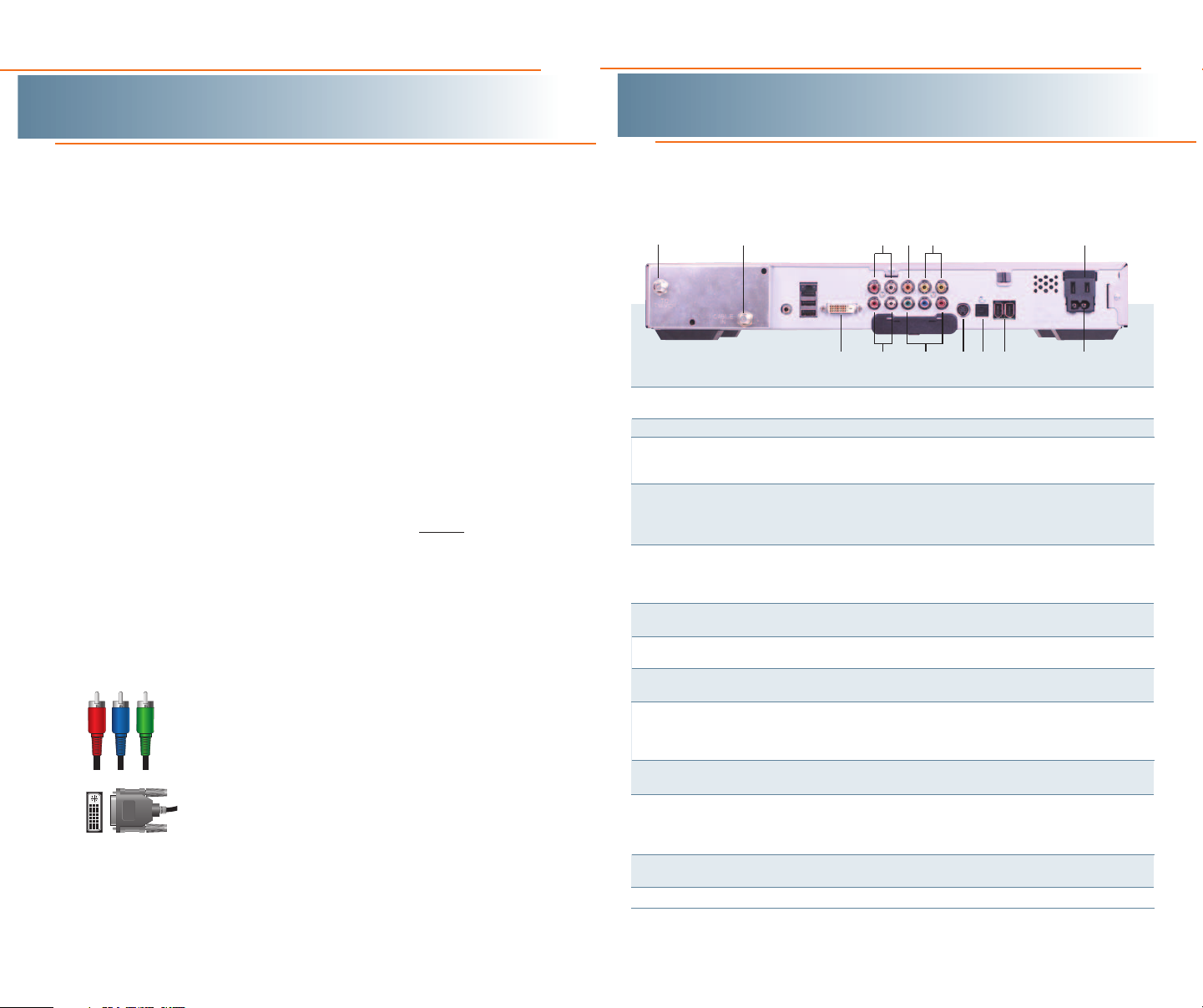
The back panel of the HD digital receiver consists of three types of
interfaces — audio, video and data. The following drawing describes the
most commonly used ports.
1
KEY DESCRIPTION
1 TO TV/VCR This coaxial output connector is used to connect the cable box to
2 CABLE IN The CABLE IN connector connects the HD receiver to the cable wall outlet.
3 AUDIO IN R These connectors are used to connect the digital receiver between a
AUDIO IN L peripheral audio device such as a CD player and a stereo tuner or
4 SPDIF The orange coaxial SPDIF connector is a digital output connection
5 VIDEO IN The VIDEO IN connector accepts an RCA video input from a VCR,
VIDEO OUT camcorder or other video device. (Not currently enabled.) The VIDEO
6 OUTLET This AC outlet may be used to plug your TV into the cable box as a
7 DVI-D Digital Video Interface, connects HD receiver to the HDTV using a DUI
8 AUDIO OUT R The RCA phono-type connectors are used to deliver audio to a
AUDIO OUT L stereo receiver.
9 Y Pb Pr These connectors are used to deliver component video to a HD-ready
10 S-VIDEO This connector is used to deliver high quality, standard definition video
11 OPTICAL
SPDIF
12 IEEE 1394 Firewire Digital Interface to connect high-definition monitor or
13 POWER INLET Connects the digital r
2
a TV or VCR operating on channel 3 or 4.
A/V receiver.
that carries Dolby Digital 5.1 audio or PCM audio. It is used to
connect the digital receiver to a stereo tuner or A/V receiver to
provide surround-sound.
OUT connector is used to deliver RCA video to an external device such
as a VCR or TV.
convenient additional outlet.
cable. (optional)
TV or monitor. Though capable of delivering standard definition video to
your TV or monitor, these cables are necessary to deliver HighDefinition video.
to the external devices that accept S-Video inputs, (optional)
The OPTICAL SPDIF connector is an optical digital output connection that
ries Dolby Digital 5.1 audio or PCM audio. It is used to connect the
car
cable box to a stereo tuner or A/V receiver to provide surround-sound,
theater style audio.
high-definition television. (optional, not available on all models)
4 6
53
81011 13
9
(optional)
eceiver to the power cor
127
MODEL MAY VARY
d.
Charter Business Self-Install Guide 32 charter-business.com
Page 4

U
SB
T
V
P
ass Card
I
R
AUDIO IN
AUDIO
OUT
R
L
RINSPDIF OUT
P
bYPr
L
V
IDEO
C
ABLE
IN
T
O
TV/VCR
S-VIDEO
OPTICAL
SPDIF
CONVENIENCE
OUTLET
SWITCHED
105/125V
6
0Hz
4
A MAX
500W MAX
Y
Pb
Pr
Video 3
Video 2
Cable/
Antenna IN
HDTV
R
L
Video 1
S-Video
Video
Audio
R
L
R
L
R
L
DVI IN
IEEE 1394
Connects to wall
DVI
CABLE
SOLD
SEPARATELY
U
SB
T
V
Pass Card
I
R
AUDIO IN
AUDIO
O
UT
R
L
R
INSPDIF OUT
PbYPr
L
V
IDEO
C
ABLE
IN
TO
TV/VCR
S
-VIDEO
O
PTICAL
SPDIF
C
ONVENIENCE
O
UTLET
SWITCHED
1
05/125V
6
0Hz
4A MAX
500W MAX
Y
Pb
Pr
Video 3
Video 2
Cable/
Antenna IN
HDTV
R
L
Video 1
S-Video
Video
Audio
R
L
R
L
R
L
IEEE 1394
D
VI IN
Connects to wall
Installation Diagrams
Connecting the high-definition digital receiver to
an HDTV using the included cables
This is a common configuration for HDTV’s which uses the component
cables provided by your Charter Business Quick-Start Install kit.
Installation Diagrams
Connecting the high-definition digital receiver to
an HDTV using a DVI cable (DVI cable sold separately)
This is the configuration you will use if you already have a DVI connector for
your HDTV.
What you will need:
What you will need:
1 COAX cable 1 RCA cable 1 Y, Pb, Pr
component
cable
1
3
2
Note: The exact location of
STEP ONE: Connect the coax cable between the cable wall outlet and
the CABLE IN por t on the high-definition digital receiver.
STEP TWO: Locate the Y, Pb, Pr inputs on the HDTV and the Y, Pb, Pr
outputs on the high-definition digital receiver. (Y=green, Pb-blue, Pr-red).
Connect the provided component cable (red, blue green) to the
ports on the high-definition digital receiver and the corresponding
OUT
IN por ts on the HDTV.
STEP THREE: Connect the RCA cables between the DIGITAL AUDIO OUT
R (red)/DIGITAL AUDIO OUT L (white) por ts on the high-definition digital
receiver with the
AUDIO IN R (red)/AUDIO IN L (white) ports on the HDTV.
STEP FOUR: Plug in and turn on your devices. Select the input source on
your HDTV that you used. See page 9 to pr
ogram your picture settings.
the ports on your digital
receiver may vary.
Y, Pb, Pr
1 COAX cable 1 RCA cable 1 DVI cable
2
1
3
Note: The exact location of
the ports on your digital
receiver may vary.
STEP ONE: Connect the coax cable between the cable wall outlet and
the CABLE IN por t on the high-definition digital receiver.
STEP TWO: Connect the DVI cable between the DVI por t on the HD
Receiver and the DVI/HDCP IN port on the HDTV.
STEP THREE: Connect the RCA cables between the DIGITAL AUDIO
(red) / DIGITAL AUDIO OUT L (white) ports on the high definition
OUT R
eceiver with the AUDIO IN R(red
digital r
)
UDIO IN L
/A
on the HDTV.
STEP FOUR: Plug in and tur
n on your devices. Select the DVI input
source on your HDTV. See page 9 to program your picture settings.
Charter Business Self-Install Guide 54 charter-business.com
(white) por
ts
Page 5

R
L
U
SB
T
V
Pass Card
I
R
AUDIO IN
AUDIO
OUT
R
L
RINSPDIF OUT
P
bYPr
L
VIDEO
C
ABLE
I
N
T
O
TV/VCR
S
-VIDEO
OPTICAL
SPDIF
CONVENIENCE
OUTLET
S
WITCHED
105/125V
60Hz
4A MAX
500W MAX
Cable/
Antenna IN
Audio IN
Audio OUT
Video IN
S-Video OUT
Video OUT
Cable/
Antenna OUT
VCR
S-Video IN
Video 3
Video 2
Cable/
Antenna IN
HDTV
R
L
Video 1
L
Audio
L
R
Y
Pb
L
R L
R
R
Pr
D
VI IN
IEEE 1394
Connects to wall
S-Video
Video
Installation Diagrams
Installation Diagrams
Connecting the high-definition digital receiver to
an HDTV and a stereo VCR
This configuration allows you to watch HD and standard-definition video on your
HDTV as well as record and play standard-definition video through your VCR.
What you will need:
1 COAX cable 2 RCA cables 1 Y, Pb, Pr
1
3
2
component
cable
Note: The exact location of
the ports on your digital
receiver may vary.
You may need to turn off your
VCR on for this configuration.
Connecting the high-definition digital receiver to
an HDTV and an DVD player
If you have a DVD player, connect it directly to the HDTV as indicated below.
What you will need:
1 COAX cable 1 RCA cables 1 Y, Pb, Pr
1
Note: The exact location of the ports on your digital receiver may vary.
2
3
component
cable
4
5
STEP ONE: Connect the coax cable between the cable wall outlet and
CABLE IN port on the high-definition digital receiver.
the
STEP TWO: Connect the provided component cable between the Y, Pb,
Pr OUT
receiver and the corresponding
STEP THREE: Connect RCA composite cables (red, white, yellow)
between the
and
the
on the VCR.
STEP FOUR: Repeat Step three using a second set of RCA Cables
between the VCR and HDTV.
STEP FIVE: Plug in and turn on your devices. Select the input source on
your HDTV that corresponds with the por ts that you used on the back of
your HDTV. See page 9 to program your picture settings.
(Y=green, Pb-blue, Pr-red) por ts on the high-definition digital
VIDEO OUT (yellow) ports on the high-definition digital receiver with
DIGITAL AUDIO OUT R (red)/DIGITAL AUDIO OUT L (white)
Y, Pb, Pr IN por ts on the HDTV.
AUDIO IN R (red)/AUDIO IN L (white) and VIDEO IN (yellow) por ts
Steps ONE, TWO, and THREE: See page 4 for instructions on connecting the HDTV
to the high-definition digital receiver. (You will use the coax cable and Y, Pb, Pr
cables for this step).
After connecting your HD digital receiver to your HDTV as demonstrated on
page 4, complete the following steps to connect your DVD player.
STEP ONE: Connect the RCA video cable (yellow) between the VIDEO
OUT por t on the DVD player and a VIDEO IN port on the HDTV.
STEP TWO: Connect the RCA audio cables (red and white) between the
AUDIO OUT L (white) /AUDIO OUT R (red) ports on the DVD player and
the A
UDIO IN L
(white) /A
UDIO IN R (red) por
ts on the HDTV
Note: You might need to select the input ports that you used for this connection
to view DVD content.
Charter Business Self-Install Guide 76 charter-business.com
.
Page 6

USER SETTINGS
TV TYPE 1?:9
YPbPr OUTPUT 1080I
4
:3 OVERRIDE 480i
CLOSED CAPTION DISABLED
OPTIONS:
PEN SIZE
FONT STYLE
FOREGROUND COLOR
FOREGROUND OPACITY
BACKGROUND COLOR
BACKGROUND OPACITY
SERVICE SELECTION
SETTINGS
RESTORE DEFAULTS
AUTO
AUTO
A
UTO
AUTO
AUTO
AUTO
AUTO
AUTO
>
SELECT TV TYPE:
Installation Diagrams
Connecting the high-definition digital receiver to
an HDTV and an A/V receiver
Programming your HD picture settings
To get the best possible audio performance out of your HD ser vice, use an A/V
receiver for sound production. Follow the cabling instructions below.
What you will need:
1 COAX cable 1 RCA cables 1 Y, Pb, Pr
component
cable
1
3
2
Note: The exact location of
the ports on your digital
receiver may vary.
STEP ONE: Connect the coax cable between the cable wall outlet and
the
CABLE IN port on the high-definition digital receiver.
STEP TWO: Connect the provided component cable to the Y, Pb, Pr OUT
ports (Y=green, Pb-blue, Pr-red) on the high-definition digital receiver and
the corresponding
IN por ts on the HDTV.
STEP THREE: Connect RCA composite cables between the DIGITAL
AUDIO OUT R (red)/DIGITAL AUDIO OUT L (white) por ts on the high-
definition digital receiver with the
AUDIO IN R (red)/AUDIO IN L (white)
ports on the A/V Stereo Receiver.
STEP FOUR: Plug in and tur
selected the correct source inputs for each device. See page 9 to
program your picture settings.
n on your devices. Confir
m that you have
The final step is tailoring your digital receiver to the capabilities of your HDTV using
the On Screen Menu. This allows the digital receiver to automatically optimize both
Standard and High-Definition video, based on your HDTV and personal preferences.
To access the On Screen Menu, power
ON your HDTV and power OFF the digital
receiver. Press the MENU button on either
The settings shown in this diagram are for
illustrative purposes, and only represent one
possible configuration. Please refer to the
following sections for more setting options.
your remote control or the digital receiver
front panel to call up the On Screen
Display.* You may use either the digital
receiver front panel or the remote control
to navigate the display:
•
The arrow on the left indicates the
position of the cursor.
•
Press the and
buttons to select the
setting you
wish to change.
•
Press the button to select an option for that setting.
•
To exit the setting and move to another setting, use
the and buttons.
•
Press the POWER or MENU button to exit the menu and
save your settings.
TV TYPE
The first user setting is TV TYPE.
Your selection tells the
digital receiver
what type of TV you have and how
you prefer to watch widescreen
programming. Your choices are 16:9,
4:3 Letterbox, or 4:3 Pan Scan.
•
Choose 16:9 if you have a
widescreen HDTV.
•
Choose 4:3 Letterbox if you have a
standard TV and you prefer to watch widescreen programming
in its original aspect ratio.
If the On Scr
*
een Menu does not appear on your HDTV scr
support the default, standard definition setting (480i). In this case, use the digital
eceiver fr
r
ont panel LED to view and change your settings.
een, your TV may not
Charter Business Self-Install Guide 98 charter-business.com
Page 7

Troubleshooting
Programming your HD picture settings
•
Choose 4:3 Pan Scan if you have a
standard screen TV and you prefer
that widescreen programming is
cropped to fill your screen. Think of
this last choice as watching a
theater-style movie that has been
reformatted to fit your standard
screen TV.
Y Pb Pr OUTPUT
Next, use the down arrow to select Y Pb Pr OUTPUT. This setting indicates
the picture resolution you prefer when watching High-Definition programming.
The choices, listed in order of highest to lowest picture resolution, are
1080i, 720p, 480p, and 480i. Your selection will depend on which format(s)
your HDTV supports. To maximize your high-definition viewing experience,
refer to your television set owner's manual, and use the right arrow button to
choose the setting that indicates the highest picture resolution that your
television will support.
4:3 OVERRIDE
Finally, use the down button arrow to select 4:3 OVERRIDE. By selecting 480i
or 480p you are telling the
programming to your TV in its original broadcast format. Select OFF and the
cable box
above. To exit and save changes press the POWER or MENU button.
For more details on configuring your
setting Closed Caption preferences, see the User Guide for your HD receiver
which is available at
will default to the resolution selected in the Y Pb Pr OUTPUT setting
digital receiver
http://charter.com/quickstart.
to send Standard Definition
digital receiver
output settings, including
Problem
Possible Solution
No sound
• Press MUTE on the remote control to restore the volume level.
• Check that the receiver is set to the proper input source.
• Turn your VCR on.
No picture
• Check to be sure that all cables are connected properly and that your
TV is tuned to channel 3 or 4, if using the TO TV-VCR
connections. Hand-tighten the cable connections if necessary.
• Check that your component connection cables are not crossed.
Y goes to Y, Pb to Pb and Pr to Pr.
• If connected through the RCA video connection, make sure the cables
are connected properly.
• Turn VCR on/off.
• Ensure that the proper video display format for your TV has been selected.
No Guide or wrong Guide
• Check that your HD receiver is connected directly to the cable wall outlet.
Picture or sound is noisy on one channel
• Reconnect the coax cables and hand-tighten if loose.
Sound from only one stereo speaker
• Hand-tighten or reconnect the cables.
• Ensure that wires are not frayed and plugs are not bent or broken.
No power
• Reconnect the power cord.
• Ensure that the HD receiver is plugged into an active outlet.
Remote control does not work
• Press CABLE on the remote control.
• Ensure that nothing is blocking a clear line of sight between the HD
receiver and the remote control.
• Change the batteries in your remote control and then re-program
emote contr
your r
Poor audio quality
• Use the remote control to set the HD receiver volume
level to approximately 3/4 of maximum volume level and then adjust
the audio levels on the external devices.
ol.
Charter Business Self-Install Guide 1110 charter-business.com
Page 8

Notes
12 charter-business.com
Char
ter Business
Self-Install Guide
 Loading...