

Page 1
User Guide
DCT2500
Digital Cable
Receiver
Q
MOTOROLA
intelligence everywhere"
Page 2
Graphical symbols and supplemental warning marking locations on bottom of terminal.
REPAIRS
If you find the unit in need of repair, contact your cable system operator for repair or
replacement.
NOTE TO CATV SYSTEM INSTALLER
This reminder is provided to call the CATV system installer’s attention to Article 820-40 of
the NEC that provides guidelines for proper grounding and, in particular, specifies that the
cable ground shall be connected to the grounding system of the building, as close as
possible to the point of cable entry as practical.
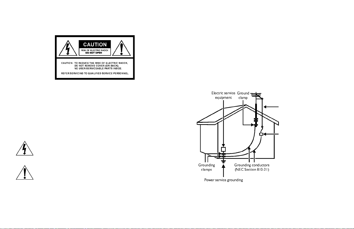
EXAMPLE OF ANTENNA GROUNDING
WARNING
TO PREVENT FIRE OR SHOCK HAZARD, DO NOT EXPOSE THIS APPLIANCE TO
RAIN OR MOISTURE.
CAUTION
TO PREVENT ELECTRICAL SHOCK, DO NOT USE THIS (POLARIZED) PLUG
WITH AN EXTENSION CORD, RECEPTACLE, OR OTHER OUTLET UNLESS
THE BLADES CAN BE FULLY INSERTED TO PREVENT BLADE EXPOSURE.
The lightning flash with arrowhead symbol, within an equilateral triangle, is
intended to alert the user to the presence of uninsulated “dangerous voltage”
within the product’s enclosure that may be of sufficient magnitude to constitute
a risk of electric shock to persons.
The exclamation point, within an equilateral triangle, is intended to alert the
user to the presence of important operating and maintenance (servicing)
instructions in the literature accompanying the appliance.
This installation should be made by a qualified service person and should conform to all
local codes.
electrode system
(NEC Article 250, Part H)
NEC=NATIONAL ELECTRICAL CODE
Antenna lead
in wire
Antenna
discharge unit
(NEC Section 810-20)
Page 3

Important Safety Instructions
N Read instructions
All the safety and operating instructions should
be read before the appliance is operated.
O Retain instructions
The safety and operating instructions should be
retained for future reference.
3 Heed warnings
All warnings on the appliance and in the
operating instructions should be adhered to.
4 Follow instructions
All operating and use instructions should be
followed.
5 Cleaning
Unplug this product from the wall outlet before
cleaning. Do not use liquid cleaners or aerosol
cleaners. Use a damp cloth for cleaning.
S Attachments
Do not use attachments not recommended
as they may cause hazard.
T Water and moisture
Do not use this equipment near water; for
example, near a bath tub, wash bowl, kitchen
sink, or laundry tub, in a wet basement, or near
a swimming pool, and the like.
8 Accessories
V Ventilation
10 Power sources
Do not place this product on an unstable cart,
stand, tripod, bracket, or table. The product may
fall causing serious injury and serious damage to
the appliance. Use only with a cart, stand, tripod,
bracket, or table recommended by the
manufacturer, or sold with the equipment. Any
mounting of the appliance should follow the
manufacturer’s instructions, and should use a
mounting accessory recommended by the
manufacturer.
Slots and openings in the cabinet are provided for
ventilation and to ensure reliable operation of the
equipment and to protect it from overheating. The
openings should never be blocked by placing the
product on a bed, sofa, rug, or similar surface.
Equipment should never be placed near or over a
radiator or heat register, or in a built-in installation
such as a bookcase or rack unless proper
ventilation is provided.
This product should be operated only from the
type of power sources indicated on the marking
label. If you are not sure of the type of power
supplied to your home, consult your local power
company. For equipment intended to operate from
battery power, or other sources, refer to the
operating instructions.
11 Ground or polarization
This equipment may be equipped with a polarized
alternating-current line plug (a plug having one
blade wider than the other). This plug will fit into
the power outlet only one way. This is a safety
feature. If you are unable to insert the plug fully
into the outlet, try reversing the plug. If the plug
should still fail to fit, contact your electrician to
replace your obsolete outlet. Do not defeat the
safety purpose of the polarized plug.
12 Alternate warnings
This equipment may be equipped with a 3-wire
grounding-type plug, a plug having a third
(grounding) pin. This pin will only fit into a
grounding-type power outlet. This is a safety
feature. If you are unable to insert the plug into
the outlet, contact your electrician to replace your
obsolete outlet. Do not defeat the safety purpose
of the grounding-type plug.
13 Power cord protection
Power supply cords should be routed so that they
are not likely to be walked on or pinched by items
placed upon or against them, paying particular
attention to cords at plugs, convenience
receptacles, and the point where they exit from
the appliance.
1 4 Outdoor Antenna Grounding
If an outside antenna or cable system is connected
to the equipment, be sure the antenna or cable
system is grounded as to provide some protection
against voltage surges and built-up static charges.
Page 4

N R Lightning
For added protection for this equipment during
a lightning storm, or when it is left unattended
and unused for long periods of time, unplug it
from the wall outlet and disconnect the antenna
or cable system. This will prevent damage to
the video product due to lightning and power
line surges.
16 Power lines
An outside antenna system should not be
located in the vicinity of overhead power lines
or where it can fall into such power lines or
circuits. When installing an outside antenna
system, extreme care should be taken to keep
from touching such power lines or circuits, as
contact with them may be fatal.
17 Overloading
Do not overload wall outlets and extension
cords as this can result in a risk of fire or
electrical shock.
18 Object and liquid entry
Never push objects of any kind into this
equipment through openings as they may touch
dangerous voltage points or short-out parts that
could result in a fire or electrical shock. Never
spill liquid of any kind on the product.
1V Servicing
Do not attempt to service this equipment
yourself as opening or removing covers may
expose you to dangerous voltage or other
hazards, refer all servicing to qualified
service personnel.
20 Damage requiring service
Unplug this equipment from the wall outlet and
refer servicing to qualified service personnel under
the following conditions:
3l When the power supply cord or plug is
damaged.
b> If the equipment has been exposed to rain
or water.
C If liquid has been spilled, or objects have fallen
into the equipment.
d If the equipment does not operate normally by
following the operating instructions. Adjust
only those controls that are covered by the
operating instructions as an improper
adjustment of other controls may result in
damage and will often require extensive work
by a qualified technician to restore the
equipment to its normal operation.
G If the equipment has been dropped or cabinet
has been damaged.
1“ When the equipment exhibits a distinct change
in performance, indicating a need for service.
21 Replacement parts
When replacement parts are required, be sure the
service technician has used replacement parts
specified by the manufacturer or have the same
characteristics as the original part. Unauthorized
substitutions may result in fire, electric shock, or
other hazards.
22 Safety check
Upon completion of any service or repairs to this
video product, ask the service technician to
perform safety checks to determine that the
product is in proper operational condition.
2P Heat
The product should be situated away from heat
sources such as radiators, heat registers, stoves, or
other products (including amplifiers) that produce
heat.
24 Battery usage
Notwithstanding any information provided by
Motorola in this manual regarding the use of
batteries, the end user assumes all responsibility
and liability to use and dispose of batteries in
accordance with all applicable laws, rules and
regulations. Motorola will not be liable to anyone
for the end user's failure to use and/or dispose of
batteries in the proper manner and in accordance
with such laws, rules and regulations, or for any
defect contained in batteries that may cause injury
damage to persons or property.
Page 5

OR Telephone equipment
Observe the following precautions when installing
telephone modem equipment:
3i Never install telephone wiring during a lightning
storm.
b> Never install telephone jacks in a wet location
unless the jack is specifically designed for wet
locations.
C Never touch uninsulated telephone wires or
terminals unless the telephone lines have been
disconnected at the network interface.
dl Use caution when installing or modifying
telephone lines.
Page 6

Regulatory Information
Federal Communications Commission Radio and Television Interface Statement for a
Class ‘B’ Device
This equipment has been tested and found to comply with the limits for a Class B digital
device, pursuant to part 15 of the FCC Rules. These limits are designed to provide
reasonable protection against harmful interference in the residential installation. This
equipment generates, uses and can radiate radio frequency energy and, if not installed and
used in accordance with the instructions, may cause harmful interference to radio
communications. However, there is no guarantee that interference will not occur in a
particular installation.
If the equipment does cause harmful interference to radio or television reception, which can
be determined by turning the equipment off and on, the user is encouraged to try to correct
the interference by one of the following measures:
• Increase the separation between the equipment and the affected receiver
• Connect the equipment on a circuit different from the one the receiver is on
• Ensure that the cover plate for the security card is secured and tight
Changes or modification not expressly approved by the party responsible for compliance
could void the user’s authority to operate the equipment.
Copyright © 2003 by Motorola, Inc. All rights reserved. No part of the contents of this book may be reproduced or transmitted in any form or by any means without written permission of
the publisher.
MOTOROLA and the Stylized M Logo are registered in the US Patent & Trademark Office. Manufactured under license from Dolby Laboratories. "Dolby" and the double-D symbol are
registered trademarks of Dolby Laboratories. All other product or service names are the property of their respective owners.
Motorola reserves the right to revise this publication and to make changes in content from time to time without obligation on the part of Motorola to provide notification of such revision
or change. Motorola provides this guide without warranty of any kind, either implied or expressed, including, but not limited to, the implied warranties of merchantability and fitness for a
particular purpose. Motorola may make improvements or changes in the product(s) described in this manual at any time.
Declaration of Conformity
According to 47 CFR, Parts O and 15 for Class B Personal Computers and Peripherals;
and/or CPU Boards and Power Supplies used with Class B Personal Computers,
Motorola, Inc., 6450 Sequence Drive, San Diego, CA 92121, 1-800-225-9446, declares
under sole responsibility that the product identifies with 47 CFR Part 2 and 15 of the
FCC Rules as a Class B digital device. Each product marketed is identical to the
representative unit tested and founded to be compliant with the standards. Records
maintained continue to reflect the equipment being produced can be expected to be
within the variation accepted, due to quantity production and testing on a statistical
basis as required by 47 CFR 2.909. Operation is subject to the following condition: This
device must accept any interference received, including interference that may cause
undesired operation. The above named party is responsible for ensuring that the
equipment complies with the standards of 47 CFR, Paragraphs 15.107 to 15.109.
Canadian Compliance
This Class B digital apparatus meets all requirements of the Canadian
Interference-Causing Equipment Regulations. Cet appareil numérique de la classe B
respects toutes les exigences du Règlement sur le matériel brouilleur du Canada.
Page 7

CONTENT
Introduction
Front Panel
Rear Panel................................................................6
Rear Panel Options...................................................9
Recording Your Connections
Using the Remote Control
Installing Batteries
Basic Operation
Turning Power On and Off
Changing Channels................................................17
Adjusting the Volume.............................................17
Electronic Program Guide.......................................18
Audio Output Modes
.....................................................
..............................................................
......................
............................
.................................................
.............................................
.....................................
..............................................
11
12
16
17
17
18
2
3
Audio/Video Connections
Connecting your DCT2500
Standard TV Cabling
Standard VCR Cabling............................................21
Cabling with RF Bypass
Composite Baseband and S-Video
Composite VCR Cabling
Stereo Cabling Diagram (VCR to Stereo)
Stereo Cabling Diagram (TV to Stereo)
Baseband Cabling Diagram
Dolby Digital Cabling Diagram
Troubleshooting
............................................
.............................
...........................
..............................................
..........................................
.........................
.........................................
.................
...................
....................................
...............................
19
20
20
22
23
24
25
26
27
28
29
Page 8

INTRODUCTION
Your DCT2500 includes one or more of the
following features:
Remote control
Volume control
Parental control
Favorite channel recall
Easy Pay-Per-View purchases
Electronic program guide
Video on Demand
Digital audio
Congratulations on receiving your state-of-the-art DCT2500 digital consumer
terminal. The DCT2500 brings unsurpassed digital audio and video quality to
your TV viewing. Electronic program guide (EPG) menus provide convenient
control of selecting and viewing programs. It’s simple to set up and easy to
operate.
You can purchase Pay-Per-View special events, recent movies or Video on
Demand. Video on Demand is similar to renting a video, including the ability
to pause, rewind, and fast-forward.
This guide introduces you to the features and operation of the DCT2500.
Access to the DCT2500 features is gained through the EPG.
To get the most out of your DCT2500, be sure to read your EPG
instruction manual.
1
Page 9
INTRODUCTION
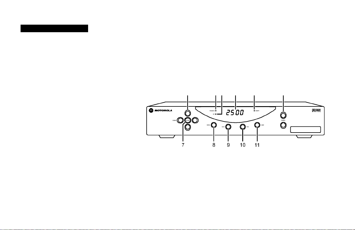
Front Panel
The DCT2500 front panel has II keys and an LED display. Use the keys to
perform basic functions such as changing channels and powering on and off.
Display the current channel or time of day on the LED by changing the
default settings in the electronic program guide.
1 2 3
5 6
3
Page 10

■introduction
Item Description
1
-■0^30
2
3
4
5
6
T
CD UU
-■©i£30
©
Moves the cursor in menus and electronic program guide (EPG) screens
0
MESSAGED O
O
pc nn
0 REMOTE Flashes when a signal is received from the remote control
0
CHANNEL
Lights to indicate that a message is present
Lights when the unit is turned on
Displays current channel number or time of day
Changes the channel up and down
0
©
©
Selects menu options, Pay-Per-View (PPV) events, and tunes channels from the EPG
4
Page 11

■introduction
Item Description
8
9
io
11
POWER
""^Q)
(Q)““
Q)
Turns the DCT2500 on and off
Displays the main menu
Displays current channel and program information
Displays the EPG
R
Page 12
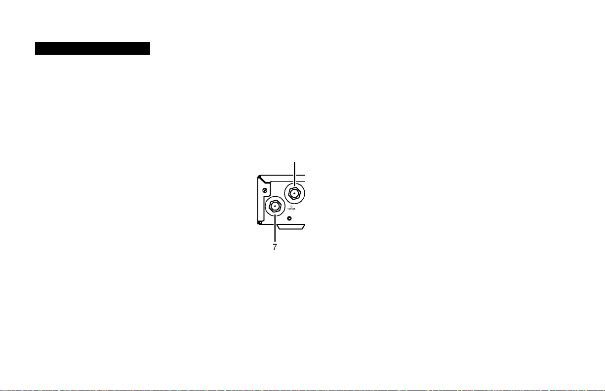
INTRODUCTION
Rear Panel
Before you begin installing the DCT2500, take a moment to become familiar
with the rear panel connections. These connectors are for system cabling.
An AC power cord connects the DCT2500 to an electrical power outlet.
For cabling diagrams, see Connecting Your DCT2500.
1 2 3
' r
audiho
VIDEO DIGITAL
-Gdf}
9 10 11 12 13 14 15
6
I TVPASSCARD
16
S!;SE”
60Hz
4A MAX
500W MAX
6
Bl n
IKSE2IB
Page 13

■introduction
Item Description
1
2
3
4
5
6
T
8
V
10
RF IN
TO RF IN
AUDIO OUT
TO TV R L
AUDIO OUT
TO VCR R L
DATA
AC power
TO TV/VCR
CABLE IN
S-VIDEO
VIDEO
A coaxial input that is connected to the TO RF IN, see Connecting the DCT2500.
A coaxial input that directs the cable signal to other connections on the DCT2500.
Right/left RCA stereo outputs connect the DCT2500 to your TV. The audio output to your TV is volume
controlled.
Right/left RCA stereo outputs connect the DCT2500 to your VCR. The audio output to your VCR is line level.
A high-speed serial interface for connecting an external high definition TV decoder (do not connect your PC to
this interface).
This is a two-plug AC power inlet. The bottom plug is for attaching a power cord. The top plug can be
configured for plugging in another device such as a TV or VCR.
A coaxial output to connect the DCT2500 to the TV or VCR.
A coaxial input for the incoming signal from the wall outlet.
An S-Video connector for sending high quality video to external devices (high-end VCR or TV) that accept
S-Video. (Optional)
This RCA video output connects the DCT2500 to an input on a TV, VCR, or other device.
T
Page 14

■introduction
Item Description
DIGITAL AUDIO
11
A coaxial audio output to connect the DCT2500 to a digital A/V receiver.
COAX
DIGITAL AUDIO
12
A Toslink connector to connect the DCT2500 to a digital A/V receiver. (Optional)
OPTICAL
TV Pass Card slot
13
USB The Universal Serial Bus (USB) is used to connect to devices such as keyboards, joysticks, scanners, disk storage,
14
IR
15
PHONE
16
This space is reserved for future use.
PCs, printers, and digital cameras, if supported. (Optional)
A stereo mini-phone connector connecting the optional Infrared (IR) Blaster attachment for your DCT2500.
For use in Telco return systems. See “Rear Panel Options” for more information. (Optional)
8
Page 15

INTRODUCTION
3
Switch
options
Rear Panel Options
The following rear panel options can be included on your DCT2500:
Item Description
A/B Switch This contains coaxial input connectors used
1
RF Bypass
2
DUAL A/B-RF BYPASS These coaxial connectors are used in a dual
3
Telco Return
4
in a dual cable system and with an A/B box.
These coaxial connectors enable the cable
signal to bypass the DCT2500 and go
directly to a cable-ready TV or VCR.
cable system. The cable signal from A or B
goes directly to a cable-ready TV or VCR.
The Telco Return Impulse Pay-Per-View
option is a telephone connection module
that enables you to purchase special
programming on one-way cable systems.
PHONE
rnnn
4
Telco
return
9
Page 16

INTRODUCTION
USB
5
S-VDEO
6
DIGITAL
AUDIO
OPTICAL
®
7
Item Description
R
USB The Universal Serial Bus (USB) is used to
support devices such as keyboards, joysticks,
scanners, disk storage, PCs, printers, and
digital cameras, if supported.
S-Video
6
Toslink
7
The S-Video connector sends high quality
video to external devices (high-end VCR or
TV) that accept S-Video.
The Toslink connector is used to connect
the DCT2500 to a digital A/V receiver.
io
Page 17

RECORDING YOUR CONNECTIONS
A/B In
® ;©
■©
-|=
Switch
options
Home
Theater
Receiver
VCR
TV
RF Bypass RF Bypass
Dual A/B
© g-©
©
tbkK«
^ ^“0- -©~" ® ©Ij
MONITOR
OUT IN
S-VIDEO VIDEO
© ©
CABLE IN
CABLE OUT
©
CABLE IN
SWTCN3J
^ ^ V® S@
IN ^ íQ vQ s©
OUT R ® ^ V® s©
AUDIO © ® © ©
IN R L VIDEO S-VIDEO
AUDIO
OUT
^AUDIO,.,
© IN ©
0
AUDIO ^
©OUT®
IN IN
® © ® ©
R L VIDEO S-VIDEO
© ©
VIDEO IN S-VIDEO IN
© ©
VIDEO OUT S-VIDEOOUT
OUT OUT
COAXIAL
®
□
OPTICAL
Use this diagram to record cable connections from the rear panel. Later you
can use this diagram to reconnect your system if you move the equipment,
or add new equipment.
Your home entertainment equipment may not have all connectors shown in
the illustration or may have connectors that are not shown here.
Disconnect the power from the DCT2500 before connecting or changing cable
connections. Do not place another component or object on top of the DCT2500.
11
Page 18

USING THE REMOTE CONTROL
1
15
16
17
18
19
■20
■21
Use the remote control to operate the DCT2500, TV, and VCR.
Your remote control may be different from the one illustrated here. The remote
control must be programmed for use. If your service provider has not programmed
your remote control, refer to the remote control instruction guide supplied by your
service provider.
■22
12
Page 19

■using the remote control
Key
1
2
3
4
5
6
T
8
Item Description
AUDIO, VCR, CABLE, or
Selects the desired device to control (the selected mode remains active until you press another key)
TV
HELP
POWER
PAGE ▲ or PAGET
Displays the help screen
Turns the selected home entertainment component on or off
Pages through menu screens and electronic program guide (EPG)
EXIT Exits menus and EPG
Moves cursor around the EPG and menu screens
OK/SELECT
GUIDE
Selects menu options and Pay-Per-View events, or tunes programs from the EPG (your remote
control may only have OK; it performs the same functions)
Displays the EPG
13
Page 20

■using the remote control
Key
V
Item Description
VOLUME + or
VOLUME 10
11
12
A, B, or C
NUMBER KEYS
TV/VCR
BYPASS
13
◄ DAY
DAY ►
14 STOP, PAUSE, PLAY,
REW, RECORD, F.FWD
15
16
MUTE
LOCK/PPV
Increases or decreases volume of the currently selected device
Functionality is determined by your service provider
Directly selects a channel
When in CABLE mode, enables OF Bypass, if available. Bypass is optional.
Use when operating the electronic program guide (moves EPG ahead or back 24 hours)
Controls the VCR
Toggles the sound on and off
Limits viewing of selected programs, and accesses the Pay-Per-View menu (your remote control may
only have lock; this key performs the same functions)
14
Page 21

■using the remote control
Key
17 INFO
18 MENU
19 LAST
20 CHANNEL + or
Item Description
Displays the current channel and program information (not supported by all applications)
Displays the Main menu
Recalls the last channel or goes back one screen in the menu
Changes the channels up or down
CHANNEL 21 FAVORITE
Displays preset favorite cable channels
22 ENTER/MUSIC Displays digital music channel menus (on some TV models, press to enter channels)
15
Page 22

USING THE REMOTE CONTROL
Installing Batteries
Before you can use the remote control, you must install two AA (1.5-volt)
alkaline batteries:
N Slide open the battery door on the back of the remote control.
2 Insert the batteries in the direction indicated on the inside of the
battery compartment.
Batteries installed incorrectly can cause battery leakage and corrosion that
will damage the remote control.
3 Slide the battery door closed until it snaps into place.
Point the remote control at the DCT2500, press CABLE, and then press
POWER. If the DCT2500 does not turn on, check the orientation of the
batteries or replace with new batteries.
Your remote control may be different from the one illustrated here. Refer to the
remote control instruction guide for details on battery installation.
16
Page 23

BASIC OPERATION
Turning Power On and Off
Press POWER on the front panel to turn the DCT2500 on or off. If using the
remote control, be sure it is in cable mode by pressing CABLE, and then press
POWER.
Changing Channels
You can change channels in two ways:
• Press CHANNEL ▲ or ▼ on the front panel of the DCT2500, or
press CHANNEL + or - on the remote control to step through the
channel selection.
• Enter the number of the channel you want to tune using the numeric
keys on the remote control.
Adjusting the Volume
Press VOLUME + or - on the remote control to adjust the volume. When
you adjust the volume, the volume scale is displayed on the screen.
Press MUTE on the remote control to turn the sound off and on again.
For best audio quality, use the remote control to set the DCT2500 to
approximately % of the maximum volume level and then adjust the audio
levels on the external devices, such as your TV.
Your VCR’s audio outputs are not affected by adjustments to the volume.
17
Page 24

BASIC OPERATION
Electronic Program Guide
The electronic program guide (EPG) displays information about TV programs
and enables you to access features such as Parental Control or
Pay-Per-View. EPGs can vary in look and feel with each service provider.
Reference the EPG instruction manual for detailed instructions.
Audio Output Modes
The DCT2500 includes utilities that enable you to select and adjust its
DIGITAL AUDIO (coaxial or optical) or AUDIO OUT (RCA style) outputs. If your
EPG takes advantage of these utilities, it provides menu choices to select and
optimize the audio output and compression modes. For more information
about audio output mode configuration, refer to your EPG user manual.
18
Page 25

AUDIO/VIDEO CONNECTIONS
Before you begin to hookup your DCT2500, review the following:
NOTE
It is important to remember not to place anything
on top of the DCT2500 and to provide for
adequate ventilation to prevent overheating.
• For basic cable connections, use 75-ohm coaxial cables equipped with
F-type connectors. You can find coaxial cables in your local electronics
store.
• For audio or video outputs, use cables equipped with RCA-type
connectors.
• For the digital audio optical output, use a Toslink cable.
• Disconnect power from the DCT2500 before connecting or changing
cable connections.
• Do not place anything on top of the DCT2500, especially other home
video components.
19
Page 26

CONNECTING YOUR DCT2S00
Standard TV Cabling
Use 75-ohm coaxial cables to connect your DCT2500 to a TV. This is the
most common cable connection, and it provides all of the basic features of
the DCT2500.
If you are using a diagram that connects the coaxial TO TV/VCR connector on
the DCT2500 to the coaxial CABLE IN connector on the TV, you must tune
your TV to channel 3 or 4.
The illustrated connections will not provide stereo audio. Connect the DCT2500 to
the TV using standard RCA audio cables (left and right) to receive stereo audio on
all channels, when available.
20
Page 27

CONNECTING YOUR DCT2S00
©
CABLE IN
©
©
CABLE IN
AUDIO O O O 0
IN R L VIDEO S-VIDEO
AUDIO 0 0 0 ©
OUT R L VIDEO S-VIDEO
AUDIO
0 IN 0
©OUT®
IN IN
OUT OUT
o o
VIDEO IN S-VIDEO IN
o
VIDEO OUT
S-VIDEO OUT
VCR
©
TV
Standard VCR Cabling
To connect your VCR, you will need 75-ohm coaxial cables. The illustrated
VCR connection enables you to record the program you are watching,
including Pay-Per-View events. You can also view videotapes just as you
do now.
The illustrated connections will not provide stereo audio. Connect the DCT2500 to
the TV using standard RCA audio cables (left and right) to receive stereo audio on
all channels, when available.
21
Page 28

CONNECTING YOUR DCT2S00
Cabling with RF Bypass
This cabling diagram illustrates the RF Bypass module installed on the
DCT2500. The RF Bypass enables you to view an unscrambled analog
channel on a TV while recording another channel through the DCT2500.
22
Page 29

CONNECTING YOUR DCT2S00
Composite Baseband and S-Video
Connecting the DCT2500 using the RCA-type baseband outputs enables you
to experience stereo audio when available.
When connecting the video path, never connect baseband composite video and
S-Video at the same time. Because some entertainment equipment will not support
both video inputs simultaneously, use only one connection path.
23
Page 30

CONNECTING YOUR DCT2S00
Composite VCR Cabling
This diagram illustrates how to connect the DCT2500 to a VCR using the
audio connectors on the VCR.
When connecting the video path, never connect baseband composite video
and S-Video at the same time. Because some entertainment equipment will
not support both video inputs simultaneously, use only one connection path.
24
Page 31

CONNECTING YOUR DCT2S00
Stereo Cabling Diagram (VCR to Stereo)
This diagram illustrates how to connect the DCT2500 to a stereo using the
audio connectors on the VCR. The VCR sound is played through the stereo.
When connecting the video path, never connect baseband composite video and
S-Video at the same time. Because some entertainment equipment will not support
both video inputs simultaneously, use only one connection path.
25
Page 32

CONNECTING YOUR DCT2S00
Stereo Cabling Diagram (TV to Stereo)
This configuration provides for the TV sound to play through the stereo.
When connecting the video path, never connect baseband composite video and
S-Video at the same time. Because some entertainment equipment will not support
both video inputs simultaneously, use only one connection path.
26
Page 33

CONNECTING YOUR DCT2S00
In this illustration the baseband connectors on the entertainment components
are labeled o for right audio, i for left audio, V for video, and S for S-video.
Baseband Cabling Diagram
This diagram illustrates audio and video connections to a Dolb/" Digital
receiver. This configuration enables you to record on the VCR and playback
with sound through the Dolby Digital receiver.
To playback Dolby Digital 5.1 sound through the Dolby Digital receiver, you must
connect the DCT2500 to the receiver using the DIGITAL AUDIO COAX or DIGITAL AUDIO
OPTICAL connections. The audio o and L connectors do not carry Dolby Digital 5.1. See
the Dolby Digital Cabling Diagram for more information.
27
Page 34

CONNECTING YOUR DCT2S00
DCT1S00 In this illustration the baseband connectors on the entertainment components
are labeled o for right audio, i for left audio, V for video, and S for S-video.
Dolby Digital Cabling Diagram
This diagram illustrates audio and video connections to a Dolby Digital
-Either/or receiver. This configuration enables you to record on the VCR and playback
with sound through the Dolby Digital receiver.
To playback Dolby Digital 5.1 sound through the Dolby Digital receiver, you must
connect the DCT2500 to the receiver using the DIGITAL AUDIO COAX or DIGITAL AUDIO
OPTICAL connections. The audio o and L connectors do not carry Dolby Digital 5.1.
28
Page 35

TROUBLESHOOTING
Before calling your service provider, review the troubleshooting guide. This information is to help you quickly solve a problem. If
your problem still exists, contact your service provider.
Problem
No sound
No picture
Picture or sound is noisy on one channel
Sound from only one stereo speaker
Possible Solution
Press MUTE on the remote control to restore the volume level.
Check that the stereo is set to the proper input source.
Turn your VCR on.
Make sure the TV or stereo volume is set to an appropriate level. For best audio level
control, use the remote control to set the DCT2500 to approximately % of the
maximum volume level and then adjust the audio levels of the external devices.
Check to be sure that all cables are connected properly (hand-tighten if necessary).
If connected through the baseband RCA video connection, make sure the cables are
connected properly.
If you are watching TV using your VCR, be sure your VCR is on.
Reconnect the cable and hand-tighten if loose.
Hand-tighten or reconnect the cables properly. Be sure wires are not frayed and plugs
are not bent or broken.
29
Page 36

TROUBLESHOOTING
Problem
No power
Remote control does not work
Possible Solution
Reconnect the power cord. Be sure the DCT2500 is plugged into an outlet that is always
live.
Press CABLE on the remote control to ensure the remote control is in cable mode.
Change the batteries in your remote control according to the instructions in the section,
“Installing Batteries.”
Be sure that nothing is on the DCT2500 or blocking a clear line of sight between it and
the remote control.
30
Page 37

Visit our website at:
www.motorola.com
Q
504991-001
05-03
MGBI
MOTOROLA,
 Loading...