

Page 1

DCT 2000
Digital Consumer Terminal
Installation Manual
CURSOR
MESSAGES
REMOTE
A/B
INFO
MENU
SELECT
POWER
A/B
CHANNEL
POWERGUIDE
Page 2
Graphical symbols and supplement warning marking locations on the bottom of the appliance.
This symbol indicates that dangerous voltage levels are present within the equipment. These voltages are not insulated and
may be of sufficient strength to cause serious bodily injury when touched. The symbol may also appear on schematics.
This symbol calls attention to a critical procedure, or means refer to the instruction manual for opening or service
information. Only qualified service personnel are to install or service the equipment. The symbol may also appear in text and
on schematics.
WARNING:
WARNING:
WARNING:WARNING:
TO PREVENT FIRE OR SHOCK HAZARD, DO NOT EXPOSE THIS APPLIANCE TO RAIN OR MOISTURE.
TO PREVENT FIRE OR SHOCK HAZARD, DO NOT EXPOSE THIS APPLIANCE TO RAIN OR MOISTURE.
TO PREVENT FIRE OR SHOCK HAZARD, DO NOT EXPOSE THIS APPLIANCE TO RAIN OR MOISTURE.TO PREVENT FIRE OR SHOCK HAZARD, DO NOT EXPOSE THIS APPLIANCE TO RAIN OR MOISTURE.
CAUTION:
CAUTION:
CAUTION:CAUTION:
TO PREVENT ELECTRICAL SHOCK, DO NOT USE THIS PLUG WITH AN EXTENSION CORD, RECEPTACLE, OR OTHER OUTLET UNLESS THE BLADES
TO PREVENT ELECTRICAL SHOCK, DO NOT USE THIS PLUG WITH AN EXTENSION CORD, RECEPTACLE, OR OTHER OUTLET UNLESS THE BLADES
TO PREVENT ELECTRICAL SHOCK, DO NOT USE THIS PLUG WITH AN EXTENSION CORD, RECEPTACLE, OR OTHER OUTLET UNLESS THE BLADESTO PREVENT ELECTRICAL SHOCK, DO NOT USE THIS PLUG WITH AN EXTENSION CORD, RECEPTACLE, OR OTHER OUTLET UNLESS THE BLADES
CAN BE FULLY INSERTED TO PREVENT BLADE EXPOSURE.
CAN BE FULLY INSERTED TO PREVENT BLADE EXPOSURE.
CAN BE FULLY INSERTED TO PREVENT BLADE EXPOSURE.CAN BE FULLY INSERTED TO PREVENT BLADE EXPOSURE.
FCC Compliance:
FCC Compliance: This equipment has been tested and found to comply with the limits for a Class B digital device, pursuant to Part 15 of the FCC Rules.
FCC Compliance:FCC Compliance:
These limits are designed to provide reasonable protection against harmful interference when the equipment is operated in a commercial environment.
This equipment generates, uses, and can radiate radio frequency energy and, if not installed and used in accordance with the Installation Manual, may
cause harmful interference to radio communications. Operation of this equipment in a residential area is likely to cause harmful interference in which
case the user will be required to correct the interference at his own expense. Any changes or modifications not expressly approved by Motorola could
void the user’s authority to operate this equipment under the rules and regulations of the FCC.
Canadian Compliance:
Canadian Compliance: This Class B digital apparatus meets all requirements of the Canadian Interference-Causing Equipment Regulations.
Canadian Compliance:Canadian Compliance:
Cet appareil numérique de la classe B respects toutes les exigences du Règlement sur le matériel brouilleur du Canada.
Repairs: If repair is necessary, call the Motorola Repair Facility at 1-800-227-0450 for a Return for Service Authorization (RSA) number before sending
the unit. The RSA number must be prominently displayed on all equipment cartons. Pack the unit securely, enclose a note describing the exact problem,
and a copy of the invoice that verifies the warranty status. Ship the unit PRE-PAID to the following address:
Motorola
Attn: RSA #___________
th
5964 E. 14
Street
Brownsville, TX 78521
NOTE TO CATV SYSTEM INSTALLER:
NOTE TO CATV SYSTEM INSTALLER: This reminder is provided to call CATV system installer’s attention to Article 820-40 of the NEC that provides
NOTE TO CATV SYSTEM INSTALLER:NOTE TO CATV SYSTEM INSTALLER:
guidelines for proper grounding and, in particular, specifies that the cable ground shall be connected to the grounding system of the building, as close
as possible to the point of cable entry as practical.
All rights reserved. No part of this publication may be reproduced in any form or by any means or used to make any derivative work (such as translation,
transformation or adaptation) without written permission from General Instrument Corporation.
General Instrument Corporation reserves the right to revise this publication and to make changes in content from time to time without obligation on the
part of General Instrument Corporation to provide notification of such revision or change.
Motorola provides this guide without warranty of any kind, either implied or expressed, including, but not limited, to the implied warranties of
merchantability and fitness for a particular purpose. Motorola may make improvements or changes in the product(s) described in this manual at any
time.
Copyright © 2000 by General Instrument Corporation, a wholly owned subsidiary of Motorola, Inc.
General Instrument Corporation provides this guide without warranty of any kind, either implied or expressed, including, but not limited, to the implied
warranties of merchantability and fitness for a particular purpose. General Instrument Corporation may make improvements or changes in the
product(s) described in this manual at any time.
and MOTOROLA are registered trademarks of Motorola, Inc.
Dolby, AC-3, and Dolby Surround are registered trademarks of Dolby Laboratories, Inc.
General Instrument is a trademark and STARVUE, and STARFONE are registered trademarks of General Instrument Corporation, a wholly owned
subsidiary of Motorola, Inc.
Page 3

Contents
Section 1
Introduction
Features and Options...................................................................................................................1-1
Using This Manual.......................................................................................................................1-2
Related Documentation................................................................................................................1-3
Document Conventions.................................................................................................................1-3
If You Need Help .........................................................................................................................1-3
Calling for Repairs ......................................................................................................................1-4
Section 2
Overview
Front Panel ................................................................................................................................2-1
Rear Panel.................................................................................................................................2-3
Options .....................................................................................................................................2-4
Remote Controls .........................................................................................................................2-6
DRC 400 Remote Control ................................................................................................................. 2-6
Installing Batteries in Remote Control ............................................................................................... 2-8
Section 3
Installation
Before You Begin.........................................................................................................................3-1
Installing the DCT 2000................................................................................................................3-1
Standard Cabling Diagram ............................................................................................................3-2
STARFONE module cabling diagram ................................................................................................3-3
Standard VCR Cabling Diagram ......................................................................................................3-4
RF Bypass Switch VCR Cabling Diagrams .........................................................................................3-5
A/B In Module Cabling Diagrams ...................................................................................................3-7
Dual A/B-RF Bypass Module Cabling Diagrams .................................................................................3-9
Composite Baseband and S-Video Cabling Diagrams........................................................................3-11
Stereo Cabling Diagram (Baseband) ............................................................................................. 3-13
Dolby Digital Cabling Diagrams.................................................................................................... 3-16
Operational Check.....................................................................................................................3-18
DCT 2000 Installation Manual
Page 4

ii
ii Content s
iiii
Section 4
Adding the IR Blaster Option
Locating the IR Receiver on the VCR............................................................................................... 4-1
Installing the IR Blaster............................................................................................................... 4-2
Checking the Installation............................................................................................................. 4-2
Section 5
Troubleshooting
Appendix A
Specifications
Appendix B
Diagnostics
Accessing Diagnostics................................................................................................................. B-1
Navigating the Diagnostics........................................................................................................... B-2
d 01: DCT 2000 General Status.........................................................................................................B-4
d 02: Out-of-Band Receiver Status ....................................................................................................B-6
Data Activity and EMM Data Activity Indicators ........................................................................... B-7
d 03: In-Band Receiver Status...........................................................................................................B-8
In-Band Data Activity Indicator − LED and OSD........................................................................... B-9
EMM Data Activity Indicator − LED and OSD ............................................................................... B-9
Carrier Lock − LED and OSD...................................................................................................... B-9
PCR Lock − OSD Only ..............................................................................................................B-10
Signal-To-Noise Ratio (SNR) and Automatic Gain Control (AGC) − OSD Only .................................B-10
d 04: In Band Error ........................................................................................................................B-10
d 05: Unit Address.........................................................................................................................B-11
d 06: Firmware Version...................................................................................................................B-13
d 07 Current-Channel Status ...........................................................................................................B-14
LED Channel Types ..................................................................................................................B-14
Acquisition States ...................................................................................................................B-15
Purchasable Indicator − LED and OSD.......................................................................................B-15
Preview Indicator − LED and OSD..............................................................................................B-15
Current Channel Status OSD.....................................................................................................B-16
Current channel status − OSD fields .........................................................................................B-17
d 08: Renewable Security System....................................................................................................B-18
TvPC Required − LED and OSD..................................................................................................B-19
Current Mode..........................................................................................................................B-19
TvPC Status ............................................................................................................................B-19
DCT 2000 Installation Manual
Page 5

Content s iii
d 09: Upstream Modem Status ....................................................................................................... B-20
STARVUE II (RF) Diagnostics.................................................................................................... B-20
STARFONE Diagnostics............................................................................................................B-21
d 10: Application Code Modules..................................................................................................... B-24
d 11: Memory Status ..................................................................................................................... B-25
d 12: Keyboard Diagnostics ........................................................................................................... B-25
d 13: Interactive Info – OSD ........................................................................................................... B-26
d 14: MAC Frequency - OSD ........................................................................................................... B-26
Abbreviations and Acronyms
Figures
Figure 1-1 DCT 2000 advanced set-top terminal ...............................................................................1-2
Figure 2-1 DCT 2000 front panel ....................................................................................................2-1
Figure 2-2 DCT 2000 rear panel.....................................................................................................2-3
Figure 2-3 DCT 2000 options ........................................................................................................2-4
Figure 2-4 DRC 400 remote control................................................................................................2-6
Figure 2-5 Back view of remote control...........................................................................................2-8
Figure 3-1 Standard cabling .........................................................................................................3-2
Figure 3-2 Standard wiring with a STARFONE module.........................................................................3-3
Figure 3-3 Standard VCR cabling ...................................................................................................3-4
Figure 3-4 RF Bypass switch with VCR (STARFONE return module installed)...........................................3-5
Figure 3-5 Cabling with RF Bypass module (using RF return)...............................................................3-6
Figure 3-6 A/B In module with a STARFONE module...........................................................................3-7
Figure 3-7 A/B In module with return on Cable A ..............................................................................3-7
Figure 3-8 A/B In module with return on Cable B ..............................................................................3-8
Figure 3-9 Return on STARFONE module..........................................................................................3-9
Figure 3-10 Return on Cable A .................................................................................................... 3-10
Figure 3-11 Return on Cable B ....................................................................................................3-10
Figure 3-12 Standard baseband cabling........................................................................................3-11
Figure 3-13 Composite VCR cabling .............................................................................................3-12
Figure 3-14 Audio on the VCR...................................................................................................... 3-13
Figure 3-15 Audio on VCR/audio output on TV ................................................................................3-14
Figure 3-16 CD player cabling ..................................................................................................... 3-15
Figure 3-17 Audio through Stereo Receiver.................................................................................... 3-17
Figure 4-1 IR transmitter installed in mounting bracket.....................................................................4-1
Figure 4-2 IR Blaster installed ......................................................................................................4-2
iii
iiiiii
Figure B-1 DIAGNOSTICS Main menu − OSD .................................................................................... B-2
Figure B-2 DCT 2000 general status − LEDs .................................................................................... B-4
DCT 2000 Installation Manual
Page 6

iv
iv Content s
iviv
Figure B-3 DCT 2000 STATUS − OSD ............................................................................................... B-4
Figure B-4 Out-of-band status − LEDs ............................................................................................ B-6
Figure B-5 OOB DIAGNOSTIC (out-of-band status) − OSD ................................................................... B-6
Figure B-6 In-band receiver digital status − LED .............................................................................. B-8
Figure B-7 IN-BAND DIAGNOSTIC (in-band receiver digital status) − OSD .............................................. B-8
Figure B-8 In-band receiver status error count short term LEDs ........................................................ B-10
Figure B-9 In-band receiver status error count short term OSD ......................................................... B-11
Figure B-10 Unit address LEDs ................................................................................................... B-11
Figure B-11 Unit address OSD .................................................................................................... B-12
Figure B-12 dENA firmware version LEDs ...................................................................................... B-13
Figure B-13 dENA firmware version OSD ....................................................................................... B-13
Figure B-14 Current channel status LEDs ..................................................................................... B-14
Figure B-15 CURRENT CHANNEL STATUS OSD for analog channel....................................................... B-16
Figure B-16 Current channel status OSD for digital channel............................................................. B-16
Figure B-17 Renewable security status LEDs................................................................................. B-18
Figure B-18 RENEWABLE SECURITY − OSD .................................................................................... B-18
Figure B-19 STARVUE II diagnostics LEDs ..................................................................................... B-20
Figure B-20 STARVUE II DIAGNOSTICS OSD ................................................................................... B-20
Figure B-21 STARFONE diagnostics LEDs ...................................................................................... B-21
Figure B-22 STARFONE DIAGNOSTICS OSD .................................................................................... B-22
Figure B-23 Application code module LEDs ................................................................................... B-24
Figure B-24 APP. (application) CODE MODULES OSD ...................................................................... B-24
Figure B-25 MEMORY STATUS OSD............................................................................................... B-25
Figure B-26 Keyboard diagnostic − OSD ....................................................................................... B-25
Figure B-27 INTERACTIVE INFO menu ........................................................................................... B-26
Figure B-28 MAC FREQUENCY TABLE............................................................................................ B-26
DCT 2000 Installation Manual
Page 7

Content s vvvv
Tables
Table 2-1 Front panel ..................................................................................................................2-2
Table 2-2 Rear panel ...................................................................................................................2-3
Table 2-3 Options ........................................................................................................................2-5
Table 4 Remote control keys..........................................................................................................2-7
Table 3-1 Audio port functionality................................................................................................3-16
Table 3-2 Operational check....................................................................................................... 3-18
Table 5-1 Troubleshooting guidelines .............................................................................................5-1
Table B-1 Operational keys using the DIAGNOSTICS Main menu or submenus......................................... B-2
Table B-2 Diagnostic.................................................................................................................. B-3
Table B-3 Error codes ................................................................................................................. B-5
Table B-4 LED and OSD indicators for out-of-band receiver state ........................................................ B-6
Table B-5 Out-of-band EMM data activity indicator − LED and OSD...................................................... B-7
Table B-6 In-band data activity .................................................................................................... B-9
Table B-7 EMM data activity indicator − LED and OSD ...................................................................... B-9
Table B-8 In-band carrier lock − LED and OSD ................................................................................. B-9
Table B-9 SNR and AGC indicators − OSD only ................................................................................B-10
Table B-10 Channel Types − LED and OSD ......................................................................................B-14
Table B-11 Acquisition states .....................................................................................................B-15
Table B-12 Purchasable status − LED and OSD ...............................................................................B-15
Table B-13 Preview status − LED and OSD .....................................................................................B-15
Table B-14 Current channel status − OSD fields .............................................................................B-17
Table B-15 TvPC required ...........................................................................................................B-19
Table B-16 Current mode ...........................................................................................................B-19
Table B-17 TvPC status..............................................................................................................B-19
Table B-18 STARVUE II transmitter status .....................................................................................B-21
Table B-19 STARVUE II IPPV status ..............................................................................................B-21
Table B-20 STARFONE transmitter status ......................................................................................B-22
Table B-21 STARFONE hang-up code.............................................................................................B-23
Table B-22 STARFONE IPPV status ...............................................................................................B-23
Table B-23 STARFONE third-digit baud rate ...................................................................................B-23
Table B-24 STARFONE fourth-digit telephone parameters.................................................................B-23
Table B-25 First LED indicating current status of download ..............................................................B-24
DCT 2000 Installation Manual
Page 8

Section 1
Introduction
The Motorola DCT 2000 is an analog/digital terminal designed to support 64 and 256 QAM
digital signal formats, and it can be configuredto support analog descrambling.
The DCT 2000 is compatible with existing Motorola analog and digital set-top terminal
products. Existing set-top terminals are not affected by the new data flowing from the system
to the DCT 2000s.
This manual provides instructions to install the DCT 2000.
Features and Options
The Motorola DCT 2000 offers the following standard features:
54 through 860 MHz integrated tuner
§
Integrated RF return (using built-in STARVUE II module)
§
RF and baseband audio/ video ports
§
Single high/low power IR Blaster port (replaces two connectors on DCT 1000/1200 series)
§
High/low speed data output ports
§
Auxiliary audio input
§
Switched accessory outlet
§
Optional features include:
STARFONE II (14.4 kbps) Telco return
§
A/B In switch
§
RF Bypass switch
§
Dual A/B-RF Bypass switch
§
IR Blaster modules
§
Serial data port
§
S-Video
§
â
§
Dolby
AC-3âoutput (SPDIF Interface)
DCT 2000 Installation Manual
Page 9
1111---- 2222 Introduction
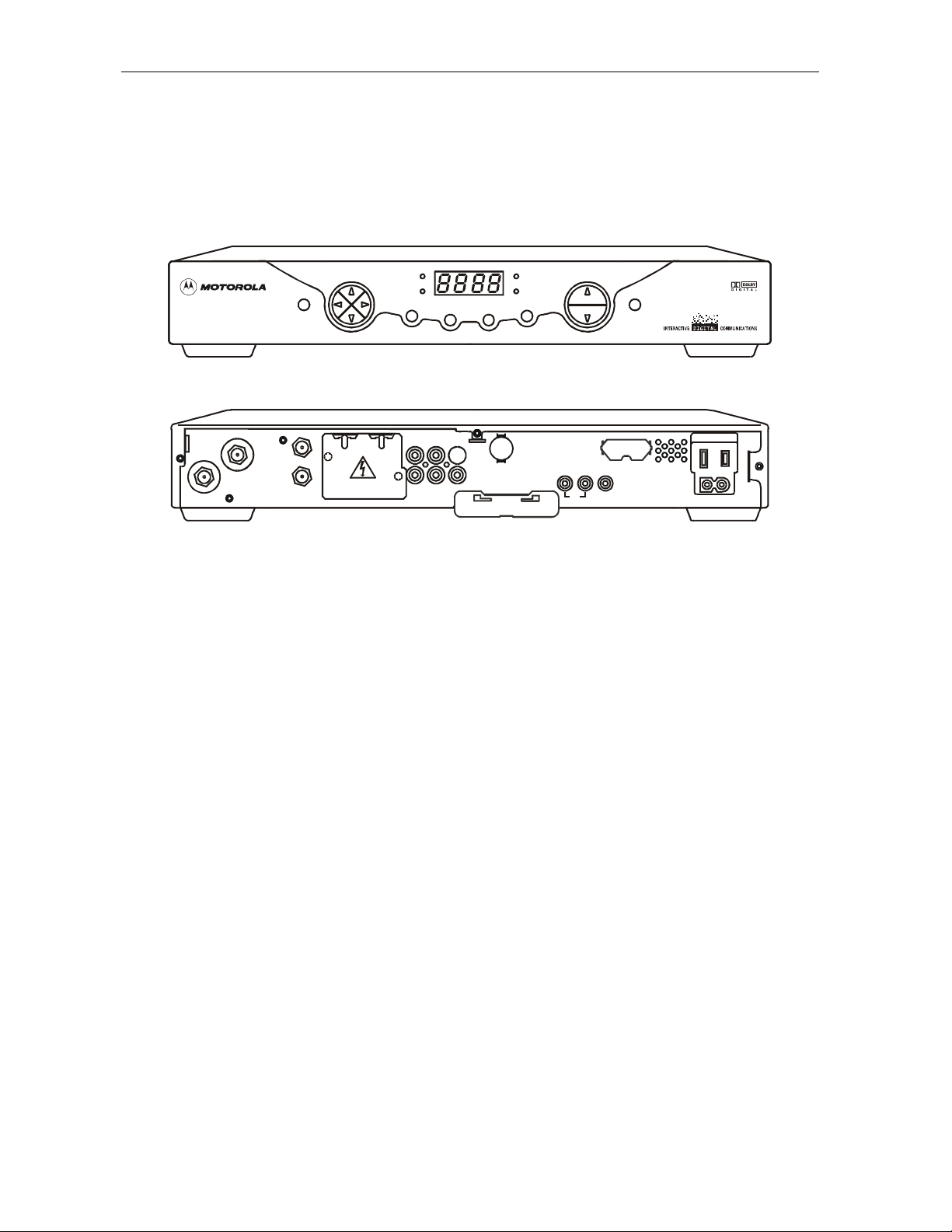
Figure 1-1 illustrates front and rear views of the DCT 2000:
Figure 1-1
DCT 2000 advanced set-top terminal
TV/VCR
CURSOR CHANNEL
TO
RF
IN
TO RF IN
CABLE IN
MESSAGES
A/B POWER
INFO
MENU
AUX AUDIO IN SPDIF
VIDEO
R
L
AUDIO OUT
SELECT
S-VIDEO
TV Pass Card
REMOTE
A/B
HIGH OUT OF
SPEED
DATA
IR
BAND
Using This Manual
This manual provides instructions to install and configure a DCT 2000:
Section 1
Section 2
Introduction provides a product description, a list of related documentation, the technical helpline telephone
number, and the repair/return procedure.
Overview describes the DCT 2000 terminal and provides an overview of its use. This section also identifies the
front-panel displays and switches and describes the rear-panel features.
POWERGUIDE
SWITCHED
105-125V
60Hz
4A MAX
500W MAX
Section 3
Section 4
Section 5
Appendix A
Appendix B
Abbreviations and
Acronyms
Installation provides instructions on how to install the DCT 2000 in a subscriber location and perform
operational tests.
Adding the IR Blaster Option provides instructions on how to install the IR Blaster option for controlling VCR
recording through the DCT 2000.
Troubleshooting provides guidelines for troubleshooting the equipment.
Specifications provide the technical specifications for the DCT 2000.
Diagnostics provide instructions on accessing and interpreting the built-in diagnostics.
The Abbreviations and Acronyms list contains the full spelling of the short forms used in this manual.
DCT 2000 Installation Manual
Page 10

Introduction 1111----3333
Related Documentation
Separate instruction manuals are available for associated components. Although these may be
useful, they are not necessary to install or operate the basic DCT 2000:
DCT 2000 User Guide
§
n DRC 425 Remote Control User Guide
n DRC 400 Remote Control User Guide
n DCT External Add-On Modules Installation Sheet
n STARFONE 2 Installation Sheet
Document Conventions
Before you begin working with this manual and using the DCT 2000, familiarize yourself with
the stylistic conventions used in this manual:
SMALL CAPS
(asterisk)
*
Italic type
Courier font
Denotes silk screening on the equipment, typically representing front- and rear-panel controls, input/output
(I/O) connections, and LEDs
Indicates that several versions of the same model number exist and the information applies to all models;
when the information applies to a specific model, the complete model number is given
Used for emphasis
Displayed text
If You Need Help
If you need assistance while working with the DCT 2000 call the Motorola Technical Response
Center (TRC) at 1-888-944-HELP (1-888-944-4357). The TRC is open from 8:00 AM to 7:00
PM Eastern Time, Monday through Friday. When the TRC is closed, emergency service only is
available on a call-back basis.
When contacting the TRC from outside the United States, call the main switchboard number,
215-323-1000, and ask for extension 4200.
DCT 2000 Installation Manual
Page 11

1111----4444 Introduction
Calling for Repairs
If repair is necessary, call the Motorola Repair Facility at 1-800-227-0450 for a Return for
Service Authorization (RSA) number before sending the unit. The RSA number must be
prominently displayed on all equipment cartons. The Repair Facility is open from 8:00 AM to
5:00 PM Central Time, Monday through Friday.
When calling from outside the United States, use the appropriate international access code and
then call 956-541-0600 to contact the Repair Facility.
When shipping equipment for repair, follow these steps:
1 Pack the unit securely.
2 Enclose a note describing the exact problem.
3 Enclose a copy of the invoice that verifies the warranty status.
4 Ship the unit PREPAID to the following address:
Motorola Corporation
Attn: RSA #___________
5964 E. 14
Brownsville, TX 78521
th
Street
DCT 2000 Installation Manual
Page 12
Section 2
Overview
The DCT 2000 uses state-of-the-art digital compression technology to provide new revenue
generating services. The DCT 2000 can be configured to support real time reverse path
communications, providing a gateway to interactive services such as Video on Demand (VOD),
Internet access, Email, home shopping, and more.
This section provides illustrations and tables showing the DCT 2000 controls, displays and
connectors. Before you begin to install the DCT 2000, familiarize yourself with the various
controls and displays.
Front Panel
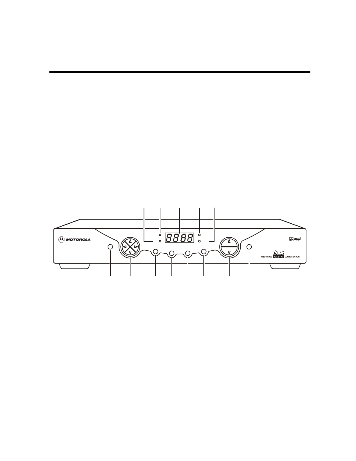
Figure 2-1 illustrates the front panel, which contains selection keys, tuning keys, various
displays, and the power switch:
Figure 2-1
DCT 2000 front panel
12 3 54
CURSOR CHANNEL
MESSAGES
A/B POWER
INFO
MENU SELECT
REMOTE
A/B
POWERGUIDE
131211109876
These controls provide minimum, yet functional capability in the event the remote control is
lost or temporarily out of service. Functions requiring a numeric entry are not available
without a remote control.
DCT 2000 Installation Manual
Page 13
2222----2222 Overview
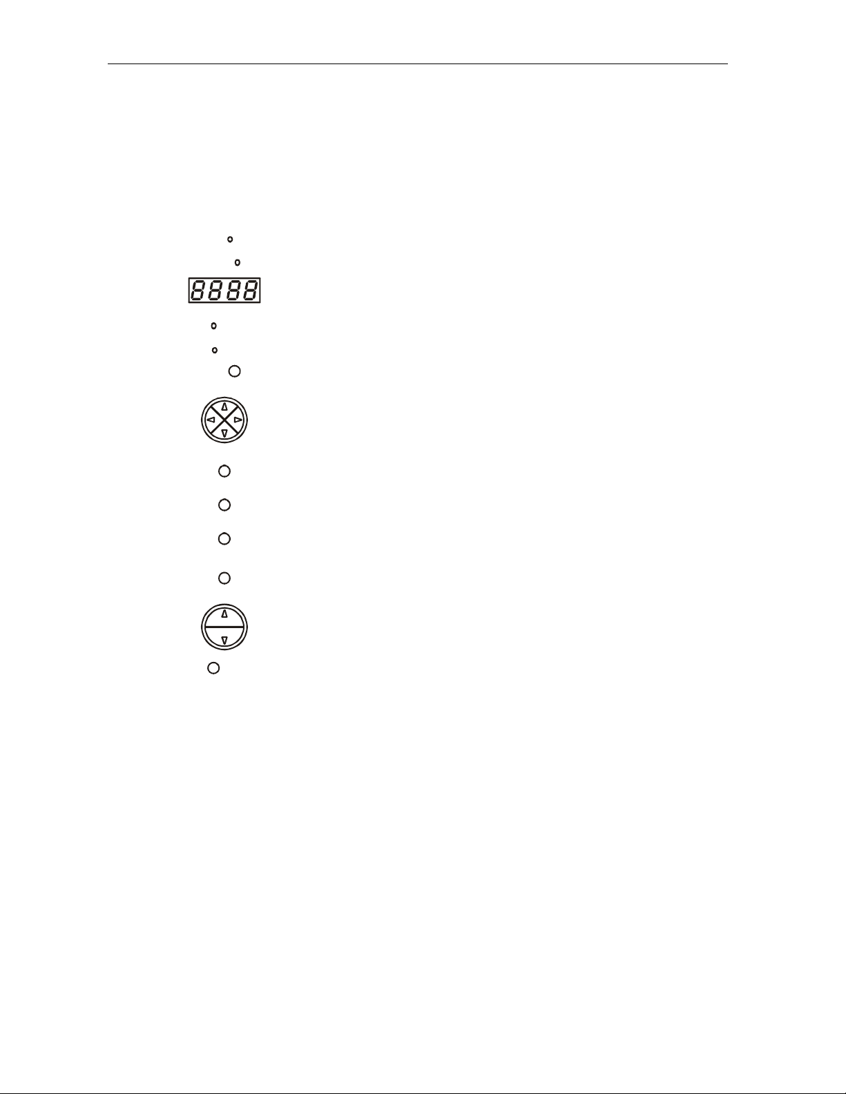
Table 2-1 describes the front-panel controls and LEDs:
Table 2-1
Front panel
Key Feature Function
1
2
A/B
MESSAGES
Lights if optional switch is activated
Lights to indicate that a message is present
10
11
12
13
3
Normally displays current channel number or time of day; in the diagnostic mode, displays
diagnostic codes
GUIDE
REMOTE
POWER
CURSOR
INFO
MENU
SELECT
Flashes when an error-free signal is received from the remote control
Lights when the unit is on
Displays the electronic program guide (EPG)
Moves the cursor in menu and program guide screens
Displays current channel and program information
Displays the Main menu
Selects function options and Pay-Per-View (PPV) events and tunes channels from the
4
5
6
7
8
9
electronic program guide
A/B
CHANNEL
POWER
When enabled, this switches an add-on module from one function to another function
Changes channel up and down
Turns DCT 2000 on/off
DCT 2000 Installation Manual
Page 14
Overview 2222----3333
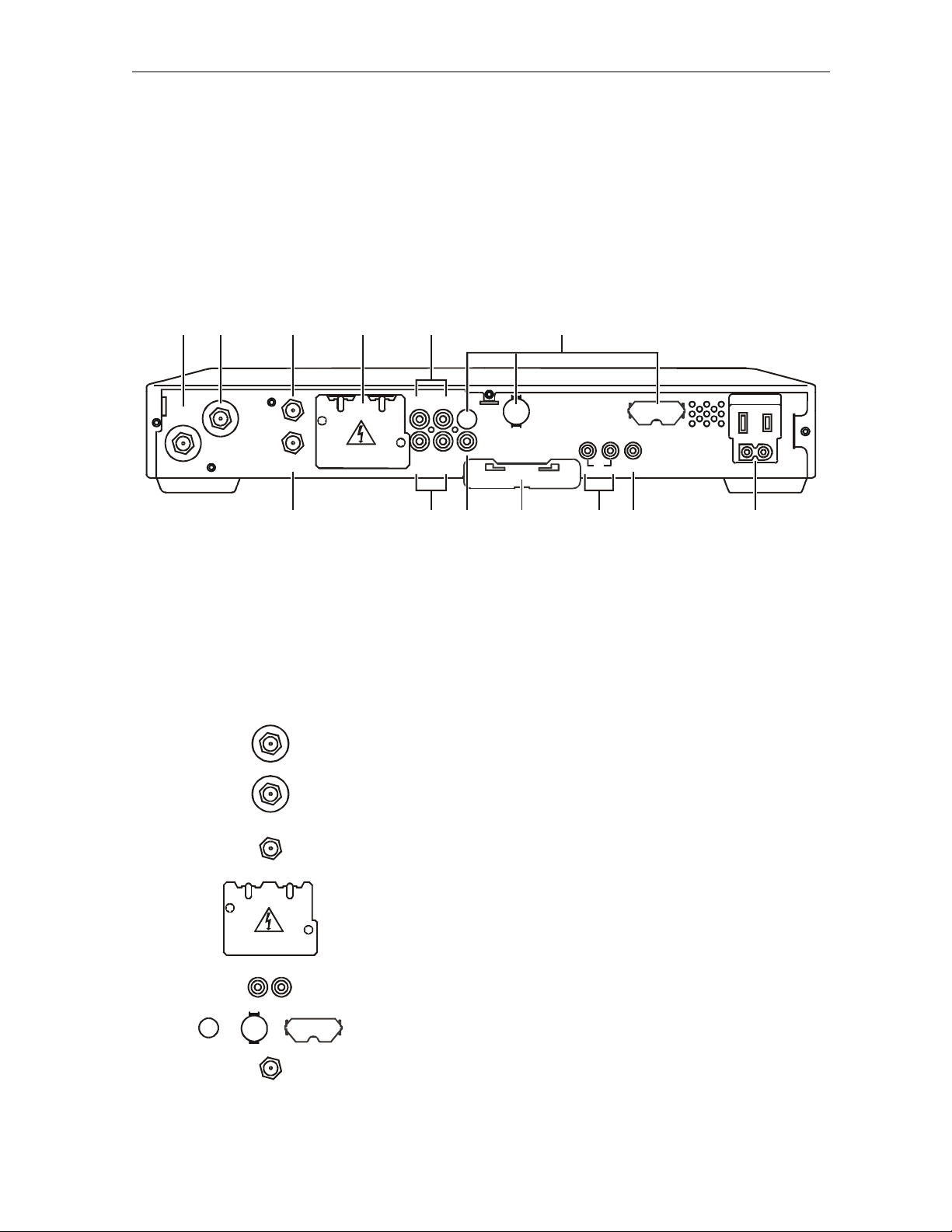
Rear Panel
Figure 2-2 illustrates the rear panel of the DCT 2000 which contains a switched power outlet;
connectors for video, audio, and RF cabling; data output connectors; and IR Blaster output
connector:
Figure 2-2
DCT 2000 rear panel
1
TO
TV/VCR
2
RF
IN
3
TO RF IN
CABLE IN
7
4
5
AUX AUDIO IN SPDIF
VIDEO
R
L
AUD IO OU T
8
S-VIDEO
TV Pass Card
910
6
11
IR
BAND
DATA
12
SWITCHED
105 -125 V
60Hz
4A MA X
500W MA X
13
HIGH OUT OF
SPEED
A protective plate covers the rear panel opening when the optional Telco return is not installed.
Do not remove the protective plate unless you are installing new hardware in the opening.
Table 2-2 describes each of the rear-panel features:
Table 2-2
Rear panel
Key Item Function
TO
1
TV/VCR
F-type connector used to connect the DCT 2000 to a standard TV or VCR
2
RF
IN
3
TO RF IN
4
5
6
AUX AUDIO IN
SPDIF
7
CABLE IN
F-type connector used for DCT 2000 input from the TO RF IN connector
F-type connector used to connect the TO RF IN port to the RF IN port (output from
integrated RF return)
Covers slot used for STARFONE option
RCA jacks for looping through audio from auxiliary audio equipment
Options that enhance your DCT 2000; see, “Options” for more information
F-type connector used for the coaxial cable input port from plant (input to integrated
RF return)
DCT 2000 Installation Manual
Page 15
2222----4444 Overview
Key Item Function
10
11
12
8
LR
AUDIO OUT
9
VIDEO
TV Pass Card
HIGH OUT OF
DATA
IR
BANDSPEED
Left and right audio RCA jacks used for stereo audio output
RCA jack used to connect the DCT 2000 to a composite (baseband) video TV or a
monitor; in some configurations this jack connects to a VCR
Cover for an area reserved for future use
Mini-phone jacks for connecting data output from the DCT 2000
Mini-phone jack for connecting an optional IR Blaster
13
AC power outlet that can be configured as a switched or unswitched outlet and the
two-pronged plug is for attaching a power cord
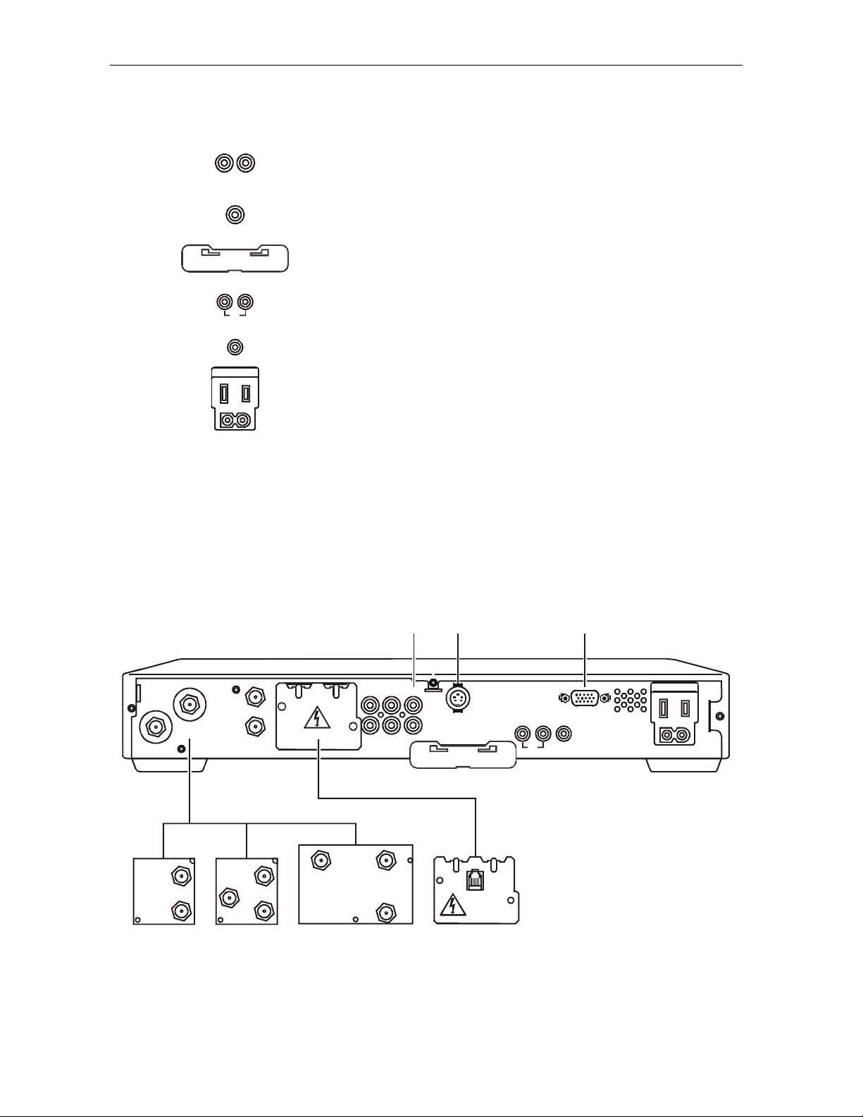
Options
The DCT 2000 supports a variety of options enabling your company to offer a system tailored to
the individual needs of your subscribers. Figure 2-3 illustrates the options available for the
DCT 2000:
Figure 2-3
DCT 2000 options
231
TO
TV/VCR
RF
IN
TO RF IN
CABLE IN
AUX AUDIO IN SPDIF
VIDEO
R
L
AUD IO OU T
S-VIDEO
TV Pass Card
HIGH OUT OF
SPEED
DATA
IR
BAND
SWITCHED
105 -125 V
60Hz
4A MA X
500W MA X
RF
A
CABLEIN
B
RF
OUT
IN
CONV
IN
45 6 7
DCT 2000 Installation Manual
A
RFOUT
PHONE
B
Page 16
Overview 2222----5555
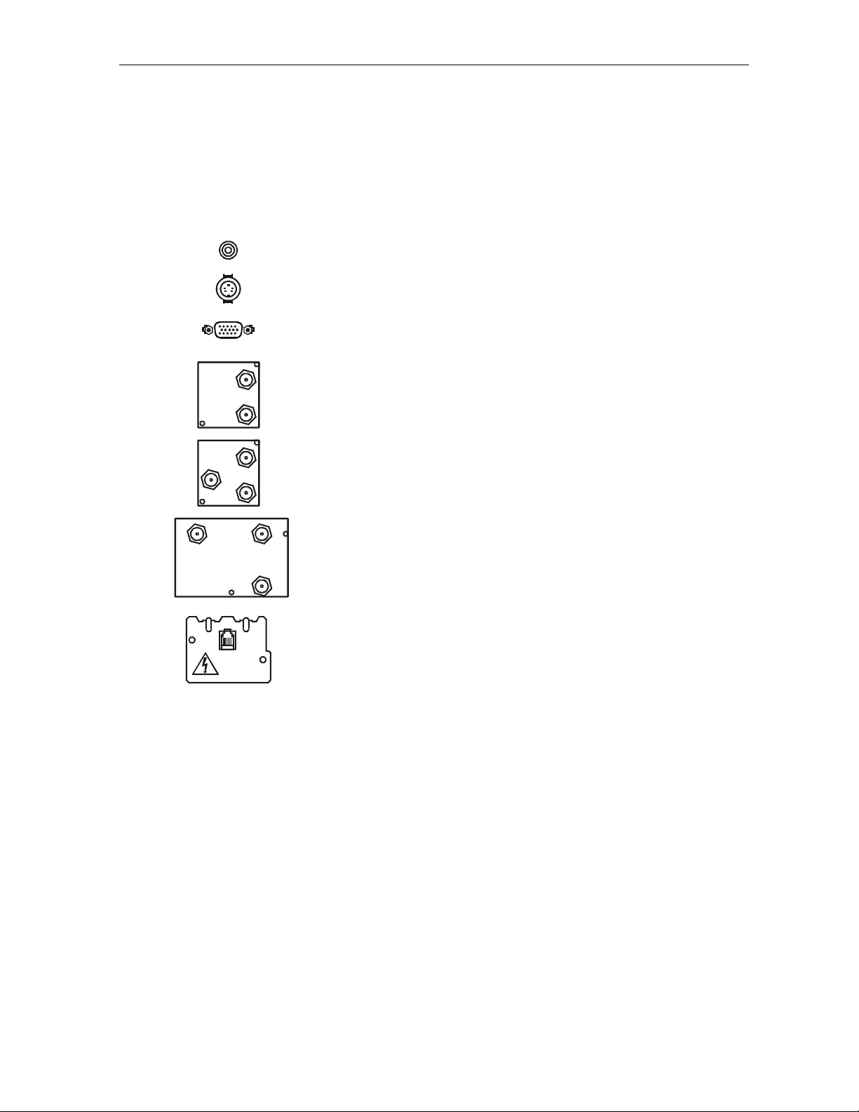
Table 2-3 describes the function of each of the options shown in Figure 2-3:
Table 2-3
Options
Key Option Name Function
1
SPDI F
SPDIF
Used to deliver Dolby Digital 5.1, Dolby AC3 audio, or PCM audio
(digital audio recording)
2
S-VIDEO
3
S-VIDEO
PARALLEL PORT
Used for high quality video to external devices such as high-end
VCRs or TVs
Interface this serial data connector to an external data device such
as a printer
4
5
6
RFOUT
CABLEIN
RF
OUT
A
B
RF
IN
CONV
IN
A
B
7
A/B In
RF Bypass
Dual A/B RF Bypass
STARFONE
Used in a dual cable system to receive both cables; verify the
location of the A and B connectors on your particular A/B In
module
Enables the cable signal to bypass the DCT 2000 and go directly to
a TV or VCR
Used in a dual cable system; enables the cable signal on the
current side (A or B) to go directly to a TV or VCR
Used in a two-way addressable system to send Impulse
Pay-Per-View (IPPV) information to the DAC 6000 or other
PHONE
controller through the subscriber’s telephone hookup
DCT 2000 Installation Manual
Page 17

2222----6666 Overview
Remote Controls
The basic DCT 2000 uses the DRC 400 remote control. If your system offers optional interactive
applications, such as an interactive program guide, a different remote control may be required.
The application provider should supply user instructions for each interactive application.
DRC 400 Remote Control
Figure 2-4 illustrates the DRC 400:
Figure 2-4
DRC 400 remote control
1
10
11
12
13
VCR CABLE
AUX
2
3
4
EXIT
HELP
PAGE
POWER
LOCK
5
6
OK
7
8
9
REW
A
1
4
7
TV/VCR
DAY
STOP
LAST
FAVORITE
PAUSE
RECORD
TV
15
PAGE
INFO
16
17
MENU
CHANNELVOLUME
18
19
20
B
C
2
3
5
6
8
9
ENTER
0
DAY
PLAY
F.FWD
21
22
14
DCT 2000 Installation Manual
Page 18

Table 2-4describes the remote control keys:
Table 4
Remote control keys
Key Item Description
1 AUX, VCR, CABLE, or TV
Selects a desired device to control. The selected mode will remain active until you press
another key.
Overview 2222----7777
2HELP
3POWER
4 PAGE
5 EXIT
6
7 OK/SELECT
8 GUIDE
9VOLUME + or
10 A, B , or C
11 NUMBER KEYS
12 TV/VCR
13
14 STOP, PAUSE, PLAY, REW,
or PAGE
▲
▲
▲ ▲
VOLUME -
BYPASS
Day
◄◄◄◄
Day
►►►►
RECORD, F.FWD
▼▼▼▼
Displays the help screen.
Turns the selected home entertainment component on or off.
Pages through menu screens and the program guide.
Exits a menu or program guide.
Moves the cursor around the program guide and menu screens.
Selects menu options, Pay-Per-View events or tune programs from the program guide.
Your remote may only have OK; this key still performs the same functions.
Displays the program guide.
Increases or decreases the volume of the currently selected device.
Functionality is determined from services offered by the service provider.
Directly selects a channel.
Enables the RF bypass function. A cable-ready TV is required for this function to operate.
Moves the program guide ahead or back 24 hours.
Controls the VCR.
15 MUTE
16 LOCK/PPV
17 INFO
18 MENU
19 LAST
20 CHANNEL + or -
21 FAVORITE
22 ENTER/MUSIC
Toggles the sound on and off.
Limits viewing of selected programs; and is used to view the Pay-Per-View menu. Your
remote may have only LOCK; this key still performs the same functions.
Displays the current channel and program information (not supported by all
applications).
Displays the Main menu.
Recalls the last channel or goes back one screen in the menu.
Changes the channels by moving up or down.
Displays preset favorite cable channels.
Displays digital music channel menus. On some TV models, press to enter channels.
DCT 2000 Installation Manual
Page 19
2222----8888 Overview
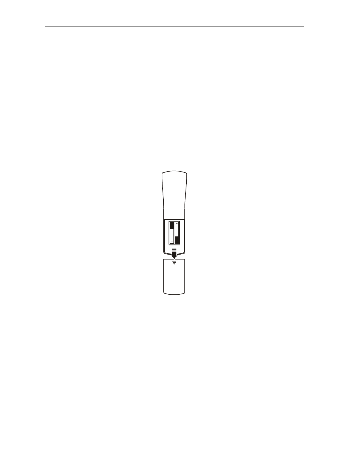
Installing Batteries in Remote Control
Before using the remote control, you must install two AA (1.5 V) alkaline batteries. Figure 2-5
illustrates battery access on the back of the remote control.
To install batteries in an DRC 400:
1 Press and slide the battery compartment cover off.
2 Place the batteries in the compartment; be careful to observe the correct polarity.
3 Slide the battery compartment cover back into place.
Battery installation will vary with each style of remote control. Refer to the user instructions
included with your remote control for installing batteries.
Figure 2-5
Back view of remote control
+
+
DCT 2000 Installation Manual
Page 20

Section 3
Installation
This section provides instructions for installing and cabling the DCT 2000. To complete the
installation, you must:
Connect the cables
§
Supply power to equipment
§
Download configuration information and software
§
Run operational check and diagnostics
§
Before You Begin
Before you begin, review the installation instructions, gather the required items, and complete
the tasks listed below:
Determine if the subscriber’ssystem requirements include an A/B In, RF Bypass, Dual
§
A/B-RF Bypass module, or a STARFONE module. These options can be installed before
leaving the office. Installation instructions are provided with these modules.
Verify that you have 75-ohm coaxial cables with F-type connectors and RCA baseband
§
phonotype cables.
Determine if you are connecting the DCT 2000 to a standard TV or a composite (baseband)
§
monitor.
Place the DCT 2000 on a smooth, flat surface and remove any obstructions that could
§
interfere with the free flow of air over, under, or around it. Advise the subscriber not to
place anything on top of the unit.
Installing the DCT 2000
To install the DCT 2000:
1 If an add-on module is required and it was not previously installed, do that now. When
installed, verify that the appropriate configuration information has been downloaded via
the access control system.
2 Determine if you are connecting the DCT 2000 to a conventional TV or to a monitor. To
install the video connection:
For a conventional TV, use a 75-ohm coaxial cable with F-type connectors.
§
Foramonitor,useanRCAphonocabletoconnectthe
§
3 Locate the cabling diagram that matches the subscriber’s configuration requirement.
4 Connect the cables as illustrated in the diagram.
5 Perform the basic operational check in this section after the DCT 2000 is installed.
VIDEO connector to the monitor.
DCT 2000 Installation Manual
Page 21
3333----2222 Installation
Standard Cabling Diagram
The DCT 2000 will output on either channel 3 or 4 depending on the configuration message
from the control system. Figure 3-1 illustrates a standard diagram connecting the DCT 2000 to
a TV using RF connectors:
Figure 3-1
Standard cabling
TO
TV/VCR
RF
IN
TO RF IN
CABLE IN
AUX AUDIO IN SPDIF
VIDEO
R
L
AUD IO OU T
S-VIDEO
TV Pass Card
HIGH OUT OF
SPEED
DATA
IR
BAND
SWITCHED
105 -125 V
60Hz
4A MAX
500W MA X
From cable outlet
AUDIO
IN
LR
CABLE IN
AUDIO
OUT
LR
VIDEO
SVIDEO
IN
IN
TV
The remodulated channel, 3 or 4, does not carry stereo for digital channels. Connect the
DCT 2000 using RCA baseband connectors to receive stereo on digital channels. These
connections are illustrated later in this section.
DCT 2000 Installation Manual
Page 22
Installation 3333----3333
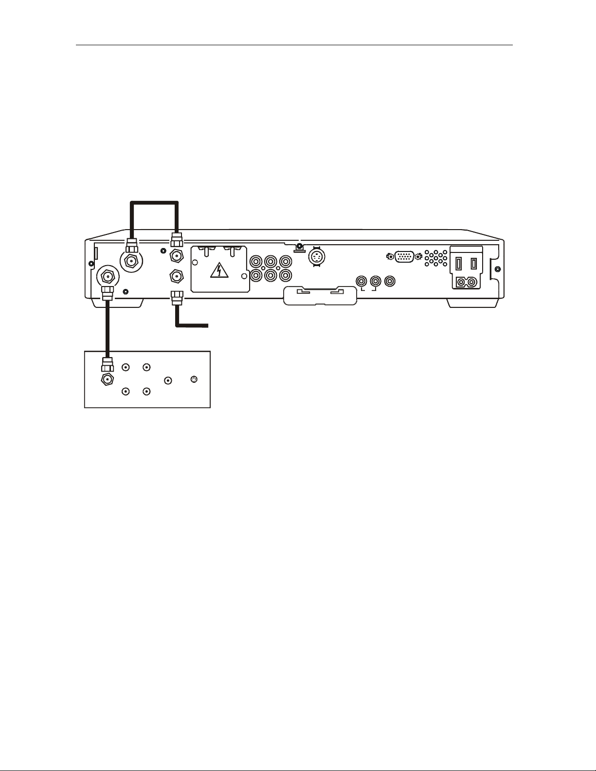
STARFONE module cabling diagram
Figure 3-2 illustrates the RF wiring diagram for the DCT 2000 when it has a telephone return
modem:
Figure 3-2
Standard wiring with a STARFONE module
TO
TV/VCR
RF
IN
TO RF IN
PHONE
CABLE IN
AUX AUDIO IN SPDIF
VIDEO
R
L
AUD IO OU T
S-VIDEO
TV Pass Card
HIGH OUT OF
SPEED
DATA
IR
BAND
SWITCHED
105 -125 V
60Hz
4A MA X
500W MA X
Subscriber telephonehookup
From cable outlet
AUDIO
IN
LR
CABLE IN
AUDIO
OUT
LR
VIDEO
IN
SVIDEO
IN
TV
For service providers planning to implement RF return capabilities, it is recommended the
DCT 2000 be wired for both the STARFONE telephone return and the integrated STARVUE
RF return. This enables the operator to move the DCT 2000 into a two-way RF return without
rewiring the DCT 2000 later.
DCT 2000 Installation Manual
Page 23
3333----4444 Installation
Standard VCR Cabling Diagram
Figure 3-3 illustrates the basic cabling diagram that enables you to record the channel being
viewed:
Figure 3-3
Standard VCR cabling
TO
TV/VCR
RF
IN
TO RF IN
CABLE IN
AUX AUDIO IN SPDIF
VIDEO
R
L
AUD IO OU T
S-VIDEO
TV Pass Card
HIGH OUT OF
SPEED
DATA
IR
BAND
SWITCHED
105 -125 V
60Hz
4A MA X
500W MA X
From cable source
AUDIO
CABLE IN VIDEO IN
CABLE OUT VIDEO OUT
AUDIO
IN LR
AUDIO
OUT
LR
SVIDEO IN
CABLE IN
SVIDEO OUT
VCR
IN
AUDIO
OUT
LR
SVIDEO
VIDEO
LR
IN
IN
TV
The remodulated channel, 3 or 4 does not carry stereo for digital channels. Connect the
DCT 2000 using RCA baseband connectors to receive stereo on digital channels. These
connections are illustrated later in this section.
DCT 2000 Installation Manual
Page 24
Installation 3333----5555
RF Bypass Switch VCR Cabling Diagrams
Proper operation of the RF Bypass feature requires special configuration in the control system
and in the EPG settings.
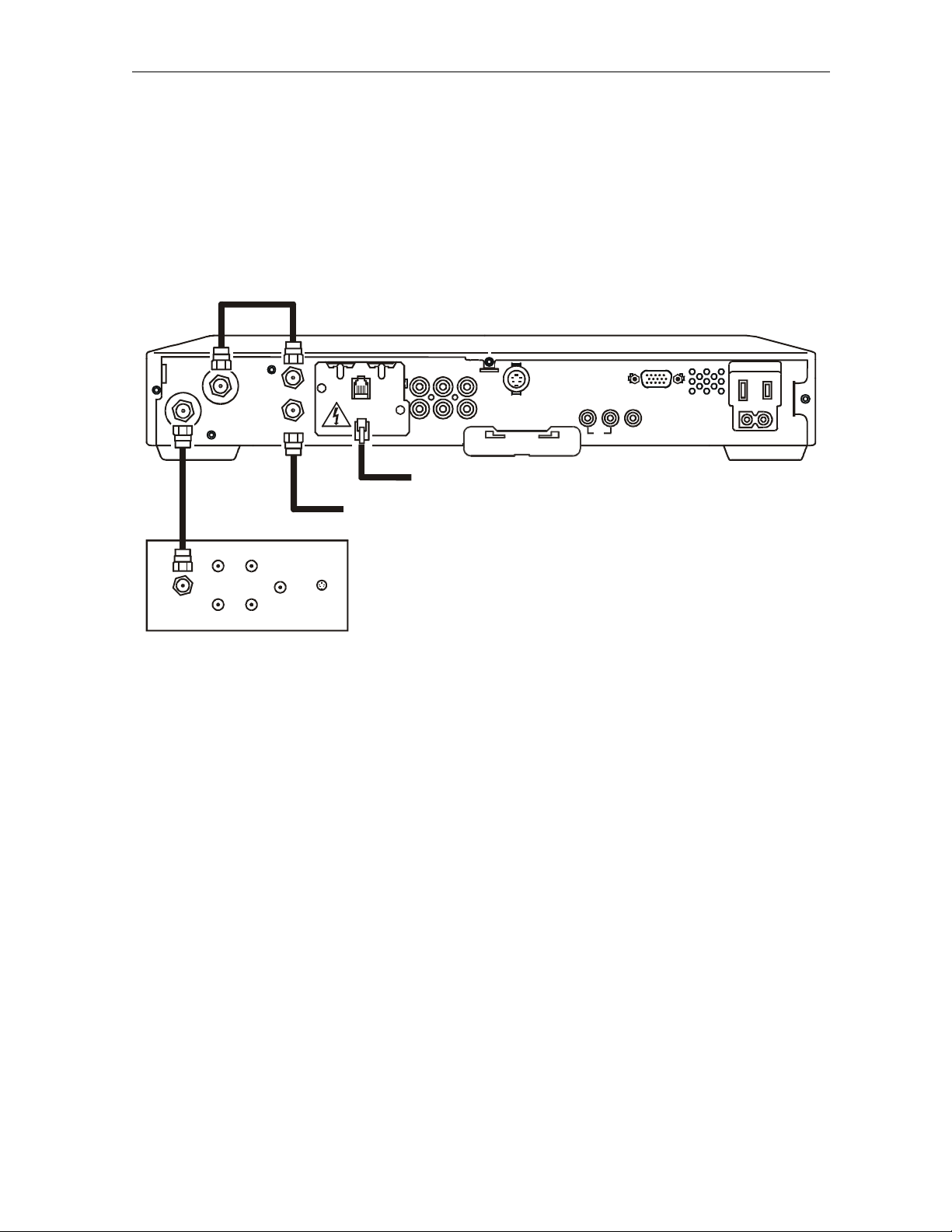
The STARFONE return module is used in a one-way addressable system to send information to
the controller through the subscriber’s telephone hookup. Figure 3-4 illustrates the cabling
diagram that enablesviewing an unscrambled analog channel on TV while recording another
channel through the DCT 2000:
Figure 3-4
RF Bypass switch with VCR (STARFONE return module installed)
From cable source
TO
TV/VCR
RF
OUT
RF
IN
TO RF IN
CONV
RF
IN
IN
CABLE IN
PHONE
AUX AUDIO IN SPDIF
VIDEO
R
L
AUD IO OU T
S-VIDEO
TV Pass Card
HIGH OUT OF
SPEED
DATA
IR
BAND
SWITCHED
105-125V
60Hz
4A MA X
500W MA X
Subscriber telephonehookup
AUDIO
IN
AUDIO
CABLE IN VIDEO IN
CABLE OUT VIDEO OUT
IN
AUDIO
OUT
LR
LR
SVIDEO IN
SVIDEO OUT
VCR
CABLE IN
AUDIO
OUT
LR
SVIDEO
VIDEO
LR
IN
IN
TV
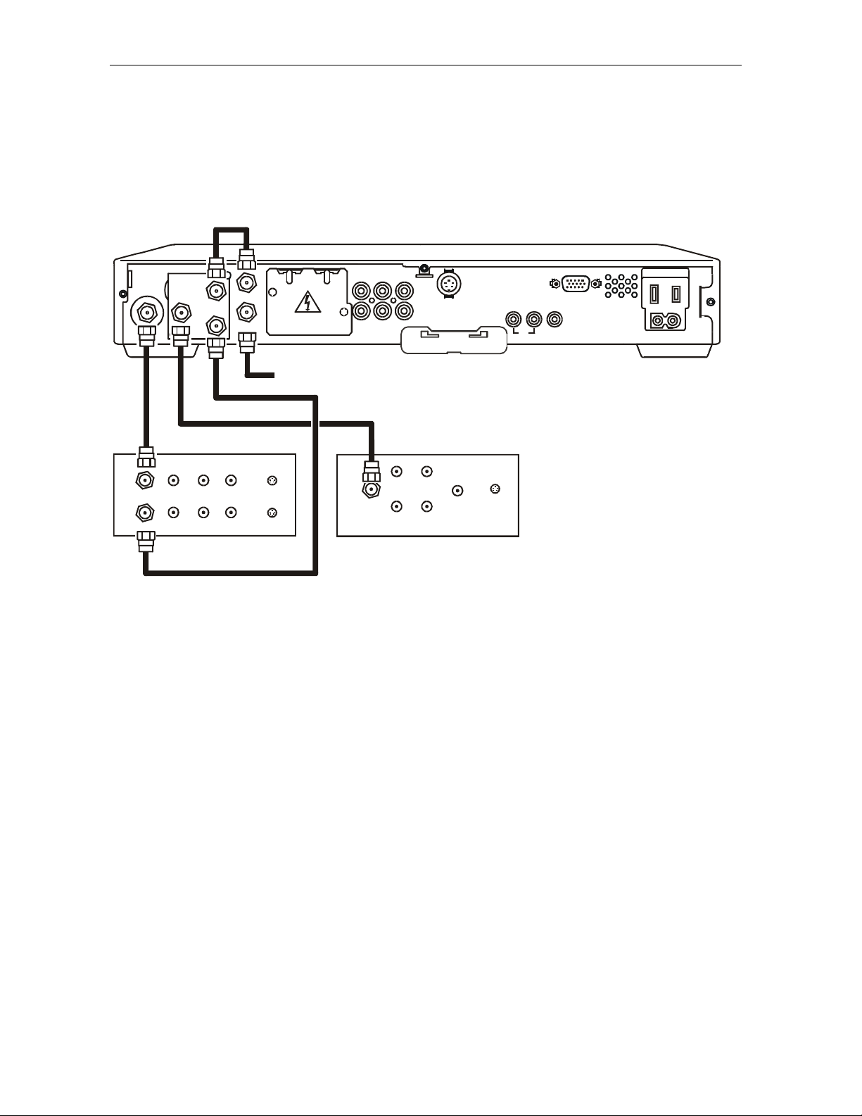
If the operator plans to implement two-way RF return functionality in the future, the installer
should use the integrated STARVUE RF return.
DCT 2000 Installation Manual
Page 25
3333----6666 Installation
Figure 3-5 illustrates the cabling diagram that uses the RF return and enables viewing of an
unscrambled analog channel on TV while recording another channel through the DCT 2000:
Figure 3-5
Cabling with RF Bypass module (using RF return)
TO
TV/VCR
CABLE IN VIDEO IN
CABLE OUT VIDEO OUT
RF
OUT
RF
IN
AUDIO
AUDIO
OUT
RF
IN
TO RF IN
CONV
IN
CABLE IN
IN LR
LR
From cable source
SVIDEO IN
SVIDEO OUT
VCR
AUX AUDIO IN SPDIF
VIDEO
R
L
AUD IO OU T
CABLE IN
AUDIO
IN
AUDIO
OUT
LR
LR
S-VIDEO
TV Pass Card
VIDEO
IN
SVIDEO
IN
HIGH OUT OF
SPEED
TV
IR
BAND
DATA
SWITCHED
105-125V
60Hz
4A MA X
500W MA X
DCT 2000 Installation Manual
Page 26

Installation 3333----7777
A/B In Module Cabling Diagrams
The A/B In module is commonly used in dual-cable systems. Figure 3-6 illustrates a DCT 2000
that is equipped with a STARFONE module:
Figure 3-6
A/B In module with a STARFONE module
CableA
TO
TV/VCR
CABLEIN
RF
IN
A
TO RF IN
B
CABLE IN
PHONE
AUX AUDIO IN SPDIF
VIDEO
R
L
AUD IO OU T
S-VIDEO
TV Pass Card
Subscriber telephone hookup
Cable B
AUDIO
IN
LR
CABLE IN
AUDIO
OUT
LR
VIDEO
SVIDEO
IN
IN
TV
Figure 3-7 illustrates a DCT 2000 with the return on Cable A:
Figure 3-7
A/B In module with return on Cable A
RF OUT
TO
TV/VCR
A
RF
IN
B
TO RF IN
CABLE IN
AUX AUDIO IN SPDIF
VIDEO
R
L
AUD IO OU T
S-VIDEO
TV Pass Card
HIGH OUT OF
SPEED
DATA
HIGH OUT OF
SPEED
DATA
IR
BAND
IR
BAND
SWITCHED
105 -125 V
60Hz
4A MA X
500W MA X
SWITCHED
105 -125 V
60Hz
4A MA X
500W MA X
TV
CABLE IN
AUDIO
IN
AUDIO
OUT
CableA (Return)
Cable B
LR
SVIDEO
VIDEO
IN
IN
LR
DCT 2000 Installation Manual
Page 27

3333----8888 Installation
Figure 3-8 illustrates a DCT 2000 when the return is on Cable B:
Figure 3-8
A/B In module with return on Cable B
CableA
TV
TO
TV/VCR
CABLE IN
CABLEIN
RF
IN
AUDIO
IN
AUDIO
OUT
AUX AUDIO IN SPDIF
A
TO RF IN
VIDEO
R
B
CABLE IN
AUD IO OU T
L
S-VIDEO
TV Pass Card
HIGH OUT OF
SPEED
IR
BAND
DATA
SWITCHED
105 -125 V
60Hz
4A MA X
500W MA X
Cable B (Return)
LR
SVIDEO
VIDEO
IN
IN
LR
DCT 2000 Installation Manual
Page 28

Installation 3333----9999
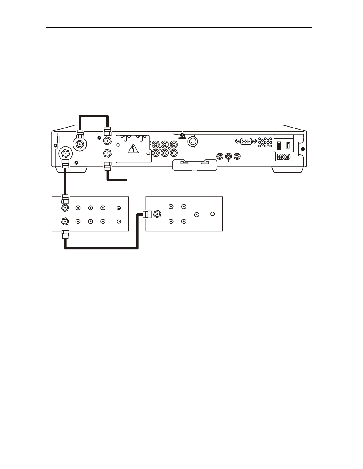
Dual A/B-RF Bypass Module Cabling Diagrams
The Dual A/B-RF Bypass module is commonly used in dual-cable systems. Both Cable A and
Cable B are cable signals coming from the service provider. The service provider determines
which source will be the return cable. Choose the cabling diagram that matches the return
configuration you need.
The Dual A/B cable system using a STARFONE module utilizes the telephone modem as the
return path to the service provider. Figure 3-9 illustrates a DCT 2000 with a STARFONE
module:
Figure 3-9
Return on STARFONE module
CableA
TV
RF OUT
CABLE IN
AUDIO
AUDIO
OUT
A
TO RF IN
PHONE
B
CABLE IN
AUX AUDIO IN SPDIF
VIDEO
R
L
AUD IO OU T
S-VIDEO
TV Pass Card
HIGH OUT OF
SPEED
DATA
IR
BAND
SWITCHED
105 -125 V
60Hz
4A MA X
500W MA X
Subscriber telephonehookup
Cable B
IN
LR
SVIDEO
VIDEO
LR
IN
IN
DCT 2000 Installation Manual
Page 29

3333----10
10 Installation
1010
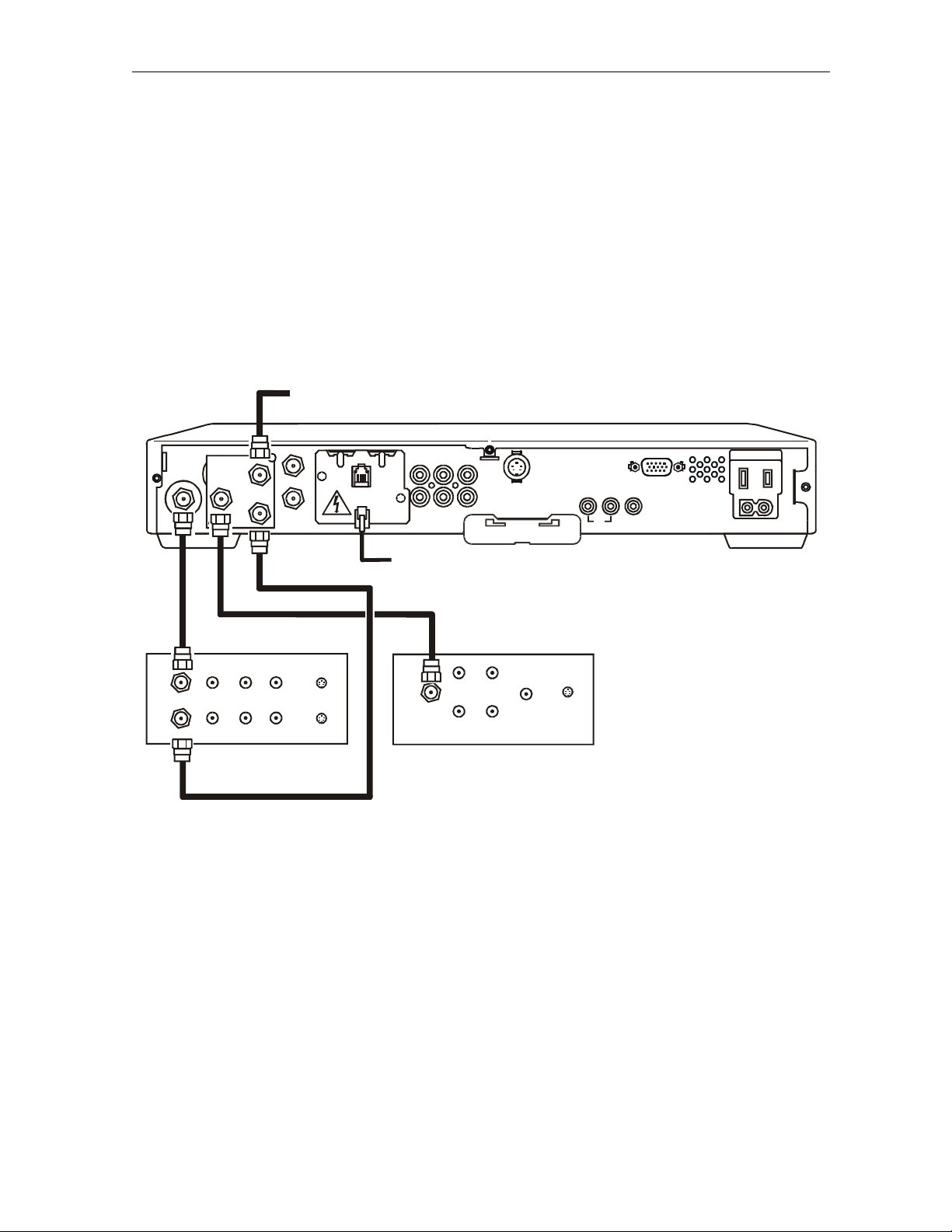
Figure 3-10 illustrates a DCT 2000 with the Dual A/B RF Bypass module when the return is on
Cable A:
Figure 3-10
Return on Cable A
RF OUT
TO
TV/VCR
A
RF
IN
B
TO RF IN
CABLE IN
AUX AUDIO IN SPDIF
VIDEO
R
L
AUD IO OU T
S-VIDEO
TV Pass Card
HIGH OUT OF
SPEED
DATA
IR
BAND
SWITCHED
105 -125 V
60Hz
4A MA X
500W MA X
CableA (Return)
Cable B
AUDIO
IN
LR
CABLE IN
AUDIO
OUT
LR
VIDEO
SVIDEO
IN
IN
TV
Figure 3-11 illustrates a DCT 2000 with a Dual A/B RF Bypass module when the return is on
Cable B:
Figure 3-11
Return on Cable B
CableA
A
RF OUT
CABLE IN
AUDIO
IN
AUDIO
OUT
B
TO RF IN
CABLE IN
LR
SVIDEO
VIDEO
LR
IN
IN
TV
DCT 2000 Installation Manual
AUX AUDIO IN SPDIF
R
AUD IO OU T
Cable B (Return)
S-VIDEO
VIDEO
L
TV Pass Card
HIGH OUT OF
SPEED
IR
BAND
DATA
SWITCHED
105-125V
60Hz
4A MA X
500W MA X
Page 30

Installation 3333----11
Composite Baseband and S-Video Cabling Diagrams
11
1111
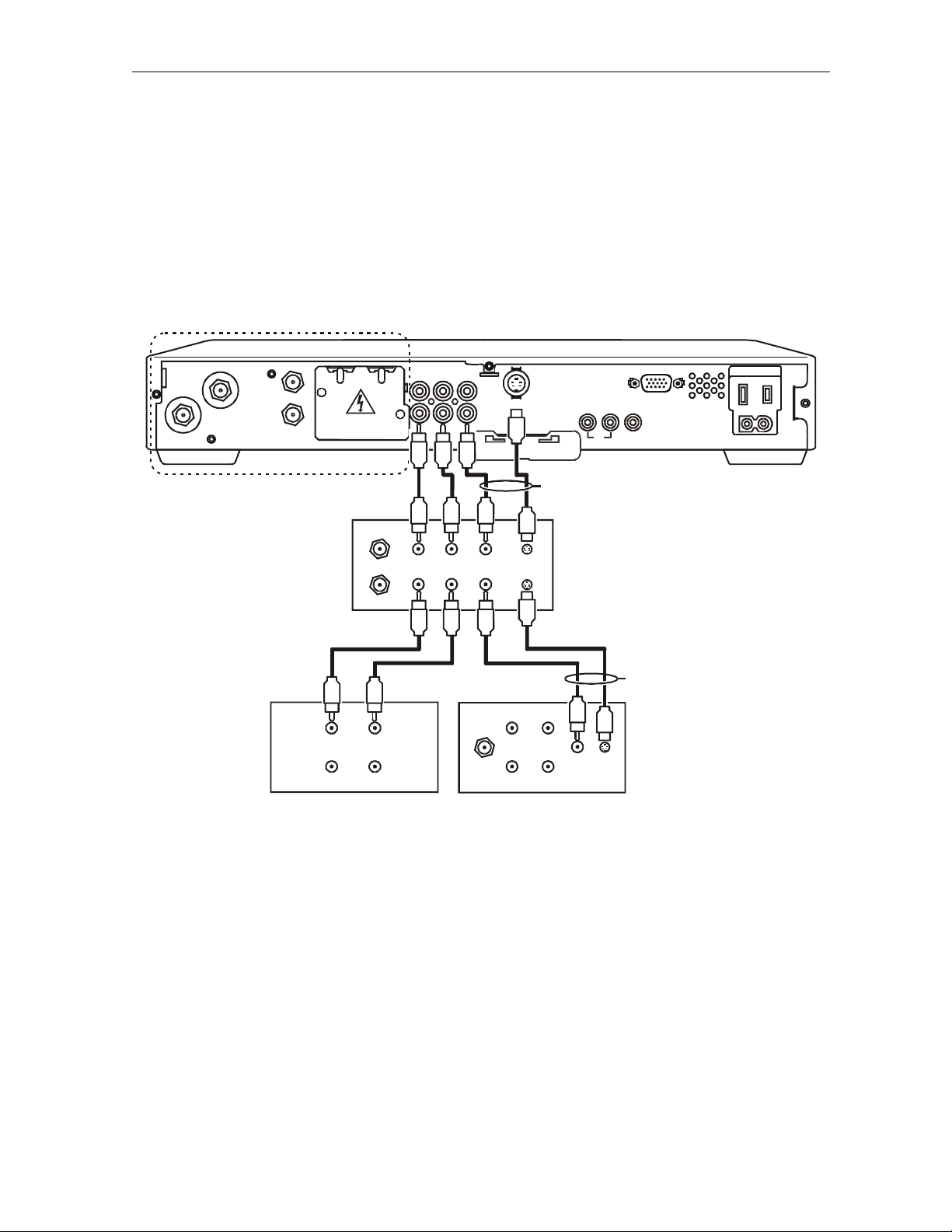
Connecting the DCT 2000 using the baseband RCA type outputs enables the subscriber to
experience stereo and Dolby Surround
â
sound on digital channels when available.
Figure 3-12 illustrates the standard baseband audio and video outputs of the DCT 2000:
Figure 3-12
Standard baseband cabling
See appropriate
cable diagram
TO
TV/VCR
RF
IN
TO RF IN
CABLE IN
AUX AUDIO IN SPDIF
VIDEO
R
L
AUD IO OU T
S-VIDEO
TV Pass Card
HIGH OUT OF
SPEED
DATA
IR
BAND
SWITCHED
105 -125 V
60Hz
4A MA X
500W MA X
Either or
AUDIO
IN
LR
CABLE IN
AUDIO
OUT
LR
VIDEOINSVIDEO
IN
TV
The S-Video connector is part of the Home Theatre option and is not included on all
DCT 2000s.
When connecting the video path, never connect baseband composite video and S-Video together.
Because some entertainment equipment will not support both video inputs simultaneously, use
only one connection path.
DCT 2000 Installation Manual
Page 31

3333----12
12 Installation
1212
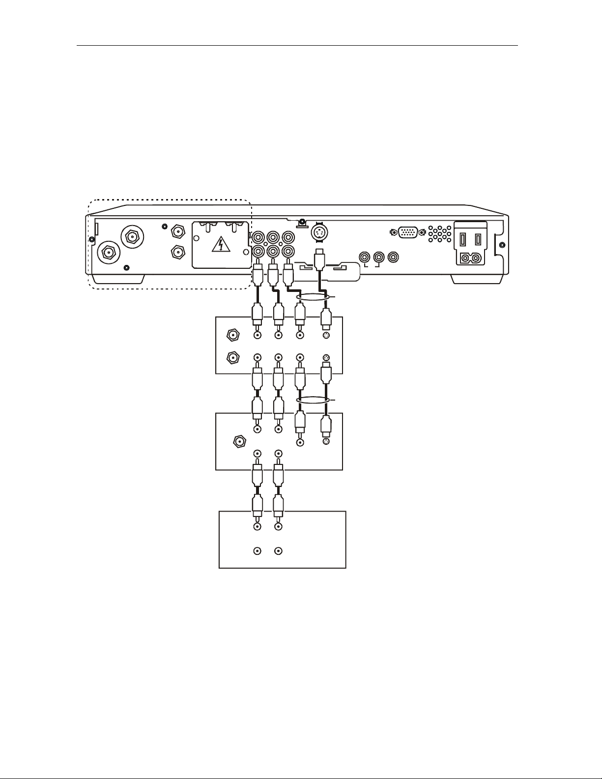
Figure 3-13 illustrates the baseband audio and video outputs of the DCT 2000 that are
available to connect to a VCR:
Figure 3-13
Composite VCR cabling
See appropriate
cable diagram
TO
TV/VCR
RF
IN
TO RF IN
CABLE IN
AUX AUDIO IN SPDIF
VIDEO
R
L
AUD IO OU T
S-VIDEO
TV Pass Card
HIGH OUT OF
SPEED
DATA
IR
BAND
SWITCHED
105 -125 V
60Hz
4A MA X
500W MA X
Either or
AUDIO
CABLE IN VIDEO IN
CABLE OUT VIDEOOUT
IN
AUDIO
OUT
LR
LR
SVIDEO IN
SVIDEO OUT
VCR
Either or
AUDIO
IN
LR
CABLE IN
AUDIO
OUT
LR
VIDEO
SVIDEO
IN
IN
TV
When connecting the video path, never connect baseband composite video and S-Video together.
Because some entertainment equipment will not support both video inputs simultaneously, use
only one connection path.
DCT 2000 Installation Manual
Page 32
Installation 3333----13
Stereo Cabling Diagram (Baseband)
This audio configuration does not provide for a TV playing through the stereo. Figure 3-14
illustrates how to connect the DCT 2000 to a stereo using the audio connectors on the VCR:
Figure 3-14
Audio on the VCR
See appropriate
cable diagram
13
1313
TO
TV/VCR
AUX AUDIO IN SPDIF
RF
IN
TO RF IN
CABLE IN
R
AUD IO OU T
L
VIDEO
S-VIDEO
TV Pass Card
HIGH OUT OF
SPEED
IR
BAND
DATA
SWITCHED
105 -125 V
60Hz
4A MA X
500W MA X
Either or
CABLE IN VIDEO IN
CABLE OUT VIDEOOUT
AUDIO
IN LR
AUDIO
OUT
SVIDEO IN
LR
SVIDEO OUT
VCR
Either or
AUDIO
IN
AUDIO
OUT
LR
LR
VIDEOINSVIDEO
IN
STEREO
AUDIO
IN LR
AUDIO
OUT LR
CABLE IN
TV
When connecting the video path, never connect baseband composite video and S-Video together.
Because some entertainment equipment will not support both video inputs simultaneously, use
only one connection path.
DCT 2000 Installation Manual
Page 33
3333----14
14 Installation
1414
This audio configuration enables the TV to play through the stereo. Figure 3-15 shows how to
connect the DCT 2000 to a stereo using the audio loop-through connectors on the VCR and the
audio output ports on the TV monitor:
Figure 3-15
Audio on VCR/audio output on TV
See appropriate
cable diagram
TO
TV/VCR
AUX AUDIO IN SPDIF
RF
IN
TO RF IN
CABLE IN
R
AUD IO OU T
VIDEO
L
S-VIDEO
TV Pass Card
HIGH OUT OF
SPEED
IR
BAND
DATA
SWITCHED
105 -125 V
60Hz
4A MA X
500W MA X
Either or
AUDIO
CABLE IN VIDEO IN
CABLE OUT VIDEOOUT
IN
AUDIO
OUT
LR
LR
SVIDEO IN
SVIDEO OUT
VCR
Either or
AUDIO
IN
L
R
CABLE IN
R
AUDIO
OUT
L
VIDEO
SVIDEO
IN
IN
TV
AUDIO
IN
L
R
AUDIO
OUT
L
R
STEREO
When connecting the video path, never connect baseband composite video and S-Video together.
Because some entertainment equipment will not support both video inputs simultaneously, use
only one connection path.
DCT 2000 Installation Manual
Page 34
Installation 3333----15
15
1515
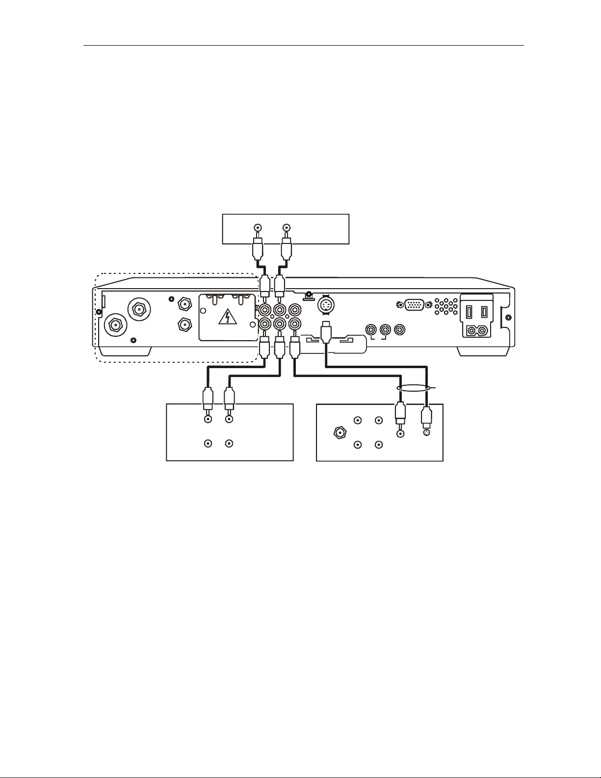
When all of the RCA audio connectors on the back of the stereo receiver are used, the
DCT 2000 enables audio to pass through an external device such as a CD player. In this
configuration, a subscriber’s CD player can be played through the DCT 2000 to a stereo
receiver. Figure 3-16 illustrates how to connect the RCA baseband auxiliary audio input/output
on the DCT 2000:
Figure 3-16
CD player cabling
CD PLAYER
AUDIO
OUT
RR
See appropriate
cable diagram
TO
TV/VCR
RF
IN
TO RF IN
CABLE IN
AUX AUDIO IN SPDIF
VIDEO
R
L
AUD IO OU T
S-VIDEO
TV Pass Card
HIGH OUT OF
SPEED
DATA
IR
BAND
SWITCHED
105 -125 V
60Hz
4A MA X
500W MA X
Either or
STEREO
R
R
AUDIO
IN
AUDIO
OUT
L
CABLE IN
L
TV
R
R
AUDIO
IN
AUDIO
OUT
L
SVIDEO
VIDEO
L
IN
IN
The DCT 2000 must be turned off from the front panel to enable audio loop-through signals to
pass through. When the DCT 2000 is powered on, the audio outputs correspond with the
currently tuned channel on the DCT 2000.
DCT 2000 Installation Manual
Page 35

3333----16
16 Installation
1616
Dolby Digital Cabling Diagrams
The DCT 2000 can deliver Dolby AC-3 audio to a Dolby Digital stereo receiver using the SPDIF
RCA connector. Because the SPDIF does not carry audio for analog channels, use both the
baseband L/R audio and the SPDIF connectors when connecting the DCT 2000 to a digital
receiver.
PCM audio and AC-3 are the operation modes for the SPDIF connector. PCM audio mode is the
default setting from the factory. Use the Electronic Program Guide (EPG) to select an
alternative operating mode for the DCT 2000. If the EPG does not provide a PCM or AC-3
option, then the SPDIF port will default to PCM audio.
Table 3-1 describes the functionality of the audio ports based on the digital audio mode
selected:
Table 3-1
Audio port functionality
Digital Audio Mode PCM Mode AC-3 Mode
Left/Right RCA ports
Audio for digital and analog channels Audio for analog channels only
SPDIF RCA port
PCM audio
(Audio on digital channels only)
Dolby AC-3
(Audio on digital channels only)
For normal viewing:
1 Set the DCT 2000 to PCM audio mode using the Electronic Program Guide.
2 Adjust the Dolby Digital receiver input audio settings for the DCT 2000 to baseband L/R
inputs (refer to stereo receiver instructions for more information). This prevents audio loss
while channel surfing through analog channels.
3 When a digital program has been selected for viewing, set the DCT 2000 to AC-3 mode
using the EPG. Set the stereo receiver to digital audio input to experience AC-3 audio.
Many Dolby Digital receivers are designed with A/V output ports that feed external devices
such as a VCR. The AV output content is based on the selected input device. If the DCT 2000 is
selected as the input device for VCRrecording, an alternate device cannot simultaneously use
the Dolby Digital receiver, or the VCR will then record the secondary device. (Reference the
Dolby Digital receiver installation manual for information on selecting and configuring A/V
interfaces on the receiver).
DCT 2000 Installation Manual
Page 36
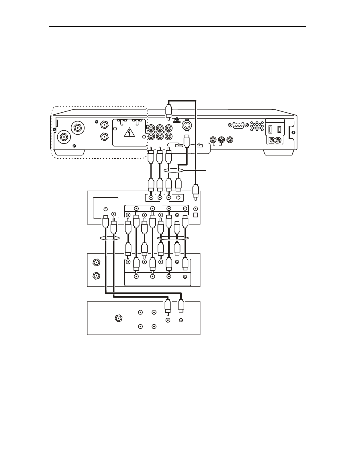
Installation 3333----17
Using this configuration the audio/video signals are passed through the digital receiver to
enable the VCR record and playback features. Figure 3-17 illustrates audio/video connections
for a Dolby Digital receiver:
Figure 3-17
Audio through Stereo Receiver
See appropriate cable diagram
17
1717
TO
TV/VCR
RF
IN
TO RF IN
CABLE IN
AUX AUDIO IN SPDIF
VIDEO
R
L
AUD IO OU T
S-VIDEO
TV Pass Card
DIGITAL
RECEIVER
Monitor
out
Video
In
Out
S-Video
Either or S-Video
VCR
AUDIO
IN
AUDIO
OUT
R
CABLE IN
CABLE OUT
In
Video 1
Video 2
Coaxial
Optical
Baseband Video
VIDEOINSVIDEO
L
L
R
VIDEO
OUT
IN
SVIDEO
OUT
HIGH OUT OF
BAND
SPEED
DATA
Either or
or
IR
SWITCHED
105 -125 V
60Hz
4A MA X
500W MA X
TV
CABLE IN
AUDIO
IN
AUDIO
OUT
LR
SVIDEO
VIDEO
IN
IN
LR
DCT 2000 Installation Manual
Page 37

3333----18
18 Installation
1818
Operational Check
The operational check tests the communication link between the remote control and the
DCT 2000. The procedures verify the DCT 2000 response to remote control commands.
Table 3-2lists the operational check procedures:
Table 3-2
Operational check
Feature Testing Procedure
Power on
Channel Selection
Volume Control
If the DCT 2000 does not operate properly, refer to Section 5, “Troubleshooting.”
§ Press POWER to turn on the DCT 2000.
§ Turn on the TV and tune it to the output channel of the DCT 2000 (channel 3 or 4).
§ Scan through the channels using the CHANNEL
keys on the remote control.
keys on the DCT 2000 and the CHANNEL + -
§ Tune to several channels by entering the channel number with the numeric keys on the remote
control.
§ Use the TV volume control to adjust the sound volume to a moderate level.
§ Press VOLUME + - on the remote control to increase the volume to its upper limit, lowest level, and
to a comfortable level.
§ Press MUTE to turn the sound completely off. Press MUTE again to restore the sound.
DCT 2000 Installation Manual
Page 38
Section 4
Adding the IR Blaster Option
The IR Blaster provides control of the subscriber’s VCR from the DCT 2000. It consists of a
low-power infrared transmitter attached to a six-foot cord and a mounting bracket. The
mounting bracket is a clear plastic holder with a pad of adhesive tape for installing the
IR Blaster near the VCR IR receiver. A mini-pin connector at the end of the cord connects the
IR Blaster to the DCT 2000.
The IR Blaster functionality is controlled by the interactive program application that is resident
on the DCT 2000. Not all applications support the optional IR Blaster.
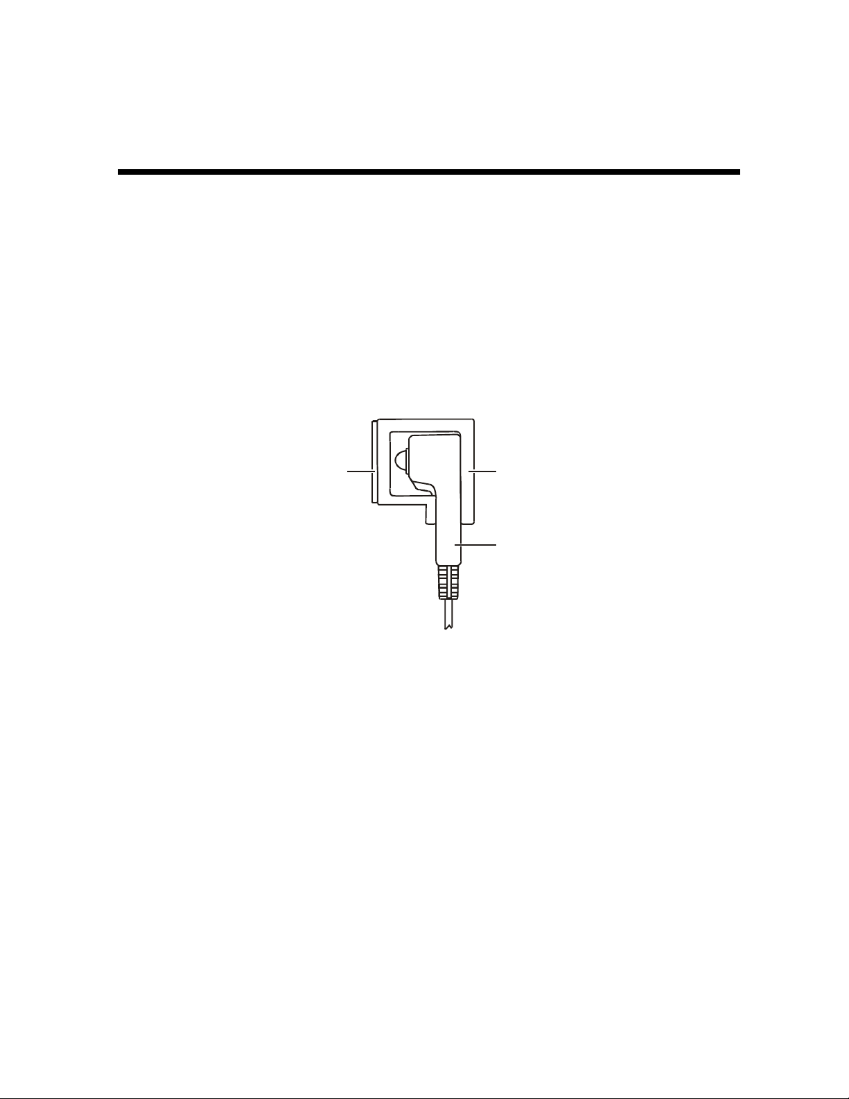
Figure 4-1 illustrates the IR transmitter installed in the mounting bracket:
Figure 4-1
IR transmitter installed in mounting bracket
Adhesive tape
The IR Blaster is automatically activated through the electronic program guide. Individual
VCR codes are broadcast through the out-of-band data channel and are updated periodically as
new codes are added.
The procedure for installing the IR Blaster is described in the following paragraphs.
Mounting brack et
Transmitter
Locating the IR Receiver on the VCR
The IR receiver is not visible on some VCRs. You can locate the receiver using the following
procedure:
1 Obtain a piece of opaque material, such as a 3- by 5-inch index card.
2 Use the card to block areas of the VCR where the receiver might be located. Turn the VCR
on and off, while pointing the remote control at the card blocking the VCR. Be sure the
remote control is close to the VCR to reduce reflections the receiver may pick up.
3 Note the area where the VCR is unresponsive to the remote control. Thisregion contains
the receiver and can be marked by loosely taping the index card to the area.
Because the IR Blaster radiates an area approximately 40 degrees wide, it is not necessary to
be precisely on target with the remote control. Offset the location of the IR Blaster transmitters
from the VCR receiver to reduce interference with operation of the VCR remote control.
DCT 2000 Installation Manual
Page 39
4444----2222 Adding the IR Blaster Option
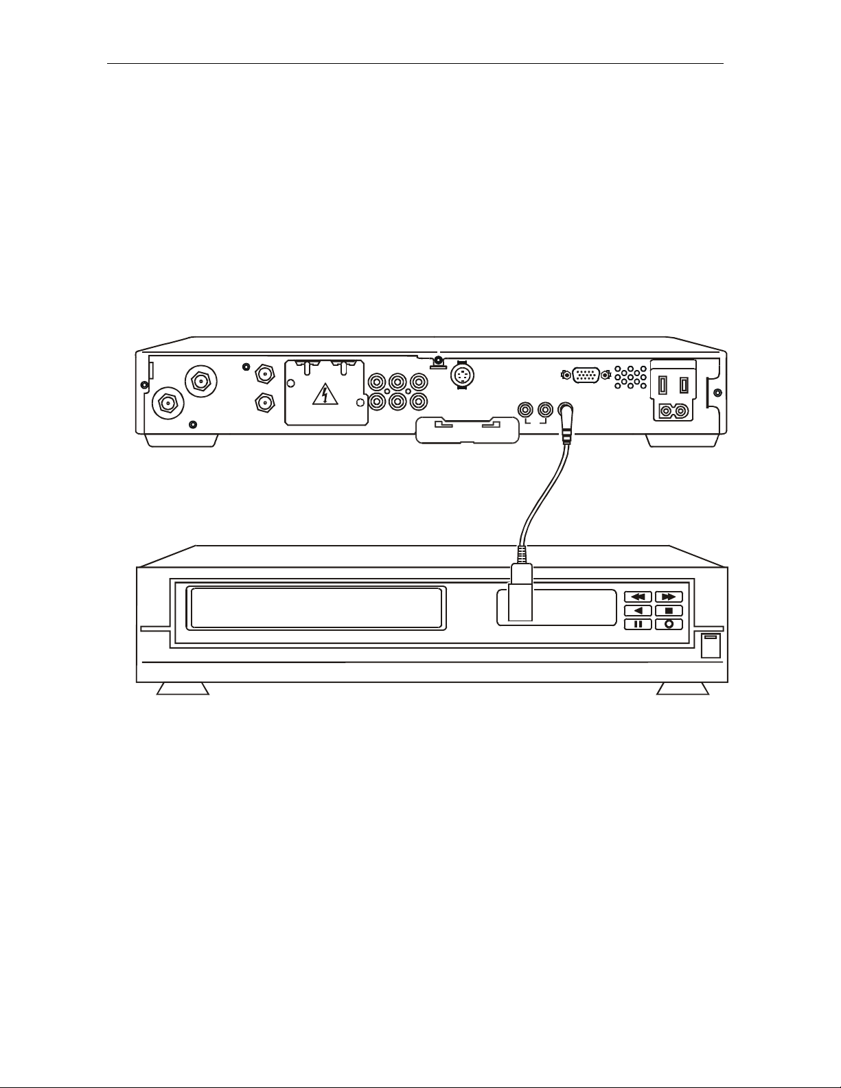
Installing the IR Blaster
To install the IR Blaster:
1 Fit the transmitter into the mounting bracket (refer to Figure 4-1).
2 Plug the mini-pin connector into the IR jack on the rear panel of the DCT 2000 rear panel
(refer to Figure 4-2).
Figure 4-2
IR Blaster installed
DCT 2000
TO
TV/VCR
RF
IN
TO RF IN
CABLE IN
AUX AUDIO IN SPDIF
VIDEO
R
L
AUD IO OU T
S-VIDEO
TV Pass Card
VCR
3 Remove the adhesive tape cover from the mounting bracket.
HIGH OUT OF
SPEED
DATA
IR
BAND
SWITCHED
105 -125 V
60Hz
4A MA X
500W MA X
4 Position the IR receiver off center of the VCR receiver and then press firmly attaching the
mounting bracket on the VCR. Be careful to route the wire so that it does not prevent
loading videotapes.
Checking the Installation
The IR Blaster is now located near the receiver and the VCR can be controlled through the
DCT 2000. As a final check, operate the VCR using the remote control from various positions in
the room. If the IR Blaster is obstructing the IR receiver on the VCR, move it slightly.
DCT 2000 Installation Manual
Page 40

Section 5
Troubleshooting
This section provides information to assist you in quickly detecting, isolating, and resolving
error conditions that might occur when using the DCT 2000. If you need assistance, call TRC at
1-888-944-HELP (1-888-944-4357).
Table 5-1 is a list of possible problems and solutions:
Table 5-1
Troubleshooting guidelines
Problem Possible Solution
No power to the DCT 2000
Check the power outlet for AC power.
Be sure the TV is tuned to the output channel of the DCT 2000 (channel 3 or 4).
Verify that cable connections are correct from the TV set or monitor to the DCT 2000.
Check that the power cord is properly plugged into the outlet and DCT 2000.
Remote control is not
responding
The DCT 2000 is not
receiving a cable signal
Guide has no data
VCR did not record
Check for an obstruction between the remote control and the DCT 2000. Aim the remote control
directly at the DCT 2000, not the TV or VCR.
Be sure you firmly and deliberately press and release operation keys one at a time.
Verify that channels can be changed using the keys on the front panel and then check that the
batteries have been installed properly. Replace with new batteries if necessary.
Check that the DCT 2000 has been initialized correctly, refer to Diagnostics.
Check the cable connections and hand-tighten if necessary.
Verify that the cable connections are correct.
Verify the TV is working and has a clear picture.
Unplug the power to the DCT 2000 and plug in the unit again. Wait for the DCT 2000 to collect
the data.
Turn the VCR off when you are not using it.
Be sure the IR Blaster is correctly placed.
Check the Scheduled Events list to be sure programs are scheduled for recording.
DCT 2000 Installation Manual
Page 41

Appendix A
Specifications
Input frequency
HRC/IRC frequency assignments
Number of channels
Analog
Digital
Dual A/B cable switching
Input analog video level
Input analog sound level
Average digital input level
Data carrier
Frequency
Bandwidth
Level
Video s/n
Output frequency accuracy
Return loss
Input
54 through 860 MHz (excluding data carrier frequency)
Downloadable
136 carriers per cable, 1 or 2 cables
1 channel per carrier
More than 1 channel per carrier, content dependent
Optional A/B (field upgradeable)
0 dBmV through +15 dBmV
–17 dBmV through +2 dBmV
–10 dBmV through +5 dBmV
QPSK-modulated carrier
75.250 MHz or 72.75 MHz or 104.2 MHz
1.5 MHz
–10 dBmV through +5 dBmV
49 dB @ 0 dBmV input level
150 kHz
±
6 dB minimum
Output
Spurious output
Cross-modulation distortion
Composite second order distortion
Second order distortion
Composite triple beat distortion
Set-top input beats (with all input signals)
Hum modulation distortion
Output level
Isolation (input/output)
Differential phase
Analog descrambling method (optional)
On-screen display (OSD)
Screen size
Message/barker capacity
Mechanical security
8 dB minimum
–57 dBc maximum, in band
–56 dB (136 channels, each @ +15 dBmV)
–57 dB (136 channels, each @ +15 dBmV)
–60 dB (136 channels, each @ +15 dBmV)
–57 dB (136 channels, each @ +15 dBmV)
–25 dB (136 channels, each @ +15 dBmV)
3 IRE
10 through 15 dBmV
70 dB minimum
10 degrees (maximum)
Gated sync suppression or dynamic gated sync suppression, video inversion, audio
privacy, and Hamlin compatibility
352 x 480 pixels (configuration dependent)
Up to 40 pages (configuration dependent)
Standard: security screws, unichassis construction
DCT 2000 Installation Manual
Page 42

AAAA----2222 Specifications
Operating environment range
Temperature
Humidity
ac voltage
Power dissipation
Surge protection
Size
Weight
0° through 40°C (32° through 104°F)
5 through 95% (noncondensing)
105 through 125, 60 Hz
35 W at 115 Vac
Provided on power supply and RF ports
17.13 × 13.25 × 2.75 inches
8.6 pounds
DCT 2000 Installation Manual
Page 43

Appendix B
Diagnostics
This section describes the diagnostics designed to confirm proper installation of the DCT 2000.
The diagnostics include checking error states and signal integrity, as well as provisions to
identify the DCT 2000 on the network and to verify communications with the headend. The
diagnostic information is displayed on the front-panel LEDs and the On-Screen-Display.
For diagnostics provided in this appendix:
All indicators are in decimal notation unless otherwise noted.
§
All signal-level and quality indicators are based on a 0 to 100% scale, unless otherwise
§
noted.
All screens self-refresh at a minimum rate of once every five seconds.
§
All sample displays are illustrative; actual data will differ from the examples.
§
Accessing Diagnostics
To access the DCT 2000 diagnostic mode:
1 Press POWER to turn on the DCT 2000.
2 Wait five seconds.
3 Press POWER to turn off the DCT 2000.
4 Press SELECT within two seconds. The DIAGNOSTICS Main menu (Figure B-1) is displayed
on the OSD and
diagnostic mode.
5 Use the CHANNEL
6 Press CURSOR <, CURSOR >, SELECT,orENTER to execute the selected diagnostic.
7 To exit the diagnostic mode, press POWER. The DCT 2000 exits the diagnostic mode and
powers off.
is displayed on the front-panel LEDs. The DCT 2000 is now in
d01
keys to select the desired diagnostic.
DCT 2000 Installation Manual
Page 44

BBBB----2222 Diagnostics
Navigating the Diagnostics
Figure B-1 illustrates the OSD DIAGNOSTICS Main menu:
Figure B-1
DIAGNOSTICS Main menu − OSD
DIAGNOSTICS
01 GENERAL STATUS
02 OOB STATUS
03 IN BAND STATUS
04 IN BAND ERROR
05 UNIT ADDRESS
06 FIRMWARE VERSION
07 CURR CHANNEL STAT
08 RENEWABLE SECURITY
09 UPSTREAM MODEM
10 APP CODE MODULES
11 MEMORY CONFIG
12 KEYBOARD/LED
13
14
Table B-1 provides a list of keys and key functions for selecting diagnostics:
INTERACTIVE INFO (Available only on firmware
v 06.x)
MAC FREQ TABLE (Available only on firmware v
0.6.x)
Table B-1
Operational keys using the DIAGNOSTICS Main menu or submenus
Key Key function using the DIAGNOSTICS
Key function using a diagnostic
Main menu
POWER
CH/CUR +,
CURSOR UP
CH/CUR - ,
CURSOR DOWN
CURSOR RIGHT,
CURSOR LEFT,
SELECT,
ENTER
INFO,
GUIDE
DCT 2000 exits the diagnostic mode and enters the
OFF state
Moves the cursor up Displays the DIAGNOSTICS Main menu
Moves the cursor down Displays the DIAGNOSTICS Main menu
The DCT 2000 executes the selected diagnostic Displays the DIAGNOSTICS Main menu
No function No function
DCT 2000 exits the diagnostic mode and enters the
Off state
DCT 2000 Installation Manual
Page 45

Diagnostics BBBB----3333
Table B-2 lists the LED and provides a description of each diagnostic. It also indicates whether
the diagnostic provides information on the LED/OSD:
Table B-2
Diagnostic
LED Diagnostic LED OSD
d 01
General status of the DCT 2000 X X
d 02
d 03
d 04
d 05
d 06
d 07
d 08
d 09
d 10
d 11
d 12
d-13
d 14
QPSK out-of-band receiver status X X
In-band receiver status X X
In-band error count X X
Unit address X X
Firmware version X X
Channel status X X
Renewable security system X X
Upstream modem status X X
Application code modules X X
Memory configuration X
Keyboard and LED diagnostic X X
Interactive info X
MAC frequency table X X
DCT 2000 Installation Manual
Page 46

BBBB----4444 Diagnostics
y
d 01: DCT 2000 General Status
This diagnostic indicates the general status of the DCT 2000. Figure B-2 illustrates the LEDs,
which alternate between the error code and the purchases count:
Figure B-2
DCT 2000 general status − LEDs
Error displa
P
MUTE
alternating with purchases count
and IPPV status indicator
P
MUTE
IPPV
status indicator
The purchases count is used by Customer Service Representatives (CSRs) to check returned
DCT 2000 for uncollected purchases, that are used to close out a subscriber’s account. The
largesterror code takes priority.
Figure B-3 illustrates the DCT 2000 STATUS OSD, which displays the error code, a short
description of the error, the purchases count, and specific model information:
Figure B-3
DCT 2000 STATUS − OSD
DCT 2000 STATUS
ERROR: E 00
NO ERROR
PURCHASES 10
Platform ID:
Family ID:
Model ID:
TUNER: V860
Remod Channel: 3
DCT 2000 Installation Manual
Page 47

Diagnostics BBBB----5555
Table B-3 lists the error codes:
Table B-3
Error codes
Initialization status errors
Error Code OSD Cause Remedy
E 00*
NO ERROR Indicates normal condition after initialization Not applicable
E 01*
E 02
E 03
E 04
E 07
E 08
E 09
E 10
E 11
E 12
E 13
NOT CONNECTED DCT 2000 did not receive a connect message Send a connect message
Restore out-of-band signal
PWR CYCLE Init Error Box needs a Power Cycle to
recover
DRAM DRAM error Not used at this time
DPSRAM DP-SRAM error Not used at this time
ROM ROM verification failure Power cycle box; if repetitive,
return for repair
RAM Faulty RAM, ROM, EEPROM, or POST failure
(this is a hardware failure)
BATTERY Dead battery or memory has not been
initialized; occurs if battery fails to keep the
RAM alive during power-down; causes
DCT 2000 to be disconnected
SERIALNO Invalid serial number Not used at this time
UNIT ADDRESS Invalid unit address Return DCT 2000 for repair;
POST POST failed Not used at this time
BOOT Sys_boot initialization failure Power cycle box; if repetitive,
Return DCT 2000 for repair
Return DCT 2000 for repair;
requires factory initialization
message
requires a unit creation message
return for repair
E 14
E 15
E 16
E 17
STARTUP DCT 2000 system startup failure Power cycle box; if repetitive,
return for repair
TSI INVALID TSI structure is corrupted Power cycle box; if repetitive,
return for repair
FLASH BAD NUMBER Bad flash number specified for
InitiateFlashPlatform
BAD PLATVAL Bad platform validation step number Error logged, ignore
Error logged, ignore
*E 00 and E 01 cannot be displayed while the DCT 2000 is off. The other errors will display on
the LEDs when the DCT 2000 is off.
DCT 2000 Installation Manual
Page 48
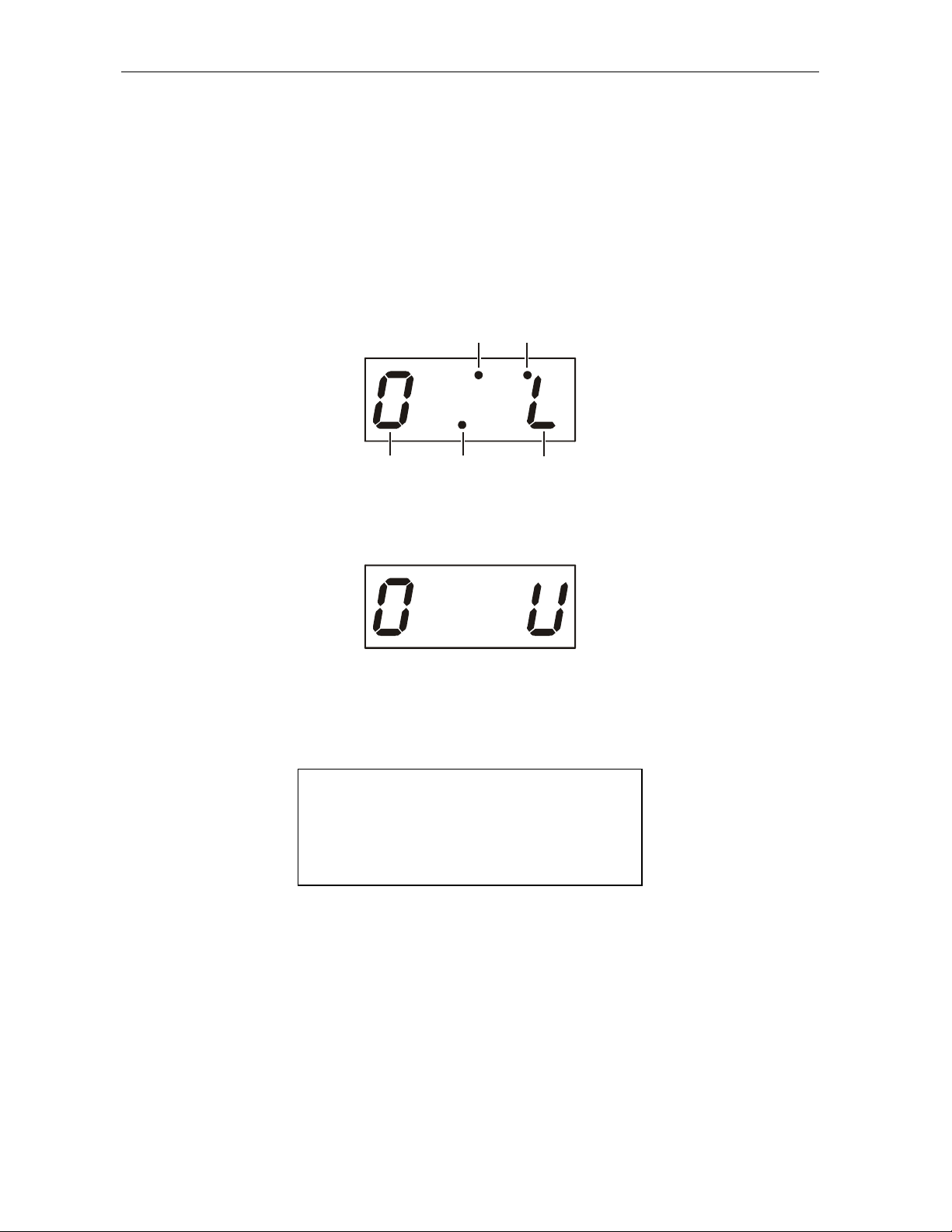
BBBB----6666 Diagnostics
d 02: Out-of-Band Receiver Status
This diagnostic indicates the status of the out-of-band control channel. Figure B-4 illustrates
the out-of-band status LED display:
Figure B-4
Out-of-band status − LEDs
EMM
Data
activity
MUTE MUTE
data
activity
P
Out-of-band
diagnostic
indicator
MUTE MUTE
PID 1
received
Indicates no data
Carrier
lock
P
Figure B-5 illustrates the OOB DIAGNOSTIC (out-of-band status) OSD:
Figure B-5
OOB DIAGNOSTIC (out-of-band status) − OSD
OOB DIAGNOSTIC
DATA *
EMM DATA *
CARRIER LOCK YES
Table B-4 lists the LED and OSD indications of whether the out-of-band receiver is locked to
the carrier (this indicator can falsely indicate locked):
Table B-4
LED and OSD indicators for out-of-band receiver state
LED OSD State
L
U
DCT 2000 Installation Manual
YES Carrier locked
NO Carrier unlocked
Page 49

Diagnostics BBBB----7777
Data Activity and EMM Data Activity Indicators
The LED EMM Data Activity indicator is lit when a message is present and the Data Activity
indicator shows receipt of a message. The OSD indicates with a *, that data has been received.
The indicators cover all packet processors regardless of which stream they are monitoring and
are cleared when you enter the diagnostic.
Table B-5 lists how the EMM data activity indicator shows when the DCT 2000 is receiving a
message on the EMM stream:
Table B-5
Out-of-band EMM data activity indicator − LED and OSD
LED OSD Status
off
Blank No data received
on
* Data received
The DCT 2000 can receive only six PIDs at one time. Data on PIDs can be present on the
out-of-band multiplex that the DCT 2000 is not receiving.
DCT 2000 Installation Manual
Page 50
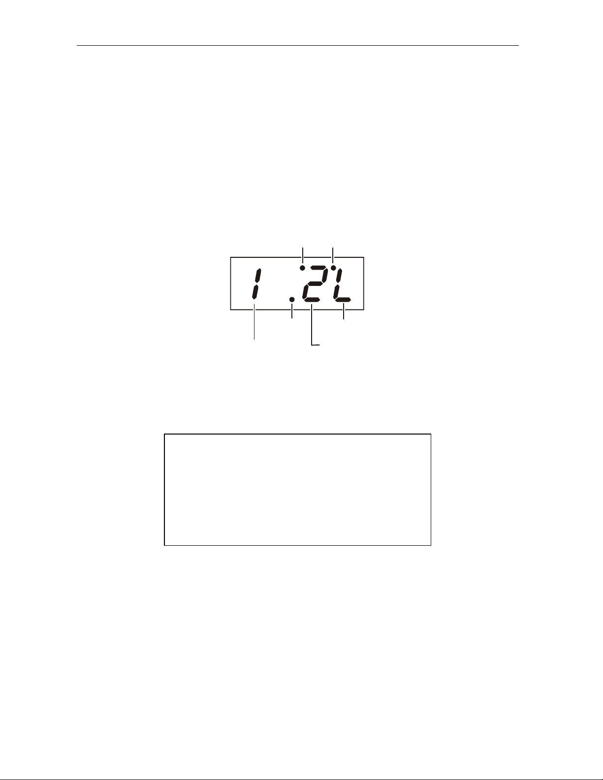
BBBB----8888 Diagnostics
M
d 03: In-Band Receiver Status
The DCT 2000 displays the in-band diagnostics for the last attempted channel tune. If a digital
carrier is not present, the diagnostics indicate the carrier lock is analog. When the carrier lock
is analog, all fields for digital, other than a carrier lock channel, are blank.
Figure B-6 illustrates the in-band receiver status as shown on the LED:
Figure B-6
In-band receiver digital status − LED
EM
Data
activity
MUTE MUTE
data
activity
P
PCR
lock
IB diagnostic
indicator
Carrier lock
Modulation
mode
Figure B-7 illustrates the IN-BAND DIAGNOSTIC (in-band receiver digital status) OSD:
Figure B-7
IN-BAND DIAGNOSTIC (in-band receiver digital status) − OSD
IN-BAND DIAGNOSTIC
DATA *
EMM DATA *
CARRIER LOCK YES
PCR LOCK YES
SNR 47
AGC 23
ssss
ssss
DCT 2000 Installation Manual
Page 51

Diagnostics BBBB----9999
In-Band Data Activity Indicator − LED and OSD
The in-band data activity indicator lights when the DCT 2000 is receiving a message. The
indicator is blank when you enter this diagnostic and three seconds after receiving the last
message. The indicator covers all packet processors regardless of which stream they are
monitoring.
Table B-6 lists the LED and OSD indications:
Table B-6
In-band data activity
LED OSD Status
off
blank No data received
on
* Data received
EMM Data Activity Indicator − LED and OSD
Table B-7 lists the LED and OSD indicator lights when the DCT 2000 is receiving a message on
the EMM stream. The indicator is clear when entering this diagnostic.
Table B-7
EMM data activity indicator − LED and OSD
LED OSD Status
off
on
blank No data received
* Data received
Carrier Lock − LED and OSD
This diagnostic indicates that the digital in-band receiver is locked to thecarrier.
Table B-8 lists the LED and OSD indications:
Table B-8
In-band carrier lock − LED and OSD
LED OSD Status
L
YES Carrier locked
U
A
NO Carrier unlocked
Analog Analog channel
DCT 2000 Installation Manual
Page 52

BBBB----10
10 Diagnostics
1010
PCR Lock − OSD Only
The PCR lock indicates a program-clock-reference lock with the current digital datastream.
Signal-To-Noise Ratio (SNR) and Automatic Gain Control (AGC) − OSD Only
The SNR displayed on the OSD is a rough estimate of the carrier signal-to-noise ratio. The
SNR displayed is a measure of the QAM cluster variance, which is proportional to the
signal-to-noise ratio.
The AGC value roughly indicates the received signal level.
Analog channels display
analog
for carrier lock. The SNR and AGC display a number for the
numeric value and blank for the ssss value. A blank display indicates that the digital section of
the DCT 2000 is still in the initial state. If this occurs, check diagnostic d07.
Table B-9 lists the SNR and AGC indicators for the OSD:
Table B-9
SNR and AGC indicators − OSD only
ssss value Meaning
GOOD
FAIR
BAD
Good value
Marginal signal level − check the signal
Unusable signal
d 04: In Band Error
The error count representsthe number of uncorrectable errors in the digital multiplex. The
QAM receiver must be locked to the signal before errors can be detected. A four-digit value of
0000 displayed on the LED indicates that there are no uncorrectable errors. The display shows
the short-term error count and is updated every five seconds. The maximum count is 9999.
The long-term error count is a sum of the errors occurring over the last 24 hours of DCT 2000
operation. This data is maintained between channel changes and power cycles. This count is
reset every 24 hours of DCT 2000 operation. The maximum is 9999 counts.
Figure B-8 shows the receiver status error count on the LEDs:
Figure B-8
In-band receiver status error count short term LEDs
P
MUTE
When there is no carrier lock, the LEDs display four dashes (
DCT 2000 Installation Manual
−−−−
).
Page 53

Figure B-9 shows the receiver status error count on the OSD:
Figure B-9
In-band receiver status error count short term OSD
IN-BAND RCVR STATUS
SHORT-TERM ERROR COUNT
3456
LONG TERM ERROR COUNT
7890
Diagnostics BBBB----11
11
1111
When there is no carrier lock, the error count displays four dashes (
−−−−
).
d 05: Unit Address
This diagnostic displays the 16-digit (40-bit) unit address of the DCT 2000. It displays in five
parts on the four-section LED. The address display stays on each section for five seconds. The
location of the dash in each of the five displays is unique. Figure B-10 shows the LEDs for unit
address 123-45678-90123-456:
Figure B-10
Unit address LEDs
P
MUTE
P
MUTE
P
MUTE
MUTE
MUTE
P
P
DCT 2000 Installation Manual
Page 54

BBBB----12
12 Diagnostics
1212
On the unit address OSD, the unit, network, and TV PassCard (TvPC) addresses are in decimal
form (13 address digitsand three check digits). The multicast 16-bit addressis in TCP/IP
decimal byte form. Figure B-11 illustrates the unit address OSD:
Figure B-11
Unit address OSD
DCT 2000 UNIT ADDRESS:
123-45678-90123-456
Network Address:
123-45678-90123-456
TvPC:
123-45678-90123-456
Multicast 16 Address:
255.255 255.255
255.255 255.255
nnnn
255.255 255.255
255.255 255.255
The value nnnn shown in Figure B-11 represents the following datastreams: DATA, VCN,
POLL, NET, EMM, SCC, and DWLD. The Multicast 16 address numbers change to display the
values for each datastream.
DCT 2000 Installation Manual
Page 55
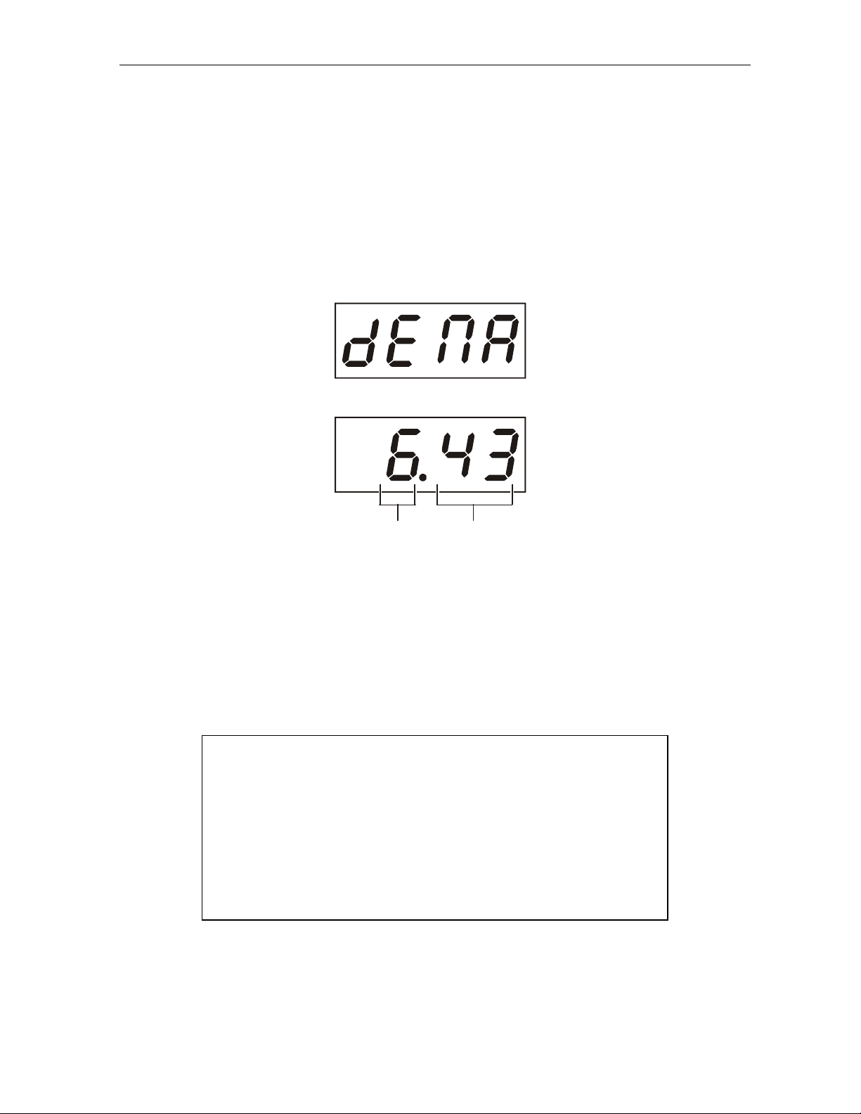
Diagnostics BBBB----13
d 06: Firmware Version
This diagnostic displays dENA firmware version 06.xx. Figure B-12 illustrates that the LEDs
alternate between displaying the firmware version number and the characters dENA:
Figure B-12
dENA firmware version LEDs
P
MUTE MUTE
Alternating with
P
13
1313
MUTE MUTE
Major
revision
number
Minor
revision
number
This menu option available only on 06.xx series firmware.
The dENA firmware version OSD displays the dENA firmware revision number, build date,
CAMEL firmware version number, and TSODA firmware version number. Figure B-13
illustrates the dENA firmware version OSD:
Figure B-13
dENA firmware version OSD
FIRMWARE VERSION
06.43
May 14, 1997
08:13:54
TSODA t14
CAMEL
8404
(appears on firmware v06.xx)
DCT 2000 Installation Manual
Page 56
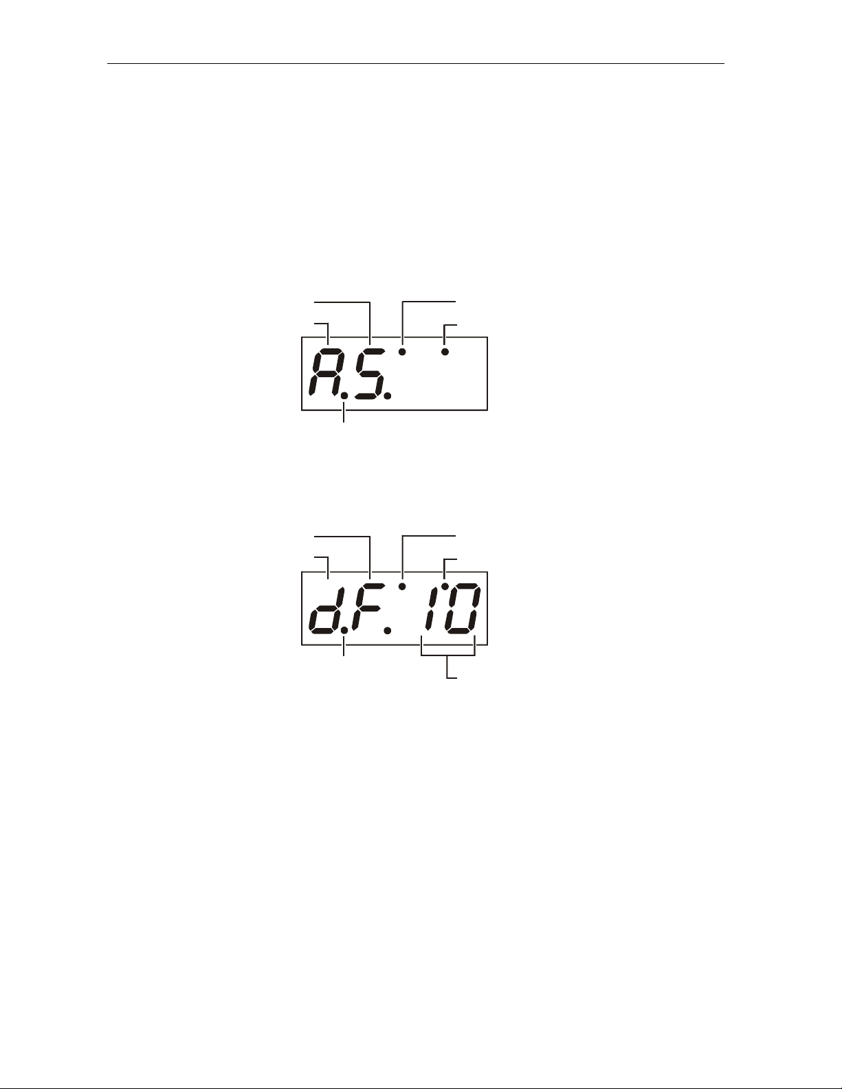
BBBB----14
e
14 Diagnostics
1414
d 07 Current-Channel Status
This diagnostic gives the instantaneous statusof the lastattempted channeltune on the
in-band tuner. The status shows channel type (analog/digital), acquisition state, purchasable
indicator, preview indicator, parental control status, and mute status. Figure B-14 illustrates a
current channel status display on the LEDs:
Figure B-14
Current channel status LEDs
Acquisition stat
Channel type
Current
channel
Analog
Acquisition state
Channel type
Current
channel
Digital
MUTE MUTE
Parental
control
status
or
MUTE MUTE
Parental
control
status
Purchasable indicator
Preview indicator
P
Purchasable indicator
Preview indicator
P
Epoch authorization reason
“dF 10” does not alternate with the virtual channel number.
LED Channel Types
TableB-10liststhepossiblechanneltypes:
Table B-10
Channel Types − LED and OSD
1st LED OSD Meaning
A
d
DCT 2000 Installation Manual
Analog Analog channel
Digital Digital channel
Page 57

Acquisition States
Table B-11 lists the acquisition states:
Table B-11
Acquisition states
2nd LED State
n
Not connected
Diagnostics BBBB----15
15
1515
I
C
A
d
S
E
U
Initialized to acquire the program
Configured to acquire the program
Acquiring the program
Not authorized for the program
Authorized for analog program
Authorized for encrypted digital program
Unencrypted digital program
Purchasable Indicator − LED and OSD
Table B-12 liststhe purchases indicator:
Table B-12
Purchasable status − LED and OSD
LED OSD Meaning
off NO
on YES
Channel is not purchasable at present
Channel is purchasable at present
Preview Indicator − LED and OSD
Table B-13 lists the preview indicator:
Table B-13
Preview status − LED and OSD
LED OSD Meaning
off NO
on YES
Channel is not in preview
Channel is in preview
DCT 2000 Installation Manual
Page 58

BBBB----16
16 Diagnostics
1616
Current Channel Status OSD
The current channel status OSD has the following fields:
The TYPE field indicates whether the current channel is analog or digital.
§
The STATUSfield indicates the current channelacquisition/authorization state.
§
The ddd CONNECTED field indicates whether the DCT 2000 is connected or disconnected.
§
If the value is connected, the program is viewable.
The PARENT CONTROL field indicates whether the current channel is parentally
§
controlled.
The PURCHASABLE field indicates that the program can be purchased.
§
The PURCHASED field indicates that the program has been bought.
§
The PREVIEW field indicates that the program is in the free preview state.
§
Figure B-15 illustrates the current channel status display for analog channels on the OSD:
Figure B-15
CURRENT CHANNEL STATUS OSD for analog channel
CURRENT CHANNEL STATUS
TYPE ANALOG
STATUS ccccc
ddd CONNECTED
PARENT CONTROL YES
PURCHASABLE YES
PURCHASED YES
PREVIEW YES
Figure B-16 illustrates the current channel status display for digital channels on the OSD:
Figure B-16
Current channel status OSD for digital channel
CURRENT CHANNEL STATUS
TYPE DIGITAL aaa bb
STATUS ccccc
ddd CONNECTED
PARENT CONTROL YES
PURCHASABLE YES
PURCHASED YES
PREVIEW YES
DCT 2000 Installation Manual
Page 59

Current channel status − OSD fields
Table B-14 lists the current channel status OSD fields:
Table B-14
Current channel status − OSD fields
Diagnostics BBBB----17
17
1717
OSD
variables
aaa
bb
State
Analog − blank
For digital only:
n ENC
n UNE
current epoch authorization reason in the
current_epoch_auth_reason field. This is displayed in hex:
00 – missing program re-key
01 – missing working key epoch message
02 – missing event blackout message
03 – missing category rekey
04 – old category sequence in program, rekey message
10 – program bought
11 – program bought without taping
12 – subscribed with taping
13 – subscribed without taping
14 - subscribed with taping purchasable
15 – IPPV with taping
16 – IPPV without taping
20 – bad seed checksum
21 – bad debit buffer checksum
30 – IPPV not enabled
31 – insufficient credit to purchase
32 – show count limit exceeded
33 – debit register will overflow
34 – no AFP records available
36 – maximum package cost exceeded
37 – no IPPV overlay in message
40 – not subscribed
41 – regional blackout
42 – event blackout
encrypted
−
unencrypted
−
ccccc
ddd
INIT − Initialized state
CONFI − Configured
ACQUI − Acquiring the program
AUTH − Authorized for the program
Not A − Not authorized for the program
blank − Connected
NOT − Not connected
DCT 2000 Installation Manual
Page 60

BBBB----18
18 Diagnostics
1818
d 08: Renewable Security System
The renewable security systemincludes a TvPC card that returns the security status to
current. The statusLED includes whether the TvPC is required, the mode, status, and version.
Figure B-17 illustrates the renewable security status LEDs:
Figure B-17
Renewable security status LEDs
TvPC
status
P
TvPC
status
Crypto
TvPC
mode
MUTE MUTE
Alternating with
TvPC
Revision
MUTE MUTE
Figure B-18 illustrates the RENEWABLE SECURITY OSD:
Figure B-18
RENEWABLE SECURITY − OSD
RENEWABLE SECURITY
SYSTEM STATUS
TvPC NOT REQUIRED
CRYPTO: STAND ALONE
STATUS: 00
VERSION: 00
P
DCT 2000 Installation Manual
Page 61

Diagnostics BBBB----19
TvPC Required − LED and OSD
Table B-15 shows how the LED and OSD indicate whether further operation of the DCT 2000
requiresthe TvPC:
Table B-15
TvPC required
LED OSD Status
n
NOT REQUIRED TvPC not required
19
1919
Y
IS REQUIRED TvPC is required
Current Mode
Table B-16 lists the current mode as displayed on the LED and the OSD:
Table B-16
Current mode
LED OSD Status
A
S
n
STAND ALONE Stand alone
SUPPORT Support
NOT MATED Not mated
TvPC Status
Table B-17 shows the TvPC status as displayed on the LEDs and the OSD:
Table B-17
TvPC status
LEDs and
Status
OSD
00
OK
01
02
03
04
05
0a
0b
0C
0d
TvPC communication problem
TvPC required
Validator does not match between GK and TvPC
Invalid unit key number
Old TvPC unit address
TvPC not mated
TvPC/base module unit address mismatch
New TvPC, but wrong version number
TvPC unit address mismatch
DCT 2000 Installation Manual
Page 62

BBBB----20
20 Diagnostics
2020
d 09: Upstream Modem Status
These diagnostics display the appropriate set of STARVUE II (RF) and STARFONE (telephone)
modem information based on the module installed in the DCT 2000.
STARVUE II (RF) Diagnostics
This diagnostic shows the status and operating parameters for the STARVUE II RF return. See
Tables B-18 and B-19 for testing the parameters. Figure B-19 illustrates the STARVUE II
diagnostics LEDs:
Figure B-19
STARVUE II diagnostics LEDs
Decimal point
P
ST ARVUE
frequency
MUTE MUTE
Transmitter
status
Alternating with
ST ARVUE
power level
MUTE MUTE
Transmitter
status
Figure B-20 illustrates the STARVUE II DIAGNOSTICS OSD:
Figure B-20
STARVUE II DIAGNOSTICS OSD
STARVUE II DIAGNOSTICS
STATUS t
FREQUENCY 9.0 MHz
LEVEL 34
IPPV DISABLED
P
The Level field indicates the approximate power value of the STARVUE II transmitter in
dBmV. The difference between the power value on the diagnostic screen and the actual power
of the STARVUE II module is±5 dBmV.
DCT 2000 Installation Manual
Page 63

Table B-18 lists the STARVUE II transmitter status:
Table B-18
STARVUE II transmitter status
LED and OSD Indicator
-
Idle
Diagnostics BBBB----21
21
2121
t
Transmitting
Table B-19 shows how the LED and OSD indicate the IPPV status:
Table B-19
STARVUE II IPPV status
LED OSD Mode
on
flashing
off
ENABLED IPPV enabled
UNSENT
−
##
The DCT 2000 contains unsent IPPV transactions
DISABLED IPPV disabled
The variable−## is the number of unsent transactions.
STARFONE Diagnostics
This diagnostic shows the status and operating parameters for the STARFONE module.
Figure B-21 illustrate the STARFONE diagnostics LEDs:
Figure B-21
STARFONE diagnostics LEDs
Baud rate indicatorHang-up code
Transmitter status
P
Parameter status
ST ARFONE
Status
MUTE MUTE
Parental
control
Carrier
present
DCT 2000 Installation Manual
Page 64

BBBB----22
22 Diagnostics
2222
Figure B-22 illustrates the STARFONE DIAGNOSTICS OSD:
Figure B-22
STARFONE DIAGNOSTICS OSD
STARFONE DIAGNOSTICS
MODEM TYPE : 14400 BAUD
PARAMETERS : Not Verified
BAUD RATE : 300
DATA FRMT : 8, EVEN
PHONE #1 : 6
PHONE #2 : 7
BUSY COUNT : 0
NO ANSWER COUNT : 0
LOST CARRIER COUNT : 0
CARRIER:
STAUS: HANGUP-NORMAL
Table B-20 lists the STARFONE transmitter status:
Table B-20
STARFONE transmitter status
1st Digit 2nd Digit Meaning
h*
t–
d–
A–
cr
ct
c–
r*
On hook (* = hang-up code)
Test for line available
Dialing
Waiting for answer
Communicating, receiving
Communicating, transmitting
Communicating, idle
Waiting for retry (* = hang-up code)
DCT 2000 Installation Manual
Page 65

Table B-21 lists the STARFONE hang-up code:
Table B-21
STARFONE hang-up code
Mode Status
–
Normal hang-up
Diagnostics BBBB----23
23
2323
A
r
c
L
E
U
P
t
C
Answer time-out
Phone ringing
Carrier loss
Line in use
Errors (data)
User line request
Parameters invalid
Data timeout
Communication protocol fault
Table B-22 lists the IPPV status indicator:
Table B-22
STARFONE IPPV status
LED OSD Mode
on ENABLED
flashing UNSENT
off DISABLED
IPPV enabled
This DCT 2000 contains unsent IPPV transactions
IPPV disabled
Table B-23 lists the STARFONE third-digit baud rate:
Table B-23
STARFONE third-digit baud rate
LED OSD Mode
3 300
300 Baud
Table B-24 lists the STARFONE fourth-digit telephone parameters:
Table B-24
STARFONE fourth-digit telephone parameters
LED OSD Mode
— NOT SET
P (flashing) NOT VALID
P (solid) SET
Telephone parameters not set
Telephone parameters not valid
Telephone parameters OK
DCT 2000 Installation Manual
Page 66
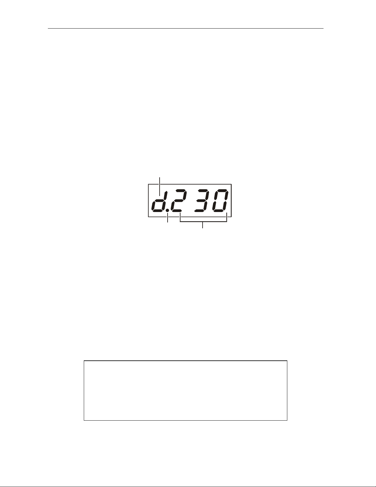
BBBB----24
24 Diagnostics
2424
d 10: Application Code Modules
This diagnostic displays the currently downloaded code modules. This can be a multi-page
display. Press
The LED diagnostic indicatesthe current download status. The data received indicator lights
when downloaded data is received. The download packet counter counts down toward zero,
indicating the remaining packets of the current module to be received. This counter will
initially be blank, and after segment zero is received it shows the remaining packets. The data
received indicator can be lit even if no additional packets are stored.
Figures B-23 and B-24 illustrate the application code module for LEDs and OSDs:
Figure B-23
Application code module LEDs
SELECT to display additional pages. The LEDs show the downloaded status.
Receiving status
P
MUTE MUTE
Carrier
lock
Number
of packet sto
be downloaded
TableB-25liststhemodeforthefirstLEDthatindicatesthecurrentstatusofthedownload:
Table B-25
First LED indicating current status of download
First LED Mode
I
C
d
Figure B-24
APP. (application) CODE MODULES OSD
Idle − no download in progress
Connected to download PID − awaiting data
Download in progress
APP. CODE MODULES
MODULE VER STATUS
DCT_ROM 01.00 DISABLD
dct_plat 01.00 ENABLED
appl_____ 2.00 DOWNLD
DCT 2000 Installation Manual
Page 67

Diagnostics BBBB----25
d 11: Memory Status
The memory-free value is the sum of all free memory. This free memory is not necessarily in
one free block. There is no LED for this diagnostic. The formatof the OSD depends on the
installed memory types.
Figure B-25 illustrates the MEMORY STATUS OSD:
Figure B-25
MEMORY STATUS OSD
MEMORY STATUS
APPLICATION
NVMEM 384 K
DRAM 768 K
PLATFORM
25
2525
ROM 512 K
NVMEM 1024 K
DRAM 256 K
FLASH 1 M
d 12: Keyboard Diagnostics
This diagnostic is used to verify the functionality of the LEDs and front-panel keys.
This LED diagnostic indicates the currently pressed key. One segment on each row is lit
corresponding to the front-panelkey.
Figure B-26 illustrates the keyboard diagnostic OSD:
Figure B-26
Keyboard diagnostic − OSD
G<>V►IM S B - + P
Each character is highlighted while the front panel key is held. Press any key on the remote
control to exit the keyboard diagnostic and display the Main menus.
DCT 2000 Installation Manual
Page 68

BBBB----26
26 Diagnostics
2626
d 13: Interactive Info – OSD
The INTERACTIVE INFO menu is a diagnostic tool used to gather information about your
system. Figure B-27 illustrates the OSD of the INTERACTIVE INFO menu:
Figure B-27
INTERACTIVE INFO menu
INTERACTIVE INFO
IP: 0.0.0.0
UPM: 0X000000
UPSTREAM ID: 0X0000
DOWNSTREAM ID: 0X0000
STATE: UNCONFIG
MAC ABORT CNTR: 0000
GOOD PACKETS:
ERROR PACKETS:
SOCKET PORT STATE
0 UNUSED
1 UNUSED
2 UNUSED
3 UNUSED
4 UNUSED
d 14: MAC Frequency - OSD
The DCT 2000 uses a range of frequencies set by the host for upstream communications.
Figure B-28 is an example of the OSD MAC FREQUENCY TABLE that will display your
frequency and power wattage:
Figure B-28
MAC FREQUENCY TABLE
MAC FREQUENCY TABLE
FREQ POWER
DCT 2000 Installation Manual
Page 69

Abbreviations and Acronyms
CSR
DCT 2000
EMM
HRC
IPG
IPPV
IR Blaster
IRC
MPAA
NVOD
NVRAM
OSD
PCR
PID
PPV
QAM
QPSK
Customer Service Representative
Digital Consumer Terminal 2000
entitlement management message(s)
harmonically related carriers
interactive program guide
Impulse Pay-Per-View
Infrared Blaster
incrementally related carriers
Motion Picture Advisory Association
Near Video on Demand
Non-volatile random-access memory
on-screen display
program clock reference
packet identifier
Pay-Per-View
quadrature amplitude modulation
quadrature phase shift keying
RSA
TCP/IP
TRC
TvPC
VOD
Return for Service Authorization
Transmission Control Protocol/Internet Protocol
Technical Response Center
TV PassCard
Video on Demand
DCT 2000 Installation Manual
Page 70

02/00
469714-001-99
 Loading...