

Page 1
DOCKCONTROLLER
DC-200
QUICKSTART GUIDE
Page 2

TABLE OF CONTENTS
INTRODUCTION 3
CONNECTING YOUR DOCKCONTROLLER DC-200 5
OPERATING MODES 7
DOCKCONTROLLER LEDS 8
DOCKCONTROLLER DRILLING TEMPLATE 9
LED BEHAVIOUR 10
CONFIGURING YOUR DOCKCONTROLLER DC-200 USING A USB MASS STORAGE DEVICE 11
CONFIGURING TOUCH ASSIGN 12
RFID READER RF-220 TROUBLESHOOTING 13
UPGRADING YOUR DC-200 FIRMWARE 14
REGULATORY INFORMATION 15
QUICKSTART GUIDE | DOCKCONTROLLER DC-200 2
Page 3
INTRODUCTION
The DockController DC-200 is a core building block when rolling out VB or VT series body-worn camera deployments to any scale.
The DC-200 is a VB or VT series body-worn camera network aggregator, which enables deployment and download management for up to 6 7-Port /
14-Port Docks, or 4 1-Port Docks of VB or VT series body-worn cameras per unit.
A Motorola Solutions RFID reader connected to a DockController will allow for Touch Assignment of VB or VT series body-worn cameras, using RFID
tags already used by operators or supplied by Motorola Solutions.
This means that the assignment of cameras becomes a one-step process with no need for users to have access to the VideoManager user interface.
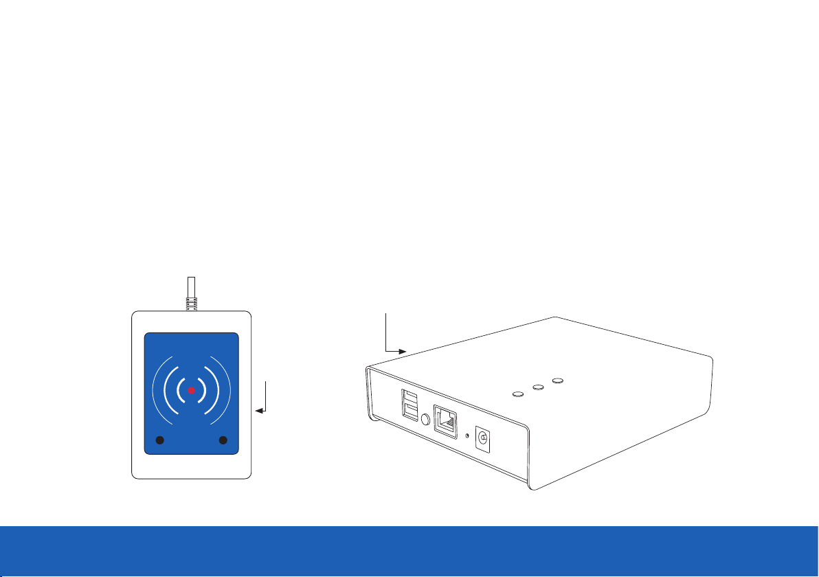
DockController
DC-200
RFID Reader
RF-220
QUICKSTART GUIDE | DOCKCONTROLLER DC-200 3
Page 4
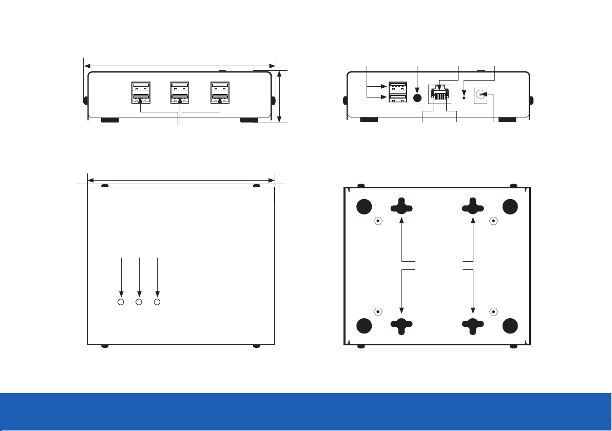
Front
135.5mm
37mm
RFID and USB
Configuration Ports
Function
Button
Back
Ethernet
Port
Reset
Button
7-Port Dock / 14-Port Dock USB Connectors
Top
154.4mm
Power
LED
A LED B LED
Link
Indicator
Activity
Indicator
Bottom
4 x Mounting Slots
Power
Port
QUICKSTART GUIDE | DOCKCONTROLLER DC-200 4
Page 5
CONNECTING YOUR
DOCKCONTROLLER DC-200
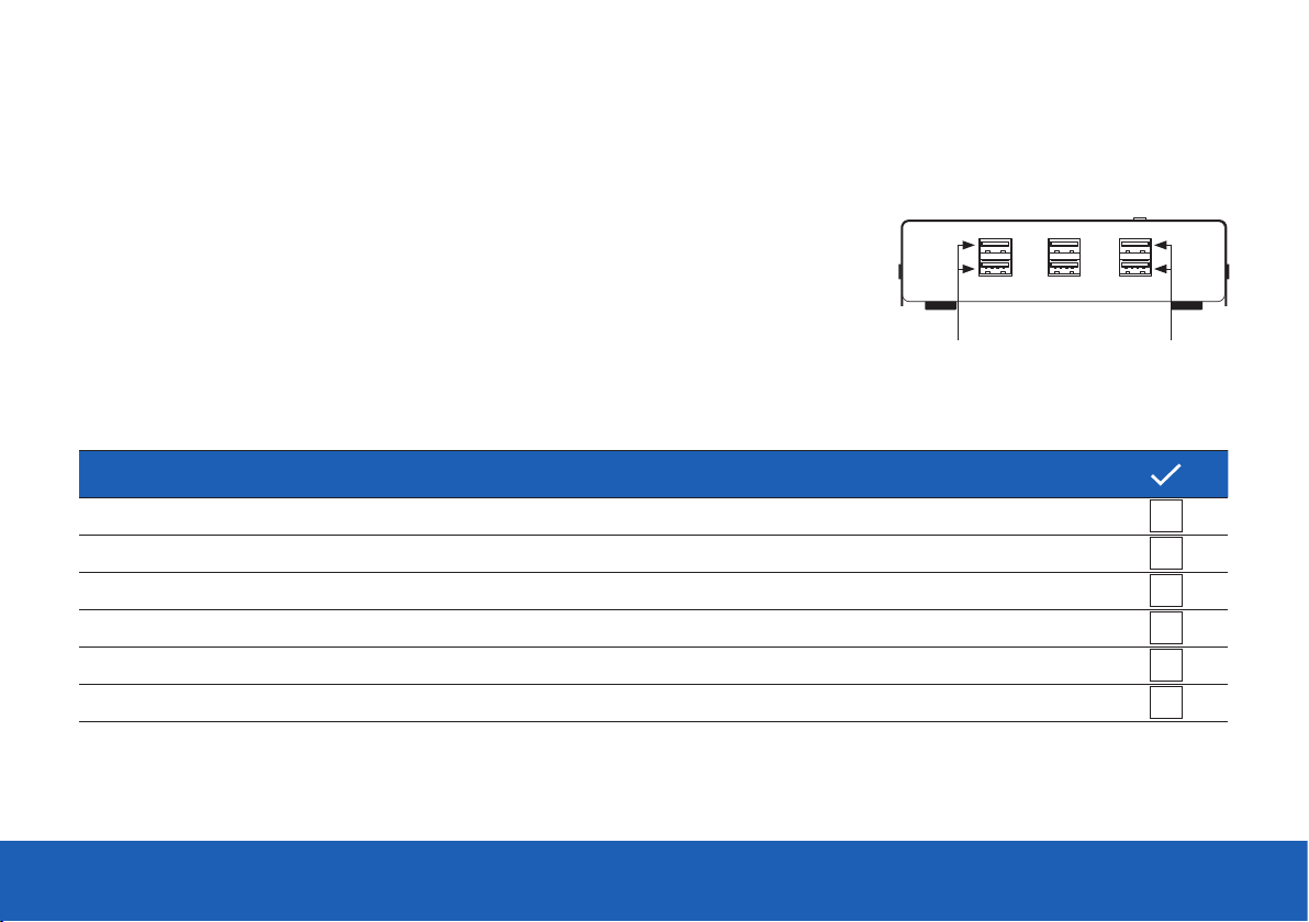
The DC-200 is very simple to connect. The six USB ports on the front of the unit should be used
for connecting the docks. The back two USB ports should only be used for USB configuration and
connecting an RFID reader. Also on the back is the Ethernet socket and the power socket,
as well as the function button and recessed factory reset button.
PLEASE NOTE: If you are not using a 7-Port or 14-Port Dock, you are restricted to connecting 4 single
VB or VT series body-worn cameras to the DockController, as it is not possible to provide sucient
power to charge a larger number of single units.
TO SET UP YOUR DOCKCONTROLLER:
Wall mount, if required. Plug your docks into the six front-facing USB ports.
Plug a cat5e Ethernet cable into the Ethernet port on back of the device.
Plug your RFID reader, if you have one, into a into USB port on the back of the DC-200.
If configuring via USB, plug in your mass storage device next to the RFID reader.
Plug the power cable into the power socket.
Turn on power at the mains.
QUICKSTART GUIDE | DOCKCONTROLLER DC-200 5
Up to 4 individual VB or VT series body-worn cameras
can be connected to the ports shown.
Page 6

Once successfully connected, the Power LED on top of the DC-200 will turn on, followed by an Ethernet Link Indicator light and then the
Ethernet Activity Indicator.
Subsequently the A LED will turn on. If the DC-200 is in Open Mode the B LED will blink slowly. If the DC-200 has been configured & successfully
connected to VideoManager the B LED will light solidly.
Link LED
Power LED
Activity LED
B LED
A LED
Back
Top
Front
Side
Bottom
QUICKSTART GUIDE | DOCKCONTROLLER DC-200 6
Page 7

OPERATING MODES
Open Mode VS Configured Mode
When initially switched on, or after a factory reset, the DC-200 will be in Open Mode, visible to every instance of VideoManager on your network.
After configuration, it will enter Configured Mode, where it is only visible to one instance of VideoManager.
QUICKSTART GUIDE | DOCKCONTROLLER DC-200 7
Page 8

DOCKCONTROLLER LEDS
The DC-200 features three LEDs on the top panel that indicate the DockController’s
status.
When the DC-200 is running in Open Mode, the Power and A LEDs will be solid,
whilst the B LED will blink once every two seconds.
If all three LEDs are solidly on, the DC-200 is in Configured Mode.
Power LED
A LED
B LED
QUICKSTART GUIDE | DOCKCONTROLLER DC-200 8
Page 9

DRILLING TEMPLATE
95mm
4 x Drilling Slots
THIS WAY UP
Page 10

LED BEHAVIOR
DC-200 STATE POWER LED A LED B LED
Upgrading On Fast blinks O
Restarting O O O
Booting Firmware On O O
Open Mode On On 2 - second blink
Connected Mode On On On
No Serial Number Slow blinks O O (Contact Support)
Open Mode:
No Discovery
Configured Mode IPv4 Address, Unconnected
Configured Mode No IPv4 Address, Unconnected
Writing logs to inserted
USB Memory Stick
QUICKSTART GUIDE | DOCKCONTROLLER DC-200 10
On On O
On On Slow blinks
On On Fast blinks
Fast blinks Fast blinks Fast blinks
Page 11

CONFIGURING YOUR DOCKCONTROLLER DC-200
USING A USB MASS STORAGE DEVICE
VideoManager oers a configuration tool in its browser-based application. To generate a configuration for your DockController:
• Navigate to the Devices tab.
• Select the DockControllers pane.
• Click Advanced
• Click Generate DockController Config.
• Enter the relevant details, and click Generate.
Once the file is generated, it will be sent to your browser’s default
download location. It should then be copied to the root level of a
memory stick, which should then be connected to a DC-200.
The DC-200 should automatically restart in Configured Mode,
and when all three lights are solid, the memory stick can be removed.
PLEASE NOTE: USB Mass Storage must be formatted in FAT32.
USB
Memory Stick
QUICKSTART GUIDE | DOCKCONTROLLER DC-200 11
Page 12

CONFIGURING TOUCH ASSIGN
Touch Assign allows a user to quickly and easily assign themselves a body-worn camera with no need for interaction with a computer screen or
keyboard. With a Motorola Solutions RFID reader plugged into one of the two back USB ports, a user can simply hold their RFID tag against the
reader and will be assigned a VB or VT series body-worn camera from those connected to that DockController. This makes the assignment process
very simple.
Configuring Touch Assign is easy - when creating or editing a user profile, their RFID value should be entered into the Touch Assign ID field. To find
the RFID value for a user:
• Hold the user’s RFID tag to the RFID reader.
• Navigate to the Admin tab.
• Select the People pane.
• Click the Users section.
• Click Go To User next to the relevant user.
• In the Edit User pane, click Search For Recently Failed RFID Scans.
• Copy the most recent entry in the log - this is the user’s RFID ID.
• Paste it into the Touch Assign ID field.
• Click Save User.
When assigning a VB or VT series body-worn camera, swiping an RFID tag will cause a VB or VT series body-worn camera to be assigned to the user
associated with that tag. This process generates an Audit Log entry and therefore is fully accountable.
PLEASE NOTE: Only Motorola Solutions RFID readers are compatible with the DockController DC-200.
QUICKSTART GUIDE | DOCKCONTROLLER DC-200 12
Page 13

RFID READER RF-220 TROUBLESHOOTING
SYMPTOM CAUSE TO REMEDY
Check that the DockController
is connected to a working network
Blinking red and green LEDs No connection to VideoManager
Check that you only have one
RFID reader connected to the DockController
There are no body-worn camera
left to be assigned
Three beeps and red LED flashing brightly
Your RFID tag has not been
assigned to a user profile
Red LED is solid and no
response is given to an RFID swipe
QUICKSTART GUIDE | DOCKCONTROLLER DC-200 13
The DC-200 is in Open Mode Speak to your system administrator
-
Speak to your system administrator
Page 14

UPGRADING YOUR DC-200 FIRMWARE
The DC-200 runs firmware which should be updated in a similar manner to that on a VB or VT series body-worn camera. A firmware upgrade may be
required when a new version of VideoManager is released in order to retain full functionality.
PLEASE NOTE: To receive VideoManager updates, you must have valid software assurance for all licences of VideoManager, or have subscribed to
our Cloud Service.
DockController firmware can be upgraded from within VideoManager. This can be done from the individual device’s management page in the same
manner as upgrades to VB or VT series body-worn cameras. Alternatively, an administrator can configure VideoManager so it will automatically
upgrade DC-200s to the default firmware. To do so:
• Navigate to the Admin tab.
• Select the Firmware pane.
• Click the Firmware Settings section.
• Set Auto-Upgrade DockControllers to On.
• Optionally set a time period, between which the DC-200 will attempt to upgrade.
PLEASE NOTE: While a DC-200 is upgrading, any body-worn cameras connected to it will be unavailable (i.e. cannot be assigned or used).
For this reason, Motorola Solutions recommends that DC-200s only upgrade when the system is not typically in use.
• If Use Latest Firmware As Default is set to On, the most recent firmware will automatically be set as the default.
If set to O, administrators can select the default firmware from the DockController Images section.
• Click Save Settings.
QUICKSTART GUIDE | DOCKCONTROLLER DC-200 14
Page 15

QUICKSTART GUIDE | DOCKCONTROLLER DC-200 15
Page 16

For more information, please visit: www.motorolasolutions.com/BWC
Motorola Solutions Ltd. Nova South, 160 Victoria Street, London, SW1E 5LB, United Kingdom
Availability is subject to individual country law and regulations. All specifications shown are typical unless otherwise stated and are subject
to change without notice. MOTOROLA, MOTO, MOTOROLA SOLUTIONS and the Stylized M Logo are trademarks or registered trademarks of
Motorola Trademark Holdings, LLC and are used under license. All other trademarks are the property of their respective owners.
© 2020 Motorola Solutions, Inc. All rights reserved. (11/20) (ED-006-004-10)
 Loading...