

Page 1
`
Consumer Solutions & Support
US Competency Center
600 North US Highway 45
Libertyville, Illinois 60048
Website: gs.mot.com
NOTE: This FSB will expire on Aug 18, 2004 or until replacement battery
connectors become available. A revised FSB will be issued at that time.
FSB Number: LVCCFSB2003-115 Rev C
Author: Max Dekirmandjian
Date: June 23, 2004
Total No. of Pages: 9
Subject: C33x Battery Metering Inaccurate
Model Affected: C330, C331, C332, & C333 GSM
Level of Repair: 3 & 4
Problem
Service has been made aware of an issue with the battery level indicator on
C33x GSM phones. When a call is placed, the battery level indicated on the
phone’s display will initially show three bars (with a fully charged battery), then
drops one bar within minutes. Therefore the end user perceives this as “Short
Battery Life”, or “Battery Not Holding Charge” This false indication is particularly
evident when a test call is made using a call simulator such as a CMU200 or
HP8922 when the TX Power Level is set at maximum power. Within 15 minutes,
the indicator can drop one bar.
Solution
Battery/Charging failures have been determined to be the result of one or any
combination of the following root causes:
1) Phone software-versions prior to TA02_06.04.2FR have a lower A to D
sampling rate;
2) MIWA sideband(C333 only)-a conductive coating on the front housing
sideband leads to degradation of the RF signal which results in the phone
transmitting at a higher power level, thus shortening battery life;
3) Faulty phone battery
4) Hirose Battery connector (assy P/N 0189727L01) and/or PCB connector
(P/N 2809180T01)-Oxidation/plating issues on contact pin(s) increasing
the pin’s resistance.
In addition, it has also been determined that changing the SEEM elements in the
unit’s flex results in a more accurate battery level reading.
Field Service Action
Customer Returns:
Perform the following procedure on all C33x returns:
1. Verify that the phone’s software version is TA02_06.04.2FR or later.
Reflash if necessary.
MOTOROLA INTERNAL USE ONLY Page 1
Page 2
`
Consumer Solutions & Support
US Competency Center
600 North US Highway 45
Libertyville, Illinois 60048
2. Replace Miwa sideband if necessary (C333 only). Refer to Field Service
Bulletin LVFSB2003-49 Rev A for details.
3. For US Band products-Re-flex with flex version 171.
4. For Euro Band products-Re-flex with flex version 173
Perform the following Battery Connector rework using the procedure below only
on units returned for battery or charging related complaints such as:
1) Battery Life Short
2) Battery Not Holding Charge
3) Battery Meter Inaccurate
4) Battery Charging Too Slow
5) Battery Does Not Charge
Website: gs.mot.com
Battery Connector Rework Procedure:
CAUTION: The rework process involves working with exposed
battery wires. Extreme care must be taken throughout the
rework process to avoid shorting of these wires to each other or
with PCB components. If a short does occur, then the wires will
quickly become extremely hot, possibly resulting in a burn. The
procedure MUST be followed step by step as described
1) Disassemble the unit to gain access to the battery.
2) Remove the battery from the PCB battery connector
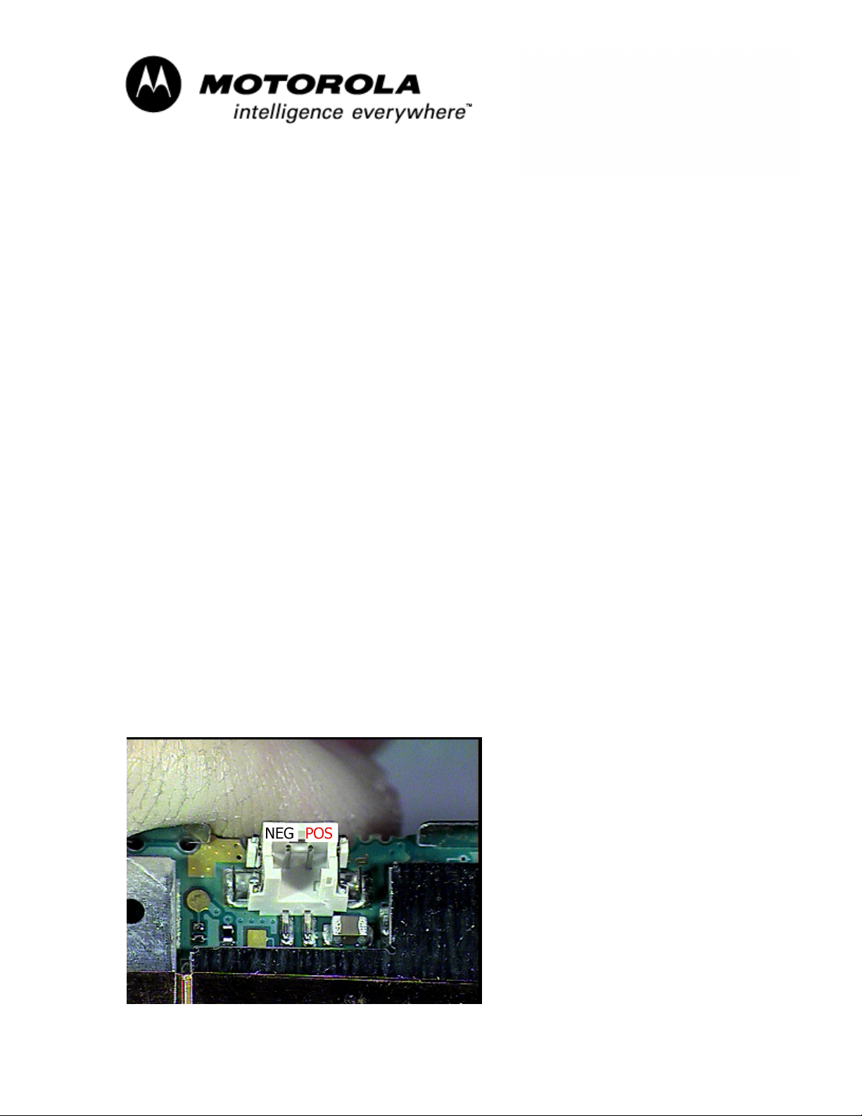
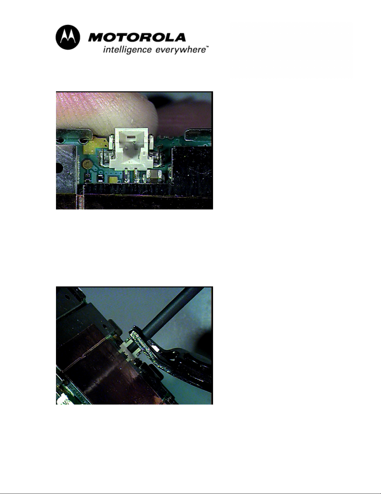
3) Using a flatblade jeweler’s screwdriver, break off the of the PCB battery
connector negative (-) pin by moving the pin back and forth several times
until it breaks at the connector’s base. Refer to Photos 1 thru 4 below.
Photo #1-Original PCB Batt Connector
.
MOTOROLA INTERNAL USE ONLY Page 2
Page 3
`
Consumer Solutions & Support
US Competency Center
600 North US Highway 45
Libertyville, Illinois 60048
Website: gs.mot.com
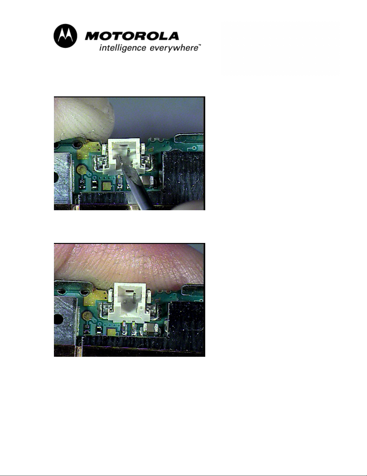
Photo #2-Bending PCB Batt Connector Negative Pin
Photo #3-PCB Batt Connector Negative Pin Broken Off
MOTOROLA INTERNAL USE ONLY Page 3
Page 4
`
Consumer Solutions & Support
US Competency Center
600 North US Highway 45
Libertyville, Illinois 60048
Website: gs.mot.com
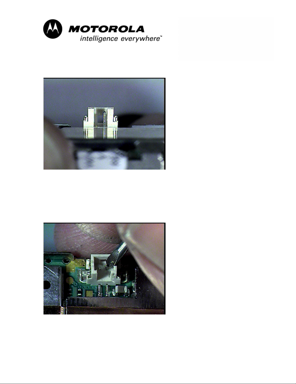
Photo #4-Side View Of PCB Batt Connector Without Negative Pin
4) Using the flatblade jeweler’s screwdriver, bend the PCB Battery Connector
positive (+) pin approximately 20 degrees towards the center of the
connector. This is to allow clearance between the heat shrink tubing
(installed later in this procedure) & the PCB connector body. Refer to
Photos #5 & #6.
Photo #5-Bending Positive Pin
MOTOROLA INTERNAL USE ONLY Page 4
Page 5
`
Consumer Solutions & Support
US Competency Center
600 North US Highway 45
Libertyville, Illinois 60048
Website: gs.mot.com
Photo #6-Positive Pin Bent Toward Center Of Connector
In Steps 5 & 6, the height of the PCB battery connector is being used as a gauge
to cut the heat shrink to the correct length:
5) Insert a 3/32 diameter heat shrink tubing (3M Part # FP-301) until it fully
seats into the PCB battery connector.
6) Using a diagonal wire cutter, cut the heat shrink flush to the top of the
connector. The cut length must not exceed 4mm. Refer to Photo #7
Photo #7-Using PCB Batt Connector To Cut Heat Shrink to Proper Length
7) Remove the heat shrink from the connector.
MOTOROLA INTERNAL USE ONLY Page 5
Page 6
`
Consumer Solutions & Support
US Competency Center
600 North US Highway 45
Libertyville, Illinois 60048
Website: gs.mot.com
NOTE: If a short condition occurs while performing the following steps, cut
any ONE of the battery leads immediately to break the circuit. DO NOT CUT
BOTH BATTERY LEADS SIMULTANEOUSLY. Welding of the leads can
occur and the battery leads will quickly become extremely hot due to the
high current condition, possibly resulting in a burn.
8) Using the diagonal wire cutter, cut the side of the battery connector
housing which is closest to the red lead in order to remove the lead from
the battery connector. Use caution to avoid damaging the battery wire or
contact pin. Refer to Photo #8.
Photo #8-Cutting Batt Connector Housing
9) Remove the red lead from the battery connector housing. DO NOT
REMOVE THE BLACK LEAD AT THIS TIME.
10) Install the heat shrink tubing that was cut in the previous steps over the
red battery lead.
11) Apply a drop of liquid flux to the battery red lead contact pin.
12) Add solder to the soldering iron tip. Avoid using excess solder.
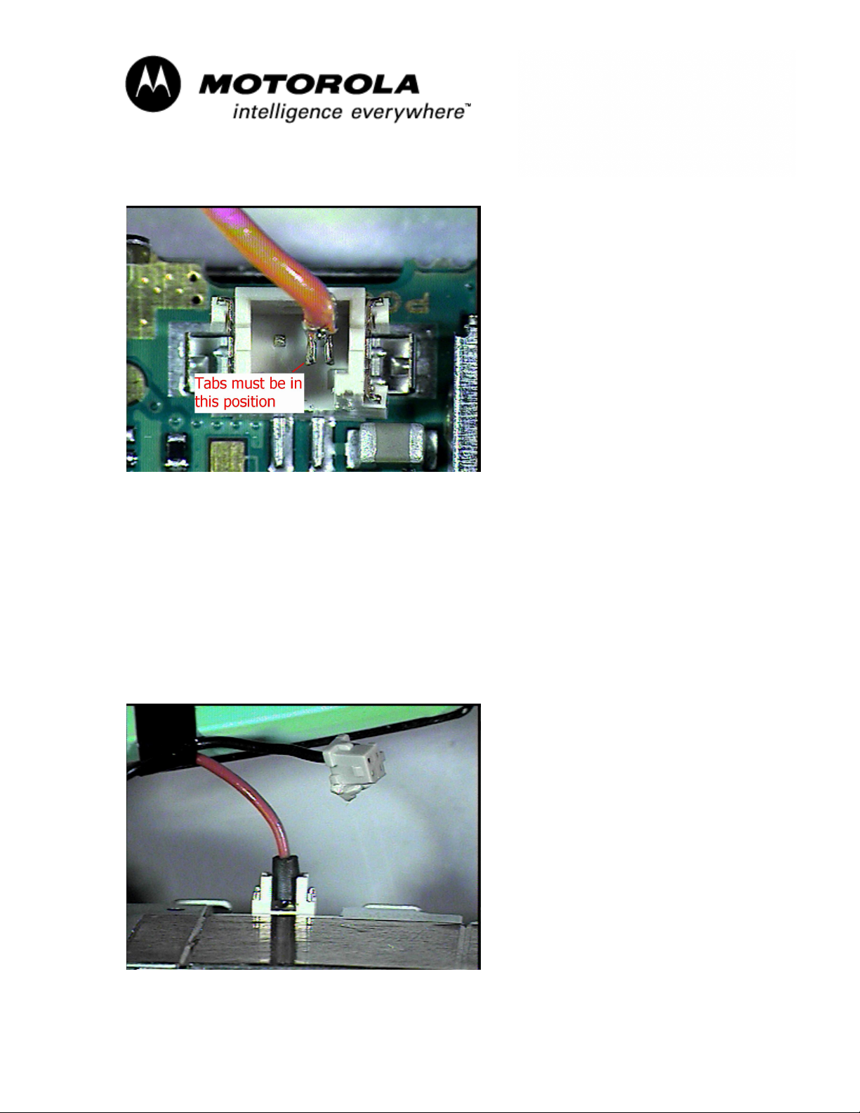
13) Position the the red battery lead pin so it’s tabs are facing toward the
opening of the PCB batt connector. The tabs must not face the neg
side of the batt connector. Refer to Photo #9.
MOTOROLA INTERNAL USE ONLY Page 6
Page 7
`
Consumer Solutions & Support
US Competency Center
600 North US Highway 45
Libertyville, Illinois 60048
Website: gs.mot.com
Photo #9-Batt (+) Lead Tab Position
14) Attach the battery lead pin to the PCB battery connector positive pin and
touch the soldering iron tip to the connection. Use care to avoid excessive
heat.
15) Verify proper soldering adhesion has taken place by gently pulling on the
red lead. If the lead disengages from the PCB connector pin, repeat Steps
11 thru 14.
16) Slip the heat shrink tubing over the soldered connection until it fully seats
into the PCB battery connector.
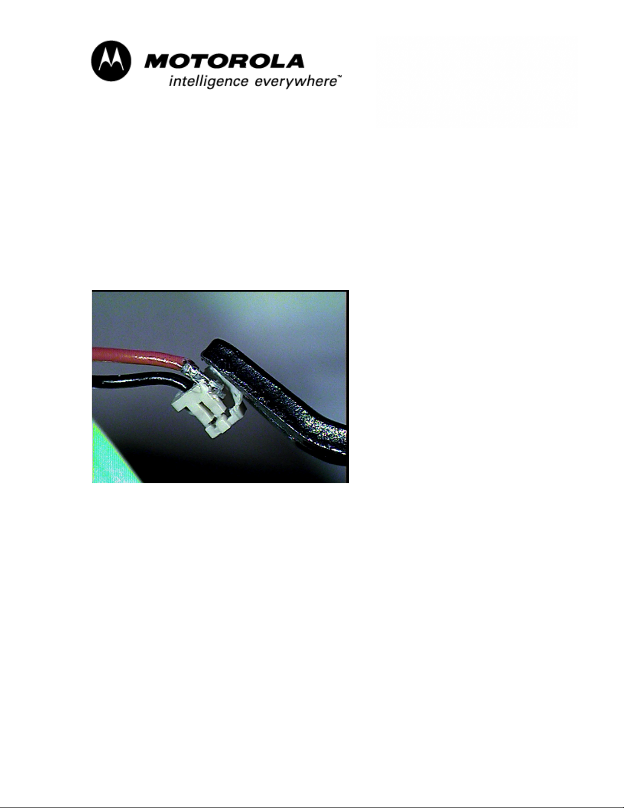
17) Using a heat gun, apply heat to the tubing. Refer to Photo #10.
Photo #10-Positive Lead Complete
18) Repeat Steps 8 & 9 with the black battery lead.
MOTOROLA INTERNAL USE ONLY Page 7
Page 8

`
Consumer Solutions & Support
US Competency Center
600 North US Highway 45
Libertyville, Illinois 60048
Website: gs.mot.com
19) Squeeze the black battery lead pin tabs together using needle nose
pliers. Refer to Photo #11,
Photo #11-Black Battery Lead Pin Tabs
20) Tin the lead’s contact pin with solder. Avoid excessive heat.
21) Add a drop of flux to the pin.
22) Insert the pin into the PCB battery connector’s metal ground tab which is
located on the side of the connector near C840. Ensure the pin is seated
fully into the metal tab. Refer to Photo #12
Photo #12-Battery Black Lead to PCB Connection
23) Solder the black battery lead pin to the connector’s ground tab as shown
in Photo #12 above.
MOTOROLA INTERNAL USE ONLY Page 8
Page 9

`
Consumer Solutions & Support
US Competency Center
600 North US Highway 45
Libertyville, Illinois 60048
Website: gs.mot.com
24) Dress the battery leads so they do not exceed the battery height. Refer
to Photo #13.
Photo #13-Dressing Battery Leads
25) Reassemble the unit.
26) Verify battery charger is functional and unit is able to power on.
Service Inventory:
1) For US Band products only-Re-flex all units with flex version 171
2) For Euro Band products only-Re-flex all units with flex version 173
Service Entry Codes
Please ensure that repairs of this type are logged on to the applicable database
as follows:
ServiceLink-
Customer Complaint: BAT02 Battery Life Short
Problem Found: BAT05 Battery Meter Inaccurate
Reference Designator: J Connector
Repair: RBT10 Replace Battery-Mech Fault Contacts
PRC E-service Entry Codes
Complaint Code: 4002 Short Battery Life
4005 Battery Meter Inaccurate
Root Cause Code: 1006 Mechanical Parts Oxidation
MOTOROLA INTERNAL USE ONLY Page 9
 Loading...