

Page 1
Level 3 Service Manual
Product Family B65
Tri-Band Digital Wireless Telephone
T720
GSM 850/1900 MHz & GPRS Technologies
Page 2

Page 3

1 and 2
Table of Contents
Level 3 Service Manual Table of Contents
B65
6881040B60
Contents
Introduction . . . . . . . . . . . . . . . . . . . . . . . . . . . . . . . . . . . . . . . . . . . . . . . . . . . . . . . . . . . . . . . . . . . . . . . . . . . . . . 5
Product Identification . . . . . . . . . . . . . . . . . . . . . . . . . . . . . . . . . . . . . . . . . . . . . . . . . . . . . . . . . . . . . . . . 5
Product Names . . . . . . . . . . . . . . . . . . . . . . . . . . . . . . . . . . . . . . . . . . . . . . . . . . . . . . . . . . . . . . . . . . . . . 5
Product Changes . . . . . . . . . . . . . . . . . . . . . . . . . . . . . . . . . . . . . . . . . . . . . . . . . . . . . . . . . . . . . . . . . . . . 5
Regulatory Agency Compliance . . . . . . . . . . . . . . . . . . . . . . . . . . . . . . . . . . . . . . . . . . . . . . . . . . . . . . . . 5
Computer Program Copyrights . . . . . . . . . . . . . . . . . . . . . . . . . . . . . . . . . . . . . . . . . . . . . . . . . . . . . . . . 6
About this Service Manual . . . . . . . . . . . . . . . . . . . . . . . . . . . . . . . . . . . . . . . . . . . . . . . . . . . . . . . . . . . . 6
Warranty Service Policy . . . . . . . . . . . . . . . . . . . . . . . . . . . . . . . . . . . . . . . . . . . . . . . . . . . . . . . . . . . . . . 7
Parts Replacement . . . . . . . . . . . . . . . . . . . . . . . . . . . . . . . . . . . . . . . . . . . . . . . . . . . . . . . . . . . . . . . . . . 8
Specifications . . . . . . . . . . . . . . . . . . . . . . . . . . . . . . . . . . . . . . . . . . . . . . . . . . . . . . . . . . . . . . . . . . . . . . . . . . . 9
Product Overview . . . . . . . . . . . . . . . . . . . . . . . . . . . . . . . . . . . . . . . . . . . . . . . . . . . . . . . . . . . . . . . . . . . . . . . . 11
Features . . . . . . . . . . . . . . . . . . . . . . . . . . . . . . . . . . . . . . . . . . . . . . . . . . . . . . . . . . . . . . . . . . . . . . . . . . 11
General Operation . . . . . . . . . . . . . . . . . . . . . . . . . . . . . . . . . . . . . . . . . . . . . . . . . . . . . . . . . . . . . . . . . . . . . . . . 15
Controls, Indicators, and Input/Output (I/O) Connections . . . . . . . . . . . . . . . . . . . . . . . . . . . . . . . . . . 15
User Interface Menu Structure . . . . . . . . . . . . . . . . . . . . . . . . . . . . . . . . . . . . . . . . . . . . . . . . . . . . . . . 18
Alert Settings . . . . . . . . . . . . . . . . . . . . . . . . . . . . . . . . . . . . . . . . . . . . . . . . . . . . . . . . . . . . . . . . . . . . . 18
Battery Function . . . . . . . . . . . . . . . . . . . . . . . . . . . . . . . . . . . . . . . . . . . . . . . . . . . . . . . . . . . . . . . . . . . 19
Operation . . . . . . . . . . . . . . . . . . . . . . . . . . . . . . . . . . . . . . . . . . . . . . . . . . . . . . . . . . . . . . . . . . . . . . . . . 19
Tools and Test Equipment . . . . . . . . . . . . . . . . . . . . . . . . . . . . . . . . . . . . . . . . . . . . . . . . . . . . . . . . . . . . . . . . . 21
Disassembly . . . . . . . . . . . . . . . . . . . . . . . . . . . . . . . . . . . . . . . . . . . . . . . . . . . . . . . . . . . . . . . . . . . . . . . . . . . . . 22
Removing and Replacing the Battery Housing and Battery . . . . . . . . . . . . . . . . . . . . . . . . . . . . . . . . 22
Removing and Replacing the Subscriber Identity Module (SIM) . . . . . . . . . . . . . . . . . . . . . . . . . . . . . 24
Removing and Replacing the Antenna . . . . . . . . . . . . . . . . . . . . . . . . . . . . . . . . . . . . . . . . . . . . . . . . . 25
Removing and Replacing the Rear Housing Assembly . . . . . . . . . . . . . . . . . . . . . . . . . . . . . . . . . . . 25
Removing and Replacing the Transceiver Board Assembly . . . . . . . . . . . . . . . . . . . . . . . . . . . . . . . . 28
Removing and Replacing the Keypad . . . . . . . . . . . . . . . . . . . . . . . . . . . . . . . . . . . . . . . . . . . . . . . . . . 30
Removing and Replacing the Flip Cover . . . . . . . . . . . . . . . . . . . . . . . . . . . . . . . . . . . . . . . . . . . . . . . . 31
Removing the LED Light Guard . . . . . . . . . . . . . . . . . . . . . . . . . . . . . . . . . . . . . . . . . . . . . . . . . . . . . . 32
Removing and Replacing the Flip Assembly . . . . . . . . . . . . . . . . . . . . . . . . . . . . . . . . . . . . . . . . . . . . . 33
Removing and Replacing the Display Module . . . . . . . . . . . . . . . . . . . . . . . . . . . . . . . . . . . . . . . . . . . . 36
Subscriber Identity Module (SIM) and Identification . . . . . . . . . . . . . . . . . . . . . . . . . . . . . . . . . . . . . . . . . . . . 37
SIM Card . . . . . . . . . . . . . . . . . . . . . . . . . . . . . . . . . . . . . . . . . . . . . . . . . . . . . . . . . . . . . . . . . . . . . . . . . 37
Personality Transfer . . . . . . . . . . . . . . . . . . . . . . . . . . . . . . . . . . . . . . . . . . . . . . . . . . . . . . . . . . . . . . . . 37
Identification . . . . . . . . . . . . . . . . . . . . . . . . . . . . . . . . . . . . . . . . . . . . . . . . . . . . . . . . . . . . . . . . . . . . . . 37
Troubleshooting . . . . . . . . . . . . . . . . . . . . . . . . . . . . . . . . . . . . . . . . . . . . . . . . . . . . . . . . . . . . . . . . . . . . . . . . . 39
Manual Test Mode . . . . . . . . . . . . . . . . . . . . . . . . . . . . . . . . . . . . . . . . . . . . . . . . . . . . . . . . . . . . . . . . . 39
Manual Test Mode Commands . . . . . . . . . . . . . . . . . . . . . . . . . . . . . . . . . . . . . . . . . . . . . . . . . . . . . . . . 39
Troubleshooting Chart . . . . . . . . . . . . . . . . . . . . . . . . . . . . . . . . . . . . . . . . . . . . . . . . . . . . . . . . . . . . . . 41
Programming: Software Upgrade and Flexing . . . . . . . . . . . . . . . . . . . . . . . . . . . . . . . . . . . . . . . . . . . 43
Part Number Charts . . . . . . . . . . . . . . . . . . . . . . . . . . . . . . . . . . . . . . . . . . . . . . . . . . . . . . . . . . . . . . . . . . . . . . . 45
Related Publications . . . . . . . . . . . . . . . . . . . . . . . . . . . . . . . . . . . . . . . . . . . . . . . . . . . . . . . . . . . . . . . . 45
Exploded View Diagram . . . . . . . . . . . . . . . . . . . . . . . . . . . . . . . . . . . . . . . . . . . . . . . . . . . . . . . . . . . . . 46
Exploded View Parts List . . . . . . . . . . . . . . . . . . . . . . . . . . . . . . . . . . . . . . . . . . . . . . . . . . . . . . . . . . . 47
Accessories . . . . . . . . . . . . . . . . . . . . . . . . . . . . . . . . . . . . . . . . . . . . . . . . . . . . . . . . . . . . . . . . . . . . . . . . 48
6881040B60 August 01, 2002 3
Page 4

Table of Contents Product Family B65
4 August 01, 2002 6881040B60
Page 5

1 and 2
B65
Level 3 Service Manual Introduction
6881040B60
Introduction
Motorola® Inc. maintains a worldwide organization that is dedicated to provide
responsive, full-service customer support. Motorola products are serviced by an
international network of company-operated product care centers as well as
authorized independent service firms.
Available on a contract basis, Motorola Inc. offers comprehensive maintenance and
installation programs that enable customers to meet requirements for reliable,
continuous communications.
To learn more about the wide range of Motorola service programs, contact your local
Motorola products representative or the nearest Customer Service Manager.
Product Identification
Motorola products are identified by the model number on the housing. Use the entire
model number when inquiring about the product. Numbers are also assigned to
chassis and kits. Use these numbers when requesting information or ordering
replacement parts.
Product Names
Product names included in Product Family 0B65 (PF B65) telephones are listed on
the front cover. Product names are subject to change without notice. Some product
names, as well as some frequency bands, are available only in certain markets.
Product Changes
When electrical, mechanical or production changes are incorporated into Motorola
products, a revision letter is assigned to the chassis or kit affected, for example;
-A, -B, or -C.
The chassis or kit number, complete with revision number is imprinted during
production. The revision letter is an integral part of the chassis or kit number and
is also listed on schematic diagrams and printed circuit board layouts.
Regulatory Agency Compliance
This device complies with Part 15 of the FCC Rules. Operation is subject to the
following conditions:
• This device may not cause any harmful interference, and
• must accept interference received, including interference that may cause
undesired operation.
This class B device also complies with all requirements of the Canadian
Interference-Causing Equipment Regulations (ICES-003).
Cet appareil numérique de la classe B respecte toutes les exigences du Règlement
sur le matériel brouilleur du Canada.
6881040B60 August 01, 2002 5
Page 6

6881040B60
B65
Introduction Product Family B65
1 and 2
Computer Program Copyrights
The Motorola products described in this manual may include Motorola computer
programs stored in semiconductor memories or other media that are copyrighted
with all rights reserved worldwide to Motorola. Laws in the United States and other
countries preserve for Motorola, Inc. certain exclusive rights to the copyrighted
computer programs, including the exclusive right to copy, reproduce, modify,
decompile, disassemble, and reverse-engineer the Motorola computer programs in
any manner or form without Motorola's prior written consent. Furthermore, the
purchase of Motorola products shall not be deemed to grant either directly or by
implication, estoppel, or otherwise, any license or rights under the copyrights,
patents, or patent applications of Motorola, except for a nonexclusive license to use
the Motorola product and the Motorola computer programs with the Motorola
product.
About this Service Manual
Using this service manual and the suggestions contained in it assures proper
installation, operation, and maintenance of PF B65 telephones. Refer questions
about this manual to the nearest Customer Service Manager.
A product family is the group of products having the same account product code
(APC). To locate the APC on a device, refer to “Mechanical Serial Number (MSN)”
later in this manual.
Audience
This manual aids service personnel in testing and repairing PF B65 telephones.
Service personnel should be familiar with electronic assembly, testing, and troubleshooting methods, and with the operation and use of associated test equipment.
Use of this manual assures proper installation, operation, and maintenance of
Motorola products and equipment. It contains all service information required for
the equipment described and is current as of the printing date.
Scope
The scope of this document is to provide the basic information relating to PF B65
telephones, and also to provide procedures and processes for repairing the units at
Level 1 and 2 service centers including:
•Unit swap out
• Repairing of mechanical faults
• Basic modular troubleshooting
• Testing and verification of unit functionality
• Initiate warranty claims and send faulty modules to Level 3 or 4 repair
centers
PRELIMINARY
6 August 01, 2002 6881040B60
Page 7

Level 3 Service Manual Introduction
Conventions
Special characters and typefaces, listed and described below, are used in this
manual to emphasize certain types of information.
➧
G
E
E
Note: Emphasizes additional information pertinent to the subject
matter.
Caution: Emphasizes information about actions that may result in
equipment damage.
Warning: Emphasizes information about actions that may result in
personal injury.
Keys to be pressed are represented graphically. For example, instead of “Press
the Enter Key”, you will see “Press
Information from a screen is shown in text as similar as possible to what
appears in the display. For example, ALERTS or ALERTS or ALERTS.
Information that you need to type is printed in boldface type
E”.
Revisions
Any changes that occur after manuals are printed are described in publication
revision bulletins (PMRs). These bulletins provide change information that can
include new parts listing data, schematic diagrams, and printed circuit board
layouts.
Warranty Service Policy
The product is sold with the standard 12-month warranty terms and conditions.
Accidental damage, misuse, and extended warranties offered by retailers are not
supported under warranty. Non warranty repairs are available at agreed fixed
repair prices.
Out of Box Failure Policy
The standard out of box failure criteria applies. Customer units that fail very early
on after the date of sale, are to be returned to Manufacturing for root cause analysis,
to guard against epidemic criteria. Manufacturing will bear the costs of early life
failure.
Product Support
Customer’s original unit will be repaired but not refurbished as standard.
Appointed Motorola Service Hubs will perform warranty and non-warranty field
service for level 2 (assemblies) and level 3 (limited PCB component). The Motorola
HTC centers will perform level 4 (full component) repairs.
6881040B60 August 01, 2002 7
Page 8

Introduction Product Family B65
Customer Support
Customer support is available through dedicated Call Centers and in-country help
desks. Product Service training should be arranged through the local Motorola
Support Center.
Parts Replacement
When ordering replacement parts or equipment, include the Motorola part number
and description used in the service manual or supplement.
When ordering crystals or channel elements, specify the Motorola part number,
description, crystal frequency, and operating frequency desired.
When the Motorola part number of a component is not known, use the product model
number or other related major assembly along with a description of the related
major assembly and of the component in question.
In the U.S.A., to contact Motorola, Inc. on your TTY, call: 800-793-7834.
Accessories and Aftermarket Division (AAD)
Replacement parts, test equipment, and manuals can be ordered from AAD.
U.S.A. Outside U.S.A.
Phone: 800-422-4210 Phone: 847-538-8023
FAX: 800-622-6210 FAX: 847-576-3023
For spare parts in the EMEA region call +44 131 479 1274.
For spare parts in the Asia region call +65 648 62995.
PRELIMINARY
8 August 01, 2002 6881040B60
Page 9

Level 3 Service Manual Specifications
Specifications
General Function Specification
Frequency Range GSM 880-915 MHz Tx (with EGSM)
Frequency Range DCS 1710-1785 MHz Tx
Channel Spacing 200 kHz
Channels 174 EGSM, 374 DCS carriers with 8 channels per carrier
Modulation GMSK at BT = 0.3
Transmitter Phase Accuracy 5 Degrees RMS, 20 Degrees peak
Duplex Spacing 45 MHz GSM, 95 MHz DCS
Frequency Stability ± 0.10 ppm of the downlink frequency (Rx)
Operating Voltage +3.0V dc to +4.2V dc (battery)
Average Transmit Current 310 mA nominal at room temperature
Average Stand-by Current 6.4 mA (DRX2), 3.5 mA (DXR9) nominal at room temperature
Dimensions, with 550 mAh battery 90.47 mm x 47.3 mm x 23.3 mm (with CLI included)
Size (Volume) 80.67 cc with 550 mAh battery
Weight 106 gm with 550 mAh battery
Temperature Range -10° C to +55° C (+15° F to +130° F)
Battery Life, 550 mAh LI Ion Battery Talk Time up to 220 minutes
925-960 MHz Rx
1805-1880 MHz Rx
+4.4V dc to +6.3V dc (external connector)
90.47 mm x 47.3 mm x 21.3 mm (without CLI)
86.19 cc with 750 mAh battery
93.04 cc with 1100 mAh battery
111 gm with 750 mAh battery
122 gm with 1100 mAh battery
Standby up to 152 hours
All talk and standby times are approximate and depend on
network configuration, signal strength, and features selected.
Standby times are quoted as a range from DRX=2 to DRX=9.
Talk times are quoted as a range from DTX off to DTX on.
Transmitter Function Specification
RF Power Output 33 dBm nominal GSM, 30 dBm nominal DCS
Output Impedance 50 ohms nominal
Spurious Emissions -36 dBm from 0.1 to 1 GHz, -30 dBm from 1 to 4 GHz
Receiver Function Specification
Receive Sensitivity -106 dBm GSM, -104 dBm DCS
RX bit error rate (100k bits) Type II < 2%
Channel Hop Time 500 microseconds
Time to Camp Approximately 5-10 seconds
Speech Coding Function Specification
Speech Coding Types FR - Regular pulse excitation / linear predictive coding with long
term prediction (RPE LPC with LTP)
HR - Vector sum excited linear prediction (VSELP)
EFR - Algebraic CELP (ACELP)
AMR - Algebraic CELP (ACELP)
6881040B60 August 01, 2002 9
Page 10

Specifications Product Family B65
Speech Coding Function Specification
Bit Rate 13.0 kbps (FR)
Frame Duration 20 ms
Block Length 260 bits
Classes Class 1 bits = 182 bits; Class 2 bits = 78 bits
Bit Rate with FEC Encoding 22.8 kbps
12.2 kbps (EFR)
4.75 - 12.2 kbps (8 AMR TCH/FS modes)
5.6 kbps (HR)
4.75 - 7.95 kbps (6 AMR TCH/HS modes)
PRELIMINARY
10 August 01, 2002 6881040B60
Page 11

Level 3 Service Manual Product Overview
Product Overview
Motorola PF B65 telephones feature global system for mobile communications
(GSM) air interface, general packet radio service (GPRS) transport technology, and
wireless application protocol (WAP) Internet. The PF B65 incorporates a color user
interface (UI) that is both icon and list-based for easy operation, allows Short
Message Service (SMS) text messaging, and includes personal information manager
(PIM) functionality. The PF B65 is a dual-band phone that allows roaming within
the GSM 900 MHz and digital cellular system (DCS)1800 MHz bands.
PF B65 telephones support GPRS and SMS in addition to traditional circuit
switched transport technologies. GPRS, where available, provides substantial
increases in mobile data communications performance and the efficient use of radio
spectrum. Data transmission rates for GSM networks can potentially increase from
the current rate of 9.6 kbps up to a theoretical maximum of 171.2 kbps. An increased
data rate is by no means the only benefit provided by GPRS. A key advantage is
the provision of a permanent virtual connection to the network. This “always on”
connection is possible because GPRS uses packet data transfer so that, for example,
email can be downloaded in “background mode.” There is no need for the user to
reconnect before requesting a service, eliminating connection set-up delays and
adding convenience and immediacy to data services access. The “virtual” nature of
this connection means that network resources are not consumed during periods
when a user is not actually sending or receiving data.
Features
The telephones are made of polycarbonate plastic with a metal enclosure. The
display and speaker, as well as the keypad, transceiver printed-circuit board (PCB),
microphone, charger and headphone connectors, and power button are contained
within the clam form-factor housing. The standard 550 mAh Lithium Ion (Li Ion)
battery fits behind the back cover.
The phone accepts 3V mini subscriber identity module (SIM) cards which fit into
the SIM holder underneath the battery. The antenna is a fixed stub type antenna.
Inexpensive direct connection to a computer or handheld device via RS232 or USB
for data and fax calls, and for synchronizing phonebook entries with TrueSync®
software, can be accomplished by using the optional data cable and soft modem.
PF B65 telephones use advanced, self-contained, sealed, custom integrated circuits
to perform the complex functions required for GSM GPRS communication. Aside
from the space and weight advantage, microcircuits enhance reliability, simplify
maintenance, and provide a wide variety of operational functions.
Features available in this family of telephones include:
• Low voltage technology that provides increased standby and talk times
• Extended GSM (EGSM) channels
• Tri-coder/decoder (CODEC) that allows full rate, half rate, and enhanced full
rate modes of transmission
• Supports mobile originated/mobile terminated SMS, concatenated SMS, and
cell broadcast messages
• Supports GPRS, circuit switched, and SMS networks
• WAP 1.1 compliant
1
1
1
1. Network, subscription and SIM card or service provider dependent feature. Not available in all areas.
6881040B60 August 01, 2002 11
Page 12

Product Overview Product Family B65
• Supports SIM Toolkit (STK), Class 2
• Caller ID with link to phone book alerts
• Dual tinted mirror film (TMF) displays with electroluminescent (EL)
backlighting: internal 96 x 64 pixel; external 96 x 16 pixel.
• Internal display provides 3 lines of text, 1 line of icons, and 1 line of prompts.
• Display zoom
• Display animation
• PIM functionality includes: date book, message center, and 400 number phone
book with Starfish® and TrueSync® support
• Voice activation for phonebook entries and menu shortcuts
• Voice note voice recorder
• iTAP™ software for predictive text entry
• Turbo Dial® abbreviated dialing.
• Multi-language support
•32 alerts
• VibraCall® vibrating alert
• Data capable without PC card using RS232 or USB
• Integrated headset jack
• Smart button operation
• Hearing aid telephone interconnection system (HATIS) support
2
1
1
1
3
Speaker Dependant Voice Activation and Voice Note Recording
This feature allows voice tags to be used for voice dialing up to 20 phone numbers
in the phone book and for creating up to 5 voice shortcuts for menu items. The phone
must be “trained” by the voice tag being read into the phone’s memory twice before
it is recognized.
Voice tags can be added to the phone’s memory using the usual name addition
methods (i.e., via the phone book menu structure or with the shortcut editor).
➧
➧
1. Designed to synchronize with basic features of the initial release of many popular Personal Information Management (PIM) software and hardware
products.
2. Use of this function may be subject to varying State and Federal laws regarding privacy of phone conversations.
3. Not compatible with all hearing aids. Hearing aids must contain a T-coil. T-coil must be activated when using the phone.
12 August 01, 2002 6881040B60
PRELIMINARY
The user cannot place or receive calls while adding voice tags to the phone’s memory.
Because the GSM standard does not provide the option to store voice tags onto the
SIM card, voice tags are added to the phone’s memory.
Page 13

Level 3 Service Manual Product Overview
PF B65 telephones also include a voice note recorder that allows up to 2 minutes of
personal messages to be recorded. This feature has a complete set of record,
playback, and management tools that make it easy to store and maintain a list of
personal memos.
Wireless Access Protocol (WAP) 1.1 Compliancy
In the WAP environment, access to the Internet is initiated in wireless markup
language (WML), which is derived from hypertext markup language (HTML). The
request is passed to a WAP gateway which retrieves the information from the server
in standard HTML (subsequently filtered to WML) or directly in WML if available.
The information is then passed to the mobile subscriber via the mobile network.
The PF B65’s microbrowser can be configured for baud, idle timeout, line type,
phone number, and connection type.
➧
➧
Bitmap image data will download as text. If the image is larger than the screen,
only part of the image will display.
When the user receives a call while in browser mode, the browser will pause and
allow the user to resume after completing the call.
SIM Application ToolkitTM - Class 2
SIM Application Toolkit is a value-added service delivery mechanism that allows
GSM operators to customize the services they offer their customers, from the
occasional user who requests sports news and traffic alerts, to a high call time
business user who receives stock alerts and checks flight times. Operators can now
create their own value-added services menu quickly and easily in the phone. The
customized menu will appear as the first menu and may be updated over-the-air
with new services when customers request them.
Simplified Text Entry
Using iTAP™ predictive text entry, pressing a key generates a character, and a
dynamic dictionary uses this to build and display a set of word or name options.
The iTAP™ feature may not be available in all languages.
Caller Line Identification
Upon receipt of a call, the calling party’s phone number is compared to the phone
book. If the number matches a phone book entry, that name displays. If there is no
phone book entry, the incoming phone number displays. If no caller identification
information is available, the Incoming Call message displays.
User must subscribe to a caller line identification service through their service
➧
provider.
6881040B60 August 01, 2002 13
Page 14

Product Overview Product Family B65
Other Features
Detailed descriptions of these and the other PF B65 features can be found in the
appropriate PF B65 telephone user guide listed in the “Related Publications” section
toward the end of this manual.
PRELIMINARY
14 August 01, 2002 6881040B60
Page 15
Level 3 Service Manual General Operation
General Operation
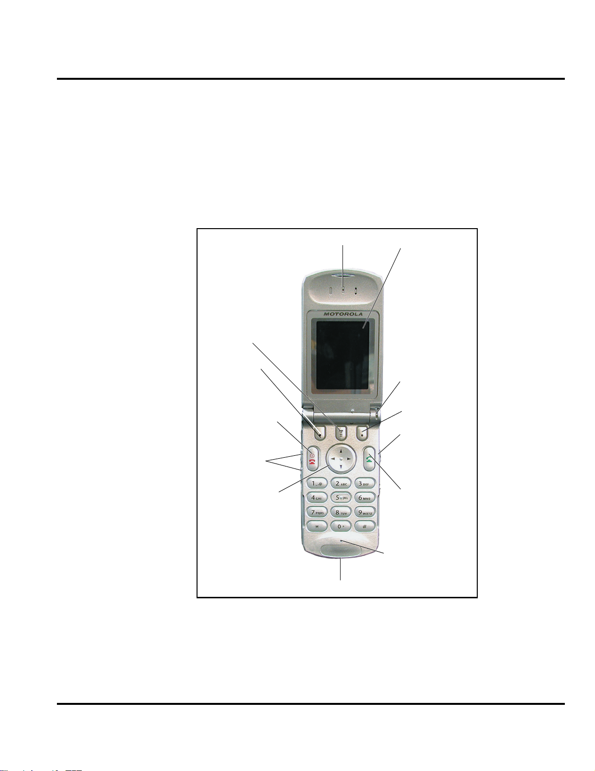
Controls, Indicators, and Input/Output (I/O) Connections
The PF B65 telephone’s controls are located on the sides of the device and on the
keypad (see Figure 1). Indicators, in the form of icons, are displayed on the LCD
(see Figure 2). Service status is indicated by a tri-color light emitting diode (LED)
located at the top of the phone on the right knuckle (Table 1). PF B65 phones have
an audible alert transducer on the top and I/O connectors, consisting of a headset
jack and an accessory port, located on the top and bottom of the phone.
Menu Key
Left Soft Key
Power Key
& End Key
Turn phone on and
off, exit menu system
Volume Keys
4-Way Navigation
Key
Scroll through
menus and lists, set
feature values
Earpiece
Display
Status Light
Right Soft Key
Voice Key
Record voice notes,
phonebook and
shortcut names
Send Key
Make and answer
calls, view recent di-
aled calls list
Microphone
Accessory Connector Port
Figure 1. PF B65 Phone Controls, Indicators and I/O
6881040B60 August 01, 2002 15
Page 16
General Operation Product Family B65
Service Indicator
The service indicator (status light) changes color to show the user the state of the
phone as shown in Table 1, below.
Table 1. Service Indicator States
Indication State
Alternating red / green Incoming call
Flashing green In service, home system
Flashing yellow Roaming, non-home system
Flashing red No service
Liquid Crystal Display (LCD)
The LCD provides a high contrast backlit display for easy readability in all light
conditions. The large bit-mapped 96 x 64 display includes 3 lines of text, 1 line of
icons, and 1 line of prompts.
Display zoom allows setting the phone’s display to show either three lines or two
lines of text plus soft key labels. Three lines of text display more information, while
two lines increase text size for improved visibility.
Display animation makes the phone’s menus move smoothly as the user scrolls up
and down. Turn animation off to conserve the battery.
In Use
Indicator
GPRS
Indicator
Signal
Strength
Indicator
Roam
Indicator
)8?I P VQ5
Service Provider
10:00am
10/10/02
Active
Line
Indicator
^
U
Clock
bg
Messages
r
Web
Access
Phonebook
e
RECENTSTYLES
Menu
Indicator
Soft Key Labels
Te xt
Entry
Mode
Indicator
Battery
Level
Indicator
Ring
Style
Indicator
Message
Waiting
Indicator
Datebook
Figure 2. PF B65 Icon Indicators
Whether a phone displays all indicators depends on the programming and services
➧
PRELIMINARY
16 August 01, 2002 6881040B60
to which the user subscribes.
Page 17

Level 3 Service Manual General Operation
Figure 2 shows common icons displayed on the LCD.
• Signal Strength Indicator. Shows the strength of the phone’s connection
with the network. Calls cannot be sent or received when the “no signal”
indicator is displayed.
• GPRS Indicator. Your service provider may use this indicator to indicate that
a GPRS packet data connection is active. This type of connection may be used
by your service provider to allow faster data transfer speeds. The GPRS
indicator does not mean you are in a call; it indicates only that you are
registered on the network via a GPRS connection.
• In Use Indicator. Appears when a call is in progress.
• Roam Indicator.
5
Appears when the phone uses another network system
outside the user’s home network. When leaving the home network area, the
phone roams, or seeks another network.
• Message Waiting Indicator.
5
Appears when the phone receives a text
message. This is a network-dependent feature.
• Voice Message Waiting Indicator.
1
Appears when a voicemail message is
received. This is a network-dependent feature.
• Battery Level Indicator. Shows the amount of charge left in the battery. The
more segments visible, the greater the charge. Recharge the battery as soon as
possible when the Low Battery warning message appears.
•Active Line. When you use a SIM card that supports dual phone lines, this
indicator shows the current active phone line.
• Ring Style. Shows the current selected alert style. The default setting is a
loud ring.
ï = loud ring
ï = soft ring
ï = vibrate
ï = ring and vibrate
ï = silent
• Menu Indicator. Indicates the user can press the menu soft key to open a
menu.
1. Network, subscription and SIM card or service provider dependent feature. Not available in all areas.
6881040B60 August 01, 2002 17
Page 18

General Operation Product Family B65
User Interface Menu Structure
Figure 3 shows the PF B65 telephone menu structure.
Main Menu
• Recent Calls
• Received Calls
• Dialed Calls
• Notepad
•Call Times
•Call Cost
• Service Dial
• Fixed Dial
• Phonebook
• Picture Viewer
• Datebook
•Quick Dial
•Radio
•Chat
• Messages
•Voicemail
•Text Msgs
• Email Msgs
• Browser Alerts
• Info Services
•Quick Notes
•Outbox
•Drafts
• Ring Styles
•Style
• Style Detail
• My Tones
• Shortcuts
• Voice Notes
• SIM Applications
• Browser
• My Java Apps
• Calculator
• Games
• Settings
Settings Menu
• Call Forward
• Voice Calls
• Fax Calls
• Data Calls
• Cancel All
• Forward Status
• Phone Status
• My Tel. Numbers
• Credit Info/Available
• Active Line
• Battery Meter
• Other Information
• Browser Setup
• In-Call Setup
• In-Call Timer
•Call Cost Setup
•My Caller ID
• Talk and Fax
• Answer Options
• Call Waiting
• Security
• Phone Lock
• Lock Application
• Fixed Dial
•Call Barring
•SIM Pin
•New Passwords
• Java Tools
• Java App Loader
• Java System
• Network Access
• Other Settings
•Personalize
• Main Menu
•Keys
•Greeting
• Wallpaper
• Screen Saver
• Quick Dial
• Initial Setup
• Time and Date
• 1-Touch Dial
• Auto Redial
• Backlight
• Status Light
• Zoom
•Scroll
• Animation
• Language
•Battery Save
• Contrast Setting
•DTMF
•Master Reset
• Master Clear
•Network
•Car Settings
• Headset
Figure 3. PF B65 Menu Structure
Alert Settings
PF B65 telephones include up to 32 preset alert tones and vibrations that can be
applied to all alert events at the same time.
Pressing either volume key mutes the alert.
➧
PRELIMINARY
18 August 01, 2002 6881040B60
Page 19

Level 3 Service Manual General Operation
Battery Function
Battery Gauge
The telephone displays a battery level indicator icon in the idle screen to indicate
the battery charge level. The gauge shows four levels: 100%, 66%, 33%, and Low
Battery.
Battery Removal
Removing the battery causes the device to immediately shut down and any pending
work (for example, partially entered phone book entries or outgoing messages) is
lost.
To ensure proper memory retention, turn OFF the phone before removing the
➧
battery. Immediately replace the old battery with a fresh battery.
Operation
G
If the battery is removed while receiving a message, the message will be lost.
For detailed operating instructions, refer to the appropriate user’s guide listed in
the Related Publications section toward the end of this manual.
6881040B60 August 01, 2002 19
Page 20

General Operation Product Family B65
PRELIMINARY
20 August 01, 2002 6881040B60
Page 21

1 and 2
Level 3 Service Manual Tools and Test Equipment
6881040B60
B65
Tools and Test Equipment
The following table lists tools and test equipment recommended for disassembly
and reassembly of PF B65 telephones. Use either the listed items or equivalents.
Table 2. General Test Equipment and Tools
Motorola Part Number
RSX4043-A Torque Driver Used to remove and replace screws
1
Description Application
—
See Table 7 Rapid Charger
0180386A82
6680388B67
6680388B01 Tweezers, plastic Used during assembly/disassembly
— Digital Multimeter, HP34401A
8102430Z04 GSM / DCS Test SIM Used to enable manual test mode
1. To order in North America, contact Motorola Aftermarket and Accessories Division (AAD) at (800) 422-4210 or
FAX (800) 622-6210; Internationally, AAD can be reached by calling (847) 538-8023 or by fax (847) 576-3023.
2. Not available from Motorola. To order, contact Hewlett Packard at (800) 452-4844.
Torque Driver Bit T-6 Plus, Apex 440-6IP
Torx Plus or equivalent
Antistatic Mat Kit (includes 66-80387A95
antistatic mat, 66-80334B36 ground
cord, and 42-80385A59 wrist band)
Disassembly tool, plastic with flat and
pointed ends (manual opening tool)
2
Used with torque driver
Used to charge battery and power
phone
Provides protection from damage to
device caused by electrostatic discharge
(ESD)
Used during assembly/disassembly of
phone
Used to measure battery voltage
6881040B60 August 01, 2002 21
Page 22

Disassembly Product Family B65
Disassembly
The procedures in this section provide instructions for the disassembly of a PF B65
telephone. Tools and equipment used for the phone are listed in Table 2, preceding.
Many of the integrated devices used in this phone are vulnerable to damage from
G
G
Removing and Replacing the Battery Housing and Battery
E
electrostatic discharge (ESD). Ensure adequate static protection is in place when
handling, shipping, and servicing the internal components of this equipment.
Avoid stressing the plastic in any way to avoid damage to either the plastic or
internal components.
All batteries can cause property damage and/or bodily injury such as burns if a
conductive material such as jewelry, keys, or beaded chains touch exposed terminals.
The conductive material may complete an electrical circuit (short circuit) and
become quite hot. Exercise care in handling any charged battery, particularly when
placing it inside a pocket, purse, or other container with metal objects.
1. Ensure the phone is turned off.
2. Press in and hold the battery housing latch as shown in Figure 4.
BATTERY HOUSING LATCH
Figure 4. Removing the Battery Housing
3. Lift the battery housing completely off the phone.
020200o
22 August 01, 2002 6881040B60
Page 23

Level 3 Service Manual Disassembly
4. Lift the end of the battery and remove it completely (See Figure 5).
BATTERY
E
020201o
Figure 5. Removing the Battery
There is a danger of explosion if the Lithium Ion battery is replaced incorrectly.
Replace only with the same type of battery or equivalent as recommended by the
battery manufacturer. Dispose of used batteries according to the manufacturer’s
instructions.
5. To replace, align the battery with the battery compartment so the contacts on
the battery match the battery contacts in the phone.
6. Insert the battery, printed arrow first, into the battery compartment and push
down.
7. Insert the ridge at the bottom of the battery housing into the base of the phone,
then push the cover down and snap it into place.
6881040B60 August 01, 2002 23
Page 24

Disassembly Product Family B65
Removing and Replacing the Subscriber Identity Module (SIM)
1. Remove the battery housing and battery as described in the procedures.
2. Slide the SIM lock away from the SIM card to unlock as shown in Figure 6.
3. Carefully lift the SIM from its holder.
SIM HOLDER LOCKED
SIM HOLDER UNLOCKED
SIM
020202o
Figure 6. Removing the SIM
4. To replace, insert the SIM into the holder, ensuring the keyed corner of the
SIM aligns with the notch molded into the holder.
5. Lock the SIM into place by sliding the lock towards the SIM card.
6. Replace the battery and battery housing as described in the procedures.
24 August 01, 2002 6881040B60
Page 25

Level 3 Service Manual Disassembly
Removing and Replacing the Antenna
1. Remove the battery housing and battery as described in the procedures.
2. By hand, rotate the antenna counterclockwise until loose. See Figure 7.
ANTENNA
Figure 7. Removing the Antenna
3. When the antenna threads are completely disengaged, pull the antenna
straight out of the phone to remove.
Ensure antenna threads are properly engaged before tightening to prevent damage
G
to the antenna or housing.
4. To replace, insert the threaded end of the antenna carefully into the housing
and, after ensuring the threads are properly engaged, rotate clockwise. Tighten
firmly by hand.
5. Replace the battery and battery housing as described in the procedures.
Removing and Replacing the Rear Housing Assembly
This product contains static-sensitive devices. Use anti-static handling procedures
G
to prevent electrostatic discharge (ESD) and component damage.
1. Remove the battery housing, battery, and antenna as described in the
procedures.
020203o
6881040B60 August 01, 2002 25
Page 26

Disassembly Product Family B65
2. Using a Torx driver with a T-6 bit, remove the 4 screws from the rear housing
assembly (See Figure 8).
SCREWS
SCREWS
020251o
Figure 8. Removing the Rear Housing Assembly Screws
3. Locate the 2 housing catches on the sides of the phone as shown in Figure 9.
4. Using the pointed end of the disassembly tool, depress the housing catches to
release the rear housing assembly from the front housing.
26 August 01, 2002 6881040B60
Page 27

Level 3 Service Manual Disassembly
5. Rotate the rear housing assembly and pull it away from the front housing to
remove.
020204o
Figure 9. Removing the rear housing assembly
6. To replace, carefully align rear housing assembly with the front housing, then
press the rear assembly down until the 2 housing catches engage with the
corresponding openings on the rear housing. Press the housings together until
the catches snap into place.
7. Replace the 4 screws and tighten securely. Do not over tighten.
8. Replace the antenna, battery, and battery housing as described in the
procedures.
6881040B60 August 01, 2002 27
Page 28

Disassembly Product Family B65
Removing and Replacing the Transceiver Board Assembly
This product contains static-sensitive devices. Use anti-static handling procedures
G
G
to prevent electrostatic discharge (ESD) and component damage.
1. Remove the battery housing, battery, antenna, and rear housing assembly as
described in the procedures
The flexible printed cable (FPC) (flex) is easily damaged. Exercise extreme care when
handling.
2. Using the plastic tweezers, remove the metal chassis shield (See Figure 10).
.
PLASTIC TWEEZERS
Figure 10. Removing the Chassis Shield
020252o
28 August 01, 2002 6881040B60
Page 29

Level 3 Service Manual Disassembly
3. Carefully work the flat end of the disassembly tool under the flex connector
and disconnect it from the transceiver board (See Figure 11).
DISSASSEMBLY TOOL
FLEX
020205o
Figure 11. Disconnecting the Flex From the Transceiver Board
4. Using the disassembly tool, lift the transceiver board assembly from the front
housing. To replace, insert the transceiver board assembly into the front
housing with the flex connector on top.
5. Insert the flex connector squarely into its mating connector on the transceiver
board and press firmly until it snaps into place.
6. Replace the metal chassis shield, rear housing assembly, antenna, battery, and
battery housing as described in the procedures.
6881040B60 August 01, 2002 29
Page 30

Disassembly Product Family B65
Removing and Replacing the Keypad
1. Remove the battery housing, battery, antenna, rear housing assembly, and
transceiver board assembly as described in the procedures.
2. Lift the keypad from the front housing as shown in Figure 12.
DISASSEMBLY TOOL
KEYPAD
020207o
Figure 12. Removing the Keypad
3. To replace, insert the keypad into the front housing, ensuring the keys align
properly with the openings in the front housing.
4. Replace the transceiver board, metal chassis shield, rear housing assembly,
antenna, battery, and battery housing as described in the procedures.
30 August 01, 2002 6881040B60
Page 31

Level 3 Service Manual Disassembly
Removing and Replacing the Flip Cover
1. Remove the battery housing, battery, antenna, rear housing assembly,
transceiver board assembly, and keypad as described in the procedures.
2. Using the disassembly tool, lift the bottom end of the flip cover away from the
flip assembly as shown in Figure 13.
DISSASSEMBLY TOOL
020253o
Figure 13. Removing the Flip Cover
3. To replace, align the top corners of the flip cover with the opening of the flip
barrel and push down on all 4 corners of the cover until it snaps into place.
4. Replace the transceiver board, metal chassis shield, rear housing assembly,
antenna, battery, and battery housing as described in the procedures.
6881040B60 August 01, 2002 31
Page 32

Disassembly Product Family B65
Removing the LED Light Guard
1. Using the pointed end of the disassembly tool, push the clear plastic LED light
guard out of the front housing from the inside of the housing (See Figure 14).
020261o
Figure 14. Removing the LED Light Guard
2. To replace, insert the LED light guard into the front housing from the front of
the housing assembly, with the curved side of the guard facing the inside of
the phone.
3. Replace the keypad, transceiver board, metal chassis shield, rear housing
assembly, antenna, battery, and battery housing as described in the procedures.
32 August 01, 2002 6881040B60
Page 33

Level 3 Service Manual Disassembly
Removing and Replacing the Flip Assembly
1. Remove the battery housing, battery, antenna, rear housing assembly, metal
sheath, transceiver board, keypad, and flip cover as described in the
procedures.
The flex is fragile and easily damaged. Be very careful when passing the flex through
G
the front housing opening.
2. Seat the flip in the flip hinge disassembly fixture as shown in Figure 15. Gently
push down on the flip hinge to ensure the flip is seated securely in the fixture,
being careful to not damage the flex connector.
3. Close the flip and push the lever on the fixture down until it can go no further.
4. Open the flip and rotate it counterclockwise until the hinge disconnects from
the barrel, exposing the hinge assembly (See Figure 15).
PUSH DOWN TO LOCK
HINGE ASSEMBLY
Figure 15. Removing the Flip Assembly From the Front Housing
020258o
5. Lift the lever on the fixture and remove the display module and front housing,
being careful to not lose the hinge assembly screw or damage the flex connector.
6881040B60 August 01, 2002 33
Page 34

Disassembly Product Family B65
6. To detach the flex connector, rotate the display module and carefully thread
the flex connector through the opening in the base front housing (See
Figure 16).
020259o
Figure 16. Removing the Flex Connector
7. To replace, thread the flex connector through the front housing opening at an
angle.
34 August 01, 2002 6881040B60
Page 35

Level 3 Service Manual Disassembly
8. Close the barrel of the flip on the side where the flex connector is located,
leaving open the side where the hinge assembly will be inserted into the barrel
(See Figure 17).
HINGE ASSEMBLY
020262o
Figure 17. Replacing the Hinge Assembly
9. Insert the hinge assembly into the barrel. Use the flat end of the disassembly
tool to push the hinge assembly into the barrel until it is flat. Rotate the hinge
of the flip assembly into the front housing until they snap together.
10. Replace the keypad, keyboard assembly, spacer gasket, transceiver board
assembly, rear chassis assembly, antenna, battery, and battery housing as
described in the procedures.
6881040B60 August 01, 2002 35
Page 36

Disassembly Product Family B65
Removing and Replacing the Display Module
1. Using a Torx driver with a T-6 bit, remove the 4 screws from the display module
(See Figure 18).
SCREWS
SCREWS
020263
Figure 18. Removing the Display Module
2. Lift the display module up and slide it out if its housing, being careful to not
damage or stress the flex connector.
3. To replace, thread the flex connector into the housing barrel and seat the
display module back into the flip front housing.
4. Replace the 4 display module screws.
5. Replace the keypad, keyboard assembly, spacer gasket, transceiver board
assembly, rear chassis assembly, antenna, battery, and battery housing as
described in the procedures.
36 August 01, 2002 6881040B60
Page 37

Level 3 Service Manual Subscriber Identity Module (SIM) and Identification
Subscriber Identity Module (SIM) and Identification
SIM Card
A SIM is required to access the existing local GSM network, or remote networks
when traveling (if a roaming agreement has been made with the provider).
The SIM contains:
• All the data necessary to access GSM services.
• The ability to store user information such as phone numbers.
• All information required by the network provider to provide access to the
network.
Personality Transfer
A personality transfer is required when a phone is express exchanged or when the
main board is replaced. Personality transfers reproduce the customer's original
personalized details such as menu and stored memory such as phone books, or even
just program a unit with basic user information such as language selection. PF B65
telephones use TrueSync® synchronization software to effect a personality transfer.
Identification
Each Motorola GSM device is labeled with a variety of identifying numbers. The
following information describes the current identifying labels.
Mechanical Serial Number (MSN)
The Mechanical Serial Number (MSN) is an individual unit identity number and
remains with the unit throughout the life of the unit.
The MSN can be used to log and track a unit on Motorola's Service Center Database.
The MSN is divided into 4 sections as shown in Figure 19.
MSN 10 Digits
3 Digits 1 Digit 2 Digits 4 Digits
APC DC DC SNR
Account Product Code
i.e. StarTAC Phone130
TM
Figure 19. MSN Label Breakdown
Distribution Center
i.e. Easter Inch
Date Code: Year and
Month of Shipment
Unit's individual serial
number
000807a
6881040B60 August 01, 2002 37
Page 38

Subscriber Identity Module (SIM) and Identification Product Family B65
International Mobile Station Equipment Identity (IMEI)
The International Mobile station Equipment Identity (IMEI) number is an
individual number unique to the PCB and is stored within the unit's memory. Figure
20 illustrates the various parts of this number.
IMEI 16 Digits
6 Digits 2 Digits 6 Digits 2 Digits
TAC FAC SNR IU
Type Approval Code Distribution Center
factory code
Individual PCB Serial
Number
Internal Use - spare
digits
000808o
Figure 20. IMEI Label Breakdown
Other label number configurations present are:
• TRANSCEIVER NUMBER: Identifies the product type. Normally the SWF
number. (i.e. V100).
• PACKAGE NUMBER: Identifies the equipment type, mode, and language in
which the product is shipped.
38 August 01, 2002 6881040B60
Page 39

Level 3 Service Manual Troubleshooting
Troubleshooting
Manual Test Mode
Motorola PF B65 telephones are equipped with a manual test mode capability. This
allows service personnel to verify functionality and perform fault isolation by
entering keypad commands.
To enter the manual test command mode, a GSM/DCS test SIM must be used.
1. Turn the phone OFF.
2. Remove the battery as described in the procedures.
3. Remove the customer’s SIM card from the phone as described in the
procedures.
4. Insert the test SIM into the SIM slot.
5. Replace the battery as described in the procedures.
6. Turn the phone ON.
Manual Test Mode Commands
Table 3. Manual Test Commands
Key Sequence Test Function/Name Remarks
<Menu>048263* Enter manual test mode
“End” Key Exit manual test mode
54* Suspend Required for all Test Mode Operations
0*0*0 Select tone 0
0*0*1 Select tone 1
0*0*2 Select tone 2
0*0*3 Select tone 3
0*0*4 Select tone 4
0*0*5 Select tone 5
0*0*6 Select tone 6
0*0*7 Select tone 7
0*0*8 Select tone 8
0*0*9 Select tone 9
0*1*X Disable tone X
3*0*1 Enable vibrator
3*0*0 Disable vibrator
5*0*0 Set audio level 0
5*0*1 Set audio level 1
5*0*2 Set audio level 2
5*0*3 Set audio level 3
5*0*4 Set audio level 4
5*0*5 Set audio level 5
5*0*6 Set audio level 6
5*0*7 Set audio level 7
6881040B60 August 01, 2002 39
Page 40

Troubleshooting Product Family B65
Table 3. Manual Test Commands (Continued)
Key Sequence Test Function/Name Remarks
5*0*8 Set audio level 8
5*0*9 Set audio level 9
5*0*10 Set audio level 10
5*0*11 Set audio level 11
5*0*12 Set audio level 12
5*0*13 Set audio level 13
5*0*14 Set audio level 14
5*0*15 Set audio level 15
6*2*2*0*0 Set Audio Path. Int Mic, IntSpk, RX unmute, TX unmute
6*4*6*0*0 Set Audio Path. Boom Mic, Boom Spk, RX unmute, TX unmute
10*0*3 Set band GSM 900
10*0*4 Set band DCS 1800
10*0*5 Set band PCS 1900
10*0*6 Set dual band GSM 900/1800
10*1*0 Read band 3= GSM 4= DCS 5= PCS 6 =GSM/DCS
18*0 Initialize non-volatile memory (Master Reset)
18*1 Initialize non-volatile memory (Master Clear)
55*2*001 Test Display. All pixels ON
55*2*000 Test Display. All pixels OFF
55*2*002 Test Display. Checkerboard pattern A
55*2*003 Test Display. Checkerboard pattern B
55*2*004 Test Display. Border pixels ON
*#06# IMEI Check No Test Mode Required
Phone Set up -->
Phone Status -->
Other
Information
Flex Version/Technology/S-W Version/Readiness Status No Test Mode Required
40 August 01, 2002 6881040B60
Page 41

Level 3 Service Manual Troubleshooting
Troubleshooting Chart
Table 4. PF B65 Telephone: Level 1 and 2 Troubleshooting Chart
Symptom Probable Cause Verification and Remedy
1. Telephone will not turn on or stay on. a) Battery either discharged or
2. Telephone exhibits poor reception or
erratic operation such as calls frequently
dropping or weak or distorted audio.
3. Display is erratic, or provides partial or
no display.
4. Incoming call alert transducer audio
distorted or volume is too low.
defective.
b) Battery connectors open or
misaligned.
c) Transceiver board assembly
defective.
d) keyboard assembly failure. Replace the keyboard assembly. Temporarily
a) Antenna assembly defective. Check to make sure that the antenna pin is
b) Transceiver board assembly
defective.
a) Transceiver board connections
faulty.
b) Flip assembly defective. Temporarily replace the flip assembly with a known
c) Transceiver board assembly
defective.
Faulty transceiver board assembly. Replace the transceiver board assembly (refer to
Measure battery voltage across a 50 ohm (>1
Watt) load. If the battery voltage is <3.25 Vdc,
recharge the battery using the appropriate battery
charger. If the battery will not recharge, replace the
battery. If battery is not at fault, proceed to b.
Visually inspect the battery connectors on both the
battery and the telephone. Realign and, if
necessary, either replace the battery or refer to a
Level 3 Service Center for the battery connector
replacement. If battery connectors are not at fault,
proceed to c.
Remove the transceiver board assembly.
Substitute a known good assembly and
temporarily reassemble the unit. Depress the
PWR button; if unit turns on and stays on,
disconnect the dc power source and reassemble
the telephone with the new transceiver board
assembly. Verify that the fault has been cleared. If
the fault has not been cleared then proceed to d.
connect a +3.6 Vdc supply to the battery
connectors. Depress the PWR button. If unit turns
on and stays on, disconnect the dc power source
and reassemble with the new keyboard assembly.
properly connected to the transceiver board
assembly. If connected properly, substitute a
known good antenna. If the fault is still present,
proceed to b.
Replace the transceiver board assembly (refer to
1c). Verify that the fault has been cleared and
reassemble the unit with the new transceiver board
assembly.
Remove rear chassis assembly from unit, check
general
condition of flexible printed cable (flex). If the flex is
good, check that the flex connector is fully pressed
down. If not, check connector to transceiver board
connections. If faulty connector, replace the
transceiver board assembly. If connector is not at
fault, proceed to b.
good assembly. If fault has been cleared,
reassemble with the new flip assembly. If fault not
cleared, proceed to c.
Replace the transceiver board assembly (refer to
1c). Verify that the fault has been cleared and
reassemble the unit with the new transceiver board
assembly.
1c). Verify that the fault has been cleared and
reassemble the unit with the new transceiver board
assembly.
6881040B60 August 01, 2002 41
Page 42

Troubleshooting Product Family B65
Table 4. PF B65 Telephone: Level 1 and 2 Troubleshooting Chart (Continued)
Symptom Probable Cause Verification and Remedy
5. Telephone transmit audio is weak.
(usually indicated by called parties
complaining of difficulty in hearing voice).
6. Receive audio from earpiece speaker is
weak or distorted.
7. Telephone will not recognize or accept
SIM.
8. Phone does not sense when flip is
opened or closed (usually indicated by
inability to answer incoming calls by
opening the flip, or inability to make
outgoing calls).
a) Microphone connections to the
transceiver board assembly
defective.
b) Microphone defective. Gain access to microphone. Disconnect and
c) Transceiver board assembly
defective.
a) Connections to or from
transceiver board assembly
defective.
b) Flip assembly defective. Temporarily replace the flip assembly with a known
c) Antenna assembly defective. Check to make sure the antenna is installed
d) Transceiver board assembly
defective.
a) SIM defective. Check the SIM contacts for dirt. Clean if necessary
b) Flip assembly defective. Temporarily replace the flip assembly with a known
c) Transceiver board assembly
defective.
a) Flip assembly defective. Temporarily replace the flip assembly with a known
b) Transceiver board assembly
defective.
Gain access to the microphone as described in the
procedures. Check connections. If connector is
faulty proceed to c; if the connector is not at fault,
proceed to b.
substitute a known good microphone. Place a
call and verify improvement in transmit signal as
heard by called party. If good, reassemble with
new microphone. If microphone is not at fault,
reinstall original microphone and proceed to c.
Replace the transceiver board assembly (refer to
1c). Verify that the fault has been cleared and
reassemble the unit with the new transceiver board
assembly.
Gain access to the transceiver board assembly as
described in the procedures. Check flex and the
flex connector from the flip assembly to the
transceiver board assembly. If flex is at fault,
replace flip assembly. If flex connector is at fault,
proceed to d. If connection is not at fault, proceed
to b.
good assembly. If fault has been cleared,
reassemble with the new flip assembly. If fault not
cleared, proceed to c.
correctly. If the antenna is installed correctly,
substitute a known good antenna assembly. If this
does not clear the fault, reinstall the original
antenna assembly and proceed to d.
Replace the transceiver board assembly (refer to
1c). Verify that the fault has been cleared and
reassemble with the new transceiver board
assembly.
and check if fault has been cleared. If the contacts
are clean, insert a known good SIM into the
telephone. Power up the unit and confirm that the
SIM has been accepted. If the fault no longer
exists, replace the defective SIM. If the SIM is not
at fault, proceed to b.
good assembly. If fault has been cleared,
reassemble with the new flip assembly. If fault not
cleared, proceed to c.
Replace the transceiver board assembly (refer to
1c). Verify that the fault has been cleared and
reassemble the unit with the new transceiver board
assembly.
good assembly. If fault has been cleared,
reassemble with the new flip assembly. If fault not
cleared, proceed to b.
Replace the transceiver board assembly (refer to
1c). Verify that the fault has been cleared and
reassemble the unit with the new transceiver board
assembly.
42 August 01, 2002 6881040B60
Page 43

Level 3 Service Manual Troubleshooting
Table 4. PF B65 Telephone: Level 1 and 2 Troubleshooting Chart (Continued)
Symptom Probable Cause Verification and Remedy
9. Vibrator feature not functioning. Transceiver board assembly
10. Internal Charger not working. Faulty charger circuit on
11. Real Time Clock resetting when
standard battery is removed.
12. No or weak audio when using headset. a) Headset not fully pushed home. Ensure the headset plug is fully seated in the jack
defective.
transceiver board assembly.
Lithium button cell in the display
board may be depleted.
b) Faulty jack socket on transceiver
board assembly.
Replace the transceiver board assembly (refer to
1c). Verify that the fault has been cleared and
reassemble the unit with the new transceiver board
assembly.
Test a selection of batteries in the rear pocket of
the desktop charger. Check LED display for the
charging indications. If these are charging
properly, then the internal charger is at fault.
Replace the transceiver board assembly (refer to
1c). Verify that the fault has been cleared and
reassemble the unit with the new transceiver board
assembly.
Refer service to a Level 3 service center for
replacement.
socket. If fault not cleared, proceed to b.
Replace the transceiver board assembly (refer to
1c). Verify that the fault has been cleared and
reassemble the unit with the new transceiver board
assembly.
Programming: Software Upgrade and Flexing
Contact your local technical support engineer for information about equipment and
procedures for flashing and flexing.Part Number Charts
The following charts are provided as a reference for the parts associated with
PF B65 telephones.
Related Publications
Motorola T720 User Guide, English 6809441A06
6881040B60 August 01, 2002 43
Page 44

Troubleshooting Product Family B65
Exploded View Diagram
1
2
3
4
5
6
7
8
9
10
18
17
21
20
19
11
12
13
16
15
14
Figure 21. Exploded View
44 August 01, 2002 6881040B60
Page 45

Level 3 Service Manual Troubleshooting
Exploded View Parts List
Table 5. Exploded View Parts List
Item
Number
1 1586639K01 Flip Cover with CLI 11 0304387F02 Screws, Base (4)
2 0304387F03 Screws, Transceiver (4) 12 0186584K Battery
3 5585953C Hinge Assembly 13 0186683K01 Battery Door, 550 mAh
4 0186645K01 Flip Main Housing 14 5586652K Chassis Latch
5 6186580K01 Display Lens 15 2686590K Chassis Shield
6 0186669K01 Front Housing 16 7586655K Chassis SIM Box
7 7586600K Keypad 17 5087974K Mic
8 4086609K Popple Dome 18 1486604K Mic Boot
9 8586595K01 Stubby Antenna 19 0186636K01 Flip Display Module Assembly
10 1586592K01 Back Housing, Putty Gray 20 0186670K01
Motorola Part
Number
Description
Item
Number
21 6186635K01 Flip CLI Lens Assembly
Motorola Part
Number
Description
Flip Chassis Medallion
Assembly
There is a danger of explosion if the Lithium Ion battery pack is replaced incorrectly.
Replace only with the same type of battery or equivalent as recommended by the
E
battery manufacturer. Dispose of used batteries according to the manufacturer’s
instructions.
Table 6. Postponable Housing Cover Kits
Color Housing Kit
Astrolite Silver SHN9009 SHN9036 SHN9050 SHN9042
Metallic Blue SHN9016 SHN9037 SHN9051 SHN9043
Iris Blue SHN9014 SHN9069 SHN9052 SHN9044
Silver Mint SHN9015 SHN9038 SHN9053 SHN9045
Desert Pearl SHN9026 SHN9039 SHN9054 SHN9046
Classic Red SHN9027 SHN9040 SHN9055 SHN9047
Dark Indigo Metallic SHN9028 SHN9041 SHN9056 SHN9064
Amethyst Gray SHN9029 SHN9049 SHN9057 SHN9065
Green Metallic SHN9030 SHN9048 SHN9058 SHN9066
Battery Door Kit
550mAh Battery
Battery Door Kit
750mAh Battery
Battery Door Kit
1100mAh Battery
Yellow Gold Metallic SHN9031 SHN9070 SHN9059 SHN9067
Unpainted SHN9071 SHN9060 SHN9068
Housing kits contain items 1, 2, 3, 9, 10, 14, 15, and 16. See Table 5.
Battery Door kits contain battery cover, latch, and spring.
6881040B60 August 01, 2002 45
Page 46

Troubleshooting Product Family B65
Accessories
Table 7. Accessories
Part Description Part Number
Battery, slim, 550 mAh SNN5582
Battery, high performance, 750 mAh SNN5588
Battery, extra capacity, 1100 mAh SNN5595
Mid-Rate travel charger SPN4992
Adapter, travel charger, Euro plug SPN4993
Adapter, travel charger, UK plug SPN4994
Adapter, travel charger, Brazilian plug SPN4741
Adapter, travel charger, Argentinian plug SPN4739
Adapter, travel charger, Korean plug SPN4774
Adapter, travel charger, Hong Kong plug SPN4756
Desktop charger, mallard SPN4997
Desktop charger, mallard refresh SPN5029
Desktop charger, mallard with insert SPN5021
Desktop charger, loon SPN5019
Vehicle power adapter SYN7818
Car kit, easy install SYN8597
Car kit, easy install, puck SYN9169
Car kit, pro install, digital S9609
Car kit, pro install, analog S9610
Speakerphone attachment SPN5028
Headset, FM stereo radio SYN8609
Headset, dual, retractable SYN8284
Headset, single, retractable SYN9050
Headset, send / end button SYN9351
Headset, over the ear SYN8908
Headset, silver AAYN4264
Neckloop, hands-free (compatible with T-coil hearing aids) SYN7875
Speaker, hands-free clip-on SYN8610
Desktop station, hands-free SYN8596
Data kit, USB S8951
Data kit, serial multi-connect S8952
Data kit, serial multi-connect for Palm™ III/V S8953
Data cable, USB SKN6311
Data cable, serial SKN6315
Data cable, serial for Palm™ III SKN6320
Data head, serial SYN0279
Belt clip, black SYN8763
Holster, rotating 1586679K01
46 August 01, 2002 6881040B60
Page 47

Page 48

MOTOROLA, the Stylized M Logo, and all other trademarks indicated as such herein are trademarks of Motorola, Inc.
TrueSync and Starfish are registered trademarks of Starfish, Inc., a wholly owned independent subsidiary of Motorola, Inc.
All other product or service names are the property of their respective owners.
® Reg. U.S. Pat. & Tm. Off.
2002 Motorola, Inc.
All rights reserved.
Personal Communications Sector,
1500 Gateway Blvd.
Boynton Beach, FL 33426-8292
@6881040B60@
6881040B60-O
Page 49

A10
J100
N_GSM_EXC_SW
GSM_EXC_SW
N_DCS_SW
DCS_SW
FL130
FL110
N_DCS_SEL
U110
RX_EN
RVCO
U140
RF_V2
U420
GSM
U430
DCS
GSM_TX
DCS_TX
PA_B+
PA_B+
U400
U100
RX_DCS
PA_B+
RX_GSM
RF_V1
N_GSM_SEL
GSM_TX
DCS_TX
PA_B+
VAPC
FL140
FL120
DCS_SEL
RX_LO
DCS_SEL
U120
N_DCS_SEL
RF_V2
GSM_EXC_EN
DCS_EXC_EN
U300
897-1747MHz
N_GSM_SEL
FL160
SF_OUT
TX_EN
RF_V2
VCO_EN
LO_IN
IF_POSITIVE
IF_NEGATIVE
FEEDBACK
N_GSM_SEL
RF_V2
SWITCHED_V CC
U170
IF_OUT
FL170
400MHz
POWER_CONTR OL
TX_EN
U450
TX_KEY_PAC
POWER_DETE CT_SWITCH
SATURATION_DETECT
RX_EN
U301
HIGH_FREQUE NCY_MODULATION
RF SCHEMATIC PAGE 1/2
RX_TUNE_LINE
TX_TUNE_LINE
Page 50

RF SCHEMATIC PAGE 2/2
RF_V2
U203
RF_V2
RVCO
RX_SERIAL_CLOCK
RX_SERIAL_FRAME_SYNC
RX_ACQUIRE
RX_SERIAL_DATA
U202
RF_V1
5V
5V
PRESCALER_IN
HIGH_FREQUENCY_MODULATION
RX_CHARGE_PUMP
TX_CHARGE_PUMP
RF_V2
SWITCHED_VCC
IF_IN
AOC_DRIVE
POWER_DETECTOR_SWITCH
TX_KEY_PAC
N_DCS_SELECT
N_GSM_SELECT
SATURATION_DETECT
RF_V2
RF_V1
U201
TX_CLOCK
TX_KEY
MAGIC_SPI_CS
MAGIC_SPI_CLK
MAGIC_SPI_DATA
TX_SERIAL_DATA_IN
13MHz_CLOCK_OUT
CLK_SELECT
DM_CS
RF_V1
Q240
MNCP_VCC
5V
VREF
RF_V2
N_EXC_EN
N_TX_EN
Q700
RF_V2
N_DCS_SELECT
TX_ENABLE
RVCO
Q502
RF_V2
U710
DCS_SEL
VCO_EN
N_GSM_SELECT
GSM_EXCITER_ENABLE
Q701
SUPERFILTER_OUT
GSM_EXCITER_ENABLE
DCS_EXCITER_ENABLE
RF_V2
Y250
26MHz
DCS_EXCITER_ENA BLE
U501
B+
N_GSM_EXC_SW
RF_V2
N_DCS_SELECT
GSM_EXCITER_ENABLE
5V
U501
RX_EN
DCS_SEL
RX_EN
U500
U500
U503
N_DCS_SW
DCS_SW
GSM_EXC_SW
RF_V2
U500
5V
U503
Page 51

ROTATOR_DET
AL SCHEMATIC - PAGE 1/2
OE_N
RW_N
SR_CSN
EB0_N
EB1_N
U2003
SR_VCC
M
A
R
S
TP_FLASH_CS
CE0
MORT_FLASH_CS
BRST_CLK
OE_N
EB1_N
ADV_N
RESET_0
ECB_N
QVCC
V1
V3
D3
IVDD
JVDD
V2
V3 HVDD
V3
U2000
Flash
EVDD
V2
V2
DVDD
V3
U1000
PATRIOT
CVDD
V2
BVDD
V3
AV DD
V3
VCCA
V3
RESET
T
S
I
O
S
D
D
R
M
T
T
T
T
TP_MUX_CTL
E
E
D
_
D
_
U
K
P
C
S
C
M
D
T
V2
MOD
CLK_SELECT
STBY
GCAP_13MHz_CLOCK
MAGIC_13MHz
OC3
WAT CHDOG
RESET_0
RESET
USB_VP
IRDA_TX
IRDA_RX
IRDA_EN
USB_TXENB
USB_EOP
GCAP_INT
GCAP_32kHz_IN
DATALOG_N
ROTATOR_DET
ROW_4
ROW_3
ROW_2
ROW_1
ROW_0
ROW_4
PWR_END_KEY
COLUMN_1
ROW_4
ROW_3
COLUMN_1
ROW_3
COLUMN_2
ROW_3
ROW_1
ROW_0
ROW_0
ROW_2
ROW_4
ROW_0
COLUMN_0
ROW_0
ROW_3
COLUMN_0
COLUMN_0
ROW_4
COLUMN_2
ROW_4
COLUMN_2
ROW_0
KEYBOARD CIRCUIT
ROW_2
COLUMN_1
ROW_2
ROW_4
ROW_0
ROW_3
ROW_0
COLUMN_1
COLUMN_2
ROW_1
UCTS
UCTS_CE
UCTS2_SIM_RST1
DATALOG_N
URI
URI_CE
UTXD2
V2
DATA(15:0)
ADDRESS(23:0)
U7004
URXD2_SIM_RX1
UDSR_CE
UDSR
DATALOG_N
URTS2_SIM_CLK1
BFDBK_A
RW_N
EIM_CS5
DISP_CS0
EIM_CS2
BRST_CLK
ADV_N
ECB_N
EB0_N
EB1_N
OE_N
UTXD_VDOUT
CE4
CE1
CE0
COLUMN_3
COLUMN_2
A0
SPI_CS7
SPI_CS4
SDI_D_C
GCAP_SPI_CS
LIGHT_SENSOR_DET
DISP_SPI_CS
MAGIC_SPI_CS
BB_MOSI
BB_MISO
BB_SPI_CLK
MAGIC_SPI_DATA
MAGIC_SPI_CLK
EL_EN2
EL_EN1
N_EXC_EN
N_TX_EN
I
2
S
M
T
V
C
_
U
B
S
U
1
2
R
R
S
T
D
D
U
U
1
D
R
D
N
N
X
C
U
X
O
R
O
D
I
I
_
T
U
T
T
U
M
P
P
O
O
T
X
I
X
K
N
S
S
T
L
R
_
2
D
X
R
U
1
T
S
R
_
M
I
S
_
2
S
T
C
U
E
_
R
_
_
C
_
_
M
M
M
I
I
I
M
M
S
I
S
S
I
S
S
V
1
K
L
C
_
M
I
S
_
2
S
T
R
U
C
N
K
T
I
N
C
U
_
Y
O
O
A
S
_
L
T
_
A
A
C
E
_
T
D
M
A
_
X
A
L
D
R
_
R
A
4
I
L
F
1
_
_
R
A
I
A
B
E
T
R
P
S
_
A
E
S
X
D
_
_
R
X
L
T
A
I
R
E
S
_
X
R
X
R
K
C
O
L
C
_
X
T
S
K
F
D
D
L
V
V
V
C
V
E_RD
SW_B+_ENABLE
RX_ENABLE
TX_KEY
DM_CS
RX_ACQUIRE
BATT_SER_DATA
POLY_EN
MIDRATE_1
MIDRATE_2
SIM_PD0
COLUMN_1
COLUMN_0
V3
URTS_USBXRXD
VR4201
ROW_2
ROW_1
ROW_3
ROW_1
COLUMN_0
ROW_1
COLUMN_1
ROW_1
H
C
T
I
W
S
_
T
E
S
D
A
E
H
ALERT_IN_POSITIVE
V3
SPEAKER_POSITIVE
V2
RESET_0
BB_SPI_CLK
SDI_D_C
EL_EN1
ALERT_VCC
RW_N
ROW_1
ROW_4
ROW_2
ROW_3
FLIPCONNECTOR
J440
ALERT_IN_NEGATIVE
SPEAKER_NEGATIVE
BB_MOSI
DISP_SPI_CS
EL_EN2
VIBRATOR
DISP_CS0
A0
CE BUS CONNECTOR
J5000
BATT_FDBK
USB+_UTXD
USB_UXRD
USB_PWR
SW_B+
UCTS
UDCD
URI
UDTR
UDSR
OPTION1
OPTION2
CE_AUDIO_OUT
CE_AUDIO_IN
EXT_BATT
U7002
B+
SW_B+_EN
U5000
USB_POWER
USB_VCCR
USB+
USB-
OPTION1
OPTION2
UDSR_CE
UDTR
URI_CE
UDCD
UCTS_CE
BATTERY_FEEDBACK
CE_AUDIO_IN
DATA(15:0)
DATA(15:0)
CE_AUDIO_OUT
Page 52

ALERT_VCC
V2
D
E
R
_
D
E
L
DS4400
DS4401
DS4402
DS4403
DS4404
DS4406
DS4407
DS4409
BL_SNK
N
R
G
_
D
E
L
D4410
SPKR_OUT_MINUS
SPKR_OUT_PLUS
MICROPHONE_IN
HEADSET_MICROPHONE
FL216
AUDIO BIAS MODULE
CE_AUDIO_IN
HEADSET_SWITCH
V2
U7003
SPKRM
CE_AUDIO_OUT
OC3
ALERT_OUT_POSITIVE
ON_OFF
ALERT_VCC
ALRTIN
ALRTREF
SPKROUT2
VCLK
VDR
VFS
VDX
E
V
I
T
A
G
E
N
_
T
U
O
_
T
R
E
L
A
RTC_BATTERY
T
U
O
_
R
C
C
O
0
1
T
V
D
D
_
A
P
P
T
_
_
R
R
B
M
M
I
L
I
I
V
S
S
A
B+
Q3700
ALRT_VCC
Y3000
32,768kHz
5V
D
X
K
C
O
L
C
N
C
S
V
C
1
_
_
E
3
R
R
C
V
S
S
T
S
C
_
O
z
O
H
B
k
_
2
3
V
K
T
S
L
R
C
_
_
T
S
X
X
M
M
O
I
R
I
T
R
I
_
S
S
_
_
_
_
_
M
S
S
M
M
M
I
I
I
I
L
L
S
S
S
S
U3000
GCAP3
T
R
U
B
X
O
N
B
K
D
P
E
S
L
C
_
M
I
S
P
V
O
X
M
U
_
V
E
T
_
V
_
-
D
_
_
_
S
B
B
B
X
B
T
B
S
S
S
S
S
T
R
U
U
U
U
U
U
U
USB_PWR
USB+
USB_VCCR
MIDRATE_2
B+
V3
V_BUCK
B+
V_BOOST
VSIM_EN
V_BUCK
B+
V3
V3
V2
VSIM1
V1
AL SCHEMATIC PAGE 2/2
VREF
VREF2
B+
V_BOOST
D3601
POLYPHONIC SPEAKER SUPPORT
SPKROUT2
ALRTREF
ALRTIN
ALERT_OUT_NEGATIVE
GCAP_XTAL
B+
BATT+
BATTERY_FEEDBACK
B+
MAIN
BL_SNK
LED_RED
LED_GRN
V_BUCK
CR3500
B+
I
S
O
S
C
S
O
I
_
I
M
M
P
_
_
S
B
_
B
B
P
B
A
C
G
+
K
Y
B
L
B
_
C
D
T
_
I
N
X
P
A
E
S
T
_
S
B
B
T
E
S
E
R
S
T
P
U
F
F
R
O
R
_
E
N
T
O
N
I
_
P
A
C
G
1
0
0
3
D
WDOG
1
A
V
I
B
M
R
E
H
T
Y
E
K
_
D
N
E
_
R
W
P
WDOG
4
6
D
D
A
A
Y
E
K
_
X
T
BFDBK_A
AD6
TP_TXKEY
V2
EXTERNAL POWER & BATTERY CONTROL
EXT_B+
CR3010
BATTERY_FEEDBACK
Q7001
CR7000
Q7002
Q3800
CR3800
BATT+
THERMBIAS
M7000
PA_B+
B+
Q7000
AD4
BATT_SERIAL_DATA
CR7001
MAIN
MICROPHONE CIRCUIT
J4100
HEADSET CIRCUIT
J4300
HEADSET_SWITCH
VR4405
MICROPHONE
FL4300
HEADSET_MICROPHONE
SPKRM
VREF2
LIGHT SENSOR
V2
Q7004
U3001
LIGHT_SENSOR_DET
J4500
U7000
RTC BATT
RTC_BATTERY
SIM BLOCK
LS_SIM_RST_CONNECT OR
LS_SIM_CLK_CONNECTO R
J3500
Q7003
VSIM1
MIDRATE_1
V2
R
O
T
C
E
N
N
O
C
_
O
I
_
M
I
S
Page 53

BOARD LAYOUT - PAGE 1/2
Page 54

BOARD LAYOUT - PAGE 2/2
Page 55

A10
Mech. Ant Switch
N_GSM_EXC_SW
GSM_EXC_SW
N_DCS_SW
DCS_SW
J100
TX1
DCS/PCS
V1
TX2
GSM/850
V2
RX1
GSM/PCS
V3
RX2
850/DCS
V4
N_GSM_EXC_SW
1
V1
2
DCS/PCS
16
850/GSM
4
V2
6
GSM_EXC_SW
R440
GSM_PA_OUT
DCS_PA_OUT
U450
1
RF_IN
N_DCS_SW
7
V4
U100
V3
14
DCS_SW
824 - 915MHz
4
6
1710 - 1910MHz
4
3
6
RF DET
-
+
COMP.
9
8
9
GSM/PCS
12
850/DCS
3
U420
U430
TX_EN
PAC
AMP
(Gain 1or 3)
3,14
EGSM: CH 37 -- 942,4Mhz
Diplexer
FL130
2
4
4
2
FL140
Diplexer
TX VCO FRQ. RANGE
EGSM: 880 - 915Mhz
DCS: 1710 - 1785MHz
PCS: 1850 - 1910MHz
1
1
4 5
+
INTEGR.
-
+
SAT.
DET.
71110
RX MID CHANNELS
850: CH190 -- 881,6
GSM: CH 62 -- 947,4 MHz
DCS: CH 700 -- 1842,8MHz
PCS: CH 661 -- 1960MHz
925-960MHz
1805-1880MHz
FL110
1
GSM
6
6
PCS
DCS
850
3
FL120
3
1
869-894MHz
1930-1990MHz
850: 824 - 850Mhz
GSM_PA_OUT
DCS_PA_OUT
6
VAPC
7
5
7
5
U400
9
13
GSM
850
DCS
PCS
N_GSM_SEL
PA_B+
PA
N_DCS_SEL
DCS_SEL
4
6
3
5
U110
1
3
5
U120
1
4
6
DCS_SEL
N_DCS_SEL
3,6
11,164
GSM_TX / GSM_TX_OUT
5
DCS_TX / DCS_TX_OUT
1
3
TX VCO FRQ. RANGE
EGSM: 880 - 915Mhz
DCS: 1710 - 1785MHz
PCS: 1850 - 1910MHz
RF_V1
TX VCO MID CHANNELS
850: CH 190 - 836,6
GSM: CH 62 - 902,4MHz
EGSM: CH 37 - 897,4Mhz
DCS: CH 700 - 1747,8MHz
PCS: CH 661 - 1880 MHz
18
13
20
U140
850: 824 - 850Mhz
12
9
2,5,6
FL160
1805-1990MHz
14
16
RX / TX
RF_V2
N_GSM_SEL
U300
VCO
A9
E9
CP
C8
A7
STEP
ATT.
C7
C6
F1
H1
H2
G1
H7, C8, J1
C1
A3
A1
B1
CP
C2
F9
C4
A4
B5
HPF
5V
A8
PLL
SWITCH
REG.
DIVIDER
PHASE-
DET.
PLL
DEMODULATION
SUPER
FILTER
AFC
LOGIC
CONTROL
MODULATION
2
1
400MHz
Prog.
Divider
200KHz
REF.
U201
MAGIC
GPRS_TX
RXI
RXQ
PHASE
DET/ CP
Divider
200KHz
13MHz
MUX
Startup
Ref.
REF. OSC.
26 MHz
INTER
TXI
TXQ
RX
SPI
1 /2
SPI
FACE
TX
SPI
RX_SERIAL_CLOCK
F7
RX_SERIAL_FRAME_SYNC
G9
RX_SERIAL_DATA
G8
8 Bits GPRS_TX - LOW
10 Bits GPRS_TX - HIGH
R200
33
4
J7
H9
J6
G6
U202
13MHz
VCO
6
13MHz _CLOCK_OUT
CLK_SELCT
E1
26MHz
Y250
MAGIC_SPI_CS
G5
MAGIC_SPI_CLK
H4
MAGIC_SPI_DATA
J3
TX_SERIAL_DATA
J2
TX_CLOCK
G7
to Patriot
5V
to Patriot
from Patriot
from Patriot
RF_V2
13
RX
LOCAL
RVCO
RX_EN
OSCILLATOR
U203
Osc.
800MHz
4
RF_V1
101624
4
3
1
2
400 MHz
FL170
U170
1
5
4
3
SW_VCC
23
7
RX VCO MID CHANNELS
850: CH 190-- 1281,6 MHz
900: CH 62 -- 1347,4 MHz
EGSM: CH 37 -- 1342,4Mhz
DCS: CH 700 -- 1442,8MHz
PCS: CH 661 -- 1560MHz
RX VCO FRQ. RANGE
850: -- 1269 - 1294 MHz
EGSM: 1325 - 1360Mhz
DCS: 1405 - 1480MHz
PCS: 1530 - 1590MHz
2,75V
2,75V
RF_V2
B+
RF_V1
D1
S1
S2
D2
G1
Q240
VRef
B+
G2
SF_OUT ( SUPERFILTER_OUT)
FEEDBACK / PRESCALER_IN
RX_TUNE_LINE
TX_TUNE_LINE
1,5V - 3,2V
5V
12
11
6
13
1
2
3
4
HIGH_FREQUENCY_MODULATION
GSM_EXC_EN
DCS_EXC_EN
N_GSM_SEL
VCO_EN
TX_EN
RVCO
N_DCS_SEL
N_GSM_SEL
N_GSM_SEL
0
850
GSM
0
1
DCS
PCS
1
N_DCS_SEL
0
1
0
1
Logic 1 at low power
Logig 0 at high power
RF_V2
(from Magic)
(from Patriot)
(from Patriot)
(from Magic)
RVCO
N_TX_EN
N_EXC_EN
N_GSM_SEL
G1
Q700
G2
S1,S2
D1
D2
TX_EN
EXC_EN
GSM/DCS - 850/PCS SELECT CIRCUIT
AOC_DRIVE / POWER_CONTROL
SATURATION_DETECT
POWER_DETECTOR_SW
TX_KEY_PAC
5
2
U710
1
S1,S2
G1G2D1
Q701
4
D2
VCO_EN
TX_EN
GSM_EXCEITER_EN
DCS_EXCEITER_ENABLE
RF_V2
N_DCS_SEL
RX_EN
DCS_SEL
RX_EN
2
1
U503
1
2
4
U501
4
5
1
2
5
6
3
U502
U500
7
3
GSM_EXC_SW
4
DCS_SEL
N_DCS_SW
DCS_SW
N_GSM_EXC_SW
AOC_DRIVE
SATURATION_DETECT
POWER_DETECTOR_SWITCH
TX_KEY_PAC
BLOCK DIAGRAM
PAGE 1/2
B6
B4
A5
C5
PA
CONTROL
GPRS_TX
LOGIC
CONTROL
H8
J4
H5
RX SIGNAL PATH
TX SIGNAL PATH
MAIN VCO SIGNAL PATH
TUNING VOLTAGES
RX_ACQIRE
DM_CS
TX_KEY
from Patriot
REFERENCE CLOCK
Orderable Part
Non - Orderable Part
Page 56

J4100
INA,B
MIC
OUTA,B
J4300
2
4
3
J901
15
CE
CON.
7
6
4
5
13
14
9
11
16
3
2
1
17-20
8
10
12
MICROPHONE_IN
CE_AUDIO_IN
HEADSET_SWITCH
FL4300
A1
C1
C3
A3
FILT.
ALERT_OUT_NEGATIVE
ALERT_OUT_POSITIVE
SW_B+
USB_PWR
USB+_UTXD
USB_URXD
OPTION1
OPTION2
UDCD
UDTR
CE_AUDIO_IN
EXT_BATT
BATT_FDBK
HS_MICROPHONE
CE_AUDIO_OUT
ON_OFF
SPKRM
SPKR_OUT_MIN.
SPKR_OUT_PLUS
U7002
BFDBK_A
U5000
UCTS
URI
UDSR
UCTS_CE
URI_CE
UDSR_CE
DATALOG_N
VSIM_EN1
UTXD2
URTS2_SIM_CLK1
UCTS2_SIM_RST1
URXD2_SIM_RX1
LIGHT_SENSOR_DET
SW_B+_EN
N_EXC_EN
MIDRATE_1
RX_ACQUIRE
RX_SERIAL_CLOCK
RX_SERIAL_FRAME_SYNC
RX_SERIAL_DATA
TX_SERIAL_DATA
TX_CLOCK
( to Display )
U7003
15
AUDIO
14
21
BIAS
MODULE
10 11
24
25
FL216
C1C3A1
A3
FILT.
SW_B+_EN
B+
U5000
BATT_FDBK
URTS2_SIM_CLK1
9
8
16
4
2,10
U7004
1
UCTS2_SIM_RST1
15
UCTS
5
UTXD2
3
13
URXD2_SIM_RX1
1112
UDSR
URI
SIM_PD0
UCTS
URI
UDSR
UDCD
UDTR
N_TX_EN
STBY
RX_EN
DM_CS
TX_KEY
CLK_SEL
RESET
EL1_EN
EL2_EN
4
13
20
23
BL_SNK
SR_CSN
SR_VCC
EXT_OUT
SPKR_N
SPKR_P
USB_PWR
USB+
USB-
B13
K11
A14
F11
C13
G11
G10
F13
C14
D13
F12
E13
C5
C3
C7
D9
H12
J9
A6
A7
C8
B6
A8
H7
E9
D9
C10
B10
A10
B9
D10
B1
C3
D4
B2
K3
N1
M2
J1
K2
F13
E9
C9
E8
E7
A8
SERIAL
AUDIO
PORT
K10
VFS
D5E5B5
to U1000
AL Board
P1
V2
2.75V
2nd SIM
INTERF.
PRIM.
UART
2ND
UART
MQSPI
T
i
m
e
I
n
t
B
B
I
n
t
J15
VCLK
VDX
CODEC
SERIAL
INTERF.
USB
INTERF.
BACKl.
CONTR.
SRAM
HOLD
to Magic
to Light Sensor
A9
V_REF
V_REF2
2.75V
D7
U1000
PATRIOT
D
S
P
GCAP
MQSPI
F5
E2
K14
K13
BB_MISO
BB_MOSI
BB-SPI_CLK
VDR
C5
L11
L12
CNTL.
LOGIG
SPI
PRIM
UART
F4
F7
GCAP_SPI_CS
L13
G10
OPTION2
RESET
A7
L14
N14
TIMER
U3000
MAGIC
E8
MQSPI
B4
P14
MEMORY
N15
INTER
FACE
P13
N14
P15
M14
L9
N15
L8
J14
J13
SIM
J11
INTERF.
J12
F3
MQSPI
E1
DISPLAY
M12
KEYPAD
PORT
ONE
G2
WIRE
POWER
G13
TIMER
H7
L3
A2
D14
OPTION1
RTC_BATT
MAGIC_13MHz
Y3000
B7
A6
F15
F14
WDOG
32kHz_CLK
GCAP_13MHz_CLOC K
C6
C7
K13
Logic
GCAP3
5,6V
Switcher1
Switche2
P9
P8
Buck
Boost
2,5V
BATT+
P6
MAIN
J4,J10,J14
Q7000
B+ Sense
M9,P7
B+
from EXT
PWR Cntl.
B+
B+
Q3700
U2000
to SIM
to DSC
FLASH
to U1000,
E14
H14
M13
N12
H12
V1
V3
V_SIM1
V_SIM1_EN
1.875V
2,175V
3/5V
2.75V
MAGIC_SPI_CS
MAGIC_SPI_CLK
MAGIC_SPI_DATA
ADDRESS BUS
DATA BUS
ECB_N
EB1_N
(FLASH_CS) CE0
ADV_N
BRST_CLK
OE_N
EB0_N
EB1_N
RW_N
SIM_CLK
SIM_RST
SIM_TX
SIM_RX
SDI_D_C
DISP_SPI_CS
DISP_CS_0
KBC1 - KBC2
KBR0 - KBR4
BATT_SER_D
AVDD, BVDD, DVDD, IVDD, QVCC, VCCA
CVDD, EVDD, HVDD, JVDD
V1
RESET_O
RESET
V2
R3011
CR3010
ON
VIB
R3010
ON_OFF
PWR_END_KEY
J5
D6
DRIVE
M7
K5
N7
N7
L7
N6
AD
H4
CONV.
K7
M6
CHARGE
G10
LED
DRIVE
D14
SIM
E11
DET.
P11
LEVEL
N10
SHIFT
M11
P10
M10
N11
VIBRATOR_OUT
ALERT_VCC
STBY
C4
LOGIC
to Q3700
to Vibra
to Vibra
P13
N13
PA_DRV
D3
SRAM
C5
4 Mbit
E7
FLASH
C4
B4
EE Prom
F8
32 Mbit
BATT+
EXT_B+
I_SENSE
CHRG_C
LED_RED
LED_GRN
SIM_PD0
SIM_CLK
SIM_RST
SIM_TX
SIM_RXP12
V3
3
2
6
SIM
J3500
V2
This resistor is IN the
Charger accessory and
is used for identification
BATT_FDBK
LS_SIM_CLK
LS_SIM_RST
SIM_I/O
(to Flip Connector)
(to Backlight LED ‘ s and Alert)
U2000
A4-5,D6,G4
G6,E1
B5
CHARGER
EXT_B+
R3800
S
G
Q3800
D4410
1,5
4
SR_VCC
V1
V3
RESET_O
SR_CSN
EXT_BATT
( from CE Conn.)
Over voltage limit: 6,85V
Under voltage shut off: 2,67
BATT_SER_DATA
AD4 (BATT_THERM)
D
V2
VSIM1
CR3800
BLOCK DIAGRAM - PAGE 2/2
A6,E1,D6
SRAM
4 Mbit
U2003
B5
A2
B2
A1
G5
External PWR Contr.
CR7000
D
Q7001
G
S
Q7002
D
OVIC
U7000
4,5
2,3
S
1
CR7001
BATT CONTACT
M7000
23
4
V2
C
Q7001
E
4
Q7001
VREF2
3
LIGHT SENSOR
J4400
Flip Connector
RESET_O
DISP_CS0
RW_N
EL_EN1
SDI_D_C
BB_MOSI
BB_SPI_CLK
DISP_SPI_CS
EL_EN2
ALERT_IN_POSITIVE
ALERT_IN_NEGATIVE
SPEAKER_POSITIVE
SPEAKER_NEGATIVE
VIBRATOR Vibrator
V2 4
V3 2
ALRT_VCC
NC
GND
( to Charger )
EXT_B+
4
G
3
Q7003
2
MIDRATE_1
( to GCap)
B+
PA_B+
KBC0 - KBC2
KBR0 - KBR4
PWR_END_KEY
ALRT_VCC
20
12-19
5
21
11
8
7
25
6
24
23
1
30
3
28
22
9
10
26, 27,
29
BL_SNK
D0-7
A0
Flip
C
Colour
o
Display
n
120x160
t
Pixel
r.
C
B/W
o
Display
n
96x32
t
Pixel
r.
Polyphonic
Alert
Speaker
Earpiece
Speaker
Key
Matrix
KEYPAD
MATRIX
DS4406DS4413
White
Backl.
Boost
Yel/Green
Backl.
FET
SW
J4500
RTC_BATTERY
1
GND
BATT+
2
1
LIGHT_SENSOR_DET
RX SIGNAL PATH
TX SIGNAL PATH
MAIN VCO SIGNAL PATH
TUNING VOLTAGES
REFERENCE CLOCK
Orderable Part
Non - Orderable Part
 Loading...