


RACK MAGAZINE TOUCH PANEL
OPERATION MANUAL
Applicable Model
NH4000 DCG
NH5000 DCG
NH6300 DCG
NH8000 DCG
NMH6300 DCG
Applicable Function
60-tool Magazine
140-tool Magazine
180-tool Magazine
240-tool Magazine
300-tool Magazine
Applicable NC Unit
MSX-701 MSX-701III
MSX-711 MSX-711III
Before starting operation, maintenance, or programming, carefully read the
manuals supplied by Mori Seiki, the NC unit manufacturer, and equipment
manufacturers so that you fully understand the information they contain.
Keep the manuals carefully so that they will not be lost.
OM-NHRACKTP-A0E

• The contents of this manual are subject to change without notice due to
improvements to the machine or in order to improve the manual.
Consequently, please bear in mind that there may be slight discrepancies
between the contents of the manual and the actual machine. Changes to
the instruction manual are made in revised editions which are
distinguished from each other by updating the instruction manual number.
• Should you discover any discrepancies between the contents of the
manual and the actual machine, or if any part of the manual is unclear,
please contact Mori Seiki and clarify these points before using the
machine. Mori Seiki will not be liable for any damages occurring as a
direct or indirect consequence of using the machine without clarifying
these points.
• All rights reserved: reproduction of this instruction manual in any form, in
whole or in part, is not permitted without the written consent of Mori Seiki.
The product shipped to you (the machine and accessory
equipment) has been manufactured in accordance with the laws
and standards that prevail in the relevant country or region.
Consequently it cannot be exported, sold, or relocated, to a
destination in a country with different laws or standards.
The export of this product is subject to an authorization from the
government of the exporting country.
Check with the government agency for authorization.
990730

SIGNAL WORD DEFINITION
A variety of symbols are used to indicate different types of warning information and advice.
Learn the meanings of these symbols and carefully read the explanation to ensure safe operation
while using this manual.
<Symbols related with warning>
The warning information is classified into three categories, DANGER, WARNING, and CAUTION.
The following symbols are used to indicate the level of danger.
DANGER
WARNING
CAUTION
Indicates a potentially hazardous situation which, if not avoided, may result in minor or
moderate injury or damages to the machine.
The information described following the caution symbol must be strictly observed.
<Other symbols>
Indicates the items that must be taken into consideration.
NOTE
Indicates useful guidance relating to operations.
Indicates an imminently hazardous situation which, if not avoided, will
result in death or serious injury.
The information described in the DANGER frame must be strictly
observed.
Indicates a potentially hazardous situation which, if not avoided, could
result in death or serious injury.
The information described in the WARNING frame must be strictly
observed.
Indicates the page number or manual to be referred to.
The number in ( ) indicates the section number.

CONTENTS
1 RACK MAGAZINE TOUCH PANEL . . . . . . . . . . . . . . . . . . . . . . . . . . . . . . . . . . . . . . . . P-1
1-1 Transition of Touch Panel Screens . . . . . . . . . . . . . . . . . . . . . . . . . . . . . . . . . . . . P-2
1-2 Tool Pot Layout Diagrams . . . . . . . . . . . . . . . . . . . . . . . . . . . . . . . . . . . . . . . . . . . P-5
1-2-1 300-tool Magazine for NH4000 DCG . . . . . . . . . . . . . . . . . . . . . . . . . . . . P-5
1-2-2 180-tool Magazine for NH5000/40 DCG . . . . . . . . . . . . . . . . . . . . . . . . . P-6
1-2-3 240-tool Magazine for NH5000/40 DCG . . . . . . . . . . . . . . . . . . . . . . . . . P-7
1-2-4 300-tool Magazine for NH5000/40 DCG . . . . . . . . . . . . . . . . . . . . . . . . . P-8
1-2-5 140-tool Magazine for NH5000/50 DCG . . . . . . . . . . . . . . . . . . . . . . . . . P-9
1-2-6 180-tool Magazine for NH5000/50 DCG . . . . . . . . . . . . . . . . . . . . . . . . P-10
1-2-7 60-tool Magazine for NH6300 DCG
60-tool Magazine for NH8000 DCG . . . . . . . . . . . . . . . . . . . . . . . . . . . . P-11
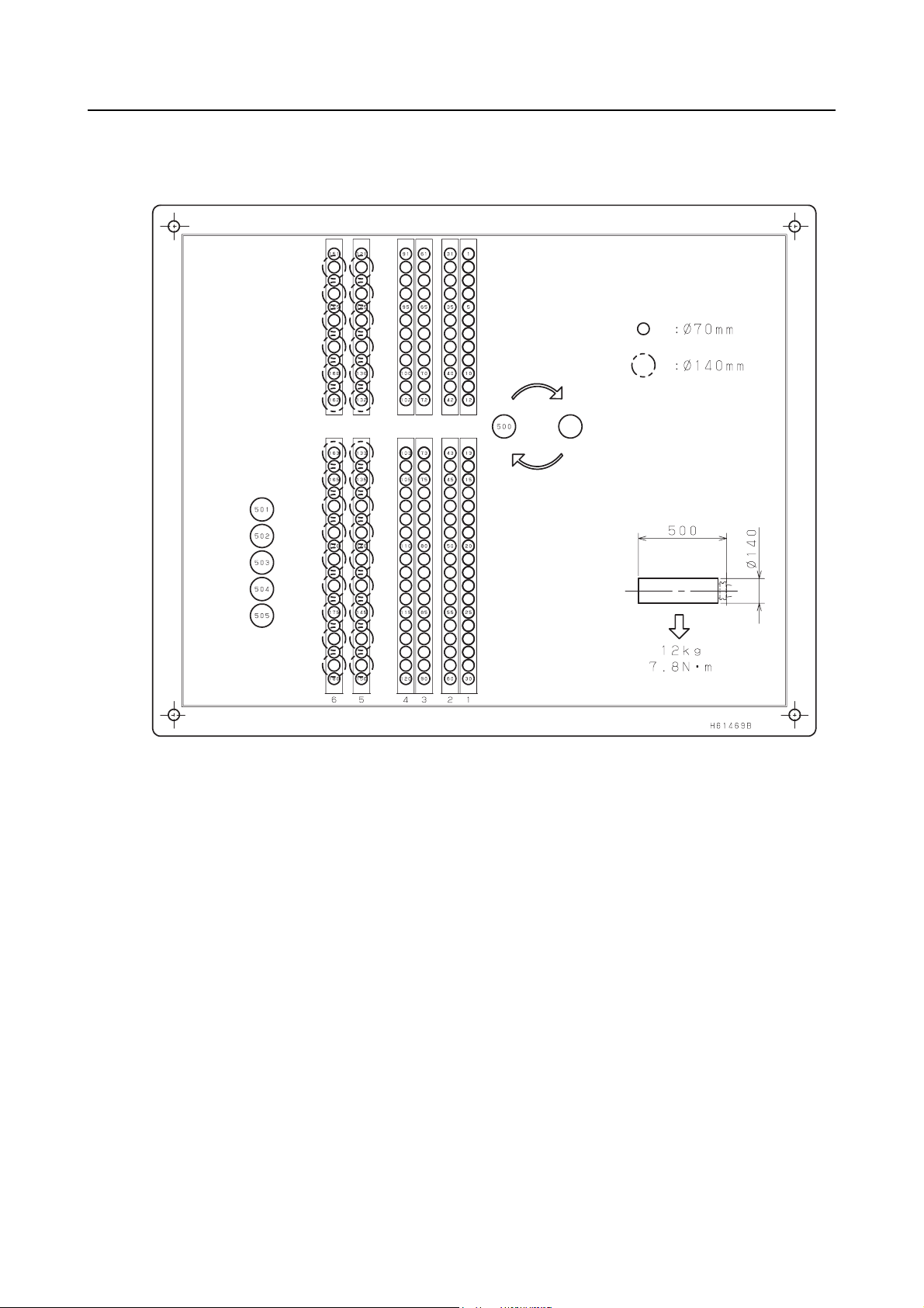
1-2-8 140-tool Magazine for NH6300 DCG
140-tool Magazine for NH8000 DCG . . . . . . . . . . . . . . . . . . . . . . . . . . . P-12
1-2-9 180-tool Magazine for NH6300 DCG
180-tool Magazine for NH8000 DCG . . . . . . . . . . . . . . . . . . . . . . . . . . . P-13
1-2-10 60-tool Magazine for NMH6300 DCG . . . . . . . . . . . . . . . . . . . . . . . . . . P-14
1-2-11 140-tool Magazine for NMH6300 DCG . . . . . . . . . . . . . . . . . . . . . . . . . P-15
1-2-12 180-tool Magazine for NMH6300 DCG . . . . . . . . . . . . . . . . . . . . . . . . . P-16
1-3 Magazine Operation Panel . . . . . . . . . . . . . . . . . . . . . . . . . . . . . . . . . . . . . . . . . P-17
1-3-1 Magazine Mode Selection Button . . . . . . . . . . . . . . . . . . . . . . . . . . . . . P-17
1-3-2 Magazine Indexing Switches . . . . . . . . . . . . . . . . . . . . . . . . . . . . . . . . . P-18
1-3-3 Emergency Stop Button . . . . . . . . . . . . . . . . . . . . . . . . . . . . . . . . . . . . . P-18
1-4 Selecting the Operation Mode (Only in Maintenance Operations) . . . . . . . . . . . P-19
2 OPERATION OF TOUCH PANEL SCREEN . . . . . . . . . . . . . . . . . . . . . . . . . . . . . . . . . P-22
2-1 Magazine Index Operation . . . . . . . . . . . . . . . . . . . . . . . . . . . . . . . . . . . . . . . . . P-23
2-2 Setting-Up of Tools . . . . . . . . . . . . . . . . . . . . . . . . . . . . . . . . . . . . . . . . . . . . . . . P-24
2-3 Self-Diagnosis of the Magazine. . . . . . . . . . . . . . . . . . . . . . . . . . . . . . . . . . . . . . P-28
2-4 Indexing the Magazine Manually . . . . . . . . . . . . . . . . . . . . . . . . . . . . . . . . . . . . . P-29
2-5 Manual Rack Magazine Operation . . . . . . . . . . . . . . . . . . . . . . . . . . . . . . . . . . . P-30
2-6 Recovering Rack Magazine Operation . . . . . . . . . . . . . . . . . . . . . . . . . . . . . . . . P-32
3 SETTING LIGHT TOOLS . . . . . . . . . . . . . . . . . . . . . . . . . . . . . . . . . . . . . . . . . . . . . . . P-34
3-1 Setting the Use-Inhibited Pots . . . . . . . . . . . . . . . . . . . . . . . . . . . . . . . . . . . . . . . P-35

1 RACK MAGAZINE TOUCH PANEL
A rack magazine touch panel provided at the left side of the machine (rack magazine side) is used
to operate the rack magazine.
The switches on the rack magazine touch panel is used for mounting tools in the magazine and
removing tools from it.
P-1
Type
Type 5
Applicable
Magazines
No. 40 taper
tool magazine
No. 50 taper
tool magazine
Magazine Specifications Tool Transfer Method
NH4000 DCG 300 tools
NH5000/40 DCG 180 tools
240 tools
300 tools
NH5000/50 DCG 140 tools
180 tools
NH6300 DCG 60 tools
140 tools
180 tools
NH8000 DCG 60 tools
140 tools
180 tools
NMH6300 DCG 60 tools
140 tools
180 tools
Pot transfer
(without turnover mechanism)

P-2
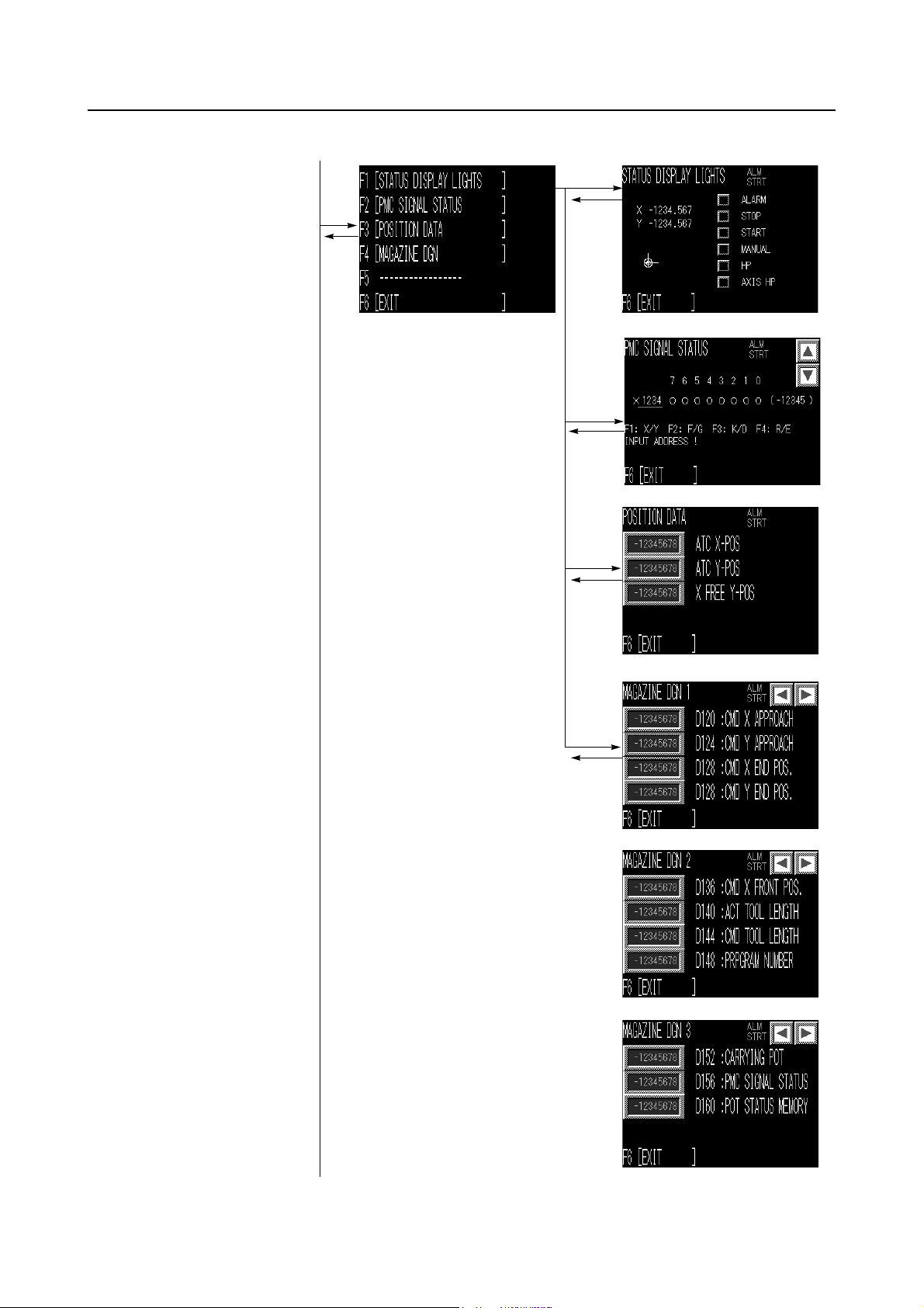
1-1 Transition of Touch Panel Screens
The screens displayed on the touch panel change as follows:
By pressing the [EXIT] (F6) soft-key on the start-up screen displayed immediately after turning the
power ON, the main menu screen is displayed.
By pressing the [TOOL SETUP] (F1) soft-key on the main menu screen, the TOOL RETURN/
CALL screen (the same as the start-up screen displayed immediately after turning the power ON)
is displayed.
Any required screen can be called by pressing the relevant soft-key on the main menu screen.
Main menu screen
Start-up screen displayed immediately
after turning the power ON
F1
F6
[ ]
F6
F4
F6
F1
P-3
F2
F6
F6
F2
F6
F3
F6
F4
F6
P-4
F1
F3
F6
F6
F2
F6
F3
F6
F4
F6
F4
F6
F5
F6

1-2 Tool Pot Layout Diagrams
1-2-1 300-tool Magazine for NH4000 DCG
P-5
(H61582A01)
P-6
1-2-2 180-tool Magazine for NH5000/40 DCG
(H61469B01)

1-2-3 240-tool Magazine for NH5000/40 DCG
P-7
(H61470B01)
P-8
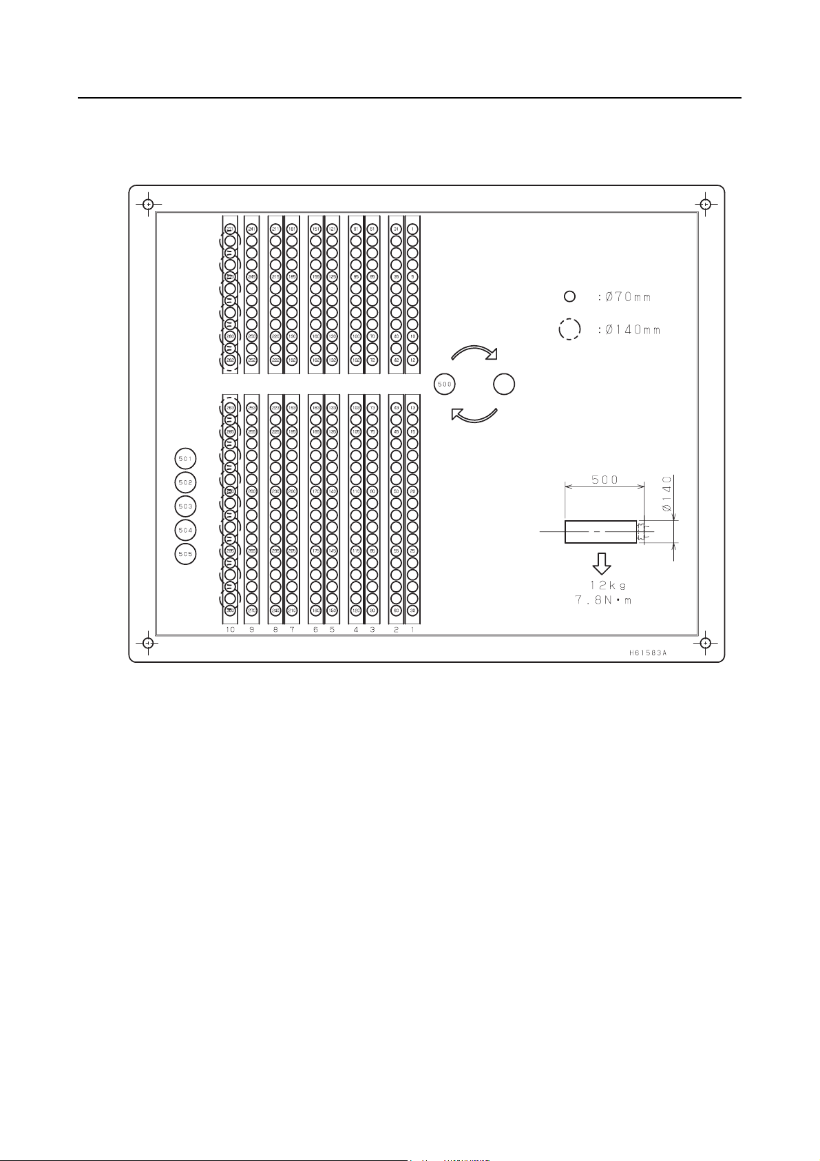
1-2-4 300-tool Magazine for NH5000/40 DCG
(H61583A02)

1-2-5 140-tool Magazine for NH5000/50 DCG
P-9
(H61514A01)

P-10
1-2-6 180-tool Magazine for NH5000/50 DCG
(H61515A01)

1-2-7 60-tool Magazine for NH6300 DCG
60-tool Magazine for NH8000 DCG
P-11
(H61386A04)

P-12
1-2-8 140-tool Magazine for NH6300 DCG
140-tool Magazine for NH8000 DCG
(H61389A04)

1-2-9 180-tool Magazine for NH6300 DCG
180-tool Magazine for NH8000 DCG
P-13
(H61388A03)

P-14
1-2-10 60-tool Magazine for NMH6300 DCG
(H61455A01)

1-2-11 140-tool Magazine for NMH6300 DCG
P-15
(H61456A01)

P-16
1-2-12 180-tool Magazine for NMH6300 DCG
(H61457A01)

1-3 Magazine Operation Panel
1-3-1 "Magazine Mode
Selection Button"
1-3-2 "Magazine Indexing Switches"
1-3-3 "Emergency Stop Button"
P-17
The magazine operation panel is provided on the manual
tool change unit.
The switches on the magazine operation panel is used for
mounting tools in the magazine and removing tools from it.
1-3-1 Magazine Mode Selection Button
The magazine mode selection button is used to determine
whether the magazine is rotated by T commands
(automatic operation) or by manual operation.
Magazine Mode Function
On
Magazine rotation by manual operation is enabled. The button will not light even if it
is pressed during automatic operation.
The magazine can be operated by T commands (in automatic operation). With rack
Unlit
magazine type 5 for No. 50 taper tools, the fixing pin engages in the tool setup
station. The tool setup station can be fixed in position even when it is pulled out for a
tool change operation. Change tools in this status.

P-18
1-3-2 Magazine Indexing Switches
Switch Function
The X- or Y- axis is moved in the negative direction.
The X- or Y- axis is moved in the positive direction.
The magazine indexing switches are used to move the
X- and Y-axes of the magazine.
NOTE
2. The magazine door can be opened during automatic operation. However, if a
T command is read with the magazine door open, automatic operation is stopped by
the magazine door interlock function.
3. The magazine cannot be rotated manually during automatic operation.
1. Close the magazine door before moving the magazine axes.
CAUTION
Be aware that the magazine will start rotating if the magazine indexing switch
(counterclockwise) or (clockwise) is pressed by mistake while the JOG,
STEP or ZRN mode is selected. Take care not to press the magazine indexing switch
(counterclockwise) or (clockwise) by mistake. If you do this, you could be
caught by the magazine.
1-3-3 Emergency Stop Button
The EMERGENCY STOP button has the same function
as that available with the EMERGENCY STOP button on
the machine operation panel.
Pressing the EMERGENCY STOP button on the
magazine operation panel turns off the power to the
circuits that control the axis movements and spindle
rotation, stopping the machine as well as magazine
operation.
The operator must be able to press this button any time at
any place while operating the machine.

P-19
The status display lights at the touch panel indicate the rack magazine status as indicated below.
Status Display Lights Status
ALARM Lights (red) if an alarm occurs.
STOP Lights (red) in the feed hold state.
START Lights after cycle start.
MANUAL Lights when the manual mode is selected for the rack magazine.
HP Lights when all axes are at the home position.
AXIS HP
Lights when the X- and Y-axes of the magazine are in the specified
operation enabled range.
"X" and "Y" are displayed when the X- and Y-axes are at the zero
point.
1-4 Selecting the Operation Mode (Only in Maintenance Operations)
When operating the rack magazine, first press the axis selection switches and
simultaneously to change the NC screen to path system 2. Display the OPERATOR'S PANEL
screen and select the operation mode of the rack magazine.
Select the operation mode of the rack magazine by following the steps below.
1) Press the function selection key (SETTING).
SETTING
2) Press the menu selection key .
3) Press the [OPERAT PANEL] soft-key.
The mode selection items are displayed at the screen.
4) Select the operation mode using the cursor control keys.

P-20
Operation Mode Explanation
To input parameters MDI To input the parameters, set "VALID" for "PARAMETER WRITE" on
the SETTING screen.
If the PS100 alarm occurs, press the (RESET) key while
holding down the (CAN) key. The alarm will be cleared.
To output parameters MDI
To move an axis in
handle feed operation
STEP <Operation procedure>
1) Select the manual mode for magazine operation
(the indicator will light).
2) Display the "HANDLE/STEP FEED" screen on the touch
panel.
The operation mode is automatically selected as the touch
panel screen changes.
3) Set the axis to be moved and the feed amount using "AXIS"
and "HANDLE MULT." on the screen.
Horizontal axis direction: Select the X-axis.
Vertical axis direction: Select the Y-axis.
4) Press the magazine indexing switch to move the axis.
+ direction: Magazine indexing switch
(counterclockwise)
− direction: Magazine indexing switch (clockwise)
5) After moving axes, press the [EXIT] soft-key (F6) to exit the
screen.
1. Unless the screen is exited, the mode stays as it is
NOTE
(STEP).
2. Use this function only for return operations. Please
note that no interlock is imposed.

Operation Mode Explanation
To move an axis in
JOG feed operation
To return an axis to
the zero point
JOG or ZRN
Before moving an axis in JOG feed operation or returning
NOTE
an axis to the zero point, make sure that the conditions
below are satisfied.
1. The manual mode is selected for magazine
operation.
2. The magazine is not operating.
<Operation procedure>
1) Display the "JOG FEED" or "ZERO RETURN" screen on the
touch panel.
The operation mode is automatically selected as the touch
panel screen changes.
P-21
2) Select the axis to be moved and press the button for the
direction in which the axis is to be moved.
Horizontal axis direction: Select the X-axis.
Vertical axis direction: Select the Y-axis.
3) Press the magazine indexing switch to move the axis.
+ direction: Magazine indexing switch
(counterclockwise)
− direction: Magazine indexing switch (clockwise)
4) After moving axes, press the [EXIT] soft-key (F6) to exit the
screen.
1. Unless the screen is exited, the mode stays as it is
NOTE
(JOG or ZRN).
2. Use this function only for return operations. Please
note that no interlock is imposed.
Change pages within the "HANDLE/STEP FEED", "JOG FEED" or "ZERO RETURN"
NOTE
screen using the page selection keys and .

P-22
2 OPERATION OF TOUCH PANEL SCREEN
By pressing the [EXIT] (F6) soft-key on the start-up screen displayed immediately after turning the
power ON, the main menu screen, shown below, is displayed.
If the tool transfer arm is positioned at the standby position, the arm moves from the standby
position to the magazine side position when the manual mode is selected. If the arm is holding a
tool, it returns this tool to the magazine temporarily. The arm moves to receive the temporarily
returned tool when the manual mode is turned OFF. The arm does not receive a tool if an
emergency stop or an alarm has occurred during the manual mode of magazine operation.
F1: TOOL SETUP
This function calls the specified tool from the pot to the tool setup position or returns the tool
from the tool setup position to the specified pot. Usually, this screen opens when the power
is switched ON.
F2: DIAGNOSTIC
This function displays the internal status of the magazine, PMCDGN, and some other data
set in the machine.
For example, the screen allows you to check information like the pot number of the tool
being transferred if the magazine has stopped due to an emergency stop.
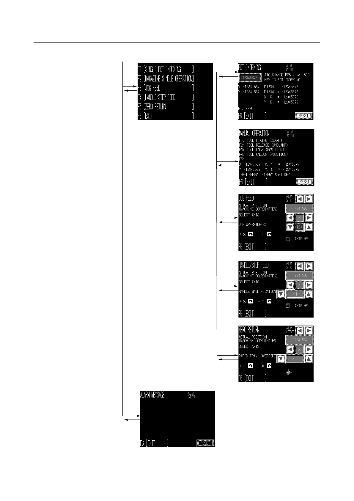
F3: MANUAL OPERATION
Used for recovering magazine operation. This function allows manual pot indexing, manual
magazine operation, JOG/STEP feed operation, and so on.
F4: ALARM MESSAGE
Displays PMC alarm messages.
F5: -----
Not used.

2-1 Magazine Index Operation
When the magazine index command is executed, the rack magazine operates in the sequence
shown below.
Start (ATC standby position)
Positioning of X- and Y-axes (Positioning at the return pot)
Tool release (The tool is unlocked) (Pot released)
Positioning of X- and Y-axes (Positioning at the specified pot)
Tool fixing (The tool is locked) (Pot clamped)
Positioning of X- and Y-axes
(Positioning at the ATC standby position)
P-23
Completion (ATC standby position)

P-24
2-2 Setting-Up of Tools
On machines equipped with a rack magazine, the tool setup pot (tool change position) is located
at the lower right of the rack magazine.
The setup pot is used for storing and removing tools at the rack magazine. When storing a tool in
the rack magazine, mount a new tool in the setup pot; it will be transported to the specified pot.
When removing a tool from the rack magazine, specify the pot number of the tool to be removed to
call it to the setup pot.
Storing a Tool
Calling a Tool
Pot No.
501
502
503
504
505
*
*
*
*
NOTE
*
Five tool setup positions, Nos. 501 to 505, are provided with NH4000 DCG and
NH5000/40 DCG machines that are equipped with a 300-tool magazine.

P-25
1) Select the magazine manual operation mode by
pressing the magazine mode selection button.
The magazine mode selection button lights.
When there is a tool at ATC standby position, the
tool is returned to the magazine.
By selecting automatic mode after finishing the
setup operation, the returned tool is loaded again
and then the operation mode changes to automatic
mode.
2) Display the main menu screen on the touch panel.
TOOL RETURN/CALL Screen
3) Press the [TOOL SETUP] (F1) soft-key on the
screen.
The TOOL RETURN/CALL screen is displayed.
4) There are two ways of selecting a pot number.
• Press the area where a pot number
is displayed. The keyboard will then be
displayed on the touch panel screen for input
of a pot number. Input the pot number of the
tool to be mounted or removed and press the
[ENT] key. The set pot number is displayed.
• Press [POT NO.]. A screen for selecting a pot
number will be displayed. Press inside the
frame of the required tool number. The pot
number of the selected tool is displayed.
• [+] increases the pot number by one and [−]
decreases the pot number by one.

P-26
Pot No. entry keyboard screen
Pot No. selection screen
NOTE
machines equipped with a 300-tool
magazine, tool Nos. 501 to 505 can be
selected on the TOOL RETURN/CALL
screen using the page selection keys
and .
2. When a pot number is input for POT NO.,
the tool number registered for the pot at the
TOOL REGISTRATION screen is displayed
at TOOL NO. To change the displayed tool
number, follow the steps below.
a) Press the area of the tool
number to be changed and input the
desired tool number.
b) Press the [WRITE] soft-key (F3).
If a new tool number can be assigned, the tool
number registered at the TOOL REGISTRATION
screen is changed accordingly. If the tool number
cannot be changed, it returns to the previously
displayed number.
1. With NH4000 DCG and NH5000/40 DCG
The following symbols displayed on the
screen denote meanings as below.
TB: Broken tools
∗: Tools used to the preset life
#: Skip tools
: Help key
Pressing this key displays the
description of the TB, ∗ and #.
The description is cleared by
pressing the key again.
: Page selection key
5) To store a tool in the rack magazine, press the
[RETURN] soft-key (F1). To call a tool from the rack
magazine, press the [CALL] soft-key (F2).
1. When the tool is stored, the set value of the
NOTE
pot number becomes "0".
2. With NH4000 DCG and NH5000/40 DCG
machines equipped with a 300-tool
magazine, pressing the [RETURN] or
[CALL] soft-key will return the tools to/call
the tools from all five tool set up pots.
6) Open the magazine door.
7) Mount/remove the tool.
With rack magazine type 5 for No. 50 taper tools,
turn the magazine manual operation mode OFF to
engage the fixing pin before removing or mounting a
tool.

P-27
NOTE
1. Even if no tool is stored in the magazine pot,
always specify the return operation after
calling a tool.
On completion of calling, "CALL FIN. (0/1) =
1" is displayed on the screen. In this state,
the pot number cannot be changed.
After the completion of the tool return
operation, "CALL FIN. (0/1) = 0" is displayed
on the screen. In this state, the return
command cannot be executed.
2. To set tools in the magazine consecutively, it
is necessary to perform repeated tool return
operations. To make this possible, "CALL
COMPLETE (0/1)" has to be set to "0" after
setting the pot number.
To change the setting of "CALL COMPLETE
(0/1)", press the [CALL COMPLETE (0/1)]
(F4) soft-key. Perform this operation with
due care because interference will occur if
there is a tool in the pot to which the tool is
to be returned.
3. If the tool number is specified with the pot
number set to "0", a search will be
conducted for the appropriate tool pot and
the specified tool number will be set for that
tool pot.
<Example>
Pot No.
000
Pot No.
Search
Pot No.
123
Initial
conditions
Automatically
set
Too l N o .
0000
Too l N o .
1001
Too l N o .
1001
If an appropriate tool pot is not found, the tool
number is set and the pot number is left as "0".
Specify a
number

P-28
2-3 Self-Diagnosis of the Magazine
The MAGAZINE DGN screens display the internal status of the magazine. These screens are not
used in normal operation.
For example, one of the screens allows you to check information like the pot number of the tool
being transferred if the magazine has stopped due to an emergency stop.
The pot number of the tool being transferred is displayed at "CARRYING POT".
• When a tool is in the spindle
When the next tool is called, the pot for the spindle tool at the standby position is temporarily
returned to the empty pot storage position*, and "D160 :POT STATUS MEMORY" is turned
to "1". When "D160 :POT STATUS MEMORY" is already set to "1", an alarm "EX3211 POT
FOR SPINDLE TOOLS AVAILABLE." is displayed. When a pot is in the empty pot storage
position*, remove the pot and set "D160 :POT STATUS MEMORY" to "0".
• When tools are in the spindle and in the standby position
When the next tool at the standby position is returned to the magazine by T0, the pot for the
spindle tool - which has been temporarily returned to the empty pot storage position* - is
called to the standby position again, and "D160 :POT STATUS MEMORY" is turned to "0".
When "D160 :POT STATUS MEMORY" is already set to "0", an alarm "EX3210 NO POT
FOR SPINDLE TOOLS." is displayed. When no pot is in the empty pot storage position*,
mount a pot on the empty pot storage position* and set "D160 :POT STATUS MEMORY" to
"1". If mounting a pot is difficult, remove the spindle tool, delete the spindle tool data on the
TOOL REGISTRATION screen, and set "D160 :POT STATUS MEMORY" to "0".
*
NOTE
The empty pot storage position is as follows.
60-tool specifications: No. 60
140-tool specifications: No. 140
180-tool specifications: No. 180
240-tool specifications: No. 240
300-tool specifications: No. 300

2-4 Indexing the Magazine Manually
The POT INDEXING screen displayed at the touch panel is used to index the magazine manually.
P-29
NOTE
move axes in JOG or STEP feed operation.
2. Use the manual magazine indexing function only for recovery operations.
3. Take care when performing a recovery operation using JOG feed because the
interference check function will not be operating.
"Pot index" means the operation to positioning the X- and Y-axes in front of the specified pot
number.
1) Select the magazine manual operation mode by
pressing the magazine mode selection button.
The magazine mode selection button lights.
2) Display the main menu screen on the touch panel.
3) Display the POT INDEXING screen. Press the
[MANUAL OPERATION] (F3) and [SINGLE POT
INDEXING] (F1) soft-keys in this order.
1. The magazine indexing switches (clockwise and counterclockwise) are used to
4) Press the area where a pot number is
displayed. The keyboard will then be displayed on
the touch panel screen for input of a pot number.
Input the pot number to be indexed.
5) Press the [ENT] key.
The pot number is set and the tool number currently
set for that pot number is displayed.
6) Press the [EXEC] soft-key (F1).
The axes are positioned at the set pot number position.
Positioning is performed in different ways
NOTE
depending on whether or not there is a tool at the
next tool position.
1. The existence of a tool at the next tool
position is judged by the tool status (tool
fixed or tool released).
2. The tool change position for the ATC is pot
No. 500. For tool change operation, the tool
change position is the same as position of
the input pot No.
7) After completing pot indexing operation, press the
[EXIT] soft-key (F6).

P-30
2-5 Manual Rack Magazine Operation
To operate the rack magazine manually, use the rack magazine touch panel at the rack magazine
side.
NOTE
ZRN) after pot indexing. (When the MANUAL OPERATION screen is displayed, the
operation mode automatically switches to STEP mode.)
2. Perform manual rack magazine operation for the purposes of a recovery operation
only.
3. Take care when performing a recovery operation using JOG feed because the
interference check function will not be operating.
The manual magazine operation procedure is described below.
<Example: No. 50 taper tool (type 5)>
Rack side
1. Perform single rack magazine operations in a manual operation mode (STEP, JOG,
TOOL UNLOCK
TOOL LOCK
TOOL FIXING
(CLAMP)
TOOL RELEASE
(UNCLAMP)
1) Carry out pot indexing.
P-29 page (2-4)
2) Press the [EXIT] soft-key (F6).
3) Press the [MAGAZINE SINGLE OPERATION] soft-
key (F2).

The MANUAL OPERATION screen is displayed.
4) Press the soft-key (F1 to F5) for the required
operation.
The rack magazine performs the selected
procedure.
5) Press the [EXIT] soft-key (F6) after the manual
operation is completed.
<Rack magazine operating conditions (interlocks) for manual operation>
In order to avoid interference, the following operating conditions (interlocks) are provided for each
manual operation of the rack magazine
Please take care during the return operation because the following interlocks may be
NOTE
bypassed in some cases to enable the operation.
P-31
<Type 5>
No. Operation
1 TOOL FIXING Tool transport device clamps pot
Without operating conditions (interlocks)
2 TOOL RELEASE
Tool transport device unclamps pot
Tool transport device in tool lock position
3 TOOL LOCK
Tool transport device moves from pot indexing position to rack side
Tool transport device in tool indexing position
4 TOOL UNLOCK
Tool transport device moves from rack side to pot indexing position
Tool transport device in the tool lock position
*
NOTE
The interlock can be bypassed by canceling the ATC interlock at the ATC MANUAL
screen displayed on the NC operation panel.
Explanation
Interlock
*
*
*

P-32
2-6 Recovering Rack Magazine Operation
If the rack magazine stops part way through, follow the procedure below to recover the magazine
operation (tool transfer axis, sensor axis).
Check that the JOG or HND/STEP mode is selected on the touch panel, and perform a recovery
operation first using STEP feed operation. After the completion of the recovery operation, the
"AXIS HP" (magazine X-/Y-axes in the operation enabled range) lights on the screen.
If the tool transport device is holding a tool, display the POT INDEXING screen for the rack
magazine and execute the SINGLE POT INDEX operation. After that, display the MANUAL
OPERATION screen for the rack magazine, and carry out the recovery procedure.
CAUTION
After recovering the rack magazine operation, always check the tool data of the tool in
the spindle and the standby tool on the TOOL REGISTRATION screen. If the tool data
on the screen does not agree with the actual tools, the tool could fall or strike the
workpiece or other trouble could occur.
Note in particular that if the screen displays "no standby tool" although there is a
standby tool present, the tool will fall.
<Recovery operation using STEP feed operation (tool transfer axis)>
If the tool transfer axis motion fails part way through, recover the operation using a STEP feed
operation.
When using JOG feed operation for the recovery operation, set the feedrate override at
NOTE
the lowest setting.
After the completion of the recovery operation, the "AXIS HP" (magazine X/Y-axes in the operation
enabled range) lights on the screen.
Usually, the axes enter the operation enabled range when the X-axis is moved to the center
between the magazine columns.
1) Display the main menu screen on the touch panel.
2) Display the HANDLE/STEP FEED screen.
Press the [MANUAL OPERATION] (F3) and
[HANDLE/STEP FEED] (F4) soft-keys in this order.
3) Check that the coordinate value changes in
response to one-pulse input. Then, select a larger
magnification ratio with the axis feed amount
selection switch and feed the X-axis.
The X-axis has reached the operation recovery
position when the "AXIS HP" (magazine X/Y-axes in
the operation enabled range) lights on the screen.

4) Display the MANUAL OPERATION screen and
carry out the remaining steps necessary for the
recovery operation.
P-33
NOTE
1. If a pot indexing operation is necessary,
specify the pot indexing data and execute
"MAGAZINE SINGLE OPERATION".
2. The magazine door cannot be opened in the
STEP mode (pulse handle mode).
3. JOG feed operation can be used for a
recovery operation in which long axis
movements are made. In such a case, set
the feedrate override at the lowest setting.

P-34
3 SETTING LIGHT TOOLS
Tools classified as "light" can be set at the TOOL REGISTRATION screen displayed on the NC
operation panel.
1) Press the function selection key (OFFSET).
OFFSET
2) Press the [TOOL REGIST.] soft-key.
The TOOL REGISTRATION screen will be displayed.
3) Using the cursor control keys, move the cursor to the tool number of the tool to be set as a
light tool.
The setting is necessary for every tool number of the light tools.
NOTE
4) Press the [TOOL DETAIL] soft-key.
The TOOL DETAILS field is displayed.
5) Select "LIGHT TOOL" using the [DETAIL UP] or [DETAIL DOWN] soft-key.
6) Press the [SET] soft-key.
"VALID" is highlighted and the tool specified on the screen of the TOOL REGISTRATION
screen is registered as a light tool.
The setting items on the TOOL REGISTRATION screen are described below.
NOTE
Item Explanation
LIGHT TOOL
Set "VALID" for the light tools for which high-speed ATC
operation is possible.
FACE CONTACT This item is used only for two-face constrained tools.
"VALID" is displayed when the tool is called to the tool setup
SETUP TOOL
position.
"INVALID" is displayed when the tool is returned to the
magazine pot from the tool setup position.
"VALID" is displayed if the tool is judged to be broken at the
BREAKAGE TOOL
rack magazine. "INVALID" is displayed when the tool is called
to the tool setup position.
(Tool breakage detection specifications)
If the tool in the setup state (SETUP TOOL: "VALID") is specified using a T code,
the following alarm occurs.
"EX0201 IMPROPER T-CODE SPECIFIED"
If a tool judged to be broken (BREAKAGE TOOL: "VALID") is specified using a T code,
the following alarm occurs (tool breakage detection specifications).
"EX0201 IMPROPER T-CODE SPECIFIED"
7) After completing the setting for light tools, press the [RETURN] soft-key.
The screen returns to the screen of the TOOL REGISTRATION screen.
The pot numbers of the tools for which "VALID" is selected in the TOOL DETAILS field are
highlighted in green.
If both the spindle tool and the next tool are light tools, the ATC operates at a high speed.
NOTE
In other cases, the ATC operates at a low speed.

3-1 Setting the Use-Inhibited Pots
With the rack magazine specification, the pots next to the one where a large diameter tool is
stored must be left empty. To avoid returning a tool to such pots accidentally, use-inhibited pots
can be set. Make this setting using the function keys on the NC operation panel.
1) Set the machine in the emergency stop state.
P-35
2) Press the function selection key (SETTING).
SETTING
3) Set "VALID" for "PARAMETER WRITE" on the SETTING screen.
4) After pressing the function selection key (SYSTEM), press the menu selection key
SYSTEM
several times to display the [PMC MAINTE] soft-key.
5) Press the [PMC MAINTE] soft-key.
6) Press the [(OPRT)] soft-key to display the [SWITCH PMC] soft-key.
7) Press the [SWITCH PMC] soft-key to switch the screen to "2ND PMC "
8) Press the [ZOOM] soft-key.
9) After pressing the data input key , press the [G-SRCH] soft-key.
7
A
The screen displays the data from D2800 onward.

P-36
10) Using the page selection keys and the cursor control keys, display the data for D (2800 + pot
number).
11) Make the necessary pot settings.
Use-inhibited pots: Set "0".
<Example>
To set pot No. 6 as a use-inhibited pot
D2806 = 0
12) Set the machine in the emergency stop state again.
13) Press the function selection key (SETTING).
SETTING
14) Set "INVALID" for "PARAMETER WRITE" on the SETTING screen.
15) Turn off the power and then turn it on again.
This completes the pot setting.
On shipping, a number other than 0 is set for all pot data. To set a pot as a use-inhibited
NOTE
pot, "0" must be explicitly set as the pot data.

Comment Form
To improve this manual, we invite you to make comments on any insufficient description or errors in this
manual. We want to know how you think we can make this manual better. Please restrict your comments to
those concerning this manual only. Comments can also be submitted using the company website at
http://www.moriseiki.com.
Name of Manual RACK MAGAZINE TOUCH PANEL OPERATION MANUAL
Number of Revisions OM-NHRACKTP-A0E (2006.12)
Name Company
Department Telephone
Address
Chapter Page Line Comments/Requests
Date:
For Mori Seiki's Use - Do not write below this line.
Description Reception No. Received by

http://www.moriseiki.com
MORI SEIKI CO., LTD.
Nagoya Head Office
Nara Campus
Iga Campus
Chiba Campus
2-35-16 Meieki, Nakamura-ku, Nagoya City, Aichi 450-0002, Japan
Phone: (052) 587-1811 Fax.: (052) 587-1818
362 Idono-cho, Yamato-Koriyama City, Nara 639-1183, Japan
Phone: (0743) 53-1121
106 Kita Koriyama-cho, Yamato-Koriyama City, Nara 639-1160, Japan
Phone: (0743) 53-1125
201 Midai, Iga City, Mie 519-1414, Japan
Phone: (0595) 45-4151
488-19 Suzumi-cho, Funabashi City, Chiba 274-0052, Japan
Phone: (047) 410-8800
MORI SEIKI U.S.A., INC.
Head Office
Administrative Department
Technical Centers
Representative Office
5655 Meadowbrook Drive, Rolling Meadows, Illinois 60008
Phone: (1)-847-593-5400 Fax.: (1)-847-593-5433
2100 Golf Road Suite 300, Rolling Meadows, Illinois 60008
Phone: (1)-847-290-8535 Fax.: (1)-847-290-5500
Chicago, Dallas, Los Angeles, Detroit, Cincinnati, Boston, New Jersey
Charlotte, San Francisco
MORI SEIKI MEXICO, S.A. DE C.V.
Head Office & Technical Center
Montecito 38 Piso 12-38 Col. Napoles 03810 México D.F.
Phone: (52)-55-9000-3276 Fax.: (52)- 55-9000-3279
MORI SEIKI BRASIL LTDA.
Head Office & Technical Center
Rua República do Iraque, 1432 2 and, Campo Belo 04611-002 São Paulo - SP, Brasil
Phone: (55)-11-5543-1762 Fax.: (55)-11-5543-1948
MORI SEIKI ESPAÑA S.A.
Head Office & Technical Center
Calle de la Electrónica, Bloque B, Nave 9 Poligono Industrial "La Ferreria" 08110
Montcada I Reixac (Barcelona), Spain
Phone: (34)-935-75-36-46 Fax.: (34)-935-75-08-47
MORI SEIKI SINGAPORE PTE LTD
Head Office & Technical Center
Technical Center
3 Toh Guan Road East, Singapore 608835
Phone: (65)-6560-5011 Fax.: (65)-6567-6234
MALAYSIA BRANCH
MORI SEIKI (THAILAND) CO., LTD.
Head Office & Technical Center
119/2 Moo 8, Bangnathani Building 1st Floor A1, Bangna-Trad KM.3 Road Kwaeng
Bangna, Khet Bangna, Bangkok 10260, Thailand
Phone: (66)-2-361-3700-5 Fax.: (66)-2-361-3706
MORI SEIKI (TAIWAN) CO., LTD.
Head Office & Technical Center
No. 8, Kong 8th Road, Linkou No. 2 Industrial District, Linkou Hsiang, Taipei Hsien,
Taiwan, R.O.C.
Phone: (886)-2-2603-1701 Fax.: (886)-2-2603-1706
MORI SEIKI HONG KONG LIMITED
Head Office & Technical Center
Unit 02, 8/F., Vicwood Plaza, 199 Des Voeux Road, Central, Hong Kong
Phone: (852)-2757-8910 Fax.: (852)-2757-7839
MORI SEIKI (SHANGHAI) CO., LTD.
Head Office
Technical Center
Room 4301, 4307, Maxdo Center, No.8 Xing Yi Rd., HongQiao Development Zone,
Shanghai 200336, China
Phone: (86)-21-5208-0270 Fax.: (86)-21-5208-0273
Shanghai, Beijing, Tianjin, Dalian, Shenzhen, Chongqing, Guangzhou
MORI SEIKI GmbH
Head Office
Technical Centers
Antoniusstrasse 14, 73249 Wernau, Germany
Phone: (49)-7153-934-0 Fax.: (49)-7153-934-220
Stuttgart, Istanbul, Prague, München, Hamburg, Düsseldorf
MORI SEIKI (UK) LTD.
Head Office
Technical Centers
Representative Office
202 Bedford Avenue, Slough SL1 4RY, England
Phone: (44)-1753 526518 Fax.: (44)-1753 524695
London, Birmingham
Leicester
MORI SEIKI FRANCE S.A.S.
Head Office & Technical Center
Technical Centers
Parc du Moulin, 1 Rue du Noyer BP 19326 Roissy en France 95705 Roissy CDG
Cedex, France
Phone: (33)-1-39-94-68-00 Fax.: (33)-1-39-94-68-59
Toulouse, MS SYFRAMO S.A.S.
MORI SEIKI ITALIANA S.R.L.
Head Office & Technical Center
Via Riccardo Lombardi N. 10, 20153 Milano, Italy
Phone: (39)-02-4894921 Fax.: (39)-02-48914448
MORI SEIKI KOREA CO., LTD.
Head Office & Technical Center
A-101, 2 SK TWIN TECH TOWER, 345-9 Kasan-dong, Kumcheon-Ku, Seoul,
Korea
Phone: (82)-2-862-0925 Fax.: (82)-2-862-0928
PT. MORI SEIKI INDONESIA
Head Office & Technical Center
Komplek Gading Bukit Indah Blok M/01 J1. Bukit Gading Raya, Kalapa Gading,
Jakarta Utara, 14240 Indonesia
Phone: (62)-21-453-1199 Fax.: (62)-21-4585-7414
MORI SEIKI CO., LTD. India Branch
Head Office & Technical Center
India Branch: 404 A World Trade Centre, Babar Rd. Connaught Place,
Phone: (91)-11-4152-8520 Fax.: (91)-11-4152-8530
New Delhi - 110001, India
MORI SEIKI AUSTRALIA PTY LTD
Head Office
Technical Centers
6/6 Garden Road Clayton VIC 3168, Australia
Phone: (61)-3-8545-0900 Fax.: (61)-3-9561-4999
Melbourne, Sydney
The export of this product is subject to an authorization from the government of the exporting country.
Check with the government agency for authorization.
Printed in Japan
06 1110
 Loading...