

Page 1
10/100 Ethernet Converter
200750-xxxxx and 200910-xxxxx
OEM Board Version
Users’ Manual
And
Installation Guide
(Rev. G)
February 10, 2011
Moog Components Group
Springfield Operations
750 West Sproul Road
Springfield, PA 19064
E-Mail: mcg@moog.com URL: www.moog.com/components
Tel: 610-328-4000 Fax 610-605-6216
24/7 Technical Customer Support Hotline: 610-605-6101
Page 2

Moog Components Group 10/100 Ethernet Converter Manual February 10, 20011
1 10/100 Ethernet Converter P/N – 200750-xxxx/200910-xxxx Overview ........................................................................ 3
1.1 Manual Revision History: ........................................................................................................................ 4
1.2 10/100 Ethernet Converter Revision History: .......................................................................................... 4
1.3 10/100 Ethernet Converter Dash (-) Number Definitions: ....................................................................... 5
1.4 Operation ................................................................................................................................................. 7
1.4.1 10/100 Ethernet Converter Indicators, Controls and Connectors: .................................................................... 7
1.4.2 10/100 Ethernet Converter Specifications: ....................................................................................................... 9
1.4.3 10/100 Ethernet Converter Signals During Operation ................................................................................... 10
2 General 10/100 Ethernet Converter Installation Notes .................................................................................................. 11
2.1 Standalone 10/100 Ethernet Converter Installation Checkout Procedure .............................................. 11
2.2 10/100 Ethernet Converter with Motherboard Installation Checkout Procedure ................................... 12
Page 2 of 12
Page 3
Moog Components Group 10/100 Ethernet Converter Manual February 10, 20011
1 10/100 Ethernet Converter P/N – 200750-xxxx/200910-xxxx
Overview
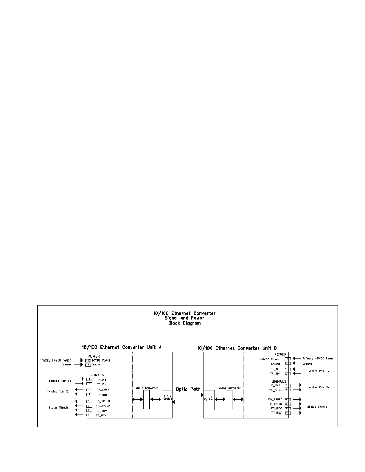
The PRIZM 10/100 Ethernet Converter provides completely transparent media conversion between
10/100 Mbps, Full/Half Duplex Twisted Pair and fiber optic Ethernet. Two units are required to form a
complete data link. Twisted Pair Ethernet data is converted to fiber at one end of the link, and then
converted back to Twisted Pair at the other end to provide a seamless Ethernet connection. The
converters allow negotiation between both ends of the link to the highest commonly supported data rate.
A 1x9 fiber optic transceiver module with a single-mode source laser (typically 1310 or 1550nm
wavelength) and either an integral or external wave division multiplexer (WDM) are used to allow for
single fiber operation. It should be noted that the boards at either end of the link are functionally
identical, however the optical transceiver on each board must have a different transmit wavelength than
the transceiver at the opposite end of the link when single fiber operation is desired.
The Ethernet converters are supplied in two basic form factors. The first (200750-xxxx) is for spaceconfined applications and requires +5VDC. The dimensions of this version of the converters are 2” wide
x 3” long x .7” high. Six mounting holes are supplied for ease of installation. This unit provides a 2x5
interface connector that can be either soldered to directly, or populated with a standard data header for
easy wiring. In addition to four pins for Ethernet twisted pair data (TD+/-, RD+/-), the header contains
four pins for the monitoring of status signals (data traffic and negotiated data speed at both the twisted
pair and fiber interface). The final two positions on the connector are reserved for supplied +5VDC (.5
Amp max) and digital ground. The +5VDC input to the board is unfused, but the board is protected by a
reversed diode, D1 in case power is accidentally reversed to the board.
The second form factor (200910-xxxx) is slightly larger: 2.6” wide x 3.5” long x 0.9” high. Four
mounting holes are supplied on this board. This form factor is currently supplied in both +12VDC and
+24VDC versions. These units are supplied with an industry standard RJ-45 connector for the Ethernet
interface as well as individual LED indicators to display the state of the four status signals described
previously. A typical block diagram for these form factors is shown in Figure 1 below.
Page 3 of 12
Page 4

Moog Components Group 10/100 Ethernet Converter Manual February 10, 20011
1.1 Manual Revision History:
The manual has gone through the following revisions:
Original Demonstration Units
Rev A Describes Alpha Production Units
Rev B Included dash numbers for +12VDC powered units
Rev C Aligned Manual for new part numbering scheme
Rev D Updated product revisions and corrected various documentation errors
Rev F Updated contact information to reflect Moog Components Group.
1.2 10/100 Ethernet Converter Revision History:
The 10/100 Ethernet Converter (200750-xxx) has gone through the following printed circuit board (PCB)
and Assembly revisions:
PCB Revision A/Assembly Revision A Demonstration Boards
PCB Revision A/Assembly Revision B Alpha Production Units – Set up for Integral WDM and
+3.3V, extended temperature range optics
PCB Revision B/Assembly Revision C Revision B of the PCB and corresponding assembly
changes- Production Units
The 10/100 Ethernet Converter (200910-xxx) has gone through the following printed circuit board (PCB)
and Assembly revisions:
PCB Revision A/Assembly Revision A Demonstration Boards/ Alpha Production Units – Set up
for Integral WDM and +3.3V, extended temperature
range optics
PCB Revision B/Assembly Revision A Revision B of the PCB and corresponding assembly
changes
Page 4 of 12
Page 5

Moog Components Group 10/100 Ethernet Converter Manual February 10, 20011
1.3 10/100 Ethernet Converter Dash (-) Number Definitions:
Over the course of their product life, both incarnations of the 10/100 Ethernet Converter have
undergone changes in the way part numbers are assigned. On older boards, a dash and three-digit
number followed the base number, while on newer revisions; a dash and four digits follow the base
part number. The dash numbers identify the specific board configurations:
Legacy 200750-XXX
-001 +5V standard optics (1310nm laser) with integral WDM, demonstration unit
-002 +5V standard optics (1550nm laser) with integral WDM, demonstration unit
-003 +3.3V extended temperature optics (1310nm laser) with integral WDM and 2x5 pin header
-004 +3.3V extended temperature optics (1550nm laser) with integral WDM and no placed header
-005 +3.3V extended temperature optics (1550nm TX) with integral WDM and 2x5 pin header and
no buffer on status pins
-006 +3.3V extended temperature optics (1310nm TX) with integral WDM and 2x5 pin header and
no signal buffer on status pins
-007 Manually rounded corners. +3.3V extended temp optics (1310nm TX) with integral WDM and
2x5 pin header
-008 Manually rounded corners. +3.3V extended temp optics (1550nm TX) with integral WDM and
2x5 pin header
-009 +5V ext. temp (1310nm TX), integral WDM soldered to board. 2x5 data header not placed.
-010 +5V ext. temp. (1550nm TX), integral WDM soldered to board. 2x5 data header not placed.
200750-ABCD
A 1: 5VDC B: 1310nm C: SM, single fiber D: ST connector E; Misc
2: 12VDC 1550nm SM, dual fiber SC connector
3: 24VDC MM, dual fiber
.
Legacy 200910-XXX
-001 +12V supply voltage, 1310nm SM TX with integral WDM. RJ45 placed.
-002 +12V supply voltage, 1550nm SM TX with integral WDM. RJ45 placed.
-003 +9V supply voltage, 1310nm TX with socketed SC, SM, RJ45 placed
-004 +9V supply voltage, 1550nm TX with socketed SC, SM, RJ45 placed
200910-ABCDE
A 1: 5VDC B: 1310nm C: SM, single fiber D: ST connector E; Misc
2: 12VDC 1550nm SM, dual fiber SC connector
3: 24VDC MM, dual fiber
Page 5 of 12
Page 6

Moog Components Group 10/100 Ethernet Converter Manual February 10, 20011
10/100 Ethernet Converter Dash (-) Number Definitions (continued):
Legacy 300910-XXX
-001 +12V supply voltage, 1310nm SM TX, ST connector. (obsolete)
-002 +12V supply voltage, 1550nm SM TX, ST connector. (obsolete)
-003 +24V supply voltage, 1310nm SM TX, ST connector.
-004 +24V supply voltage, 1550nm SM TX, ST connector.
-005 +12V supply voltage, 1310nm SM TX, ST connector.
-006 +12V supply voltage, 1550nm SM TX, ST connector.
-007 +9V supply voltage, 1310nm SM TX (high power), ST connector.
300910-ABCDE
A 1: 5VDC B: 1310nm C: SM, single fiber D: ST connector E; Misc
2: 12VDC 1550nm SM, dual fiber SC connector
3: 24VDC MM, dual fiber
Page 6 of 12
Page 7

Moog Components Group 10/100 Ethernet Converter Manual February 10, 20011
1.4 Operation
1.4.1 10/100 Ethernet Converter Indicators, Controls and Connectors:
INDICATORS:
200750 - +5V LED (green)- Indicates that +5VDC power is available to the board.
+3.3V LED (green)- Indicates that the on-board 5V to 3.3V converter, U2, is operational.
200910 - LED 1 (green)- Indicates primary power supplied to the board.
LED 2 (top/green)- Indicates that the onboard regulator is supplying +5VDC.
LED 2 (bottom/green)- Indicates that the onboard regulator is supplying +3.3VDC.
LED 3 (top/green)- Indicates that the device connected to the twisted pair side of the unit
is operating at a data rate of 100Mbps.
LED 3 (bottom/green)- Indicates that the device connected to the twisted pair side of the
unit is operating at a data rate of 10Mbps.
LED 4 (top/red)- Indicates that valid Ethernet data packets are present at the fiber optic
interface.
LED 4 (bottom/red)- Indicates that valid Ethernet data packets are present at the twisted
pair interface.
LED 5 (top/green)- Indicates that the fiber optic link is carrying data at a rate of 100Mbps.
LED 5 (bottom/green)- Indicates that the fiber optic link is carrying data at a rate of
10Mbps.
SWITCHES:
200750- There are no switches on the 200750 version of the Ethernet converter.
200910- There are no switches on the 200750 version of the Ethernet converter.
Page 7 of 12
Page 8

Moog Components Group 10/100 Ethernet Converter Manual February 10, 20011
JUMPERS:
200750- There are no user-configurable shunts on the 200750 version of the Ethernet
converters.
200910- JP1-4 are used to select how the four status signals will be displayed. If all four
shunts are in position 1-2, the onboard LED’s are used. If all four shunts are in position 23, the four status signals are sent to the 2x5 data header where they may be monitored as
the user wishes.
JP6-9 are used to select the Ethernet twisted pair interface. If all four shunts are in
position 1-2, the onboard RJ-45 connector is used. If all four shunts are in position 2-3,
the twisted pair signal is sent to the 2x5 data header.
CONNECTORS:
200750-
J1: 2x5 Connector
+5V VDC SUPPLY 10 o o 9 GROUND
TP_RCV 8 o o 7 FO_RCV
TP_SPEED 6 o o 5 FO_SPEED
TP_OUT- 4 o o 3 TP_OUT+
TP_IN- 2 o 1 TP_IN+
200910-
J1: RJ 45 Connector
RX + Pin 1
RX – Pin 2
TX + Pin 3
TX – Pin 6
J2: Power Connector
+VDC Supply Pin 1
Ground Pin 2
J3: 2 x 5 Connector
GND 10 o o 9 GND
TP_RCV 8 o o 7 FO_RCV
TP_SPEED 6 o o 5 FO_SPEED
TX - 4 o o 3 TX +
RX - 2 o 1 RX +
Page 8 of 12
Page 9

Moog Components Group 10/100 Ethernet Converter Manual February 10, 20011
1.4.2 10/100 Ethernet Converter Specifications:
Optical Link Rate: typically 155Mbps bi-directional
Ethernet Data Rate: 10/100 Mbps full/half duplex
Fiber Option: Singlemode or Multimode (with dual fiber or mode conditioner)
Laser Wavelengths: 1310 and 1550 nanometers
Optical Output Levels: -11dBm transmitter power output at 1550 nm, typically
-11dBm transmitter power output at 1310 nm, typically
Receiver Sensitivity: -33.5dBm receiver sensitivity, typically
Receiver Saturation: -3dBm, typically
Optical Budget: 22.5dB, typically
Misc.
Operating Temperature: -20 degree C to +65 degree C
Storage Temperature: -40 degree C to +65 degree C
Dimensions: (200750) 2.00 in x 3.00 in x 0.70 in
(50.80 mm x 76.20 mm x 17.78 mm)
(200910) 2.60 in x 3.50 in x 0.90 in
(66.00 mm x 88.90 mm x 22.80 mm)
Power Requirements: (200750) +5 Volts at .6 Amps (3.0 Watts), maximum
(200910) +12 Volts at 1 Amp (12 Watts), maximum
Page 9 of 12
Page 10

Moog Components Group 10/100 Ethernet Converter Manual February 10, 20011
1.4.3 10/100 Ethernet Converter Signals During Operation
Note: In this section, it is assumed that the 10/100 Ethernet Converter is being used to maintain a
100Mbps data link between two devices capable of auto-negotiation. For other modes of operation,
please contact Moog Components Group.
The provided status signals are generated using +3.3V logic. Although they are completely TTL
compatible, it should be noted that the voltage range of the signals is typically 0V to +3.3V referenced
to user supplied Ground. In normal 100Mbps operation the following indicator statuses should be
observed:
200750-
+5V Power LED – Lit green
+3.3V Power LED – Lit green
TP_SPEED – HIGH to indicate connection of a 100Mbps device locally via twisted
pair wire. LOW in all other cases.
FO_SPEED – HIGH to indicate connection of a 100Mbps device at the opposite end
of the fiber link. LOW in all other cases.
TP_RCV – Pulled LOW and pulse stretched to 1.3ms per packet when receiving
data packets at the twisted pair interface. HIGH at all other times.
FO_RCV – Pulled LOW and pulse stretched to 1.3ms per packet when receiving
data packets at the fiber interface. HIGH at all other times.
200910-
+5V Power LED – Lit green
+3.3V Power LED – Lit green
TP_SPEED – (Top lit green) HIGH to indicate connection of a 100Mbps device
locally via twisted pair wire. LOW in all other cases.
FO_SPEED – (Top lit green) HIGH to indicate connection of a 100Mbps device at
the opposite end of the fiber link. LOW in all other cases.
TP_RCV – Pulled LOW and pulse stretched to 1.3ms per packet when receiving
data packets at the twisted pair interface. HIGH at all other times.
FO_RCV – Pulled LOW and pulse stretched to 1.3ms per packet when receiving
data packets at the fiber interface. HIGH at all other times.
Data - Both flash red with transfer of data.
NOTE: During initial power up and data rate negotiation, the SPEED and RCV indicators will toggle
for a few seconds before settling on a steady state.
Page 10 of 12
Page 11

Moog Components Group 10/100 Ethernet Converter Manual February 10, 20011
2 General 10/100 Ethernet Converter Installation Notes
NOTE: Please read all of this section prior to starting the installation process.
ALSO NOTE: It is important when installing the Converters that the units at opposing ends of the link
have transceivers with different optical transmit frequencies. For this reason, it is assumed that the
converters will be used as a set with one unit being installed as per the standalone procedure below,
and the second unit being installed as part of a motherboard/daughtercard combination. If different
installation options are required, please contact Moog Components Group.
2.1
Standalone 10/100 Ethernet Converter Installation Checkout
Procedure
200750- For this 10/100 Ethernet Converter installation checkout procedure, it is assumed that the
Converter will be mounted in a standalone configuration. +5VDC power for the Converter is supplied
by the user’s DC power supply. See the next section for installing the Converter in a
motherboard/daughtercard configuration.
1. Mount the 10/100 Ethernet Converter directly to a chassis using the supplied mounting holes.
2. Supply power and ground using 16-gauge wire (or equivalent) (+5VDC .8 Amps) to pins 10 and 9
respectively of the 2x5 header. Verify the correct voltage.
3. Connect two sets of twisted pair wires between pins 1-4 and the desired Ethernet device. Keep in
mind that pins 1 & 2 are for data received by the Converter, while pins 3 & 4 are for data transmitted
from the converter.
4. Connect the four status signals from pins 5-8 of the data header to whatever external monitoring
device (LED’s, uProcessor) is to be used.
5. Connect optical fiber between the pair of converters.
6. Turn the power on to both devices and verify that all power LED’s are illuminated on both boards.
7. Using an Ethernet traffic generator, pinger, or custom software, verify that data can be transferred
correctly between devices.
8. Verify operation of status indicators as described in Section 1.4.3.
Page 11 of 12
Page 12

Moog Components Group 10/100 Ethernet Converter Manual February 10, 20011
200910- For this 10/100 Ethernet Converter installation checkout procedure, it is assumed that the
Converter will be mounted in a standalone configuration. +12 VDC power for the Converter is
supplied by the user’s DC power supply.
1. Mount the 10/100 Ethernet Converter directly to a chassis using the supplied mounting holes.
2. Supply power and ground using 16-gauge wire (or equivalent) (+12 or +24VDC) to a 2-pin
Phoenix style connector. Pin 1 for VCC and pin 2 for Ground. Verify the correct voltage.
3. Connect an Ethernet device to each converter using standard Ethernet cables.
4. Connect optical fiber between the pair of converters.
5. Turn the power on to both devices and verify that all power LED’s are illuminated on both
boards.
6. Using an Ethernet traffic generator, pinger, or custom software, verify that data can be transferred
correctly between devices.
7. Verify operation of status indicators as described in Section 1.4.3.
2.2 10/100 Ethernet Converter with Motherboard Installation Checkout
Procedure
For this 10/100 Ethernet Converter installation checkout procedure, it is assumed that the Converter will
be mounted as a daughtercard to a customer provided motherboard. +5VDC power for the Converter is
supplied directly from the motherboard, and all data signals are interfaced directly to that motherboard.
See the previous section for installing the Converter in a standalone configuration.
Note: Only the 200750 revisions of the converters are currently capable of being mounted in a
daughtercard configuration.
1. Verify the location of all motherboard/daughtercard connections on 2x5 header using pin descriptions
in Section 1.4.1.
2. Mount the 10/100 Ethernet Converter to a user supplied motherboard with a 2x5 standard pin data
header. Mounting holes may be utilized for additional security.
3. Connect optical fiber between the pair of converters.
4. Turn the power on to both devices and verify that all power LED’s are illuminated on both boards.
5. Using an Ethernet traffic generator, pinger, or custom software, verify that data can be transferred
correctly between devices.
6. Verify operation of status indicators as described in Section 1.4.3.
Page 12 of 12
 Loading...