

Page 1
www.videolarm.com
P FD7C12 N-3
SView Outdoor Pressurized FusionDome
Installation and Operation Instructions for the following models:
PFD7C12N-3 IP Network Ready 7” Pressurized Outdoor PTZ Camera System with
36x zoom compression, full D1. Clear dome, with 12VDC input, heater/
blower
PFD7C12S-3 (Analog version)
IP Network Ready 7” Pressurized Outdoor PTZ Camera System with
36x zoom compression, full D1. Clear dome, with 12VDC input, heater/
blower
Be fore attempting to co nnect or ope ra te this pr od uc t, please read these
instruc ti ons co mple te ly. To b e used with th e 81-IN5 409 I nstr uc tion M anual.
81-IN5424
01-06-2009
Page 2
IMPORTANT SAFEGUARDS SAFETY PRECAUTIONS
UNPACKING
SERVICE
1 Read these instructions.
2 Keep these instructions.
3 Heed all warnings
4 Follow all instructions.
5 Do not use this apparatus near water.
6 Clean only with damp cloth.
7 Do not block any of the ventilation openings. Install in accordance with the
manufacturers instructions.
8 Cable Runs- All cable runs must be within permissible distance.
9 Mounting - This unit must be properly and securely mounted to a supporting
structure capable of sustaining the weight of the unit.
Accordingly:
a. The installation should be made by a qualified installer.
b. The installation should be in compliance with local codes.
c. Care should be exercised to select suitable hardware to install the unit, taking into
account both the composition of the mounting surface and the weight of the
unit.
10 Do not install near any heat sources such as radiators, heat registers, stoves, or other
apparatus ( including amplifiers) that produce heat.
11 Do not defeat the safety purpose of the polarized or grounding-type plug. A
polarized plug has two blades with one wider than the other. A grounding type
plug has two blades and a third grounding prong. The wide blade or the third
prong are provided for your safety. When the provided plug does not fit into your
outlet, consult an electrician for replacement of the obsolete outlet.
12 Protect the power cord from being walked on or pinched particularly at plugs,
convenience receptacles, and the point where they exit from the apparatus.
13 Only use attachment/ accessories specified by the manufacturer.
14 Use only with a cart, stand, tripod, bracket, or table specified by the manufacturer,
or sold with the apparatus. When a cart is used, use caution when moving the cart/
apparatus combination to avoid injury from tip-over.
15 Unplug this apparatus during lighting storms or when unused for long periods of time.
16 Refer all servicing to qualified service personnel. Servicing is required when the
apparatus has been damaged in any way, such as power-supply cord or plug is
damaged, liquid has been spilled of objects have fallen into the apparatus, the
apparatus has been exposed to rain or moisture, does not operate normally, or
has been dropped.
Be sure to periodically examine the unit and the supporting structure to make sure that the
integrity of the installation is intact. Failure to comply with the foregoing could result in the
unit separating from the support structure and falling, with resultant damages or injury to
anyone or anything struck by the falling unit.
Unpack carefully. Electronic components can be
damaged if improperly handled or dropped. If an item
appears to have been damaged in shipment, replace
it properly in its carton and notify the shipper.
Be sure to save:
1 The shipping carton and packaging material.
They are the safest material in which to make
future shipments of the equipment.
2 These Installation and Operating Instructions.
If technical support or service is needed, contact us
at the following number:
The lightning flash with an arrowhead
symbol, within an equilateral triangle, is
intended to alert the user to the presence
of non-insulated “dangerous voltage”
within the product’s enclosure that may be
of sufficient magnitude to constitute a risk
to persons.
Este símbolo se piensa para alertar al usuario a la
presencia del “voltaje peligroso no-aisIado” dentro del
recinto de los productos que puede ser un riesgo de
choque eléctrico.
Ce symbole est prévu pour alerter I’utilisateur à la
presence “de la tension dangereuse” non-isolée dans la
clôture de produits qui peut être un risque de choc
électrique.
Dieses Symbol soll den Benutzer zum Vorhandensein der
nicht-lsolier “Gefährdungsspannung” innerhalb der
Produkteinschließung alarmieren die eine Gefahr des
elektrischen Schlages sein kann.
Este símbolo é pretendido alertar o usuário à presença
“di tensão perigosa non-isolada” dentro do cerco dos
produtos que pode ser um risco de choque elétrico.
Questo simbolo è inteso per avvertire I’utente alla
presenza “di tensione pericolosa” non-isolata all’interno
della recinzione dei prodotti che può essere un rischio di
scossa elettrica
.
The exclamation point within an equilateral
triangle is intended to alert the user to
presence of important operating and
maintenance (servicing) instructions in the
literature accompanying the appliance.
Este símbolo del punto del exclamation se piensa para
alertar al usuario a la presencia de instrucciones
importantes en la literatura que acompaña la
aplicación.
Ce symbole de point d’exclamation est prévu pour
alerter l’utilisateur à la presence des instructions
importantes dans la littérature accompagnant
l’appareil.
Dieses Ausruf Punktsymbol soll den Benutzer zum
Vorhandensein de wichtigen Anweisungen in der
Literatur alarmieren, die das Gerät begleitet.
Este símbolo do ponto do exclamation é pretendido
alertar o usuário à presença de instruções importantes
na literatura que acompanha o dispositivo.
Questo simbolo del punto del exclamaton è inteso per
avvertire l’utente alla presenza delle istruzioni importanti
nella letteratura che accompagna l'apparecchio.
TECHNICAL SUPPORT
AVAILABLE 24 HOURS
1- 800 - 554 -1124
RISK OF ELECTRIC SHOCK
DO NOT OPEN
CAUTION
CAUTION: TO REDUCE THE RISK OF
ELECTRIC SHOCK, DO NOT REMOVE
COVER ( OR BACK). NO USER- SERVICE-
ABLE PARTS INSIDE. REFER SEVICING TO
QUALIFIED SERVICE PERSONNEL.
Page 3

LIMITED WARRANTY
FOR VIDEOLARM INC. PRODUCTS
VIDEOLARM INC. warrants this Product to be free fromdefects in material or workmanship,asfollows:
PRODUCTCATEGORY PARTS LABOR
All Enclosures and Electronics Five (5) Years Five (5) Years
Pan/Tilts Three (3) Years **6 months if used in autoscan Three (3) Years **6 months if used in autoscan
Poles/PoleEvators Three (3) Years Three (3) Years
Warrior/Q-View/I.R. Illuminators Five (5) Years Five (5) Years
Controllers Five (5) Years Five (5) Years
Power Supplies Five (5) Years Five (5) Years
Accessory Brackets Five (5) Years Five (5) Years
During the labor warranty period, to repair the Product, Purchaser will either return the defective product, freight prepaid, or deliver it to Videolarm Inc.
Decatur GA. The Product to be repaired is to be returned in either its original carton or a similar package
an equal degree of protection with a
RMA # (Return Materials Authorization number) displayed on the outer box or packing slip. To obtain a RMA# you must contact our Technical Support
Team at 800.554.1124, extension 101.Videolarm will return the repaired Product freight prepaid to Purchaser. Videolarm is not obligated to provide
Purchaser with a substitute unit during the warranty period or at any time. After the applicable warranty period, Purchaser must pay all labor and/or
parts charges.
1.NOTIFICATIONOFCLAIMS: WARRANTYSERVICE: If Purchaser believes that the Product is defective in material or workmanship, then written notice
with an explanation of the claim shall be given promptly by Purchaser toVideolarm but all claims for warranty service must be made within the
warranty period. If after investigation Videolarm determines that the reported problem was not covered by the warranty, P
urchaser shall pay Videolarm
for the cost of investigating the problem at its then prevailing per incident billable rate. No repair or replacement of any Product or part thereof shall
extend the warranty period as to the entire Product. The
warranty on the repaired part only shall be in for a period of ninety (90) days
following the repair or replacement of that part or the remaining period of the Product parts warranty, whichever is greater.
2.EXCLUSIVE REMEDY: ACCEPTANCE:Purchaser’s exclusive remedy and Videolarm’s sole obligation is to supply (or pay for) all labor necessary to repair
any Product found to be defective within the warranty period and to supply, at no extra charge, new or rebuilt replacements for defective parts.
3.EXCEPTIONS TO LIMITED WARRANTY: Videolarm shall have no liability or obligation to Purchaser with respect to any Product requiring service
during the warranty period which is subjected to any of the following: abuse, improper use: negligence, accident, lightning damage or other acts
of God (i.e., hurricanes, earthquakes),
failure of the end-user to follow the directions outlined in the product instructions, failure of the
end-user to follow the maintenance procedures recommended by the International Security Industry Organization, written in product instructions,
or recommended in the service manual for the Product. Furthermore, Videolarm shall have no liability where a schedule is
for regular
replacement or maintenance or cleaning of certain parts (based on usage) and the end-user has failed to follow such schedule; attempted repair by
personnel; operation of the Product outside of the published environmental and electrical parameters, or if such Product’s original
(trademark, serial number) markings have been defaced, altered, or removed. Videolarm excludes from warranty coverage Products sold
AS IS and/or WITH ALL FAULTS and excludes used Products which have not been sold by Videolarm to the Purchaser. All software and accompanying
documentation furnished with, or as part of the Product is furnished “AS IS” (i.e., without any warranty of any kind), except where expressly provided
otherwise in any documentation or license agreement furnished with the Product.
4.PROOF OF PURCHASE:The Purchaser’s dated bill of sale must be retained as evidence of the date of purchase and to establish warranty eligibility.
DISCLAIMEROF WARRANTY
EXCEPT FOR THE FOREGOINGWARRANTIES, VIDEOLARM HEREBY DISCLAIMS AND EXCLUDES ALL OTHERWARRANTIES, EXPRESS OR IMPLIED,
INCLUDING, BUT NOT LIMITEDTO ANY AND/OR ALL IMPLIED WARRANTIES OF MERCHANTABILITY, FITNESS FOR A PARTICULAR PURPOSE AND/OR ANY WARRANTY WITH
REGARD TO ANY CLAIM OF INFRINGEMENTTHAT MAY BE PROVIDED IN SECTION 2-312(3) OF
THE UNIFORM COMMERCIAL CODE AND/OR IN ANY OTHER COMPARABLE
STATE STATUTE.VIDEOLARM HEREBY DISCLAIMS ANY REPRESENTATIONS OR WARRANTY THAT THE PRODUCT IS COMPATIBLEWITH ANY COMBINATION OF NON-VIDEOLARM
PRODUCTS OR NON-VIDEOLARM RECOMMENDED PRODUCTS PURCHASER CHOOSES TO CONNECT TO PRODUCT.
LIMITATION OF LIABILITY
THE LIABILITY OF VIDEOLARM, IF ANY, AND PURCHASER’S SOLE AND EXCLUSIVE REMEDY FOR DAMAGES FOR ANY CLAIM OF ANY KIND
WHATSOEVER, REGARDLESS OFTHE LEGAL THEORY ANDWHETHER ARISING IN TORT OR CONTRACT, SHALL NOT BE GREATERTHAN THE ACTUAL PURCHASE PRICE OF THE
PRODUCT WITH RESPECT TO WHICH SUCH CLAIM IS MADE. IN NO EVENT SHALL VIDEOLARM BE LIABLE TO PURCHASER FOR ANY SPECIAL, INDIRECT, INCIDENTAL, OR
CONSEQUENTIAL DAMAGES OF ANY KIND INCLUDING, BUT NOT LIMITED TO, COMPENSATION, REIMBURSEMENT OR DAMAGES ON ACCOUNT OF THE LOSS OF PRESENT
OR PROSPECTIVE PROFITS OR FOR ANY OTHER REASON WHATSOEVER.
/tour operation
/tour operation
**6 months if used in autoscan
/tour operation
**6 months if used in autoscan
/tour operation
SView Series Five (5) Years
Five (5) Years
The limited warranty stated in these product instructions is subject to all of the following terms and conditions:
TERMS AND CONDITIONS
Page 4
12 VDC
Total Power: 50 Watts
Accessories: Heater: 20 Watts/Blower: 2 Watts
Camera Power: 28 Watts
Tools Required: .100” Flat Head Screwdriver
Phillips Head Screwdriver
7/16” Wrench or Socket
24 VAC
Energía Total: 50 vatios
Accesorios: Calentador: 20 Watts/Blower: 2 vatio
Energía De la Cámara fotográfica: 28 vatios
Las Herramientas Requirieron: Destornillador Principal Plano Del 100"
Destornillador Principal Phillips
24 VCA
Puissance Totale : 50 watts
Accessoires : Réchauffeur : 20 Watts/Blower : 2 watts
Puissance D'Appareil-photo : 28 watts
Les Outils besoin : Tournevis Principal Plat De 100"
Tournevis Principal Phillips
24 VAC
Gesamtenergie: 50 Watt
Zusatzgeräte: Heizung: 20 Watt/Blower: 2 Watt
Kamera-Energie: 28 Watt
Werkzeuge Erforderten: 100"Flacher Hauptschraubenzieher
Kreuzkopfhauptschraubenzieher
24 VAC
Poder Total: 50 watts
Acessórios: Calefator: 20 Watts/Blower: 2 watt
Poder Da Câmera: 28 watt
As Ferramentas Requereram: Chave de fenda Principal Lisa Do 100"
Chave de fenda Principal Phillips
24 VAC
Alimentazione Totale: 50 watt
Accessori: Riscaldatore: 20 Watts/Blower: 2 watt
Alimentazione Della Macchina fotografica: 28 watt
Attrezzi Richiesti: Cacciavite Capo Piano Del 100"
Cacciavite Capo "phillips"
Electrical Specifications
Power 12VDC
Class 2 Only
!!
PFD7C12N-9
PFD7C12S-9
Français
Deutsch
Italiano
Portuguese
Español
English
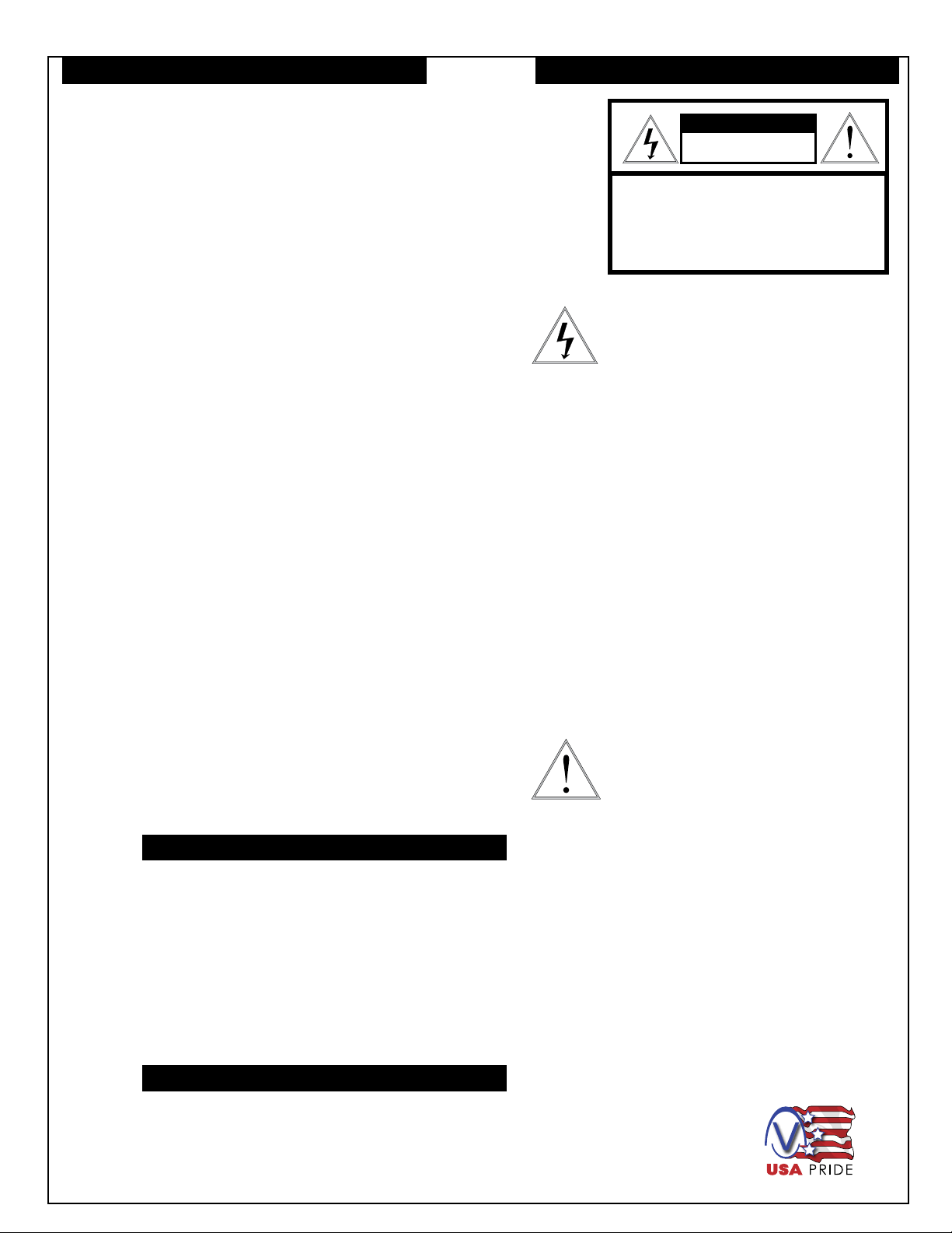
Contents of Box
*** Pan Tilt boxed separately along with its instructions.
Page 5
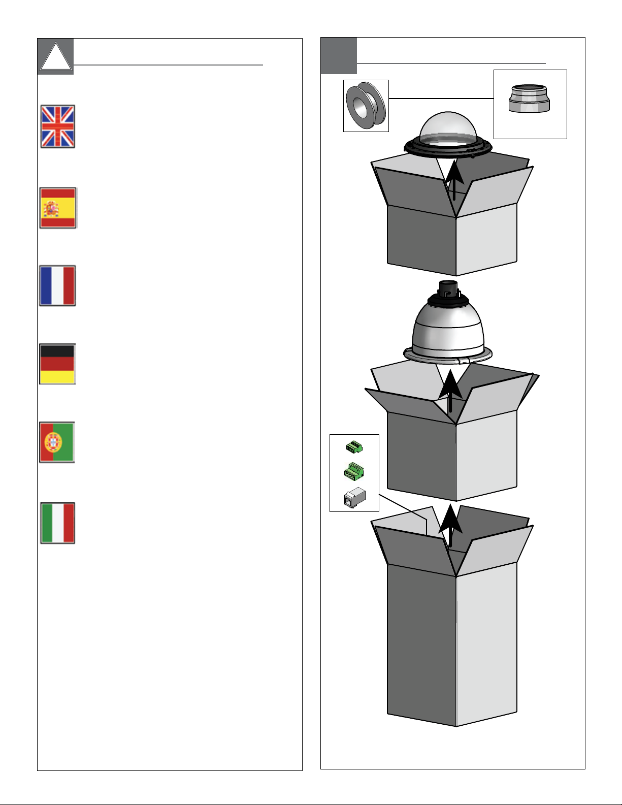
1
Securely mount bracket to wall. Pull wiring
through bracket and position grommet as shown.
• Con seguridad soporte del montaje a emparedar. Tire del cableado
a través del soporte y del ojal de la posición según lo demostrado.
• Solidement parenthèse de bâti à murer. Tirez le câblage par la
parenthèse et le canon isolant de position comme montré.
• Sicher Einfassung Haltewinkel wall. Ziehen Sie Verdrahtung durch
Haltewinkel und Position Gummimuffe, wie gezeigt.
• Firmemente suporte da montagem a wall. Puxe a fiação através do
suporte e do ilhó da posição como mostrado.
• Saldamente staffa del supporto da wall. Tiri i collegamenti tramite la
staffa ed il gommino di protezione di posizione come indicato.
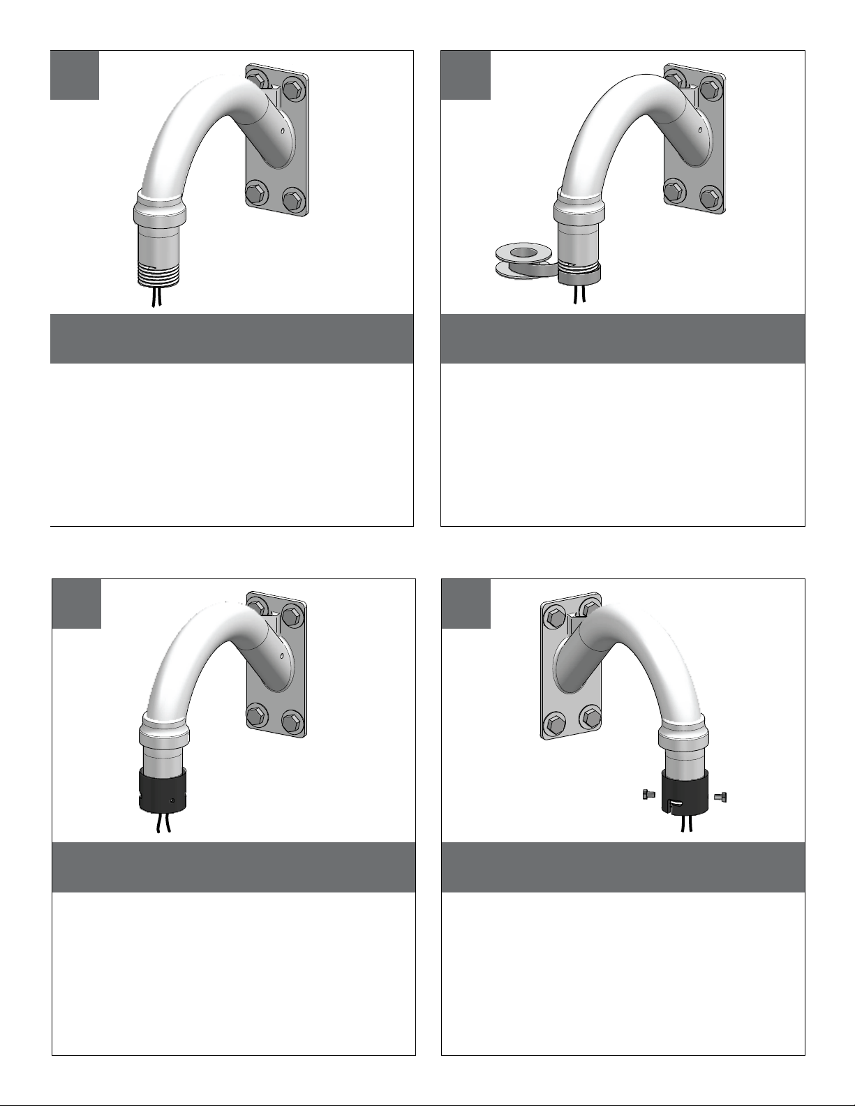
4
Screw the (2) bolts into the coupling.
• Atornille (2) los pernos en el acoplador.
• Vissez (2) les boulons dans l'accouplement.
• Schrauben Sie die (2) Schraubbolzen in die Koppelung.
• Parafuse (2) os parafusos no acoplamento.
• Avviti (2) i bulloni nell'accoppiamento.
2
Wrap Teflon tape around the pipe threads
to ensure a tight seal.
• La cinta del Teflon del abrigo alrededor de la pipa rosca
para asegurar un sello apretado.
• La bande de teflon d'enveloppe autour de la pipe filète
pour assurer un joint serré.
• Verpackung Teflonklebeband um das Rohr verlegt, um
eine feste Dichtung sicherzustellen.
• A fita adesiva do Teflon do envoltório em torno da
tubulação enfía para assegurar um selo apertado.
• Il nastro del Teflon dell'involucro intorno al tubo filetta per
accertare una guarnizione stretta.
TM
3
Screw the coupling onto the pipe threads
until it is hand tight.
• Atornille el acoplador sobre los hilos de rosca de la pipa
hasta que es mano firmemente.
• Vissez le couplage sur les fils de pipe jusqu'à ce que ce
soit main fortement.
• Schrauben Sie die Koppelung auf die Rohrgewinde, bis
es Hand fest ist.
• Parafuse o acoplamento nas linhas da tubulação até
que esteja mão firmemente.
• Avviti l'accoppiamento sui filetti del tubo fino a che non
sia fortemente mano.
SOLD SEPARATELY
SOLD SEPARATELY
SOLD SEPARATELY
SOLD SEPARATELY
Page 6
5
Loop the lanyard over the set screw to
temporarily hold housing.
• Coloque el acollador sobre el tornillo de presión para
celebrar temporalmente la cubierta.
• Faites une boucle la lanière au-dessus de la vis de réglage
pour tenir temporairement le logement.
• Schlingen Sie die Abzuglinie über der Klemmschraube, um
Gehäuse vorübergehend zu halten.
• Dê laços no colhedor sobre o parafuso de fixação para
prender temporariamente a carcaça.
• Colleghi la cordicella in circuito sopra la vite di arresto
temporaneamente per tenere l'alloggiamento.
6
Make the appropriate wiring connections
from the dome to the gooseneck.
• Haga las conexiones apropiadas del cableado de la bóveda
al gooseneck.
• Établissez les rapports appropriés de câblage à partir du dôme
au col de cygne.
• Stellen Sie die passenden Verdrahtung Beziehungen von der
Haube zum gooseneck her.
• Faça as conexões apropriadas da fiação da abóbada ao
gooseneck.
• Faccia i collegamenti adatti dei collegamenti dalla cupola al
gooseneck.
7
Undo the lanyard, pull housing up and twist
secure with the locking bolt and washers.
• Deshaga el acollador, tire de contener para arriba y tuerza seguro
con el perno y las arandelas de fijación.
• Défaites la lanière, tirez loger vers le haut et tordez bloqué avec le
boulon et les rondelles de fermeture.
• Annulieren Sie die Abzuglinie, ziehen Sie oben unterbringen und
verdrehen Sie sicheres mit dem verriegelnschraubbolzen und den
Unterlegscheiben.
• Undo o colhedor, puxe abrigar acima e torça seguro com o
parafuso e as arruelas travando.
• Undo la cordicella, tiri l'alloggio in su e torca sicuro con il bullone e
le rondelle di bloccaggio.
8
Slide the grommet down over the coupling to prevent
water from entering and complete the assembly.
• Resbale el ojal abajo sobre el acoplador para evitar que el agua
entre y para terminar a la asamblea.
• Glissez le canon isolant vers le bas au-dessus de l'accouplement
pour empêcher l'eau d'entrer et pour accomplir l'assemblée.
• Schieben Sie die Gummimuffe unten über der Koppelung, um zu
verhindern, daß Wasser und die Versammlung durchzuführen
hereinkommt.
• Deslize o ilhó para baixo sobre o acoplamento para impedir que a
água entre e para terminar o conjunto.
• Faccia scorrere il gommino di protezione giù sopra l'accoppiamento
per impedire l'acqua entrare e per completare il complessivo.
SOLD SEPARATELY
SOLD SEPARATELY
SOLD SEPARATELY
SOLD SEPARATELY
Page 7
RJ45
RJ45
12VDC
1
2
Camera/Heater/Blower
Camera/Heater/Blower
Yellow
Green
SNC-RZ50/SNC-RZ30
50 Watts
1/0
1
2
Alarm 1
Common
Blue
Violet
A
B
C
D
Wire as shown below for IP
models:(PFD7CN-9; PFD7TN-9)
Make the appropriate male and female connec-
tions. Indoor model does not include pre-run cables.
• Haga las conexiones masculinas y femeninas apropiadas. El
modelo de interior no incluye pre-funciona los cables.
• Établissez les rapports masculins et femelles appropriés. Le
modèle d'intérieur n'inclut pas pré-courent des câbles.
• Stellen Sie die passenden männlichen und weiblichen
Beziehungen her. Innenmodell schließt nicht vor-laufen lassen
Kabel ein.
• Faça as conexões masculinas e fêmeas apropriadas. O
modelo indoor não inclui pre-funciona cabos.
• Faccia i collegamenti maschii e femminili adatti. Il modello
dell'interno non include pre-fa funzionare i cavi.
MM
2
AWG
,5 ,75 1,0 1,5 2,5 4 6
22 20 18 16 14 12 10
The beam angle may be adjusted on the
bottom of the unit.
• Éstos se recomiendan las distancias máximas para
12VDC con una gota del voltage del 10%.
• Ceux-ci sont recommandés des distances maximum
pour 12VDC avec une chute de tension de 10%.
• Diese werden maximale Abstände für 12VDC mit
einem 10% Spannungsabfall empfohlen.
• Estes são recomendados distâncias máximas para
12VDC com uma queda de tensão de 10%.
• Questi sono suggeriti distanze massime per 12VDC
con una differenza de potenziale di 10%.
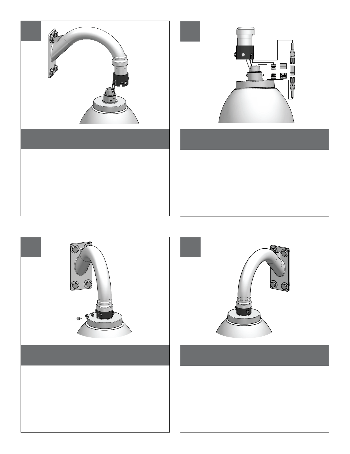
12
These are recommended maximum distances
for 12VDC with a 10% voltage drop.
Remove Pan/Tilt from shipping carton.
Install in base bracket in housing.
• Quite Pan/Tilt del cartón del envío. Instale en soporte
bajo en la cubierta.
• Enlevez Pan/Tilt du carton d'expédition. Installez dans
la parenthèse basse dans le logement.
• Entfernen Sie Pan/Tilt vom Verschiffenkarton. Bringen
Sie in niedrigen Haltewinkel im Gehäuse an.
• Remova Pan/Tilt da caixa do transporte. Instale no
suporte baixo na carcaça.
• Rimuova Pan/Tilt dalla scatola di trasporto. Installi in
staffa bassa in alloggiamento.
A
B
C
D
RJ45
RJ45
12VDC
1
2
Camera/Heater/Blower
Camera/Heater/Blower
Yellow
Green
SNC-RZ50/SNC-RZ30
50 Watts
1/0
1
2
3
4
RS-485RX A
RS-485RX B
RS-485TX A
RS-485TX B
Blue
Violet
Gray
White
Make the appropriate male and female connec-
tions. Indoor model does not include pre-run cables.
• Haga las conexiones masculinas y femeninas apropiadas. El
modelo de interior no incluye pre-funciona los cables.
• Établissez les rapports masculins et femelles appropriés. Le
modèle d'intérieur n'inclut pas pré-courent des câbles.
• Stellen Sie die passenden männlichen und weiblichen
Beziehungen her. Innenmodell schließt nicht vor-laufen lassen
Kabel ein.
• Faça as conexões masculinas e fêmeas apropriadas. O
modelo indoor não inclui pre-funciona cabos.
• Faccia i collegamenti maschii e femminili adatti. Il modello
dell'interno non include pre-fa funzionare i cavi.
Wire as shown below for analog
models: (PFD7CS-9; PFD7TS-9)
9
10
11
12
Page 8
To install the dome align the tabs and twist
counter clockwise to secure.
• Para instalar la bóveda alinee las lengüetas y tuerza al revés
a la derecha para asegurar.
• Pour installer le dôme alignez les étiquettes et tordez contre
dans le sens des aiguilles d'une montre pour fixer.
• Um die Haube anzubringen richten Sie die Vorsprünge aus
und verdrehen Sie sich entgegengesetzt nach rechts um zu
sichern.
• Para instalar a abóbada alinhe as abas e torça-as contra no
sentido horário para fixar-se.
• Per installare la cupola allinei le linguette e torca contro in
senso orario per fissare.
Hand tighten the screws on the dome.
Recommended torque 12 inches/lb (1.35Nm).
• La mano aprieta los tornillos en la bóveda. Esfuerzo de
torsión recomendado 12 inches/lb (el 1.35Nm).
• La main serrent les vis sur le dôme. Couple recommandé 12 inches/lb (1.35Nm).
• Hand ziehen die Schrauben an der Haube fest.
Empfohlene Drehkraft 12 inches/lb (1.35Nm).
• A mão aperta os parafusos na abóbada. Torque
recomendado 12 inches/lb (1.35Nm).
• La mano stringe le viti sulla cupola. Coppia di torsione
suggerita 12 inches/lb (1.35Nm).
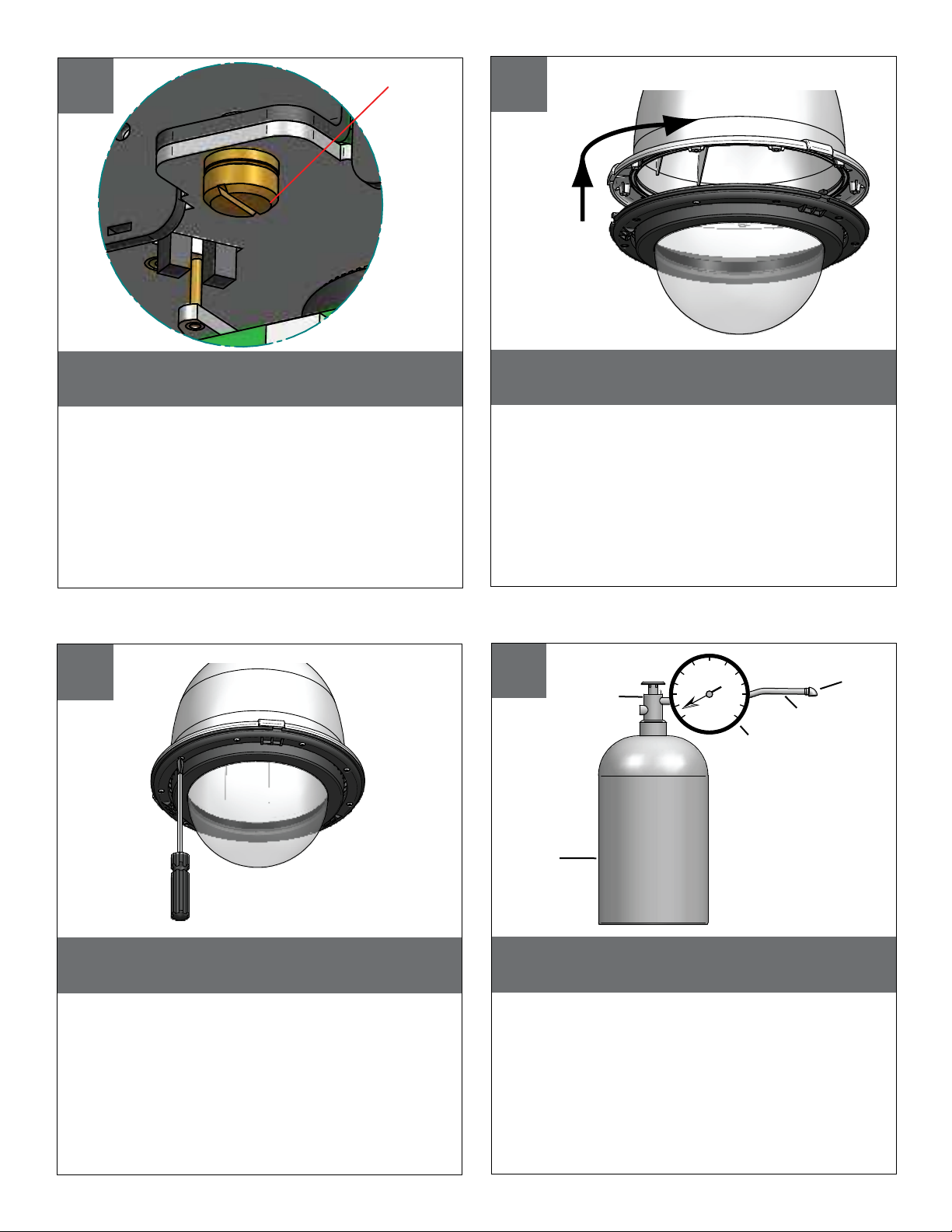
When pressurizing unit be sure to set the
guage or regulator from 10-20psi (.7-1.4bar).
• Al presurizar la unidad sea seguro fijar la medida o el
regulador de 10-20psi (7-1.4bar).
• En pressurisant l'unité soyez sûr de placer la jauge ou le
régulateur de 10-20psi (7-1.4bar).
• Wenn Sie Maßeinheit unter Druck setzen, seien Sie sicher,
das Eichmaß oder den Regler von 10-20psi (7-1.4bar)
einzustellen.
• Ao pressurizar a unidade seja certo ajustar o guage ou o
regulador de 10-20psi (7-1.4bar).
• Nel pressurizzare l'unità sia sicuro regolare il misuratore o
il regolatore da 10-20psi (7-1.4bar).
PSI
0
50
100
150
200
250
300
Nitrogen
Tank
Hose
Regulator
Air Chuck
580
Fitting
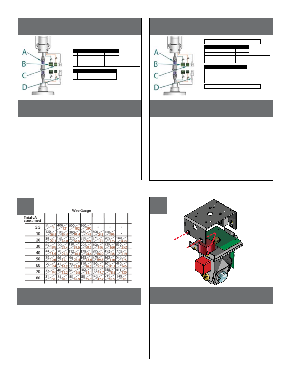
CAPTIVE SCREW
To secure in place, tighten captive screw.
• Para asegurar en lugar, apriete el tornillo prisionero.
• Pour fixer en place, serrez la vis captive.
• Um im Platz zu sichern, ziehen Sie Sicherheitsschraube
fest.
• Para fixar-se no lugar, aperte o parafuso prisioneiro.
• Per fissare sul posto, stringa la vite prigioniera.
13
14
15
16
Page 9

Place the air chuck on the tank valve and
begin filling until pressure relief valve opens.
• Coloque la tirada del aire en la válvula del tanque y comience
a llenar hasta que la válvula de descarga de presión se abre.
• Placez le mandrin d'air sur la valve de réservoir et commencez
à remplir jusqu'à ce que la valve de décompression s'ouvre.
• Setzen Sie die Luftklemme auf das Behälterventil und fangen Sie
an zu füllen, bis Druckablaßventil sich öffnet.
• Coloque o mandril do ar na válvula do tanque e comece a
encher-se até que a válvula de escape de pressão abra.
• Disponga il mandrino dell'aria sulla valvola del carro armato e
cominci a riempirsi fino a che la valvola limitatrice della
pressione non si apra.
Air Chuck
Tank
Valve
Open the relief valve. Drain all air from the housing and
repeat twice to remove all moisture.
• Abra la válvula de descarga. Drene todo el aire de la cubierta y
de la repetición dos veces para quitar toda la humedad.
• Ouvrez la soupape de sécurité. Évacuez tout l'air le logement et la
répétition deux fois pour enlever toute l'humidité.
• Öffnen Sie das Sicherheitsventil. Lassen Sie alle Luft aus dem
Gehäuse und der Wiederholung zweimal ab, um alle Feuchtigkeit
zu entfernen.
• Abra a válvula de escape. Drene todo o ar da carcaça e do
repeat duas vezes para remover toda a umidade.
• Apra la valvola di sfiato. Vuoti due volte tutta l'aria
dall'alloggiamento e dalla ripetizione per rimuovere tutta l'umidità.
The beam angle may be adjusted on the
bottom of the unit.
• Energía encima de la unidad.
• Puissance vers le haut de l'unité.
• Energie herauf die Maßeinheit.
• Poder acima da unidade.
• Alimentazione sull'unità.
12
Power up the unit.
After purging check the housing pressure. It
should be around 5psi (.34bar).
• Después de purgar el cheque la presión de la cubierta.
Debe estar alrededor de 5psi (34bar).
• Après la purge du contrôle la pression de logement. Elle
devrait être autour de 5psi (34bar).
• Nachdem Überprüfung der Gehäusedruck bereinigt
worden ist. Sie sollte um 5psi (34bar) sein.
• Após ter removido a verificação a pressão da carcaça.
Deve ser em torno de 5psi (34bar).
• Dopo l'eliminazione dell'inceppo del controllo la pressione
dell'alloggiamento. Dovrebbe essere intorno a 5psi
(34bar).
PSI
0
5
10
15
20
25
30
17
18
19
20
Page 10

PFD7C12N-9
Replacement Parts List
4
3
2
1
1
5
7
6
12
11
8
10
9
16
14
15
17
13
Part No. Description
1 RPPFDT02 Housing Top (Extended)
2 RPVL1938 Removable Pendent Coupling
3 RPVL1802 Plastic Rain Shroud
4 RPVL1795 Tank Valve Gasket
5 RP96RSORG11 Main O-Ring 9.25"
6 RPPFDTR01 Trim Ring w/o Dome
7 RCPFD7 Clear Dome with sealing O-Ring
7b RCTPFD7 Tinted Dome with sealing O-Ring
8 RPPFDT03 Internal Sealing Bracket Assembly
9 RP96RSORG10 Small O-Ring 4.5"
10 RP70PT07a Hermetic Connector, Gasket, Cable
11 RP95VALV08 5 to 7 psi Pressure Relief Valve
12 RP95VALV07 Tank Valve
13 RPFD072112 24VAC Heater
14 RP46PKH3063 Spacers Packet
15 RP40PCMOD01 Connection PCB
16 RPFD060 Main Bracket Assembly
17 RPFD080 Blower
N/S RP40CAPPFD811 External Input Video/Power Cables
N/S RP46PKH2200 Packet Assembly-Hardware
N/S RP46PKE1100 Packet Assembly-Electrical
19
20
18
21
23
22
18 RPVL2857 P/T Base Bracket
19 RP76v385A P/T Connection Card
(Network Models Only)
20 RPVL3097 IP Card Bracket
21 RP70p14015 IP Card
22 RP96PSGK08 P/T Grommet (2)
23 RP76P0F060E IP Connection Card
(Network Models Only)
(Network Models Only)
N/S WM20G GOOSE NECK (SOLD SEPARATELY
)
Page 11

-
www.videolarm.com
S - V I E W PAN / T I LT
Analog & IP
Installation and Operation Supplement:
Before attempting to connect or operate this product,
please read these instructions completely.
81-IN5409
01-29-2009
Page 12

S-VIEW PAN/ TILT
S-view: Analog 13 WATTS
S-view: IP 28 WATTS
MODELS: 12VDC
S-view: Analog 13 WATTS
S-view: IP 20 WATTS
Fuente De Alimentación De la Clase 2 Solamente.
MODELOS: 24 VAC
S-vista: Análogo 13 VATIOS
S-vista: IP 28 VATIOS
MODELOS: 12VDC
S-vista: Análogo 13 VATIOS
S-vista: IP 20 VATIOS.
Alimentation D'Énergie De la Classe 2 Seulement
MODÈLES : 24 VCA
S-vue : Analogue 13 WATTS
S-vue : IP 28 WATTS
MODÈLES : 12VDC
S-vue : Analogue 13 WATTS
S-vue : IP 20 WATTS.
Nur Kategorie 2 Spg. Versorgungsteil
MODELLE: 24 VAC
S-Ansicht: Analog 13 WATT
S-Ansicht: IP 28 WATT
MODELLE: 12VDC
S-Ansicht: Analog 13 WATT
S-Ansicht: IP 20 WATT.
Fonte De Alimentação Da Classe 2 Somente
MODELOS: 24 VAC
S-vista: Análogo 13 WATTS
S-vista: IP 28 WATTS
MODELOS: 12VDC
S-vista: Análogo 13 WATTS
S-vista: IP 20 WATTS
Gruppo di alimentazione Del Codice categoria 2 Soltanto
MODELLI: 24 VCA
S-vista: Analog 13 WATT
S-vista: IP 28 WATT
MODELLI: 12VDC
S-vista: Analog 13 WATT
S-vista: IP 20 WATT.
Electrical Specifications
Class 2 Power Supply Only
MODELS: 24 VAC
!!
Français
Deutsch
Italiano
Portuguese
Español
English
Content of Box
Page 13

Remove Pan/Tilt from shipping carton.
Install in base bracket in housing.
• Quite Pan/Tilt del cartón del envío. Instale en soporte
bajo en la cubierta.
• Enlevez Pan/Tilt du carton d'expédition. Installez dans
la parenthèse basse dans le logement.
• Entfernen Sie Pan/Tilt vom Verschiffenkarton. Bringen
Sie in niedrigen Haltewinkel im Gehäuse an.
• Remova Pan/Tilt da caixa do transporte. Instale no
suporte baixo na carcaça.
• Rimuova Pan/Tilt dalla scatola di trasporto. Installi in
staffa bassa in alloggiamento.
CAPTIVE SCREW
To secure in place, tighten captive screw.
• Para asegurar en lugar, apriete el tornillo prisionero.
• Pour fixer en place, serrez la vis captive.
• Um im Platz zu sichern, ziehen Sie Sicherheitsschraube
fest.
• Para fixar-se no lugar, aperte o parafuso prisioneiro.
• Per fissare sul posto, stringa la vite prigioniera.
To set camera address locate PC board on
the side of Pan/Tilt unit. (Analog)
• Para fijar la dirección de la cámara fotográfica localice
el tablero de PC en el lado de la unidad de Pan/Tilt.
• Pour placer l'adresse d'appareil-photo localisez le
panneau de PC du côté de l'unité de Pan/Tilt.
• Um Kameraadresse einzustellen lokalisieren Sie PC Brett
auf der Seite der Pan/Tilt Maßeinheit.
• Para ajustar o endereço da câmera encontre a placa
de PC no lado da unidade de Pan/Tilt.
• Per regolare l'indirizzo della macchina fotografica
individui il bordo del pc dal lato dell'unità di Pan/Tilt.
PC Board
located here
Use the 8 position Dip switch to set address
lower corner. (Analog)
• Utilice el interruptor dip de 8 posiciones para fijar una
esquina más baja de la dirección.
• Utilisez le contact DIP de 8 positions pour placer le
coin inférieur d'adresse.
• Benutzen Sie den 8 Position DIP-Schalter, um Adresse
unterere Ecke einzustellen.
• Use o interruptor de mergulho de 8 posições ajustar
um canto mais baixo do endereço.
• Utilizzi l'interruttore di tuffo di 8 posizioni per regolare il
angolo più basso di indirizzo.
?
Address Dip
Switches
Factory Settings
DO NOT ADJUST
1
2
43
Page 14

OFF
ON
To set the address at “0” side the all switches off
as shown. See table in back for address 0-255
• Para fijar la dirección en "0" lados todos los interruptores
apagado según lo demostrado. Vea la tabla adentro detrás
para la dirección 0-255
• Pour placer l'adresse sur "0" côtés les tous les commutateurs
au loin comme montré. Voir le tableau dedans en arrière
pour l'adresse 0-255
• Die Adresse an "0" Seite weg einstellen die alle Schalter, wie
gezeigt. Sehen Sie Tabelle innen zurück für Adresse 0-255
• Para ajustar fora o endereço em "0" lados todos os interruptores como mostrado. Veja a tabela dentro para trás para o
endereço 0-255
• Per regolare l'indirizzo "su 0" lati tutti gli interruttori fuori come
indicato. Veda la tabella dentro indietro per l'indirizzo 0-255
(Analog)
PROTOCOLS
The S-View Pan/Tilt support the above protocols.
This is done automatically no settings are
required.
• La ayuda de la S-Vista Pan/Tilt los protocolos antedichos. Se
requiere esto se hace automáticamente ningunos ajustes.
• L'appui de la S-Vue Pan/Tilt les protocoles ci-dessus. Ceci est
fait automatiquement aucuns arrangements sont exigés.
• Die S-Ansicht Pan/Tilt Unterstützung die oben genannten
Protokolle. Diesem wird automatisch keine Einstellungen
werden angefordert getan.
• A sustentação da S-Vista Pan/Tilt os protocolos acima. Isto é
feito automaticamente nenhuns ajustes é requerido.
• Il supporto di S-Vista Pan/Tilt i suddetti protocolli. Ciò è fatta
automaticamente nessun regolazioni è richiesta.
1 VL422
2 PELCO P 4800/9600
3 PELCO D 4800/9600
When using Videolarm controller; to enter the
menu; select the camera you wish to control.
• Al usar el regulador de Videolarm; para incorporar el menú;
seleccione la cámara fotográfica que usted desea controlar.
• En utilisant le contrôleur de Videolarm ; pour écrire le menu ;
choisissez l'appareil-photo que vous souhaitez commander.
• Wenn Videolarm Steuerpult verwendet wird; das Menü
eintragen; wählen Sie die Kamera vor, die Sie steuern
möchten.
• Ao usar o controlador de Videolarm; para incorporar o
menu; selecione a câmera que você deseja controlar.
• Nel usando il regolatore di Videolarm; per entrare nel menu;
selezioni la macchina fotografica che desiderate controllare.
1
2
3
4
5
6
7 8
9
0
*
#
1, 2, 3...
F
Camera
MENU DRIVEN SETTINGS (Analog)
Then press 95 followed by the Preset
button ( ).
• Entonces la prensa 95 siguió por preestableció el
botón ( ).
• Alors la pression 95 a suivi de a préréglé le bouton
( ).
• Dann folgte Presse 95 von einstellte Taste ( ).
• Então a imprensa 95 seguiu pelo pré-ajustou a
tecla ( ).
• Allora la pressa 95 è seguito dal ha prestabilito il
tasto ( ).
1
2
3
4
5
6
7 8
9
0
*
#
1, 2, 3...
F
MENU DRIVEN SETTINGS (Analog)
Presets
5
6
7
8
Page 15

IP INSTRUCTIONS: The factory default IP
address is : 192.168.0.200.
• INSTRUCCIONES DEL IP: El IP address del defecto de la
fábrica es: 192.168.0.200.
• INSTRUCTIONS D'IP : Le IP address de défaut d'usine est :
192.168.0.200.
• IP ANWEISUNGEN: Das Fabrikrückstellung IP address ist:
192.168.0.200.
• INSTRUÇÕES DO IP: O IP address do defeito da fábrica
é: 192.168.0.200.
• ISTRUZIONI DEL IP: Il IP address di difetto della fabbrica
è: 192.168.0.200.
Control interface for IP PTZ control.
• Controle el interfaz para el control del IP PTZ.
• Commandez l'interface pour la commande d'IP PTZ.
• Steuern Sie Schnittstelle IP PTZ zur Steuerung.
• Controle a relação para o controle do IP PTZ.
• Controlli l'interfaccia per controllo del IP PTZ.
Select
PreSets
Lens
Functions
Pan/Tilt
functions
(also used
to scroll
camera
menu)
Use to
save or
remove
PreSets
For Pan Tilt control click on the PTZ control
icon in top right corner.
• Para el control de la inclinación de la cacerola chasque
encendido el icono del control de PTZ en esquina derecha
superior.
• Pour le clic de commande d'inclinaison de casserole sur
l'icône de commande de PTZ dans le bon coin supérieur.
• Zur Wanne Neigungsteuerung klicken Sie an die PTZ
Steuerikone in der Rechteecke.
• Para o controle da inclinação da bandeja estale sobre o
ícone do controle de PTZ no canto direito superior.
• Per controllo di ribaltamento della vaschetta scatti sopra
l'icona di controllo di PTZ nel giusto angolo superiore.
See IP Camera instruction CD for operation
details.
• Vea el CD de la instrucción de la cámara fotográfica
del IP para los detalles de la operación.
• Voir le CD d'instruction d'appareil-photo d'IP pour des
détails d'opération.
• Sehen Sie IP Kamera-Anweisung CD für Betrieb Details.
• Veja o CD da instrução da câmera do IP para detalhes da operação.
• Veda il CD di istruzione della macchina fotografica del
IP per i particolari di funzionamento.
9
10
(IP)
(IP)
(IP)
1211
(IP)
Page 16

DISPLAY / MENU
Use Up & Down control on the controller to
navigate through the menu. Pan left and right are
used to enter sub menus.
• Utilice para arriba y abajo controle en el regulador para navegar a través
del menú. La cacerola a la izquierda e a la derecha se utiliza para
incorporar menús secundarios.
• Épuisez et commandez vers le bas sur le contrôleur pour diriger par le menu.
La casserole à gauche et à droite sont utilisées pour écrire les menus
secondaires.
• Verwenden Sie oben u. steuern Sie unten auf dem Steuerpult, um durch das
Menü zu steuern. Verschieben Sie links und recht werden verwendet,
Vormenüs einzutragen.
• Use acima & controle para baixo no controlador para navigate através do
menu. Garimpe esquerdo e direito são usados incorporar menus
secundários.
• Consumi & giù controlli sul regolatore per traversare attraverso il menu. La
vaschetta a destra e a sinistra è utilizzata per entrare nei menu secondari..
DISPLAY / COMPASS
Use this submenu to activate compass heading. Press
zoom in to turn on, zoom out to turn off, Pan Left to exit.
• Utilice este submenu para activar el título de compás. Presione el zumbido
adentro para girarse, zumbido hacia fuera a dan vuelta apagado,
cacerola izquierda a la salida.
• Employez ce submenu pour activer le titre de boussole. Serrez le
bourdonnement dedans pour se tourner dessus, bourdonnement dehors
vers se tournent au loin, casserole gauche vers la sortie.
• Verwenden Sie dieses submenu, um Kompaßsteuerkurs zu aktivieren.
Betätigen Sie Zoom innen, um, Zoom heraus an an zu wenden wenden
weg, die Wanne, die an Ausgang link ist.
• Use este submenu ativar o título de compasso. Pressione o zumbido dentro
para girar sobre, zumbido para fora para desligam, bandeja esquerda
para a saída.
• Usi questo submenu per attivare l'intestazione di bussola. Premi lo zoom
dentro per girarsi sopra, zoom fuori verso si girano fuori, vaschetta di sinistra
verso l'uscita.
DISPLAY / SET NORTH
Use the “Zoom In” botton to set calibration.
Display will show OK.
• Utilice el "zumbido en" botton para fijar la calibración. La exhibición
demostrará MUY BIEN.
• Employez l'"bourdonnement dans" le botton pour placer le calibrage.
L'affichage montrera BIEN.
• Benutzen Sie den "Zoom" im botton, um Kalibrierung einzustellen.
Anzeige stellt O.K. dar.
• Use o "zumbido" no botton ajustar a calibração. A exposição mostrará
ESTÁ BEM.
• Usi "lo zoom" nel botton per regolare la calibratura. L'esposizione
mostrerà BENE.
DISPLAY / POSITION
A numeric camera position is shown on
monitor. With “Position” activated.
• Una posición numérica de la cámara fotográfica se
demuestra respecto a monitor. Con la "Posición" activó.
• Une position numérique d'appareil-photo est montrée
sur le moniteur. Avec l'"Position" a activé.
• Eine numerische Kameraposition wird auf Monitor
gezeigt. Wenn "Position" aktiviert ist.
• Uma posição numérica da câmera é mostrada no
monitor. Com "Posição" ativou.
• Una posizione numerica della macchina fotografica è
indicata sul video. Con "Posizione" ha attivato.
13
14
1615
Page 17

DISPLAY / ADDRESS
When activated this will display camera’s
address on the monitor.
• Cuando está activado esto exhibirá la dirección de la
cámara fotográfica en el monitor.
• Quand activé ceci montrera l'adresse de l'appareilphoto sur le moniteur.
• Wenn Sie diesem aktiviert werden, zeigt Adresse der
Kamera auf dem Monitor an.
• Quando ativado isto indicará o endereço da câmera
no monitor.
• Una volta attivato questo visualizzerà l'indirizzo della
macchina fotografica sul video.
DISPLAY / TEMP.
Will display temperature data from Pan/Tilt on
monitor.
• Exhibirá datos de la temperatura de Pan/Tilt en
monitor.
• Montrera des données de la température de Pan/Tilt
sur le moniteur.
• Zeigt Temperaturdaten von Pan/Tilt auf Monitor an.
• Indicará dados da temperatura de Pan/Tilt no monitor.
• Visualizzerà i dati di temperatura da Pan/Tilt sul video.
DISPLAY / PRESSURE
Will display pressure data from Pan/Tilt on
monitor. This feature is only available on
select models.
• Exhibirá datos de la presión de Pan/Tilt en monitor. Esta
característica está solamente disponible en modelos
selectos.
• Montrera des données de pression de Pan/Tilt sur le
moniteur. Ce dispositif est seulement disponible sur les
modèles choisis.
• Zeigt Druckdaten von Pan/Tilt auf Monitor an. Diese
Eigenschaft ist auf auserwählten Modellen nur vorhanden.
• Indicará dados da pressão de Pan/Tilt no monitor. Esta
característica está somente disponível em modelos
seletos.
• Visualizzerà i dati di pressione da Pan/Tilt sul video. Questa
caratteristica è soltanto disponibile sui modelli prescelti.
CAMERA / MENU
Use camera menu to activate selected
camera features.
• Utilice el menú de la cámara fotográfica para activar
características seleccionadas de la cámara fotográfica.
• Employez le menu d'appareil-photo pour activer les
dispositifs choisis d'appareil-photo.
• Benutzen Sie Kameramenü, um vorgewählte Kameraeigenschaften zu aktivieren.
• Use o menu da câmera ativar características selecionadas da câmera.
• Usi il menu della macchina fotografica per attivare le
caratteristiche selezionate della macchina fotografica.
17
18
19
20
Page 18

CAMERA / STABILIZATION
Camera sub menu includes, image
stabilization, day/night mode, shutter,
backlight, AGC and digital zoom. Image
stabilization is not a feature of all cameras.
• El menú secundario de la cámara fotográfica incluye, estabilización de la
imagen, modo de day/night, obturador, contraluz, AGC y zumbido digital.
La estabilización de la imagen no es una característica de todas las
cámaras fotográficas.
• Le menu secondaire d'appareil-photo inclut, stabilisation d'image, mode de
day/night, obturateur, contre-jour, AGC et bourdonnement numérique. La
stabilisation d'image n'est pas un dispositif de tous les appareils-photo.
• Kameravormenü schließt, Bildausgleichung, day/night Modus, Blendenverschluß, Hintergrundbeleuchtung, AGC und digitaler Zoom ein. Bildausgleichung ist nicht eine Eigenschaft aller Kameras.
• O menu secundário da câmera inclui, estabilização da imagem, modalidade de day/night, obturador, luminoso, AGC e zumbido digital. A
estabilização da imagem não é uma característica de todas as câmeras.
• Il menu secondario della macchina fotografica include, stabilizzazione di
immagine, modo di day/night, otturatore, lampadina, AGC e zoom digitale.
La stabilizzazione di immagine non è una caratteristica di tutte le macchine
fotografiche.
ALARM / MENU
Use sub menu to activate alarm. When
enabled camera will go to preset “1” when
alarm input is closed.
• Utilice el menú secundario para activar el alarmar. Cuando está
permitida la cámara fotográfica irá a preestablecer "1" cuando la
entrada del alarmar es cerrada.
• Employez le menu secondaire pour activer l'alarme. Quand permis
l'appareil-photo ira prérégler "1" quand l'entrée d'alarme est
fermée.
• Benutzen Sie Vormenü, um Warnung zu aktivieren. Wenn sie
ermöglicht wird, geht Kamera, "1" einzustellen, wenn Warnung
Eingang geschlossen ist.
• Use o menu secundário ativar o alarme. Quando permitida a
câmera irá pré-ajustar "1" quando a entrada do alarme é closed.
• Usi il menu secondario per attivare l'allarme. Una volta permessa la
macchina fotografica andrà prestabilire "1" quando l'input
dell'allarme è chiuso.
ZONE / SHOW
Will show title of the zone on monitor when
activated.
• Demostrará el título de la zona en monitor cuando está activado.
• Montrera le titre de la zone sur le moniteur quand activé.
• Zeigt Titel der Zone auf Monitor, wenn Sie aktiviert werden.
• Mostrará o título da zona no monitor quando ativado.
• Mostrerà il titolo della zona sul video una volta attivato.
ZONE / PRIV.
Turn on “PRIV” to activate; Rlimit will turn off
menu, to allow you to position right limit for
zone.
• Gire "PRIV" para activar; el rlimit dará vuelta apagado al menú,
para permitir que usted coloque el límite derecho para la zona.
• Allumez "PRIV" pour activer ; le rlimit arrêtera le menu, pour vous
permettre de placer la bonne limite pour la zone.
• Schalten Sie "PRIV" ein, um zu aktivieren; rlimit stellt Menü ab, um
Ihnen zu erlauben, rechte Begrenzung für Zone in Position zu
bringen.
• Gire sobre "PRIV" para ativar; o rlimit desligará o menu, para
permitir que você posicione o limite direito para a zona.
• Accenda "PRIV" per attivare; il rlimit spegnerà il menu, per
permettere che posizioniate il giusto limite per la zona.
21
22
2423
Page 19

ZONE / LLIMIT
Llimit will “turn off” menu and allow you to
position camera for left limit of zone.
• Voluntad de Llimit "dar vuelta apagado" al menú y permitir que
usted coloque la cámara fotográfica para el límite izquierdo de la
zona.
• Volonté de Llimit "arrêter" le menu et vous permettre de placer
l'appareil-photo pour la limite gauche de la zone.
• Llimit Wille Menü "" abstellen und Ihnen erlauben, Kamera für linke
Begrenzung auf Zone in Position zu bringen.
• Vontade de Llimit "para desligar" o menu e para permitir que você
posicione a câmera para o limite esquerdo da zona.
• Volontà di Llimit "spegnere" menu e permettere che posizioniate
macchina fotografica per il limite di sinistra della zona.
ZONE / TITLE
Shows on menu screen title characters
selected.
• Demostraciones en los caracteres del título de la pantalla de
menú seleccionados.
• Expositions sur des caractères de titre d'écran menu choisis.
• Erscheinen auf den Menüschirm-Titelbuchstaben vorgewählt.
• As mostras em caráteres do título da tela de menu selecionaram.
• Le esposizioni sui caratteri di titolo dello schermo di menu hanno
selezionato.
ZONE / SET TITLE
Allow you to select title characters. Pan left or right to
change character position. Use tilt up/down to show
characters. Press zoom in to set title-exit menu zoom
out will restore to original title.
• Permita que usted seleccione caracteres del título. Filtre izquierdo o derecho
cambiar la posición de carácter. Utilice la inclinación up/down para demostrar
caracteres. El zumbido de la prensa adentro para fijar el zumbido del menú de la
ti'tulo-salida hacia fuera restaurará al título original.
• Permettez-vous de choisir des caractères de titre. Filtrez gauche ou droit de
changer la position d'impression. Employez l'inclinaison haut/bas pour montrer des
caractères. Le bourdonnement de pression dedans pour placer le bourdonnement
de menu de titre-sortie dehors reconstituera au titre original.
• Erlauben Sie Ihnen, Titelbuchstaben vorzuwählen. Verschieben Sie links oder recht,
Zeichenstelle zu ändern. Verwenden Sie die Neigung, die, um Buchstaben zu zeigen
Auf-/Ab ist. Der Presse Zoom innen, zum von von Titel-Ausgang Menü Zoom heraus
einzustellen stellt zum ursprünglichen Titel wieder her.
• Permita que você selecione caráteres do título. Garimpe esquerdo ou direito para
mudar a posição de caráter. Use a inclinação up/down mostrar caráteres. O
zumbido da imprensa dentro para ajustar o zumbido do menu da título-saída para
fora restaurará ao título original.
• Permetta che selezioniate i caratteri di titolo. Filtri di sinistra o di destra per cambiare
la posizione del carattere. Usi l'inclinazione up/down per mostrare i caratteri. Lo
zoom della pressa dentro per regolare lo zoom del menu dell'titolo-uscita fuori
ristabilirà al titolo originale.
SYSTEM INFO
Displays Pan version, Tilt version, current Pan
position, and current Tilt position.
• Versión de la cacerola de las exhibiciones, versión de la
inclinación, posición actual de la cacerola, y posición actual de
la inclinación.
• Version de casserole d'affichages, version d'inclinaison, position
actuelle de casserole, et position actuelle d'inclinaison.
• Anzeigen Wanne Version, Neigungversion, gegenwärtige Wanne
Position und gegenwärtige Neigungposition.
• Versão da bandeja das exposições, versão da inclinação,
posição atual da bandeja, e posição atual da inclinação.
• Versione della vaschetta delle esposizioni, versione di
inclinazione, attuale posizione della vaschetta ed attuale
posizione di inclinazione.
25
26
2827
Page 20

PRESETS
Allow user to set dwell time for each stored preset. If
presets have not been saved the dwell time for that
preset will be displayed as “”.
• Permita que el usuario fije el tiempo de detención para cada uno
almacenada preestablecen. Si las precolocaciones no se han
ahorrado la época de detención para ese preestablezca será
exhibido como "".
• Permettez à l'utilisateur de placer le temps d'angle de saturation pour
chacun stocké prérèglent. Si des préréglages que le démuni économisé le moment d'angle de saturation pour le ce a préréglés seront
montrés comme "".
• Erlauben Sie Benutzer, Verweilzeit für gespeichertes jedes einzustellen
einstellen. Wenn Voreinstellungen nicht die Verweilzeit für dieses
gespeichert worden sind, stellen Sie wird angezeigt wie "" ein.
• Permita que o usuário ajuste o tempo de interrupção para cada um
armazenado pré-ajustam. Se os pré-ajustes não forem conservados o
momento de interrupção para o esse pré-ajuste estará indicado como
"".
• Permetta che l'utente regoli il tempo di abitazione per ciascuno
immagazzinato prestabiliscono. Se i preregolamenti non sono stati
conservati il momento di abitazione per il quel prestabilisca sarà
visualizzato come "".
PRESETS
Allows user to set dwell time for each existing stored
preset. The above screen show (6) stored presets, with
dwell times of, 9,5,12,5,5,5 seconds.
• Permite que el usuario fije el tiempo de detención para que cada uno
el existir almacenado preestableció. Las precolocaciones almacenadas (6) antedicho de la demostración de la pantalla, con tiempos de
detención de, 9.5.12.5.5.5 segundos.
• Permet à l'utilisateur de placer le temps d'angle de saturation pour que
chacun exister stocké a préréglé. Les préréglages stockés par (6)
ci-dessus d'exposition d'écran, avec des temps d'angle de saturation
de, 9.5.12.5.5.5 secondes.
• Erlaubt Benutzer, Verweilzeit für jedes einzustellen, stellte das Bestehen
gespeichert ein. Die oben genanntes gespeicherten Voreinstellungen
des Schirmerscheinens (6), mit Verweilzeiten von, 9.5.12.5.5.5 Sekunden.
• Permite que o usuário ajuste o tempo de interrupção para que cada
um existir armazenado pré-ajustou. Os pré-ajustes armazenados da
mostra da tela (6) acima, com tempos de interrupção de, 9.5.12.5.5.5
segundos.
• Permette che l'utente regoli il tempo di abitazione per ciascuno esistere
memorizzato ha prestabilito. Suddetto i preregolamenti che
immagazzinati di esposizione dello schermo (6), con i tempi di
abitazione di, 9.5.12.5.5.5 secondi.
EXIT
Select exit to leave menu options.
• Seleccione la salida para dejar opciones del
menú.
• Choisissez la sortie pour laisser des options de
menu.
• Wählen Sie Ausgang vor, um Menüwahlen zu
lassen.
• Selecione a saída para deixar opções do menu.
29
To activate a Tour of Preset press Auto Tour
Button( ) on controller after exiting menu.
• Para activar un viaje de preestablezca el viaje auto Button
( ) de la prensa en regulador después de salir del menú.
• Pour activer une excursion de préréglez l'excursion automatique Button( ) on d'excursion de pression après avoir sorti le
menu.
• Um eine Tour von zu aktivieren stellen Sie Presse Selbsttour
Button( ) on Steuerpult ein nachdem Sie Menü herausgenommen haben.
• Para ativar uma excursão de pré-ajuste a auto excursão
Button( ) on da excursão da imprensa o auto após ter
retirado o menu.
• Per attivare un giro di prestabilisca il giro auto Button( ) on
di giro della pressa dopo avere rimosso il menu.
1
2
3
4
5
6
7 8
9
0
*
#
1, 2, 3...
F
MENU DRIVEN SETTINGS
AUTO
TOUR
30
31
19
32
Page 21

To set a manually controlled pattern by
joystick set Preset 80 (80,#, ).
• Para fijar un patrón manualmente controlado por el sistema
de la palanca de mando preestablezca 80 (80, #, ).
• Pour placer un modèle manuellement commandé par
l'ensemble de manche préréglez 80 (80, #, ).
• Um ein manuell gesteuertes Muster durch Steuerknüppelsatz
einzustellen stellen Sie 80 ein (80, #, ).
• Para ajustar um teste padrão manualmente controlado
pelo jogo do manche pré-ajuste 80 (80, #, ).
• Per determinare un modello manualmente controllato
dall'insieme della barra di comando prestabilisca 80 (80, #,
).
1
2
3
4
5
6
7 8
9
0
*
#
1, 2, 3...
F
Using the joystick move Pan/Tilt to desired
positions where you can record up to 128
seconds of movement.
• Con la palanca de mando mueva Pan/Tilt a las posiciones deseadas
donde usted puede registrar hasta 128 segundos de movimiento.
• En utilisant le manche déplacez Pan/Tilt aux positions désirées où vous
pouvez enregistrer jusqu'à 128 secondes de mouvement.
• Mit dem Steuerknüppel verschieben Sie Pan/Tilt auf gewünschte
Positionen, in denen Sie bis 128 Sekunden Bewegung notieren können.
• Usando o manche mova Pan/Tilt para as posições desejadas onde
você pode gravar até 128 segundos do movimento.
• Per mezzo della barra di comando sposti Pan/Tilt verso le posizioni
volute dove potete registrare fino a 128 secondi di movimento.
Press Preset 81 to stop recording (81,#, ).
Preset 80, to start pattern.
• Presione preestablecen 81 para parar el registrar (81, #, ).
Preestablezca 80, para comenzar el patrón.
• Serrez prérèglent 81 pour cesser d'enregistrer (81, #, ).
Préréglez 80, pour commencer le modèle.
• Betätigen Sie sich einstellen 81, um zu notieren zu stoppen
(81, #, ). Stellen Sie 80 ein, um Muster zu beginnen.
• Pressione pré-ajustam 81 para parar de gravar (81, #, ).
Pré-ajuste 80, para começar o teste padrão.
• Premi prestabiliscono 81 per smettere di registrare (81, #, ).
Prestabilisca 80, per iniziare il modello.
1
2
3
4
5
6
7 8
9
0
*
#
1, 2, 3...
F
Presets
OTHER FEATURES:
Home Preset
Preset 1 is the “home preset”. If this preset has been defined,
then the VLTP385 will always go to this preset when the unit is
powered up.
Remote Address
The Address of the unit can be set by a remote command. This
“soft” address will be saved even if the unit loses power and will
override the dip switch set address. The “soft” address can be
cleared by a remote command and the address will be
determined by the dip switch setting.
Program Download
There are two software programs in the standard unit. Each
program can be updated via the command communication
channel with a laptop or other computer system.
Error Messages
The “COMM ERROR” message will be displayed at the top of the
screen whenever the MR7CS-9™ detects frame errors in the
receive data, such as when the RXA and RXB wires are reversed
when using RS485/422 or when the baud rate is incorrect.
The CAMERA ERROR” message will be displayed at the top of
the screen whenever there is an error in communication with the
camera.
33
34
3635
Page 22

ADDRESS SW8 SW7 SW6 SW5 SW4 SW3 SW2 SW1
0 OFF OFF OFF OFF OFF OFF OFF OFF
1 OFF OFF OFF OFF OFF OFF OFF ON
2 OFF OFF OFF OFF OFF OFF ON OFF
3 OFF OFF OFF OFF OFF OFF ON ON
4 OFF OFF OFF OFF OFF ON OFF OFF
5 OFF OFF OFF OFF OFF ON OFF ON
6 OFF OFF OFF OFF OFF ON ON OFF
7 OFF OFF OFF OFF OFF ON ON ON
8 OFF OFF OFF OFF ON OFF OFF OFF
9 OFF OFF OFF OFF ON OFF OFF ON
10 OFF OFF OFF OFF ON OFF ON OFF
11 OFF OFF OFF OFF ON OFF ON ON
12 OFF OFF OFF OFF ON ON OFF OFF
13 OFF OFF OFF OFF ON ON OFF ON
14 OFF OFF OFF OFF ON ON ON OFF
15 OFF OFF OFF OFF ON ON ON ON
16 OFF OFF OFF ON OFF OFF OFF OFF
17 OFF OFF OFF ON OFF OFF OFF ON
18 OFF OFF OFF ON OFF OFF ON OFF
19 OFF OFF OFF ON OFF OFF ON ON
20 OFF OFF OFF ON OFF ON OFF OFF
21 OFF OFF OFF ON OFF ON OFF ON
22 OFF OFF OFF ON OFF ON ON OFF
23 OFF OFF OFF ON OFF ON ON ON
24 OFF OFF OFF ON ON OFF OFF OFF
25 OFF OFF OFF ON ON OFF OFF ON
26 OFF OFF OFF ON ON OFF ON OFF
27 OFF OFF OFF ON ON OFF ON ON
28 OFF OFF OFF ON ON ON OFF OFF
29 OFF OFF OFF ON ON ON OFF ON
30 OFF OFF OFF ON ON ON ON OFF
31 OFF OFF OFF ON ON ON ON ON
32 OFF OFF ON OFF OFF OFF OFF OFF
33 OFF OFF ON OFF OFF OFF OFF ON
34 OFF OFF ON OFF OFF OFF ON OFF
35 OFF OFF ON OFF OFF OFF ON ON
36 OFF OFF ON OFF OFF ON OFF OFF
37 OFF OFF ON OFF OFF ON OFF ON
38 OFF OFF ON OFF OFF ON ON OFF
39 OFF OFF ON OFF OFF ON ON ON
40 OFF OFF ON OFF ON OFF OFF OFF
41 OFF OFF ON OFF ON OFF OFF ON
42 OFF OFF ON OFF ON OFF ON OFF
43 OFF OFF ON OFF ON OFF ON ON
44 OFF OFF ON OFF ON ON OFF OFF
Table 1: Pan/Tilt Address Dip Switch Settings
ADDRESS SW8 SW7 SW6 SW5 SW4 SW3 SW2 SW1
45 OFF OFF ON OFF ON ON OFF ON
46 OFF OFF ON OFF ON ON ON OFF
47 OFF OFF ON OFF ON ON ON ON
48 OFF OFF ON ON OFF OFF OFF OFF
49 OFF OFF ON ON OFF OFF OFF ON
50 OFF OFF ON ON OFF OFF ON OFF
51 OFF OFF ON ON OFF OFF ON ON
52 OFF OFF ON ON OFF ON OFF OFF
53 OFF OFF ON ON OFF ON OFF ON
54 OFF OFF ON ON OFF ON ON OFF
55 OFF OFF ON ON OFF ON ON ON
56 OFF OFF ON ON ON OFF OFF OFF
57 OFF OFF ON ON ON OFF OFF ON
58 OFF OFF ON ON ON OFF ON OFF
59 OFF OFF ON ON ON OFF ON ON
60 OFF OFF ON ON ON ON OFF OFF
61 OFF OFF ON ON ON ON OFF ON
62 OFF OFF ON ON ON ON ON OFF
63 OFF OFF ON ON ON ON ON ON
64 OFF ON OFF OFF OFF OFF OFF OFF
65 OFF ON OFF OFF OFF OFF OFF ON
66 OFF ON OFF OFF OFF OFF ON OFF
67 OFF ON OFF OFF OFF OFF ON ON
68 OFF ON OFF OFF OFF ON OFF OFF
69 OFF ON OFF OFF OFF ON OFF ON
70 OFF ON OFF OFF OFF ON ON OFF
71 OFF ON OFF OFF OFF ON ON ON
72 OFF ON OFF OFF ON OFF OFF OFF
73 OFF ON OFF OFF ON OFF OFF ON
74 OFF ON OFF OFF ON OFF ON OFF
75 OFF ON OFF OFF ON OFF ON ON
76 OFF ON OFF OFF ON ON OFF OFF
77 OFF ON OFF OFF ON ON OFF ON
78 OFF ON OFF OFF ON ON ON OFF
79 OFF ON OFF OFF ON ON ON ON
80 OFF ON OFF ON OFF OFF OFF OFF
81 OFF ON OFF ON OFF OFF OFF ON
82 OFF ON OFF ON OFF OFF ON OFF
83 OFF ON OFF ON OFF OFF ON ON
84 OFF ON OFF ON OFF ON OFF OFF
85 OFF ON OFF ON OFF ON OFF ON
86 OFF ON OFF ON OFF ON ON OFF
87 OFF ON OFF ON OFF ON ON ON
88 OFF ON OFF ON ON OFF OFF OFF
89 OFF ON OFF ON ON OFF OFF ON
ADDRESS SW8 SW7 SW6 SW5 SW4 SW3 SW2 SW1
Page 23

ADDRESS SW8 SW7 SW6 SW5 SW4 SW3 SW2 SW1
ADDRESS SW8 SW7 SW6 SW5 SW4 SW3 SW2 SW1
90 OFF ON OFF ON ON OFF ON OFF
91 OFF ON OFF ON ON OFF ON ON
92 OFF ON OFF ON ON ON OFF OFF
93 OFF ON OFF ON ON ON OFF ON
94 OFF ON OFF ON ON ON ON OFF
95 OFF ON OFF ON ON ON ON ON
96 OFF ON ON OFF OFF OFF OFF OFF
97 OFF ON ON OFF OFF OFF OFF ON
98 OFF ON ON OFF OFF OFF ON OFF
99 OFF ON ON OFF OFF OFF ON ON
100 OFF ON ON OFF OFF ON OFF OFF
101 OFF ON ON OFF OFF ON OFF ON
102 OFF ON ON OFF OFF ON ON OFF
103 OFF ON ON OFF OFF ON ON ON
104 OFF ON ON OFF ON OFF OFF OFF
105 OFF ON ON OFF ON OFF OFF ON
106 OFF ON ON OFF ON OFF ON OFF
107 OFF ON ON OFF ON OFF ON ON
108 OFF ON ON OFF ON ON OFF OFF
109 OFF ON ON OFF ON ON OFF ON
110 OFF ON ON OFF ON ON ON OFF
111 OFF ON ON OFF ON ON ON ON
112 OFF ON ON ON OFF OFF OFF OFF
113 OFF ON ON ON OFF OFF OFF ON
114 OFF ON ON ON OFF OFF ON OFF
115 OFF ON ON ON OFF OFF ON ON
116 OFF ON ON ON OFF ON OFF OFF
117 OFF ON ON ON OFF ON OFF ON
118 OFF ON ON ON OFF ON ON OFF
119 OFF ON ON ON OFF ON ON ON
120 OFF ON ON ON ON OFF OFF OFF
121 OFF ON ON ON ON OFF OFF ON
122 OFF ON ON ON ON OFF ON OFF
123 OFF ON ON ON ON OFF ON ON
124 OFF ON ON ON ON ON OFF OFF
125 OFF ON ON ON ON ON OFF ON
126 OFF ON ON ON ON ON ON OFF
127 OFF ON ON ON ON ON ON ON
128 ON OFF OFF OFF OFF OFF OFF OFF
129 ON OFF OFF OFF OFF OFF OFF ON
130 ON OFF OFF OFF OFF OFF ON OFF
131 ON OFF OFF OFF OFF OFF ON ON
132 ON OFF OFF OFF OFF ON OFF OFF
133 ON OFF OFF OFF OFF ON OFF ON
134 ON OFF OFF OFF OFF ON ON OFF
ADDRESS SW8 SW7 SW6 SW5 SW4 SW3 SW2 SW1
ADDRESS SW8 SW7 SW6 SW5 SW4 SW3 SW2 SW1
135 ON OFF OFF OFF OFF ON ON ON
136 ON OFF OFF OFF ON OFF OFF OFF
137 ON OFF OFF OFF ON OFF OFF ON
138 ON OFF OFF OFF ON OFF ON OFF
139 ON OFF OFF OFF ON OFF ON ON
140 ON OFF OFF OFF ON ON OFF OFF
141 ON OFF OFF OFF ON ON OFF ON
142 ON OFF OFF OFF ON ON ON OFF
143 ON OFF OFF OFF ON ON ON ON
144 ON OFF OFF ON OFF OFF OFF OFF
145 ON OFF OFF ON OFF OFF OFF ON
146 ON OFF OFF ON OFF OFF ON OFF
147 ON OFF OFF ON OFF OFF ON ON
148 ON OFF OFF ON OFF ON OFF OFF
149 ON OFF OFF ON OFF ON OFF ON
150 ON OFF OFF ON OFF ON ON OFF
151 ON OFF OFF ON OFF ON ON ON
152 ON OFF OFF ON ON OFF OFF OFF
153 ON OFF OFF ON ON OFF OFF ON
154 ON OFF OFF ON ON OFF ON OFF
155 ON OFF OFF ON ON OFF ON ON
156 ON OFF OFF ON ON ON OFF OFF
157 ON OFF OFF ON ON ON OFF ON
158 ON OFF OFF ON ON ON ON OFF
159 ON OFF OFF ON ON ON ON ON
160 ON OFF ON OFF OFF OFF OFF OFF
161 ON OFF ON OFF OFF OFF OFF ON
162 ON OFF ON OFF OFF OFF ON OFF
163 ON OFF ON OFF OFF OFF ON ON
164 ON OFF ON OFF OFF ON OFF OFF
165 ON OFF ON OFF OFF ON OFF ON
166 ON OFF ON OFF OFF ON ON OFF
167 ON OFF ON OFF OFF ON ON ON
168 ON OFF ON OFF ON OFF OFF OFF
169 ON OFF ON OFF ON OFF OFF ON
170 ON OFF ON OFF ON OFF ON OFF
171 ON OFF ON OFF ON OFF ON ON
172 ON OFF ON OFF ON ON OFF OFF
173 ON OFF ON OFF ON ON OFF ON
174 ON OFF ON OFF ON ON ON OFF
175 ON OFF ON OFF ON ON ON ON
176 ON OFF ON ON OFF OFF OFF OFF
177 ON OFF ON ON OFF OFF OFF ON
178 ON OFF ON ON OFF OFF ON OFF
179 ON OFF ON ON OFF OFF ON ON
Page 24

ADDRESS SW8 SW7 SW6 SW5 SW4 SW3 SW2 SW1
ADDRESS SW8 SW7 SW6 SW5 SW4 SW3 SW2 SW1
180 ON OFF ON ON OFF ON OFF OFF
181 ON OFF ON ON OFF ON OFF ON
182 ON OFF ON ON OFF ON ON OFF
183 ON OFF ON ON OFF ON ON ON
184 ON OFF ON ON ON OFF OFF OFF
185 ON OFF ON ON ON OFF OFF ON
186 ON OFF ON ON ON OFF ON OFF
187 ON OFF ON ON ON OFF ON ON
188 ON OFF ON ON ON ON OFF OFF
189 ON OFF ON ON ON ON OFF ON
190 ON OFF ON ON ON ON ON OFF
191 ON OFF ON ON ON ON ON ON
192 ON ON OFF OFF OFF OFF OFF OFF
193 ON ON OFF OFF OFF OFF OFF ON
194 ON ON OFF OFF OFF OFF ON OFF
195 ON ON OFF OFF OFF OFF ON ON
196 ON ON OFF OFF OFF ON OFF OFF
197 ON ON OFF OFF OFF ON OFF ON
198 ON ON OFF OFF OFF ON ON OFF
199 ON ON OFF OFF OFF ON ON ON
200 ON ON OFF OFF ON OFF OFF OFF
201 ON ON OFF OFF ON OFF OFF ON
202 ON ON OFF OFF ON OFF ON OFF
203 ON ON OFF OFF ON OFF ON ON
204 ON ON OFF OFF ON ON OFF OFF
205 ON ON OFF OFF ON ON OFF ON
206 ON ON OFF OFF ON ON ON OFF
207 ON ON OFF OFF ON ON ON ON
208 ON ON OFF ON OFF OFF OFF OFF
209 ON ON OFF ON OFF OFF OFF ON
210 ON ON OFF ON OFF OFF ON OFF
211 ON ON OFF ON OFF OFF ON ON
212 ON ON OFF ON OFF ON OFF OFF
213 ON ON OFF ON OFF ON OFF ON
214 ON ON OFF ON OFF ON ON OFF
215 ON ON OFF ON OFF ON ON ON
216 ON ON OFF ON ON OFF OFF OFF
217 ON ON OFF ON ON OFF OFF ON
218 ON ON OFF ON ON OFF ON OFF
219 ON ON OFF ON ON OFF ON ON
220 ON ON OFF ON ON ON OFF OFF
221 ON ON OFF ON ON ON OFF ON
222 ON ON OFF ON ON ON ON OFF
223 ON ON OFF ON ON ON ON ON
224 ON ON ON OFF OFF OFF OFF OFF
ADDRESS SW8 SW7 SW6 SW5 SW4 SW3 SW2 SW1
ADDRESS SW8 SW7 SW6 SW5 SW4 SW3 SW2 SW1
225 ON ON ON OFF OFF OFF OFF ON
226 ON ON ON OFF OFF OFF ON OFF
227 ON ON ON OFF OFF OFF ON ON
228 ON ON ON OFF OFF ON OFF OFF
229 ON ON ON OFF OFF ON OFF ON
230 ON ON ON OFF OFF ON ON OFF
231 ON ON ON OFF OFF ON ON ON
232 ON ON ON OFF ON OFF OFF OFF
233 ON ON ON OFF ON OFF OFF ON
234 ON ON ON OFF ON OFF ON OFF
235 ON ON ON OFF ON OFF ON ON
236 ON ON ON OFF ON ON OFF OFF
237 ON ON ON OFF ON ON OFF ON
238 ON ON ON OFF ON ON ON OFF
239 ON ON ON OFF ON ON ON ON
240 ON ON ON ON OFF OFF OFF OFF
241 ON ON ON ON OFF OFF OFF ON
242 ON ON ON ON OFF OFF ON OFF
243 ON ON ON ON OFF OFF ON ON
244 ON ON ON ON OFF ON OFF OFF
245 ON ON ON ON OFF ON OFF ON
246 ON ON ON ON OFF ON ON OFF
247 ON ON ON ON OFF ON ON ON
248 ON ON ON ON ON OFF OFF OFF
249 ON ON ON ON ON OFF OFF ON
250 ON ON ON ON ON OFF ON OFF
251 ON ON ON ON ON OFF ON ON
252 ON ON ON ON ON ON OFF OFF
253 ON ON ON ON ON ON OFF ON
254 ON ON ON ON ON ON ON OFF
255 ON ON ON ON ON ON ON ON
Page 25

Replacement Parts List
22
2
7
8
9
3
1
6
17
16
21
10
14
24
23
18
19
22
2
5
7
25
8
9
26
3
1
6
17
16
10
14
24
23
15
18
19
Part No. Description
1 RP6039mm1.8 Motor (2)
2 RPVL2314 Hub Bracket
3 RP40CASL385 Slip Ring Assembly (2)
5 RPVL2315 20T 80 Pitch Pulley (2)
6 RP605007 Bearing
7 RPVL2316 90T Pan Pulley
8 RPVL2318 60T Tilt Pulley
9 RPVL2320 Tilt Bearing Hub
10 RP605011 Bearing
14 RP73CAVKS454 23 X Zoom Camera
15 RP92WSFN11 Nylon Washer (2)
16 RP605009 Tilt Belt
17 RP605008 Pan belt
18 RP95FSSR06 Retaining ring (large)
19 RP95FSSR07 Retaining ring
21 RP605010 Tilt Bearing
22 RPVL2312R1 Quick Release Bracket
23 RP76V385T Tilt PCB
24 RP76V385P Main PCB
25* RPVL2317 Tilt Bracket
26* RPVL2321 Camera Bracket
Page 26

Product Registration/Warranty
Thank you for choosing Videolarm. We value your patronage and are solely committed to
providing you with only the highest quality products available with unmatched customer service
levels that are second-to-none in the security industry.
Should a problem arise, rest assure that Videolarm stands behind its products
by offering some of the most impressive warranty plans available: 3 Years
on all Housings, Poles, Power Supplies, and Accessories and 5 Years on
all camera systems (SView, QView, Warriors), and InfraRed Illuminators.
Register Your Products
Option 1: Online Option 2: Mail-In
Take a few moments and validate your purchase with our Online Product Registration Form
at
www.videolarm.com/productregistration.jsp
or complete and mail-in the bottom portion of this flyer.
Register your recent Videolarm purchases and benefit from the following:
Simple and Trouble-Free RMA process•
Added into customer database to receive product updates / news•
Eliminate the need to archive original purchase documents: •
Receipts, Purchase Orders, etc…
Cut at the dotted Line
Place in envelope, affix stamp and mail to:
Main Contact Info
First Name: Last Name:
Professional Title: Company:
Address 1: Address 2:
City: State / Province/Country:
Zip / Postal Code: Phone Number: E-mail Address:
Please Circle One: Business Personal
Videolarm ATTN: Warranty
2525 Park Central Ave.
Decatur, GA 30035
Product Information
Name & Location of Company / Store where Purchased:
(City, State, Country)
Videolarm Product ID Product Description
Serial #
(Available only for Camera Systems, IR Illuminators, Wireless Devices)
PO#
 Loading...