

Page 1
Mutefmoog
Multimoog
Muitimoog
Multimoog
OPERATION
MANUAL
by
Tom
Rhea
Page 2
introduction
The
Multimoog
is
for
performers
who
recognize
the
power
of
physical
control
instruments
make
performance-they
will
subtle
disembodied.
minimal
primarily
immediacy
nuance.
dynamic
and
unacceptable
asked
those
of
electronic
there
music.
Acoustic
was
must
make
amount,
sound.
physical
On
the
physical
as
a
of
Circuitry
situation
"what
who
have
Therein
control.
other
We
hand,
can
contact.
powerful
live
performance
simply
on
and
other
to
other
will
this
progressed
musical
no
instruments
The
instruments.
issue—if
be
struck,
lies
performer
you
require
scraped,
their
power—musical
electronics
create
voice
complex
But
most
within
musicians
an
require
can't
stage.
constraints
match
Fixed
circuit
often
instrumentalists.
synthesizer
beyond
do?"
the
Before
didn't
human
we
had
electronic
involve
plucked,
your
energy
or
blown
nuance
is
an
integral
makes
sonic
it
possible
events—clouds
choose
ensemble.
physical
human
judgment
values
forced
This
instead
has
of
romance
part
of
to
to
use
This
usage,
involvement
in
that
govern
on
the
synthesist
come
"what
about
can
phase
of
musical^
body
during
produce
anticipating
you
couldn't
into
before
is
achieved
the
instrument.
sound
of
sound—with
the
synthesizer
and
the
to
yield
musical
they
through
that
is
the
attack,
because
/
do
"infinite
vibrato
are
simply
with
it?"
rate
we
have
But
control"
using
hands
complete
important,
power
sophisticated
don't
circuitry
on
while
It
is
to
use
are
beginning
playing
for
these
variable
the
make
them,
synthesizer
Multimoog
music
left-hand
nothing.
the
musicians
where
controller
to
synthesizer.
is
an
it
If
you
demand
that
the
with
some
advance
belongs—in
and
do,
everything—nuance.
more
Multimoog
new
in
force-sensitive
and
better things
was
bells
musical
your
and
engineering
hands.
Thomas L Rhea,
Electronic
to
put
your
conceived.
whistles.
What
keyboard
PhD
Music
Consultant
It's
a
very
More
that
puts
does
its
mean?
If
new
you
Page 3
•i
am
n~ri
rm
ram
ma
OO
oaaDoqpo
KtVOAItn
OQO
TDUCM
[■■"■Pi
0000000000
MOOULATIOM~'
must
asaiunotj
n~n
nun
rm
wo
nun
mm
n~n
ntiu
m
uoncm
loumus
m
ca*/roua
iomwjs
Page 4
index
setting
Amplifier
getting
way
to
tuning
SOUnd
Multimoog's
do-it-yourself
exploring
up
connection
a
get
U
Charts
the
multimoog
procedure
SOUnd
a
sound
p
Tu
ning
procedure
Exploring
sonic
vocabulary
demo—Hints
on
your
own
Sound
check.
Sure
the
for
guided
sound
guided
Multimoog
review
written
technical
synthesizer
and
synthesis—
tour—
specifics
System
of
in
functions
"synthesizerese"
and
Rear
panel
data—specs,
tour
General
20
exercises
input/output
'review
•
schematics
91978
Norlin
Page 5
L
Page 6
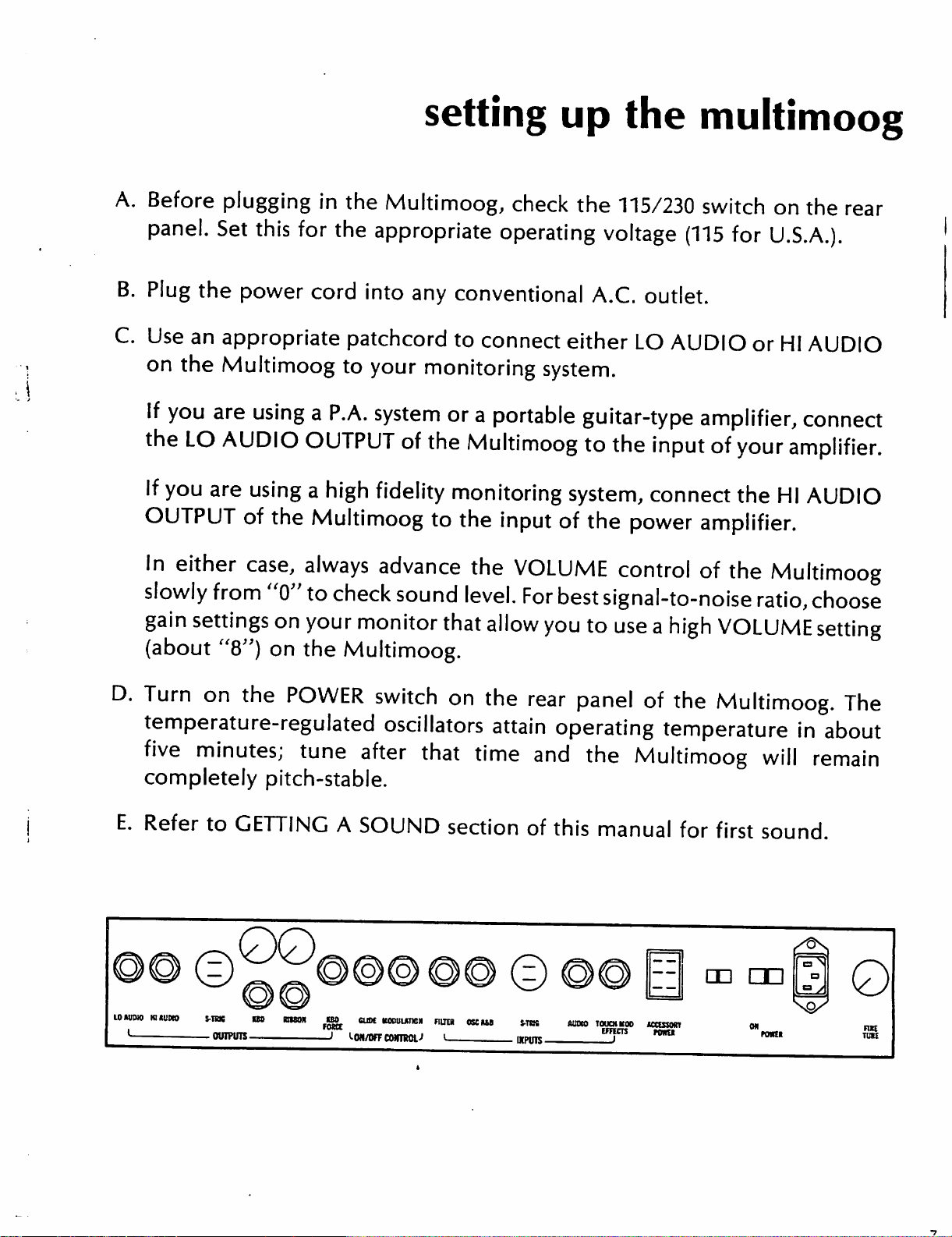
A.
Before
plugging
in
the
Multimoog,
setting
check
up
the
the
115/230
multimoog
switch
on
the
rear
panel. Set
B.
Plug
C.
Use
on
If
the
If
the
an
appropriate
the
Multimoog
you
are
LO
AUDIO
you
are
OUTPUT
In
either
slowly
gain
(about
from
settings
"8")
this
for
the
power
cord
patchcord
to
using
a
P.A.
OUTPUT
using
of
case,
a
high
the
Multimoog
always
"0"
to
check
on
your
on
the
Multimoog.
appropriate
into
any
your
system
fidelity
monitoring
or
of
the
monitoring
to
advance
sound
monitor
that
operating
conventional
to
connect
either
system.
a
portable
guitar-type
Multimoog
system,
the
input
the
level.
allow
of
VOLUME
For
best
you
voltage
A.C.
LO
to
the
the
power
control
signal-to-noise
to
use
(115
for
U.S.A.).
outlet.
AUDIO
or
HI
amplifier,
input
connect
of
your
the
amplifier.
HI
amplifier.
of
the
Multimoog
ratio,
a
high
VOLUME
AUDIO
connect
AUDIO
choose
setting
D.
Turn
temperature-regulated
five
completely
E.
Refer
on
the
POWER
minutes;
to
GETTING
tune
pitch-stable.
switch
after
A
SOUND
on
the
oscillators
that
attain
time
section
^00
lOAITOJO
HftUMO
S-TRK
—
OUTPUTS
OS
IBtBOR
ISO
SUM
rasa.
KOCUUTKN
l-Od/OFFCWIIROL-l
FI1TER
I—
OSCUB
S-TBG
ntPUlS-
rear
of
panel
operating
and
the
this
AUOW
TOUCH
of
the
temperature
Multimoog
manual
K00
tmm
for
KCBWRI
rant
Multimoog.
will
first
sound.
an
an
The
in
about
remain
0
FWE
TWEE
Page 7
Page 8
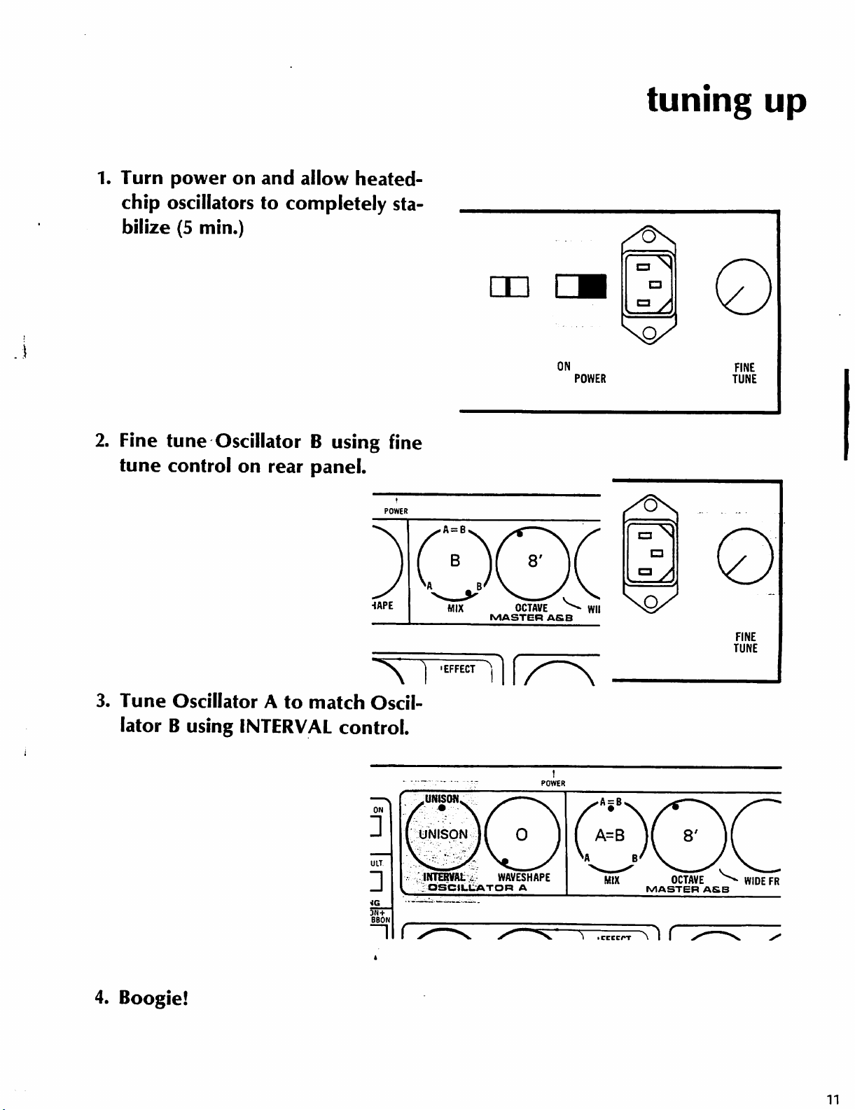
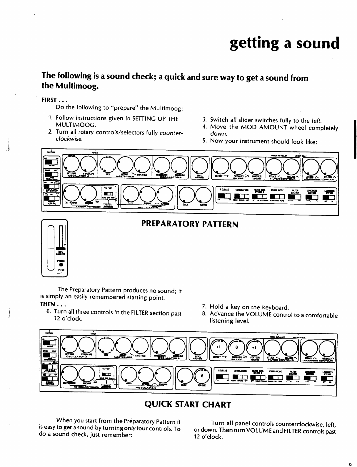
1.
Turn
power
on
and
allow
heated-
tuning
up
chip
oscillators
bilize
2.
Fine
tune
tune
control
to
completely
(5
min.)
Oscillator
on
rear
sta
B
using
fine
panel.
POWER
•iAPE
ON
OCTAVE ^ Wll
MASTER
ASB
POWER
□
FINE
TUNE
•"8s
FINE
TUNE
3.
Tune
lator
4.
Boogie!
Oscillator
B
A
using
INTERVAL
to
match
control.
Oscil
ON
ULT
INTERVAL . WAVESHAPE
H
BBON
OSCILLATOR
A
MIX
MASTER A&B
•CCCCPT\
I I
OCTAVE ^ WIDE
FR
ii
Page 9
sound
charts
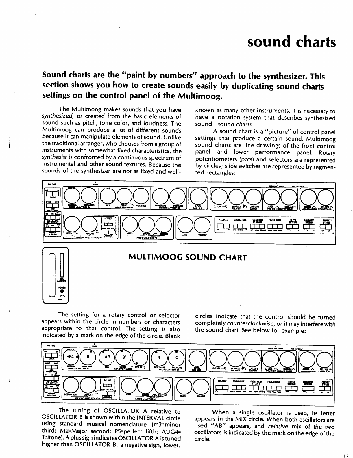
Sound
section
settings
synthesized,
sound
Multimoog
because
the
instruments
synthesist
instrumental
sounds
rm
charts
shows
on
The
Multimoog
such
as
can
it
can
traditional
with
is
confronted
of
the
oo
are
you
the
control
makes
or
created
pitch,
tone
produce a lot
manipulate
arranger,
and
synthesizer
who
somewhat
by a continuous
other
sound
coo
the
"paint
how
to
create
panel
sounds
from
the
color,
elements
chooses
fixed
textures.
are not
that
basic
and
loudness.
of
different
of
sound.
from a group
characteristics,
as
fixed
by
numbers"
sounds
of
the
Multimoog.
you
have
elements
spectrum
Because
and
of
The
sounds
Unlike
of
the
of
the
well-
approach
easily
known
have a notation
sound—sound
settings
sound
panel
potentiometers
by
ted
by
as
A
sound
that
charts
and
circles;
rectangles:
to
the
synthesizer.
duplicating
many
other
instruments,
system
charts.
chart
produce
are
line
lower
(pots)
slide
switches
that
is a "picture"
a
certain
drawings
performance
and
are
This
sound
describes
of
selectors
represented
mortem
charts
it
is
necessary
synthesized
of
control
sound.
Multimoog
the
front
control
panel.
are
represented
by
segmen
imortog
panel
Rotary
to
oqppoopQpq
^^^^^
□U
"»
rmrm
Him
am
on on
nu
e
i
nm
rm
an
nu
um
natai
cm
■—<-
«%
snua
DD
—>.
•>.
tmto
nil
on
a,
The
setting
appears
appropriate
indicated
within
by a mark
for a rotary
the
circle
to
that
@.OI®QQ1QQODQCDQ
The
tuning
OSCILLATOR
using
third;
Tritone).
higher
standard
M2=Major
A
plus
than
OSCILLATOR
of
B
is
shown
musical
second;
sign
indicates
MULTIMOOC
control
in
numbers
control.
on
the
The
edge
of
OSCILLATOR A relative
within
the
nomenclature
P5=perfect
OSCILLATOR
B; a negative
or
selector
or
characters
setting
the
is
also
circle.
Blank
to
INTERVAL
fifth;
circle
(m3=minor
AUG4=
A
is
tuned
sign,
lower.
SOUND
circles
completely
the
appears
used
oscillators
circle.
CHART
indicate
counterclockwise,
sound
chart.
CE
rmrmrm
'v " •«»
When a single
in
the
MIX
"AB"
appears,
is
indicated
that
the
See
below
••"«
on
en
suiinoM
oscillator
circle.
and
by
control
aanu
When
relative
the
should
or
it
may
for
example:
m
r»
^^
»»
is
used,
both
mix
mark on
the
be
turned
interfere
rrn
—v.
oscillators
of
edge
with
r
y\.
gn
its
letter
are
the
two
of
the
Page 10
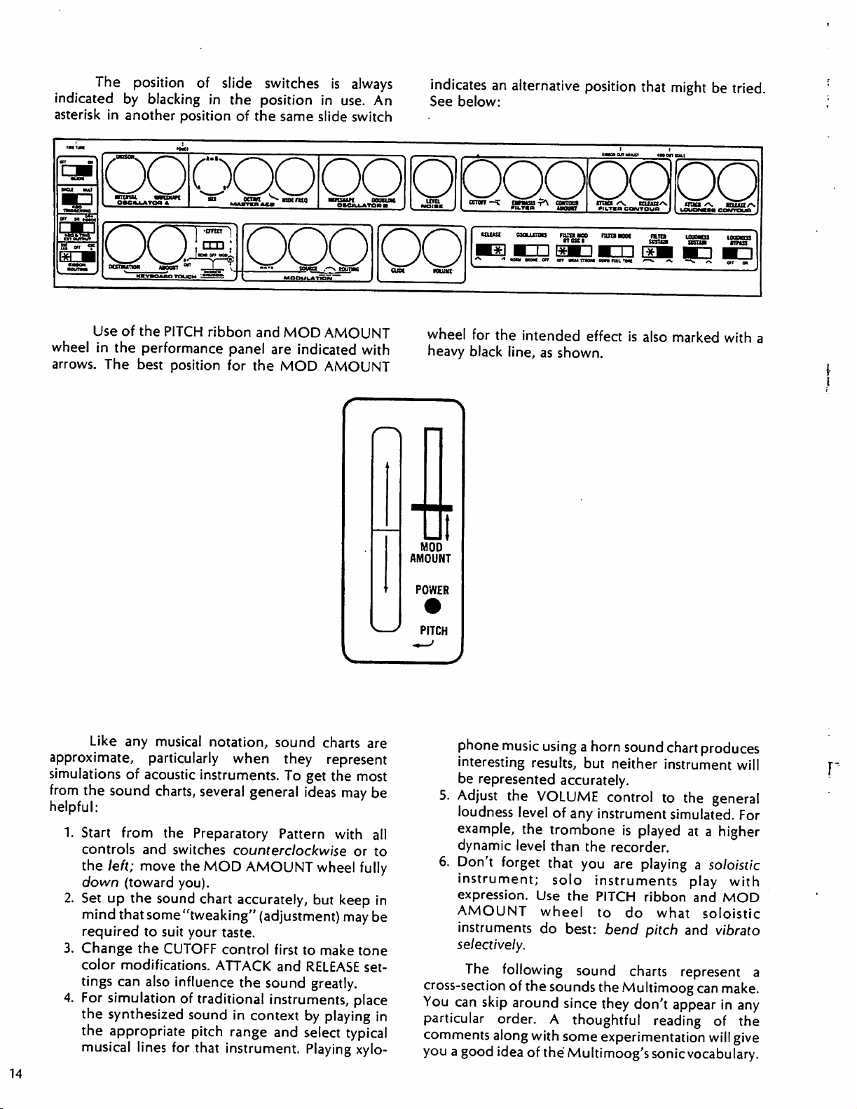
The
position
indicated
asterisk
by
blacking
in
another
of
slide
in
position
switches
the
position
of
the
in
same
slide
is
always
use.
An
switch
indicates
See
an
alternative
below:
position
that
might
be
tried.
oaciujiToa
Use
of
the
wheel
arrows.
in
the
The
best
a
PITCH
performance
position
fatATKH
^—^—
ribbon
AfcJI
and
MOD
panel
for
are
the
MOD
^^
OMGW.I
ATOffW"~
■
M^
Vh_S^5^«'
AMOUNT
indicated
with
AMOUNT
AMOUNT
POWER
Mamk
MOD
utOTf
^
must
wheel
heavy
for
black
^~\
QMSS
*^\
PJ^^W**
'
kbi
the
line,
COHTOOI
iMOWlT
ojojjjoo
tarn
err
on
intended
as
shown.
IiuCS
^>»
WfcTBB
CQWTQUfl
BMOO
FKJtlBOM
mma
mniM
effect
is
CCUJUt>Nt
1TTKB
LOUOMMS
also
marked
'N.
mm/v.
LUWIUIKI
with
a
Like
approximate,
simulations
from
the
sound
helpful:
1.
Start
controls
the
left;
down
2.
Set
up
mind
required
3.
Change
color
tings
4.
For
simulation
the
synthesized
the
appropriate
musical
14
any
musical
particularly
of
acoustic
charts,
from
the
and
move
(toward
the
sound
that
some
to
suit
the
CUTOFF
modifications.
can
also
lines
notation,
when
instruments.
several
Preparatory
switches
the
MOD
you).
chart
"tweaking"
your
taste.
control
ATTACK
influence
of
traditional
sound
pitch
range
for
that
instrument.
sound
they
To
general
Pattern
counterclockwise
AMOUNT
accurately,
(adjustment)
first
and
the
sound
instruments,
in
context
and
charts
are
represent
get
the
most
ideas
may
be
with
all
or
to
wheel
but
to
RELEASE
fully
keep
may
be
make
tone
set
in
greatly.
place
by
playing
select
in
typical
Playing xylo
PITCH
phone
interesting
be
5.
Adjust
loudness
example,
dynamic
6.
Don't
instrument;
expression.
AMOUNT
instruments
music
using
results,
represented
the
level
forget
accurately.
VOLUME
level
of
any
the
trombone
than
that
solo
Use
the
wheel
do
best:
selectively.
The
following
cross-section
You
can
particular
comments
you a good
of
the
sounds
skip
around
since
order. A thoughtful
along
with
some
idea of
the
Multimoog's
a
horn
sound
chart
produces
but
neither
control
instrument
the
recorder.
you
are
instruments
PITCH
to
bend
sound
the
they
experimentation
instrument
to
the
general
simulated.
is
played
playing
ribbon
do
pitch
charts
Multimoog
don't
at a higher
a
soloistic
play
with
and
MOD
what
soloistic
and
vibrato
represent
can
make.
appear
reading
sonic
in
of
will
give
vocabulary.
will
For
a
any
the
Page 11
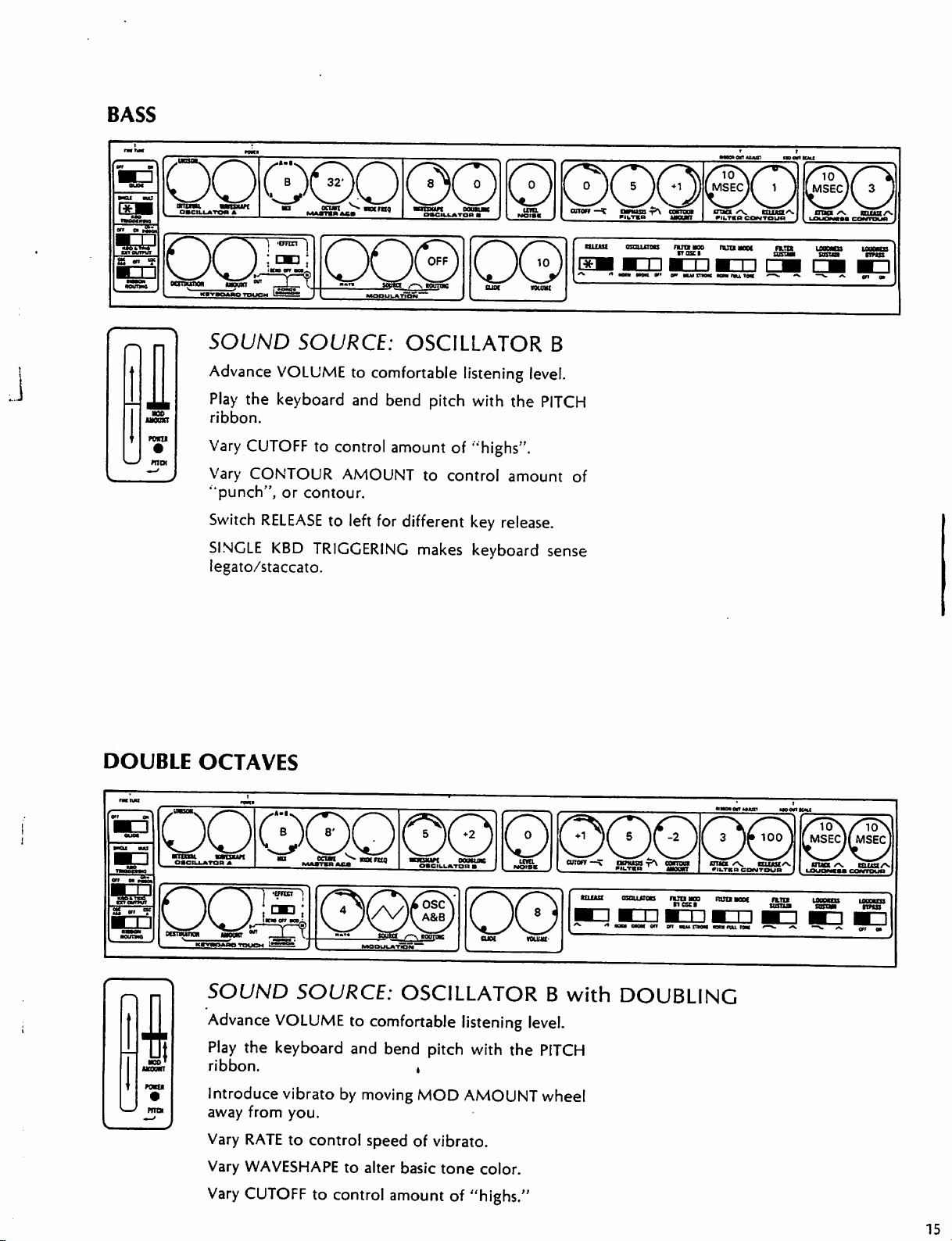
BASS
DOS
oanutiM
nxn
POTTO
mot
DOUBLE
OCTAVES
SOUND
Advance
Play
the
ribbon.
Vary
CUTOFF
Vary
CONTOUR
"punch",
Switch
SINGLE
legato/staccato.
SOURCE:
VOLUME
keyboard
or
RELEASE
KBD
to
and
to
control
AMOUNT
contour.
to
left
TRIGGERING
OSCILLATOR
comfortable
bend
amount
for
different
makes
listening
pitch
with
the
of "highs".
to
control
amount
key
release.
keyboard
B
level.
PITCH
of
sense
.
'SSS^rS?^
SOUND
Advance
Play
ribbon.
Introduce
away
Vary
Vary
Vary
-
^ssJ?**"**
SOURCE:
VOLUME
the
keyboard
vibrato
from
you.
RATE
to
control
WAVESHAPE
CUTOFF
to
control
^^a..^™*
OSCILLATOR
to
comfortable
and
bend
by
moving
speed
of
to
alter
basic
amount
listening
pitch
with
,
MOD
AMOUNT
vibrato.
tone
of
"highs."
^«l
B
level.
the
PITCH
wheel
color.
with
DOUBLING
Page 12
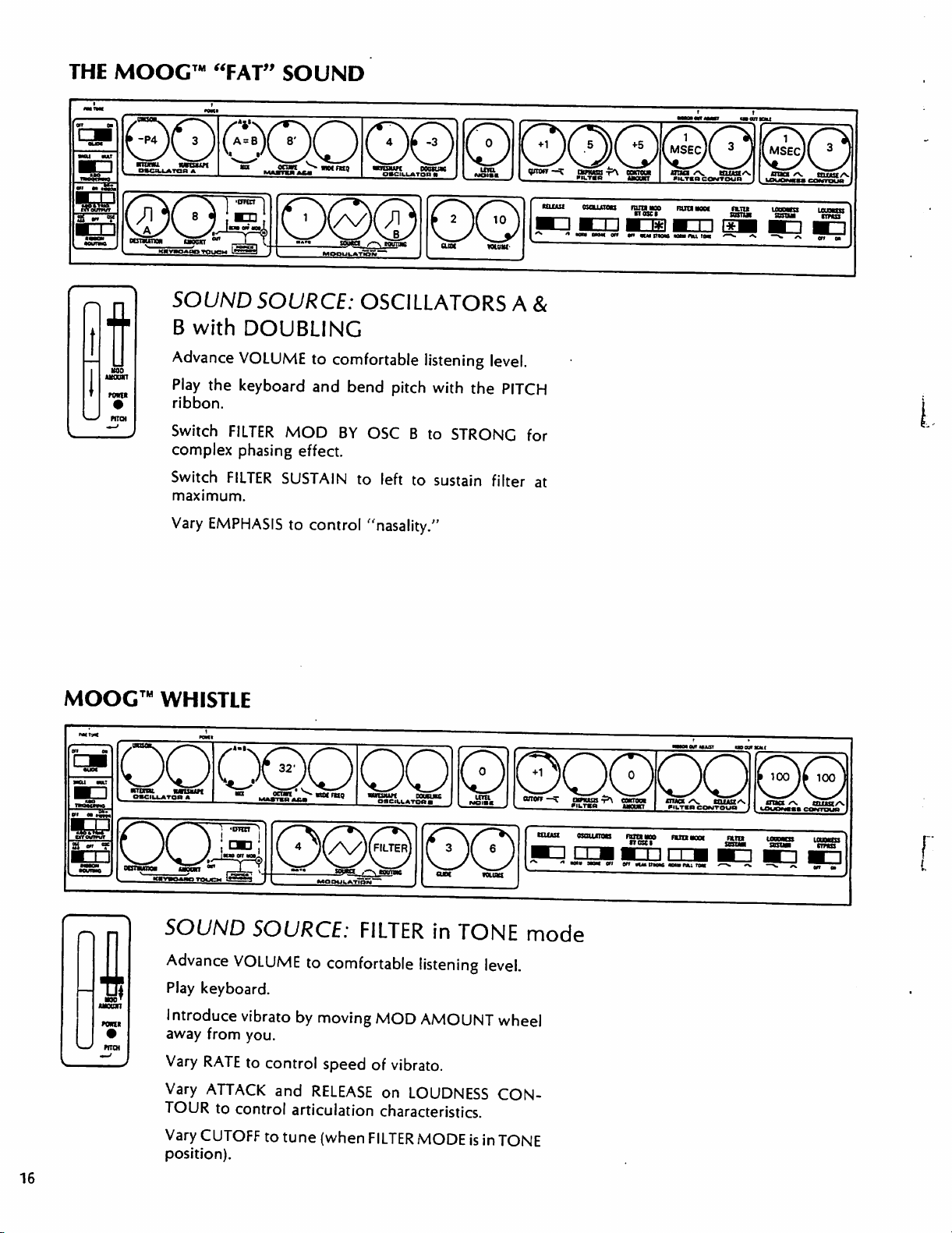
THE
MOOC™
"FAT"
SOUND
row*
PRCH
MOOG™
SOUND
B
with
Advance
Play
the
ribbon.
Switch
complex
Switch
maximum.
Vary
EMPHASIS
SOURCE:
DOUBLING
VOLUME
keyboard
FILTER
phasing
FILTER
SUSTAIN
WHISTLE
OSCILLATORS
to
comfortable
and
bend
MOD
to
BY
effect.
to
control
A
listening
pitch
with
OSC B to
left
to
sustain
"nasality."
level.
the
PITCH
STRONG
filter
&
for
at
16
MOD
moan
mat
SOUND
Advance
*
Play
Introduce
away
Vary
Vary
TOUR
Vary
position).
SOURCE:
VOLUME
keyboard.
vibrato
from
you.
RATE
to
ATTACK
to
control
CUTOFF
to
by
moving
control
and
RELEASE
articulation
to
tune
FILTER
comfortable
MOD
speed
of
on
in
TONE
listening
level.
AMOUNT
vibrato.
LOUDNESS
characteristics.
(when
FILTER
MODE
is
in
most
mode
wheel
CON
TONE
enturact
mum
numnoi
nun
r
Page 13
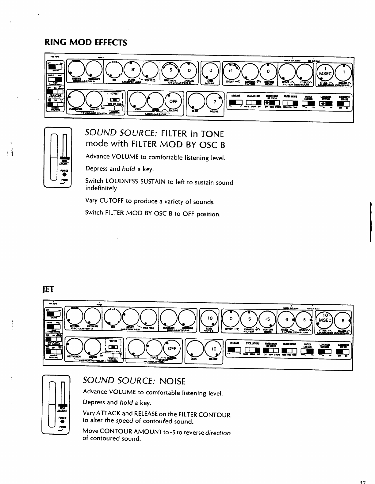
RING
MOD
EFFECTS
wnffliu
SOUND
mode
Advance
Depress
Switch
indefinitely.
Vary
CUTOFF
Switch
SOURCE:
with
VOLUME
and
LOUDNESS
FILTER
FILTER
to
comfortable
hold a key.
SUSTAIN
to
produce
MOD
BY
FILTER
MOD
in
BY
listening
to
left
to
a
variety
OSC B to
of
sounds.
OFF
©
PQOOQ
untua
TONE
OSC
sustain
position.
B
level.
sound
¥\
ukiuui
morioust
ocacioic
JET
BU
W
UUKKt
QOOQOOO
SOUND
Advance
Depress
Vary
ATTACK
to
alter
Move
of
contoured
SOURCE:
VOLUME
and
hold a key.
the
speed
CONTOUR
to
and
RELEASE
of
AMOUNT
sound.
NOISE
comfortable
on
contoured
to
listening
the
FILTER
sound.
-5
to
CONTOUR
reverse
direction
level.
Page 14
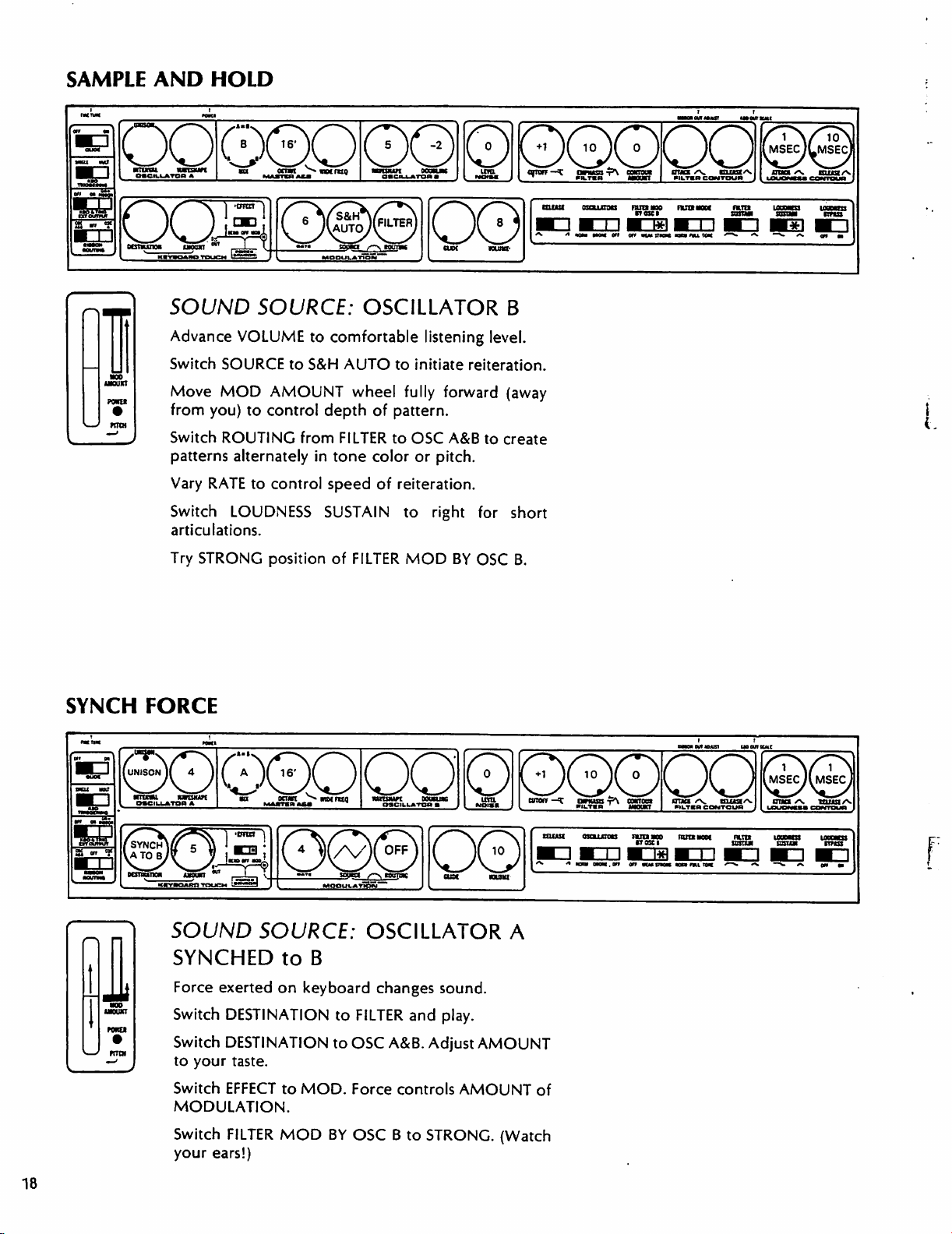
SAMPLE
AND
HOLD
ooe
■nmu.
wnstwi
B1CIUATOH
*
SOUND
Advance
Switch
TORI
row
Move
from
Switch
patterns
Vary
Switch
-1
'^'Ei
SOURCE:
VOLUME
SOURCE
MOD
you)
to
control
ROUTING
alternately
RATE
to
LOUDNESS
articulations.
Try
STRONG
position
ocfm
SS-=»
MOOUUATIOW
to
comfortable
to
S&H
AUTO
AMOUNT
wheel
depth
from
FILTER
in
tone
control
speed
SUSTAIN
of
FILTER
■ainwat
OO000OOO
o«cm-»roa» J I
OSCILLATOR
listening
to
initiate
fully
of
pattern.
to
OSC
color
or
of
reiteration.
to
MOD
woSt« ^ ^
■D M I I M
oo
«UK
^ ^ «qm
B
level.
reiteration.
forward
A&B
pitch.
right
BY
(away
to
create
for
short
OSC
B.
StrmS^
mom
orr
«Swn
1*1 ■ I
or*
«im
moM
nLTmcnmua
I
Mai
nu
xtm
irn
SBSCMI
ItfttS
SYNCH
FORCE
©000000000003
g
w
SOUND
SYNCHED
Force
Switch
Switch
to
your
Switch
MODULATION.
Switch
your
ears!)
SOURCE:
to
exerted
DESTINATION
DESTINATION
EFFECT
FILTER
on
taste.
to
MOD
MOD.
OSCILLATOR
B
keyboard
changes
to
FILTER
to
OSC
Force
BY
OSC B to
A&B.
controls
sound.
and
play.
Adjust
AMOUNT
AMOUNT
STRONG.
A
of
(Watch
nan
Kim
us
out
ma
18
Page 15
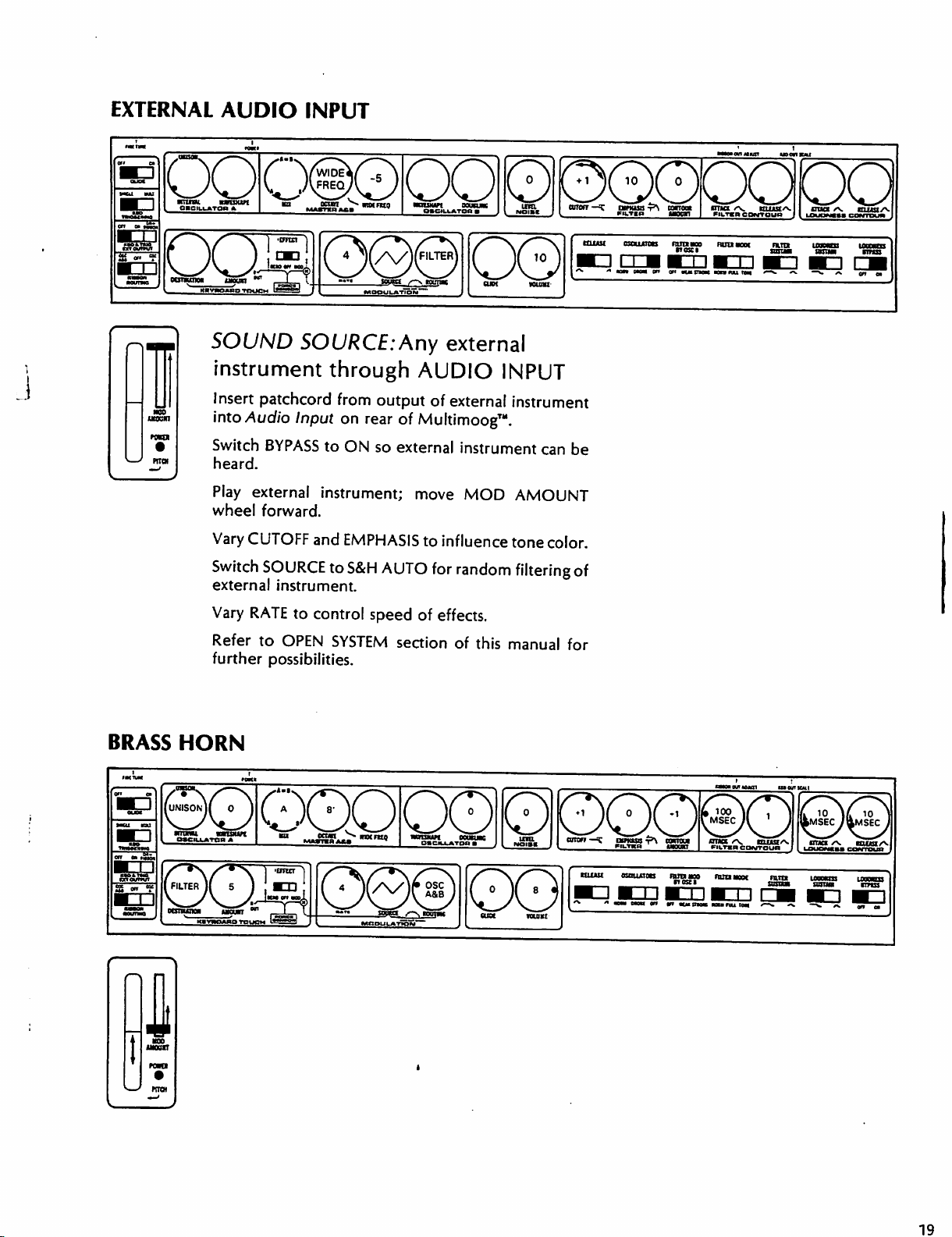
EXTERNAL
cm
a
AUDIO
INPUT
VSSSUrS?"'1
oos
SOUND
i
►own
instrument
Insert
into
Switch
heard.
Play
wheel
Vary
Switch
external
Vary
Refer
further
*="
m^S?«>■"«•
SOURCE:Any
through
patchcord
Audio
BYPASS
external
forward.
CUTOFF
SOURCE
instrument.
RATE
to
OPEN
possibilities.
from
output
Input
on
rear
of
to
ON
so
external
instrument;
and
EMPHASIS
to
S&H
AUTO
to
control
speed
SYSTEM
section
•fes'j^
^ffiL
00
am
^5^
wumr
external
AUDIO
of
external
Multimoog™.
move
to
influence
for
random
of
effects.
of
INPUT
instrument
instrument
MOD
this
can
AMOUNT
tone
color.
filtering
manual
txwat
be
of
for
liS^
tntncn
estuoMt
nF^
nmaao
tTOSCI
SS^^l^i
nunaaoc
oo
OTia
/N.
BUittA
tun
tanas
IIIIUM
OtRM
BRASS
HORN
UNISON
O»CIHATCn
V
n
NO
oqo
A
oqepoq@o
cum
J^fes—
mw
19
Page 16
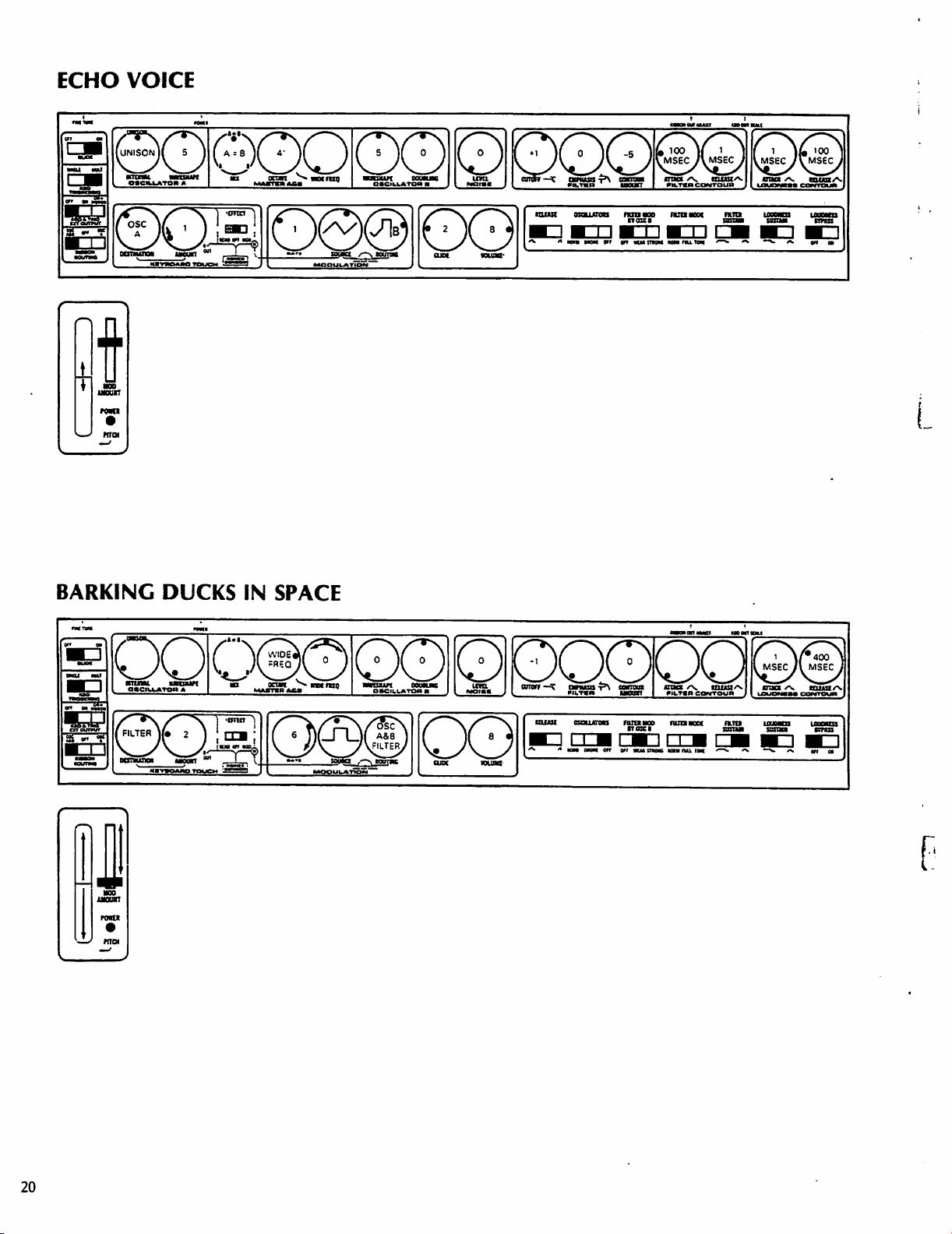
ECHO
k
±J
VOICE
0QOOOO
ta
ocon ^ mmo
MBOUUWIOM
■nstm
mmac
am
un
«ouna-
yt
«n
amtngM
mnuiM
ana
/v.
ouiaA
r
BARKING
DUCKS
oo
1
ram
IN
SPACE
0(5)0
oqppoopQ
ramaoec
fun
smut
loumdi
sun
iodcos
20
Page 17
J
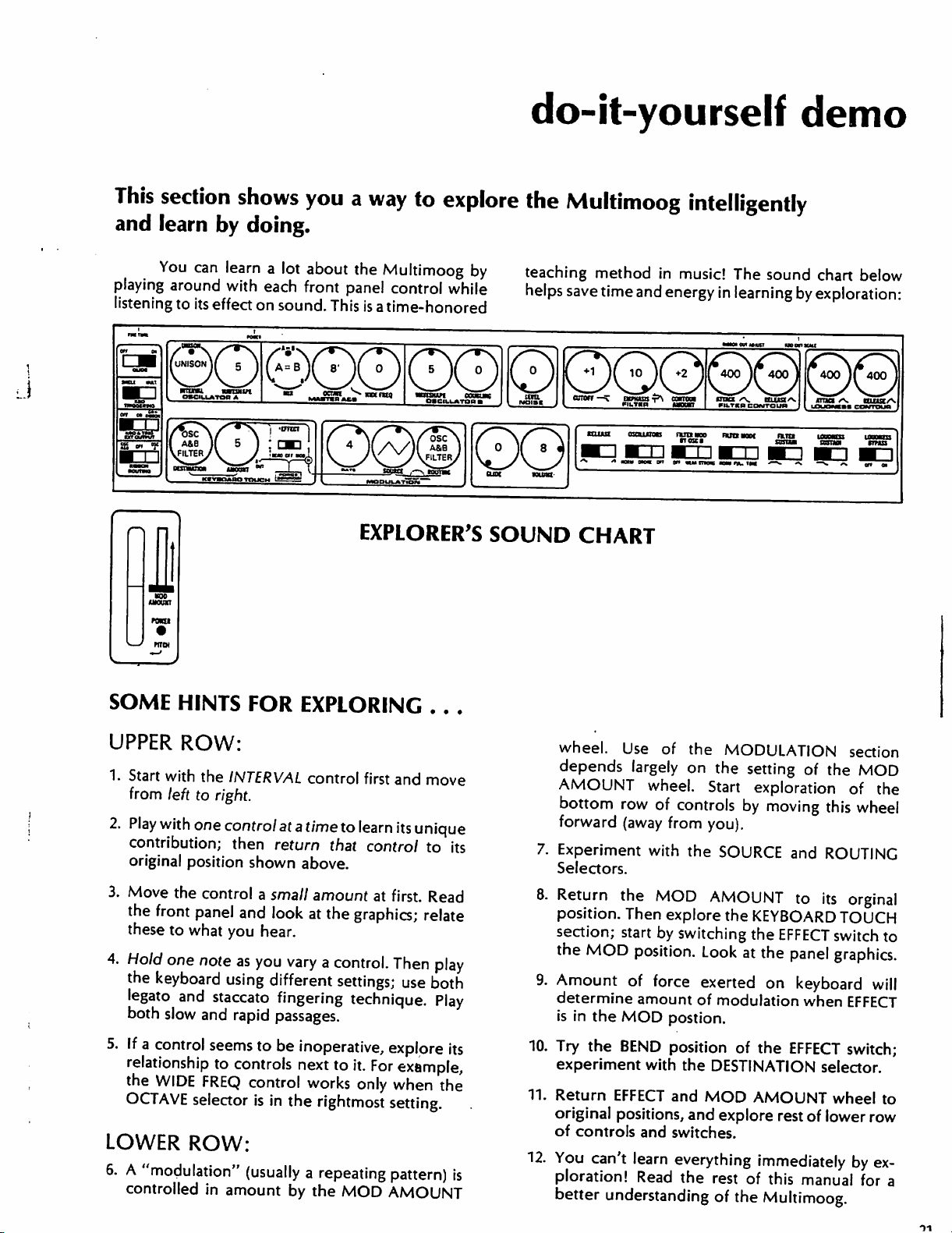
This
section
and
learn
You
playing
listening
by
can
learn
around
to
with
its
effect
shows
you
a
doing.
a
lot
about
each
on
front
sound.
the
panel
This
do-it-yourself
way
to
explore
Multimoog
control
is a time-honored
by
while
the
teaching
helps
Multimoog
method
save
time
and
ttuut
ascutma
■mcirn
intelligently
in
music!
energy
run
w»
The
sound
in
learning
wo
nun
woe
tnos
mm
mu
m
demo
chart
below
by
exploration-
rani
SOME
UPPER
1.
Start
from
2.
Play
contribution;
original
3.
Move
the
these
4.
Hold
the
legato
both
HINTS
FOR
ROW:
with
the
INTERVAL
left
to
right.
with
one
control
position
the
control
front
panel
to
what
you
one
note
keyboard
and
slow
using
staccato
and
at a time
then
return
shown
a
small
and
look
hear.
as
you
different
fingering
rapid
passages.
EXPLORER'S
EXPLORING
control
above.
amount
at
vary a control.
first
to
learn
that
control
at
the
graphics;
settings;
technique.
.
. .
and
move
its
unique
to
its
first.
Read
relate
Then
play
use
both
Play
SOUND
CHART
wheel.
depends
AMOUNT
bottom
forward
7.
Experiment
Selectors.
8.
Return
position.
section;
the
MOD
9.
Amount
determine
is
in
Use
of
the
largely
row
(away
the
Then
start
on
wheel.
of
controls
from
with
the
MOD
explore
by
switching the
position.
of
force
amount
the
MOD
postion.
MODULATION
the
setting
Start
exploration
by
you).
SOURCE
AMOUNT
the
KEYBOARD
Look
at
exerted
of
modulation
of
the
moving
EFFECT
the
on
this
and
ROUTING
to
its
panel
keyboard
when
section
MOD
of
the
wheel
orginal
TOUCH
switch
to
graphics.
will
EFFECT
5.
If a control
relationship
the
WIDE
OCTAVE
LOWER
6. A "modulation"
controlled
seems
FREQ
selector
to
be
inoperative,
to
controls
next
control
is
in
the
ROW:
(usually
in
amount
by
works
rightmost
a
repeating
the
to
it.
For
only
MOD
explore
its
example,
when
setting.
pattern)
AMOUNT
the
is
10.
Try
the
BEND
experiment
11.
Return
original
of
controls
12.
You
can't
ploration!
better
with
EFFECT
positions,
and
learn
Read
understanding
position
the
and
and
switches.
everything
the
of
the
EFFECT
DESTINATION
MOD
AMOUNT
explore
rest
of
rest
of
immediately
of
this
manual
the
Multimoog.
switch;
selector.
wheel
lower
to
row
by
ex
for
a
Page 18
guided
synthesizer
tour
This
SOUND
Multimoog,
sizers
"mechanical
longitudinal
air)
word
trumpet,
function:
air
disturb
and
"artificial"
sized
all
instruments
one
acoustic
the
A
properties
duration.
of
pitch,
thought
because
control
other.
instruments
is
construction,
for
high
the
relationship
sounds
brilliant.
have
section
features
GUIDED
exercises
Before
make
and
is
the
is
mechanical.
or a loudspeaker
they
molecules
the
cause
you
Sound
sound—only
sound
sounds
performer
musical
loudness,
somewhat
each
are
Although
sense
instruments.
sound
of
If
we
timbre,
Performers
to
acoustic
of
sound
The
pitch
notes
with
low
register.
tend
For
had
this
has
two
of
the
synthesizer
TOUR
that
AND
we
let's
it.
The
radiant
pressure
objective
are
(radiate
mechanism
to
is
sound
is
not a replacement
real.
both
ultimately
the
synthesizer
can
is
pitch,
think
it
is
simpler
and
the
presents
illustrate
SYNTHESIS
look
at
talk
about
dictionary
energy
waves
cause
The
body
mechanical
energy).
of
your
perceive
There
sound
acoustic
make
This
deal
with
traditionally
timbre
loudness.
have
individual
(tone
of
duration
to say
traditionally
instruments
properties
physical
dictates
integrated.
the
clarinet
register.
the
between
to
be
thousands
construction
that
control
For
has a characteristip
It
would
timbre
The
trumpet
timbre
mellow
of
years
characteristic
parts.
specific
sound
that
in a material
of
of a violin,
all
devices
ear
sound.
is
or
and
sound
is
very
difference
the
properties
defined
color),
that
properties
generally
independent
of
example,
normally
and
and
musical
integration
SOUND
and
specific
those
and
says
is
hearing."
serve
Air
affect
no
silence.
for a "real"
electronic
as
simply
musical
sound
be
loud
features.
features
how
that
sound
transmitted
medium
The
the
the
used
to
molecules
your
such
thing
A
musical
mechanically,
different
lies
in
the
of
as
having
loudness,
the
sound
given
of
don't
of
of
acoustic
properties
because
difficult
associated
has
a
built-in
loudness:
sounds
AND
discusses
features
of
the
synthe
is
by
(as
key
bell
of
a
same
disturb
that
brain
as
an
synthe
sound;
in
from
way
sound.
the
and
timing
has
little
sound,
allow
each
of
its
timbre
to
play
with
soft
are
instruments
of
control
of
SYNTHESIS
how
the
instruments
allow
Maybe
interest
done
tionized
electronic
cal
for
trumpets
in
independent
a
what
wrote
segregation
idea
tronically,
sounds
properties.
create a whole
composition
early
Buchla
designs
the
a
components
dent
These
may
variety
connect
(Even
Multimoog
panel
it
creates
of
the
properties
independent
that's
in
about
The
our
tendencies
artistic
can
the
final
brilliant,
early
"off
The
is
that
reconfigure
through
The
modern
1960's;
and
and
synthesizer
modular
and
variable
modules
be
interconnected
of
sounds.
modules
though
setting
deals
with
and
Multimoog
of
sound.
made
the
it.
rise
means
purpose.
but
composers
stage"
synthesizer
of
you
The
of
the
Robert
basic
synthesizer
of a stereo
to
is
of
metal
control
why
most
musicians
science
Electronics
of
concepts
of acoustic
be
recorded
mix.
control
quiet
of
sound—so
is
electronic
about
we
can
override
For
instance,
and
In
this
of
loudness
trumpet
tried
trumpet
parts?"
uses
the
properties
can
tear
the
its
functions,
the
independent
very
word
through
individual
elements.
synthesizer
acknowledged
A.
Moog.
ideas
have
industry.
Early
has
system,
control
handle
An
is
you
connect
still
electrical
in
different
inexpensive
with
cables
don't
use
its
sections,
often
referred
general
controls
and
You
and
wood
over
changing
technology
sound.
instruments—hopefully,
reduced
case,
and
sound.
to
achieve
electronics
of
synthesizer
"synthesize"
the
was
pioneers
In
become
versions
separate
that
over
and
called
patchcords
sound.
presents
just
can't
apart
sound
some
we
properties.
have
little
that.
has
Now,
of
screaming-loud
to a low
have
timbre
Maybe
when
to
sound.
The
apart
and
create
control
combination
developed
are
particular,
archetypal
weremodu/ar
modules,
offer
sound
properties.
signals;
ways
to
reliable
"patchcords."
a
given
to
as a "patch.")
tear
easily
to
had
little
could
the
achieved
be
revolu
with
physi
level
to
create
this
is
they
maximize
whole
elec
many
of
sound
means
to
or
in
the
Donald
Moog's
for
like
indepen
modules
create
with
a
way
to
the
control
Page 19
Synthesizers
—like
the
Multimoog—let
tions
(modules)
pots
(potentiometers)
purposes
think
of
learning
of
all
synthesizers
designed
of
the
instrument
instead
basic
specifically
you
"patch"
of
patchcords.
principles
as
having
for
together
using
switches
let's
continue
physically
stage
use
sec
and
But
for
to
separate
modules
modular
flexibility
and
have
requiring
patchcord
in
connection
Since
sound
loudness,
rrfodules
synthesizer
has
it
follows
dealing
patchcord
choice.)
the
properties of
that
with
connection.
still
offers
pitch,
the
synthesizer
each
property.
(The
maximum
timbre,
would
The
synthesizer
trical
signals—sound
make
sound,
generate
er
to
make
we
call
this
this
audio
audio
signal
source."
A
noise
that
take
the
with
it.
That
Further
parallels
at
least
an
electrical
sound—an
module
signal
generator
sound
mouthpiece
source
can
be
would
shaped
between
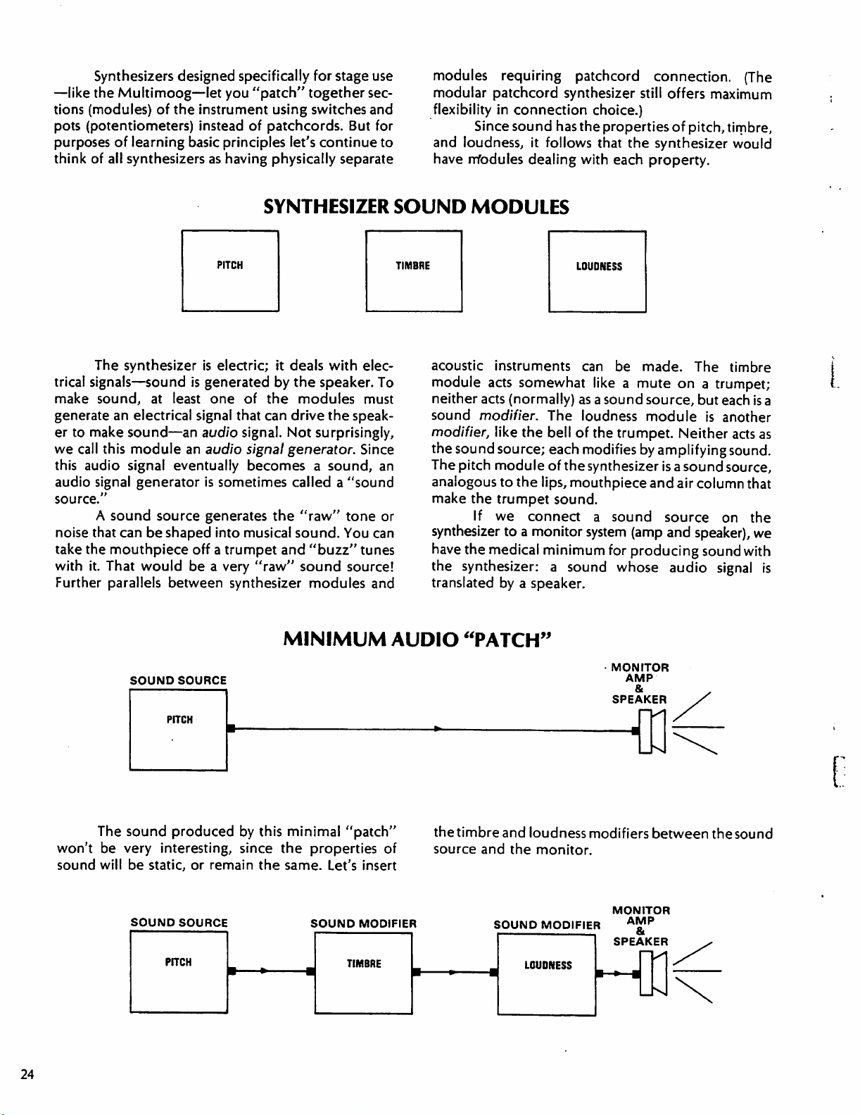
SYNTHESIZER
is
electric;
is
generated
one
signal
audio
an
audio
eventually
is
sometimes
generates
into
off a trumpet
be a very
synthesizer
it
deals
by
of
the
that
can
signal.
musical
Not
signal
generator.
becomes a sound,
the
and
"raw"
SOUND
TIMBRE
with
elec
the
speaker.
modules
drive
the
surprisingly,
called a "sound
"raw"
sound.
"buzz"
sound
modules
To
must
speak
Since
an
tone
or
You
can
tunes
source!
and
MODULES
acoustic
module
neither
sound
modifier,
the
The
analogous
make
synthesizer
have
the
translated
instruments
acts
somewhat
acts
(normally)
modifier.
like
sound
source;
pitch
module
to
the
trumpet
If
we
The
the
bell
each
of
the
the
lips,
sound.
connect a sound
to a monitor
the
medical
synthesizer:
minimum
a
sound
by a speaker.
LOUDNESS
can
be
made.
like a mute
as a sound
loudness
of
the
modifies
source,
module
trumpet.
by
synthesizer
mouthpiece
and
The
on a trumpet;
but
Neither
amplifying
is a sound
air
column
source
system
(amp
and
speaker),
for
producing
whose
audio
timbre
each
is
a
is
another
acts
as
sound.
source,
that
on
the
we
sound
with
signal
is
The
won't
sound
be
will
SOUND
sound
very
be
SOUND
SOURCE
produced
interesting,
static,
or
remain
SOURCE
MINIMUM
by
this
minimal
since
the
the
same.
AUDIO
"patch"
properties
Let's insert
SOUND
of
MODIFIER
"PATCH"
the
timbre
source
and
and
the
SOUND
MONITOR
AMP
&
SPEAKER
loudness
monitor,
MODIFIER
modifiers
MONITOR
AMP
SPEAKER
between
the
sound
24
Page 20
The
path
from
source
the
electrical
speaker.
audio
signal.
as
through
"audio
signal
signals
Notice
output
The
modifiers
well
as
an
audio
the
modifiers
path."
that
that
since
output
the
audio
The
are
to
the
it
actually
must
since
output
to
the
audio
signal
be
made
sound
source
generates the
have
both
the
audio
of
the
sound
speaker
audible
is
called
path
carries
by
the
has
only
an
audio
an
audio
input
signal
to
be
modified
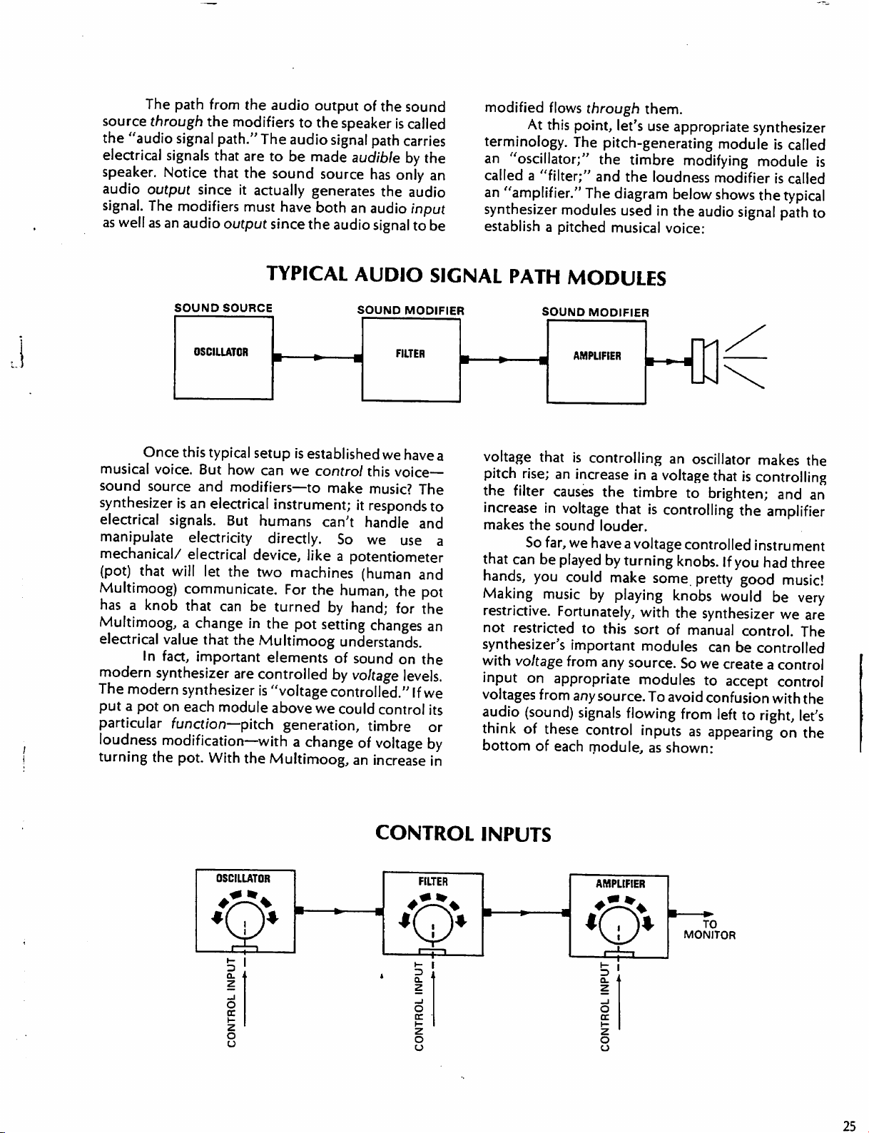
terminology.
an
called
an
"amplifier."
synthesizer
establish
flows
through
At
this
point,
The
"oscillator;"
a
"filter;"
modules
a
pitched
let's
pitch-generating
the
timbre
and
the
The
diagram
used
musical
them.
use
appropriate
modifying
loudness
below
in
the
audio
voice:
synthesizer
module
module
modifier
shows
the
signal
is
called
is
is
called
typical
path
to
Once
this
typical
musical
sound
synthesizer
electrical
manipulate
mechanical/
(pot)
Multimoog)
has a knob
Multimoog,
electrical
modern
The
put a pot
particular
loudness
turning
voice.
source
But
how
and
modifiers—to
is
an
electrical
signals.
But
electricity
electrical
that
will
let
the
communicate.
that
can
be
a
change
value
that
In
fact,
important
synthesizer
modern
synthesizer
on
each
function—pitch
in
the
are
module
modification—with
the
pot.
With
the
TYPICAL
setup
is
established
can
we
instrument;
humans
directly.
device,
two
Multimoog
controlled
is
like a potentiometer
machines
For
turned
the pot
elements
"voltage
above
generation,
a
change
Multimoog,
AUDIO
we
control
can't
the
setting
we
this
make
music?
it
responds
handle
So
we
(human
human,
by
hand;
changes
understands.
of
sound
by
voltage
controlled."
could
control
timbre
of
voltage
an
increase
SIGNAL
have
a
voice-
The
to
and
use
a
and
the
pot
for
the
an
on
the
levels.
If
we
its
or
by
in
voltage
the
increase
makes
that
hands,
Making
restrictive.
not
synthesizer's
with
input
voltages
audio
think
bottom
PATH
pitch
rise;
filter
can
MODULES
that
is
an
increase
causes
in
voltage
the
sound
So
far,
we
be
played
you
could
music
Fortunately,
restricted
to
important
voltage
from
on
appropriate
from
any
(sound)
of
signals
these
of
each
controlling
the
that
louder.
have
a
by
turning
make
by
playing
this
any
source.
flowing
control
module,
an
oscillator
in a voltage
timbre
is
controlling
voltage
some,
with
sort
of
modules
source.
modules
To
avoid
inputs
as
shown:
that
to
brighten;
controlled
knobs.
If
pretty
knobs
the
would
synthesizer
manual
can
So
we
create
to
accept
confusion with
from
left
as
appearing
makes
is
controlling
the
the
and
an
amplifier
instrument
you
had
three
good
music!
be
very
we
are
control.
be
controlled
The
a
control
control
the
to
right,
let's
on
the
OSCILLATOR
CONTROL
FILTER
INPUTS
■
•»
AMPLIFIER
Xj^/
5
a.
Z
o
cc
z
o
o
TO
MONITOR
25
Page 21
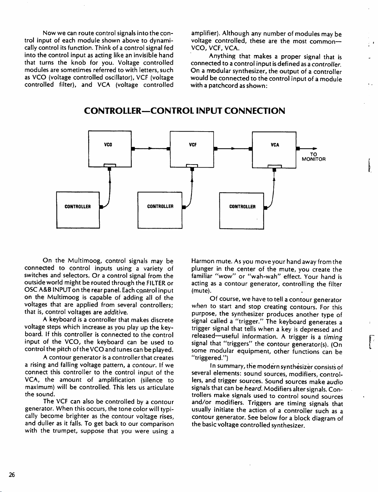
Now
we
can route
trol
input
of
each
cally
control
into
the
that
turns
modules
as
VCO
controlled
its
function.
control
are
(voltage
input
the
knob
sometimes
controlled
filter),
control
module
and
shown
Think
as
acting
for
you.
referred to
oscillator),
VCA
signals
of a control
like
Voltage
(voltage
into
the
above
to
dynami
signal
an
invisible
controlled
with
letters,
VCF
(voltage
controlled
con
hand
such
fed
amplifier).
voltage
VCO,
connected
On a modular
would be
with a patchcord
Although
controlled,
VCF,
VCA.
Anything
to a control
any
these
that
makes a proper
input
synthesizer,
connected
to
as
shown:
number
are
the
the
control
of
the
is
defined
output
modules
most
may
be
common—
signal
that
is
as a controller.
of a controller
input
of a module
CONTROLLER
On
the
Multimoog,
connected
switches
outside
OSC
A&B
on
the
voltages
that
is,
voltage
board.
input
control
a
rising
connect
VCA,
maximum)
the
sound.
generator.
cally
and
duller
with
to
control
and
selectors.
world might
INPUT
Multimoog
that
control
A
keyboard
steps
If
this
of
the
the
A
contour
and
this
the
The
become
the
trumpet,
on
are
voltages
which
controller
VCO,
pitch
of
generator
falling
controller
amount
will
be
VCF
can
When
as
this
brighter
it
falls.
CONTROLLER—CONTROL
VCO
CONTROLLER
control
inputs
Or a control
be
routed
the
rear
panel.
is
capable
applied
is a controller
increase
the
voltage
controlled.
also
suppose
from
are
additive.
as
is
connected
the
keyboard
VCO
and
is a controller
pattern,
to
the
of
amplification
be
controlled
occurs,
To
as
the
get
back
the
that
signals
using a variety
signal
through
Each
of
adding
several
that
makes
you
play
can
tunes can
a
control
This
lets
tone
contour
to
our
you
may
be
of
from
the
the
FILTER
control
all
controllers;
up
to
the
be
be
that
contour.
input
(silence
us
articulate
by a contour
color
voltage
comparison
were
or
input
of
the
discrete
the
key
control
used
to
played.
creates
If
we
of
the
to
will
typi
rises,
using
a
INPUT
VCF
Harmon
plunger
familiar
acting
(mute).
when
purpose,
signal
trigger
released—useful
signal
some
"triggered.")
several
lers,
and
signals
trollers
and/or
usually
contour
the
basic
CONNECTION
CONTROLLER
mute.
As
you
in
the center
"wow"
as a contour
Of
course,
to
start
the
called
signal
or
we
and
synthesizer
a
"trigger."
that
tells
J
move
of
"wah-wah"
generator,
have
stop
creating
when a key
information.
that
"triggers"
modular
I n summary,
elements:
trigger
that
can
be
make
signals
modifiers.
initiate
generator.
voltage
the
equipment,
the
modern
sound
sources.
heard.
sources,
Sound
Modifiers
used
Triggers
the
action
See
below
controlled
VCA
your
the
mute,
to
tell
produces
The
keyboard
contour
other
to
control
are
of a controller
for a
synthesizer.
TO
MONITOR
hand
away
from
the
you
create
effect.
controlling
a
Your hand
contour
generator
contours.
another
generates
is
depressed
A
trigger
is a timing
generator(s).
functions
synthesizer
modifiers,
sources
make
alter
signals.
sound
timing
signals
block
diagram
the
is
the
filter
For
this
type
of
a
and
(On
can
be
consists
of
control
audio
Con
sources
that
such
as
a
of
26
Page 22
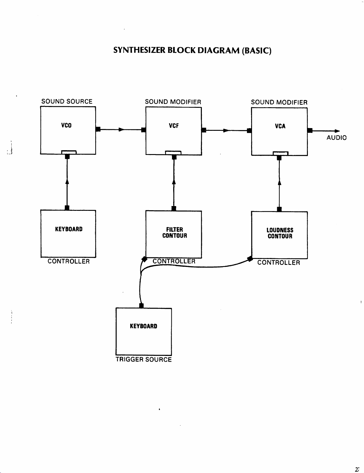
SYNTHESIZER
BLOCK
DIAGRAM
(BASIC)
SOUND
CONTROLLER
SOURCE
vco
KEYBOARD
SOUND
MODIFIER
VCF
FILTER
CONTOUR
CONTROLLER
SOUND
CONTROLLER
MODIFIER
VCA
LOUDNESS
CONTOUR
AUDIO
KEYBOARD
TRIGGER
SOURCE
Page 23
GUIDED
In
this
TOUR
sub-section
we
will
look
at
the
sound
sources,
modifiers,
controllers,
and
triggering
numbers"
time
(Set
instructions
SOUND
sections of
signals
pitched,
PITCHED
sound.
low
depends
pressure
you
attaching
regularly.
illustrating
you
the
individual
by
up
The
in
We
The
pitches.
probably
pedal,
spokes
devices
to
help
doing
the
Sound
found
explain
just
the
Chart
precisely
SOURCES
OSCILLATOR
the
Multimoog
order
to
clangorous
SOUNDS
hear
pitch
piccolo
Our
perception
mostly
waves
a
You
the
striking
on
strike
made a fake
piece
of
probably
an
interesting
higher
strokes
A
and
generate
create
(bell-like),
plays
cardboard
the
are
three
as
the
highness
high
of
how
frequently
our
ears.
"motor"
weren't
law
the
pitch
cardboard.
heard
exercises
for
pitches;
When
so
of
of
on
the
Multimoog.
specific
features.
before
that
precedes
best
B,
FILTER,
classes
and
pitch
for
the
aware
physics!
the
That's
more
results.)
and
NOISE
different
non-pitched.
or
the
is
complex,
and
you
your
spokes
that
sound
frequently—
audio
of
sound:
lowness
were a kid,
because
of
a
tuba
plays
but
regularly
bicycle
you
The
caused
by
struck
it
were
faster
by
the
Exercises
You
reading
each
literally,
is
second.
has a frequency
therefore
between
is
a
OSCILLATOR
Multimoog
and
oscillator
electrical
pitched
relationship
(OSCILLATOR
sound
might
the
GUIDED
exercise;
their
expressed
The
not
perfect,
higher
The
B,
with
sounds.
it
creates:
follow
frequency
in
"Hertz"
symphony
A=440
frequency
a
higher
pitch.
primary
are
two
associated
generates
patterns
The
between
B
are
presented
skim
through
TOUR
"by
the
the
first
thoroughly.
numbered
becomes
(abbreviated
orchestra
of
440
Hz.
Although
and
what
frequency
SECTION
sources
voltage
MASTER
periodic—regularly
that
the
speaker
following
the
frequency
in
this
case),
greater.
tunes
Hz;
standard
the
we
perceive
is
generally
of
pitched
controlled
A&B
exercise
and
Frequency
Hz),
or
cycles
per
to
an
"A"
that
tuning
correspondence
as
"pitch"
heard
sound
on
the
oscillators,
controls.
repeating—
can
translate
illustrates
of
an
the
pitch
Each
into
the
oscillator
of
the
is
as
A
28
EXERCISE
oo
4J
k
XJ
OOi
wrvo—o
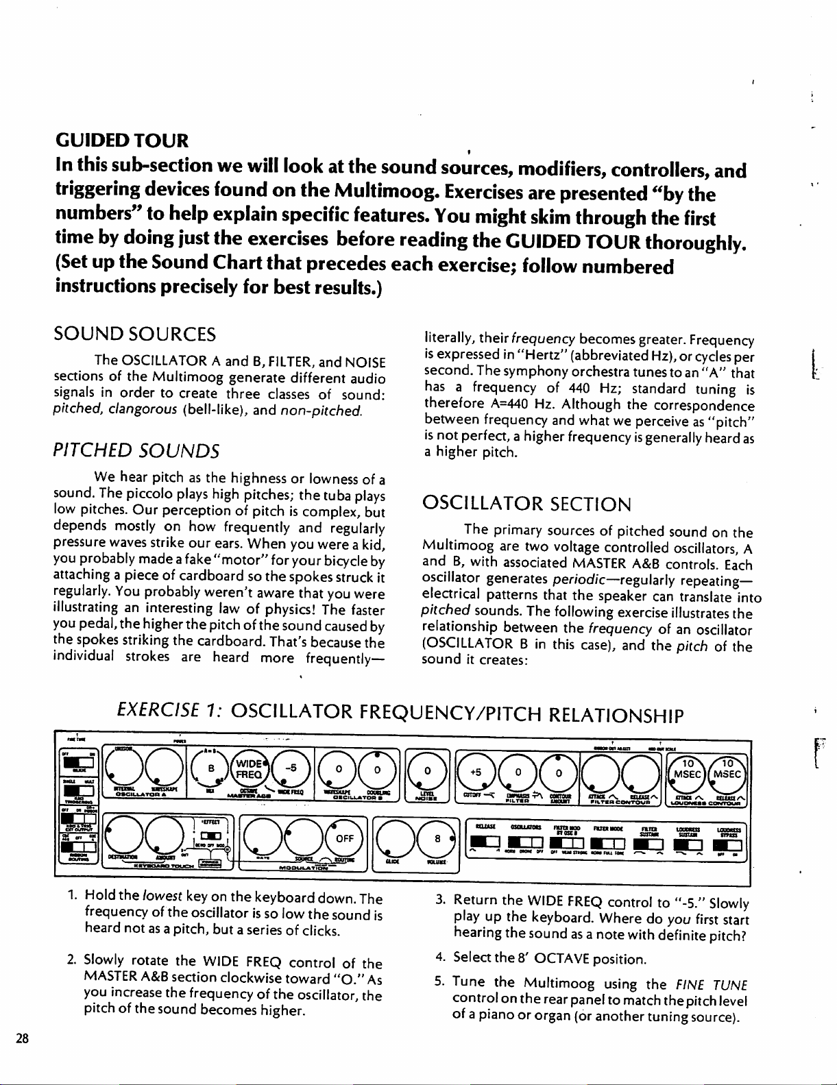
1.
Hold
the
lowest
frequency
heard
2.
Slowly
MASTER
you
increase
pitch
of
not
as a pitch,
rotate
A&B
of
the
1:
OSCILLATOR
touch
key
on
the
keyboard
the
oscillator
the
WIDE
section
the
frequency
sound
becomes
is
but a series
FREQ
clockwise
OBCIUUkTOB
down.
so
low
the
sound
of
clicks.
control
toward
of
the
oscillator,
higher.
of
"O."
FREQUENCY/PITCH
mu«
unuai
»ILT«P
I
RELATIONSHIP
P\
cwraa*
IMCUKl
«au««
Q0
The
is
the
As
the
3.
Return
play
hearing
4.
Select
5.
Tune
control
of a piano
the
up
the
the
the
the
on
WIDE
FREQ
control
keyboard.
sound
8'OCTAVE
Multimoog
the
rear
or
organ
Where
as
a
note
with
position.
using
panel
to
match
(or
another
muowtucowToup
35-
shim
to
"-5."
do
you
definite
the
thepitch
tuning
waaA
"gg.
susua
Slowly
first
start
pitch?
FINE
TUNE
level
source).
Page 24
6.
Hold
the
lowest
7.
Step
the
OCTAVE
positions
each
control
selector
8.
Return
Notice
WIDE
original
9.
Hold
10.
Move
toward
wise
OSCILLATOR B may
two
indicated
11.
Return
position.
and
rotate
position.
is
operable
is
in
the
the
OCTAVE
that
the
FREQ
control
tuning.
down a key
the
DOUBLING
the
"+5"
toward
octaves
"-5."
lower
by
panel
the
DOUBLING
key
on
the
keyboard.
selector
the
Notice
only
rightmost
selector
intervening
did
in
the
position;
Note
be
than
graphics.
through
WIDE
FREQ
that
the
WIDE FREQ
when
position.
not
middle
control
that
the
doubled
the
control
the
to
the
8'
movements
interfere
of
the
slowly
then
counterclock
pitch
sounded
either
primary
to
original
control
keyboard.
12.
all
of
its
for
OCTAVE
position.
of
the
with
the
clockwise
by
one
or
pitch,
as
"0"
13.
14.
15.
16.
17.
18.
Rotate
hear
Rotate
to
OSCILLATOR A relative
different
Play
FREQ
oscillators.
Rotate
OSCILLATOR B only.
the
Rotate
widely.
OSCILLATOR B or
Move
(Tunes
Turn
OSCILLATOR
(Tunes
the
MIX
control
both
oscillators.
the
INTERVAL
UNISON.
with
controls
the
DOUBLING
the
the
OSCILLATOR
MIX
OSCILLATOR A also.)
The
intervallic
the
MASTER
to
confirm
Return
MIX
control
control.
INTERVAL
(Has
no
FINE
TUNE
fully
counterclockwise
A.
to
control
INTERVAL
to
OSCILLATOR
tunings.
A&B OCTAVE
that
OCTAVE
fully
Introduce
control
effect
its
Move
on
doubling.)
control
B.)
FINE
the
of
they
to
8'.
clockwise
on
on
A=B
position
OSCILLATOR
control
and
control
doubling
OSC!
LLATOR
the
tuning
the
rear
to
TUNE
to
A
tunes
B.
Try
WIDE
both
to
hear
using
A
of
panel.
listen
to
control.
iwcu
mm
TmJS&mg
LLJJ
MM
oscillators
on
OSCILLATOR
only
octave
borrowed
lengths,
keyboard
of
tuning
octaves.
be
UUQQQPQIPPQPpQpO
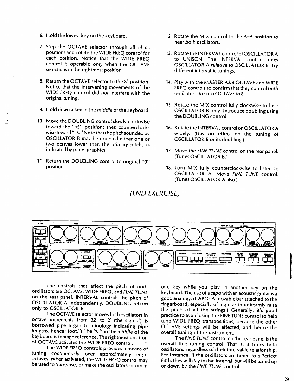
The
controls
are
OCTAVE,
the
rear
panel.
A
to
OSCILLATOR
The
OCTAVE
increments
pipe
hence
is
footage reference.
OCTAVE
used
activates
The
WIDE
continuously
When
to
transpose,
that
INTERVAL
independently.
selector
from
organ
"foot.")
the
FREQ
activated,
or
'
QQQPO
affect
WIDE
B.
32
terminology
The
WIDE
controls
over
the
make
the
pitch
FREQ,
and
FINE
controls
the
DOUBLING
moves
to
2/
both
oscillators
(the
sign
indicating
"C"
in
the
midctle
The
rightmost
FREQ
provides
position
control.
a
means
approximately
WIDE
FREQ
control
the
oscillators
sound
(END
of
EXERCISE)
**^iww j V
both
TUNE
pitch
of
relates
in
(')
is
pipe
of
the
of
eight
may
in
W>OI»K / L
one
key
keyboard.
good
analogy.
fingerboard,
the
pitch
practice
tune
WIDE
OCTAVE
overall
The
overall
oscillators,
For
instance,
Fifth,
they
or
down
niTgn
must
while
The
—OUT
osaum
mm
n^rrrn
you
use
of a capo
(CAPO: A movable
especially
of
all
the
to
avoid
using
FREQ
transpositions,
settings
tuning
FINE
fine
regardless
willstay
by
will
of
the
instrument.
TUNE
tuning
control.
of
if
the
oscillators
in
that
the
FINE
TUNE
vcLTsa
contour . uouowtai
wo
ruawoc
nzi
CQ
play
in
another
with
an
acoustic
bar
attached
of a guitar
strings.)
the
FINE
be
affected,
control
their
interval,
to
uniformly
Generally,
TUNE
control
because
and
on
the
rear
That
is,
it
intervallic
are
tuned
but
will
control.
coNreun
rrn
key
on
the
guitar
is
a
to
the
raise
it's
good
to
help
the
other
hence
panel
tunes
the
is
the
both
relationship.
to a Perfect
be
tuned
up
29
Page 25

The
INTERVAL
relative
violin
tune
then
to
OSCILLATOR
strings).
OSCILLATOR B using
tune
The
For
proper
OSCILLATOR
DOUBLING
control
tunes
B,
over a span
tuning
A
to
control
of
the
FINE
match
OSCILLATOR
isn't
OSCILLATOR
of
±P5
the
instrument,
TUNE
really
a
A
(like
control;
B.
tuning
control.
one
DOUBLING
OSCILLATOR
controls
It is
a
panpot
or
two
octaves
You
can
to
produce
can't
B.
use
that
mixes
in
a
tonethat
lower
get
the
"parallel
than
OSCILLATOR
"out
INTERVAL
of
tune"
and
chords,"
for
is
either
B
with
DOUBLING
example:
GIVEN
WHEN
generated
pattern."
waveshape
waveshape
a
synthesizer
Most
waveshape
timbre,
THIS
YOU
So
far,
This
traditional
or
tone
TUNING:
.UNISON
INTERVAL
OSCILLATOR
PLAY:
we've
by an
is
of
that
oscillator
pattern
simply
acoustic
may
be
instruments
helps
color.
WAVESHAPE
A
ts:
referred
is
a
way
instruments
observed
us
The
to
the
only
as
called
of
a
piauring
or
on
have
identify
Multimoog
that
MIX
audio
an
"electrical
"waveshape."
a
sound;
the
oscillator
an
oscilloscope.
a distinctive
instrument's
has
oscillators
OCTAVE ^ WIDEFREQ
MASTER
signal
A
the
of
ASB
YOU
that
HEAR:
produce
translated
timbres.
same
waveshape
instrument
considered),
waveshapes
sound
chart
V
electrical
by
the
If
a
signal
as a sound
(other
factors
their
can
have
and
let's
WAVESHAPE
OSCILLATOR
DOUBLING
B
waveshapes
speaker
generated
sounds
listen:
into a wide
by an
oscillator
created
such
will
different
by a traditional
as
attack
be
similar.
timbres;
which
variety
and
are
of
has
the
release
Different
set
up
the
30
EXERCISE
1.
Hold
any
key
on
listening
waveshape.
2.
Slowly
control
"5-6"
waveshape.
various
to
the
rotate
you
the
through
will
hear
As
you
"rectangular"
2:
OSCILLATOR
the
keyboard
sound
OSCILLATOR
its
positions.
the
sound
move
toward
waveshapes.
down.
of a "sawtooth"
B
WAVESHAPE
Between
of
the
"10,"
WAVESHAPE/TIMBRE
You
positions
"square"
you
(END
are
3.
Look
control.
shapes.
4.
Move
regularly
hear
When
to
control
create
EXERCISE)
RELATIONSHIP
at
the
panel
graphics
The
waveshapes
the
WAVESHAPE
above
the
be
"dynamic."
oscillator
dynamic
and
waveshape
Later
waveshape
waveshapes
for
the
WAVESHAPE
are
named
control
below,
changes
you'll
smoothly
say,
position
like
this
learn
with a voltage
automatically.
after
their
and
"5."
it
is
said
how
to
to
r
Page 26

The
differences
various
harmonic
as a
Most
"fundamental/'
often
the
frequency
called
relationship
fundamental
of
100
number
Hz.)
reinforce
waveshapes
structures.
collection
pitched
of
simple
sounds
and
not
as
loud.
upper
partials
of
the
"harmonics."
to
each
frequency
simple
sounds
Hz, 200
Hz,
(sine
300
multiples
Upper
partials
our
perception
that
are
A
waveshape
components
consist
other
partials
When
are
the
whole
fundamental,
(They
other.)
of
waves)
Hz,
400 Hz,
of
the
fundamental
that
you
hear
among
due
to
their
different
may
bethought
called
"partials."
of a first
frequencies
number
That
100
partial
that
called
are
higher
(pitches)
multiples
all
the
partials
are
in a harmonic
is, a tone
Hz
may
be
composed
having
and
so
the
frequencies
forth.
(Whole
frequency
are
harmonic
of
the
tend
fundamental
the
of
the
and
of
of
the
are
with
a
100
to
frequency
relative
spectrum—accounts
timbre,
tinuous
harmonic
waveshapes
harmonic
in
bar
bar
along
harmonic;
relative
are
following
some
the
first
as
the
"pitch"
strengths
or
distinctive
Each
WAVESHAPE
selection
spectra,
are
of
or
the
spectrum
graph
form
as
the
horizontal
the
height
strength of
also
indicated
graphs
of
the
ten
depict
waveshapes
partials
we
hear.
of
harmonics—the
in
part
for
tone
color
control
waveshapes
arrangements
basic
timbral
of a waveshape
shown
below.
indicates
of
that
that
harmonic.
with
fractions
the
available
of a tone
of
The
presence
harmonic
our
perception
of
instruments.
provides
of
a
con
with a variety
of
partials.
building
is
often
The
the
presence
bar
represents
(Relative
or
decimals).
harmonic
on
the
100
Hz
are
These
blocks.
depicted
position
strengths
spectra
Multimoog;
depicted:
and
the
of
The
of
a
of
a
the
The
for
WAVESHAPE
WOE
RECTANGULAR
RELATIVE
H: 0 100
HARMONIC
200
3OC
400
SOO
■5
J
0
!0O
200 300
400
^30
I
Hj 0 100
200 300
I •
400
500 600 700
16
"7
600
700
I
600
700
J_
.* I I
I
CONTENT
i/e
1.-9
,,,c
BOO 900
1000
800
900
1000
•«»
i
900
I
1000
800
Each
oscillator
sawtooth
waveshape
bottom
sawtooth
useful
square
and
rectangular
is a rectangular
are
of
equal
/I
waveshape
in
producing
string
waveshape
on
the
Multimoog
waveshapes.
waveshape
width.
iTl
As
the
has
all
and
brass-like
has
only
MARROW
RECTANGULAR
generates
A
square
whose
graphs
harmonics;
top
and
show,
the
it
is
sounds.
The
odd-numbered
(1,3,5,7,
"hollow"
As
sided)—
spectrum
"nasal"
double-reed
0
100
200
300
400
etc.)
harmonics;
sounding
the
rectangular
|~~1_
changes
sounds
instruments
wave
,
f]
in a complex
useful
instruments.
500
600
700
800
it
is
becomes
,
|[_
for
simulating
900
1000
used
to
simulate
such
as
the
clarinet.
asymmetrical
,
—
its
harmonic
manner,
single
(lop-
producing
and
31
Page 27

.UNISON,
INTERVAL
OSCILLATOR
Each
WAVESHAPE
selection
that
provides
moved
with a narrow
the
rectangular
waveshape,
top.
produced,
"10/'
rectangular
rectangular
never
Multimoog
and
mixture
OSCILLATOR
the
clockwise
section.
sawtooth
this
rectangular
WAVESHAPE
Between
and
the
square
"disappear"
control
wave
and
the
positions
as
the
waveshape
waveshape.
waveshape
at
provides a variety
EXERCISE
W/WESHAPE
A
control
of
the
The
waveshape;
sawtooth
allows
waveshapes
position
as
waveshape
waveshape
is
moved
widens,
sawtooth
"5-6" a square
control
narrows
The
is
limited
any
WAVESHAPE
toward
becomes a square
disappears
is
moved
to a very
narrowness
so
the
of
3:
FILTER
MIX
continuous
produced
marked
the
control
(about
from
waveshape
on
sound
position.
waveshapes:
by
"O"
is
is
mixed
"2").
As
"5,"
the
the
is
toward
narrow
of
this
will
The
AS
SINE
section
a
placed
generates
has
proceed:
WAVESHAPE
WAVESHAPE
OSCILLATOR
sawtooth,
of
sawtooth
understanding
is
very
eventually
best
FILTER
sound
square,
useful
teaches
for
an
intended
variable
and
variable
of
the
harmonicspectra
in
sound
you a lot
sound.
SECTION
Although
is
tone
source.
in
a
no
harmonics.
the
primary
modification,
When
the
TONE
sine
waveshape
position,
Set
rectangular,
rectangular
synthesis.
about
AS
the
(a
up
OSCILLATOR
DOUBLING
B
and a mixture
waveshapes.
of
waveshapes
Also,
experience
which
SOUND
function
the
FILTER
FILTER
the
whistle-like
the
waveshape
SOURCE
of
the
will
also
MODE
FILTER
sound)
sound
chart
An
FILTER
act
switch
section
that
and
is
as
is
32
1.
Play
the
keyboard.
of a sine
FILTER
2.
Place
position.
the
The
when
prevents
performance!
3.
Try
the
FILTER
4.
Return
waveshape
section.
the
FILTER
Play
the
FILTER
FILTER
different
MASTER
MODE
section
this
switch
filter
settings
A&B
as
well
OCTAVE
You
are
listening
that
MODE
keyboard
switch
switch
to
becomes
is
in
the
"howl"
of
the
section.
as
the
oscillators.)
to
32'
position.
to
the
is
produced
to
the
NORM
(no
sound).
the
TONE
a
sound
TONE
accidents
OCTAVE
(OCTAVE
Return
position.
source
position;
selector
tunes
(END
sound
by
the
only
this
in
in
the
OF
EXERCISE)
5.
Hold
any
key
on
CUTOFF
FILTER
CUTOFF
control.
6.
Play a short
different
that
pitch
adds
produced.
7.
Notice
used
switch
only
control
section
control
Play
with
melodic
settings
the
same
levels.
to
The
the
that
the
as a sound
is
in
the
the
FILTER
the
keyboard
over a wide
is
in
acts
as a wide
the
OCTAVE
the
TONE
down.
span.
control
fragment
of
the
CUTOFF
melody
keyboard
source
section
is
produced
position
OSCILLATORS
OFF
of
the
CUTOFF
to
establish
since
the
position.
in
You
TONE
Rotate
When
mode,
span
the
the
the
tuning
again.
repeatedly.
control.
at
Try
Note
different
control
the
pitch
are
not
being
OSCILLATORS
have
heard
mode.
Page 28

In
the
previous
actually
the
OSCILLATORS
even
OSCILLATORS
because
to
alone.
not
audio
hear
signal
when
we
don't
the
turned
we
sound
exercise,
"off,"
path
generate
choose
switch
want
but
so
we
audio
not
to
is
placed
to
hear the
produced
the
OSCILLATORS
simply
don't
signals
removed
hear
continuously-
listen
to
in
the
OFF
oscillators,
by the FILTER
FILTER/OSCILLATOR
SYNCHRONIZATION
Some
either/both
unusual
oscillators
sounds
and
can
the
FILTER
be
section
are
from
them.
them.
The
The
position
but
wish
section
made
if
are
used
as
sound
done,
the
together
multiples)
control
pitch
to
as
the
fundamental.
FILTER
of
CUTOFF
the
oscillator(s).
synchronization
section:
sources
filter
can
at
harmonic
to
the
tune
the
oscillator,
The
to
simultaneously.
be
"synchronized,"
intervals
oscillator.
FILTER
OCTAVE
move
The
of
an
If
section
they
will
selector
in
octaves
following
oscillator
When
or
(whole
you
use
to
sound
be
"synched"
will
as
well
exercise
and
number
the
CUTOFF
the
cause
as
the
illustrates
the
this
is
locked
same
at
the
the
pitch
FILTER
EXERCISE
ecu
hi
QQ|OQO|0GIPg)O.Gpa
:u
ioftraa^
XJ
MVTMtXTWia
1.
Note
sections
OSCILLATORS
FILTER
2.
Hold
3.
Adjust
beating
4.
Play
the
sections
iimhm
that
both
are
MODE
down a key
the
CUTOFF
disappear
keyboard.
are
"synched"
4:
OSCILLATOR/FILTER
Wt
j
'
OSCILLATOR
used
switch
as
switch
is
is
to
in
the
middle
control
(should
The
OSCILLATOR
at
MQPUUTIpN
B
and
sound
set
to
NORM,
TONE.
of
until
be
around
the
fundamental.
00
cum
the
FILTER
sources:
the
keyboard.
growling
and
the
and
the
and
"O.")
FILTER
SYNCHRONIZATION
iCWTJajtfli
MDCPTXm
hoc
tn
on
•utma*
rournt
5.
The
FILTER
harmonic
move
controlling
When
synchronized
frequency.
6.
Try
different
the
oscillator.
section
of
the
the
CUTOFF
the
the
beats
to a harmonic
CUTOFF
Play
aoaifour»
may
be
synchronized
oscillator
frequency
disappear,
frequency.
control
of
the
the
FILTER
of
settings
the
keyboard.
that
at
a
Slowly
clockwise,
FILTER
section.
section
the
oscillator
"synch"
is
with
When
the
pitch
about
"O"),
shown
fundamental
the
exercise:
When
it
becomes
conjunrtion
added,
have
four
the
pitch
of
the
OSCILLATOR
and
both
above,
they
frequency
the
FILTER
another
with
and
both
tones
sound
the
oscillators
which
of
oscillators.
the
FILTER
are
used
are
synchronized
of
the
section
source.
are
will
follow
section
B
section
as
oscillator.
is
in
When
used,
(CUTOFF
sound
sources
Continue
the
TONE
It
may
be
DOUBLING
it
is
possible
the
keyboard
matches
to
as
at
the
(END
used
EXERCISE)
mode,
in
is
to
in
parallel.
produces
strange
which
useful
7.
Move
from
lower
should
OSCILLATOR B and
section.
the
DOUBLING
"O."
This
provides
than
the
pitch of
now
hear
The
oscillators
the
fourth.
interval,
to
synch
settings.)
(If
the
filter
to;
experiment and
control
clockwise
a
tone
OSCILLATOR
three
produce
you
may
tones:
one
from
three
tune
the
become
you'll
away
two
octaves
B.
You
two
from
the
FILTER
and
the
filter
oscillators
confused
to
a
as
to
find
the
33
Page 29

CLANGOROUS
So-called
characterized
characteristic
partials
not
that
stand
as
feature
are
not
in
whole
SOUNDS
clangorous
being
metallic
of a bell
harmonic.
number
sound
sounds
or
That
relationships
are
often
"bell-like."
is
the
presence
is,
partials
to
A
of
that
do
each
other.
in
MOD
give
The
clangorous
On
the
Multimoog,
the
TONE
BY
the
following
mode
OSC B switch
impression
exercise
sounds:
when
the
it
is
possible
to
create
of
metallic
shows
to
non-harmonics
or
how
FILTER
section
use the
FILTER
is
that
bell-like
sounds.
to
produce
EXERCISE
1.
Hold
the
lowest
2.
Switch
position.
OSCILLATOR B is
the
rapidly
FILTER.
3.
Slowly
OSCILLATOR
the
FILTER
You
should
cutoff
frequency
changing
rotate
the
B
modulation.
5:
key
on
the
MOD
BY
OSC B to
hear a repeating
now
modulating
of
the
the
pitch
WIDE
section
At
FREQ
to
increase
some
point
FILTER
keyboard
FILTER
produced
control
MODULATION
down.
the
WEAK
pattern.
(changing)
section,
by
the
in
the
thespeec/
your
ear
of
no
BY
OSCILLATOR
arrow
—=?
atmar"\
m.T««
longer
perceives
4.
Play
settings.
5.
The
and
section,
section
sounds
(B),
controls.
hears
the
the
keyboard.
sound
produced
waveshape
and
is
producing.
by
trying
WIDE
FREQ,
B
totmm
*aoacr
the
rapid
produced
the
various
V.
HLUSt
■
ILTIRCDNTOUD
individual
modulation
Try
depends
frequency
Explore
repetitions,
as a
different
on
by
the
that
these
settings
DOUBLING,
but
new
timbre.
WIDE
the
OSCILLATOR
of
WAVESHAPE
and
FREQ
frequency
B
the
FILTER
clangorous
CUTOFF
This
is
an
example
controller.
oscillator
switch
still
affect
connected
To
make
when
When
Notice
as a sound
is
to
OFF.
the
sound,
to
the
an
analogy,
you
play
the
you
create
But
control
violin,
NON-PITCHED
NOISE
signal—a
hear
noise.
"pink
SECTION
In
synthesizer
rushing,
between
The
NOISE
noise"
static-like
channels
section
that
has
of
that
we
source,
OSCILLATOR
because
input
your
but
vibrato
SOUNDS
language,
on
of
been
use
of
an
oscillator
are
not
listening
since
the
OSCILLATORS
B
control
that
oscillator
of
the FILTER
fingers
FM
don't
make
they
control
on
the
violin
"noise"
sound.
radio
the
Multimoog
balanced
is a random
The
is
an
to
(END
settings
has
section.
sound
the
sound.
you
sound you
example
provides
have
EXERCISE)
as
a
to
an
been
are
of
equal
modulating
and
rapid
would
On
the
B
section
the
pitch
WEAK
switch
modulation.
energy
and
hissy,
have
harmonics
oscillator;
occuring
exercise
like
on
the
frequency
vibrato
create
Multimoog
to
produced
and
represent
in
all
nor too
noise
randomly,
shows
the
on
the
new
sound
it
is
act
like
a
finger
by
the
STRONG
octaves.
Multimoog:
positions
the
relative
So,
low
and
like
the
may
be
or
you
what
of
the
sound.
violin—if
humanly
textures
possible
for
on
the
FILTER
section
on
amount
it
sounds
rumbling.
waveshapes
thought
without
of
order.
unmodified
A
very
possible-
that
are
bell-like.
the
OSCILLATOR
string
to
modulate
very
the
FILTER
of
frequency
neither
too
Noise
does
produced
as
all
frequencies
The
following
noise
wide
rapidly.
MODE
high
not
by
an
sounds
34
Page 30

:J
arcu
hi'
nuaaSma
,u
SS
err
■?
■CD
1.
Hold
You
2.
Note
must
noise.
EXERCISE
OBCIU^kTOB
oas
ocnyneii
are
*
mnoxt
KfTI
down
the
highest
listening
that
the LEVEL
be
turned
to
up
(toward
key
pink
control
6:
LISTENING
on
the
noise.
of
the
NOISE
"10")
in
order
TO
O0
keyboard.
section
to
hear
THE
NOISE
eutotr
—>
atnuus
KILTKB
mmrn
3.
Since
we
sole
sound
must
be
removed
switch
desired
switch
to
as a sound
must
SECTION
4*V
esnout
MWUin
want
to
hear
source,
OFF.
not
the
by
placing
Also,
source,
be
in
the
NOISE
sound
since
the
TONE-position.
section
of
the
the
OSCILLATORS
the
FILTER
the
FILTER
as
the
oscillators
is
not
MODE
Noise
is
often
percussion
filtered
instruments.
MODIFIERS
A
modifier
processes
modifiers
sources,
input
must
wax
mi
or
alter
changing
and
an
flow
through
is
alters a
audio
signals
the
output
since
it. A simple
QQIQQQIQQPEQGggpQ
■saga
as -«?
MM
o«n«™.
i^^Tllt.
WYKMBD
THUCM
(END
and
shaped
an
electronic
signal.
coming
sound. A modifier
the
signal
^*r
to
suggest
device
The
Multimoog's
from
the
sound
has
both
to
be
modified
tone
control
S^^sssir
MODULATKIIV
EXERCISE)
the
sounds
that
an
on
a
\sr
of
wind,
stereo
sound
that
set, a phaser,
since
passes
The
controlled
front
panel;
represented
Nss/
surf,
jets,
cymbals
wah-wah
they
changethenatureofthe
through
them.
Multimoog
amplifier
(VCA)
and a voltage
by
the
FILTER
and
other
pedal,
has
two
that
controlled
section.
are
modifiers,
is
not
depicted
filter
modifiers
audio
a
VCA
of
signal
voltage
on
the
(VCF)
as
VCA,
CONTROLLED
Multimoog
modifying
on
CONTOUR
opens
sound.
OR
The
its
the
front
and
The
VOLTAGE
AMPLIFIER
voltage
is
responsible
loudness.
section
closes
VCA
controlled
The
panel;
provides
the
VCA,
may
amplifier
for
articulating
VCA
itself
its
associated
a
control
creating
be
held
completely
sound
is
not
LOUDNESS
voltage
articulations
'of
the
by
depicted
that
of
open
(maximum
slide
LOUDNESS
input
a
control
sound;
sound.
gain,
or
loudness)
switch
of
controller
and
The
to
ON.
CONTOUR
the
voltage
to
over
fall
controlled
open
rise
time
time
(release),
following
by
placing
When
is
and
(attack),
Exercise
BYPASS
connected
amplifier
close
or
or
to
the
VCA.
the
beginning
the
final
illustrates:
the
BYPASS
is
OFF,
the
the
control
and
is
used
as
This
allows
of
a
portion
of
a
35
Page 31

EXERCISE
7:
MODIFYING
LOUDNESS
BY
CONTROLLING
THE
■Mat
VCA
uaantoa
OCX
1.
Place
BYPASS
hear
sound
controlled
completely
2.
Return
then
release.
immediate
3.
Notice
the
immediate
position,
connected
controlled
CONTOUR
called
shaping
the
VCA.
that
LOUDNESS
When
the
to
creates
"envelope")
the
loudness
Use
of
switch
continuously,
amplifier
open
BYPASS
The
attack
the
attack
the
BYPASS
LOUDNESS
the
amplifier
a
which
the
LOUDNESS
Q0PDQ0DQ
to
ON
position.
since
(VCA)
("bypassed").
switch
ATTACK
control
to
OFF.
sound
voltage
of
is
articulated
and
release.
and
RELEASE
CONTOUR
and
release.
switch
(VCA).
opens
any
Play
is
in
CONTOUR
input
The
"contour"
and
sound
CONTOUR
You
the
is
being
Depress
with
controls
are
keyboard
its
normal
section
of
the
LOUDNESS
(sometimes
closes
passing
section
should
voltage
held
any
key,
nearly
of
set
for
and
(END
voltage
the
EXERCISE)
OFF
is
VCA,
through
to
note
immediate
end).
4.
Vary
CONTOUR
part
you
5.
Vary
CONTOUR.
portion,
you
control
sources—they
The
sound
input
by
amplifying
controlled
when
increases
VCA.
that
the
attack
the
ATTACK
slightly.
of
the
sound,
move
the
control
the
RELEASE
Notice
or
release of
move
the
control
the
VCA
doesn't
are always
source
of
the
it
generates
and
in
use
VCA;
the
it.
The
by
the
LOUDNESS
decreases
sound
and
control
or
control
potentially
is
VCA
amount
a
signal
the
is
articulated
release
Play
attack
clockwise.
that
the
the
clockwise.
"turn
always
modifies
of
gain
(beginning
in
the
LOUDNESS
keyboard.
time,
in
timing
sound
on"
present
this
CONTOUR
that
(amplification)
The
is
increased
the
LOUDNESS
of
is
increased
any
of
available
at
the
sound
amplification
"contours,"
with
and
initial
as
the
final
as
the
sound
for
use.
the
audio
source
is
section
or
of
the
FILTER
A
implies—it
Multimoog
lowpass
in
Sound"
filter;
reject
"cuts
which
and
signal
36
resonant
creating
that
The
this
the
off"
lie
passes
passing
SECTION
filter
modifies
removes a portion
features
filter.
the
distinctive
has
become
Multimoog's
filter
acts
highs.
the
above
the
The
higher
the
lower
through.
sound
the
patented
This
popular.
FILTER
to
pass
FILTER
frequency
adjustable
frequency
The
the
of
Moog™
unique
and
recognizable
section
the lows
section
components—those
"cutoff
components
CUTOFF
way
the
name
the
sound.
wide
filter
plays
is a lowpass
of a sound
attenuates,
The
range
a role
"Moog
and
or
frequency,"
of
the
control
sets
this
cutoff
the
lower
will
frequency.
CUTOFF
the
cutoff
have
after
A
waveshape
CUTOFF
the
control
cutoff
fundamental
of
the
upper
approximates
harmonics).
very
low
cutoff
and
silence
illustrates
FILTER
The
cutoff
control
is
moved
frequency,
passing
frequency
frequency
through
is
rounded
is
moved
is
of
harmonics
a
sine
waveshape
If
the
CUTOFF
frequency,
will
result.
section
frequency
counterclockwise;
the
fewer
the
and
counterclockwise.
so
low
the
waveshape,
are
cut
(pure
control
all
sound
The
features:
is
lowered
as
the
highs
a signal
filter.
smoothed
as
the
When
it
approaches
off
and
the
tone
is
set
to
may
following
the
almost
all
signal
with
no
cause
a
be
cut
off
Exercise
Page 32

EXERCISE
1.
Hold
down
listening
waveshape.
2.
While
control
becomes
becomes
partials
The
sawtooth
"highs"
counterclockwise:
listening,
counterclockwise.
are
diagrams
waveshape
by
8:
MODIFYING
any
key
on
to
the
sound
less
bright
muted,
cut
off.
below
rotating
of
slowly
and
and
finally
show
as
you
progressively
the
the
an
7
A
WAVESHAPE
keyboard.
unfiltered
rotate
Notice
buzzy,
and
disappears
what
CUTOFF
You
sawtooth
the
CUTOFF
that
the
sound
eventually
when
happens
to
cut
off
control
are
all
a
the
WITH
«m*M
onuiets
6.
Move
the
EMPHASIS
the
CUTOFF
harmonic
move
the
cutoff
can
confirm
harmonics
The
EMPHASIS
feed
back
energy
makes
when
EMPHASIS
peak
graphics
Maximum
the
the
Continue
the
presence
the
CUTOFF
settings
at
the
cutoff
by
the
EMPHASIS
emphasis
EMPHASIS
individual
control
harmonics
the
Exercise:
THE
in
of
FILTER
niqwec
reramx
control
control.
the
that
the
right
You
can
sawtooth
frequency
the
sawtooth
harmonic
control
of
is
used
at
the
cutoff
harmonics
control
increase
frequency;
the
control
is
reached
is
at
set
high,
present
SECTION
nttu
toaaas
sstw
to
"10."
actually
waveshape
through
waveshape
series.
to
emphasize,
frequency.
more
is
moved.
height
position
of a resonant
look
at
for
an
it
is
possible
in
any
umcmb
uui
cms
Now
move
hear
as
it.
Now
has
each
you
you
all
or
This
apparent
Higher
the
panel
illustration.
"10."
When
to
hear
waveshape.
y
Now
let's
explore
3.
Hold
down a low key
4.
Check
"O."
5.
Move
positions.
harmonics
you
cutoff
to
the
can't
frequency
the
use
of
the
EMPHASIS
on
the
keyboard.
see
that
the
EMPHASIS
CUTOFF
Even
though
as
you
distinguish
control
you
are
move
passes
Noise
the
each
harmonic
through
may
passing
CUTOFF
be
filtered
control:
control
throughout
it.
is
at
its
through
control,
as
the
the
to
produce
some
7.
Hold
down a key
8-
check
9.
Select
move
the
frequency
unusual
to
10.'
see
different
the
CUTOFF
harmonics
passes
sound
on
the
keyboard.
that
the
EMPHASIS
WAVESHAPE
control;
in
the
waveshape
through
(END
EXERCISE)
effects.
Try
control
(B)
settings
see
if
you
can
as
the
them.
the
following
Exercise:
is
at
and
hear
cutoff
37
Page 33

EXERCISE
OQOQOOQB
■ium.
nmsurt
oas
ij
oonynw
1.
Hold
source
2.
Slowly
counterclockwise.
"cut
The
modifies
preceding
section
frequencies
any signal—by
works,
jtawnti
down
any
is
the
rotate
off."
FILTER
Exercise
but the
in
noise.
ma
WI
key
on
NOISE
the
The
section
cutting
illustrates
"smooth"
Even
when
9:
MODIFYING
ocurt
^»
mm«
MOBUtATIQW
the keyboard.
section.
CUTOFF
highs
are
mmxitt
The
sound
control
progressively
(END
modifies
not
noise
just
off
the
highs.
only
how
the
FILTER
distribution
EMPHASIS
is
high,
NOISE
»«iim
CX5
awe
WITH
inn
Muna
3.
Set
the
the
You
Noise
picked out
EXERCISE)
as
it
The
of
no
distinctive
EMPHASIS
a
"pitch"
because
frequency
only
THE
CUTOFF
should
determined
FILTER
EMPHASIS
control
hear
doesn't
as
the
harmonics
control
is
settings
that
portion
emphasized,
SECTION
control
throughout
"wind"
have
harmonics
cutoff
are
heard
noise
by
the
cutoff
of
noise
making
ma
/-v.
■OUONSSB
to
"10."
its
sounds
varying
that
frequency
in
noise.
will
begin
frequency.
around
it
easier
nuta/s.
COMTOUfl
Now
move
positions.
pitch.
can
is
moved.
But,
at
high
to
take
This
the
cutoff
to
hear.
be
on
is
CONTROLLERS
A
controller
control
Multimoog,
frequency
and
directly,
or
this
with a voltage
modifiers
controllers
and
amplifier
but
are
modify
sound.
means
we
When a circuit
input
of a section
defined
that
oscillator
circuitry
play
the
by
position.
controlled
keyboard
When
higher.
as a controller.
the
keyboard
section;
produces
up
the keyboard.
frequency
placing
the
Since
(VCO),
causes
you
play
generates
and/or
may
waveshape,
gain.
Control
used
to
control
To
return
to
can
control
level.
here
a
control
OSCILLATORS
the
an
up
the keyboard,
pitch,
is
connected
of
the
Multimoog,
From
can
control
is
how
voltage
The
input
oscillator
an
increase
increase
a
signal
that
is
used
sound
be
level
keyboard
sources.
used
to
filter
cutoff
signals
sections
our
are
discussion
timbre,
to
experience,
the
it
does
it.
that
increases
is
of
the
oscillator
switch
section
in
voltage
of
oscillator
oscillator
On
alter
oscillator
frequency,
not
that
generate
of
and
loudness
the
control
that
circuit
you
pitch
The
keyboard
connected
to
the
is
from
frequency.
pitch
to
the
the
CONTOUR
sample-and-hold
heard
MODULATION
OSCILLATOR
Control
sound,
routed
via
Multimoog's
the
is
know
of
the
because
control
the
as
you
to
section
NORM
voltage
the
KEYBOARD
voltage
frequency
frequency
goes
Exercise
controller:
Other
FILTER
the
manual).
The
KEYBOARD
The
controllers
CONTOUR
section;
section.
B
section
signals
to
OSC
of
from
the
OSCILLATOR
A&B
rear
panel
PITCH
its
the
ribbon
voltage
performer.
TOUCH
keyboard
level
that
of
the
of
the
shows
how
on
the
Multimoog
section,
modulation
circuits
may
the
and
(see
selected
In
some
be
used
outside
world
A&B
and
FILTER
OPEN
LOUDNESS
oscillator
cases,
as a controller.
may
FILTER
INPUTS
SYSTEM
is a performance
output
of
may
oscillators
FILTER
the
is
directly
Often
section
the
this
is
the
as
well.
Multimoog
be
used
to
and/or
section.
keyboard
The
may
produces
control
the
be
include
and
by
the
the
also
be
sections
on
the
section
of
controller
under
the
case
with
a
the
cutoff
following
used
as
a
38
Page 34

EXERCISE
10:
KEYBOARD
CONTROL
OF
OSCILLATOR/FILTER
SECTIONS
oq
^yy
»wmiwi.
1.
Set
up
the
sound
keyboard.
being
the
(normal)
2.
Place
position.
change—pitch
The
switch
places
keyboard
the
frequency
DRONE
removes
playing
frequency.
coming
a
with
output.
change
is
the
Notice
from
diatonic
"open
(See
Also,
in
in
the
DRONE
changed.
Exercise:
3.
Leave
position.
4.
Alternately
the
timbre
MODE
position.
The
controlled
OSCILLATORS
position.
the
OSCILLATORS
Now
NORM
both
control.
control
position
the
oscillators
keyboard
that,
the
keyboard
(12
tone)
system"
OPEN
if
you
tone
color
position,
Let's
the
OSCILLATORS
play
keyboard.
of
the
switch
ceo
an
Kuit ^ we
chart
and
play
frequency
by
of
(both)
the
keyboard.
switch
is
switch
play
the
keyboard.
"drones.")
position
of
the
qopp^oo
FnQ
up
and
wensmn
pfrutimc
down
the
oscillators
Notice
in
the
in
the
that
NORM
DRONE
(No
pitch
OSCILLATORS
OSCILLATOR A and B under
That
is,
it
connects
inputs
of
of
the
OSCILLATORS
from
will
have
in
the
NORM
have
scale.
Other
manipulation
SYSTEM
listen
when
section).
carefully
the
even
explore
The
sound
this
the
lowest
pitch
doesn't
does.
is
presently
the
keyboard
the
oscillators.
The
switch
keyboard
no
effect
position,
been
scaled
scales
of
you
OSCILLATORS
though
by
continuing
switch
and
highest
change,
Notice
in
control;
on
oscillator
the
levels
to
create
are
possible
the
keyboard
will
hear
switch
the
pitch
is
in
the
DRONE
keys
but
that
the
FILTER
the
NORM
is
to
a
not
the
on
the
uw
cgTOff
*~^
nrrmp^
tA
gcmtoos
crises
■*i i ■ I I
signal
frequency.
keyboard
sounds
think
oscillator—this
slows
keyboard
instead
been
frequency
causes
choose
keyboard
oscillator
from
Continue
6.
Leave
position;
DRONE
7.
Place
switch
8.
Again,
Timbre
the
position.
the
to
play lowest
"glides"
This
indicates
signal.
that
are
that
the
down
the
output
of
jumping
using
the
of
only
the
to
control
control
to
glide.
9.
Place
the
moving
position.
10.
Play
glide
used.
pitch
the
the
when
The
is
gliding.
the
keyboard
the
Exercise:
FILTER
Leave
GLIDE
ON.
heard
GLIDE
is
MODE
the
OSCILLATORS
control
and
between
that
the
Judging
from
control
not
the
output
then
of
glides
between
keyboard
the
FILTER,
timbre
to
oscillator
signal
oscillators
will
Let's
hear
under
OSCILLATORS
keyboard.
under
keyboard
The
keyboard
/"v^
ttiiuut^^
■*!
I
controls
switch
to
highest
keys
GLIDE
from
the
synthesizer,
does
case.
keyboard
between
them.
to
control
use
of
glide
frequency,
cause
it:
keyboard
switch
pitch
signal
LBUDWIM
the
in
the
switch
'5."
Switch
keys
alternately.
now.
control
some
affects
gliding
one
something
The
GLIDE
changes;
voltage
Since
only
the
the
GLIDE
between
keys.
the
the
pitch
control
to
the
of
the
oscillators
control
and
that
is
controlling
CCJIMI
OUff
cutoff
FULL
in
the
GLIDE
the
pitch
might
to
the
control
the
steps
we
have
cutoff
control
If
we
gliding
of
the
by
NORM
GLIDE
is
5.
Place
position.
the
pronounced.
of
the
both
MODE
keyboard
frequency;
the
FILTER
Now
lowest
The
preceding
FILTER
the
switch.
section
NORM
In
voltage
in
the
and
the
is
MODE
the
difference
and
shows
is
under
FULL
NORM
allowed
FULL
position
switch
highest
that
the
keyboard
positions
position
to
in
the
FULL
in
timbre
keys
cutoff
between
[s
more
frequency
control
of
the
FILTER
only
half
of
control
all
of
the
the
cutoff
control
in
the
11.
Remove
by
moving
12.
Play.
Oscillator
keyboard
is,
as
changes.
13.
Return
there
will
the
oscillators
the
OSCILLATORS
pitch
control,
evidenced
the
be
but
by
GLIDE
no
control
gliding
the
the
from
keyboard
switch
is
no
filter
cutoff
gliding
to
"0."
of
tone
color,
control
to
DRONE.
longer
under
frequency
tone
color
Now
play;
or
timbre.
39
Page 35

The
preceding
keyboard
and
remain
14.
15.
signal.
The
OFF
position
the
TONE
to
Place
position.
been
(take
control
Place
position.
sine
position
be
explored:
the
OSCILLATORS
Play.
removed
our
word)
of
the
the
FILTER
Play.
waveshape
(END
The
reason
keyboard
apparent
keyboard
want
though
when
control
enough.
when
the
oscillators
we
are
not
we
discuss
use
confirms
of
of
that
the
OSCILLATORS
the
FILTER
switch
No
sound—the
from
the
audio
the
oscillator
keyboard.
MODE
The
FILTER
which
switch
section
follows
EXERCISE)
for
placing
in
the
We
want
it's
making
to
follow
hearing
of
OSCILLATOR
the
TONE
to
control
a
tone.
the
them
GLIDE
affects
the
switch
MODE
oscillator
signal
is
to
is
the
filter
mode
The
keyboard
will
be
B
as a controller.
switch
to
the
OFF
has
path—but
still
under
the
TONE
generating
keyboard.
under
should
it
from
reason
explained
a
full
be
the
we
even
For
now,
let's
just
note
OSCILLATORS
lators
but
LOUPNESS
A
basic
when,
release
musical
how
Multimoog
the
contour
ATTACK
a
and
associated
switch
CONTOUR
of
section:
but
characteristics.
instruments
the
shaping
The
(sometimes
dynamic
closes
change
The
the
signal
switch
places
removes
them
under
CONTOUR
aspect
how a sound
loudness
offers
of
LOUDNESS
and
RELEASE
control
the
LOUDNESS
section
following
produced
of
music
offer
of a sound
excellent
loudness.
called
controls
voltage
VCA
within
SUSTAIN
the
mode,
functions.
diagram
by
that
the
OFF
position
the
sound
keyboard
of
control.
SECTION
is
the
control
begins
Most
and
ends—attack
organ-like
control
CONTOUR
"envelope")
that
or
the
over
when,
is
shaped.
control
of
articulation,
section
generator;
may
be
set
to
"contours"
the
Multimoog.
switch
ways
that
shows
LOUDNESS
and
the
LOUDNESS
the
general
CONTOUR
of
the
the
oscil
of
not
only
and
electronic
but
not
The
or
is
a
its
produce
or
opens
The
RELEASE
form
TYPICAL
KEY
DEPRESSED
TIME
—
IN
SECONDS
CONTOUR
KEY
SIGNAL
RELEASED
f
parts:
control;
sound
switch
dying
40
An
individual
the
rise
the
sustain
may
be
is
to
the
away
of
voltage
time
f
level
held
when
left;
and a release
the
sound
contour
~\ , set
/■■■^ , at
the
which
may
by
LOUDNESS
time
/ ^
is
set
by
have
three
the
ATTACK
which
SUSTAIN
,or
the
RELEASE
a
control.
produced
and
LOUDNESS
SUSTAIN
Contours
using
associated
switches.
CONTOUR
and
RELEASE
with
various
the
LOUDNESS
Let's
controls
switches:
shapes
CONTOUR
explore the
and
the
may
controls
use
LOUDNESS
be
of
the
Page 36

j
EXERCISE
1.
Play
the keyboard.
release
The
quick
attack
2.
Play
hold a key.
switch
at
switch—it
LOUDNESS
organ-like
and
sound
retain
the
release
of
the
ATTACK
(1
and
again.
is
the
graphics
The
LOUDNESS
SUSTAIN
loudness contour.
is
sustain
of
the
and
msec = one-thousandth
release
The
Notice
in
the
depicts
sustained
feature,
sound:
11:
ARTICULATION—CONTOURING
Notice
sound
RELEASE
times.
sound
that
"sustain"
for
the
what
CONTOUR
switch
as
long
but
that
are
practically
controls
will
sustain
the
LOUDNESS
mode
LOUDNESS
you
are
settings
The
keying
as a key
play
with
the
attack
immediate.
are
of a second)
as
long
to
the
hearing.
section
shown
is
the
and
set
for
as
you
SUSTAIN
left.
Look
SUSTAIN
and
typify-.an
is
on-off,
held.
Let's
attack
and
7.
Play
the
keyboard.
long
as a
key
is
8.
Place
the
LOUDNESS
"non-sustain"
keyboard;
Continue.
9.
Increase
RELEASE
sound
long
RELEASE
SUSTAIN
or
sounds
such
as
will
as
the
The
non-sustain
switch
that
the
harpsichord,
position
only a short
either
control
not
be
combined
control
lets
would
LOUDNESS
Sound
held.
or
settings
sustained,
settings.
position
you
produce
not
guitar,
will
be
sustained
SUSTAIN
to
click
both
times
Experiment
normally
switch
the
right.
will
the
ATTACK
slightly.
but
will
last
of
the
ATTACK
with
of
the
LOUDNESS
very
short
sustain
bell,
etc.
as
to
the
Play
the
be
heard.
and
Play.
The
only
as
and
them.
sounds,
forever,
3.
Gradually
while
attack
longer
hold a key
loudness.
4.
Return
msec)
5.
Gradually
while
release
sound
released.
6.
Return
(1
msec)
The
the
time
it
open
the
VCA
(loudness).
determines
CONTOUR
sound
of
to
fall
the
LOUDNESS
increase
playing
of
the
the
the
sound
ATTACK
before
the
ATTACK
setting.
increase
playing
of
occurs
setting
takes
The
the
section
to
the
all
keys
more
the
RELEASE
setting.
of
the
the
LOUDNESS
in
iJe
the
setting
time
to
silence.
SUSTAIN
the
ATTACK
keyboard.
increases.
setting,
the
sound
control
the
RELEASE
keyboard.
increases;
slowly
control
ATTACK
control
The
rise
Notice
the
longer
reaches
to
maximum
its
original
control
The
fall
final
release
when
control
all
to
its
determines
CONTOUR*section
Multimoog
of
it
takes
close
Now
let's
switch:
to
maximum
the
RELEASE
the
the
VCA,
or allow
explore
the
LOUDNESS
setting
time,
or
that,
the
you
must
(1
sets
LOUDNESS
zero
control
see
10.
11.
setting
time
on
of
the
keys
are
original
12.
13.
to
gain
control
the
function
release
keys
LOUDNESS
may
So
far
we've
learned
the
timing
sustain
times
how
the
Set
ATTACK
LOUDNESS
Depress
Notice
determined
Place
notice
The
control
Try
different
each
RELEASE
When
of
any
regardless
seem
that
of
the
SUSTAIN
level
the
RELEASE
any
that
the
what
release
setting.
switch
in
loudness,
release,
switch
to 1 (msec);
SUSTAIN
key;
hold,
the
release
by
the
RELEASE
happens
is
short
RELEASE
new
setting
switch.
the
RELEASE
sound
CONTOUR
we
of
the
are
will
RELEASE
seaion.
right
that
the
ATTACK
beginning
or
end
works:
switch
then
is
RELEASE
switch
when
regardless
try
switch
be
abrupt
back
of a sound,
selects
a
maximum
and
the
of a sound.
RELEASE
to
left.
release
not
immediate,
control
to
you
and
setting.
the
right.
release
of
control
each
control
where
settings.
position
is
to
the
on
release
setting
At
first
impression,
we
began,
control
the
or
RELEASE
Now
let's
to
700;
listen.
but
is
Now
all
keys.
RELEASE
With
of
the
right,
the
of
all
in
the
it
with
41
Page 37

an
organ-like
is
not
quite
14.
Place
15.
Leave
see
left.
16.
Play
keyboard
17.
Place
non-sustain
and
series
key
sustained
so,
as
the
RELEASE
the
RELEASE
that
the
LOUDNESS
the
keyboard.
response.
the
LOUDNESS
hold a key
of
short,
until
the
sound
the
following
with
shows:
control
switch
to
to
SUSTAIN
Sound
SUSTAIN
position
until
separated
sound
to
the
the
sound
notes
dies
out.
on-off
keying.
"700."
the
right.
Check
switch
has
is
organ-like
switch
right.
Now
dies
out.
and
then
This
to
to
the
in
the
play
Play
a
hold
a
The
preceding
RELEASE
are
never
LOUDNESS
long a key
always
released.
LOUDNESS
be
variety
of
some
switch
to
the
right
last
be
abrupt
Since
set
in
many
of
voltage
of
and
the
longer
CONTOUR
is
held;
the
SUSTAIN
the
possibilities:
shows
the
following
than
the
(2)
The
when
all
LOUDNESS
switch,
different
contours,
that
when
LOUDNESS
is
true:
(1)
combined
controls,
regardless
release
keys
on
the
CONTOUR
and
RELEASE
combinations
here
is a pictorial
both
the
SUSTAIN
The
settings
of a sound
keyboard
switch
sound
can
of
the
of
how
will
are
sections,
switch
to
can
create
a
review
(END
RELEASE
RELEASE
RaEASE
RELEASE
EXERCISE)
LOUMESS
SUSTAIN
ATTACH
/"V
LOUONESS
LOUMESS
SUSTAIN
ATTACK
/-V
LOUDNESS
LOUMESS
SUSTAIN
oo
ATTACK
/-V
LOUONESS
LOUMESS
SUSTAIN
OO
ATTACH
/V
LOUDNESS
RELEASE/V
CONTOUR
RELEASE/V
CONTOUR
RELEASE/V
CONTOUR
RELEASE/^
CONTOUR
KEY
DEPRESSED
MAX
KEY
RELEASED
42
RaEASE
RaEASE
XV.
RELEASE
XV
LOUMESS
SUSTAIN
OO
ATTACK
/"v
•V
/%
CONTOUR
CONTOUR
CONTOUR
RELEASE/^
RELEASE/V
RELEASE/V
TIME
IN
SECONDS
ZERO
—
LOUDNESS
LOUMESS
SUSTAIN
A
LOUMESS
SUSTAIN
A
OO
ATTACK
LOUONESS
ATTACK
LOUONESS
I
Page 38

You
might
above
produced.
priority
LOUDNESS
allow
other
FILTER
timbral
time.
timbre
settings
It
is
important
over
other
CONTOUR
a
sound
sections
to
of
CONTOUR
Most
The
musical
characteristics—their
Multimoog
control.
select
a
sound
to
hear
the
to
remember
aspects
be
heard,
the
of
and
its
it
hardly
Multimoog
SECTION
instruments
provides
source
shape
sound.
related
and
of
the
that
loudness
After
switches
matters
are
doing.
have
tone
color
changes
for
such
try
the
contour
has
all,
if
the
don't
what
the
dynamic
in
dynamic
The
FILTER
(sometimes
ATTACK
a
dynamic
the
cutoff
CONTOUR
hand"
associated
switch
section
that
select
The
from,
but
CONTOUR
general
CONTOUR
called
and
RELEASE
control
frequency
section
moves
FILTER
works.
FILTER
the
SUSTAIN
the
ways
CONTOUR
identical
section.
form
of
the
section.
CONTOUR
"envelope")
controls
signal that
of
may
bethought
CUTOFF
in
which
section
may
be
"contours,"
the
VCF.
of
control
switch,
and
the FILTER
section
in
its
operation
The
diagram
signal
produced
to
below
is a contour
generator.
set
to
or
The
as
an
"invisible
for
you.
the
CONTOUR
is
independent
the
LOUDNESS
shows
by
the
Its
produce
moves
FILTER
The
RELEASE
the
FILTER
The
voltage
time
J^
sustain
frequency
switch
set
by
The
connected
controlled
contour
level
may
is
to
the
the
RELEASE
FILTER
to
FILTER
\,
set
/^^^\,
be
left;
CONTOUR
the
section.
TYPICAL
KEY
DEPRESSED
SECONDS
may
have
three
by
the
ATTACK
at
which
held
when
and a release
control.
control
the
FILTER
time
is a controller
input
Unlike
of
the
CONTOUR
KEY
TIME
IN
parts:
the
rise
control;
the
/
the
LOUDNESS
the
cutoff
SUSTAIN
E
,
that
is
voltage
SIGNAL
RELEASED
CONTOUR,
the
amount
control
control.
attenuate,
the
control
closest
attenuation
however,
of
sfgnal
input.
This
means
The
CONTOUR
or
lessen
input
to
the
center
(least
signal).
the
of
a
means
that
amount
the
"0"
is
is
allowed
is
the
CONTOUR
AMOUNT
of
FILTER
point
Let's
explore
provided
signal
section.
provide
to
control
to
reach
AMOUNT
control
acts
allowed
Settings
greatest
its
use:
the
to
into
EXERCISE
12:
DYNAMIC
TIMBRE—FILTER
CONTOURING
Page 39

1.
Hold
down
any
key
sounding
of
the
2.
Move
"+5."
dynamic
being
section.
manually
3.
Play.
back
lessen
The
determine
CONTOUR
frequency.
the
graphics,
attenuates
(See
drawing
AMOUNT
or
"normal"
to
avoid confusion.
4.
Return
5.
Play.
6.
Place
CONTOUR
contour
is
static
filter
is
not
the
CONTOUR
Now
hold a key
because
contoured
You
could
moving
Move
towards
an
control.)
Contouring
the
CONTOUR
"0"
the
amount
CONTOUR
the
amount
that
is
allowed
As
you
probably
the
CONTOUR
inverted
for
the
For
side
of
the
Continue
the
CONTOUR
the
ATTACK
to
"100"
is
now
faster.
on
the
keyboard.
in
timbre;
being
the
by
the
to
of
AMOUNT
of
version
"-5"
now,
CONTOUR
of
FILTER
(msec).
the
cutoff
moved.
AMOUNT
down.
filter
cutoff
the
FILTER
get
the
same
CUTOFF
progressively
contour.
the
to
control
realize
AMOUNT
side
let's
control
control.
AMOUNT
control
signal
from
from
of
the
of
the
look
AMOUNT
the
exercise:
AMOUNT
section
in
The
The
frequency
control
The
timbre
frequency
CONTOUR
effect
attenuate, or
lets
the FILTER
the
filter
looking
control
contour
CONTOUR
at
the
control
is
heard.
the
rise
time
tone
the
cutoff
CONTOUR
to
is
is
by
control
you
cutoff
at
also
signal.
positive
control
to
FILTER
of
the
maximum.
it
frequency
The
setting
time
it
takes
frequency
AMOUNT
The
RELEASE
takes
the
FILTER
to
its
8.
Play
and
hold a note.
frequency
you
hold a key.
the
RELEASE
9.
Move
Now
by the
(wo
the
CONTOUR
10.
Play
released,
control
shows
LOUDNESS
dently.
11.
Place
and
will
the
play
and
FILTER
parts
whose
ATTACK
and
hold a key.
the
is
that
the
RELEASE
release
now
be
immediate
CONTOUR
when
placed
on
the
ATTACK
the
FILTER
of
the
filter
determines
control
CONTOUR
starting point.
control
CONTOUR
to a maximum.
the
determines
to
return
Continue
Notice
is
sustained
Only
control
FILTER
hold a key.
CONTOUR
and
section.
LOUDNESS
still
operable
the
SUSTAIN
a
key.
abrupt.
release
and
to
the
at a maximum
on
release
go
into
effect.
SUSTAIN
switch
The
pattern
section
timing
RELEASE
is
determined
controls
Note
that
when
CONTOUR
(note
FILTER
switch
FILTER
SUSTAIN
switch
Notice
The
RELEASE
of
both
right.
work
to
the
that
the
the
CONTOUR
determines
to
raise
the
The
value
of
that
the
time
the
cutoff
the
exercise:
that
the
cutoff
as
long
as
of
the
key
does
to
the
right.
generated
now
has
only
solely
by
in
the
FILTER
all
keys
are
RELEASE
hangs
on.)
This
switch
right.
final
switch
and
indepen
Now
play
release
provides
LOUDNESS
sections
7.
Place
CONTOUR
the
LOUDNESS
sections
The
LOUDNESS
the
gain of
CONTOUR
(FILTER
LOUDNESS
the
VCA
the
best
the
FILTER
the
FILTER
which
direction
the
CONTOUR
region
the
RELEASE
to
contour
The
are
is
preceding
CONTOUR
identical
CONTOUR
the
VCA
is
used
section).
On
the
Multimoog,
CONTOUR
is
made
at
signal-to-noise
CONTOUR
has
the
allows
us
the
cutoff
AMOUNT
(counterclockwise
control
"100"
within
to
to
(msec).
now
faster.
exercise
and
in
operation.
the
control
section
full
strength
ratio.
section
CONTOUR
determine
frequency
The
illustrates
FILTER
Each
section
is
Multimoog.
the
cutoff
the
connection
to
the
internally
But the
to
the
AMOUNT
the
will
be
control
from
is
"0"),
in
the
FILTER
release
is a controller.
used
control
connection
control
moved.
in
time
of
(END
that
the
CONTOUR
to
control
The
FILTER
of
the
VCF
of
the
input
of
to
assure
of
input
of
control
amount
the
the
and
When
negative
contour
EXERCISE)
generated
inverted
then
signal.
situation.
a
"reversible
a
signal
inverted
what
AMOUNT
normal.
doesn't
tage.
the
diagrams
by
the
FILTER
(turned
represents
Look
The
upside
the
maximum
at
the
panel
CONTOUR
graphics
attenuator;"
as
it
is
moved
contours.
It
will
require
happens
start
Instead
voltage
when
setting.
The
voltage
at
of
will
illustrates:
toward
some
you
Everything
from
"zero"—it
falling
to
rise
to
CONTOUR
down).
The
amount
to
get
AMOUNT
it
attenuates
"0"
for
thought
use a negative
is
the
FILTER
starts
from a maximum
"zero"
maximum.
when
section
"-5"
position
of
this
inverted
an
idea
of
control
either
to
is
called
the
amount
normal
understand
CONTOUR
reversed
CONTOUR
you
The
from
release,
following
is
this
of
or
vol
r
44
Page 40

Also,
as
in
AMOUNT
control
settings,
is
moved
TYPICAL
the
case
with
when
the
CONTOUR
toward
"0"
the
INVERTED
KEY
DEPRESSED
MAX
ZERO
••••
J-
TIME
positive
signal
*■
CONTOUR
AMOUNT
is
attenuated,
CONTOUR
KEY
RELEASED
or
lessened.
do
the
following:
SIGNAL
To
better
understand
inverted
contours,
EXERCISE
13:
INVERTED
1.
Set
up
the
2.
Simply
each
setting
repeat
case a positive
is
CONTOURING
sound
called
(END
chart
each
step
for,
use a negative
EXERCISE)
for
EXERCISE
of
exercise
CONTOUR
12.
12,
AMOUNT
setting.
OF
THE
but
in
FILTER
Page 41

MODULATION
The
MODULATION
nals
from
several
you
hook
up a controller
Multimoog
which
that
controller
wheel
sections.
controller
passes
where
it
is
SECTION
section
sources
is
to
to
The
source
selected.
through
attenuated.
routes
several
destinations.
the
control
selector
The
selected
the
The
control
input(s)
determines
signal
MOD
AMOUNT
ROUTING
sig
It
lets
of
from
switch
"source-destination"
signals
performance.
who
diagram
rotary
dictates
where
the
control
orientation
is a way
routes
illustrates:
to
change
It
has
been
likened
control
signal
signal
will
go.
for
routing
textures
to a super
traffic.
The
control
rapidly
traffic
following
This
in
cop
FILTER
CONTOUR
BEND
SOURCE
ROUTING
FILTER
46
Let's
explore
MODULATION
section
capabilities
using
this
exercise:
r
Page 42
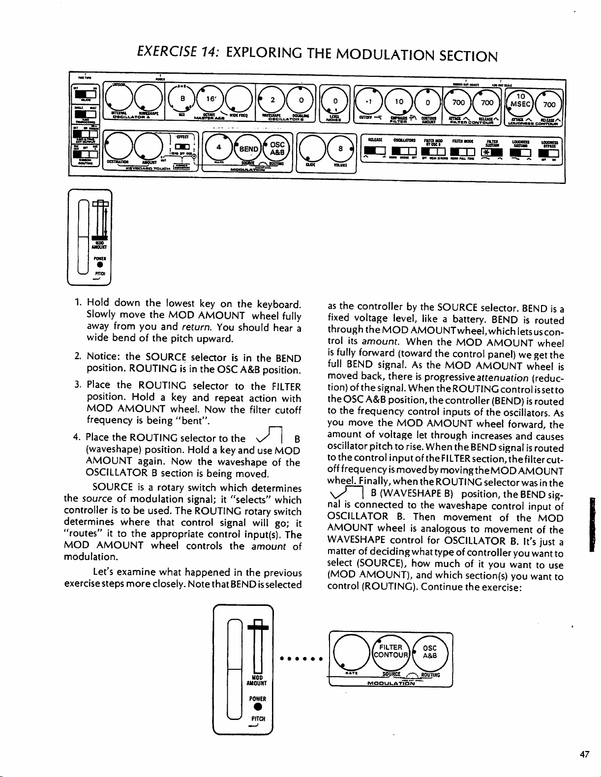
EXERCISE
rTh
ramt
1.
Hold
down
Slowly
away
from
wide
bend
2.
Notice:
position.
3.
Place
position.
MOD
frequency
4.
Place
the
(waveshape)
AMOUNT
OSCILLATOR B section
SOURCE
the
source
controller
determines
"routes"
MOD
modulation.
exercise
is
it
AMOUNT
Let's
steps
the
lowest
move
the
MOD
you
and
of
the
pitch
the
SOURCE
ROUTING
the
ROUTING
Hold a key
AMOUNT
is
wheel.
being
"bent".
ROUTING
position.
again.
is a rotary
of
modulation
to
be
where
to
the
examine
more
Now
used.
The
that
appropriate
wheel
what
closely.
14:
EXPLORING
key
on
the
keyboard.
AMOUNT
return.
is
You
upward.
selector
in
the
OSC
selector
and
repeat
Now
selector
Hold a key
switch
signal;
control
controls
happened
Note
to
the
waveshape
is
being
which
it
ROUTING
signal
control
that
wheel
should
is
in
A&B
to
the
action
the
filter
the
and
moved.
determines
"selects"
rotary
will
input(s).
the
amount
in
the
BEND
fully
hear
a
the
BEND
position.
FILTER
with
cutoff
\S
|
B
use
MOD
of
the
which
switch
go;
it
The
of
previous
is
selected
THE
MODULATION
tlffttf
^tfHIffTOC
«om
mom
en
as
the
controller
fixed
voltage
through
trol
is
full
moved
tion)
the
to
you
amount
oscillator
to
off
the
its
amount.
fully
forward
BEND
back,
of
the
OSC
A&B
the
frequency
move
of
pitch
the
control
frequency
wheeU-inally,
\S
nal
OSCILLATOR
AMOUNT
WAVESHAPE
matter
select
(MOD
control
I
B
is
connected
of
deciding
(SOURCE),
AMOUNT),
(ROUTING).
by
level,
MOD
AMOUNT
When
(toward
signal.
signal.
As
there
is
When
position,
control
the
MOD
voltage
to
rise.
input
of
is
moved
when
(WAVESHAPE
to
B.
Then
wheel
is
control
what
how
and
SECTION
ninao
aoa
mam
±
en
kmsim
mm
the
SOURCE
like a battery.
the
the
the
MOD
progressive
theROUTING
the
controller
inputs of
AMOUNT
let
through
When
theFILTER
by
movingtheMOD
the
ROUTING
B)
the
waveshape
movement
analogous
for
OSCILLATOR
type
much
which
Continue
selector.
BEND
wheel,
MOD
control
which
lets
AMOUNT
panel)
we
AMOUNT
attenuation
control
(BEND)
the
oscillators.
wheel
increases
the
BEND
section,
position,
to
of
controller
of
section(s)
the
forward,
and
signal
thefilter
AMOUNT
selector
the
BEND
control
of
the
movement
B.
you
it
you
want
you
exercise:
BEND
is
a
is
routed
uscon-
wheel
get
the
wheel
is
(reduc
issetto
is
routed
As
the
causes
is
routed
cut
was
in
the
sig
input
of
MOD
of
the
It's
just
a
want
to
to
use
want
to
47
Page 43

5.
Set
SOURCE
preceding
shown.
6.
Depress
contoured-pitch
7.
Place
FILTER
tone
color
FILTER
8.
Control
AMOUNT
9.
Place
position.
contoured
10.
Place
the
position.
LATOR B (only)
11.
Repeat
FILTER
controls.
SUSTAIN
and
ROUTING
page.
Set
and
hold
"siren"
the
ROUTING
position.
is
also
amount
the
Note
Play
is
contoured
being
wheel.
ROUTING
that
now.
ROUTING
Play.
Now
is
being
steps
5-10
CONTOUR
Try
both
switch.
controlsasshown
MOD
any
contoured.)
of
only
switch
the
and
AMOUNT
key.
You
should
effect.
selector
the
selector
WAVESHAPE
ATTACK
settings
to
the
same
key.
as
well
as pitch.
contour
the
to
contoured.
experiment
using
to
the
filter
(tone
the
and
of
the
^
wheel
OSC A&B
Note
j—i
of
with
on
as
hear
a
that
(The
MOD
FILTER
color)
is
'
B
OSCIL
the
RELEASE
FILTER
In
the
following
apparent
deals
12.
13.
that
much
with
repeating
Select
the
Explore
MOD
all
AMOUNT
exercise
of
the
patterns:
_]"!_
possible
wheel
steps,
MODULATION
"*rt
SOURCE
ROUTING
positions.
it
will
source
MOOUUATIOIM
..---.
setting.
settings
become
section
routTSc
and
When
SOURCE,
selector
is
controlled
amount
AMOUNT
AMOUNT
the
amount
MODULATION
Modulation
often a repeating
of
any
repeating
control.
"modulation
MODULATION
hold
circuitry
modulation
A
controller.
terns—waveshapes
often
restricted
control
moving
and
the
eight
Hz,
modulation
Hz.
Its
_f~[_
wave,
respectively)
the
FILTER
any
section(s)
may
be
contoured.
using
of
this
contour
wheel.
control
of
the
SECTION.
change.
modulation
RATE
controls
oscillator"
section.
whose
oscillator.
modulation
It
is a source
to
signals
modulations
like.
or
output
are
Vibrato
beats
per
oscillator
is
,and
CONTOUR
named
The
FILTER
in
FILTER
is
sampling
low
CONTOUR
is
(Note
the
FILTER
CONTOUR
usually
On
the
frequency,
that
Also
oscillator
of
like
any
frequency.
generally
like
vibrato,
rate,
for
second.
has a frequency
represented
S*\/
in
the
MODULATION
is
the
selected
by
the
ROUTING
speed
of
this
contour
controls.
controlled
that
section
by
the
CONTOUR
doesn't
as
used
The
the
MOD
affect
in
the
(END
defined
the
is
controlled
is
included
rate
is
one
repeating
oscillator—which
used
example
On
,
as a
change,
Multimoog,
or
the
is
is
controlled
which
That's
to
trills,
is
the
Multimoog,
span
by
(square
the
rate
by
the
RATE
speed
of
the
heart
of
the
sample-and-
by the
is
used
as
a
voltage
because
make
"wah-wah,"
around
the
and
pat
are
the
slow-
six
to
the
of
.3
to
30
symbols
triangle
section.
14.
Vary
the
RATE
the
modulation.
15.
Select
alternately
and
S&H
KBD
selector.
SOURCE
Repeat
setting.
EXERCISE)
If
you
recall
to
the
sound
of
the
voltage
section
series
normal
frequency
modulation
subaudio
modulation
will
input
effects
voltage
determined
modulation
sample-and-hold
camera. A camera
and
sample-and-hold
at a very
of
clicks
hearing
of
low
was
range.
normal
oscillator
range
for
oscillator
be
dramatic
of a VCO
from
The
steps
indeed
or
preceding
sample-and-hold
in a metronomic
by
the
oscillator).
works,
"holds"
a
fixed
"photographs"
control
exercise
to
control
the
s^\/
settings
steps
13
1,
you
with
and
began
controlled
frequency.
perceived
That
hearing,
produces
control
purposes.
as a sound
when
VCF.
You
exercise
So
instead
sound
or
it
was
waveshapes
source,
connected
have
heard
steps.
creates
fashion
RATE
control,
To
let's
"samples"
instant
(frequency
understand
make
(photographs)
in
time
(samples)
the
speed
of
,S&HAUTO,
the
SOURCE
14
for
each
by
listening
OSCILLATOR
low,
that
of a sound
was
below
sub-audio.
We
can't
but
its
B
only
a
in
the
The
in
the
use
the
effect
to a control
some
of
the
a
series
of
control
with a rate
of
the
how
the
an
analogy
(the
print).
to
a
motion
The
a
moving
r
48
Page 44

voltage
level.
taken,
the
mines
signal
and
When a sample
the
voltage
next
sample
how
often
"prints"
(holds)
of a moving
sensed
is
taken.
samples
at
that
The
are
taken.
a
fixed
voltage
instant
RATE
is
held
control
voltage
signal
is
until
deter
When
like
noise—a
produced.
does
sample
series
of
the
voltage
series
The
sample-and-hold
the
noise
random
voltage
signal
of
random
signal
internally,
steps.
sampled
voltage
of
See
is
random-
steps
will
be
the
Multimoog
and
produce
a
illustration:
RANDOM
FROM
NOISE.
In
the
case
of
modulation
same
triggering
section
be
useful
of
the
KEYBOARD
sound
This
orientation
enhance
mode
MOD-AMOUNT-wheel
oscillator
rate
as
it
generates
are
"synchronous"—happen
Now
that
and
have a feeling
to
read
SOURCE
also
you've
definitions
and
TOUCH
The
KEYBOARD
with
the
same
hand
section
of
carries
of
the
instrument
expressivity
operation
and
lets
PATTERN
SAMPLING
the
5&H
produces
new
samples.
explored
for
its
for
ROUTING
SECTION
TOUCH
that
the
"source-destination"
power
you
replace
and
use a single
-J1
AUTO
the
capabilities,
each
section
plays
a
in
performance.
the
mode,
"triggers"
(Sampling
together.)
the
at
the
and
MODULATION
it
might
specific
selectors.
lets
the
further
setting
(See
you
shape
keyboard.
step
to
One
left-hand-on-
hand
to play
appropriate
section
The
the
textures
use
of
destination
are
important
the
Multimoog—retaining
The
other
"two-hand"
When
TOUCH
section
Set
up
in
this
pages
of
the
manual).
MODULATION
of
the
MOD
which
the
AMOUNT
orientation
performance
mode
section
is
linked
the
provides
operation
the
following
of a synthesizer
EFFECT
is
set
to
to
the
and
REVIEW
section
synthesizer
wheel
of
the
MODULATION
features
expressive
simply the
switch
MOD,
KEYBOARD
begin
the
OF
FUNCTIONS
creates
and
many
is
capable.
the
source-
section
of
the
Multimoog.
capabilities.
most
expressive
to
date.
in
the
KEYBOARD
the
MODULATION
TOUCH
exercise:
section.
of
The
EXERCISE
UNISON
ram
ran
15:
EXPLORING
ocnvi
MASTin
ACD
^»
00©
i
wnsun
THE
mukoc
KEYBOARD
1.
Tune
OSCILLATOR A to
using
the
2.
Depress
AMOUNT
of
vibrato.
TOUCH
INTERVAL
and
hold a key.
wheel
control.
forward
SECTION
MC* . HUAS/
uouowncoMtuua
match
OSCILLATOR
Slowly
move
to
control
the
the
MOD
amount
B
49
Page 45
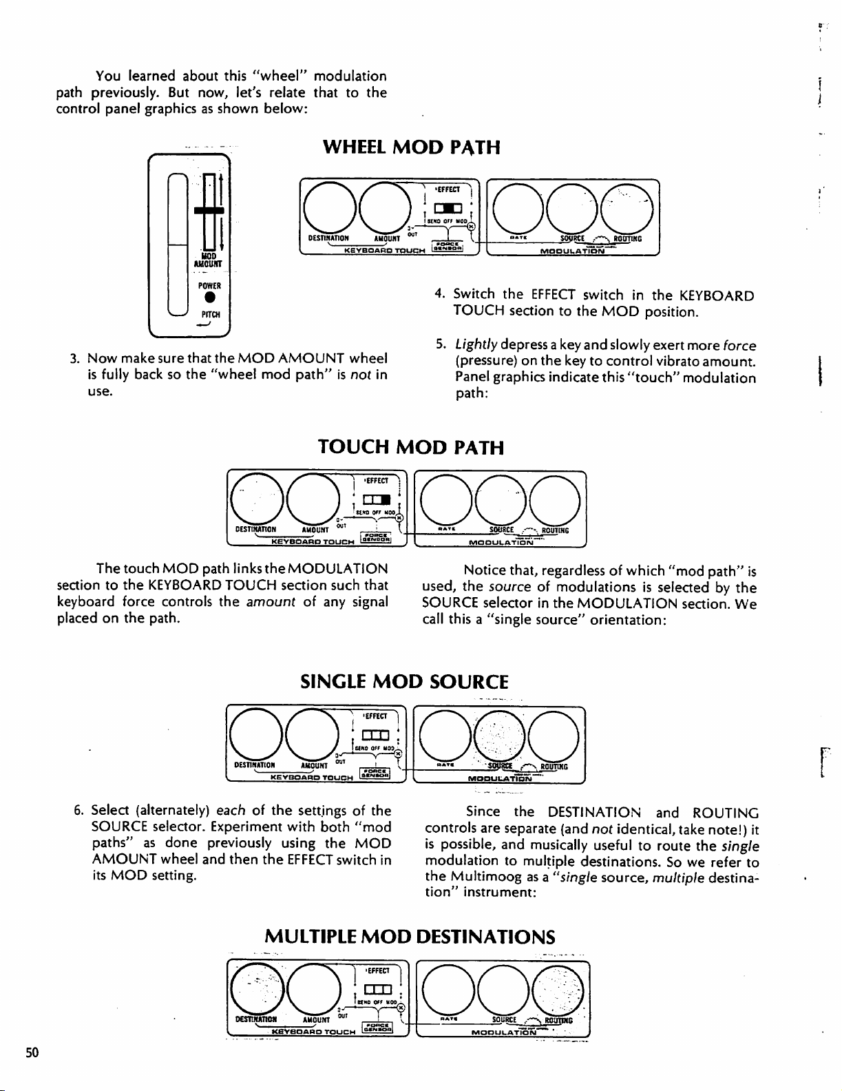
You
learned
path
previously.
control
panel
graphics
about
But
now,
as
this
"wheel"
let's
relate
shown
below:
modulation
that
to
the
3.
Now
is
use.
make
fully
back
sure
that
so
the
the
MOD
"wheel
mod
WHEEL
AMOUNT
path"
is
TOUCH
MOD
wheel
not
in
MOD
PATH
4.
Switch
TOUCH
5.
Lightly
(pressure)
Panel
path:
the
section
depress
on
graphics
PATH
EFFECT
the
switch
to
the
MOD
a
key
and
slowly
key
to
control
indicate
this
in
the
KEYBOARD
position.
exert
more
vibrato
"touch"
amount.
modulation
force
The
touch
section
keyboard
placed
to
the
force
on
the
6.
Select
SOURCE
paths"
(alternately)
as
AMOUNT
its
MOD
MOD
path
links
KEYBOARD
controls
path.
selector.
done
wheel
setting.
TOUCH
the
amount
each
Experiment
previously
and
then
the
MODULATION
section
of
any
such
signal
SINGLE
of
the
settings
with
using
the
EFFECT
MULTIPLE
of
both
"mod
the
MOD
switch
MOD
that
MOD
the
in
Notice
used,
the
SOURCE
call
this a "single
that,
regardless
source
selector
of
modulations
in
the
MODULATION
source"
orientation:
SOURCE
Since
controls
is
possible,
modulation
the
Multimoog
tion"
instrument:
the
DESTINATION
are
separate
and
musically
to
multiple
as a "single
(and
not
useful to
destinations.
DESTINATIONS
of
which
"mod
path"
is
selected
section.
and
ROUTING
identical,
source,
take
note!)
route
the
So
we
multiple
destina
is
by
the
We
it
single
refer
to
50
Page 46

7.
Experiment
DESTINATION
are
many
useful
control.
When
position,
the
the
with
the
various
and
ROUTING
combinations
EFFECT
KEYBOARD
switch
is
settings
controls.
of
in
TOUCH
of
the
There
touch/wheel
the
MOD
and
MODULATION
OFF,
the
KEYBOARD
(but
the
When
the
KEYBOARD
the
MODULATION
sections
MODULATION
EFFECT
switch
TOUCH
section,
are
linked.
TOUCH
section
section
section
is
in
is
the
BEND
works
as
shown
When
independent
EFFECT
can't
be
not
affected).
position
is
used,
the
of
below:
ma
8.
Play.
Vary
keyboard.
9.
Vary
(maximum)
may
10.
Select
Play.
(Confirm
one
11.
Try
different
graphics.
AMOUNT
be
set).
OSC A on
Now,
by
oscillator
all
of
AMOUNT
If
you
have
amount
Pitch
bend
only
using
and
the
of
force
bend
(upward)
control.
is
changed.
the
DESTINATION
OSCILLATOR
MIX
control
then
the
DESTINATION
settings.
only
one
exerted
is
heard.
Interval
(Exact
A
is
being
to
listen
other.)
settings.
Read
hand
to
spare
on
the
explanatory
of
intervals
OSCILLATOR A is
OSCILLATOR
the
(frequency)
When
control.
bent.
to
first
hear a pitch
to
bent.
A
effect
Use
the panel
when
which
Experiment
"synched"
playing
All
of
the
DESTINATION
except
DESTINATION
control
OSCILLATOR
change,
OSCILLATOR
We
do
tries
to
remain
manually
affects
with
sound.
the
synthesizer,
"SYNCH A TO
"synched"
B.
Also,
the
control
input
A
frequency
since
OSCILLATOR
B—and
OSCILLATOR
hear a "tearing"
in
synch
with
by
turning
the
frequency
various
INTERVAL
consider
settings
B."
(tied
control
of
signal
is
routed
OSCILLATOR
is
bent,
sound
B.
the
of
the
as
You
can
INTERVAL
only
OSCILLATOR
settings
following:
are
In
this
in
pitch)
coming
we
A
is
B
isn't
OSCILLATOR
get
the
to
self-
setting,
to
into
to
the
A
only.
won't
synched
being
same
control,
A.
vary
the
51
Page 47

12.
Bend
pitch
13.
Control
attached
panel.
actually
OPEN
MODULATION
the
KEYBOARD
are
used
musical
MOD
SYSTEM
The
Multimoog
simultaneously
nuance:
using
keyboard
vibrato
to
amount
the
MODULATION
AMOUNT
set
the
sensitivity
section of
jack
is
most
TOUCH
and
and
force
sensitivity.
using a foot
jack
wheel
for
procedure).
MODULATION
independently
may
of
the
pedal.
this
manual
powerful
pedal
on
the
be
used
(See
for
when
both
sections
to
create
rear
to
the
the
14.
Control
keyboard
15.
Control
AMOUNT
brightness
force
sensitivity.
modulation
wheel.
(END
Now
that
you've
TOUCH
it
might
about
DESTINATION
REVIEW
section
be
specific
and
have a feeling
useful
to
read
settings
controls.
OF
FUNCTIONS
and dynamics
amount
using
EXERCISE)
explored
some
of
the
SOURCE,
(See
appropriate
section
the
for
its
of
the
comments
EFFECT,
of
this
KEYBOARD
capabilities,
pages
manual.)
using
MOD
made
and
of
the
OSCILLATOR
OSCILLATOR B may
well
as a sound
OSCILLATOR B as a controller
"clangorous"
EXERCISE
OO00OIO0I0
Kitnti
1.
52
Hold
OSCILLATORS
(the
2.
Move
STRONG
in
3.
Return
position.
"+5."
Continue.
down
Oscillator
the
sound
FILTER
Play.
B
SECTION
be
source.
sounds.
16:
ansmn
FILTER
position.
texture.
Place
In
that
OSCILLATOR
m
any
key.
switch
section
MOD
Now
MOD
CONTOUR
FILTER
AS
used
as a controller
You
have
already
in
exercise
case,
the
sound
B
acrart
^»
wx*
tutnaua
is
in
is
the
BY
play
BY
section
nta
Notice
the
NORM
sound
OSC B switch
and
OSC B to
AMOUNT
source).
notice
is
CONTROLLER
as
used
5,
to
create
source
AS
BOTH
bouh
mriaun
that
control
contoured.
eaumnc
DouajKC
the
position
to
the
change
the
OFF
to
was
the
TONE).
OSCILLATOR
a
controller
SOUND
7SS7
4.
Place
position
5.
Place
that
dramatic
and
contoured.
FILTER
The
the
use
the
section
following
B
may
simultaneously:
SOURCE
FILTER
MOD
once
EMPHASIS
of
FILTER
when
filter
(END
(FILTER
sound
be
used
as
the
AND
again.
CONTROLLER
BY
OSC
Now
play
control to
MOD
the
EMPHASIS
cutoff
frequency
EXERCISE)
MODE
chart
sound
to
and
"0."
BY
control
switch
shows
source,
the
STRONG
note
Play.
Notice
OSC B is
is
set
is
to
that
and
effect.
most
high,
being
Page 48

The
WEAK
FILTER
output
the
B
cutoff
source,
more
of
sounds
FILTER
is
OFF
over
follow
ratio
sections.
placed
heard,
MOD
of
control
section
frequency.
its
complex
the
FILTER
you
When
in
used
only
position).
the
the
between
OFF
it
BY
OSCILLATOR
input
acts
as a controller,
own
signal
sound.
MOD
create.
you
TONE
mode
as a controller
But
entire
is
keyboard,
keyboard
Even
though
and
still
under
and
STRONG
OSC B switch
B
(DOUBLING
of
the
FILTER
When
make
the
the
OSCILLATOR
is
modulated
You
might
BY
OSC B switch
clangorous
(see
Exercise
(OSCILLATORS
to
maintain
the
to
maintain
OSCILLATOR B and
the
OSCILLATORS
OSCILLATOR
keyboard
positions
connect
section.
rapidly
modulating
by
experiment
sounds
5),
consistency
OSCILLATOR
the
B
control.
of
the
the
entire
included)
OSCILLATOR
B
is
the
itself,
creating
with
any
using
OSCILLATOR
switch
of
same
frequency
switch
section
to
filter
sound
a
with
use
of
the
the
B
to
timbre
B
must
FILTER
is
is
not
PITCH
an
important
signal
input
pitch
NOISE
TONE
element
center
bump.
way
depressing
center
down
release of
"center,"
ribbon
the
bending
instruments—don't
Ribbon
The
PITCH
that
of
the
of
the
section,
mode.
protected
of
the
This
to
feel
bump.
with a similar
the
or
is a most
performer
associated
ribbon
performance
is
conneaed
oscillators.
oscillators
or
The
ribbon
causes
the
no
"center"
the
ribbon
Oscillator
to
The
only;
the
FILTER
PITCH
with
plastic-coated
is a dead
bending
of
and
movement
ribbon
the
at
any
original
important
to
achieve
with
ignore
the
left
controller.
to
the
PITCH
it
has
section,
ribbon
band,
of
the
pitch.
moving
pitch
point,
pitch
instantly.
development
the
all
its
use!
of
the
keyboard
It
generates
(frequency)
ribbon
no
bends
effect
even
when
is a resistance
mesh.
marked
pitch,
and
provides
Pitch
is
away
from
may
be
bent
on
the
ribbon.
pitch
is
returned
The
that
subtlety
of
solo-line
is
a
control
the
on
the
in
In
the
with
a
a
bent
by
the
up
or
On
to
PITCH
allows
pitch
musical
EXERCISE
1.
Depress
2.
Place
the
(left
hand)
ribbon.
17:
and
hold
any key
"pad"
on
the
directly
over
PITCH
with
end
of
the
bump
RIBBON
your
your
middle
on
right
hand.
finger
the
PITCH
AND
RIBBON
5.
Bend
above
move
6.
"Tap
either
The
tact;7e
and
the
feedback—you
spatial
violinist's
technique
Continue:
ROUTING
toward
(or
toward
out"
side of
Multimoog's
feedback—like
is
the
note by
below)
trills
the
the
center
by
hitting
the
center
can
string.
Development
critical
for
SWITCH
depressing
center
PITCH
feel
the
believable
bump,
bump.
on a specific
bump.
ribbon
it.
It
also
trombonist's
of
pitchbending
the
finger
and
then
interval
gives
you
gives
visual
slide,
or
solo
lines.
3.
Press
down
alternately
pitch
away
4.
Now,
ribbon;
without
how
much
ribbon
slightly
above
run
your
notice
causing
and
from
the
finger
that
the
force
and
cause a pitch
with
your
below
note.
lightly
the
bump
pitch
to
must
be
used
bend.
left
hand;
the
bump
over
the
can
be
"found"
bend.
Learn
to
engage
slide
to
bend
PITCH
exactly
the
7.
Perform
will
8.
Place
Bend.
9.
Place
A
position.
be
a
bend).
the
(There
the
RIBBON
bent.
wide
bend
upward.
RIBBON
will
ROUTING
be
no
ROUTING
Bend.
Now,
only
(Both
oscillators
switch
bend.)
switch
OSCILLATOR
to
to
the
OFF.
OSC
A
will
Page 49

The
usefulness
oscillator
wondering
ROUTING.
simply
Multimoog
control
bend
is
fairly
apparent,
why
there
Wouldn't
didn't
the
use
the
is
an
open
other
synthesizers.
oscillators
of
of
being
able
but
is
an
OFF
position
the
result
be
PITCH
ribbon?
system
synthesizer
Suppose
an
external
synthesizer
to
bend a single
perhaps
the
Not
you
you
are
for
RIBBON
same
if
you
exactly.
The
that
can
wished
to
but
not
those
position,
makes
KBD
information,
manual.)
of
the
Multimoog?
for
internal
In
addition,
the
RIBBON
output
on
the
see
the
routing
the
output
rear
OPEN
So,
we
include
purposes
KBD & TRIG
available
of
the
Multimoog.
SYSTEM
only.
EXT
(or
section
an
OFF
OUTPUT
not)
at
the
For
more
of
this
TRIGGER
A
action
CONTOUR
signal
generated
Trigger",
of
triggers
SOURCES
trigger
is a signal
the
FILTER
sections
sound
by
the
short
for
that
acts
to
CONTOUR
of
the
Multimoog. A trigger
The
particular
Multimoog
"switch
VOLTAGE + |
is
refered
trigger".
i
KEY
I
DEPRESSED
start
and
end
and
LOUDNESS
type
of
to
as
an
The
S-Trig
SWITCH
the
like a switch;
depressed
produced.
signal
"S-
and
illustration:
acts
TRIGGER
an
An
ends
when
KEY
whenever
S-Trigger,
S-Trig
all
keys
RELEASED
a
key
on
or
drop
begins
when a key
are
released.
the
keyboard
to
zero
volts,
is
depressed,
See
below
for
is
is
an
A
trigger
to
initiate
below
and
depicts
is
used
to
start
the
contour
terminate
the
relationship
musical
sounds.
between
TRIGGER/CONTROL
CONTROL
VOLTAGE
I
I
I
S-TRIG
I
+
1
I
KEY
DEPRESSED
generators
The
diagram
a
trigger
FROM
and
a
CONTOUR
possible
generator:
VOLTAGE
GENERATOR
control
RELATIONSHIP
KEY
signal
I
RELEASED
produced
by a contour
54
Page 50

EXERCISE
18:
SINGLE/MULTIPLE
TRIGGERING
KEYBOARD
PRIORITY
OOOQOI0QO
a*Asa
XJ
oas
am_^^^—u
OCSItUTtOH
1.
Play
(legato)
Notice
Alternate
effects.
is
to
SINGLE.
2.
Move
"+2".
and
staccato
CONTOUR
3.
Move
the 100
occurs
As
this
Multiple
rapid
passages
is
interesting
triggering
^^"^^L
(UtOUKT
the
keyboard
and
the
difference
techniques
Note
that
the
CONTOUR
Notice
the
is
that
technique
AMOUNT
FILTER
msec
position.
more
quickly
exercise
triggering
to
insure
to
note
different
BUT
detached
?
alternately
MOOULATION
with
(staccato)
in
sound
for
phrasing
the
KBD
TRIGGERING
AMOUNT
the
difference
is
is
reduced.
CONTOUR
The
now.
indicates,
can
that
notes
that
MoogT"-style
from
some
control
between
less
exaggerated
RELEASE
"head"
musical
be
useful
will
not
other
wmiuri
eousu«c
OttCILLATOR
O0
connected
technique.
response.
and
accent
Switch
back
to
legato
as
control
on
use
(END
during
be
"multiple"
to
the
note
of single
EXERCISE)
very
"lost".
multiple
It
triggering
being
triggering
several
is
do
to
is
trigger
coincide,
sensing a pitch
is
most
effective
contoured.
requires
controls.
that,
unlike
on
the
the
expressivity
used.
4.
Select
organs
keyboard
Continue
the
TRIGGERING
triggering.
5.
Play
as
generated
less
of
keyboard
schemes.
since
Making
some
But
the
and
of
of
the
exercise:
MULTIPLE
switch to
before.
to
coincide
technique.
Triggers
new
triggers
change.
when
the
FILTER
good
experimentation
important
some
synthesizers,
the
Multimoog
music
when
use
thing
can
single
position
provide
Note
that a new
with a new
and
new
pitches
are
generated
section
of
to
remember
what
is
single
with
you
contribute
triggering
of
the
KBD
multiple
trigger
pitch
literally
is
regard
always
by
S&H
is
section.
that
AUTO
The
other
the
S&H
AUTO
In
this
mode, a series
is
controlled
UQ
OSCILLATOR
rant
mat
TRIGGERING
source
in
A
of
triggers
mode
rate
by
the
on
the
Multimoog
of
the
MODULATION
of
triggers
RATE
EXERCISE
is
generated
control.
19:
OQPP0ODO
Like
any
S&H
oncnuAToap
O0
trigger,
generators
note
that a S&H
time
taken
AUTO
oioc
TRIGGERING
muna
Place
position.
and
ATTACK
CONTOUR
occupies
and
these
silence
hold
triggers
on
the
Multimoog.
AUTO
by a given sample;
■~n
the
mm
SOURCE
Notice
will
and
RELEASE
section.
only
clock.
activate
trigger
selector
that
at
any
be
equal
times
The
half
of
the
It
see
period
60th
might
lasts
only
exercise
to
the
RATE
(given
in
the
trigger
contour
be
useful
half
below:
S&H
setting
near-instant
LOUDNESS
"on"
of
the
sample
to
of
the
AUTO
sound
time
Page 51

The
S&H
KBD
position
does
not
produce
generators
independent
exercise:
2.
Place
the
is
not
self-triggering.
3.
Hold
down
keyboard
The
MODULATION
control
the
contour
keyboard.
triggers!
may
be
of
the
SOURCE
any
is
triggering
signals.
You
generators
of
the
SOURCE
In
this
mode,
triggered
rate
selector
key.
section
will
by
the
of
sampling.
to
S&H
Release,
the
hear
hold
contour
continues
sound
are
triggered
selector
the
contour
keyboard,
Continue
KBD.
Sound
again.
generators.
only
The
to
create
when
by
the
(END
External
Multimoog
OUTPUT
section
of
EXERCISE
1.
If
you're
incredible
by
returning
discovering
This
TOUR.
rotary
priate
of
For a review
switch
pages
this
manual.
triggers
via
either
on
the
rear
this
manual).
20:
BOLSTERING
still
wad
to
how
concludes
on
the
of
the
REVIEW
EXERCISE)
may
be
routed
the
S-TRIC
panel
INPUT
(see
OPEN
THE
here
after
wading
of
information,
an
earlier
much
part
you've
through
bolster
of
the
learned!
(REST)
our
of
each
control,
front
panel,
OF
GUIDED
SYNTHESIZER
slide-switch,
refer
to
FUNCTIONS
to
the
or
S-TRIG
SYSTEM
EGO
this
your
ego
manual
the
and
and
appro
section
56
Page 52

An
"open
system"
can
communicate
with
other
open
devices.
This
section
system
of
the
manual
communication
synthesizers
communication
audio,
internally
make
hear
to
an
sounds.
called
Electronic
must be
(amp
when
are
"interfacing
two
or
With
made,
are
very
(phaser,
instrument
the
audio
explains
how
between
and
Moog
with
control,
(see
An
electronic
sounds—it
electrical
amplifier
"audio"
and
you
more
many
further
signals,
Signals
instruments
connected
speaker).
connect
devices
instruments,
possibilities
limited.
wah-wah
and
signal
and
GUIDED
musical
makes
and
that
signals—they
systems."
Even
amp,
produced
electrical
so
we
speaker
are
translated
have
to
the
To
use a bit
your
Multimoog
so
they
after
if
you
pedal,
you
the
inputs
the
accessories.
external
trigger signals
SYNTHESIZER
instrument
signals.
connect
to
an
audio
That
work
the
of
"interfacing
fuzz)
are
still
by
the
the
translate
into
become
audio
output
input
of
technical
to
means
together
audio
connection
put
sound
between
dealing
instrument.
and
outputs
Multimoog
You
will
synthesizer
produced
TOUR
doesn't
We
can't
instrument
signals
sounds
of a monitor
an
connecting
into
are
audible.
which
jargon,
amp,
you
properly.
is
systems"
modifiers
the
with only
on
and
external
understand
gear
through
electronic
ment,
to
trigger
control
and
signals
designer
the
That's
panel
make
trigger
INPUTS
Multimoog
better
by
the
section).
The
interfacing
the
synthesizer
make
sound.
signals—to
signals—to
other
aspects
are
created
provides
synthesizer,
what
of
the
most
signals
allow
the
rear
Multimoog
synthesizer's
instruments.
the
the
output
Multimoog
of
the
available
these
from
panel
devices
"open
if
you
allow
such
as
system"
know
how
function
potential
systems
Like
generates
But
the
synthesizer
turn
sounds
dynamically
of
sound.
internally
paths
instrument
Multimoog's
the
These
for
them
and
input
are
to
signals
outside
for
is
greater
any
electronic
audio
signals
on
alter
trigger
by
the
synthesizer.
to
leave
is
an
"open
sockets
all
about.
The
audio,
the
outside
to
be
world.
two-way
other
the
music-making
than
most
instru
in
order
also
produces
and
off;
and
pitch,
timbre,
and
control
If
the
(and
enter)
system."
on
the
rear
OUTPUTS
control,
world.
fed
and
The
into
the
An
open
Multimoog
be
triggered;
other
Multimoog
instrument,
produce,
growth
exception
3/16"
two-prong
dual
function—they
output.
can
instruments.
but
modify,
of
your
Rear
of
stereo
Cinch-Jones
The
system
control
produce
as
not
an
musical
panel
MODULATION
jacks.
and
sound
You
only a self-contained
expandable
trigger,
jacks
Trigger
connectors.
act
primary
function
MULTIMOOG
synthesizer
be
controlled;
and
modify
might
ideas
as
start
thinking
system
and
control
requires.
are
}A"
and
signal
either
(as
of
sound—as
mono,
GLIDE,
connections
Many
an
input
named
REAR
like
trigger
sound
devices
on
from
of
musical
with
which
require
sockets
and/or
the
CONNECTOR
the
and
the
that
the
the
are
are
an
rear
panel)
output
available
musical
a
to
types
system
Once
signals
will
of
The
sockets
at
use.
short
"Getting
"slave"
of
signals.
The
synthesizer
you
work
become
PANEL
such
sockets
following
for
the
rear
After
It
one
Multimoog
key
to
understand
within
apparent.
will
be
pages
audio,
panel,
the
individual
Together"
creative
lies
the
describe
trigger,
with
to
freedom
in
knowing
how
audio,
Multimoog,
discussed
and
some
descriptions,
section
another
control,
first.
the
input
and
control
suggestions
that
using
using
your
their
signals
for
there
is
shows
instrument.
and
external
how
all
three
an
open
trigger
uses
57
Page 53

^00
no
ran
«-(W/0fF
AUDIO
act
Koouunm
C0HT8CL-'
ntnt
SIGNALS
oscub
J-TWS
>-«»>
INPUTS-
TOUCH
'
EFFECTS
MOD
nn
o
me
TURE
LO/HI
audio
monitoring system
low
a
P.A.
HI
AUDIO
direct
output
pedal,
effects.
used
output
Filter
stronger)
changing
the"formants"
For
region,
of
the
Filter
output
the
particularly
since
control
between
AUDIO
The
/AUD/O
(sound)
level
(-10
or
guitar
is a high
connection
Like
an
may
be
fuzz,
or
In
particular,
to
modify
could
to
create
in
timbre.
example,
arou
nd
playable
to
create
to
have a formant
imitation
suitable
the
Multimoog
signals
instruments.
OUTPUTS
output
to
dBm)
output
amplifier
level
to
electric
modified
other
sound
Moog900
audio
be
passed
"peaks"
the
harmonic
The
present
the
bassoon
500
Hz
range
a
peak
of
the
for
used
OUTPUTS
of
create
that
output
many
guitar,
output.
through
(like
907
creates
in
many
that
is
of
the
at
500
at
bassoon.
use
also
for
are
used
to
route
the
Multimoog
sound.
suitable
has
power
the
using a phaser,
modifier
Series
equalization
has a formant,
present
instrument.
Hz
would
that
with
externalizes
effective
LO
AUDIO
for
connection
its
own
preamplifier.
(+12
dBm)
amplifiers.
Multimoog's
to
create
modules
For
instance,
a
Moog
spectrum,
conditions
acoustic
instruments.
throughout
Use
cause
frequency,
The
Multimoog
modular
equipment,
communication
to
capable
audio
wah-wah
special
may
audio
907
Fixed
but
much
radically
similar
or
resonant
most
of
the
the
sound
enhancing
trigger
the
a
is
a
to
of
be
to
907
is
and
AUDIO
purpose
instruments
You
may
output
recorders,
Multimoog.
it
is
adequate
instruments
drive;
as
with
level
pickups,
the
AUDIO
amps
used
AUDIO
FILTER
path.
connect
INPUT,
Multimoog.
doesn't
AUDIO
oscillators
the
guitarist.
Multimoog
of
the
remove
(place
internal
to
ON)
INPUT
The
AUDIO
is
through
input
of
and
The
input
impedance
dynamic
provide
for
this
When
INPUT,
section
It's
important
an
instrument
only
produce
INPUT
to
will
guitarist.
the
OSCILLATORS
voltage
so
the
INPUT
to
allow
feeding
the
any
external
electric
guitars,
microphones
AUDIO
for
the
output
(100
mV
RMS
microphones
preamplification
INPUT
purpose.
an
may
a
separate
external
it
appears
and
follows
to
an audio
The
external
control
connection
make
them
And
the
not
be
So,
for
basic
oscillators
switch
controlled
guitar
may
is a single
Multimoog
audio
INPUT
level
input
is
100K
be
necessary.
preamp
audio
at
the
remember
like
the
signal
instrument—the
and
trigger
"follow"
contour
triggered
use
from
to
amp
be
heard:
<fgi
function
the
sound
for
signal,
organs,
into
this
is
fixed
of
many
required
Ohms).
or
guitars
before
the
introduction
output
signal
is
audio
normal
that
guitar to
is
provided
jack.
of
other
modification.
such
as
pianos,
jack
on
in
sensitivity;
electronic
for
In
some
cases,
with
Many
guitar
that
can
fed
into
input
of
audio
signal
when
the
AUDIO
to
guitar—
signals.
won't
the
generators
by
the
of
the
the
audio
OFF);
(place
wmaigtl
luoiittiii
A
simple
control
tune
played
in
articulations
AUDIO
INPUT
signal
and
bypass
BYPASS
switch
tape
low-
you
the
path
the
Its
the
the
full
to
be
the
the
the
the
by
58
oq
Q@eoc
*>*
^.^5,«
OQS!
AUDIO
ttttfltf*
POKER
_>«««£«
MOOULATIOA
MHtlUft
obciliatco
DOUMJXC
a
O0
INPUT
SOUND
cotoff
—^
utnass
-pA
PII.TOO
mm
a»
CHART
eoiitoB«
UKXMT
w
oo
tnta
"S
ttuN
Page 54

As
with
any
controls
SOUND
sound
EMPHASIS
should
be
CHARTS
chart,
experiment
controls;
Multimoog
placed
section).
vary
RATE
sound
fully
counterclockwise
When
with
you
the
and
chart,
try
the
CUTOFF
MOD
AMOUNT;
blank
(see
above
and
select
SOURCE.
section
instrument.
trigger signals
S&H
KBD
These
to
modify
In
as
are
means
this
case,
are
being
the
MODULATION
of
controlling
the
timbre
no
internal
used.
of
sound
section
the
FILTER
the
external
sources
or
LO
AUDIO
HI
WDW
S-TB6
OFF
ON
KBD & TRIG
EXT
OUTPUT
S-TRIG
input)
switch
ON + RIBBON
Its
primary
when
hold
OUTPUT
The
S-TRIG
only
when
on
the
The
S-TRIG
purpose
one
is
produced
(S&H
AUTO)
front
position.
US
B8SOR
RIBBON
OUTPUT
the
panel
OUTPUT
is
in
is
KBD
AND
is
switched
is a dual function
to
externalize
by the
keyboard
the
Multimoog.
TRIGGER
KBD
CUBE
FT^
"
KOOUUmOH
,
LON/OFF
OWTROL-'
functional
TRIG
EXT
to
a
trigger
or
RUM
I
(as
output
OUTPUT
either
ON
device.
signal
sample
This
and
output
SIGNALS
OK
Ml
J-1BS
tNPUTS
routes
or
or
Moog
contour
that
used
articulate
a
key
might
be
triggered
shown:
AUDIO
TOUCH
HOD
ACCESSORY
Errccrs
signals
911
Envelope
(envelope)
accepts
to
route a trigger
the
on
the
be
connected
pokir
'
that
can
Generator,
generators
S-triggers.
sound
of
Multimoog.
to
by
the
keyboard
tana
trigger
When
to
another
that
Multimoog
modules
921
Oscillator,
of
another
the
S-TRIG
synthesizer,
synthesizer
For
example,
of
by
Multimoog
B
so
Multimoog
FIRE
JURE
such
as
the
or
the
synthesizer
OUTPUT
we
can
is
depressing
A
that
both
will
A,
as
S-TRIG
When
will
also
(Multimoog B will
connected,
input—it
The
to
tell
information;
and/or
The
acts as
signals.
OUTPUT
Multimoog
be
triggered
because
cannot
ouput a trigger.)
primary
the
outside
when a key
the
rate
of
S-TRIG
an
input
And
external
will
trigger
not
the
function
world
the
sample
OUTPUT
for
trigger
the
OUTPUT
S-TRIG
OUTPUT
MULTIMOOG
A
is
triggered
through
trigger
S-TRIG
its
S-TRIG INPUT.
Multimoog A as
INPUT
TO
S-TRIG
STANDARD
'
FEMALE-MALE
A
Multimoog
acts
only
as
an
B
CINCH-JONES
FILTER
internally-produced
trigger
over
triggering.
of
the
S-TRIG
important
is
depressed
and
is
dual
externally-produced
applied
LOUDNESS
OUTPUT
internal
and
released,
is
timing
hold.
function;
it
also
trigger
to
the
S-TRIG
CONTOUR
and
applied
be
when
no
triggers
internal
special
like
INPUT
CABLE
MULTIMOOG
TRIGGERING
S-TRIG
INPUT
B
CONTOUR
routed
both
to
triggered
no
external
work
effect
control
to
the
keyboard
That
means,
the
S-TRIG
regardless
internal
triggers
trigger
is
normally.
triggers
are
is
created,
voltages
sections
present,
do.
of
the
trigger
S-TRIG
OUTPUT,
of
present
If
would.
OUTPUT
and
S&H
when
an
the
internal
are
present.
all
internally-produced
When
both
simultaneously,
that
is,
triggers
an
internal
Multimoog,
An
AUTO
external
Multimoog
as
an
external
has
priority
internal
trigger
is
will
conditions—even
Naturally,
external
when
and
no
do
not
"add"
trigger
is
already
59
Page 55

present
trigger
converse.
(e.g.,
externally
key
depressed),
will
not
application
be
of
another
discernible,
and
the
The
following
input/output
capacity
diagram
of
illustrates
the
S-TRIG
the
dual
OUTPUT
plug:
S-TRIG
CABLE
DETAIL:
NARROW
WIDE
Each
Multimoog
Multimoog A will
Multimoog
S-TRIG
for
trigger
B
will
trigger
OUTPUT
ads
signals.
will
trigger
Multimoog
as
both
OUTPUT
SOCKET
SOCKET
trigger
TO
S-TRIG
OUTPUT 1 FEMALE-FEMALE
itself
normally.
Multimoog
A
because
an
input
and
an
S-TRIG
CINCH-JONES
(COVER
B,
and
each
output
NOT
OUTPUT
NOrS-STANDARD
S3O2-CCT
SHOWN)
Any
the
Multimoog
Addition
switch
contact
TRIGGERING
CABLE
MULTIMOOG
simple
using
of a capacitor
closure
S-TRIG
OUTPUT
B
switch
can
the
S-TRIG
is
required
as
shown:
be
modified
OUTPUT
to
trigger
as
an
input.
to
"debounce"
S-TRIG
The
accepts
LOUDNESS
sections
would.
has
absolutely
S&H
trigger
moog
But
the
external
ignored.
60
an
of
An
priority
AUTO
is
will
when
S-TRIG
(Internal
SWITCH
SWITCH
TO
OPEN
CLOSED
INPUT
S-TRIG
external
the
external
no
mode.
applied
be
the
INPUT
triggers
INPUT
trigger
CONTOUR
Multimoog
trigger
over
effect
This
to
triggered
Multimoog
is
and
fed
keyboard
when
means
the
S-TRIG
even
is
removed
applied
keyboard
APPLY
The
switch
acts
only
signal
FILTER
as
an
into
the
triggering,
the
Multimoog
that
when
INPUT,
if
no
in
the
S&H
from
there
triggers
TRIGGER
1>iF.20V
CAPACITOR
will
as
an
input.
that
triggers
CONTOUR
internal
S-TRIG
but has
is
an
external
the
key
is
depressed.
AUTO
the
circuit
are
completely
are
also
INPUT
trigger
trigger
INPUT
in
Multi
mode,
ignored
It
the
the
and
a
Multimoog
in
trigger
S&H
When
no
"add"
depressed
trigger
the
INPUT
with
useful
can
TO
S-TRIG
CINCH
JONES
S302-CCT
CABLE
SOCKET
when
the
S&H
AUTO
is
present,
AUTO
both
external
special
effect
like
control
closed.
mode.)
(and
mode)
keyboard
and
is
created;
voltages
(internal
to
the
S-TRIG
S&H
AUTO
and
Obviously
an
"S-trigger,"
type
devise
any
mode,
the
keyboard
the
or
of
trigger
kind
of
OUT
the
internal
trigger),
INPUT
S-TRIG
"switch
input,
simple
PLUG
SMALL
SOCKET
LARGE
SOCKET
Naturally,
Multimoog
do.
will
triggers
are
when
is
triggers
work
triggers
that
is,
triggers
For
example,
application
not
be
discernible.
from
ignored
INPUT
trigger."
because
switch
entirely.
is
This
the
that
no
external
not
in
the
normally.
are
present,
do
not
if a key
of
another
the
is
I
n
S-TRIG
compatible
is a very
performer
will
close
to
Page 56

trigger
required;
produced.
triggered,
OUTPUT.
and
switch
INPUT
of a Cinch-Jones
the
"switch
Multimoog
internally
closures,
capacitor.
theMultimoog.
when
To
show
touch a coin
You're
you've
triggered
closure—without
functions
plug.
inserted
Cinch-Jones
closure/'
speaks.
"debounced"
the
switch
No
power
the
switch
how
easily
to
both
now
using
the
Multimoog
use
the
same
way,
When
plug
or
S-trigger
Since
to
does
not
supply
is
closed a trigger
the
prongs
this
plug
of
circuitry.
but
the
two
are
touched
is
the
clean
require
or
circuitry
Multimoog
of
as a
by
requires
wires
can
the
S-TRIG
trigger
making
The
S-TRIC
insertion
attached
together,
produced
S-TRIC
up
the
and
INPUT
dirty
switch
addition
is
is
be
input
a
to
a
the
is
of
a
The
Moog
trigger
the
be
very
families
S-TRIG
the
may
produce
Moog
Oscillator,
the
1121
must
compatible
The
S-TRIC
versatile.
(RTL,
INPUT
Multimoog
also
be used
V-triggers
960, 961,
Moog
non-Moog
cates
wiring
1121
Footswitch
Multimoog.
be
replaced
with
the
INPUT
It
is
compatible
TTL,
CMOS,
is
+2
volts;
to
be
triggered.
with
modules
(voltage
962,
Sequencer
Sonic
Six
synthesizers!
procedure:
can
be
modified
The
existing
with
5-772/C
acts
only
DTL).
signals
triggers),
output
a
Cinch-Jones
INPUT
as
an
with
standard
The
threshold
less
than
The
S-TRIC
or
synthesizers
plug
plug
socket.
input,
but
of
2
volts
cause
INPUT
such
as
Complement,
synthesizer,
The
following
and
even
graphic
to
on
to
is
logic
the
that
the
921
...
indi
TIP
FROM
V-TRIG
OUTPUT
JACK
The
above
does
not
transform
shown
when a V-trigger
above,
Many
the
synthesizers
GROUND
SWITCHCRAFT
V."
S250
MONO
PHONE
cable
acts
V-triggers
cable
will
is
"off."
produce
V-TRIG
V-TRIG
PLUG
VOLTAGE
only
as a connector;
into
provide
an
a
V-trigger
TO
TO
GROUND
V-TRIG
"OFF"
S-TRIG
"ON"
S-triggers.
S-trigger
(voltage
S-TRIG
S-TRIC
SHIELDED
S-TRIG
V-TRIG
it
As
only
CONNECTOR
CABLE
"OFF1
ON"
HIGH
(ABOVE
LOW
trigger)
the
Multimoog
"gate")
following
Cinch-Jones
+2V)
(BELOW
when a key
output
circuitry
plug
CONVERSION
SMALL
CINCH
JONES
P302-CCT
CABLE
PLUG
+2V)
is
depressed.
using
the
of
such
between
in
the
LARGE
If
V-trigger
an
instrument,
the
previous
CIRCUIT
PRONG
TO
S-TRIG
OF
PRONG
you
(sometimes
phone
INPUT
MULTIMOOG
wish
to
trigger
called
insert
the
plug
and
diagram.
TIP
The
circuit
trigger.
Moog
from
switch,
(This
Music;
The
S-TRIC
external
and
Controller,
inverts
V-Trig
to
S-Trig
part
#74-221).
INPUT
sources
Moog
The
S-TRIC
such
Accessories
IN
4148
DIODE
a
V-trigger
accepts
as
INPUT
and
malces
cable
is
available
timing
information
another keyboard,
such
as
the
expands
the
it
an
S-
from
a
1130
Drum
musical
potential
1130
the
sound
impossible
necessary
synthesizer.
of
the
instrument.
Drum
S-TRIG
Controller
INPUT
with
sticking
on
the
keyboard
part
of
allows
LARGE
PRONG
JONES
PLUG
For
instance,
to trigger
the
Multimoog
the
drummer
techniques
Trigger
any
totally
input/output
"open
use
to
that
would
of
the
using
articulate
be
is
a
system"
Page 57

LOMJDIO
BMWO
V.
S-TK
.;
OUTPUTS-
CONTROL
SIGNALS
an
an
ram
0
ma
nmi
KEYBOARD
The
KBD
function
the
panel
only
counterclockwise
control
oscillators
keyboard
the
keyboard
devices.
interfere
KBD
the
ribbon,
EXT
panel
even
OCTAVE,
on
affects
the
zero
ascending
increment
62
jack.
KBD & TRIG
is
in
either
The
KBD
when
The
keyboard
signal
and
control
KBD
OUTPUT
to
The
with
OUTPUT
keyboard,
according
OUTPUT
controls
those
WIDE
the
rear
keyboard
KBD
OUTPUT
When
volts
of
OUTPUT
OUTPUT
It
can
function
EXT
the
ON,
OUTPUT
its
associated
"click"
that
normally
the
cutoff
signal
jack.
control
use
of
normal
provides
or
both
to
switch
that
panel.
the
is
produced
half-step
+1/12
on
have
no
affect
FREQ,
However,
responses,
signal.
lowest
volt
(keyboard
as
OUTPUT
or
ON + RIBBON
jack
can
output)
an
output
switch
function
attenuator
position.
of
the
Multimoog
controls
frequency
is
available
You
can
external
the
KBD
internal
the
control
the
keyboard
the
setting
the
front
effect
pitch
DOUBLING,
since
GLIDE
key
is
at
the
on
the
to
the
of
for
usetheMultimoog's
(voltage-controlled)
OUTPUT
keyboard
signal
of
the
panel.
on
the
internally,
the
settings
depressed,
KBD
keyboard
signal
is a dual
only
when
on
the
front
position.
as
an
input
is
in
the
fully
generates
the
pitch
the
filter.
external
does
control.
from
and
the
KBD & TRIG
Other
KBD
OUTPUT,
such
and
FINE
GLIDE
will
a
signal
OUTPUT;
adds
level
(nominally
a
of
the
This
use
at
not
The
only
PITCH
front
as
TUNE
control
affect
of
each
an
one
volt
per
octave).
yields
keyboard
calibration,
provided
"outside"
some
KBD
of a Moog
the
play
oscillator
parallel
keyboard.
KBD
oscillator
play
keyboard!
an
tones
precise
diatonic
control
an
attenuator
(above
Once
the
using
interesting
OUTPUT
921
in
can
921
Voltage
"track"
the
unison
is
tuned
intervals
Suppose
OUTPUT
controlled
higher
externally
when
as
you
If
you
controlled
half
Although
modules
keyboard
concept
monophonic
Multimoog
regardless
several
may
be
using the
should
be
(single
produces
of
how
keys
are
Internally,
(twelve
of
the
jack).
keyboard
the
KBD
musical
be
connected
Controlled
keyboard
with
its
at
an
will
be
produced
we
invert,
signal
upside
with
play
attenuate
oscillator
steps
are
any
number
controlled
KBD
understood.
voice)
only
many
depressed
precise
tones
oscillators.
with a voltage
control
OUTPUT,
results.
For
to
Oscillator
of
the
oscillators.
interval
to
when
or
electrically
down.
this
inverted
lower
on
(lessen)
would
played
on
of
voltage
from
OUTPUT,
The
synthesizer
one
keys are
depressed.
on
the
calibration
to
the
octave)
For
external
span
±10%
is
signal
you
the
the
is
brought
can
produce
instance,
the
control
Multimoog
If
the
the
oscillators,
you
An
signal
the
input
to
make
and
external
play
the
turn
the
external
would
Multimoog's
signal
by
half
play
quarter
the
keyboard.
controlled
the
Multimoog's
an
important
keyboard
control
Multimoog,
of
any
like
the
signal,
When
the
r
Page 58

lowest
signal.
than
and
But,
may
produce
independent
used
external
make
polyphonic
fully
largest
information
Multimoog
its
clockwise
control
the
controls
cutoff
Multimoog
signal
keyboard
OSCILLATORS
external
(but
frequency).
you
keyboard
source—such
keyboard
and
INPUT
add
means
which
when
keyboard
board
keyboard
OUTPUT
oscillators
the top
key
determines
A
monophonic
one
tone
oscillator
the
oscillators
if
the
keyboard
follow
parallel
might
is
the
single
chords,
voices).
to
control
manipulation
the
The
compatible
modular
The
associated
signal
internal
both
frequency
behaves
signal
will
When
can
control
of
filter
could
and
to
the
you
key
you
switching
control.
of
signal
is
note
several
keyboard
like
an
organ.
KBD
OUTPUT
with
systems.
to
the
outside
is
being
depressed.
KBD
OUTPUT
attenuator
to
the
"click"
fed
into
keyboard
the
pitch
of
the
controls
signal.
continue
the
easily
nothing.
exactly
For
switch
will
no
KBD
switch
to
as
the
the
Polymoog.
be
controlled
FILTER
INPUT;
internal
would
constantly
last
struck
from
The
the
Polymoog
in
the
used
as
of
the
Multimoog
of
the
Polymoog
monophonic,
So
the
signal.
to
an
keyboard
the
the
single
instrument
(the
be
tuned
keyboard
but
the
external
of
the
KBD
of
the
helps
other
keyboard
may
Minimoog
to
produce
all
the
control
not
polyphony
KBD
OUTPUT
oscillators,
OUTPUT
Multimoog
make
the
synthesizers
It
conveys
world—which
functions
(pot)
position.
KBD
Then
of
both
filter,
as
though
instance,
to
the
longer
control
OUTPUT
from
overriding
highest
Of
but
on
the
Multimoog
control
will
Multimoog
input.
as
an
input
is
turned
OUTPUTjack
and
(Note
DRONE
control
fully
In
this
the
external
oscillators
the
keyboard
that
the
it
were
the
if
you
setting,
the
the
filter
is
used
as
normal
Multimoog
external
note
played
course,
using
these
have
the
the
control
control
signal.
to
worry
Multimoog
to
signal
will
keyboard
from
simply
replace
when
The
pitch
always
in
control
have
more
has
three),
a
chord.
oscillators
signal
and
(several
might
be
but
no
signal
will
become
Multimoog
and
the
important
key
on
the
RIBBON
panel
the
signal
the
left
ribbon
attenuator
RIBBON
RIBBON
KBD
front
panel
the
keyboard
signal
Attenuation
GLIDE
when
counter
case, a
replaces
signal
and
the
of
the
external
internal
place
the
the
oscillators,
cutoff
an
input,
control
on
the
oscillators
OSC
A&B
inputs
That
about
(it
adds)
Polymoog
the
key
the
the
KBD
of
the
agree
with
this
case.
GLIDE
if
the
GLIDE
theGUDE
glide
on
(The
amount
the
rotary
MODULATION
jack.
It
MODULATION
output,
by
the
signals
selector.
may
be
We'll
review
the
subject
routing.
The
modulation
MODULATION
remains
The
have a spare
hold
patterns,
You
to
control
MODULATION
plug
as
OUTPUT
The
RIBBON
control.
created
of
the
may
be
associated
ROUTING
OUTPUT
FORCE
The
KBD
control.
that
appears
of
ON/OFF
The
GLIDE
switch
on
control
jack
The
Moog
or
off
of
GLIDE
MODULATION
acts
as
it
can
externalize
SOURCE
from
any
Several
accomplished
these
of
MODULATION
Moog
on
under
1121
hand
can
the
shown:
OUTPUT
The
RIBBON
by
depressing
keyboard.
scaled
with
switch
jack
signal.
is
OUTPUT
The
signal
for
external
the
RIBBON
has
OUTPUT
FORCE
always
this
signal
OUTPUT
The
amount
determines
at
the
KBD
must
be
CONTROL
jack
is
functional
the
front
panel
is
near
VOLUME
is
meaningless.)
1121
Footswitch
by
inserting
glide
both an
section
selector.
source
simple
simpler
1121
or
off
jack.
control
can
to
etc.
on
rewire
amount
jack.
its
plug
always
remains
control).
is a dual
function
input
(control)
whatever
As
an
input,
directly
switching
using
the
uses
section
Footswitch
by
inserting
(The
amount
of
theMOD
be
very
handy
turn
vibrato,
and
off.
any
volume
of
modulation
Remember
not
subject
always
the
PITCH
from
no
is
not
of
force
the
FORCE
achieved
only
switched
is
set
may
be
into
the
under
and
signals.
signal
it
to
the
or
attenuation
MODULATION
first
before
(control)
may
be
its
of
AMOUNT
when
shakes,
pedal
to
use a 3/16"
to
front
provides
ribbon
the
use
with
OUTPUT.
effect
subject
exerted
size
of
at
PITCH
the
The
on
the
to
on
(D.C.)
OUTPUT.
externally.
when
the
OFF.
(Also,
to
"0,"
use
of
used
to
turn
GLIDE
3/16"
an
routes
jack.
control
of
stereo
output
is
for
As
an
provided
control
ROUTING
tasks
jack.
taking
up
signal
used
to
turn
plug
into
the
modulation
wheel).
y.ou
don't
sample
(orjustapot)
and
using
the
stereo
TIP
(MOD
OUT)
SWITCHCRAFT
«"
STEREO
EXTERNAL
RING
(MOD
RETURN)
#S-260
PHONE
PLUG
MODULATION
CONTROL
SHIELDED
STEREO
CABLE
POT
(IN
PEDAL)
10KTO100K
AUDIO TAPER
63
Page 59

When
MODULATION
MOD
modulation.
AMOUNT
forward
used
over
MOD
AMOUNT
pedal
effects.
completely
will
Obviously,
have a span
effects.
Similarly,
the
pedal
jack,
wheel
When
(toward
the
the
the
control
widest
span
wheel
cover a restricted
if
back
(no
modulation),
of
"zero"
you
is
inserted
it
will
act
in
to
control
MOD
AMOUNT
panel),
of
modulation
is
only
slightly
span
the
MOD
and
could
AMOUNT
then
allow
set
the
into
tandem
the
the
of
with
amount
wheel
pedal
effects.
forward,
modulation
wheel
the
pedal
no
modulation
pedal
and
the
the
of
is
fully
can
be
If
the
the
is
will
play
the
wheel.
the
wheel,
movements
movements
A
practical
pedal
to
restrict
so
vibrato
of
the
are
easier
musical
the span
could
MOD
to
modulations.
In
the
previous
acts
as a variable
the
sensitivity
producing
instead,
of
vibrato.
as
shown:
example
resistor
the
MOD
A
fixed
application
of
be
controlled
AMOUNT
control-
used
to
AMOUNT
resistor
would
the
MOD
for
the
pot
attenuate
could
be
to
AMOUNT
with
larger
wheel.
Larger
subtlety
in
the pedal
(reduce)
wheel
when
be
used
set
of
This
arrangement
could
be
switched
in
or
SWITCHED
«"
STEREO
Now
let's
look
input/output
First
let's
is
selected
available
MODULATION
is
controlled
rate
(when
Now
MODULATION
to
the
ROUTING
capabilities
review the
by
externally
output
the
SOURCE
at
jack;
by
the
MOD
(3)
appropriate)
let's
look
jack:
(1)
selector;
FIXED
The
could
out:
PLUG
at
the
of
rules:
EXT.
value
be
made
actual
the
MODULATION
(1)
The
selector;
the
tip
contact
The
level
of
the
AMOUNT
is
set
by
the
at
the
input
The
input
signal
(2)
Therefore
MOD.
of
the
resistor
so
that
EXT.
control
(2)
wheel;
RATE
MOD.
signal
jack.
output
This
of
output
rules
goes
its
signal
signal
the
stereo
signal
(4)
The
knob.
for
the
directly
level
is
not
AMOUNT
may
be
seleaed
ATTENUATOR
to
it
AMOUNT
SHIELD
(NO
CONNECTION)
L
is
affected
the
MODULATION
from
Multimoog,
that
Connection
TION
Multimoog
-0
appropriate
any
The
allows
jacks
220K
RESISTOR
suit
your
taste.
ATTENUATOR
ATTEN
,O
vVA-
O
FULL
SWITCH
by
the
MOD
AMOUNT
contact
jack;
external
etc.).
diagram
Multimoog
is
made
for
(4)
This
source
below
A
to
between
(Multimoog
B
shows
input
wheel;
feeding
ring
(Moog
indicates
modulate
respective
A
shows
wiring):
220K
OR
SELECT
AS
DESIRED
(3)
The
signals
input
911, 921,
wiring
into
can
be
another
procedure
ring
Multimoog
MODULA
output
wiring;
is
the
fed
B.
(MOD
OUT)
(MOD
IN)
MULTIMOOG
modulate
both
MODULATION
64
SIMPLE
A
In
the
itself,
MODULATION
TIP
example
above,
because
jacks
JACK
TIP
neither
the
self-feeding
are
opened
Multimoog
switches
when a plug
TO
MODULATION
¥,»"
STEREO
will
on
is
PLUGS
inserted.
itself—as
jumper
If
you
well
wire
to
JACK
want
as
Multimoog
the
previous
CONNECTION
Multimoog
B—add
wiring
(MOD
TIP
MULTIMOOG
A
to
the
setup:
OUT)
SWITCH
(MOD
modulate
following
IN)
B
Page 60

MULTIMOOG
SELF-MODULATION
JUMPER
to
and
*"
STEREO
It
is
possible
from
SIMULTANEOUS
STEREO
TO
to
route
the
Multimoog
PLUG
MOD
JACK
modulation
simultaneously
INPUT
PLUG
signals
&
RING
OUTPUT
\
JUMPER
both
and
FROM
independently
synthesizer:
OF
TIP
TO
RING
TERMINAL
from a modular
MODULATION
MULTIMOOG
INPUT
(EXAMPLE:
SIGNALS
MULTIMOOG
OUTPUT
(EXAMPLE:
SYNTHESIZER
FROM
SYNTHESIZER
911
ENVELOPE
system
MODULATION
ANOTHER
or
another
MODULATION
TO
ANOTHER
921
OSCILLATOR)
GEN.)
The
MODULATION
powerful,
communication
FILTER
signals
the
FILTER
since
with the
INPUT
The
FILTER
capable
FILTER
INPUT
of
section.
it
provides
outside
INPUT
controlling
A
control
acts
as
RELATIONSHIP
CONTROL
^00
10
MKM
HI
WON)
L
S-TOG
-
OUTPUTS
-
jack
simultaneous
acts
the
an
"unseen
BETWEEN
no
—I
is
particularly
two-way
world;
only
signal
its
presence
as
an
input
cutoff
frequency
fed
into
hand"
EXTERNAL
SIGNAL
cunt
ukuutkw
t.ON/OFFCOIITIKM.''
for
the
that
nn»
*■
is
of
oscus
an
important
concept.
electrically
one
might
following
control
AND
j-tioc
WPUTS-
MKM
advance
manipulates
do
manually
depicts
and
the
analogy
control
by
MANUAL
TOUCH
MOO
UtESSOU
EFFECTS
FO*Et
in
the
open
system
internal
control
on
the
front
between
hand:
FILTER
CONTROL
synthesizer
elements
panel.
FILTER
as
The
INPUT
FRONT
PANEL
65
Page 61

If
zero
volts
is
fed
change
voltage
frequency,
knob. A negative
lowers
movement
of
one
section.
create
of
the
applied
the
of
one
volt
at
octave
In
practice,
this
change
cutoff
like
frequency
to
the
FILTER
clockwise
voltage
cutoff
frequency,
the
CUTOFF
the
FILTER
in
the
cutoff
only
because
into
the
FILTER
is
caused.
INPUT
movement
applied
knob.
INPUT
raises
of
to
the
like
counterclockwise
Nominally,
will
cause a change
frequency
about
.95
volts
the
input
is
designed
INPUT,
A
positive
the
cutoff
the
CUTOFF
FILTER
of
INPUT
a
change
the
FILTER
is
required
to
no
of
to
be
slightly
amplify
jikely
with a simple pot
internaPcontrol
Because
additive,
1120
FILTER
over-sensitive.
incoming
require
Signals
attenuat/on
fed
signals
external
you
could
Pedal
Control
CONTOUR.
This
prevents
signals;
the
sensitive
(lessening)
requiring
into
and
no
the
FILTER
to
control
internal
use a Moog
Source
in
your
having
input
will
of
the
power
supply.
INPUT
the
FILTER
control
signals
Accessory
conjunction
to
more
signal
add
to
section.
are
like
the
with
the
OSC
acts
the
signal
hand"
RELATIONSHIP
A&B
The
only
frequency
fed
that
INPUT
OSC
A&B
INPUT
as
an
input
for
(pitch)
into
the
OSC
electrically
(oscillators
signals
of
A&B
capable
both
INPUT
manipulates
BETWEEN
CONTROL
^00
10
AUDIO
HI
AUDIO I S-IRIG
-OUTPUTS
KBO
FORCE
-J
control
of
oscillators.
acts as
internal
EXTERNAL
SIGNAL
GUDf
MODULATION
l-ON/OFFCONTROLJ
input)
controlling
A
control
an
"unseen
control
AND
FIUE8
OSC
US
I
elements
panel.
ment
selector
as
The
best
of
the
is
in
one
WIDE
the
illustrates:
MANUAL
OSCILLATORS
CONTROL
S-TKS
INPUTS-
A&B
INPUT
AUDIO
TOUCH
FRONT
MOO
EFFECTS
PANEL
might
do
manually
analogy
to
manual
FREQ
knob
rightmost
position.
OSCILLATOR
m
nc
ACCESSORY
POWER
on
the
control
when
the
The
CONTROL
control
is
move
OCTAVE
following
HUE
TIKE
I f zero
change
voltage
clockwise
negative
counterc/odcw/se
knob.
Nominally,
INPUT
frequency
volts
is
input
is
prevents
sensitive
(lessening)
power
66
volts
is
of
oscillators
applied
movement
voltage
to
applied
movement
a
change
will
cause a change
of
the
oscillators.
required
designed
your
input
of
supply.
to
to
having
will
the
signal
fed
into
the
OSC
pitch
is
caused. A positive
the
input
of
the
WIDE
to
the
input
of
of
one
volt
of
one
In
practice,
create
to
more
this
change
be
slightly
amplify
likely
with a simple
over-sensitive.
incoming
require
A&B
INPUT,
raises
pitch,
FREQ
lowers
the
at
knob.
pitch,
WIDE
the
OSC
octave
only
about
FREQ
A&B
in
because
signals;
attenuation
pot
requiring
no
like
A
like
the
.95
the
This
the
no
Signals
internal
quency.
additive,
1130
Drum
keyboard.
TOUCH
Allows
path
of
MODULATION
the
EFFECT
fed
control
Because
you
could
Controller
MOD
input
the
KEYBOARD
section
switch
into
the
OSC
signals
external
to
control
and
internal
use a Moog
accessory
in
conjunction
EFFECTS
of
external
signal).
on
front
signal
TOUCH
Functional
panel
A&B
INPUT
add
oscillator
controls
such
with
into
the
section
is
in
(in
lieu
only
MOD
position.
to
fre
are
as
the
the
MOD
of
when
Page 62

The
open
system
provide
making
trigger
are
interfacing."
powerful
once
you
signals
It's
very
can
important
dumb—from a point
They
INPUTS
ways
of
realize
do
for
to
understand
must
OPEN
expanding
what
you.
SYSTEM—GETTING
and
OUTPUTS
audio,
that
of
view
be
told
explicitly
can
your
music-
control,
and
want
like
"I
play
both
have
synthesizers
of
"systems
what
you
requirements
Example
IT
TOGETHER
to
happen.
want
from
to
go
given:
You
to
slave a
my
keyboard."
from
the
for
general
each
may
begin
with a general
second
Multimoog
But
to
the
specific
class
of
to
mine
at
some
point,
interfacing
signal
involved.
idea
and
you
AUDIO
Multimoogs."
must
each
TRIGGER
when
played."
from
articulation
Master
Multimoog.
REQUIREMENTS
GENERAL:
SPECIFIC:
be
transduced.
ACTION:
Multimoog
"I
want
Audio
Connect
to
amp.
REQUIREMENTS
GENERAL:
the
SPECIFIC:
the
Master
ACTION:
Multimoog
"I
want
keyboard
Trigger
to
the
of
both.
Connect
to
to
hear
signal
from
the
AUDIO
to
hear
of
the
Master
signals
Slave
Multimoog
the
S-TRIG
the
S-TRIG
the
sound
each
the
sound
of
both
Multimoog
OUTPUT
of
both
Multimoog
must
be
supplied
to
provide
OUTPUT
INPUT
S-TRIG
of
the
OUTPUT
of
Slave
of
is
the
CONTROL
GENERAL:
instruments
Multimoog."
SPECIFIC:
Multimoogs
signal
Multimoog
Multimoogs:
of
the
ACTION:
Multimoog.
The
connection
REQUIREMENTS
"I
to
follow
The
must
be
Master
Connect
to
the
following
for a Master-Slave
S-TRIG
want
the
OSCILLATOR
controlled
the
pitch
keyboard
of
section
by
the
Multimoog.
KBD
OUTPUT
OSC
INPUT
diagram
of
of
shows
interface
INPUT
of
both
the
Master
of
both
keyboard
theMaster
the
Slave
the
basic
for
two
D
The
Master
FRONT
PANEL
KEYBOARD
MASTER
Multimoog
triggers
S~\
AL
AUDIO
OUTPUT
TO
AMP
Q
and'controls
both
itself
and
the
FRONT
PANEL
KEYBOARD
SLAVE
Slave
Multimoog.
AUDIO
OUTPUT
TO
AMP
67
Page 63

Even
connections,
successful
SYSTEM
provides
though
further
interface.
section
an
First,
you
unsealed
QQQeQQaSEQSSS
you
have
thought
know
is
from
reading
that
version
made
the
required
the
the
KBD
OUTPUT
of
the
basic
for
a
OPEN
Master
MASTER
SLAVE
Multimoog
to
cause
keyboard
charts
keyboard
the
Slave
accurately.
below
for a tuning/scaling
must
omuains
■nmrn
ton
h«m
«• v mi*
signal.
Multimoog
Let's
It
will
have
to
follow
think
in
terms
procedure:
ruomod
mm
wot
rau
tow
uin.1T
mm
susn»
u»«inicai.t
womb
inns
mm
to
be
scaled
the
Master
of
the
sound
iooo«s
sswi
OO0QO
First
of
all,
let's
level
to
the
other,
instruments
pitch
"zero."
zero
volts,
volts
Multimoog.
open
where
tuning:
1.
Depress
of a band
represented
Why?
the
and
will
This
strings
the
of
frets
the
Multimoog
signal.
2.
Place
BYPASS
sound
of
just
together.
by a keyboard
When
output
not
the
at
influence
is
rather
two
guitars
(scaling)
lowest
to
set
of
each
each
continuously
(for
tuning,
tune
one
Multimoog's
as
we
would
We
should
signal
Master
its
KBD
like
are
key
each
keyboard
OUTPUT
the
pitch
resorting
when
on
on
to
you're
each.
the
keyboard
"zero
Multimoog
for
leave
MOD
pitch
tune
all
the
tune
at
the
voltage
will
of
the
to
tuning
To
accomplish
volt"
keyboard
ON
to
of
signal
is
be
zero
Slave
the
not
sure
of
each
hear
the
tuning.
tOEUt
OIOLUtOtS
AMOUNT
pitch
fully
3.
Use
the
each
Multimoog
Now
level.
toward
FINE
Master
At
OSCILLATORS
keyboard
accidental
transpose
producing
keyboard).
notice
increasingly
is
because
version
the
Master's
won't
touching
its
pitch.
parallel
If
you
that
the
diverges
the
of
the
KBD
RUIUMD
note*
0*'
«[M
StKMC
ROM
you)
TUNE
control
to
match
and
Slave
this
point
you
switch
of
the
affect
its
of
the
{Useful
intervals
play
the
Master
Slave
will
follow
as
you
Slave
is
being
Master
keyboard
OUTPUT.
RUMBOOt
in
controlled
mitt
UUOKS
sucr««
KOTiu
r
on
the
rear
their
pitch.
are
tuned
might
Slave
pitch.
Slave
some
at
the
to
want
to
to
DRONE
Otherwise,
keyboard
applications,
touch
of
keyboard,
pitch
generally,
go
up
the
keyboard.
by
an
signal,
Let's
available
scale
it:
lOUtWQS
on
panel
the
place
the
you
unsealed
nrus
T|
a>
of
same
the
so
its
any
might
like
Slave
may
but
This
from
68
Page 64

4.
Check
keyboard,
5.
Play
attenuator
Master
moogs
always
When
OUTPUT
the
OSCA&BINPUToftheSlave,to
diatonic
tuning
highest
and
by
is
you
signal
scale.
by
if
OK
key
for
KBD
Slave
listening
near
A-440.
scale,
from
the
playing
go
on
agree
you
Master
lowest
on.
If
not,
Master
to
keyboard
OUTPUT
in
pitch.
OSCILLATOR
stretch
to
fit
key
on
Master
repeat
on
or
the
create
steps
and
adjust
Master
Tune
Multi-
B,
which
shrink
the
sensitivity
the
familiar
1-3,
until
KBD
of
Play!
Notice
Slave
can
be
wheels.
paths,
can
mance
the
plug,
appropriate
section of
Complete
can
be
The
connection
be
made
using
the
front
panel
If
you
and
socket
portion
this
that
quite
created.
and broken
KBD & TRIG
of
the
would
on
manual.
settings
different.
voices,
between
Master
like
to
the
rear
of
the
for
the
Try
MOD
with
separate
the
Master
instantly
EXT
during
OUTPUT
instrument.
review
panel
REVIEW
what
does,
OF
Master
AMOUNT
and
modifier
and
Slave
perfor
switch
each
refer
FUNCTIONS
on
jack,
to
the
Multimoog
69
Page 65

70
r
Page 66

review
of
functions
This
terminology
described
below.
jack
priate
31
32
33
34
section
and
socket
Multimoog
in
A
description
functions
numbers
«y
oa
OQ
'
»»""-*^'w«
I I I
I
KHYHOAWO
16
of
the
on
the
is
assumed;
functions
the
order
can
be
on
17
indicated
of
how
gotten
the
following
coo
1
TQt
18
manual
Multimoog
are
any
by
turning
m»grm«AS»
tells
how
functions
don't
numbered
by
individual
pages.
MOOLICATIOW
19 20
start
here
and
the
diagrams
control
to
the
oqppoqoqpo
|
or
appro
o»ciu*tbp ■ J V «—' J t
21
each
—
if
22
knob
what
you
23
selector,
it
does.
can't
10
«iutbb
rrnrmniD
a
aurn
24
25 26 27 28
switch,
Knowledge
speak
on
"synthesizerese!"
11
laeon
o"
"g»tl
«im
mt
12
filtbo
«w
nu
jack,
plug,
of
13
contour , towCMan
mm
to«
^^»
BBCT1
-*
14
SSIOI
—+•
*■>•
29
15
coNrroun
RKB
en
oi
oa
30
35
36
rani
37 38
UMtSIO
HI
MOW
39
40
S-TBC
OUTPUTS
KBO
41
TOOK
42
43
44
45
.UD
OBE
HOOOUTKHI
l-ON/OFFC0NTROL->
FUCI
46
OSCJUB
47
S-TDG
WPUTS
48
tUOW
49
TOUCH
KOO
50
MSESOtT
51
CD
52
□□
53
O
fIRE
TUIIC
71
Page 67

MULTIMOOG™
CONTROL
PANEL
The
oscillator
pitched
1
(only)
Perfect
VAL
steps.
2
OSCILLATOR
position
form;
is
mixed
WAVESHAPE
marked
the
waveform
toward
narrow
rectangular
to
Sawtooth,
of
available.
control
the
the
3
audio
.UNISON.
INTERVAL
Provides
relative
Fifth
relative
control
is
WAVESHAPE
Provides
marked
as
the
control
with a narrow
control
"5/'
the
sawtooth
"lose"
sawtooth
output
FILTER
MIX
truncates.
is
produced;
"10,"
rectangular
waveform
the
square,
and
This
allows
a
of
the
control
Provides
oscillators
provides
clockwise
OSCILLATOR
sent
arbitrary,
A&B.
the
output
position
B
mixes
of
in
units
section
signals.
INTERVAL
OSCILLATOR
continuous
to
OSCILLATOR
to
calibrated
(A)
continuous
A;
calibrated
"0"
provides
is
moved
rectangular
is
rectangular
Between
the
square
wave.
is
sound
continuously
change
a
Full
only.
the
at
variable
variable
instrument
settings.
continuous
counterclockwise
of
"B"
Intermediate
two
from
"0"
OSCILLATOR
is
the primary
WAVESHAPE
A
tuning
of
B.
Tuning
OSCILLATOR
with
marks
waveshape
in
arbitrary
the
sawtooth
clockwise,
waveform.
moved
toward
waveform
"5"
and
as
the
control
waveform
The
narrowness
limited,
making
any
WAVESHAPE
rectangular,
rectangular
variable
of
the
harmonic
that
is
independent
mix
OSCILLATOR
provides
the
positions
oscillators.
to
"10."
source
MIX
OSCILLATOR
span
B.
The
INTER
indicating
control
units.
wave
this
sawtooth
As
the
position
widens
"6"
a
square
is
moved
narrows
of
it
impossible
setting.
and a mixture
waveforms
WAVESHAPE
spectrum
of
the
audio
position
A
only.
output
repre
Calibration
A&B
of
OCTAVE ^-WIDEFREQ
MASTER
is
half-
of
The
the
and
on
to
a
this
are
of
of
"A"
Full
of
is
A&B
4
OCTAVE
A
±
increments
keyboard
position
order
oscillators
positions
TUNE
control
of
the
OCTAVE
all
pitch
the
FULL
companied
the
cutoff
(normal)
a
half-octave
The
OCTAVE
expands
eight
octaves.
5
WIDEFREQ
Provides
approximately
OCTAVE
The
WIDE
center
approximately
FREQ
control
(32'-2')
FREQ
control
selector
FREQ
control
tuned
tuning
using
the
WIDE
FREQ
to
allow
control
WAVESHAPE
OSCILLATOR
Selects
to
FILTER
registers.
to
tune
both
from
32'
to
2'
stops,
as
footage
activates
the
provide
over
an
eight
of
OCTAVE
on
the
is
control
to
When
position,
by a concomitant
frequency
position,
the
per
each
selector
the playable
reference.
adjacent
continuous
octave
is
accomplished
rear
panel.
internally
maintain
the
a
pitch
of
cutoff
pitch
is a performance
span
DOUBLING
oscillators
with
WIDE
span.
The
arranged
consistent
FILTER
change
the
of
change
filter.
frequency
change
of
the
continuous-sweep
eight
octaves,
selector
FREQ
point
settings
is
set
intervals
span.
FINE
is
placed
control
marked
the
8'
do
not
interfere
on
the
is
operable
to
its
rightmost
tunes
both
remain
The
WIDE
TUNE
control
control
may
instantaneous
is
set
to
activate
operable
to
the
rightmost
is
calibrated
"0"
places
range.
Settings
with
OCTAVE
selector;
only
when
position.
oscillators
the
same
FREQ
control
on
the
be
"preset"
transposition
WIDE
FREQ).
B
in
octave
middle
The
FREQ
tuning
Fine
CUTOFF
MODE
one
of
In
of a full
keyboard
C
on
the
rightmost
control
of
tuning
using
to
track
tone
switch
octave
one
octave
the
is
changed
in
both
in
all
the
FINE
control
the
color
in
is
in
is
ac
in
NORM
by
octave.
control
which
to a full
tuning
only
over
when
the
position.
in
octaves;
the
Multimoog
on
the
any
of
the footage
the
the
The
the
in
WIDE
WIDE
OCTAVE
WIDE
proportionately-
over
the
entire
is
fine-tuned
rear
panel.
to
any
(when
The
pitch
level
OCTAVE
72
Page 68

6
WAVESHAPE
(B)
FILTER
Provides
OSCILLATOR
position
as
mixed
and
square
on
narrow
marked
the
control
with a narrow
the
sawtooth
waveform
toward
rectangular
rectangular
to
"lose"
Sawtooth,
of
sawtooth
available.
control
the
the
7
waveform
primary
The
doubling;
doubling
provides
allows
output
FILTER
DOUBLING
Provides
OSCILLATOR
"0"
center
from
at
doubling
continuous
B;
calibrated
"0"
provides
is
moved
truncates.
is
produced;
"10,"
the
square
wave.
waveform
the
sound
square,
This
control
either
variable
and
variable
continuously
a
change
of
the
instrument
settings.
a
continuous
one
or
position
that
point
the
two-octave
at
the
waveshape
in
arbitrary
a
sawtooth
clockwise,
rectangular
waveform
Between
as
the
waveform
The
narrowness
is
limited,
at
making
any
WAVESHAPE
rectangular,
rectangular
variable
of
the
harmonic
that
is
mix
two
octaves
B
pitch
for
doubling
provides
a
dead band
clockwise
interval;
octave.
control
units.
waveform;
this
sawtooth
"5"
and
control
is
narrows
it
impossible
setting.
and a mixture
waveforms
WAVESHAPE
spectrum
independent
of a square
lower
than
effects.
with
to
"+5"
provides
from
"0"
to
of
The
variable-height
frequency,
is
above
widens
"6"
a
moved
to a
of
this
are
9
of
of
of
FILTER
the
control
calibration
frequency,
the
no
frequency
selector.
synchronized
fundamental
"-5"
10
The
FILTER
with a 24dB/octave
the
cutoff
CUTOFF
CUTOFF
Provides
the
cutoff
is
FILTER
becomes
manual
frequency
placed
The
in
MODE
a
indicates
with
"0" a point
set
by
FILTER
with
frequency
EMPHASIS
section
resonant
is a lowpass
peak
at
attenuation
frequency.
EMPHASIS
FILTER
control
of
the
the
oscillatory
switch
wide-range
octave
OSCILLATOR
in
the
to
increments
very
the
oscillatory
oscillators
or
at a harmonic.
CONTOUR
-r'N
AMOUNT
of
the
nominal
lowpass
frequency
filter.
mode
TONE,
near
the
B
in
the
at
the
filter
with
the
cutoff
slope
setting
When
the
by
switching
the
CUTOFF
control.
of
fundamental
8'
mode
The
the
cutoff
OCTAVE
may
be
oscillators'
NOISE
The
NOISE
dorandom)
purposes.
8
LEVEL
Introduces
control
is
calibration
pseudo-random
pink
noise;
available
control
is
used
mixes
audio
removed
the
for
has
as a sample
noise
output
from
OSCILLATORS
section
signal
turned
is
arbitrary.
generator
this
is
sample
no
effect
as
an audio
of
the
the
sound
provides
used
for
noise
as
clockwise
The
which
also
filtered
and
hold
on
the
and
hold
signal
oscillators.
chain
switch.
a
pink
noise
both
audio
an
audio
to a maximum
noise
internally
purposes.
noise
source
signal.
relative
The
by
selecting
and
control
source
generator
outputs
essentially
and
The
when
The
LEVEL
control
to
the
oscillators
may
"OFF"
(pseu
as
the
of
10;
is
a
made
LEVEL
noise
fixed
be
on
"Emphasizes"
frequency
resonant
is
reached
The
will
not
performance.
position
on
the
separate
to
the
into
the
setting.
11
amount
the
FILTER
FILTER
mark = one
the
filter.
band
AMOUNT
"positive"
frequency
of
the
peak
at
at
position
EMPHASIS
be
placed
Maximum
may
be
rear
of
the
FILTER
TONE
position
oscillatory
CONTOUR
A
reversible
and
polarity
CONTOUR
section;
octave
The
"0"
where
no
contouring
is
moved
contour
of
the
the
filter
by
that
frequency.
"10";
control
into
oscillation
adjusted
instrument.
MODE
switch
to
unequivocally
mode
AMOUNT
attenuator
of a control
calibration
of
sweep
center
clockwise
is
allowed
filter,
producing
area
around
increasing
Maximum
calibration
is
restricted
accidentally
emphasis
by
("Q")
the
user
The
Multimoog
which
the
the
height
is
so
that
at
through
may
be
place
regardless
to
the
is
of
position
can
of
the
EMPHASIS
that
controls
voltage
control
in
the
cutoff
routed
input
octaves.
Each
frequency
provides
occur.
to
As
CONTOUR
toward
control
a
rising-and-falling
the
cutoff
of
a
emphasis
arbitrary.
the
filter
during
the
"10"
a
port
has
a
switched
the
filter
the
from
of
the
tick
of
a
dead
"+5,"
a
cutoff
Page 69

excursion.
moved
inverted;
contour,
frequency.
internally
minimize
when
CONTOUR
negative,
and
conversely.
"cut
contour.
graphics
nominal
control,
possible
readjustment
When
the
CONTOUR
into
the
negative
this
inverted
or a falling-and-rising
The
arranged
the
need
going
from
AMOUNT
the
CUTOFF
electrically)
In this
off"
by
the
Here's
indicate,
filter
and
the
another
cutoff
reverse
use
of
of
the
contour
CONTOUR
with
for
adjusting
normal
control
control
progressively
way,
sound
filter
as
way
normal
frequency
contours
various
CUTOFF
AMOUNT
region,
excursion
the
to
reverse
is
the
contour
then
causes
of
the
AMOUNT
CUTOFF
the
moved
is
moved
control
control
CUTOFF
contours.
progressively
(internally
positive,
will
not
be
completely
a
result
of
a
deep
to
look
at
this—as
contours
start
contours
control.
start
6e/ow
as
set
by
the
above.
This
without
control
a
is
is
reverse
cutoff
is
to
control
As
the
which
ATTACK
less
sustain
generates
middle
depressed.
contour
released.
and
13
reverse
panel
the
CUTOFF
makes
constant
/ %
seconds.
range
switches
can
last
no
and
RELEASE
of
how
long
a
key
mode
portion
to
the
a
three-part
will
In this
becomes
operable
RELEASE
Controls
The
only
is
timing
of
the
filter
RELEASE
when
the
switched
longer
be
case,
to
than
the
settings
timing
is
control
RELEASE
controls
depressed.
left,
the FILTER
contour
sustained
the
RELEASE
only
of
the
contour
is
switch
the
left.
allow,
In
/wmf
pm
as
long
when
last
from
operable
of
its
regard
the
maximum
CONTOUR
t
whose
as
a
key
is
part
of
the
all
keys
are
(falling)
1
msec,
over
in
the
part
to
10
its
full
row
of
FILTER
The
FILTER
contour
which
the
section
SUSTAIN
discussed.
12
part
10
seconds.
generator
rises
and
then
cutoff
frequency
are
used
switch;
consequently
ATTACK
Controls
W
timing
^
of
CONTOUR
CONTOUR
that
produces a control
falls,
and
of
the
in
conjunction
FILTER
SUSTAIN
is
an
which
is
filter.
Controls
with
this
switch
m
of
the
initial
the
filter
contour
from
envelope,
used
to
or
signal
control
in this
the
FILTER
will
also
be
(rising)
1
msec,
to
LOUDNESS
The
LOUDNESS
independent
internally to
controlled
loudness
conjunction
consequently
contour
the
amplifier
contours.
with
this
LOUONESSCONTOUR
generator
control
to
Controls
the
LOUDNESS
switch
ATTACK
/V
LOUDNESS
SUSTAIN
r~n
14
ATTACK
Controls
part
of
the
seconds.
timing
loudness
of
contour
CONTOUR
CONTOUR
input
create
in this
will
also
RELEASE/V
the
initial
from 1 msec,
is
which
is
of
the
articulations,
section
SUSTAIN
be
discussed.
(rising)^"
a
second,
connected
voltage
or
are
used
in
switch;
r
\
to
10
FILTER
A
level
switch
CONTOUR
maximum
whether
parts.
Inthenon-sustain
CONTOUR
74
SUSTAIN
switch
determines
when a key
the
rather
than a timing
whether
voltage
contour
will
level
will
is
held.
produced
mode
generate
a
two-part
This
or
not
be
sustained
switch
will
have
to
the
right,
contour
control.
the
determines
(wo
the
This
FILTER
at
a
or
three
FILTER
s^\
LOUDNESS
A
level
switch
CONTOUR
maximum
whether
parts.
LOUDNESS
contour
determines
the
In
the
SUSTAIN
switch
whether
voltage
when a key
contour
non-sustain
CONTOUR
/^\
rather
than a timing
or
not the
level
will
be
sustained
is
held.
This
switch
produced
which
will
have
mode
will
can
to
the
generate
last
no
control.
This
LOUDNESS
at
a
determines
two
or
three
right,
a
longer
the
two-part
than
Page 70

the
settings
controls
depressed.
LOUDNESS
contour
sustained
release
when
all
15
RELEASE
Controls
/ ^
10
seconds.
full
range
switches
of
its
allow,
/*7
as
part
keys
only
is
regardless
In
the
CONTOUR
^*y
long
as a key
of
the
are
released.
timing
of
the
The
RELEASE
when
switched
KEYBOARD
The
KEYBOARD
and/or
produced
the
direct
position,
voltage
using
position,
VCA
selector
control
All
section
control,
Routing
DESTINATION
routing
by
Multimoog.
or
cascaded
the
that
the
the
which
in
the
over a controller,
signals
passing
are
which
of a chosen
of
the
force
The
force
may
be
DESTINATION
force
passes
MODULATION
controlled
attenuates
selector.
ATTACK
sustain
whose
contour
loudness
the
to
the
and
of
how
mode
generates a three-part
middle
is
depressed.
becomes
of
the
last
contour
control
RELEASE
is
switch
left.
TOUCH
TOUCH
the
sensor
EFFECT
use
of
the
signal
is
routed
signal
signals
through
in
signal
section
fluctuating
under
switch
force
used
to
selector.
is
used
provided
hence
the
amount
the
is
selects
signal.
directly
various
to
section.
"cascaded"
KEYBOARD
by
signal
accomplished
RELEASE
long a key
to
the
portion
I n this
operable
(falling)
from
operable
the
timing
is
left,
the
will
be
case,
the
only
part
1
msec,
to
over
its
in
the
row
of
provides
D.C.
keyboard
to
I n the
use
signal
of
provide
BEND
as a control
control
In
open
by
the
Here
the
that
inputs
the
MOD
and
close
SOURCE
we
have
control.
TOUCH
AMOUNT
is
in
use.
using
the
17
KEYBOARD
the
the
in
"scale"
a
18
force
signal
according
keyboard.
of
MOD
used
indicate,
determined
MODULATION
OSC
A&B
FILTER—Routes
the
frequency
oscillators
control
FILTER—Routes
frequency
SYNCH A TO
to
signal
OSCILLATOR A only.
input
OSCILLATOR
to
^y
the
waveshape
only.
Use
clockwise
control
setting).
for
And
control
(A&B),
control
the
I
and
of
the
the
selected
input
B—Synchronizes
B,
frequency
A—Routes
control input
of a positive
movement
that
oscillator
the
converse.
AMOUNT
Attenuates
"10"
setting
signal
completely.
conjunction
the
the
signal
TOUCH
section.
passes
the
The
with
force
desired
effect.
EFFECT
Selects
sensor
is
the
KEYBOARD
is
to
to
determine
will
be
used.
used
directly—a
to
the
amount
OFF
provides
a
TOUCH
selected,
open
the
the
signal
and
close a VCA.
signal
by
flowing
the
SOURCE
section.
the
selected
inputs
the
FILTER
of
and
the
voltage
of
selected
full
signal—"0"
AMOUNT
exerted
how
In
the
D.C.
of
way
section
from
of
cutoff
section.
signal
the
FILTER
OSCILLATOR
routes
the
control
selected
of
OSCILLATOR
is
analogous
the
WAVESHAPE
(from
for
Arbitrary
control
on
the
the
signal
BEND
position,
voltage
force
of
through
that
exerted
removing
instantly.
the
force
As
panel
selector
signal
to
both
audio
frequency
to
the
cutoff
section.
A
selected
input
of
signal to
A
to
a
front
panel
use
by
the
calibration;
attenuates
is
used
keyboard
from
fluctuates
the
that
to
the
this
on
the
effect
When
sensor
graphics
VCA
in
the
is
is
DESTINATION
KEYBOARD
16
DESTINATION
Determines
signal
follows:
in
use
in
the
OSC
A&B—Routes
frequency
oscillators
OSC
A—Routes
quency
control
(A&B).
control
TOUCH
the
destination
KEYBOARD
the
TOUCH
selected
inputs
the
selected
input
of
OSCILLATOR A only.
of
the
control
section
signal
of
signal
to
both
to
the
as
the
audio
fre
MODULATION
The
MODULATION
routing
several
SOURCE
modulation
determines
All
MOD
Progressive
AMOUNT
control
voltages
destinations.
selector
signal;
the
destination
modulations
AMOUNT
are
wheel
attenuation
wheel
is
section
from
As
indicated
determines
the
of
attenuated,
on
the
occurs
rotated
toward
is
responsible
several
in
the
diagram,
the
source
ROUTING
the
modulation
or
lessened
Performance
as
you.
for
sources
to
the
of
the
selector
signal.
by
the
Panel.
the
MOD
75
Page 71

19
RATE
Controls
and
sample
Hz.
Normal
"4"
and
"6."
20
SOURCE
Determines
signal
as
follows:
BEND—Provides
signal.
conjunction
ROUTING
bender
FILTER
CONTOUR
modulation
by
the
with
produced,
AMOUNT
crossing
modulation
by
the
OSC
in
depth
(Symmetrical
the
and
hold
vibrato
Use
with
control
out
of
CONTOUR—Provides
section
—Square
oscillator;
RATE
control.
the
OSC
whose
wheel.
waveshape.)
—Triangular
oscillator;
RATE
control.
setting
of
by
around
SOURCE
MODULATION
rate
of
clock,
rate
is
the
source
a
DC
of
this
the
makes a wide-range
the
MOD
as a modulation
When
setting
interval
(A
positive
Use
ROUTING
the
MOD
zero
■*•-.
ROUTING
the
modulation
calibrated
found
voltage
SOURCE
OSC A&B
AMOUNT
waveform
controlled
of
wave
controlled
of
yields
from
between
of
the
modulation
as a modulation
setting
setting
wheel.
output
signal.
output
in
frequency
used
in
conjunction
ROUTING, a trill
is
set
with
going,
this
non-zero-
form
in
frequency
setting
vibrato,
AMOUNT
volts).
21
signal
as
oscillator
.3
Hz
to
30
positions
in
on
the
pitch
of
FILTER
of
the
is
the
MOD
output
of
with
the
variable
wheel.
AMOUNT
allowing
as
destination
changes
modulations
AMOUNT
as
set
by
are
attenuated
wheel.
ROUTING
Determines
that
has
follows:
OSC
A&B—Routes
nal
to
oscillator
OFF—Defeats
switching
neously.
than
one
Does
not
OSC
A&B & FILTER—Routes
modulation
FILTER
frequency
FILTER—Routes
to
the
FILTER
cutoff
frequency.
\S
tion
signal
voltage
ROUTING
attenuator
modulation
determined
as
the
destination
been
selected
the
both
oscillators
frequency.
any
modulation
The
ROUTING
position
defeat
section,
and
away
triggers
signal
to
for
voltage
filter
cutoff
the
selected
section
I
B—Routes
to
the
OSCILLATOR
control
of
WAVESHAPE.
settings
are
wheel
signals
by
the
SOURCE
determined
GLIDE/VOLUME
the
RATE
by
the
selected
for
voltage
modulation.
effects
control
from
in
S&H
both
oscillators
control
control.
with
the
of
the
modulation
SOURCE
modulation
an
AUTO
selector
control
Useful
off
instanta
is
never
OFF
position.
mode.
the
selected
and
of
oscillator
frequency.
modulation
for
voltage
the
selected
inert
unless
is
placed
to
flow
from
selector,
by
the
ROUTING
control
B
their
signal
of
modula
section
the
MOD
forward,
source,
to
selector.
All
MOD
sig
of
for
more
the
the
for
their
r
76
S&H
AUTO—Triggers
and
both
contour
the
RATE
control.
of
random
the
voltage
AMOUNT
S&H
steps
The
keyboard,
may
voltage
noise
source.
steps
wheel.
KBD—Provides
controlled
be
used
independent
generators
Generates
steps
Like
are
attenuated
a series
in
speed
or
an
external
to
trigger
of
the
frequency
sample
and
hold
at a speed
synchronous
derived
all
the
internally
modulations,
using
the
of
random
by
the
RATE
source
contour
of
voltage
control.
of
triggers,
generators
voltage
circuit
set
by
string
from
the
MOD
22
keyboard
on
msec
step
a
stops
GLIDE
Smooths,
to
create
the
keyboard.
to
five
seconds,
maximum
of
when
all
"10."
keys
or
slows
glide
Speed
calibrated
This
are
down
or
glissando
of
glide
in
is a logarithmic
released
output
is
variable
arbitrary
and
remains
of
the
between
keys
from
units
with
glide
which
at
that
1
Page 72

pitch
until
another
when
GLIDE
panel
23
VOLUME
independent
associated
Calibration
"10."
switch
is
used
A
final
with
is
properly.
of
arbitrary
STATUS
The
STATUS
indicate
on
sections.
the
conditions
the
Multimoog,
key
is
gain
control
the
the
SLIDE
SWITCHES
or
rmrm
24
RELEASE
Switches
sound
indicate,
releases
RELEASE
LOUDNESS
their
depend
25
on
release
when
will
controls
CONTOUR
entire
range,
on
their
OSCILLATORS
SWITCH
to
achieve
of
RELEASE
be
abrupt.
in
and
settings.
is
depressed.
ON,
or
when
(attenuator)
voltage
from
controlled
LOUDNESS
"0"
Operational
GLIDE
to a maximum
jack
on
rear
which
amplifier
CONTOUR.
is
of
27
frequency
places
NORM
input
octave)
change
half
position
change.
SWITCHES
change
The
(not
named
for
operation
provide interconnection
of
on
panel)
many
sections
of
to
the
The
of
28
an
immediate
all
keys.
is
switched
When
the
FILTER
sections
the
release
SWITCH
izn
As
panel
to
switched
CONTOUR
are
operable
of
any
an
release
graphics
the
right,
left,
and
over
sound
will
of
all
the
TOUR
when a key
the
will
to
two-part
longer
timing
is
FILTER
as
part of
keys
FILTER
Switches
the
(normal)
of
the
on
of
octave
delivers
(A
of
TONE
the
filter
oscillatory
FILTER
the
EMPHASIS
FILTER
Determines
voltage
contour
have
two
the
right,
than
controls
depressed.
CONTOUR
/mn
J^^
long
as a key
the
are
released.
MODE
to
control
of
keyboard
FILTER
one
one
position
into
delivers
filter
for
the
keyboard
octave
in
FILTER
one
change
of
octave
also
control
input,
mode,
will
oscillate
setting
SUSTAIN
whether
level
will
is
held.
This
produced
or
three
the
FILTER
contour
the
In
whose
contour
/\^
settings
allow,
the
generates
middle
is
depressed.
becomes
SWITCH
tracking
and
OCTAVE
the
oscillatory
one-half
each
vo/(
or
OCTAVE
in
pitch
causes
cutoff
volt
one
frequency.)
per
octave
in
FILTER
delivers
and
places
generating
in
the
TONE
in
the
by
filter
selector.
(TONE)
volt
to
change
selector.
a
change
each
octave
in
pitch
cutoff
one
frequency.)
volt
the
FILTER
a
sine
mode
FILTER
section.
SWITCH
or
not
the
FILTER
be
sustained
switch
by
the
parts.
In
the
CONTOUR
of
its
ATTACK
regardless
sustain
mode
a
portion
In
this
operable
at a maximum
determines
FILTER
CONTOUR
non-sustain
will
generate
which
can
and
of
how
to
the
three-part
will
be
case,
the
only
cutoff
Also
mode.
the
control
(1
volt
per
(A
of
one-
The
FULL
of
pitch
causes
per
a
octave
into
waveform.
regardless
CON
whether
mode
a
last
no
RELEASE
long a key
left,
the
contour
sustained
RELEASE
when
all
The
NORM
oscillators
chain,
keyboard
oscillators
heard,
keyboard.
from
the
26
connects
(including
FILTER
effects
The
STRONG
index.
under
so
they
in
pitch.
from
but
"drone"
The
the
sound
oscillators
remain
FILTER
FILTER
the
output
DOUBLING)
section.
without
OFF
position
positions
(normal)
keyboard
will
be
The
keyboard
(at
OFF
position
chain,
so
under
MOD
MODULATION
of
This
creates
changing
provides
represent
position
control
heard
DRONE
control;
low
"F"),
and
and
position
the
and
removes
they
are
not
keyboard
BY
OSC
BY
the
OSCILLATOR B section
to
the
control
ring
mod
the
apparent
no
connection.
degree
places
into
the
sound
will
follow
removes
oscillators
do
not
follow
the
oscillators
heard;
however
control.
B
SWITCH
OSCILLATOR
input
of
and
such
timbral
pitch
center.
WEAK
of
modulation
the
the
the
are
the
B
the
and
29
CONTOUR
mum
whether
SUSTAIN
the
CONTOUR
last
RELEASE
depressed.
NESS
as
part
keys
LOUDNESS
Determines
voltage
when a key
the
will
non-sustain
will
no
longer
controls,
In
CONTOUR
/iB7
P\
long
as a key
of
the
contour
are
released.
whether
level
is
contour
generate
mode
generate
than
regardless
the
sustain
generates
whose
middle
is
depressed.
becomes
the
SUSTAIN
or not
will
be
held.
This
produced
a
two
or
to
the
a
two-part
Settings
mode
portion
In
operable
SWITCH
the
LOUDNESS
sustained
switch
by
three-part
left
of
of
how
to
the
a
three-part
this
determines
the
LOUDNESS
contour.
the
LOUDNESS
contour
its
ATTACK
long a key
left,
the
will
be
case,
the
only
at a maxi
In
that
can
and
is
LOUD
contour
sustained
RELEASE
when
all
77
Page 73

30
BYPASS
SWITCH
33
KBD
&
TRIG
EXT
OUTPUT
Selects
controlled
holds
the
output.
normal
late
sound.
PERFORMANCE
The
so-named
of
performance
PITCH
ribbon.
to
"bypass",
amplifier
VCA
The
OFF
use
of
on
constantly.
fully
on,
resulting
position
the
LOUDNESS
STATUS
PERFORMANCE
on
panel)
indicate
devices
such
or
hold
internal
The
in
constant
to
the
left
CONTOUR
SWITCHES
STATUS
the
as
SWITCHES
routing
the
keyboard
voltage
ON
position
sound
provides
and/or
for
to
articu
(not
status
and
the
KBD & TRIG
trigger
"master"
Multirrfoog
that
KBD
enables
triggers
produced
RIBBON
PITCH
signal.
control
34
alternatives
signal.
to
and
only
The
for
the
OUTPUT
bend
ribbon
oscillators
output)
and
acting
no
signals
OUTPUT
ribbon
You
them
are
on
any
connection
and
control
by
the
position
as
can
turn
with
RIBBON
RIBBON
The
the
frequency
B.
The
to
OSCILLATOR A (frequency
OFF
internal
RIBBON
pitch
on
ROUTING
for
internal
OSC
OSC A position
position
purposes.
ROUTING
on
the
of
the
the
within
EXT
is
used
"slave"
as
master.
present
the
Multimoog's
also
an
integral
external
the
Multimoog's
ROUTING
A&B
position
control
makes
(Since
rear
panel,
"slave"
Multimoog
the
Multimoog.)
OUTPUT
to
facilitate
synthesizers,
The
at
theS-TRIG
rear
panel.
to
those
voltages
supplies
part
synthesizers
switches
routing
routes
inputs
routes
the
PITCH
none
switch
it
synthesizer
without
(keyboard
connection
with
OFF
position
insures
OUTPUT
The
ON
position
outputs
keyboard.
of
of
of
affect
would
and
provides
(respectively)
The
the
output
the
KBD
OUTPUT
on/off
keyboard.
to
provide
the
PITCH
the
both
the
control
ribbon
of
the
be
from
several
ribbon
ribbon
oscillators
ribbon
input).
inoperable
positions
the
RIBBON
possible
the
bending
and
of
the
and
as
ON
+
of
the
and
signal
A
signal
of
to
PITCH
the
31
GLIDE
Acts
to
enable/disable the
is
controlled
that
control
or
when
SYSTEM
switch
32
selects
produce.
released
glide.)
KBD
KBD
making
touch.
that
provides
MULT,
senses
in
amount
is
operable
GLIDE
section
jack
TRIGGERING
TRIGGERING
the
type
SINGLE
before a new
the
keyboard
or
when a new
a
synchronous
glide
by
the
rotary
only
when
GLIDE
on
rear
panel
is
of
this
manual
of
triggering
triggering
sensitive
multiple
pitch
trigger.
for
alternative
(keyboard
that
the
requires
trigger
will
to
triggering
has
been
PANEL
function.
GLIDE
switch
used.
keyboard
that
be
Glide
control;
isON,
(See
OPEN
ways
to
triggering)
will
all
keys
be
produced,
staccato/legato
provides
circuitry
produced,
and
PERFORMANCE
The
unique
for
the
features
left
hand
allow
on
for
PANEL
the
PERFORMANCE
subtlety
and
nuance.
78
Page 74

35
PITCH
A
resistance
coated
In
with a bump;
provides
is
from
or
release
to
36
wheel
attenuates
Progressive
AMOUNT
signals
the
attentuated,
using
mechanical
accounts
electrical
performer
the
vibrato.
mesh
the center
a
bent
by
the
down
of
"zero"
MOD
The
is
selected
MOD
the
wheel
RIBBON
element
used
to
bend
of
the
ribbon
this
causes
way
to
feel
the
depressing
center
with a like
the
bump,
ribbon
or
the
original
movement
at
AMOUNT
MOD
connected
wheel
AMOUNT
ROUTING
excursion
for
span
to
to
AMOUNT
(lessens)
attenuation
is
rotated
by
the
SOURCE
and
are
routed
selector.
of
only a small
of
the
potentiometer.
make
less
create
"performance"
REAR
protected
the
pitch
is a dead
no
bending
"center"
the
ribbon
deflecting
any
point
the
pitch
instantly.
(modulation
to a potentiometer
all
modulation
occurs
toward
selector
wheel
where
to
several
The
the
MOD
percentage
critical,
larger
with
plastic-
of
the
oscillators.
band,
marked
of
pitch,
of
the
pitch.
and
moving
oscillator
on
the
ribbon.
pitch
is
and
Pitch
away
pitch
up
On
returned
amount)
which
signals.
as
the
MOD
you.
Modulation
pass
through
they
may
be
destinations
first
half
of
the
AMOUNT
This
movements
effects
wheel
of
the
total
allows
the
of
such
as
PANEL
39
S-TRIC
An
output
appears
are
Moog®
products.
S-Triggers,
ever
40
at
triggered
synthesizers
This
switch
KBD
Provides
compatible
Nominal
the
41
scaling
keyboard
RIBBON
Provides
Performance
settings.
42
(Attenuated).
KBD
Proves
force
sensor
trigger
this
output
by any
and
output
triggering
closure
with
occurs.
the
keyboard
Moog®
is
one
= 0 volts.
output
Panel,
FORCE
unattenuated
mechanism
ON/OFF
43
GLIDE
Provides
ON/OFF.
switch
jack).
on
footswitch
This
jack
is
functional
the
front
panel
("switch
whenever
means.
accessories,
can
also
the
contour
synthesizers
volt/octave
regardless
under
trigger"
contour
Compatible
and
many
function
voltage
asan/nput
generators
(with
and
accessories.
with
of
PITCH
(D.C.)
signal
ribbon
of
control
produced
keyboard.
to
generators
glide)
low
CONTROL
control
is
OFF.
for
turning
only
when
(Note:
3/16"
ground)
with
all
other
for
when
fully
"F"
on
on
panel
by
glide
the
GLIDE
mono
For a complete
rear
panel
SYSTEMS
37
IK
output
guitar
38
1.5K
power
section
LO
AUDIO
A
low
impedance)
amplifier,
HI
AUDIO
A
high
output
amplifier.
discussion
of
the
Multimoog,
of
this
manual.
S-TK6
MO
-OUTPUTS
USD
FORCE
—>
OUTPUTS
level
audio
output
suitable
fuzz,
wah-wah,
level
audio
impedance)
Will
also
(-10
output
suitable
drive
of
the
features
refer
to
CUBE
MODULATION
I-OII/OFFCOIITROLJ
dBM
for
connection
etc.).
+12
dBM
for
connection
headphones.
on
the
OPEN
FHIER
max
level
max
level
the
OSCMB
at
to
a
at
to
a
44
MODULATION
This jack
modulation
j-nac
INPUTS.
amount
inserted,
jack
AUDIO
TOUCH
of
all
will
then
modulation
by
the
MODULATION
appears
at
attenuated
output
fed
function.
directly
nonfunctional)
plug;
this
is
allows
on
and
HOD
ACCESSOR
EFFECTS
modulation.
internal
function
signals.
the
by
the
External
to
the
through
the
input
an
off,
or
an
POKE*
When a 3/16"
connections
both
The
modulation
section
"tip"
MOD
connection
AMOUNT
modulation
ROUTING
the
function.
external
external
switch
pedal
to
cni
stereo
are
interrupted;
for
output
control
"ring"
and
signal
produced
of
the
Multimoog
and
wheel;
this
signals
(MOD
connection
to
turn
control
0
FHE
TIME
plug
is
the
input
of
will
be
is
the
may
be
WHEEL
of
the
79
Page 75

45
FILTER
INPUTS
50
ACCESS
OTHER
FEATURES
PWR
Allows
frequency
Input
impedance
46
OSC
Allows
frequency
volts/octave.
47
S-TRIG
Switch
Internal
impedance
48
AUDIO
Allows
through
this
input
section.
Input
impedance
external
of
the
external
of
the
Input
closure
circuit
=
100K.
external
the
synthesizer.
appears
lOOmV
voltage
filter.
Scaling
is
100K.
audio
impedance
triggers
removes
sound
at
the
RMS
input
=
4.7K.
control
is
voltage
oscillator.
is
contour
switch
source
Any
audio
audio
input of
required
of
the
0.95
volts/octave.
control
Scaling
100K.
generators.
bounce.
to
be
processed
signal
routed
the
for
full
cutoff
of
the
is
0.95
Input
to
FILTER
drive.
Supplies
standard
current = 50
51
LINE
This
volt
line
current
52
POWER
Selects
53
FINE
Parallels
front
panel
than
one
+15
Moog
mA.
VOLTAGE
switch
to
TUNE
OCTAVE
to
provide
whole
volts
regulated
accessories.
D.C.
Absolute
SELECTOR
selects
for
for
operation
worldwide
use
of
theMultimoog.
SWITCH
turn
power.
step
above
ON
and
and
WIDE
fine
tuning.
or
below
OFF.
FREQ
Provides
center
power
for
all
maximum
at
115
or
230
controls
on
greater
pitch.
49
TOUCH
Allows
path of
MODULATION
the
EFFECT
80
MOD
input
the
KEYBOARD
section
switch
on
EFFECTS
of
external
signal).
the
signal
TOUCH
Functional
front
panel
into
the
MOD
section
(in
only
is
to
lieu
when
MOD.
of
Page 76
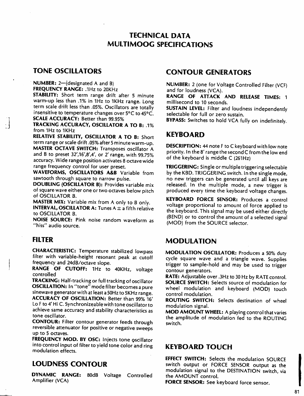
TECHNICAL
DATA
lJ
TONE
NUMBER:
FREQUENCY
STABILITY:
warm-up
term
insensitive
SCALE
TRACKING
from
RELATIVE
term
MASTER
and B to
accuracy.
range
WAVEFORMS,
sawtooth
DOUBLING
of
square
of
MASTER
INTERVAL,
to
NOISE
"hiss"
OSCILLATORS
2—(designated
RANGE:
Short
less
scale
drift
to
ACCURACY:
ACCURACY,
IHz
to 1 KHz
STABILITY,
range
or
OCTAVE
preset
Wide
frequency
through
(OSCILLATOR
wave
OSCILLATOR
MIX:
OSCILLATOR
OSCILLATOR
SOURCE:
audio
term
than
.1%
less
than
temperature
scale
drift
SWITCH:
32716',8',4',
range
control
OSCILLATORS
square
either
B.
Variable
B.
Pink
source.
MULTIMOOC
A
and
B)
.IHz
to
20KHz
range
in
Better
OSCILLATOR A TO
.05%
position
for
one
mix
A:
noise
drift
after 5
IHz
to
1KHz
.05%.
Oscillators
changes
than
OSCILLATOR A TO
or
to
narrow
B):
or
two
from A only
Tunes A ± a fifth
over
99.95%
after
5
minute
Transposes
2'
range,
activates
user
A&B
Provides
8
preset.
Variable
pulse.
octaves
random
waveform
SPECIFICATIONS
CONTOUR
NUMBER: 2 (one
minute
range.
5°C
Long
are
totally
to
45°C
B:
.1%
B:
Short
warm-up.
oscillator
with
octave
variable
below
to B only.
A
99.75%
wide
from
mix
pitch
relative
as
RANGE
SUSTAIN
BYPASS:
KEYBOARD
DESCRIPTION:
priority.
of
TRIGGERING:
by
no
produced
KEYBOARD
voltage
GENERATORS
for
and
for
loudness
OF
millisecond
LEVEL:
selectable
the
the
new
released.
for
Switches
I n the
keyboard
KBD.
triggers
In
every
proportional
the
keyboard.
(BEND)
(MOD)
or
to
from
(VCA).
ATTACK
to
10
seconds.
Filter
full
or
to
44
note F to C keyboard
8'
range
is
middle C (261
Single
TRIGGERING
can
the
multiple
time
FORCE
This
signal
control
the
SOURCE
Voltage
zero
hold
the
or
be
the
SENSOR:
to
the
Controlled
AND
and
multiple
generated
amount
RELEASE
loudness
sustain.
VCA
fully
second C from
Hz)
triggering
switch.
keyboard
In
mode, a new
Produces a control
of
may
be
used
amount
of a selected
selector.
Filter
(VCF)
TIMES:
independently
on
indefinitely.
with
low
the
selectable
the
single
until
all
keys
trigger
voltage
force
changes.
applied
either
1
note
low
end
mode,
are
is
to
directly
signal
FILTER
CHARACTERISTIC:
filter
with
variable-height
frequency
RANGE
controlled
TRACKING:
and
OF
Half-tracking
OSCILLATION:
sinewave
ACCURACY
Lo F to
achieve
tone
CONTOUR:
reversible
up
FREQUENCY
into
modulation
generator
OF
4'
Hi
C.
same
oscillator.
Filter
attenuator
to 5 octaves.
MOD.
control
input
effects.
LOUDNESS
DYNAMIC
Amplifier
RANGE:
(VCA)
Temperature
resonant
24dB/octave
CUTOFF:
In
"tone"
with
OSCILLATION:
Synchronizeable
accuracy
contour
for
BY
of
filter
slope.
IHz
or
full
mode
at least
and
stability
generator feeds
positive
OSC:
to
yield
CONTOUR
80dB
stabilized
peak
to
40KHz,
tracking
filter
becomes
a
50Hz
to
Better
with
tone
characteristics
or
negative
Injects
Voltage
tone
tone
lowpass
at
cutoff
voltage
of
oscillator
a
pure
5KHz
range.
than
99%
16'
oscillator
to
as
through
sweeps
oscillator
color
and
ring
Controlled
MODULATION
MODULATION
cycle
square
trigger
contour
RATE:
SOURCE
wheel
control
ROUTING
modulation
MOD
the
switch.
to
generators.
Adjustable
SWITCH:
modulation
modulation.
AMOUNT
amplitude
KEYBOARD
EFFECT
switch
modulation
the
FORCE
SWITCH:
output
AMOUNT
SENSOR:
OSCILLATOR:
wave
sample-hold
and a triangle
over
.3Hz
Selects
and
SWITCH:
signal.
of
Selects
WHEEL: A playing
modulation
TOUCH
Selects
or
FORCE
signal
to
the
control.
See
keyboard
Produces a 50%
wave.
and
may
be
used
to
30
Hz
by
RATE
source
keyboard
the
DESTINATION
of
modulation
(MOD)
destination
control
fed
to
modulation
SENSOR
force
that
the
ROUTING
output
switch,
sensor.
duty
Supplies
to
trigger
control.
for
touch
of
wheel
varies
SOURCE
as
the
via
81
Page 77

AMOUNT
to
the
DESTINATION
modulation
SYNCH A TO
switch,
the
fundamental
routed
of A resulting
CONTROL:
DESTINATION
SWITCH:
signal
to
one
B:
In
this
oscillator
A
is
reset
frequency
into
oscillator
in
A
dynamic
Attenuates
switch.
Sends
or
more
positionof
by
shifts
spectrum
the
the
keyboard
of
six
control
the
DESTINATION
oscillator
of A to
the
B.
harmonic
changes.
signal
applied
touch
inputs.
B
which
locks
Modulation
structure
RIBBON
adjustment
KBD
SENSOR
GLIDE
an
Position).
OUTPUT:
FORCE:
ON/OFF:
external
Outputs 0 to 6 VDC
mechanism
Provides
foot
±.6VDC
under
switch
full
keyboard.
glide
(front
scale
with
from
ON/OFF
control
panel
GLIDE
±20%
FORCE
with
on
SAMPLE
FUNCTION:
modulation
control
S
& H
AUTO:
synchronously
Trigger
S
& H
keyboard
&
HOLD
Samples
oscillator
steps
that
occur
Modulation
at
the
beginning
duty
cycle = 50
KBD:
Sampling
alone
triggers
noise
to
at a regular
%.
rate
contours.
GLIDE
Exponential
millisecond
Glide
stops
portamento
to 5 seconds
when
no
with
key
is
RIBBON
Supplies
A
switch.
released.
pitch
bend
and
B,
determined
Automatic
signal
by
reset
to
source
yield
at
rate
randomly
changing
tempo.
oscillator
triggers
of
each
still
set
adjustable
GLIDE
ON/OFF
contours
control
mod.
osc.
from
depressed.
to
oscillator
the
center
A
or
oscillator
RIBBON
ROUTING
when
ribbon
MODULATION:
external
external
set
by
step.
but
also
equipment
external
FILTER
filter.
100K.
OSC.
oscillators.
impedance
1
switch.
S-TRIG INPUT:
generators.
"bounce."
AUDIO
processed
required
is
TOUCH
source
modulation
Input
This
input/output
switch
pedal
be
used
equipment.
INPUT:
Scaling
A&B
INPUT:
MOD
to
impedance = 30K.
to
turn
to
control
to
route
or
feed
Allows
is
0.95
volts/octave.
INPUT:
Allows
Scaling
=
100K.
Switch
Internal
Input
impedance
Allows
through
for
full
be
used
source.
synthesizer.
drive.
EFFECTS:
to
replace
Maximum
modulation
in
is
circuit
jack
modualtion
amount
modulation
external
external
0.95
closure
external
Input
Allows
internal
on
and
of
modulation.
signal
to
signal
voltage
Input
voltage
control
impedance
volts/octave.
triggers
fully
removes
=
100K.
sound
impedance
external
source
100MV
RMS
=
modulation
keyboard
input
3 V peak
allows
off,
an
or
an
May
external
from
of
=
control
of
Input
contour
switch
to
be
input
100K.
touch
to
peak.
REAR
LOW
AUDIO
output
HI
output
S-TRIG
contour
by
Compatabie
Accessories.
ground.)
KBD
octave
TRIG
without
keyboard
when
82
impedance
AUDIO
impedance.
OUTPUT:
front
OUT:
adjustable
EXT
adjustment
PANEL
OUTPUT:
OUTPUT:
Output
generators
panel
KBD & TRIG
with
(An
S-Trig
Keyboard
over+10%
OUT
switch
ribbon,
input
or
to
override
pot
-10
+12
Will
drive
ar
triggered
all
Moog
is a "switch"
voltage
turns
on
with
is
in
dBM
max
level
dBM
max
level
headphones.
trigger
occurs
but
can
EXT
OUTPUT
whenever
be
Synthesizers
or
closure
with
glide
at 1 volt
range.
keyboard
click
Front
panel
KBD
OUT
ribbon.
May
be
control
position.
off,
ACCESSORY
at
1K
at
1.5
K
POWER
90-130
disabled
switch.
50/60
Detachable
and
to
DIMENSIONS
OVERALL
per
KBD
&
or
on
used
as
voltage
NET
at
50
MA
Hz.
WEIGHT:
POWER.-Supplies
max
for
all
standard
±15V
MOOG
REQUIREMENTS
VAC
or
180 -260
18
Watts
international
SIZE:
313/*
26
lbs.
VAC
power
AND
wide
15"
cord
WEIGHT
deep x SVi"
regulated
accessories.
D.C.
high.
 Loading...