

Page 1
5KHz
20KHZ
20Hz
320Hz
80Hz
FINE TUNE
MIDI
FREQ
MIX
MOD
ENVELOPE
VCO 2
FILTER
VCA
RELEASE
LFO RATE
VCO LFO AMT
VCF LFO AMT
ATTACK
DECAY/
RELEASE
SUSTAIN
GLIDE
GLIDE RATE
VCO 1 LVL
VCO 2 LVL
CUTOFF
RES
EG AMOUNT
FILTER
AMPLIFIER
VOLUME
/
Page 2

MINITAUR
Congratulations on your new Minita ur Analog Bass Synthesizer, a powerful, compact
Moog synthesizer with a classic one knob per function de sign. At only 8 .5" x 5. 25"
and less tha n 3lbs, the Minitaur puts legendar y analog M oog bass into a package
designed to fit seamlessly into all of your perfo rmance and production environments.
The Minitaur will bring you many happy years of creative and sonic enjoyment. We
are sure you are anxious to start playing, so refer to the “Getting Started” guide or look
over the Setup and C onnec tions section to get going . At some point, we encourage
you to spend some tim e with this manual to discover all that the Minitaur has to of fer.
Don’t fo rget - E xperimentation and lea rning will reward you with a lifetime of
rich synthesizer experiences .
IMPORTANT SAFETY INSTRUCTIONS
PLEASE READ BEFORE USING THIS PRODUCT
When using th e Minitaur, these basic precautions should always be followed.
1. Read all the instructions before using this product.
2. Do not use the Minitaur near water.
3. This product, in combination with an amplifier and headphones or speakers,
may be capable of producing sound levels that could cause permanent
hearing loss. Do not op erate for a long period of time at a high volume level
or at a level that is uncomfortable. If you experience any hearing loss or
ringing in you r ears, you should consult an audiologist.
4. Keep the Min itaur away from he at sources such as radiators, heat registers,
and other products that produce heat.
5. The product should be connected to a power supply only of the type
describe d in the operating instructions .
6. The power supply shoul d be unplug ged from the outlet when left unuse d
for long periods of time .
7. Care should be taken so th at liquids are not spilled into the front panel.
8. The Minitaur should be ser viced by qua lified pe rsonnel when:
a. Objec ts have falle n, or liquid has bee n spilled o nto the product.
b. The produ ct has be en exposed to ra in.
c. The prod uct does not appear to operate no rmally or exh ibits
a marked change in per formance.
d. The product has been dropped or the enclosure damaged.
DANGER -- INSTRUCTIONS PERTAINING TO RISK OF FIRE, ELECTRIC
SHOCK, OR INJURY TO PERSONS: Do not open the cha ssis. There are no
user serviceable parts inside. Refer all servicing to qualifie d personnel only.
!
Page 3

UNPACKING AND INSPECTION
CHECK THE CONTENTS IN THE SHIPPING CARTON
The Minita ur is shipped with the following items:
1. The Minitaur Analog Bass Synthesizer
2. A 12VDC Power Adaptor
3. A “Getting Started” guide
4. Registration Card
5. Earplugs
WHAT YOU WILL NEED
1. A MIDI keyb oard or MI DI controller
2. A MID I cable
3. A USB cable to connect the Minitaur to a host computer (for USB MIDI)
4. A 1/4” instrument cable and amplifier, or a pair of headphones with
an 1/8” plug
SETUP AND CONNECTIONS
NOTE: We encourage you to read the entire manual at some point to learn
more about the instrument and gain a better understanding of what you
can do with the Minitaur.
SET U P
Use care when unpacking your M initaur, and be sure to save the carton and
all packing material in case you need to ship it for any reason.
CONNECT TO POWE R & MIDI
Connect the supplied Power Adaptor to the Minitaur’s 12VDC power jack on the
back of the unit. The Minitaur’s universal power supply will operate with a
power source from 100 to 240 Volts AC , 50/60Hz. Using a 5 Pin MIDI cable,
make the connect
ion between MIDI OUT of your MIDI controller and the MIDI
IN on the Minitaur. The Minitaur is set to receive messages on MIDI Channel 1, so
make sure your controller is set to transmit on MIDI Channel 1. If you are using
USB M ID I, connect th e US B ca ble from th e Mi nitaur to a US B port on your
computer. The Minitaur’s USB drivers are automatically installed, and it will appear
as ‘Moog Minitaur’ (Mac OSX or Win 7) or ‘USB Audio Device’ (Win XP) in the
MIDI Device selectio n options of your computer’s MIDI software.
4
CONTENTS
THE BASICS
Unpacking & Inspection•••••••••••••••••••••
Setup and Connections••••••••••••••••••••••
Overviews and Features•••••••••••••••••••••
Signal Flow•••••••••••••••••••••••••••••••••••
Basic Operation••••••••••••••••••••••••••••••
THE COMPONENTS
Oscillators••••••••••••••••••••••••••••••••••••
Glide••••••••••••••••••••••••••••••••••••••••••
Mix••••••••••••••••••••••••••••••••••••••••••••
Filter••••••••••••••••••••••••••••••••••••••••••
Envelopes••••••••••••••••••••••••••••••••••••
Release•••••••••••••••••••••••••••••••••••••••
Modulation•••••••••••••••••••••••••••••••••••
Volume•••••••••••••••••••••••••••••••••••••••
Input/Output Panel••••••••••••••••••••••••••
MIDI OPERATIONS
MIDI CC Table••••••••••••••••••••••••••••••••
APPENDICES
A. MIDI Implementation Chart•••••••••••••••
B. Service & Support Information•••••••••••
C. Caring for Minitaur•••••••••••••••••••••••
D. Using the CP-251 with Minitaur•••••••••••
E. Specifications••••••••••••••••••••••••••••
4
4
6
8
9
9
11
11
12
14
15
16
17
18
22
25
26
27
27
29
Page 4
POWER UP
Apply power to the Minitaur and to your MI DI controller.
CONNECT TO AMP LIFIER
Set the Minitaur’s volume control to minimum before connecting to an amplifier,
mixer, or h eadphones. Set th e amplif ier volum e to a comfor table l isten ing
level, and then slowly bring up the volume on the Minitaur as you play a few notes.
NOTE: Use caution when adjusting initial volume levels, especially if connected
to a subwoofer.
START PL AYING
Since the Minitaur is a Bass Synthesizer; it operates exclusively in the lower
note range (M IDI notes 0 - 72). This me ans th at the Minit aur will respond
to your p laying from ‘ C4’ (an octave above middle ‘C ’) dow nward. Play
some n otes, tweak some knobs and have so me fun!
DOWNLOAD THE MINITAUR EDITOR PR OGR AM
Register your Minitaur online at www.moogmusic.com/register to download
the fre e Minitaur Editor Program . This allows you to load and s ave patches
and access all o f the Mi nit aur ’s under th e hood featu res . Re gister ing your
Minitaur a lso initiates your warranty, ensures you receive the latest software
updates, and g ets you a nif ty sticker !
NOTE: A wa rm up p erio d of about 15 minutes is recom mended for th e Minitaur
to reach concert pitch. The warm up period may be a little longer if the M initaur
has been stored outside the recommended operating temperature range.
The recommended operating temperature of the Minitaur is between 50 and 100
degrees Farenheit. It is safe to operate the synthesizer outside of this range, but the
Minitaur’s voltage controlled oscillators may not remain in tune. It is also recommended that the Minitaur not be exposed to direct sunlight while operating.
5
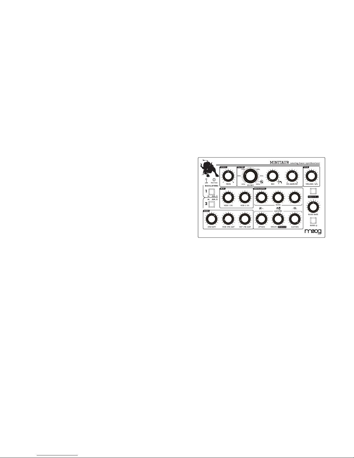
OVERVIEW AND FEATURES
The Minitaur is a monophonic Analog Bass Synthesizer with a 100% analog audio
path. It is based on the legendary Taurus I and Taurus 3 Synthesizers. The Minitaur
features 2 ultra -stable voltage controlled oscillators, a genuine M oog low pass
filter, 2 envelope generators and a modulation circuit. The Minitaur has a classic
one knob per functi on design in a rugged performa nce package that is s mall
enough to take with you anywhere.
OSCIL LATORS
Two Voltage Controlled Os cilla tors with selec table S awtooth (origina l
Taurus) and Square waveshapes.
MIX
Mixer for adjusti ng VCO levels independently.
FILTER
Classic Moog 24dB/Octave Low Pass Filter with adju stable Resonance.
ENVE LOPES
Twin Minimoog style ADS R Envelope Generators for modulatin g the
Filter ( VCF) and Amplifier (VCA). The Envelope Dec ay and R elea se
se gm e nt s a re c on troll ed by th e DE CAY kno b, w hi le t h e Re le ase
segment is e nabled or disabled v ia the RELE ASE switch .
MOD
MIDI -syncable Low Frequency Os cilla tor (LFO) with Rate control and
and in divid ual VCO and VCF AMOU NT controls .
FRONT PANEL
6
Page 5
7
HEAD PHONE OUT
1/8” Stereo H eadph one O utput.
AUDIO OUT
1/4” Unba lanced Out put.
AUDIO IN
Ext ern al A udi o In put for processing aud io t hro ugh th e Mixer and Filter
secti on of th e Minitaur.
CONTROL IN PUTS
Ana log control input s fo r Pitch , Filter, Volum e and Gate . U se contr ol
vol ta ge or a M oo g EP2 ex pr es si on pe da l to co nnec t a nd co ntrol th e
Min it au r wit h e very th in g fr om Mo og er fo og er s to modula r sys te ms .
MIDI
DIN MIDI and USB MIDI of fer complete control of the Minitaur’
s sound engine.
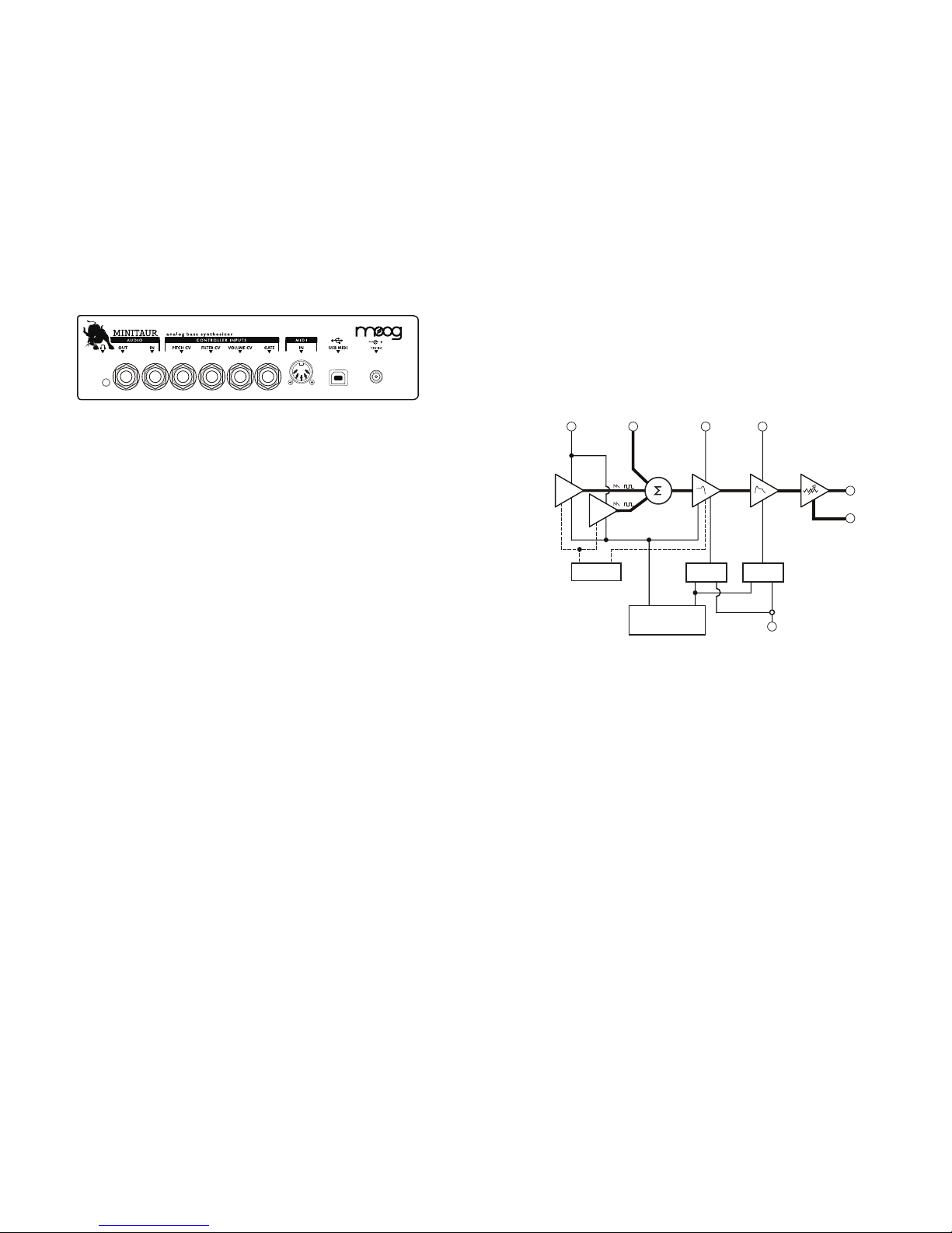
BACK PANEL
SIGNAL FLOW
To understand how the Minitaur generates sound, take a look at the diagram
below. It shows the flow of Audio, Control Voltage and Modulation signals in
the Minitaur. Heavy lines indicate audio signals, which flow from left to right.
Lighter lines indicate Control Voltages (CV’s), which flow from the top and
from the bottom. Dotted lines indicate Modulation routings.
The Minitaur’s source signals are created by two Voltage-Co ntrolled Oscillators (VCO) which are mixed with the External Audio I nput. The Mixer
Output is routed to the Filter, where the ton e is sculpte d according to th e
Filter pa rameter s and the Fil ter AD SR Envelope. Th e signal is then passed
to the Amplif ier ( VCA) stag e, where the Volume ADSR envelo pe shapes it.
Finally, the signa l is rou ted to th e Output se ction, where
the final level is
set by the Volume control knob.
For most users, MIDI will be the main source of control for the Minitaur. Each
time the Minitaur receives a MIDI “Note On” command, it produces a Pitch CV
and Gate signal in response. The Pitch CV signal sets the Pitch of the Oscillators,
while the Gate signal triggers the Filter and Volume ADSR Envelop es.
The Mi nitaur can also be oper ated vi a CV and G ate trigger co nnections ,
for a mo re ‘old school ’ meth od of control . Both control meth ods (MIDI &
CV/Gate) can be used at the s ame time, altho ugh s ome combinations of
control signal s may ca use unpredictable results .
NOTE: DIN MI DI IN is not passed to USB MIDI OUT
PITCH CV INPUT
OSCILLATORS MIX FILTER VOLUME
HEADPHONES
ENVELOPES
GATE INPUT
MIDI IN >
VCA
(AMPLIFIER)
AUDIO
OUT
AUDIO INPUT FILTER CV INPUT VOLUME CV INPUT
FILTER
ADSR
PITCH CV
GATE
MIDI/CV CONVERTER
MODULATION
(LFO)
VOLUME
ADSR
1
2
/
/
8
Page 6
BASIC OPERATION
The Minitaur responds to MIDI messages on both DIN and USB MIDI Inputs.
In addition, Minitaur’s knobs and switches transmit MIDI Control Change
(CC) commands via MIDI USB, allowing parameter adjustments to be
captured by any MIDI-recording device. Minitaur has an LED MIDI indicator
that indicates MIDI activity on either the DIN MIDI or USB MIIDI connector.
To further extend the Minitaur’s capabilities, there are additional parameters
that can be accessed via MIDI control. A complete list of all MIDI CC commands
can be found on page 22-23.
The frequencies of both Oscillators are affected by a number of sources. The
main source is a ‘Note On’ command transmitted from an external MIDI
controller or DAW. The ‘Note On’ command is translated into a Control
Voltage that allows the Oscillators to be played in an equal-tempered scale.
Other control sources include Minitaur’s GLIDE circuit, VCO 2 FREQ, the
PITCH CV INPUT, the FINE TUNE control, and the output of the MODULATION
(LFO) circuit. The highest pitch produced by Minitaur’s Oscillators is C5
(523.25 Hz) or MIDI note value 72.
PANEL CONTROL S FOR THE OSC ILLATOR
OSCILLATOR 1 Switch (CC# 70):
Select s a Sawtooth (LED OFF ) or Squ are wave (LED ON) for VCO 1.
OSCILLATOR 2 Switch (CC# 71):
Select s a Sawtooth (LED OFF ) or Squ are wave (LED ON) for VCO 2.
VCO 2 FREQ (CC# 17):
Sets the freque ncy of fset of VCO 2 from VCO 1. The offset range is +/-1
octave. Center position tunes VCO 2 in uniso n with VCO 1. NOTE: If playing
between notes 60 and 72, the pitch of VCO 2 is limited to note 72 (C4)
regardless of this control setting.
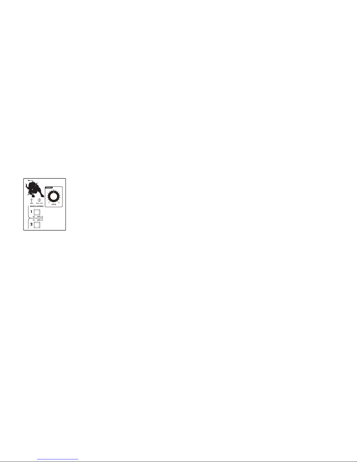
The Oscillators are the main sound source of Minitaur.
They create electronic vibrations that can be tuned
and amplified into sound that we can hear. The
Minitaur’s VCOs can produce a total musical range
of 6 octaves.
OSCILLATOR 1 (VCO 1) serves as a master Oscillator
to which OSCILLATOR 2 (VCO 2) is tuned. Two
independent switches select the waveform for
each Oscillator (Sawtooth or Square). A FINE TUNE
control adjusts the master tuning of both Oscillators.
THE COMPONENTS
OSCILLATORS
9
FINE TU NE:
Adjusts the freque ncy of both VCOs by approximately +/-1 semitone. The
FINE TU NE control does not transmit M IDI.
MIDI ACCESSI BLE CONTROL
VCO 2 BEAT (CC# 18):
Select s the fine freque ncy offset for VCO 2 . The adjustment range is
+/- 50 cents.
Default = 64.
NOTE SYNC (CC# 81):
When enabled, NOTE SYNC forces both oscillators to s tart at the same
time, eliminating a ny phase differences at the start of each “ Note On”
command . This ensures energy is consistent at th e start of each new note.
Default = OFF.
EXTER NAL CONTROL
The PITCH CV jack on the back pane l is a CV input for external control of
the Oscillator pitch. This input controls the fre quencies of both Oscillators.
A 1 volt change of this voltage will change the pitch by one o ctave. The
jack acce pts 0 to +5 volts, or an expression pedal like the Moog EP-2.
PERFO RMANCE TIPS:
• For punchy bass lines, try using NOTE SYNC to keep the
energy at the beginning of each note the same.
• A steady control voltage applied to the PITCH jack will
offset the base pitch of both oscillators. You can use this
feature to transpose the oscillators to any desired interval.
• To recreate the classic Taurus sound, choose the Sawtooth
wave for one or both oscillators.
10
Page 7

The FILTER is a classic Moog 24dB/
Octave Low-Pass Filter design with
resonance. It has controls for CUTOFF
frequency which determines the range
of frequencies the filter will affect, as
VCO 2 LVL (CC# 16):
Sets the level of VCO 2.
MIDI ACC ESS IBLE CO NTRO L
EXTE RNAL I NPUT LEVEL (CC# 27):
Adjusts the External Audio Inpu t level . By de fault, the level is set for unit y
gain, but the level can b e adj usted up to 20 0%
Default = 64.
PANEL C ONTRO LS FO R THE FILTER
CUTOF F (CC# 1 9):
Adjusts the CUTOFF freq uency of the Low Pass Filter from 20 Hz to 20 KHz.
As the knob is rotated clockwise, the cutoff frequency is increased, allowing
more h armo nics to pass through the filter, resulting in a b righter sou nd.
Conversely, as the knob is rotated counterclockwise, the sounds get darker.
NOTE: The Min itaur may not p roduce sound whe n this c ontrol i s turn ed all
the way down.
RESO NANCE ( RES) (CC# 21):
Sets the amount of signal sent from the FILTER output to be fed ba ck into
it’s input. This creates a peak in the fre quency that can be incre ased all the
The FILTER provides either fix
ed or
dynamic timbre modifications. Dynamic changes are provided by the
Filter Envelope Generator (EG), a Low
Frequency Oscillator (LFO), or by an
externally applied Control Voltage.
well as RESONANCE, which determines how much emphasis is applied to the
harmonics near the Cutoff frequency (see figure).
FILTER
Resonant Peak
Frequency
Frequency response of a Low Pass Filter
with Resonance
Amplitude
12
GLIDE (AKA ‘portamento’) is a musical effect that makes smooth
changes in pitch between notes. The Minitaur’s GLIDE RATE is
adjustable from instantaneous to extremely long.
GLIDE
Each Oscillator (VCO 1 & VCO 2) has a dedicated level
knob that allows you to control the relative strength of
each oscillator from 0 to 100%. NOTE: The VCOs begin
to clip the filter at about 2 o’clock creating more
agressive sounds.
MIX (OSCILLATOR LEVELS)
PANEL C ONTRO LS FO R GLIDE
GLID E Switch (CC# 65):
Enables /Disables the G LIDE fu ncti on. GLID E is on when the LED is o n.
GLID E RATE (CC# 5):
Sets the rate of GLIDE that occurs when the note controlling the Minitaur changes.
MIDI ACCESSIBLE CONTOL
GLIDE TYPE (CC# 92):
The Mintaur offers three GLIDE types: Linear Constant Rate (LCR), Linear Constant
Time (LCT), or Exponential (EXP). When LCR is selected, the GLIDE RATE stays
the same regardless of the interval. When LCT is selected, the GLIDE TIME stays
the same regardless of the interval. When EXP is selected, the GLIDE RATE follows
an exponential curve that starts fast and then slows as it approaches the target
note (like the Taurus).
Default = LCR.
LEGATO GLIDE (CC# 83):
Normally, GLIDE occurs with every new note. When LEGATO GLIDE is enabled,
however, GLIDE is only applied when a new note is received while another note
is still being held.
Default = OFF.
PANEL C ONTRO LS FO R THE M IXER
VCO 1 LVL (CC# 15 ):
Sets the level of VCO 1.
11
Page 8

way to self-osci llation.
EG AMOUN T (CC# 2 2):
Deter mi ne s h ow mu ch t he Fil te r Envel op e G enera tor (E G) add s to or
subtracts from the Filter Cutoff control setting. When the EG AMOUNT knob
is set to positi ve (+), turn the F ILTER CUTOFF knob left to hear th e effect.
When the EG AMOUNT kn ob is set to ne gative (-), turn the FILTER CUTOFF
knob rig ht to hear the effect. Note that if the Cutoff frequency is set very high,
a positive EG Amount may have little or no noticeable effect, regardless of the
setting. Similarly, if the Cutoff frequency is set low, a negative EG Amount may
have little or no noticeable effect.
MIDI ACCESSIBLE CONTROL
FILTER KB TRACKING (CC# 20):
Determin es h ow the Filter Cutoff changes i n response to MI DI N ote O n
valu es. Filter tracking is adjustable from 0 to 200% .
Default = 32 (about 50%).
FILTER VELOCIT Y SENSITIVITY (CC# 89):
Sets the amount OF MIDI Note velocity to the Filter.
Default = 64.
EXTERN AL CONTROL
The FILTER CV jack on the back panel is an input for external control of the
Filter Cutoff parameter. A voltage applied to this jack is added to the setting
of the Filter Cutoff control. A one-volt cha nge in the Co ntrol Voltage will
cha ng e th e cutof f f reque ncy of the fi lte r by ab out on e o ctave. Th e j ack
accepts 0 to +5 volts , or an expression pedal like the M oog EP-2.
13
ENVELOPE GENERATORS (EGs) add motion to
a sound after a note is played. The Minitaur has
two separate Minimoog style Envelope Generators that affect the brightness and loudness of
the Minitaur's sound by modulating the Filter
Cutoff (VCF) and Volume (VCA).
The EGs are started by a Gate or MIDI
Not e message. Once started, their
shape in time is set by th e ATTACK,
DECAY/RELEASE, and SUSTAIN controls,
as well as the Release switch and length
of the Note played.
ENVELOPES
Note On
Note Off
Amplitude
Attack
Time
Decay
Sustain
Release
PANEL C ONTRO LS FO R THE E NVELOP ES
FILTER ATTACK (CC# 23):
Set s the tim e it takes f or the Att ack por tion of the Filter EG to rise fro m
zero to maximum. Th e Atta ck tim e ranges from 1 msec to 30 secon ds.
FILTER D ECAY/RELE ASE (CC# 24):
Sets th e time for the Decay and Release portio n of the Filter EG . When a
note is held, and the Attack time end is reached, the Decay portion of the EG
starts. During the Decay po rtion, the EG moves to the Sustain level. When a
note is re leas ed, the EG moves back to zero at th e rate s et by this contro l.
This time ranges from 1 mse c to 30 second s. Th e Release segme nt of the
Envelop e is determin ed by the state of the R ELEASE switch (ON/OFF).
FILTER SUSTAIN (CC# 25):
Sets the Filter EG level after th e Decay and before the Release portio n.
A note mu st be hel d long er tha n both the Att ack and Decay time to reach
the Sustain level. The level is adjustable from 0 to 100%.
AMPLIFIER ATTACK (CC# 28):
Sets the time it takes for the Attack por tion of the Amplifier EG to rise from
zero to maximum . The Attack time ranges from 1 msec to 30 seconds .
AMPLIFIER DECAY/RELEASE (CC# 29):
Sets the time for the Decay and Release po rtion of the Amplifie r EG. When
a note is held, and Attack time end is reached, the De cay portion of the EG
starts. During the decay portion, the EG moves to the Sustain level . When a
14
Page 9

MODULATION is an important part in the creation of musically-expressive sounds. The Minitaur’s
MODULATION section provides an LFO with adjustable
RATE and AMOUNT controls for the oscillators
(VCO) and the Filter (VCF). The Low Frequency
Oscillator (LFO) is a signal used to move the pitch of VCOs and the Filter Cutoff
up and down automatically. A LFO can be used to simulate vibrato, create
wobbling filter sweeps, or make interesting synthesizer sounds.
MODULATION (MOD)
PANEL C ONTRO LS FO R MODU LATION
LFO RATE (CC# 3):
Sets the fre quency of LFO M odulation . The rang e is from 0.01Hz to 1 00Hz.
VCO LFO AM OUNT (CC# 13):
Sets the maximum amou nt the LFO moves the VCO s pitch u p and d own,
up to +/- 1 octave. Modulation affect s both Oscillators . Amounts above MIDI
Note 72 a re cli pped. If using a MI DI controll er, th
e Mod W heel (CC# 1) is
used to f ade the LFO Pitch Modulation in and out.
VCF LFO AMOUNT (CC# 12):
Sets the maximum amou nt the LFO moves the Filte r Cutoff up and down,
up to +/- 5 octaves. A mounts above 20KHz or be low 20 Hz are cl ippe d. If
using a MID I controller, the Mo d Whe el (CC# 1) is use d to fade the LFO
Filter Modula tion i n and out .
MIDI ACC ESS IBLE CO NTRO L
LFO MIDI SYNC ON/OFF (CC # 87):
En able s o r D i sables th e ab ility of th e Mi nit au r ’s L FO to s ync to M I DI
Clock me ssag es.
Default = ON.
LFO SYNC CL OCK DIVIS ION (CC # 86):
Selects the LFO Clo ck div ision when the LFO Sync Sou rce is se t to MIDI
Clock. L FO Division Settings a re lis ted on page 24. Th e LFO R ATE contro l
can also act a s a Clock Divid er.
Default = 1/4.
LFO KE Y TRI GGE R (CC# 82):
Re-triggers the start of the LFO cycle when a NOTE ON message or KB GATE
Control Voltage is received.
Default = OFF.
NOTE: When the Minitaur powers up, the settings on the VCO LFO AMOUNT
and VCF LFO AMOUNT c
ontrols have a direct effect on the VCO and VCF. This
behavior continues until the Minitaur receives a MIDI Mod Wheel command,
from which point the Mod Wheel takes master control of the LFO modulation
amount set by the Amount controls.
16
note is released, the EG moves back to zero at the rate set by this control.
The time ranges from 1 mse c to 30 seconds. The Release segm ent of the
Envelop e is determin ed by th e state of the RELEA SE switch (ON/OFF ).
AMPLIFIER SUSTAIN (CC# 30):
Sets the Amplifier EG level after the Decay and before the Release portion.
A note mu st be h eld lo nger than both the Attack and D ecay ti me to reach
the Sustain level. The level is adjustable from 0 to 100%.
MIDI ACCESSIB LE CONTROL
OUTPUT (VCA) VELOCITY SEN SITIVIT Y (CC# 90):
Sets the amount of M IDI Note velocity to the Am plifier.
Default = 6 4 (50%).
EXTER NAL CV CONTROL
The GATE jack on the back panel is a trigger input that accepts a +5V G ate
signal. Applying a Gate signal causes both Envelopes (Amplifier and Filter)
to trigger simultaneously. NOTE: When a Gate signal is applied , it overrides
triggering via M IDI. You will still be able to control the Osc illator pitch and
Mo du latio n a mounts from a M I DI co ntro ll er, bu t the envelo pe s will not
retrigger until the Gate trigger is removed.
The RELEASE switch enables or disables the Release segment of
both Envelope Generators. When enabled, the Envelope Release
time is the same as the Envelope Decay time, and the DECAY
control adjusts the time for both segments. When disabled, the
Release segment does not occur and the Envelope stops abruptly in response
to a “Note Off” message (or when the Gate CV goes to zero).
RELEASE
PANEL C ONTRO L FOR R ELEA SE
RELE ASE Switch (CC # 72):
Enables /Disables the Release function for b oth Envelope Gene rators.
RELE ASE is ena bled when the switch LED is ON .
15
Page 10

INPUT/OUTPUT PANEL
The back panel provides all of the input and output connections. In addition
to AUDIO INPUT/OUTPUT jacks, there are CV and GATE inputs, connections for
MIDI, and the Power Connector. The Minitaur does not have a power switch.
12VDC (POW ER INPUT )
A barrel conne ctor that accepts a +12VD C, tip positive powe r input f rom
the power adaptor, which accepts 10 0-240 VAC, 50 -6 0Hz.
CONTROLLER I NPUTS
The PITCH, FILTER and VOLUM E CV jacks s uppl y power and will a ccept an
expres sion pedal such as the M oog EP -2, or a Control Voltage from 0 to
+5 Volts . The GATE input accepts a +5 Volt trigger signal .
MIDI (DIN AND U SB)
Connec tions for DIN MI DI in put and U SB MI DI IN-O UT.
AUDIO IN
The AUDIO IN jack allows an ex ter
nal au dio source to be mixed with the
Minit aur ’s VCOs, and then rou ted to th e Filter for processing. Although
the M inita ur h as n o provisions fo r a dju sti ng t he leve l of t his input on
the fro nt panel, the level is adjustable up to 20 0% vi a MID I CC# 27.
AUDIO OUT
The AUDIO OUT j ack provides an un bala nced l ine-level signal for conne cting to an amplifier or mi xer.
HEADPHO NE O UTPU T
1/8” m inija ck for stereo Headphone Outp ut. 3 2Ω o r high er recommended
impedance.
18
BACK PANEL
The Minitaur features a monophonic Audio Output and a Headphone
Output; both outputs appear on the back panel. Both ouputs are
adjusted simultaneously by the VOLUME control.
VOLUME (VCA)
PANEL C ONTRO L FOR VOLUME
VOLUM E:
Adjusts the output of the Voltage C ontrolled Amplifier ( VCA) and H eadphone levels. Rot ating the control f ully clock wise p roduces the maximum
output. Rotating the con trol fully co unterclock wise silences the M init aur.
The VOLUME contro l does n ot transmit or re ceive MI DI. This is a post VCA
control.
MIDI ACCESS IBLE C ONTRO L
OUTPUT LE VEL (CC# 7):
Adjusts the Audio Output and Headph one volum e level s.
VOLUM E VELOCIT Y SE NSITIVITY (CC# 90):
Velocit y sca les th e amplitude of the Am plif ier e nvelop e Similar to traditional tou ch sensitivity.
Default = 6 4 (50%).
EXTERNA L CONTR OL
The VOL CV ja ck on the back panel is an input for ex tern al control of the
Outpu t level . A voltag e of 0 Volts silen ces th e Minitaur and a vo ltage of
5 Volts co rresp onds to the o utput level set by the VOLUM E control knob.
The ja ck accepts a positive Control Voltage f rom 0 to 5 Volts, or an ex pression pedal like the M oog EP-2.
17
Page 11

MIDI OPERATIONS
MID I CHANN EL
The Mini ta ur se nd s and rece ive s on a sin gle M IDI c hanne l. B y de fa ult,
the M inita ur is set to M ID I Cha nn el 1, bu t it can b e set to a ny MI DI
Cha nn el (1-16) . To ch ange th e MIDI Ch an nel on t he Mi ni ta ur:
1. Conne ct yo ur MI DI co nt rolle r or DAW to the M in itaur.
2. Adj us t the cont rol le r (or DAW) to t ran smit the de sired
MID I Chann el .
3. O n the Mi ni tau r; p re ss an d ho ld al l fo ur pan el s w
itch es
(VCO 1 Wave , VCO 2 Wave, G LID E and RE LE ASE ). The pane l
sw i t c h LE Ds will bl ink , i ndi cating tha t t h e M i nita ur is
waiting to se t the n ew MIDI ch annel . The n ext MI DI messa ge
tha t the M in ita ur re ceive s (a N ote On , CC, P itch Be nd et c. ..)
will s et the new c hanne l.
4. On ce in lear n mode, p res s a k ey on the M IDI con tro ll er(or
send MIDI data from the DAW). The Minitaur will reset its MIDI
cha nnel to matc h t he c hanne l b eing se nt .
Ch an ges
to t he Mi ni t au r ’s MIDI ch an nel a re wr it ten t o m em ory a nd
are re membe red o n powe r dow n.
MID I NOT E RAN GE
The Minitau r responds to MIDI Note values 0-72; note values of 73 a nd
hig he r are ig no red .
PITCH BE ND RE SP ONSE
By d e fa u lt , th e P I TCH BE N D R ES P ONS E o f the Minit a ur is se t t o + / - 3
semi to n es. Th e P itc h B end u p a n d d ow n v alu es c an be adj ust ed
ind ep enden tly by issui ng new val ues f or MIDI CC#1 07 (Pi tch Be nd UP)
and CC # 10 8 (Pi tch B en d DOWN). S ee th e MIDI CC Me ss ages Table f or
the ra ng e of value s.
MOD UL ATION W HE EL (M OD WHEE L) R ESPON SE
MIDI Mod Wheel messages cont rol t he maximu m amount of modul ation
effect set by th e VCO L MO AMT and VCF LFO AMT controls (MIDI CC# 1) .
20
PERFO RMANCE TIPS:
• You can use the Minitaur to process any audio signal simply
by plugging into the AUDIO IN jack. To hear the external
audio signal, you will need a MI DI NOTE ON message. To
hear the external audio signal without issuing a M IDI NOTE
ON message, apply +5V to the GATE jack. This will leave
the Gate open, and the A mplifier Envelope will remain at
its Sustain level until the Gate closes .
• The M initaur’s audio input is not limited to processing
monophonic sig nals - it can work well for processing
polyphonic signals, too. For example, connect the Audio
Output of a MIDI-e quipped polyphonic keyboard to the
Minitaur’s AUDIO IN jack, and turn the MIX level of VCO 1
and VCO 2 all the way down on the Minitaur. Now you
have a polyphonic source affected by the M initaur’s
Filter and Envelope circuits - a great way to warm up a
sterile digital signal!
19
Page 12

SECTION
MOD(MODULATION)OSCILLATORSMIXERFILTER
FUNCTION CC VALUE/RANGE
CONTROL/
PARAMETER
LFO RATE Adjusts the LFO frequency
3(MSB)
35(LSB)
0-127
0-127
0-127
0-63(INT)
64-127(MIDI CLOCK)
See table on
page 24
0-63(OFF)
64-127(ON)
0-63(SAW)
64-127(SQR)
0-63(SAW)
64-127(SQR)
0-63(OFF)
64-127(ON)
0-63(OFF)
64-127(ON)
0-42(LCR)
43-84(LCT)
85-127(EXP)
0-63(Always Glide)
64-127(Glide on
legato notes only)
0-127
(64 is center)
0-127
0-127
0-127
0-127
0-127
0-127
0-127
0-127
0-127
0-127
13(MSB)
45(LSB)
12(MSB)
44(LSB)
87
86
82
70
71
17(MSB)
49(LSB)
18(MSB)
50(LSB)
15(MSB)
47(LSB)
16(MSB)
48(LSB)
27(MSB)
59(LSB)
19(MSB)
51(LSB)
21(MSB)
53(LSB)
22(MSB)
50(LSB)
20(MSB)
54(LSB)
89
81
65
92
83
5(MSB)
LFO VCO AMOUNT Adjusts the modulation amount
to the VCOs
LFO VCF AMOUNT Adjusts the Modulation amount
to the VCF
LFO MIDI SYNC
(M)
LFO SYNC CLOCK
DIV (M)
Sets the LFO synchronization
clock divider
Enables or disables ability of LFO
to sync with MIDI CLOCK messages
LFO KEY TRIGGER
(M)
VCO 1 WAVE Selects the waveform of VCO 1
Selects the waveform of VCO 2
Adjusts the frequency of VCO 2
Adjusts the beat frequency of
VCO 2 (Default is 64)
Enables
/disables Note Sync
(Default is off)
Adjusts the Glide (portamento)
rate time
22
Sets the state of the GLIDE switch
(Glide is enabled when LED is lit)
Selects the type of Glide; Linear
Constant Rate, Linear Constant Time,
or Exponential.
Sets the state of the Legato Glide
parameter when GLIDE is enabled
(Default is OFF)
VCO 2 WAVE
VCO 2 FREQ
VCO 2 BEAT
(M)
GLIDE RATE
NOTE SYNC
(M)
GLIDE SWITCH
GLIDE TYPE
(M)
LEGATO GLIDE
(M)
VCO 1
CUTOFF Adjusts the Filter Cutoff frequency
RESONANCE Adjusts the Filter Resonance
parameter
EG AMOUNT Adjusts the EG amount affecting
the cutoff
FILTER KB TRACK
(M)
Sets the amount of keyboard tracking
for the filter (Default is 32 - about 50%)
FILTER VELOCITY
SENSITIVITY (M)
Sets the amount of filter velocity
sensitivity (Default is 64 - 50%)
Adjusts the level of VCO 1
VCO 2 Adjusts the level of VC0 2
EXTERNAL IN
LEVEL (M)
Adjusts the level of the External Audio
Input (Default is 64 = 50% level)
Re-triggers the LFO to the start of
the cycle (Default is OFF)
MIDI CO NTROL CHANGE (CC) MESSAGES
The tables on the followin g pages list all MIDI CC message s f or the
Min itaur. Messag es shown with an (M) indicate paramet ers which are
only accessible via MIDI. Bolded values indicate the appropriate range
for 7-bit mess ages (MS B).
NOTES :
•
The Minitaur sends 7-bit MIDI CC messages for all parameters.
It can receive eith er 7-bit o r 14-bit values f or the par ameters
controlled by knobs, but only 7-bit values for parameters con trolled by switches.
• For all parameters, the MSB indicates the ‘regular’ CC number,
and the LSB indicates the high-resolution ‘ fine’ control value.
If you are only sending 7-bit MIDI CC messages to the Minitaur,
use the MS B n umbe r by it self. N ot e th at w he n MSB -o nly
messages are issued, the value range is always 0-127.
A NOTE ABOUT CONTROL PARAMETERS
LOCAL CONTROL OF F (CC# 122):
This parameter allows the front panel controls to send MIDI, but disconnects
the Minitaur sound eng ine fro m direct control by the panel. Per the MID I
spec, only values of ‘0’ and ‘127’ work (0 = OFF, 127 = ON). If you are connected to a DAW using U SB MIDI pa tched thro ugh, you may n eed this to
avoid feedback artifacts. After changing the state of LOCAL CONTROL
on/off, the Minitaur remembers th e last setting after power down.
ALL SOUN DS OFF/ALL NOTES OFF (CC# 120 or 123):
Both of these parameters are MIDI ‘panic’ functions that are used to silence
hung MID I notes. Controllers or DAWs may send one or the other command
which is why the Minitaur will respond to either.
21
Page 13

SECTION
ENVELOPES
MOD
WHEEL
RESPONSE
PITCH WHEEL
RESPONSE
CONTROL
(SEE NOTE 1)
KEYBD
RESPONSE
VOLUME
FUNCTION CC VALUE/RANGE
CONTROL/
PARAMETER
VCF ATTACK Adjusts the filter envelope attack
time.
23(MSB)
55(LSB)
0-127
0-127
0-127
0-127
0-127
0-127
0-63(OFF)
64-127(ON)
0-42(LEGATO ON)
43-84(LEGATO OFF)
85-127(EG RESET)
0-42(LOW)
43-84(HIGH)
87-127(LAST)
0-15(OFF)
16-31(2 SEMITONES)
32-47(3 SEMITONES)
48-63(4 SEMITONES)
64-79(5 SEMITONES)
80-95(7 SEMITONES)
96-111(12 SEMITONES)
112-127(24 SEMITONES)
0-127
0-127
Any Value
0 = OFF
127 = ON
Any Value
24(MSB)
56(LSB)
25(MSB)
57(LSB)
28(MSB)
60(LSB)
29(MSB)
61(LSB)
30(MSB)
62(LSB)
72
73
7(MSB)
39(LSB)
90
120
123
91
107
108
122
1(MSB)
33(LSB)
VCF DECAY/
RELEASE
Adjusts the filter envelope decay
and release time
VCF SUSTAIN Adjusts the filter envelope
sustain level
VCA ATTACK
VCA DECAY/
RELEASE
Adjusts the volume envelope
decay and release time
Adjusts the volume envelope
attack time
VCA SUSTAIN
RELEASE SWITCH Sets the state of the Release
parameter (enabled when LED is lit)
Sets the state of the envelope
trigger (Default is Legato ON)
Adjusts the audio ouput and
headphone volume.
Sets the amount of volume velocity
sensitivity (Default is 64 = 50%)
Sets the Note Priority
(Default is last)
Modulation performance control
Pi
tch Wheel ‘UP’ performance
control (Default = +3 semitones)
Pitch Wheel ‘UP’ performance
control (Default = -3 semitones)
Sets the state of the Local Control
OFF parameter (Default is 127)
TRIGGER MODE
(M)
VCA (OUTPUT)
LEVEL (M)
VOLUME VELOCITY
SENSITIVITY(M)
MOD WHEEL(M)
KEY PRIORITY(M)
BEND UP AMOUNT
(M)
BEND DOWN
AMOUNT(M)
LOCAL CONTROL
OFF(M)
ALL SOUNDS OFF
(M)
MIDI Panic message (Shuts off hung
MIDI notes)
MIDI Panic message (Shuts off hung
MIDI notes)
ALL NOTES OFF
(M)
Adjusts the volume envelope sustain
level
-
23
TIME VALUE DIVISION VALUE
1/32 Note Triplet 1/32 T 116-121
1/64 Note Triplet 1/64 T 122-127
24
1/32 Note 1/32 110-115
1/16 Note Triplet 1/16 T 104-109
1/16 Note 1/16 98-103
1/8 Note Triplet 1/8 T 92-97
Dotted 1/16 Note 1/16 DOT 86-91
1/8 Note 1/8 80-85
1/4 Note Triplet 1/4 T 74-79
Dotted 1/8 Note 1/8 DOT 68-73
1/4 Note 1/4 61-67
1/2 Note Triplet 1/2 T 55-60
Dotted 1/4 Note Triplet 1/4 DOT 49-54
1/2 Note 1/2 43-48
Whole Note Triplet WH T 37-42
Dotted 1/2 Note 1/2 DOT 31-36
Whole Note WH 25-30
Whole Note + Half Note WH + 1/2 19-24
2 Whole Notes 2 Whole 13-18
3 Whole Notes 3 Whole 7-12
4 Whole Notes 4 Whole 0-6
MIDI CC VALUES FOR THE LFO CLOCK DIVIDER (CC# 86)
Page 14

APPENDIX B - SERVICE AND SUPPORT
INFORMATION
MOO G LIMITE D WARRANTY
Moog Music warrants its produc ts to be f ree of defe cts in materials and
workma nship for a period o f one year from the d ate o f purchase. During
the wa rranty period, any defective p roducts will be repaired or replaced ,
at Moog Music’s option, on a ret urn-to-fac tory b asis. This warranty covers
defects that Moog Musi c determines are no fault of the use r. In countries
outside of t he USA, co ntact a Moog aut hor ized dist rib utor lis ted on
our web site ( www.moogmu sic.com) for service.
RET UR NING YOUR P RODU CT TO MOOG MUSI C
You must obtai n prior approval in the form of an RM A (Re turn Material
Authorizatio n) number f rom Moog Music befo re ret urning any product.
To r e q uest a n RM A n u mber call us at (828) 25 1-0 090 or em ail
tech support@moogmusic.com. Th e M ini taur must b e retur ned in its
original pac king. The warranty will not be honored if the product is not
properly packed. Send the product to Moog Music Inc. with transportation
and insura nce c harges paid.
MOOG MUSIC
160 B roadway St.
Asheville NC, 2880 1
WHAT WE WILL DO
Once received, we will examine the p roduct for any o bvious signs of user
abuse or damage a s a result of tran sport. If the p roduct has been abused,
dam aged in t ransit, or is ou t of war ran ty, we will con ta ct you with an
estimate of the rep air cost.
HOW TO INI TIATE YOUR WARRANTY
Plea se initiat e your warranty online at www.m oogmus ic.com/regi ster.
If you do not have web access please call (828) 251-0090 to register your
instrument. Registerin g your instrumen t initi ates your wa rrant y, ensures
you receive the latest software updates, and gets you a nifty s ticker!
26
APPENDIX A - MIDI IMPLEMENTATION CHART
FUNCTION TRANSMITTED RECOGNIZED REMARKS
BASIC CHANNEL
Default 1 1
Changed 1-16 1-16 User Selectable
VELOCITY
Note On NO YES
Note Off NO NO
SYSTEM REAL TIME
Clock NO YES Receives Timing Clock
Commands NO YES
AUX MESSAGES
Local Off NO YES
All Notes Off NO YES
Active Sense NO NO
System Reset NO NO
25
SYSTEM COMMANDS
Song Position NO NO
Song Selection NO NO
Tune NO NO
MODE
Default NO 4 Note Priority
Messages NO NO MIDI CC# 91
Altered NO NO
NOTE NUMBER NO 0-72
AFTER TOUCH NO NO
PROGRAM CHANGE NO NO
SYSTEM EXCLUSIVE YES YES
PITCH BEND NO YES Programmable from
0 ± 24 Semitones
CONTROL CHANGE YES YES 1,3,5,7,12,13,15-25,
27-30,33,35,37,39,
44,45,47-57,59-62,
65,70-73,81-83,86,
87,89-92,107,108,
120,122,123
Page 15

COMPL EX TIMBRAL MO DULATION
1. Using a 1⁄4” patch cable, connect the CP-2 51 LFO Triangle
output to an Att enuat or Input
2. With another 1 ⁄4” patch cable , connect the At tenuator
Output to the M initaur’s FILTER CV jack.
3. On the Minitaur, set the LFO RATE contr ol and the VCF
LFO AMOUNT c ontrols to the 12 o’c lock position.
On the CP -251, set the LFO Rate c ontrol to 1 o ’cl ock an d adjus t the
Attenua tor t o +3 on the dial . This will result in a co mplex modula tion
effect as the Filter Cutoff Frequency is modulated by both LFOs. Setting
the LFO ra te s c onsidera bly higher w ill r es ult in e ven wilder timbr al
texture s, while very lo w settings will cre at e slowly evo lving complex
filter sweeps. For a “random stepping” filter effect, use the S&H Out 1
in plac e o f th e LFO Triangle out .
Using the multiple jack on the CP-251, you can simultaneously route the
LFO or S&H modul ation signal to the Minitaur’s Pitch, Filter and Volume
inputs all at once, or split the modulation signal using the multiple jack and
route it into both Attenuators to have two controllable modulation sources.
WE’VE JUST SCRATCHED THE SURFACE
Other CV-equipped gear like our Moogerfooger analog effects can be used
to expand the sonic potential of the Minitaur. We encourage you to experiment;
whether you are trying to create an original sound or duplicate an existing
sound, experimentation is part of the fun!
28
APPENDIX C - CARING FOR THE MINITAUR
Clean the Minitaur with a soft, slightly moist cloth only – do not use solvents
or abrasive dete rgents. H eed the safety warni ngs at the beginning of the
manual. Don’t drop the unit. If you are shipping your Minitaur to the factory
for servicing, we recommend using the original shipping carton, or an ATA
approved Road Case.
AN IMPO RTANT NOTE ABOUT SAFETY: Do not open the chassis. There are
no user serviceable parts in the Minitaur. Maintenance of the Minitaur
synthesiz er should be ref err ed to qualified serv ice personnel only.
APPENDIX D - USING THE CP-251 WITH THE
MINITAUR
Th e Moo g CP -251 C ontro l Pr o ce s sor mak es an ideal c ompanion to
the M in itaur. It provides an LFO with two wave forms (Triangle/Square),
a S a mple & Hold circuit with tw o outputs (S tepped/Smoo th ) , a Lag
Proces sor, Noise source , and a Mixer and two At tenua tors. The CP-251
greatly expands the sonic palate of the Minitaur, allowing for the creation
of n ew sonic texture s.
Here are some possible co nfigura tions for using the CP- 251 with the
Min itaur. Grab som e patch cor ds and try these sugges tions!
NOISE AS AN AUDIO SOURCE
You can use the CP -251 Noise source a s an audio source t o add interes tin g artif acts to an e xis ting sound (for ex ample , cre a tin g th e
illusion of ‘bre ath’ ) or proces s the noise jus t b y itself to crea te snare,
win d, and surf sounds. Simply route the CP-251 Noise output through
an atte nuator and then into the Minitaur’ s A udio In jack. Noise nev er
sounde d so good!
NOISE AS A CONTROL VOLTAGE
You ca n use the CP-25 1 Noise sour ce a s a C ontr ol Voltage by simply
routing it to any of the Minitaur’s CV inputs (PITCH, FILTER and VOLUME),
but a better me thod is to rout e the Noise through an A tte nu ator first:
1. Using a 1⁄4” patch cable, connect the CP-251 Noise output
to an Attenua tor input.
2. W ith anot her 1 ⁄4” pat ch cable, connect the At tenua tor
output t o one of the Minitaur ’s CV jacks.
This will allow you to raise or lower the Noise level as desired, adding
jus t a touch of noise t o add realism to a sound, or a blast of noise for
extreme sonic effect.
27
!
Page 16

APPENDIX E - SPECIFICATIONS
REAR PANEL:
•12VDC PO WER INLET:
Accepts +12VDC, tip positiv e
•MONOPHONIC A UDIO IN (1/4” T S-UNBALAN C ED)
A ccepts +4dBu line le vel signal
•MONOPHONIC A UDIO OUT (1/4“ T S-UN B ALA NCED )
•HEADPHONE J ACK (1/ 8” TRS S TEREO MINIJACK)
•C ONTROL VO LTAGE INPUTS:
Pit ch CV : 0 t o +5V
Filt er CV : 0 to +5V
Volume C V: 0 to +5V
G a te: +5V trigger
•DIN M IDI: MIDI Inpu t
•USB M IDI: MIDI inpu t, MIDI Output
DIMENSIONS:
•8.7 5” x 5. 12” x 3. 12”
•(222.3mm x 130 .2mm x 7 9 .4mm)
WEIGHT :
•2.5 lb
•(1.2 k g )
OPER ATING SYS TEM:
•FLA SH UPGRADEABLE VIA MIDI S YSEX
PO WER CONSUMPTI ON:
• 7 WAT TS
*Specifications subject t o ch ange without notic e
©2012 MOOG MUSIC Inc. 160 Broadway St. Asheville, NC 28801
Phone: 828.251. 00 90 Email: info @ moogmusic. com
Website: www. moogmusic .co m
30
APPENDIX E - SPECIFICATIONS
TYPE: P r ogrammable M onophonic
Analog Bas s Synthesiz e r
SYNTH ENGINE:
Oscilla t or Section:
•O SCILLATOR 1:
Wa ve: Sa w tooth/ Square
L ev e l: 0 t o 100%
•O SCILLATOR 2:
Fr equency: ± 12 Semitones
Wa ve: Sa w tooth/ Square
L ev e l: 0 t o 100%
•GLIDE RATE: 0 to 100%
Filter S ection:
•CUTOFF: 20Hz to 2 0KHz
•RESONANCE: 0 t o Self-Oscillation
•FILTER ENV. AMOUNT: - 100% TO +100%
En velope Gener a tor Section (x2):
•AT TACK TIME: 1 msec t o 30 sec
•DECAY TIME: 1 msec to 30 sec
•SUSTAIN LEVEL: 0 to 100%
•RELEA SE TIME: 1 msec t o 30 sec
•RELEA SE: On/Off
Modulation Section :
•LFO RATE WITH RATE LED: 0.0 1 t o 100Hz
•WAVE: Triangle
•AMOUNT T O VC O: 0 to 100%
•AMOUNT T O VCF: 0 t o 100%
PERFORMANCE C ONTROLS :
•FINE TUNE: ± 1 Semitone
•GLIDE: On/ Off
•RELEA SE: On/Off
•MAS TER VO L UME
29
Page 17

PRESETS
Minitaur can now store up to 100 presets in internal memory. Presets can be
saved and loaded using the Minitaur REV 2 Editor, or via any sysex utility.
TO SCROLL THROUGH PRESETS FROM THE FRONT PANEL:
While holding the GLIDE button, press the VCO 1 button to increment
presets or press the VCO 2 button to decrement presets.
Hold the GLIDE button and press both VCO 1 and VCO 2 buttons to return to
panel mode (Preset 0).
DECAY/RELEASE CONTROL
REV 2 introduces a new operational mode for the Envelope DECAY/RELEASE knobs.
DECAY AND RELEASE MODES
To toggle between Mode 1 and Mode 2 press and hold the RELEASE switch
for 1 second. The RELEASE switch LED will blink one time to indicate Mode 1,
or two times to indicate Mode 2. (The selected mode is remembered on
power-down).
MODE 1 - Control of DECAY and RELEASE functionality is linked.
MODE 2 - Turning the DECAY/RELEASE knob by itself adjusts DECAY time.
To adjust the RELEASE time, press and h
old the RELEASE switch while
turning the DECAY/RELEASE knob.
NOTE: The Release On/Off function is now toggled when the panel button
is released.
CV MAPPING
In REV 2 , the PITCH, VOLUME, and GATE Controller Inputs on Minitaur can be
re-mapped to control other parameters. This allows you to use control voltage
in new and creative ways.
The PITCH and VOLUME inputs provide continuous control, like the panel knobs,
while the GATE input only provides on/off type control. Therefore, the PITCH
and VOLUME inputs can be re-mapped to any parameter, while the GATE input
can only be used to control two-state parameters (on or off).
CV Mapping is configured in the Minitaur Editor/Librarian software on the
Hardware Settings panel (Ctrl/command+3 to display). There is a CV Mapping
menu for PITCH, VOLUME, and GATE. Simply click any item on these menus to
select a new destination.
NOTE: CV Mapping settings are global; they do not change per preset and are
saved on power down. To reset all Controller Inputs to default settings, simply
click the Default Mappings button on the Minitaur Editor Hardware Settings panel.
MINITAUR REV 2 ADDENDUM
Page 18

CV TO MIDI CONVERSION
Minitaur can now convert multiple channels of Control Voltage to MIDI! This
allows you to take CV sources such as modular synths, a CP-251 Control Proces-
sor or a Moog Etherwave Pro Theremin, and translate the voltage into MIDI
control for your plug-in effects, soft synths, or other MIDI gear.
All Minitaur sound parameters have an assigned MIDI CC number. When a
parameter value changes, Minitaur sends out MIDI CC data over its USB MIDI
connection. When one of the Controller Inputs is mapped to a non-default
parameter, Minitaur will send out CC messages for that parameter in response to
control voltage changes at the input.
In order to get optimal response from the CV to MIDI conversion, you will need
to adjust the scale and range of the control voltage to stay within the range of 0
to +5 Volts, before applying voltage to the Controller Input.
WARNING: Do not apply a negative control voltage, or a CV greater
than +5 Volts.
MINITAUR’S GLOBAL PARAMETERS AND THEIR
DEFAULT VALUES:
MIDI CLOCK LED ENABLE: OFF, ON / DEFAULT = OFF / 14 BIT
MIDI OUTPUT: OFF, ON / DEFAULT = OFF / NOTE: If on, panel knobs send 14 bit
CC data.
DECAY/RELEASE MODE: MODE 1 (Decay/Release are linked) / MODE 2
(Decay/Release independent) / DEFAULT = MODE 1
KNOB MODE: SNAP, PASS-THRU, AND RELATIVE / DEFAULT = RELATIVE
MIDI CHANNEL IN: 1 - 16 / DEFAULT = 1
MIDI CHANNEL OUT: 1 - 16 / DEFAULT = 1
KEYBOARD PRIORITY: LOW, HIGH, LAST NOTE / DEFAULT = LAST NOTE
TRIGGER MODE: SINGLE TRIGGER (legato on), MULTI-TRIGGER (legato off) /
DEFAULT = SINGLE TRIGGER
LFO SYNC PHASE RESET: OFF, ON / DEFAULT = ON
LOAD PRESET MOD WHEEL VALUE: OFF, ON / DEFAULT = OFF
!
MINITAUR REV 2 ADDENDUM
Page 19

LFO SYNC PHASE RESET
LFO Sync Phase Reset in the Minitaur REV 2 Editor is labeled LFO Phase Reset.
This parameter affects the LFO behavior while it is synced to MIDI. If LFO Sync
Phase Reset is ON, then the LFO waveform is reset to the start of its cycle on the
beginning of every “beat” according to the current MIDI clock settings. Since
the LFO rate is set to give one cycle per “beat”, this Phase Reset is usually
inaudible, as it lines up with where the start of the cycle should already be. This
reset corrects for clock inaccuracies that could otherwise cause the LFO to drift
relative to the beat.
NOTE: If you sweep the LFO Rate knob while in MIDI sync, this can cause abrupt
and noticeable jumps in the LFO if it is reset mid-cycle. If LFO Sync Phase Reset
is OFF, then you can sweep the LFO Rate while in MIDI Sync, however you may
find that the LFO cycle drifts relative to the beat.
KNOB MODE
This parameter controls the behavior of Minitaur’s panel knobs when their
physical position does not match the associated parameter value, which often
happens when changing presets. In SNAP MODE, as soon as the knob is moved,
the parameter value jumps to the current knob position. In PASS-THRU MODE,
turning the knob will have no effect on the sound until the knob position
matches (“passes through”) the parameter value, after which the knob behaves
as normal. In RELATIVE MODE, turning the knob adjusts th
e parameter value
proportionally, so that there are no sudden jumps in value.
LOAD PRESET MOD WHEEL VALUE
If On, loads a saved Mod Wheel value on preset load (the Mod Wheel value that
was active when the preset was saved). If Off, then the “live” / current Mod
Wheel value persists when changing presets.
MINITAUR REV 2 ADDENDUM
Page 20

 Loading...