

Table of Contents
User’s Manual
FOREWARD from Mike Adams .................................. 4
THE BASICS
How to use this Manual ....................................... 5
Setup and Connections ........................................ 6
Overview and Features ........................................ 11
Signal Flow .................................................................... 14
THE COMPONENTS
A. Mixer Section ........................................................ 18
B. Oscillator Section ................................................ 20
C. Filter Section ......................................................... 24
D. Envelopes Section .............................................. 27
E. Output Section ..................................................... 30
F. Modulation Section .......................................... 31
G. LFO/Sample & Hold Section ..................... 35
H. Keyboard & LH Controllers ......................... 37
I. Touch Surface Controller ................................. 38
J. Back Panel .................................................................. 39
K. Interface Panel ...................................................... 41
Page 3
THE USER INTERFACE
Panel Mode .......................................................................... 43
Edit Mode ................................................................................ 49
Master Mode ......................................................................... 63
How the Voyager handles MIDI .................................. 76
APPENDICES
A – Touch Surface LFO S&H: In Use ....................... 79
B – MIDI Basics .................................................................. 80
C – Initilization Parameters .......................................... 82
D – Synthesis Tutorial ....................................................... 84
E – MIDI Implementation ............................................. 89
F – Service & Support Information ......................... 90
G – Caring for the Voyager ............................................ 90
H – VX-351 & VX-352 CV Expanders ................. 92
I – Using the CP-251 with the Voyager .............. 104
J – Specications ................................................................. 108
K – Accessories ................................................................... 109
GLOSSARY ...................................................................................... 111
PRESET LIST .................................................................................. 115
Foreward
Congratulations, you now own the ultimate analog synthesizer; the most iconic product of its type ever created; the standard
by which all other synths will be measured; the successor to the synth that Sonic State has called the Number One Synth of All
Time! The Voyager is truly a piece of history and it is truly YOURS!
We are so pleased to bring this product to you, and expect it will give you a lifetime of musical satisfaction. We humbly feel
that you can spend a lifetime enjoying and exploring this instrument; there are not many instruments that you can say this
about. And the most interesting part is that the exploration is a musical journey as opposed to some mind-numbing (and
frustrating) search through endless computer menus. We expect you will enjoy this product today, tomorrow, and ten years
from now.
Of course, all of the credit goes to Bob Moog, who took four years to design this product and to whose specications we
use to build instruments everyday. The Voyager’s development process itself was a fascinating journey for those of us who
were around to witness it. Allow me to relate a brief story from that time: A couple of months prior to the rst production
release, I was nervous that we had yet to design the touch surface controller. Bob kept telling me not to worry. Well, time
was beginning to run short, and one day I said, “Bob, I have to see this design”. “I will bring in the prototype on Monday,” he
responded. So Monday comes and he’s got this printed circuit board with some black goop on it (his hands were covered in
it!), and with that famous, sly grin of his says to me “Here it is”. So I asked him where he got it from and how he did it. The
response was classic Bob. “I baked it in my oven at home!” he said. And so by the end of that day, we had the design of the
rst touch surface controller.
So now that you own a piece of that history, what’s next? Let me offer a few suggestions. First, I hope we hear from you.
Please ll out the included warranty card (or enter the warranty information online at www.moogmusic.com) and let us
know what you think in the ‘Comments’ section. We value every response that comes to us through our warranty registration
program. Second, we hope you will create some great music with your new Voyager. Whether it sounds great just to your
ears or to the ears of the world, simply create something and have a blast! And when you take a break, be sure to check
out all those connections on the back; they are there to help you create an even more expressive sonic palette. Third, read
this User’s Manual. It was created to help you get a complete understanding of how the Voyager operates, and offers helpful
suggestions and tips for getting the most from the instrument.
Finally, thank you for sharing your hard earned dollars, euros, sterling, or rupiahs with us. We never take that for granted and
we want to encourage you to contact us for any reason - hopefully it will be to simply say “I love this machine.”
And, if you are ever near Asheville, N.C. USA, please come by the Moog factory. We’d love to see you!
Warm Regards,
Mike Adams
President, Moog Music Inc.
Page 4 Page 5
Voyager User’s Manual - The Basics
How to Use this Manual
This User’s Manual is organized into convenient sections to assist you in setting up, playing and exploring
your new Voyager.
The Setup and Connections section explains how to unpack, setup and connect the Voyager, and provides a
quick start to get you up and running with your new instrument.
The Components section offers detailed explanations of the Voyager components that create and modify
sound.
The Panel Mode, Edit Mode and Master Mode sections provide in-depth descriptions of the Voyager menus,
options and operation.
The Appendix provides additional information, such as technical specications, service and support info, and
making connections to optional external equipment. First time users should read Appendix C, Synthesis Tuto-
rial, where you will nd an explanation of sound and subtractive synthesis.
For those interested MIDI interface specics, see the section titled How the Voyager handles MIDI, as well as
Appendix D, MIDI Implementation. Those who are new to MIDI should rst read MIDI Basics, found in Appendix A.
At the back of the manual, you’ll nd a Glossary that denes important synthesizer terminology, and a twopage Preset chart that lists all of the Voyager’s 896 Presets.
Icons
Throughout the manual you will see icons that offer additional information. Here’s what they mean:
This icon indicates an impor tant note concerning the operation of the Voyager.
This icon indicates a useful performance or programming tip.
This icon indicates technical information for the advanced user or the technically curious.
For Voyager RME owners
Throughout this manual we’ve simplied things by saying just ‘Voyager’ whenever we’re referring to functions
and features that are common to all Voyager editions. Obviously, there are some differences between the
rack and keyboard models; we’ll point them out where they occur.

Page 7
Voyager User’s Manual - The Basics
Voyager User’s Manual - The Basics
Setup and Connections
In a perfect world, everyone would read the User’s Manual from cover to cover before connecting and
playing their new instrument. For those of you who don’t live in a perfect world and can’t wait to play your
new synthesizer (completely understandable!), the following should get you set up and running quickly.
We encourage you to read the entire manual at some point to learn more about the
instrument and gain a better understanding of what you can do with the Voyager.
Check the contents in the shipping carton
The Voyager is shipped with the following items:
1. The Voyager Synthesizer (Keyboard or RME)
2. Power cord
3. User’s Manual
4. Warranty registration card
5. Rack screws (RME only)
What you will need
In addition to the Voyager and provided accessories, you will need:
1. A stand or table sufcient to support the Voyager
2. A 1⁄4” instrument cable (for mono) or two 1/4” instrument cables (for stereo) and an
amplier, or a pair of headphones
3. A properly wired AC outlet.
If you have the Voyager Rack Mount Edition (RME), you will also need:
1. A MIDI controller, or a computer with a MIDI interface and MIDI sequencing software.
2. A MIDI cable for connection to the MIDI Out of the MIDI controlling device that
will be used to play the RME.
Set up
Make sure you have an adequate place to set it up. You will need a sturdy keyboard stand or at surface
that will provide the proper support (Voyager keyboard versions are 40 lbs, while the Voyager RME weighs
about 22 lbs.) and will not easily topple (mounting the RME into an equipment rack is highly recommended).
Use caution when lifting the Voyager out of the carton, and be sure to save the carton and all packing material in case you need to ship the Voyager for any reason.
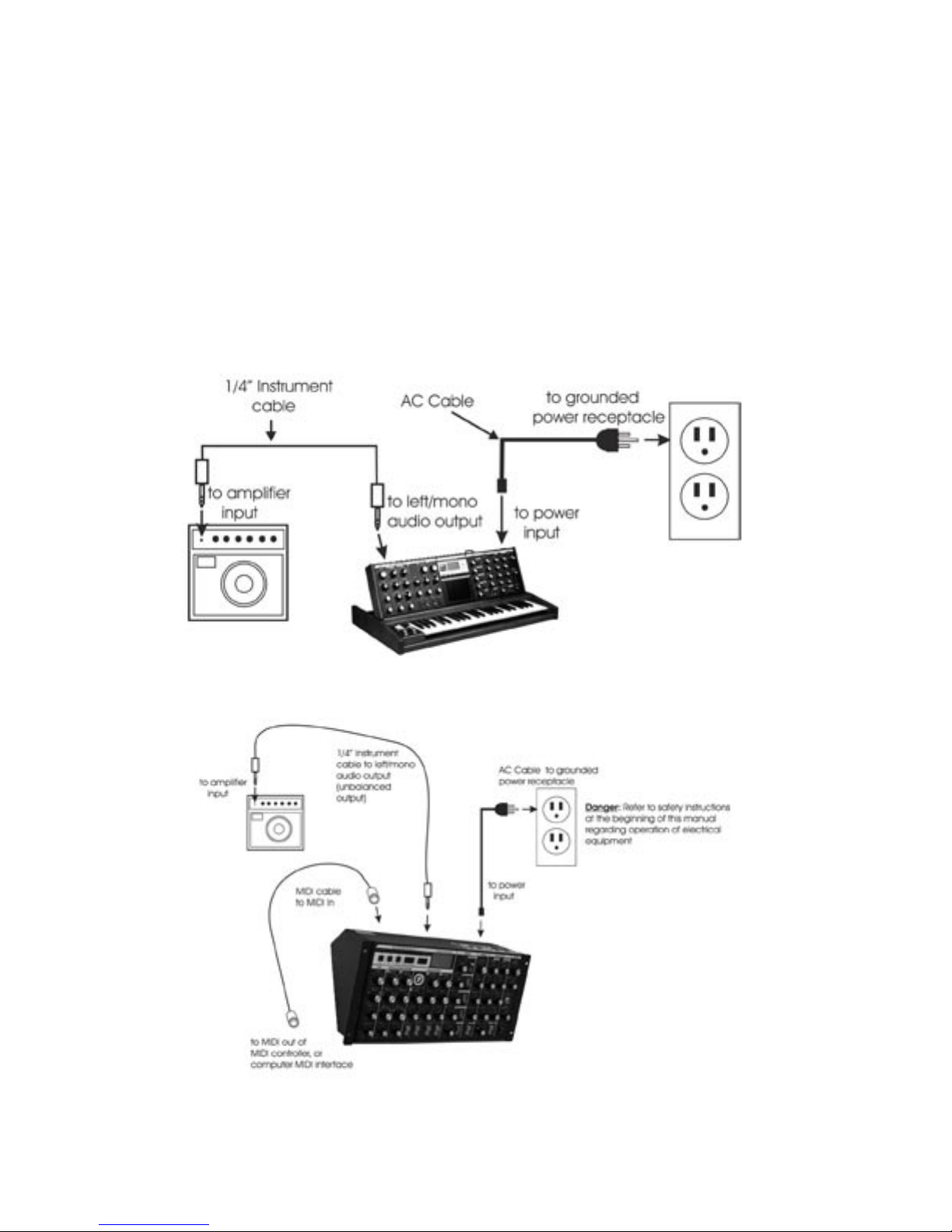
Connect to Power and Amplier
Make the connections as shown below. Connect the Voyger’s power receptacle (on the back panel) to
a wall outlet using the supplied AC power cord. The Voyager’s universal power supply will operate with
a power source from 90 to 250 Volts AC, 50/60Hz. Do not switch on the power yet. Set the Voyager’s
Master Volume control to minimum before making the connection to an amplier or headphones.
Page 6
Voyager User’s Manual - The Basics
Make your MIDI connections (RME only)
Connect the MIDI Out of the the MIDI device that will control the RME to the MIDI In of the RME. Note
that the RME’s MIDI channel default is Channel 1. This must match the MIDI channel of the MIDI device
controlling the RME.
Congure Output Mode Switch (RME Only)
If you are connecting the Voyager RME to an unbalanced input using 1/4” TS instrument cables, such as an
amplier combo, or a mixer’s unbalanced inputs, make sure the switch on the back of the RME’s panel is set
to “UNBAL.” When connecting to a balanced input using 3-conductor cables (TRS to TRS or TRS to XLR),
such as the balanced inputs on a mixer or powered monitors, set the switch on the back of the RME to
“600 Ω BAL.”
Making connections with the Voyager Keyboard
Making connections with the Voyager Rack Mount Edition
Page 7
Page 9
Voyager User’s Manual - The Basics
Voyager User’s Manual - The Basics
Now Power up
Turn the Voyager power ON. The LCD screen will light up and display a start-up message:
After a few seconds the start-up screen will disappear and the current preset will appear in the display. The
name of the current preset location (bank and preset number) will appear on the top line and the preset
name will be displayed on the middle line of the LCD screen:
Test for Sound and Set Levels
Play a few notes on the Voyager keyboard (or your MIDI controller if using the RME) while turning up the
volume of your amplication. Set the volume to a comfortable listening level.
Start Playing
Use the -1/+1 buttons to scroll through the presets. All preset locations are loaded with sounds from the
factory (128 presets each in 7 banks). There are a total of 896 locations in memory for presets – all are
user programmable. Note that once a preset is called up, you can tweak the parameters to your liking using
the front panel controls. Any changes made to the current preset will cause the display to change as shown,
with asterisks added to the preset name indicating that the preset has been modied:
If you make changes to a preset and want to return to the original sound, simply press ENTER. You can
toggle between the stored preset and the current edited preset by pressing the EDIT button and selecting
the COMPARE TO PRESET function. This function will allow you to toggle back and forth between the
original preset and the edited preset using the CURSOR button (for more on the COMPARE TO PRESET
function, see page 49). If you wish to save your changes, press EDIT and select the SAVE PRESET function
(for more on the SAVE PRESET function, see page 60). Any changes made to a preset will be lost if they
are not saved once you change to a new preset.
Page 8

Voyager User’s Manual - The Basics
Backlit Panel (applies to the Select Series, Electric Blue, and Rack Mount Editions only)
Check out the Backlit Panel! The Panel Brightness control knob is located on the far right side of the
keyboard on all Voyager keyboard editions, and in the lower right corner on the RME panel. This is the
intensity control for the Backlit Panel. When this knob is fully counter-clockwise, the panel light is OFF.
When the knob is fully clockwise the panel light is all the way ON. Moog Music recommends turning the
lamp OFF when not in use. See Appendix E for more information about the backlight lamp.
Making Your Own Sounds
To create your own sound from scratch, it’s good to start from the Voyager’s default parameters. This can
be done by the ‘Initializing Parameters’ command. Press the EDIT button, and press the +1 button until
INIT PARAMETERS is highlighted, then press ENTER. Use the CURSOR button to select ‘Yes’ and press
ENTER. This loads the default parameters temporarily into the current preset location. The default sound
is a basic one-oscillator square wave sound–think of it as a blank canvas for your sonic creations. Try the
controls to the right of the Mixer, one at a time, starting with FILTER CUTOFF, and notice how they affect
the sound. Then try combining different tones with the Mixer and Oscillators 2 and 3. Finally experiment
with the Mod Busses to see how different types of Modulation affect the sound.
To operate exclusively from the front panel and not from the presets, the ‘Real Panel Parameters’ must be
loaded. First initialize the parameters as described above. Then press the PANEL button twice. Use the -1
button to highlight ‘REAL PANEL PARAM’. Press ENTER, and you will see the prompt ‘Load actual panel
parameter? Yes/No’. Use the CURSOR to select Yes and press ENTER. The sound produced by the Voyager
is now determined by the settings of the front panel independently of preset memory.
When working with the Voyager, keep in mind that many of the controls are interactive, so there is
frequently more than one way to control a single parameter. This may be a source of confusion. For
instance, if the Sustain level of the Volume Envelope is all the way down, and the Attack and Decay times are
at zero, there will be no output. In another example, if you have a sound where the AMOUNT TO FILTER
control for the Filter Envelope is at zero, then changing the Filter Envelope ATTACK control will likely result
in no audible change. To use your Voyager to its fullest potential, it is very important to understand the
workings of all the controls and how they interact in order to understand how a sound (or lack thereof) is
produced. Don’t get frustrated, simply work systematically until you know what each control does and how
it works with the rest of the Voyager.
Installing the RME in an Equipment Rack
The Voyager RME comes with four 10-32 x ” oval head screws and four nish washers to be used to
secure the RME in an equipment rack. The RME occupies 5 standard rack spaces (8’). The angles of the
rear panel allow for standard ” plugs to be used for audio connections when rack mounted. A right angled
AC power connector is provided with the RME for installing it underneath a deep piece of rack-mounted
equipment. If the piece of gear that is to be above the RME is very deep, you will nd that it will be easier
to make the connections to the RME’s rear panel before installing it in the rack. When installing rackmounted gear, it is always best to install all four screws loosely before tightening any of the screws fully.
Page 9

Page 11
Voyager User’s Manual - The Basics
Voyager User’s Manual - The Basics
Using the RME as a Table-top Unit
The Voyager Rack Mount Edition is designed so it can be used as a table-top unit with the front panel
tilted at an angle that is very convenient for tweaking. If your primar y use of the RME is as a table-top
unit, we highly recommend the purchase of the optional wood handles (Moog P/N VY-WOD-01). They
are functional, look really sharp (giving that vintage Moog vibe), and are available from moogmusic.com, or
authorized Moog Voyager dealers.
Warranty registration
Moog’s on-line warranty registration system is the best way to activate your warranty. Access the Moog
web site at www.moogmusic.com and click on the “Product Register” tab. If you complete all the requested
information, Moog Music will send you a complimentary gift.
The Voyager is recommended for an operating temperature between about 50 and 100 degrees
Fahrenheit. It is safe to operate the synthesizer outside of this range (between 0 and 125 degrees F), but the Voyager’s voltage controlled oscilators (VCOs) may not remain in tune.
It is recommended that a warm up period of about 15 minutes be allowed before using the
Voyager. This warm-up period is necessary for the proper operation of the VCO’s (the warm
up period may be longer if the Voyager has been stored outside the recommended operating
temperture range).
Page 10
Voyager User’s Manual - The Basics
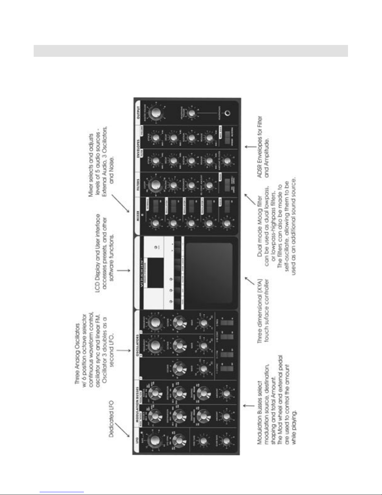
Overview and Features
The Voyager is a monophonic analog synthesizer that is a descendant of the classic Minimoog. Its sound
sources are an external audio input, a noise source, and three analog, variable waveform oscillators. The
Voyager has front panel controls for real time control of its parameters (Voyager keyboard edition shown).
Page 11
Page 13
Voyager User’s Manual - The Basics
Voyager User’s Manual - The Basics
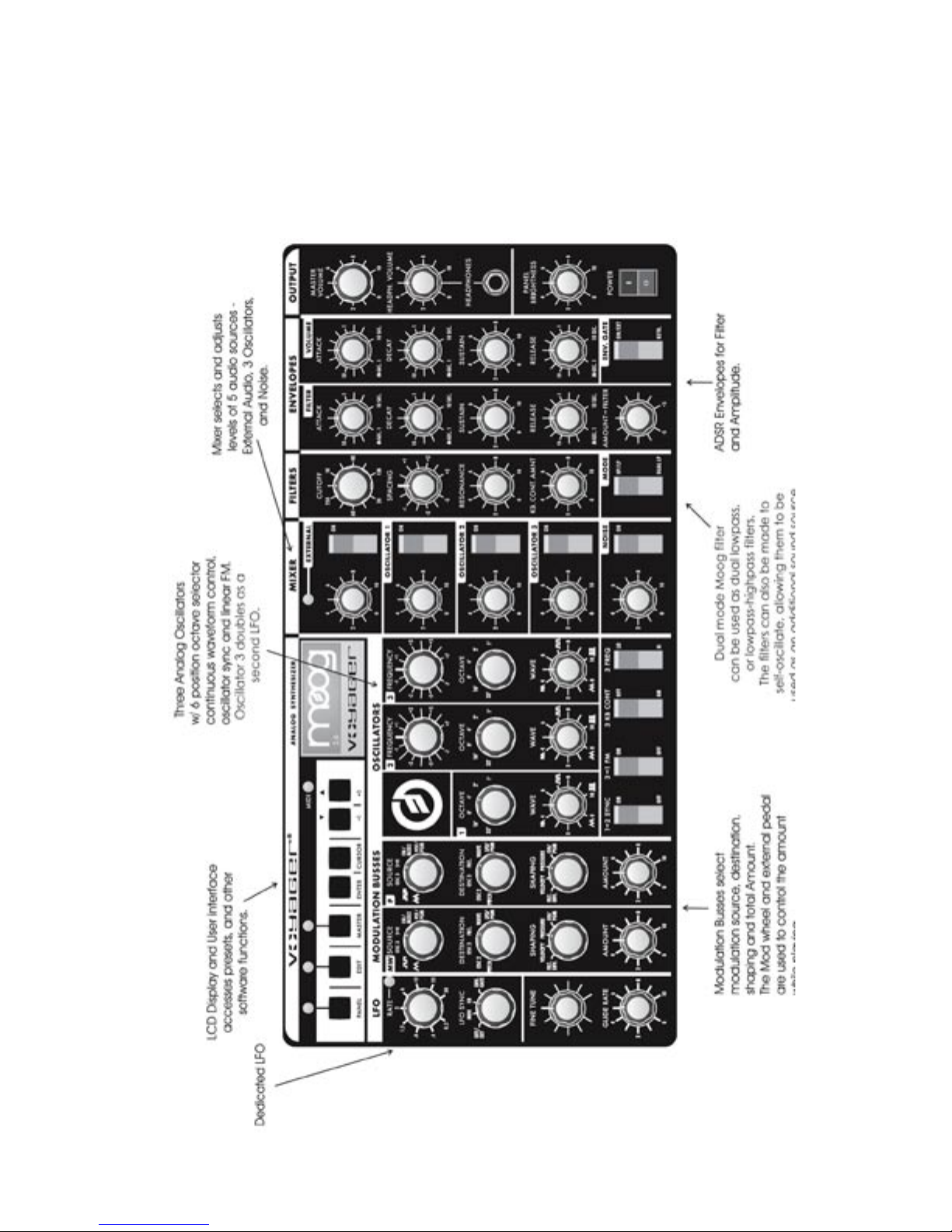
RME Front Panel
The RME offers the same front panel controls as Voyager Keyboard Editions., and is nearly identical in its
layout, save for the Touch Surface (not offered on the RME) and a repositioned User Interface/LED Display.
Page 12
Voyager User’s Manual - The Basics
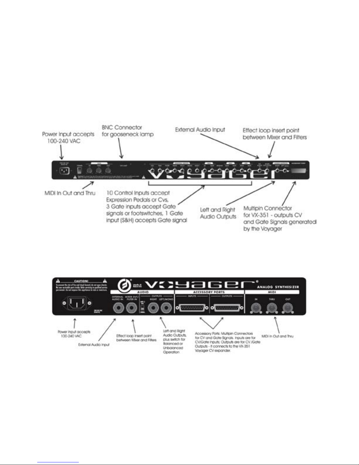
Back Panel:
The Voyager’s back panel offers connections for Power, MIDI, Control Voltage I/O and Audio I/O. For Voyager Keyboards, 14 CV inputs are provided on “ jacks. A jack with a red nut indicates a CV/Expression Pedal
input, while a jack with a blue nut indicates a gate/footswitch input. CV outputs are provided on a 25-pin accessory port. On the RME, CV input and output connections are provided on two 25-pin accessory ports.
Back Panel of Voyager Keyboard Editions
Back Panel of Voyager Rack Mount Edition
Page 13
Page 15
Voyager User’s Manual - The Basics
Voyager User’s Manual - The Basics
Signal Flow
To understand the Voyager’s internal signal ow, it’s helpful to consider the three types of signal routings
in the system: the audio path, the control voltage path, and the modulation path.
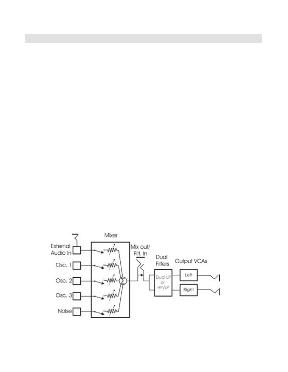
Audio Path
The Voyager’s audio path includes all of the signal sources and signal modiers that produce an audio
output. These include the oscillators, mixer, lters and ampliers (VCAs).
The Oscillator section includes controls for selecting the octave and waveforms, adjusting the tuning of
the second and third oscillators, for setting the oscillator sync and linear FM functions, and for setting the
frequency range and keyboard control for Oscillator 3.
The Mixer section is where the oscillators and other sound sources (noise and external input) are
selected and mixed together. The output of the Mixer section is routed to the Filter section through a
Mixer Out/Filter In jack on the Voyager’s rear panel. This jack allows you to interrupt the signal routing
between the Mixer and Filter to insert an external effect, or take the output of the Mixer directly.
The Filter section is responsible for altering the harmonic content of the combined sound sources. The
Voyager’s Filter section contains two lters that work together in two different modes.: Dual LP and
HP/LP. Dual LP mode features two lowpass lters in parallel, while HP/LP (Highpass-Lowpass) mode
features a lowpass and highpass lter in series, creating a Bandpass lter response. In either mode,the
Filter Cutoff control affects the cutoff frequency of both lters, and the Spacing control is used to adjust
the difference between the cutoff frequencies. The outputs of the lters are routed to the Voltage
Controlled Ampliers (VCAs).
The VCAs shape the volume level of the audio signal using time-varying control signals called Envelopes.
The Envelopes section (part of the control voltage path) contains one Envelope Generator to control
the Filters, and one Envelope Generator to control the VCAs. The Voyager’s audio path is illustrated
below.
Page 14
The Voyager’s Audio Path
Voyager User’s Manual - The Basics
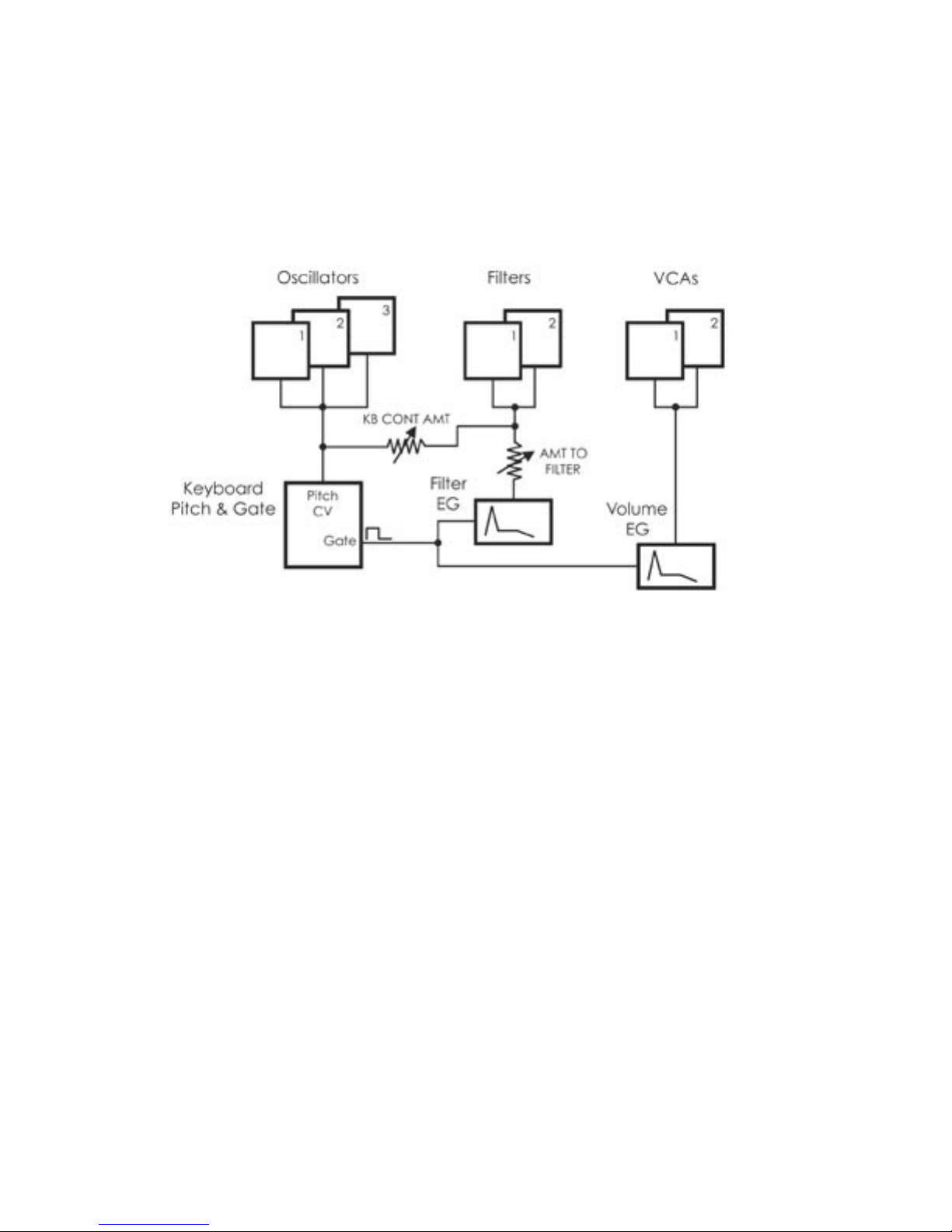
Control Voltage Path
When a key is pressed, or a MIDI Note On message is received, a Gate and Pitch Control Voltage (CV) are
produced. The Gate signal is used to trigger both the Filter and Volume Envelope Generators (EGs). The
Pitch CV is used to determine the pitch of the Oscillators and can be applied to a varying degree to the
Filters through the Keyboard Control Amount knob. The basic control voltage path is illustrated below.
The Voyager’s Control Voltage Path
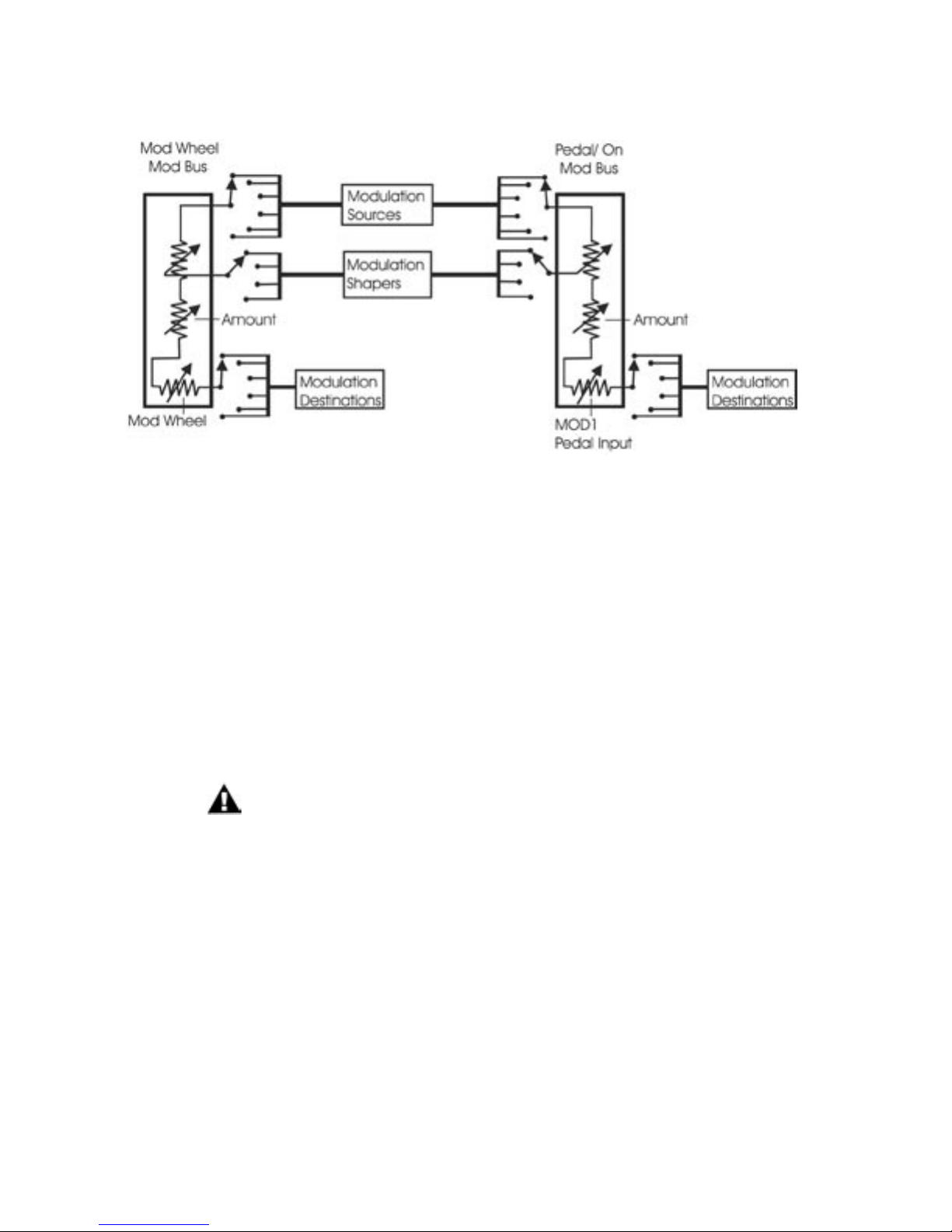
Modulation Path
Modulation is performed through the Modulation Busses. There are two separate Mod busses. One is
controlled by the Mod Wheel, while the other is controlled by the MOD1 CV, which is a CV input on the
back panel. The MOD 1 CV input is normalled to +5V, so with nothing plugged into this jack, the PEDAL/
ON bus is on at the level determined by the PEDAL/ON Amount control. In each Mod Bus, a Modulation
Source, Shaping signal and Destination are selected. An overall maximum modulation amount can be set
with the Amount control. The Modulation Buss routing is illustrated in the gure on the next page.
The Voyager’s Low Frequency Oscillator (LFO) is assigned through the Modulation Busses. The LFO features
a triangle and a square wave, and both waves can be used at the same time. The LFO is also used to trigger
the Sample and Hold circuit, which means the speed of the Sample and Hold is adjusted by the LFO RATE
control.
Page 15
Page 17
Voyager User’s Manual - The Basics
Voyager User’s Manual - The Basics
The Modulation Buss Path
Additional Modulation
The Touch Surface controller can control three parameters simultaneously. The position of a nger on the
touch pad generates a control voltage for the horizontal (X) position and a contorl voltage for the vertical
(Y) position. Pressing on the touch surface generates a control voltage based on the area (A) of the ngertip. A light touch causes less of your ngertip to touch the pad, while a heavy touch causes more contact
with the touch surface. Touch Surface Controller parameters (X & Y) are available as Modulation Sources
for both the Mod Wheel and Pedal/On busses through Edit Mode programming (See Edit Mode 2.1 & 2.3 ‘PGM M-WHL SOURCE’ and ‘PGM PEDAL SOURCE’). The four Touch Surface parameters (X, Y, A & Gate)
can also be programmed as modulation destinations through Edit Mode programming (see Edit Mode 5.1
- ‘T.S DESTINATIONS’).
Although the RME has no Touch Surface Controller, the TOUCH inputs on the
VX-352 RME CV Expander can be programmed just like the outputs of the Touch
Surface on the keyboard Voyager.
Digital Features
The Voyager has three operation modes: Panel, Edit, and Master. Panel Mode is used for accessing and
performing with the Voyager’s 7 banks of 128 user-writable presets (896 presets total). Panel Mode has
a menu that can be accessed for performance related functions such as “parameter display” which shows
stored and edited values as you edit a preset. Edit Mode contains all Voyager functions that can be stored in
a preset that are not set by the front panel controls, such as naming presets, and some advanced functions
like Pot Mapping, or Filter Poles. Master Mode is used for global settings, such as MIDI In and Out channels.
Page 16

Voyager User’s Manual - The Basics
Digital Features (con’t)
The Voyager preset is basically a “snapshot” of front panel settings combined with the parameters set in
Edit Mode. The preset that is loaded is referred to as the “Current Panel Preset” and is stored in a memory
buffer separate from the presets. This preset can be edited freely. The parameters are set by the Voyager’s
preset memory until a setting is changed, at which time the current position of that control takes over. The
Voyager has both a ‘Compare’, and ‘Recall Last Edit’ sound function. Changes to a preset can be saved to
any of the 896 preset locations using the Edit Mode function ‘Save Preset’. There are three ways to change
Presets:
1. Use the -1/+1 buttons. Note that if QUICK MODE is turned OFF, the ENTER button must also
be pressed to load the new preset (for more on QUICK MODE, see page 44).
2. When the External Audio On/Off switch is OFF, the EXTERNAL level control can be used to
scroll through the entire current bank. When the desired preset is reached, pressing the
ENTER button will load the new preset.
3. The Voyager responds to MIDI Bank Select and Program Change messages.
For storage and recall of more than 896 presets, Moog Music recommends purchasing the Voyager Editor/
Librarian, a Mac/PC program designed for creating, organizing and archiving presets for the Voyager. It can
be purchased from the Moog Music website (www.moogmusic.com).
The Voyager has a full MIDI implementation. Its front panel rotary controls and switches send MIDI CCs,
and the Voyager’s synth engine receives and responds to these same commands. Presets can be sent as
SysEx data to a computer for storage, and the Voyager can receive SysEx data either for single presets,
preset banks, or for operating system updates.
Multiple Voyagers (up to 16) can be connected to function as a polyphonic system. The Master Mode
function ‘MIDI Key Order’ assigns each Voyager to be a voice within the system, the size of which can be set
by the user.
The Moog Little Phatty synthesizer can also be used in a Voyager polyphonic
system. For more information, consult the LP User’s Manual.
Page 17
Page 19
Voyager User’s Manual - The Components
Voyager User’s Manual - The Components
The Components
Now let’s take a look at the individual module components that make up the Voyager Synthesizer, starting with
the Mixer section. Then we’ll move on to the Oscillators, Filters, Envelopes, and Output Sections, the LFO and
Modulation sections, the Keyboard and Left-Hand controls, the Back Panel, and the User Interface section.
For each section, illustrations of both the the Voyager Keyboard and Voyager RME front panels will be shown.
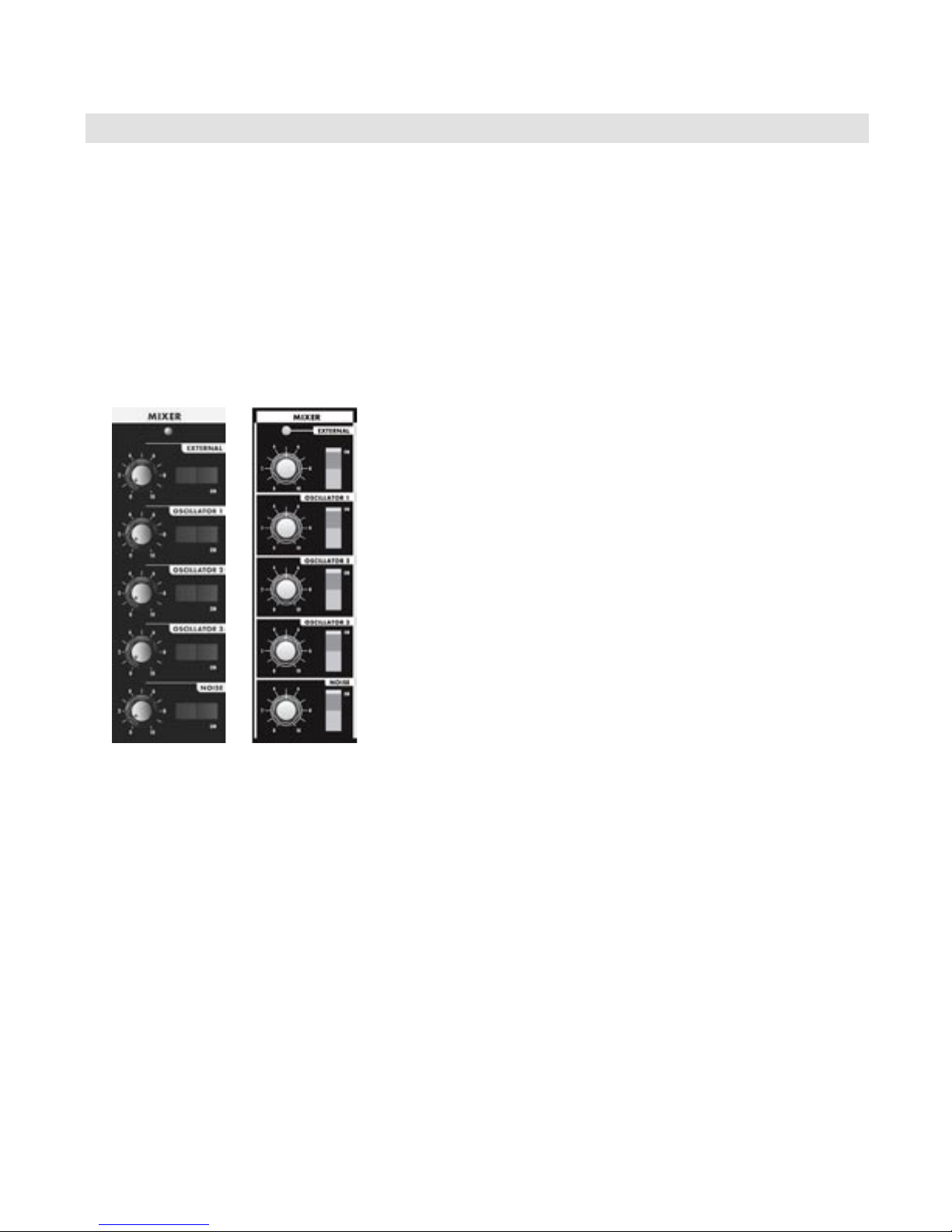
A. The Mixer Section
The Mixer combines the main sound sources of the Voyager. It’s a good place to start when creating a new
sound from scratch, or guring out how a sound is put together. All ve of the Voyager’s sound sources can be
swicthed ON or OFF, and their levels can be individually adjusted.
The ve sound sources are:
- External Audio Input
- Oscillator 1
- Oscillator 2
- Oscillator 3
- Noise Source
Each sound source in the Mixer has a dedicated ON/OFF switch and
a level control.
The audio output of the Mixer is routed to the Filter through an
insert jack on the Voyager’s back panel. If an insert cable is plugged
into this jack however, the Mixer output be be routed through an
external effect and returned back into the Voyager’s signal path. This
jack can also be used as direct output of the Mixer if desired (see
page 14 for more information).
Voyager
Keyboard
Voyager
RME
Mixer Section Controls:
Oscillator 1, 2 & 3:
The OSCILLATOR controls in the Mixer allow each oscillator to be switched ON or OFF , and mixed in any
proportion. When the levels of the oscillators are set high, the output from the Mixer gently overdrives the
Filter section. This was one of the impor tant features in the original minimoog that gave it its characteristic
“fat” sound.
Noise:
The NOISE control is used to mix noise with the other sound sources. In the Voyager, noise is a white/pink
hybrid. It is useful for making ocean wave sounds, explosions, wide sounds, or adding subtle coloration to a
sound.
Page 18
Voyager User’s Manual - The Components
External:
The EXTERNAL control allows an external monophonic audio source to be routed into the Mixer, where
it can be mixed with the Oscillators and Noise source (an “Ext Audio In” jack on the Voyager back panel is
provided for this input). The LED above the EXTERNAL control knob begins to light up as the input signal
overdrives the Mixer input. When the light is faint, a small amount of soft clipping is occurring. When the
LED is bright, the signal is strongly overdriven. Judicious use of overdrive can really fatten up a sound. The
External Audio Input can accept a signal from instrument level to line level.
A secondary function of the EXTERNAL control knob is that it can be used to scroll through a
bank of presets when in PANEL mode when the EXTERNAL switch is set to OFF.
You can use the External Audio Input jack to route the Voyager output back into itself. This
classic feedback trick is a great way to produce a thicker, meatier sound when the gain is
properly set with the EXTERNAL control knob.
Mixer Back Panel Connections:
Mix-Out Loop:
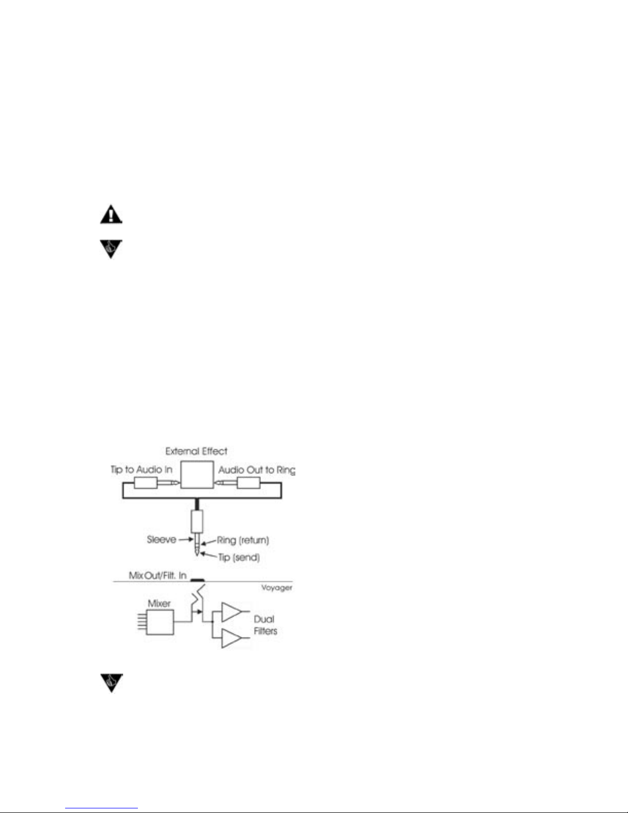
The jack on the back labeled “Mix Out/Filter In” is an insert point between the Mixer output and the Filter
input. Using a standard inser t cable, an effect such as a moogerfooger® MF-102 Ring Modulator can be
inserted to add effects to the oscillator, noise source, and external audio in prior to the Filter stage. The
Mixer output signal appears at the tip of the insert cable jack as shown below. The return signal is applied
to the ring of the jack. A cable fully plugged into the jack breaks the connection between the Mixer and the
Filter, and unless the Return signal is sent to the ring of the jack, no signal will pass through to the Filter. The
level settings in the Mixer affect the output level, so keep this in mind as you try different devices in this loop.
Got a few guitar stompboxes laying around? The Mix-Out loop allows you to easily insert guitar
pedal effects into the Voyager’s signal path. What to try? Nearly any type of sound effects
device or sound modier is fair game (chorus, phaser, anger, overdrive, distortion, graphic/
parametric EQ, tube preamp, exciter, etc.) and worth checking out. As always, experimentation
is encouraged!
Page 19
The Mix-Out loop adds tremendous
exibility to the powerful sound
creation abilities of the Voyager!
Page 21
Voyager User’s Manual - The Components
Voyager User’s Manual - The Components
B. The Oscillator Section
The Oscillators are the main sound source of the Voyager. The oscillators in the Voyager are all analog
Voltage Controlled Oscillators, or VCOs. They feature a temperature regulation circuit that provides them
with excellent tuning stability. The VCOs can produce a total musical range of 8 octaves! In addition, the
frequency of oscillator 3 can be set to the sub-audio range (<20Hz) for use as a second LFO.
Voyager
Keyboard
Voyager
RME
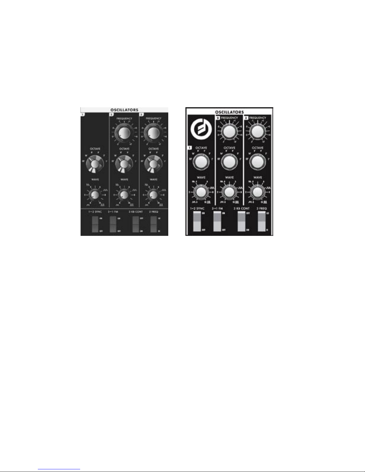
Oscillator 1 performs as a master oscillator to which Oscillator 2 and 3 are tuned. The timbres of the
oscillators are adjusted by their variable Waveform controls. In addition, there are switches for Oscillator
2 sync to 1; linear frequency modulation of Oscillator 1 by 3; Oscillator 3 keyboard control on/off; and
Oscillator 3 Lo or Hi frequency range. The frequencies of the Oscillators are controlled by a number of
sources. The main source is the pitch CV generated by keyboard or by MIDI Note ONs. A glide circuit can
be switched in between the Keyboard CV and the oscillators to slow the voltage changes between notes,
resulting in a glissando effect. The Keyboard CV then is mixed with the Octave switch CV, the Frequency
control (Oscillators 2 and 3), the Pitch Bend Wheel, the Fine Tune control, and the output of the Mod
Busses when the ‘Pitch’ destination is selected.
Oscillator Section Controls:
Octave:
Each Oscillator has a 6-position OCTAVE switch that selects the relative frequency range. To hear how it
works, turn off Oscillators 2 and 3 in the Mixer. Turn Oscillator 1 on and set its level to 5. Play a note on
the keyboard and rotate the Oscillator 1 octave switch clockwise one click – the note will rise an octave.
You can use this control to change the frequency range that the keyboard controls. The panel markings 32’
up to 1’ are octave standards based on organ stops. On the 16’ setting, MIDI Note number 93 is A440
(equivalent to the “A” key above middle C) .
Page 20
Voyager User’s Manual - The Components
Frequency:
Oscillators 2 and 3 have a FREQUENCY control. When the control is in the center position, the oscillators
should be in unison with the frequency of Oscillator 1 (when the octave switches for all three oscillators
are in the same position). The Frequency control can change the pitch of Oscillator 2 or 3 a total of +/- 7
semitones relative to Oscillator 1. This allows more than one frequency to be played when a key is pressed.
Adjusting the frequency of Oscillator 2 & 3 to be slightly out of tune with Oscillator 1 results in the classic
“oscillator beating” chorus sound.
The Oscillator FREQUENCY controls have no calibration - sometimes unisons are made
with the controls a little left or right of center. Oscillator 1 does not have a Frequency control
because it is designed to serve as a reference oscillator for the other 2 oscillators.
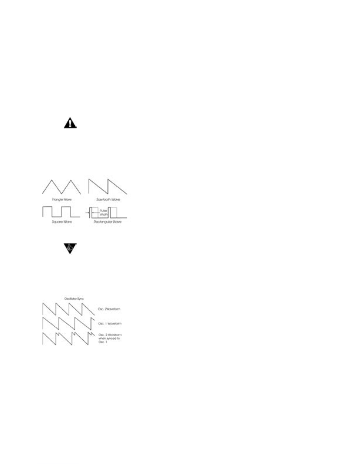
Wave:
Each oscillator features a continuously variable WAVE (waveform) control. The legend on the front panel
shows the pure waveforms that are available. They are triangle, sawtooth, square, and rectangular. The
waveform is morphed gradually from one to another as the waveform control is rotated. Because the
waveform is voltage controlled, this parameter can be modulated;
this generates some very interesting timbral changes. By limiting the
modulation between the square and skinny pulse waveform, you
can get pulse width modulation. Although the waveforms can be
set from the front panel individually for each oscillator, modulation
through the Mod Busses is applied to all three waveform controls
simultaneously. When using modulation, it is possible to make the
width of the rectangular wave so skinny that it becomes silent.
Several factory presets illustrate the use of extreme modulation to force the rectangular
wave to silence. Examples include “Waveform Dance” (preset 23 in the C bank, and “Relaxation Drone” (preset 89 in the D bank).
1-2 Sync:
The 1-2 SYNC switch is one of four switches located at the bottom of the oscillator panel. In the ON
postion, the 1-2 SYNC switch synchronizes Oscillator 2 to Oscillator 1. Oscillator sync is an effect caused
by resetting an oscillator waveform’s start point with another
oscillator as shown here (the effect is more noticeable if the synced
oscillator is a higher frequency than the reset oscillator). The main
frequency heard is that of the reset oscillator. As the frequency of
the synced oscillator is swept, it reinforces the harmonics of the
reset oscillator. Depending on how it is applied, the effect can be
aggressive or warm and vocal. This effect is much more dramatic
when Oscillator 2 is set to a higher octave than Oscillator 1.
3-1 FM:
In the ON position, the 3-1 FM switch establishes direct linear Frequency Modulation (FM) of Oscillator
1 by Oscillator 3. When an Oscillator is used as a CV source for another VCO, it is called frequency
modulation. Frequency modulation effects can vary from vibrato or trill effects to clangorous inharmonic
sounds to rich timbres that evoke acoustic sounds. Linear FM is the kind of frequency modulation used in
classic FM synths.
Page 21
Page 23
Voyager User’s Manual - The Components
Voyager User’s Manual - The Components
3 KB Cont (Oscillator 3 Keyboard Control):
The 3 KB CONT switch disables keyboard control of Oscillator 3 when in the OFF position. By disabling
the keyboard control, you can use Oscillator 3 as a drone or as a modulation source whose frequency
doesn’t change with the key played. In addition to turning off the keyboard control of Oscillator 3, switching
to OFF increases the amount by which the Oscillator FREQUENCY control changes Oscillator 3’s
frequency.
3 Freq (Oscillator 3 Frequency):
The 3 FREQ switch selects Oscillator 3’s frequency range. When the switch is in the LO position, Oscillator
3 operates as a subaudio sound source (producing clicks) or as a modulation source (LFO). When the
swicth is in the HI position, Oscillator 3 operates with the same available frequency range as Oscillator 2.
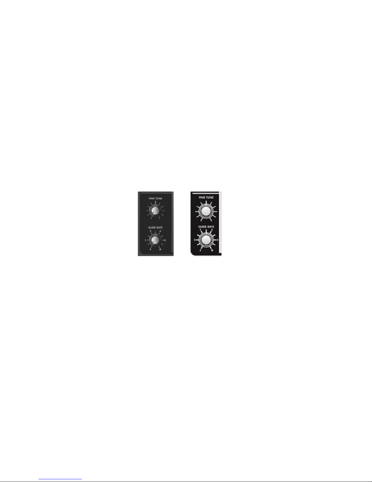
Related Oscillator Controls:
Two other panel controls interact with the Voyager Oscillators: Fine Tune and Glide. These controls are
located in the lower left of the Voyager’s front panel
Voyager
Keyboard
Voyager
RME
Fine Tune:
The FINE TUNE control is used to tune the Voyager’s oscillators +/ – 2 semitones for matching an external
reference pitch.
Glide Rate:
Glide enables a glissando effect between notes. The GLIDE RATE control adjusts the rate of the glissando.
The glide rate can vary from a very fast to a very slow glide. It can be switched on or off using the GLIDE
switch in the Voyager keyboard left-hand controller section, or in the PANEL mode menu of the RME. You
can also turn glide on or off by sending a MIDI CC 65 message (0-63 = off, 64-127 = on).
Page 22

Voyager User’s Manual - The Components
Additional CV Connections (applies to all Voyager keyboards and the RME with the VX-352 CV Input Expander only):
Pitch:
The PITCH jack allows you to connect an external CV or expression pedal to control the Voyager’s pitch.
All three oscillators are effected by this connection. The effective input range is -5 to +5 V, where a positive
CV will add to the oscillator dial settings, and a negative CV will subtract from the settings. If an expression
pedal is plugged in, the pitch can only be made to increase since the pedal connection supplies only a positive voltage.
Wave:
The WAVE jack allows you to connect an external CV or expression pedal to control the oscillator wave-
forms. All three oscillators are effected by this connection. The effective input range is 0 to +5 V; the result
is dependant upon the panel WAVE control knob setting (a positive CV will add to the WAVE control
knob).
On the Voyager keyboard back panel, PITCH and WAVE are two of 14 jacks that are color-coded
with either red or blue nuts. A red nut indicates an input for either a CV or Expression Pedal,
while a blue nut indicates an input for either a Gate signal or a footswitch. All red jacks are the
TRS type, supplying +5V on the ring, and applying the input CV or variable pedal voltage return
on the tip. Color-coding is not used on the VX-352 CV Input Expander. Instead, CV/Expression
pedal input jacks are indicated by a white circle around the jack, while Gate/footswitch inputs are
marked with arrows on the sides. For more on the VX-352 CV Input Expander, see Appendix H.
Page 23
Page 25
Voyager User’s Manual - The Components
Voyager User’s Manual - The Components
C – The Filter Section
Filters are used to adjust the tone color of an audio signal. Filters modify sounds by rejecting some
frequencies while allowing others to pass through. To understand the operation of lters and how they
process sound, there are a few important terms to know.
The rst term is ‘Cutoff Frequency’. The cutoff frequency is the point
at which an audio signal’s frequencies begin to be rejected. Then there
are the different types of lters; some of the most common and most
musically useful lter types are ‘lowpass’, ‘highpass’, and ‘bandpass’. A
lowpass lter behaves as its name indicates; it passes all frequencies
below the cutoff frequency and rejects frequencies above the cutoff. A
highpass lter does the opposite. It passes all frequencies above the
cutoff point and rejects the frequencies below the cutoff. A bandpass
lter does a bit of both, since it is created by combining lowpass and
highpass lters. In the case of a bandpass lter, the lowpass section
denes the maximum frequency that will pass through, while the
highpass section denes the minimum frequency that will pass through.
What’s left is a band of frequencies that will pass through the lters
unaffected, hence the name, bandpass.
Another key term is the ‘Cutoff Slope’. The cutoff slope determines
the amount of attenuation that occurs above the cutoff frequency.
Voyager
Keyboard
Voyager
RME
The cutoff slope is specied in decibels per octave (commonly
written as ‘dB/oct’). The electrical design of a lter determines the
cutoff slope. You may have heard the term ‘pole’ as it refers to lters.
A pole is simply a design aspect of a lter, and each pole in a lter
typically adds 6dB to the cutoff slope. This means that a one-pole lter has a cutoff slope of 6db/oct, a
2-pole lter has a 12dB/oct cutoff slope, etc. The classic Moog lter – the sound that started it all – is a
4-pole, 24dB/oct lowpass lter.
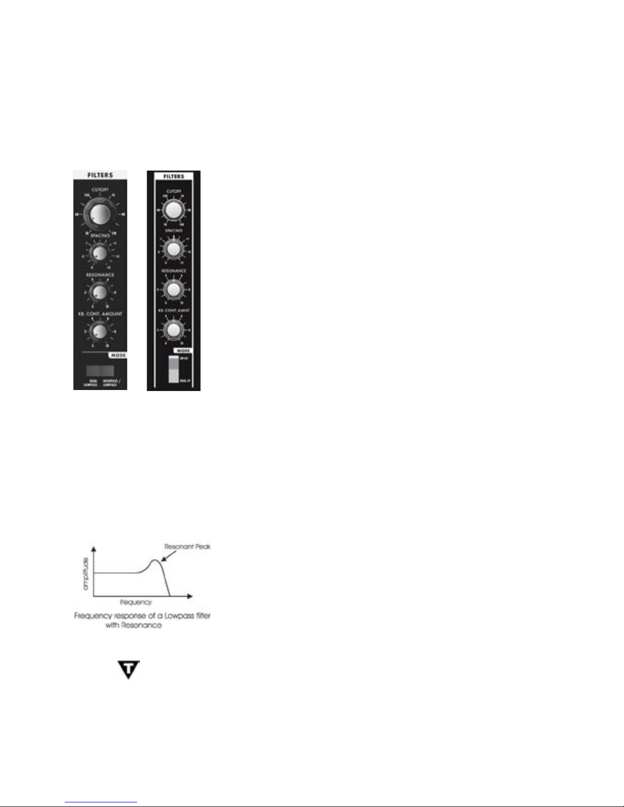
The nal lter term to dene is ‘Resonance’. Resonance refers to a peak that appears at the cutoff
frequency. In synthesizers, this resonant peak is usually an adjustable parameter (called ‘ Resonance’ ) that
is part of the lter controls. High resonance values emphasize the overtones that fall within the frequency
range of the resonant peak, givng the processed sound a character that
can be described as vocal, quacky or zappy, depending on the source
sound. When the resonance is turned up past about 8 on the dial, the
lter begins to self-oscillate at the cutoff frequency, producing a sine
wave tone. The Keyboard Control Amount control sets how much the
lters’ cutoff frequencies track the keyboard note that is played. As you
play higher on the keyboard, the cutoff frequency goes higher, too.
In the original Minimoog, the Resonance control was called ‘Emphasis’. Many of the
current Minimoog emulations (both hardware and software) use the term ‘Emphasis’
instead of ‘Resonance’ in the lter section to preserve the authentic vibe of the
original hardware.
Page 24
Voyager User’s Manual - The Components
The Voyager has two voltage controlled lters (VCF’s) that can be congured either as dual lowpass lters
or as a combination of highpass & lowpass through a front panel switch. Additionally, the cutoff slope of
each lter can be changed in software, resulting in a wide range of unique and interesting sounds.
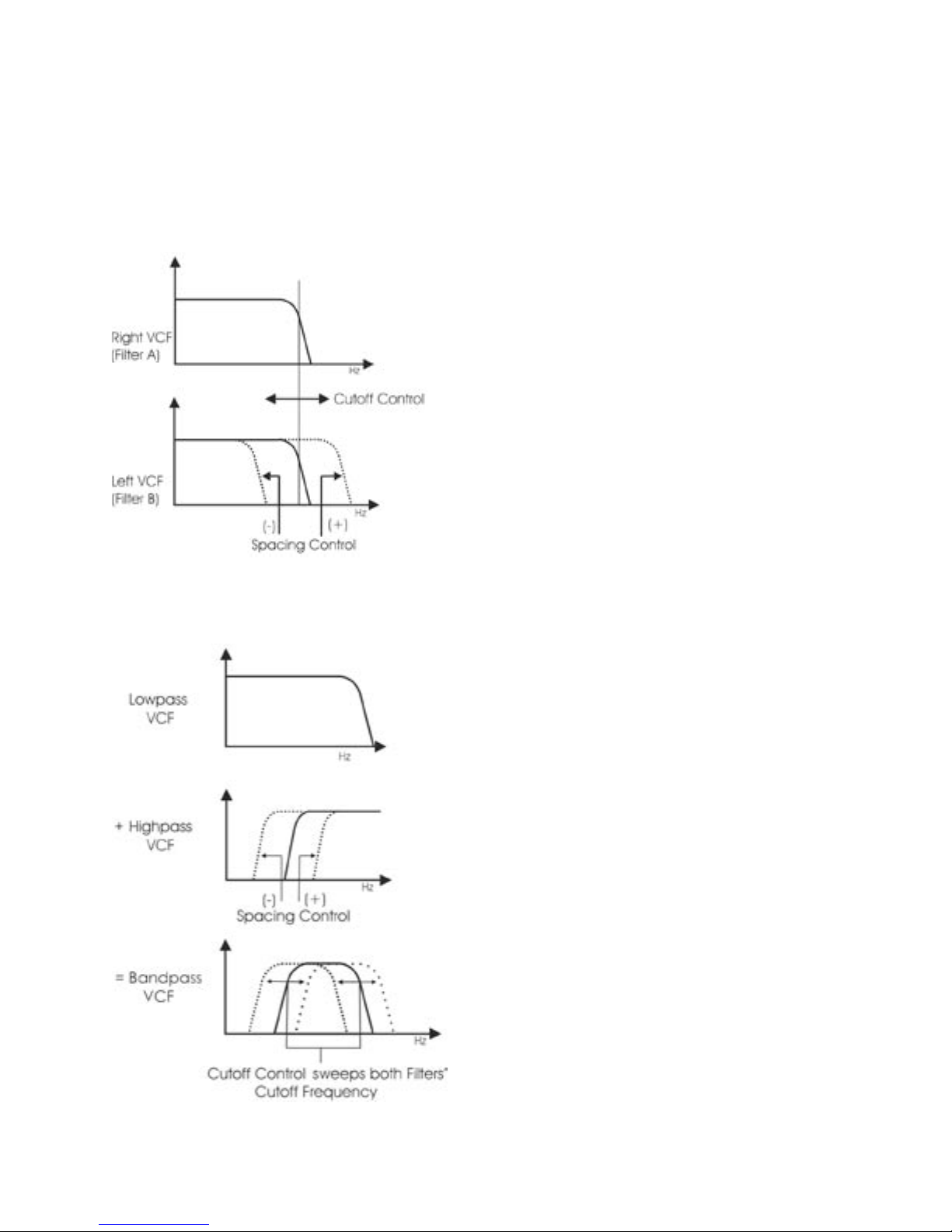
Dual Lowpass Mode:
The Voyager’s Dual Lowpass lter mode features two
lowpass lters which are routed to the left and right
audio output, creating a stereo effect. The CUTOFF
knob controls the frequency cutoff of both lters.
The lters can be set to the same cutoff frequency,
or adjusted to different cutoff frequencies using the
SPACING control. When the two lters are set at
different cutoff frequencies and routed to two different
speakers, what you hear can be a fantastically swirly
and vocal sound – similar to a phaser effect. In Dual
Lowpass mode, the RESONANCE control affects both
lters identically.
Highpass Lowpass Mode:
In Highpass/Lowpass mode, the Voyager’s lters are
congured as a lowpass and highpass lter in series,
resulting in a bandpass lter. The output of the
bandpass lter is routed to both outputs. As with the
Dual Lowpass mode, the CUTOFF control changes
the cutoff frequency of both lters, and the SPACING
control sets the frequency difference between the
highpass lter and lowpass lter. The spacing between
the two lters creates a variable passband. In this mode,
the RESONANCE control affects only the lowpass lter,
thus making for some distinctive and ususal lter sounds.
Page 25

Page 27
Voyager User’s Manual - The Components
Voyager User’s Manual - The Components
Filter Section Controls:
Cutoff:
The CUTOFF knob is the main lter control. This sets the cutoff frequency of both of the lters in the both
Dual Lowpass and Highpass/Lowpass mode.
In Dual Lowpass mode, the frequencies to the right of the indicator on the knob are the frequencies that
are ltered out. The frequencies to the left of the indicator are the frequencies that are allowed to pass
through the lter. This is why as you turn the control clockwise the cutoff frequency becomes higher and
the sound becomes brighter. Of course to hear the effect of a lowpass lter it helps to have a signal rich
in harmonics which provides high frequencies to lter. A good example of a sound rich in harmonics is a
sawtooth waveform.
In Highpass/ Lowpass mode, the combination of highpass and lowpass lters forms a bandpass lter. The
CUTOFF control changes the center frequency of the passband.
Spacing:
The SPACING control is used to determine the difference between the cutoff frequencies of the two lters
in both Dual Lowpass mode and Highpass/ Lowpass mode. The numbers on the legend around the knob
refer to octaves. When the SPACING control is centered, the cutoff frequencies of the two lters are
identical and the lter sounds like a classic Moog Filter. Setting the SPACING control to +1 in Dual Lowpass
mode means that the right lter has a cutoff frequency equal to where the CUTOFF control knob is set,
and the left frequency has a cutoff frequency that is one octave higher than the right lter. This means when
the CUTOFF control is swept, two resonant peaks are heard, giving the lter a unique quality.
In Highpass/Lowpass mode, the SPACING control sets the difference between the cutoff frequencies by
shifting the highpass lter’s cutoff frequency up or down. When the SPACING control is fully clockwise, the
cutoff frequencies of the two lters are the same, making for a very narrow bandpass lter.
Resonance:
The RESONANCE control causes feedback in the lter circuit that adds harmonic emphasis at the cutoff
frequency. This control affects the lowpass lters in either lter mode, but not the highpass lter. When the
RESONANCE control is all the way down, the lowpass lters act as a tone control, rolling off high end as
the CUTOFF control is turned down. As the resonance increases, the lter begins to form a peak at the
cutoff frequency. Harmonic content within the frequency range of this resonant peak is emphasized, and the
sound takes on a vocal-like quality. As the RESONANCE control is turned up the peak increases in strength
until the control is set to 8 or higher, when the lter begins to self-oscillate – creating sine waves with the
same frequency as the cutoff frequency.
Keyboard Control Amount:
The KEYBOARD CONTROL AMOUNT knob allows the lter cutoff to follow the key played on the
Voyager keyboard (or the keyboard controlling the Voyager RME). A higher key will cause a higher cutoff
frequency. This allows a sound to retain its brightness as it is played higher on the keyboard.
Mode:
The lter MODE switch selects either the dual lowpass conguration (DUAL LP) or the highpass/lowpass
conguration (HP/LP).
Page 26
Voyager User’s Manual - The Components
Additional CV Connections (applies to all Voyager keyboards and the RME with the VX-352 CV Input Expander only):
Filter:
The FILTER jack allows you to connect an external CV or expression pedal to control the lter cutoff
frequency. Both lters are effected by this connection, regardless of the lter mode setting. The effective
input range is -5 to +5 V, where a positive CV will add to the lter cutoff dial setting, and a negative CV will
subtract from the setting. Note that if an expression pedal is plugged into this jack, the cutoff can only be
made to increase from the cutoff dial setting since the pedal connection supplies only a positive voltage.
D. The Envelopes Section
Musical sounds have a start, middle and an end. For example, a plucked string sound starts with an initial
burst of energy and then slowly fades out until it is silent. In synthesis terms, this progression is called an
envelope – a shape that denes the changes that occur in a sound over time. An envelope can dene any
aspect of change in a sound – volume, timbre, or pitch. The circuits that create envelope control signals in
synthesizers are called Envelope Generators (EGs).
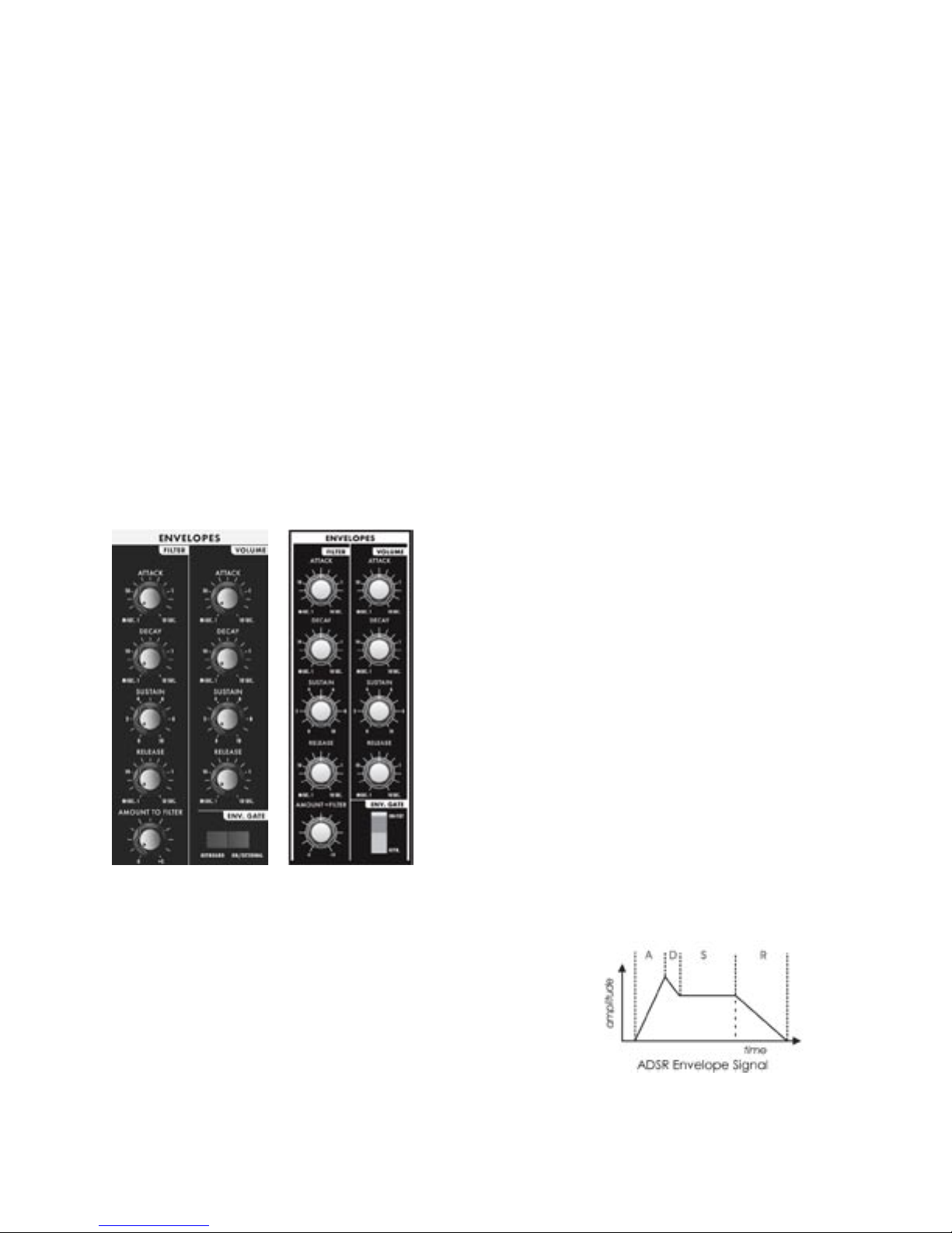
When triggered, EG’s produce a time-varying control voltage that has a specic start, middle and end prole. The
parameters that dene this CV prole are Attack, Decay,
Sustain and Release, sometimes abbreviated as ADSR.
Attack determines the character of the onset of the sound.
The EG’s ATTACK knob controls this parameter by adjust-
ing the time it takes for the envelope to go from zero to
full value (in other words, the fade-in time). The DECAY
control adjusts the second stage in the envelope’s evolution by determining the time that it takes for the signal to
drop from the full level to the level set by the SUSTAIN
control. The envelope will remain at the Sustain level as
long as an envelope gate signal is present (i.e. a key is held
down). When the gate signal is released, the RELEASE
control determines the time it takes for the envelope
to transition from the Sustain level to zero (refer to the
ADSR Envelope Signal gure below).
Voyager
Keyboard
Voyager
RME
TheVoyager has two identical EG circuits; one EG is dedicated
to the lter (to control the cutoff frequency), and one is EG
dedicated to the amplier (to control the volume). Both EG’s
can also be used as a modulation sources or modulation shaping through the Modulation Busses..
Page 27
Page 29
Voyager User’s Manual - The Components
Voyager User’s Manual - The Components
Envelope Section Controls:
Attack:
The ATTACK control sets the attack time of the corresponding envelope generator, from 1 msec to 10
seconds.
Decay:
The DECAY control sets the decay time of the corresponding envelope generator, from 1 msec to 10
seconds.
Sustain:
The SUSTAIN control sets the corresponding level for the sustained part of the envelope.
Release:
The RELEASE control sets the release time of the corresponding envelope (the time for the envelope
to transition from the sustain level to zero), from 1 msec to10 seconds.
Amount To Filter :
For the lter envelope, there is an AMOUNT TO FILTER control that adjusts the amount that the lter
envelope signal modulates the lter. The AMOUNT TO FILTER control has both positive and negative
values. If it is set to a positive value (say ‘+2’), the envelope will add to the CUTOFF control setting. If
it is a negative value (say ‘–2’), the envelope will subtract from the CUTOFF control setting.
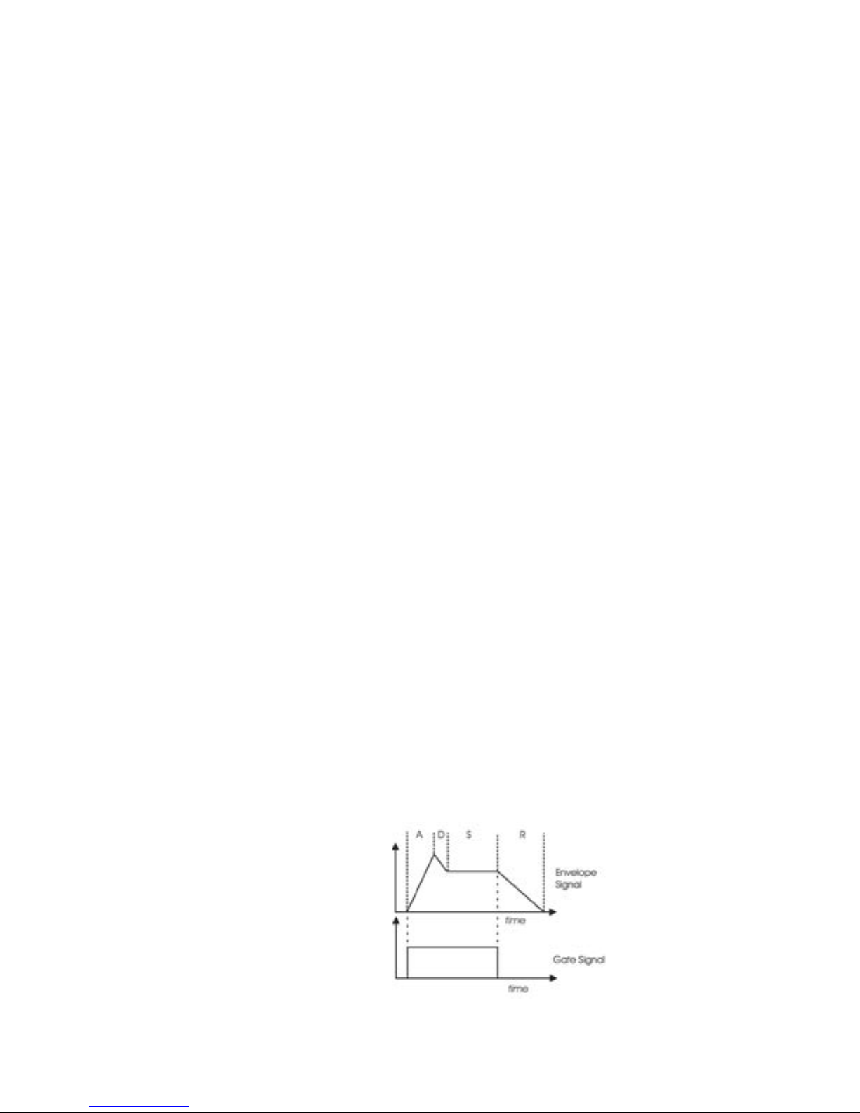
Envelope Gate:
The envelopes are triggered by a gate signal. The envelopes will sustain as long as a gate signal is
present. When the gate is off, the Release portion of the envelope is executed as shown below. The
switch labeled KEYB/ ON/EXT selects whether the envelopes are triggered from the keyboard, or
from a programmable gate source. When KEYB (Keyboard) triggering is selected, the envelopes are
triggered by a MIDI Note On. When the switch is set for ON/EXT (On/External), the envelope gate
sources are set by the programmable gate sources in EDIT mode, called ‘Fil. ENV Gate SRC’ (Filter
Envelope Gate Source) and ‘Vol. ENV Gate SRC’ (Volume Envelope Gate Source). The default for the
programmable gate sources is ‘Env Gate Input’ which defaults to ON. In this case the envelopes sustain
at the level determined by the respective envelope SUSTAIN controls. This is useful for keeping the
envelopes sustaining without holding a key down, when you want to process an external audio signal
through the lters with out using the keyboard, or to create drones. This also allows separate gate
sources for the two envelopes.
Envelopes sustain as long as a Gate
Trigger is present. The Release phase
starts when the Gate Trigger stops.
Page 28
Voyager User’s Manual - The Components
Related Controls:
Release Switch:
The release time of the envelopes is set by their respective RELEASE control knob, but this control can also
be switched OFF. On the Voyager keyboard , there’s a dedicated RELEASE switch located in the left-hand
control panel for this. On the RME, the RELEASE function is switched on or off in software (in the PANEL
mode menu). The RELEASE function can also be activated by sending a MIDI CC message 64 (0-63 = OFF,
64-127 = ON) to either the Voyager keyboard or RME.
The Release function is actually a divider for the release time, so if the RELEASE
control knob is set to 10, the release of the envelopes will not be absolutely abrupt
with the RELEASE ON/OFF function switched off.
Additional CV Control (applies to all Voyager keyboards and the RME with the VX-352 CV Input Expander only):
Gate (Envelope Gate Input):
The GATE jack allows you to connect a footswitch or input a CV gate signal to remotely trigger both
Envelope Generators. This input triggers the EG’s only when the front panel ENV GATE switch is set to
‘ON/EXT’. If the ENV GATE switch is set to ‘KEYB’, any input on the GATE jack will be ignored.
Release:
The RELEASE jack allows you to connect a footswitch or input a CV gate signal. Pressing the footswitch
or applying a gate signal (+5V) enables the Release phase of both Envelope Generators regardless of
the setting of the RELEASE switch.
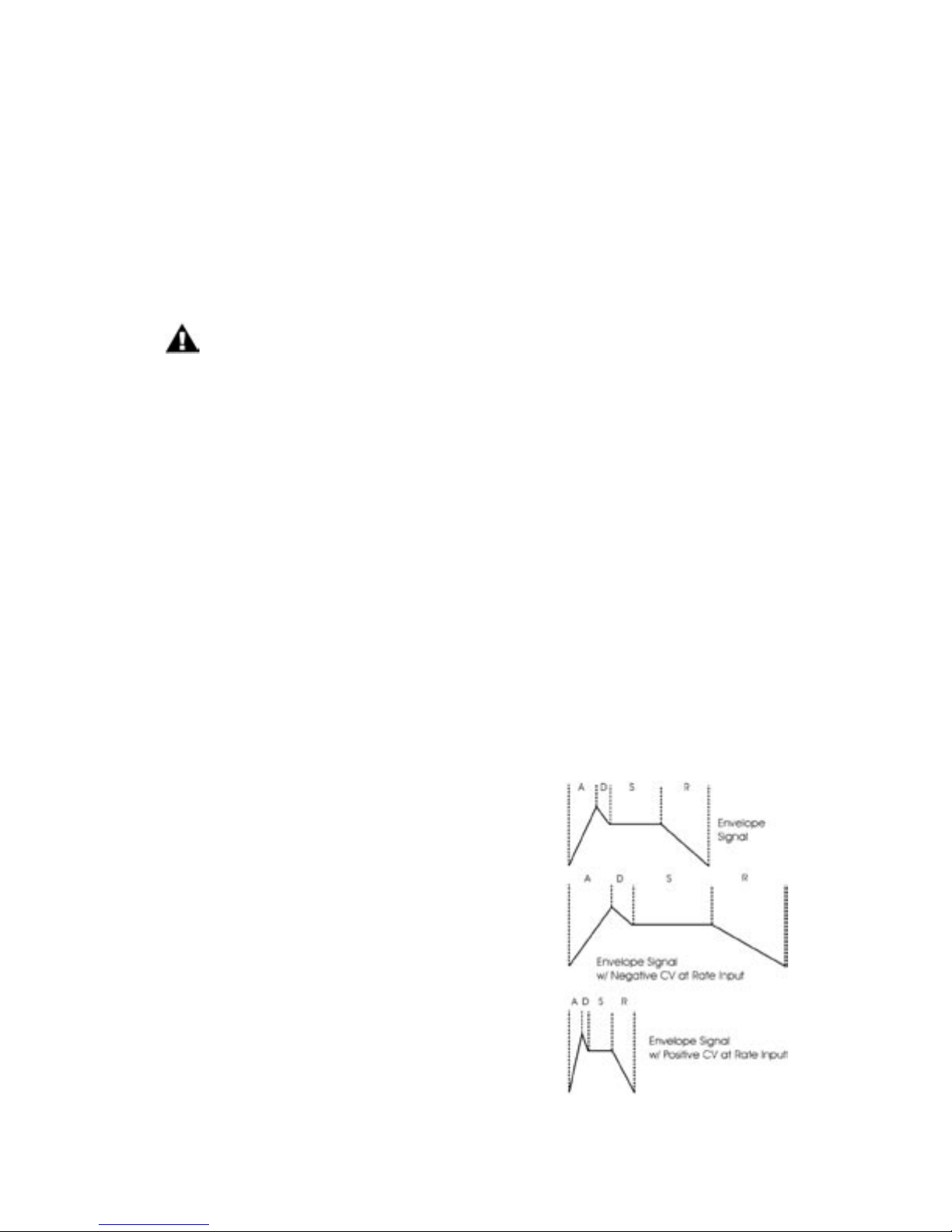
Rate (Rate Control Input):
The RATE jack is a CV input for external control of the Voyager’s envelope time constants, using either a
CV or expression pedal. The effective input range is-5V to +5V and effects both envelopes. A positive
voltage applied to the RATE jack will decrease the attack, decay
and release times from the envelope panel knob settings, and a
negative voltage will increase the attack, decay and release times
from the panel knob settings as shown.
The envelope AD&R parameters
will expand and contract based on
the voltage at the RATE jack.
Page 29
Page 31
Voyager User’s Manual - The Components
Voyager User’s Manual - The Components
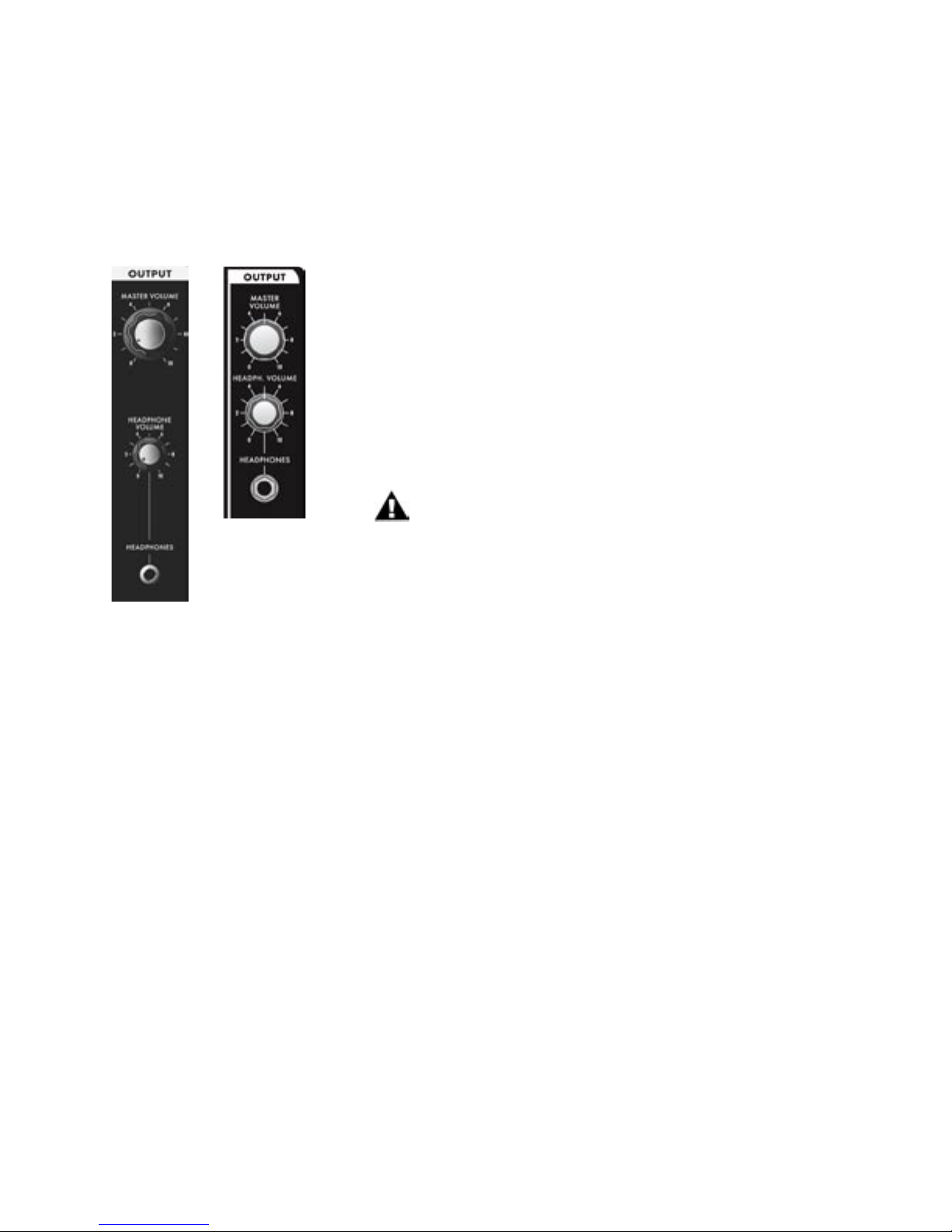
E. The Output Section
The Voyager has two audio outputs. There is a Voltage Controlled Amplier (VCA) for each output, which
allows for stereo functions such as panning or the dual lowpass ltering. The main control for the volume is
the Master Volume control. The Volume Envelope modulates the output VCAs.
Output Section controls:
Master Volume:
The MASTER VOLUME knob is the main volume control. Full-clockwise
is maximum output, full-counterclockwise silences the Voyager. .
Headphone Volume:
This HEADPHONE VOLUME knob controls the volume that appears
on the HEADPHONE OUTPUT jack. Full-clockwise is maximum
output, full-counterclockwise silences the Voyager.
In the RME, the Headphone Volume knob can be
reprogrammed to act as a Modulation Wheel controller.
Voyager
RME
Headphone Output:
The HEADPHONE OUTPUT connection is a ” TRS jack that outputs
the Voyager signal to a pair of stereo headphones.
Voyager
Keyboard
Additional CV Control (applies to all Voyager keyboards and the RME with the VX-352 CV Input Expander
only):
Volume:
The VOLUME jack allows you to connect an external CV or expression pedal to control the output
volume. Both VCA’s are effected by this connection. The effective input range is 0 to +5 V, where
0V = Volume OFF, and +5V = Full Volume.
Pan:
The PAN jack allows you to connect an external CV or expression pedal to control panning between
the right and left outouts. The effective input range is -5 to +5 V, where -5V = Fully Left and
+5V = Fully Right. If an expression pedal is plugged into the PAN jack, the pedal will reach its full
positive effect over just half of its useful travel, since it gets +5v from the PAN jack. Note also that you will
not be able to pan left with the pedal without additional offset programming because the expression pedal
voltage does not go below 0V.
Page 30
Voyager User’s Manual - The Components
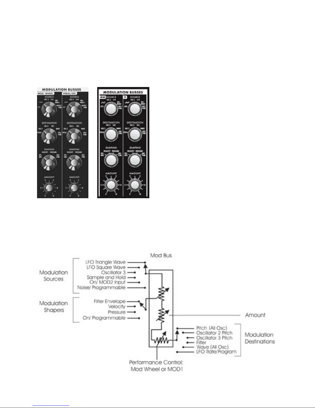
F – The Modulation Buss Section
Modulation is the heart of making interesting sounds with analog subtractive synthesis. The Voyager’s two
Modulation Busses open up a world of modulation possibilities that were not available on the original
Minimoog.
The Modulation Busses allow you to select a variety
of modulation sources, destinations, modulation
shaping, and amounts. The two Mod Busses are
labeled MOD WHEEL and PEDAL/ON (labeled as
‘MW’ and ‘P’ on the Voyager RME, respectively). The
performance control for the MOD WHEEL Buss is
the Modulation Wheel itself (on the RME, it’s MIDI
CC1, which is the default Mod Wheel CC message).
The performance control for the PEDAL/ON Buss is
the MOD 1 Input on the Voyager keyboard; for the
RME, it’s the MOD 1 input on the RME VX-352 CV
Expander (the MOD 1 parameter is also addressable
through a MIDI CC2 message or through the EDIT
Mode function called ‘Pot Mapping’).
The MOD 1 input can accept an expression pedal
like the EP-2, and is used like the Modulation Wheel
Voyager
Keyboard
Voyager
RME
to fade in and fade out the desired modulation.
With nothing plugged into the MOD 1 input, the
AMOUNT control of the PEDAL/ON buss sets the
modulation amount.
The diagram below shows the conguration of a single Mod Buss, but the controls for both busses are the
same.
Page 31

Page 33
Voyager User’s Manual - The Components
Voyager User’s Manual - The Components
Three controls modify the amount of modulation: the AMOUNT control, the SHAPING control, and the
Mod Wheel (for the Mod Wheel Mod Buss) or MOD1 level (for the Pedal/On Mod Buss). The AMOUNT
control sets how much both the Mod Wheel/MOD1 Input and the Shaping CV allow the mod source
through to the mod destination.
To try out a simple modulation effect, make the following settings on the MOD WHEEL Buss:
- Set the LFO RATE control to about 6 Hz
- Set the SOURCE control to the Triangle wave
- Set the SHAPING control to ON/PGM
- Set the DESTINATION control to PITCH
- Set the AMOUNT control to 5
These settings allow the Mod Wheel performance control to be used to fade in the modulation, which
should sound something like vibrato. This is a simple use of a Mod Buss. The exibility of the two Modulation Busses offer a wealth of modulation possibilities which make the Voyager an incredible sound design
tool.
Modulation Buss Section Controls:
Source:
The SOURCE control selects the source of the modulation. The modulation source is actually choosen
through a combination of the SOURCE control and software modulation options. The Source selections
are:
- (the LFO Triangle wave)
- (the LFO Square wave)
- OSC 3 (Oscillator 3)
- S+H (the LFO Sample and Hold output)
- ON/MOD2: If nothing is plugged into the MOD2 jack, this selection is ON, but it can also
be addressed either through the EDIT Mode function ‘Pot Mapping’, or MIDI CC 4.
- NOISE/PGM: This is a programmable source for the mod bus. Noise is the default.
The programmable modulation sources are set in the EDIT mode menu
functions ‘MOD WHEEL PGM SOURCE’ or ‘PEDAL PGM SOURCE’.
Shaping:
The SHAPING control selects the modulation shaping options. Shaping is a way to dynamically change the
amount of modulation . The Shaping selections are:
- FILT ENV: This allows the Filter Envelope to shape the amount of Modulation before the
Mod Wheel or MOD1.
- VELOCITY: This allows Keyboard Velocity to shape the amount of Modulation before the
Mod Wheel or MOD1.
- PRESSURE: This allows Keyboard Aftertouch (Pressure) to shape the amount of Modulation
before the Mod Wheel or MOD1.
- ON/PGM: This is a programmable shaping option for the mod bus; ON is the default. Both
Mod Busses share two programmable Shaping Sources that are summed together.
These sources are available in the EDIT mode as ‘PGM Shaping 1 SRC’ and
‘PGM Shaping 2 SRC’.
Page 32

Voyager User’s Manual - The Components
Destination:
The DESTINATION control selects the destination of the modulation. The modulation destination is cho-
sen in the same manner as the source. The modulation destination selections are:
- PITCH (the pitch of all three oscillators)
- OSC2 (the pitch of Oscillator 2 only)
- OSC3 (the pitch of Oscillator 3 only)
- FILTER (the Cutoff Frequency of the lter)
- WAVE (the waveforms of all 3 oscillators)
- LFO/PGM: This is a programmable destination for the Mod Bus; LFO Rate is the
default. Programmable Mod destinations are set in the EDIT mode using the
menu functions ‘PGM M-WHL DEST’ (Programmable Mod Wheel Destination)
and ‘PGM PEDAL DEST’ (Programmable Pedal Destination).
Amount:
The AMOUNT control is used to set the maximum amount of modulation that is sent to the modulation
destination. When the AMOUNT control is set to 0, no modulation will pass. When the AMOUNT is
set to 10, the maximum amount of modulation is sent to the destination when the performance controller
(Mod Wheel or MOD1 level) is all the way up.
Related Controls:
Mod Bus Performance Controllers:
The Mod Wheel and MOD 1 Input are performance controllers for the Mod Wheel Modulation Bus and
Pedal/ON bus respectively. These performance controllers are the nal stage in determining the amount
of modulation sent to the selected destination. When these controllers are set to maximum, the modulation amount is determined by the AMOUNT control. When these controllers are set to 0, the modulation
amount is 0.
1. Although the RME has no built-in performance controllers, the Mod Wheel from a
MIDI controller keyboard will produce the same result as described here, providing it
is sending MIDI CC1 messages.
2. For the RME, the MOD 1 Input is only available if the optional VX-352 CV Expander
is connected. Without the VX-352 connected, the Pedal Bus will default to ‘ON’.
Page 33

Page 35
Voyager User’s Manual - The Components
Voyager User’s Manual - The Components
Additional CV Control (applies to all Voyager keyboards and the RME with the VX-352 CV Input Expander
only):
MOD 1:
The MOD 1 jack accepts an expression pedal or control voltage from 0 to 5 Volts. This input is used as the
performance control for the PEDAL/ON Mod Bus. With nothing plugged into this jack, the voltage here is
5V (the ‘ON’ state). With an input applied, when the voltage is at 0, no modulation is sent to the PEDAL/ON
Modulation Destination. When the Voltage at the MOD1 is at 5 Volts, the Modulation is sent to the destination at the level set by the PEDAL/ON AMOUNT control.
MOD 2:
The MOD 2 jack allows you to apply an external modulation source into the MOD busses. The input
accepts an expression pedal or a control voltage of –5 to +5. With nothing plugged into this jack, the voltage
here is 5 V (the ‘ON’ state). When the SOURCE control is set to ‘ON/MOD2’, the voltage applied to this
jack becomes the Modulation Source.
Page 34

Voyager User’s Manual - The Components
G – The LFO/Sample and Hold Section
The Voyager has a dedicated Low Frequency Oscillator (LFO) and Sample and Hold (S+H) function. The
LFO produces triangle and square waves that oscillate from .2 to 50 Hz. Both the triangle and square wave
outputs can be selected as modulation sources in the Mod Busses.
For the Sample and Hold circuit, the LFO’s square wave is used
as the S+H Trigger input, while the Voyager’s Noise source is used
for the S+H Input signal. For each positive-going cycle of the LFO
square wave, the voltage at the input of the S+H circuit is sampled
and held until the next cycle. Since the sample source is Noise (a
random signal), the voltage that appears at the output of the S+H
circuit is a random voltage that changes in time with the LFO.
The Voyager’s CV Interface jacks (on the back panel of the Voyager
keyboard, or on the RME’s VX-352 CV Expander) allow additional
exibility with the Sample and Hold circuit. For example, if a plug
is inserted into the S+H Gate input, it will disconnect the LFO
trigger; an external gate signal can then be used to trigger the S+H
circuit. Similarly, a plug inserted into the S+H Input jack disconnects
Voyager
Keyboard
Voyager
RME
the Noise source from the S+H input. In this circumstance when
the S+H circuit is triggered, the voltage at the tip of the plug is
held at the output of the S+H circuit. This makes it possible to get
“staircase” modulation patterns. as shown below.
The Voyager’s Sample and Hold circuit can
create more than just random signals –
interesting stepped modulation patterns
are also possible.
Page 35

Page 37
Voyager User’s Manual - The Components
Voyager User’s Manual - The Components
LFO/Sample and Hold Section Controls
LFO Rate:
The LFO RATE control sets the rate of the dedicated LFO. The control range is 0.2 to 50 Hz.
LFO Sync:
The LFO SYNC control selects the trigger method for starting the LFO waveform. There are four trigger
modes:
- OFF/SYNC: This setting allows the LFO to be free running unless there is a
connection to the LFO SYNC input (see below).
- MIDI: This setting allows the division of the MIDI clock signal (set up in the EDIT
mode function ‘MIDI CLK Divider’) to retrigger the LFO. Note that the LFO is
an analog circuit, and does not automatically sync to MIDI clock; it is restarted
much in the manner of oscillator sync, and does not defeat the Rate control.
- KB (Keyboard): This setting allows the LFO to be retriggered when a MIDI ‘Note On’
message is received.
- ENV. GATE: This setting allows an input to the Envelope Gate Source jack (part of
the Envelope CV inputs) to restart the LFO.
Additional CV Control (applies to all Voyager keyboards and the RME with the VX-352 CV Input Expander only):
LFO Rate:
The LFO RATE jack accepts an expression pedal or a control voltage from -5 to +5V. A positive voltage
here adds to the position of the LFO RATE control, while a negative voltage will subtract from the position
of the LFO RATE control.
By applying an external voltage to the LFO RATE jack you can control the LFO
frequency well beyond the specied range. Rates lower than one cycle per minute
are possible, as are frequencies that go well into the audio range.
LFO Sync:
The LFO SYNC jack accepts a footswitch or a +5V Gate input. Closing the footswitch or applying a gate
here will retrigger the LFO waveform.
S&H In (Sample and Hold Input):
The S&H IN jack accepts an expression pedal or a control voltage from -5 to +5V. The voltage on this jack
is the signal source for the Sample and Hold circuit input.
S&H Gate (Sample and Hold Gate):
The S&H GATE jack accepts a +5V Gate input. Applying a gate signal here will trigger the Sample and Hold
circuit.
The S&H GATE jack will only work with a +5V Gate input, not a footswitch.
Page 36

Voyager User’s Manual - The Components
H – Keyboard and Left-Hand Controllers
The Voyager has a 44-note keyboard (3 octaves, F to C),
just like the original Minimoog. Unlike the original, however,
the Voyager has an octave transpose feature (accessed by double-pressing the EDIT button) giving it a playable range of 7
octaves. Also, the Voyager’s keyboard transmits MIDI Note On
and Note Off messages polyphonically, and produces velocity
control and aftertouch (pressure) voltages monophonically.
To the left of the keyboard is the Left Hand Controller Panel,
which contains the Pitch Bend and Mod Wheel performance
controls, and the Glide and Release switches.
Pitch Bend Wheel:
This spring-loaded control affects the pitch of all oscillators. The amount of pitch bend can be set for each
direction (UP/DOWN) independently for each preset.
Modulation Wheel:
This control sets the amount of modulation that is sent to the modulation destination of the Mod Wheel
Bus. Each preset has the Modulation Wheel programmed to introduce some additional dimension to the
sound. As you explore the presets, don’t forget to try the Modulation Wheel to hear this added effect on
the sound.
Glide:
The GLIDE switch turns the Glide function ON and OFF. The glide rate is controlled by the GLIDE RATE
panel control
Release:
The RELEASE switch is used to shorten the release time of both the Filter and Volume envelopes. You will
notice that with very long release times, the release time will be shortened when the RELEASE switch is
engaged, but not off all the way.
The expressive use of the Pitch Bend and Modulation Wheels is the key to breathing musical life
into your performances. For example, a small amount of pitch bend (a few semi-tones) will allow
you to perform guitar-like bends, while a large amount can be useful for extreme ‘dive bomb’ pitch
effects. The Mod Wheel can be programmed to introduce standard modulation effects like vibrato,
tremolo or lter sweeps, or it can control something less expected, like EG-swept oscillator sync.
Although the actual performance technique with these controls is beyond the scope of this manual,
we recommend listening to recordings of synthesizer players, guitarists and other soloists to learn
the various ways these controls can be used effectively.
Page 37

Page 39
Voyager User’s Manual - The Components
Voyager User’s Manual - The Components
I – Touch Surface Controller (Voyager keyboard models only)
The Touch Surface Controller is a real-time, three-dimensional
control surface. It can be used to impart complex gestures
to the sound of the Voyager by touching it, by moving a
nger around on it or by tapping it. A nger movement from
left to right controls the X-axis, an up and down movement
controls the Y-axis, and the amount of the Touch Surface that
is covered by the nger controls the Area. Additionally, when
the Surface is touched a Gate signal is generated, providing a
total of four individual control signals (X, Y, A and Gate) that
can be routed to a number of the Voyager’s parameters.
The control signals generated by the Touch Surface Controller can be routed two ways:
- Destinations can be programmed using the ‘Touch Surface Destinations’ selection in the
EDIT mode menus. There are 32 possible destinations that can be selected for each
axis (X, Y A) and 14 possible destinations for the Gate. These congurations are saved
individually per Preset.
- The Touch Surface X and Y axes can be selected as Programmable Mod Buss Sources
using the EDIT mode menus ‘PGM Mod Whl Source’ and ‘PGM Pedal Source’
Details on programming Touch Surface Controller destinations are covered in the EDIT Mode section.
There is no right or wrong way to use the Touch Surface Controller; experimentation is the key.
It is an exciting way to explore synthesis performance – with 3 control signals generated from
a single nger in contact with the Touch Surface, it is like turning three knobs at the same time
– giving you the capability to “morph” sounds in a variety of ways.
Page 38

Voyager User’s Manual - The Components
J – The Back Panel
The back panel provides for all of the Voyager’s connectivity, including power, MIDI, audio and CV expansion
connetions.
POWER CONNECTOR:
This is a standard AC power inlet, Use only a power cord designed to mate with this receptacle. The
Voyager power supply is designed to work with power inputs of 100-240 VAC; 50-60 Hz.
IMPORTANT SAFETY NOTE – Do not alter the power connector in any way. Doing so can
result in the risk of shock, injury or death. Be familiar with the safety instructions printed at the
beginning of this manual. If the connector is damaged, refer servicing to qualied personnel
only.
LEFT/MONO and RIGHT OUTPUTS:
The LEFT/MONO and RIGHT outputs on all Voyager Keyboard models are unbalanced ” TS jacks for use
with standard TS instrument cables. On the Voyager RME, the LEFT/MONO and RIGHT outputs are TRStype jacks that can be used for either balanced or unbalanced connections. An OUTPUT MODE switch
on the RME back panel allows you to select between balanced and unbalanced operation (see the Output
Mode switch descriptionbelow). When connecting to a balanced input, use ” TRS to ” TRS cables for
” inputs, or ” TRS to male XLR cables for XLR inputs.
When just the LEFT/MONO output is connected, both channels are summed to this output. A stereo
signal is created when both the LEFT/MONO and RIGHT outputs are used. When the Voyager Filter is set
to ‘Dual Lowpass Mode’, the RIGHT output can be used by itself for acheiving a single lowpass lter sound.
OUTPUT MODE SWITCH (RME only):
The RME’s outputs can be operated as either balanced or unbalanced outputs. In balanced output
mode, the output Jacks provide an electronically (non-transformer) balanced signal with a nominal output
impedance of 600 Ω. In unbalanced mode, the outputs are “oating” TRS connections. Set the OUTPUT
MODE switch to its proper position prior to power up, and do not change its position while the RME is
amplied.
EXTERNAL AUDIO IN:
This is an unbalanced ” TS input that accepts any instrument or line level signal and routes the signal to
the Mixer. A dedicated EXTERNAL input control on the Mixer adjusts the signal level.
MIXER OUT/FILTER IN:
This is a ” TRS jack that is used for inserting a processing device between the Voyager’s Mixer and Filters.
The tip is the send and the ring is the return (see the illustration on page 19).
BNC Lamp Connector (Voyager keyboard models only):
This is a 12VDC BNC outlet for a gooseneck lamp.
Page 39

Page 41
Voyager User’s Manual - The Components
Voyager User’s Manual - The Components
CV/EXPRESSION INPUTS (applies to Voyager keyboard models only):
The CV/Expression Inputs are ” TS jacks color coded with a red nut. These jacks accept an input from
an expression pedal such as the Moog EP-2, or a CV from -5V to +5V. Note that some inputs, such as the
MOD 1and VOLUME operate only from 0V to +5V, so applying a negative CV to these inputs will have no
effect.
GATE/FOOTSWITCH INPUTS (applies to Voyager keyboard models only):
The Gate/Footswitch Inputs are ” TS jacks color coded with a blue nut. These jacks accept an input from
a footswitch (a momentary, normally-closed footswitch like the Moog FS-1) or a +5 Volt Gate Signal.
The Sample and Hold input jack accepts a Gate input only, not a footswitch.
MIDI CONNECTORS:
These are connectors for MIDI IN, OUT and THRU.
ACCESSORY PORTS:
All Voyagers (keyboard and RME versions) have a DB-25 connector which connects the Voyager to the
optional VX-351 Voyager CV Expander. This device outputs all the CV and Gate signals generated by the
Voyager on ” jacks. The Voyager RME adds a second DB-25 connector which connects to the optional
VX-352 CV Expander. This device provides the same ” CV and GATE inputs that appear on the back
panel of Voyager keyboards, and allows the RME to be interfaced with other CV equipment. For more on
the VX-351 and VX-352, see Appendix G
1. You can use the Voyager to process any audio signal simply by plugging into the
EXTERNAL AUDIO IN jack. To hear the external audio signal without having to hold
down a key on the keyboard, set the ENV. GATE switch to ‘ON/EXT’. This will trigger the
envelopes. Make sure that the Volume Envelope SUSTAIN control is set to maximum.
The Volume Envelope will remain at its Sustain level until the ENV. GATE switch is
changed to ‘KEYB’.
2. The Voyager’s EXTERNAL AUDIO INPUT is not limited to processing monophonic
signals - it can work well for processing polyphonic signals, too. For example, connect
the MIDI Out of the Voyager to the MIDI Input of another polyphonic keyboard, then feed
that audio output back into the Voyager through the EXTERNAL AUDIO IN. Now you
have a polyphonic source that is being affected by the Voyager’s Filter and EGR circuits.
3. For the ultimate in genuine Moog polyphony, try connecting several Voyagers together,
or a combination of Voyagers and Little Phatty synthesizers. For more information on
polyphony connection options, see the MIDI KEY ORDER function on page 65.
Page 40

Voyager User’s Manual - The Components
K – Interface Panel
The Interface Panel, located in the top center of the instrument, provides a status display and controls for
all of the Voyager’s software functions and instrument settings.
Voyager Keyboard Voyager RME
The status display is an LCD screen located within the Interface Panel. When the Voyager is rst powered
on, the screen will display a greeting message. The message will stay on the screen for a few seconds, and
then the screen will display the active preset. This preset will be the last preset in use when the Voyager was
powered down.
The Voyager has three operating modes which are accessed on the Interface Panel:
PANEL: Used for accessing the Voyager’s presets and performance functions.
EDIT: Used for editing the parameters of a preset which are not accessed through the front panel
control knobs and switches. Naming and saving presets is done in EDIT mode.
MASTER: Used for accessing global settings for the Voyager, and data send and receive functions.
The LED’s located above the PANEL, EDIT and MASTER buttons will be lit when the respective operating
mode is selected. A MIDI LED located near the LCD screen will light whenever the Voyager receives an
incoming MIDI message on the correct MIDI channel.
Section Controls:
Panel:
Pressing the PANEL button places you in Panel Mode, where you select Voyager presets and basic perfor-
mance functions. For complete description of Panel Mode operations and functions, see page 43.
Edit:
Pressing the EDIT button places you in Edit Mode, where you can edit menu-based preset parameters. For
a complete description of the Edit Mode operations and functions, see page 48.
Master:
Pressing the MASTER button places you in Master Mode, where you can access global settings, MIDI options
and operating system functions. For a complete description of the Master Mode operations and functions,
see page 61.
Page 41

Voyager User’s Manual - The Components
Enter:
The ENTER button is used to enter and store all changes (presets and global), and is occasionally used as a
navigation control in certain menus.
Cursor :
The CURSOR button is used to navigate the display and make menu selections.
-1/+1:
The -1/+1 buttons are used to select presets in Panel Mode, and choose functions and select parameter
values in Panel, Edit and Master modes.
Page 42

Voyager User’s Manual - PANEL Mode
Panel Mode
Panel Mode is used to access presets and other performance functions. Pressing the PANEL button
accesses Panel Mode. The LED above the PANEL button will be lit, and the preset name and location will
be displayed. A preset consists of all the stored settings of the front panel controls (except FINE TUNE)
plus the preset’s software parameters. Once a preset is called up, the front panel controls and software
parameters can be used to adjust the parameters of the sound. When a front panel control is changed,
the stored value jumps to the absolute position of the control. Changes to a preset can be saved in Edit
Mode (see ‘SAVE PRESETS’, page 62). If you wish to get back to the original sound after modifying the
parameters, simply press ENTER and the original preset will be reloaded. Pressing ENTER stores the
tweaked sound into a memory buffer that can be brought back through the RECALL function in Edit Mode.
Once the program number is changed, the buffer is cleared.
Presets are stored in the Voyager’s 896 memory locations. These memory locations are organized into 7
banks of 128 presets each, and all locations can be overwritten. The 7 banks are labeled A to G, and bank
locations are numbered from 1 to 128. Presets can be changed incrementally using the -1/+1 buttons. You
can also scroll through presets in a bank using the EXTERNAL level control on the Mixer (when the Mixer’s
EXTERNAL switch is in the OFF position), or specify a preset through a MIDI Program Change command.
To change banks, press and hold the CURSOR button and use the -1/+1 buttons to step through the banks.
Banks can also be selected through a MIDI Bank Select message.
Once in Panel Mode, pressing the PANEL button a second time accesses the Panel Mode menus shown
below. Voyager keyboard editions have eight Panel Mode functions that span two pages, while the RME has
a different set of twelve Panel Mode functions that span three pages as shown.
Voyager Keyboard
Page 43
Voyager RME

Page 45
Voyager User’s Manual - PANEL Mode
Voyager User’s Manual - PANEL Mode
To select a Panel Mode menu function, use the -1/+1 buttons to highlight the desired function and then
press ENTER. A description of the Panel Mode functions follows.
In PANEL, EDIT or MASTER mode, when you reach the bottom of the menu pages, the next “-1”
button press will wrap back to the top item on the rst menu page.
QUICK MODE:
QUICK MODE is used to determine whether the presets change by simply pressing the -1/+1 buttons, or by a combination of +1/-1 and ENTER.
When enabled, Quick Mode (-1/+1 changes presets immediately) is ideal
for auditioning Presets. Disabling Quick Mode is designed for performing live, where you may want to call up a new preset while continuing to
play the current preset. With Quick Mode disabled, the new preset only
becomes active when you press the ENTER button. To change the Quick
Mode, use the CURSOR to highlight the desired choice and press ENTER.
PARAMETER DISPLAY:
PARAMETER DISPLAY is used to monitor changes to the values of a
preset’s parameters. There are three choices for this feature as shown.
Choose ‘YES’, and a change in the position of a knob or switch on the
front panel causes the display to show the preset’s stored value and the
new value simultaneously. The last parameter changed will be displayed.
Choose ‘3 sec.’, and the current and stored values are displayed for approximately 3 seconds before the display returns to the preset name and
number. Choose ‘NO’ and this function is off. To make a change in the
Parameter Display menu, use the CURSOR to highlight the desired choice
and press ENTER.
In previous versions of the Voyager operating system, stepping could occur when more than one potentiometer (pot) was adjusted at the same time, resulting in a lack of smooth changes for one or more parameters. The current Voyager O.S. has been improved to eliminate stepping when multiple pots are tweaked,
but it requires that the PARAMETER DISPLAY function be set to ‘NO’ to ensure smooth operation.
MASTER VOLUME (Keyboard Editions only):
MASTER VOLUME is used to determine whether the stored Master Volume value is loaded when a new preset becomes active. If this is off, then
this value is determined by the current position of the MASTER VOLUME
control. To make a change in the Master Volume menu, use the CURSOR
to highlight the desired choice and press ENTER.
Page 44

Voyager User’s Manual - PANEL Mode
HEADPHONE VOLUME (Keyboard Editions only):
HEADPHONE VOLUME is used to determine whether the stored Headphone Volume value is loaded when a new preset becomes active. If this
is off, then this value is determined by the current position of the HEAD-
PHONE VOLUME control. To make a change in the Headphone Volume
menu, use the CURSOR to highlight the desired choice and press ENTER.
MASTER/HP VOLUME (RME only):
MASTER/HP VOLUME is used to determine whether the stored Master
Volume and Headphone Volume values are loaded when a new preset is
selected. If this is off, then these values are determined by the current position of these controls. To make a change in the Master/HP Volume menu,
use the CURSOR to highlight the desired choice and press ENTER.
T.S. REDUCTION:
For the RME, the Touch Surface Inputs are on the optional VX-352 CV Expander. With
the VX-352 connected, you can route any 0 to +5V control input connected to the Touch
Surface inputs to any Touch Surface Destination through the RME’s software and save in
a preset.
REAL PANEL PARAM.:
GLIDE FUNCTION (RME only):
T.S. REDUCTION (Touch Surface Reduction) thins the number of MIDI
CCs sent by the Touch Surface Inputs when more than one is used at a
time. The amount of MIDI data produced by the Touch Surface can be
immense, and can crash some MIDI devices. To make a change in the T.S.
Reduction menu, use the CURSOR to highlight the desired choice and
press ENTER.
REAL PANEL PARAM (Real Panel Parameters) is a function that enables
the operation of the Voyager from the actual settings of front panel
controls, rather than preset memory. If you select ‘YES’ the sound
produced when the Voyager is played will be determined by the settings
of the front panel controls. To make a change in this menu, use the
CURSOR to highlight the desired choice and press ENTER.
Page 45
This function works like the GLIDE switch on the left-hand control panel
of the Voyager keyboard – it switches the Glide function ON or OFF. To
make a change in this menu, use the CURSOR to highlight the desired
choice and press ENTER. The change will take effect for the current
preset Like all changes, if you wish to keep the change you must save the
preset. For more information, see ‘SAVE PRESET’ in the Edit Mode section.

Page 47
Voyager User’s Manual - PANEL Mode
Voyager User’s Manual - PANEL Mode
RELEASE FUNCTION (RME only):
This function works like the RELEASE switch on the left-hand control
panel of the Voyager keyboard – it switches the Release function ON
or OFF. To make a change in this menu, use the CURSOR to highlight
the desired choice and press ENTER. The change will take effect for the
current preset Like all changes, if you wish to keep the change you must
save the preset. For more information, see ‘SAVE PRESET’ in the EDIT
Mode section.
The RME’s GLIDE and RELEASE functions can also be enabled automatically by adjusting
the GLIDE RATE and VOLUME RELEASE controls. If either function is switched OFF in a given
Preset, adjusting the GLIDE RATE or VOLUME RELEASE controls to a non-zero value will enable
that function. If the function is already ON, it will switch OFF when the control is set to ‘0’.
If the RME is congured to display the parameter values, the LCD will display the ON/OFF status
and the actual parameter value of the selected function:
HELP/CATEGORY:
The HELP/CATEGORY function allows you to display either a Help
message or the Sound Category of a preset on the bottom line of the
Panel Mode display. Help messages provide operational assistance and
users control options, such as the “Cursor selects Y/N” message shown
at left. The Help message text changes appropriately depending on the
information displayed on the LCD.
Sound Categories are designed to assist in organizing presets for quick identication when auditioning
sounds. This can be especially useful in conjunction with the Voyager Editor software. Sound Category is
a parameter that can be assigned in Edit Mode and saved as a part of a preset. When ‘Category’ (sound
category) is chosen instead of ‘Help Line’, the bottom of the LCD will display the sound category of the
selected preset as shown below. To make a change to the Help/Category function, use the CURSOR
to highlight the desired choice and press ENTER.
“Bright Bass” is one of 32 assignable
sound categories. For a complete list
of all the categories as well as details on
assigning sounds, refer to Edit Mode
section 6.2 - SOUND CATEGORY
Page 46

Voyager User’s Manual - PANEL Mode
LCD CONTRAST
The LCD CONTRAST function changes the viewable angle of the LCD
display. To change this setting, use the -1/+1 buttons to adjust the contrast
level. The change will immediately take effect (you’ll see the display
contrast change) and the new contrast value will be stored automatically.
LOCAL CONTROLS (RME only):
The LOCAL CONTROL menu provides Local ON/OFF control of three
groups of RME functions: Panel Knobs (Potentiometers), Panel Switches
(Switches), and Touch Surface. A fourth selection (All Controllers), allows
you to switch the Local Control of all three functions at once. To change
the status of any Local Control function, use the CURSOR to make
a selection and press the +1/-1 buttons to select ON/OFF. When all
changes have been made, press ENTER to enter the changes. To escape at
any time without changes, press PANEL.
When Local Control of any function is switched OFF, the RME will
display a ‘Local Control’ message upon power-up, showing the status of all
controls. To dismiss the message, press any button.
When Local Control of a given function is OFF, and the RME is set to
display parameter values, the LED will display a ‘LOCAL OFF’ message
when you adjust any related control. For example, if Local Control of the
Switches is OFF when you change a Switch position, the RME’s LED will
include a ‘LOCAL OFF’ message on the bottom line of the display. The
status of the switch position change will still be displayed, but the switch
will have no effect.
1. The RME’s front panel controls send MIDI data whether Local
Control is ON or OFF.
2. For Voyager keyboard editions, the LOCAL CONTROL function
is located in the Master Mode menu, function 1.2.
Page 47

Voyager User’s Manual - PANEL Mode
PANIC BUTTON (RME only):
The PANIC BUTTON function allows you to program the MASTER
button as a ‘panic’ button. When the PANIC BUTTON function is enabled,
pressing the MASTER button issues an ‘ALL NOTES OFF’ MIDI message
that silences the RME and resets the Pitch Bend and Mod Wheel controller
values. The message is also sent to the RME’s MIDI Out jack.
To enable the PANIC BUTTON function, select ‘YES’ and press ENTER.
To escape without changes, select ‘NO’ and press ENTER.
HP -> MOD-WHEEL (RME only):
The HP-> MOD-WHEEL function allows you to program the HEADPH.
VOLUME (Headphone Volume) knob to act as a Modulation Wheel
controller. When enabled, this function gives you front panel control of the
RME’s Modulation Wheel (MW) Buss Output.
To enable the HP-> MOD-WHEEL function, select ‘YES’ and press
ENTER. To escape without changes, select ‘NO’ and press ENTER.
When the HP -> MOD-WHEEL function is enabled, the Headphone
Volume knob no longer adjusts headphone volume.
OTHER PANEL MODE FUNCTIONS
RECEIVE SINGLE PRESET:
This does not appear as an option in the Panel Mode menu, but is used in conjunction with ‘Receive
Presets’ in Master Mode. In Master Mode, make sure SysEx is enabled in ‘Receive Presets’. Once this is
done, a single preset can be received to the current active preset location in Panel Mode. Once a preset is
received in the current active location, it can be auditioned. If you want that preset to become part of the
Voyager’s preset bank, you must save the imported preset. If it is not saved and the current preset number
is changed, the imported preset is wiped from the Voyager’s preset memory buffer.
COMPARE:
Compare is a feature in Panel Mode, linked to the Edit Mode ‘COMPARE TO PRESET’ function. Pressing the
CURSOR activates this function – loading the sound in the Compare buffer, and pressing ENTER returns to
the active preset. To load a Preset into the Panel Compare buffer, go to Edit Mode, select ‘COMPARE TO
PRESET’ and press ENTER. Use the cursor to move to the Preset eld. Press PANEL to go back to Panel
mode. Now when you press CURSOR, the preset should show as being loaded into the Compare buffer.
It will remain there until the Compare function is used in Edit Mode.
Page 48

Voyager User’s Manual - EDIT Mode
Edit Mode
Edit Mode is used to assign the parameters of a preset that are not accessible through the front panel
controls. Edit Mode is also used assign the preset sound category, set the MIDI clock divider, and name and
save presets. Press the EDIT button to enter Edit Mode. To select an Edit Mode function, use the
-1/+1 buttons to hightlight the desired function and then press ENTER.
All Voyager editions (keyboard and rack mount) have the same twenty four Edit Mode functions that span
six pages as shown below.
Voyager/RME EDIT menus
In addition to the functions shown above, Edit Mode also features an octave transpose function that allows
you to shift the Voyager’s Keyboard up to plus or minus two octaves. To access the transpose menu at any
time, press the EDIT button twice (press once if already in Edit
Mode). The display will appear as shown at left. Use the -1/+1
buttons to transpose the octave as desired (NULL is the Voyager’s
default setting). The new transpose setting will remain until it is
changed, or until the Voyager is powered off.
To exit the transpose menu, press EDIT.
The Envelope Gate switch must be set to ‘KEYB’ (keyboard) for the
octave transposition feature to be utilized.
Page 49

Page 51
Voyager User’s Manual - EDIT Mode
Voyager User’s Manual - EDIT Mode
Here are the Edit Mode functions:
1.1 COMPARE TO PRESET
The COMPARE TO PRESET function is used to compare the current Panel
sound to any other preset in the current Preset bank. Applications for this
include comparing an edited version of a sound to its original version in
memory, or to nd a preset location that you do not use where you can
store your current Panel Sound. The sound that is currently heard when
the Voyager is played is the one highlighted on the ‘Compare’ screen. The
CURSOR button is used to change between the panel sound and a preset.
The Preset number can be changed with the - 1/+1 buttons, but only
presets in the current bank can be selected.
If you leave the ‘Compare’ screen by pressing the PANEL button
and do not change the preset, you can still toggle between the panel
sound and preset sound by pressing ENTER for the panel sound and
CURSOR for the preset sound.
1.2 RECALL LAST SOUND:
The RECALL LAST SOUND function can be used to return to a previously
edited version of a sound. This is used in conjunction with Panel Mode.
If you are in Panel Mode and make changes to a preset and then press
ENTER, the sound reverts to the original saved settings. If you want to
get back to your edited sound, press the EDIT button and select the
‘RECALL LAST SOUND’ function. Use the CURSOR to select ‘YES’ and
press ENTER. You will now hear the changes you made to the preset. If
you wish to keep those changes, you must save the preset. See Edit Mode
function 6.4 ‘SAVE PRESET’ for more information.
The ‘Recall’ function can also be used to return to a preset sound after
the parameters are initialized or REAL PANEL PARAMETERS has been
switched on.
1.3 INIT. PARAMETERS (Initialize Parameters)
The INIT PARAMETERS function allows you to reset the current values of
the Voyager’s parameters to a single oscillator basic sound which can then
be used as a starting point for new sound development. To set the Voyager
parameters to an initialized state, use the CURSOR to select ‘YES’ and
press ENTER. A list of the complete initialization parameters appears in
Appendix B.
Page 50

Voyager User’s Manual - EDIT Mode
1.4 PITCH BEND AMT. (PITCH BEND AMOUNT):
The PITCH BEND AMT function allows you to set separate up and down
pitch bend ranges for each preset. To adjust the ranges, use the CURSOR
to toggle between the Pitch Bend UP and Pitch Bend DOWN parameters,
and use the -1/+1 buttons to select the desired range.
The selection ranges for the UP and DOWN parameters are:
Off +/- Fourth (default) +/- 2 Octaves
+/- 2 Semitones +/- Fifth +/- 2 Octaves & 5
+/- Minor Third +/- 1 Octave Pre. –Value
+/- Major Third +/- 1 Octave & 5
‘Pre. –Value’ is a user dened amount. The value of this is set with
the EXTERNAL level control on the Mixer. To set the value, simply
push the Pitch Bend Wheel forward and listen to the pitch change as
you rotate the EXTERNAL control, stopping when the desired interval
is reached.
2.1 PGM M-WHL SOURCE (Programmable Modulation Wheel Source)
PGM M-WHL SOURCE that allows you to program one of 8 additional
modulation sources to be used when the Mod Wheel Bus SOURCE
control is set to ‘NOISE/PGM’. To select a source, use the -1/+1 buttons
to highlight the desired selection and press ENTER.
The available sources are:
Noise (default) Oscillator 1
Filter ENV Oscillator 2
Amplitude ENV Touch Surface X
Smoothed Sample and Hold Touch Surface Y
th
th
2.2 PGM M-WHL DEST. (Programmable Modulation Wheel Destination):
Page 51
PGM M-WHL DEST allows you to program one of 8 additional
modulation destinations to be used when the Mod Wheel Mod Bus
DESTINATION control for the set to ‘LFO RATE/PGM’. To select a
destination, use the -1/+1 buttons to highlight the desired selection and
press ENTER.
The available destinations are:
LFO Rate (default) Osc. 1 Level
Filter Resonance Osc. 2 Level
Filter Spacing Osc. 3 Level
Panorama Noise Level

Page 53
Voyager User’s Manual - EDIT Mode
Voyager User’s Manual - EDIT Mode
2.3 PGM PEDAL SOURCE (Programmable Pedal Source)
PGM PEDAL SOURCE allows you to program one of 8 additional
modulation sources to be used when the Pedal/ON Bus SOURCE control
is set to ‘NOISE/PGM’. To select a source, use the -1/+1 buttons to
highlight the desired selection and press ENTER.
The available sources are:
Noise (default) Oscillator 1
Filter ENV Oscillator 2
Amplitude ENV Touch Surface X
Smoothed Sample and Hold Touch Surface Y
2.4 PGM PEDAL DEST. (Programmable Pedal Destination):
PGM PEDAL DEST allows you to program one of 8 additional modulation
destinations to be used when the Pedal/ON Bus DESTINATION control
is set to ‘LFO RATE/PGM’. To select a destination, use the -1/+1 buttons
to highlight the desired selection and press ENTER.
The available destinations are:
LFO Rate (default) Osc. 1 Level
Filter Resonance Osc. 2 Level
Filter Spacing Osc. 3 Level
Panorama Noise Level
3.1 PGM SHAPING 1 SRC (Programmable Shaping 1 Source)
3.2 PGM SHAPING 2 SRC (Programmable Shaping 2 Source):
There are two programmable shaping sources. Both shaping sources are
identical, and both are combined by the software and shared by the two
Mod Busses. When either of the Mod Bus SHAPING controls are in the
‘ON/PGM’ position, the programmable shaping values stored in memory
are applied to shape the Mod Buss source signal. Shaping is like an
additional level control for the modulation amount. As an example, if
Velocity is used as a shaping source, the higher the velocity value, the
more the Mod Source is passed to the Destination. PROGRAMMABLE
SHAPING SOURCE 1/2 also allows an offset value to be applied, which is
added to the shaper itself.
Page 52

Voyager User’s Manual - EDIT Mode
Programmable Shaping Sources are useful for creating presets that respond in complex ways. For instance,
you could assign both Keyboard CV (pitch) and Velocity Release (velocity) as the Programmable Shaping
Sources. With this assignment, the higher and the harder you play, more modulation source is passed to
modulate the destination. Many of the shaping sources are front panel rotary controls. A suggested
application using a front panel control as a shaping source is having the Filter Cutoff control the Modulation
amount. Programmable Shaping Sources can make for some highly interesting and interactive presets.
There are 43 assignable shaping sources for Programmable Shapers 1 and 2:
- Fixed Value (see below)
- Pitch Bend Wheel
- Modulation Wheel
- Velocity Release
- Pressure (AT)
- Keyboard CV
- Touch Surface X
- Touch Surface Y
- Touch Surface A
- Mod1
- Mod2
- LFO Rate
- Glide Rate
- Mod. Wheel Amt
- Pedal Amount
- Osc.1 Octave
- Osc. 1 Waveform
- Osc. 2 Frequency
- Osc. 2 Octave
- Osc. 2 Waveform
- Osc. 3 Frequency
- Osc. 3 Octave
- Osc. 3 Waveform
- Ext. Audio Level
- Osc. 1 Level
- Osc. 2 Level
- Osc. 3 Level
- Noise Level
- Filter Cutoff
- Filter Spacing
- Filter Resonance
- Filter KB Control Amt
- Filter Attack
- Filter Decay
- Filter Sustain
- Filter Release
- Filter Envelope Amt
- Volume Attack
- Volume Decay
- Volume Sustain
- Volume Release
- Master Volume
- Headphone Volume
The Fixed Value parameter is an offset voltage that can be used by itself or added to one of the shaping
sources. Fixed Value has a course adjustment labeled ‘HIGH’ and a ne adjustment labeled ‘LOW’. Both
HIGH and LOW Fixed Values are adjustable from -64 to +64 (a total range of +/- 2.5 V).
To congure the shaping parameters, use the CURSOR button to move between the SHAPING SOURCE,
the HIGH Fixed Value and the LOW Fixed Value elds, then use the -1/+1 buttons to make the selections.
3.3 KEYBOARD MODES
KEYBOARD MODE allows you to select one of 4 types of keyboard
priority for a preset. The keyboard priority determines what happens
when more than one key is pressed on the keyboard. To set the Keyboard
Mode, use the +/-1 buttons to select one of the following options:
Lower Key (the lowest key pressed sounds)
Higher Key (the highest key pressed sounds)
Last Key (the most recent key pressed sounds)
1 Key Only (the rst key pressed sounds)
3.4 TRIGGER MODES
Single Trigger (legato, envelopes aren’t retriggered until keys
are fully released)
Multi Trigger (each time a new note sounds, the envelopes
are triggered)
Page 53
TRIGGER MODE allows you to select how the envelopes are triggered
when more than one key is pressed on the keyboard. To set the Trigger
Mode, use the +/-1 buttons to select one of the following options:

Page 55
Voyager User’s Manual - EDIT Mode
Voyager User’s Manual - EDIT Mode
4.1 FIL. A POLE SEL. (Filter A Pole Select)
This function allows you to specify the cutoff slope of Filter A. Filter A is
the lter controlled only by the CUTOFF control. In Dual Lowpass Mode,
the output of Filter A appears on the RIGHT output jack. In Highpass/
Lowpass Mode, it is the Lowpass lter. Use the -1/+1 buttons to select
the cutoff slope, which is specied in ‘poles’ (1, 2, 3 or 4 poles). Each
lter pole adds 6dB/octave of attenuation to the lter cutoff, so a 1 pole
lter has a 6 dB/oct cutoff slope (when it’s a lowpass lter you hear it as
very bright), while a 4 pole lter has a 24 dB/oct cutoff slope (when it’s a
lowpass lter you hear it as smooth and dark, yet warm).
4.2 FIL. B POLE SEL. (Filter B Pole Select)
This function allows you to specify the cutoff slope of Filter B. Filter B is
controlled by both the CUTOFF control and the SPACING control. In
Dual Lowpass Mode, Filter B appears on the LEFT output jack (when
both outputs are connected). In Highpass/Lowpass Mode, Filter B is the
Highpass lter. Use the -1/+1 buttons to select the lter cutoff slope (1, 2,
3 or 4 poles).
Changes made to the Filter A or B Pole menus take effect immediately.
You do not need to press ENTER.
4.3 FIL. ENV GATE SRC (Filter Envelope Gate Source)
4.4 VOL. ENV GATE SRC (Volume Envelope Gate Source)
These two Envelope Gate functions allow gate sources other than the
keyboard and the external gate input (the ENV GATE jack) to be assigned
to trigger the Voyager’s Envelope Generators when the Envelope Gate
switch is in the ‘ON/EXT’ position. The default parameter for both
Envelope Sources is ‘Envelope Gate Input’ .
The assignable Gate Sources are:
- Envelope Gate Input (this defaults to ON when
nothing plugged into the ENV GATE jack)
- Touch Gate (this is the gate signal from the
TOUCH SURFACE controller)
- S&H Gate (this defaults to the LFO square wave
when nothing plugged into the S&H GATE jack)
- MIDI Clock
- Keyboard Gate
- Gate is ON
- Gate is OFF
Page 54

Voyager User’s Manual - EDIT Mode
5.1 T.S. DESTINATION (Touch Surface Destination):
The Voyager’s Touch Surface produces four controls signals labeled X,Y,
A, and Gate. The X and Y control signals are generated by touching the
touch surface and reect the left-right position and up-down position,
respectively. The A control signal is generated by calculating the area of
contact with the Touch Surface. The larger the area covered, the greater
the control signal. The Gate control signal is produced when you make
contact with the Touch Surface. Each of the four Touch Surface control
parameters has its own dedicated menu. Use the -1/+1 buttons to select
the desired TS control parameter and then press ENTER.
A new display will appear, similar to the one shown at left for the TSX
control. The TSX, TSY and TSA menus are identical and have the same
assignable options (the TS Gate menu is different, and is covered separately
later n this section). The TSX, TSY and TSA menus allow you to select the
touch surface destination (DEST.), the MIDI Control Number (MIDI CTRL
NO.), the control polarity (DIRECTION), the Amount, and the LFO Sample
& Hold (LFO S&H). The assignable options for each are listed below. To
return to the Touch Surface menu, press ENTER.
Destination (DEST.): There are 32 destinations for the Touch Surface outputs X, Y and A. Note
that the X, Y and A outputs are generated only when you make contact with the Touch Surface.
- LFO Rate
- Glide Rate
- Mod Wheel Mod Bus amount (MOD WHL AMT)
- Pedal/ON Mod Bus amount (PEDAL AMT)
- Oscillator 1 octave (OSC 1 OCT)
- Oscillator 1 waveform (OSC 1 WAVE)
- Oscillator 2 frequency (OSC 2 FREQ)
- Oscillator 2 octave (OSC 2 OCT)
- Oscillator 2 waveform (OSC 2 WAVE)
- Oscillator 3 frequency (OSC 3 FREQ)
- Oscillator 3 octave (OSC 3 OCT)
- Oscillator 3 waveform (OSC 3 WAVE)
- External Audio Input level (EXT. AUDIO)
- Oscillator 1 level (OSC 1 LEV)
- Oscillator 2 level (OSC 2 LEV)
- Oscillator 3 level (OSC 3 LEV)
1. The Rack Mount Voyager has no Touch Surface Controller, but the CV/Gate inputs
on the RME VX-352 CV Expander can be programmed just like the outputs of the
Touch Surface of the Voyager keyboards.
- Noise level (NOISE LEV)
- Filter cutoff (FIL CUTOFF)
- Filter spacing (FIL SPACING)
- Filter resonance (FILTER RES)
- Filter keyboard control (FIL KB CTRL)
- Filter attack (FIL ATTACK)
- Filter decay (FIL DECAY)
- Filter sustain (FIL SUSTAIN)
- Filter release (FIL RELEASE)
- Filter envelope amount (FIL ENV AMT)
- Volume attack (VOL ATTACK)
- Volume decay (VOL DECAY)
- Volume sustain (VOL SUSTAIN)
- Volume release (VOL RELEASE)
- Master Volume (MASTER VOL)
- Key Pitch
2. When the Touch Surface Gate goes high, the front panel controls for the T.S.
destinations are turned off, and the X,Y, and A voltages determine the values
of the destinations.
Page 55

Page 57
Voyager User’s Manual - EDIT Mode
Voyager User’s Manual - EDIT Mode
MIDI Control Number (MIDI CTRL NO.): The Touch Surface inputs can transmit user-selected MIDI
CC Messages. For each of the X, Y and A axes, the Touch Surface Inputs can be set to transmit
MIDI CCs 1-31, or it can transmit no MIDI information (OFF). If you are using the Voyager with a
sequencer, then you’ll want to transmit the CC numbers that corresponds to the Touch Surface
Destinations. If you are using the Touch Surface Inputs to control other MIDI devices, then you can
choose the MIDI CC numbers appropriate to the parameters you wish to control in that device.
Polarity (DIRECTION): This selects a direction for the Touch Surface inputs to modulate the
destination. The assignable values are NORMAL or INVERTED. For the X and Y axis, ‘NORMAL’
means a voltage changing from -5 to +5 increases the destination’s value, while ‘INVERTED’ means
a voltage changing from +5 to -5 decreases the destination’s value. For the Area (A) parameter,
‘NORMAL’ means a voltage changing from 0 to +5 increases the destination’s value, ‘INVERTED’
means a voltage changing from 0 tp +5 decreases the destination’s value.
TS AMOUNT: This parameter sets the amount of Touch Surface modulation of the destination. The
assignable values are OFF, 25%, 50%, and 100%. Each axis can be set independently. ‘OFF’ means that
axis does not modulate the destination. ‘50%’ means that the amount of the touch surface output
adds 50% of the total range of that control to its present value. For example, if the TSX destination
is set to ‘Filter Cutoff’ and the amount is set to 50%, when the lter CUTOFF control knob is fully
counter clockwise, the maximum TSX value (all the way to the right of the TS panel) would make a
change in the lter cutoff equal to turning the CUTOFF knob to the mid-position (in other words,
about 50%). When the amount is set to ‘100%’, the Touch Surface output equals the full range of the
destination’s control.
LFO Sample & Hold (LFO S&H): This function allows the X, Y and A control signals to be sampled
at the rate set by the Sample and Hold Gate (normally the LFO square wave), providing a new and
innovative way to use the Touch Surface.
Although the RME has no Touch Surface Controller, the XYA & Gate inputs on the RME
VX-352 CV Expander can be programmed just like the outputs of the Touch Surface of the
Voyager keyboards.
The LFO S&H function is the fth option in the Touch Surface menu. Since the Touch Surface menu
can only display four options at a time, use the CURSOR to scroll down to the bottom of the list,
where the LFO S&H option will appear:
Use the -1/+1 buttons to switch the LFO S&H function ON or
OFF. The control menus for the Touch Surface X, Y and A signals are
identical, and each can have the S&H function switched ON or OFF
individually.
For more on using the Touch Surface LFO S&H function, see
Appendix A.
Page 56

Voyager User’s Manual - EDIT Mode
1. The S&H Gate signal is the LFO Square Wave normalled to the S&H Gate Input connection
on the VX-352. If nothing is connected to the S&H Gate Input jack, the sample rate of the
TS LFO S&H function is controlled by the RME’s LFO.
2. The Touch Surface sample is actually taken on both the rising and falling edges of the LFO
Square Wave, which means that the actual sample rate of the TS LFO S&H is double the LFO
rate (or double the rate of an external S&H Gate signal, if connected).
Touch Surface Gate Menu:
The TS Gate menu allows you to select the gate control (T.S GATE
CONTROL), the MIDI Control number (MIDI CTRL NO.) the gate
polarity (POLARITY), and the LFO Restart function. The assignable
options for these parameters are listed below.
Gate Controls: There are 14 destinations for the Touch Surface Gate output parameter. ‘NO
SWITCH’ is the default destination:
- No Switch
- Glide Switch
- Release Switch
- Oscillator 1-2 Sync switch
(OSC 1-2 SYNC)
- Oscillator 3-1 FM switch (OSC 3-1 FM)
- Oscillator 3 Keyboard Control switch
(OSC 3 KB CTRL)
- Oscillator 3 Frequency Range switch
- External Audio On/Off switch
(EXTERNAL AUDIO)
- Osc.1 On/Off switch (OSCILLATOR 1)
- Osc.2 On/Off switch (OSCILLATOR 2)
- Osc. 3 On/Off switch (OSCILLATOR 3
- Noise On/Off switch (NOISE SWITCH)
- Filter Mode switch (FILTER MODE)
- Envelope Gate switch
(ENV GATE SWITCH)
(OSC 3 FREQUENCY)
MIDI Control Number (MIDI CTRL NO.): The Touch Surface Inputs can transmit user-selected MIDI
CC Messages. The T.S. Gate Input can transmit MIDI CCs 64-127, where 0 = OFF and 64 = ON, or
it can transmit no MIDI information (OFF).
Polarity: This selects the direction for the Touch Surface inputs to effect the destination. The
assignable values are NORMAL or INVERTED. ‘NORMAL’ means the gate signal turns a switch
ON (Note: If ‘3 KB CONT’ is the selected destination, the Gate will turn the 3 KB CONT switch
OFF when the NORMAL polarity is selected). When the Gate is OFF (no contact with the Touch
Surface), the switch is OFF. ‘INVERSE’ means a Gate Signal from the Touch Surface turns the
destination switch OFF, and when the Gate is OFF, the switch is ON.
Page 57

Page 59
Voyager User’s Manual - EDIT Mode
Voyager User’s Manual - EDIT Mode
TS GATE (con’t)
The LFO Restart function is the fourth option in the TS Gate Control menu. Since the TS Gate Control menu can only display three
options at a time, use the CURSOR to scroll down to the bottom
of the list, where the LFO Restar t option will appear.
Use the -1/+1 buttons to switch the LFO Restart function ON or
OFF. When LFO Restart is ON, a Gate ON signal applied to the TS
GATE input on the VX-352 will restart the LFO, generating a new
sample based on the voltages at the TS X,Y, and A inputs of the
VX-352. (Note: For the Gate LFO Restar t function to operate, the
front panel LFO SYNC control must be set to “MIDI” when the LFO
Restart function is switched ‘ON’.)
5.2 T.S. MEM MOD BUS (Touch Surface Memory Modulation Bus)
The TS MEM MOD BUS function is for allowing the last known X and
Y parameters of the Touch Surface inputs to be held in memor y after
contact is no longer made with the touch surface. The held values only
apply to those used as the programmable Sources in the Mod Busses,
however. When this function is off, the X and Y values return to zero after
contact with the touch surface is no longer made.
5.3 T. S. MEMORY GLOBAL (Touch Surface Memory Global)
The TS MEMORY GLOBAL function adds memory to the direct
destinations of Touch Surface X and Y inputs. When the Touch
Surface Gate input goes off after being on, the last X and Y values are
remembered until the next time the Gate goes on.
5.4 POT MAPPING S/D (Pot Mapping Source and Destinations)
The POT MAPPING S/D function allows up to four separate modulation
routings, independent of the Mod Busses. In Pot Mapping, the
programmable modulation sources and destinations can be performance
controls (like Pitch Bend or Velocity), or front panel controls (like the LFO
Rate control). Each of the four mappings has it own dedicated menu. Use
the -1/+1 buttons to select the desired map and then press ENTER.
A new menu will appear, similar to the one shown at left for Pot Map 3.
All four map menus are identical and have the same assignable options.
The menu allows you to select the source (SRC), the destination (DEST.),
the direction, and the amount for each of the four mappings. Use the
CURSOR to move to the desired parameter, then use the -1/+1 buttons
to select the desired value.
Page 58

Voyager User’s Manual - EDIT Mode
Source and Destination (SRC/DEST): The Source and Destination parameters allow you to
select from the 40 assignable Pot Mapping Sources and Destination options. Eight of these are
Performance Controls and 32 are Front Panel Controls. Both the Source and Destination have
the same assignable options. The complete list is shown below.
Performance Controls:
- Pitch Bend
- Modulation Wheel (the default Source for Pot Map 3)
- Pressure
- Velocity Attack (the default Source for Pot Map 1)
- Velocity Release
- MOD 1 (the default Source for Pot Map 4)
- MOD 2
- Key Pitch (the default Source for Pot Map 2)
Front Panel Controls:
- LFO Rate
- Glide Rate
- Mod Wheel Amount
- Pedal Amount
- Osc. 1 Octave
- Osc. 1 Wave
- Osc. 2 Frequency
- Osc. 2 Octave
- Osc. 2 Waveform
- Osc. 3 Frequency
- Osc. 3 Octave
- Osc. 3 Waveform
- Ext. Audio Level
- Osc. 1 Level
- Osc. 2 Level
- Osc. 3 Level
- Noise Level
- Filter Cutoff
- Filter Spacing
- Filter Resonance
- Filter KB Control Amount
- Filter Attack
- Filter Decay
- Filter Sustain
- Filter Release
- Filter Envelope Amount
- Volume Attack
- Volume Decay
- Volume Sustain
- Volume Release
- Master Volume
- Headphone Volume
Direction: This species the direction for the Source to effect the Destination. The
assignable values are NORMAL or INVERTED. With ‘NORMAL’ selected, as the value of a
Source is increased, the value to the Destination is also increased. ‘INVERTED’ means the
opposite – as a Source’s value is increased the value to the Destination is decreased.
Amount: This species the amount of the Destination’s total range that the Source affects,
expressed as a percentage. The assignable values are OFF, 25%, 50%, or 100%. ‘OFF’
means that none of the Source will affect the Destination range (basically the same as 0%).
A setting of ‘25%’ means that the Source will affect one quarter of the Destination range.
A setting of ‘50%’ means that the Source will affect half of the Destination range, and a
setting of ‘100%’ means that the Source will affect all of the Destination range.
Page 59

Page 61
Voyager User’s Manual - EDIT Mode
Voyager User’s Manual - EDIT Mode
Pot Mapping is a very powerful addition to the Voyager’s front panel controls, as it creates the ability
to route controls to more than one destination. A simple use is for dynamically controlling Volume
with the Keyboard’s Note On Velocity, a common modulation in modern synthesizers. Here are a few
more suggested mappings:
1. Keyboard Scaling: This map will adjust the Volume Decay envelope so that higher notes will
decay quicker than lower notes. Useful with percussive patches to imitate the characteristic of
string instruments.
Src: Key Pitch
Dest: Vol Decay
Direction: Invert
Amount: 50%
2. Dynamic Filter Control: This map will program the Voyager Filter Cutoff to respond to your
touch. The harder you hit the keyboard, the brighter the sound. For maximum expressivenes,
combine this map with the dynamic Volume Control map suggestion above.
Src: Veloc. Att.
Dest: Fil Cutoff
Direction: Normal
Amountt: 25, 50 or 100% (set to taste)
3. Filter Cutoff with Pitch Bend: To provide more emphasis on Voyager solos, use this mapping
to boost the Filter Cutoff when the Pitch Bend wheel is increased.
Src: Pitch Bend
Dest: Fil Cutoff
Direction: Normal
Amount: 25%
6.1 MIDI CLOCK DIVIDER
Alternate suggestion: Try the Filter Cutoff mapping above with Pitch Bend set to
OFF so that the Pitch Wheel has no effect on pitch. Now pull the Pitch Bend
wheel all the way back and release it. The wheel will spring forward, overshooting
the center, causing the lter to ‘bounce’. Funky and fun!
When the LFO SYNC switch is set to MIDI, a MIDI Clock signal will
retrigger the start of the LFO cycle. MIDI clock can also be used to trigger
envelopes (see Edit Mode items 4.3 & 4.4 – Filter and Volume Envelope
Gate Sources). The MIDI CLOCK DIVIDER function creates a new clock
signal based on the incoming MIDI clock. The divider has 96 values, with
48 divisions per beat. Using the clock divider values shown below, you can
create specic rhythms:
96 = half note = 2 beats of the MIDI Clock signal
72 = dotted quarter note = 1 beats of the MIDI Clock signal
48 = quarter note = 1 beat of the MIDI Clock signal
36 = dotted eighth note = of a beat of the MIDI Clock signal
24 = eighth note = of a beat of the MIDI Clock signal
16 = triplet eighth note = 1/3 of a beat of the MIDI Clock signal
12 = sixteenth note = of a beat of the MIDI Clock signal
Page 60

Voyager User’s Manual - EDIT Mode
6.2 SOUND CATEGORY
SOUND CATEGORY allows you to assign the current preset to one of
32 pre-dened sound categories. This function is intended to assist in
organizing presets for quick identication when auditioning sounds. This is
especially useful in conjunction with the Voyager Editor/Librarian
software.
The assignable sound categories are:
- Not Assigned
- Piano
- Organs
- Strings
- Clav
- Pads
- Soft Lead
- Bright Lead
- Res Lead
- Sync
- Brass
- Horn
- Instruments
- Evolution
- Motion
- Interval
- Synth
- Vox
- Bells
- Sequence
- Percussion
- Model D
- Classic
- Generic
- Harmonics
- Ring
- Noise
- Soft Bass
- Bright Bass
- Res Bass
- Sub Bass
- Sound FX.
The preset sound categories only appear on the bottom line of the display when ‘CATEGORY’ is selected in
the Help/Category menu in Panel Mode. For more information, refer to the ‘HELP/CATEGORY’ function in
Panel Mode (see page 46).
6.3 PRESET NAME
PRESET NAME allows the you to assign a name to a preset. Preset names
contain up to 24 characters on two twelve-character lines. Characters
are selected by moving the cursor arrow to the desired character location
with the CURSOR button and scrolling through the character list using
the -1/+1 buttons. Each press of the CURSOR button moves the cursor
arrow one character position to the right, moving rst across the top row
and then across the bottom row. When the cursor arrow reaches the last
character position, it wraps back to the rst character position. At any time, you can use the ENTER button
to return the cursor arrow to the rst character position.
The available characters are:
<space> ! “ # $ % & ‘ ( ) * + , - . / 0 1 2 3 4 5 6 7 8 9 : ; < = > ? @ A B C D E F G H I J K L
M N O P Q R S T U V W X Y Z [ \ ] ^_ ` a b c d e f g h I j k l m n o p q r s t u v w x y z { | } ~
Page 61

Voyager User’s Manual - EDIT Mode
MIDI Note ONs can also be used to name Presets. The 44 keys on the Voyager keyboard (MIDI Note
numbers 53-96) address all of the available letter, number and punctuation characters as shown below.
The SHIFT key (the lower-most B at) toggles between uppercase and lowercase characters.
6.4 SAVE PRESET
The SAVE PRESET function allows you to store all of the Voyager’s current
front panel settings and software parameters to one of the Voyager’s 896
memory locations.
To save a preset, you must specify the bank (A-G) and the memory location (1-128). These parameters
appear on the top of the LCD display as shown, along with two destination parameters (PANEL and EDIT).
The destination parameters PANEL and EDIT call up convenient
default memory locations. When PANEL is selected, the bank and
memory location will default to the current Preset location. For
example if you are editing preset number 2 in bank B, the default
PANEL memory location is preset 2 in bank B as shown.
When EDIT is selected, the bank and memor y location defaults to the
last saved location. For example, if the last saved location is G009, the
default EDIT memory location will be G009 as shown. Note also that
the name of the Preset that is stored at the specied memory location
is always displayed, preventing you from accidently overwriting a special
preset.
The CURSOR button is used to move amongst the destination, bank number, and memory location
parameters, and the -1/+1 buttons are used to select the parameter values. When the desired storage
location has been selected, press ENTER. The display will then prompt you for a conrmation (YES or NO).
Use the CURSOR button to select ‘YES’ and press ENTER. The Preset will then be stored at the selected
location. Note that changes made to a preset by MIDI CCs are NOT saved.
Page 62

Voyager User’s Manual - MASTER Mode
Master Mode
Master Mode is used to access the Voyager’s global parameters and the routines sending and receiving data.
Press the MASTER button to enter Master Mode. To select a Master Mode function, use the -1/+1
buttons to highlight the desired function and then press ENTER.
Voyager keyboard editions have 20 Master Mode functions that span ve pages, while the RME has a slightly
different set of 16 Master Mode functions that span four pages as shown.
Voyager Keyboard
In addition to selecting Master Mode, pressing the MASTER button on Voyager Keyboard editions will silence the Voyager and send an ‘All Notes Off’
command over MIDI. This acts like a MIDI Panic Button that can be used to
shut off a stuck note on the Voyager or any connected equipment. On the
RME, you have the option of having the MASTER button function as a Panic
Button (Panel Mode menu 3.2 - ‘Panic Button’).
Page 63
Voyager RME

Page 65
Voyager User’s Manual - MASTER Mode
Voyager User’s Manual - MASTER Mode
Here are the Master Mode functions:
MIDI RUN STATUS
The MIDI RUN STATUS (MIDI Running Status) function is used to reduce
the MIDI data sent when a number of MIDI messages with the same
Status Byte are sent. When enabled, the Running Status function eliminates
the Status Byte. Some MIDI devices can handle MIDI Running Status and
some can’t, so you have an option of turning this on (‘YES’) or off (‘NO’).
To change the setting, use the CURSOR to highlight the desired choice
and press ENTER.
MIDI LOCAL CONT. (Keyboard editions only)
The MIDI LOCAL CONTROL menu provides Local ON/OFF control
of seven Voyager functions: Pitch Bend Wheel (PBwhl), Mod Wheel
(Modwhl), Aftertouch (Press), Panel Knobs (Pots), Panel Switches (Swtch),
and Touch Surface (T.S.). An eighth selection (All), allows you to switch the
Local control of all seven functions at once. To change the status of any
Voyager control function, use the CURSOR to make a selection and press
the +1/-1 buttons to select ON/OFF. When all changes have been made,
press ENTER to enter the changes. To escape at any time without changes,
press MASTER.
When Local Control of any interface is switched OFF, the Voyager will
display a ‘Local Controls’ message upon power-up, showing the status of all
controls. To dismiss the message, press any button.
When Local Control of Pots or Switches is set to OFF, and the Voyager
is set to display parameter values, the LCD will display a ‘LOCAL OFF’
message when you adjust those controls. For example, if Local Control
of Pots has been switched OFF and you then adjust the Mod Wheel Buss
AMOUNT control (or any other Pot), the Voyager’s LCD will include a
‘LOCAL OFF’ message on the bottom line of the display as shown.
Page 64

Voyager User’s Manual - MASTER Mode
MIDI MERGE FUNC.
When enabled (‘YES’), the MIDI Merge function passes incoming MIDI
Note ON and Note OFF messages from the Voyager’s MIDI In jack to the
MIDI Out jack. When this function is disabled (‘NO’), only MIDI events
created by the instrument appear at the MIDI Out. To change the setting,
use the CURSOR to highlight the desired choice and press ENTER.
MIDI PRG. CHANGE
The MIDI PRG CHANGE (MIDI Program Change) function enables or
disables the Voyager’s reception of MIDI program changes. When enabled
(‘YES’), incoming MIDI Program Change messages will change the Voyager’s
presets. When this is disabled (‘NO’), only the +/- 1 panel buttons change
the Voyager’s presets. To change the setting, use the CURSOR to highlight
the desired choice and press ENTER.
When the MIDI Program Change function is enabled, the Voyager
will accept both MIDI Program Change and MIDI Bank Select messages. When this function is disabled, the Voyager will ignore these
messages. In either case, the Voyager’s MIDI LED will blink when a
MIDI message is received on the proper channel.
MIDI MOD. WHEEL (Keyboard editions only)
The MIDI Modulation Wheel function allows you to select the transmission
of 7-bit or 14-bit MIDI Control Change (CC) messages from the Mod
Wheel. Use the -1/+1 buttons to change the setting. In 7-bit mode, only
MIDI CC1 is sent when the Mod Wheel is moved. In 14-bit mode, both
MIDI CC1 (Most Signicant Byte (MSB)) and MDI CC33 (Least Signicant
Byte (LSB)) are sent when the Mod Wheel is moved.
MIDI CHANNELS
This function is used to set the MIDI IN and MIDI OUT channels. Use the
CURSOR to toggle between the IN and OUT parameters, then use the
-1/+1 buttons to change the values.
Page 65

Page 67
Voyager User’s Manual - MASTER Mode
Voyager User’s Manual - MASTER Mode
MIDI IN ON/OFF (Keyboard editions only)
This function is used to enable (‘YES’) or disable (‘NO’) reception of
incoming MIDI data. Use the CURSOR to select the desired choice and
press ENTER.
MIDI OUT ON/OFF
This function is used to enable (‘YES’) or disable (‘NO’) transmission of
outgoing MIDI data. Use the CURSOR to select the desired choice and
press ENTER.
SEND PANEL SOUND
SEND PRESET(S)
The SEND PANEL SOUND function allows the export of a single preset
as a System Exclusive (SysEx) MIDI le. This operation requires another
Voyager, or a computer with a MIDI interface and a program that can
accept a manual SysEx dump. You must enable the device that is to
receive the SysEx data. Once the remote device is enabled, press ENTER
to start the data transfer.
SEND PRESET(S) is a utility to send SysEx data for archiving a single preset
(‘PRESET NO. X’) or a complete bank of 128 presets (‘ALL PRESET
SOUNDS’). Use the CURSOR to select either the single preset or bank
option. If the single preset option is selected, the -1/+1 buttons are used
to specify the preset number. Only presets from the current bank can be
selected.
The SEND PRESET(S) utility requires another Voyager, or a computer with
a MIDI interface and a program that can accept a manual SysEx dump.
You must enable the device that is to receive the SysEx data. Once the
remote device is enabled, press ENTER to start the data transfer. When
the transfer begins, the Voyager will display a ‘SYSTEM EXCLUSIVE DATA
IN PROGRESS’ message on the LCD. When the data transfer operation is
complete, the LCD will return to the Master Mode menu.
Although the SEND PRESET(S) and SEND PANEL SOUND utilities perform similar functions, they are
not the same. The difference is that if a single preset is saved using SEND PRESET(S), the storage location of that preset is also saved, but with SEND PANEL SOUND it is not. This means that if you select and
save Preset 37 in SEND PRESET(S), that preset will load back into memory location 37 of the current
bank when restored, overwriting the preset stored there. If the same preset is saved using SAVE PANEL
SOUND, Preset 37 will reload into buffer of the current preset, allowing you to audition the sound without
overwriting the preset at that location.
Page 66

Voyager User’s Manual - MASTER Mode
RECEIVE PRESETS
The RECEIVE PRESETS function enables or disables System Exclusive
reception on the Voyager. When enabled, the Voyager will receive all SysEx
preset and bank data. When disabled, the Voyager will ignore all incoming
SysEx messages. To make a change to this menu, use the -1/+1 buttons
to switch between enabled and disabled, and press ENTER. Note that
the setting of RECEIVE PRESET has no effect on outgoing SysEx data; the
Voyager will always transmit SysEx messages when the SEND PRESET or
SEND PANEL SOUND functions are used.
SYSEX DEVICE ID
The SYSEX DEVICE ID function is intended for situations when several
Voyagers are used in a setup. By assigning each Voyager a different Device
ID number, each Voyager will transmit and respond only to specic SysEx
messages. This allows you to send presets or banks to a specic Voyager
within the group. To change the SysEx Device ID number, use the -1/+1
buttons to select a number between 1 and 128 and press ENTER.
SysEx messages include a Device ID byte. When you change the
Voyager’s Device ID number, all SysEx messages sent from the Voyager
will include this new value in the Device ID byte. If that SysEx message
is sent back to several Voyagers, only the Voyager that has matching
Device ID will receive the message, all others will ignore it.
TRANSPOSE IN/OUT (Keyboard editions only)
The TRANSPOSE IN/OUT function is used for transposing MIDI Notes
received and/or the notes generated by the Voyager’s keyboard. The
‘Keyboard Transpose Semitones’ parameter allows you to transpose
keyboard notes up to 24 semitones up (two octaves) or 48 semitones
down (four octaves). The ‘MIDI Key Transpose Semitones’ parameter
allows you to transpose is the number the MIDI notes received by the
Voyager up to 48 semitones up or 48 semitones down (plus or minus four
octaves). Use the CURSOR button to move between the Keyboard and
MIDI key Transpose parameters, and use the -1/+1 buttons to select the
number of semitones you wish to transpose up or down.
KEY TRANSPOSE (RME only)
The KEY TRANSPOSE function is used for MIDI Notes transmitted and
received. ‘MIDI Key Transpose Semitones’ allows you to transpose is the
number the MIDI notes received by the Voyager up to 48 semitones up or
48 semintones down (a range of plus or minus four octaves). Use the
-1/+1 buttons to select the number of semitones you wish to transpose
up or down.
Page 67
Transposition values are not remembered on power down.

Voyager User’s Manual - MASTER Mode
MIDI KEY ORDER
MIDI KEY ORDER allows multiple Voyagers to function together as a
polyphonic synth when controlled by an external MIDI device. Up to 16
Voyagers can be linked together to create a 16-voice synth. To dene
the number of Voyagers in a polyphonic setup, set the MAXIMUM KEYS
parameter to the number of Voyagers in your setup, then congure each
Voyager for a different voice number using the ACTIVE KEY parameter.
For example, if you have 3 Voyagers in your setup, each should be set for
‘MAXIMUM KEYS: 3’, and the rst Voyager should be set for ‘ACTIVE KEY:
1’, the second ‘ACTIVE KEY: 2’, and the third ‘ACTIVE KEY: 3’. Use the
CURSOR to select the MIDI Key Order parameters and use the -1/+1
buttons to select the values.
You can also use a combination of Voyager and Little Phatty synths in a
polyphonic setup. Consult the Little Phatty User Manual for more information.
VELOCITY CURVE (Keyboard editions only)
The VELOCITY CURVE function allows you to tailor the velocity response
to your playing style. The Voyager offers three velocity curves: SOFT,
NORMAL , and HARD. SOFT achieves high velocity values with a light
touch. NORMAL is the unprocessed velocity curve of the Voyager
Keyboard. HARD requires a heavy touch to achieve high velocity values.
To change this setting, use the -1/+1 buttons to select the desired Velocity
Curve.
COPYRIGHT INFO/ FACTORY SETUP MENU
The COPYRIGHT INFO screen shows the copyright dates, as well as the
author of Voyager’s operating system, Rudi Linhard. This is also the entry
page to the Factory Setup menus – simply press the +1 button to view the
Factory Setup Menu.
The Factory Setup menus are used to restore various Voyager parameters
to factory default values. Descriptions of each Factory Setup menu follow.
While working with the Factory Setups, you can press MASTER anytime to
return to the Master Mode Menu.
From the COPYRIGHT INFO screen, pressing the “-1” button
will display an animated view of credits.
Page 68

Voyager User’s Manual - MASTER Mode Factory Setups
Factory Setup Menus
All Voyager editions (keyboards and RME) have the same Factory Setup menus, which span four pages as
shown:
Page 69
The Voyager Factory Setup Menus

Page 71
Voyager User’s Manual - MASTER Mode Factory Setups
Voyager User’s Manual - MASTER Mode Factory Setups
1.1 FACTORY RESET
The FACTORY RESET function resets the Voyager PANEL and MASTER
functions to the default factory state (see below for the list of default
values). To reset the PANEL and MASTER functions select ‘YES’ and press
ENTER. To escape without restoring the Factory presets, select ‘NO’ and
press ENTER.
REF PANEL FUNCTIONS DEFAULT
1.1 Quick Mode NO
1.2 Parameter Display 3 SEC
1.3 Master Volume NO
1.4 Headphone Volume NO
2.1 T.S. Reduction NO
2.2 Real Panel Parameters -
2.3 Help/Category YES
2.4 LCD Contrast 0
REF MASTER FUNCTIONS DEFAULT
1.1 MIDI Run Status NO
1.2 MIDI Local Cont. ALL ON
1.3 MIDI Merge Func. NO
1.4 MIDI Prg. Change YES
2.1 MIDI Mod Wheel 7 BIT
2.2 MIDI Channels IN = 1 OUT = 1
2.3 MIDI In ON/OFF YES
2.4 MIDI Out ON/OFF YES
3.1 Send Panel Sound -
3.2 Send Preset(s) -
3.3 Receive Presets SYSEX ENABLED
3.4 SysEx Device ID 1
4.1 Transpose In/Out KYBD = 0 MIDI = 0
4.2 MIDI Key Order MAX = 2
ACTIVE = OFF
4.3 Velocity Curve NORMAL
4.4 Copyright Info -
5.1 Software Version -
5.2 Send System ROM -
5.3 Send Boot System -
5.4 Receive Update -
REF PANEL FUNCTIONS DEFAULT
1.1 Quick Mode NO
1.2 Parameter Display 3 SEC
1.3 Master/HP Volume NO
1.4 Real Panel Parameters -
2.1 T.S. Reduction NO
2.2 Glide Function YES
2.3 Release Function YES
2.4 Help/Category YES
3.1 Local Controls ALL CONTROLLERS
ON
3.2 Panic Button NO
3.3 HP -> Mod Wheel NO
3.4 LCD Contrast 0
REF MASTER FUNCTIONS DEFAULT
1.1 MIDI Prg. Change YES
1.2 MIDI Channels IN = 1 OUT = 1
1.3 MIDI Out ON/OFF YES
1.4 MIDI Merge Func. NO
2.1 Send Panel Sound -
2.2 Send Preset(s) -
2.3 Receive Presets SYSEX ENABLED
2.4 SysEx Device ID 1
3.1 Key Transpose 0 SEMITONES
3.2 MIDI Key Order MAX = 2
ACTIVE = OFF
3.3 MIDI Run Status NO
3.4 Copyright Info -
4.1 Software Version -
4.2 Send System ROM -
4.3 Send Boot System -
4.4 Receive Update -
Voyager Keyboard
Page 70
Voyager RME

Voyager User’s Manual - MASTER Mode Factory Setups
1.2 FACTORY SOUNDS
The FACTORY SOUNDS function restores the Voyager to
its default factory state. Performing this function will replace
the current bank with the standard Voyager Performer Edition
Preset Bank, so don’t do this unless you are sure you want to.
To restore the Voyager’s factory presets select ‘YES’ and press
ENTER. To escape without restoring the Factory presets, select
‘NO’ and press ENTER.
1.3 MASTER VOLUME
The MASTER VOLUME function is used to invert the stored
Master Volume values of the Voyager’s Presets. This can be
useful if you have a bank with all Master Volume values set to ‘0’;
this function will change all Preset Volumes to their maximum
value. To perform this function, use the CURSOR to select ‘YES’
and press ENTER. To left this menu without changes, select
‘NO’ and press ENTER.
1.4 T.S. XYAG DEST.
The T.S. XYAG DESTINATION function is used to restore the
default parameters of the Touch Surface destinations, MIDI CC
values, direction of control, and amounts for the X,Y, and Area
axes as well as the Touch Surface Gate. The default values are:
TS-X: Filter Cutoff
MIDI CC: Off
Direction: Normal
Amount: 50%
TS-A: Filter Resonance
MIDI CC: Off
Direction: Normal
Amount: 50%
TS- Y: Filter Spacing
MIDI CC: Off
Direction: Normal
Gate: No switch
MIDI CC: 88
Polarity: Normal
Amount: 50%
To restore the T.S. XYAG Destination defaults , use the CURSOR
to select ‘YES’ and press ENTER. To leave this menu without
changes, select ‘NO’ and press ENTER.
Page 71

Page 73
Voyager User’s Manual - MASTER Mode Factory Setups
Voyager User’s Manual - MASTER Mode Factory Setups
2.1 T.S. XYAG S&H (Touch Surface XYAG Sample & Hold)
The T.S. XYAG S&H function sets the Touch Surface LFO Sample
& Hold parameter to “OFF” for all Presets in the current bank
(other banks are not affected). To reset the T.S. XYAG S&H,
select ‘YES’ and press ENTER. To escape without changes, select
‘NO’ and press ENTER.
2.2 SHAPING 1&2
The SHAPING 1&2 function restores the default settings for the
Programmable Mod Buss Shaping Sources. The defaults for both
sources are:
Shaping Source: Fixed Value
Offset Value (High): 0
Offset Value (Low): 0
To restore the Shaping Source default values, use the CURSOR
to select ‘YES’ and press ENTER. To leave this menu without
changes, select ‘NO’ and press ENTER.
2.3 CLOCK DIVIDER
2.2 POT MAPPING
The CLOCK DIVIDER function restores the default settings
for the clock divider parameter stored in the presets. The
default value is 24, which is an 8th note (half a beat). To restore
the clock divider values to their defaults, , use the CURSOR
to select ‘YES’ and press ENTER. To leave this menu without
changes, select ‘NO’ and press ENTER.
The POT MAPPING function restores the default settings for
the Pot Mapping parameters stored in the presets. The default
values are:
Map 1 SRC: Mod Wheel
Dest: Pedal Amt
Direction: Normal
Amount: 50%
Map 2 SRC: Key Pitch
Dest: Fil Spacing
Direction: Inverse
Amount: 50%
Map 3 SRC: Mod Wheel
Dest: Fil Spacing
Direction: Normal
Amount: OFF
Map 4 - MOD 1
SRC: Key Pitch
Dest: Fil Cutoff
Direction: Normal
Amount: OFF
Page 72
To restore the Pot Mapping default values, use the CURSOR
to select ‘YES’ and press ENTER. To leave this menu without
changes, select ‘NO’ and press ENTER.

Voyager User’s Manual - MASTER Mode Factory Setups
3.1 ENV GATES F/A (Envelope Gates Filter/Volume)
The ENV GATES F/A function restores the default settings for
the Filter and Amplitude Envelope Gates parameters stored
in the presets. The default is ENV GATE INPUT for both. To
restore the default Envelope gate settings, use the CURSOR
to select ‘YES’ and press ENTER. To leave this menu without
changes, select ‘NO’ and press ENTER.
3.2 GLOBAL CURSOR
This is a placeholder menu having no function. This feature will
be implemented in a future O.S. update.
3.3 CATEGORY RESET
The CATEGORY RESET function sets all preset categories
in the current bank to “Not Assigned” (other banks are not
affected). To reset the Categories to “Not Assigned”, select ‘YES’
and press ENTER. To escape without changes, select ‘NO’ and
press ENTER.
3.4 PITCH BEND AMT
The PITCH BEND AMOUNT function sets the Pitch UP and
DOWN values to “Four ths” (5 semitones) for all presets in the
current bank. To set the Pitch Bend Amount to “Fourths”, select
‘YES’ and press ENTER. To escape without changes, select ‘NO’
and press ENTER.
4.1 PEDAL AMOUNT
The PEDAL AMOUNT function resets the Pedal/ON Amount
to 0 (zero) for all presets in the current bank (other banks are
not affected). To reset the Pedal/ON Amount, select ‘YES’ and
press ENTER. To escape without changes, select ‘NO’ and press
ENTER.
4.2 POWER-ON SCREEN
The POWER-ON SCREEN function allows you to select the
original Voyager Power-on logo or the new version Power-on
logo. There is no difference in performance, but the new PowerOn screen displays the Moog logo and the software version.
To change the appearance of the Power-on screen, use the
CURSOR to select ‘YES’ and press ENTER. To leave this menu
without changes, select ‘NO’ and press ENTER.
Page 73

Page 75
Voyager User’s Manual - MASTER Mode
Voyager User’s Manual - MASTER Mode
SOFTWARE VERSION
The SOFTWARE VERSION screen displays the current Operating System
ROM and BOOT ROM versions and date of the release.
When the software version screen is displayed, pressing the
CURSOR button will display the current Pitch Bend and Mod
Wheel values.
SEND SYSTEM ROM
The SEND SYSTEM ROM utility allows you to back up your operating
system via SysEx data. This utility requires a computer with a MIDI
interface and a program that can accept a manual SysEx dump. You must
enable the program that is to receive the SysEx data. Once the program is
enabled, press ENTER to start the data transfer. When the transfer begins,
the Voyager will display a ‘SYSTEM EXCLUSIVE DATA IN PROGRESS’
message on the LCD along with a progress bar. When the data transfer
is complete, the Voyager LCD will prompt you to transfer the next bank
(Bank C). Enable your SysEx program again and then press ENTER. When
the transfer is complete, the LCD will return to the Master Mode menu.
SEND BOOT SYSTEM
The SEND BOOT SYSTEM utility allows you to back up your boot
software via SysEx data. This utility requires a computer with a MIDI
interface and a program that can accept a manual SysEx dump. You must
enable the program that is to receive the SysEx data. Once the program is
enabled, press ENTER to start the data transfer. When the transfer begins,
the Voyager will display a ‘SYSTEM EXCLUSIVE DATA IN PROGRESS’
message on the LCD. When the data transfer is complete, the LCD will
return to the Master Mode menu.
Page 74

Voyager User’s Manual - MASTER Mode
RECEIVE UPDATE
The RECEIVE UPDATE utility allows you to upgrade the Voyager’s Operating System. Updates are available
from our website (www.moogmusic.com) and are found in Minimoog Voyager ‘Software’ section. Instruction
for installing the software is provided with the les – please follow these instructions carefully!
When you select RECEIVE UPDATE from the Master Mode menu and hit
ENTER, the Voyager will display a message about deleting the operating
system as shown. This is rst step in the update. If you are certain you
wish to proceed, use the CURSOR to select ‘YES’ and press ENTER. The
LCD will briey display an ‘ERASING FLASH ROM’ message.
A new display will then appear, similar to the one shown at left. When you
see this screen, the Voyager has been enabled to receive the rst operating
system update le. Follow the instructions provided with the update to
send the correct les to the Voyager in the proper order. As each le is
sent, the Voyager will display a ‘SYSTEM EXCLUSIVE DATA IN PROCESS’
message. Follow the instructions to send additional les until the update
process is complete. The new operating system does not become active
until all SysEx data transfers are conrmed as successful.
System Exclusive (SysEx) data transfers to/from the Voyager requires:
- A computer with Internet access and a MIDI interface.
- MIDI Software capable of sending a generic Sysex bank le (.syx)
or Standard MIDI le (.mid)
Many software sequencers are capable of opening SysEx les and sending SysEx data. If
you do not own a sequencer, or if your sequencer doesn’t support SysEx data transfers, there
are MIDI utility software programs that will send and receive SysEx data les. For the PC,
try ‘MIDI-OX’, available online at www.midiox.com. For the Macintosh, try ‘SysEx Librarian’,
available at www.snoize.com.
You can also use Standard MIDI les to update the Voyager’s OS. Many sequencers will
import Standard MIDI le versions (.mid). If you decide to perform the update using Standard
MIDI les on a sequencer, however, be sure you understand fully the settings that may affect
the transmission of this type of data. It is beyond the scope of this manual to explain how to
import or open les containing System Exclusive data in the many different MIDI programs
available – it is your responsibility to know and be familiar with this aspect of the upgrade! If
you have questions about your software’s capabilities to send large SysEx messages in either
le format (.syx or .mid), contact your software vendor.
If you do not own a computer, special arrangements will need to be made for software
upgrades. Please contact techsupport@moogmusic.com for more information.
Page 75

Page 77
Voyager User’s Manual - MIDI
Voyager User’s Manual - MIDI
How the Voyager handles MIDI
When you adjust any one of the Voyager’s front panel controls, MIDI Continuous Controller (CC) messages are transmitted on the MIDI Out jack. The information contained in these MIDI messages varies
according to the parameter each edit control is assigned. For example, when the FILTER CUTOFF
control is rotated, MIDI CC data corresponding to the Filter Cutoff parameter (CC#19 & CC#51) is
transmitted.
The following chart lists the MIDI CC data that is generated for each front panel control.
SECTION CONTROL FUNCTION CC VALUE/RANGE
MW SOURCE Selects the Mod Wheel bus source modulation 68 0-15 = Tri
16-31 = Square
32-47 = Osc 3
48-63 = S&H
64-79 = ON/Mod2
80-127 = Noise/PGM
MW DESTINATION Selects the Mod Wheel bus destination 69 0-15 = Pitch
16-31 = Osc 2
32-47 = Osc 3
48-63 = Filt
64-79 = Wave
80-127 = LFO Rate/PGM
MW SHAPING Selects the Mod Wheel bus modulation shaping 70 0-31 = Filt
32-63 = Velocity
64-95 = Aftertouch
96-127 = ON/PGM
MW AMOUNT Adjusts the Mod Wheel bus modulation amount 6 MSB, 38 LSB -
PEDAL SOURCE Selects the Pedal/ON bus source modulation 71 0-15 = Tri
16-31 = Square
Modulation Busses
PEDAL DEST. Selects the Pedal/ON bus destination 72 0-15 = Tri
PEDAL SHAPING Selects the Pedal/ON bus modulation shaping 73 0-31 = Filt
PEDAL AMOUNT Adjusts the Pedal/ON bus modulation amount 8 MSB, 40 LSB -
32-47 = Osc 3
48-63 = S&H
64-79 = ON/Mod2
80-127 = Noise/PGM
16-31 = Square
32-47 = Osc 3
48-63 = S&H
64-79 = ON/Mod2
80-127 = Noise/PGM
32-63 = Velocity
64-95 = Aftertouch
96-127 = ON/PGM
Page 76
The Voyager’s MIDI CC data assignments

Voyager User’s Manual - MIDI
SECTION CONTROL FUNCTION CC VALUE/RANGE
MOD WHEEL Modulation 1 MSB, 33 LSB -
GLIDE SWITCH Turns Glide ON/OFF 65 0-63 OFF, 64-127 ON
RELEASE SWITCH Turns Release ON/OFF 88 0-63 OFF, 64-127 ON
Controls
Performance
LFO
Oscillators
MOD 1 Mod 1 Input 2 MSB, 34 LSB -
MOD 2 Mod 2 Input 4 MSB, 36 LSB -
LFO RATE Adjusts the LFO frequency 3 MSB, 35 LSB 0 – 127
LFO SYNC Selects the LFO Sync mode 67 0-31 = OFF
32-63 = MIDI
64-95 = KB
96-127 = Env Gate
OSC 1 OCTAVE Sets the octave of oscillator 1 74 0-15 = 32’
16-31 = 16’
32-47 = 8’
48-63 = 4’
64-79 = 2’
80-127 = 1’
OSC 1 WAVE Sets the waveform of oscillator 1 9 MSB, 41 LSB -
OSC 2 FREQ Adjusts the frequency of oscillator 2 10 MSB, 42 LSB -
OSC 2 OCTAVE Sets the octave of oscillator 2 75 0-15 = 32’
16-31 = 16’
32-47 = 8’
48-63 = 4’
64-79 = 2’
80-127 = 1’
OSC 2 WAVE Sets the waveform of oscillator 2 11 MSB, 43 LSB -
OSC 3 FREQ Adjusts the frequency of oscillator 3 12 MSB, 45 LSB -
OSC 3 OCTAVE Sets the octave of oscillator 3 76 0-15 = 32’
16-31 = 16’
32-47 = 8’
48-63 = 4’
64-79 = 2’
80-127 = 1’
OSC 3 WAVE Sets the waveform of oscillator 3 13 MSB, 45 LSB -
1-2 SYNC Turns oscillator sync ON/OFF 77 0-63 OFF, 64-127 ON
3-1 FM Turns oscillator frequency modulation ON/OFF 78 0-63 OFF, 64-127 ON
3 KB CONT Turns keyboard control of oscillator 3 ON/OFF 79 0-63 OFF, 64-127 ON
3 FREQ Sets the HI/LO frequency range of oscillator 3 80 0-63 OFF, 64-127 ON
GLIDE RATE Adjusts the rate of glide 5 MSB, 37 LSB -
Page 77
The Voyager’s MIDI CC data assignments

Voyager User’s Manual - MIDI
SECTION CONTROL FUNCTION CC VALUE/RANGE
EXTERNAL (see NOTE) Adjusts the level of the external audio signal 14 MSB, 46 LSB -
EXTERNAL SWITCH Toggles the external audio ON/OFF 81 0-63 OFF, 64-127 ON
OSCILLATOR 1 Adjusts the level of oscillator 1 15 MSB, 47 LSB -
OSCILLATOR 1 SW Toggles oscillator 1 ON/OFF 82 0-63 OFF, 64-127 ON
OSCILLATOR 2 Adjusts the level of oscillator 2 16 MSB, 48 LSB -
Mixer
Filter
Envelope Generator
Vol
OSCILLATOR 2 SW Toggles oscillator 2 ON/OFF 83 0-63 OFF, 64-127 ON
OSCILLATOR 3 Adjusts the level of oscillator 3 17 MSB, 49 LSB -
OSCILLATOR 3 SW Toggles oscillator 3 ON/OFF 84 0-63 OFF, 64-127 ON
NOISE Adjusts the level of noise 18 MSB, 50 LSB -
NOISE SWITCH Toggles noise ON/OFF 85 0-63 OFF, 64-127 ON
CUTOFF Adjusts the lter cutoff frequency 19 MSB, 51 LSB -
SPACING Adjusts the lter spacing parameter 20 MSB, 52 LSB -
RESONANCE Adjusts the lter resonance parameter 21 MSB, 53 LSB -
KB AMOUNT Adjusts the amount of pitch CV affecting the
cutoff
MODE Toggles the lter mode between LP/LP and
HP/LP
FILTER ENV ATTACK Adjusts the lter envelope attack time 23 MSB, 55 LSB -
FILTER ENV DECAY Adjusts the lter envelope decay time 24 MSB, 56 LSB -
FILTER ENV SUSTAIN Sets the lter envelope sustain level 25 MSB, 57 LSB -
FILTER ENV RELEASE Adjusts the lter envelope release time 26 MSB, 58 LSB -
AMOUNT TO FILTER Adjusts the amount of lter envelope affecting
the cutoff
VOLUME ENV ATTACK Adjusts the volume envelope attack time 28 MSB, 60 LSB -
VOLUME ENV DECAY Adjusts the volume envelope decay time 29 MSB, 61 LSB -
VOL ENV SUSTAIN Sets the volume envelope sustain level 30 MSB, 62 LSB -
VOL ENV RELEASE Adjusts the volume envelope release time 31 MSB, 63 LSB -
ENV GATE SWITCH Toggles the envelope gate between Keyboard
and ON/EXT
MASTER VOLUME Adjusts the master volume level 7 MSB, 39 LSB -
22 MSB, 54 LSB -
86 0-63 OFF, 64-127 ON
27 MSB, 59 LSB -
87 0-63 OFF, 64-127 ON
When the EXTERNAL SWITCH is set to OFF, the EXTERNAL control does not
transmit MIDI CC’s.
Page 78
The Voyager’s MIDI CC data assignments

Voyager User’s Manual - Appendices
Appendix A - Touch Surface LFO S&H: In Use
The Touch Surface LFO S&H function is a recent addition to the Voyager operating system, adding Sample &
Hold capabilities to the Touch Surface. To understand what this function does, try this simple example:
1. Initialize a preset using EDIT Mode Menu 1.3 (Init Parameters).
2. From EDIT Mode Menu 5.1 (T.S. Destinations), select the TSX menu and congure the
parameters as follows:
Destination: Oscillator 1 Octave
MIDI CNTL No: OFF
Direction: Normal
Amount: 100%
TSX LFO S&H: ON
3. Set the LFO RATE control to about 10 ‘o clock.
4. Touch the Touch Surface and move your nger slowly across the surface on the X axis. You
will hear the pitch of Oscillator 1 change instantaneously, not smoothly, at twice the rate of
the LFO.
This illustrates the basic concept of the TS LFO S&H function. When the TS LFO S&H is switched ON for
TSX, TSY or TSA, it effects all of the assignable control parameters for that axis, including the Destination,
MIDI Control Number (1-127), Direction (Normal or Inverted) and Amount (OFF, 25%, 50% and100%).
The TS LFO S&H output also appears on the Touch Surface X, Y, A and GATE outputs of the VX-351 CV
Expander.
Since the TS LFO S&H function is controlled by the LFO, it means that all of the LFO SYNC control settings
(MIDI, KY, ENV GATE) apply to the Touch Surface LFO S&H function as well.
To download examples of Presets programmed to use the TS LFO S&H function, go to the Moog Music
web site (www.moogmusic.com).
1. By sweeping your nger across the Touch Surface in time with the Sample and Hold rate,
you can create precise rhythmic modulations & effects.
2. When an external Control Voltage (CV) signal is applied to the S&H Gate Input on the Voyager
back panel, it overrides the LFO as the S&H clock. This conguration allows you to clock the
TS S&H independently of the LFO to create non-synchronous S&H/modulation effects.
Page 79

Page 81
Voyager User’s Manual - Appendices
Voyager User’s Manual - Appendices
Appendix B - MIDI Basics
MIDI is an acronym for ‘Musical Instrument Digital Interface’, an industry-standard protocol for the
interconnection and control of electronic musical instruments. Prior to MIDI, instrument manufacturers
designed their own systems for connecting devices together (most were CV/gate based), but few of these
systems were compatible, which meant that you couldn’t easily connect synthesizers from Manufacturer A
with those from Manufacturer B. The arrival of MIDI in 1983 simplied the connection process by providing
a standard hardware interface and a series of common digital command messages that allow synthesizers,
computers, sound cards, drum machines, etc., to control one another. MIDI messages can dene musical
events, such as notes played, note duration and loudness, or they can specify the exchange of data, such as a
single preset, a bank of presets, or even a rmware upgrade.
A typical MIDI message consists of a status byte followed by data bytes. A status byte tells the receiving
device what to do with the data that follow the status byte. For instance, a MIDI Note On message will be
followed by a byte that states the Note value to be played, followed again by a byte that tells the receiving
device what the Velocity of the Note On is (on keyboards, the ‘Velocity’ parameter is associated with how
hard a note is played). Data bytes have 7-bit values (0-127), though two can be sent together, and by
dening one as the Most Signicant Byte (MSB), and the other as the Least Signicant Byte (LSB), 14-bit
resolution can be achieved (0-16383).
The MIDI standard categorizes different types of messages into channel messages and system messages.
Channel Messages are for things like Note Ons, and other performance information, while System Messages
include System Exclusive commands and other global information, such as timing synchronization messages.
A single MIDI cable can be used to address up to 16 MIDI Channels. Multiple MIDI Channels are helpful
when several MIDI devices are used in a setup, or if a device is multi-timbral. Since the Voyager is both
monophonic and mono-timbral, it operates on a single channel for the purpose of sending or receiving MIDI
data.
Here are a few basic terms for understanding MIDI:
NOTE ON: This message tells a synthesizer to start a note event. A Note On message species the Note
Number and Attack Velocity (on a keyboard, how fast the note is pressed) for a single note.
NOTE OFF: This message follows a Note On message and signals the end of that note. It species the
Note Number and Velocity of the release (on a keyboard, how fast the key is let up).
A MIDI Note On message with a Velocity value of ‘0’ is another way to end a note.
PITCH BEND: Tied most often to the Pitch Bend Wheel of a MIDI keyboard, this message conveys how
much that wheel is pushed up or down. Depending on how it is programmed, the synthesizer can turn
Pitch Bend information into a change in pitch, modulation, timbre or volume.
AFTERTOUCH: A message that contains information about keyboard pressure sensitivity. Some keyboards
have sensors underneath the keys to sense how much you press on the key after you have pushed it down.
These sensors generate the raw signals that are turned into Aftertouch Data. After touch is often used is
selectly introduce modulation effects such as vibrato, but can also be programmed to bend pitch, change
volume or alter lter parameters.
Page 80

Voyager User’s Manual - Appendices
CONTINUOUS CONTROLLER: The Voyager is a knob-laden synth. Many of its controls provide smooth,
continuous change over their parameters. Continuous Controller messages (abbreviated as ‘CCs’) are used
to effect changes in a MIDI synth much as the knobs on an analog synth. A Continuous Controller message
has a CC number (from 0-127), which is assigned to a synthesis parameter inside the receiving device. The
Voyager’s front panel controls transmit MIDI CCs, and the same parameters can be controlled externally
by MIDI CCs. The Voyager uses a non-standard implementation of Continuous Controller messages, so you
should refer to the table on page 71 for a list of CCs used for the Voyager’s parameters.
PROGRAM CHANGE: A message that tells the receiving device (synthesizer, tone generator, drum machine,
etc.) which preset (or patch, program, etc.) to select. A Program Change command can only specify 128
memory locations (0 - 127), so this command is often used in combination with a BANK SELECT command
in order to access all of the memory locations available in modern instruments.
Together, the Program Change and Bank Select comands can specify over 2 million
memory locations!
SYSTEM EXCLUSIVE: System Exclusive (SysEx) messages are used for sending information to specic
instruments in a MIDI setup. The Voyager uses SysEx messages for sending or receiving presets and for
updating the operating system.
MIDI CLOCK: A message used to dene a tempo in a MIDI system and syncronize events with that tempo.
Page 81

Page 83
Voyager User’s Manual - Appendices
Voyager User’s Manual - Appendices
Appendix C - Initialization Parameters
When you select the INIT PARAMETERS function in the Panel Mode menu, the current Preset sound defaults to a single 8’ square wave oscillator with moderate ltering and basic ON/OFF envelopes. From this
starting point, you can adjust and tweak the sound to create a new preset, or just explore the various parameters to see what they do. The following tables list the complete default values of the Initialization Preset.
Front Panel Controls:
SECTION PARAMETER VALUE
LFO RATE 155
LFO
LFO SYNC OFF
SOURCE Triangle
DESTINATION Pitch
Bus
SHAPING F-Env
Modulation
Mod Wheel
Pedal /ON
Oscillators
Switch
Controls
AMOUNT 022
SOURCE PGM
DESTINATION PGM
Bus
SHAPING F-Env
Modulation
AMOUNT 000
OSC 1 OCTAVE 8’
WAVE 179
OSC 2 FREQUENCY 0
OSC 2 OCTAVE 8’
WAVE 179
OSC 3 FREQUENCY 0
OSC 3 OCTAVE 8’
WAVE 179
1-2 SYNC OFF
3-1 FM OFF
3 KB CONT ON
3 FREQ HI
GLIDE RATE 104
GLIDE SW OFF
RELEASE SW OFF
SECTION PARAMETER VALUE
EXTERNAL 128
EXTERNAL SW OFF
OSC 1 128
OSC 1 SW ON
OSC 2 128
Mixer
Fiilter
Filter
Volume
Output
OSC 2 SW OFF
OSC 3 128
OSC 3 SW OFF
NOISE 128
NOISE SW OFF
CUTOFF 128
SPACING 0
RESONANCE 000
KB CONT AMOUNT 255
MODE LP/LP
ATTACK 000
DECAY 000
SUSTAIN 255
RELEASE 160
Envelope
AMOUNT TO FILTER +64
ATTACK 000
DECAY 000
SUSTAIN 255
RELEASE 160
Envelope
ENV GATE Keybd
MASTER VOLUME 192
HEADPHONE VOL. 000
1. The GLIDE and RELEASE switch controls are part of the left-hand controller panel on all
Voyager Keyboard editions. On the RME, these switch control functions are selected in software
from the Panel Mode menus.
2. When initialized, the MASTER VOLUME value defaults to a value of 192 when the Panel Mode
‘MASTER VOLUME’ function is set to ‘YES’. Otherwise, the Master Volume is always controlled
by the actual knob setting.
Page 82

Voyager User’s Manual - Appendices
Initialization Parameters (con’t)
Preset Software Parameters:
SECTION PARAMETER VALUE
PITCH BEND
AMOUNT
KEYBOARD MODE LOWER KEY
TRIGGER MODE SINGLE
FILTER A 4 POLE
FILTER B 4 POLE
General Parameters
Touch Surface
FILTER ENV GATE ENV GATE
AMPLITUDE ENV
GATE
X DESTINATION FILTER CUTOFF
X CONTROL OFF
X DIRECTION NORMAL
X AMOUNT 50%
Y DESTINATION FILTER
Y CONTROL OFF
Y DIRECTION NORMAL
Y AMOUNT 50%
A DESTINATION FILTER
A CONTROL OFF
A DIRECTION NORMAL
A AMOUNT 50%
GATE
DESTINATION
GATE CONTROL OFF
GATE DIRECTION NORMAL
MEMORY BUSSES NO
MEMORY GLOBAL NO
+/- FOURTH
PRIORITY
TRIGGER
INPUT (JACK)
ENV GATE
INPUT (JACK)
SPACING
RESONANCE
NO SWITCH
SECTION PARAMETER VALUE
MAP 1 SOURCE VELOCITY
ATTACK
MAP 1 DEST. MASTER
VOLUME
MAP 1 DIRECTION NORMAL
MAP 1 AMOUNT OFF
MAP 2 SOURCE KEY PITCH
MAP 2 DEST. FILTER
RESONANCE
MAP 2 DIRECTION INVERSE
MAP 2 AMOUNT OFF
Pot Mapping
Modulation Programming
CLK
MIDI
MAP 3 SOURCE FILTER
MAP 3 DEST. NORMAL
MAP 3 DIRECTION 50%
MAP 3 AMOUNT OFF
MAP 4 SOURCE FOOT PEDAL 1
MAP 4 DEST. FILTER CUTOFF
MAP 4 DIRECTION NORMAL
MAP 4 AMOUNT OFF
MOD. WHEEL
SOURCE
MOD. WHEEL DEST. LFO RATE
PEDAL SOURCE NOISE
PEDAL DEST. LFO RATE
(PGM)
SHAPING 1
SOURCE
SHAPING 2
SOURCE
MIDI CLOCK
DIVIDER
SPACING
NOISE
0 (FIXED
VALUE)
0 (FIXED
VALUE)
24
When initialized, the current Preset Name changes to ‘Preset XXX Default PROG’, where ‘XXX’
is the actual program number. The Sound Category defaults to ‘NOT ASSIGNED’.
Page 83

Page 85
Voyager User’s Manual - Appendices
Voyager User’s Manual - Appendices
Appendix D - SynthesisTutorial
For those who are new to the world of electronic music, let’s take a few moments to go through the basics
of sound and synthesis.
Sound is simply the audible change in air pressure. When we perceive
sound, our ears are responding to variations in air pressure that happen to occur in our range of hearing. The rate of these variations is
called the Frequency, which is measured in cycles per second, or Hertz
(Hz). Generally, our ears can hear frequencies from about 20 Hz (on
the low end) to about 20,000 Hz (on the high end). The frequency of
a sound corresponds to its pitch. A low frequency corresponds to a
low-pitched sound (such as a bass) and a high frequency sound corresponds to a high-pitched sound (such as a piccolo).
A second perception of sound is its volume or loudness. Loud sounds
create big uctuations in air pressure, while soft sounds create small
uctuations. The measurement of these uctuations is called the
Amplitude, which is measured in Decibels (dB).
A third perception of sound is its tone color, also known as its timbre. There is no standard of measurement
for timbre, so instead we use familiar terms to describe the tone color of a sound – bright or dull, buzzy or
mellow, tinny or full. The tone color is a function of the harmonic content of the sound. Sounds that are
bright and buzzy have a lot of harmonics, while sounds that are muted and dull have few harmonics.
Harmonics are mathematically related overtones of the base pitch. To explain what that means, let’s consider an example: if the base pitch is 100 Hz, harmonics will occur at 200 Hz (2 x 100), 300 Hz (3 x 100), 400
Hz (4 x 100), etc. The levels of the harmonics are always much lower than the level of the base pitch, and
they decrease as the frequency goes up, so a 200hz harmonic will be louder than a 300Hz harmonic, which
will be louder than a 400Hz harmonic, and so on. Note that there are some sounds that contain overtones
that are not mathematically related to the base pitch. These include the ‘metallic’ sounds created by percussion instruments like cymbals, gongs and chimes, and noise sounds like wind or white noise. The overtones
of these sounds are called ‘inharmonic’, as they don’t t neatly into a mathematical relationship with the base
pitch.
Using the electrical circuits in synthesizers, we can manipulate the three parts of sound (pitch, volume and
timbre) to create new sounds and simulate existing ones. This process is called Synthesis. There are a
number of ways to synthesize sound electronically (including frequency modulation, granular, phase
distortion and additive to name but a few), but the method used most often is called Subtractive Synthesis.
In Subtractive Synthesis, you start with signals rich in tone color, and then eliminate (i.e. subtract) frequencies to achieve the desired sound.
A synthesizer design based on subtractive synthesis typically consists of three main components and three
auxiliary components. The main components are the Oscillator, Filter and Amplier, and the auxiliar y
components are the Keyboard controller, Envelope Generator, and Low Frequency Oscillator.
Page 84

Voyager User’s Manual - Appendices
The Subtractive Synthesis Model
The Oscillator is the starting point of Subtractive Synthesis, for it is here that the initial sound is created. The
oscillator creates electrical vibrations which function in a manner similar to the strings of a guitar; they create the
signal source that the rest of the system will use to modify and shape the sound. The key oscillator parameters
are pitch and waveform.
The pitch of the oscillator is primarily determined by the keyboard, which creates specic pitches based on an
equal-tempered scale (more about the keyboard later).
The waveform determines the harmonic richness of the audio signal. There are four basic waveforms common
to most synthesizers: sawtooth, square, triangle and sine.
The sawtooth wave is the richest sounding of the four waves. It contains
all of the harmonics, and has a bright, buzzy sound. Sawtooth waves are
ideal for brass and string sounds, bass sounds and rich accompaniments.
The square wave possesses a hollow sound compared to the sawtooth,
owing to the fact that it contains only odd harmonics. This hollow
characteristic is ideal for distinctive lead and sustained (pad) sounds.
An interesting aspect of the square wave is that the waveshape can be
changed to make the top and bottom parts asymmetrical, creating a pulse
wave. By changing the shape of the wave, new harmonics are introduced.
Pulse waves are ideal for creating clavinet-like sounds, but are also useful
for creating lush pads. Many synthesizers allow you to dynamically control
the shape, or ‘width’ of the pulse wave using modulation sources such as a
low frequency oscillator (LFO). This type of waveform control is known as
‘pulse width modulation’, or PWM.
Page 85

Page 87
Voyager User’s Manual - Appendices
Voyager User’s Manual - Appendices
Like the square wave, the triangle wave only contains odd harmonics,
but the levels of the harmonics in a triangle wave are much less. The
triangle wave has a soft, slightly buzzy sound that is suitable for highpitched leads (like a ute) or adding a beefy sub-bass to bass sounds.
The sine wave is the purest waveform of them all. It has no harmonics,
so it produces a very pure tone. Because of this, sine waves generally
aren’t used as primary audio signals, but are often used to reinforce or
enhance other waves. They are also used as modulation sources.
Synthesizers often have more than one oscillator, and each oscillator usually has its own frequency and
waveform and level (volume) parameters. Several oscillators make possible rich and complex sound source
congurations. Some synthesizers also permit external audio signals to serve as sound sources, allowing you
to combine them with the oscillators, or process the external audio by itself using the synthesizer components.
The combined sound sources are routed to the Filter, the circuit that removes unwanted frequencies. Although there are several different types of lters, the Voyager offers two of the most useful types: Lowpass
and Highpass.
As the name suggests, a Lowpass lter allows low frequencies to pass while removing high frequencies. On
the other hand, a Highpass lter does just the opposite - it allows high frequencies to pass while removing
the low frequencies. Filters commonly have several adjustable parameters to allow you to modify and shape
the sound; these are called Cutoff and Resonance.
The Cutoff is the point at which the lter begins to remove frequencies
(refer to the Lowpass lter response curve at left). Above the Cutoff
point, frequencies are gradually reduced according to the lter’s slope,
which is a measure of how well the lter works. The steeper the slope,
the greater the reduction of frequencies. The slope of a lter is expressed in decibels per octave (dB/Oct). In many synths the slope is a
xed value, but in the Voyager four different slopes can be programmed
individually for each lter (-6, -12, -18 and -24 dB/Oct). This allows
great exibility for sound creation, from a subtle reduction of frequencies at the lowest setting (-6 dB/Oct)
to a dramatic reduction of frequencies at the highest setting (-24 dB/Oct).
The Voyager’s lters can be congured two ways: as dual Lowpass lters (in stereo) or
as one Highpass/Lowpass lter combination (in mono). When the HP/LP conguration is
chosen, the lters combine to form a Bandpass lter. This lter conguration passes middle
frequencies while removing both high and low frequencies. For more on Voyager lter congurations, see page 25.
The other adjustable lter parameter is Resonance. Resonance describes a variable peak that appears at the
Cutoff point as you increase the Resonance amount. As this amount is raised, the frequencies that appear in
that part of the spectrum are boosted. It’s possible to adjust the Resonance amount to the point where the
lter actually self-oscillates. When this occurs, the lter’s oscillation frequency is at the Cutoff point.
Page 86

Voyager User’s Manual - Appendices
The Filtered signal is routed to the Amplier, which controls the gain (volume) of the signal. The Amplier
controls the dynamics of a sound, turning it on and off as you play. The Amplier is usually paired with an
Envelope Generator (described below). The gain of the amplier follows the contours of the Envelope
Generator signal, shaping the sound from start to nish.
The Oscillator, Filter and Amplier are voltage controlled, meaning that they respond to changes in voltages.
For the Oscillator, it means the higher the voltage, the higher the pitch. For the Filter, it means the higher the
voltage, the higher the cutoff frequency. For the Amplier, this means the higher the voltage, the greater the
volume. Since each of the three main components respond to a voltage, the entire synthesis system thus
has a common control element. This provides great exibility for sound programming, and allows auxiliary
components, like Envelope Generators and Low Frequency Oscillators (which generate control voltages) to
further vary the sound.
Returning to our Subtractive Synthesis model, the rst of the auxiliary components is the keyboard. The
keyboard provides a familiar musical instrument ‘interface’ that produces a control voltage and trigger signal
whenever a key is pressed. The level of the control voltage signal is a function of which key is pressed - the
higher up on the keyboard you play, the higher the level of the control voltage.
The keyboard’s control voltage signal is commonly routed to the oscillators to control the pitch, and it can also
be routed to other voltage-controlled components like the lter, to vary the cutoff frequency. The keyboard
trigger signal is routed to the Envelope Generators to trigger the envelopes.
The second auxiliary component is the Envelope Generator, or EG. The
EG makes no sound by itself. Rather, it creates a time-var ying control
voltage that is typically used to control the gain of the amplier, or the
cutoff frequency of the lter. Many synthesizers, including the Voyager,
provide several EG’s for independent envelope control of the amplier
and lter circuits.
The EG is triggered from a Gate signal that is generated every time a
key is pressed on the keyboard. Once triggered, as long as the key is
held down (i.e. the Gate signal is present), the EG envelope will evolve
according to the control settings.
The Voyager’s Envelope Generators have four stages that can be set individually:
Attack – The time to go from zero volts to the maximum voltage (the fade in time).
Decay – The time to go from the maximum voltage to the Sustain level.
Sustain – The maximum level of the envelope after completing the Attack and Decay stages (if the
key is held). When the Sustain level is zero, the envelope consists of just the Attack, Decay and
Release stages. With zero Sustain, if the Attack and Decay stages complete before the key is
released, the Release stage is ignored. If the Attack and Decay stages do not complete before
the key is released, the remainder of the envelope is controlled by the Release stage.
Release – The time to go back to zero volts when the key is released (the fade out time).
Page 87

Page 89
Voyager User’s Manual - Appendices
Voyager User’s Manual - Appendices
The last auxiliary component is the Low Frequency Oscillator, also known as the LFO. The LFO operates like
the main oscillators in almost all respects, but generally at a much lower frequency. LFO’s are typically used to
send modulation control signals to the main components. For example,
if you route a 6Hz LFO signal to an oscillator, it will produce vibrato by
varying the pitch of the oscillator. If you send that same LFO signal to
the amplier, and you’ll get tremolo. LFO’s create cyclical variations in the
sound, making the sound more dynamic and interesting.
So there you have it - the six basic components that make up a synthesizer based on the subtractive
synthesis model. Keep in mind that most ‘subtractive’ synthesizers often include more than one of each
component. This is especially true of the oscillators and envelope generators, but may also be true of lters,
ampliers and LFO’s. For example, the Moog Voyager has three oscillators, two lters, two ampliers, an
LFO, two extensive modulation sections, and the Voyager’s third oscillator can act as an additional LFO. As
you would expect, synthesizers that offer more than one of each component provide a broader palette for
sound creation then those that don’t, and generally result in sounds with a greater complexity, variation, and
depth. Add some solid programming and playing technique, and incredibly expressive musical sounds can be
achieved.
So what is the best way to program synthesizers effectively? The answer to that question could ll a book’s
worth of explanations and examples. For tunately, a number of excellent books have been written on the
subject in recent years. Two such recommendations, readily available, are:
“Power Tools for Synthesizer Programming” by Jim Aiken, available from Backbeat Books
“Analog Synthesis” by Reinhard Smitz, available from Wizoo Publications
You can also learn a lot from examining the factory presets in detail. The Voyager’s presets were crafted by
some of the best sound designers in music today, and you can learn their secrets simply by exploring the
individual parameters that makeup the sound. Just dial up a few presets and dig in!
You can view the parameter values of any preset by setting the Parameter Display menu
(PANEL function 1.2) to “Yes” or “3sec”. With either of these settings selected, when you adjust
any knob or switch the stored and current values will be displayed. With this information you
could then reconstruct the preset by adjusting every knob and switch to the stored value. This is
a great way to learn how a sound works, and ‘see’ a preset.
For more information, see the “Parameter Display” menu description, page 44.
As with all musical instruments, practice, exploration and experimentation are an important par t of achieving great results. Spend a little time getting to know your new instrument - your efforts will be rewarded!
Page 88

Voyager User’s Manual - Appendices
Appendix E - MIDI Implementation Chart
Moog Music, Inc. Date: 6/23/08
Voyager Analog Synthesizer Version 3.4
FUNCTION TRANSMITTED RECOGNIZED REMARKS
Basic channel
Default
Changed
Mode
Default
Messages
Altered
Note number
True Voice
Velocity
Note ON
Note OFF
After touch X X Aftertouch data is transmitted from the Voyager
Pitch Bend O O Pitch Bend data is transmitted from the Voyager
Control change O O Transmit: CC1 (Voyager Keyboard only), 5-31
Program change
True Number
System Exclusive O O Must be enabled
1-16
1-16
3
O**
X
0-127
********
X
X
O
0-127
1-16
1-16
4*
O**
X
0-127
0-127
X
X
O
0-127
Memorized
* Note priority is user selectable
** All Notes Off
Note ON and Note OFF data is transmitted from
the Voyager keyboard version only
keyboard version only
keyboard version only
MSB,35, 37-63 LSB; CC 65-127
Receive: CC1-31 MSB. 33-63 LSB, 65-88
System Common X X
System Real Time
Clock X O MIDI Clock
Aux Messages
X X
Notes
Legend: O = Yes Modes: Mode 1 - Omni On, Poly Mode 3 - Omni Off, Poly
X = No Mode 2 - Omni On, Mono Mode 4 - Omni Off, Mono
Page 89

Page 91
Voyager User’s Manual - Appendices
Voyager User’s Manual - Appendices
Appendix F - Service and Support Information
Moog Limited Warranty
Moog Music warrants its produces to be free of defects in materials or workmanship and conforming to
specications at the time of shipment for a period of one year from the date of purchase. During the warranty period, any defective products will be repaired or replaced, at Moog Music’s option, on a return-to-factory basis. This warranty covers defects that Moog Music determines are no fault of the user. In countries
outside of the USA, contact the Moog authorized distributor listed on our web site (www.moogmusic.com)
for service.
Returning your Product to Moog Music
You must obtain prior approval in the form of an RMA (Return Material Authorization) number from Moog
Music before returning any product. You can request an RMA number on-line using the ‘Product Register’
link on the Moog Music home page or call us at (828) 251-0090. The Voyager must be returned in the original inner packing including the foam inserts. The warranty will not be honored if the product is not properly
packed. Once packed, send the product to Moog Music Inc. with transpor tation and insurance charges
paid.
What we will do
Once received, we will examine the product for any obvious signs of user abuse or damage as a result of
transport. If the product has been abused, damaged in transit, or is out of warranty, we will contact you with
an estimate of the repair cost.
How to initiate your warranty
Please initiate your warranty on-line at www.moogmusic.com by clicking on the “Product Register” tab. If
you do not have web access, ll out the all the information on the included warranty card and mail to:
Moog Music, Inc.
Attn: New Product Registration
2004-E Riverside Dr.
Asheville, N.C. USA 28804
Appendix G - Caring for the Voyager
Clean the Voyager with a soft, moist cloth only – do not use solvents or abrasive detergents. On Voyager
keyboard versions the nish of the wood casing can be cleaned with a guitar polish, or a ne furniture polish.
Heed the safety warnings at the beginning of the manual. Don’t drop the unit. If you are shipping your Voyager
to the factory for servicing, we recommend using the original shipping carton, or an ATA approved Road Case.
Shipping the Voyager in a non-ATA or packaging other than the original carton will void the warranty. When
setting up the Voyager, be sure your stand or table is capable of holding at least 40lbs (25lbs for the RME).
IMPORTANT SAFETY NOTE: Do not open the chassis. There are no user serviceable parts in
the Voyager. Maintenance of the Voyager synthesizer should be referred to qualied service
personnel only.
Page 90

Voyager User’s Manual - Appendices
Additional Considerations for the Backlight
The Voyager Select Series, Electric Blue, and Rack Mount Editions feature a backlit panel legend. It’s ideal for
seeing what you’re doing on stage, or setting the mood in the studio. The light itself is emitted by a special
overlay to the metal chassis that when powered, glows. This is then covered by the front panel legend, so it
is well protected from wear and tear. The lamps used to light up the panel have a half life of approximately
4000 Hours at full intensity – this means that the lamp will be half as bright after approximately 4000 hours
of use if used at full intensity. The lamp can be conserved greatly by using the brightness control provided to
the right of the keyboard. By running the lamp at half intensity, the useful life of the lamps may easily extend
beyond 10,000 hours or more. When full counter-clockwise, the lamp is turned off. We recommend
turning the lamp off when the Voyager is powered up in conditions where it is not necessary to use the
lamps to see what you are doing, or when the Voyager is powered, but not used. We also recommend that
the lamps are not run at full brightness, as this will decrease the life of the lamps. With proper conser vation,
you can expect your lamps to last for many years. Moog Music will be stocking replacement lamps which
can be installed at the factory.
IMPORTANT SAFETY NOTE: Do not operate your backlit Voyager if the front panel overlay
is gouged, or torn, especially if there is a puncture through the lamps themselves. Do not
attempt to remove the overlays. If any malfunction occurs, contact Moog Music. Do not open
the chassis to attempt a repair yourself!
Page 91

Page 93
Voyager User’s Manual - Appendices
Voyager User’s Manual - Appendices
Appendix H - VX-351 & VX-352 CV Expanders
Flash back to the late 60’s: Back in the day, a synthesizer was a behemoth of panels and patch cords. They
were known as modular synthesizers, because each function of the synthesizer was contained in a single
module. A synthesizer was a collection of modules, and the instrument produced no sound until the proper
connections were made between modules using patch cables. This approach afforded the synthesist serious
creative exibility, and the results of creative “what if ?” thinking often yielded amazing results. The approach
was not without its drawbacks, however, which include:
Space – a modular synth can take up a lot of space.
Time – creating sounds from scratch takes a lot of practice, patience, and time.
Repeatability – documenting a sound is a tedious, labor-intensive process, and not
always accurate
Cost - a good modular synth takes serious money to assemble.
Enter the Minimoog™ – a portable synthesizer where the most musically useful connections are already
in place and permanently wired. Sounds are created quickly and efciently using the various knobs and
switches of the well laid out front panel (no patch cords needed!). Also, sounds are easy to document using
patch templates, and, due to its smaller size and weight, the synth can actually be carried to gigs without
having to rely on a road crew. Finally, a serious synthesizer made for the working musician.
Flash forward to today: The Minimoog Voyager is based on the concept of the Minimoog. It is a portable
analog synthesizer with all the basic connections for making great electronic sounds. From its front panel,
the Voyager offers even more functions than the original Minimoog, and provides expansion capabilities
through back panel connections that work just like the connections found on a modular synth. In fact, the
Voyager can become the foundation of modular system. However, in order to take full advantage of this
capability, you need a way to access all of the Voyager’s control voltage signals, both incoming and outgoing.
Enter the VX-351 and VX-352...
The VX-351 and VX-352 Voyager CV Expanders are add-on products
that expand your Voyager into a semi-modular synth. The VX-351
contains all of the Voyagers CV and Gate outputs on ” jacks (19 CV
outputs and 2 Gate outputs). In addition, there are two attenuators
for reducing the strength of a CV signal, and two 4-way multiples
(‘Mults’) for sending a single CV signal to multiple control destinations.
The VX-352 (exclusively for the RME) contains all of the Voyager inputs
on ” jacks (13 CV inputs and 5 Gate inputs), along with two active
attenuators with offset and one 4-way multiple. Both the VX-351 and
VX-352 connect to the Voyager’s accessor y ports with a supplied DB25 style cable.
Page 92

Voyager User’s Manual - Appendices
Connecting the VX351 and VX-352:
Make all connections as described below with the Voyager powered OFF
1) If your are using the VX-351 with a Voyager keyboard, the rst step is to install the VX-351 output
adapter. Refer to the installation guide for this procedure. The output adapter MUST be installed in
these units to ensure proper operation of the VX-351.
The RME does not require the VX-351 output adapter to be installed.
2) To connect the VX-351, locate the male end (the end with recessed pins) of the DB-25 cable - this
is the end that plugs into the connector on the Voyager’s back panel labeled “ACCESSORY PORT”
(this is the “OUTPUT ACCESSORY PORT” on the RME). Align the cable properly and make the
connection. Use the thumbscrews to lock the connection. Be careful not to force or cross thread
the thumbscrews in the accessory port’s female threads. Following this, connect the other end of the
cable to the connector on the VX-351 labeled “FROM ACCESSORY PORT”.
3) To connect the VX-352, locate the male end (the end with recessed pins) of the DB-25 cable
- this is the end that plugs into the connector on the Voyager RME’s back panel labeled “INPUT
ACCESSORY PORT”. Align the cable properly and make the connection. Use the thumbscrews to
lock the connection. Be careful not to force or cross thread the thumbscrews in the accessory por t’s
female threads. Following this, connect the other end of the cable to the connector on the VX-352
labeled “FROM ACCESSORY PORT”.
Now let’s start with a basic sound and see how the VX-351 and VX-352 can work with the Voyager.
- Power up the Voyager keyboard or RME
- Press the EDIT button.
- In the EDIT menu select ‘INIT PARAMETERS’, press ENTER, select ‘YES’ and press ENTER again.
This loads the default Voyager sound.
- Using a “ patch cord, plug one end into the VX-351’s LFO triangle output. Plug the other end
into the Voyager keyboard Filter Control Input (or the Filter Cutoff jack if using the VX-352).
- Play a note on the Voyager and you will hear the LFO modulating the Filter’s Cutoff. Adjusting the
Voyager’s LFO RATE control will change the rate that the Filter Cutoff moves up and down. This
demonstrates a basic patch with the VX-351/VX-352.
As you make CV and Gate connections, think of the output jacks as your Sources (like the LFO
triangle wave in the above example), and the input jacks as your Destinations (like the Filter
Control Input in the above example).
- Now disconnect the cable from the Voyager’s Filter Control (the Filter Cutoff jack if using the VX-
352) and connect it to the IN of one of the VX-351 Attenuators. Set the Attenuator amount to
zero. Using another ” cable, make a connection from the VX-351 Attenuator OUT to the Filter
Control Input (or Filter Cutoff jack on the VX-352).
- Play a note and gradually increase the Attenuator amount. You will notice that the amount of
modulation will increase. An Attenuator is used to set the amount of a CV Source that passes to
the Destination.
Page 93

Page 95
Voyager User’s Manual - Appendices
Voyager User’s Manual - Appendices
This is a very basic use for the VX-351/VX-352, but it demonstrates the fundamental concept of how to use
it: a source always goes to a destination. Using this fundamental concept, you can patch together additional
modulations and get as complex as you like.
VX-351 CV Output Expander - Description
The following is a description of the output signals and the various functions contained in the VX-351 CV
Output Expander.
TOUCH
This group of outputs is generated from the Voyager keyboard’s Touch Surface Controller. There are three
control voltages (X, Y, and A) and one gate signal.
X: This is the CV generated by left to right (horizontal) position of contact with the touch surface.
Y: This is the CV generated by up and down (vertical) position of contact with the touch surface.
A: This is the CV generated by the amount of area covered on the touch surface.
GATE: This is a gate signal generated by contact with the touch surface. When contact is made, the
Gate is ON and when no contact is made the gate goes OFF.
KBD
This group of outputs is generated from the Voyager’s Keyboard. There are three control voltages (Pitch,
Velocity and Pressure) and one gate signal.
PITCH: This is the CV determined by the note that is played on the Keyboard. It is the same voltage
used for determining the pitch of the Voyager’s Voltage Controlled Oscillators.
VEL: This is the CV determined by the velocity used to depress a key.
PRESS: This is the CV determined by how much pressure is exerted on a key after it is depressed.
GATE: This is the gate signal generated when a key is depressed.
WHEELS
This group of outputs is generated from the Voyager keyboard’s Left Hand Controller Wheels.
PITCH: This is the CV generated from the Pitch Wheel.
MOD: This is the CV generated from the Mod Wheel.
PEDALS
This group of outputs is generated from the MOD1 and MOD2 jacks on the rear panel of the Voyager.
MOD1: This is the CV generated from the MOD1 input. The MOD1 Input is a CV input on the Voyager
that determines how much of the PEDAL/ON Mod Bus Source goes to the PEDAL/ON Mod
Bus Destination. With nothing plugged into the MOD1 jack, the voltage that’s present at the
MOD1 jack is +5V. When a CV is plugged in to the MOD1 input, that voltage replaces the +5
Volt signal at the MOD1Input. The Voltage that appears at the MOD1 Input is duplicated at the
MOD1 output.
MOD2: This is the CV generated from the MOD2 input. The MOD2 Input is a CV input on the
Voyager that is an external modulation source for the Mod Busses. With nothing plugged into
the MOD2 jack, the voltage that’s present at the MOD2 jack is +5V. When a CV is plugged
in to the MOD2 input, that voltage replaces the +5 Volt signal at the MOD2 Input. The Voltage
that appears at the MOD2 Input is duplicated at the MOD2 output.
Page 94

Voyager User’s Manual - Appendices
LFO
This group of outputs is generated from the Voyager’s LFO. There are two CV waveforms available here
(triangle and square) and both can be used at the same time
TRIANGLE: This is the triangle wave output of the LFO.
SQUARE: This is the square wave output of the LFO.
BUSSES:
This group of outputs is generated by the Mod Buss signals. They are the Modulation source after being
shaped by the SHAPING signal at the level determined by the AMOUNT control and the MOD WHEEL or
signal at the MOD1 Input jack
WHEEL: This is the output of the Mod Wheel Mod Buss. It is the Mod Wheel SOURCE shaped by the
SHAPING signal. The level is determined by the AMOUNT control and the MOD WHEEL.
PEDAL: This is the output of the Pedal/On Mod Buss. It is the Pedal/On SOURCE shaped by the
SHAPING signal. The level is determined by the AMOUNT control and the signal at the
MOD1 Input jack.
ENVS
This group of outputs is the output of the Envelope Generators.
FILTER: This is the CV output of the Filter Envelope Generator.
VOLUME: This is the CV output of the Volume Envelope Generator.
S & H
This group of outputs is generated by the Sample and Hold Circuit.
STEP: This is the output of the Sample and Hold Circuit.
SMOOTH: This is the Smoothed output of the Sample and Hold Circuit.
ATTENUATORS
The VX-351 contains two attenuators. An attenuator is used to reduce the amount of a CV signal. The
attenuators have an input jack, an output jack, and a knob. The knob sets the amount of the signal present
at the input jack that passes to the output jack. When the knob is set to fully clockwise, the full input signal
passes to the output. When the knob is fully counter clockwise, no signal passes to the output
MULT
The VX-351 contains two 4-way Mults (Multiples). A mult is used to distribute a single source to multiple
destinations. An example is connecting the Voyager’s LFO to the Volume, Filter and Pan Control Inputs. In
this case, all three of those parameters will be controlled simultaneously by the LFO.
A Mult is NOT a mixer. Never apply more than one CV source to a mult! Combining two or
more CVs in a Mult can cause them to add together in a way that can be damaging to some
control inputs! If you wish to combine several CV’s, you must use a CV mixer (like the CP-251
Control Processor’s Mixer) to safely mix these signals.
Page 95

Page 97
Voyager User’s Manual - Appendices
Voyager User’s Manual - Appendices
The table below shows the effective ranges of the VX-351 Outputs.
SECTION PARAMETER EFFECTIVE
RANGE
X -5 to + 5V
TOUCH
KBD
WHEELS
PEDALS
LFO
BUSSES
ENVS
S&H
Y -5 to + 5V
A -5 to + 5V
GATE +5V ON, 0V OFF
PITCH (Note 1) -0.916V to 2.667V Nominal
VEL -5 to + 5V
PRESS -5 to + 5V
GATE +5V ON, 0V OFF
PITCH -5 to +5V
MOD -5 to +5V
MOD1 (Note 2) -5 to +5V
MOD2 (Note 2) -5 to +5V
TRIANGLE +/- 2.5 V
SQUARE 0 to +3V
WHEEL -4 to +4V Nominal
PEDAL -4 to +4V Nominal
FILTER 0 - 5V
VOLUME 0 - 5V
STEP -2 to +2V Nominal
SMOOTH -2 to +2V Nominal
Noise
Noise +/- 1V Nominal
VX-351 CV Expander Outputs
Note 1: The voltages shown are the Keyboard Pitch voltage range when the Voyager’s keyboard
is played. The range will be different when MIDI Note-On messages are received. The Keyboard
Pitch voltage output from the VX-351 changes by 1 volt per octave (internally adjustable).
Note 2: The MOD1 and MOD2 outputs default to +5V if nothing is connected to the MOD1 and
MOD2 inputs.
Page 96

Voyager User’s Manual - Appendices
VX-352 CV Input Expander - Description
The following is a description of the inputs and the functions contained in the VX-352 CV Input Expander.
TOUCH
This group of inputs allows you to apply an external signal to control the RME’s Touch Surface parameters.
Although the RME has no Touch Surface (TS), through Edit Mode you can program the TS inputs as
modulation sources for the Mod Busses, modulation shaper sources, or as sources for specic TS routings.
There are three control voltage input jacks (X, Y, and A) and one gate signal input jack. The X,Y and A jacks
accept either a CV or expression pedal input, while the Gate jack accepts either a footswitch or CV gate
input signal:
X: This is the CV input that corresponds to the X axis (horizontal position) of the touch surface.
Y: This is the CV input that corresponds to the Y axis (verticle position) of the touch surface.
A: This is the CV input that corresponds to the area of nger contact with the touch surface.
GATE: This is the gate signal that corresponds to the signal generated by contact with the touch surface.
ENV
This group of inputs allows you to apply an external signal to control the RME’s Envelope parameters for
Rate, Release and Gate. Both Envelopes (Filter and Volume) are affected.
GATE: This input allows you to connect a footswitch or input a CV gate signal to remotely
trigger both Envelope Generators. This input triggers the EG’s only when the front panel
ENV GATE switch is set to ‘ON/EXT’. If the ENV GATE switch is set to ‘KEYB’, an input on
the GATE jack is ignored.
RELEASE: This input allows you to connect a footswitch or input a CV gate signal. Pressing the
footswitch or applying a gate signal (+5V) enables the Release phase of both Envelope
Generators regardless of the setting of the software RELEASE function.
RATE: This input allows you to control of the Voyager’s envelope time constants with either a CV or
expression pedal. A positive CV will decrease the attack, decay and release times from the
envelope panel knob settings, and a negative voltage will increase the attack, decay and release
times from the panel knob settings.
OSC
This group of inputs allows you to connect an external CV or expression pedal to control the Voyager’s
Pitch and Wave parameters
PITCH: This input affects the pitch all three oscillators. A positive CV will add to the oscillator dial
settings, and a negative CV will subtract from the settings.
WAVE: This input affects the waveform of all three oscillators. A positive CV will add to the wave
dial settings.
FILTER
This input allows you to connect an external CV or expression pedal to control the Voyager’s Filter Cutoff
parameter
CUTOFF: This input affects the frequency cutoff of both lters. A positive CV will add to the cutoff dial
setting, while a negative CV will subtract from the setting.
Page 97

Page 99
Voyager User’s Manual - Appendices
Voyager User’s Manual - Appendices
OUT
This group of inputs allows you to connect an external CV or expression pedal to control the Voyager’s
Volume and Pan parameters.
VOLUME: This input affects the volume of both VCA’s. The Voyager’s MASTER VOLUME control sets
the absolute maximum value. A positive CV will then adjust the volume up or down within the
range set by the MASTER VOLUME control.
PAN: This input affects the panning between the left and right outputs. A positive control voltage will
pan right while a negative voltage will pan left.
LFO
This group of inputs allow you to connect an external signal to control the Voyager’s LFO Rate and Sync
parameters.
RATE: This input affects the LFO Rate. The LFO RATE jack accepts an expression pedal or a CV.
A positive CV adds to the position of the LFO RATE control, while a negative voltage
subtracts from the position of the LFO RATE control.
SYNC: This input affects the synchronization of the Voyager’s LFO. The LFO SYNC jack accepts
a footswitch or a +5V Gate input. Closing the footswitch or applying a gate retriggers the
LFO waveform.
MOD
This group of inputs allows you apply external modulation sources (MOD 2) and modulation control (MOD
1) to the Mod Busses.
MOD 1: The MOD 1 jack accepts an expression pedal or control voltage from 0 to 5 Volts. This input
is used as the performance control for the PEDAL/ON Mod Bus. With nothing plugged into this jack,
the voltage here is 5V (the ‘ON’ state). With an input applied, when the voltage is at 0, no modulation
is sent to the PEDAL/ON Modulation Destination. When the Voltage at the MOD1 is at 5 Volts, the
Modulation is sent to the destination at the level set by the PEDAL/ON AMOUNT control.
MOD 2:
The MOD 2 jack allows you to apply an external modulation source into the modulation busses. The
input accepts an expression pedal or a control voltage of -5 to +5V. With nothing plugged into this jack,
the voltage here is 5 V (the ‘ON’ state). When the SOURCE panel control of either Modulation Bus is
set to ‘ON/MOD2’, the voltage applied to this jack becomes the modulation source.
Page 98

Voyager User’s Manual - Appendices
S & H IN
This group of inputs allow you to connect external signals to control the Voyager’s Sample and Hold Circuit.
S&H In : This is the input to the Voyager’s Sample and Hold circuit. This jack accepts an expression
pedal or a control voltage from -5 to +5V.
GATE: This input accepts a +5V gate input only.
ATTENUATORS
The VX-352 contains two active attenuators with offset. An attenuator is used to reduce the amount of a
CV signal. The attenuators have an input jack, an output jack, and an AMOUNT control. This control sets
the amount of the signal present at the input jack that passes to the output jack. When the control is set
to fully clockwise, the full input signal passes to the output. When the control is fully counter clockwise,
an inverted version of the full output signal passes to the output. When the knob is set to the center (12
o’clock position) no signal passes to the output. The OFFSET control allows you to add an offset voltage to
the output signal (up to +/-5V), but the total combined output voltage (Input plus Offset) will not exceed
+/-7.5V.
An expression pedal can also be connected to an attenuator input. Normally, an
expression pedal will only provide a positive voltage, but since the Attenutator’s
AMOUNT control is bi-directional, this allows you to get either positive or negative
voltages using a pedal.
MULT
The VX-352 contains a 4-way Mults (multiple). A mult is used to distribute a single source to multiple
destinations. The jack at the top of the mult (indicated by a white ring) accepts an expression pedal input.
When a pedal is connected here, the mult distributes the variable expression pedal signal to the other three
mult jacks.
A Mult is NOT a mixer. Never apply more than one CV source to a mult! Combining two or
more CVs in a Mult can cause them to add together in a way that can be damaging to some
control inputs! If you wish to combine several CV’s, you must use a CV mixer (like the CP-251
Control Processor’s Mixer) to safely mix these signals.
Page 99

Page 101
Voyager User’s Manual - Appendices
Voyager User’s Manual - Appendices
The table below shows the effective ranges of the VX-352 Inputs. All non-gate inputs supply power, allowing
you to connect either an expression pedal or a control voltage.
SECTION PARAMETER EFFECTIVE
RANGE
X -5 to +5V Y
TOUCH
ENV
KBD
FILTER
OUT
LFO
MOD
S&H
Y -5 to +5V Y
A -5 to +5V Y
GATE +5V ON, 0V OFF N
RATE -5 to +5V Y
RELEASE +5V ON, 0V OFF N
GATE +5V ON, 0V OFF N
PITCH -5 to +5V Y
WAVE (Note 1) 0 to +5V Y
CUTOFF -5 to +5V Y
VOL 0 to +5V Y
PAN (Note 2) -2.5 to +2.5V Y
RATE -5 to +5V Y
SYNC +5V ON, 0V OFF N
MOD1 0 to +5V Y
MOD2 -5 to +5V Y
S&H IN -5 to +5V Y
GATE (Note 3) +5V ON, 0V OFF N
JACK
SUPPLIES
POWER
VX-352 CV Expander Inputs
Note 1: The voltage range shown covers the full range of oscillator waveforms from Triangle
(0V) to Pulse (+5V). All three oscillators are effected by the WAVE input, and voltage applied to
this input adds to the oscillator dial settings.
Note 2: The voltage range shown covers the complete panning range from Full Left (-2.5V) to full
Right (+2.5V).
Note 3: All GATE inputs will accept a footswitch except for the S&H GATE. A footswitch will have
no effect on the S&H GATE input.
Page 100

Voyager User’s Manual - Appendices
Documenting your work
One thing to keep in mind is that although the Voyager can remember the settings of the front panel
controls as a preset, it cannot save the routings of patch cables or the positions of the attenuators. We
recommend having a list of the Expander connections with space to document routings like so:
VX-351 CV OUTPUT EXPANDER
SOURCE DESTINATION
VX-352 CV INPUT EXPANDER
Touch Y
Touch X
Touch Y
Touch X
Touch A
Touch Gate
Touch A
Touch Gate
KBD Pitch
KBD Velocity
KBD Pressure
ENV Rate
ENV Gate
ENC Release
KBD Gate
Mod Wheel
Pitch Wheel
OSC Pitch
OSC Wave
FILTER Cutoff
MOD1
MOD2
OUT Pan
OUT Volume
LFO Square
LFO Triangle
Mod Wheel Mod Bus
LFO Rate
LFO Sync
MOD Mod1
Vol Env
Filter Env
S&H Step
S&H Smooth
Pedal/On Mod Bus
S&H Gate
S&H Input
MOD Mod2
ATTEN 1 In (Amount/Offset)
ATTEN 2 In (Amount/Offset)
Noise
ATTEN 1 Out
Mult A1
ATTEN. 1/Amount
ATTEN. 2/Amount
Mult 1
Mult 2
ATTEN 2 Out
Mult A2
Mult A3
Mult 3
Mult 4
Mult A4
Mult B1
Mult B2
Mult B3
Mult B4
SOURCE RME DESTINATION
Page 101

Page 103
Voyager User’s Manual - Appendices
Voyager User’s Manual - Appendices
The following are some ways to use the VX-351 and VX-352 with the Voyager. Gather up some ” patch
cords and try these suggestions:
1. Use the Mod Wheel to control the amount of both Mod Buss signals
This is a really useful way to use the Mod Wheel as a controller for more than one type of modulation. To
try this out, perform the following steps:
- Initialize the Voyager’s parameters by selecting ‘INIT. PARAMETERS’ in the Edit Menu. The
initialization preset has the Mod Wheel congured to modulate the oscillator pitch with
the LFO Triangle wave.
- Set the PEDAL/ON MOD BUSS controls as follows:
SOURCE: Square wave
DESTINATION: FILTER
SHAPING: ON/PGM
AMOUNT: 5
- Using a patch cord, connect the VX-351 Mod Wheel output to the Voyager’s MOD1 Control Input.
- Play a note and move the Mod Wheel forward. You’ll hear both triangle wave modulation of the
pitch and square wave modulation of the lter fade in as the Mod Wheel is moved.
This is a useful patch that can be used on a variety of patches where you want two types of modulation to
fade in by using the Mod Wheel.
2. Mod buss signal modulates more than one destination.
This is a way to use one Modulation signal to control more than one destination.
- Initialize the Voyager’s parameters.
- Using a patch cord, connect the Mod Wheel Mod Buss output to the Voyager’s FILTER input jack.
- Play a note and move the mod wheel forward. You’ll hear the LFO triangle wave modulating both
the Voyager’s pitch and lter parameters.
A variation of this would be to insert an Attenuator between the Mod Wheel Mod Buss output and the
Filter Input. This way you can adjust the amount of modulation that goes to the lter.
3. Pressure controls Pedal/On Mod buss amount.
Just as you can use an expression pedal plugged into the MOD1 input to control the Pedal/On Mod Buss,
you can use another signal that varies in the same range to perform the same function. The Pressure signal
from the Voyager’s keyboard is a good example of this. Tr y the following:
- Initialize the Voyager’s parameters.
- Set the PEDAL/ON MOD BUSS controls as follows:
SOURCE: Square wave
DESTINATION: FILTER
SHAPING: ON/PGM
AMOUNT: 5.
- Using a patch cord, connect the VX-351 KBD Pressure output to the Voyager’s MOD1 Input.
- Play a note and press down the key you are playing. The Modulation of the lter should increase
as you add pressure, and disappear when you’re not pressing hard at all.
Page 102
 Loading...