

Page 1
Aktiver Lautsprecher für Dante-Netzwerke
Active Speaker for Dante Networks
WALL- 05 DT
Bestellnummer • Order Number 13.2390
BEDIENUNGSANLEITUNG
INSTRUCTION MANUAL
MODE D’EMPLOI
ISTRUZIONI PER L’USO
ELECTRONICS FOR SPECIALISTS ELECTRONICS FOR SPECIALISTS ELECTRONICS FOR SPECIALISTS ELECTRONICS FOR SPECIALISTS ELECTRONICS FOR SPECIALISTS ELECTRONICS FOR SPECIALISTS
Page 2
2
3
2
1
WALL-05DT
IN
PoE
5
2
Abb. • Fig. 1
4
LINK
6
7
MONACOR INTERNATIONAL
ZUM FALSCH 36
28307 BREMEN · GERMANY
Abb. • Fig. 2
Page 3

Deutsch ...........Seite 4
English ............Page 32
Français ...........Page 60
Italiano............Pagina 88
ELECTRONICS FOR SPECIALISTS ELECTRONICS FOR SPECIALISTS ELECTRONICS FOR SPECIALISTS ELECTRONICS FOR SPECIALISTS ELECTRONICS FOR SPECIALISTS ELECTRONICS
3
Page 4

Aktiver Lautsprecher für Dante-Netzwerke
Diese Anleitung richtet sich an Benutzer mit Grundkenntnissen in der Audiotechnik und Netzwerktechnik.
Bitte lesen Sie die Anleitung vor dem Betrieb gründlich durch und heben Sie sie für ein späteres Nachlesen auf.
Deutsch
Inhalt
1 Übersicht der Montageteile undAnschlüsse
2 Wichtige Hinweise
3 Einsatzmöglichkeiten
3.1 Dante . . . . . . . . . . . . . . . . . . . . . . . . . . . . .6
4 Lautsprecher montieren und anschließen
4.1 Netzwerk . . . . . . . . . . . . . . . . . . . . . . . . . . .7
4.2 Stromversorgung . . . . . . . . . . . . . . . . . . . . . . .8
5 Dante-Netzwerk einrichten
5.1 Installation des Programms „Dante Controller“ . . . . . . . .8
5.2 Gerätekonfiguration mit dem Dante-Controller . . . . . . . 10
5.3 Routing mit dem Dante-Controller. . . . . . . . . . . . . . 11
6 Bedienung
6.1 Zugriffsebenen . . . . . . . . . . . . . . . . . . . . . . . 12
6.2 Inbetriebnahme . . . . . . . . . . . . . . . . . . . . . . . 12
7 Das DSP-Steuerprogramm
7.1 Installation der PC-Software . . . . . . . . . . . . . . . . . 13
7.2 Steuerprogramm aufrufen. . . . . . . . . . . . . . . . . . 13
7.2.1 Gerätegruppen . . . . . . . . . . . . . . . . . . . . . . 14
7.2.1.1 Neue Gruppe bilden . . . . . . . . . . . . . . . . . . 14
7.2.1.2 Gruppe löschen . . . . . . . . . . . . . . . . . . . . 15
7.2.2 Programmpasswort einrichten . . . . . . . . . . . . . . 15
7.2.3 Programmpasswort ändern. . . . . . . . . . . . . . . . 15
7.2.4 Demo-Modus. . . . . . . . . . . . . . . . . . . . . . . 16
. . . . . . . . . . . . . . . . . . . . . . . . . 12
. . . . . . . . . . . . . . . . . . . . . .5
. . . . . . . . . . . . . . . . . . . .6
. . . . . . . . . . . . . . . . .8
. . . . . . . . . . . . . . . . 13
. . . . . . .5
. . . . . . . . .7
7.2.5 Firmware Update . . . . . . . . . . . . . . . . . . . . . 16
7.2.5.1 Update über das Menü des Konfigurationsfensters. . . 16
7.2.6 Programm beenden . . . . . . . . . . . . . . . . . . . 17
7.3 Signalverarbeitung konfigurieren . . . . . . . . . . . . . . 18
7.3.1 Signalweg . . . . . . . . . . . . . . . . . . . . . . . . 18
7.3.2 Ansicht MAIN . . . . . . . . . . . . . . . . . . . . . . 20
7.3.3 Ansicht IN-A /B . . . . . . . . . . . . . . . . . . . . . . 22
7.3.4 Gruppensteuerung . . . . . . . . . . . . . . . . . . . . 24
7.4 Zugriffsrechte verwalten . . . . . . . . . . . . . . . . . . 26
7.4.1 Passwörter eingeben . . . . . . . . . . . . . . . . . . . 26
7.4.2 Passwörter ändern . . . . . . . . . . . . . . . . . . . . 26
7.4.3 Zugriffsrechte ändern. . . . . . . . . . . . . . . . . . . 26
7.5 Locked State. . . . . . . . . . . . . . . . . . . . . . . . . 26
7.6 Standby . . . . . . . . . . . . . . . . . . . . . . . . . . . 26
7.6.1 Automatischer Standby. . . . . . . . . . . . . . . . . . 26
7.7 Einschalteinstellungen festlegen . . . . . . . . . . . . . . . 26
7.8 Sichern / Zurückladen aller Presets . . . . . . . . . . . . . . 26
7.9 Werkseinstellungen laden . . . . . . . . . . . . . . . . . . 27
7.10 Flash-Image speichern . . . . . . . . . . . . . . . . . . . . 27
7.11 Netzwerkeinstellungen . . . . . . . . . . . . . . . . . . . 28
7.12 Gerät mit PIN schützen . . . . . . . . . . . . . . . . . . . 28
8 Technische Daten
9 Steuerung über Tabletcomputer/Smartphone
. . . . . . . . . . . . . . . . . . . . . 29
. . . . . . 30
4
Page 5
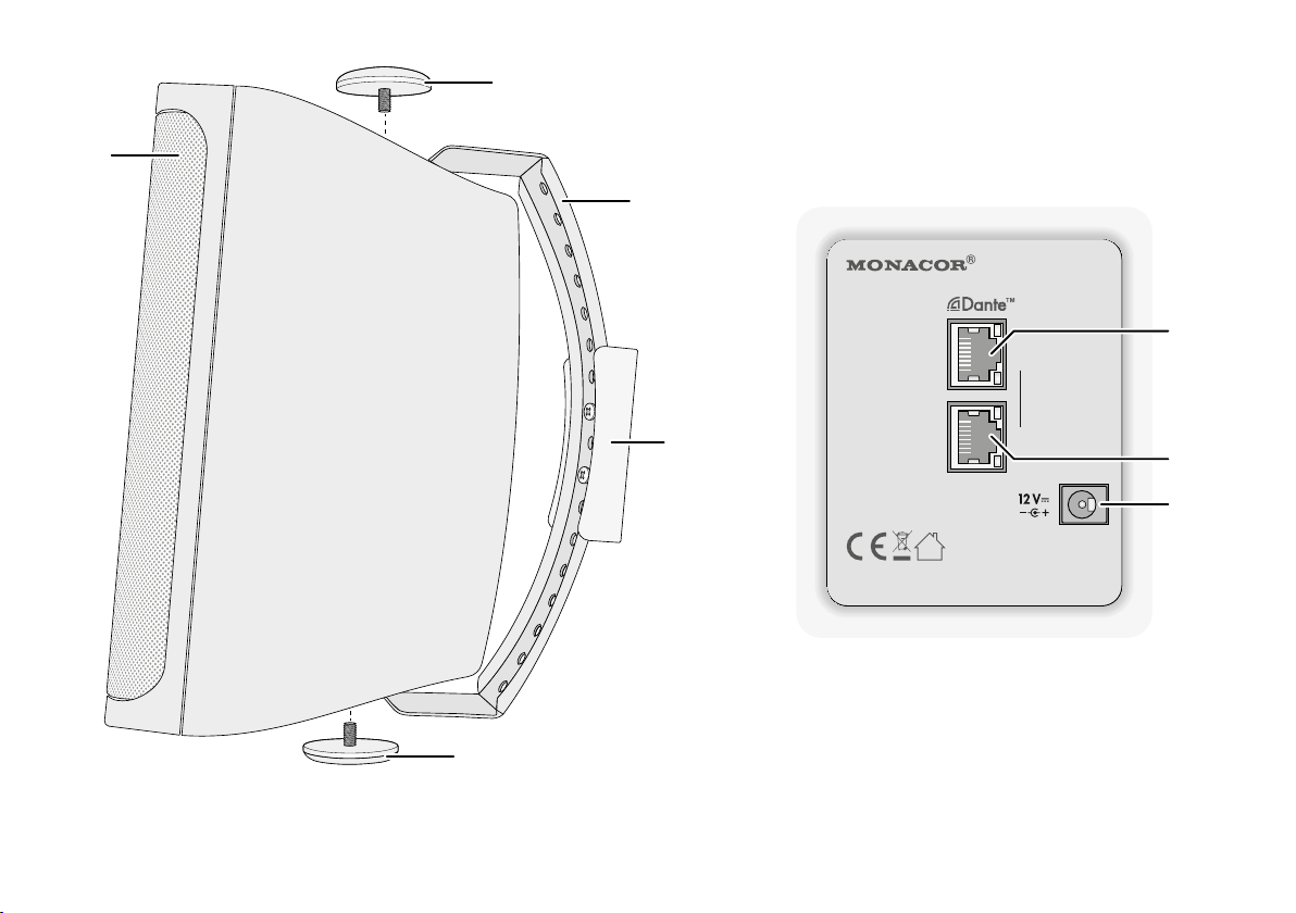
Auf Seite 2 finden Sie alle beschriebenen Montageteile und Anschlüsse.
1 Übersicht der Montageteile undAnschlüsse
1 Lautsprecher
2 Feststellschrauben
3 Metallbügel
4 Kunststoffhalterung
5
RJ45-Buchse IN / PoE zur Verbindung des Lautsprechers mit dem Netzwerk (Ethernet) und zur Stromversorgung des Lautsprechers über
das Netzwerk (z. B. über einen Netzwerk-Switch mit PoE-Speisung).
Die beiden LEDs an der Buchse signalisieren den Verbindungsaufbau und den Datenverkehr.
6
RJ45-Buchse LINK zur Weiterführung der Netzwerkverbindung
z. B. an einen weiteren WALL-05DT
Die PoE-Stromversorgung wird über diese Buchse jedoch nicht
weitergeleitet. Die beiden LEDs an der Buchse signalisieren den
Verbindungsaufbau und den Datenverkehr.
7
Stromversorgungsbuchse zum Anschluss eines 12-V-Netzgeräts
alternativ zur PoE-Versorgung über den Netzwerkanschluss (5)
2 Wichtige Hinweise
Das Gerät entspricht allen relevanten Richt linien der EU und ist deshalb
mit gekennzeichnet.
Verwenden Sie das Gerät nur im Innenbereich und schützen Sie es
•
vor Tropf- und Spritzwasser sowie vor hoher Luftfeuchtigkeit. Der
zulässige Einsatztemperaturbereich beträgt 0 – 40 °C.
Verwenden Sie für die Reinigung nur ein trockenes, weiches Tuch,
•
niemals Wasser oder Chemikalien.
Wird das Gerät zweckentfremdet, nicht richtig angeschlossen, falsch
•
bedient oder nicht fachgerecht repariert, kann keine Haftung für daraus resultierende Sach- oder Personenschäden und keine Garantie
für das Gerät übernommen werden. Ebenso kann keine Haftung für
durch Fehlbedienung oder durch einen Defekt entstandene Datenverluste und deren Folgeschäden übernommen werden.
Deutsch
Soll das Gerät endgültig aus dem Betrieb genommen werden, übergeben Sie es zur umweltgerechten Entsorgung
einem örtlichen Recyclingbetrieb.
5
Page 6

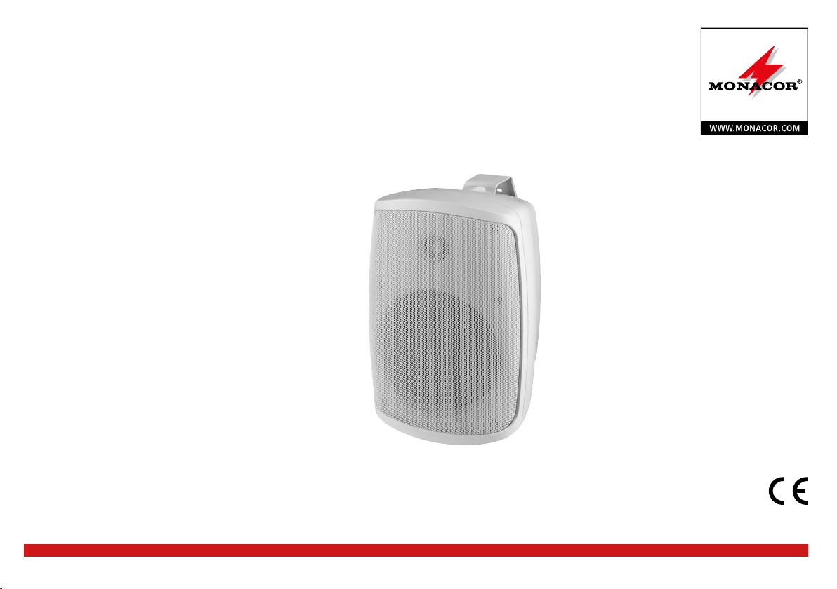
3 Einsatzmöglichkeiten
Der kompakte Aktivlautsprecher WALL-05DT ist für vielfältige Beschallungsaufgaben geeignet, besonders für die Festinstallation (z. B.
Deutsch
zur Hintergrundbeschallung und für Durchsagen). Er ist als 2-Wege-System ausgeführt mit jeweils einem eigenen Verstärker für den
Hochton- und Tieftonbereich. Der Lautsprecher verfügt über eine
Ethernet-Schnittstelle zum Anschluss an ein Dante-Audionetzwerk, aus
dem Audiosignale über einen oder zwei Kanäle empfangen werden
können. Gleichzeitig ist über diese Schnittstelle die Steuerung des
internen Signalprozessors möglich. Über einen Computer lassen sich
im Signalprozessor folgende Funktionen konfigurieren.
Für jeden der beiden Eingangskanäle separat:
– Verstärkung (GAIN)
– Stummschaltung (MUTE)
–
parametrischer Equalizer (PEQ) mit 10 Filtern und 8 Filtercharak-
teristiken
– Peak-Limiter
Für beide Eingangskanäle gemeinsam:
–
Signalverzögerung (DELAY), als Zeit (ms /s) oder Entfernung (mm /m /
mil / inch /feet) einstellbar
–
Hochpassfilter (LOW CUT) mit 10 Filtercharakteristiken unterschied-
licher Flankensteilheit
–
Kopplungsmöglichkeit der Einstellungen beider Eingangskanäle (LINK)
Verschiedene Konfigurationen können im WALL-05DT gespeichert
und bei Bedarf wieder abgerufen werden. Eine Fernbedienung über
einen Tabletcomputer oder ein Smartphone ist möglich.
Die Stromversorgung des Lautsprechers kann über den Netzwerkanschluss erfolgen (Power over Ethernet) oder über ein zusätzliches
Netzgerät.
3.1 Dante
Dante ist ein von der Firma Audinate entwickeltes Audionetzwerk, bei
dem es möglich ist, bis zu 512 Audiokanäle gleichzeitig zu übertragen.
Dante (Digital Audio Network Through Ethernet) nutzt einen verbrei-
teten Ethernet-Standard und basiert auf dem Internet-Protokoll. Die
Übertragung der Audiosignale erfolgt unkomprimiert, synchronisiert
und mit nur minimaler Latenz. Der Vorteil gegenüber analoger Audiosignalübertragung ist eine kostengünstige Verbindung der Komponenten über Standard-Netzwerkkabel und eine geringe Störanfälligkeit
auch bei langen Übertragungsstrecken. Zudem kann die Signalführung
zwischen einmal miteinander verbundenen Komponenten jederzeit per
Software geändert werden. Als Signalquellen dienen im Dante-Netzwerk Geräte, die als Sender (Transmitter) eingerichtet sind. Über das
Programm „Dante Virtual Soundcard“ der Firma Audinate lassen sich
auch Computer als Signalquellen verwenden, um z. B. auf dem Computer abgespielte Audiodateien in das Dante-Netzwerk einzuspeisen.
Der Lautsprecher WALL-05DT ist mit zwei Dante-Empfangskanälen ausgestattet, deren Signale sich im internen Signalprozessor
nach Bedarf mischen lassen. Die Zuordnung der Empfangskanäle zu
zwei beliebigen Sendekanälen im Dante-Netzwerk erfolgt über das
Dante-Konfigurationsprogramm „Dante Controller“ (☞Kap. 5).
Dante™ ist eine Handelsmarke von Audinate Pty Ltd.
6
Page 7

4 Lautsprecher montieren und anschließen
Der Lautsprecher ist für die Wandmontage vorgesehen, kann aber
auch als frei stehendes Gerät verwendet werden.
Zur Montage des Lautsprechers:
1) Die Kunststoffhalterung (4) vom Metallbügel (3) trennen und mit
zwei Schrauben an der gewünschten Montagestelle (z. B. Wand
oder Decke) befestigen.
2) Den Metallbügel (3) mit seinen beiden Kreuzschlitzschrauben an
der Kunststoffhalterung befestigen. Dafür die für die gewünschte
Ausrichtung des Lautsprechers am besten geeigneten Löcher im
Metallbügel wählen.
3) Den Lautsprecher (1) mit den Schrauben (2) am Metallbügel befestigen. Vor dem Festdrehen der Schrauben den Lautsprecher auf
den Beschallungsbereich ausrichten.
4.1 Netzwerk
Zur Konfiguration des Signalprozessors und zum Einspeisen der Audiosignale über ein Dante-Netzwerk die Buchse IN / PoE (5) mit einem
einzelnen Computer, einem lokalen Computernetzwerk oder, z. B. über
einen Router, mit größeren Computernetzwerken verbinden. Für die
korrekte Einrichtung sind unbedingt Netzwerktechnik-Kenntnisse erforderlich. Die Stromversorgung des Lautsprechers kann über dieselbe
Anschlussbuchse erfolgen, wenn diese mit einem Netzwerkelement
verbunden wird, das „Power over Ethernet“ zur Verfügung stellt (z. B.
PoE-Switch).
Für die Einbindung in ein Dante-Netzwerk muss der Lautsprecher
mindestens mit einem Fast-Ethernet-Switch (100-Mbit /s-Ethernet)
verbunden sein.
Auch wenn die DSP-Steuerung und die Einspeisung der Dante- Signale
über dieselbe Anschlussbuchse des WALL-05DT erfolgt, handelt es sich
intern um zwei getrennte Ethernet-Schnittstellen mit unterschiedlichen
IP-Adressen.
Hinweis: Bei einer manuellen Festlegung der IP-Adressen im lokalen Netzwerk
dürfen diese beiden Schnittstellen nicht dieselbe Adresse zugewiesen bekommen!
Die DSP-Schnittstelle des WALL-05DT ist auf den automatischen Erhalt
einer IP-Adresse voreingestellt. Ist in dem angeschlossenen Netzwerk
ein DHCP-Server vorhanden, erhält der Lautsprecher seine Adresse
von ihm. Wird der Lautsprecher über einen einfachen Ethernet-Switch
mit einem Computer verbunden, der ebenfalls auf den automatischen Erhalt einer Adresse eingestellt ist und es ist kein DHCP-Server
vorhanden, weisen sich die Geräte gegenseitig eine Adresse im Bereich 169.254.0.0 – 169.254.255.255 zu. Dies kann unter Umständen
(abhängig von dem verwendeten Computersystem) einige Minuten
dauern. Um die Verbindung ohne DHCP-Server zu beschleunigen,
für den Computer eine Adresse in diesem Bereich festlegen und die
Subnetzmaske auf 255.255.0.0 einstellen.
Die Netzwerk einstellungen der DSP-Schnittstelle können einfach
über das Menü des Steuerprogramms geändert werden. Es ist dort
auch möglich, dem Lautsprecher eine feste IP-Adresse zuzuweisen
(☞Kap. 7.11).
Hinweis: Soll der DSP des WALL-05DT in größeren Netzwerken mit dem Steuerprogramm konfiguriert werden, so kann es bei einem höheren Datenaufkommen
(z. B. wenn mehrere Dante-Transmit-Channels als Multicast-Flows eingestellt sind)
zur Störung der Steuerverbindung kommen. In diesem Fall kann es notwendig
werden, dem WALL-05DT einen Switch vorzuschalten, der „IGMP Snooping“
(IGMP = Internet Group Management Protocol) unterstützt. Der Switch kann so
konfiguriert werden, dass er den WALL-05DT entlastet, indem er nur MulticastDaten an den WALL-05DT weiterleitet, wenn solche von ihm angefordert wurden.
Deutsch
7
Page 8
Die Dante-Schnittstelle des Lautsprechers ist ebenfalls für eine automatische Adressvergabe voreingestellt und kann über das Programm
„Dante Controller“ konfiguriert werden. Die Installation dieses Programms ist in Kapitel 5 beschrieben.
Deutsch
Die Buchse LINK (6) kann zur Weiterführung der Netzwerkverbindung, z. B. direkt an einen weiteren WALL-05DT, genutzt werden.
Die PoE-Stromversorgung wird über diese Buchse jedoch nicht weitergeleitet.
4.2 Stromversorgung
Die Stromversorgung kann über den Netzwerkanschluss erfolgen
(Power over Ethernet). Dazu die Buchse IN / PoE (5) mit einem Netzwerkanschluss verbinden, der PoE liefert (z. B. PoE-Switch). Eine höhere
Ausgangsleistung kann jedoch über eine zusätzlich angeschlossene
Stromversorgung erzielt werden. Ist keine Versorgung über PoE möglich oder wird die maximale Ausgangsleistung benötigt, ein Netzgerät
mit einer stabilisierten Gleichspannung von 12 V und einer Dauerbelastbarkeit von 2 A über einen Hohlstecker mit den Maßen 5,5 / 2,1 mm
(Außen-/ Innendurchmesser) an die Buchse 12 V ⎓ (7) anschließen.
Dabei die Polarität beachten: Innenkontakt = +.
Für die Stromversorgung eignet sich z. B. das Netzgerät PSS-1230DC
von MONACOR.
5 Dante-Netzwerk einrichten
Die Einrichtung des WALL-05DT als Empfänger im Dante-Netzwerk
geschieht über das Programm „Dante Controller“, das über die Website der Firma Audinate kostenlos erhältlich ist. Die über das Programm
vorgenommenen Einstellungen werden in den beteiligten Sendern und
Empfängern des Dante-Netzwerks gespeichert, sodass das Programm
nur für die Konfiguration des Netzwerks, nicht aber während des
normalen Betriebs erforderlich ist. Für den Computer, auf dem das
Programm „Dante Controller“ laufen soll, gelten folgende Systemvoraussetzungen:
Komponente Mindestvoraussetzungen
Prozessor 1 GHz
Arbeitsspeicher 512 MByte
Netzwerk
Betriebssystem
Abb. 3 Systemvoraussetzungen für „Dante Controller“
Windows ist ein registriertes Warenzeichen der Microsoft Corporation in den USA
und anderen Ländern. Mac OS ist ein registriertes Warenzeichen von Apple Computer, Inc. in den USA und anderen Ländern.
5.1 Installation des Programms „Dante Controller“
Zur Installation des Programms von der Audinate-Website:
1) Die folgende Internet-Adresse aufrufen:
https://www.audinate.com/products/software/dante-controller
2) Dort das Betriebssystem auswählen.
Standard-Ethernet-Schnittstelle (100 Mbit /s oder Gigabit) oder
Wireless-LAN-(Wi-Fi-)Schnitt stelle
Windows 7 (SP1 oder höher), 8.1 oder 10
Hinweis: Sowohl UTF-8 als auch Unicode werden unterstützt, außer
für Host- und Gerätenamen; der DNS-Standard unterstützt Unicode
für diese nicht.
Mac OS X 10.9.5, 10.10.5 oder 10.11
Hinweis: Nur Intel-Architektur, PPC-Architektur wird nicht unterstützt.
8
Page 9
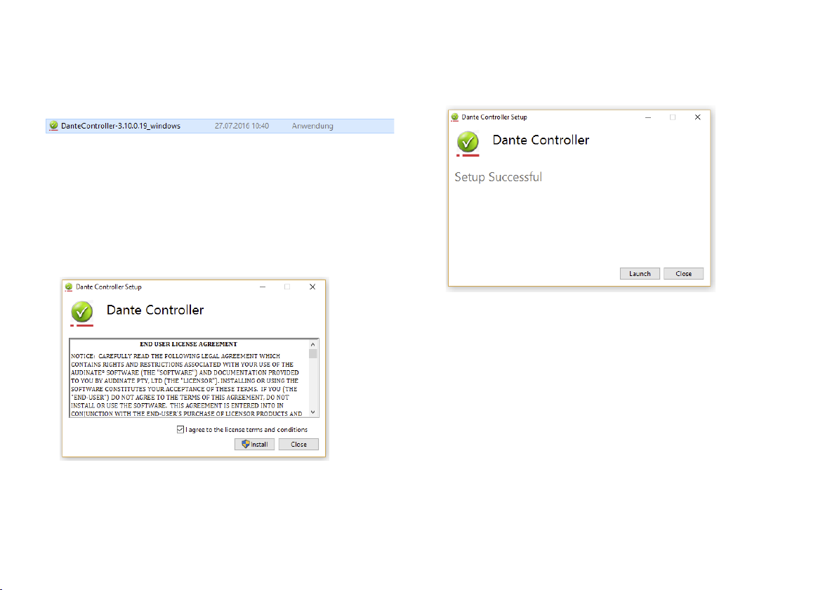
3) Den Button mit der Dante-Controller-Version anklicken.
4) Einloggen bzw. einen Account erstellen.
5) Die Software herunterladen.
6) Das Installationsprogramm (Dante-Setup) starten.
Abb. 4 Beispiel: Installationsdatei für Windows
7) Den Anweisungen des Installationsprogramms folgen:
a) Den im „Dante Controller Setup“-Fenster aufgeführten Lizenz-
text durchlesen.
b) Durch Anklicken der Check-Box „I agree …“ die Lizenzverein-
barung akzeptieren oder die Installation mit dem„ Close“-Button
abbrechen.
c) Auf den „Install“-Button klicken.
e)
Das „Dante Controller Setup“-Fenster mit der angezeigten
Nachricht „Setup Successful“ durch Anklicken des „Close“-Buttons schließen oder alternativ die Dante-Controller-Software
durch Anklicken des „Launch“-Buttons starten.
Abb. 6 Dante-Controller – „Setup Successful“
Deutsch
Abb. 5 Dante-Controller Lizenzvereinbarung
d)
Die folgenden Betriebssystemwarnungen zur Kenntnis nehmen
und akzeptieren.
9
Page 10
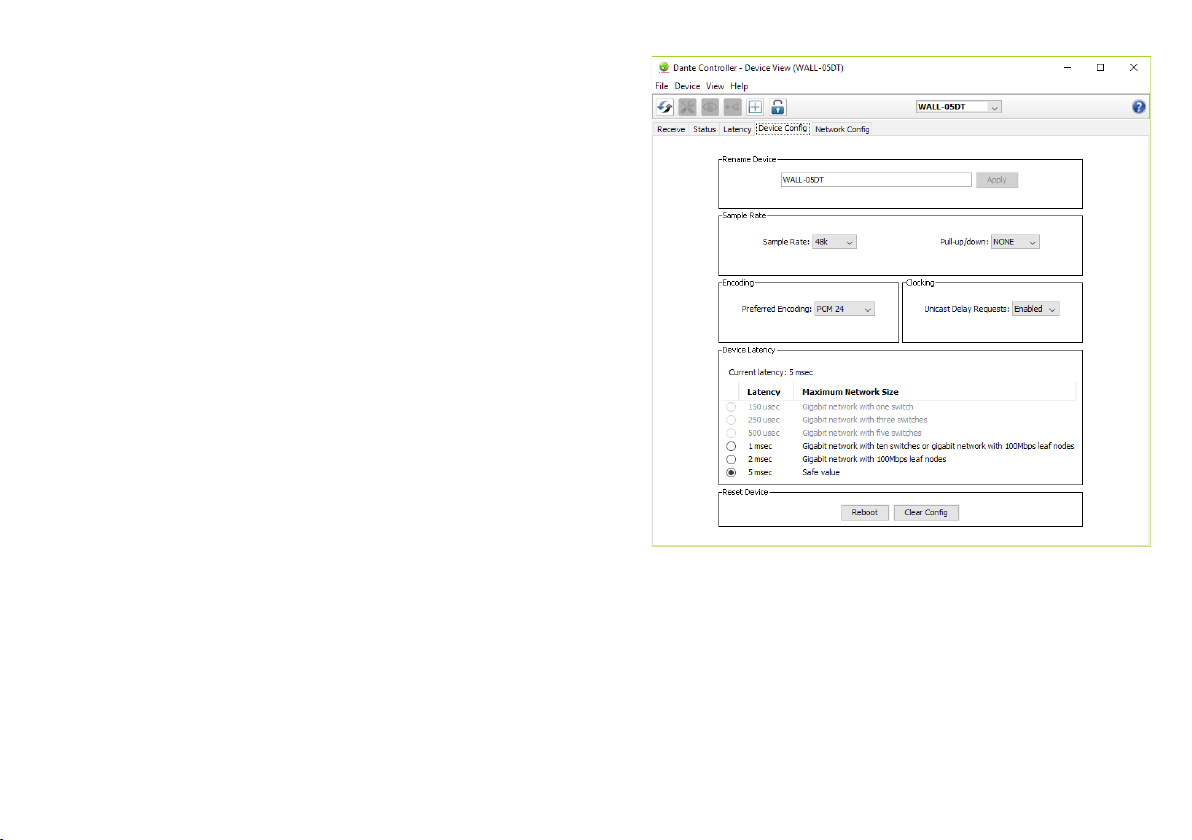
5.2 Gerätekonfiguration mit dem Dante-Controller
1) Den Dante-Controller starten.
2) Warten bis in der Matrix der gewünschte Dante-Transmitter und
Deutsch
der WALL-05DT (unter „Dante Receivers“) erscheinen.
Hinweis: Ein Nichterscheinen des WALL-05DT bzw. des Dante-Transmitters
kann als Grund haben, dass dasjenige Gerät nicht eingeschaltet ist, sich in
einem anderen Subnetz befindet oder sich nicht mit den anderen DanteGeräten synchronisieren kann. Für einen der beiden zuletzt genannten Gründe
sollte das Dante-Gerät aber zumindest unter dem Reiter „Device Info“ oder
„Clock Status“ im Network-View aufgeführt werden. Ein Ausschalten des
Geräts oder die Verbindungstrennung zum Switch könnte eine schnelle Lösung
des Problems bewirken. Weitere Informationen befinden sich im Benutzerhandbuch des Dante-Controllers von Audinate.
3)
In der Menüleiste des Dante-Controllers „Device / Device View“
auswählen oder die Tastenkombination Strg+D drücken. Das
Device-View-Fenster öffnet sich.
4) In der unter der Menüleiste erscheinenden Leiste im Drop-DownMenü den „WALL-05DT“ auswählen.
5) In der dritten Leiste lassen sich unterschiedliche Informationen zu
dem Gerät anzeigen und Einstellungen vornehmen. Den Reiter
„Device Config“ auswählen (siehe Abbildung 7).
6) Bei Bedarf die „Sample Rate“ an den gewünschten Dante-Transmitter anpassen oder eine andere gemeinsame Sample-Rate für
beide Geräte festlegen.
7)
Im Feld „Rename Device“ kann der Name, der im Dante-Netzwerk
für das Gerät verwendet wird, geändert werden (z. B. auf einen
eindeutigen Namen mit einem Bezug auf den Installationsort). Eine
Änderung mit „Apply“ bestätigen.
Abb. 7 Device-View vom WALL-05DT
8)
Über den Reiter „Network Config“ lassen sich bei Bedarf die Netzwerkeinstellungen für die Dante-Schnittstelle des WALL-05DT ändern.
10
Page 11
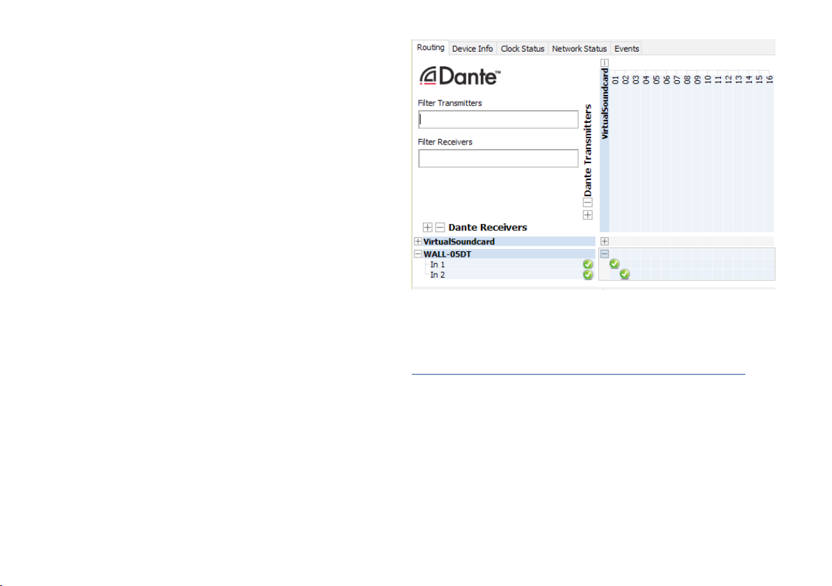
5.3 Routing mit dem Dante-Controller
Für die Zuweisung der Eingangs- und Ausgangssignale der beteiligten
Geräte:
1) Im „Network View“-Fenster unter „Routing“ die Kanäle des gewünschten Dante-Transmitters unter „Dante Transmitters“ sowie
die Kanäle des WALL-05DT unter „Dante Receivers“ durch Klicken
auf das ⊞ öffnen.
2)
Ausgehend vom Dante-Transmit-Kanal bis zur Zeile des gewünschten Dante-Receive-Kanals vom WALL-05DT navigieren und auf das
Feld klicken.
3)
Warten bis das Feld einen grünen Kreis mit weißem Haken anzeigt
(siehe Abbildung 8).
4) Die letzten zwei Schritte optional für den zweiten Dante-Re ceiveKanal des WALL-05DT vornehmen.
Deutsch
Abb. 8 Audio-Routing von der Tonquelle „VirtualSoundcard“
zum Empfänger „WALL-05DT“
Auf der Audinate-Website kann zum Dante-Controller ein englisches
Benutzerhandbuch (User Guide) heruntergeladen werden unter:
https://www.audinate.com/resources/technical-documentation
11
Page 12

6 Bedienung
Der Lautsprecher verfügt über keinerlei Bedienelemente. Sein Signalprozessor (DSP) wird ausschließlich über das Netzwerk von einem
Deutsch
Computer aus ferngesteuert (☞Kap. 7). Zudem ist eine Bedienung
über einen Tabletcomputer sowie eine eingeschränkte Steuerung von
Lautsprechergruppen per Smartphone möglich (☞Kap. 9).
In jedem Fall ist zu beachten, dass der zur Verfügung stehende
Funktionsumfang von den Zugriffsrechten des Benutzers abhängt.
Diese sind in Zugriffsebenen (☞Kap. 6.1) festgelegt, die sich nach
Bedarf konfigurieren lassen.
6.1 Zugriffsebenen
Sollten sich nicht alle in der Anleitung beschriebenen Bedienvorgänge
durchführen lassen, sind möglicherweise eingeschränkte Zugriffsrechte
die Ursache.
Für die Konfiguration des Geräts stehen drei Zugriffsebenen mit
unterschiedlichen Rechten zur Verfügung. Der Zugang zu den Ebenen
„Administrator“ und „User“ wird über unterschiedliche Passwörter
erreicht.
Die folgende Tabelle zeigt die Zugriffsebenen in absteigender Rangfolge und die zugehörigen Passwörter.
Zugriffsebene Passwort *
Administrator mega_adm
User monacor
Locked State —
Abb. 9 Passwortvorgaben
* Diese Passwörter sind vom Werk vorgegeben und können vom Anwender in der
jeweiligen Zugriffsebene geändert werden. Geänderte Passwörter gut merken!
Die Passwörter sind im Lautsprecher gespeichert. Nach dem Einschalten ist dieser generell in der Ebene „User“. Um während des Betriebs
die Ebene zu wechseln, das entsprechende Passwort über den Menüpunkt „Hardware Enter Password“ des Steuerprogramms eingeben
(☞Kap. 7.4.1) oder den „ Locked State“ über den Menüpunkt „Hardware Lock Unit“ (☞Kap. 7.5) aufrufen.
In der Zugriffsebene „Administrator“ können die Bedienmöglich-
keiten der niedrigeren Ebenen eingeschränkt werden (☞Kap. 7.4.3).
6.2 Inbetriebnahme
Wenn nicht bekannt ist, mit welchen Einstellungen der Lautsprecher
nach dem Einschalten der Stromversorgung startet, zuvor die Tonquellen am Dante-Netzwerk auf eine niedrige Lautstärke einstellen.
Damit wird eine unerwünscht hohe Einschaltlautstärke vermieden.
Nach dem Einschalten der Stromversorgung werden die Einstellungen
des letzten Betriebs geladen oder ein für das Einschalten festgelegtes
Preset (☞Kap. 7.7).
12
Page 13
7 Das DSP-Steuerprogramm
7.1 Installation der PC-Software
Die benötigte Software können Sie auf unserer Website im Bereich
„Service / Downloads“ herunterladen:
https://www.monacor.com/de-de/monacorinternational/service/
Diese Anleitung bezieht sich auf die Version 3.8.22 der PC-Software.
Systemvoraussetzung für die Installation des DSP-Steuerprogramms
ist ein Computer mit dem Betriebssystem WindowsXP mit Service
Pack2 oder einer höheren Windows-Version oder Mac OS X ab Version 10.5.8 und einer Ethernet-Schnittstelle. Die Bildschirmauflösung
sollte mindestens 1024 × 768 Bildpunkte betragen.
–
Für die Installation der PC-Software auf einem Windows-System das passende Installationsprogramm „MONACOR_DSP_Controller […] .msi“
starten und den Anweisungen des Instal lationsprogramms folgen.
– Auf einem Computer mit einem Mac-OS-X-System das Programm
„MONACORDSPController.app“ starten.
7.2 Steuerprogramm aufrufen
1) Auf dem Computer das Steuerprogramm „DSP Controller“ aufrufen.
2)
Wurde für das Programm ein Passwort eingerichtet (☞Kap. 7.2.2),
erscheint ein Fenster zur Eingabe des Passworts. Das Passwort
eingeben.
Bei falsch eingegebenem Passwort erscheint die Meldung „Invalid password!“. In diesem Fall die Meldung bestätigen und das
Passwort erneut eingeben.
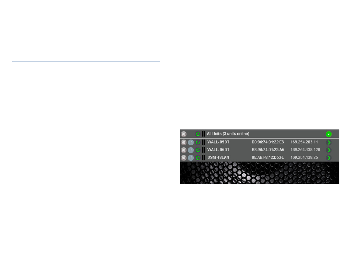
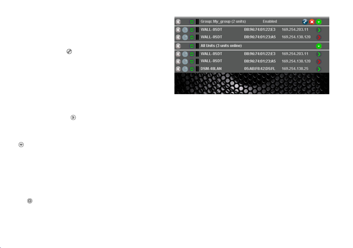
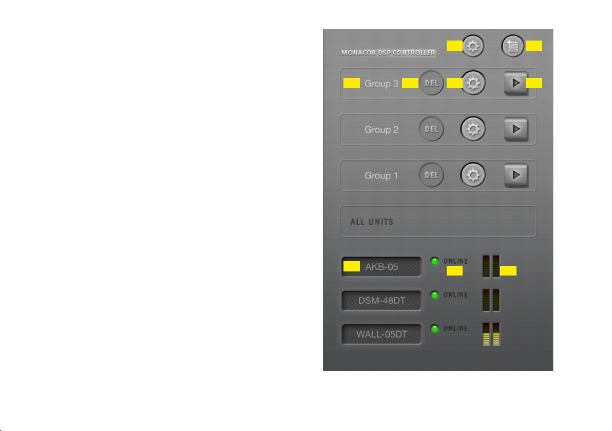
Das Übersichtsfenster (Abb. 10) wird angezeigt. Darin erscheint eine
Liste aller verbundenen Geräte. In der oberen Zeile „All Units“ wird
in Klammern angegeben, wie viele Geräte momentan „online“ sind,
d. h. in aktiver Verbindung mit dem Computer stehen. Darunter gibt
es für jedes Gerät eine Zeile mit verschiedenen Informationen und
Funktionen.
Abb. 10 Übersichtsfenster
Hinweis: Mit dem Programm „DSP Controller“ lassen sich nicht nur die Lautsprecher vom Typ WALL-05DT steuern, sondern noch weitere Geräte von MONACOR
mit integriertem Signalprozessor. In der Abbildung ist daher auch ein DSM-48LAN
aufgeführt.
Deutsch
13
Page 14

Beschreibung der Funktionen:
1. Schaltfläche zum Stummschalten des Geräts
Während der Stummschaltung ist die Schaltfläche rot. Zum Wie-
Deutsch
dereinschalten des Tons erneut auf die Schaltfläche klicken. Das
Klicken auf die Schaltfläche in der Zeile „All Units“ führt zur
gleichzeitigen Stummschaltung aller verbundenen Geräte.
2. Schaltfläche zum Identifizieren eines Geräts
Nach dem Klicken auf die Schaltfläche blinkt diese für einige Se-
kunden und mit ihr alle LEDs am Gerät.
3. Symbol für den Betriebszustand des Geräts
Grün = Betrieb
Rot = Bereitschaftsmodus (Standby)
Grau = Verbindung unterbrochen
Durch Klicken auf das Symbol lässt sich zwischen Betriebs- und
Bereitschaftsmodus umschalten. Während beim Einschalten eines
Geräts eine neue Verbindung aufgebaut wird, erscheint am Ende
der Liste vorübergehend eine zusätzliche Zeile „Startup…“ mit
dem Symbol .
4.
Die beiden senkrechten Balken stellen eine einfache Pegelanzeige für den Eingang und den Ausgang eines Geräts dar.
5. Anzeige des Gerätenamens
Der voreingestellte Name kann zur Unterscheidung gleicher Geräte
hier oder im Konfigurationsfenster (☞Kap. 7.3.2) geändert werden.
Es bietet sich an, den gleichen Namen wie im Dante-Netzwerk zu
verwenden.
6.
Anzeige der Hardware-Adresse (MAC-Adresse) der Schnittstelle des
Geräts, über die sich ein Gerät immer eindeutig identifizieren lässt
7. Anzeige der IP-Adresse eines Geräts
Bei unterbrochener Verbindung steht an dieser Stelle „Offline“.
8. Schaltfläche zum Aufruf des Konfigurationsfensters (Abb. 13)
für ein Gerät, das „online“ ist
In der Zeile „All Units“ kann über die Schaltfläche die Liste der
Geräte ausgeblendet oder über wieder eingeblendet werden.
7.2.1 Gerätegruppen
Mehrere Geräte können zur ge meinsamen Steuerung in Gruppen
zusammengefasst werden. Sie können so z. B. ge meinsam stummgeschaltet werden. Welche Parameter der gruppierten Geräte gemeinsam gesteuert werden, lässt sich in den Einstellungen der
Gruppe festlegen. Alle Aktionen einer Gruppe setzen voraus, dass
die Gruppenmitglieder mit den nötigen Zugriffsrechten geladen sind.
Es gibt drei Gruppentypen:
„Carbon Copy“: Alle Einstellungen im Konfigurationsfenster der Grup-
pe oder eines Gruppenmitglieds werden von allen
Gruppenmitgliedern übernommen, mit Ausnahme
der unter „Exceptions“ definierten Parameter.
„Advanced“: Nur die Einstellungen der unter „Setup Links“ de-
finierten Parameter werden von den Gruppenmitgliedern übernommen.
„Master Volume“: Nur grundlegende Einstellungen, wie die Gesamt-
lautstärke und eine einfache Klangeinstellung, lassen sich gemeinsam durchführen (☞Kap. 7.3.4).
7.2.1.1 Neue Gruppe bilden
1) Zum Anlegen einer neuen Gruppe den Menüpunkt „Tools New
Group“ aufrufen.
14
Page 15
2) Im angezeigten Fenster in das Feld „Enter the name of the new
group:“ den gewünschten Gruppennamen eingeben.
In der Liste wird jetzt eine zusätzliche Zeile für die Gruppe
gezeigt (Zeile „Group: …“, ☞ Abb. 11).
3)
Über die Schaltfläche kann eine Gruppe eingerichtet oder geändert werden. Es können Mitglieder zugefügt oder entfernt werden
(Members: Select …) und es lassen sich Gruppenname, Gruppentyp
und Kopplungseigenschaften ändern. Eine Gruppe kann zudem
vorübergehend deaktiviert (disabled) oder wieder aktiviert (enabled)
werden. Zudem besteht die Möglichkeit, einen Beschreibungstext
zur Gruppe einzugeben.
In der Zeile „Group: …“ wird nach dem Gruppennamen die
aktuelle Anzahl der Gruppenmitglieder angezeigt (units).
4)
Über die Schaltfläche am Ende der Zeile „Group: …“ kann
das Konfigurationsfenster der Gruppe aufgerufen werden. Ist das
Konfigurationsfenster der Gruppe bereits geöffnet, kann über diese
Schaltfläche eine Liste aller Gruppenmitglieder gezeigt oder über
wieder ausgeblendet werden (ggf. per Doppelklick). Während
die Konfigurationsfenster der Gruppentypen „Carbon Copy“ und
„Advanced“ denen für einzelne Geräte gleichen (☞Kap. 7.3.2
und 7.3.3), haben Gruppen vom Typ „Master Volume“ ein spezielles
Fenster für die Steuerung (☞Kap. 7.3.4).
7.2.1.2 Gruppe löschen
Zum Löschen einer Gruppe in der entsprechenden Zeile auf die Schaltfläche klicken (☞ Abb. 11). Es erscheint eine Sicherheitsabfrage
zur Bestätigung des Löschvorgangs. Wenn der Gruppe zu diesem
Zeitpunkt Geräte zugeordnet sind, er scheint eine zusätzliche Sicherheitsabfrage.
Abb. 11 Übersichtsfenster mit Gruppe
7.2.2 Programmpasswort einrichten
Um einen Passwortschutz für den Start des Programms einzurichten:
1) Den Menüpunkt „Tools Set Software Password“ aufrufen.
2)
Im angezeigten Fenster in das Feld „Enter New Password:“ das
gewünschte Passwort eingeben.
3) Im anschließend angezeigten Fenster in das Feld „Confirm New
Password:“ das Passwort zur Bestätigung noch einmal eingeben
und gut merken!
7.2.3 Programmpasswort ändern
Um das Passwort für den Start des Programms zu ändern:
1) Den Menüpunkt „Tools Change Software Password“ aufrufen.
2)
Im angezeigten Fenster in das Feld „Enter Old Password:“ das
bisherige Passwort eingeben.
3) Im nun angezeigten Fenster in das Feld „Enter New Password:“
das neue Passwort eingeben.
Deutsch
15
Page 16

4) Im anschließend angezeigten Fenster in das Feld „Confirm New
Password:“ das neue Passwort zur Bestätigung noch einmal eingeben und gut merken!
Deutsch
7.2.4 Demo-Modus
Auch wenn kein Gerät mit dem Computer verbunden ist, lässt sich
zu Demonstrationszwecken ein virtuelles Gerät erzeugen. Dazu den
Menüpunkt „Tools Enter Demo Mode“ aufrufen.
In der Liste erscheinen jetzt verschiedene virtuelle Geräte mit der
zusätzlichen Bezeichnung „DEMO…“. Wie bei realen Geräten kann
hier über die Schaltfläche das Konfigurationsfenster aufgerufen
werden (☞Abb. 13).
Um die virtuellen Geräte wieder aus der Liste zu entfernen, den
Menüpunkt „Tools Leave Demo Mode“ aufrufen.
7.2.5 Firmware Update
Für eine reibungslose Kommunikation zwischen dem Steuerprogramm
und einem Gerät müssen beide zueinander passende Versionen haben.
Liegt das Steuerprogramm in einer neueren Version vor, kann die
Firmware (Be triebssystem) der Geräte über das Steuerprogramm aktualisiert werden. Dabei gehen alle in den Geräten gespeicherten
Einstellungen verloren. Sollen die Einstellungen erhalten bleiben, müssen sie vor der Aktualisierung auf dem Computer gesichert werden
(☞Kap. 7.8 und 7.10).
Hinweis: Eine Firmware-Aktualisierung geschieht auf eigenes Risiko. Nach einem
Update kann die Funktionsweise des Geräts von der Beschreibung in
der Bedienungsanleitung abweichen.
VORSICHT: Schalten Sie die Signalquellen aus oder reduzieren Sie
deren Ausgangspegel, damit es nach dem Zurücksetzen der Einstellungen nicht zu unerwartet hoher Lautstärke kommt.
Um die Firmware eines Geräts auf den neuesten Stand zu bringen, den
Menüpunkt „Tools Enable Update“ aufrufen. Hinter den Geräten in
der Liste wird jetzt das Symbol angezeigt. Bei einem grauen Symbol
ist kein Update möglich (z. B. weil die Firmware des Geräts bereits
aktuell ist oder weil die Zugriffsrechte für das Update nicht ausreichen).
Ist das Symbol orange, kann ein Update erfolgen:
1)
In der Zeile des gewünschten Geräts auf die Schaltfläche klicken.
2) Es erscheint ein Hinweis, dass das Gerät während der mehrschrittigen Aktualisierung nicht ausgeschaltet oder die Verbindung getrennt werden darf. Schlägt die Aktualisierung fehl, muss sie erneut
gestartet werden.
Die Aktualisierung mit [OK] starten oder mit [Cancel] abbrechen.
3) Nach erfolgter Aktualisierung wird noch eine Meldung angezeigt.
Diese ebenfalls bestätigen.
Um in der Liste die Update-Symbole wieder auszublenden, den Menüpunkt „Tools Disable Update“ aufrufen.
Hinweis: Bei einem Rücksetzen der Einstellungen auf die Werksvorgaben sind
auch die Netzwerkeinstellungen und die Passwörter des Geräts betroffen, d. h. es kann möglicherweise zunächst vom Computer nicht
mehr auf das Gerät zugegriffen werden (vgl. Hinweis in Kapitel 7.2.5.1).
7.2.5.1 Update über das Menü des Konfigurationsfensters
Ein Update der Firmware ist ebenfalls über das Menü des Konfigurationsfensters möglich (Hardware Firmware Update), wenn sich
das Gerät in der Zugriffsebene „Administrator“ befindet oder in der
Zugriffs ebene „User“ und dieser das erforderliche Recht „Upgrade
the unit firmware“ eingeräumt wurde (☞Kap. 7.4.3).
Auf Administrator-Ebene lässt sich außerdem eine beliebige Firmware
manuell auswählen. Unter „File Load Factory Settings“ über das
16
Page 17

Menü des Konfigurationsfensters wird der Datei-Explorer geöffnet.
Eine Flash-Image-Datei (Endung „.ffi“) enthält neben den Presets und
den dazugehörigen Einstellungen und Zugriffsmöglichkeiten auch die
komplette Firmware.
Hinweis zum Laden einer Flash-Image-Datei (*.ffi): Das Laden eines FlashImages bewirkt zuerst ein Firmware-Update und dann das Laden eines FactoryFiles.
Da ein Firmware-Update das Gerät auf eine automatische IP-Adressenzuweisung („Network Settings“ ☞Kap. 7.11) zurückstellt, kann auf ein Gerät, bei
dem zuvor eine feste IP-Addresse eingestellt war, eventuell vom Computer aus
nicht mehr zugegriffen werden. Dies führt dazu, dass das Laden des Flash-Images
aufgrund fehlender Verbindung nicht weiter durchgeführt werden kann.
Wichtig: Vor dem Laden eines Flash-Images sollte darauf geachtet werden,
dass sowohl dem PC-Netzwerkinterface als auch dem Gerät automatisch eine
IP- Adresse zugeordnet worden ist.
7.2.6 Programm beenden
Zum Beenden des Programms den Menüpunkt „File Quit“ aufrufen
oder das Programmfenster schließen.
Deutsch
17
Page 18

7.3 Signalverarbeitung konfigurieren
ACHTUNG Der Signalprozessor ist in Verbindung mit dem Steuer-
Deutsch
Zur Konfiguration des Lautsprechers in der Liste bei dem Lautsprecher
auf die Schaltfläche klicken (☞ Abb. 10, 11).
Das Konfigurationsfenster (Abb. 13) mit der Hauptansicht (MAIN)
wird für das gewählte Gerät angezeigt. Auf der linken Seite wird als
Farbfeld neben UNIT CONNECTION [2] der Verbindungsstatus des
Geräts angezeigt. Bei grünem Feld besteht eine Datenverbindung.
Bei rotem Feld ist die Verbindung unterbrochen, das Ändern einer
Einstellung ist dann nicht möglich. Bei einem Versuch erscheint eine
entsprechende Meldung.
Auf dem Bildschirm geänderte Einstellungen werden bei bestehender Verbindung sofort zum Gerät übertragen. Die Einstellungen
können auf dem Computer und im Gerät (☞Kap. 7.3.2) als Preset
gespeichert werden. Zudem kann festgelegt werden, ob beim Einschalten des Geräts immer ein bestimmtes Preset geladen werden soll oder
der letzte Zustand vor dem Ausschalten (☞Kap. 7.7).
Über die Schaltflächen am oberen Rand [1] kann auf die Ansichten
der Eingangskanäle IN-A und IN-B (Abb. 14) umgeschaltet werden. Dies
ist jedoch nur in der Zugriffsebene „Administrator“ möglich. Über die
Schaltfläche MAIN gelangt man zurück zur Hauptansicht.
programm ein effektives Werkzeug, mit dem sehr feine,
aber auch gravierende Änderungen der Übertragungseigenschaften des Lautsprechers möglich sind.
Jede Änderung der Parameter sollte deshalb mit
Bedacht und Sachverstand vorgenommen werden. Extreme Änderungen der Einstellungen können schlimmstenfalls zur Schädigung des Lautsprechers führen.
7.3.1 Signalweg
In der Abbildung 12 ist der Signalweg durch die Lautsprecherbox
als Blockdiagramm dargestellt. Die beiden aus dem Dante-Netzwerk
kommenden Eingangssignale durchlaufen die folgenden Stationen:
➾ Eingangsverstärker (GAIN)
➾ 10-bandige Klang einstellung (PEQ)
➾ Pegelbegrenzung (LIMITER)
➾ Mischstufe (Summierer)
➾ Signalverzögerung (DELAY)
➾ Hochpassfilter (LOW CUT)
Die darauffolgende Signalverarbeitung (Frequenzweiche, Limiter zum
Schutz gegen Überlastung der Lautsprecher, usw.) ist vom Werk speziell auf den WALL-05DT abgestimmt und für den Anwender nicht
zugänglich.
Die Parameter zu den im grauen Kasten gezeigten Blöcken können
in den Ansichten MAIN, IN-A und IN-B eingestellt werden. Für einige
ist der Zugriff von mehreren Ansichten aus möglich.
Hinweis: Die Einstellmöglichkeiten sind von den Zugriffsrechten der aktuellen
Zugriffsebene ab hängig (☞Kap. 6.1). Um alle Einstellungen durchführen zu können, sollte beim ersten Aufruf des Steuerprogramms in
die Zugriffsebene „Administrator“ gewechselt werden. Von hier aus
können dann, entsprechend dem für die Bedienung des Geräts geplanten Personenkreis, die Zugriffsrechte für die anderen Zugriffsebenen
festgelegt werden (☞Kap. 7.4).
18
Page 19
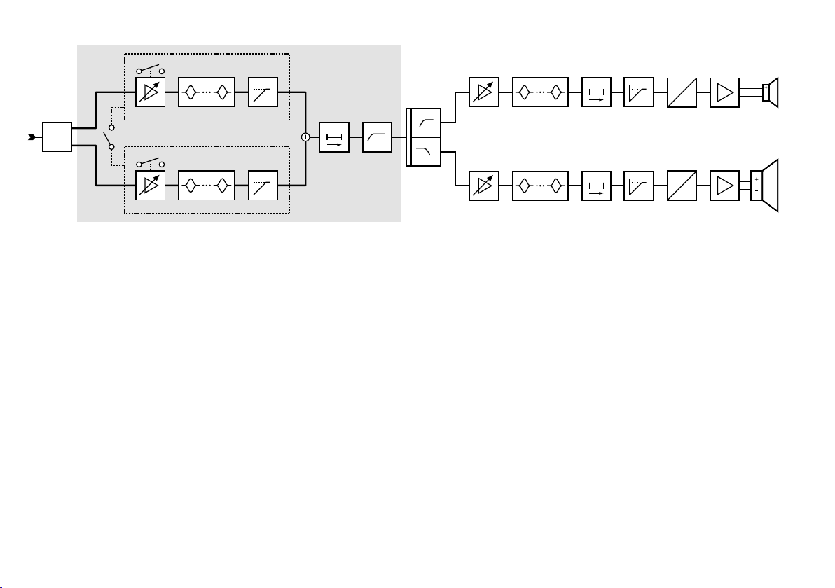
MUTE
IN A
PEQ 1 – 10
1
Dante
2
LINK
MUTE
IN B
PEQ 1 – 10
Abb. 12 Blockdiagramm des Signalwegs
out
in
LIMITERGAIN
LOW CUTDELAY
out
in
LIMITERGAIN
HF
PEQ 1 – 10
CROSSOVER
LF
PEQ 1 – 10
out
LIMITERDELAYGAIN
out
LIMITERDELAYGAIN
D
A
in
D
A
in
Deutsch
19
Page 20

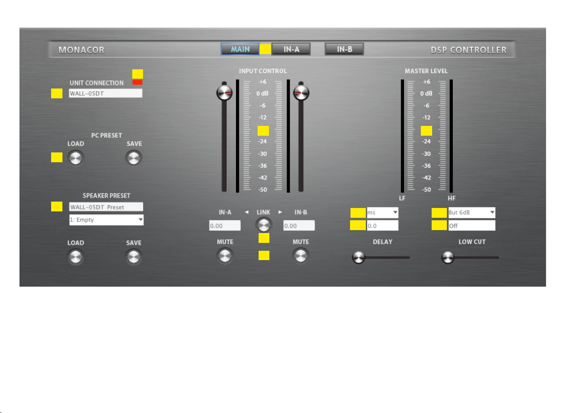
7.3.2 Ansicht MAIN (Abb. 13)
[1]
Schaltflächen zum Umschalten der An sicht (Wechsel der Ansicht
nur in der Zugriffsebene „Administrator“ möglich)
Deutsch
[2] UNIT CONNECTION – Verbindungsstatus
Grün = verbunden
Rot = nicht verbunden
[3] Name des Geräts; kann durch Überschreiben geändert werden
[4] PC PRESET
Speichern „SAVE“ der aktuellen Einstellungen als Preset auf dem
Computer (wie Menüpunkt „File Save“) und Laden „LOAD“
vom Computer (wie Me nüpunkt „File Open“)
[5] SPEAKER PRESET
Speichern „SAVE“ der aktuellen Einstellungen als Preset im Gerät
und Laden „LOAD“ eines im Gerät gespeicherten Presets
Den Speicherplatz im Listenfeld wählen und im oberen Feld einen
Namen eingeben.
Hinweis: Damit ein Preset auch über die Gruppensteuerung wählbar ist,
[6]
Regler INPUT CONTROL zur Verstärkungseinstellung (Lautstärke)
muss es auf einem der Speicherplätze 10 – 19 gespeichert werden.
für die Eingänge, daneben Pegelanzeigen, darunter Eingabe-/ An-
zeigefelder als numerische Eingabemöglichkeit
[7] Pegelanzeigen MASTER LEVEL für die Ausgänge LF (Tieftonlaut-
sprecher) und HF (Hochtonlautsprecher)
[8] LINK-Schalter zur Kopplung (d. h. zur gemeinsamen Steuerung)
der beiden Eingangskanäle
Dabei übernimmt der Kanal IN-B die Einstellungen von Kanal IN-A.
[9] MUTE-Schalter zum Stummschalten des jeweiligen Eingangs
[10]
Listenfeld zum Wählen der Einheit für den DELAY-Wert [11]:
Zeit oder Entfernung (zur automatischen Berechnung der Schalllaufzeit)
[11] Eingabe-/ Anzeigefeld DELAY für die Einstellung einer Signalver-
zögerung der Eingangssignale (z. B. zum Ausgleich von Laufzeitunterschieden durch unterschiedliche Abstände einzelner Lautsprecher zur Hörposition)
Die Signalverzögerung kann alternativ über den Schieberegler
eingestellt werden.
[12] Listenfeld zur Auswahl des Filtertyps für das Hochpassfilter LOW
CUT mit folgenden Optionen:
Anzeige Filtertyp Steilheit
But 6dB Butterworth 6 dB/Oktave
Bes 6dB Bessel 6 dB/Oktave
But 12dB Butterworth 12 dB/Oktave
Bes 12dB Bessel 12 dB/Oktave
L-R 12dB Linkwitz-Riley 12 dB/Oktave
But 18dB Butterworth 18 dB/Oktave
Bes 18dB Bessel 18 dB/Oktave
But 24dB Butterworth 24 dB/Oktave
Bes 24dB Bessel 24 dB/Oktave
L-R 24dB Linkwitz-Riley 24 dB/Oktave
[13]
Hochpassfilter LOW CUT: Eingabe-/ Anzeigefeld für die Grenzfrequenz (Werte in Hz eingeben, „Off“ < 20Hz)
Die Frequenz kann alternativ über den Schieberegler eingestellt
werden.
20
Page 21
[1]
[2]
[3]
[4]
[5]
Abb. 13 Konfigurationsfenster in der Ansicht MAIN
[6] [7]
[11]
[8]
[9]
Deutsch
[12][10]
[13]
21
Page 22

7.3.3 Ansicht IN-A /B (Abb. 14)
[14] Schaltflächen zum Umschalten der An sicht
[15]
Deutsch
GAIN-Regler zur Verstärkungseinstellung (Lautstärke) für den
entsprechenden Eingang, daneben Pegelanzeige, darunter Eingabe-/ Anzeigefeld als numerische Eingabemöglichkeit
(gleiche Wirkung wie [6])
[16] Kurvendarstellung des Amplituden-Frequenzgangs
Zu jedem der 10 parametrischen Filter gehört ein Bezugspunkt
(kleines Quadrat mit der Filternummer) und eine Frequenzkurve
in einer eigenen Farbe. Der resultierende Frequenzgang aller
aktiven Filter ist als weiße Kurve dargestellt.
Die Filterparameter können zum Teil auch grafisch eingestellt werden. Dazu mit der Maus den jeweiligen Bezugspunkt verschieben:
– Änderung der Frequenz durch horizontales Verschieben
– Änderung der Verstärkung durch vertikales Verschieben
–
Änderung der Filtergüte / Bandbreite durch horizontales Verschieben mit der rechten Maustaste
– Ein- oder Ausschalten eines Filters durch Doppelklick auf den
Bezugspunkt
Schaltfunktionen am linken Rand des Diagramms:
vergrößerte Darstellung ➾ Vollbilddarstellung;
Rückkehr zur kleinen Darstellung mit
Kurven als Bilddatei (PNG) speichern
Feineinstellmodus ein-/ausschalten
Ein-/Ausblenden der Werte aller aktiven Filter
[17]
MUTE-Schalter zum Stummschalten des entsprechenden Ein-
gangs (gleiche Wirkung wie [9])
[18] Schalter ON jeweils zum Aktivieren / Deaktivieren eines Filters
[19] Listenfeld TYPE zur Auswahl des Filtertyps: Bell, Notch, Allpass,
High Shelf, Low Shelf, Band Pass, High Pass, Low Pass
[20] Eingabe-/ Anzeigefeld FREQ für die Filterfrequenz
(Werte in Hz eingeben)
[21] Eingabe-/ Anzeigefeld Q / BW für die Filtergüte/ Bandbreite
(Umschalten durch Klicken auf Q oder BW)
[22] Eingabe- /Anzeigefeld GAIN für die Pegelanhebung/-absenkung
des Filters
Hinweis: Die Einstellbarkeit der Parameter GAIN und Q / BW hängt von der
[23]
Pegelbegrenzung LIMITER: Schieberegler THRESHOLD mit Ein-
gewählten Filtercharakteristik TYPE ab.
gabe-/ Anzeigefeld für den Schwellwert ab dessen Überschrei-
tung die Verstärkung reduziert wird, d. h. den Wert, auf den der
Signalpegel begrenzt wird.
Hinweis: Um den Limiter zu deaktivieren, den maximalen Schwellwert
[24]
Pegelbegrenzung LIMITER: Schieberegler RELEASE mit Ein-
einstellen (24 dBu).
gabe-/ Anzeigefeld für die Rückstellgeschwindigkeit der Ver-
stärkung nachdem der Eingangssignalpegel wieder unter den
Schwellwert gefallen ist.
[25] LINK-Schalter „A+B“ zur Kopplung der beiden Eingangskanäle
(gleiche Wirkung wie [8])
22
Page 23

[14]
[15]
[17]
Abb. 14 Ansicht IN-A
[16]
[18] [19]
Deutsch
[23]
[24]
[20] [21] [22]
[25]
23
Page 24
7.3.4 Gruppensteuerung
Wie im Kapitel 7.2.1 beschrieben ist, können Gerätegruppen gebildet
und gemeinsam gesteuert werden. Das Konfigurationsfenster wird
über die Schaltfläche hinter der Gruppe in der Geräteübersicht
Deutsch
(Abb. 11) aufgerufen.
Für die Steuerung der Gerätegruppen vom Typ „Carbon Copy“
und „Advanced“ kommen die gleichen Konfigurationsfenster zum
Einsatz, die auch für die Konfiguration der Einzelgeräte verwendet
werden (☞Kap. 7.3.2 und 7.3.3). Welche Parameter in den Konfigurationsfenstern für die Gruppe geändert werden können, hängt
dabei von den Einstellungen der einzelnen Gruppe ab (☞Kap. 7.2.1).
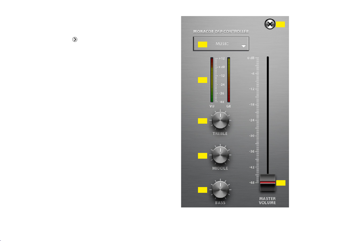
Beim Aufruf einer Gruppe vom Typ „Master Volume“ erscheint
das in Abbildung 15 gezeigte Fenster.
[26]
[27]
[28]
[29]
[30]
[32]
[31]
24
Abb. 15 Gruppensteuerung „Master Volume“
Page 25

Die Anzeige- und Bedienelemente des Gruppensteuerungsfensters
„Master Volume“ haben die folgenden Funktionen:
[26] Schaltfläche zum Schließen des Gruppensteuerungsfensters
[27] Anzeige des aktuellen Presets
Nach dem Klicken auf den Pfeil kann aus einer Liste ein anderes
Preset von den Speicherplätzen 10 – 19 gewählt werden.
[28] Pegelanzeige VU und Anzeige der Verstärkungsminderung GR
(gain reduction) bei Aktivität eines Limiters
[29] Regler TREBLE zur Klangeinstellung der Höhen
Dieser Regler bestimmt den Wert GAIN für das Filter 10 der Eingangskanäle IN-A und IN-B aller Gruppenmitglieder.
[30] Regler MIDDLE zur Klangeinstellung der Mitten
Dieser Regler bestimmt den Wert GAIN für das Filter 9 der Eingangskanäle IN-A und IN-B aller Gruppenmitglieder.
[31] Regler BASS zur Klangeinstellung der Bässe
Dieser Regler bestimmt den Wert GAIN für das Filter 8 der Eingangskanäle IN-A und IN-B aller Gruppenmitglieder.
Die drei Klangregler bestimmen nur den Wert für die Pegelanhebung /-absenkung (GAIN) beim entsprechenden Filter; die übrigen
Parameter (Filterfrequenz, Filtertyp und Güte) bleiben für jedes
Filter individuell einstellbar.
[32] Regler MASTER VOLUME zur Einstellung der Gesamtlautstärke
Der Regler stellt nicht direkt die Lautstärken der einzelnen Gruppenmitglieder ein, sondern wirkt relativ: Steht er in der obersten
Position, gelten die für die Gruppenmitgliedern eingestellten
Werte, wird er heruntergezogen, verringert sich die Lautstärke
bei allen Gruppenmitgliedern proportional. Die Einstellungen in
den einzelnen Lautsprechern werden dadurch nicht verändert.
Wichtig: Damit ein Lautsprecher einer Gruppe vom Typ „Master
Volume“ über die Gruppensteuerung bedient werden kann, muss für
seine aktuelle Zugriffsebene die entsprechende Option freigegeben
sein (☞Kap. 7.4.3):
Master Volume Control = Lautstärkeregelung
Tone Control = Klangregelung
Zudem muss das jeweilige für die Klangregelung vorgesehene Filter
eingeschaltet sein, damit es in der Gruppensteuerung genutzt werden
kann (☞Abbildung 14, Schalter ON [18]).
Deutsch
25
Page 26

7.4 Zugriffsrechte verwalten
7.4.1 Passwörter eingeben
Nach dem Einschalten der Stromversorgung ist generell die Zugriffs-
Deutsch
ebene „User“ ge wählt (☞Kap. 6.1). Um in die höhere Zugriffsebene
„Administrator“ zu gelangen, das entsprechende Passwort über den
Menüpunkt „Hardware Enter Password“ eingeben.
Um im laufenden Betrieb in die „User“-Ebene zurückzukehren,
über denselben Menüpunkt das Passwort für die „User“-Ebene eingeben.
7.4.2 Passwörter ändern
Zum Ändern des Passworts der aktuellen Zugriffsebene den Menüpunkt „Hardware Configure Change Password“ aufrufen. Dabei ist
es erforderlich, zunächst das bisherige Passwort einzugeben, dann das
neue, welches dann noch einmal zur Bestätigung eingegeben werden
muss. Ein geändertes Passwort gut merken!
7.4.3 Zugriffsrechte ändern
Über den Menüzweig „Hardware Configure Global Access Rights“
können die Zugriffsrechte für die niedrigeren Zugriffsebenen festgelegt
werden. Die Tabelle (Abb. 16) zeigt die Möglichkeiten und Voreinstellungen für die einzelnen Ebenen.
7.6 Standby
Um das Gerät in den Bereitschaftsmodus „Standby“ zu versetzen, den
Menüpunkt „Hardware Go to Standby“ aufrufen. Für die Rückkehr
zum normalen Betrieb dann den Menüpunkt „Hardware Exit Standby“ aufrufen (vgl. Kap. 7.2).
7.6.1 Automatischer Standby
Der Lautsprecher kann automatisch in den Bereitschaftsmodus versetzt
werden, nachdem er eine Zeitlang kein Eingangssignal empfangen hat.
Über den Menüpunkt „Hardware Configure Auto Power Down“
die gewünschte Frist in Minuten eingeben.
Zum Deaktivieren dieser Automatik den Wert „0“ eingeben.
7.7 Einschalteinstellungen festlegen
Um festzulegen, mit welchen Einstellungen das Gerät einschalten soll,
den Menüpunkt „Hardware Configure Power On Preset“ aufrufen.
Im Listenfeld des angezeigten Fensters das Preset wählen, das
jedes Mal nach dem Einschalten des Geräts automatisch geladen
werden soll oder die Option „Last Setting“, damit das Gerät nach dem
Einschalten immer die letzten vor dem Ausschalten durchgeführten
Einstellungen be hält.
7.5 Locked State
Um in die unterste Zugriffsebene „Locked State“ zu gelangen, den
Menüpunkt „Hardware Lock Unit“ aufrufen. Eine Meldung wird
angezeigt, die darauf hinweist, dass diese Ebene nur über die Eingabe eines korrekten Passworts einer höheren Ebene wieder verlassen
werden kann. Die Meldung mit OK bestätigen.
26
7.8 Sichern / Zurückladen aller Presets
Zum Sichern aller Presets des Geräts auf dem Computer den Menüpunkt „File Backup Presets“ aufrufen und den Speicherort (Ordner)
wählen.
Zum späteren Zurückladen der gesicherten Presets den Menüpunkt
„File Restore Presets“ aufrufen.
Page 27

7.9 Werkseinstellungen laden
Über den Menüpunkt „File Load Factory Settings“ können Werkseinstellungen geladen werden. Dabei werden zwei Arten von Dateien
unterschieden:
–
Die Factory-Datei enthält Presets mit den dazugehörigen Einstellungen und Zugriffsrechten.
– Die Flash-Image-Datei (*.ffi) enthält zusätzlich die komplette Firm-
7.10 Flash-Image speichern
Zur Datensicherung oder zum Übertragen auf ein anderes Gerät können sämtliche Einstellungen, Presets und die Firmware eines Geräts in
einer Flash-Image-Datei gespeichert werden. Dazu den Menüpunkt
„File Create Flash Image“ aufrufen und einen Dateinamen und Speicherort wählen. Das Laden einer solchen Datei ist über den Menüpunkt
„File Load Factory Settings“ möglich (☞Kap. 7.9).
ware. Das heißt, dass mit der Funktion „Load Factory Settings“ und
dem Laden einer „*.ffi“-Datei gleichzeitig ein Firmware-Update
ausgeführt wird (Hinweise in Kapitel 7.2.5.1 beachten!).
Zugriffsrechte Zugriffsebenen
Access Rights Administrator User Locked State
Load Presets (Menu: Open, Restore Presets)
Save Presets (Menu: Save, Backup Presets)
Load Factory File (Factory Settings)
Create Flash Image
Change Access Rights for User level
Change Access Rights for Locked level
Change Unit Name
Change Unit Configuration (Network, AutoStandby, Startup Preset)
Upgrade the Unit Firmware
Master Volume Control
Tone Control
Access Input Channel
Access Output Channel
✔ = zulässig ☑ / ☐ = zulässig/unzulässig, wählbar
Abb. 16 Mögliche Zugriffsrechte und deren Voreinstellungen
✔ ☑ ☐
✔ ☑ ☐
✔
✔
✔
✔ ☐
✔ ☐ ☐
✔ ☐ ☐
✔ ☐
✔ ☑ ☐
✔ ☑ ☐
✔
Deutsch
27
Page 28

7.11 Netzwerkeinstellungen
Es ist möglich, dem Gerät automatisch eine IP-Adresse zuweisen zu
lassen oder diese manuell einzurichten. Die automatische IP-Adressen-
Deutsch
zuweisung ist voreingestellt.
Um manuell eine IP-Adresse für das Gerät festzulegen:
1) Den Menüpunkt „Hardware Configure Network Settings“ aufrufen.
2) „Configure Network Manually“ anklicken.
3) Die gewünschte IP-Adresse eingeben.
4) Die gewünschte Subnetz-Maske eingeben.
5) Mit Klick auf den „Ok“-Button bestätigen.
Um dem Gerät automatisch eine IP-Adresse zuweisen zu lassen:
1) Den Menüpunkt „Hardware Configure Network Settings“ aufrufen.
2) „Configure Network Automatically“ anklicken.
3) Mit Klick auf den „Ok“-Button bestätigen.
7.12 Gerät mit PIN schützen
Das Gerät kann mit einem PIN-Code gegen einen unerlaubten Zugriff geschützt werden. Dazu den Menüpunkt „Hardware Set PIN“
aufrufen und eine vierstellige Nummer eingeben. Diese muss dann
immer eingegeben werden, wenn zu dem Gerät eine Verbindung
aufgebaut werden soll.
Mit Eingabe der PIN-Nummer „0000“ wird der PIN-Schutz abgeschaltet.
28
Page 29

8 Technische Daten
System: . . . . . . . . . . . . . . . . . . . . . . 2-Wege
Frequenzbereich: . . . . . . . . . . . . . .62 – 20 000 Hz
Lautsprecherbestückung
Tieftöner: . . . . . . . . . . . . . . . . . . ⌀ 13 cm (5¼”)
Hochtöner: . . . . . . . . . . . . . . . . . ⌀ 13 mm (½”)
Kennschalldruck: . . . . . . . . . . . . . . . 89 dB / W/m
max. Nennschalldruck: . . . . . . . . . . 102 dB
Verstärkerleistung (Musikleistung)
bei 12-V-Versorgung: . . . . . . . . . 20 W
bei PoE-Versorgung: . . . . . . . . . . 10 W
Dante-Eingangssignal
Anzahl der Kanäle: . . . . . . . . . . . 2
Auflösung: . . . . . . . . . . . . . . . . . 16 – 32 Bit
Abtastrate: . . . . . . . . . . . . . . . . .44,1 – 96 kHz
Datenschnittstelle
Ethernet: . . . . . . . . . . . . . . . . . . RJ45-Buchse
Signalbearbeitungsmöglichkeiten
Hochpassfilter
Grenzfrequenz: . . . . . . . . . . . . .20 – 500 Hz
Filtertypen: . . . . . . . . . . . . . . . . .Butterworth, Linkwitz-Riley,
Bessel
Filtersteilheit: . . . . . . . . . . . . . . .6 – 24 dB / Oktave
Delay: . . . . . . . . . . . . . . . . . . . . . . . max. 40 ms
Signalbearbeitungsmöglichkeiten je Eingangskanal
Gain: . . . . . . . . . . . . . . . . . . . . . . .−50 dB bis +6 dB
Parametrischer Equalizer
Filteranzahl: . . . . . . . . . . . . . . . . 10
Filtertypen: . . . . . . . . . . . . . . . . .Bell, Notch, High-Shelf,
Low-Shelf, Allpass, Bandpass,
Hochpass, Tiefpass
Filterfrequenz: . . . . . . . . . . . . . . 20 – 20 000 Hz
Filtergüte Q (Typ „Bell“): . . . . . . .0,2 – 25
Verstärkung / Dämpfung: . . . . . . .±12 dB
Pegelbegrenzung (Peak Limiter)
Schwellwert: . . . . . . . . . . . . . . . −48 dBu bis +24 dBu
Rückstellgeschwindigkeit: . . . . . . 10 – 100 dB/s
Allgemein
Zulässige Einsatztemperatur: . . . . . . 0 – 40 °C
Stromversorgung
Power over Ethernet: . . . . . . . . . PoE gemäß IEEE 802.3af-2003
oder über Versorgungsbuchse: . . ⎓12 V/ 2 A
Abmessungen: . . . . . . . . . . . . . . . . 163 × 252 × 165 mm
Gewicht: . . . . . . . . . . . . . . . . . . . . . 1,95 kg
Deutsch
29
Page 30
9 Steuerung über Tabletcomputer/Smartphone
Im „App Store“ des Computerherstellers Apple Inc. sind unter der
Bezeichnung „DSP-CONTROL“ Varianten des DSP-Steuerprogramms
Deutsch
er hältlich.
Auf dem Tabletcomputer funktioniert die DSP-Steuerung ähnlich
wie in den vorangegangenen Kapiteln beschrieben. Die Steuerung mit
dem iPhone beschränkt sich dagegen auf das Anlegen und die Bedienung der Gerätegruppen vom Typ „Master Volume“ (☞Kap. 7.3.4).
Wichtig: Es kann immer nur ein DSP-Steuerprogramm zurzeit aktiv
sein. Eine gleichzeitige DSP-Steuerung von mehreren Stellen aus ist,
auch wenn unterschiedliche Geräte innerhalb eines Netzwerks gesteuert werden sollen, nicht möglich.
Die Geräteübersicht weicht etwas von der in den Kapiteln 7.2 und
7.2.1 beschriebenen Ansicht ab. Die Abbildung 17 zeigt die Geräteübersicht auf einem iPhone, Abbildung 18 die Übersicht auf einem
iPad mit den folgenden Anzeige- und Bedienelementen:
[33] allgemeine Einstellungen
[34] neue Gruppe erstellen
[35] Gruppenname
[36] Gruppe löschen
[37] Gruppe konfigurieren,
z. B. Mitglieder hinzufügen oder entfernen
[38] Fenster zur Gruppensteuerung (☞Kap. 7.3.4) öffnen
[39] Gerätename
[40] Verbindungsstatus des Geräts
[41] Pegelanzeigen des Geräts
[33]
[36][35]
[39]
Abb. 17 Geräteübersicht auf einem iPhone
[37] [38]
[40] [41]
[34]
30
Page 31

[34] [33]
[35] [42]
[43]
[44]
[36] [37] [38]
Deutsch
[46]
[47]
[41]
[39]
Abb. 18 Geräteübersicht auf einem iPad
[42]
Status der Gruppenmitglieder (Gruppenmitglieder / stummge-
[40]
[45]
schaltete Geräte / ausgeschaltete Geräte)
[43] Geräte der Gruppe ein-/ausschalten (Standby)
[44] Gruppe stummschalten
[45] Gerät identifizieren
[46] Gerät stummschalten
[47] Konfigurationsfenster eines Geräts öffnen
(Ansicht MAIN, Abb. 13) Änderungen vorbehalten.
Diese Bedienungsanleitung ist urheberrechtlich für MONACOR ® INTERNATIONAL GmbH & Co. KG geschützt.
Eine Reproduktion für eigene kommerzielle Zwecke – auch auszugsweise – ist untersagt.
31
Page 32

Active Speaker for Dante Networks
These instructions are intended for users with basic knowledge in audio technology and network technology. Please read the instructions
carefully prior to operation and keep them for later reference.
English
Contents
1 Mounting Parts and Connections
2 Important Notes
3 Applications
3.1 Dante . . . . . . . . . . . . . . . . . . . . . . . . . . . . 34
4 Installing and Connecting the Speaker
4.1 Network . . . . . . . . . . . . . . . . . . . . . . . . . . . 35
4.2 Power supply . . . . . . . . . . . . . . . . . . . . . . . . 36
5 Configuration of the Dante Network
5.1 Installing the “Dante Controller” . . . . . . . . . . . . . . 36
5.2 Configuration of the unit with the Dante Controller. . . . . 38
5.3 Routing with the Dante Controller. . . . . . . . . . . . . . 39
6 Operation
6.1 Access levels. . . . . . . . . . . . . . . . . . . . . . . . . 40
6.2 Before operation. . . . . . . . . . . . . . . . . . . . . . . 40
7 The DSP Control Program
7.1 Installing the PC software . . . . . . . . . . . . . . . . . . 41
7.2 Calling up the control program . . . . . . . . . . . . . . . 41
7.2.1 Groups of units . . . . . . . . . . . . . . . . . . . . . . 42
7.2.1.1 Creating a new group . . . . . . . . . . . . . . . . . 42
7.2.1.2 Deleting a group . . . . . . . . . . . . . . . . . . . . 43
7.2.2 Creating a new program password . . . . . . . . . . . . 43
7.2.3 Changing the program password. . . . . . . . . . . . . 43
7.2.4 Demo mode . . . . . . . . . . . . . . . . . . . . . . . 44
. . . . . . . . . . . . . . . . . . . . . . 33
. . . . . . . . . . . . . . . . . . . . . . . . 34
. . . . . . . . . . . . . . . . . . . . . . . . . 40
. . . . . . . . . . . . . 33
. . . . . . . . . 35
. . . . . . . . . . 36
. . . . . . . . . . . . . . . . . 41
7.2.5 Firmware update . . . . . . . . . . . . . . . . . . . . . 44
7.2.5.1 Update via the menu of the configuration window. . . 44
7.2.6 Exiting the program . . . . . . . . . . . . . . . . . . . 45
7.3 Configuring the signal processing . . . . . . . . . . . . . . 46
7.3.1 Signal path . . . . . . . . . . . . . . . . . . . . . . . . 46
7.3.2 View MAIN . . . . . . . . . . . . . . . . . . . . . . . . 48
7.3.3 View IN-A/B . . . . . . . . . . . . . . . . . . . . . . . 50
7.3.4 Group control . . . . . . . . . . . . . . . . . . . . . . 52
7.4 Managing access rights . . . . . . . . . . . . . . . . . . . 54
7.4.1 Entering passwords. . . . . . . . . . . . . . . . . . . . 54
7.4.2 Changing passwords . . . . . . . . . . . . . . . . . . . 54
7.4.3 Changing access rights . . . . . . . . . . . . . . . . . . 54
7.5 Locked State. . . . . . . . . . . . . . . . . . . . . . . . . 54
7.6 Standby . . . . . . . . . . . . . . . . . . . . . . . . . . . 54
7.6.1 Automatic standby . . . . . . . . . . . . . . . . . . . . 54
7.7 Defining the settings to be used after switching on . . . . . 54
7.8 Saving / Loading all presets . . . . . . . . . . . . . . . . . . 54
7.9 Loading factory settings . . . . . . . . . . . . . . . . . . . 55
7.10 Saving a flash image file . . . . . . . . . . . . . . . . . . . 55
7.11 Network settings . . . . . . . . . . . . . . . . . . . . . . 56
7.12 Protecting the unit with a PIN code . . . . . . . . . . . . . 56
8 Specifications
9 Control via Tablet Computer/Smartphone
. . . . . . . . . . . . . . . . . . . . . . . 57
. . . . . . . . 58
32
Page 33

All mounting parts and connections described can be found on page 2.
English
1 Mounting Parts and Connections
1 Speaker
2 Locking screws
3 Metal bracket
4 Plastic support
5
RJ45 jack IN / PoE to connect the speaker to the network (Ethernet)
and to supply the speaker with power via the network (e. g. via
a network switch with PoE power supply). The two LEDs at the
jack indicate connection establishment and data communication.
6 RJ45 jack LINK to route the network connection (e. g. to an addi-
tional WALL-05DT)
The PoE power supply, however, is not routed via this jack. The
two LEDs at the jack indicate connection establishment and data
communication.
7
Power supply jack to connect a 12 V power supply unit as an
alternative to the PoE power supply via the network jack (5)
2 Important Notes
The unit corresponds to all relevant directives of the EU and is therefore
marked with .
The unit is suitable for indoor use only. Protect it against dripping
•
water, splash water and high air humidity. The admissible ambient
temperature range is 0 – 40 °C.
For cleaning only use a dry, soft cloth; never use water or chemicals.
•
No guarantee claims for the unit and no liability for any resulting
•
personal damage or material damage will be accepted if the unit
is used for other purposes than originally intended, if it is not correctly connected or operated, or if it is not repaired in an expert
way. Likewise, no liability will be accepted for any data loss due
to operating errors or a defect or for any consequential damage
caused by this data loss.
If the unit is to be put out of operation definitively, take it
to a local recycling plant for a disposal which is not harmful
to the environment.
33
Page 34

3 Applications
The compact active speaker WALL-05DT is suited for versatile PA
applications, especially for fixed installation (e. g. for background
English
sound and announcements). The speaker is designed as a 2-way
system with a separate amplifier each for the high frequency range and
the low frequency range. The speaker features an Ethernet interface
for connection to a Dante audio network. From this network, audio
signals can be received via one or two channels. At the same time, it
is possible to control the internal signal processor via this interface.
The following functions can be configured in the signal processor via
a computer:
For each of the two input channels separately:
– GAIN
– MUTE
–
parametric equalizer (PEQ) with 10 filters and 8 filter characteristics
– peak limiter
For both input channels together:
–
DELAY, adjustable as a time (ms /s) or a distance (mm / m / mil / inch /feet)
– high pass filter (LOW CUT) with 10 filter characteristics of different
slopes
– LINK facilities of the settings for the two input channels
Various configurations can be saved in WALL-05DT and retrieved as
desired. Remote control via tablet computer or smartphone is possible.
The speaker is supplied with power via the network connection (Power
over Ethernet) or via an additional power supply unit.
3.1 Dante
Dante, an audio network developed by the company Audinate, allows
transmission of up to 512 audio channels at the same time. Dante
(Digital Audio Network Through Ethernet) uses a common Ethernet
standard and is based on the Internet protocol. The transmission
of audio signals is uncompressed and synchronized, with minimum
latency. The advantage over analog audio signal transmission is a
cost-effective connection of components via standard network cables
and low susceptibility to interference, even in case of long transmission
paths. In addition, signal routing between components that have once
been connected can be changed by software at any time. In the Dante
network, units configured as transmitters are used as signal sources. By
means of the program “Dante Virtual Soundcard” from the company
Audinate, computers can also be used as signal sources, e. g. to feed
audio files replayed on the computer to the Dante network.
The speaker WALL-05DT is equipped with two Dante receiving
channels. The signals of these channels can be mixed in the internal
signal processor as desired. The receiving channels are assigned to
any two transmitting channels in the Dante network via the Dante
configuration program “Dante Controller” (☞chapter 5).
Dante™ is a trademark of Audinate Pty Ltd.
34
Page 35

4 Installing and Connecting the Speaker
The speaker is designed for being installed at a wall, but it can also
be set up on its own.
To install the speaker:
1) Remove the plastic support (4) from the metal bracket (3). Then
use two screws to fasten the support to the desired location (e. g.
wall or ceiling).
2) Fasten the metal bracket (3) to the plastic support, using the two
recessed head screws of the bracket. Use the holes in the metal
bracket which are most suitable for the desired speaker alignment.
3) Use the screws (2) to fasten the speaker (1) to the metal bracket.
Align the speaker to the desired sound zone before fastening the
screws.
4.1 Network
To configure the signal processor and to feed in audio signals via a
Dante network, connect the jack IN / PoE (5) to an individual computer, a local computer network or (via a router, for example) to a large
computer network. For correct configuration, knowledge in network
technology is indispensable. The speaker can be supplied with power
via the same connection jack if the jack is connected to a network
element providing “Power over Ethernet” (e. g. PoE switch).
For integration into a Dante network, the speaker must at least
be connected to a Fast Ethernet switch (100 Mbits / s Ethernet).
Even if the same connection jack of WALL-05DT is used for DSP control and for feeding in Dante signals, it is internally considered as two
separate Ethernet interfaces with different IP addresses.
Note: When the IP addresses in the local network are set manually, do not assign
the same address to both interfaces!
The DSP interface of WALL-05DT is preset to automatic reception of
an IP address. If a DHCP server is available in the network connected,
the speaker will receive its address from the server. If an ordinary
Ethernet switch is used to connect the speaker to a computer and the
computer has also been set to automatic reception of an address and
if no DHCP server is available, the units will assign an address in the
range 169.254.0.0 – 169.254.255.255 to each other. This may take a
few minutes (depending on the computer system used). To accelerate
connection without a DHCP server, assign an address in this range to
the computer and set the subnet mask to 255.255.0.0.
The network settings of the DSP interface can easily be changed
via the menu of the control program. In this menu, it is also possible
to assign a fixed IP address to the speaker (☞chapter 7.11).
Note: If the DSP of WALL-05DT is to be configured in large networks by means
of the control program, higher data volumes (e. g. when multiple Dante transmit
channels have been set as multicast flows) may lead to a failure of the control
connection. In this case, it may be necessary to connect a switch ahead of
WALL-05DT which supports “IGMP Snooping” (IGMP = Internet Group Management Protocol). The switch can be configured to reduce the load on WALL-05DT
so that the switch will only route multicast data to WALL-05DT if the speaker
has requested these data.
The Dante interface of the speaker is also preset to automatic address
assignment; configuration via the program “Dante Controller” is
possible. For installation of this program please refer to chapter 5.
The jack LINK (6) can be used for routing the network connection, e. g.
directly to an additional WALL-05DT. The PoE power supply, however,
is not routed via this jack.
English
35
Page 36

4.2 Power supply
Power supply can be made via the network connection (Power over
Ethernet): Connect the jack IN / PoE (5) to a network connection pro-
English
viding PoE (e. g. PoE switch). For a higher output power, connect an
additional power supply. If power supply via PoE is not possible or if
the maximum output power is required, use a DC power connector
with the dimensions 5.5 / 2.1 mm (outside / inside diameter) to connect
a regulated 12 V DC power supply unit with a permanent rating of 2 A
to the jack 12 V ⎓ (7). Observe the correct polarity: inside contact = +.
A suitable power supply unit is, for example, PSS-1230DC from
MONACOR.
5 Configuration of the Dante Network
WALL-05DT is configured as a receiver in the Dante network by means
of the program “Dante Controller”, available as a free download on
the website of the company Audinate. The settings made via the program will be saved in the corresponding transmitters and receivers of
the Dante network so that the program is only required for network
configuration but not for normal operation. The following system
requirements apply to the computer on which the program “Dante
Controller” is to be executed:
Component Minimum requirements
Processor 1 GHz
RAM 512 MBytes
Network
Operating system
Fig. 3 System requirements for “Dante Controller”
Windows is a registered trademark of Microsoft Corporation in the USA and other
countries. Mac OS is a registered trademark of Apple Computer, Inc. in the USA
and other countries.
5.1 Installing the “Dante Controller”
To install the program from the Audinate website:
1) Call up the following Internet address:
https://www.audinate.com/products/software/dante-controller
2) Select the operating system.
3) Click the button with the version of the Dante controller.
Standard Ethernet interface (100 Mbits / s or Gigabit) or
wireless LAN (WiFi) interface
Windows 7 (SP1 or higher), 8.1 or 10
Note: Both UTF-8 and Unicode will be supported, except for host names
and names of units; the DNS standard will not support Unicode for them.
Mac OS X 10.9.5, 10.10.5 or 10.11
Note: Intel architecture only; PPC architecture will not be supported.
36
Page 37

4) Log in or create an account.
5) Download the software.
6) Start the installation program (Dante setup).
Fig. 4 Example: Installation file for Windows
7) Follow the instructions of the installation program.
a)
Read the licence agreement shown in the window “Dante Controller Setup”.
b) Click the check box “I agree…” to accept or click the button
“Close” to cancel the installation.
c) Click the button “Install”.
Fig. 5 Licence agreement of the Dante Controller
d)
Note and accept the warnings of the operating system that
follow.
e)
Click the button “Close” to close the window “Dante Controller
Setup” with the message “Setup Successful” or alternatively,
click the button “Launch” to start the Dante Controller software.
Fig. 6 Dante Controller – “Setup Successful”
English
37
Page 38

5.2 Configuration of the unit with the Dante Controller
1) Start the Dante Controller.
2) Wait for the desired Dante transmitter and WALL-05DT to appear
English
in the matrix (under “Dante Receivers”).
Note: If WALL-05DT or the Dante transmitter fails to appear, the reason may
be that the corresponding unit has not been switched on, that the unit is in a
different subnet or that the unit is not able to synchronize with the other Dante
units. However, if one of the two last-mentioned reasons applies, the Dante
unit should at least appear under the tab “Device Info” or “Clock Status” in
the network view. A fast solution of the problem may be to switch off the unit
or to disconnect the connection to the switch. For further information please
refer to the user manual of the Dante Controller from Audinate.
3)
In the menu bar of the Dante Controller, select “Device/Device
View” or use the shortcut Ctrl+D. The Device View window will
open.
4)
Select “WALL-05DT” in the bar of the drop-down menu appearing
beneath the menu bar.
5) The third bar can be used to indicate information on the unit and
to make settings. Select the tab “Device Config” (refer to fig. 7).
6) Adjust the “Sample Rate” to the desired Dante transmitter or set
a different common sample rate for both units, if required.
7) In the field “Rename Device”, the name used for the unit in the
Dante network can be changed (e. g. to a specific name referring
to the place of installation). Click “Apply” to confirm the change.
Fig. 7 Device View of WALL-05DT
8) Use the tab “Network Config” to change the network settings for
the Dante interface of WALL-05DT, if required.
38
Page 39

5.3 Routing with the Dante Controller
To assign the input signals and output signals of the corresponding
units:
1)
Under “Routing” in the window “Network View”, click ⊞ to open
the channels of the desired Dante transmitter under “Dante Transmitters” and the channels of WALL-05DT under “Receivers”.
2)
Navigate from the Dante transmit channel to the line of the desired
Dante receive channel of WALL-05DT and click the field.
3) Wait for the field to show a green circle with a white check mark
(refer to fig. 8).
4) Repeat the last two steps for the second Dante receive channel of
WALL-05DT, if required.
English
Fig. 8 Audio routing from the audio source “VirtualSoundcard”
to the receiver “WALL-05DT”
An English user guide for the Dante Controller is available for download on the Audinate website:
https://www.audinate.com/resources/technical-documentation
39
Page 40

6 Operation
The speaker does not feature any control elements. Its signal processor
(DSP) is exclusively operated by remote control via the network from
English
a computer (☞chapter 7). In addition, operation via tablet computer
and restricted control of speaker groups via smartphone is possible
(☞chapter 9).
In any case, please note that the range of available functions
depends on the access rights of the user. These rights are defined
in access levels (☞chapter 6.1) to be configured according to your
requirements.
6.1 Access levels
If it is not possible to execute all operating steps described in the
manual, this may be due to restricted access rights.
For configuration, three access levels with different rights are
available. The levels “Administrator” and “User” are accessed via
different passwords.
The following table shows the access levels in descending order and
the corresponding passwords:
Access level Password *
Administrator mega_adm
User monacor
Locked State —
Fig. 9 Default passwords
* The passwords are factory-set and can be changed by the user at the corre-
sponding access level. Make sure to remember the password after changing it!
The passwords are saved in the speaker. When the speaker is switched
on, it is always at the level “User”. To change the level during operation, enter the corresponding password via the menu item “Hardware
Enter Password” of the control program (☞chapter 7.4.1) or call
up the “Locked State” via the menu item “Hardware Lock Unit”
(☞chapter 7.5).
At the access level “Administrator”, the control options of lower
levels can be restricted (☞chapter 7.4.3).
6.2 Before operation
If you do not know the start settings of the speaker after switching on
the power supply, set the audio sources at the Dante network to a low
volume. This will prevent undesired high volumes after switching on.
After switching on the power supply, the speaker will load the previous
settings or a specific preset defined for this purpose (☞chapter 7.7).
40
Page 41

7 The DSP Control Program
7.1 Installing the PC software
The required software is available for download on our website under
“Service / Downloads”.
https://www.monacor.com/en-gb/monacorinternational/service/
These instructions refer to the version 3.8.22 of the PC software. To
install the DSP control program, a computer with the operating system
Windows XP with Service Pack 2 or later or Mac OS X, version 10.5.8
or later and an Ethernet interface is required. The screen resolution
should be at least 1024 × 768 pixels.
– To install the PC software on a Windows system, start the suitable
installation program “MONACOR_DSP_Controller […] .msi” and
follow the instructions of the installation program.
– On a computer with Mac OS X system, start the program “MONA-
COR DSP Controller.app”.
7.2 Calling up the control program
1) Call up the control program “DSP Controller” on the computer.
2)
If a password has been assigned to the program (☞chapter 7.2.2),
a window will appear requesting to enter the password. Enter the
password.
If the password is not correct, the message “Invalid password”
will appear. In this case, confirm the message and enter the correct
password.
The overview window (fig. 10) will appear, listing all units connected.
The line “All units” at the top will indicate the number of units which
are currently “on line” in brackets, i. e. units which are actively connected to the computer. Beneath this line, there are lines with information and functions for each unit.
Fig. 10 Overview window
Note: The program “DSP Controller” is not only used to control speakers of the
type WALL-05DT but also other units from MONACOR with integrated signal
processor. Therefore, the list also contains DSM-48LAN.
English
41
Page 42

Description of functions:
1. Button to mute the unit
When the unit is muted, the button is red. To unmute, click the
English
button again. Clicking the button in the line “All Units” will
mute any units connected.
2. Button to identify a unit
When this button is clicked, the button and all LEDs on the unit
will flash for a few seconds.
3. Icon for the operating status of the unit
green = operation
red = standby
grey = connection interrupted
Click the icon to switch between operating mode and standby
mode. When the unit is switched on and a new connection is
being established, an additional line “Startup…” with the icon
will temporarily appear at the end of the list.
4. The two vertical bars are basic level indicators for the input and
the output of a unit.
5. Indication of unit name
The preset name can be changed here or in the configuration
menu (☞chapter 7.3.2) in order to distinguish between identical
units. It is advisable to use the name used in the Dante network.
6. Indication of the hardware address (MAC address) of the interface
of the unit; this address will always clearly identify a unit
7. Indication of the IP address of a unit
When the connection is interrupted, “Offline” is indicated here.
8. Button to call up the configuration window (fig. 13) for a unit
which is “on line”
In the line “All Units”, click the button to hide the list of units
or click to show the list.
7.2.1 Groups of units
Multiple units can be combined in groups for controlling them together.
They may, for example, all be muted. The settings of the group
define which parameters of the group will apply to all members of
this group. All actions of a group require the necessary access rights
for the group members.
There are three types of groups:
“Carbon Copy”: All settings (except the parameters defined under
“Exceptions”) in the configuration window of the
group or a group member will apply to all other
group members.
“Advanced”: Only the settings of the parameters defined under
“Setup Links” will apply to the group members.
“Master Volume”: Only essential settings such as total volume or
basic sound adjustment can be made for all group
members (☞ chapters 7.3.4).
7.2.1.1 Creating a new group
1)
To create a new group, call up the menu item “Tools New Group”.
2) A window is displayed: Enter the desired group name in the field
“Enter the name of the new group”.
A line for the group will be added to the list (line “Group:…”,
fig. 11).
☞
42
Page 43

3) The button is used to create or change a group. It is possible
to add or remove members (Members: Select …) and to change
group names, group types and link characteristics. A group can
also be temporarily disabled or enabled. In addition, it is possible
to enter text to describe the group.
The line “Group: …” shows the current number of group
members (units) after the group name.
4) The button at the end of the line “Group: …” is used to call up
the configuration window of the group. When the configuration
window of the group is already open, this button can be used to
show a list of all group members and the button to hide the
list (double-click, if necessary). While the configuration windows
of the group types “Carbon Copy” and “Advanced” are similar
to those for individual units (☞chapters 7.3.2 and 7.3.3), groups
of the type “Master Volume” have a specific control window
(☞chapter7.3.4).
7.2.1.2 Deleting a group
To delete a group, click the button in the corresponding line
(☞fig.11). A confirmation box will appear, asking you to confirm
the deletion process. If there are units assigned to this group at this
moment, another confirmation box will appear.
Fig. 11 Overview window with groups
7.2.2 Creating a new program password
To create a password protection for starting the program:
1) Call up the menu item “Tools Set Software Password”.
2) Enter the desired password in the field “Enter New Password:” of
the window displayed.
3)
Another window will appear: To confirm, enter the password once
again in the field “Confirm New Password:” and make sure to
remember it!
7.2.3 Changing the program password
To change the password for starting the program:
1) Call up the menu item “Tools Change Software Password”.
2) Enter the current password in the field “Enter Old Password:” of
the window displayed.
3) Another window will appear: Enter the new password in the field
“Enter New Password:”.
English
43
Page 44

4)
Another window will appear: To confirm, enter the password once
again in the field “Confirm New Password:” and make sure to
remember it!
English
7.2.4 Demo mode
If no unit is connected to the computer, it is possible to create a virtual
unit for demonstration purposes. For this purpose, call up the menu
item “Tools Enter Demo Mode”.
A list will appear, showing various virtual units with the addition
“DEMO…”. Just like for real units, the button is used to call up
the configuration menu (☞fig. 13).
To delete the virtual units from the list, call up the menu item
“Tools Leave Demo Mode”.
7.2.5 Firmware update
The control program and the unit must be equipped with matching
firmware versions to ensure smooth communication. If the control
program is a later version, it is possible to update the firmware (operating system) of the units via the control program. After an update,
all settings saved on the units will be lost. To keep the settings, save
them on the computer before starting the update (☞chapters 7.8
and 7.10).
Note: Firmware updates are made at your own risk. After an update, the func-
tions of the unit may differ from the functions described in the instruction
manual.
CAUTION: Switch off the signal sources or reduce their output levels
to prevent unexpected high volumes after resetting.
To update the firmware of a unit, call up the menu item “Tools Enable
Update”. An icon will appear after the units in the list. When the
icon is grey, an update is not possible (e. g. because the firmware of
the unit has already been updated or because the access rights do not
permit an update). When the icon is orange, an update is possible:
1) Click the button in the line of the desired unit.
2) A message will appear warning the user not to switch off the unit
during the multi-step update process or not to disconnect the
connection. If the update fails, start it once again.
Start the update with [OK] or cancel it with [Cancel].
3)
When the update has been successful, another message will appear.
Confirm this message as well.
To hide the update icons in the list, call up the menu item “Tools
Disable Update”.
Note: A reset to the factory settings will also affect the network settings and
the passwords of the unit, i. e. for the time being, it may be impossible
to access the unit from the computer (compare note in chapter 7.2.5.1).
7.2.5.1 Update via the menu of the configuration window
It is also possible to update the firmware via the menu of the configuration window (Hardware Firmware Update) if the unit is at the
access level “Administrator” or if it is at the access level “User” and
the corresponding access right “Upgrade the unit firmware” has been
granted to the “User” level (☞chapter 7.4.3).
44
Page 45

At the administrator level, manual selection of the firmware is also
possible. To open the File Explorer, go to “File Load Factory Settings”
in the menu of the configuration window. A flash image file (extension “.ffi”) does not only contain the presets and the corresponding
settings and access options; it also contains the complete firmware.
Note for loading a flash image file (*.ffi): When a flash image is loaded, a
firmware update will be made and then a factory file will be loaded.
A firmware update will reset the unit to automatic IP address assignment
(“Network Settings” ☞chapter 7.11). Therefore, the computer may no longer
be able to access a unit that was previously set to a fixed IP address. As a result
of this disconnection, the flash image file may not be loaded completely.
Important: Before loading a flash image file, make sure that an IP address has
automatically been assigned both to the PC network interface and to the unit.
7.2.6 Exiting the program
To exit the program, call up the menu item “File Quit” or close the
program window.
English
45
Page 46

7.3 Configuring the signal processing
ATTENTION
English
To configure the speaker, click the button in the list next to the
speaker (☞ figs. 10, 11).
The configuration window (fig. 13) with the view MAIN for the
unit selected will appear. The colour field on the left next to UNIT
CONNECTION [2] will indicate the connection status of the unit. When
the colour field is green, a data connection has been established.
When the colour field is red, the connection has been interrupted and
it is not possible to change the setting. If the user tries to change the
setting, a corresponding message will appear.
In case of connection, any setting changed on the screen will
be immediately transferred to the unit. It is possible to save the settings as presets on the computer and in the unit (☞ chapter 7.3.2).
Furthermore, it can be defined if a specific preset or the previous
settings will be loaded when the unit is switched on (☞ chapter 7.7).
The buttons at the top [1] can be used to switch to the views of
the input channels IN-A and IN-B (fig. 14). However, this will only be
possible at the access level “Administrator”. To return to the main
view, click the button MAIN.
Combined with the control program, the signal processor is an effective tool for making slightest but also
major changes to the transmission properties of the
speaker.
Therefore, any change of parameter should be
carefully considered and be made with the required
expertise. In the worst case, extreme changes of the
settings may damage the speaker.
7.3.1 Signal path
Figure 12 shows a block diagram of the path a signal takes through
the speaker system. The two input signals coming from the Dante
network pass the following stages:
➾ input amplifier (GAIN)
➾ 10-band equalizer (PEQ)
➾ level limiter (LIMITER)
➾ summing mixer
➾ signal delay (DELAY)
➾ high pass filter (LOW CUT)
The subsequent signal processing (crossover network, limiter to protect the speaker from overload, etc.) has been specially matched to
WALL-05DT in the factory and cannot be accessed by the user.
The parameters of the blocks shown in the grey box can be set in
the views MAIN, IN-A and IN-B. Some parameters may be accessed
from various views.
Note: The setup options depend on the access rights of the current access level
(☞chapter 6.1). To be able to make all settings, select the access level
“Administrator” when the control program is called up for the first time.
From this level, the access rights for the other access levels can be defined
according to the group of intended users of the unit (☞chapter 7.4).
46
Page 47

MUTE
IN A
PEQ 1 – 10
1
Dante
2
LINK
MUTE
IN B
PEQ 1 – 10
Fig. 12 Block diagram of the signal path
out
in
LIMITERGAIN
LOW CUTDELAY
out
in
LIMITERGAIN
HF
PEQ 1 – 10
CROSSOVER
LF
PEQ 1 – 10
out
LIMITERDELAYGAIN
out
LIMITERDELAYGAIN
D
A
in
D
A
in
English
47
Page 48

7.3.2 View MAIN (fig. 13)
[1] Buttons to switch over the view (change of view only possible at
English
the access level “Administrator”)
[2] UNIT CONNECTION – connection status
green = connected
red = not connected
[3] Name of unit; unit can be renamed
[4] PC PRESET
“SAVE” the current settings as presets on the computer (like
menu item “File Save”) and “LOAD” the presets from the com-
puter (like menu item “File Open”)
[5] SPEAKER PRESET
“SAVE” the current settings as presets in the speaker and “LOAD”
the presets from the speaker
Select the storage location in the list field and enter a name in
the upper field.
Note: To allow selection of a preset from the group control, save the preset
to one of the storage locations 10 – 19.
[6]
INPUT CONTROL for setting the gain (volume) for the inputs, level
indicators next to the control, input /display fields as a numeric
input facility beneath the control
[7] Level indicator MASTER LEVEL for the outputs LF (bass speaker)
and HF (tweeter)
[8] LINK switch (for controlling the two input channels together)
Channel IN-B will adopt the settings of channel IN-A.
[9] MUTE switch for muting the corresponding input
[10] List field to select the unit of measurement for the DELAY value
[11]: time or distance (for automatic calculation of the delay)
[11]
Input /display field DELAY for setting the signal delay of the input
signals (e. g. to compensate differences in sound delay due to
different distances of individual speakers to the listening position)
Alternatively, use the sliding control to set the signal delay.
[12] List field to select the filter type for the high pass filter LOW CUT
with the following options:
Indication Filter type Slope
But 6dB Butterworth 6 dB/octave
Bes 6dB Bessel 6 dB/octave
But 12dB Butterworth 12 dB/octave
Bes 12dB Bessel 12 dB/octave
L-R 12dB Linkwitz-Riley 12 dB/octave
But 18dB Butterworth 18 dB/octave
Bes 18dB Bessel 18 dB/octave
But 24dB Butterworth 24 dB/octave
Bes 24dB Bessel 24 dB/octave
L-R 24dB Linkwitz-Riley 24 dB/octave
[13]
High pass filter LOW CUT: Input /display field for the cut-off
frequency (enter values in Hz, “Off” < 20Hz)
Alternatively, use the sliding control to set the frequency.
48
Page 49

[3]
[4]
[1]
English
[2]
[6] [7]
[5]
Fig. 13 Configuration window in the view MAIN
[8]
[9]
[11]
[12][10]
[13]
49
Page 50

7.3.3 View IN-A/B (fig. 14)
[14] Buttons to switch over the view
[15]
English
GAIN control to set the gain (volume) for the corresponding
input, level indicators next to the control, input /display field as
a numeric input facility beneath the control (same effect as [6])
[16] Curve representation of the amplitude frequency response
Each of the 10 parametric filters has its own reference point
(small square with the filter number) and a frequency curve in its
own colour. The resulting frequency response of all active filters
is shown as a white curve.
Some of the filter parameters can be set graphically. For this purpose, use the mouse to shift the corresponding reference point:
– horizontal shift to change the frequency
– vertical shift to change the gain
–
horizontal shift with the right mouse button to change the
quality factor/ bandwidth
– double-click the reference point to switch a filter on /off
Control functions on the left of the diagram:
Enlarged view ➾ full screen display;
use to reduce the view
Save curves as image file (PNG)
Fine adjustment on/off
Show/ hide the values of all active filters
[17]
MUTE switch to mute the corresponding input (same effect as [9]
[18] Switch ON to activate /deactivate a filter
[19] List field TYPE to select the filter type: Bell, Notch, Allpass, High
Shelf, Low Shelf, Band Pass, High Pass, Low Pass
[20]
Input / display field FREQ for the filter frequency (enter values in Hz)
[21]
Input / display field Q / BW for the quality factor / bandwidth (to
switch over, click Q or BW)
[22] Input / display field GAIN to boost /attenuate the level of the filter
Note: The adjustability of the parameters GAIN and Q/BW depends on the
filter characteristic TYPE selected.
[23] LIMITER: sliding control THRESHOLD with input / display field for
the limit value; when the signal level exceeds this value, the
gain will be reduced, i. e. the signal level has been limited to this
specific value
Note: To deactivate the limiter, set the maximum limit value (24 dBu).
[24] LIMITER: sliding control RELEASE with input /display field for the
release speed of the gain after the input signal level has fallen
below the limit value
[25] LINK switch “A+B” to link the two input channels
(same effect as [8])
50
Page 51

[15]
[14]
English
[16]
[23]
[24]
[17]
Fig. 14 View IN-A
[18] [19]
[20] [21] [22]
[25]
51
Page 52

7.3.4 Group control
As described in chapter 7.2.1, it is possible to create groups of units
to be controlled together. Use the button behind the group in the
English
overview (fig. 11) to call up the configuration window.
For controlling groups of units of the type “Carbon Copy” and
“Advanced”, the same configuration windows like for configuring the
individual units are used (☞chapters 7.3.2 and 7.3.3). It depends on
the settings of the individual group which parameters can be changed
in the configuration windows for the group (☞chapter 7.2.1).
When a group of the type “Master Volume” is called up, the
window shown in figure 15 will appear.
[26]
[27]
[28]
[29]
[30]
[32]
[31]
52
Fig. 15 Group control “Master Volume”
Page 53

The indicator and control elements of the group control window
“Master Volume” have the following functions:
[26] Button to close the group control window
[27] Indication of current preset
After clicking the arrow, another preset can be selected from a
list of the storage locations 10 – 19.
[28] Level indication VU and indication of gain reduction GR when
the limiter is active
[29] Control TREBLE to adjust the high frequencies
This control will define the GAIN value for filter 10 of the input
channels IN-A and IN-B of all group members.
[30] Control MIDDLE to adjust the midrange frequencies
This control will define the GAIN value for filter 9 of the input
channels IN-A and IN-B of all group members.
[31] Control BASS to adjust the low frequencies
This control will define the GAIN value for filter 8 of the input
channels IN-A and IN-B of all group members.
The three equalizer controls only define the value for boosting/
attenuating the level (GAIN) for the corresponding filter; the
other parameters (filter frequency, filter type and quality factor)
are individually adjustable for each filter.
[32] Control MASTER VOLUME to set the total volume
This control will not directly set the volumes of the individual
group members but affects them in a relative way: When the
control is in the upper position, the values adjusted for the group
members will apply. Sliding down the control will proportionally
reduce the volume for all group members. The settings of the
individual speakers will not be affected.
Important: To be able to operate a speaker from a group of the type
“Master Volume” via the group control, the corresponding option for
its current access level must be enabled (☞chapter 7.4.3):
Master Volume Control
Tone Control
In addition, switch on the corresponding filter designed for tone
control so that it can be used in group control (☞figure 14, switch
ON [18]).
English
53
Page 54

7.4 Managing access rights
7.4.1 Entering passwords
English
When the power supply is switched on, the access level “User” will
always be selected (☞chapter 6.1). To go to the higher access level
“Administrator”, enter the corresponding password via the menu
item “Hardware Enter Password”.
To return to the “User” level during operation, enter the password
for the “User” level via the same menu item.
7.4.2 Changing passwords
To change the password of the current access level, call up the menu
item “Hardware Configure Change Password”. Enter the current
password first, then enter the new password and enter the new password again to confirm. Always make sure to remember the new
password!
7.4.3 Changing access rights
The access rights for the lower access levels can be defined via the
menu branch “Hardware Configure Global Access Rights”. The
table (fig. 16) shows the options and presets for the individual levels.
7.5 Locked State
To go to the lowest access level “Locked State”, call up the menu
item “Hardware Lock Unit”. A message will appear pointing out
that you have to enter the correct password of a higher level before
you are able to exit the present level. Confirm this message with OK.
7.6 Standby
To set the unit to “Standby”, call up the menu item “Hardware
Go to Standby”. To return to normal operation, call up the menu
item “Hardware Exit Standby” (compare chapter 7.2).
7.6.1 Automatic standby
When the speaker has not received any input signal for a while, it can
automatically be set to standby. Enter the desired time in minutes via
the menu item “Hardware Configure Auto Power Down”.
To deactivate this automatic feature, enter the value “0”.
7.7 Defining the settings to be used after switching on
To define the settings to be used when the unit is switched on, call up
the menu item “Hardware Configure Power On Preset”.
In the list field of the window displayed, select the preset to be
loaded automatically whenever the unit is switched on or select the
option “Last Setting” so that the unit will always start with the settings
of its previous operation before it was switched off.
7.8 Saving / Loading all presets
To save all presets of the unit to the computer, call up the menu item
“File Backup Presets” and select the storage location (folder).
To load presets that have been saved, call up the menu item
“File Restore Presets”.
54
Page 55

7.9 Loading factory settings
Use the menu item “File Load Factory Settings” to load factory
settings. There are two different types of files:
–
The factory file contains presets with the corresponding settings
and access rights.
–
The flash image file (*.ffi) also contains the complete firmware,
i. e. when the function “Load Factory Settings” is used and a “*.ffi”
file is loaded, a firmware update will be made at the same time.
(Please observe the notes in chapter 7.2.5.1.)
7.10 Saving a flash image file
For backup or for transferring settings to another unit, all settings,
presets and the firmware of a unit can be saved to a flash image file:
Call up the menu item “File Create Flash Image” and select a file
name and a storage location. Such a file can be loaded via the menu
item “File Load Factory Settings” (☞ chapter 7.9).
English
Access Rights
Load Presets (Menu: Open, Restore Presets)
Save Presets (Menu: Save, Backup Presets)
Load Factory File (Factory Settings)
Create Flash Image
Change Access Rights for User level
Change Access Rights for Locked level
Change Unit Name
Change Unit Configuration (Network, AutoStandby, Startup Preset)
Upgrade the Unit Firmware
Master Volume Control
Tone Control
Access Input Channel
Access Output Channel
✔ = allowed ☑ / ☐ = allowed/not allowed, selectable
Fig. 16 Available access rights and their presets
Administrator User Locked State
✔ ☑ ☐
✔ ☑ ☐
✔
✔
✔
✔ ☐
✔ ☐ ☐
✔ ☐ ☐
✔ ☐
✔ ☑ ☐
✔ ☑ ☐
✔
Access Levels
55
Page 56

7.11 Network settings
An IP address can either be automatically assigned to the unit or it can
be configured manually. The automatic IP address assignment is preset.
English
To manually set an IP address for the unit:
1)
Call up the menu item “Hardware Configure Network Settings”.
2) Click “Configure Network Manually”.
3) Enter the desired IP address.
4) Enter the desired subnet mask.
5) Click “OK” to confirm.
To automatically assign an IP address to the unit:
1) Call up the menu item “Hardware Configure Network Settings”.
2) Click “Configure Network Automatically”.
3) Click “OK” to confirm.
7.12 Protecting the unit with a PIN code
A PIN code can be used to protect the unit against unauthorized
access: Call up the menu item “Hardware Set PIN” and enter a
four-digit number. This number must always be entered to make a
connection to the unit.
When the PIN code “0000” is entered, the PIN protection will be
deactivated.
56
Page 57

8 Specifications
System: . . . . . . . . . . . . . . . . . . . . . . 2-way system
Frequency range: . . . . . . . . . . . . . .62 – 20 000 Hz
Speaker configuration
Bass speaker: . . . . . . . . . . . . . . . ⌀ 13 cm (5 ¼”)
Tweeter: . . . . . . . . . . . . . . . . . . . ⌀ 13 mm (½”)
Sensitivity: . . . . . . . . . . . . . . . . . . . . 89 dB / W/ m
max. SPL: . . . . . . . . . . . . . . . . . . . . 102 dB
Amplifier power (music power)
with 12 V power supply: . . . . . . . 20 W
with PoE power supply: . . . . . . .10 W
Dante input signal
Number of channels: . . . . . . . . .2
Resolution: . . . . . . . . . . . . . . . . . 16 – 32 bits
Sampling rate: . . . . . . . . . . . . . . 44.1 – 96 kHz
Data interface
Ethernet: . . . . . . . . . . . . . . . . . . RJ45 jack
Signal processing options
High pass filter
Cut-off frequency: . . . . . . . . . . . 20 – 500 Hz
Filter types: . . . . . . . . . . . . . . . . . Butterworth, Linkwitz-Riley,
Bessel
Slope: . . . . . . . . . . . . . . . . . . . . . 6 – 24 dB /octave
Delay: . . . . . . . . . . . . . . . . . . . . . . . 40 ms max.
Signal processing options for each input channel
Gain: . . . . . . . . . . . . . . . . . . . . . . .−50 dB to +6 dB
Parametric equalizer
Number of filters: . . . . . . . . . . . . 10
Filter types: . . . . . . . . . . . . . . . . . Bell, Notch, High Shelf,
Low Shelf, Allpass, Bandpass,
High Pass, Low Pass
Filter frequency: . . . . . . . . . . . . . 20 – 20 000 Hz
Quality factor Q (type “Bell”): . . . 0.2 – 25
Gain/attenuation: . . . . . . . . . . . .± 12 dB
Peak Limiter
Limit value: . . . . . . . . . . . . . . . . . –48 dBu to +24 dBu
Release speed: . . . . . . . . . . . . . . 10 – 100 dB / s
General
Admissible ambient temperature: . . 0 – 40 °C
Power supply
Power over Ethernet: . . . . . . . . . PoE in accordance with
IEEE 802 3af-2003
or via power supply jack: . . . . . .⎓12 V/ 2 A
Dimensions: . . . . . . . . . . . . . . . . . . 163 × 252 × 165 mm
Weight: . . . . . . . . . . . . . . . . . . . . .1.95 kg
English
57
Page 58

9 Control via Tablet Computer/Smartphone
In the “App Store” of Apple Inc., variants of the DSP control program
are available under the name “DSP-CONTROL”.
English
The DSP control on a tablet computer is similar to that described
in the previous chapters. Control via iPhone, however, is limited to
creation and operation of groups of speakers of the type “Master
Volume” (☞chapter 7.3.4).
Important: Only a single DSP program can be active at a time.
Simultaneous DSP control from multiple locations is not possible, even
if different units are to be controlled within a network.
The overview of units slightly differs from the view described in chapters 7.2 and 7.2.1. Figure 17 shows the overview of units on an iPhone;
figure 18 shows the overview on an iPad with the following display
and control elements:
[33] General settings
[34] Create a new group
[35] Group name
[36] Delete a group
[37] Configure a group
e. g. add or remove members
[38] Open a window for group control (☞chapter 7.3.4)
[39] Name of the unit
[40] Connection status of the unit
[41] Level indications of the unit
[39]
[33]
[36][35]
[37] [38]
[40] [41]
[34]
58
Fig. 17 Overview of units on an iPhone
Page 59

[34] [33]
[35] [42]
[43]
[44]
[36] [37] [38]
English
[46]
[47]
[41]
[39]
Fig. 18 Overview of units on an iPad
[45]
[40]
[42] Status of group members (members /muted /off)
[43] Switch members of the group on /off (standby)
[44] Mute a group
[45] Identify a unit
[46] Mute a unit
[47] Open the configuration window of a unit
(view MAIN, fig. 13) Subject to technical modification.
All rights reserved by MONACOR ® INTERNATIONAL GmbH & Co. KG.
No part of this instruction manual may be reproduced in any form or by any means for any commercial use.
59
Page 60

Enceinte active pour réseaux Dante
Cette notice s’adresse aux utilisateurs avec des connaissances de base en technologie audio et technologie réseau. Veuillez lire la présente
notice avec attention avant le fonctionnement et conservez-la pour pouvoir vous y reporter ultérieurement.
Français
Table des matières
1 Composants de montage et branchements
2 Conseils importants d’utilisation
3 Possibilités d’utilisation
3.1 Dante . . . . . . . . . . . . . . . . . . . . . . . . . . . . 62
4 Montage et branchement de l’enceinte
4.1 Réseau. . . . . . . . . . . . . . . . . . . . . . . . . . . . 63
4.2 Alimentation. . . . . . . . . . . . . . . . . . . . . . . . . 64
5 Créer un réseau Dante
5.1 Installer le programme «Dante Controller» . . . . . . . . . 64
5.2 Configurer des appareils avec le Dante Controller . . . . . . 66
5.3 Routage avec le Dante Controller . . . . . . . . . . . . . . 67
6 Utilisation
6.1 Niveaux d’accès . . . . . . . . . . . . . . . . . . . . . . . 68
6.2 Utilisation . . . . . . . . . . . . . . . . . . . . . . . . . . 68
7 Le programme de commande DSP
7.1 Installation du logiciel PC . . . . . . . . . . . . . . . . . . 69
7.2 Appeler le programme de commande . . . . . . . . . . . . 69
7.2.1 Groupes d’appareils . . . . . . . . . . . . . . . . . . . 70
7.2.1.1 Créer un nouveau groupe . . . . . . . . . . . . . . . 70
7.2.1.2 Effacer un groupe . . . . . . . . . . . . . . . . . . . 71
7.2.2 Créer un mot de passe du programme . . . . . . . . . . 71
7.2.3 Modifier un mot de passe du programme . . . . . . . . 71
7.2.4 Mode Démo . . . . . . . . . . . . . . . . . . . . . . . 72
. . . . . . . . . . . . . . . . . . . . . . . . . 68
. . . . . . . . . . . . . . . . . . 62
. . . . . . . . . . . . . . . . . . . 64
. . . . . . . . . . . . . 61
. . . . . . . . . . . . 69
. . . . . . . 61
. . . . . . . . . 63
7.2.5 Mise à jour du firmware . . . . . . . . . . . . . . . . . 72
7.2.5.1 Mise à jour via le menu de la fenêtre de configuration . 72
7.2.6 Quitter le programme . . . . . . . . . . . . . . . . . . 73
7.3 Configuration du traitement du signal. . . . . . . . . . . . 74
7.3.1 Voie de signal. . . . . . . . . . . . . . . . . . . . . . . 74
7.3.2 Visualisation MAIN . . . . . . . . . . . . . . . . . . . . 76
7.3.3 Visualisation IN-A / B. . . . . . . . . . . . . . . . . . . . 78
7.3.4 Gérer des groupes . . . . . . . . . . . . . . . . . . . . 80
7.4 Gérer des droits d’accès . . . . . . . . . . . . . . . . . . . 82
7.4.1 Saisir le mot de passe . . . . . . . . . . . . . . . . . . . 82
7.4.2 Modifier le mot de passe . . . . . . . . . . . . . . . . . 82
7.4.3 Modifier les droits d’accès . . . . . . . . . . . . . . . . 82
7.5 Locked State – Verrouillage . . . . . . . . . . . . . . . . . 82
7.6 Standby . . . . . . . . . . . . . . . . . . . . . . . . . . . 82
7.6.1 Standby automatique. . . . . . . . . . . . . . . . . . . 82
7.7 Définir les réglages d’allumage . . . . . . . . . . . . . . . 82
7.8 Sauvegarder / Recharger tous les presets . . . . . . . . . . . 82
7.9 Charger les réglages d’usine. . . . . . . . . . . . . . . . . 83
7.10 Mémoriser une image Flash . . . . . . . . . . . . . . . . . 83
7.11 Réglages réseau . . . . . . . . . . . . . . . . . . . . . . . 84
7.12 Protéger l’appareil avec un code PIN. . . . . . . . . . . . . 84
8 Caractéristiques techniques
9 Gestion via une tablette / smartphone
. . . . . . . . . . . . . . . . 85
. . . . . . . . . . 86
60
Page 61

Vous trouverez sur la page 2 les composants de montage et les branchements.
1 Composants de montage et branchements
1 Enceinte
2 Vis de fixation
3 Etrier métallique
4 Support plastique
5 Prise RJ45 IN / PoE pour relier l’enceinte à un réseau (Ethernet) et
pour alimenter l’enceinte via le réseau (par exemple via un Switch
réseau avec alimentation PoE).
Les deux LEDs sur la prise indiquent l’établissement de la connexion
et le trafic de données.
6 Prise RJ45 LINK pour diriger la connexion réseau par exemple vers
une autre WALL-05DT
L’alimentation PoE n’est pas dirigée via cette prise. Les deux LEDs
sur la prise indiquent l’établissement de la connexion et le trafic
de données.
7 Prise alimentation pour brancher un bloc secteur 12 V à la place
d’une alimentation PoE via la connexion réseau (5)
2 Conseils importants d’utilisation
L’appareil répond à toutes les directives nécessaires de l’Union européenne et porte donc le symbole .
L’appareil n’est conçu que pour une utilisation en intérieur. Pro-
•
tégez-le des éclaboussures, de tout type de projections d’eau et
d’une humidité élevée de l’air. La plage de température ambiante
admissible est de 0 – 40 °C.
Pour le nettoyage, utilisez uniquement un chiffon sec et doux, en
•
aucun cas de produits chimiques ou d’eau.
Nous déclinons toute responsabilité en cas de dommages matériels
•
ou corporels résultants si l’appareil est utilisé dans un but autre que
celui pour lequel il a été conçu, s’il n’est pas correctement branché
ou utilisé ou s’il n’est pas réparé par une personne habilitée ; en
outre, la garantie deviendrait caduque. De même, notre responsabilité ne saurait être engagée en cas de pertes de données causées par
une mauvaise utilisation ou un défaut, ni pour leurs conséquences.
Lorsque l’appareil est définitivement retiré du service, vous
devez le déposer dans une usine de recyclage de proximité
pour contribuer à son élimination non polluante.
Français
CARTONS ET EMBALLAGE PAPIER À TRIER
61
Page 62

3 Possibilités d’utilisation
L’enceinte active compacte WALL-05DT est adaptée pour différentes
applications de sonorisation, en particulier pour une installation fixe
Français
(par exemple pour une sonorisation d’ambiance et des annonces).
C’est un système deux voies avec respectivement un amplificateur
pour la plage des aigus et des graves. L’enceinte dispose d’une interface Ethernet pour une connexion à un réseau audio Dante à partir
duquel les signaux audio peuvent être reçus via un ou deux canaux.
Simultanément via cette interface, il est possible de gérer le processeur interne de signal. Via un ordinateur, vous pouvez configurer les
fonctions suivantes dans le processeur de signal.
Pour chacun des deux canaux d’entrée séparément :
– amplification (GAIN)
– coupure du son (MUTE)
–
égaliseur paramétrique (PEQ) avec 10 filtres et 8 caractéristiques
de filtre
– limiteur Peak
Pour les deux canaux d’entrée ensemble :
–
temporisation du signal (DELAY), réglable en durée (ms /s) ou
distance (mm / m / mil / pouce / pied)
–
filtre passe-haut (LOW CUT) avec 10 caractéristiques de filtre de
pente différente
–
possibilité de couplage des réglages des deux canaux d’entrée (LINK)
Il est possible de mémoriser différentes configurations dans la
WALL-05DT et les appeler selon les besoins. Une commande à distance
via une tablette ou un Smartphone est possible.
L’alimentation de l’enceinte peut se faire soit via la connexion réseau
(Power over Ethernet) soit via un bloc secteur supplémentaire.
3.1 Dante
Dante est un réseau audio développé par la société Audinate avec
lequel il est possible de transmettre simultanément jusqu’à 512 canaux audio. Dante (Digital Audio Network Through Ethernet) utilise
un standard Ethernet répandu et se base sur le protocole Internet. La
transmission des signaux audio se fait de manière non compressée,
synchronisée et avec une latence minimale. L’avantage par rapport
à une transmission analogique de signal audio est la connexion des
composants via un câble réseau standard à un prix faible et une faible
sensibilité aux interférences même pour de longues distances. De plus,
la transmission du signal entre les composants reliés entre eux peut
à tout moment être modifiée via le logiciel. Dans le réseau Dante, les
appareils installés comme émetteurs (Transmitter) servent de source
de signal. Via le programme «Dante Virtual Soundcard» de la société
Audinate, on peut également utiliser des ordinateurs comme sources
de signal, pour par exemple insérer dans le réseau Dante, des fichiers
audio lus sur l’ordinateur.
L’enceinte WALL-05DT est dotée de deux canaux de réception
Dante dont les signaux peuvent être mixés selon les besoins dans
le processeur interne de signal. L’attribution des canaux de réception à deux canaux émetteurs souhaités dans le réseau Dante se
fait via le programme de configuration Dante «Dante Controller»
(☞chapitre5).
Dante™ est une marque déposée de Audinate Pty Ltd.
62
Page 63

4 Montage et branchement de l’enceinte
L’enceinte est prévue pour un montage mural, mais elle peut également être posée directement.
Pour monter l’enceinte :
1) Retirez le support plastique (4) de l’étrier métallique (3) et vissez
avec deux vis à l’endroit de montage souhaité (par exemple mur
ou plafond).
2)
Fixez l’étrier métallique (3) avec ses deux vis cruciformes sur le
support plastique. Choisissez sur l’étrier métallique les trous les
mieux adaptés en fonction de l’orientation souhaitée de l’enceinte.
3) Fixez l’enceinte (1) avec les vis (2) sur l’étrier métallique. Avant de
visser complètement, orientez l’enceinte vers la zone de sonorisation.
4.1 Réseau
Pour la configuration du processeur de signal et pour insérer les
signaux audio via un réseau Dante, reliez la prise IN PoE (5) avec un
ordinateur individuel, un réseau local d’ordinateurs ou, par exemple,
via un routeur à des réseaux d’ordinateurs plus vastes. Pour une
installation correcte, des connaissances en technologie réseau sont
indispensables. L’alimentation de l’enceinte se fait via la même prise
de branchement si elle est reliée à un élément du réseau mettant à
disposition le «Power over Ethernet» (par exemple Switch PoE).
Pour une intégration dans un réseau Dante, l’enceinte doit au
moins être reliée à un Switch Fast Ethernet (Ethernet 100 Mbits /s).
Même lorsque la gestion DSP et l’intégration des signaux Dante se fait
via la même prise de branchement de la WALL-05DT, il s’agit en interne
de deux interfaces Ethernet distinctes avec des adresses IP différentes.
Remarque : Dans le cas d’une définition manuelle des adresses IP dans le réseau
local, ces deux interfaces ne doivent pas avoir la même adresse !
L’interface DSP de la WALL-05DT est préréglée sur l’obtention automatique d’une adresse IP. Si dans le réseau connecté, il y a un serveur
DHCP, l’enceinte reçoit son adresse de lui. Si l’enceinte est reliée à
un ordinateur via un simple Switch Ethernet, qui de même est réglé
sur l’obtention automatique d’une adresse et s’il n’y a pas de serveur
DHCP, les appareils s’attribuent de manière réciproque, une adresse
dans la plage 169.254.0.0 – 169.254.255.255. Dans certains cas (selon
le système d’ordinateur utilisé), cela peut durer quelques minutes.
Pour accélérer la connexion sans serveur DHCP, définissez une adresse
dans cette plage pour l’ordinateur et réglez le masque sous-réseau
sur 255.255.0.0.
Les réglages réseau de l’interface DSP peuvent être facilement
modifiés via le menu du programme de commande. Il est également
possible d’attribuer une adresse IP fixe à l’enceinte (☞chapitre 7.11).
Remarque : Si le DSP de la WALL-05DT doit être configuré avec le programme
de commande dans des réseaux plus importants, il peut y avoir des perturbations
dans la liaison de commande dans le cas d’un flux élevé de données (par exemple
si plusieurs canaux Dante Transmit sont réglés comme flows Multicast). Dans
ce cas, il peut être nécessaire de brancher avant la WALL-05DT, un Switch qui
accepte le «IGMP Snooping» (IGMP = Internet Group Management Protocol).
Le Switch peut être configuré de telle sorte qu’il décharge la WALL-05DT dans
la mesure où il dirige uniquement les données Multicast vers la WALL-05DT qui
ont été demandées par l’enceinte.
Français
63
Page 64

L’interface Dante de l’enceinte est également préréglée pour une
attribution automatique de l’adresse et peut être configurée via le
programme «Dante Controller». L’installation de ce programme est
décrite dans le chapitre 5.
Français
La prise LINK (6) peut être utilisée pour diriger la connexion réseau,
par exemple directement vers une autre WALL-05DT. L’alimentation
PoE n’est cependant pas dirigée vers cette prise.
4.2 Alimentation
L’alimentation peut se faire via la connexion réseau (Power over
Ethernet). Pour ce faire, reliez la prise IN / PoE (5) à la connexion réseau
délivrant le PoE (par exemple Switch PoE). Une puissance supérieure de
sortie peut être obtenue via une alimentation supplémentaire reliée.
Si aucune alimentation par PoE n’est possible ou si la puissance maximale de sortie est nécessaire, reliez un bloc secteur avec une tension
continue stabilisée de 12 V et une charge continue de 2 A via une fiche
alimentation 5,5 / 2,1 mm (diamètre extérieur/diamètre intérieur) à la
prise 12 V ⎓ (7). Veillez à respecter la polarité : contact interne = +.
Pour l’alimentation, le bloc secteur PSS-1230DC de MONACOR, par
exemple, est bien adapté.
5 Créer un réseau Dante
L’installation de la WALL-05DT comme récepteur dans le réseau Dante
se fait via le programme «Dante Controller» disponible gratuitement
via le site internet de la société Audinate. Les réglages effectués via
le programme sont mémorisés dans les émetteurs et récepteurs participants du réseau Dante de telle sorte que le programme ne soit
nécessaire que pour la configuration du réseau et pas pendant le
fonctionnement normal. Pour l’ordinateur, sur lequel le programme
«Dante Controller» doit fonctionner, il faut suivre les configurations
système suivantes :
Composant Configuration minimale
Processeur 1 GHz
Mémoire de travail 512 MBytes
Réseau
Système d’exploitation
Schéma 3 Configuration du système pour «Dante Controller»
Windows est une marque déposée de Microsoft Corporation aux Etats-Unis et
dans les autres pays. Mac OS est une marque déposée de Apple Computer, Inc.
aux Etats-Unis et dans les autres pays.
5.1 Installer le programme «Dante Controller»
Pour installer le programme depuis le site internet de Audinate :
1) Allez à l’adresse internet suivante :
https://www.audinate.com/products/software/dante-controller
2) Sélectionnez le système d’exploitation.
Interface Ethernet standard (100 Mbit /s ou Gigabit) ou
interface LAN sans fil (Wi-Fi)
Windows 7 (SP1 ou supérieur), 8.1 ou 10
Remarque : UTF-8 et Unicode supportés, sauf pour nom hôte et nom
appareil ; le standard DNS n’accepte pas Unicode pour ceux-ci.
Mac OS X 10.9.5, 10.10.5 ou 10.11
Remarque : uniquement architecture Intel, architecture PCC non acceptée.
64
Page 65

3) Cliquez sur le bouton avec la version du contrôleur Dante.
4) Connectez-vous ou créez un compte.
5) Téléchargez le logiciel.
6) Démarrez le programme d’installation (Dante-Setup) :
Schéma 4 Exemple : fichier d’installation pour Windows
7) Suivez les consignes du programme d’installation :
a)
Lisez le texte de licence s’affichant dans la fenêtre «Dante
Controller Setup».
b) En cochant la case «I agree...» vous acceptez les indications de
la licence, ou bien arrêtez l’installation avec le bouton «Close».
c) Cliquez sur le bouton «Install».
e)
Fermez la fenêtre «Dante Controller Setup» avec le message
«Setup Successful» en cliquant sur le bouton «Close» ou
démarrez le logiciel Dante Controller en cliquant sur le bouton
«Launch».
Schéma 6 Dante Controller – «Setup Successful»
Français
Schéma 5 Validation de la licence de Dante Controlle
d)
Lisez les avertissements suivants de système d’exploitation et
validez-les.
65
Page 66

5.2 Configurer des appareils avec le Dante Controller
1) Démarrez le Dante Controller.
2)
Attendez jusqu’à ce que l’émetteur Dante souhaité et la WALL-05DT
Français
(sous «Dante Receivers») s’affichent dans la matrice.
Remarque : Si le WALL-05DT ou l’émetteur Dante n’apparaît pas, la raison
peut être : l’appareil n’est pas allumé, se trouve dans un autre sous-réseau
ou ne peut pas être synchronisé avec les autres appareils Dante. Pour une
des deux raisons citées en dernier, il faut que l’appareil Dante soit présenté
au moins dans la visualisation Network sous l’onglet «Device Info» ou «Clock
Status». Un arrêt de l’appareil ou l’interruption de la liaison vers le Switch
pourrait être une solution rapide au problème. Vous trouverez des informations
complémentaires dans la notice du Dante Controller de Audinate.
3) Dans la barre de menu du Dante Controller, sélectionnez «Device /
Device View» ou appuyez sur la combinaison de touches Ctrl+D.
La fenêtre Device View s’affiche.
4)
Dans la barre s’affichant sous la barre de menu, dans le menu
déroulant, sélectionnez la «WALL-05DT».
5)
Dans la troisième barre, différentes informations sur l’appareil
s’affichent et on peut effectuer des réglages. Sélectionnez l’onglet
«Device Config» (voir schéma 7).
6)
Si besoin, adaptez le «Sample Rate» à l’émetteur Dante souhaité ou
définissez un autre Sample Rate (taux d’échantillonnage) commun
pour les deux appareils.
7)
Dans le champ «Rename Device», il est possible de modifier le
nom utilisé pour l’appareil dans le réseau Dante (par exemple un
nom unique en rapport avec le lieu d’installation). Confirmez toute
modification avec «Apply».
Schéma 7 Device-View de la WALL-05DT
8) Via l’onglet «Network Config», vous pouvez si besoin modifier les
réglages réseau pour l’interface Dante de la WALL-05DT.
66
Page 67

5.3 Routage avec le Dante Controller
Pour attribuer les signaux d’entrée et de sortie des appareils utilisés :
1)
Dans la fenêtre «Network View», sous «Routing», ouvrez les
canaux de l’émetteur Dante souhaité sous «Dante Transmitters» et
les canaux de la WALL-05DT sous «Dante Receivers», en cliquant
sur le symbole ⊞.
2)
Naviguez à partir du canal Dante Transmit jusqu’à la ligne du canal
Dante Receive souhaité de la WALL-05DT et cliquez sur le champ.
3) Attendez jusqu’à ce que le champ affiche un cercle vert coché en
blanc (voir schéma 8).
4)
Effectuez les deux derniers points pour le second canal Dante
Receive de la WALL-05DT, si besoin.
Français
Schéma 8 Routing audio de la source audio «VirtualSoundcard»
vers le récepteur «WALL-05DT»
Sur le site de Audinate, il est possible de télécharger un manuel d’utilisation en anglais du Dante Controller :
https://www.audinate.com/resources/technical-documentation
67
Page 68

6 Utilisation
L’enceinte ne dispose d’aucun élément de commande. Son processeur
de signal (DSP) est géré à distance exclusivement via le réseau depuis
Français
un ordinateur (☞chapitre 7). En plus, une utilisation via une tablette
ou une gestion limitée de groupes d’enceintes par un Smartphone est
possible (☞chapitre 9).
Dans tout cas, il faut prendre en compte que la plage de fonctionnalités à disposition dépend des droits d’accès de l’utilisateur.
Ces droits sont définis dans les niveaux d’accès (☞chapitre 6.1) qui
peuvent être configurés selon les besoins.
6.1 Niveaux d’accès
Si tous les processus d’utilisation décrits dans la notice ne peuvent
pas être effectués, il est possible que les droits d’accès limités en
soient la cause.
Pour la configuration de l’appareil, trois niveaux d’accès avec droits
différents sont disponibles. L’accès aux niveaux «Administrator» et
«User» est accessible via différents mots de passe.
Le tableau suivant indique les niveaux d’accès en ordre décroissant et
les mots de passe correspondants.
Niveau d’accès Mot de passe *
Administrator mega_adm
User monacor
Locked State —
Schéma 9 Mots de passe préréglés
* Ces mots de passe sont préréglés en usine et peuvent être modifiés par l’utili-
sateur dans le niveau d’accès correspondant. Pensez à bien noter les mots de
passe modifiés !
Les mots de passe sont mémorisés dans l’enceinte. Après l’allumage,
elle est en général au niveau «User». Pour changer de niveau pendant le fonctionnement, saisissez le mot de passe correspondant via
le point de menu «Hardware Enter Password» (☞chapitre 7.4.1)
ou appelez «Locked State» via le point de menu «Hardware Lock
Unit» (☞chapitre 7.5).
Dans le niveau d’accès «Administrator», les possibilités d’utilisa-
tion des niveaux inférieurs peuvent être limitées (☞chapitre 7.4.3).
6.2 Utilisation
Si vous ne savez pas avec quels réglages l’enceinte démarre une fois
l’alimentation activée, réglez tout d’abord les sources audio sur le
réseau Dante sur un volume faible. Ainsi, vous éviterez un volume
trop fort à l’allumage.
Après l’allumage de l’alimentation, les réglages du dernier fonctionnement sont chargés ou un preset défini pour l’allumage (☞chapitre7.7).
68
Page 69

7 Le programme de commande DSP
7.1 Installation du logiciel PC
Vous pouvez télécharger le logiciel nécessaire sur notre site dans la
rubrique «Service / Downloads» :
https://www.monacor.com/fr-fr/monacorinternational/service/
Cette notice fait référence à la version 3.8.22 du logiciel PC. Configuration du système pour l’installation du programme de commande
DSP : ordinateur avec système d’exploitation Windows XP avec Service
Pack2 ou version Windows supérieure ou Mac OS X à partir de 10.5.8
et interface Ethernet. La résolution d’écran doit être de 1024 × 768
points au moins.
–
Pour l’installation du logiciel PC sur un système Windows, démarrez le programme d’installation correspondant «MONACOR_
DSP_Controller […] .msi» et suivez les instructions du programme
d’installation.
–
Sur un ordinateur avec un système Mac OS X, démarrez le pro
gramme «MONACORDSPController.app».
7.2 Appeler le programme de commande
1)
Sur l’ordinateur, appelez le programme de commande
«DSP Controller».
2)
Si un mot de passe a été créé pour le programme (☞chapitre7.2.2),
une fenêtre s’ouvre pour saisir le mot de passe. Tapez-le.
En cas d’erreur lors de la saisie du mot de passe, le message
«Invalid password!» s’affiche. Dans ce cas, validez le message et
retapez le mot de passe.
La fenêtre de visualisation (schéma 10) s’affiche. Une liste de tous
les appareils reliée s’affiche. Dans la ligne supérieure «All Units», le
nombre d’appareils «online», c’est-à-dire en liaison active avec l’ordinateur, est indiqué entre parenthèses. En dessous, il y a une ligne pour
chaque appareil avec différentes informations et fonctions.
-
Schéma 10 Fenêtre de visualisation
Remarque : Avec le programme «DSP Controller», on peut gérer non seulement
des enceintes WALL-05DT mais aussi d’autres appareils de MONACOR avec
processeur de signal intégré. C’est pourquoi, un DSM-48LAN est également
présenté sur le schéma.
Français
69
Page 70

Description des fonctions :
1. Bouton pour couper le son de l’appareil
Lorsque le son est coupé, le bouton est rouge. Pour réactiver le
Français
son, cliquez à nouveau sur le bouton. En cliquant sur le bouton
dans la ligne «All Units», le son est simultanément coupé pour
tous les appareils reliés.
2. Bouton pour identifier un appareil
En cliquant le bouton, il clignote pendant quelques secondes et
avec lui toutes les LEDs sur l’appareil.
3. Symbole pour l’état de fonctionnement de l’appareil
vert = fonctionnement
rouge = mode veille (Standby)
gris = connexion interrompue
En cliquant sur le symbole, vous pouvez commuter entre fonctionnement et veille. Si lors de l’allumage d’un appareil, une nouvelle
connexion est établie, une ligne supplémentaire «Startup...» avec
le symbole s’affiche à la fin de la liste de manière temporaire.
4. Les deux barres verticales représentent un affichage simple de
niveau pour l’entrée et la sortie d’un appareil.
5. Affichage du nom de l’appareil
Le nom préréglé peut être modifié pour distinguer des appareils
identiques, soit ici soit dans la fenêtre de configuration (☞chapitre7.3.2). Il convient d’utiliser le même nom que dans le réseau
Dante.
6. Affichage de l’adresse Hardware (adresse MAC) de l’interface de
l’appareil via laquelle un appareil peut toujours être identifié de
manière unique
7. Affichage de l’adresse IP d’un appareil
En cas de connexion interrompue, «Offline» est visible à la place.
8. Bouton pour appeler la fenêtre de configuration (schéma 13)
pour un appareil qui est «online».
Dans la ligne «All Units» on peut masquer la liste des appareils via
la zone ou l’afficher via .
7.2.1 Groupes d’appareils
Il est possible de regrouper plusieurs appareils dans des groupes pour
une gestion commune. Vous pouvez par exemple couper le son de
tous les appareils. Les paramètres des appareils groupés qui doivent
être gérés ensemble peuvent être définis via les réglages du groupe.
Toutes les actions d’un groupe présupposent que les membres du
groupe sont chargés avec les droits d’accès nécessaires.
Il y a trois types de groupes :
«Carbon Copy» : Tous les réglages dans la fenêtre de configuration
du groupe ou d’un membre du groupe sont repris
par tous les membres du groupe, à l’exception des
paramètres définis au point «Exceptions».
«Advanced» : Seuls les réglages des paramètres définis sous
«Setup Links» sont repris par les membres du
groupe.
«Master Volume» : Seuls les réglages de base, comme le volume
général et le réglage simple de tonalité, peuvent
être effectués ensemble (☞chapitre 7.3.4).
7.2.1.1 Créer un nouveau groupe
1) Pour créer un nouveau groupe, appelez le point de menu «Tools
New Group».
70
Page 71

2) Dans la fenêtre qui s’affiche, saisissez le nom souhaité du groupe
dans le champ «Enter the name of the new group».
Dans la liste, une ligne supplémentaire pour le groupe s’affiche
(ligne «Group : ...», ☞ schéma 11).
3)
Via le bouton , vous pouvez créer un groupe ou le modifier. Il est
possible d’ajouter des membres, d’en retirer (Members : Select ...) et
de modifier le nom du groupe, le type de groupe et les propriétés
de couplage. Un groupe peut, en plus, être désactivé (disabled) de
manière temporaire ou réactivé (enabled). Il est également possible
de saisir un texte descriptif pour le groupe.
Dans la ligne «Group : ...», le nombre actuel de membres du
groupe (units) s’affiche après le nom du groupe.
4) Via le bouton , à la fin de la ligne «Group : ...», on peut appeler la fenêtre de configuration du groupe. Si la fenêtre est déjà
ouverte, vous pouvez, via ce bouton, afficher une liste de tous les
membres du groupe ou, via , masquer la liste (par double clic,
si besoin). Alors que les fenêtres de configuration des types de
groupe «Carbon Copy» et «Advanced» sont identiques à celles des
appareils individuels (☞ chapitres 7.3.2 et 7.3.3), les groupes de
type «Master Volume» ont une fenêtre spécifique pour la gestion
(☞chapitre 7.3.4).
7.2.1.2 Effacer un groupe
Pour effacer un groupe, cliquez dans la ligne correspondante sur le
bouton (☞ schéma 11). Une demande de confirmation pour valider
le processus d’effacement s’affiche. Si des appareils sont attribués à ce
moment-là au groupe, une autre demande de confirmation s’affiche.
Français
Schéma 11 Fenêtre de visualisation avec un groupe
7.2.2 Créer un mot de passe du programme
Pour créer un mot de passe pour démarrer le programme :
1) Appelez le point de menu «Tools Set Software Password».
2) Dans la fenêtre qui s’ouvre, saisissez le mot de passe voulu dans le
champ «Enter New Password».
3) Dans la nouvelle fenêtre, saisissez à nouveau le nouveau mot de
passe pour confirmation dans le champ «Confirm New Password:»
et notez-le pour vous en souvenir.
7.2.3 Modifier un mot de passe du programme
Pour modifier le mot de passe pour démarrer le programme :
1) Appelez le point de menu «Tools Change Software Password».
2) Dans la fenêtre qui s’ouvre, saisissez l’ancien mot de passe dans le
champ «Enter Old Password».
3) Dans la nouvelle fenêtre, saisissez le nouveau mot de passe dans
le champ «Enter New Password».
71
Page 72

4)
Enfin, dans la nouvelle fenêtre, saisissez à nouveau le nouveau
mot de passe pour confirmation dans le champ «Confirm New
Password:» et notez-le pour vous en souvenir.
Français
7.2.4 Mode Démo
Même si aucun appareil n’est relié à l’ordinateur, il est possible de
créer un appareil virtuel pour des démonstrations. Appelez le point
de menu «Tools Enter Demo Mode».
Dans la liste, différents appareils virtuels s’affichent avec la description supplémentaire «DEMO...». Comme pour les appareils réels,
vous pouvez appeler la fenêtre de configuration via le bouton
(☞schéma 13).
Pour retirer les appareils virtuels de la liste, appelez le point de
menu «Tools Leave Demo Mode».
7.2.5 Mise à jour du firmware
Pour une communication sans problème entre le programme de gestion et un appareil, ils doivent avoir, tous deux, des versions correspondantes. Si le programme de gestion a une nouvelle version, on
peut actualiser le firmware (système d’exploitation) des appareils via
le programme de commande. Tous les réglages mémorisés dans les
appareils sont alors perdus ! Si les réglages doivent être conservés,
il faut les sauvegarder sur l’ordinateur avant l’actualisation (☞chapitres7.8 et 7.10).
Remarque : Une actualisation du firmware se fait à vos propres risques. Après
une mise à jour, le fonctionnement de l’appareil peut différer de la
description dans la notice.
ATTENTION : Eteignez les sources de signal ou diminuez-en le niveau
de sortie pour éviter tout volume fort non attendu après la réinitialisation des réglages.
Pour faire la mise à jour du firmware d’un appareil, appelez le point
de menu «Tools Enable Update». Derrière les appareils dans la liste,
le symbole s’affiche. Si le symbole est gris, aucune mise à jour n’est
possible (par exemple parce que le firmware de l’appareil est déjà à
jour ou parce que les droits d’accès sont insuffisants). Si le symbole
est orange, la mise à jour peut se faire :
1) Dans la ligne de l’appareil souhaité, cliquez sur le bouton .
2)
Un conseil s’affiche que pendant l’actualisation en plusieurs étapes,
l’appareil ne doit pas être éteint et que la connexion ne doit pas être
interrompue. En cas d’erreur de l’actualisation, recommencez-la.
Démarrez l’actualisation en cliquant sur [OK] ou arrêtez en cliquant
sur [Cancel].
3) Une fois l’actualisation réussie, un message s’affiche. Confirmez
de la même manière.
Pour ne pas afficher les symboles de mise à jour dans la liste, appelez
le point de menu «Tools Disable Update».
Remarque : Lors de la réinitialisation des réglages sur les réglages usine, les
réglages réseau et les mots de passe de l’appareil sont impactés,
c’est-à-dire qu’il est possible que vous n’ayez plus accès à l’appareil
depuis l’ordinateur pour le moment (voir conseil chapitre 7.2.5.1).
7.2.5.1 Mise à jour via le menu de la fenêtre de configuration
Une mise à jour du firmware est également possible via le menu de
la fenêtre de configuration (Harware Firmware Update) si l’appareil
est au niveau «Administrator» ou s’il est au niveau «User», et ce
niveau est réglé sur les droits d’accès nécessaires «Upgrade the unit
firmware» (☞chapitre 7.4.3).
Au niveau Administrator, vous pouvez sélectionner manuellement un
firmware au choix. Dans «File Load Factory Settings», via le menu de
72
Page 73

la fenêtre de configuration, l’explorateur de fichiers s’ouvre. Un fichier
image Flash (extension «.ffi») contient, en plus des presets, des réglages correspondants et des possibilités d’accès, le firmware complet.
Conseils pour charger un fichier image Flash (*.ffi) : Le chargement d’une
image flash entraîne une mise à jour du firmware et le chargement d’un fichier
Factory.
Dans la mesure où une mise à jour du firmware réinitialise l’appareil sur une
attribution automatique d’adresse IP («Network Settings», ☞chapitre 7.11), il
est possible que vous n’ayez plus accès depuis l’ordinateur à un appareil sur lequel
une adresse IP fixe était auparavant réglée. Cela conduit à ce que le chargement
de l’image Flash ne puisse pas se poursuivre à cause d’une connexion manquante.
Important : Avant de charger une image Flash, faites attention qu’une adresse
IP est automatiquement attribuée à l’interface réseau du PC et à l’appareil.
7.2.6 Quitter le programme
Pour quitter le programme, appelez le point de menu «File Quit» ou
fermez la fenêtre du programme.
Français
73
Page 74

7.3 Configuration du traitement du signal
ATTENTION
Français
Pour configurer l’enceinte, cliquez, dans la liste pour l’enceinte sur le
bouton (☞ schémas 10, 11).
La fenêtre de configuration (schéma 13) avec la visualisation principale (MAIN) est affichée pour l’appareil sélectionné. Sur le côté
gauche, dans le champ de couleur à côté de UNIT CONNECTION [2],
l’état de connexion de l’appareil s’affiche. Si le champ est vert, il y a
une connexion de données. Si le champ est rouge, la connexion est
interrompue, la modification d’un réglage n’est alors pas possible. En
cas de tentative, un message correspondant s’affiche.
Les réglages modifiés sur l’écran sont tout de suite transmis à
l’appareil lorsque la connexion est établie. Les réglages peuvent être
mémorisés sur l’ordinateur et dans l’appareil (☞chapitre 7.3.2)
comme preset. On peut également définir si, lorsque vous allumez
l’appareil, un preset donné doit être chargé ou si le dernier état avant
l’arrêt prévaut (☞chapitre 7.7).
Via les boutons dans la rangée supérieure [1], vous pouvez
commuter sur les visualisations des canaux d’entrée IN-A et IN-B
(schéma14). Cela n’est possible qu’au niveau d’accès «Administrator».
Via le bouton MAIN, vous revenez à la visualisation principale.
Le processeur de signal est, en liaison avec le programme de gestion, un outil efficace avec lequel des
modifications très précises mais aussi majeures sur les
propriétés de transmission de l’enceinte sont possibles.
Toute modification des paramètres ne doit donc être
faite qu’en toute connaissance de cause. Des modifications extrêmes des réglages peuvent entraîner, dans le
pire des cas, des dommages sur l’enceinte.
7.3.1 Voie de signal
Le schéma 12 présente sous forme de schéma-bloc, la voie de signal
au travers de l’enceinte. Les deux signaux d’entrée venant du réseau
Dante passent à travers les stations suivantes :
➾ amplificateur d’entrée (GAIN)
➾ réglage de tonalité 10 bandes (PEQ)
➾ limitation de niveau (LIMITER)
➾ amplificateur de mixage (sommateur)
➾ temporisation signal (DELAY)
➾ filtre passe-haut (LOW CUT)
Le traitement de signal résultant (filtre de fréquence, limiteur pour
protéger les enceintes de toute surcharge ...) est spécifiquement défini
en usine sur la WALL-05DT et n’est pas accessible à l’utilisateur.
Les paramètres dans les blocs affichés dans la case grise, peuvent être
réglés dans les visualisations MAIN, IN-A, IN-B. Pour certains, l’accès
à partir de plusieurs visualisations est possible.
Remarque : Les possibilités de réglage dépendent des droits d’accès du niveau
d’accès actuel (☞chapitre 6.1). Pour pouvoir effectuer tous les
réglages, il faut, lorsque vous appelez la première fois le programme
de commande, passer au niveau d’accès «Administrator». A partir
de là, il est possible de définir les droits d’accès pour les autres
niveaux d’accès en fonction du cercle de personnes prévu pour
utiliser l’appareil (☞chapitre 7.4).
74
Page 75

MUTE
IN A
PEQ 1 – 10
1
Dante
2
LINK
MUTE
IN B
PEQ 1 – 10
Schéma 12 Schéma-bloc de la voie de signal
out
in
LIMITERGAIN
LOW CUTDELAY
out
in
LIMITERGAIN
HF
PEQ 1 – 10
CROSSOVER
LF
PEQ 1 – 10
out
LIMITERDELAYGAIN
out
LIMITERDELAYGAIN
D
A
in
D
A
in
Français
75
Page 76

7.3.2 Visualisation MAIN (schéma 13)
[1] Boutons pour commuter la visualisation (changement possible
uniquement au niveau d’accès «Administrator»)
Français
[2] UNIT CONNECTION – Etat de connexion
vert = connecté
rouge = non connecté
[3] Nom de l’appareil ; peut être modifié en l’écrasant
[4] PC PRESET
Mémorisation «SAVE» des réglages actuels comme preset sur
l’ordinateur (comme le point de menu «File Save») et charge-
ment «LOAD» depuis l’ordinateur (comme le point de menu
«File Open»)
[5] SPEAKER PRESET
Mémorisation «SAVE» des réglages actuels comme preset dans
l’appareil et chargement «LOAD» d’un preset mémorisé dans
l’appareil
Sélectionnez l’emplacement de mémorisation dans le champ et
saisissez le nom dans le champ supérieur.
Remarque : Pour qu’un preset soit également sélectionnable via la gestion
[6]
Réglage INPUT CONTROL pour le réglage d’amplification (volume)
de groupe, il doit être mémorisés dans un des emplacements
10 à 19.
pour les entrées, à côté VU-mètres, en dessous champs de saisie /
affichage comme possibilité de saisie numérique
[7]
VU-mètres MASTER LEVEL pour les sorties LF (grave) et
HF (tweeter)
[8]
Interrupteur LINK pour coupler (c’est-à-dire pour une gestion
commune) les deux canaux d’entrée
Le canal IN-B reprend les réglages du canal IN-A.
[9]
Interrupteur MUTE pour couper le son de l’entrée correspondante
[10] Champ pour sélectionner l’unité pour la valeur de DELAY [11]:
durée ou distance (pour un calcul automatique de la propagation
du son).
[11]
Champ de saisie / affichage DELAY pour le réglage d’une temporisation de signal des signaux d’entrée (par exemple pour
compenser des différences de durée causées par des distances
différentes des haute-parleurs individuels par rapport à la position
d’écoute) La temporisation de signal peut à la place être réglée
avec le potentiomètre à glissière.
[12]
Champ pour sélectionner le type de filtre pour le filtre passe-haut
LOW CUT avec les options suivantes :
Affichage Type filtre Pente
But 6dB Butterworth 6 dB/octave
Bes 6dB Bessel 6 dB/octave
But 12dB Butterworth 12 dB/octave
Bes 12dB Bessel 12 dB/octave
L-R 12dB Linkwitz-Riley 12 dB/octave
But 18dB Butterworth 18 dB/octave
Bes 18dB Bessel 18 dB/octave
But 24dB Butterworth 24 dB/octave
Bes 24dB Bessel 24 dB/octave
L-R 24dB Linkwitz-Riley 24 dB/octave
[13] Filtre passe-haut LOW CUT : champ de saisie /affichage pour la
fréquence limite (saisissez les valeurs en Hz, «Off» < 20Hz)
La fréquence peut à la place être réglée avec le potentiomètre
à glissières.
76
Page 77

[1]
[2]
[3]
[4]
[5]
Schéma 13 Fenêtre de configuration dans la visualisation MAIN
[6] [7]
[11]
[8]
[9]
Français
[12][10]
[13]
77
Page 78

7.3.3 Visualisation IN-A / B (schéma 14)
[14] Boutons pour commuter la visualisation
[15] Réglage GAIN pour régler l’amplification (volume) pour l’entrée
Français
correspondante, à côté VU-mètre, en dessous champ de saisie /
affichage comme possibilité de saisie numérique (même action
que [6])
[16] Visualisation sous forme de courbe de la plage d’amplitude
Pour chacun des 10 filtres paramétriques, il y a un point de
référence (petit carré avec le numéro du filtre) et une courbe
de fréquence dans une couleur donnée. La plage de fréquence
résultante de tous les filtres actifs est affichée sous forme de
courbe blanche.
Les paramètres des filtres peuvent être en partie réglés de manière graphique. Pour ce faire, déplacez le point de référence
correspondant avec la souris :
– modification de la fréquence par déplacement horizontal
– modification de l’amplification par déplacement vertical
–
modification de la qualité du filtre / largeur de bande par un
déplacement horizontal avec un clic droit de la souris
– activation ou désactivation d’un filtre par un double clic sur le
point de référence
Fonctions de commutation sur le côté gauche du diagramme :
visualisation agrandie ➾ visualisation plein écran;
retour à une visualisation réduite avec
mémoriser des courbes sous forme de fichier image (PNG)
activation / désactivation du mode de réglage précis
affichage / pas d’affichage des valeurs de tous les filtres activés
[17]
Interrupteur MUTE pour couper le son de l’entrée correspondante
(même action que [9])
[18] Interrupteur ON respectivement pour activer/ désactiver un filtre
[19]
Champ TYPE pour sélectionner le type de filtre : Bell, Notch,
Allpass, High Shelf, Low Shelf, Band Pass, High Pass, Low Pass
[20]
Champ de saisie /affichage FREQ pour la fréquence du filtre
(saisissez les valeurs en Hz)
[21]
Champ de saisie /affichage Q/BW pour la qualité Q du filtre /
largeur de bande (commutation en cliquant sur Q ou BW)
[22]
Champ de saisie /affichage GAIN pour l’augmentation / diminution
du niveau du filtre
Remarque : La possibilité de réglage des paramètres GAIN et Q/BW dépend
de la caractéristique de filtre TYPE sélectionnée.
[23] Limitation de niveau LIMITER: potentiomètre THRESHOLD avec
champ de saisie /affichage pour le seuil à partir duquel l’ampli-
fication est diminuée, c’est-à-dire la valeur à laquelle le niveau
de signal est limité.
Remarque : Pour désactiver le limiteur, réglez le seuil maximal (24 dBu).
[24]
Limitation de niveau LIMITER: potentiomètre RELEASE avec champ
de saisie / affichage pour la vitesse de retour de l’amplification une
fois le niveau de signal d’entrée revenu sous le seuil
[25] Interrupteur LINK «A+B» pour coupler les deux canaux d’entrée
(même action que [8])
78
Page 79

[14]
[15]
[18] [19]
[17]
Schéma 14 Visualisation IN-A
Français
[16]
[23]
[24]
[20] [21] [22]
[25]
79
Page 80

7.3.4 Gérer des groupes
Comme décrit dans le chapitre 7.2.1, il est possible de former des
groupes d’appareils et de les gérer ensemble. Vous pouvez appeler la
fenêtre de configuration via le bouton derrière le groupe dans la
Français
visualisation des appareils (schéma 11).
Pour gérer les groupes d’appareils de type «Carbon Copy» et
«Advanced», on utilise les mêmes fenêtres de configuration que celles
pour la configuration des appareils individuels (☞chapitres 7.3.2
et7.3.3). Les paramètres à modifier dans les fenêtres de configuration pour les groupes dépendent des réglages du groupe individuel
(☞chapitre 7.2.1).
Lorsque vous appelez un groupe de type «Master Volume», la
fenêtre présentée sur le schéma 15 s’affiche.
[26]
[27]
[28]
[29]
[30]
[32]
[31]
80
Schéma 15 Gestion de groupe «Master Volume»
Page 81

Les éléments d’affichage et de commande de la fenêtre de gestion
des groupes «Master Volume» ont les fonctions suivantes :
[26] Bouton pour fermer la fenêtre de gestion des groupes
[27] Affichage du preset actuel
Après avoir cliqué sur la flèche, vous pouvez sélectionner un autre
preset dans la liste dans les emplacements 10 – 19.
[28] VU-mètre et affichage de la diminution d’amplification GR (Gain
Reduction) lorsque le limiteur est activé
[29] Réglage TREBLE pour régler la tonalité des aigus
Ce réglage définit la valeur GAIN pour le filtre 10 des canaux
d’entrées IN-A et IN-B de tous les membres du groupe.
[30]
Réglage MIDDLE pour régler la tonalité des médiums
Ce réglage définit la valeur GAIN pour le filtre 9 des canaux
d’entrées IN-A et IN-B de tous les membres du groupe.
[31] Réglage BASS pour régler la tonalité des graves
Ce réglage définit la valeur GAIN pour le filtre 8 des canaux
d’entrées IN-A et IN-B de tous les membres du groupe
Les trois réglages de tonalité définissent uniquement la valeur
pour l’augmentation /diminution de niveau (GAIN) pour le filtre
correspondant ; les autres paramètres (fréquence du filtre, type
de filtre et qualité Q) demeurent réglables individuellement pour
chaque filtre.
[32] Réglage MASTER VOLUME pour le réglage du volume général
Le réglage ne règle pas directement les volumes de chaque
membre du groupe mais il agit de manière relative : s’il est dans
la position supérieure, les valeurs réglées prévalent pour les
membres du groupe, s’il est poussé vers le bas, le volume de tous
les membres du groupe est diminué de manière proportionnelle.
Les réglages dans chaque enceinte ne sont pas modifiés.
Important : Pour pouvoir utiliser une enceinte d’un groupe de type
«Master Volume» via la gestion de groupe, il faut libérer l’option
correspondante pour son niveau d’accès actuel (☞chapitre 7.4.3) :
Master Volume Control = réglage de volume
Tone Control = réglage de tonalité
De plus, il faut que le filtre prévu pour le réglage de tonalité soit activé
pour pouvoir être utilisé dans la gestion de groupe (☞schéma14,
interrupteur ON [18]).
Français
81
Page 82

7.4 Gérer des droits d’accès
7.4.1 Saisir le mot de passe
Une fois l’appareil sous tension, le niveau de droits «User» est généra-
Français
lement sélectionné (☞chapitre 6.1). Pour accéder au niveau supérieur
«Administrator», saisissez le mot de passe correspondant via le point
de menu «Hardware Enter Password».
Pour revenir au niveau «User» pendant le fonctionnement, saisissez le mot de passe pour le niveau «User» via le même point de menu.
7.4.2 Modifier le mot de passe
Pour modifier le mot de passe du niveau d’accès actuel, appelez le
point de menu «Hardware Configure Change Password». Il est
nécessaire de saisir tout d’abord le mot de passe précédent, puis de
saisir le nouveau et de le retaper pour valider. Pensez à noter tout
mot de passe modifié !
7.4.3 Modifier les droits d’accès
Via le point de menu «Harware Configure Global Access Rights»,
vous pouvez définir les droits d’accès pour des niveaux inférieurs. Le
tableau (schéma 16) présente les possibilités et les préréglages pour
chaque niveau.
7.5 Locked State – Verrouillage
Pour arriver au niveau inférieur d’accès «Locked State», appelez le
point de menu «Hardware Lock Unit». Un message s’affiche signalant
que ce niveau ne peut être quitté qu’en saisissant un mot de passe
correct d’un niveau supérieur. Confirmez le message avec OK.
7.6 Standby
Pour mettre l’appareil sur le mode veille «Standby», appelez le point
de menu «Hardware Go to Standby». Pour revenir au mode normal,
appelez le point de menu «Harware Exit Standby» (voir également
chapitre 7.2).
7.6.1 Standby automatique
L’enceinte peut être mise automatiquement en mode veille après
une période sans avoir reçu de signal d’entrée. Via le point de menu
«Hardware Configure Auto Power Down», réglez la durée voulue
en minutes.
Pour désactiver cette fonction automatique, saisissez la valeur «0».
7.7 Définir les réglages d’allumage
Pour définir avec quels réglages l’appareil doit s’allumer, appelez le
point de menu «Hardware Configure Power On Preset».
Dans le champ de la fenêtre affichée, sélectionnez le preset qui
doit être automatiquement chargé à chaque allumage ou l’option
«Last Setting» pour que, après l’allumage, l’appareil conserve toujours
les derniers réglages effectués avant l’arrêt.
7.8 Sauvegarder / Recharger tous les presets
Pour sauvegarder tous les presets de l’appareil sur l’ordinateur, appelez
le point de menu «File Backup Presets» et sélectionnez l’emplacement
de sauvegarde (dossier).
Pour charger ultérieurement les presets sauvegardés, appelez le point
de menu «File Restore Presets».
82
Page 83

7.9 Charger les réglages d’usine
Via le point de menu «File Load Factory Settings», vous pouvez charger les réglages usine. Deux types de fichiers sont distincts :
–
Le fichier Factory contient les presets avec les réglages et droits
d’accès correspondants.
– Le fichier Flash-Image (*.ffi) contient en plus le firmware complet.
Cela veut dire qu’avec la fonction «Load Factory Settings» et en
7.10 Mémoriser une image Flash
Pour sauvegarder les données ou les transmettre à un autre appareil,
on peut mémoriser tous les réglages, presets et le firmware d’un
appareil sous forme de fichier Flash Image. Appelez le point de menu
«File Create Flash Image» et sélectionnez un nom de fichier et un
emplacement. Le chargement d’un tel fichier est possible via le point
de menu «File Load Factory Settings» (☞chapitre 7.9).
chargeant un fichier «*.ffi», une mise à jour du firmware est simultanément faite (voir conseils dans le chapitre 7.2.5.1).
Droits d’accès Niveaux d’accès
Access Rights Administrator User Locked State
Load Presets (Menu: Open, Restore Presets)
Save Presets (Menu: Save, Backup Presets)
Load Factory File (Factory Settings)
Create Flash Image
Change Access Rights for User level
Change Access Rights for Locked level
Change Unit Name
Change Unit Configuration (Network, AutoStandby, Startup Preset)
Upgrade the Unit Firmware
Master Volume Control
Tone Control
Access Input Channel
Access Output Channel
✔ = autorisé ☑ / ☐ = autorisé / non autorisé, sélectionnable
Schéma 16 Droits d’accès possibles et leurs préréglages
✔ ☑ ☐
✔ ☑ ☐
✔
✔
✔
✔ ☐
✔ ☐ ☐
✔ ☐ ☐
✔ ☐
✔ ☑ ☐
✔ ☑ ☐
✔
Français
83
Page 84

7.11 Réglages réseau
Il est possible d’attribuer automatiquement une adresse IP à l’appareil
ou de la saisir manuellement. L’attribution automatique des adresses
Français
IP est préréglée.
Pour définir manuellement une adresse IP pour l’appareil :
1) Appelez le point de menu «Hardware Configure Network Settings».
2) Cliquez sur «Configure Network Manually».
3) Saisissez l’adresse IP voulue.
4) Saisissez le masque sous-réseau voulu.
5) Confirmez en cliquant sur «Ok».
Pour faire attribuer automatiquement une adresse IP à l’appareil :
1) Appelez le point de menu «Hardware Configure Network Settings».
2) Cliquez sur «Configure Network Automatically».
3) Confirmez en cliquant sur «Ok».
7.12 Protéger l’appareil avec un code PIN
L’appareil peut être protégé contre tout accès non autorisé grâce
à un code PIN. Pour ce faire, appelez le point de menu «Hardware
Set PIN» et tapez un numéro à quatre chiffres. Ce code doit toujours
être saisi lorsqu’une connexion avec l’appareil doit être établie.
En saisissant le code PIN «0000», la protection par code PIN est désactivée.
84
Page 85

8 Caractéristiques techniques
Système : . . . . . . . . . . . . . . . . . . . . 2 voies
Bande passante : . . . . . . . . . . . . . . . 62 – 20 000 Hz
Haut-parleurs
Grave : . . . . . . . . . . . . . . . . . . . . ⌀ 13 cm (5¼”)
Tweeter : . . . . . . . . . . . . . . . . . . ⌀ 13 mm (½”)
Sensibilité : . . . . . . . . . . . . . . . . . . .89 dB / W/m
Pression sonore nominale max :. . . . 102 dB
Puissance amplificateur (puissance musique)
pour alimentation 12 V : . . . . . . . 20 W
pour alimentation PoE : . . . . . . .10 W
Signal d’entrée Dante
Nombre de canaux : . . . . . . . . . . 2
Résolution : . . . . . . . . . . . . . . . .16 – 32 bits
Taux d’échantillonnage : . . . . . . . 44,1 – 96 kHz
Interface données
Ethernet : . . . . . . . . . . . . . . . . . . prise RJ45
Possibilités de traitement du signal
Filtre passe-haut
Fréquence limite : . . . . . . . . . . . . 20 – 500 Hz
Types de filtre : . . . . . . . . . . . . . . Butterworth, Linkwitz-Riley,
Bessel
Pente : . . . . . . . . . . . . . . . . . . . . 6 – 24 dB / octave
Delay : . . . . . . . . . . . . . . . . . . . . . .40 ms max.
Possibilités de traitement du signal par canal d’entrée
Gain : . . . . . . . . . . . . . . . . . . . . . . .−50 dB à +6 dB
Egaliseur paramétrique
Nombre de filtres : . . . . . . . . . . . 10
Types de filtre : . . . . . . . . . . . . . . Bell, Notch, High-Shelf,
Low-Shelf, Allpass, passe bande,
passe-haut, passe-bas
Fréquence filtre : . . . . . . . . . . . .20 – 20 000 Hz
Qualité de filtre Q (type «Bell») : . 0,2 – 25
Amplification /atténuation : . . . . .±12 dB
Limitation niveau (Peak Limiter)
Seuil : . . . . . . . . . . . . . . . . . . . . . −48 dBu à +24 dBu
Vitesse retour : . . . . . . . . . . . . . . 10 – 100 dB / s
Généralités
Température fonc. : . . . . . . . . . . . . . 0 – 40 °C
Alimentation
Power over Ethernet : . . . . . . . . . PoE selon IEEE 802.3af-2003
ou via prise alimentation : . . . . . ⎓12 V/ 2 A
Dimensions : . . . . . . . . . . . . . . . . . . 163 × 252 × 165 mm
Poids : . . . . . . . . . . . . . . . . . . . . . . . 1,95 kg
Français
85
Page 86

9 Gestion via une tablette / smartphone
Dans «l’App Store» du fabricant d’ordinateur Apple Inc., des variantes
du programme de gestion DSP sont disponibles sous le nom «DSP-
Français
CONTROL».
Sur la tablette, la gestion DSP fonctionne comme décrit dans les
chapitres précédents. La gestion avec un iPhone se limite en revanche
à la création et utilisation des groupes d’appareils de type «Master
Volume» (☞chapitre 7.3.4).
Important : Seul un programme de gestion DSP peut être actif à la
fois. Une gestion DSP simultanée depuis plusieurs endroits n’est pas
possible, même si des appareils distincts doivent être gérés au sein
d’un réseau.
La présentation des appareils est un peu différente de celle décrite
dans les chapitres 7.2 et 7.2.1. Le schéma 17 présente une visualisation
d’appareils sur un iPhone, le schéma 18 la visualisation sur un iPad
avec les éléments d’affichage et de commande suivants :
[33] Réglages généraux
[34] Créer un nouveau groupe
[35] Nom du groupe
[36] Effacer un groupe
[37] Configurer un groupe
par exemple ajouter ou enlever des membres
[38] Ouvrir la fenêtre pour la gestion de groupes (☞chapitre 7.3.4)
[39] Nom d’appareil
[40] Etat de connexion de l’appareil
[41] Affichages de niveau de l’appareil
[33]
[36][35]
[39]
Schéma 17 Visualisation d‘appareils sur un iPhone
[37] [38]
[40] [41]
[34]
86
Page 87

[34] [33]
[35] [42]
[43]
[44]
[36] [37] [38]
Français
[46]
[47]
[41]
[39]
Schéma 18 Visualisation d‘appareils sur un iPad
[45]
[40]
[42] Statut des membres du groupe (membres de groupe / sons des
appareils coupés / appareils éteints)
[43] Allumer/ éteindre les appareils du groupe (Standby)
[44] Couper le son d’un groupe
[45] Identifier un appareil
[46] Couper le son d’un appareil
[47] Ouvrir la fenêtre de configuration d’un appareil
(visualisation MAIN, schéma. 13) Tout droit de modification réservé.
Notice d’utilisation protégée par le copyright de MONACOR ® INTERNATIONAL GmbH & Co. KG.
Toute reproduction même partielle à des fins commerciales est interdite.
87
Page 88

Altoparlante attivo per reti Dante
Queste istruzioni sono rivolte a utenti con conoscenze base nella tecnica audio e network.
Vi preghiamo di leggerle attentamente prima della messa in funzione e di conservarle per un uso futuro.
Italiano
Contenuto
1 Panoramica degli elementi di montaggio
edei collegamenti
2 Avvertimenti importanti
3 Possibilità d’impiego
3.1 Dante . . . . . . . . . . . . . . . . . . . . . . . . . . . . 90
4 Montare e collegare l’altoparlante
4.1 Rete . . . . . . . . . . . . . . . . . . . . . . . . . . . . . 91
4.2 Alimentazione . . . . . . . . . . . . . . . . . . . . . . . . 92
5 Impostare la rete Dante
5.1 Installazione del programma “Dante Controller” . . . . . . 92
5.2 Configurazione degli apparecchi con il Dante Controller. . . 94
5.3 Routing con il Dante Controller . . . . . . . . . . . . . . . 95
6 Funzionamento
6.1 Livelli d’accesso . . . . . . . . . . . . . . . . . . . . . . . 96
6.2 Messa in funzione . . . . . . . . . . . . . . . . . . . . . . 96
7 Il programma di comando DSP
7.1 Installazione del software per PC . . . . . . . . . . . . . . 97
7.2 Aprire il programma di comando . . . . . . . . . . . . . . 97
7.2.1 Gruppi di apparecchi . . . . . . . . . . . . . . . . . . . 98
7.2.1.1 Creare un nuovo gruppo . . . . . . . . . . . . . . . . 99
7.2.1.2 Cancellare un gruppo . . . . . . . . . . . . . . . . . 99
7.2.2 Istituire una password per il programma . . . . . . . . . 99
7.2.3 Modificare la password del programma . . . . . . . . . 99
7.2.4 Modo Demo . . . . . . . . . . . . . . . . . . . . . . 100
88
. . . . . . . . . . . . . . . . . . . . . 89
. . . . . . . . . . . . . . . . . 89
. . . . . . . . . . . . . . . . . . . 90
. . . . . . . . . . . . 91
. . . . . . . . . . . . . . . . . . 92
. . . . . . . . . . . . . . . . . . . . . . 96
. . . . . . . . . . . . . . 97
7.2.5 Update del firmware . . . . . . . . . . . . . . . . . . 100
7.2.5.1 Update attraverso il menu della finestra
diconfigurazione. . . . . . . . . . . . . . . . . . . 100
7.2.6 Terminare il programma . . . . . . . . . . . . . . . . 101
7.3 Configurare l’elaborazione dei segnali . . . . . . . . . . . 102
7.3.1 Percorso dei segnali. . . . . . . . . . . . . . . . . . . 102
7.3.2 Vista MAIN . . . . . . . . . . . . . . . . . . . . . . . 104
7.3.3 Vista IN-A /B . . . . . . . . . . . . . . . . . . . . . . 106
7.3.4 Comando di gruppi. . . . . . . . . . . . . . . . . . . 108
7.4 Gestire i diritti d’accesso . . . . . . . . . . . . . . . . . . 110
7.4.1 Creare delle password . . . . . . . . . . . . . . . . . 110
7.4.2 Modificare le password . . . . . . . . . . . . . . . . . 110
7.4.3 Modificare i diritti d’accesso . . . . . . . . . . . . . . 110
7.5 Locked State. . . . . . . . . . . . . . . . . . . . . . . . 110
7.6 Standby . . . . . . . . . . . . . . . . . . . . . . . . . . 110
7.6.1 Standby automatico . . . . . . . . . . . . . . . . . . 110
7.7 Determinare le impostazioni all’accensione . . . . . . . . 110
7.8 Salvare / ricaricare tutti i preset . . . . . . . . . . . . . . . 110
7.9 Caricare le impostazioni della fabbrica. . . . . . . . . . . 111
7.10 Memorizzare Flash image . . . . . . . . . . . . . . . . . 111
7.11 Impostazioni della rete. . . . . . . . . . . . . . . . . . . 112
7.12 Proteggere l’apparecchio con un PIN . . . . . . . . . . . 112
8 Dati tecnici
9 Comando attraverso Tablet /Smartphone
. . . . . . . . . . . . . . . . . . . . . . . . 113
. . . . . . . 114
Page 89

A pagina 2 trovate tutti gli elementi di montaggio e i collegamenti.
1 Panoramica degli elementi di montaggio
edei collegamenti
1 Altoparlante
2 Viti di fissaggio
3 Staffa metallica
4 Supporto di plastica
5
Presa RJ45 IN / PoE per la connessione dell’altoparlante con una
rete (Ethernet) e per l’alimentazione dell’altoparlante tramite la
rete (p. es. tramite uno switch di rete con alimentazione PoE).
I due LED sulla presa segnalano la creazione della connessione e
il traffico di dati.
6 Presa RJ45 LINK per inoltrare la connessione con la rete p. es. a
un ulteriore WALL-05DT
Tuttavia, l’alimentazione PoE non viene inoltrata tramite questa
presa. I due LED sulla presa segnalano la creazione della connessione e il traffico di dati.
7 Presa alimentazione per il collegamento di un alimentatore 12 V,
in alternativa all’alimentazione PoE tramite la connessione rete (5)
2 Avvertimenti importanti
L’apparecchio è conforme a tutte le direttive rilevanti dell’UE e pertanto
porta la sigla .
•
•
•
Italiano
Usare l’apparecchio solo all’interno di locali e proteggerlo dall’acqua
gocciolante e dagli spruzzi d’acqua nonché da alta umidità dell’aria.
La temperatura d’esercizio ammessa è 0 – 40 °C.
Per la pulizia usare solo un panno morbido, asciutto; non impiegare
in nessun caso acqua o prodotti chimici.
Nel caso d’uso improprio, di collegamenti sbagliati, d’impiego scorretto o di riparazione non a regola d’arte dell’apparecchio, non si
assume nessuna responsabilità per eventuali danni consequenziali
a persone o a cose e non si assume nessuna garanzia per l’apparecchio. Nello stesso modo non si assume nessuna responsabilità
per la perdita di dati e per i relativi danni consequenziali causati da
impiego sbagliato o da un difetto dell’apparecchio.
Se si desidera eliminare l’apparecchio definitivamente,
consegnarlo per lo smaltimento ad un’istituzione locale
per il riciclaggio.
89
Page 90

3 Possibilità d’impiego
L’altoparlante attivo compatto WALL-05DT è adatto per i più svariati
scenari di sonorizzazione, in modo particolare per installazioni fisse
Italiano
(p. es. per la sonorizzazione di sottofondo e per avvisi). È realizzato
come sistema a 2 vie, ognuna con un amplificatore proprio per alti e
bassi. L’altoparlante dispone di un’interfaccia Ethernet per la connessione con una rete audio Dante, dalla quale si possono ricevere segnali
audio attraverso uno o due canali. Nello stesso tempo, attraverso
questa interfaccia è possibile il comando del processore interno di
segnali. Tramite un computer si possono configurare nel processore
di segnali le seguenti funzioni.
Separatamente per ognuno dei due canali d’ingresso:
– amplificazione (GAIN)
– messa in muto (MUTE)
– equalizzatore parametrico (PEQ) con 10 filtri e con 8 caratteristiche
di filtri
– peak-limiter
In modo comune per entrambi i canali d’ingresso:
–
ritardo del segnale (DELAY), impostabile come tempo (ms /s) o
distanza (mm /m /mil / inch /feet)
– filtro passa-alto (LOW CUT) con 10 caratteristiche di filtri con pen-
denze differenti
– possibilità di accoppiamento delle impostazioni di entrambi i canali
d’ingresso (LINK)
Nel WALL-05DT si possono memorizzare e aprire, quando necessario,
varie configurazioni. È possibile anche il telecomando tramite un tablet
o uno smartphone.
L’alimentazione dell’altoparlante può essere fatta tramite la connessione rete (Power over Ethernet) oppure tramite un alimentatore supplementare.
3.1 Dante
Dante è una rete audio sviluppata dalla società Audinate che rende
possibile la trasmissione contemporanea di un massimo di 512 canali
audio. Dante (Digital Audio Network Through Ethernet) sfrutta uno
standard Ethernet diffuso ed è basata sul protocollo Internet. La trasmissione dei segnali audio avviene in forma non compressa sincronizzata e con latenza solo minima. Il pregio rispetto alla trasmissione analogica dei segnali audio sta nel collegamento economico dei
componenti tramite cavi rete standard e nella scarsa disposizione ad
interferenze anche in caso di lunghe distanze di trasmissione. Inoltre
è possibile, tramite software, modificare in ogni momento il passaggio dei segnali fra i componenti collegati. Come fonti di segnali
nella rete Dante servono dei dispositivi impostati come trasmettitori
(transmitter). Per mezzo del programma “Dante Virtual Soundcard”
della società Audinate si possono usare come fonte di segnali anche
i computer, per esempio per scaricare nella rete Date dei file audio
riprodotti sul computer.
L’altoparlante WALL-05DT è equipaggiato con due canali Dante di
ricezione, i cui segnali si possono miscelare secondo necessità nel processore interno di segnali. Nella rete Dante, l’assegnazione dei canali
di ricezione a due canali di trasmissione avviene tramite il programma
di configurazione Dante “Dante Controller” (☞Cap. 5).
Dante™ è un marchio commerciale della Audinate Pty Ltd.
90
Page 91

4 Montare e collegare l’altoparlante
L’altoparlante è previsto per il montaggio a una parete, ma può essere
usato anche come apparecchio sistemato liberamente.
Per il montaggio dell’altoparlante:
1)
Staccare il supporto di plastica (4) dalla staffa metallica (3) e fissarlo
al punto di montaggio (p. es. parete o soffitto) per mezzo di due viti.
2) Fissare la staffa di montaggio (3) al supporto di plastica usando le
due viti con intaglio a croce. Scegliere sulla staffa metallica i fori
più adatti per l’orientamento dell’altoparlante.
3) Fissare l’altoparlante (1) sulla staffa metallica per mezzo delle viti
(2). Prima di stringere le viti definitivamente, orientare l’altoparlante
sulla zona da sonorizzare.
4.1 Rete
Per la configurazione del processore di segnali e per scaricare i segnali
audio tramite una rete Dante, collegare la presa IN / PoE (5) con un singolo computer, con una rete locale di computer oppure, per esempio
tramite un router, con reti maggiori di computer. Per l’impostazione
corretta sono indispensabili delle conoscenze di reti. L’alimentazione
dell’altoparlante è possibile tramite la stessa presa di collegamento
se questa viene collegata con un elemento della rete che mette a
disposizione “Power over Ethernet” (p. es. uno switch PoE).
Per l’integrazione in una rete Dante, l’altoparlante deve essere col-
legato per lo meno con uno switch Fast-Ethernet (Ethernet 100 Mbit /s).
Anche se il comando DSP e lo scarico dei segnali Dante avviene tramite
la medesima presa di collegamento del WALL-05DT, si tratta internamente di due interfacce Ethernet separate con indirizzi IP differenti.
N. B.: Durante l’impostazione manuale degli indirizzi IP nella rete locale, a queste
due interfacce non deve essere assegnato lo stesso indirizzo!
L’interfaccia DSP del WALL-05DT è preimpostata per la ricezione automatica di un indirizzo IP. Se nella rete collegata è presente un server
DHCP, l’altoparlante riceve il suo indirizzo da questo. Se l’altoparlante
viene collegato con un computer tramite un semplice switch Ethernet
che pure è impostato per la ricezione automatica di un indirizzo e se
non è presente nessun server DHCP, gli apparecchi si assegnano a
vicenda un indirizzo nel campo 169.254.0.0 – 169.254.255.255. Ciò
può durare eventualmente alcuni minuti (a seconda del sistema del
computer). Per accelerare la connessione senza server DHCP, impostare
per il computer un indirizzo in quel campo e impostare la maschera
subnet a 255.255.0.0.
Le impostazioni di rete dell’interfaccia DSP possono essere
modificate facilmente attraverso il menu del programma di comando
dove è anche possibile assegnare all’altoparlante un indirizzo IP fisso
(☞Cap. 7.11).
N. B.: Se il DSP del WALL-05DT deve essere configurato in reti maggiori per
mezzo del programma di comando, in caso di presenza di molti dati (p. es. se
più Dante transmit channel sono impostati come multicast-flow), può succedere
che la connessione di comando sia disturbata. In questo caso sarà necessario
inserire a monte del WALL-05DT uno switch che supporta “IGMP Snooping”
(IGMP = Internet Group Management Protocol). Lo switch può essere configurato
in modo tale che aiuta il WALL-05DT inoltrando i dati multicast al WALL-05DT
solo quando sono richiesti dallo stesso.
Anche l’interfaccia Dante dell’altoparlante è preimpostata per un’assegnazione automatica dell’indirizzo e può essere configurata tramite il
programma “Dante Controller”. L’installazione di questo programma
è descritta nel capitolo 5.
La presa LINK (6) può essere utilizzata per portare la connessione rete
p. es. direttamente a un ulteriore WALL-05DT. Tuttavia, l’alimentazione
PoE non viene inoltrata attraverso questa presa.
Italiano
91
Page 92

4.2 Alimentazione
L’alimentazione è possibile attraverso la connessione rete (Power over
Ethernet). Per fare ciò, collegare la presa IN / PoE (5) con un contatto
Italiano
rete del fornisce PoE (p. es. switch PoE). Una maggiore potenza d’uscita
può essere raggiunta invece tramite un’alimentazione collegata in più.
Se non è possibile nessuna alimentazione PoE oppure se è richiesta
la massima potenza d’uscita, collegare con la presa 12 V ⎓(7) un
alimentatore con tensione continua stabilizzata di 12 V e con potenza
permanente di 2 A usando uno spinotto delle dimensioni 5,5 / 2,1 mm
(diametro esterno / interno). Occorre rispettare la polarità: contatto
interno = +.
Per l’alimentazione è adatto p. es. l’alimentatore PSS-1230DC di
MONACOR.
5 Impostare la rete Dante
L’impostazione del WALL-05DT come ricevitore nella rete Dante
avviene tramite il programma “Dante Controller”, disponibile gratuitamente nel sito web della società Audinate. Le impostazioni effettuate
attraverso il programma vengono memorizzate nei trasmettitori e
ricevitori interessati; così, il programma è necessario soltanto per la
configurazione della rete ma non durante il funzionamento normale.
Il computer sul quale deve essere installato il programma “Dante
Controller” deve avere i seguenti requisiti minimi:
Componente Requisiti minimi
Processore 1 GHz
RAM 512 MByte
Rete
Sistema operativo
Fig. 3 Requisiti minimi per “Dante Controller”
Windows è un marchio registrato della Microsoft Corporation negli USA e in altri
paesi. Mac OS è un marchio registrato della Apple Computer, Inc. negli USA e in
altri paesi.
5.1 Installazione del programma “Dante Controller”
Per l’installazione del programma, dal sito web Audinate:
1) Aprire il seguente indirizzo Internet:
https://www.audinate.com/products/software/dante-controller
2) Quindi scegliere il sistema operativo.
Interfaccia Ethernet standard (100 Mbit /s o Gigabit) oppure
interfaccia wireless LAN (Wi-Fi)
Windows 7 (SP1 o maggiore), 8.1 o 10
N. B.: Sia UTF-8 che Unicode sono supportati, ad eccezione dei nomi
di host e di apparecchi; lo standard DNS non supporta Unicode per
questi ultimi.
Mac OS X 10.9.5, 10.10.5 o 10.11
N. B.: Solo architettura Intel, l’architettura PPC non è supportata.
92
Page 93

3) Cliccare sul pulsante con la versione del Dante Controller.
4) Fare il login oppure creare un account.
5) Scaricare il software.
6) Avviare il programma d’installazione (Setup Dante).
Fig. 4 Esempio: File d’installazione per Windows
7) Seguire le istruzioni del programma d’installazione:
a) Leggere il testo della licenza presente nella finestra del Setup
del Dante Controller.
b) Cliccando sulla check-box “I agree …” per accettare l’accordo
di licenza oppure interrompere l’installazione con il pulsante
“Close”.
c) Cliccare sul pulsante “Install”.
e) Chiudere la finestra “Dante Controller Setup” con il messaggio
“Setup Successful” cliccando sul pulsante “Close“ oppure, in
alternativa, avviare il software del Dante Controller cliccando
sul pulsante “Launch”.
Fig. 6 Dante-Controller – “Setup Successful”
Italiano
Fig. 5 Accordo di licenza del Dante Controller
d)
Prendere atto dei seguenti avvertimenti relativi al sistema
operativo e accettarli.
93
Page 94

5.2 Configurazione degli apparecchi con il Dante Controller
1) Avviare il Dante Controller.
2)
Aspettare che si vedano nella matrice il trasmitter desiderato di
Italiano
Dante e il WALL-05DT (con “Dante Receivers”).
N. B.: Se non si vedono il WALL-05DT oppure il trasmettitore Dante, la causa
ne può essere che il relativo apparecchio non sia acceso, che si trovi in un’altra
subnet oppure che non riesca a sincronizzarsi con gli altri apparecchi Dante.
Per uno dei due motivi indicati per ultimi, l’apparecchio Dante dovrebbe essere
segnalato per lo meno sotto il cavalierino “Device Info” o “Clock Status”
nella network-view. Lo spegnimento dell’apparecchio oppure il distacco della
connessione dallo switch potrebbe risolvere il problema rapidamente. Ulteriori
informazioni si trovano nel manuale del Dante Controller di Audinate.
3) Nella riga del menu del Dante Controller scegliere “Device / Device
View“ oppure premere i tasti Ctrl+D. Si apre la finestra Device View.
4)
Nella riga sotto la riga del menu, cioè nel menu Drop down scegliere
il “WALL-05DT”.
5)
Nella terza riga si possono visualizzare differenti informazioni
sull’apparecchio e effettuare varie impostazioni. Scegliere il cavalierino “Device Config” (vedi figura 7).
6) Se necessario, adattare il “Sample Rate” al trasmitter Dante desiderato oppure stabilire un altro sample rate per entrambi gli
apparecchi.
7) Nel campo “Rename Device” è possibile cambiare il nome usato
nella rete Dante per l’apparecchio (p. es. con un nome inequivocabile riferito al luogo d’installazione). Confermare una modifica
con “Apply”.
Fig. 7 Device-View del WALL-05DT
8)
Tramite il cavalierino “Network Config” si possono modificare,
se necessario, le impostazioni di rete per l’interfaccia Dante del
WALL-05DT.
94
Page 95

5.3 Routing con il Dante Controller
Per l’assegnazione dei segnali d’ingresso e d’uscita degli apparecchi
interessati:
1) Nella finestra “Network View”, alla voce “Routing” e con un clic
su ⊞, aprire sotto la voce “Dante Transmitters“ i canali del trasmitter Dante nonché sotto la voce “Dante Receivers“ i canali del
WALL-05DT.
2)
Partendo dal canale Dante Transmit, navigare fino alla riga del
canale Dante Receive del WALL-05DT e cliccare sul campo.
3)
Aspettare che il campo visualizzi un cerchio verde con segno di
spunta bianco (vedi figura 8).
4) Gli ultimi due punti si possono ripetere eventualmente per il secondo canale Dante Receive del WALL-05DT.
Italiano
Fig. 8 Audio-Routing dalla fonte audio “VirtualSoundcard”
al ricevitore “WALL-05DT”
Dal sito web di Audinate si può scaricare un manuale utente in lingua
inglese (User Guide) per il Dante Controller:
https://www.audinate.com/resources/technical-documentation
95
Page 96

6 Funzionamento
L’altoparlante non dispone di alcun elemento di comando. Il suo processore di segnali (DSP) viene telecomandato esclusivamente da un
Italiano
computer e tramite la rete (☞Cap. 7). Inoltre è possibile il comando
tramite un tablet, e un comando limitato di gruppi di altoparlanti
tramite uno smartphone (☞Cap. 9).
In ogni caso si deve considerare che le funzioni disponibili dipendono dai diritti d’accesso dell’utente. Questi diritti sono stabiliti in livelli
d’accesso (☞Cap. 6.1) che si possono configurare secondo necessità.
6.1 Livelli d’accesso
Se non dovesse essere possibile effettuare tutti i comandi descritti
nelle istruzioni, si potrebbe trattare eventualmente di diritti d’accesso
limitati.
Per la configurazione dell’apparecchio sono disponibili tre livelli
d’acceso con diritti differenti. L’acceso ai livelli “Administrator” e
“User” si ottiene con password differenti.
La tabella seguente indica i livelli d’accesso in ordine decrescente con
i relativi password.
Livello d’access Password *
Administrator mega_adm
User monacor
Locked State —
Fig. 9 Password preimpostate
Password” del programma di comando (☞Cap. 7.4.1) oppure aprire
il “Locked State” attraverso la voce del menu “Hardware Lock Unit”
(☞Cap. 7.5).
Al livello d’accesso “Administrator” si possono limitare le possi-
bilità d’uso dei livelli più bassi (☞Cap. 7.4.3).
6.2 Messa in funzione
Se non si sa con quali impostazioni l’altoparlante si avvia dopo l’accensione, impostare un volume basso per le fonti audio della rete Dante.
In questo modo si evitano dei rumori d’accensione forti e indesiderati.
Dopo l’accensione si caricano le impostazioni dell’ultimo funzionamento oppure un preset previsto per l’accensione (☞Cap. 7.7).
* Queste password sono preimpostate dalla fabbrica e possono essere modificate
dall’utente nel relativo livello d’accesso. Ricordarsi bene le password modificate!
Le password sono memorizzate nell’altoparlante che dopo l’accensione
si trova nel livello “User”. Per cambiare livello durante il funzionamento, digitare la relativa password alla voce del menu “Hardware Enter
96
Page 97

7 Il programma di comando DSP
7.1 Installazione del software per PC
Il software necessario può essere scaricato dal nostro sito web nel
settore “Service / Downloads”:
https://www.monacor.com/it-it/monacorinternational/service/
Queste istruzioni si riferiscono alla versione 3.8.22 del software per PC.
La configurazione minima per l’installazione del programma di comando DSP prevede un computer con il sistema operativo WindowsXP con
Service Pack 2 oppure una versione maggiore di Windows o Mac OS X
dalla versione 10.5.8 e con interfaccia Ethernet. La risoluzione dello
schermo dovrebbe essere come minimo 1024 × 768 pixel.
–
Per l’installazione del software su un sistema Windows avviare il
programma d’installazione “MONACOR_DSP_Controller […] .msi”
e seguire le istruzioni del programma.
–
Su un computer con il sistema Mac OS X avviare il programma
“MONACOR DSP Controller.app”.
7.2 Aprire il programma di comando
1) Sul computer aprire il programma “DSP Controller”.
2)
Se per il programma è prevista una password (☞Cap. 7.2.2),
appare una finestra per digitare la password. Digitare la password.
In caso di password errata si vede il messaggio “Invalid password!”. In questo caso confermare il messaggio e digitare nuovamente la password.
Viene visualizzata la finestra riassuntiva (fig. 10) dove si vede l’elenco di
tutti gli apparecchi collegati. Nella riga superiore “All Units” è indicato
fra parentesi quanti apparecchi sono “online” in quel momento, cioè si
trovano in connessione attiva con il computer. Nelle righe sottostanti,
ogni apparecchio ha una riga con varie informazioni e funzioni.
Fig. 10 Finestra riassuntiva
N. B.: Con il programma “DSP Controller” si possono comandare non solo gli
altoparlanti del tipo WALL-05DT, ma anche altri apparecchi della MONACOR
con processore di segnali integrato. Nella figura è elencato quindi anche un
DSM-48LAN.
Italiano
97
Page 98

Descrizione delle funzioni:
1. Pulsante per la messa in muto dell’apparecchio
Durante la messa in muto, il pulsante è rosso. Per riattivare l’audio
Italiano
cliccare nuovamente sul pulsante. Cliccando sul pulsante nella
riga “All Units” si mettono in muto tutti gli apparecchi collegati.
2. Pulsante per identificare un apparecchio
Dopo il clic sul pulsante, questo lampeggia per alcuni secondi
insieme a tutti i LED del l’apparecchio.
3. Simbolo per lo stato di funzionamento dell’apparecchio
verde = funzionamento
rosso = modo standby
grigio = connessione interrotta
Cliccando sul simbolo si cambia fra funzionamento e standby.
Mentre con l’accensione di un apparecchio si crea una nuova connessione, alla fine dell’elenco si vede per un po’ una riga supplementare “Startup…” con il simbolo .
4. Le due barre verticali rappresentano una semplice indicazione
del livello per l’ingresso e l’uscita dell’apparecchio.
5. Indicazione del nome dell’apparecchio
Il nome preimpostato può essere cambiato qui o nella finestra di
configurazione (☞Cap. 7.3.2) per distinguere apparecchi uguali.
Conviene usare lo stesso nome come nella rete Dante.
6.
Indicazione dell’indirizzo hardware (indirizzo MAC) dell’interfaccia
dell’apparecchio, con il quale un apparecchio può sempre essere
identificato chiaramente.
7. Indicazione dell’indirizzo IP di un apparecchio
Se la connessione è interrotta, qui si vede “Offline”.
8. Pulsante per aprire la finestra di configurazione (Fig. 13) per un
apparecchio “online”
Nella riga “All Units”, con il pulsante si può cancellare l’elenco
degli apparecchi e con lo si può visualizzare nuovamente.
7.2.1 Gruppi di apparecchi
Più apparecchi possono essere raggruppati per essere comandati in
comune. Per esempio, è possibile metterli in muto tutti insieme. I
parametri da comandare in comune fra gli apparecchi raggruppati
possono essere stabiliti nelle impostazioni del gruppo. Per tutte le
azioni di un gruppo vale la premessa che tutti i membri del gruppo
abbiano i diritti necessari di accesso.
Esistono tre tipi di gruppi:
“Carbon Copy”: Tutte le impostazioni nella finestra di configurazione
del gruppo o di un membro del gruppo vengono
accettate ad eccezione dei parametri definiti alla
voce “Exceptions”.
„Advanced”: Vengono accettate dai membri del gruppo solo le
impostazioni dei parametri definiti alla voce “Setup
Links”.
“Master Volume”: Possono essere eseguite in comune solo imposta-
zioni fondamentali, come il volume globale e una
semplice regolazione dei toni. (☞Cap. 7.3.4).
98
Page 99

7.2.1.1 Creare un nuovo gruppo
1) Per creare un nuovo gruppo aprire la voce del menu “Tools New
Group”.
2) Nella finestra che si apre, nel campo “Enter the name of the new
group:” digitare il nome del nuovo gruppo.
Nell’elenco appare una nuova riga per il gruppo (riga
“Group: …”, ☞ Fig. 11).
3) Con il pulsante si può istituire o modificare un gruppo. Si possono aggiungere o eliminare dei membri (Members: Select …)
e si possono modificare il nome e il tipo del gruppo nonché le
caratteristiche dell’accoppiamento. Inoltre è possibile disattivare
(disabled) momentaneamente un gruppo e riattivarlo (enabled).
Esiste anche la possibilità di inserire un testo descrittivo del gruppo.
Nella riga “Group: …”, dopo il nome del gruppo viene indicato
il numero attuale dei membri del gruppo (units).
4) Con il pulsante alla fine della riga “Group: …” si può aprire la
finestra di configurazione del gruppo. Se la finestra è già aperta,
con lo stesso pulsante si può visualizzare un elenco di tutti i membri del gruppo o si può cancellarlo con (eventualmente con
doppio clic). Mentre le finestre di configurazione dei tipi “Carbon
Copy” e “Advanced” somigliano a quelle per apparecchi singoli
(☞Cap.7.3.2 e 7.3.3), i gruppi del tipo “Master Volume” hanno
una finestra specifica per il comando (☞Cap. 7.3.4).
7.2.1.2 Cancellare un gruppo
Per cancellare un gruppo, cliccare sul pulsante nella relativa riga
(☞Fig. 11). Appare una domanda di sicurezza per confermare la
cancellazione. Se in quel momento al gruppo sono assegnati degli
apparecchi, appare una domanda supplementare di sicurezza.
Italiano
Fig. 11 Finestre riassuntiva con gruppi
7.2.2 Istituire una password per il programma
Per istituire la protezione con password per l’avvio del programma:
1) Aprire la voce del menu “Tools Set Software Password”.
2) Nella finestra che si è aperta, nel campo “Enter New Password:”
digitare la password.
3) Nella finestra che appare dopo, nel campo “Confirm New Password:” digitare la password nuovamente come conferma e ricordarsela bene!
7.2.3 Modificare la password del programma
Per modificare la password per l’avvio del programma:
1) Aprire la voce del menu “Tools Change Software Password”.
2) Nella finestra che si e aperta, nel campo “Enter Old Password:”
digitare la password attuale.
3) Nella nuova finestra, nel campo “Enter New Password:” digitare
la nuova password.
99
Page 100

4) Nella finestra che appare dopo, nel campo “Confirm New Password:” digitare la password nuovamente come conferma e ricordarsela bene!
Italiano
7.2.4 Modo Demo
Anche se non è collegato nessun apparecchio con il computer, si può
generare un apparecchio virtuale per scopi dimostrativi. Per fare ciò
aprire la voce del menu “Tools Enter Demo Mode”.
Nell’elenco si vedono vari apparecchi virtuali con la denominazione
supplementare “DEMO…”. Come nel caso di apparecchi reali, con
il pulsante si può aprire la finestra di configurazione (☞Fig. 13).
Per togliere gli apparecchi virtuali dall’elenco, aprire la voce del
menu “Tools Leave Demo Mode”.
7.2.5 Update del firmware
Per una comunicazione senza problemi fra il programma di comando
e un apparecchio, entrambi devono avere delle versioni del firmware
corrispondenti. Se il programma di comando ha una versione più
recente, il firmware (sistema operativo) degli apparecchi può essere
attualizzato attraverso il programma di comando. In questo caso,
tutte le impostazioni memorizzate negli apparecchi saranno perse. Se
si vogliono mantenere queste impostazioni, prima del update devono
essere salvate sul computer (☞Cap. 7.8 e 7.10).
N. B.: L’update del firmware avviene a proprio rischio dell’utente. Dopo un
update, il modo di funzionamento dell’apparecchio può essere diverso dalle
descrizioni contenute nelle istruzioni presenti.
ATTENZIONE: Spegnere le fonti di segnali oppure ridurre il loro livello
d’uscita per non aver un volume inaspettatamente alto dopo il reset
delle impostazioni.
Per aggiornare il firmware di un apparecchio aprire la voce del menu
“Tools Enable Update”. Dietro gli apparecchi dell’elenco si vede ora
il simbolo . Se il simbolo è grigio, non è possibile l’update (p. es.
perché il firmware dell’apparecchio è già aggiornato oppure perché
non sono sufficienti i diritti d’accesso per l’update).
Se il simbolo è arancione, si può effettuare l’update:
1) Nella riga dell’apparecchio interessato cliccare sul pulsante .
2)
Appare un avviso che dice che durante l’aggiornamento che si svolge in più passi non si deve spegnere l’apparecchio o interrompere
la connessione. Se l’update fallisce occorre avviarlo nuovamente.
Avviare l’update con [OK] oppure interromperlo con [Cancel].
3) Al termine dell’update si vede un relativo messaggio che va confermato.
Per cancellare i simboli di update nell’elenco, aprire la voce del menu
“Tools Disable Update”.
N. B.: Il reset delle impostazioni alle impostazioni della fabbrica riguarda anche le
impostazioni della rete e le password dell’apparecchio, quindi è possibile
che dal computer non si possa accedere momentaneamente all’apparecchio
(cfr. N. B. nel capitolo 7.2.5.1).
7.2.5.1 Update attraverso il menu della finestra diconfigurazione
L’update del firmware è possibile anche attraverso il menu della
finestra di configurazione (Hardware Firmware Update), se l’apparecchio si trova al livello d’accesso “Administrator” oppure al livello
“User” dove a quell livello è stato concesso il diritto “Upgrade the unit
firmware” (☞Cap. 7.4.3).
Al livello admin esiste la libera scelta manuale di un firmware. Alla voce
“File Load Factory Settings” nel menu della finestra di configurazione
100
 Loading...