

Page 1
ELECTRONICS FOR SPECIALISTS ELECTRONICS FOR SPECIALISTS ELECTRONICS FOR SPECIALISTS ELECTRONICS FOR SPECIALISTS
BEDIENUNGSANLEITUNG
INSTRUCTION MANUAL
MODE D’EMPLOI
ISTRUZIONI PER L’USO
MANUAL DE INSTRUCCIONES
INSTRUKCJA OBSŁUGI
VEILIGHEIDSVOORSCHRIFTEN
SIKKERHEDSOPLYSNINGER
SÄKERHETSFÖRESKRIFTER
TURVALLISUUDESTA
VCA-202
Bestell-Nr. • Order No. 17.1880
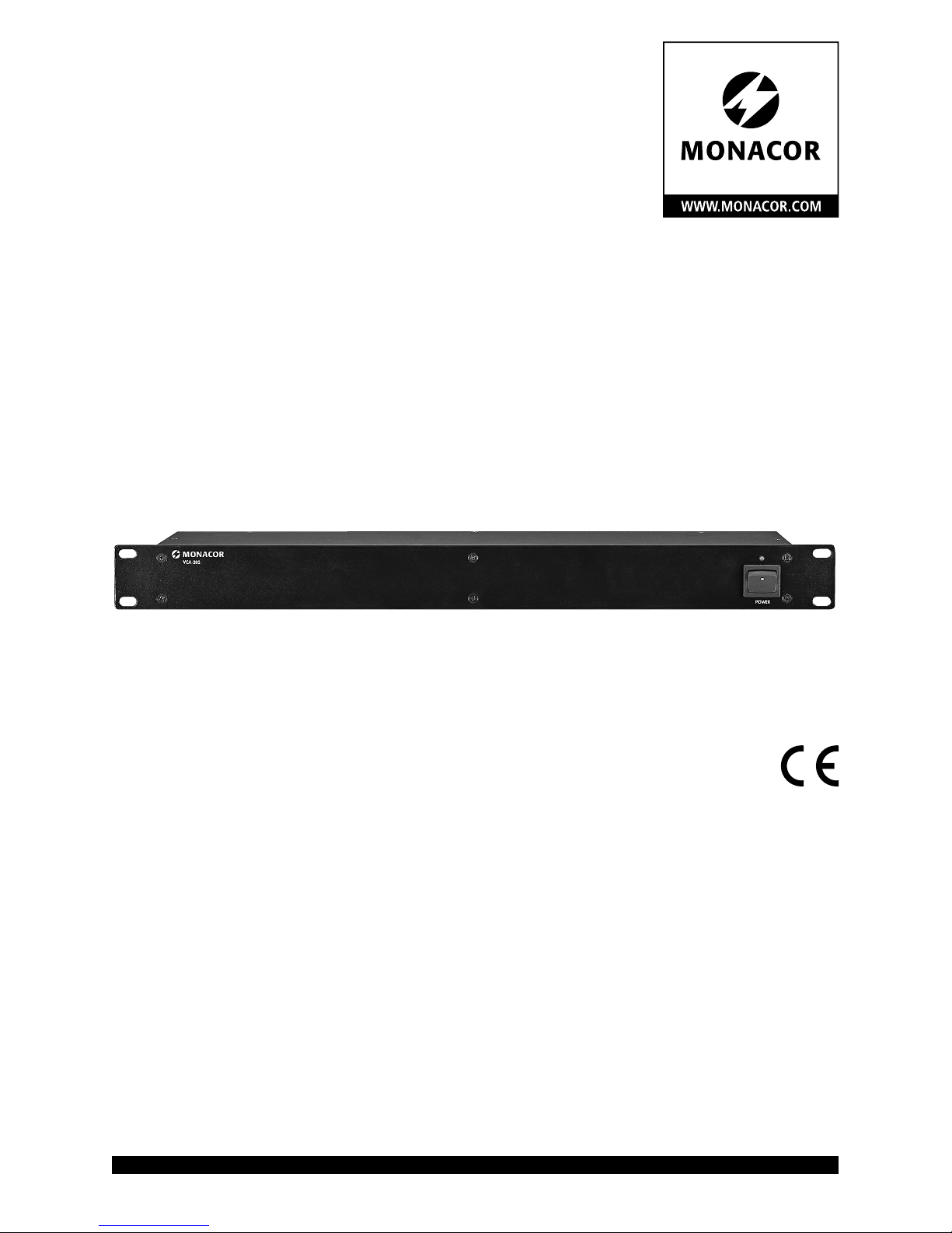
2-Kanal-Vorverstärker
zur Lautstärkeferneinstellung
2-Channel Preamplifier
for Remote Volume Control
Page 2

2
Page 3

3
ELECTRONICS FOR SPECIALISTS ELECTRONICS FOR SPECIALISTS ELECTRONICS FOR SPECIALISTS ELECTRONICS FOR SPECIALISTS
Deutsch ..........Seite 4
English ...........Page 6
Français ..........Page 8
Italiano...........Pagina 10
Español ..........Página 12
Polski ............Strona 14
Nederlands .......Pagina 16
Dansk ............Sida 16
Svenska ..........Sidan 17
Suomi............Sivulta 17
Page 4
4
Deutsch
POWER
VCA-202
1
2
➀
2-Kanal-Vorverstärker VCA-202
Diese Anleitung richtet sich an Benutzer mit
Grundkenntnissen in der Audiotechnik. Bitte
lesen Sie die Anleitung vor dem Betrieb gründlich durch und heben Sie sie für ein späteres
Nachlesen auf.
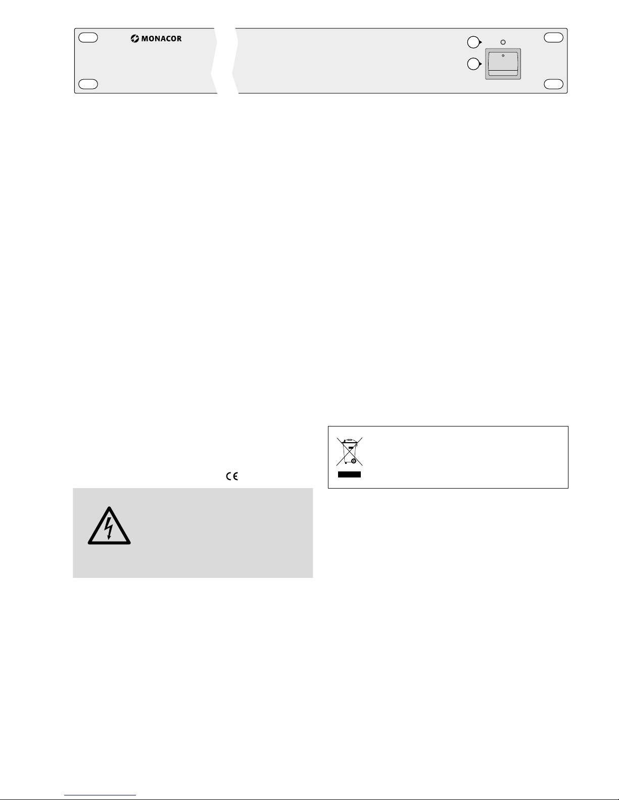
1 Übersicht
1 Ein- /Ausschalter
2 Betriebsanzeige
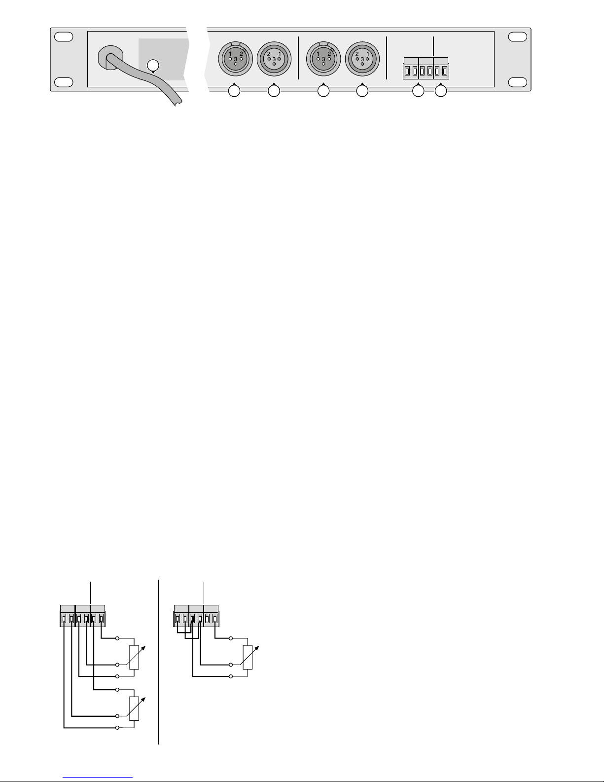
3
Netzkabel zum Anschluss an eine Steckdose
(230 V/ 50 Hz)
4 XLR-Ausgang, symmetrisch, mono
5 XLR-Eingang, symmetrisch, mono
6 Steckschraubklemmen*, Steuereingang
7
Steckschraubklemmen*, Ausgang ⎓ 10 V,
5 mA
2 Hinweise für den
sicherenGebrauch
Das Gerät entspricht allen relevanten Richtlinien
der EU und trägt deshalb das -Zeichen.
WARNUNG
Das Gerät wird mit lebensgefährlicher Netzspannung versorgt.
Nehmen Sie deshalb niemals
selbst Eingriffe daran vor! Es
besteht die Gefahr eines elektrischen Schlages.
•
Das Gerät ist nur zur Verwendung im Innenbereich geeignet. Schützen Sie es vor Tropfund Spritzwasser, hoher Luftfeuchtigkeit und
Hitze (zulässiger Einsatztemperaturbereich
0 – 40 °C).
•
Stellen Sie keine mit Flüssigkeit gefüllten Gefäße, z. B. Trinkgläser, auf das Gerät.
•
Nehmen Sie das Gerät nicht in Betrieb bzw.
ziehen Sie sofort den Netzstecker aus der
Steckdose,
1.
wenn sichtbare Schäden am Gerät oder
am Netzkabel vorhanden sind,
2.
wenn nach einem Sturz oder Ähnlichem
der Verdacht auf einen Defekt besteht,
3. wenn Funktionsstörungen auftreten.
Lassen Sie das Gerät in einer Fachwerkstatt
reparieren.
•
Ein beschädigtes Netzkabel darf nur durch
den Hersteller oder durch eine autorisierte
Fachwerkstatt ersetzt werden.
•
Ziehen Sie den Netzstecker nie am Kabel aus
der Steckdose, fassen Sie immer am Stecker
an.
•
Verwenden Sie zum Reinigen nur ein trockenes, weiches Tuch, niemals Chemikalien oder
Wasser.
•
Wird das Gerät zweckentfremdet, nicht richtig angeschlossen, falsch bedient oder nicht
fachgerecht repariert, kann keine Haftung für
daraus resultierende Sach- oder Personenschäden und keine Garantie für das Gerät
übernommen werden.
Soll das Gerät endgültig aus dem Betrieb genommen werden, übergeben
Sie es zur umweltgerechten Entsorgung einem örtlichen Recycling betrieb.
3 Einsatzmöglichkeiten
Dieser 2-Kanal-Vorverstärker ist für den Einsatz
in professionellen PA- oder Bühnenbeschallungsanlagen konzipiert. Mit ihm lässt sich der
Signalpegel für jeden Kanal separat durch eine
Gleichspannung fernsteuern.
An den Vorverstärker können Stereo- und
Mono-Geräte mit Line-Pegel (z. B. CD-Spieler,
Mischpulte, Tonbandgeräte) angeschlossen
werden.
Der Vorverstärker ist speziell für die Montage in ein Rack (482 mm / 19”) ausgelegt. Er
kann bei Bedarf aber auch frei aufgestellt werden. Für den Rackeinbau wird eine Höhe von
1 HE (Höheneinheit = 44,45 mm) benötigt.
* Die Anschlussklemmen lassen sich zur besseren Hand-
habung von ihrer Steckverbindung abziehen.
Page 5
5
Deutsch
POWER
VCA-202
CH 2OUTPUT INPUT CH 1OUTPUT INPUT
VCA CONTROL
0 –10 VDC
CH2 CH1
– +
DC OUT
10 Vmax.
5 mA
– + + +
230 V~/50Hz
4 45 5 6 7
3
1
2
➁
4 Gerät anschließen
Vor dem Anschließen von Geräten bzw. vor
dem Ändern bestehender Anschlüsse den Vorverstärker und die anzuschließenden Geräte
ausschalten.
1) Die Line-Tonquellen (z. B. CD-Spieler, Mischpult, Tonbandgerät) an die Eingangsbuchsen
INPUT (5) anschließen.
2) Den Endverstärker für die Lautsprecher oder
ein anderes nachfolgendes Gerät mit LineEingang an die Ausgangsbuchsen OUTPUT(4)
anschließen.
3) Die Steuerspannungen an die Schraubklemmen* (6) anschließen. Die Kabellänge und
der Kabelquerschnitt der Steuerleitungen sind
unkritisch.
Wenn keine externe Steuerspannung vorhanden ist, kann die an den Schraubklemmen* (7) bereitgestellte Ausgangsspannung
(10 V) genutzt werden. Dazu wird die Verwendung von Potentiometern mit einem
Wert von 10 kΩ und einer linearen Charakteristik empfohlen (z. B. VCA-202RN). Die
Potentiometer entsprechend der Abbildung
3 anschließen.
Wird eine Stereoquelle angeschlossen,
müssen die Steuereingänge (6) der beiden
Kanäle entsprechend Abb. 4 parallel geschaltet werden.
4)
Zuletzt den Stecker des Netzkabels (3) in eine
Steckdose (230 V/ 50 Hz) stecken.
CH 2 CH1
0–10VDC
– +
DC OUT
10 V/ max.5mA
– + + +
CH1
CH2
VCA CONTROL
VCA CONTROL
0–10VDC
CH 2 CH1
CH 2 CH1
– +
DC OUT
10 V/ max.5mA
– + + +
CH1 + CH2
0–10VDC
– +
DC OUT
10 V/ max.5mA
– + + +
CH1
CH2
➂
2-Kanalbetrieb
➃
Stereobetrieb
5 Bedienung
1) Vor dem Einschalten sollten die Steuerspannungen auf 0 V gestellt werden, um starke
Einschaltgeräusche zu vermeiden.
2) Das Gerät mit dem Ein- /Ausschalter POWER
(1) einschalten. Die rote Betriebsanzeige (2)
leuchtet.
3) Die angeschlossenen Geräte einschalten, zuletzt immer den Endverstärker für die Lautsprecher.
4)
Beim Ausschalten der Anlage immer zuerst
den Endverstärker abschalten.
5.1 Ausgangspegel einstellen
Die Einstellung des Ausgangspegels erfolgt mit
einer Gleichspannung. Der Regelbereich liegt
zwischen 0 und 10 V, wobei bei 0 V kein Ausgangspegel vorhanden ist. Der Ausgangspegel
steigt linear mit der Steuerspannung an. Die
maximale Verstärkung beträgt 1 (0 dB) und stellt
sich bei einer Steuerspannung von 10 V ein.
6 Technische Daten
Eingänge
2 × LINE, mono: . . . . 1 V/ 30 kΩ, sym.
2 × Steuereingang . . . 0 – 10 V (⎓) / 100 kΩ
Ausgänge
2 × LINE, mono: . . . . 1 V/ 600 Ω, sym.
1 × Hilfsspannung . . . 10 V (⎓) / 5 mA max.
Frequenzbereich: . . . . . . 20 – 20 000 Hz
Klirrfaktor: . . . . . . . . . . 0,1 %
Störabstand: . . . . . . . . . 70 dB, unbewertet
Stromversorgung: . . . . . 230 V/ 50 Hz / 10 VA
Einsatztemperatur: . . . . 0 – 40 °C
Abmessungen
(B × H × T):
. . . . . . . . . . 482 × 48 × 105 mm,
1 Höheneinheit
Gewicht:
. . . . . . . . . . . . 1,5 kg
Änderungen vorbehalten.
Diese Bedienungsanleitung ist urheberrechtlich für
MONACOR ® INTERNATIONAL GmbH & Co. KG geschützt.
Eine Reproduktion für eigene kommerzielle Zwecke – auch
auszugsweise – ist untersagt.
Page 6
6
English
POWER
VCA-202
1
2
➀
2-Channel Preamplifier VCA-202
These operating instructions are intended for
users with basic knowledge in audio technology.
Please read the instructions carefully prior to
operation and keep them for later reference.
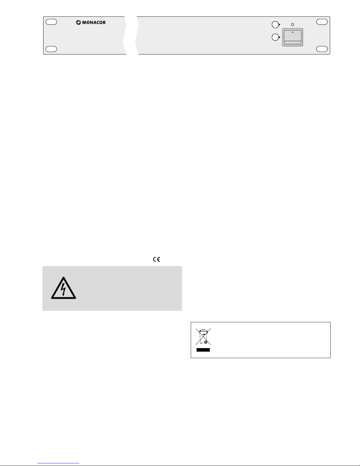
1 Overview
1 POWER switch
2 POWER LED
3
Mains cable for connection to a mains socket
(230 V/ 50 Hz)
4 XLR output, balanced, mono
5 XLR input, balanced, mono
6 Plug-in screw terminals*, control input
7
Plug-in screw terminals*, output ⎓ 10 V,
5 mA
* To make handling easier when connecting, the screw ter-
minals can be removed from their plug-in connections.
2 Safety Notes
This unit corresponds to all relevant directives of
the EU and is therefore marked with .
WARNING
The unit uses dangerous mains
voltage. Leave servicing to skilled
personnel only. Inexpert handling or modification of the unit
may result in electric shock.
•
The unit is suitable for indoor use only. Protect it against dripping water and splash
water, high air humidity and heat (admissible
ambient temperature range 0 – 40 °C).
•
Do not place any vessels filled with liquid, e. g.
drinking glasses, on the unit.
•
Do not operate the unit or immediately disconnect the mains plug from the socket
1.
if the unit or the mains cable is visibly dam
-
aged,
2. if a defect might have occurred after the
unit was dropped or suffered a similar accident,
3. if malfunctions occur.
In any case, the units must be repaired by
skilled personnel.
•
A damaged mains cable must only be replaced by the manufacturer or by authorized,
skilled personnel.
•
Never pull the mains cable to disconnect the
mains plug from the mains socket, always
seize the plug.
•
For cleaning only use a dry, soft cloth; never
use chemicals or water.
•
No guarantee claims for the unit and no liability for any resulting personal damage or
material damage will be accepted if the unit
is used for other purposes than originally intended, if it is not correctly connected, operated or not repaired in an expert way.
•
Important for UK Customers!
The wires in the mains lead of the power
supply unit are coloured in accordance with
the following code:
blue = neutral; brown = live
As the colours of the wires in the mains lead
of this appliance may not correspond with the
coloured markings identifying the terminals
in your plug, proceed as follows:
1. The wire which is coloured blue must be
connected to the terminal in the plug
which is marked with the letter N or
coloured black.
2.
The wire which is coloured brown must be
connected to the terminal which is marked
with the letter L or coloured red.
If the unit is to be put out of operation
definitively, take it to a local recycling
plant for a disposal which is not harmful to the environment.
3 Applications
This 2-channel preamplifier is designed for professional PA systems or for professional applications on stage. It allows to remote-control
the signal level separately for each channel by
a DC voltage.
It is possible to connect stereo and mono
units with line level (e. g. CD players, mixers,
tape recorders) to the preamplifier.
Page 7

7
English
POWER
VCA-202
CH 2OUTPUT INPUT CH 1OUTPUT INPUT
VCA CONTROL
0 –10 VDC
CH2 CH1
– +
DC OUT
10 Vmax.
5 mA
– + + +
230 V~/50Hz
4 45 5 6 7
3
1
2
➁
The preamplifier is especially suited for installation into a rack (482 mm / 19”). If required,
it can also be placed as desired. For rack installation a height of 1 RS (rack space = 44.45 mm)
is required.
4 Connection
Always switch off the preamplifier and the units
to be connected before making or changing any
connections!
1)
Connect the line audio sources (e. g. CD
player, mixer, tape recorder) to the jacks
INPUT (5).
2)
Connect the power amplifier for the speakers
or another subsequent unit with line input to
the jacks OUTPUT (4).
3)
Connect the control voltages to the screw
terminals* (6). The cable length and the cross
section of the control cables are uncritical.
If there is no external control voltage, the
output voltage (10 V) provided at the screw
terminals* (7) can be used. For this purpose, it
is recommended to use potentiometers with a
value of 10 kΩ and a linear characteristic (e. g.
VCA-202RN). Connect the potentiometers
according to fig. 3.
If a stereo source is connected, the control inputs (6) of the two channels have to
be connected in parallel according to fig. 4.
4) Finally connect the plug of the mains cable
(3) to a mains socket (230 V/ 50 Hz).
CH 2 CH1
0–10 VDC
– +
DC OUT
10 V/ max.5mA
– + + +
CH1
CH2
VCA CONTROL
VCA CONTROL
0–10 VDC
CH 2 CH1
CH 2 CH1
– +
DC OUT
10 V/ max.5mA
– + + +
CH1 + CH2
0–10 VDC
– +
DC OUT
10 V/ max.5mA
– + + +
CH1
CH2
➂
2-channel mode
➃
stereo mode
* To make handling easier when connecting, the screw ter-
minals can be removed from their plug-in connections.
5 Operation
1)
Prior to switching on, the control voltages
should be set to 0 V to prevent loud switching noise.
2) Switch on the unit with the POWER switch
(1). The red POWER LED (2) lights up.
3)
Switch on the units connected, always switch
on the power amplifier for the speakers last.
4)
When switching off the system, always switch
off the power amplifier first.
5.1 Adjusting the output level
The output level is adjusted with a DC voltage.
The control range is between 0 and 10 V, at 0 V
there is no output level. The output level will rise
linearly with the control voltage. The maximum
amplification is 1 (0 dB) and appears at a control
voltage of 10 V.
6 Specifications
Inputs
2 × LINE, mono: . . . . 1 V/ 30 kΩ, bal.
2 × control input: . . . 0 – 10 V (⎓)/ 100 kΩ
Outputs
2 × LINE, mono: . . . . 1 V/ 600 Ω, bal.
1 × auxiliary voltage: . 10 V (⎓)/ 5 mA max.
Frequency range: . . . . . 20 – 20 000 Hz
THD: . . . . . . . . . . . . . . . 0.1 %
S / N ratio: . . . . . . . . . . . 70 dB, unweighted
Power supply: . . . . . . . . 230 V/ 50 Hz / 10 VA
Ambient temperature: . . 0 – 40 °C
Dimensions (W × H × D): . 482 × 48 × 105 mm,
1 rack space
Weight:
. . . . . . . . . . . . 1.5 kg
Subject to technical modification.
All rights reserved by MONACOR ® INTERNATIONAL GmbH
& Co. KG. No part of this instruction manual may be
reproduced in any form or by any means for any commercial use.
Page 8

8
Français
POWER
VCA-202
1
2
➀
Préamplificateur 2 canaux VCA-202
Cette notice s’adresse aux utilisateurs avec des
connaissances techniques de base en audio.
Veuillez lire la présente notice avec attention
avant le fonctionnement et conservez-la pour
pouvoir vous y reporter ultérieurement.
1 Présentation
1 Interrupteur Marche /Arrêt
2 Témoin de fonctionnement
3 Cordon secteur à relier à une prise secteur
230 V/ 50 Hz
4 Sortie XLR, symétrique, mono
5 Entrée XLR, symétrique, mono
6 Bornes à pinces*, entrée commande
7 Bornes à pinces*, sortie ⎓ 10 V, 5 mA
* Les bornes à pinces peuvent être retirées de leur empla-
cement pour une meilleure manipulation.
2 Conseils d’utilisation et
desécurité
Cet appareil répond à toutes les directives nécessaires de l’Union Européenne et porte donc
le symbole .
AVERTIS-
SEMENT
Cet appareil est alimenté par une
tension dangereuse. Ne touchez
jamais l’intérieur de l’appareil
car, en cas de mauvaise manipulation, vous pourriez subir une
décharge électrique.
•
L’appareil n’est conçu que pour une utilisation
en intérieur. Protégez-le de tout type de projections d’eau, des éclaboussures, d’une humidité
élevée et de la chaleur (plage de température
de fonctionnement autorisée : 0 – 40 °C).
•
En aucun cas, vous ne devez poser d’objet
conte nant du liquide ou un verre sur l’appareil.
•
Ne le faites jamais fonctionner et débranchez-le immédiatement lorsque :
1. des dommages sur l’appareil et sur le cordon secteur apparaissent
2.
après une chute ou accident similaire ...,
l’appareil peut présenter un défaut.
3. des dysfonctionnements apparaissent.
Dans tous les cas, les dommages doivent être
réparés par un technicien spécialisé.
•
Tout cordon secteur endommagé ne doit être
remplacé que par le fabricant ou un technicien habilité.
•
Ne débranchez jamais l’appareil en tirant
sur le cordon secteur, tenez-le toujours par
la prise.
•
Pour le nettoyage, utilisez toujours un chiffon sec et doux, en aucun cas de produits
chimiques ou d’eau.
•
Nous déclinons toute responsabilité en cas de
dommages matériels ou corporels résultants
si l’appareil est utilisé dans un but autre que
celui pour lequel il a été conçu, s’il n’est pas
correctement branché ou utilisé ou s’il n’est
pas réparé par une personne habilitée, en
outre, la garantie deviendrait caduque.
Lorsque l’appareil est définitivement retiré
du service, vous devez le déposer dans une
usine de recyclage adaptée pour contribuer
à son élimination non polluante.
CARTONS ET EMBALLAGE
PAPIER À TRIER
3 Possibilités d’utilisation
Ce préamplificateur 2 canaux est conçu pour
une utilisation dans des installations professionnelles de sonorisation ou sur scène. Il permet de
gérer, à distance, le niveau de signal séparément
pour chaque canal, par une tension continue.
Il est possible de relier au préamplificateur des
appareils stéréo et mono à niveau Ligne (p. ex.
lecteurs CD, tables de mixage, enregistreurs).
Le préamplificateur est spécialement conçu
pour un montage dans un rack 19” (482 mm).
Si besoin, il peut être posé librement. Pour un
montage en rack, une hauteur de une unité
(= 44,45 mm) est nécessaire.
Page 9

9
Français
POWER
VCA-202
CH 2OUTPUT INPUT CH 1OUTPUT INPUT
VCA CONTROL
0 –10 VDC
CH2 CH1
– +
DC OUT
10 Vmax.
5 mA
– + + +
230 V~/50Hz
4 45 5 6 7
3
1
2
➁
4 Branchements
Avant de brancher les appareils ou de modifier
les branchements existants, éteignez le préamplificateur et les appareils à relier.
1)
Connectez les sources audio ligne (par
exemple lecteur CD, table de mixage, enregistreur) aux prises d’entrée INPUT (5).
2)
Reliez l’amplificateur final pour les hautparleurs ou un autre appareil suivant avec
entrée ligne aux prises de sortie OUTPUT (4).
3)
Connectez les tensions de commande aux
bornes à pinces* (6). La longueur et la section des câbles de commande ne sont pas
prépondérantes.
Si aucune tension de commande externe
n’existe, la tension de sortie (10 V) mise à
disposition aux bornes à pinces* (7) peut
être utilisée. L’utilisation de potentiomètres
avec une valeur de 10 kΩ et une caractéristique linéaire est, dans ce cas, recommandée
(p. ex. VCA-202RN). Reliez les potentiomètres
conformément au schéma 3.
Si une source stéréo est reliée, les entrées
de commande (6) des deux canaux doivent
être branchées en parallèle selon le schéma 4.
4) Enfin, reliez la prise du cordon secteur (3) à
une prise secteur 230 V/ 50 Hz.
CH 2 CH1
0–10 VDC
– +
DC OUT
10 V/ max.5mA
– + + +
CH1
CH2
VCA CONTROL
VCA CONTROL
0–10 VDC
CH 2 CH1
CH 2 CH1
– +
DC OUT
10 V/ max.5mA
– + + +
CH1 + CH2
0–10 VDC
– +
DC OUT
10 V/ max.5mA
– + + +
CH1
CH2
➂
Mode 2 canaux
➃
Mode stéréo
* Les bornes à pinces peuvent être retirées de leur empla-
cement pour une meilleure manipulation.
5 Fonctionnement
1)
Avant d’allumer, il faudrait mettre les tensions
de commande sur 0 V pour éviter les bruits
forts à l’allumage.
2)
Allumez l’appareil avec l’interrupteur POWER
Marche /Arrêt (1), le témoin rouge de fonctionnement (2) brille.
3) Allumez les appareils reliés, allumez toujours
l’amplificateur final pour les haut-parleurs en
dernier.
4)
Lorsque vous éteignez l’installation, éteignez
toujours en premier l’amplificateur final.
5.1 Réglage du niveau de sortie
Le réglage du niveau de sortie s’effectue avec
une tension continue. La plage de réglage est
entre 0 et 10 V, à 0 V, il n’y a aucun niveau de
sortie. Le niveau de sortie augmente de manière
linéaire en fonction de la tension de commande.
L’amplification maximale est de 1 (0 dB) et apparaît pour une tension de commande de 10 V.
6 Caractéristiques techniques
Entrées
2 × LINE, mono : . . . . . . 1 V/ 30 kΩ, sym.
2 × entrée commande : 0 – 10 V (⎓) / 100 kΩ
Sorties
2 × LINE, mono : . . . . . . 1 V/ 600 Ω, sym.
1 × tension auxilaire : . . 10 V (⎓)/ 5 mA max.
Bande passante : . . . . . . . . 20 – 20 000 Hz
Taux de distorsion : . . . . . . 0,1 %
Rapport signal / bruit : . . . . 70 dB, non pondéré
Alimentation : . . . . . . . . . . 230 V/ 50 Hz / 10 VA
Température fonc. : . . . . . . 0 – 40 °C
Dimensions (l × h × p) : . . . 482 × 48 × 105 mm,
1 U
Poids : . . . . . . . . . . . . . . . . 1,5 kg
Tout droit de modification réservé.
Notice d’utilisation protégée par le copyright de
MONACOR ® INTERNATIONAL GmbH & Co. KG. Toute
reproduction même partielle à des fins commerciales est
interdite.
Page 10

10
Italiano
POWER
VCA-202
1
2
➀
Preamplificatore a 2 canali VCA-202
Queste istruzioni sono rivolte a utenti con conoscenze base nella tecnica audio. Vi preghiamo di
leggerle attentamente prima dell’installazione e
di conservarle per un uso futuro.
1 Panoramica
1 Interruttore on / off
2 Spia di funzionamento
3
Cavo di rete per il collegamento con una
spina di rete (230 V/ 50 Hz)
4 Uscita XLR, simmetrica, mono
5 Ingresso XLR, simmetrico, mono
6 Morsetti a vite*, ingresso di comando
7 Morsetti a vite*, uscita ⎓ 10 V, 5m A
2 Avvertenze di sicurezza
Quest’apparecchio è conforme a tutte le direttive rilevanti dell’UE e pertanto porta la sigla .
AVVERTIMENTO
L’apparecchio funziona con
pericolosa tensione di rete.
Non intervenire mai personalmente al suo interno! La
manipolazione scorretta può
provocare una scarica elettrica
pericolosa.
•
Lo strumento è previsto solo per l’uso all’interno di locali. Proteggerlo dall’acqua gocciolante e dagli spruzzi d’acqua, da alta umidità
dell’aria e dal calore (temperatura d’impiego
ammessa fra 0 e 40 °C).
•
Non depositare sull’apparecchio dei contenitori riempiti di liquidi, p. es. bicchieri.
•
Non mettere in funzione l’apparecchio e staccare subito la spina rete se:
1. l’apparecchio o il cavo rete presentano dei
danni visibili;
2. dopo una caduta o dopo eventi simili sussiste il sospetto di un difetto;
3.
l’apparecchio non funziona correttamente.
Per la riparazione rivolgersi sempre ad un’officina competente.
•
Il cavo rete, se danneggiato, deve essere sostituito solo dal costruttore o da un laboratorio
autorizzato.
•
Staccare il cavo rete afferrando la spina, senza
ti rare il cavo.
•
Per la pulizia usare solo un panno morbido,
asciutto; non impiegare in nessun caso prodotti chimici o acqua.
•
Nel caso d’uso improprio, di collegamenti
sbagliati, d’impiego scorretto o di riparazione
non a regola d’arte dello strumento, non si
assume nessuna re sponsabilità per eventuali
danni consequenziali a persone o a cose e
non si assume nessuna garanzia per lo strumento.
Se si desidera eliminare l’apparecchio
definitivamente, consegnarlo per lo
smaltimento ad un’istituzione locale
per il rici claggio.
3 Possibilità d’impiego
Questo preamplificatore a 2 canali è stato realizzato per l’impiego in impianti professionali
di sonorizzazioni PA o di spettacolo. Permette
di telecomandare il livello dei segnali per ogni
canale separatamente per mezzo di una tensione continua.
Al preamplificatore si possono collegare apparecchi stereo e mono con livello Line (p. es.
lettori CD, mixer, registratori).
Il preamplificatore è previsto specialmente
per il mon taggio in un rack (482 mm / 19”). Tuttavia, se ne cessario, può essere collocato anche
liberamente. Per il montaggio in un rack è richiesta un’unità di altezza RS (= 44,45 mm).
* Per maggiore comodità nei collegamenti, i morsetti si
possono sfilare dalla loro sede.
Page 11

11
Italiano
POWER
VCA-202
CH 2OUTPUT INPUT CH 1OUTPUT INPUT
VCA CONTROL
0 –10 VDC
CH2 CH1
– +
DC OUT
10 Vmax.
5 mA
– + + +
230 V~/50Hz
4 45 5 6 7
3
1
2
➁
4 Collegamento
Prima di eseguire i collegamenti o di modificare
quelli esistenti occorre spegnere il preamplificatore e gli apparecchi da collegare.
1)
Collegare le sorgenti Line (p. es. lettori CD,
mixer, registratori) con le prese d’ingresso
INPUT (5).
2)
Collegare il finale per gli altoparlanti, o un
altro apparecchio a valle con ingresso Line,
con le prese d’uscita OUTPUT (4).
3) Collegare le tensioni di comando con i morsetti a vite* (6). La lunghezza dei cavi nonché
la sezione dei cavi di comando non hanno
importanza.
Se non è presente nessuna tensione
esterna di comando si può utilizzare la tensione d’uscita (10 V) presente ai morsetti* (7).
In questo caso si consiglia l’impiego di potenziometri di 10 kΩ con caratteristica lineare
(p. es. VCA-202RN). Collegare i potenziometri
come da figura 3.
Se si collega una sorgente stereo, gli ingressi di comando (6) dei due canali devono
essere collegati in parallelo coma da fig. 4.
4) Alla fine inserire la spina del cavo rete (3) in
una presa di rete (230 V/ 50 Hz).
CH 2 CH1
0–10 VDC
– +
DC OUT
10 V/ max.5mA
– + + +
CH1
CH2
VCA CONTROL VCA CONTROL
0–10 VDC
CH 2 CH1
CH 2 CH1
– +
DC OUT
10 V/ max.5mA
– + + +
CH1 + CH2
0–10 VDC
– +
DC OUT
10 V/ max.5mA
– + + +
CH1
CH2
➂
Modo 2 canale
➃
Modo stereo
5 Funzionamento
1) Prima di accendere, portare tutte le tensioni
di co mando su 0 V, per escludere forti rumori
di commutazione.
2)
Accendere l’apparecchio con l’interruttore
on / off POWER (1). Si accende la spia rossa di
funzionamento (2).
3)
Accendere gli apparecchi collegati; sempre
per ultimo il finale per gli altoparlanti.
4) Spegnendo l’impianto, spegnere sempre per
primo il finale.
5.1 Regolazione del livello d’uscita
La regolazione del livello d’uscita avviene con
una tensione continua. Il campo di regolazione
è fra 0 e 10 V, dove 0 V significa che non è presente nessun livello d’u scita. Il livello d’uscita sale
in modo lineare con la ten sione di comando. La
massima amplificazione è di 1 (0 dB) e si ottiene
con una tensione di comando di 10 V.
6 Dati tecnici
Ingressi
2 × LINE, mono: . . . . 1 V/ 30 kΩ, simm.
2 × ingresso
di comando: . . . . 0 – 10 V (⎓) / 100 kΩ
Uscite
2 × LINE, mono: . . . . 1 V/ 600 Ω, simm.
1 × tensione
ausiliaria: . . . . . . . 10 V (⎓) / 5 mA max.
Gamma di frequenze: . . 20 – 20 000 Hz
Fattore di distorsione: . . 0,1 %
Rapporto S / R: . . . . . . . . 70 dB, non valutato
Alimentazione: . . . . . . . 230 V/ 50 Hz / 10 VA
Temperatura d’esercizio: 0 – 40 °C
Dimensioni (l × h × p): . . 482 × 48 × 105 mm,
1unità d’altezza
Peso:
. . . . . . . . . . . . . . . 1,5 kg
Con riserva di modifiche tecniche.
La MONACOR ® INTERNATIONAL GmbH & Co. KG si
riserva ogni diritto di elaborazione in qualsiasi forma delle
presenti istruzioni per l’uso. La riproduzione – anche parziale – per propri scopi commerciali è vietata.
* Per maggiore comodità nei collegamenti, i morsetti si
possono sfilare dalla loro sede.
Page 12

12
Español
POWER
VCA-202
1
2
➀
Preamplificador de 2 Canales VCA-202
Estas instrucciones de funcionamiento van dirigidas a usuarios con conocimientos básicos en
audio. Lea atentamente estas instrucciones de
funcionamiento antes de utilizar el aparato y
guárdelas para usos posteriores.
1 Vista General
1 Interruptor POWER
2 Indicador POWER
3
Cable de corriente para conectar a una toma
(230 V/ 50 Hz)
4 Salida XLR, simétrica, mono
5 Entrada XLR, simétrica, mono
6 Terminales de tornillo*, entrada de control
7
Terminales de tornillos*, salida ⎓ 10 V, 5 mA
2 Notas de Seguridad
Este aparato cumple con todas la directivas relevantes de la UE y por lo tanto está marcado
con el símbolo .
ADVERTENCIA El aparato utiliza un voltaje pe-
ligroso. Deje el mantenimiento
en manos del personal cualificado. El manejo inexperto
puede provocar una descarga.
•
El aparato está adecuado para utilizarse sólo
en interiores. Protéjalo de goteos y salpicaduras, elevada humedad del aire y calor (tempe
-
ratura ambiente admisible: 0 – 40 °C).
•
No coloque ningún recipiente con líquido
encima del aparato, p. ej. un vaso.
•
No utilice el aparato o inmediatamente desconéctelo del corriente si:
1.
El aparato o el cable de corriente están
visiblemente dañados.
2.
El aparato ha sufrido daños después de
una caída o accidente similar.
3. No funciona correctamente.
Sólo el personal técnico puede reparar el aparato bajo cualquier circunstancia.
•
Un cable de corriente dañado sólo puede reemplazarse por el fabricante o por el personal
cualificado.
•
No tire nunca del cable de corriente para
desconectarlo del corriente, tire siempre del
conector.
•
Utilice sólo un paño suave y seco para la limpieza; no utilice nunca ni agua ni productos
químicos.
•
No podrá reclamarse garantía o responsabilidad alguna por cualquier daño personal
o material resultante si el aparato se utiliza
para otros fines diferentes a los originalmente
concebidos, si no se conecta o utiliza adecuadamente, o si no se repara por expertos.
Si va a poner el aparato definitivamente fuera del servicio, llévelo a la
planta de reciclaje mas cercana para
que su eliminación no sea perjudicial
para el medioambiente.
3 Aplicaciones
Este preamplificador de 2 canales está diseñado
para utilizarse en instalaciones profesionales de
megafonía o escenario. Permite el control remoto separado de los niveles de señal para cada
canal mediante una tensión continua.
Se pueden conectar aparatos estéreo y
mono de nivel de línea (p. ej. lectores CD, mezcladores, grabadores) al preamplificador.
El preamplificador está diseñado para la instalación en un rack (482 mm / 19”), pero también
se puede colocar como desee. Para la instalación
en un rack, se nececita 1 U (= 44,45 mm).
* Para que el manejo sea más sencillo, los terminales de
tornillo se pueden quitar de su conexión.
Page 13

13
Español
POWER
VCA-202
CH 2OUTPUT INPUT CH 1OUTPUT INPUT
VCA CONTROL
0 –10 VDC
CH2 CH1
– +
DC OUT
10 Vmax.
5 mA
– + + +
230 V~/50Hz
4 45 5 6 7
3
1
2
➁
4 Conexión
Antes de hacer o modificar cualquier conexión,
desconecte el preamplificador y los aparatos que
hay que conectar.
1) Conecte las fuentes de audio de línea (p. ej.
lector CD, mezclador, grabador) a las tomas
de entrada INPUT (5).
2)
Conecte el amplificador de potencia para
los altavoces u otro aparato siguiente con
entrada de línea a las tomas de salida
OUTPUT (4).
3) Conecte las tensiones de control a los terminales de tornillo* (6). La longitud y la sección
de los cables de control no son críticas.
Si no hay tensión de control externa, se
puede utilizar la tensión de salida (10 V) disponible en los terminales de tornillo* (7). Para
ello, se recomienda utilizar potenciómetros
con un valor de 10 kΩ y una característica
lineal (p. ej. VCA-202RN). Conecte los potenciómetros según la figura 3.
Si se conecta una fuente estéreo, las
entradas de control (6) de los dos canales
tienen que ser conectadas en paralelo según
la figura 4.
4) Finalmente conecte el conector del cable de
corriente (3) a una toma (230 V/ 50 Hz).
CH 2 CH1
0–10 VDC
– +
DC OUT
10 V/ max.5mA
– + + +
CH1
CH2
VCA CONTROL
VCA CONTROL
0–10 VDC
CH 2 CH1
CH 2 CH1
– +
DC OUT
10 V/ max.5mA
– + + +
CH1 + CH2
0–10 VDC
– +
DC OUT
10 V/ max.5mA
– + + +
CH1
CH2
➂
Modo de 2 de canales ➃ Modo estéreo
5 Funcionamiento
1) Antes de conectar el preamplificador, ponga
las tensiones de control en 0 V para prevenir
ruido de conexión fuerte.
2)
Conecte el aparato con el interruptor POWER
(1). El indicador rojo POWER (2) se ilumina.
3)
Enciende los aparatos conectados, finalmente
el amplificador de potencia para los altavoces.
4)
Después del funcionamiento, primero apague
el amplificador de potencia.
5.1 Ajuste del nivel de salida
El nivel de salida se ajusta con una tensión continua. El rango de ajuste es entre 0 y 10 V; a
0 V, no hay ningún nivel de salida. El nivel de
salida aumenta de forma lineal con la tensión de
control. La amplificación máxima es de 1 (0 dB);
se obtiene con una tensión de control de 10 V.
6 Especificaciones
Entradas
2 × LINE, mono: . . . . .1 V/ 30 kΩ, sim.
2 × entrada de control: 0 – 10 V/ 100 kΩ
Salidas
2 × LINE, mono: . . . . .1 V/ 600 Ω, sim.
1 × tensión auxiliar: . . .10 V (⎓) / 5 mA máx.
Rango de frecuencias: . . .20 – 20 000 Hz
THD: . . . . . . . . . . . . . . . .0,1 %
Relación señal / ruido: . . . .70 dB, no ponderada
Alimentación: . . . . . . . . .230 V/ 50 Hz / 10 VA
Temperatura ambiente: . .0 – 40 °C
Dimensiones (B × H × P): .482 × 48 × 105 mm,
1 U
Peso: . . . . . . . . . . . . . . . .1,5 kg
Sujeto a modificaciones técnicas.
Manual de instrucciones protegido por el copyright de
MONACOR ® INTERNATIONAL GmbH & Co. KG. Toda
reproducción mismo parcial para fines comerciales está
prohibida.
* Para que el manejo sea más sencillo, los terminales de
tornillo se pueden quitar de su conexión.
Page 14

14
Polski
POWER
VCA-202
1
2
➀
Dwukanałowy przedwzmacniacz
VCA-202
Niniejsza instrukcja przeznaczona jest dla użytkowników posiadających co najmniej podstawową wiedzą z zakresu technologii audio. Przed
rozpoczęciem użytkowania proszę zapoznać się
z instrukcją, a następnie zachować ją do wglądu.
1 Elementy użytkowe i połączenia
1 Włącznik zasilania
2 Wskaźnik zasilania
3 Kabel zasilający (sieć 230 V/ 50 Hz)
4 Wyjście typu XLR, symetryczne, mono
5 Wejście typu XLR, symetryczne, mono
6
Gniazda zakręcane (wyciągane*), wejścia
steru jące
7
Gniazda zakręcane (wyciągane*), wyjście
⎓10 V, 5 mA
2 Środki ostrożności
Urządzenie spełnia wymogi dyrektyw obowiązujących w Unii Europejskiej, posiada więc oznakowanie .
UWAGA
Urządzenie jest zasilane niebezpie cznym dla życia napięciem
zmiennym. Obsługę techniczna
urządzenia należy zlecić osobom
upowa żnionym aby uniknąć ryzyka porażenia prądem.
•
Urządzenie jest przeznaczone tylko do użytku
wewnątrz pomieszczeń. Należy chronić przed
dostaniem się jakiejkolwiek cieczy do środka
urządzenia, dużą wilgotnością oraz ciepłem
(temperatura otoczenia powinna wynosić od
0 – 40 °C).
•
Nie wolno stawiać na urządzeniu żadnych
naczyń wypełnionych cieczami, np.: szklanek
z napojami.
•
Nie wolno używać oraz należy natychmiast
odłączyć urządzenie od zasilania:
1. Jeżeli widoczne są jakiekolwiek uszkodzenia urządzenia lub kabla zasilającego.
2.
Jeżeli urządzenie upadło lub uległo podobnemu wypadkowi, który mógł spowodować jego uszkodzenie.
3. Jeżeli występują nieprawidłowości w działaniu urządzenia.
W każdym z powyższych przypadków urządzenie musi zostać poddane naprawie przez
odpowiednio wyszkolony personel.
•
Uszkodzony kabel sieciowy może być wymieniany jedynie przez producenta lub przeszkolony personel.
•
Nie wolno ciągnąć za kabel zasilający, chcąc
go odłączyć należy trzymać za wtyczkę.
•
Do czyszczenia urządzenia zawsze używać
czystego i suchego kawałka materiału; nigdy
nie należy używać wody, ani środków chemicznych.
•
Nie ponosi się odpowiedzialności za wynikłe uszkodzenia sprzętu lub obrażenia użytkownika w przypadku, gdy urządzenie jest
wykorzystywane w innych celach niż to się
przewiduje lub, jeśli jest nieodpowiednio zainstalowane, użytkowane lub naprawiane.
Aby nie zaśmiecać środowiska po cał
kowitym zakończeniu eksploatacji urzą
dzeń należy je oddać do punktu recyklingu.
3 Zastosowanie
VCA-202 jest dwukanałowym przedwzmacniaczem przeznaczonym do zastosowania w
systemach PA (z ang. Public Adress) lub na scenie. Sterowanie poziomem głośności odbywa
się zdalnie (napięciem stałym) i niezależnie dla
każdego kanału.
Do przedwzmacniacza można podłączyć
urządzenia stereofoniczne lub monofoniczne,
które na wyjściu mają poziom liniowy (np. odtwarzacz CD, mikser, magnetofon).
VCA-202 jest przeznaczony do montażu w
szafie rackowej (482 mm / 19”): wymagana jest
*Dla wygody podłączania, gniazda te można wyjąć.
Page 15

15
Polski
POWER
VCA-202
CH 2OUTPUT INPUT CH 1OUTPUT INPUT
VCA CONTROL
0 –10 VDC
CH2 CH1
– +
DC OUT
10 Vmax.
5 mA
– + + +
230 V~/50Hz
4 45 5 6 7
3
1
2
➁
wolna przestrzeń 1 U (1 U = 44,45 mm), jednak
można go także położyć na półce w zależności
od potrzeb.
4 Podłączanie urządzenia
Przed podłączaniem urządzenia lub zmianą już
istniejących połączeń, należy wyłączyć przed
wzmacniacz oraz współpracujące z nim jednostki.
1)
Podłączyć źródła liniowe (np. odtwarzacz CD,
mikser, magnetofon) do gniazd INPUT (5).
2)
Do gniazd wyjściowych OUTPUT (4) podłączyć wzmacniacz lub aktywne zestawy głośnikowe.
3)
Do gniazd zakręcanych (6) podłączyć napięcie
sterujące. Długość kabli połączeniowych nie
odgrywa większej roli.
Jeśli nie dysponujemy zewnętrznym
napięciem sterującym, można wykorzystać
gniazda* (7) na których panuje napięcie 10 V.
Wtym celu należy wykorzystać potencjometry o charakterystyce liniowej i rezystancji
10 kΩ (np. VCA-202RN). Na rys. 3 pokazano
sposób podłączania potencjometrów.
Na rys. 4 pokazano sposób podłączania
potencjometru w przypadku podłączania urządzenia stereofonicznego.
4)
Na końcu należy podłączyć wtyczkę do
gniazdka sieciowego 230 V/ 50 Hz.
CH 2 CH1
0–10 VDC
– +
DC OUT
10 V/ max.5mA
– + + +
CH1
CH2
VCA CONTROL
VCA CONTROL
0–10 VDC
CH 2 CH1
CH 2 CH1
– +
DC OUT
10 V/ max.5mA
– + + +
CH1 + CH2
0–10 VDC
– +
DC OUT
10 V/ max.5mA
– + + +
CH1
CH2
➂
tryb 2-kanałowe
➃
tryb stereo
5 Obsługa
1)
Przed włączeniem przedwzmacniacza, aby
uniknąć stuku włączenia, napięcie sterujące
głośnością powinno być ustawione na 0 V.
2)
Włączyć przedwzmacniacz przyciskiem
POWER (1). Zapali się wskaźnik POWER (2).
3)
Włączyć podłączone urządzenia, wzmacniacz
lub aktywne zestawy głośnikowe należy zawsze włączać jako ostatnie.
4) Przy wyłączaniu systemu, jako pierwszy wyłączyć wzmacniacz.
5.1 Ustawianie poziomu wyjściowego
Poziom wyjściowy przedwzmacniacza jest sterowany napięciem stałym w przedziale od 0 do
10 V: przy napięciu 0 V, na wyjściu sygnał ma
wartość minimalną, natomiast podanie napięcia
sterującego 10 V odpowiada maksymalnemu
wzmocnieniu równemu 1 (0 dB). Regulacja poziomu wyjściowego jest liniowa.
6 Dane techniczne
Wejścia
2 × LINE, mono: . . . . 1 V/ 30 kΩ, symetryczne
2 × wejście sterujące: 0 – 10 V (⎓) / 100 kΩ
Wyjścia
2 × LINE, mono: . . . . 1 V/ 600 Ω, symetryczne
1 × napięcie
pomocnicze: . . . . 10 V (⎓) / 5 mA maks.
Pasmo przenoszenia: . . . 20 – 20 000 Hz
THD: . . . . . . . . . . . . . . 0,1 %
Stosunek S / N: . . . . . . . . 70 dB, nieważony
Zasilanie: . . . . . . . . . . . . 230 V/ 50 Hz / 10 VA
Temperatura otoczenia: . 0 – 40 °C
Wymiary (S × W × G): . . 482 × 48 × 105 mm,
1 U
Waga: . . . . . . . . . . . . . . 1,5 kg
Z zastrzeżeniem do możliwych zmian.
Instrukcje obsługi są chronione prawem copyright
for MONACOR ® INTERNATIONAL GmbH & Co. KG.
Przetwarzanie całości lub części instrukcji dla osobistych
korzyści finansowych jest zabronione.
Page 16

16
Nederlands
Dansk
VCA-202
Læs nedenstående sikkerhedsoplysninger
opmærksomt igennem før ibrugtagning af
enheden. Bortset fra sikkerhedsoplysningerne
henvises til den engelske tekst.
Vigtige sikkerhedsoplysninger
Denne enhed overholder alle relevante EU- diektiver
og er som følge deraf mærket .
ADVERSAL Enheden benytter livsfarlig net spæn
ding. For at undgå fare for elektrisk
stød må kabinettet ikke åbnes.
Overlad servicering til auto riseret
personel.
•
Enheden er kun beregnet til indendørs brug.
Beskyt den mod vanddråber og -stænk, høj
luftfugtighed og varme (tilladt omgivelsestemperatur 0 – 40 °C).
•
Undgå at placere væskefyldte genstande, som
f. eks. glas, ovenpå enheden.
•
Tag ikke enheden i brug og tag straks stikket ud
af stikkontakten i følgende tilfælde:
1.
hvis der er synlig skade på enheden eller
netkablet,
2. hvis der kan være opstået skade, efter at enheden er tabt eller lignende,
3. hvis der forekommer fejlfunktion.
Enheden skal altid repareres af autoriseret personel.
•
Et beskadiget netkabel må kun repareres af producenten eller af autoriseret personel.
•
Tag aldrig netstikket ud af stikkontakten ved at
trække i kablet, tag fat i selve stikket.
•
Til rengøring må kun benyttes en tør, blød klud;
der må under ingen omstændigheder benyttes
kemikalier eller vand.
•
Hvis enheden benyttes til andre formål, end den
oprindeligt er beregnet til, hvis den ikke er tilsluttet korrekt, hvis den betjenes forkert, eller
hvis den ikke repareres af autoriseret personel,
omfattes eventuelle skader ikke af garantien.
Hvis enheden skal tages ud af drift for
bestandigt, skal den bringes til en lokal
genbrugsstation for bortskaffelse.
Alle rettigheder til denne brugsvejledning tilhører
MONACOR ® INTERNATIONAL GmbH & Co. KG. Ingen
dele af denne vejledning må reproduceres under ingen
omstændigheder til kommerciel anvendelse.
VCA-202
Lees aandachtig de onderstaande veiligheidsvoorschriften, alvorens het apparaat in gebruik te nemen. Voor meer informatie over
de bediening van het apparaat raadpleegt u
de anderstalige handleidingen.
Veiligheidsvoorschriften
Het apparaat is in overeenstemming met alle relevante
EU-Richtlijnen en is daarom gekenmerkt met .
WAAR-
SCHUWING
De netspanning van het apparaat is
levensgevaarlijk. Open het apparaat
niet, want door onzorgvuldige in grepen loopt u het risico van elektrische
schokken.
•
Het apparaat is enkel geschikt voor gebruik
binnenshuis. Vermijd druip- en spatwater, uitzonderlijk warme plaatsen en plaatsen met een
hoge vochtigheid (toegestaan omgevingstemperatuurbereik: 0 – 40 °C).
•
Plaats geen bekers met vloeistof zoals drinkglazen etc. op het apparaat.
•
Schakel het apparaat niet in resp. trek onmiddellijk de stekker uit het stopcontact:
1. wanneer het apparaat of het netsnoer zichtbaar beschadigd is,
2.
wanneer er een defect zou kunnen optreden
nadat het apparaat bijvoorbeeld is gevallen,
3. wanneer het apparaat slecht functioneert.
Het apparaat moet in elk geval hersteld worden
door een gekwalificeerd vakman.
Een beschadigd netsnoer mag enkel door de
fabrikant of door een gekwalificeerd persoon
hersteld worden.
•
Trek de stekker nooit met het snoer uit het stopcontact, maar met de stekker zelf.
•
Verwijder het stof met een droge, zachte doek.
Gebruik zeker geen water of chemicaliën.
•
In geval van ongeoorloofd of verkeerd gebruik,
verkeerde aansluiting, foutieve bediening of van
herstelling door een niet-gekwalificeerd persoon
vervalt de garantie en de verantwoordelijkheid
voor hieruit resulterende materiële of lichamelijke schade.
Wanneer het apparaat definitief uit bedrijf wordt genomen, bezorg het dan
voor milieuvriendelijke verwerking aan
een plaatselijk recyclagebedrijf.
Deze gebruiksaanwijzing is door de auteurswet beschermd eigendom van MONACOR ® INTER NATIONAL
GmbH& Co. KG. Een reproductie – ook gedeeltelijk – voor
eigen commerciële doeleinden is verboden.
Page 17

17
Svenska
Suomi
VCA-202
Ole hyvä ja tutustu seuraaviin ohjeisiin varmistaaksesi tuotteen turvallisen käytön. Tarvitessasi lisätietoja tuotteen käytöstä löydät
ne muun kielisistä käyttöohjeista.
Turvallisuudesta
Tämä laite täyttää kaikki siihen kohdistuvat EU-direktiivit ja sille on myönnetty hyväksyntä.
VAROITUS Tämä laite toimii hengenvaarallisella
jännitteellä. Välttääksesi sähköiskun,
älä avaa laitteen koteloa. Jätä huoltotoimet valtuutetulle, ammattitaitoiselle huoltoliikkeelle.
•
Tämä laite soveltuu vain sisätilakäyttöön. Suojele laitetta kosteudelta, vedeltä ja kuumuudelta
(sallittu ympäröivä lämpötila 0 – 40 °C).
•
Älä aseta laitteen päälle astioita, joissa on nestettä, esimerkiksi juomalaseja.
•
Irrota virtajohto pistorasiasta, äläkä käynnistä
laitetta, jos:
1. virtajohdossa on havaittu vaurio,
2.
laitteiden putoaminen tai vastaava vahinko
on saattanut aiheuttaa vaurion,
3. laitteissa esiintyy toimintahäiriöitä.
Kaikissa tapauksissa laite tulee toimittaa valtuutettuun huoltoliikkeeseen.
•
Vahingoittunut virtajohto tulee vaihdattaa valtuutetussa huoltoliikkeessä.
•
Älä koskaan irrota virtajohtoa pistorasiasta johdosta vetämällä.
•
Käytä puhdistamiseen pelkästään kuivaa, pehmeää kangasta. Älä käytä puhdistusaineita
taikka vettä puhdistamiseen.
•
Jos laitetta käytetään muuhun kuin mihin se on
instead ne ovat alun perin tarkoitettu, jos niitä
käytetään väärin taikka niitä ei ole huollettu tai
korjattu valtuutetussa huoltoliikkeessä, ei takuu
ole voimassa, eikä valmistaja, maahantuoja tai
myyjä ota vastuuta aiheutuneesta vahingosta.
Om enheten ska tas ur drift slutgiltigt, ta
den till en lokal återvinningsanläggning
för en avyttring som inte är skadligt för
miljön.
Kaikki oikeudet pidätetään MONACOR ® INTER NATIONAL
GmbH & Co. KG. Mitään tämän käyttöohjeen osaa ei saa
jäljentää miltään osin käytettäväksi mihinkään kaupallisiin
tarkoituksiin.
VCA-202
Ge akt på säkerhetsinformationen innan enheten tas i bruk. Skulle ytterliggare information
behövas kan den återfinnas i manualen för
andra språk.
Säkerhetsföreskrifter
Enheten uppfyller relevanta Eu-direktiv och har
därför försett med symbolen .
VARNING
Enheten använder högspänning in
ternt. For att undvika en elektrisk
stöt, öppna aldrig chas sit på egen
hand utan överlåt all ser vice till auktoriserad verkstad.
•
Enheten är endast avsedda för inomhusbruk.
Skydda enheten mot vätskor, hög luftfuktighet
och hög värme (tillåten omgivningstemperatur
0 – 40 °C).
•
Placera inte föremål innehållande vätskor, t. ex.
dricksglass, på enheten.
•
Använd inte enheten och ta omedelbart kontakten ur eluttaget om något av följande fel
uppstår:
1. Enheten eller elsladden har synliga skador.
2. Enheten är skadad av fall e. d.
3. Enheten har andra felfunktioner.
Enheten skall alltid lagas på verkstad av utbildad
personal.
•
En skadad elsladd skall endast bytas på verkstad
eller på tillverkaren.
•
Drag aldrig ut kontakten genom att dra i elslad
-
den utan ta tag i kontaktkroppen.
•
Rengör endast med en mjuk och torr trasa, använd aldrig kemikalier eller vatten vid rengöring.
•
Om enheten används för andra ändamål än avsett, om den kopplas in felaktigt, om den används på fel sätt eller inte repareras av auktoriserad personal upphör alla garantier att gälla och
inget ansvar tas heller för uppkommen skada
på person eller materiel.
Om enheten ska tas ur drift slutgiltigt, ta
den till en lokal återvinningsanläggning
för en avyttring som inte är skadligt för
miljön.
Alla rättigheter är reserverade av MONACOR ® INTERNATIONAL GmbH & Co. KG. Ingen del av denna
instruktionsmanual får eftertryckas i någon form eller på
något sätt användas i kommersiellt syfte.
Page 18

MONACOR INTERNATIONAL GmbH & Co. KG • Zum Falsch 36 • 28307 Bremen • Germany
Copyright © by MONACOR INTERNATIONAL. All rights reserved. A-0333.99.05.10.2018
 Loading...