

Mitsubishi X3U-4AD-PT-ADP, FX3U-4AD-ADP, FX3U-4AD-TC-ADP, FX3U-485ADP-MB, FX3U-232ADP-MB User Manual
...
JY997D33401F(ENGLISH)
FX3G SERIES PROGRAMMABLE
CONTROLLERS
HARDWARE MANUAL
Manual Number JY997D33401
Revision F
Date December 2009
This manual describes the part names, dimensions, mounting,
cabling and specifications for the product. This manual is extracted
from FX3G Series User's Manual - Hardware Edition. Refer to FX3G
Series User's Manual - Hardware Edition for more details. Before
use, read this manual and manuals of relevant products fully to
acquire proficiency in the handling and operating the product. Make
sure to learn all the product information, safety information, and
precautions.
And, store this manual in a safe place so that you can take it out and
read it whenever necessary. Always forward it to the end user.
Registration
The company name and the product name to be described in this
manual are the registered trademarks or trade marks of each
company.
Effective December 2009
Specifications are subject to change without notice.
© 2008 Mitsubishi Electric Corporation
Safety Precaution (Read these precautions before use.)
This manual classifies the safety precautions into two categories:
and .
Indicates that incorrect handling may cause
hazardous conditions, resulting in death or
severe injury.
Indicates that incorrect handling may cause
hazardous conditions, resulting in medium or
slight personal injury or physical damage.
Depending on the circumstances, procedures indicated by
may also cause severe injury.
It is important to follow all precautions for personal safety.
STARTUP AND
MAINTENANCE
PRECAUTIONS
• Do not touch any terminal while the PLC's power is on.
Doing so may cause electric shock or malfunctions.
• Before cleaning or retightening terminals externally cut off all
phases of the power supply.
Failure to do so may cause electric shock.
.
STARTUP AND
MAINTENANCE
PRECAUTIONS
• Use the battery for memory backup correctly in FX3G Series
User's Manual - Hardware Edition.
- Use the battery only for the specified purpose.
- Connect the battery correctly.
- Do not charge, disassemble, heat, put in fire, short-circuit,
connect reversely, weld, swallow or burn the battery, or apply
excessive forces (vibration, impact, drop, etc.) to the battery.
- Do not store or use the battery at high temperatures or
expose to direct sunlight.
- Do not expose to water, bring near fire or touch liquid
leakage or other contents directly.
- Incorrect handling of the battery may cause heat excessive
generation, bursting, ignition, liquid leakage or deformation,
and lead to injury, fire or failures and malfunctions of facilities
and other equipment.
• Before modifying or disrupting the program in operation or
running the PLC, carefully read through this manual and the
associated manuals and ensure the safety of the operation.
An operation error may damage the machinery or cause accidents.
STARTUP AND
MAINTENANCE
PRECAUTIONS
• Turn off the power to the PLC before attaching or detaching the
memory cassette. If the memory cassette is attached or
detached while the PLC's power is on, the data in the memory
may be destroyed, or the memory cassette may be damaged.
• Do not disassemble or modify the PLC.
Doing so may cause fire, equipment failures, or malfunctions.
For repair, contact your local Mitsubishi Electric distributor.
•
Turn off the power to the PLC before connecting or disconnecting
any extension cable.
Failure to do so may cause equipment failures or malfunctions.
• Turn off the power to the PLC before attaching or detaching the
following devices.
Failure to do so may cause equipment failures or malfunctions.
- Peripheral devices, Display module, expansion boards, and
special adapters
- Connector conversion adapter, extension blocks, and FX
Series terminal blocks
- Battery and memory cassette
DISPOSAL
PRECAUTIONS
• Please contact a certified electronic waste disposal company
for the environmentally safe recycling and disposal of your
device.
When disposing of batteries, separate them from other waste
according to local regulations.
(For details of the Battery Directive in EU countries, refer to
FX3G Series User's Manual - Hardware Edition.)
TRANSPORT AND
STORAGE
PRECAUTIONS
• When transporting the FX3G Series PLC incorporating the
optional battery, turn on the PLC before shipment, confirm that
the battery mode is set using a parameter and the ALM LED is
OFF, and check the battery life.
If the PLC is transported with the ALM LED on or the battery
exhausted, the battery-backed data may be unstable during
transportation.
• The PLC is a precision instrument. During transportation, avoid
impacts larger than those specified in Section 2.1. Failure to do
so may cause failures in the PLC.
After transportation, verify the operations of the PLC.
• When transporting lithium batteries, follow required
transportation regulations.
(For details of the regulated products, refer to FX3G Series
User's Manual - Hardware Edition.)
Compliance with EC directive(CE Marking )
This document does not guarantee that a mechanical system
including this product will comply with the following standards.
Compliance to EMC directive and LVD directive of the entire
mechanical system should be checked by the user / manufacturer.
For more details please contact the local Mitsubishi Electric sales
site.
Requirement for Compliance with EMC directive
The following products have shown compliance through direct
testing (of the identified standards below) and design analysis
(through the creation of a technical construction file) to the European
Directive for Electromagnetic Compatibility (2004/108/EC) when
used as directed by the appropriate documentation.
Attention
• This product is designed for use in indu strial applications.
• Manufactured by:
Mitsubishi Electric Corporation
2-7-3 Marunouchi, Chiyoda-ku, Tokyo, 100-8310 Japan
• Manufactured at:
Mitsubishi Electric Corporation Himeji Works
840 Chiyoda-machi, Himeji, Hyogo, 670-8677 Japan
• Authorized Representative in the European Community:
Mitsubishi Electric Europe B.V.
Gothaer Str. 8, 40880 Ratingen, Germany.
Type : Programmable Controller (Open Type Equipment)
Models : MELSEC FX
from June 1st, 2005 FX3U-232ADP FX3U-485ADP
from April 1st, 2007 FX3U-232ADP-MB FX3U-485ADP-MB
from December 1st, 2007 FX3U-4AD-PTW-ADP
from November 1st, 2008 FX3G-ËËMT/ES(-A)
from December 1st, 2008 FX3G-ËËMR/ES(-A)
from March 1st, 2009 FX3G-ËËMT/ESS
from June 1st, 2009 FX
from December 1st, 2009 FX
Standard Remark
EN61131-2:2003
Programmable controllers
-Equipment
requirements and tests
3G series manufactured
FX3U-4AD-ADP FX3U-4DA-ADP
FX3U-4AD-PT-ADP FX3U-4AD-TC-ADP
FX3U-4AD-PNK-ADP
Where ËË indicates:14,24,40,60
3G-232-BD FX3G-422-BD
FX
FX3G-485-BD
FX
3G-EEPROM-32L
3G-CNV-ADP
FX
FX3G-2AD-BD FX3G-1DA-BD
FX
3G-8AV-BD FX3G-5DM
Where ËË indicates:14,24,40,60
Where ËË indicates:14,24,40,60
3U-3A-ADP
3G-ËËMR/DS FX3G-ËËMT/DS
3G-ËËMT/DSS
FX
Where ËË indicates:14,24,40,60
Compliance with all relevant aspects
of the standard.
EMI
• Radiated Emissions
• Conducted Emissions
EMS
• Radiated electromagnetic field
• Fast transient burst
• Electrostatic discharge
• High-energy surge
• Voltage drops and interruptions
• Conducted RF
• Power frequency magnetic field
Models : MELSEC FX2N series manufactured
from July 1st, 1997 FX2N-ËËER-ES/UL FX2N-ËËET-ESS/UL
from April 1st, 1998 FX2N-48ER-DS FX2N-48ET-DSS
from August 1st, 1998 FX2N-48ER-UA1/UL
from August 1st, 2005 FX2N-8ER-ES/UL FX2N-8EX-ES/UL
Where ËË indicates:32,48
FX2N-16EX-ES/UL FX2N-16EYR-ES/UL
FX2N-16EYT-ESS/UL
FX2N-8EYR-ES/UL FX2N-8EYT-ESS/UL
For the products above, PLCs manufactured
before March 31st, 2002 are compliant with EN50081-2 (EN610006-4) and EN50082-2
from April 1st, 2002 to April 30th, 2006 are compliant with EN500812 (EN61000-6-4) and EN61131-2:1994+A11:1996+A12:2000
after May 1st, 2006 are compliant with EN61131-2:2003
Standard Remark
EN61000-6-4:2007
- Generic emission
standard
Industrial environment
EN50081-2:1993
Electromagnetic
compatibility
EN50082-2:1995
Electromagnetic
compatibility
- Generic immunity
standard
Industrial environment
EN61131-2:1994
/A11:1996
/A12:2000
Programmable controllers
-Equipment
requirements and t ests
EN61131-2:2003
Programmable controllers
-Equipment
requirements and t ests
Compliance with all relevant aspects
of the standard.
• Radiated Emissions
• Mains Terminal Voltage Emissions
Compliance with all relevant aspects
of the standard.
• RF immunity
• Fast Transients
• ESD
• Conducted
• Power magnetic fields
Compliance with all relevant aspects
of the standard.
• RF Immunity
• Fast Transients
• ESD
• Damped oscillatory wave
Compliance with all relevant aspects
of the standard.
EMI
• Radiated Emissions
• Conducted Emissions
EMS
• Radiated electromagnetic field
• Fast transient burst
• Electrostatic discharge
• High-energy surge
• Voltage drops and interruptions
• Conducted RF
• Power frequency magnetic field
Requirement for Compliance with LVD directive
The following products have shown compliance through direct
testing (of the identified standards below) and design analysis
(through the creation of a technical construction file) to the European
Directive for Low Voltage (2006/95/EC) when used as directed by
the appropriate documentation.
Type : Programmable Controller (Open Type Equipment)
Models : MELSEC FX3G series manufactured
from November 1st, 2008 FX
from December 1st, 2008 FX
from March 1st, 2009 FX3G-ËËMT/ESS
from December 1st, 2009 FX
Standard Remark
EN61131-2:2003
Programmable controllers
- Equipment
requirements and tests
Models :MELSEC FX
from July 1st, 1997 FX
from April 1st, 1998 FX2N-48ER-DS
from August 1st, 1998 FX2N-48ER-UA1/UL
from August 1st, 2005 FX2N-8ER-ES/UL FX2N-8EYR-ES/UL
For the products above, PLCs manufactured
before March 31st, 2002 are compliant with IEC1010-1
from April 1st, 2002 to April 30th, 2006 are compliant with EN611312:1994+A11:1996+A12:2000
after May 1st, 2006 are compliant with EN61131-2:2003
Standard Remark
IEC1010-1:1990
/A1:1992
Safety requirements for
electrical equipment for
measurement, control, and
laboratory use
- General requirements
EN61131-2:1994
/A11:1996
/A12:2000
Programmable controllers
- Equipment
requirements and tests
EN61131-2:2003
Programmable controllers
- Equipment
requirements and tests
3G-ËËMT/ES(-A)
Where ËË indicates:14,24,40,60
3G-ËËMR/ES(-A)
Where ËË indicates:14,24,40,60
Where ËË indicates:14,24,40,60
3G-ËËMR/DS
Where ËË indicates:14,24,40,60
The equipment has been assessed
as a component for fitting in a
suitable enclosure which meets the
requirements of EN61131-2:2003
2N series manufactured
2N-ËËER-ES/UL FX2N -ËËET-ESS/UL
Where ËË indicates:32,48
FX2N-16EYR-ES/UL
The equipment has been assessed
as a component for fitting in a
suitable enclosure which meets the
requirements of IEC 1010-1:
1990+A1:1992
The equipment has been assessed
as a component for fitting in a
suitable enclosure which meets the
requirements of EN61131-2:
1994+A11:1996+A12:2000
The equipment has been assessed
as a component for fitting in a
suitable enclosure which meets the
requirements of EN61131-2:2003
Caution for compliance with EC Directive
Installation in Enclosure
Programmable logic controllers are open-type devices that must be
installed and used within conductive control boxes. Please use the
FX
3G Series programmable logic controllers while installed in
conductive shielded control boxes. Please secure the control box lid
to the control box (for conduction). Installation within a control box
greatly affects the safety of the system and aids in shielding noise
from the programmable logic controller.
Associated manuals
FX3G Series PLC (main unit) comes with this document (hardware
manual).
For a detailed explanation of th e FX3G Series hardware and
information on instructions for PLC programming and special
extension unit/block, refer to the relevant documents.
Manual name Manual No. Description
FX3G Series
User's Manual
- Hardware
Edition
FX3G/FX3U/
FX3UC Series
Programming
Manual
- Basic & Applied
Instruction Edition
FX Series User’s
Manual - Data
Communication
Edition
FX
3G/FX3U/
FX3UC Series
User's Manual
- Analog Control
Edition
FX3G/FX3U/
3UC Series
FX
User's Manual
- Positioning
Control Edition
JY997D31301
MODEL CODE:
09R521
JY997D16601
MODEL CODE:
09R517
JY997D16901
MODEL CODE:
09R715
JY997D16701
MODEL CODE:
09R619
JY997D16801
MODEL CODE:
09R620
How to obtain manuals
For the necessary product manuals or documents, consult with the
Mitsubishi Electric dealer from where you purchase your product.
Explains FX3G Series PLC
specification details for I/O,
wiring, installation, and
maintenance.
Describes PLC
programming for basic/
applied instructions STL/
SFC programming and
devices.
Explains N:N link, parallel
link, computer link, no
protocol communication by
RS instructions/FX
232IF.
Describes specifications for
analog control and
programming methods for
FX3G/FX3U/FX3UC Series
PLC.
Explains the specifications
for positioning control of
FX3G/FX3U/FX3UC Series
and programming
procedures
2N-
Incorporated Items
Check if the following product and items are included in the package:
Included Items
Main units
Product 1 unit
3G-14M~
FX
FX3G-60M
Dust proof protection sheet 1 sheet
Manuals [Japanese version*1,
English version]
1 manual
each
Input/output extension units
FX2N-32E
FX2N-48E
,
Product 1 unit
Extension cable 1 cable
Input/output number label 1 sheet
Input/output extension blocks
FX2N-8E
FX2N-16E
Product 1 unit
Input/output number label 1 sheet
*1 The FX3G-M/ES-A becomes Chinese version.
1. Outline
For the input/output extension units/blocks, refer to the following
manual.
→ Refer to FX3G Series User's Manual - Hardware Edition.
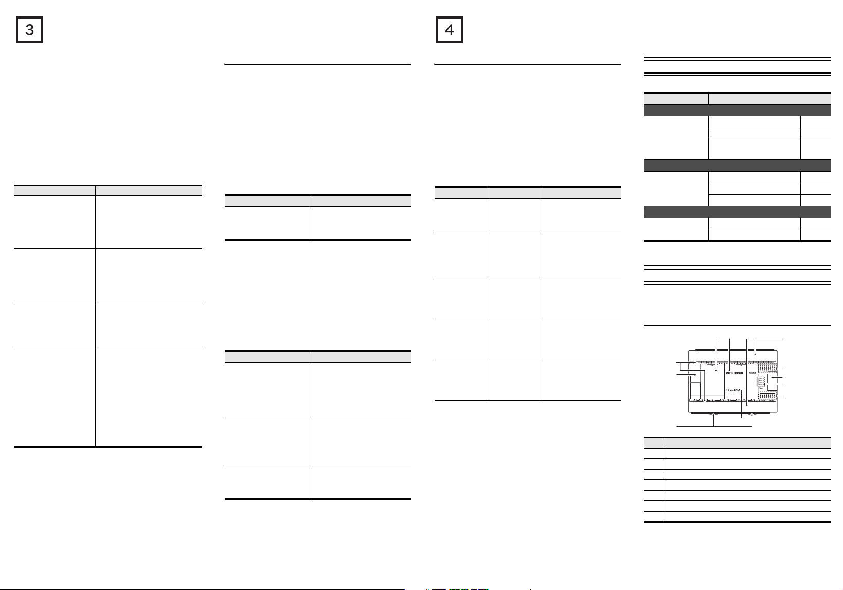
1.1 Part names
[3]
[4]
[2]
[1]
[11]
[10]
No. Name
[1] Peripheral device connecting connector cover
[2] Terminal names
[3] Top cover(S) (40points, 60points type only)
[4] Top cover
[5] Terminal block covers
[6] Input display LEDs (red)
[7] Extension device connecting connector cover
[5]
[6]
[7]
[8]
[9]
No. Name
Operation status display LEDs
POW Green On while power is on the PLC.
RUN Green On while the PLC is running.
[8]
ERR
ALM Red
Red Flashing when a program error occurs.
Red Lights when a CPU error occurs.
Lights when the battery voltage drops.
(When the optional battery is used)
[9] Output display LEDs (red)
[10] Model name (abbreviation)
[11] DIN rail mounting hooks
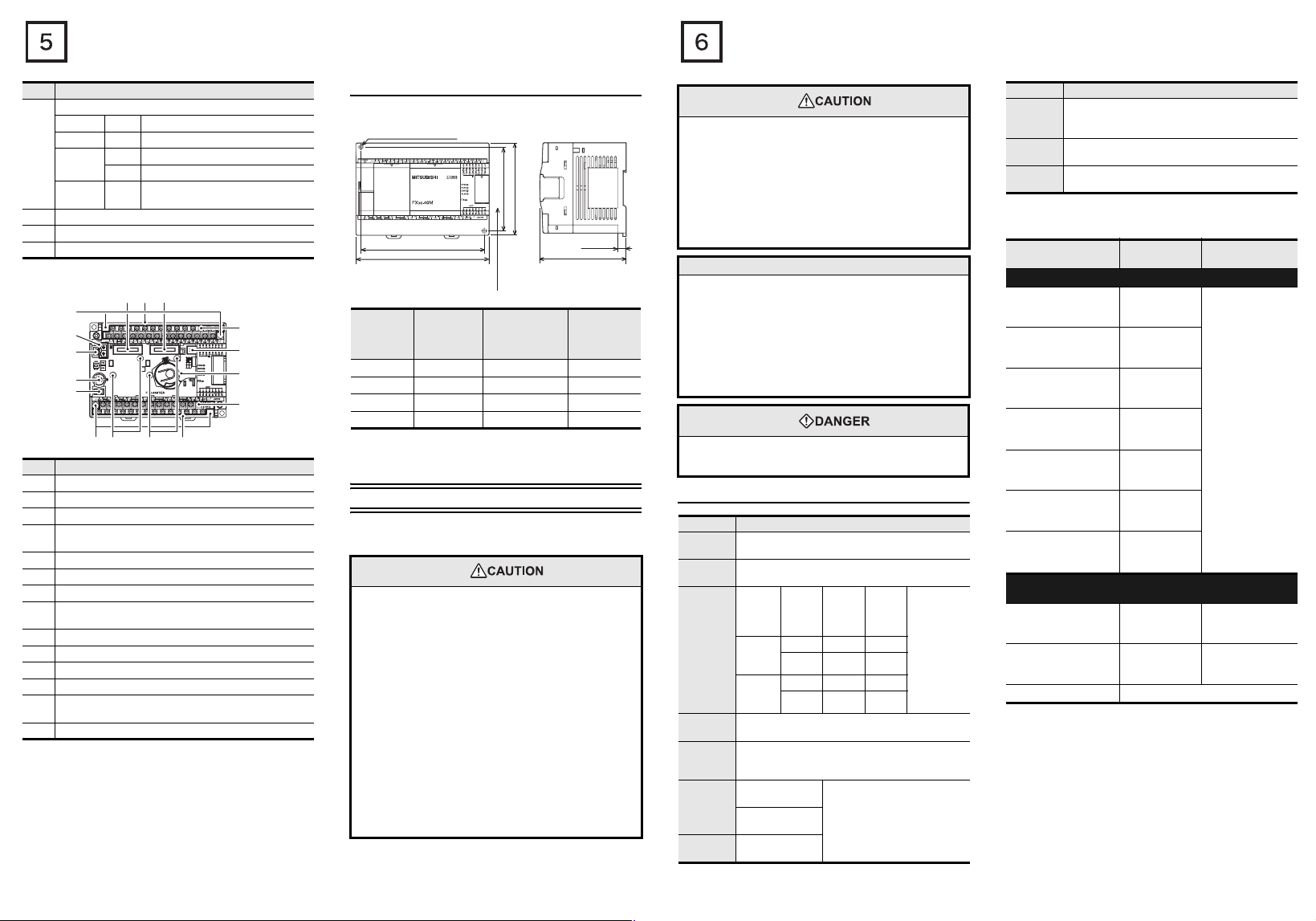
With terminal cover open
[6] [7] [8]
[5]
[4]
[3]
[2]
[1]
[5]
[14] [13]
[7]
No. Name
[1] Peripheral device connecting connector (USB)
[2] Peripheral device connecting connector (RS-422)
[3] R UN/STOP switch
Variable analog potentiometers
[4]
Upper side : VR1, Lower side : VR2
[5] Terminal block mounting screws
[6] Optional equipment connector1
[7] Terminal cover (FX3G-M/ES-A is excluded)
Optional equipment connector2
[8]
(40points, 60points type only)
[9] Power supply terminal, Input (X) terminals
[10] Battery connector
[11] Battery holder
[12] Power supply terminal, Output (Y) terminals
Optional equipment connecting screw holes2
[13]
(40points, 60points type only)
[14] Optional equipment connecting screw holes1
[9]
[10]
[11]
[12]
1.2 External dimensions and weight
→ For the input/output extension units/blocks,
refer to FX3G Series User's Manual - Hardware Edition.
2-φ4.5 mounting holes
Model name
W1
W
W:
mm (inches)
82(3.23")
Mounting hole pitches
mm (inches)
Direct mounting
hole pitches
90(3.55")
W1:
Unit: mm(inches)
8(0.32")
86(3.39")
MASS (Weight)
kg (lbs)
FX3G-14M 90 (3.55”) 82 (3.23”) 0.50 (1.10lbs)
FX3G-24M 90 (3.55”) 82 (3.23”) 0.55 (1.21lbs)
3G-40M 130 (5.12”) 122 (4.81”) 0.70 (1.54lbs)
FX
FX3G-60M 175 (6.89”) 167 (6.58”) 0.85 (1.87lbs)
Installation
• 35-mm-wide DIN rail or Direct (screw) mounting (M4)
2. Installation (general specifications)
As for installation of the input/output extension units/blocks, special
adapters and expansion boards, refer to the following manual.
→ Refer to FX3G Series User's Manual - Hardware Edition.
INSTALLATION
PRECAUTIONS
• Use the product within the generic environment specifications
described in section 2.1 of this manual.
Never use the product in areas with excessive dust, oily smoke,
conductive dusts, corrosive gas (salt air, Cl2, H2S, SO2 or
NO
2), flammable gas, vibration or impacts, or exposed to high
temperature, condensation, or rain and wind.
If the product is used in such conditions, electric shock, fire,
malfunctions, deterioration or damage may occur.
•
Do not touch the conductive parts of the product directly to avoid
failure or malfunctions.
• Install the product securely using a DIN rail or mounting screws.
• Install the product on a flat surface.
If the mounting surface is rough, undue force will be applied to
the PC board, thereby causing nonconformities.
• When drilling screw holes or wiring, make sure cutting or wire
debris does not enter the ventilation slits.
Failure to do so may cause fire, equipment failures or
malfunctions.
• Be sure to remove the dust proof sheet from the PLC's
ventilation port when installation work is completed. Failure to
do so may cause fire, equipment failures or malfunctions.
INSTALLATION
PRECAUTIONS
• Connect the extension cables, peripheral device cables, input/
output cables and battery connecting cable securely to their
designated connectors.
Unsecured connection may cause malfunctions.
• Turn off the power before attaching or detaching the following
devices.
Failure to do so may cause device failures or malfunctions.
- Peripheral devices, display modules, expansion boards and
special adapters
- Extension units/blocks and the FX Series terminal block
- Battery and memory cassette
• When a dust proof sheet is supplied with an extension unit/
block, keep the sheet applied to the ventilation slits during
installation and wiring work.
:
• To prevent temperature rise, do not install the PLC on a floor, a
ceiling or a vertical surface.
Install it horizontally on a wall as shown in section 2.2.
• Keep a space of 50mm (1.97”) or more between the unit main
body and another device or structure (part A). Install the unit as
far away as possible from high-voltage lines, high-voltage
devices and power equipment.
WIRING
PRECAUTIONS
• Cut off all phases of the power supply externally before
installation or wiring work in order to avoid damage to the
product or electric shock.
2.1 Generic specifications
Item Specification
Ambient
temperature
Ambient
humidity
Vibration
*1
resistance
Shock
*1
resistance
Noise
resistance
Dielectric
withstand
*2
voltage
Insulation
*2
resistance
Notes
0 to 55°C (32 to 131°F) when operating and -25 to
75°C (-13 to 167°F) when stored
5 to 95%RH (no condensation) when operating
ration
2
(m/s
)
4.9 -
9.8 -
Half
ampli-
tude
(mm)
Sweep Count
for X, Y, Z: 10
times
(80 min in
each
direction)
*2
and
Accele-
Fre-
quency
(Hz)
When
10 to 57 - 0.035
installed
57 to 150
on DIN rail
When
10 to 57 - 0.075
installed
57 to 150
directly
147m/s2 Acceleration, Action time: 11ms, 3 times by
half-sine pulse in each direction X, Y, and Z
By noise simulator at noise voltage of 1,000Vp-p,
noise width of 1μs, rise time of 1ns and period of 30 to
100Hz
1.5kV AC for one
minute
500V AC for one
minute
5MΩ or more by
500V DC megger
Between each terminals
ground terminal
Item Specification
Class D grounding (grounding resistance: 100Ω or
Grounding
Working
atmosphere
Working
altitude
less) <Common grounding with a heavy electrical
system is not allowed.>
Free from corrosive or flammable gas and excessive
conductive dusts
*4
<2000m
*3
*1 The criterion is shown in IEC61131-2.
*2 Dielectric withstand voltage and insulation resistance are
shown in the following table.
Terminal
Dielectric
strength
Insulation
resistance
Main units, Input/output extension units/blocks
Between power supply
terminal (AC power) and
ground terminal
Between power supply
terminal (DC power) and
ground terminal
Between input terminal
(24V DC) and ground
terminal
Between input terminal
(100V AC) and ground
*5
terminal
Between output terminal
(relay) and ground
terminal
Between output terminal
(transistor) and ground
terminal
Between output terminal
(triac) and ground
*5
terminal
Expansion boards, Special function adapters, Special function
blocks
Between terminal of
expansion board and
ground terminal
Between terminal of
special adapter and
ground terminal
1.5 kV AC for
one minute
500V AC for
one minute
500V AC for
one minute
1.5 kV AC for
one minute
1.5 kV AC for
one minute
500V AC for
one minute
1.5 kV AC for
one minute
5MΩ or more by
500V DC megger
Not allowed Not allowed
500V AC for
1min
5MΩ or more by
500V DC megger
Special function block Each manual
For dielectric with stand voltage test and insulation resistance test of
each product, refer to the following manual.
→ Refer to FX
3G Series User's Manual - Hardware Edition.
*3 For common grounding, refer to section 3.3.
*4 The PLC cannot be used at a pressure higher than the
atmospheric pressure to avoid damage.
*5 Input/output extension units/blocks only
 Loading...