

Page 1
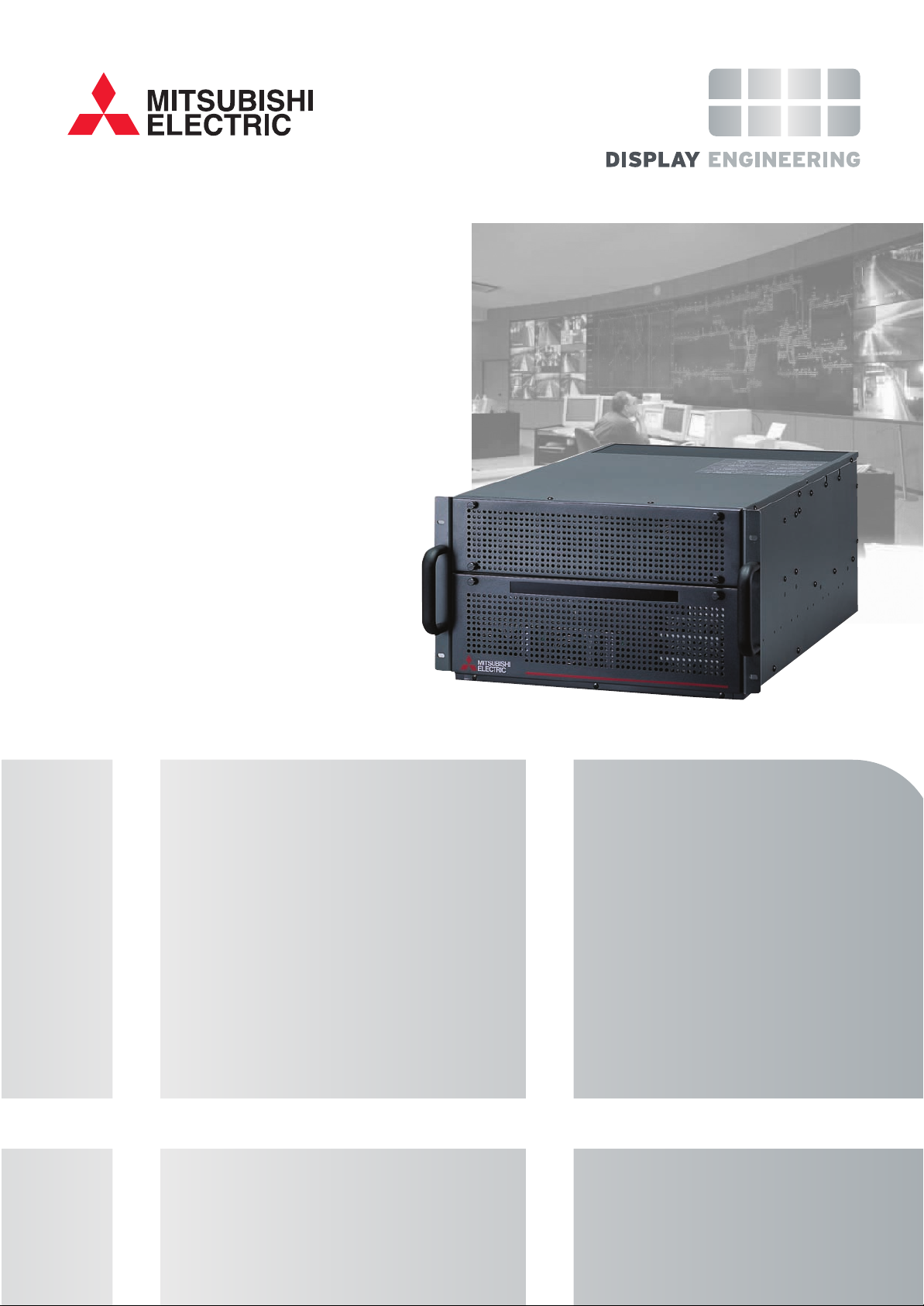
High performance display
wall processor for control
rooms and large scale
visualisation systems
• Up to 64 output channels per system
• Up to 128 freely moveable video inputs per system
• Up to 62 channels DVI / VGA inputs
• Redundant power supplies, fans and
RAID redundant disk controller
• Multiple client control stations
• Multi mouse cursor application control
VC-X3000 DISPLAY WALL PROCESSOR
The VC-X3000 display wall processor puts all of your
data and video on the display wall just the way you want
to see it. With great flexibility and ease of use, the
system is highly reliable with redundant power supplies,
fans and RAID disks. The VC-X3000 also manages the
display wall itself, monitoring and controlling
brightness, lamp changers, power on / off and key
operating parameters. The remote client D-Wall
software allows multiple operators to create and select
layouts and configure display windows and multi mouse
cursor support allows users to interact with the
applications displayed on the wall.
Page 2
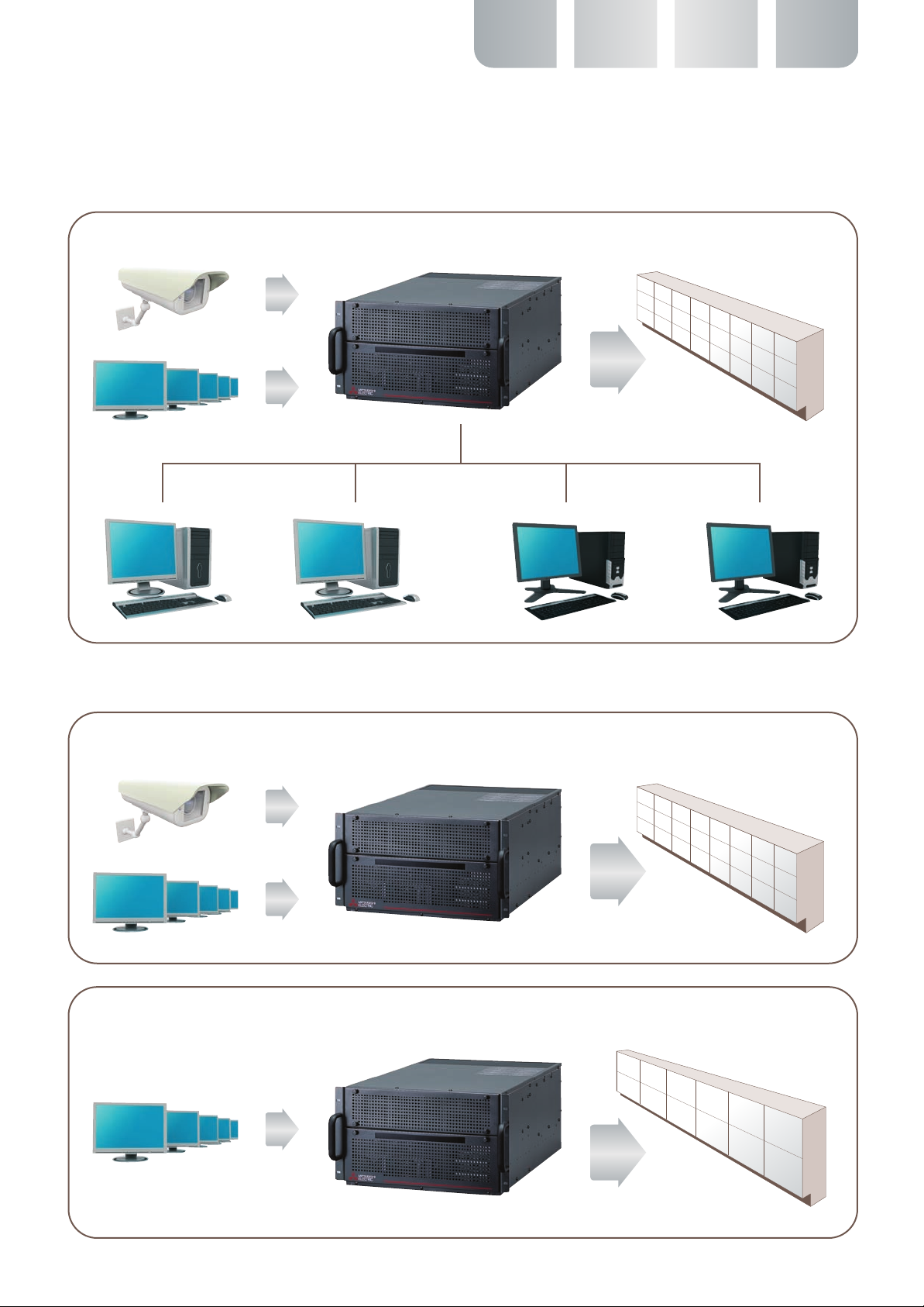
Without adding an expansion chassis, the VC-X3000 processor can provide 24 outputs, 48 video inputs, 12 DVI /
VGA inputs and unlimited network inputs – all in one unit. One or two VC-EX3000 expansion chassis may be added
to provide 64 output channels and 128 video inputs and / or 62 DVI / VGA capture channels.
12 DVI / VGA inputs and 48 video inputs displayed on 24 outputs
48 video inputs
24 outputs
12 DVI / VGA inputs
Display wall control stationsNetwork inputs
Alternative configurations for VC-X3000 without using the VC-EX3000 expansion chassis
16 DVI / VGA inputs and 16 video inputs – with 24 outputs
16 video inputs
24 outputs
16 DVI / VGA inputs
24 DVI / VGA inputs and 12 outputs
24 DVI / VGA inputs
12 outputs
Page 3

When 2 expansion chassis are added, the VC-X3000 system provides up to 64 outputs with 128 video inputs
and 34 DVI / VGA inputs. 128 video inputs and / or 62 DVI / VGA inputs can be configured if fewer output
cards are used.
128 video inputs
64 outputs
32 DVI / VGA inputs
This shows an example of the maximum configuration
for one system. Larger installations can be configured
as separate display wall areas, under software control,
or by assigning a quad of 4 cubes to display one
processor output. Using quads in this way, a wall of up
to 256 cubes with 4 video windows per cube (16 per
quad) can be realised.
Display wall processor and
controller
The X3000 not only processes the windows to be shown
on the display wall, it also controls the wall itself. The
D-Wall software suite allows operators and supervisors
to switch the wall on and off, adjust brightness and lamp
modes and monitor key parameters of the display wall
and of the processor. If anything needs attention the
status window explains the situation and users can be
alerted by email.
Display wall control stationsNetwork inputs
Page 4

The VC-X3000 D-Wall software suite manages all
aspects of set up, configuration, and daily use of the
display wall. Firstly the D-Wall Configure software is
used to set up the display wall system. It is installed on
the VC-X3000 and can be managed from a remote
client PC. The system integrator uses D-Wall Configure
to recognise the features of the display wall cubes in
the wall, set up the wall size and establish the default
values for the parameters that may be changed later by
the users.
Next the D-Wall Server software is installed on the
VC-X3000 to control all of the devices in the system.
Finally the D-Wall Control software is installed on the
operators’ PCs. D-Wall Control is used by the system
operators and supervisors to adjust, control and
monitor the system. Wall layouts can be created, saved
and recalled by drag and drop or by clicking an icon.
Window parameters such as brightness, borders,
cropping etc. can be managed – and windows can be
labelled and placed as required.
D-Wall Control graphically displays inputs, current
layout, stored layouts and system status information for
the processor and the display wall cubes with image
‘thumb nails’ on the windows. Daily operation is carried
out by drag and drop, mouse click and by monitoring the
status display. D-Wall Control can be hidden from view,
and set to respond to touch panel control for a really
safe and simple user interface.
D-Wall can also control the MK-3000 graphics insertion
processor, which can be used on it’s own or in
combination with the VC-X3000. A hybrid system using
both processors still presents the same unified image
to the operator – and windows are controlled in the
same way whether they are from the VC-X3000 or the
MK-3000.
Page 5

SPECIFICATIONS - VC-X3000
Chassis
CPU Dual-Core Intel® Xeon® Processor LV 1.66GHz x 2
System memory 1 GB (PC2-4200 512 MB Registered ECC DIMM x 2) Expandable up to 3 GB
Power supply Hot swap dual redundant power supply units – front access
Hard disk drive 80 GB (SATA 300) x 2 (RAID 1)
One optional HDD can be added to support RAID1+Hot Spare or RAID 5
Power supply AC 100 - 120V, 200 - 240V ±10%, 50/60 Hz ±3Hz
Power consumption 9.6A (AC 100 - 120V), 4.8A (AC200 - 240V)
Dimensions 483 mm (w) x 265 mm (h) x 678 mm (d) (excluding protrusions)
Weight 33 kg
4 Channel output board – Overlay Multi Graphic Board BX3000M-OMG
Resolution (800 x 600) to (1400 x 1050), (1920 x 1080)
Output connectors (X4) Digital : DVI-D
Analogue : DSUB
Maximum number of 6 boards / 24 channels per chassis
boards / channels 16 boards / 64 channels per system (using expansion chassis)
Video overlay windows from video 16 windows per cube, 128 windows per system. Freely movable, can be overlapped
input board
4 Channel output board – Multi Graphic Board BX3000M-MG
Resolution (800 x 600) to (1400 x 1050)
Output connectors (X4) Digital : DVI-D
Analogue : DSUB
Maximum number of boards / channels 8 boards / 32 channels per chassis
Video overlay windows from video Not available
input board
16 Channel video input board – BX3000V16
Number of inputs 32 composite or 16 YC
Number of channels / windows 16
Video standards NTSC / PAL / SECAM
Resolution 720 x 288
8 Channel video input board – BX3000V8
Number of inputs 16 BNC (8 composite or 8 S-video)
4 extra inputs (for component YPrPB or RGB up to 1080i)
Number of high quality video windows 4 windows (displaying 720 x 576 up to 1280 x 1024)
with de-interlacing, noise reduction
Number of standard quality windows 4 windows (displaying 720 x 288)
Video standards NTSC / PAL / SECAM / HD (720p / 1080i)
2 Channel DVI / VGA input board – BX3000G2-DVI
Resolution (640 x 480) to (1920 x 1080)
Input channels 2 DVI / VGA inputs per card, up to 62 per system depending on available slots
Maximum sampling rate 170 Mpixels per second 24 bits per pixel
Update rate Triple buffered. Up to 60 frames per second
Analogue RGB modes 640 x 480 to 1920 x 1080 RGBHV or RGB comp sync or sync on green
DVI modes 640 x 480 to 1600 x 1200 DVI single link
Connectors DVI-I connectors for analogue or digital connection
Page 6

VC-MK3000
The VC-X3000 display wall processor can also be used
together with the VC-MK3000 Graphics Insertion
Processor to create the ultimate hybrid system with real
time DVI / VGA capture and gen-locked synchronous
video. The remote client D-Wall software controls the
windows from both systems creating a single layout that
seamlessly merges X3000 windows and MK3000
sources. More details are available in the MK3000
brochure and the application note – VC-X3000 /
MK3000 hybrid systems.
Notes:
1. 8 of the 4 Channel output boards (BX3000M-MG) can be installed in one
chassis to give 32 outputs. This board does not support video overlay.
2. 6 of the 4 Channel output boards (BX3000M-OMG) can be installed in one
chassis to give 24 outputs. This board supports video overlay – see below
for details.
3. The two types of 4 output board (BX3000M-OMG and BX3000M-MG) cannot
be mixed in the same system. So, if video windows are required, the OMG
version must be used.
4. The 4 Channel output board (BX3000M-OMG) supports 16 video overlays for
each output (64 per board). Video inputs from the video capture board are
transferred by dedicated video bus.
5. Up to 8 of the 16 channel video capture boards (BX3000V16) can be
connected to the output boards by dedicated video bus to give 128 SD video
windows. This is subject to the limit of 15 slots per chassis and 6 output
boards per chassis. The maximum number of cards is also limited by power
and cooling considerations. Video windows are always captured and displayed
in real time. If large numbers if videos share the same video bus (so they can
be moved anywhere on the wall) image data for small windows is compressed
before transfer. Preference is given to large windows, to maintain the overall
image quality.
6. Up to 4 of the 8 channel video capture boards (BX3000V8) can be connected
to the output boards by dedicated video bus to give 32 video windows. (16 HD
and 16 SD)
7. The 8 channel video capture board (BX3000V8) has 8 video inputs, 4 SD
decoders and 4 HD decoders. In the context of video capture, SD means
composite or S-video up to 720 x 288 and HD means composite or S-video or
RGB from 720 x 576 up to 1080i. This board provides very high quality video
in 4 windows and standard video in the other 4 windows.
8. The processor is supplied with DVI or VGA output connectors as ordered.
9. DVI / VGA capture data is transferred to the output cards by PCI bus. Image
capture data is downscaled before being transferred, so that 4 DVI / VGA
capture windows displayed on one cube will each be 25% of normal size, so
that data is downscaled by a factor of 4 before transfer. This means that the
system can display 4 RGB windows on one cube with the same refresh rate as
one large RGB window. RGB windows displayed over more than one cube are
up-scaled after data transfer, so the data transfer rate does not exceed that
of one full size window.
Mitsubishi Electric Europe BV. - Benelux Office, Nijverheidsweg 23A, 3641 RP Mijdrecht, The Netherlands
Tel: +31 (0) 297 - 28 24 61 Fax: +31 (0) 297 - 28 39 36
www.MitsubishiElectric.nl Email: info@mitsubishi.nl
 Loading...