

Page 1
Air-Conditioners
SLZ-KA25, KA35, KA50VAQ3
KA25, KA35, KA50VAL3
INSTALLATION MANUAL
For safe and correct use, please read this manual and the outdoor unit installation manual thoroughly before installing the air-conditioner unit.
INSTALLATIONSHANDBUCH
Aus Sicherheitsgründen und zur richtigen Anwendung vor Installation der Klimaanlage die vorliegende Bedienungsanleitung und das Installationshandbuch gründlich durchlesen.
MANUEL D’INSTALLATION
Avant d’installer le climatiseur, lire attentivement ce manuel, ainsi que le manuel d’installation de l’appareil extérieur
pour une utilisation sûre et correct.
INSTALLATIEHANDLEIDING
Lees deze handleiding en de installatiehandleiding van het buitenapparaat zorgvuldig door voordat u met het installeren van de airconditioner begint.
MANUAL DE INSTALACIÓN
Para un uso seguro y correcto, lea detalladamente este manual de instalación antes de montar la unidad de aire
acondicionado.
MANUALE DI INSTALLAZIONE
Per un uso sicuro e corretto, prima di installare il condizionatore d’aria leggere attentamente il presente manuale ed
il manuale d’installazione dell’unità esterna.
EΓΧEIPIΔIO OΔHΓIΩN EΓKATAΣTAΣHΣ
Για σωστή και ασφαλή χρήση, διαβάστε προσεκτικά αυτό το εγχειρίδιο, καθώς και το εγχειρίδιο εγκατάστασης της
εξωτερικής μονάδας, πριν από την εγκατάσταση της μονάδας κλιματιστικού.
MANUAL DE INSTALAÇÃO
Para uma utilização segura e correcta, leia atentamente este manual e o manual de instalação da unidade exterior
antes de instalar o aparelho de ar condicionado.
INSTALLATIONSMANUAL
Läs bruksanvisningen och utomhusenhetens installationshandbok noga innan luftkonditioneringen installeras så att
den används på ett säkert och korrekt sätt.
MONTAJ ELKİTABI
Emniyetli ve doğru kullanım için, klima cihazını monte etmeden önce bu kılavuzu ve dış ünite montaj kılavuzunu
tamamıyla okuyun.
РУКОВОДСТВО ПО УСТАНОВКЕ
Для обеспечения безопасной и надлежащей эксплуатации внимательно прочтите данное руководство и руководство по установке наружного прибора перед установкой кондиционера.
FOR INSTALLER
FÜR INSTALLATEURE
POUR L’INSTALLATEUR
VOOR DE INSTALLATEUR
PARA EL INSTALADOR
PER L’INSTALLATORE
ΓΙΑ ΑΥΤΟΝ ΠΟΥ ΚΑΝΕΙ ΤΗΝ ΕΓΚΑΤΑΣΤΑΣΗ
PARA O INSTALADOR
FÖR INSTALLATÖREN
MONTÖR İÇİN
ДЛЯ УСТАНОВИТЕЛЯ
English
Deutsch
Français
Nederlands
Español
Italiano
Eλληνικά
Português
Svenska
Türkçe
Русский
Page 2
Contents
1. Safety precautions .....................................................................................2
2. Selecting the installation location ..............................................................2
3. Installation diagram ...................................................................................3
4. Installing the indoor unit ............................................................................3
5. Refrigerant piping work .............................................................................5
Note:
The phrase “Wired remote controller” in this installation manual refers only to the PAR-32MAA. If you need any information for the other remote controller,
please refer to either the installation manual or initial setting manual which are included in these boxes.
6. Drainage piping work .................................................................................6
7. Electrical work ...........................................................................................7
8. Installing the grille ....................................................................................10
9. Test run ....................................................................................................12
1. Safety precautions
• Be sure to read “Safety precautions” before installing the air conditioner.
• Be sure to observe the cautions specifi ed here as they include important
items related to safety.
• The indications and meanings are as follows.
Warning:
Could lead to death, serious injury, etc.
Caution:
Could lead to serious injury in particular environments when operated incorrectly.
Warning:
• Do not install it by yourself (customer).
Incomplete installation could cause injury due to fi re, electric shock, the unit
falling or leakage of water. Consult the dealer from whom you purchased the
unit or special installer.
• Install the unit securely in a place which can bear the weight of the unit.
When installed in an insuffi cient strong place, the unit could fall causing
injured.
• Use the specifi ed wires to connect the indoor and outdoor units securely and
attach the wires fi rmly to the terminal board connecting sections so the stress
of the wires is not applied to the sections.
Incomplete connecting and fi xing could cause fi re.
• Do not use intermediate connection of the power cord or the extension cord
and do not connect many devices to one AC outlet.
It could cause a fi re or an electric shock due to defective contact, defective
insulation, exceeding the permissible current, etc.
• Check that the refrigerant gas does not leak after installation has completed.
• Perform the installation securely referring to the installation manual.
Incomplete installation could cause a personal injury due to fi re, electric
shock, the unit falling or leakage of water.
• Perform electrical work according to the installation manual and be sure to
use an exclusive circuit.
If the capacity of the power circuit is insuffi cient or there is incomplete electri-
cal work, it could result in a fi re or an electric shock.
• The user should never attempt to repair the unit or transfer it to another loca-
tion.
Caution:
• Perform grounding.
Do not connect the ground wire to a gas pipe, water pipe arrester or telephone
ground wire. Defective grounding could cause an electric shock.
• Do not install the unit in a place where an infl ammable gas leaks.
If gas leaks and accumulates in the area surrounding the unit, it could cause
an explosion.
• Install a ground leakage breaker depending on the installation place (where
it is humid).
If a ground leakage breaker is not installed, it could cause an electric
shock.
• After reading this manual, be sure to keep it together with the instruction
manual in a handy place on the customer’s site.
: Indicates a part which must be grounded.
Warning:
Carefully read the labels affi xed to the main unit.
• The appliance shall be installed in accordance with national wiring regula-
tions.
• If the supply cord is damaged, it must be replaced by the manufacturer, its
service agent or similarly qualifi ed persons in order to avoid a hazard.
• Attach the electrical part cover to the indoor unit and the service panel to the
outdoor unit securely.
If the electrical part cover in the indoor unit and/or the service panel in the
outdoor unit are not attached securely, it could result in a fi re or an electric
shock due to dust, water, etc.
• Be sure to use the part provided or specifi ed parts for the installation work.
The use of defective parts could cause an injury or leakage of water due to a
fi re, an electric shock, the unit falling, etc.
• Ventilate the room if refrigerant leaks during operation.
If the refrigerant comes in contact with a fl ame, poisonous gases will be
released.
• When installing or relocating, or servicing the air conditioner, use only the
specifi ed refrigerant (R410A) to charge the refrigerant lines. Do not mix it with
any other refrigerant and do not allow air to remain in the lines.
If air is mixed with the refrigerant, then it can be the cause of abnormal high
pressure in the refrigerant line, and may result in an explosion and other
hazards.
The use of any refrigerant other than that specifi ed for the system will cause
mechanical failure or system malfunction or unit breakdown. In the worst
case, this could lead to a serious impediment to securing product safety.
• Perform the drainage/piping work securely according to the installation
manual.
If there is a defect in the drainage/piping work, water could drop from the unit
and household goods could be wet and damaged.
• Fasten a fl are nut with a torque wrench as specifi ed in this manual.
When fastened too tight, a fl are nut may broken after a long period and cause
a leakage of refrigerant.
• If the unit is run for long hours when the air above the ceiling is at high tem-
perature/high humidity (dew point above 26 ºC), dew condensation may be
produced in the indoor unit or the ceiling materials. When operating the units
in this condition, add insulation material (10-20 mm) to the entire surface of
the unit and ceiling materials to avoid dew condensation.
2. Selecting the installation location
2.1. Indoor unit
• Where airfl ow is not blocked.
• Where cool air spreads over the entire room.
• Where it is not exposed to direct sunshine.
• At a distance 1 m or more away from your TV and radio (to prevent picture from
being distorted or noise from being generated).
2.2. Wireless remote controller mounting
(For SLZ-KA·VAL3)
• Place of mounting
• Where it is easy to operate and easily visible.
• Where children can not touch.
• Mounting
Select a position about 1.2 m above the fl oor, check that signals from the remote
controller are surely received by the indoor unit from that position (‘beep’ or ‘beepbeep’ receiving tone sounds). After that, attach remote controller holder to a pillar
or wall and set the wireless remote controller.
2
• In a place as far away as possible from fl uorescent and incandescent lights (so the
infrared remote control can operate the air conditioner normally).
• Where the air fi lter can be removed and replaced easily.
Warning:
Mount the indoor unit into a ceiling strong enough to withstand the weight of
the unit.
In rooms where inverter type fl uorescent lamps are used, the signal from the
wireless remote controller may not be received.
Page 3
3. Installation diagram
23520
650
650
Fig. 3-1
4. Installing the indoor unit
1
3
6
0
7
A
2
4
8
(mm)
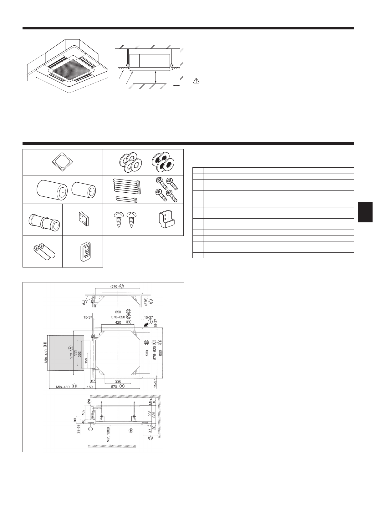
3.1. Indoor unit (Fig. 3-1)
A Ceiling
B Grille
C Obstacle
D Min. 1000 mm
E Min. 500 mm (Entire periphery)
If setting the maintenance space for E, be sure to leave is a minimum of 700 mm.
Warning:
Mount the indoor unit on a ceiling strong enough to withstand the weight of
the unit.
3.2. Outdoor unit
Refer to the outdoor unit installation manual.
4.1. Check the indoor unit accessories (Fig. 4-1)
The indoor unit should be supplied with the following accessories.
Installation template 1
5
9
1
Washers (with insulation)
2
Washers (without insulation)
Pipe cover (for refrigerant piping joint)
small diameter (liquid)
3
large diameter (gas)
Band (large)
4
Band (small)
Screw with washer (M5 25) for mounting grille 4
5
Drain socket 1
6
Insulation 1
7
8 Fixing screw for 9 3.5 16 (Black) (for SLZ-KA·VAL3)
Remote controller holder (for SLZ-KA·VAL3) 1
9
Battery (AAA) (for SLZ-KA·VAL3) 2
0
Wireless remote controller (for SLZ-KA·VAL3) 1
1
Accessory name Q’ty
4
4
1
1
6
2
2
Fig. 4-1
(mm)
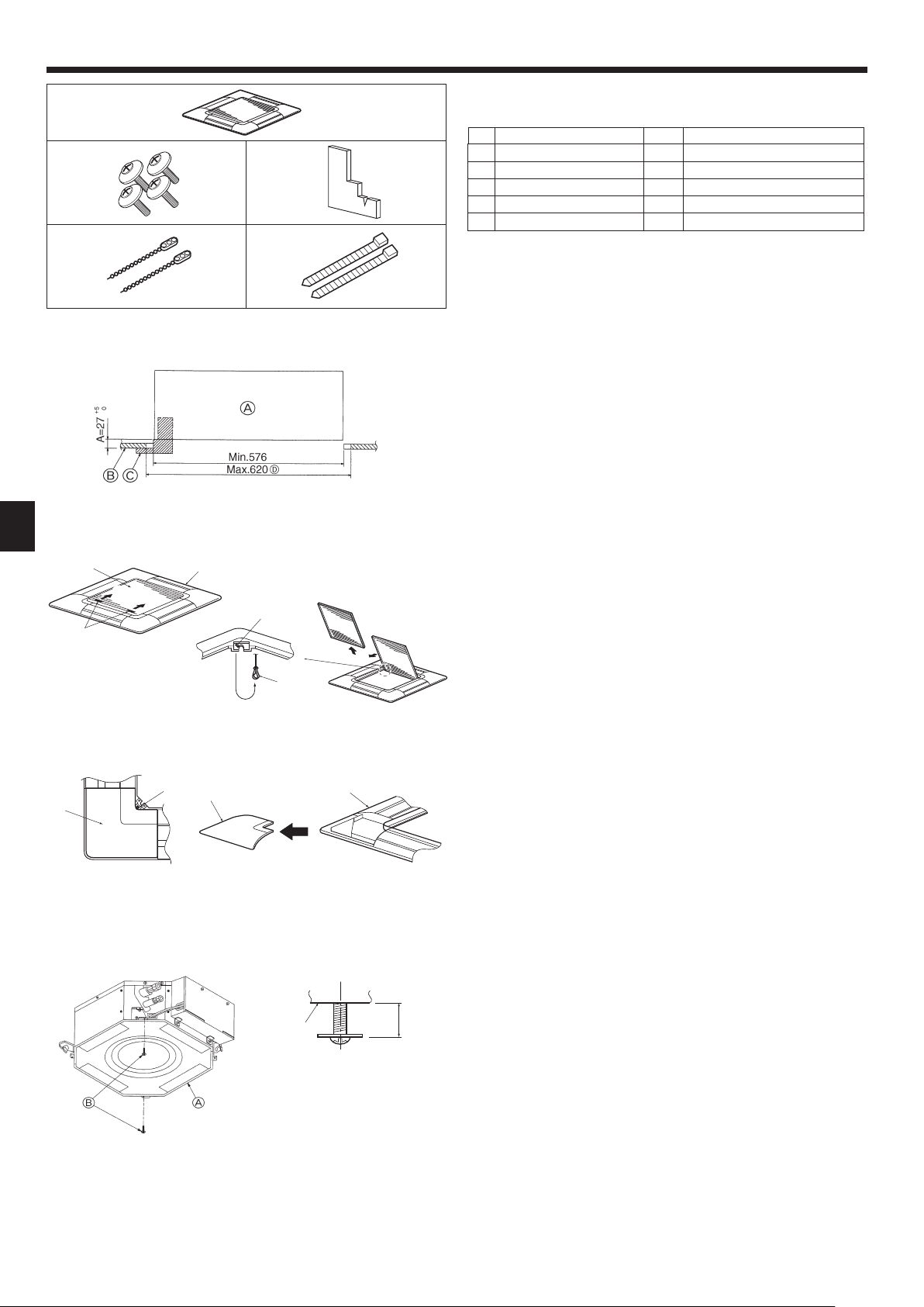
4.2. Ceiling openings and suspension bolt installation
locations (Fig. 4-2)
• Using the installation template (top of the package) and the gauge (supplied as an
accessory with the grille), make an opening in the ceiling so that the main unit can
be installed as shown in the diagram. (The method for using the template and the
gauge are shown.)
* Before using, check the dimensions of template and gauge, because they
change due to fl uctuations of temperature and humidity.
* The dimensions of ceiling opening can be regulated within the range shown in
following diagram; so center the main unit against the opening of ceiling, ensuring that the respective opposite sides on all sides of the clearance between
them becomes identical.
• Use M10 (3/8") suspension bolts.
* Suspension bolts are to be procured at the fi eld.
• Install securely, ensuring that there is no clearance between the ceiling panel &
grille, and between the main unit & grille.
A Outer side of main unit
B Bolt pitch
C Ceiling opening
D Outer side of Grille
E Grille
F Ceiling
* Note that the space between ceiling panel of the unit and ceiling slab, etc., must be 10 to 15
mm to be left.
* Leave the maintenance space at the electric component box end.
G Min. 500 mm (Entire periphery)
If setting the maintenance space for G, be
sure to leave is a minimum of 700 mm.
H Maintenance space
I Fresh air intake
J Angle
K Electric component box
Fig. 4-2
3
Page 4
4. Installing the indoor unit
4.3. Installation of duct (in case of fresh air intake)
(Fig. 4-3)
Linkage of duct fan and air conditioner
ln case that a duct fan is used, be sure to make it linked with the air conditioner
when outside air is taken.
208
Do not run the duct fan only. It can cause dew drop.
Making a duct fl ange (prepared locally)
• The shape of duct fl ange shown left is recommended.
Installation of duct fl ange
0
• Cut out the cutout hole. Do not knock it out.
+5
27
• Install a duct fl ange to the cutout hole of the indoor unit with three 4 10 tapping
Installation of duct (should be prepared locally)
• Prepare a duct of which inner diameter fi ts into the outer diameter of the duct
• In case that the environment above the ceiling is high temperature and high humidity,
120
(mm)
92
AC
120
30
75
120
100
15
20
120
70
25
100
Fig. 4-3
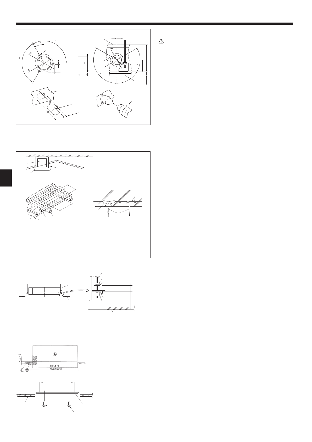
4.4. Suspension structure (Give site of suspension
• The ceiling work differs according to the construction of the building. Building con-
(1) Extent of ceiling removal: The ceiling must be kept completely horizontal and the
(2) Cut and remove the ceiling foundation.
(3) Reinforce the ends of the ceiling foundation where it has been cut and add ceiling
(4) When installing the unit on a slanting ceiling, interlock a pillow between the ceiling
1 Wooden structures
• Use tie beams (single-story houses) or second fl oor beams (two story houses) as
• Wooden beams for suspending air conditioners must be sturdy and their sides must
2 Ferroconcrete structures
Secure the suspension bolts using the method shown, or use steel or wooden hangers, etc. to install the suspension bolts.
4.5. Unit suspension procedures (Fig. 4-5)
Suspend the main unit as shown in the diagram.
1. In advance, set the parts onto the suspension bolts in the order of the washers
• Fit the washer with cushion so that the insulation faces downward.
• In case of using upper washers to suspend the main unit, the lower washers (with
2. Lift the unit to the proper height of the suspension bolts to insert the mounting
3. When the main unit can not be aligned against the mounting hole on the ceiling,
• Make sure that step A is performed within 27-32 mm. Damage could result by
4.6. Confi rming the position of main unit and tightening
• Using the gauge attached to the grille, ensure that the bottom of the main unit is
• Confi rm that the main unit is horizontally levelled, using a level or a vinyl tube fi lled
• After checking the position of the main unit, tighten the nuts of the suspension bolts
• The installation template can be used as a protective sheet to prevent dust from
* As for the details of fi tting, refer to the instructions given on the Installation template.
1
*B
D Ceiling
E Rafter
F Beam
G Roof beam
A Suspension bolt (Procure locally)
B Ceiling
C Nut (Procure locally)
D Washer (with insulation) (Accessory)
A Unit
B Grille
C Pillow
*B
2
H Use inserts rated at 100-150 kg
each (procure locally)
I Suspension bolts M10 (3/8") (procure
locally)
J Steel reinforcing rod
*B: Suspension bolt pitch (see Fig. 4-2 B for details)
Fig. 4-4
+5
0
27
Min. 30
93
E Mounting plate
F Washer (without insulation) (Accessory)
G Check using the Installation gauge
Fig. 4-5
A Main unit
B Ceiling
C Gauge (Grille accessory)
D Ceiling opening dimensions
Fig. 4-6
A Main unit
B Ceiling
C Installation template (Accessory)
D Screw with washer (Accessory)
Fig. 4-7
Caution:
screws which should be prepared locally.
fl ange.
wrap the duct in a heat insulate to avoid causing dew drop on the wall.
A Duct fl ange recommended shape
(Thickness:0.8 or more)
B 3-ø5 hole
C Detail drawing of fresh air intake
D Indoor unit
E Ceiling surface
F 3-ø2.8 Burring hole
G ø73.4 cutout hole
H Duct fl ange (Prepared locally)
I 4 10 Tapping screw (Prepared locally)
J Duct
strong structure) (Fig. 4-4)
structors and interior decorators should be consulted for details.
ceiling foundation (framework: wooden slats and slat holders) must be reinforced
in order to protect the ceiling from vibration.
foundation for securing the ends of the ceiling board.
and the grille and set so that the unit is installed horizontally.
reinforcing members.
be at least 6 cm long if the beams are separated by not more than 90 cm and their
sides must be at least 9 cm long if the beams are separated by as much as 180
cm. The size of the suspension bolts should be ø10 (3/8
"). (The bolts do not come
with the unit.)
(with insulation), washers (without insulation) and nuts (double).
insulation) and nuts (double) are to be set later.
plate between washers and then fasten it securely.
it is adjustable owing to a slot provided on the mounting plate. (Fig. 4-6)
failing to adhere to this range.
the suspension bolts (Fig. 4-7)
properly aligned with the opening of the ceiling. Be sure to confi rm this, otherwise
condensation may form and drip due to air leakage etc.
with water.
securely to fasten the main unit.
entering the main unit when the grilles are left unattached for a while or when the
ceiling materials are to be lined after installation of the unit is fi nished.
4
Page 5
5. Refrigerant piping work
SLZ-KA25, KA35: ø9.52
SLZ-KA50: ø12.7
/
/
/
0
1
A Indoor unit
ø6.35
B Outdoor unit
Fig. 5-1
a Copper tubes
90
21034
b Good
c No good
d Tilted
e Uneven
f Burred
5.1. Refrigerant pipe (Fig. 5-1)
Piping preparation
• Refrigerant pipes of 3, 5, 7, 10 and 15 m are available as optional items.
(1) Table below shows the specifi cations of pipes commercially available.
Model Pipe
SLZ-KA25
SLZ-KA35
SLZ-KA50
(2) Ensure that the 2 refrigerant pipes are well insulated to prevent condensation.
(3) Refrigerant pipe bending radius must be 100 mm or more.
Using careful insulation of specifi ed thickness. Excessive thickness prevents
storage behind the indoor unit and smaller thickness causes dew drippage.
For liquid 6.35 1/4 0.8 mm 8 mm
For gas 9.52 3/8 0.8 mm 8 mm
For liquid 6.35 1/4 0.8 mm 8 mm
For gas 9.52 3/8 0.8 mm 8 mm
For liquid 6.35 1/4 0.8 mm 8 mm
For gas 12.7 1/2 0.8 mm 8 mm
Caution:
Outside diameter
mm inch
Min. wall
thickness
Insulation
thickness
Insulation
material
Heat resist-
ing foam
plastic 0.045
specifi c
gravity
5.2. Flaring work
• Main cause of gas leakage is defect in fl aring work.
Carry out correct fl aring work in the following procedure.
5.2.1. Pipe cutting (Fig. 5-2)
• Using a pipe cutter cut the copper tube correctly.
Fig. 5-2
0
1
2
a Burr
b Copper tube/pipe
c Spare reamer
d Pipe cutter
Fig. 5-3
/
0
a Flare nut
b Copper tube
Fig. 5-4
A
3
2
0
1
a Flaring tool
b Die
c Copper tube
d Flare nut
e Yoke
5.2.2. Burrs removal (Fig. 5-3)
• Completely remove all burrs from the cut cross section of pipe/tube.
• Put the end of the copper tube/pipe to downward direction as you remove burrs in
order to avoid burrs drop in the tubing.
5.2.3. Putting nut on (Fig. 5-4)
• Remove fl are nuts attached to indoor and outdoor unit, then put them on pipe/tube
having completed burr removal.
(not possible to put them on after fl aring work)
5.2.4. Flaring work (Fig. 5-5)
• Carry out fl aring work using fl aring tool as shown at the right.
Dimension
Pipe diameter
(mm)
6.35 0 - 0.5 9.1
9.52 0 - 0.5 13.2
12.7 0 - 0.5 16.6
Firmly hold copper tube in a die in the dimension shown in the table at above.
When the tool for R410A is used
A (mm)
Clutch type
+0
B
(mm)
-0.4
Fig. 5-5
0
/
B
23456
1
7
Fig. 5-6
5.2.5. Check (Fig. 5-6)
• Compare the fl ared work with a fi gure in right side hand.
• If fl are is noted to be defective, cut off the fl ared section and do fl aring work
again.
a Smooth all around
b Inside is shining without any scratches
c Even length all around
d Too much
e Tilted
f Scratch on fl ared plane
g Cracked
h Uneven
i Bad examples
5.3. Refrigerant and drainage piping locations (Fig.5-7)
A Drain pipe
B Ceiling
C Grille
D Refrigerant pipe (liquid)
E Refrigerant pipe (gas)
F Water supply inlet
G Main unit
A
As viewed from A
Fig. 5-7
5
Page 6
5. Refrigerant piping work
,
A Refrigerant pipe and insulating material
B Pipe cover (large) (Accessory)
C Pipe cover (small) (Accessory)
D Refrigerant pipe (gas)
E Refrigerant pipe (liquid)
F Band (Accessory)
G Cross-sectional view of connection
H Refrigerant pipe
I Insulating material
J Squeeze
Fig. 5-8
(Procure locally)
5.4. Pipe connection (Fig. 5-8)
Indoor unit
1) When using commercially available copper pipes:
• Apply thin layer of refrigerant oil to pipe and joint seating surface before tightening
fl are nut.
• Use two wrenches to tighten piping connections.
• Air-purge the refrigerant piping using your own refrigerant gas (don’t air-purge the
refrigerant charged in the outdoor unit).
• Use leak detector or soapy water to check for gas leaks after connections are
completed.
• Use refrigerant piping insulation provided to insulate indoor unit connections. Insulate
carefully following shown below.
2) Heat insulation for refrigerant pipes:
1 Wrap the enclosed large-sized pipe cover around the gas pipe, making sure that
the end of the pipe cover touches the side of the unit.
2 Wrap the enclosed small-sized pipe cover around the liquid pipe, making sure that
the end of the pipe cover touches the side of the unit.
3 Secure both ends of each pipe cover with the enclosed bands. (Attach the bands
20 mm from the ends of the pipe cover.)
See that stop valve on outdoor unit is fully shut (unit is shipped with valve shut).
After all piping connections between indoor and outdoor unit have been completed,
vacuum-purge air from system through the service port for the stop valve on the
outdoor unit.
After completing procedures above, open outdoor unit stop valves stem fully. This
completes connection of refrigerant circuit between indoor and outdoor units. Stop
valve instructions are marked on outdoor unit.
• Apply a thin coat of refrigeration oil on the seat surface of pipe. (Fig. 5-9)
• For connection fi rst align the center, then tighten the fi rst 3 to 4 turns of fl are nut.
• Use tightening torque table below as a guideline for indoor unit side union joint
section, and tighten using two wrenches. Excessive tightening damages the fl are
section.
Fig. 5-9
6. Drainage piping work
1
2
Max. 20 m
1.5–2 m
Copper pipe O.D.
(mm)
Flare nut O.D.
(mm)
Tightening torque
(N·m)
ø6.35 17 14 - 18
ø9.52 22 34 - 42
ø12.7 26 49 - 61
Warning:
Be careful of fl ying fl are nut! (Internally pressurized)
Remove the fl are nut as follows:
1. Loosen the nut until you hear a hissing noise.
2. Do not remove the nut until the gas has been completely released (i.e., hiss-
ing noise stops).
3. Check that the gas has been completely released, and then remove the
nut.
6.1. Drainage piping work (Fig. 6-1)
• Use VP25 (O. D. ø32 PVC TUBE) for drain piping and provide 1/100 or more
downward slope.
• Be sure to connect the piping joints using a polyvinyl type adhesive.
• Observe the fi gure for piping work.
• Use the included drain hose to change the extraction direction.
1 Correct piping
2 Wrong piping
A Insulation (9 mm or more)
B Downward slope (1/100 or more)
Grouped piping
D O. D. ø32 PVC TUBE
E Make it as large as possible
Max. 150 mm
F Indoor unit
G Make the piping size large for grouped piping.
H Downward slope (1/100 or more)
I O. D. ø38 PVC TUBE for grouped piping.
(9 mm or more insulation)
J Up to 500 mm
C Support metal
K Air bleeder
L Raised
M Odor trap
Fig. 6-1
6
Page 7
6. Drainage piping work
30 30
11
7. Electrical work
For Power supply
30
Fig. 6-2
S3
S2S1
A Indoor unit
B Outdoor unit
C Wired remote controller
D Wired main switch/fuse
E Grounding
(mm)
,
1. Connect the drain socket (supplied with the unit) to the drain port. (Fig. 6-2)
(Affi x the tube using PVC adhesive then secure it with a band.)
2. Install a locally purchased drain pipe (PVC pipe, O.D. ø32).
(Affi x the pipe using PVC adhesive then secure it with a band.)
3. Insulate the tube and pipe. (PVC pipe, O.D. ø32 and socket)
4. Check that drain fl ows smoothly.
5. Insulate the drain port with insulating material, then secure the material with a
band. (Both insulating material and band are supplied with the unit.)
A Main unit
B Insulating material
C Band (large)
D Drain port (transparent)
E Insertion margin
F Matching
G Drain pipe (O.D. ø32 PVC TUBE)
H Insulating material (purchased locally)
I Transparent PVC pipe
J O.D. ø32 PVC TUBE (Slope 1/100 or more)
K Band (small)
L Drain socket
7.1. Precautions (Fig. 7-1)
S1
S2
S3
21
Electrical specifi cation Input capacity Main Switch/Fuse (A)
Power supply
(1 phase ~/N, 230V,
50Hz)
• The compressor will not operate unless the power supply phase connection is cor-
rect.
• Grounding protection with a no-fuse breaker (earth leakage breaker [ELB]) is usually
installed for D.
• The connection wiring between the outdoor and indoor units can be extended up
to a maximum of 50 meters, and the total extension including the crossover wiring
between rooms is a maximum of 80 m.
A switch with at least 3.5 mm contact separation in each pole shall be provided by
the air conditioner installation.
* Label each breaker according to purpose (heater, unit etc.).
SLZ-KA25 SLZ-KA35 SLZ-KA50
10 10 20
For Power
supply
Fig. 7-1
A Electric component cover
B Electric component box
C Entry for Indoor-Outdoor connecting cable
D Entry for wired remote controller cable
E Cable clamp
Fig. 7-2
F Indoor/Outdoor unit connecting terminal
G Wired remote controller terminal
(For SLZ-KA·VAQ3)
H Indoor controller
I Earth cable
7.2. Indoor unit (Fig. 7-2) (Fig. 7-3)
Work procedure
1. Remove 2 screws to detach the electric component cover.
2. Route each cable through the wiring intake into the electric component box. (Procure
power supply cable and indoor/outdoor connecting cable locally.)
3. Securely connect the power supply cable and the indoor/outdoor connecting cable
to the terminal blocks.
4. Secure the cables with clamps outside the electric component box.
5. Attach the electric component cover as it was.
• Fix power supply cable and indoor/outdoor connecting cable to electric component
box by using buffer bushing for tensile force. (PG connection or the like.)
Warning:
• Attach the electric component cover securely. If it is attached incorrectly, it
could result in a fi re, electric shock due to dust, water, etc.
• Use the specifi ed indoor/outdoor unit connecting cable to connect the indoor
and outdoor units and fi x the cable to the terminal block securely so that no
stress is applied to the connecting section of the terminal block. Incomplete
connection or fi xing of the cable could result in a fi re.
Fig. 7-3
S1S2 S3 1 2
7
Page 8
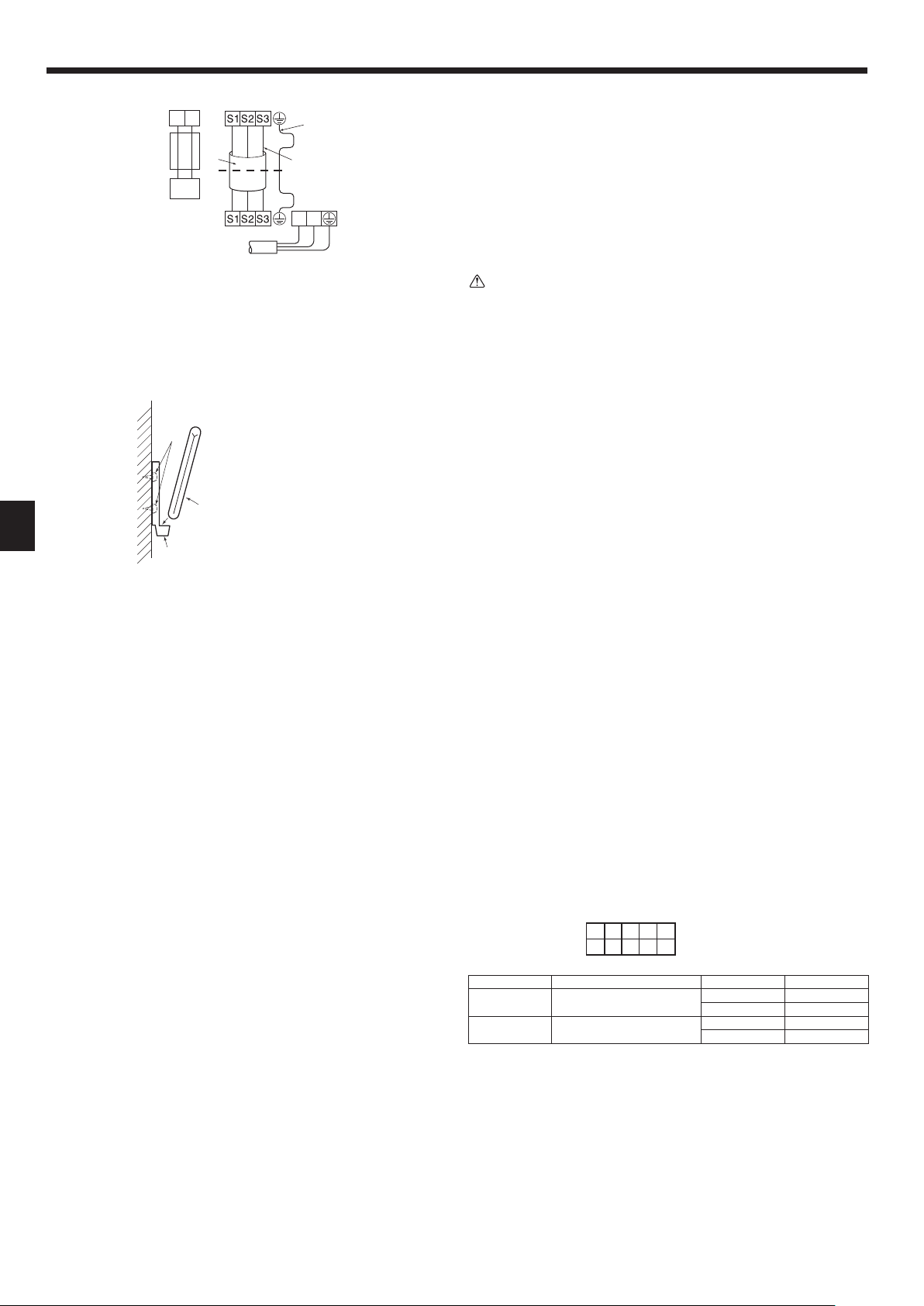
7. Electrical work
• Perform wiring as shown in the diagram to the lower left. (Procure the cable locally).
(Fig. 7-4)
Make sure to use cables of the correct polarity only.
1 Connecting cable
Cable 3-core 1.5 mm2, in conformity with Design 245 IEC 57.
2 Indoor terminal block
3 Outdoor terminal block
4 Always install an earth wire (1-core 1.5 mm2) longer than other cables
5 Remote controller cable (non-polar)
Cable 2-core 0.3 mm
The 10 m wire is attached in the remote controller accessory. Max. 500 m
6 Wired remote controller
7 Power supply cord
Caution:
• Use care not to make miswiring.
• Firmly tighten the terminal screws to prevent them from loosening.
• After tightening, pull the wires lightly to confi rm that they do not move.
• Wiring for remote controller cable shall be apart (5 cm or more) from power
source wiring so that it is not infl uenced by electric noise from power source
wiring.
2
12
Indoor terminal block
Outdoor terminal block
Power supply cord
Fig. 7-4
Earth wire (green/yellow)
Indoor/outdoor unit
connecting wire
3-core 1.5 mm
L
N
2
or more
7.3. Remote controller
A Wireless remote controller (Accessory)
B Wall
C Remote controller holder (Accessory)
D Fixing screw (Accessory)
Fig. 7-5
7.3.1. Wireless remote controller (Fig. 7-5)
1) Installation area
• Area in which the remote controller is not exposed to direct sunshine.
• Area in which there is no nearby heating source.
• Area in which the remote controller is not exposed to cold (or hot) winds.
• Area in which the remote controller can be operated easily.
• Area in which the remote controller is beyond the reach of children.
2) Installation method
1 Attach the remote controller holder to the desired location using two tapping screws.
2 Place the lower end of the controller into the holder.
• The signal can travel up to approximately 7 meters (in a straight line) within 45
degrees to both right and left of the center line of the receiver.
In addition, the signal may not be received if there is interference of light of fl uores-
cent lights or strong sunlight.
7.3.2. Wired remote controller
1) Installing procedures
Refer to the installation manual that comes with each remote controller for details.
2) Function selection of remote controller
If two remote controllers are connected, set one to “Main” and the other to “Sub”. For
setting procedures, refer to “Function selection of remote controller” in the operation
manual for the indoor unit.
7.4. Function settings
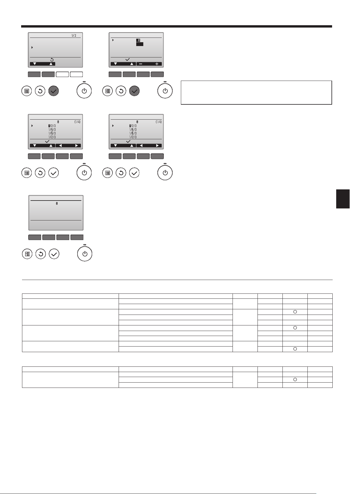
7.4.1 Function setting on the unit (Selecting the unit functions)
1) FUNCTION
Indoor controller board
This model is equipped with the FUNCTION.
(the DIP switch on the indoor controller board)
When the indoor unit is controlled with the remote controller, the operation mode, set
temperature, and the fan speed are memorized by the indoor controller board.
Factory default setting
Switch Function Switch setting Setting
SW3-1
SW3-3
Power failure automatic recovery
Fan speed when the heating
thermostat is OFF
SW3
15
2
34
ON
OFF
ON Available
OFF Not available
ON Stop
OFF Extra low
8
Page 9
7. Electrical work
Service menu
Test run
Input maintenance info.
Function setting
Check
Self check
Main menu:
Cursor
F1 F2 F3 F4
Fig. 7-6 Fig. 7-7
Function setting
Ref. address
Mode 1
Mode 2
Mode 3
Mode 4
Request:
Cursor Cursor
F1 F2 F3 F4
Grp.
Fig. 7-8 Fig. 7-9
Function setting
Ref. address
Grp.
Sending data
Function setting
Ref. address
Unit No.
Monitor:
Cursor Address
Grp./1/2/3/4/All
F1 F2 F3 F4
Function setting
Ref. address
Mode 7
Mode 8
Mode 9
Mode 10
Request:
Cursor Cursor
Unit # 1
F1 F2 F3 F4
For wired remote controller only
(Fig. 7-6)
1
• Select “Service” from the Main menu, and press the [SELECT] button.
• Select “Function settings” with the [F1] or [F2] button, and press the [SELECT]
button.
(Fig. 7-7)
2
• Set the indoor unit refrigerant addresses and unit numbers with the [F1]
through [F4] buttons, and then press the [SELECT] button to confi rm the cur-
rent setting.
<Checking the Indoor unit No.>
When the [SELECT] button is pressed, the target indoor unit will start fan
operation. If the unit is common or when running all units, all indoor units for the
selected refrigerant address will start fan operation.
(Fig. 7-8)
3
• When data collection from the indoor units is completed, the current settings
appears highlighted. Non-highlighted items indicate that no function settings
are made. Screen appearance varies depending on the “Unit No.” setting.
(Fig. 7-9)
4
• Use the [F1] or [F2] button to move the cursor to select the mode number, and
change the setting number with the [F3] or [F4] button.
(Fig. 7-10)
5
• When the settings are completed, press the [SELECT] button to send the setting data from the remote controller to the indoor units.
• When the transmission is successfully completed, the screen will return to the
Function setting screen.
Note:
• Make the above settings on Mr. Slim units as necessary.
• Table 1 summarizes the setting options for each mode number. Refer to the
indoor unit Installation Manual for the detailed information about initial settings, mode numbers, and setting numbers for the indoor units.
• Be sure to write down the settings for all functions if any of the initial settings has been changed after the completion of installation work.
F1 F2 F3 F4
Fig. 7-10
Function table
Select unit number 00
Mode Settings Mode no. Setting no.
Power failure automatic recovery *1
(AUTO RESTART FUNCTION)
Indoor temperature detecting
LOSSNAY connectivity
Power voltage 240 V
Select unit numbers 01 to 03 or all units (AL)
Mode Settings Mode no. Setting no.
Filter sign 100 Hr
*1 For this model, mode no. 1 cannot be set using the remote controller. Set this mode using DIP switch SW3-1 of the indoor controller board.
Not available
Available 2*1
01
Indoor unit operating average
Set by indoor unit’s remote controller 2
02
1*1
1
Remote controller’s internal sensor 3
Not Supported
Supported (indoor unit is not equipped with outdoor-air intake) 2
03
1
Supported (indoor unit is equipped with outdoor-air intake) 3
220 V, 230 V 2
04
1
1
2500 Hr 2
07
No fi lter sign indicator 3
Initial setting
Initial setting
Setting
Setting
9
Page 10
8. Installing the grille
1
23
45
Fig. 8-1
Fig. 8-2
8.1. Check the grille accessories (Fig. 8-1)
• The grille should be supplied with the following accessories.
Accessory name Q’ty Remark
Grille 1 650 × 650 (mm)
1
Screw with washer 4 M5 × 0.8 × 25 (mm)
2
Gauge 1
3
Fastener 2
4
Band 2
5
8.2. Preparing to attach the grille (Fig. 8-2)
• With the gauge supplied with this kit, adjust and check the positioning of the unit
relative to the ceiling. If the unit is not properly positioned in the ceiling, there may
be air leaks, condensation may form, or the up/down vanes may not operate correctly.
• Make sure that the opening in the ceiling is within the following tolerances:
576 576 - 620 620
• Make sure that step A is performed within 27-32 mm. Damage could result by failing
to adhere to this range.
A Main unit
B Ceiling
C Gauge (Accessory)
D Ceiling opening dimensions
8.2.1. Removing the intake grille (Fig. 8-3)
• Slide the levers in the direction indicated by the arrow 1 to open the intake grille.
• Unlatch the hook that secures the grille.
* Do not unlatch the hook for the intake grille.
• With the intake grille in the “open” position, remove the hinge of the intake grille
from the grille as indicated by the arrow 2.
Fig. 8-3
8.2.2. Removing the corner panel (Fig. 8-4)
Fig. 8-4
(mm)
• Remove the screw from the corner of the corner panel. Slide the corner panel as
indicated by the arrow 1 to remove the corner panel.
A Intake grille
B Grille
C Intake grille levers
D Grille hook
E Hole for the grille’s hook
F Corner panel
G Screw
8.3. Installing the grille
• Please pay attention because there is a restriction in the attachment position of the
grille.
10
Fig. 8-5
15~20
8.3.1. Preparations (Fig. 8-5)
• Install the two enclosed screws with washer in the main unit (at the corner refrigerant
pipe area and at the opposite corner) as shown in the diagram.
A Main unit
B Detailed diagram of installed screw with washer (accessory).
Page 11

8. Installing the grille
Fig. 8-6
Fig. 8-8
8.3.2. Temporary installation of the grille (Fig. 8-6)
• Align the electric component box of the main unit and the receiver of the grille, and
then temporarily secure the grille using the bell shaped holes.
* Make sure that the lead wiring of the grille does not get pinched between the
grille and the main unit.
A Main unit
B Electric component box
C Screw with washer (for temporary use)
D Screw with washer (Accessory)
E Grille
F Bell shaped hole
G Receiver (For SLZ-KA·VAL3)
8.3.3. Securing the grille (Fig. 8-7)
• Secure the grille to the main unit by tightening the previously installed two screws
(with captive washer) as well as the two remaining screws (with captive washer).
* Make sure that there are no gaps between the main unit and the grille or the
grille and the ceiling.
Caution:
When tightening the screw with captive washer 2, tighten it at a torque of 4.8
N•m or less. Never use an impact screwdriver.
• It may result in parts damage.
A Ceiling
B Main unit
C Grille
D Make sure that there are no gaps.
Fig. 8-7
8.3.4. Wire connection (Fig. 8-8)
• Be sure to connect the unit to the connector (white:10-pole/red:9-pole). Next, at-
tach the white glass tube that comes with the main unit so that the tube covers the
connector. Close the opening of the glass tube with the band.
• Make sure that there is no slack in the each lead wire at the fastener on the
grille.
A Fastener (Accessory)
B White glass tube
C Connector of the main unit
D Connector of the grille
E Band (Accessory)
F Receiver (For SLZ-KA·VAL3)
A Button
B Vane motor
C Up/down vanes
D Connector
Fig. 8-9
E Measurement standard
position of grille
F Up/down vanes
A
8.4. Locking the up/down airfl ow direction (Fig. 8-9)
The vanes of the unit can be set and locked in on up or down orientation depending
upon the environment of use.
• Set according to the preference of the customer.
The operation of the fi xed up/down vanes and all automatic controls cannot be
performed using the remote controller. In addition, the actual position of the vanes
may differ from the position indicated on the remote controller.
1 Turn off the main power switch.
Injuries and or an electrical shock may occur while the fan of the unit is rotating.
2 Disconnect the connector for the vane motor of the vent that you want to lock.
(While pressing the button, remove the connector in the direction indicated by
the arrow as shown in the diagram.) After removing the connector, insulate it with
tape.
3 To adjust the desired airfl ow direction, slowly move the up/down vanes within the
specifi ed range. (Fig. 8-10)
Specifi ed range
Up/down airfl ow
direction
A (mm) 21 25 28 30
• The vanes can be set between 21 and 30 mm.
Caution:
Do not set the up/down vanes passed the specifi ed range. Condensation could
form on and drop from the ceiling, or the unit could malfunction.
Horizontal 30° Downward 45° Downward 55° Downward 70°
Fig. 8-10
11
Page 12

8. Installing the grille
9. Test run
SLP-2ALW (For SLZ-KA·VAL3)
Fig. 8-11
8.5. Installing the intake grille (Fig. 8-11)
• Perform the procedure that is described in “8.2. Preparing to attach the grille” in
reverse order to install the intake grille and the corner panel.
A Refrigerant piping of the main unit
B Drain piping of the main unit
C Corner panel
* Installation in any position is possible.
D Position of the levers on the intake grille when sent from the factory.
* Although the clips can be installed in any of four positions.
E Receiver (For SLZ-KA·VAL3)
8.6. Check
• Make sure that there is no gap between the unit and the grille, or between the grille
and the surface of the ceiling. If there is any gap between the unit and the grille, or
between the grille and the surface of the ceiling, it may cause dew to collect.
• Make sure that the wires have been securely connected.
A Emergency operation switch (heating)
B Emergency operation switch (cooling)
C Operation lamp
SLP-2ALW (For SLZ-KA·VAL3)
Fig. 9-1
9.1. Before test run
► After installation of indoor and outdoor units, and piping and electric wiring
work, recheck that the unit is free from leaks of refrigerant, loosened connections, and incorrect polarity.
► Measure an impedance between the power supply terminal block (L, N,
on the units and the ground with a 500 V Megger and check that it is equal
to or greater than 1.0 M.
9.2. Test run
9.2.1. For wireless remote controller (Fig. 9-1)
Measure an impedance between the power supply terminal block on the outdoor unit and
the ground with a 500 V Megger and check that it is equal to or greater than 1.0 M.
• Before performing the test run, recheck for any wrong wiring.
Wrong wiring prevents normal operation or results in blown fuse disabling opera-
tion.
• Perform test run in the following procedure.
Procedure
1 Press the
If the operation lamp C blinks every 0.5 seconds, inspect the indoor/outdoor
connecting wire for miswiring.
• Check that the vanes operate properly when cool air is blown out.
2 Press it once more, and the operation stops.
3 Press the
Check that warm air blows out.
• In starting the heating operation, indoor unit fan may not operate to prevent blowing
cool air. Please wait for a few minutes until the temperature of heat exchanger rises
and warm air blows out.
4 Press it once more, and the operation stops.
Checking the remote (infrared) signal reception
Press the ON/OFF button on the remote controller and check that an electronic sound
is heard from the indoor unit. Press the ON/OFF button again to turn the air conditioner
off.
Emergency operation (when wireless remote controller is lost)
The emergency operation can be started by pressing the button B/A (cooling/heating). When the button is once pressed, the unit will start the emergency operation at
a fi xed temperature setting of 24°C in cooling mode or heating mode.
Note:
• Emergency operation does not stop automatically.
• Although the thermostat is forcibly set to on during the test run, the temperature is
set to 24°C during emergency operation and the thermostat operates according to
the room temperature.
If the indoor unit is operated with the remote controller, both the test run and the
emergency operation are released by commands from the remote controller.
Once the compressor stops, the restart preventive device operates so the compressor
will not operate for three minutes to protect the air conditioner.
button B for more than 3 seconds to start the cooling operation.
button A for more than 3 seconds to start the heating operation.
)
12
Page 13

9. Test run
9.2.2. Wired remote controller
■ Make sure to read operation manual before test run. (Especially items to secure safety)
Step 1 Turn on the power.
● Remote controller: The system will go into startup mode, and the remote controller power lamp (green) and “PLEASE WAIT” will blink. While the lamp and message
are blinking, the remote controller cannot be operated. Wait until “PLEASE WAIT” is not displayed before operating the remote controller. After the power is turned on,
“PLEASE WAIT” will be displayed for approximately 2 minutes.
● Indoor controller board: LED 1 will be lit up, LED 2 will be lit up (if the address is 0) or off (if the address is not 0), and LED 3 will blink.
● Outdoor controller board: LED 1 (green) and LED 2 (red) will be lit up. (After the startup mode of the system fi nishes, LED 2 will be turned off.) If the outdoor controller
board uses a digital display, [- ] and [ -] will be displayed alternately every second.
If the operations do not function correctly after the procedures in step 2 and thereafter are performed, the following causes should be considered and eliminated if they
are found.
(The symptoms below occur during the test run mode. “Startup” in the table means the LED display written above.)
Symptoms in test run mode
Remote Controller Display
Remote controller displays “PLEASE WAIT”,
and cannot be operated.
After power is turned on, “PLEASE WAIT” is
displayed for 3 minutes, then error code is
displayed.
No display appears even when remote controller
operation switch is turned on. (Operation lamp
does not light up.)
Display appears but soon disappears even
when remote controller is operated.
OUTDOOR BOARD LED Display
< > indicates digital display.
After “startup” is displayed, only green lights up.
<00>
After “startup” is displayed, green(once) and
red(once) blink alternately. <F1>
After “startup” is displayed, green(once) and
red(twice) blink alternately. <F3, F5, F9>
After “startup” is displayed, green(twice) and
red(once) blink alternately. <EA. Eb>
After “startup” is displayed, only green lights up.
<00>
After “startup” is displayed, only green lights up.
<00>
• After power is turned on, “PLEASE WAIT” is displayed for 2
minutes during system startup. (Normal)
• Incorrect connection of outdoor terminal block (R, S, T and S
2
S
, S3.)
• Outdoor unit’s protection devise connector is open.
• Incorrect wiring between the indoor and outdoor unit (Polarity
is wrong for S
• Remote controller transmission wire short.
• There is no outdoor unit of address 0. (Address is other than 0.)
• Remote controller transmission wire open.
• After canceling function selection, operation is not possible for
about 30 seconds. (Normal)
1
, S2, S3.)
Cause
1
,
Step 2 Switch the remote controller to “Test run”.
Select “Test run” from the Service menu, and press the [SELECT] button. (Fig. 9-2)
1
Select “Test run” from the Test run menu, and press the [SELECT] button. (Fig. 9-3)
2
The test run operation starts, and the Test run operation screen is displayed.
3
Step 3 Perform the test run and check the airfl ow temperature and auto vane.
Press the [F1] button to change the operation mode. (Fig. 9-4)
1
Cooling mode: Check that cool air blows from the unit.
Heating mode: Check that warm air blows from the unit.
Press the [SELECT] button to display the Vane operation screen, and then press
2
the [F1] and [F2] buttons to check the auto vane. (Fig. 9-5)
Press the [RETURN] button to return to the Test run operation screen.
Test run
Input maintenance info.
Function setting
Check
Self check
unem ecivreS
:unem niaM
rosruC
F1 F2 F3 F4
Fig. 9-2
RemainTest run
Pipe
Cool
Switch disp.
Mode Fan
F1 F2 F3 F4
Auto
Test run menu
Test run
Drain pump test run
Service menu:
Cursor
F1 F2 F3 F4
Fig. 9-3
Remain
Van e
F1 F2 F3 F4
Fig. 9-4
Fig. 9-5
13
Page 14

9. Test run
Step 4 Confi rm the operation of the outdoor unit fan.
The speed of the outdoor unit fan is controlled in order to control the performance of the unit. Depending on the ambient air, the fan will rotate at a slow speed and will keep
rotating at that speed unless the performance is insuffi cient. Therefore, the outdoor wind may cause the fan to stop rotating or to rotate in the opposite direction, but this is
not a problem.
Step 5 Stop the test run.
Press the [ON/OFF] button to stop the test run. (The Test run menu will appear.)
1
Note: If an error is displayed on the remote controller, see the table below.
LCD Description of malfunction LCD Description of malfunction LCD Description of malfunction
P1 Intake sensor error P9 Pipe sensor error (dual-wall pipe)
P2 Pipe sensor error (liquid pipe) PA Leakage error (refrigerant system)
Drain fl oat switch connector disconnected
P4
(CN4F)
PL Refrigerant circuit abnormal
E0 ~ E5
P5 Drain overfl ow protection operation FB Indoor controller board error
Freezing/overheating protection
P6
operation
P8 Pipe temperature error
U*, F*
(* indicates an
alphanumeric
character
excluding FB.)
Outdoor unit malfunction
Refer to the wiring diagram for the
outdoor unit.
E6 ~ EF
See the table below for the details of the LED display (LED 1, 2, and 3) on the indoor controller board.
LED1 (microcomputer power supply) Indicates whether control power is supplied. Make sure that this LED is always lit.
LED2 (remote controller power supply)
Indicates whether power is supplied to the wired remote controller. The LED is lit only for the indoor unit that is
connected to the outdoor unit that has an address of 0.
LED3 (indoor/outdoor unit communication) Indicates whether the indoor and outdoor units are communicating. Make sure that this LED is always blinking.
Communication error between the
remote controller and the indoor unit
Communication error between the
indoor unit and the outdoor unit
TOO
COOL
TOO
SELECT
FAN
TIME
AUTO COOL
VANE
DRY
HEAT
RESET
h
ON/OFF
TOO
TOO
WARM
COOL
The OPERATION INDICATOR
lamp comes on regardless of
the remote controller display.
Fig. 9-6
OPERATION INDICATOR lamp
9.3. Self-check
9.3.1. Wired remote controller
■
Refer to the installation manual that comes with each remote controller for de-
tails.
9.3.2. Wireless remote controller [SLZ-KA·VAL3 only] (Fig. 9-6)
1 Turn ON the power.
2 While pressing both the MODE SELECT button and TOO COOL button on the
remote controller at the same time, press the RESET button.
3 Release the RESET button.
4 Release the other two buttons. After three seconds, all items in the LCD are
displayed.
5 Transmit the signal of remote controller by pressing the OPERATE/STOP (ON/
OFF) button on the remote controller.
(The above procedure allows OPERATION INDICATOR lamp to indicate the
failure-mode.)
6 Transmit the signal of remote controller by pressing the OPERATE/STOP (ON/
OFF) button to stop the self-check.
14
Page 15

9. Test run
• Refer to the following tables for details on the check codes.
[Output pattern A]
Beeper sounds
OPERATION
INDICATOR
lamp fl ash
pattern
[Output pattern B]
Beeper sounds
OPERATION
INDICATOR
lamp fl ash
pattern
[Output pattern A] Errors detected by indoor unit
Wireless remote controller
Beeper sounds/OPERATION
INDICATOR lamp fl ashes
(Number of times)
[Output pattern B] Errors detected by unit other than indoor unit (outdoor unit, etc.)
Wireless remote controller
Beeper sounds/OPERATION
INDICATOR lamp fl ashes
(Number of times)
*1 If the beeper does not sound again after the initial two beeps to confi rm the self-check start signal was received and the OPERATION INDICATOR lamp does not come
on, there are no error records.
*2 If the beeper sounds three times continuously “beep, beep, beep (0.4 + 0.4 + 0.4 sec.)” after the initial two beeps to confi rm the self-check start signal was received, the
specifi ed refrigerant address is incorrect.
Beep Beep Beep Beep Beep Beep Beep
1st2nd3
Off
Self-check
starts
(Start signal
received)
Self-check
starts
(Start signal
received)
Approx. 2.5 sec.On0.5 sec.On0.5 sec.On0.5 sec.
Number of fl ashes/beeps in pattern indicates the check
code in the following table (i.e., n=5 for “P5”)
Beep Beep Beep Beep Beep Beep Beep
Off
Approx. 2.5 sec.OnApprox. 3 sec.On0.5 sec.On0.5 sec.On0.5 sec.
rd
Number of fl ashes/beeps in pattern indicates the check
code in the following table (i.e., n=5 for “U2”)
th
n
On
0.5 sec.
1st2nd3
nd
1st2
Off
Approx. 2.5 sec.On0.5 sec.On0.5 sec.
Number of fl ashes/beeps in pattern indicates
the check code in the following table
rd
th
n
On
0.5 sec.
Approx. 2.5 sec.OnApprox. 3 sec.On0.5 sec.On0.5 sec.
· · · Repeated
Off
st
1
Number of fl ashes/beeps in pattern indicates
the check code in the following table
Wired remote
controller
Symptom Remark
Check code
1 P1 Intake sensor error
2
P2 Pipe (TH2) sensor error
P9 Pipe (TH5) sensor error
3 E6, E7 Indoor/outdoor unit communication error
4 P4 Drain sensor error
5
P5 Drain pump error
PA Forced compressor error
6 P6 Freezing/Overheating safeguard operation
7 EE Communication error between indoor and outdoor units
8 P8 Pipe temperature error
9 E4 Remote controller signal receiving error
10 — —
11 — —
12 Fb Indoor unit control system error (memory error, etc.)
14
PL Refrigerant circuit abnormal
Wired remote
controller
Symptom Remark
Check code
1 E9 Indoor/outdoor unit communication error (Transmitting error) (Outdoor unit)
2 UP Compressor overcurrent interruption
3 U3, U4 Open/short of outdoor unit thermistors
4 UF Compressor overcurrent interruption (When compressor locked)
5 U2 Abnormal high discharging temperature/49C worked/insuffi cient refrigerant
6 U1, Ud Abnormal high pressure (63H worked)/Overheating safeguard operation
7 U5 Abnormal temperature of heat sink
8 U8 Outdoor unit fan safeguard stop
For details, check the LED display
of the outdoor controller board.
9 U6 Compressor overcurrent interruption/Abnormal of power module
10 U7 Abnormality of super heat due to low discharge temperature
11 U9, UH
Abnormality such as overvoltage or voltage shortage and abnormal synchronous
signal to main circuit/Current sensor error
12 — —
13 — —
14 Others Other errors (Refer to the technical manual for the outdoor unit.)
nd
· · · Repeated
2
15
Page 16

9. Test run
• On wireless remote controller
The continuous buzzer sounds from receiving section of indoor unit.
Blink of operation lamp
• On wired remote controller
Check code displayed in the LCD.
• If the unit cannot be operated properly after the above test run has been performed, refer to the following table to remove the cause.
Symptom
Wired remote controller
PLEASE WAIT
PLEASE WAIT Error code
Display messages do not appear even
when operation switch is turned ON
(operation lamp does not light up).
On the wireless remote controller with condition above, following phenomena takes place.
• No signals from the remote controller are accepted.
• OPE lamp is blinking.
• The buzzer makes a short piping sound.
Note:
Operation is not possible for about 30 seconds after cancellation of function selection. (Correct operation)
For description of each LED (LED1, 2, 3) provided on the indoor controller, refer to the following table.
LED1 (power for microcomputer) Indicates whether control power is supplied. Make sure that this LED is always lit.
LED2 (power for wired remote controller) Indicates whether power is supplied to the wired remote controller.
LED3 (communication between indoor and outdoor units) Indicates state of communication between the indoor and outdoor units. Make sure that this LED is
For about 2 minutes
following power-on
After about 2 minutes has expired
following power-on
• For about 2 minutes following power-on, operation of the
remote controller is not possible due to system start-up.
(Correct operation)
• Connector for the outdoor unit’s protection device is not
connected.
• Reverse or open phase wiring for the outdoor unit’s power
terminal block
• Incorrect wiring between indoor and outdoor units (incorrect polarity of S1, S2, S3)
• Remote controller wire short
always blinking.
Cause
SLP-2ALW (For SLZ-KA·VAL3)
Fig. 9-7
9.4. Check drainage
9.4.1. For wireless remote controller (Fig. 9-7)
• During the test run, ensure the water is being properly drained out and that no water
is leaking from joints.
• Always check this during installation even if the unit is not required to provide cooling/drying at that time.
• Similarly, check the drainage before fi nishing ceiling installation in a new premis-
es.
(1) Remove the cover of the water supply inlet and add about 1000 cc of water using
a water supply pump etc. During this process, be careful not to spray water into
the drain pump mechanism.
(2) Switching on emergency operation switch (cooling) on the grille.
(3) Confi rm that water is being drained out through the drainage outlet.
(4) After checking the drainage, ensure that the cover is replaced and the power
supply is isolated.
(5) After confi rming the drainage system is functioning, replace the drain plug.
A Insert the pump end 3 to 5 cm
B Cover of water supply inlet
C About 1000 cc
9.4.2. For wired remote controller
(1) Remove the cover of the water supply inlet and add about 1000 cc of water using
a water supply pump etc. During this process, be careful not to spray water into
the drain pump mechanism.
(2) Confi rm that water is being drained out through the drainage outlet, after switching
over from remote control mode to test run mode (cooling mode).
(3) After checking the drainage, ensure that the cover is replaced and the power
supply is isolated.
(4) After confi rming the drainage system is functioning, replace the drain plug.
D Water
E Drain plug
F Emergency operation switch (cooling)
16
Page 17

Содержание
1. Меры предосторожности.....................................................................152
2. Выбор места установки .......................................................................152
3. Диаграмма установки ..........................................................................153
4. Установка внутреннего прибора .........................................................153
5. Подготовка
Примечание:
В этом руководстве по использованию аппарата фраза “проводной пульт дистанционного управления” относится к пульту дистанционного
управления PAR-32 MA A.
Сведения о других пультах дистанционного управления приводятся в руководстве по установке или руководстве по начальным настройкам,
находящемся в этих коробках.
трубопровода охладителя ...............................................155
6. Дренажные трубы ................................................................................ 156
7. Электромонтажные работы ................................................................157
8. Установка вентиляционной решетки .................................................. 160
9. Выполнение испытания.......................................................................162
1. Меры предосторожности
• Обязательно прочтите раздел “Меры предосторожности” до установки
кондиционера.
• Обязательно соблюдайте меры предосторожности, изложенные ниже,
поскольку в них содержатся важные с точки зрения безопасности
положения.
• Символика, используемая в данном руководстве, имеет следующие
значения.
Предупреждение:
Невыполнение данного требования может привести к смертельному
исходу, тяжелой травме и т.д.
Осторожно:
Неправильное выполнение данной инструкции в определенных условиях
может привести к тяжелой травме.
Предупреждение:
• Самостоятельная установка данного прибора (клиентом) запрещается.
Незавершенная установка может привести к травме вследствие пожара, поражения
электрическим током, падения прибора или утечки воды. Обратитесь к специалисту
по установке или к дилеру, у которого вы приобрели данный прибор.
• Надежно устанавливайте прибор в месте, способном выдержать его вес.
Установка прибора в месте недостаточной прочности может привести к
падению прибора и получению травм.
• Используйте провода указанных параметров для надежного соединения
внутреннего и наружного приборов. Надежно закрепите провода в
секторах соединений выводного щитка, чтобы натяжение провода не
передавалось в секторы
Незавершенные соединения и крепление проводов могут привести к пожару.
• Не используйте промежуточные соединения в шнуре питания или
удлинитель шнура питания, и не подсоединяйте несколько приборов к
одной розетке переменного тока.
Это может привести к пожару или поражению электрическим током
вследствие дефекта контакта, дефекта изоляции, превышения
допустимого тока в сети и т.д.
•
Убедитесь в отсутствии утечки газа хладагента после завершения установки.
• Выполняйте установку с соблюдением правил безопасности, используя
руководство по установке в качестве справочника.
Незавершенная установка может привести к личной травме вследствие пожара,
поражения электрическим током, падения прибора или утечки воды.
• Выполняйте электромонтажные работы в соответствии с руководством
по установке и обязательно используйте отдельный контур питания.
При недостаточной мощности контура питания или в случае незавершенных
электромонтажных работ возможен пожар или поражение электрическим током.
• Запрещается самостоятельный ремонт или перемещение прибора.
Осторожно:
• Выполните заземление.
Запрещается подключать провод заземления к стопорным механизмам
газовых и водопроводных труб, а также проводу телефонного заземления.
Дефект заземления может привести к поражению электрическим током.
•
Запрещается устанавливать прибор в местах утечки воспламеняющихся газов.
При утечке и скоплении газа рядом с прибором возможен взрыв.
• Уст ановите прерыватель утечки тока на землю с учетом конкретного места
установки (во влажных местах).
Если прерыватель утечки тока на землю не установлен, возможно
поражение электрическим током.
соединений.
• После прочтения данного руководства обязательно храните его вместе
с руководством по эксплуатации в легкодоступном месте в помещении,
где данное оборудование эксплуатируется клиентом.
: Указывает, что данная часть должна быть заземлена.
Предупреждение:
Внимательно прочтите тек ст на этикетках главног о прибора.
• Уст ановк у необходимо выполнять в соответствии с действующими
правилами электробезопасности.
• Поврежденный кабель из комплекта поставки должен быть заменен в
целях безопасности производителем, сервисным агентом или лицами,
обладающими необходимой квалификацией.
• Надежно прикрепите крышку электрического компонента к внутреннему
прибору, а сервисную панель – к наружному прибору.
Если крышка электрического компонента и сервисная панель ненадежно
прикреплены соответственно к внутреннему и наружному приборам, это
может привести к пожару или поражению электрическим током вследствие
попадания пыли, воды и т.д. внутрь приборов.
• При выполнении работ по установке обязательно используйте детали,
входящие в комплект поставки, или детали, характеристики которых
приводятся
Использование дефектных деталей может привести к травме или утечке воды
вследствие пожара, поражения электрическим током, падения прибора и т.д.
•
В случае утечки охладителя во время выполнения работ проветрите комнату.
Если охладитель вступит в контакт с огнем, то при этом образуется токсичный газ.
• При монтаже или перемещении, а также при обслуживании кондиционера
используйте только указанный хладагент (R410A) для заполнения
трубопроводов хладагента. Не смешивайте его ни с каким другим
хладагентом и не допускайте наличия воздуха в трубопроводах.
Наличие воздуха в трубопроводах
результате которых может произойти взрыв или другие повреждения.
Использование любого хладагента, отличного от указанного для этой
системы, вызовет механическое повреждение, сбои в работе системы,
или выход устройства из строя. В наихудшем случае, это может послужить
серьезной преградой к обеспечению безопасной работы этого изделия.
• Надежно выполняйте соединения дренажных труб/трубных соединений
в соответствии с требованиями руководства по
В случае дефекта соединений дренажных труб/трубных соединений
возможно капание воды из прибора и повреждение имущества в помещении
вследствие намокания.
• Затягивайте конусную гайку с помощью тарированного ключа с крутящим
моментом, указанным в данном руководстве.
Слишком сильная затяжка конусной гайки может привести к поломке гайки
через некоторое время, результатом
•
Если прибор работает длительное время и выше потолка присутствует
воздух высокой температуры/высокой влажности (выше точки росы 26 °С),
во внутреннем приборе или на потолочных материалах может возникать
конденсация росы. При эксплуатации приборов в таких условиях, на
всю поверхность прибора и потолочных материалов следует добавлять
изоляционный материал (10–2 0 мм), чтобы предотвратить конденсацию росы
в данном руководстве.
может вызывать скачки давления, в
установке.
чего станет утечка хладагента.
2. Выбор места установки
.
2.1. Внутренний прибор
• Где нет преград на пути движения воздушного потока.
• Где прохладный воздух распространяется по всем уголкам помещения.
• Где прибор не подвержен воздействию прямых солнечных лучей.
• На расстоянии по меньшей мере 1 м от телевизора и радиоприемника. (во
избежание помех изображения или создания дополнительного шума).
• Как можно дальше от люминесцентных ламп
можно было использовать пульт дистанционного управления для нормальной
работы с прибором).
и ламп накаливания ( с тем, чтобы
2.2. Установка беспроводного пульта дистанционного
управления (Для SLZ-KA·VAL3)
• Место крепления
• Где им легко пользоваться, и где его хорошо видно.
• В недоступном для детей месте.
• Крепление
Выберите место на высоте около 1,2 м от уровня пола и убедитесь в том, что с этой позиции
сигналы с пульта дистанционного управления безошибочно принимаются внутренним
прибором (при приеме сигнала слышен одиночный или двукратный тональный гудок).
Затем прикрепите держатель пульта дистанционного управления к колонне или стене
и установите в него беспроводной пульт
дистанционного управления.
152
• Где можно легко снимать и устанавливать на место воздушный фильтр.
Предупреждение:
Устанавливайте внутренний прибор на потолок, достаточно прочный,
чтобы выдержать вес прибора.
В помещениях, где используются люминесцентные лампы инверторного
типа, сигналы с беспроводного пульта дистанционного управления могут
не приниматься прибором.
Page 18

3. Диаграмма установки
23520
650
650
Fig. 3-1
4. Установка внутреннего прибора
(мм)
3.1. Внутренний прибор (Fig. 3-1)
A Потолок
B Решетка
C Препятствие
D Мин. 1000 мм
E Мин. 500 мм (Весь периметр)
При необходимости обеспечить пространство для технического обслуживания в E,
оставьте не менее 700 мм.
Предупреждение:
Устанавливайте внутренний прибор на потолок, достаточно прочный,
чтобы выдержать вес прибора.
3.2. Наружный прибор
Обратитесь к руководству по установке наружного прибора.
1
2
4.1. Проверьте наличие дополнительных прина-
длежностей к внутреннему прибору (Fig. 4-1)
Внутренний прибор должен поставляться в комплекте со следующими дополнительными принадлежностями:
3
6
0
7
A
4
8
5
9
Fig. 4-1
(
мм)
Название приспособления Количество
Установочный шаблон 1
1
Прокладка (с изоляцией)
2
Прокладка (без изоляции)
Изоляция для труб (для соединения труб хладагента)
малого диаметра (жидкости)
3
большого диаметра (газа)
Лента (большая)
4
Лента (малая)
Винт с прокладкой (М5 × 25) для установки решетки 4
5
Соединительная муфта для дренажа 1
6
Изоляция 1
7
Шуруп крепления для 9 3,5 16 (черный)
8
(для SLZ-KA·VAL3)
Держатель пульта дистанционного управления
9
(для SLZ-KA·VAL3)
Батарейка (AAA) (для SLZ-KA·VAL3) 2
0
Беспроводной пульт дистанционного управления
1
(для SLZ-KA·VAL3)
4
4
1
1
6
2
2
1
1
4.2. Расположение отверстия в потолке и навесных
болтов (Fig. 4-2)
• С помощью установочного шаблона ( верх упаковки) и калибра (поставляется в
комплекте дополнительных принадлежностей к решетке) проделайте отверстие
в потолке таким образом, чтобы главный прибор можно было установить, как
показано на диаграмме. (Метод использования шаблона и калибра указан.)
* Прежде, чем использовать шаблон и калибр, проверьте их размеры, пос-
кольку они меняются
* Размеры отверстия в потолке можно регулировать в диапазоне, указанном
на схеме; поэтому расположите главный прибор напротив отверстия в
потолке, убедившись, что соответствующие противоположные стороны
на всех сторонах зазора между ними одинаковы.
• Используйте навесные болты М10 (3/8").
Мин.
Мин.
Мин.
Мин.
* Навесные болты приобретаются на месте.
• Выполните установку,
а также между главным прибором и решеткой нет зазора.
A Внешняя сторона главного прибора
B Шаг болта
C Потолочное отверстие
D Внешние стороны решетки
E Решетка
F Потолок
G Мин. 500 мм (Весь периметр)
При необходимости обеспечить про-
странство для технического обслуживания в G, оставьте не менее 700 мм.
* Заметьте, что между потолочной панелью прибора и потолочной плитой и т.д. следует
оставить расстояние от 10 до 15 мм слева.
* Оставьте пространство для технического обслуживания в конце коробки электрических
компонентов.
из-за перепадов температур и влажности.
убедившись, что между потолочной панелью и решеткой,
H Пространство для технического обслу-
живания
I Впуск свежего воздуха
J Угол
K Коробка электрических компонентов
Fig. 4-2
153
Page 19

4. Установка внутреннего прибора
AC
120
30
75
120
100
15
20
120
70
25
100
(мм)
208
92
120
0
+5
27
Fig. 4-3
A Прибор
B Решетка
C Вкладыш
1
*B
2
*B
D Потолок
E Стропило
F Балка
G Балка крыши
*B: Шаг подвесного болта (см. Fig. 4-2 B для получения подробной информации)
H Используйте вставки с рейтингом
100-150 кг каждая (приобретают-
ся на месте)
I Навесные болты М10 (3/8")
(приобретаются на месте)
J Стальной стержень для укрепле-
ния
Fig. 4-4
Мин.30
+5
0
27
Min. 30
93
A Навесной болт (Приобретается на месте)
B Потолок
C Га йка (Приобретается на месте)
D Прокладка (с изоляцией)
(Дополнительная принадлежность)
E Плита для навешивания
F Прокладка (без изоляции)
(Дополнительная принадлежность)
G Проверьте с помощью установочного калибра
Fig. 4-5
A Главный прибор
B Потолок
C Шаблон (Дополнительное
устройство с решеткой)
Мин.576
Макс.620
D Габариты потолочного
отверстия
Fig. 4-6
A Главный прибор
B Потолок
C Установочный шаблон (Допол-
нительная
D Винт с прокладкой (Дополни-
тельная принадлежность)
принадлежность)
Fig. 4-7
4.3. Установка короба (в случае использования
впуска свежего воздуха) (Fig. 4-3)
Осторожно:
Соединение канального вентилятора и кондиционера
Если используется канальный вентилятор, убедитесь, что при заборе
наружного воздуха он соединен с кондиционером.
Запрещается использовать только вентилятор. Такое использование может
привести к образованию капель росы.
Создание фланца короба (подготавливается на месте)
• Рекомендуется использовать фланец короба с формой, как показано слева.
Установка фланца короба
• Создайте вырезанное отверстие. Запрещается пробивать отверстие.
• Установите фланец короба к вырезанное отверстие внутреннего прибора с
помощью трех приобретенных на месте самонарезающих винтов 4 10.
Установка короба (подготавливается на месте)
• Подготовьте короб, внутренний диаметр которого помещается в наружный
диаметр фланца короба.
• Если выше потолка наблюдается среда с высокой температурой и высокой
влажностью, заверните короб в теплоизоляцию во избежание образования
капель росы на стене.
A Рекомендованная форма фланца
короба (Толщина: 0,8 или более)
B 3 отверстия с ø5
C Подробный чертеж впуска свежего
воздуха
D Внутренний прибор
E Поверхность потолка
F 3 отверстия со снятием заусениц ø2,8
G вырезное отверстие ø73,4
H Фланец короба (подготавливается на
месте)
I Самонарезающий винт 4 10
(подготавливается на месте)
J Короб
4.4. Подвесная конструкция (Обеспечьте прочность
на месте подвешивания) (Fig. 4-4)
• Потолочные конструкции могут быть разными, в завистмости от конструкции
здания. Следует проконсультироваться со строительной и ремонтной организацией.
(1) Снятие потолочного покрытия: Потолок должен быть абсолютно горизонтальным
и потолк (деревянные плиты и балки) следует укрепить, чтобы обеспечить защиту
потолка от вибрации.
(2) Вырежьте участок потолочной плиты и снимите его.
(3) Укрепите края потолочной плиты по местам среза и закрепите ее дополнительным
материалом по краям.
(4) При установке прибора на скошенный потолок
решеткой так, чтобы прибор можно было установить в горизонтальном положении.
1
Деревянные конструкции
установите вкладыш между потолком и
• В качестве укрепления используйте анкерные балки (одноэтажные дома) или балки
перекрытия (двухэтажные дома).
• Деревянные балки для подвешивания кондиционера должны быть прочными и их
боковые стороны должны быть длиной не менее 6 см, если балки разделяются не
более, чем 90 см; их боковые стороны должны быть длиной не менее 9 см, если
разделяются расстоянием 180 см. Размер навесных болтов должен быть ø 10 (3/8").
балки
(Болты не поставляются вместе с прибором.)
2
Железобетонные конструкции
Закрепляйте навесные болты, используя указанный метод, или используйте стальные
или деревянные подвесные крепления и т.д. для установки навесных болтов.
4.5. Порядок подвешивания прибора (Fig. 4-5)
Подвешивайте главный прибор, как указано на диаграмме.
1. Заранее установите детали на навесные болты в следующем порядке: про-
кладки (с изоляцией), прокладки (без изоляции) и гайки (двойные).
• Установите прокладу с изоляцией таким образом, чтобы изоляция была
направлена вниз.
• При использовании верхних прокладок для подвешивания главного прибора
нижние прокладки (с изоляцией)
и гайки (двойные) устанавливаются позднее.
2. Поднимите прибор на требуемую высоту до навесных болтов, чтобы вставить плиту для навешивания прибора между прокладками, а затем надежно
закрепит ее.
3. Если нельзя совместить главный прибор с отверстием для навешинавания на
потолке, регулировка производится с помощью щели, имеющейся на плите
для навешивания прибора. (Fig. 4-6)
Убедитесь в том, что операция А выполняется в пределах 27-32 мм. Несоблю-
•
дение данного предела может в результате привести к повреждениям.
4.6. Проверка расположения главного прибора и
затягивание навесных болтов (Fig. 4-7)
• С помощью калибра, прикрепленного к решеткам, убедитесь, что низ главного
прибора сориентирован должным образом по отношению к потолочному отверстию. Подтвердите это, в противном случае возможно капание конденсации
вследствие проникновения воздуха и т.д.
• Убедитесь, что главный прибор установлен строго по горизонтали: используйте
уровень или виниловую трубку, наполненную водой.
После проверки расположения главного прибора надежно затяните гайки
•
навесных болтов, чтобы закрепить главный прибор.
• Установочный шаблон можно использовать в качестве защитного кожуха для
предотвращения попадания пыли внутрь главного прибора, пока решетки не
установлены, или при отделке потолка по окончании установки прибора.
* Дополнительная информация по монтажу приводится на самом установочном
шаблоне
.
154
Page 20

5. Подготовка трубопровода охладителя
SLZ-KA25, KA35: ø9,52
SLZ-KA50: ø12,7
/
/
/
0
1
/
1
A Внутренний прибор
ø6,35
B Наружный прибор
Fig. 5-1
a Медные трубы
90
21034
b Приемлемо
c Неприемлемо
d Скошенный край
e Неровный край
f Заусеницы
Fig. 5-2
0
1
2
a Заусеницы
b Медная труба
c Дополнительная
развертка
d Труборез
Fig. 5-3
/
0
a Развальцовочная
гайка
b Медная труба
Fig. 5-4
A
3
2
0
1
a Развальцовочный
инструмент
b Обжимка
c Медная труба
d Развальцовочная
гайка
e Зажим
Fig. 5-5
B
0
23456
7
Fig. 5-6
5.1. Трубопровод охладителя (Fig. 5-1)
Подготовка трубопровода
• Трубы трубопровода охладителя длиной 3, 5, 7, 10 и 15 м доступны как
дополнительные устройства.
(1) В таблице ниже представлены технические характеристики имеющихся в
продаже труб.
Наружный
Модель Труба
Для жид-
SLZ-
KA25
SLZ-
KA35
SLZ-
KA50
(2) Обеспечьте изоляцию 2 труб для охладителя для предотвращения образо-
вания конденсации.
(3) Радиус изгиба трубы для охладителя должен быть не менее 100 мм.
Осторожно:
Используйте надлежащую изоляцию указанной толщины. Изоляция
чрезмерной толщины занимает все место позади внутреннего прибора,
изоляция меньшей толщины является причиной капания влаги.
кости
Для газа 9,52 3/8 0,8 мм 8 мм
Для жид-
кости
Для газа 9,52 3/8 0,8 мм 8 мм
Для жид-
кости
Для газа 12,7 1/2 0,8 мм 8 мм
диаметр
мм дюймы
6,35 1/4 0,8 мм 8 мм
6,35 1/4 0,8 мм 8 мм
6,35 1/4 0,8 мм 8 мм
Мин.
толщина
стены
Толщина
изоляции
Изоляционный
материал
Термоус-
тойчивый
пенопласт
с удельной
массой 0,045
5.2. Развальцовка
• Основной причиной утечки газа являются дефекты развальцовки.
Правильно выполняйте развальцовку в нижеописанной процедуре.
5.2.1. Резка труб (Fig. 5-2)
• Правильно режьте медную трубу с помощью трубореза.
5.2.2. Удаление заусениц (Fig. 5-3)
• Полностью удалите заусенцы с разрезанного поперечного сечения трубы.
• При удалении заусенцев наклоните медную трубу вниз, чтобы удаленные
заусенцы не попали внутрь трубы.
5.2.3. Насадка гаек (Fig. 5-4)
• Снимите конусные гайки, прикрепленные к внутреннему и наружному
приборам, затем насадите их на трубу после полного удаления заусенцев.
(после развальцовки насадка гаек невозможна)
5.2.4. Развальцовка (Fig. 5-5)
• Выполните развальцовку с помощью развальцовочного инструмента, как
показано ниже.
Размер
Диаметр трубы
(мм)
6,35 0 - 0,5 9,1
9,52 0 - 0,5 13,2
12,7 0 - 0,5 16,6
Твердо зажмите медную трубу в обжимке, соблюдая размер, указанный в
таблице выше.
5.2.5. Проверка (Fig. 5-6)
• Сравните результаты развальцовки с рисунком справа.
• При обнаружении дефекта на развальцовке обрежьте развальцованный
участок и выполните развальцовку снова.
a Ровный край по всему диаметру
b Блестящая внутренняя поверхность
без царапин
c Одинаковая длина по всему
диаметру
d Слишком
e Скошенный край
A (мм)
При использовании
инструмента для R410A
Тип муфты
+0
(мм)
B
-0,4
f Царапина на развальцовочной
плоскост
g Трещина
h Неровный край
i Примеры неправильного состояния
трубы
5.3. Расположение трубопроводов охладителя и
дренажа (Fig.5-7)
A Дренажная труба
B Потолок
C Решетка
D Труба для охладителя (жидкость)
E Труба для охладителя (газ)
F Впуск подачи воды
G Главный прибор
A
Вид со стороны A
Fig. 5-7
155
Page 21

5. Подготовка трубопровода охладителя
A Трубопровод охладителя и изоляционный
,
материал (приобретаются отдельно)
B Покрытие трубы (большого размера)
(Дополнительная принадлежность)
C Покрытие трубы (малого размера)
(Дополнительная принадлежность)
D Труба для охладителя (газ)
E Труба для охладителя (жидкость)
F Лента (Дополнительная принадлежность)
G Вид поперечного сечения соединения
H Труба для охладителя
I Изоляционный материал
J Зажим
Fig. 5-8
5.4. Соединение труб (Fig. 5-8)
Внутренний прибор
1) При использовании имеющихся в продаже медных труб:
• Нанесите тонкий слой охлаждающего масла на трубу и выполните соединение
посадочной поверхности до затяжки развальцовочной гайки.
• Используйте два ключа для затяжки трубных соединений.
• Выполните продувку трубопровода охладителя с помощью собственного охла-
дителя (запрещается производить продувку с помощью охладителя, которым
заправлен наружный прибор
• После выполнения соединений используйте детектор утечки газа или мыльную
воду для проверки утечек газа.
• Используйте поставляемую изоляцию трубы охладителя для изоляции соединений внутреннего прибора. Выполняйте изоляцию надлежащим образом, как
показано ниже.
2) Теплоизоляция труб охладителя:
1 Оберните покрытие трубы большого размера вокруг трубы для газа, убедив-
шись, что конец
покрытия трубы касается боковой части прибора.
2 Оберните покрытие трубы меньшего размера вокруг трубы для жидкости,
убедившись, что конец покрытия трубы касается боковой части прибора.
3 Закрепите оба конца покрытия каждой трубы с помощью прилагаемых лент.
(Устанавливайте ленты на расстоянии 20 мм от концов покрытий труб.)
Убедитесь, что стопорный клапан наружного
поставляется с закрытым клапаном). После завершения исполнения всех трубных соединений между наружным и внутренним прибором выполните вакуумную
продувку для удаления воздуха из системы через сервисный порт стопорного
клапана наружного прибора.
После завершения вышеописанных процедур полностью откройте стопорные
клапаны наружного прибора. Данное действие завершает соединение контура
охладителя между внутренним и наружным приборами. Указания по использованию стопорного клапана приведены на наружном приборе.
).
прибора полностью закрыт (прибор
Fig. 5-9
6. Дренажные трубы
Макс. 20 м
1
2
Max. 20 m
1,5–2 м
• Нанесите тонкий слой охлаждающего масла на посадочную поверхность трубы.
(Fig. 5-9)
• При подсоединении сначала выровняйте центр, затем затяните развальцовочную гайку на первые 3-4 оборота.
• Используя таблицу с крутящим моментом ниже в качестве руководства при
затягивании
муфтового соединения со стороны внутреннего прибора, затяните
гайки с помощью двух гаечных ключей. Чрезмерная затяжка может повредить
развальцованный участок.
Наружный диаметр
медной трубы (мм)
Наружный диаметр
развальцовочной гайки
(мм)
Крутящий момент
затяжки (Н м)
ø6,35 17 14 - 18
ø9,52 22 34 - 42
ø12,7 26 49 - 61
Предупреждение:
Опасайтесь срыва развальцовочной гайки (под воздействием внутреннего
давления)
Удаление развальцовочной гайки должно производиться следующим
образом:
1. Ослабьте гайку, пока не услышите шипящий звук.
2. Запрещается снимать гайку, пока не стравлен весь газ (т.е. до
прекращения шипящего звука).
3. Убедитесь, что газ полностью стравлен, после чего снимите гайку.
6.1. Дренажные трубы (Fig. 6-1)
• Используйте трубы VP25 (Трубы из ПХВ, O.D. ø32) для дренажа, при этом
Макс. 150 мм
Max. 150 mm
обеспечьте наклон 1/100 или более.
• Для соединения труб используйте клей семейства ПВ.
• Следуйте схематическому рисунку при подсоединении труб.
• Для изменения направления дренажа используйте входящий в комплект
поставки дренажный шланг.
1 Правильное соединение труб
2 Неправильное соединение труб
A Изоляция (9 мм или больше)
B Наклон вниз (1/100 или больше)
C Поддерживающий метал
K Выпуск воздуха
L Поднятие
M Ловушка запахов
Сгруппированные трубы
D Трубы из ПХВ, O.D. ø32
E Сделайте ее как можно большей
F Внутренний прибор
G Устанавливайте трубы большого разме-
ра для сгруппированных труб
H Наклон вниз (1/100 или больше)
I Трубы из ПХВ, O.D. ø38 для сгруппи-
рованных труб. (9 мм изоляция или
больше)
J До 500 мм
156
Fig. 6-1
Page 22

6. Дренажные трубы
30 30
11
30
Fig. 6-2
7. Электромонтажные работы
S1
S2
S3
S3
S2S1
A Внутренний прибор
B Наружный прибор
C Проводной пульт дистанционного управления
D Проводной главный выключатель/предохранитель
E Заземление
Для электро-
питания
Для электропитания
(мм)
,
1. Подсоедините соединительную муфту для дренажа (входит в комплект
поставки прибора) к дренажному порту. (Fig. 6-2)
(Закрепите трубу с помощью клея ПХВ, а затем с помощью ленты.)
Установите дренажные трубы (закупаются на месте). (Труб ы из ПХВ, O.D. ø32.)
2.
(Закрепите трубу с помощью клея ПХВ, а затем с помощью ленты.)
3. Оберните изоляцию вокруг труб. (Трубы из ПХВ, O.D. ø32 и гнездо)
4. Проверьте дренирование.
5. Изолируйте дренажный порт изоляционным материалом, затем закрепите
материал лентой. (Изоляция и лента входят в комплект прибора.)
A Прибор
B Изоляция
C Лента (большой)
D Дренажный порт (неподготовленный)
E Запас
F Соответствие
G Дренажная труба (Тру бы из ПХВ, O.D. ø32)
H Изоляция (приобретается на месте)
I Неподготовленная труба из ПВХ
J Труб ы из ПХВ, O.D. ø32
(Наклон 1/100 или более)
K Соединительная муфта для дренажа
(малый)
L Дренажный разъем
7.1. Меры предосторожности (Fig. 7-1)
21
Характеристики
электрооборудования
Питание
(1 фаза ~/Н, 230 В,
50 Гц)
• Компрессор не будет работать, если не соблюдена правильная последова-
тельность фаз электропитания.
• Заземляющая защита с автоматическим выключателем без плавкого предох-
ранителя (прерыватель утечки тока на землю [ELB]) обычно устанавливается
для D.
• Максимальная длина кабеля соединения наружного и
может быть увеличена до 50 метров максимум; максимальное общее удлинение, включая проводку между комнатами, составляет 80 м.
При установке кондиционера должен использоваться выключатель с зазорам
между разомкнутыми контактами не менее 3,5 мм на каждом полюсе.
* Все выключатели должны быть маркированы в соответствии с их назначением
(нагреватель, прибор и т.
Входной номинал главного выключателя/
предохранителя (A)
SLZ-KA25 SLZ-KA35 SLZ-KA50
10 10 20
внутреннего приборов
д.).
Fig. 7-1
A Крышка коробки электрических компонентов
B Коробка электрических компонентов
C Ввод кабеля для соединения внутрен-
него и наружного прибора
D Ввод кабеля проводного пульта дистан-
ционного управления
E Проводной зажим
Fig. 7-2
F Клемма для подключения кабеля соеди-
нения внутреннего и наружного прибора
G Клемма для подключения кабеля провод-
ного пульта дистанционного управления
(Для SLZ-KA·VAQ3)
H
Внутренний контроллер
I Кабель заземления
7.2. Внутренний прибор (Fig. 7-2) (Fig. 7-3)
Рабочая процедура
1. Удалите 2 винта, чтобы отсоединить крышку коробки электрических компо-
нентов.
2. Проведите все кабели через кабельные отверстия в коробку электрических
компонентов. (Кабели электропитания и соединения наружного/внутреннего
приборов приобретаются отдельно.)
3. Надежно подключите кабели электропитания и соединения наружного/внут-
реннего приборов к клеммным колодкам.
4. Закрепите кабели с помощью зажимов снаружи
понентов.
5. Установите на место крышку коробки электрических компонентов.
• Прикрепите кабель электропитания и кабель соединения внутреннего/наруж-
ного приборов к коробке электрических компонентов с помощью буферного
переходника силы натяжения. (соединение PG или аналогичное.)
Предупреждение:
• надежно закрепляйте крышку коробки электрических компонентов.
Неправильное подсоединение может привести к возникновению пожара
и поражению электрическим током из-за попадания пыли, воды и т. д.
• Используйте кабели указанных параметров для надежного соединения
внутреннего и наружного приборов. Надежно закрепите кабели в
клеммной колодке, чтобы натяжение провода не передавалось в
секторы соединений клеммной колодки. Незавершенное соединение или
ненадежная фиксация кабеля может привести к пожару.
коробки электрических ком-
Fig. 7-3
S1S2 S3 1 2
157
Page 23

7. Электромонтажные работы
ON
OFF
15
2
SW3
34
Клеммная колодка внутреннего прибора
12
Клеммная колодка наружного прибора
Шнур питания
Fig. 7-4
A Беспроводной пульт
B Стена
C Держатель пульта дистанционного
D Шуруп крепления (Дополнительная
Fig. 7-5
Провод заземления (зеленый/
желтый)
Соединительный провод
наружного/внутреннего прибора
3-жильный 1,5 мм
L
N
дистанционного управления
(Дополнительная принадлежность)
управления (Дополнительная
принадлежность)
принадлежность)
2
или больше
• Выполните подсоединение, как показано на схеме внизу слева. (Кабель при-
обретается отдельно). (Fig. 7-4)
Убедитесь, что используются кабели с правильной полярностью.
1 Соединительный кабель
3-жильный кабель 1,5 мм2, соответствующий требованиям промышленного образца
245 IEC 57.
2 Клеммная колодка внутреннего прибора
3 Клеммная колодка наружного прибора
4 Всегда устанавливайте заземляющий провод (1-жильный 1,5 мм
других кабелей
5 Кабель пульта дистанционного управления (неполярный)
2-жильный кабель 0,3 мм
Провод длиной 10 м присоединяется к дополнительному устройству пульта дистанци-
онного управления. Макс. 500 м
6 Проводной пульт дистанционного управления
7 Шнур питания
Осторожно:
• Внимательно следите за правильностью подсоединения проводов.
• Плотно затягивайте винты клеммной колодки для предотвращения их
ослабления.
• После затяжки винтов слегка потяните за провода, чтобы убедиться в
их неподвижности.
• Кабель пульта дистанционного управления должен проводиться на
определенном расстоянии (не менее 5 см) от кабеля источника питания
во избежание электрических помех,
питания.
2
создаваемых кабелем источника
2
), который длиннее
7.3. Пульт дистанционного управления
7. 3.1. Беспроводной пульт дистанционного управления (Fig. 7-5)
1) Места установки
• Места, в которых пульт дистанционного управления не подвержен воздействию
прямых солнечных лучей.
• Места, удаленные от источников тепла.
• Места, в которых пульт дистанционного управления не подвержен воздействию
холодного (или теплого) ветра.
• Места, максимально удобные для использования пульта дистанционного
управления.
• Места, в которых пульт дистанционного управления недосягаем для
2) Метод установки
1 Закрепите держатель пульта дистанционного управления в выбранном Вами
месте с помощью двух самонарезающих винтов.
2 Вставьте низ пульта в держатель.
• Сигнал передается на расстояние приблизительно в 7 м (по прямой линии) в
диапазоне в 45 градусов слева и справа от центральной оси приема сигналов
ресивером.
Кроме того, прим
ции флуоресцентного освещения или интенсивного солнечного света.
7.3.2. Проводной пульт дистанционного управления
1) Процедура установки
Подробное описание см. в руководстве по установке, прилагаемого к пульту
дистанционного управления.
2) Выбор функций пульта дистанционного управления
Если подключены два пульта дистанционного управления, настройте один как
“Main” (Главный), а другой - как “Sub” (Подчиненный). Процедуры настройки
приводятся в разделе “Выбор функций пульта дистанционного управления” в
руководстве по эксплуатации внутреннего прибора.
сигнала может не осуществляться при наличии интерферен-
детей.
158
7.4. Настройки функций
7. 4.1 Настройка функций на приборе (Выбор функций прибора)
1) ФУНКЦИЯ
Плата внутреннего контроллера
Данное изделие оснащено ФУНКЦИЕЙ ПЕРЕКЛЮЧАТЕЛЯ.
(переключатель DIP на плате внутреннего контроллера)
Когда управление внутренним прибором производится с пульта дистанционного
управления, режим работы, заданная температура и скорость вентилятора
вносятся в память платы внутреннего контроллера.
Заводская настройка по умолчанию
Переключатель
SW3-1
SW3-3
Функция
Автоматическое включение
после сбоя электропитания
Скорость вентилятора при
ОТКЛЮЧЕНИИ термореле
системы подогрева
Положение
переключателя
ON (ВКЛ.) Доступно
OFF (ВЫКЛ.) Недоступно
ON (ВКЛ.) Стоп
OFF (ВЫКЛ.) Очень низкая
Значение
Page 24

7. Электромонтажные работы
Service menu
Test run
Input maintenance info.
Function setting
Check
Self check
Main menu:
Cursor
F1 F2 F3 F4
Fig. 7-6 Fig. 7-7
Function setting
Ref. address
Mode 1
Mode 2
Mode 3
Mode 4
Request:
Cursor Cursor
F1 F2 F3 F4
Grp.
Fig. 7-8 Fig. 7-9
Function setting
Ref. address
F1 F2 F3 F4
Grp.
Sending data
Fig. 7-10
Function setting
Ref. address
Unit No.
Monitor:
Cursor Address
Grp./1/2/3/4/All
F1 F2 F3 F4
Function setting
Ref. address
Mode 7
Mode 8
Mode 9
Mode 10
Request:
Cursor Cursor
Unit # 1
F1 F2 F3 F4
Только для кондиционеров с проводным пультом дистанционного управления
(Fig. 7-6)
1
• Выберите в Главном меню пункт “Service” (Сервисное обслуживание) и
нажмите кнопку [ВЫБОР].
• С помощью кнопки [F1] или [F2] выберите пункт “Function settings” (Настройка функций) и нажмите кнопку [ВЫБОР].
(Fig. 7-7)
2
• Установите адреса блоков охлаждения внутренних блоков и номера блоков с помощью кнопок [F1]–[F4], а затем
нажмите кнопку [ВЫБОР], чтобы
подтвердить настройки.
<Проверка внутреннего блока №.>
Когда будет нажата кнопка [ВЫБОР], запустится вентилятор соответствующего внутреннего блока. Если работает один общий блок или когда работают
все блоки, на всех внутренних блоках для выбранного адреса хладагента
будут запущены вентиляторы.
(Fig. 7-8)
3
• После завершения сбора данных внутренних блоков текущие настройки
будут отмечены подсветкой. Не подсвеченные пункты указывают, что настройки функций выполнены не были. Вид экрана зависит от параметра
“Unit No.” (Устр. №).
(Fig. 7-9)
4
• С помощью кнопок [F1] и [F2] переместите курсор для выбора номера режима и измените номер кнопкой [F3] или [F4].
(Fig. 7-10)
5
завершения настройки нажмите кнопку [ВЫБОР], чтобы отправить
• После
выбранные значения из контроллера дистанционного управления во
внутренние блоки.
• После успешного завершения передачи повторно откроется экран Настройка функций.
Примечание:
• При необходимости, выполните описанные выше настройки для блоков Mr. Slim.
• В таблице 1 перечислены возможные настройки для всех номеров
режимов. Подробная информация о начальных
режимов и настройке номеров для внутренних блоков приведена в
настройках, номерах
“Руководстве по монтажу”.
• Запишите настройки всех функций, если после монтажа начальные на-
стройки были изменены.
Таблица функций
Выберите номер прибора 00
Режим Установки Номер
Автоматическое восстановление после сбоя питания *1
(ФУНКЦИЯ АВТОЗАПУСКА)
Определение температуры в помещении
Подсоединяемость LOSSNAY
Напряжение в сети электропитания 240 V
Отсутствует
Имеется 2*1
Средняя величина при работе внутреннего прибора
Устанавливается с пульта дистанционного управления внутреннего прибора
Внутренний датчик пульта дистанционного управления 3
Не поддерживается
Поддерживается (внутренний прибор не оборудован механизмом всасывания наружного воздуха)
Поддерживается (внутренний прибор оборудован механизмом всасывания наружного воздуха)
220 V, 230 V 2
режим
01
02
03
04
Номер
установки
Первоначальная
1*1
настройка
1
2
1
2
3
1
установка
Выберите номера прибора от 01 до 03 или все приборы (AL)
Режим Установки Номер
Знак фильтра 100 часов
2500 часов 2
режим
07
Номер
установки
1
Первоначальная
настройка
установка
Нет индикатора знака фильтра 3
*1 Для данной модели с помощью пульта дистанционного управления нельзя выбрать режим №1. Установите данный режим с помощью переключателя DIP SW3-1 на плате внутреннего
контроллера.
159
Page 25

8. Установка вентиляционной решетки
1
23
45
Fig. 8-1
Мин.576
Макс.620
Fig. 8-2
8.1. Проверьте дополнительные принадлежности
решетки (Fig. 8-1)
• Решетка поставляется со следующими дополнительными принадлежностя-
ми.
Название приспособления
Решетка 1 650 × 650 (мм)
1
Винт с привязной прокладкой 4 M5 × 0,8 × 25 (мм)
2
Шаблон 1
3
Фиксатор 2
4
Лента 2
5
Количество
Замечание
8.2. Подготовка к установке вентиляционной решетки (Fig. 8-2)
• С помощью поставляемого в комплекте измерительного прибора отрегулируйте
и проверьте размещение прибора относительно потолка. Ненадлежащее
размещение прибора относительно потолка может привести к утечке воздуха,
образованию конденсата или неправильной работе вертикальных заслонок.
• Убедитесь в том, что отверстие в потолке имеет следующие допустимые размеры:
576 × 576 - 620 × 620
• Убедитесь в том, что операция А выполняется
дение данного предела может в результате привести к повреждениям.
A Главный прибор
B Потолок
C Шаблон (Дополнительная принадлежность)
D Габариты потолочного отверстия
8.2.1. Удаление воздухозаборной решетки (Fig. 8-3)
• Сдвиньте рычаги в направлении, обозначенном стрелкой 1, чтобы открыть
воздухозаборную решетку.
• Снимите с защелки крюк, удерживающий вентиляционную решетку.
* Не снимайте с защелки крюк воздухозаборной решетки.
• Пока воздухозаборная решетка находится в “открытом” положении, удалите
стержень воздухозаборной решетки с вентиляционной решетки в направлении
стрелки 2.
в пределах 27-32мм. Несоблю-
Fig. 8-3
Fig. 8-4
15~20
8.2.2. Удаление угловой панели (Fig. 8-4)
• Удалите винт из угла угловой панели. Для удаления угловой панели сдвиньте
угловую панель в направлении стрелки 1.
A Воздухозаборная решетка
B Вентиляционная решетка
C Рычаги воздухозаборной решетки
D Крюк вентиляционной решетки
E Отверстие для крюка вентиляционной решетки
F Угловая панель
G Винт
8.3. Установка вентиляционной решетки
(мм)
• Обратите внимание на наличие ограничения положения крепления решет-
ки.
8.3.1. Подготовка (Fig. 8-5)
• Установите две прилагаемых винта с шайбой в главный прибор (в углу зоны
подсоединения трубы для охладителя и в противоположном углу), как показано
на схеме.
A Главный прибор
B Подробная схема с установленным винтом и шайбой (дополнительная принадлеж-
ность).
Fig. 8-5
160
Page 26

8. Установка вентиляционной решетки
Fig. 8-6
Fig. 8-8
Fig. 8-7
8.3.2. Временная установка вентиляционной решетки (Fig. 8-6)
• Соотнесите коробку электрических компонентов главного прибора с приемником решетки и затем временно закрепите решетку с помощью конусообразных
отверстий.
* Убедитесь в том, что соединительные провода вентиляционной решетки
не зажаты между вентиляционной решеткой и главным прибором.
A Главный прибор
B Коробка электрических компонентов
C Винт с прокладкой (для временного использования)
D Винт с шайбой (дополнительная принадлежность)
E Вентиляционная решетка
F Колоколообразное отверстие
G Приемник (Для SLZ-KA·VAL3)
8.3.3. Крепление вентиляционной решетки (Fig. 8-7)
• Закрепите вентиляционную решетку на главном приборе путем затягивания
установленных ранее винтов (с привязной прокладкой), а также двух остав-
шихся винтов (с привязной прокладкой).
* Убедитесь в отсутствии зазоров между главным прибором и вентиляцион-
ной решеткой или между вентиляционной решеткой и потолком.
Осторожно:
Затягивая винт с пружинной зубчатой шайбой 2, следует прикладывать
момент не более 4,8 Н•м. Никогда не используйте ударный гайковёрт.
• Это может привести к повреждению деталей.
A Потолок
B Главный прибор
C Вентиляционная решетка
D Убедитесь в отсутствии зазоров
8.3.4. Соединение проводов (Fig. 8-8)
• Обязательно подключите прибор к соединителю (белый:10-полюсный/крас-
ный:9-полюсный). Далее присоедините белую стеклянную трубку, поставляемую с главным прибором, так чтобы трубка закрывала соединитель. Закройте
отверстие стеклянной трубки с помощью ленты.
• Убедитесь в отсутствии провисания всех силовых проводов в зажиме решет-
ки.
A Зажим (дополнительная принадлежность)
B Белая стеклянная трубка
C Соединитель главного прибора
D Соединитель решетки
E Лента (Дополнительная принадлежность)
F Приемник (Для SLZ-KA·VAL3)
A Кнопка
B Приводной мотор заслонок
C Вертикальные заслонки
D Соединитель
Fig. 8-9
E Размеры стандартного
положения решетки
F Вертикальные
заслонки
A
Fig. 8-10
8.4. Блокировка направления воздушного потока
вверх/вниз (Fig. 8-9)
Воздушные заслонки на приборе можно заблокировать для выдува воздуха вверх
или вниз в зависимости от среды, в которой эксплуатируется прибор.
• Установите в соответствии с пожеланиями клиента.
Работой заслонок выдува вверх/вниз и всеми операциями автоматического
управления невозможно управлять с пульта дистанционного управления.
Кроме того, реальное положение заслонок может отличаться от
показываемого на пульте дистанционного управления.
1 Выключите главный выключатель питания.
При вращающемся вентиляторе на приборе возможно получение травмы
или поражение электрическим током.
2 Отсоедините соединитель мотора заслонок того вентиляционного отверстия,
которое Вы хотите заблокировать.
( Нажимая на кнопку, удалите соединитель в направлении, указанном стрел-
кой, как изображено на диаграмме.)
его изолентой.
3 Для настройки требуемого направления потока воздуха медленно переме-
щайте вертикальные заслонки в рамках указанного диапазона. (Fig. 8-10)
Указанный диапазон
Вертикальное направление
воздушного потока
A (мм)21252830
• Заслонки могут быть установлены в диапазоне от 21 до 30 мм.
Осторожно:
Запрещается устанавливать вертикальные заслонки вне указанного диапазона. В противном случае на потолке может образоваться конденсат или
в работе прибора могут возникнуть неполадки.
По горизонтали
30°
После удаления соединителя изолируйте
Вниз 45° Вниз 55° Вниз 70°
положения,
161
Page 27

8. Установка вентиляционной решетки
SLP-2ALW (Для SLZ-KA·VAL3)
Fig. 8-11
9. Выполнение испытания
8.5. Установка воздухозаборной решетки (Fig. 8-11)
• Для установки воздухозаборной решетки и угловой панели выполните в об-
ратном порядке операции, описанные в разделе “8.2. Подготовка к установке
вентиляционной решетки”.
A Трубы хладагента главного прибора
B Дренажные трубы главного прибора
C Угловая панель
* Возможна установка в любом положении.
D Заводское положение рычагов на решетке впуска воздуха.
* Впрочем, зажимы могут быть установлены в любом из четырех положений.
E Приемник (Для SLZ-KA·VAL3)
8.6. Проверьте
• Убедитесь в отсутствии зазоров между прибором и решеткой и между решеткой
и поверхностью потолка. Наличие зазоров между прибором и решеткой и между
решеткой и поверхностью потолка может привести к скоплению влаги.
• Проверьте надежность подсоединения проводов.
9.1. До проведения пробного прогона
► После установки внутреннего и наружного прибора, подсоединения
трубопроводов и электрических кабелей повторно проверьте устройство
на отсутствие утечек охладителя, недостаточно затянутые соединения
и неправильность полярности.
► Измерьте сопротивление между клеммной колодкой электропитания
(L, N,
сопротивления на 500 В и убедитесь, что сопротивление составляет
1,0 M или более.
) на приборах и землей с помощью прибора для измерения
A Переключатель аварийной эксплуатации (обогрев)
B Переключатель аварийной эксплуатации (охлаждение)
C Лампочка OPERATION
SLP-2ALW (Для SLZ-KA·VAL3)
Fig. 9-1
9.2. Пробный прогон
9.2.1. Для беспроводного пульта дистанционного управления
(Fig. 9-1)
Измерьте сопротивление между клеммной колодкой электропитания на наружном
приборе и землей с помощью прибора для измерения сопротивления на 500 В и
убедитесь, что сопротивление составляет 1,0 M или более.
• Перед проведением пробного прогона еще раз проверьте правильность подключения электропроводки.
Неправильно выполненная электропроводка мешает нормальной работе прибора
или вызывает перегорание предохранителя, что
• Выполните пробный прогон следующим образом.
Процедура
1 Нажмите кнопку
начала операции охлаждения.
Если лампа рабочего состояния C мигает каждые 0,5 секунды, проверьте
соединительные провода наружного и внутреннего приборов на правильность
подключения.
• Проверьте правильность работы заслонок при выдуве холодного воздуха.
2 Еще одно нажатие отключает работу.
3 Нажмите кнопку
начала операции обогрева.
Проверьте выдув теплого воздуха.
• В начале работы в режиме обогрева вентилятор внутреннего прибора может
некоторое время не работать, чтобы предотвратить выдувание холодного
воздуха. Пожалуйста, подождите несколько минут, пока не поднимется температура теплообменника, и прибор начнет выдувать
4 Еще одно нажатие отключает работу.
Проверка приема (инфракрасного) сигнала с пульта дистанционного
управления
Нажмите кнопку ON/OFF (ВКЛ./ВЫКЛ.) на пульте дистанционного управления, при
этом из внутреннего прибора должен издаваться электронный звуковой сигнал.
Нажмите кнопку ON/OFF (ВКЛ./ВЫКЛ.) еще раз, чтобы выключить кондиционер.
Аварийная эксплуатация (если утерян беспроводной пульт дистанционного управления
Аварийное включение можно осуществить с помощью кнопки B/A (охлаждение/
обогрев). При однократном нажатии кнопки прибор будет включен для аварийной
эксплуатации с фиксированной температурой работы равной 24°C в режиме
охлаждения или обогрева.
Примечание:
• Автоматическое выключение в режиме аварийной эксплуатации не производится.
• Несмотря на то, что термостат принудительно включается во время
прогона, температура при аварийной эксплуатации установлена на 24°C, и
термостат работает в соответствии с комнатной температурой.
Если управление внутренним прибором осуществляется с пульта
дистанционного управления, то и пробный прогон, и аварийная работа
включаются с помощью команд с пульта дистанционного управления.
После остановки компрессора включается защитное устройство механизма
повторного запуска, предотвращающее включение
минут с целью защиты кондиционера.
B и удерживайте ее нажатой в течение 3 секунд для
A и удерживайте ее нажатой в течение 3 секунд для
)
приводит к выключению прибора.
теплый воздух.
пробного
компрессора в течение трех
162
Page 28

9. Выполнение испытания
9.2.2.
Проводной пульт дистанционного управления
■ Перед пробным пуском внимательно прочтите руководство по эксплуатации. (Особенно это касается указаний по безопасности)
Шаг 1 Включите питание.
● Пульт дистанционного управления: система переходит в режим запуска, индикатор питания (зеленый) пульта дистанционного управления начинает мигать и
отображается сообщение “PLEASE WAIT” (ПОЖАЛУЙСТА, ПОДОЖДИТЕ). В этот момент пульт дистанционного управления недоступен для операций. Перед
использованием пульта дистанционного управления дождитесь удаления с дисплея сообщения “PLEASE WAIT” (ПОЖАЛУЙСТА, ПОДОЖДИТЕ). Сообщение
“PLEASE WAIT” (ПОЖАЛУЙСТА, ПОДОЖДИТЕ) отображается
●
Плата управления внутреннего блока: индикатор 1 загорается, индикатор 2 загорается (если адрес равен 0) или гаснет (если адрес не равен 0), индикатор 3 мигает.
● Плата управления наружного блока: индикатор 1 (зеленый) и индикатор 2 (красный) загораются. (После завершения процедуры запуска системы индикатор 2
гаснет.) Если на плате управления наружного блока используется цифровой дисплей, каждую секунду попеременно отображаются символы [- ] и [ -].
Если после выполнения процедур в шаге 2 и после него операции не выполняются надлежащим образом, проверьте и устраните следующие
(Симптомы, описанные ниже, могут проявляться в режиме пробного пуска. “Startup (Запуск)” в таблице обозначается индикацией, описанной выше.
Симптомы в режиме пробного пуска
Дисплей пульта дистанционного управле-
На пульте дистанционного управления
отображается сообщение “PLEASE WAIT”
(ПОЖАЛУЙСТА, ПОДОЖДИТЕ), пульт для
операций недоступен.
После включения питания в течение 3 минут
отображается сообщение “PLEASE WAIT”
(ПОЖАЛУЙСТА, ПОДОЖДИТЕ), затем отображается код ошибки.
Дисплей не загорается даже при включении
питания на пульте дистанционного управления. (Не загорается индикатор работы.)
Дисплей загорается, но вскоре гаснет даже
при работе с пультом дистанционного управления.
ния
Индикация ПЛАТЫ НАРУЖНОГО БЛОКА
< > обозначает цифровой дисплей.
После отображения сообщения “Startup” (Запуск) загорается только зеленый индикатор.
<00>
После отображения сообщения “Startup” (Запуск) попеременно вспыхивают однократно
зеленый и однократно красный индикаторы.
<F1>
После отображения сообщения “Startup” (Запуск) попеременно вспыхивают однократно
зеленый и дважды красный индикаторы. <F3,
F5, F9>
После отображения сообщения “Startup”
(Запуск) попеременно вспыхивают дважды
зеленый и однократно красный индикаторы.
<EA. Eb>
После отображения сообщения “Startup” (Запуск) загорается только зеленый индикатор.
<00>
После отображения сообщения “Startup” (Запуск) загорается только зеленый индикатор.
<00>
в течение приблизительно 2 минут после включения питания.
Причина
• После включения питания в течение 2 минут во время запуска системы на дисплее будет отображаться сообщение
“PLEASE WAIT” (ПОЖАЛУЙСТА, ПОДОЖДИТЕ). (Нормальный режим
• Неверное подключение к клеммной колодке наружного
блока (R, S, T и S
)
, S2, S3.)
1
• Разомкнут контакт защитного устройства наружного блока.
• Неверное
наружным блоками (неверная полярность подключения S
S
• Провод передачи данных пульта дистанционного управления закорочен.
•
Отсутствует наружный блок с адресом 0. (Адрес не равен 0.)
• Разомкнут провод передачи данных пульта дистанционного управления.
• После отмены выбора функции, операции недоступны в
течение 30 секунд. (Нормальный режим)
подключение проводов между внутренним и
, S3).
2
проблемы.
)
1
,
Шаг 2 Включите на пульте дистанционного управления режим “Test run” (Пробный пуск).
Выберите режим “Test run” (Пробный пуск) в Сервисном меню и нажмите кнопку
1
[ВЫБОР]. (Fig. 9-2)
Выберите режим “Test run” (Пробный пуск) в Меню пробного пуска и нажмите
2
кнопку [ВЫБОР]. (Fig. 9-3)
3 Запускается режим “Пробный пуск” и отображается экран пробного пуска.
Test run
Input maintenance info.
Function setting
Check
Self check
unem ecivreS
:unem niaM
rosruC
F1 F2 F3 F4
Fig. 9-2
Шаг 3 Выполните пробный пуск и проверьте температуру воздушного потока и автоматическую работу жалюзи.
Для изменения режима работы нажмите кнопку [F1]. (Fig. 9-4)
1
Режим охлаждения: убедитесь, что из блок а поступает охлажденный
RemainTest run
воздух.
Режим нагревания: убедитесь, что из блока поступает нагретый воздух.
Нажмите кнопку [ВЫБОР] для отображения экрана работы жалюзи, затем
2
нажмите
жалюзи. (Fig. 9-5)
кнопку [F1] и [F2] для проверки автоматического режима работы
Нажмите кнопку [ВОЗВРАТ] для возврата к экрану пробного пуска.
Pipe
Cool
Switch disp.
Mode Fan
Auto
F1 F2 F3 F4
Fig. 9-4
Test run menu
Test run
Drain pump test run
Service menu:
Cursor
F1 F2 F3 F4
Fig. 9-3
Remain
Vane
F1 F2 F3 F4
Fig. 9-5
163
Page 29

9. Выполнение испытания
Шаг 4 Проверка работы вентилятора наружного блока.
Скорость вращения вентилятора наружного блока регулируется для управления работой устройства. В зависимости от атмосферных условий вентилятор вращается с низкой скоростью, пока этого будет достаточно для нормальной работы. Наружный ветер может привести к остановке вентилятора или его вращению
в обратном направлении, однако это не является
Шаг 5 Остановка пробного пуска.
Для остановки пробного пуска нажмите кнопку [ВКЛ/ВЫКЛ]. (Отображается меню Пробного пуска.)
1
Примечание. Если на дисплее отображается код ошибки, см. таблицу ниже.
ЖК-дисп-
лей
Описание сбоя ЖК-дисплей Описание сбоя
P1 Ошибка датчика впуска P9
Ошибка датчика трубопровода
P2
(трубопровод для жидкости)
Разъединен контакт переключателя
P4
дренажного слива (CN4F)
от переполнения дренажной
Защита
P5
системы
Защита системы охлаждения/
P6
нагревания
P8 Ошибка температуры трубопровода
Описание индикаторов дисплея см. в таблице ниже (индикаторы 1, 2 и 3) на плате управления внутреннего
Индикатор 1 (питание микрокомпьютера) Индикатор подачи питания. Этот индикатор должен гореть постоянно.
Индикатор 2 (питание пульта дистанционного
управления)
Индикатор 3 (связь внутреннего/наружного
блоков)
проблемой.
ЖК-дисп-
лей
Описание сбоя
Ошибка датчика трубопровода
PA
PL
FB
U*, F*
(* обозначение
буквенно-
цифрового
символа, кроме
(двойной трубопровод)
Ошибка протечки (система
хладагента)
Ненадлежащее функционирование
контура хладагента
Ошибка платы управления
внутреннего блока
Нарушение работы наружного блока.
См. схему соединений наружного
блока.
E0 ~ E5
E6 ~ EF
Ошибка связи между пультом
дистанционного управления и
внутренним блоком
Ошибка связи между внутренним
и наружным блоками
FB.)
блока.
Указывает, подается ли питание на проводной пульт дистанционного управления. Данный индикатор загорается только для внутреннего блока, подключенного к наружному блоку и имеющего адрес 0.
Указывает на связь между внутренним и
наружным блоками. Этот индикатор должен постоянно мигать.
TOO
COOL
TOO
SELECT
FAN
TIME
AUTO COOL
VANE
DRY
HEAT
RESET
h
ON/OFF
TOO
TOO
WARM
COOL
Лампа индикации работы OPERATION
INDICATOR вне зависимости от
данных, которые отображаются на
экране пульта ДУ.
Лампа индикации работы OPERATION INDICATOR
Fig. 9-6
9.3. Самодиагностика
9.3.1. Для проводного пульта дистанционного управления
■
Подробное описание см. в руководстве по установке, прилагаемого к пуль-
ту дистанционного управления.
9.3.2. Для беспроводного пульта дистанционного управления
[Только для модели SLZ-KA·VAL3] (Fig. 9-6)
1 Включите питание.
2 Удерживая нажатыми кнопки MODE SELECT (ВЫБОР РЕЖИМА) и TOO COOL
(СЛИШКОМ ХОЛОДНО) на пульте дистанционного управления, нажмите
кнопку RESET (СБРОС).
3 Отпустите кнопку RESET (СБРОС).
4 Отпустите две другие кнопки. Через три секунды на ЖК-экране отображаются
все элементы.
5 Передайте сигнал с пульта ДУ, нажав кнопку OPERATE/STOP (ON/OFF)
(РАБОТА /СТОП (ВКЛ./ВЫКЛ.)) на
(При выполнении вышеописанной процедуры лампа индикации работы
OPERATION INDICATOR указывает на режим сбоя.)
6 Передайте сигнал с пульта ДУ, нажав кнопку OPERATE/STOP (ON/OFF)
(РАБОТА /СТОП (ВКЛ./ВЫКЛ.)) для прекращения самопроверки.
пульте ДУ.
164
Page 30

9. Выполнение испытания
• Дополнительные сведения по кодам проверки приводятся в следующих таблицах.
[Шаблон вывода A]
Звуковой сигнал
Порядок
мигания лампы
индикации
работы
OPERATION
INDICATOR
Сигнал
Запускается
самопроверка
(Получен сигнал
запуска)
Выкл
Ок. 2,5 сек.
Количество миганий/звуковых сигналов в порядке срабатывания указывает код
проверки, приведенный в следующей таблице (т.е., кол-во =5 указывает на “P5”)
[Шаблон вывода B]
Звуковой сигнал
Порядок
мигания лампы
индикации
работы
OPERATION
INDICATOR
Сигнал
Запускается
самопроверка
(Получен сигнал
запуска)
Выкл
Ок. 2,5 сек.
[Шаблон вывода A] Ошибки, обнаруженные внутренним прибором
беспроводного пульта
дистанционного управления
Звуковые сигналы/ мигает
лампа OPERATION
(Число раз)
1P1Ошибка впускного датчика
2
3 E6, E7 Ошибка связи между внутренним/наружным прибором
4P4Ошибка дренажного датчика
5
6P6Работа в режиме защиты от обледенения/перегрева
7EEОшибка связи между внутренним и наружным приборами
8P8Ошибка температуры
9E4Ошибка получения сигнала пульта дистанционного управления
10 — —
11 — —
12 Fb
14 PL
[Шаблон вывода B] Ошибки, обнаруженные прибором, кроме внутреннего прибора (наружный прибор и т.д.)
беспроводного пульта
дистанционного управления
Звуковые сигналы/ мигает
лампа OPERATION
(Число раз)
1E9
2UPПрерывание компрессора по перегрузке по току
3U3, U4Размыкание/короткое замыкание термисторов наружного прибора
4UF
5U2
6U1, Ud
7U5Ненормальная температура теплоотвода
8U8Предохранительный останов вентилятора наружного прибора
9U6
10 U7 Ненормально высокое тепло ой лричине ни3кой темлературы нагнетания
11 U9, UH
12 — —
13 — —
14 Прочее Другие ошибки (См. техническое руководство наружного прибора.)
*1 Если звуковой сигнал не прозвучит снова после первоначальных двух сигналов подтверждения приема сигнала для запуска самопроверки
ТОВОЙ ИНДИКАТОР не загорится, записей об ошибках нет.
*2 Если звуковой сигнал прозвучит три раза подряд “бип, бип, бип (0,4 + 0,4 + 0,4 сек.)” после первоначальных двух сигналов подтверждения приема сигнала для
запуска самопроверки, указанный адрес хладагента неправильный.
Сигнал Сигнал
1-ый 2-ой
Вкл
Вкл
0,5 сек.
0,5 сек.
Вкл
Ок. 3 сек.
Количество миганий/звуковых сигналов в порядке срабатывания указывает код
проверки, приведенный в следующей таблице (т.е., кол-во =5 указывает на “U2”)
Сигнал
3-ий
Вкл
0,5 сек.
Сигнал Сигнал
n-ый
Вкл
Вкл
0,5 сек.
Ок. 2,5 сек.
Сигнал
3-ий
Вкл
0,5 сек.
0,5 сек.
Сигнал Сигнал
1-ый 2-ой
Вкл
0,5 сек.
Выкл
1-ый
Вкл
0,5 сек.
Количество миганий/звуковых сигналов в порядке срабатывания
указывает код проверки, приведенный в следующей таблице
Сигнал
n-ый
Вкл
0,5 сек.
Проводного пульта
дистанционного управления
Признак Примечание
Код проверки
P2 Ошибка датчика трубы (TH2)
P9 Ошибка датчика трубы (TH5)
P5 Ошибка дренажного насоса
PA Ошибка принудительного компрессора
трубы
Ошибка системы управления внутренним прибором (ошибка памяти и т.д.)
Ненадлежащее функционирование контура хладагента
Проводного пульта
дистанционного управления
Признак Примечание
Код проверки
Ошибка связи внутреннего/наружного прибора (Ошибка передачи) (Наружный прибор)
Прерывание компрессора по перегрузке по току (Когда компрессор заблокирован)
Ненормально высокая температура нагнетания/49C сработало/недостаточно хладагента
Ненормально высокое давление (63H сработало)/Работа системы защиты от перегрева
Прерывание компрессора по перегрузке по току/Неисправность в модуле электропитания
Неисправность, например, перенапряжение или недостаток напряжения и н
енормальный синхронный сигнал к главной цепи/Ошибка датчика тока
Сигнал
2-ой
Вкл
0,5 сек.
Ок. 2,5 сек.
· · · Повторный
Выкл
Сигнал
Сигнал
1-ый
Вкл
Ок. 3 сек.
Количество миганий/звуковых сигналов в порядке срабатывания
указывает код проверки, приведенный в следующей таблице
Вкл
0,5 сек.
· · · Повторный
2-ой
Вкл
0,5 сек.
Подробнее см. ЖК-дисплей
платы наружного контроллера.
и РАБОЧИЙ СВЕ-
165
Page 31

9. Выполнение испытания
• На беспроводном пульте дистанционного управления
Непрерывный зуммерный звук в зоне приема внутреннего прибора.
Мигание лампы индикации работы
• На проводном пульте дистанционного управления
Проверьте код, который отображается на ЖК-экране.
• Если прибор не работает надлежащим образом после проведения вышеописанного пробного прогона, сверьтесь со следующей таблицей для устранения
причины.
Симптом
Проводной пульт дистанционного управления
PLEASE WAIT
PLEASE WAIT →Код ошибки
Сообщения об ошибках не выводятся на
дисплей, даже если выключатель работы
находится в положении ON (Вкл.)
(не горит лампочка работы).
В течение примерно 2 минут
после включения
питания
В течение более
чем 2 минут
после включения
питания
• В течение примерно 2 минут после включения питания использование пульта дистанционного управления невозможно из-за
пуска системы. (Правильная работа)
• Не подсоединен соединитель защитного устройства наружного
прибора.
• Обратное
ропроводки на блоке терминалов питания наружного прибора
•Неправильная электропроводка между внутренним и наружным
приборами (неправильная полярность S1, S2, S3)
• Короткое замыкание провода пульта дистанционного управ-
ления
подсоединение фаз или неполнофазный режим элект-
Причина
В вышеописанном
• Сигналы с пульта дистанционного управления не принимаются.
• Мигает лампа индикации работы.
• Зуммер издает короткий высокий гудок.
Примечание:
В течение приблизительно 30 секунд после отмены выбора функции управление невозможно. (Правильная работа)
Описание каждого СИДа (СИД1,2,3) на пульте управления внутреннего прибора приводится в таблице
СИД 1 (питание микрокомпьютера) Показывает наличие питания системы управления. Убедитесь в том, что данный СИД горит
СИД 2 (питание проводного пульта ДУ) Указывает, подается ли питание на проводной пульт ДУ.
СИД 3 (связь между внутренним и наружным приборами) Показывает состояние связи между внутренним и наружным приборами. Убедитесь в том, что
состоянии беспроводного пульта дистанционного управления наблюдаются следующие явления.
ниже.
постоянно.
данный СИД мигает
постоянно.
9.4. Проверка дренажа
9.4.1. Для беспроводного пульта дистанционного управления
(Fig. 9-7)
• Во время пробного прогона убедитесь, что дренаж воды осуществляется
нормально и что соединения не пропускают воду.
• Всегда проводите данную проверку, даже есть устройство не предназначено
в это время для охлаждения/осушки.
• Аналогичным образом проверяйте дренаж после установки потолков в новом
помещении.
SLP-2ALW (Для SLZ-KA·VAL3)
Fig. 9-7
(1) Снимите крышку впуска воды и добавьте примерно 1000 кубических
метров воды с помощью водяного насоса. При проведении данной операции
не допускайте попадания брызг воды в механизм дренажного насоса.
(2) Включите переключатель аварийной эксплуатации (охлаждение) на решет-
ке.
(3) Убедитесь, что осуществляется дренаж воды через дренажное выпускное
отверстие.
(4) После выполнения проверки дренажа убедитесь, что крышка установлена
на место и кабель
(5) После проверки работоспособности дренажной системы установите на место
пробку сливного отверстия.
A Вставьте конец шланга от насоса
длиной от 3 до 5 см
B Крышка впуска подачи воды
C Примерно 1000 кубических сантимет-
ро
электропитания заизолирован.
D Вода
E Пробка сливного отверстия
F Переключатель аварийной эксплуа-
тации (охлаждение)
санти-
166
9.4.2. Для проводного пульта дистанционного управления
(1) Снимите крышку впуска воды и добавьте примерно 1000 кубических санти-
метров воды с помощью водяного насоса. При проведении данной операции
не допускайте попадания брызг воды в механизм дренажного насоса.
(2) Убедитесь, что осуществляется сток воды через дренажное отверстие после
переключения из режима дистанционного управления в режим пробного
прогона (охлаждение).
(3) После выполнения
на место и кабель электропитания заизолирован.
(4) После проверки работоспособности дренажной системы установите на место
пробку сливного отверстия.
проверки дренажа убедитесь, что крышка установлена
Page 32

Importer:
Mitsubishi Electric Europe B.V.
Capronilaan 46, 1119 NS, Schiphol Rijk, The Netherlands
French Branch
25, Boulevard des Bouvets, 92741 Nanterre Cedex, France
German Branch
Mitsubishi-Electric-Platz 1, 40882 Ratingen, Germany
Belgian
ranch
Autobaan 2, 8210 Loppem, Belgium
Irish Branch
Westgate Business Park, Ballymount, Dublin 24, Ireland
Italian Branch
Centro Direzionale Colleoni, Palazzo Sirio-Ingresso 1 Viale Colleoni 7, 20864 Agrate Brianza
(MB), Italy
Norwegian Branch
Gneisveien 2D, 1914 Ytre Enebakk, Norway
Portuguese Branch
Avda. do Forte, 10, 2799-514, Carnaxide, Lisbon, Portugal
Spanish Branch
Carretera de Rubi 76-80 - Apdo. 420 08173 Sant Cugat del Valles (Barcelona), Spain
Scandinavian Branch
Hammarbacken 14, P.O. Box 750 SE-19127, Sollentuna, Sweden
UK Branch
Travellers Lane, Hatfi eld, Herts., AL10 8XB, England, U.K.
Polish Branch
Krakowska 50, PL-32-083 Balice, Poland
MITSUBISHI ELECTRIC TURKEY ELEKTRİK ÜRÜNLERI A.Ş.
Şerifali Mah. Kale Sok. No: 41 34775 Ümraniye, İstanbul / Turkey
MITSUBISHI ELECTRIC (RUSSIA) LLC
52, bld.1 Kosmodamianskaya Nab. 115054, Moscow, Russia
This product is designed and intended for use in the residential,
commercial and light-industrial environment.
Importer:
Mitsubishi Electric Europe B.V.
Capronilaan 46, 1119 NS, Schiphol Rijk, The Netherlands
French Branch
25, Boulevard des Bouvets, 92741 Nanterre Cedex, France
German Branch
Mitsubishi-Electric-Platz 1, 40882 Ratingen, Germany
Belgian BB
Autobaan 2, 8210 Loppem, Belgium
Irish Branch
Westgate Business Park, Ballymount, Dublin 24, Ireland
Italian Branch
Centro Direzionale Colleoni, Palazzo Sirio-Ingresso 1 Viale Colleoni 7, 20864 Agrate Brianza
(MB), Italy
Norwegian Branch
Gneisveien 2D, 1914 Ytre Enebakk, Norway
ranch
Portuguese Branch
Avda. do Forte, 10, 2799-514, Carnaxide, Lisbon, Portugal
Spanish Branch
Carretera de Rubi 76-80 - Apdo. 420 08173 Sant Cugat del Valles (Barcelona), Spain
Scandinavian Branch
Hammarbacken 14, P.O. Box 750 SE-19127, Sollentuna, Sweden
UK Branch
Travellers Lane, Hatfi eld, Herts., AL10 8XB, England, U.K.
Polish Branch
Krakowska 50, PL-32-083 Balice, Poland
MITSUBISHI ELECTRIC TURKEY ELEKTRİK ÜRÜNLERI A.Ş.
Şerifali Mah. Kale Sok. No: 41 34775 Ümraniye, İstanbul / Turkey
MITSUBISHI ELECTRIC (RUSSIA) LLC
52, bld.1 Kosmodamianskaya Nab. 115054, Moscow, Russia
Please be sure to put the contact address/telephone number on
this manual before handing it to the customer.
RG79Y671H02 Printed in Thailand
HEAD OFFICE: TOKYO BUILDING, 2-7-3, MARUNOUCHI, CHIYODA-KU, TOKYO 100-8310, JAPAN
 Loading...