

Page 1

MELSEC iQ-R Simple Motion Module
User's Manual (Network)
-RD77GF4
-RD77GF8
-RD77GF16
-RD77GF32
Page 2

Page 3
SAFETY PRECAUTIONS
WARNING
Indicates that incorrect handling may cause hazardous conditions, resulting in
death or severe injury.
CAUTION
Indicates that incorrect handling may cause hazardous conditions, resulting in
minor or moderate injury or property damage.
(Read these precautions before using this product.)
Before using this product, please read this manual and the relevant manuals carefully and pay full attention to safety to handle
the product correctly.
The precautions given in this manual are concerned with this product only. Refer to the MELSEC iQ-R Module Configuration
Manual for a description of the PLC system safety precautions.
In this manual, the safety precautions are classified into two levels: " WARNING" and " CAUTION".
Under some circumstances, failure to observe the precautions given under " CAUTION" may lead to serious
consequences.
Observe the precautions of both levels because they are important for personal and system safety.
Make sure that the end users read this manual and then keep the manual in a safe place for future reference.
[Design Precautions]
WARNING
● Configure safety circuits external to the programmable controller to ensure that the entire system
operates safely even when a fault occurs in the external power supply or the programmable controller.
Failure to do so may result in an accident due to an incorrect output or malfunction.
(1) Emergency stop circuits, protection circuits, and protective interlock circuits for conflicting
operations (such as forward/reverse rotations or upper/lower limit positioning) must be configured
external to the programmable controller.
(2) When the programmable controller detects an abnormal condition, it stops the operation and all
outputs are:
• Turned off if the overcurrent or overvoltage protection of the power supply module is activated.
• Held or turned off according to the parameter setting if the self-diagnostic function of the CPU
module detects an error such as a watchdog timer error.
(3) All outputs may be turned on if an error occurs in a part, such as an I/O control part, where the
CPU module cannot detect any error. To ensure safety operation in such a case, provide a safety
mechanism or a fail-safe circuit external to the programmable controller. For a fail-safe circuit
example, refer to "General Safety Requirements" in the MELSEC iQ-R Module Configuration
Manual.
(4) Outputs may remain on or off due to a failure of a component such as a relay and transistor in an
output circuit. Configure an external circuit for monitoring output signals that could cause a
serious accident.
● In an output circuit, when a load current exceeding the rated current or an overcurrent caused by a
load short-circuit flows for a long time, it may cause smoke and fire. To prevent this, configure an
external safety circuit, such as a fuse.
● Configure a circuit so that the programmable controller is turned on first and then the external power
supply. If the external power supply is turned on first, an accident may occur due to an incorrect output
or malfunction.
● For the operating status of each station after a communication failure, refer to manuals relevant to the
network. Incorrect output or malfunction due to a communication failure may result in an accident.
1
Page 4

[Design Precautions]
WARNING
● When connecting an external device with a CPU module or intelligent function module to modify data
of a running programmable controller, configure an interlock circuit in the program to ensure that the
entire system will always operate safely. For other forms of control (such as program modification,
parameter change, forced output, or operating status change) of a running programmable controller,
read the relevant manuals carefully and ensure that the operation is safe before proceeding. Improper
operation may damage machines or cause accidents.
● Especially, when a remote programmable controller is controlled by an external device, immediate
action cannot be taken if a problem occurs in the programmable controller due to a communication
failure. To prevent this, configure an interlock circuit in the program, and determine corrective actions
to be taken between the external device and CPU module in case of a communication failure.
● Do not write any data to the "system area" and "write-protect area" of the buffer memory in the
module. Also, do not use any "use prohibited" signals as an output signal from the CPU module to
each module. Doing so may cause malfunction of the programmable controller system. For the
"system area", "write-protect area", and the "use prohibited" signals, refer to the user's manual for the
module used.
● If a communication cable is disconnected, the network may be unstable, resulting in a communication
failure of multiple stations. Configure an interlock circuit in the program to ensure that the entire
system will always operate safely even if communications fail. Failure to do so may result in an
accident due to an incorrect output or malfunction.
● To maintain the safety of the programmable controller system against unauthorized access from
external devices via the network, take appropriate measures. To maintain the safety against
unauthorized access via the Internet, take measures such as installing a firewall.
● Configure safety circuits external to the programmable controller to ensure that the entire system
operates safely even when a fault occurs in the external power supply or the programmable controller.
Failure to do so may result in an accident due to an incorrect output or malfunction.
(1) Machine home position return is controlled by two kinds of data: a home position return direction
and a home position return speed. Deceleration starts when the proximity dog signal turns on. If
an incorrect home position return direction is set, motion control may continue without
deceleration. To prevent machine damage caused by this, configure an interlock circuit external to
the programmable controller.
(2) When the module detects an error, the motion slows down and stops or the motion rapidly stops,
depending on the stop group setting in parameter. Set the parameter to meet the specifications of
a positioning control system. In addition, set the home position return parameter and positioning
data within the specified setting range.
(3) Outputs may remain on or off, or become undefined due to a failure of a component such as an
insulation element and transistor in an output circuit, where the module cannot detect any error. In
a system that the incorrect output could cause a serious accident, configure an external circuit for
monitoring output signals.
● If safety standards (ex., robot safety rules, etc.,) apply to the system using the module, servo amplifier
and servomotor, make sure that the safety standards are satisfied.
● Construct a safety circuit externally of the module or servo amplifier if the abnormal operation of the
module or servo amplifier differs from the safety directive operation in the system.
2
Page 5

[Design Precautions]
CAUTION
● Do not install the control lines or communication cables together with the main circuit lines or power
cables. Keep a distance of 100 mm or more between them. Failure to do so may result in malfunction
due to noise.
● During control of an inductive load such as a lamp, heater, or solenoid valve, a large current
(approximately ten times greater than normal) may flow when the output is turned from off to on.
Therefore, use a module that has a sufficient current rating.
● After the CPU module is powered on or is reset, the time taken to enter the RUN status varies
depending on the system configuration, parameter settings, and/or program size. Design circuits so
that the entire system will always operate safely, regardless of the time.
● Do not power off the programmable controller or reset the CPU module while the settings are being
written. Doing so will make the data in the flash ROM and SD memory card undefined. The values
need to be set in the buffer memory and written to the flash ROM and SD memory card again. Doing
so also may cause malfunction or failure of the module.
● When changing the operating status of the CPU module from external devices (such as the remote
RUN/STOP functions), select "Do Not Open by Program" for "Opening Method" of "Module
Parameter". If "Open by Program" is selected, an execution of the remote STOP function causes the
communication line to close. Consequently, the CPU module cannot reopen the line, and external
devices cannot execute the remote RUN function.
[Installation Precautions]
WARNING
● Shut off the external power supply (all phases) used in the system before mounting or removing the
module. Failure to do so may result in electric shock or cause the module to fail or malfunction.
3
Page 6

[Installation Precautions]
CAUTION
● Use the programmable controller in an environment that meets the general specifications in the Safety
Guidelines included with the base unit. Failure to do so may result in electric shock, fire, malfunction,
or damage to or deterioration of the product.
● To mount a module, place the concave part(s) located at the bottom onto the guide(s) of the base unit,
and push in the module until the hook(s) located at the top snaps into place. Incorrect interconnection
may cause malfunction, failure, or drop of the module.
● To mount a module with no module fixing hook, place the concave part(s) located at the bottom onto
the guide(s) of the base unit, push in the module, and fix it with screw(s). Incorrect interconnection
may cause malfunction, failure, or drop of the module.
● When using the programmable controller in an environment of frequent vibrations, fix the module with
a screw.
● Tighten the screws within the specified torque range. Undertightening can cause drop of the screw,
short circuit, or malfunction. Overtightening can damage the screw and/or module, resulting in drop,
short circuit, or malfunction.
● When using an extension cable, connect it to the extension cable connector of the base unit securely.
Check the connection for looseness. Poor contact may cause malfunction.
● When using an SD memory card, fully insert it into the SD memory card slot. Check that it is inserted
completely. Poor contact may cause malfunction.
● Securely insert an extended SRAM cassette into the cassette connector of the CPU module. After
insertion, close the cassette cover and check that the cassette is inserted completely. Poor contact
may cause malfunction.
● Do not directly touch any conductive parts and electronic components of the module, SD memory
card, extended SRAM cassette, or connector. Doing so can cause malfunction or failure of the
module.
[Wiring Precautions]
WARNING
● Shut off the external power supply (all phases) used in the system before installation and wiring.
Failure to do so may result in electric shock or cause the module to fail or malfunction.
● After installation and wiring, attach a blank cover module (RG60) to each empty slot and an included
extension connector protective cover to the unused extension cable connector before powering on the
system for operation. Failure to do so may result in electric shock.
4
Page 7

[Wiring Precautions]
CAUTION
● Individually ground the FG and LG terminals of the programmable controller with a ground resistance
of 100 ohms or less. Failure to do so may result in electric shock or malfunction.
● Use a solderless terminal with an insulation sleeve for terminal block wiring. Note that up to two
solderless terminals can be connected per terminal block.
● Use applicable solderless terminals and tighten them within the specified torque range. If any spade
solderless terminal is used, it may be disconnected when the terminal screw comes loose, resulting in
failure.
● Check the rated voltage and signal layout before wiring to the module, and connect the cables
correctly. Connecting a power supply with a different voltage rating or incorrect wiring may cause fire
or failure.
● Connectors for external devices must be crimped or pressed with the tool specified by the
manufacturer, or must be correctly soldered. Incomplete connections may cause short circuit, fire, or
malfunction.
● Securely connect the connector to the module. Poor contact may cause malfunction.
● Do not install the control lines or communication cables together with the main circuit lines or power
cables. Keep a distance of 100 mm or more between them. Failure to do so may result in malfunction
due to noise.
● When an overcurrent caused by an error of an external device or a failure of a module flows for a long
time, it may cause smoke and fire. To prevent this, configure an external safety circuit, such as a fuse.
● Place the cables in a duct or clamp them. If not, dangling cable may swing or inadvertently be pulled,
resulting in damage to the module or cables or malfunction due to poor contact. Do not clamp the
extension cables with the jacket stripped. Doing so may change the characteristics of the cables,
resulting in malfunction.
● When disconnecting the communication cable or power cable from the module, do not pull the cable
by the cable part. For the cable connected to the terminal block, loosen the terminal screws. Pulling
the cable connected to the module may result in malfunction or damage to the module or cable.
● Check the interface type and correctly connect the cable. Incorrect wiring (connecting the cable to an
incorrect interface) may cause failure of the module and external device.
● Tighten the terminal screws or connector screws within the specified torque range. Undertightening
can cause drop of the screw, short circuit, fire, or malfunction. Overtightening can damage the screw
and/or module, resulting in drop, short circuit, fire, or malfunction.
● Tighten the terminal block mounting screws, terminal screws, and module fixing screws within each
specified torque range. Undertightening of the terminal block mounting screws and terminal screws
can cause short circuit, fire, or malfunction. Overtightening of them can damage the screw and/or
module, resulting in drop, short circuit, or malfunction. Undertightening of the module fixing screws
can cause drop of the screw. Overtightening of them can damage the screw and/or module, resulting
in drop.
● When disconnecting the cable from the module, do not pull the cable by the cable part. For the cable
with connector, hold the connector part of the cable. For the cable connected to the terminal block,
loosen the terminal screw. Pulling the cable connected to the module may result in malfunction or
damage to the module or cable.
5
Page 8
[Wiring Precautions]
CAUTION
● Prevent foreign matter such as dust or wire chips from entering the module. Such foreign matter can
cause a fire, failure, or malfunction.
● A protective film is attached to the top of the module to prevent foreign matter, such as wire chips,
from entering the module during wiring. Do not remove the film during wiring. Remove it for heat
dissipation before system operation.
● Programmable controllers must be installed in control panels. Connect the main power supply to the
power supply module in the control panel through a relay terminal block. Wiring and replacement of a
power supply module must be performed by qualified maintenance personnel with knowledge of
protection against electric shock. For wiring, refer to the MELSEC iQ-R Module Configuration Manual.
● For Ethernet cables to be used in the system, select the ones that meet the specifications in the user's
manual for the module used. If not, normal data transmission is not guaranteed.
[Startup and Maintenance Precautions]
WARNING
● Do not touch any terminal while power is on. Doing so will cause electric shock or malfunction.
● Correctly connect the battery connector. Do not charge, disassemble, heat, short-circuit, solder, or
throw the battery into the fire. Also, do not expose it to liquid or strong shock. Doing so will cause the
battery to produce heat, explode, ignite, or leak, resulting in injury and fire.
● Shut off the external power supply (all phases) used in the system before cleaning the module or
retightening the terminal screws, connector screws, or module fixing screws. Failure to do so may
result in electric shock.
6
Page 9

[Startup and Maintenance Precautions]
CAUTION
● When connecting an external device with a CPU module or intelligent function module to modify data
of a running programmable controller, configure an interlock circuit in the program to ensure that the
entire system will always operate safely. For other forms of control (such as program modification,
parameter change, forced output, or operating status change) of a running programmable controller,
read the relevant manuals carefully and ensure that the operation is safe before proceeding. Improper
operation may damage machines or cause accidents.
● Especially, when a remote programmable controller is controlled by an external device, immediate
action cannot be taken if a problem occurs in the programmable controller due to a communication
failure. To prevent this, configure an interlock circuit in the program, and determine corrective actions
to be taken between the external device and CPU module in case of a communication failure.
● Do not disassemble or modify the modules. Doing so may cause failure, malfunction, injury, or a fire.
● Use any radio communication device such as a cellular phone or PHS (Personal Handy-phone
System) more than 25 cm away in all directions from the programmable controller. Failure to do so
may cause malfunction.
● Shut off the external power supply (all phases) used in the system before mounting or removing the
module. Failure to do so may cause the module to fail or malfunction.
● Tighten the screws within the specified torque range. Undertightening can cause drop of the
component or wire, short circuit, or malfunction. Overtightening can damage the screw and/or module,
resulting in drop, short circuit, or malfunction.
● After the first use of the product, do not mount/remove the module to/from the base unit, and the
terminal block to/from the module, and do not insert/remove the extended SRAM cassette to/from the
CPU module more than 50 times (IEC 61131-2 compliant) respectively. Exceeding the limit may cause
malfunction.
● After the first use of the product, do not insert/remove the SD memory card to/from the CPU module
more than 500 times. Exceeding the limit may cause malfunction.
● Do not touch the metal terminals on the back side of the SD memory card. Doing so may cause
malfunction or failure of the module.
● Do not touch the integrated circuits on the circuit board of an extended SRAM cassette. Doing so may
cause malfunction or failure of the module.
● Do not drop or apply shock to the battery to be installed in the module. Doing so may damage the
battery, causing the battery fluid to leak inside the battery. If the battery is dropped or any shock is
applied to it, dispose of it without using.
● Startup and maintenance of a control panel must be performed by qualified maintenance personnel
with knowledge of protection against electric shock. Lock the control panel so that only qualified
maintenance personnel can operate it.
● Before handling the module, touch a conducting object such as a grounded metal to discharge the
static electricity from the human body. Failure to do so may cause the module to fail or malfunction.
● Before testing the operation, set a low speed value for the speed limit parameter so that the operation
can be stopped immediately upon occurrence of a hazardous condition.
● Confirm and adjust the program and each parameter before operation. Unpredictable movements
may occur depending on the machine.
● When using the absolute position system function, on starting up, and when the module or absolute
position motor has been replaced, always perform a home position return.
7
Page 10
[Startup and Maintenance Precautions]
CAUTION
● Before starting the operation, confirm the brake function.
● Do not perform a megger test (insulation resistance measurement) during inspection.
● After maintenance and inspections are completed, confirm that the position detection of the absolute
position detection function is correct.
● Lock the control panel and prevent access to those who are not certified to handle or install electric
equipment.
[Operating Precautions]
CAUTION
● When changing data and operating status, and modifying program of the running programmable
controller from an external device such as a personal computer connected to an intelligent function
module, read relevant manuals carefully and ensure the safety before operation. Incorrect change or
modification may cause system malfunction, damage to the machines, or accidents.
● Do not power off the programmable controller or reset the CPU module while the setting values in the
buffer memory are being written to the flash ROM in the module. Doing so will make the data in the
flash ROM and SD memory card undefined. The values need to be set in the buffer memory and
written to the flash ROM and SD memory card again. Doing so also may cause malfunction or failure
of the module.
● Note that when the reference axis speed is specified for interpolation operation, the speed of the
partner axis (2nd, 3rd, or 4th axis) may exceed the speed limit value.
● Do not go near the machine during test operations or during operations such as teaching. Doing so
may lead to injuries.
[Disposal Precautions]
CAUTION
● When disposing of this product, treat it as industrial waste.
● When disposing of batteries, separate them from other wastes according to the local regulations. For
details on battery regulations in EU member states, refer to the MELSEC iQ-R Module Configuration
Manual.
[Transportation Precautions]
CAUTION
● When transporting lithium batteries, follow the transportation regulations. For details on the regulated
models, refer to the MELSEC iQ-R Module Configuration Manual.
● The halogens (such as fluorine, chlorine, bromine, and iodine), which are contained in a fumigant
used for disinfection and pest control of wood packaging materials, may cause failure of the product.
Prevent the entry of fumigant residues into the product or consider other methods (such as heat
treatment) instead of fumigation. The disinfection and pest control measures must be applied to
unprocessed raw wood.
8
Page 11

CONDITIONS OF USE FOR THE PRODUCT
(1) Mitsubishi programmable controller ("the PRODUCT") shall be used in conditions;
i) where any problem, fault or failure occurring in the PRODUCT, if any, shall not lead to any major or serious accident;
and
ii) where the backup and fail-safe function are systematically or automatically provided outside of the PRODUCT for the
case of any problem, fault or failure occurring in the PRODUCT.
(2) The PRODUCT has been designed and manufactured for the purpose of being used in general industries.
MITSUBISHI SHALL HAVE NO RESPONSIBILITY OR LIABILITY (INCLUDING, BUT NOT LIMITED TO ANY AND ALL
RESPONSIBILITY OR LIABILITY BASED ON CONTRACT, WARRANTY, TORT, PRODUCT LIABILITY) FOR ANY
INJURY OR DEATH TO PERSONS OR LOSS OR DAMAGE TO PROPERTY CAUSED BY the PRODUCT THAT ARE
OPERATED OR USED IN APPLICATION NOT INTENDED OR EXCLUDED BY INSTRUCTIONS, PRECAUTIONS, OR
WARNING CONTAINED IN MITSUBISHI'S USER, INSTRUCTION AND/OR SAFETY MANUALS, TECHNICAL
BULLETINS AND GUIDELINES FOR the PRODUCT.
("Prohibited Application")
Prohibited Applications include, but not limited to, the use of the PRODUCT in;
• Nuclear Power Plants and any other power plants operated by Power companies, and/or any other cases in which the
public could be affected if any problem or fault occurs in the PRODUCT.
• Railway companies or Public service purposes, and/or any other cases in which establishment of a special quality
assurance system is required by the Purchaser or End User.
• Aircraft or Aerospace, Medical applications, Train equipment, transport equipment such as Elevator and Escalator,
Incineration and Fuel devices, Vehicles, Manned transportation, Equipment for Recreation and Amusement, and
Safety devices, handling of Nuclear or Hazardous Materials or Chemicals, Mining and Drilling, and/or other
applications where there is a significant risk of injury to the public or property.
Notwithstanding the above, restrictions Mitsubishi may in its sole discretion, authorize use of the PRODUCT in one or
more of the Prohibited Applications, provided that the usage of the PRODUCT is limited only for the specific
applications agreed to by Mitsubishi and provided further that no special quality assurance or fail-safe, redundant or
other safety features which exceed the general specifications of the PRODUCTs are required. For details, please
contact the Mitsubishi representative in your region.
9
Page 12

INTRODUCTION
Thank you for purchasing the Mitsubishi Electric MELSEC iQ-R series programmable controllers.
This manual describes the functions, programming, and troubleshooting of the relevant products listed below. Before using
this product, please read this manual and the relevant manuals carefully and develop familiarity with the functions and
performance of the MELSEC iQ-R series programmable controller to handle the product correctly.
When applying the program examples provided in this manual to an actual system, ensure the applicability and confirm that it
will not cause system control problems.
Please make sure that the end users read this manual.
Relevant products
RD77GF4, RD77GF8, RD77GF16, RD77GF32
COMPLIANCE WITH EMC AND LOW VOLTAGE DIRECTIVES
Method of ensuring compliance
To ensure that Mitsubishi programmable controllers maintain EMC and Low Voltage Directives when incorporated into other
machinery or equipment, certain measures may be necessary. Please refer to one of the following manuals.
MELSEC iQ-R Module Configuration Manual
Safety Guidelines (This manual is included with the base unit.)
The CE mark on the side of the programmable controller indicates compliance with EMC and Low Voltage Directives.
Additional measures
To ensure that this product maintains EMC and Low Voltage Directives, please refer to one of the following manuals.
MELSEC iQ-R Module Configuration Manual
Safety Guidelines (This manual is included with the base unit.)
10
Page 13

CONTENTS
SAFETY PRECAUTIONS . . . . . . . . . . . . . . . . . . . . . . . . . . . . . . . . . . . . . . . . . . . . . . . . . . . . . . . . . . . . . . . . . . . .1
CONDITIONS OF USE FOR THE PRODUCT . . . . . . . . . . . . . . . . . . . . . . . . . . . . . . . . . . . . . . . . . . . . . . . . . . . . 9
INTRODUCTION. . . . . . . . . . . . . . . . . . . . . . . . . . . . . . . . . . . . . . . . . . . . . . . . . . . . . . . . . . . . . . . . . . . . . . . . . .10
COMPLIANCE WITH EMC AND LOW VOLTAGE DIRECTIVES . . . . . . . . . . . . . . . . . . . . . . . . . . . . . . . . . . . . . 10
RELEVANT MANUALS . . . . . . . . . . . . . . . . . . . . . . . . . . . . . . . . . . . . . . . . . . . . . . . . . . . . . . . . . . . . . . . . . . . . .13
TERMS . . . . . . . . . . . . . . . . . . . . . . . . . . . . . . . . . . . . . . . . . . . . . . . . . . . . . . . . . . . . . . . . . . . . . . . . . . . . . . . . .14
CHAPTER 1 FUNCTIONS 17
1.1 Fixed Cycle Communication . . . . . . . . . . . . . . . . . . . . . . . . . . . . . . . . . . . . . . . . . . . . . . . . . . . . . . . . . . . . . . 17
1.2 CC-Link IE Field Network Synchronous Communication Function . . . . . . . . . . . . . . . . . . . . . . . . . . . . . . . 17
1.3 Cyclic Transmission . . . . . . . . . . . . . . . . . . . . . . . . . . . . . . . . . . . . . . . . . . . . . . . . . . . . . . . . . . . . . . . . . . . . .18
Data flow and link device assignment . . . . . . . . . . . . . . . . . . . . . . . . . . . . . . . . . . . . . . . . . . . . . . . . . . . . . . . . .18
Link refresh . . . . . . . . . . . . . . . . . . . . . . . . . . . . . . . . . . . . . . . . . . . . . . . . . . . . . . . . . . . . . . . . . . . . . . . . . . . . . 21
Direct access to link devices . . . . . . . . . . . . . . . . . . . . . . . . . . . . . . . . . . . . . . . . . . . . . . . . . . . . . . . . . . . . . . . .23
Cyclic data integrity assurance . . . . . . . . . . . . . . . . . . . . . . . . . . . . . . . . . . . . . . . . . . . . . . . . . . . . . . . . . . . . . . 26
Interlink transmission. . . . . . . . . . . . . . . . . . . . . . . . . . . . . . . . . . . . . . . . . . . . . . . . . . . . . . . . . . . . . . . . . . . . . . 32
Input and output status settings when failure occurs. . . . . . . . . . . . . . . . . . . . . . . . . . . . . . . . . . . . . . . . . . . . . .33
Output status setting for CPU STOP . . . . . . . . . . . . . . . . . . . . . . . . . . . . . . . . . . . . . . . . . . . . . . . . . . . . . . . . . .34
Cyclic transmission stop and restart . . . . . . . . . . . . . . . . . . . . . . . . . . . . . . . . . . . . . . . . . . . . . . . . . . . . . . . . . .35
1.4 Transient Transmission . . . . . . . . . . . . . . . . . . . . . . . . . . . . . . . . . . . . . . . . . . . . . . . . . . . . . . . . . . . . . . . . . .36
Communications within the same network . . . . . . . . . . . . . . . . . . . . . . . . . . . . . . . . . . . . . . . . . . . . . . . . . . . . .36
Communications with different networks. . . . . . . . . . . . . . . . . . . . . . . . . . . . . . . . . . . . . . . . . . . . . . . . . . . . . . .37
1.5 IP Packet Transfer Function . . . . . . . . . . . . . . . . . . . . . . . . . . . . . . . . . . . . . . . . . . . . . . . . . . . . . . . . . . . . . . . 40
System configuration. . . . . . . . . . . . . . . . . . . . . . . . . . . . . . . . . . . . . . . . . . . . . . . . . . . . . . . . . . . . . . . . . . . . . .41
Setting . . . . . . . . . . . . . . . . . . . . . . . . . . . . . . . . . . . . . . . . . . . . . . . . . . . . . . . . . . . . . . . . . . . . . . . . . . . . . . . . .42
IP communication test . . . . . . . . . . . . . . . . . . . . . . . . . . . . . . . . . . . . . . . . . . . . . . . . . . . . . . . . . . . . . . . . . . . . . 47
Access range. . . . . . . . . . . . . . . . . . . . . . . . . . . . . . . . . . . . . . . . . . . . . . . . . . . . . . . . . . . . . . . . . . . . . . . . . . . .49
Relay using CC-Link IE Controller Network. . . . . . . . . . . . . . . . . . . . . . . . . . . . . . . . . . . . . . . . . . . . . . . . . . . . .50
Precautions . . . . . . . . . . . . . . . . . . . . . . . . . . . . . . . . . . . . . . . . . . . . . . . . . . . . . . . . . . . . . . . . . . . . . . . . . . . . .51
Example of communications using the IP packet transfer function . . . . . . . . . . . . . . . . . . . . . . . . . . . . . . . . . . . 53
1.6 Safety Communication Function . . . . . . . . . . . . . . . . . . . . . . . . . . . . . . . . . . . . . . . . . . . . . . . . . . . . . . . . . . . 60
Communications with safety stations . . . . . . . . . . . . . . . . . . . . . . . . . . . . . . . . . . . . . . . . . . . . . . . . . . . . . . . . . 60
Safety station interlock function. . . . . . . . . . . . . . . . . . . . . . . . . . . . . . . . . . . . . . . . . . . . . . . . . . . . . . . . . . . . . . 63
CONTENTS
CHAPTER 2 PARAMETER SETTINGS 64
2.1 Setting Parameters . . . . . . . . . . . . . . . . . . . . . . . . . . . . . . . . . . . . . . . . . . . . . . . . . . . . . . . . . . . . . . . . . . . . . .64
2.2 Required Settings . . . . . . . . . . . . . . . . . . . . . . . . . . . . . . . . . . . . . . . . . . . . . . . . . . . . . . . . . . . . . . . . . . . . . . .64
Station Type. . . . . . . . . . . . . . . . . . . . . . . . . . . . . . . . . . . . . . . . . . . . . . . . . . . . . . . . . . . . . . . . . . . . . . . . . . . . . 65
Network No.. . . . . . . . . . . . . . . . . . . . . . . . . . . . . . . . . . . . . . . . . . . . . . . . . . . . . . . . . . . . . . . . . . . . . . . . . . . . .65
Station No.. . . . . . . . . . . . . . . . . . . . . . . . . . . . . . . . . . . . . . . . . . . . . . . . . . . . . . . . . . . . . . . . . . . . . . . . . . . . . . 65
Parameter Setting Method. . . . . . . . . . . . . . . . . . . . . . . . . . . . . . . . . . . . . . . . . . . . . . . . . . . . . . . . . . . . . . . . . . 65
2.3 Basic Settings . . . . . . . . . . . . . . . . . . . . . . . . . . . . . . . . . . . . . . . . . . . . . . . . . . . . . . . . . . . . . . . . . . . . . . . . . .66
Network Configuration Settings. . . . . . . . . . . . . . . . . . . . . . . . . . . . . . . . . . . . . . . . . . . . . . . . . . . . . . . . . . . . . . 67
Refresh Settings . . . . . . . . . . . . . . . . . . . . . . . . . . . . . . . . . . . . . . . . . . . . . . . . . . . . . . . . . . . . . . . . . . . . . . . . . 70
Network Topology . . . . . . . . . . . . . . . . . . . . . . . . . . . . . . . . . . . . . . . . . . . . . . . . . . . . . . . . . . . . . . . . . . . . . . . . 73
2.4 Application Settings . . . . . . . . . . . . . . . . . . . . . . . . . . . . . . . . . . . . . . . . . . . . . . . . . . . . . . . . . . . . . . . . . . . . .74
Supplementary Cyclic Settings . . . . . . . . . . . . . . . . . . . . . . . . . . . . . . . . . . . . . . . . . . . . . . . . . . . . . . . . . . . . . .75
IP Address . . . . . . . . . . . . . . . . . . . . . . . . . . . . . . . . . . . . . . . . . . . . . . . . . . . . . . . . . . . . . . . . . . . . . . . . . . . . . .75
11
Page 14

Communication Mode . . . . . . . . . . . . . . . . . . . . . . . . . . . . . . . . . . . . . . . . . . . . . . . . . . . . . . . . . . . . . . . . . . . . .76
Parameter Name . . . . . . . . . . . . . . . . . . . . . . . . . . . . . . . . . . . . . . . . . . . . . . . . . . . . . . . . . . . . . . . . . . . . . . . . . 76
Dynamic Routing . . . . . . . . . . . . . . . . . . . . . . . . . . . . . . . . . . . . . . . . . . . . . . . . . . . . . . . . . . . . . . . . . . . . . . . . . 76
Event Reception from Other Stations . . . . . . . . . . . . . . . . . . . . . . . . . . . . . . . . . . . . . . . . . . . . . . . . . . . . . . . . .76
Module Operation Mode . . . . . . . . . . . . . . . . . . . . . . . . . . . . . . . . . . . . . . . . . . . . . . . . . . . . . . . . . . . . . . . . . . .77
Interlink Transmission Settings . . . . . . . . . . . . . . . . . . . . . . . . . . . . . . . . . . . . . . . . . . . . . . . . . . . . . . . . . . . . . .77
Safety Communication Setting . . . . . . . . . . . . . . . . . . . . . . . . . . . . . . . . . . . . . . . . . . . . . . . . . . . . . . . . . . . . . . 81
CHAPTER 3 PROGRAMMING 84
3.1 Precautions for Programming . . . . . . . . . . . . . . . . . . . . . . . . . . . . . . . . . . . . . . . . . . . . . . . . . . . . . . . . . . . . . 84
3.2 Communication Example of Safety Communication Function. . . . . . . . . . . . . . . . . . . . . . . . . . . . . . . . . . . 87
System configuration example . . . . . . . . . . . . . . . . . . . . . . . . . . . . . . . . . . . . . . . . . . . . . . . . . . . . . . . . . . . . . . 87
Setting in the master station and remote device station . . . . . . . . . . . . . . . . . . . . . . . . . . . . . . . . . . . . . . . . . . .88
Setting in the local station . . . . . . . . . . . . . . . . . . . . . . . . . . . . . . . . . . . . . . . . . . . . . . . . . . . . . . . . . . . . . . . . . . 95
Checking the network status . . . . . . . . . . . . . . . . . . . . . . . . . . . . . . . . . . . . . . . . . . . . . . . . . . . . . . . . . . . . . . . .97
Program examples . . . . . . . . . . . . . . . . . . . . . . . . . . . . . . . . . . . . . . . . . . . . . . . . . . . . . . . . . . . . . . . . . . . . . . . 98
CHAPTER 4 TROUBLESHOOTING 100
4.1 Checking with LED . . . . . . . . . . . . . . . . . . . . . . . . . . . . . . . . . . . . . . . . . . . . . . . . . . . . . . . . . . . . . . . . . . . . . 100
4.2 Checking the Module Status . . . . . . . . . . . . . . . . . . . . . . . . . . . . . . . . . . . . . . . . . . . . . . . . . . . . . . . . . . . . .103
4.3 Checking the Network Status. . . . . . . . . . . . . . . . . . . . . . . . . . . . . . . . . . . . . . . . . . . . . . . . . . . . . . . . . . . . . 105
4.4 Troubleshooting by Symptom . . . . . . . . . . . . . . . . . . . . . . . . . . . . . . . . . . . . . . . . . . . . . . . . . . . . . . . . . . . . 125
4.5 List of Parameter Nos. . . . . . . . . . . . . . . . . . . . . . . . . . . . . . . . . . . . . . . . . . . . . . . . . . . . . . . . . . . . . . . . . . . 130
4.6 Event List . . . . . . . . . . . . . . . . . . . . . . . . . . . . . . . . . . . . . . . . . . . . . . . . . . . . . . . . . . . . . . . . . . . . . . . . . . . . . 131
APPENDICES 133
Appendix 1 Module Label . . . . . . . . . . . . . . . . . . . . . . . . . . . . . . . . . . . . . . . . . . . . . . . . . . . . . . . . . . . . . . . . . . . . . 133
Appendix 2 Buffer Memory . . . . . . . . . . . . . . . . . . . . . . . . . . . . . . . . . . . . . . . . . . . . . . . . . . . . . . . . . . . . . . . . . . . .134
List of buffer memory addresses . . . . . . . . . . . . . . . . . . . . . . . . . . . . . . . . . . . . . . . . . . . . . . . . . . . . . . . . . . . .134
Details of buffer memory addresses . . . . . . . . . . . . . . . . . . . . . . . . . . . . . . . . . . . . . . . . . . . . . . . . . . . . . . . . .137
Appendix 3 List of Link Special Relay (SB) . . . . . . . . . . . . . . . . . . . . . . . . . . . . . . . . . . . . . . . . . . . . . . . . . . . . . . . 143
Appendix 4 List of Link Special Register (SW) . . . . . . . . . . . . . . . . . . . . . . . . . . . . . . . . . . . . . . . . . . . . . . . . . . . . 152
Appendix 5 Dedicated Instruction . . . . . . . . . . . . . . . . . . . . . . . . . . . . . . . . . . . . . . . . . . . . . . . . . . . . . . . . . . . . . .166
Precautions for dedicated instructions. . . . . . . . . . . . . . . . . . . . . . . . . . . . . . . . . . . . . . . . . . . . . . . . . . . . . . . . 167
Appendix 6 Processing Time . . . . . . . . . . . . . . . . . . . . . . . . . . . . . . . . . . . . . . . . . . . . . . . . . . . . . . . . . . . . . . . . . .168
Link scan time . . . . . . . . . . . . . . . . . . . . . . . . . . . . . . . . . . . . . . . . . . . . . . . . . . . . . . . . . . . . . . . . . . . . . . . . . . 169
Cyclic transmission delay time . . . . . . . . . . . . . . . . . . . . . . . . . . . . . . . . . . . . . . . . . . . . . . . . . . . . . . . . . . . . . 170
Interlink transmission time . . . . . . . . . . . . . . . . . . . . . . . . . . . . . . . . . . . . . . . . . . . . . . . . . . . . . . . . . . . . . . . . . 173
Transmission delay time of safety communications . . . . . . . . . . . . . . . . . . . . . . . . . . . . . . . . . . . . . . . . . . . . . 174
Appendix 7 Differences in Cyclic Transmission Modes. . . . . . . . . . . . . . . . . . . . . . . . . . . . . . . . . . . . . . . . . . . . . 177
INDEX 178
REVISIONS. . . . . . . . . . . . . . . . . . . . . . . . . . . . . . . . . . . . . . . . . . . . . . . . . . . . . . . . . . . . . . . . . . . . . . . . . . . . .180
WARRANTY . . . . . . . . . . . . . . . . . . . . . . . . . . . . . . . . . . . . . . . . . . . . . . . . . . . . . . . . . . . . . . . . . . . . . . . . . . . .181
TRADEMARKS . . . . . . . . . . . . . . . . . . . . . . . . . . . . . . . . . . . . . . . . . . . . . . . . . . . . . . . . . . . . . . . . . . . . . . . . . .182
12
Page 15

RELEVANT MANUALS
Manual name [manual number] Description Available form
MELSEC iQ-R Simple Motion Module User's Manual
(Network)
[IB-0300307ENG] (This manual)
MELSEC iQ-R Simple Motion Module User's Manual
(Startup)
[IB-0300245ENG]
MELSEC iQ-R Simple Motion Module User's Manual
(Application)
[IB-0300247ENG]
MELSEC iQ-R Simple Motion Module User's Manual
(Advanced Synchronous Control)
[IB-0300249ENG]
This manual does not include information on the module function blocks.
For details, refer to the Function Block Reference for the module used.
e-Manual refers to the Mitsubishi Electric FA electronic book manuals that can be browsed using a dedicated
tool.
e-Manual has the following features:
• Required information can be cross-searched in multiple manuals.
• Other manuals can be accessed from the links in the manual.
• The hardware specifications of each part can be found from the product figures.
• Pages that users often browse can be bookmarked.
• Sample programs can be copied to an engineering tool.
Functions, parameter settings, troubleshooting, and buffer
memory of CC-Link IE Field Network
Specifications, procedures before operation, system
configuration, wiring, and operation examples of the Simple
Motion module
Functions, input/output signals, buffer memory, parameter
settings, programming, and troubleshooting of the Simple
Motion module
Functions and programming for the synchronous control of the
Simple Motion module
Print book
e-Manual
PDF
Print book
e-Manual
PDF
Print book
e-Manual
PDF
Print book
e-Manual
PDF
13
Page 16

TERMS
Unless otherwise specified, this manual uses the following terms.
Term Description
Baton pass A token to send data over a network
Buffer memory A memory in an intelligent function module, where data (such as setting values and monitoring values) are
stored. When using the CPU module, the memory is indicated for storing data (such as setting values and
monitored values) of the Ethernet function and data used for data communication of the multiple CPU function.
CC-Link IE Controller Network-equipped
module
CC-Link IE Field Network A high-speed and large-capacity open field network that is based on Ethernet (1000BASE-T)
Control CPU A CPU module that controls connected I/O modules and intelligent function modules. In a multiple CPU system,
CPU module The abbreviation for the MELSEC iQ-R series CPU module
CPU module (built-in Ethernet port part) A built-in Ethernet port part of the CPU module (CPU part for the RnENCPU) ( MELSEC iQ-R Ethernet/CC-
Cyclic transmission A function by which data are periodically exchanged among stations on the network using link devices
Data link A generic term for cyclic transmission and transient transmission
Dedicated instruction An instruction for using functions of the module
Device A device (X, Y, M, D, or others) in a CPU module
Disconnection A process of stopping data link if a data link error occurs
Engineering tool A generic term for GX Works3 and MR Configurator2
Ethernet adapter module The abbreviation for the NZ2GF-ETB CC-Link IE Field Network Ethernet adapter module
Ethernet device A generic term for the devices supporting IP communication (such as personal computers)
Ethernet-equipped module A generic term for the following modules when the Ethernet function is used
Global label A label that is enabled for all program data when creating multiple program data in the project. There are two
Head module The abbreviation for the LJ72GF15-T2 CC-Link IE Field Network head module
Intelligent device station A station that exchanges I/O signals (bit data) and I/O data (word data) with another station by cyclic
Intelligent function module A MELSEC iQ-R series module that has functions other than input and output, such as an A/D converter module
Label A label that represents a device in a given character string
Link device A device (RX, RY, RWr, or RWw) in a module on CC-Link IE Field Network
Link refresh Automatic data transfer between a link device of the Simple Motion module and a device in a CPU module
Link scan (link scan time) Time required for all the stations on the network to transmit data. The link scan time depends on data volume and
Link special register (SW) Word data that indicates the operating status and data link status of a module on CC-Link IE Field Network
Link special relay (SB) Bit data that indicates the operating status and data link status of a module on CC-Link IE Field Network
Local station A station that performs cyclic transmission and transient transmission with the master station and other local
Master operating station A station that controls the entire network in the network where a master station and submaster station are
Master station A station that controls the entire network. This station can perform cyclic transmission and transient transmission
Master/local module A generic term for the RJ71GF11-T2 CC-Link IE Field Network master/local module and the following modules
Module label A label that represents one of memory areas (I/O signals and buffer memory areas) specific to each module in a
A generic term for the RJ71GP21-SX CC-Link IE Controller Network module and the following modules when the
CC-Link IE Controller Network function is used:
• RJ71EN71
• RnENCPU
there are multiple CPU modules and each connected module can be controlled by a different CPU module.
Link IE User's Manual (Startup))
• RJ71EN71
• CPU module
types of global labels: module label that is automatically generated by GX Works3 and label that can be created
for the any of the specified devices.
transmission. This station responds to a transient transmission request from another station and also issues a
transient transmission request to another station.
and D/A converter module
the number of transient transmission requests.
stations
connected. Only one master station can be used in a network.
with all stations. Only one master station can be used in a network.
when the CC-Link IE Field Network function is used:
• RJ71EN71
• RnENCPU
given character string. GX Works3 automatically generates this label, which can be used as a global label.
14
Page 17

Ter m Description
Network module A generic term for the following modules:
RAS The abbreviation for Reliability, Availability, and Serviceability. This term refers to usability of automated
READ A generic term for the JP.READ and GP.READ
RECV A generic term for the JP.RECV and GP.RECV
RECVS A generic term for the G.RECVS and Z.RECVS
Relay station A station that includes two or more network modules. Data are passed through this station to stations on other
REMFR A generic term for the JP.REMFR and ZP.REMFR
Remote device station A station that exchanges I/O signals (bit data) and I/O data (word data) with another station by cyclic
Remote head module The abbreviation for the RJ72GF15-T2 CC-Link IE Field Network remote head module
Remote I/O station A station that exchanges I/O signals (bit data) with the master station by cyclic transmission
Remote input (RX) Bit data input from a slave station to the master station (For some areas in a local station, data are input in the
Remote output (RY) Bit data output from the master station to a slave station (For some areas in a local station, data are output in the
Remote register (RWr) Word data input from a slave station to the master station (For some areas in a local station, data are input in the
Remote register (RWw) Word data output from the master station to a slave station (For some areas in a local station, data are output in
REMTO A generic term for the JP.REMTO and ZP.REMTO
REQ A generic term for the J.REQ, JP.REQ, G.REQ, and GP.REQ
Reserved station A station reserved for future use. This station is not actually connected, but counted as a connected station.
Return A process of restarting data link when a station recovers from an error
RIRD A generic term for the J.RIRD, JP.RIRD, G.RIRD, and GP.RIRD
RIWT A generic term for the J.RIWT, JP.RIWT, G.RIWT, and GP.RIWT
RnENCPU A generic term for the R04ENCPU, R08ENCPU, R16ENCPU, R32ENCPU, and R120ENCPU
RnENCPU (CPU part) The left side (CPU part) of the RnENCPU (MELSEC iQ-R Ethernet/CC-Link IE User's Manual (Startup))
RnENCPU (network part) The right side (network part) of the RnENCPU (MELSEC iQ-R Ethernet/CC-Link IE User's Manual (Startup))
Routing A process of selecting paths for communication with other networks. There are two types of routing: dynamic
Safety communications A function to exchange safety data between safety stations on the same network
Safety connection A connection established for safety communications
Safety CPU A generic term for the R08SFCPU, R16SFCPU, R32SFCPU, and R120SFCPU
Safety data Data exchanged through safety communications
Safety device A device that can be used in safety programs
Safety function module Another term for the R6SFM
Safety station A generic term for a station that performs safety communications and standard communications
Seamless communication Communication that allows users to access a different kind of networks without having to consider the
SEND A generic term for the JP.SEND and GP.SEND
Servo amplifier A generic term for a drive unit
Simple Motion module The abbreviation for the MELSEC iQ-R series Simple Motion module (compatible with CC-Link IE Field Network)
Slave station A generic term for a local station, remote I/O station, remote device station, and intelligent device station
SREAD A generic term for the JP.SREAD and GP.SREAD
Submaster operating station A station that monitors the status of a master operating station in the network where a master station and
• Ethernet interface module
• CC-Link IE Controller Network module
• Module on CC-Link IE Field Network
• MELSECNET/H network module
• MELSECNET/10 network module
• RnENCPU (network part)
equipment.
networks
transmission. This station responds to a transient transmission request from another station.
opposite direction.)
opposite direction.)
opposite direction.)
the opposite direction.)
routing that auto-selects the communication routes, and static routing where communication routes are arbitrarily
set.
differences as if data were exchanged within one single network
Unless specified in particular, indicates the motor driver unit of the sequential command method which is
controlled by the Simple Motion module (belonging to own station).
• RD77GF
submaster station are connected. Only one master station can be used in a network.
15
Page 18

Term Description
Submaster station A station that serves as a master station to control the entire network if the master station is disconnected. Only
SWRITE A generic term for the JP.SWRITE and GP.SWRITE
System switching A function which switches the systems between the control system and the standby system to continue operation
Transient transmission A function of communication with another station, which is used when requested by a dedicated instruction or the
WRITE A generic term for the JP.WRITE and GP.WRITE
one master station can be used in a network.
of the redundant system when a failure or an error occurs in the control system
engineering tool
16
Page 19

1 FUNCTIONS
1.1 Fixed Cycle Communication
The communication cycle of the Simple Motion module is fixed cycle. The communication is performed with slave modules in
a cycle set in the inter-module synchronization cycle setting.
Refer to the following for details.
MELSEC iQ-R Inter-Module Synchronization Function Reference Manual
1.2 CC-Link IE Field Network Synchronous
Communication Function
A slave module which supports the CC-Link IE Field Network synchronous communication function operates synchronously
with the inter-module synchronization cycle of the Simple Motion module (the communication cycle of CC-Link IE Field
Network). Therefore, the operation timing between the Simple Motion module and each slave module can be synchronized.
A slave module which does not support the CC-Link IE Field Network synchronous communication function is also
connectable. However, the operation is not synchronized with the inter-module synchronization cycle of the Simple Motion
module. Therefore, the operation timing of the slave module is not synchronized with the Simple Motion module.
Refer to the following for details.
MELSEC iQ-R Inter-Module Synchronization Function Reference Manual
1
1 FUNCTIONS
1.1 Fixed Cycle Communication
17
Page 20
1.3 Cyclic Transmission
RX, RWr
*1
RX, RWr
*1
RX, RWr
END
RY, RWw
*1
RY, RWw
*1
RY, RWw
END
RX, RWr
M0
Y
Ò
Ó
Ø
×
×
×
Ô
Ô
Ô
Ö
Õ
Slave station
Station No.1
Slave station
Station No.2
Slave station
Station No.3
Station
No.1
Station
No.2
Station
No.3
External device
External device
CPU module
Device
Device
Station No.1
Station No.2
Station No.3
Station No.0
Area where data is sent to
other stations
Station
No.1
Station
No.2
Station
No.3
Station No.1
Station No.2
Station No.3
Link
refresh
Link
refresh
Link
scan
Inter-module
synchronization
cycle
Inter-module
synchronization
cycle
Master station
(Simple
Motion
module)
RY, RWw
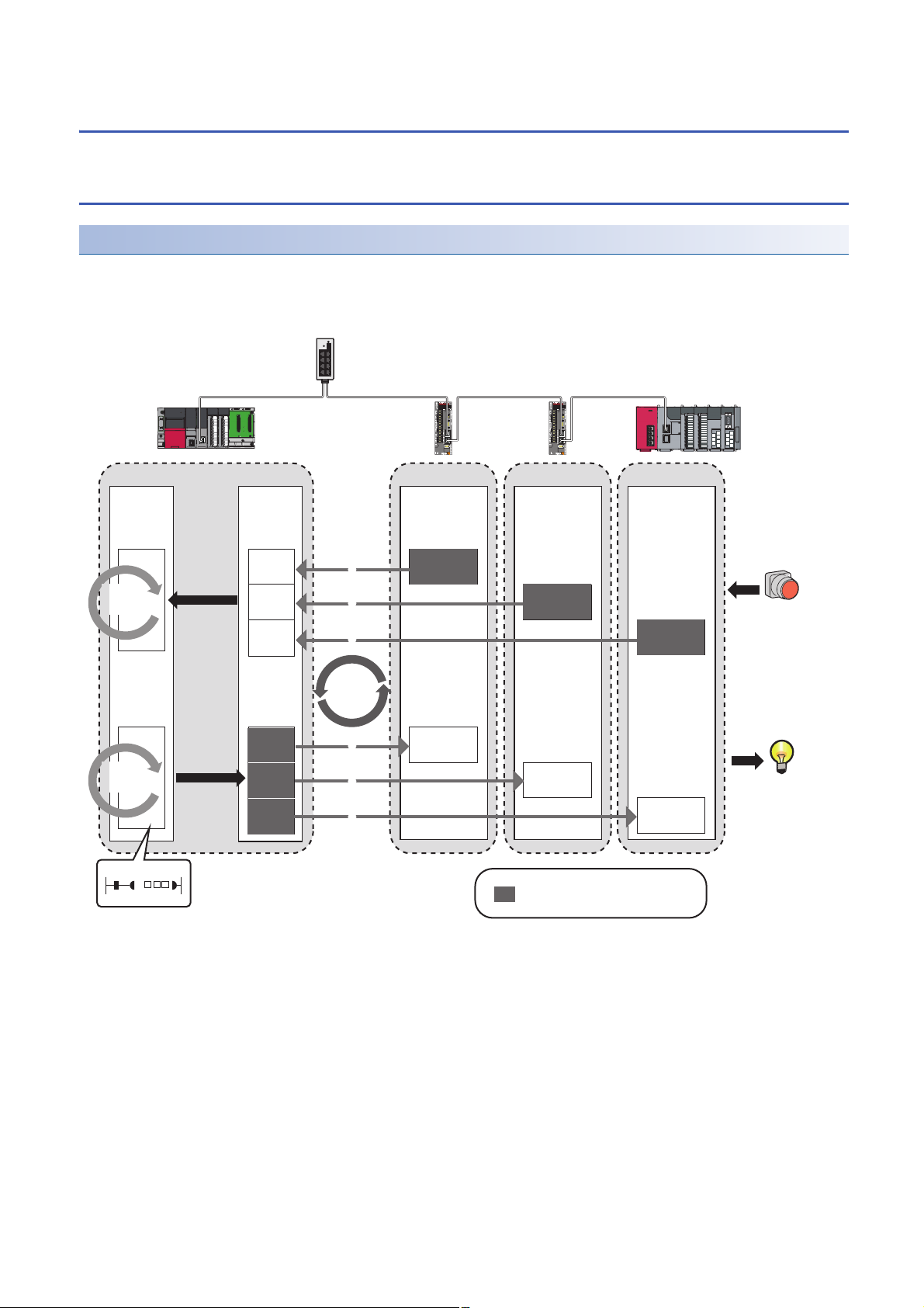
This function allows data to be periodically exchanged among stations on the same network using link devices.
Data flow and link device assignment
Master station and slave stations (except for local stations)
One-to-one communication is possible between the master and slave stations. The status data of the link devices (RY, RWw)
of the master station is output to the external device of the slave station, and the input status information from the external
device of the slave station is stored in the link devices (RX, RWr) of the master station.
18
*1 There is no RX or RY depending on the slave module.
• Output from the master station
The device of the CPU module turns on.
The status data of the device of the CPU module are stored in the link devices (RY, RWw) of the master station by link refresh.
The status data of the link devices (RY, RWw) of the master station are stored in the link devices (RY, RWw) of each slave station by link scan.
The status data of the link devices (RY, RWw) of the slave station are output to the external device.
• Input from the slave station
The status data of the external device are stored in the link devices (RX, RWr) of the slave station.
The status data of the link devices (RX, RWr) of the slave station are stored in the link devices (RX, RWr) of the master station by link scan.
The status data of the link devices (RX, RWr) of the master station are stored in the devices of the CPU module by link refresh.
1 FUNCTIONS
1.3 Cyclic Transmission
Page 21
Master station and local stations
M0
END
END
M0
END
END
Ò
Ó
Ô
Õ
×
Ö
Ù
Ø
Y
Y
RX, RWr
RY, RWw
RX, RWr
RY, RWw
RX, RWr
RY, RWw
RX, RWr
RY, RWw
Inter-module
synchronization
cycle
Inter-module
synchronization
cycle
Local station
Station No.1
Local station
Station No.2
Local station
Station No.3Station No.0
Area where data is sent to
other stations
Range of the
station No.1
sending data
Range of the
station No.2
sending data
Range of the
station No.3
sending data
Range of the
sending data to
the station No.1
Range of the
sending data to
the station No.2
Range of the
sending data to
the station No.3
Sequence
scan
Sequence
scan
Station
No.1
Station
No.2
Station
No.3
Station
No.1
Station
No.2
Station
No.3
Station
No.2
Station
No.3
Station
No.1
Station
No.2
Station
No.3
Station
No.1
Station
No.3
Station
No.1
Station
No.2
Station
No.1
Station
No.2
Station
No.3
CPU module CPU module
Device
Device
Device
Device
Link
refresh
Link
refresh
Link
refresh
Link
refresh
Link
scan
Master
station
(Simple
Motion
module)
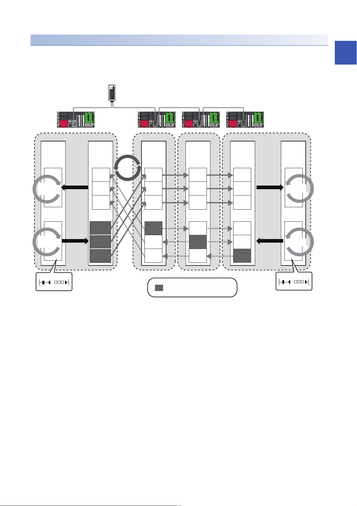
Data can be written into the send range of the link devices (RY, RWw) of each station and can be sent to any station on the
same network. The status data of the link devices (RY, RWw) of the master station are stored in the link devices (RX, RWr) of
each local station. The status data of the link devices (RY, RWw) of local stations are stored in the link devices (RX, RWr) of
the master station and the link devices (RY, RWw) of other local stations.
1
• Output from the master station
The device of the CPU module turns on.
The status data of the device of the CPU module are stored in the link devices (RY, RWw) of the master station by link refresh.
The status data of the link devices (RY, RWw) of the master station are stored in the link devices (RX, RWr) of the local station by link scan.
The status data of the link devices (RX, RWr) of the local station are stored in the devices of the CPU module.
• Input from the local station
The device of the CPU module turns on.
The device status data of the CPU module are stored in the own station send range of the link devices (RY, RWw).
The status data of the link devices (RY, RWw) of the local station are stored in the link devices (RX, RWr) of the master station by link scan.
The status data of the link devices (RX, RWr) of the master station are stored in the devices of the CPU module by link refresh.
1.3 Cyclic Transmission
1 FUNCTIONS
19
Page 22
Coexistence of local stations and the other slave stations (other than local stations)
RX, RWr
RY, RWw
*1
RX, RWr
*1
RY, RWw
*1
RX, RWr
RY, RWw
RX, RWr
RY, RWw
Master
station
(Simple
Motion
module)
Slave station
Station No.1
Slave station
Station No.2 Station No.3Station No.0
Local station
Area where data is sent to
other stations
Range of the
station No.1
sending data
Range of the
station No.2
sending data
Range of the
sending data to
the station No.1
Range of the
sending data to
the station No.2
Range of the
sending data to
the station No.3
CPU module
Station
No.1
Station
No.2
Station
No.1
Station
No.2
Station
No.1
Station
No.2
Station
No.3
Station
No.1
Station
No.2
Station
No.3
Device
Device
*1
Range of the
station No.3
sending data
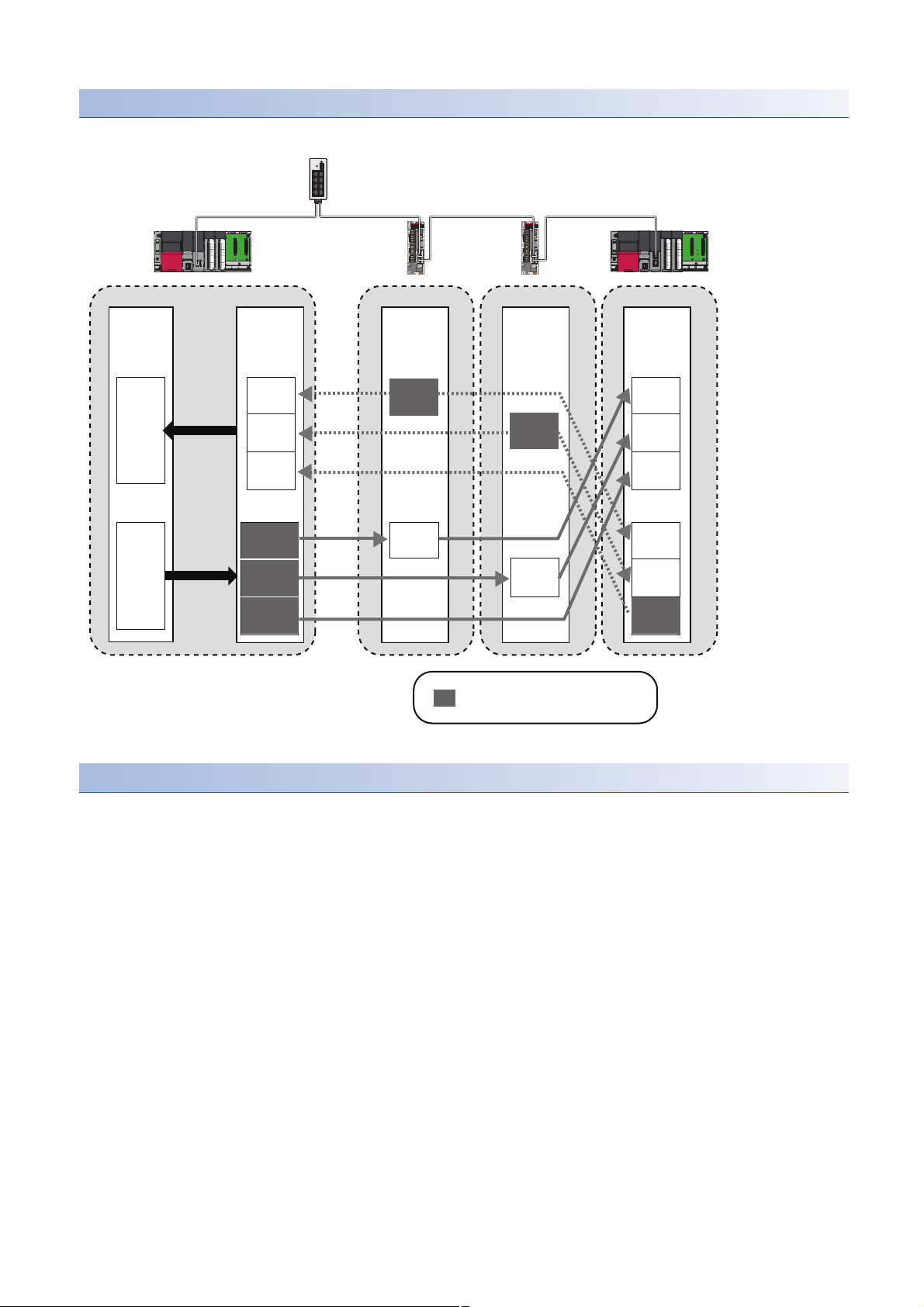
The data of all slave stations are also stored in the local stations in the same way as the master station.
*1 There is no RX or RY depending on the slave module.
Setting method
The link devices can be assigned in "Network Configuration Settings" under "Basic Settings". (Page 67 Network
Configuration Settings)
The link refresh is assigned in "Refresh Settings" under "Basic Settings". (Page 70 Refresh Settings)
20
1 FUNCTIONS
1.3 Cyclic Transmission
Page 23
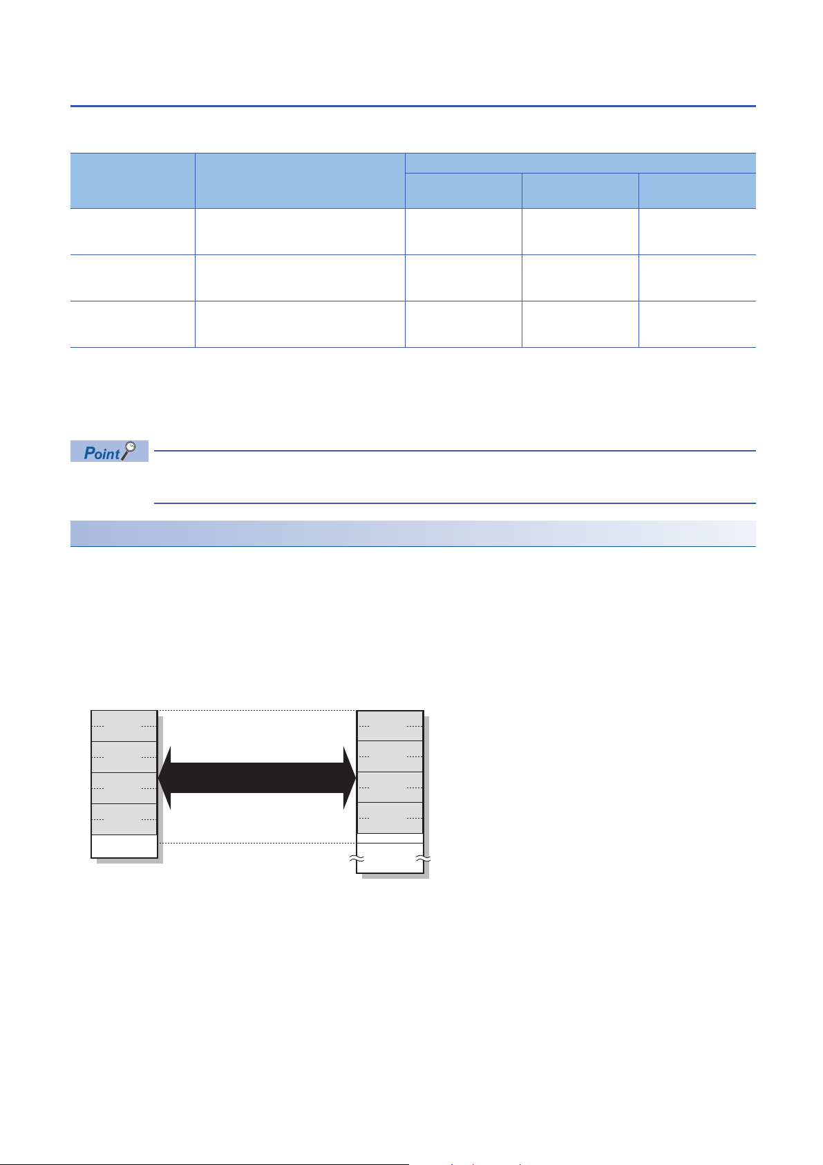
Link refresh
RX
RY
RWr
RWw
CPU module
Device
Link refresh
Simple Motion module
Link device
(1)
(2) (3)
CPU module
Device
Simple Motion
module
Link device
Link refresh
Link refresh
Link refresh
Empty
Empty
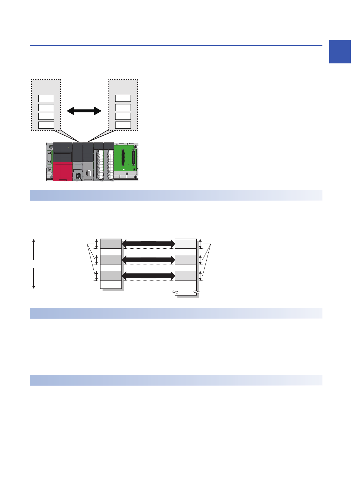
This function automatically transfers data between the link devices of the Simple Motion module and the devices of the CPU
module.
Concept of the link refresh range (number of points)
The link refresh is performed to the area set in "Refresh Settings" under "Basic Settings" and also specified in "Network
Configuration Settings" under "Basic Settings".
(1) Range set in "Refresh Settings" under "Basic
Settings"
(2) Actual link refresh range
(3) Range set in "Network Configuration Settings"
under "Basic Settings"
1
Shortening the link refresh time and transmission delay time
The link refresh time and transmission delay time can be shortened by reducing the number of link refresh points to the CPU
module. The following methods can be used to reduce the number of the link refresh points.
• In "Refresh Settings" under "Basic Settings", set only the link devices used in the CPU module as the link refresh range.
(Page 70 Refresh Settings)
• Directly access infrequently used link devices from the program, and remove the corresponding settings from the link
refresh range. (Page 23 Direct access to link devices)
Setting method
The link refresh is assigned in "Refresh Settings" under "Basic Settings". (Page 70 Refresh Settings)
1 FUNCTIONS
1.3 Cyclic Transmission
21
Page 24

Precautions
■Latched devices of the CPU module
If data in latched devices of the CPU module are cleared to zero on a program when the CPU module is powered off and on
or reset, the data may be output without being cleared to zero, depending on the timing of the link scan and link refresh. Take
the following actions not to output the data in the latched devices of the CPU module.
CPU module device How to disable the device data
Latch relay (L), file register (R, ZR) Use the initial device value of the CPU module to clear the device to zero.
CPU module device within the latch range Delete all the latch range settings specified in "Latch Interval Operation
Setting" under "Device Latch Interval Setting" in "Memory/Device Setting" of
"CPU Parameter".
*1 For the initial device value setting of the CPU module, refer to the following.
GX Works3 Operating Manual
When the inter-module synchronization setting is set to "Not Use", the link device (RX/RY/RWr/RWw) of the
station whose network synchronous communication is set to "Synchronous" is not refreshed.
*1
22
1 FUNCTIONS
1.3 Cyclic Transmission
Page 25

Direct access to link devices
Ex.
J
(1) (2)
__
\
RWw100 RWw100
RWr100 RWr100
RY1000
RY1000
RX1100RX1100
XYWRX
RWr RWw
RY RX RY
RWr RWw
Master station Slave station
Network No.1
Simple Motion
module
Send
request
CPU module Slave station
Cyclic transmission
MOV K20 J1\W100
= J1\W2100 K300
J1\X1100
J1\Y1000
Actual I/O
This function directly accesses the link devices (RX, RY, RWr, RWw, SB, or SW) of the Simple Motion module from the
program. Specify a link device as the link direct device (J_\_) for direct access.
Specification method
Specify the network No. and the link device of the Simple Motion module for reading or writing.
(1) Network No.: 1 to 239
(2) Remote input (RX): X0 to X3FFF
Remote output (RY): Y0 to Y3FFF
Remote register (RWw): W0 to W1FFF
Remote register (RWr): W2000 to W3FFF
Link special relay (SB): SB0 to SB1FF
Link special register (SW): SW0 to SW1FF
1
1 FUNCTIONS
1.3 Cyclic Transmission
23
Page 26
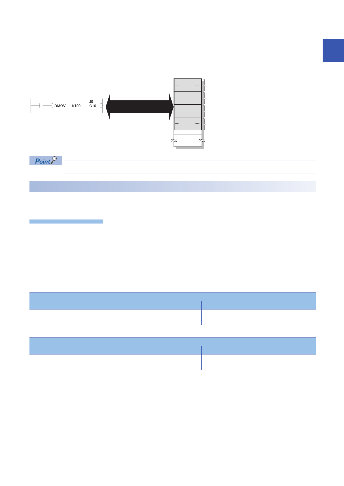
Readable and writable range
Ex.
(2)
(1)
(3)
Y
RY
CPU module Simple Motion module
This area is
writable.
Link refresh
Link refresh
RWw
20 RWw100
W
W100
20
Simple Motion moduleCPU module
MOV K20 J1\W100
Link refresh
MOV K20 W100
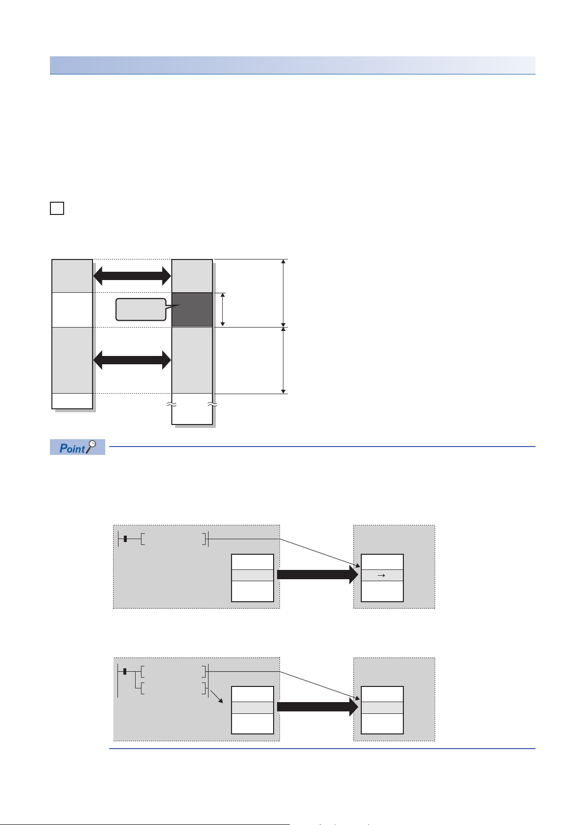
Data can be read or written between the Simple Motion module and CPU module mounted on the same base unit.
■Read
All link devices of the Simple Motion module can be specified. (Page 23 Specification method)
■Write
The range that satisfies all of the following conditions can be specified.
• Area where data is sent to other stations and outside the link refresh range (Page 18 Data flow and link device
assignment)
• Within the link device range of the Simple Motion module (Page 23 Specification method)
The following shows the example.
(1) Out of the link refresh range
(2) Area where data is sent to other stations
(3) Area for receiving the data from other stations
When writing data to the area in the link refresh range, directly access the link device and write the same data
in the device of the CPU module.
• Bad example (Only direct access to the link refresh target)
Link refresh overwrites the value.
MOV K20 J1\W100
• Good example (In addition to direct access, writing the same data to the CPU module device)
The value written by direct access is reflected.
Simple Motion moduleCPU module
W
300W100
Link refresh
RWw
20 300 RWw100
24
1 FUNCTIONS
1.3 Cyclic Transmission
Page 27

Differences from link refresh
Item Access method
Link refresh Direct access
Number of steps 1 step 2 steps
Processing speed
Cyclic data integrity assurance Available Not available
*1 For actual values, refer to the following.
MELSEC iQ-R Programming Manual (CPU Module Instructions, Standard Functions/Function Blocks)
*1
High speed Low speed
Shortening the link refresh time and transmission delay time
■Shortening the link refresh time
Remove infrequently used link devices from the link refresh range, and directly read or write the corresponding data using link
direct devices. This reduces the number of the link refresh points to the CPU module, resulting in a shorter link refresh time.
(Page 21 Link refresh)
■Shortening the transmission delay time
Because the link direct device allows direct reading or writing of data to the link devices of the Simple Motion module at the
time of the instruction execution, the transmission delay time can be shortened.
Link refresh is executed in END processing of the sequence scan of the CPU module.
Precautions
1
■Cyclic data integrity assurance
Direct access to link devices does not provide station-based block data assurance. Use 32-bit data assurance, or if cyclic data
of more than 32 bits needs to be assured, use interlock programs. (Page 26 Cyclic data integrity assurance)
■Mounting multiple modules of the same network No.
When multiple Simple Motion modules of the same network No. are mounted, the target of direct access is the module which
has the smallest slot No. in the base unit.
■Link direct device in a multiple CPU system
In a multiple CPU system, link direct devices cannot be used for the CC-Link IE Controller Network-equipped module
controlled by another CPU module.
1 FUNCTIONS
1.3 Cyclic Transmission
25
Page 28
Cyclic data integrity assurance
0H
1H
2H
3H
4H
5H
6H
7H
RWr, RWw
2 words
(32 bits)
Simple Motion module
Device
CPU module
Link refresh
2 words
(32 bits)
2 words
(32 bits)
2 words
(32 bits)
2 words
(32 bits)
2 words
(32 bits)
2 words
(32 bits)
2 words
(32 bits)
This function assures the cyclic data integrity in units of 32 bits or station-based units.
: Assured, : Not assured
Method Description Availability
Link refresh Direct access to
link devices
32-bit data assurance Assures data in 32-bit units.
Station-based block data
assurance
Interlock program Assures data of more than 32 bits.
*1
Data is automatically assured by satisfying
assignment conditions of link devices.
Assures data in station-based units.
Data is assured by enabling the station-based
block data assurance in the parameter setting.
Data is assured by configuring interlocks on
programs.
*1 When the software version of the Simple Motion module is "Ver.01":
The set parameter is ignored in the Simple Motion module and operate as "Disable". Assure data using interlock programs as required.
When the software version of the Simple Motion module is "Ver.02" or later:
To enable data assurance in an asynchronous station, read/write data by direct access in the inter-module synchronous interrupt
program (I44) without using a link refresh.
When there is a remote device station in the network, use station-based block data assurance. If it is disabled,
the functions of the remote device station cannot be assured.
Access to buffer
memory
32-bit data assurance
The RWr and RWw data can be assured in 32-bit units.
■Data assurance at the time of direct access to link devices
When link refresh target devices are accessed, the integrity of 32-bit data can be assured by satisfying the following
conditions.
• The start device No. of RWr, RWw is multiples of 2.
• The number of points assigned to RWr, RWw is multiples of 2.
26
1 FUNCTIONS
1.3 Cyclic Transmission
Page 29
■Data integrity assurance at the time of access to buffer memory
Precautions
0H
1H
2H
3H
4H
5H
6H
7H
2 words
(32 bits)
Buffer memory
Simple Motion module
2 words
(32 bits)
2 words
(32 bits)
2 words
(32 bits)
DMOV instruction
\
The integrity of 32-bit data can be assured by satisfying the following conditions.
• Access using the DMOV instruction
• The start address of the buffer memory is multiples of 2.
For data assurance of more than 32 bits, use station-based block data assurance or interlock programs.
Station-based block data assurance
Integrity of the cyclic data is assured for each station by handshake between the CPU module and Simple Motion module for
a link refresh.
1
• When the software version of the Simple Motion module is "Ver.01":
The set parameter is ignored in the Simple Motion module and operate as "Disable". Assure data using interlock programs
as required.
• When the software version of the Simple Motion module is "Ver.02" or later:
To enable data assurance in an asynchronous station, read/write data by direct access in the inter-module synchronous
interrupt program (I44) without using a link refresh. There are restrictions on the operation by the inter-module
synchronization setting, operation mode, and network synchronous communication.
<Inter-module synchronization valid>
Operation mode Network communication setting
Synchronous Asynchronous
High-speed Enable Disable
Normal Enable Enable
<Inter-module synchronization invalid>
Operation mode Network communication setting
Synchronous Asynchronous
High-speed Disable Disable
Normal Disable Enable
■Setting
Set station-based block data assurance under "Supplementary Cyclic Settings" in "Application Settings" of the master station.
(Page 74 Application Settings)
Once this setting is enabled on the master station, integrity of the data for all stations is assured for each station.
1 FUNCTIONS
1.3 Cyclic Transmission
27
Page 30
■Access to link devices
Station
No.1
Station
No.2
Station
No.3
Station
No.4
Data
assurance
Data
assurance
Data
assurance
Data
assurance
Data
assurance
Data
assurance
Data
assurance
Data
assurance
Station
No.1
Station
No.2
Station
No.3
Station
No.4
Link device
Simple Motion module
Device
CPU module
Link refresh
Simple Motion module
Master/local module
Receiving stationSending station
Master station
(station No.0)
Local station
(station No.1)
SET Y1000
X1000
Y1000
RX0
RY0RY0
RWw0
RWr0
RWw0
RWr0
RX0
Y1000
W0
W1000
W0
W1000
X1000
X1000
Send
request
Send data (W)
CPU
module
Master
station
CPU
module
Local
station
Cyclic transmission
Link refresh
Receive data (W)
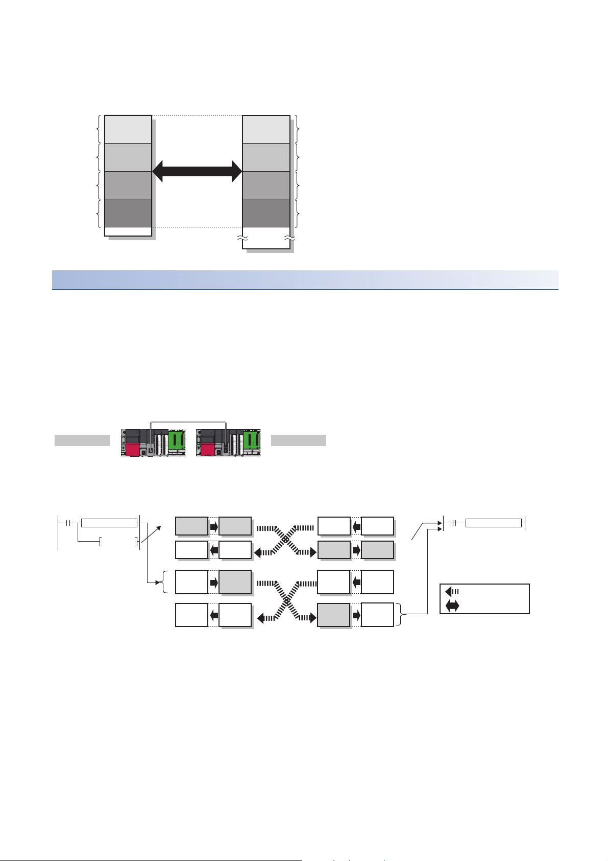
During a link refresh, data are assured for each station as shown below.
Interlock program
Data of more than 32 bits can be assured with the station-based block data assurance setting disabled. Use either of the
following methods.
• Interlock using X and Y
• Interlock using devices other than X and Y (when X, Y cannot be used as an interlock device)
■Example of interlock using X and Y
An example of sending data in W0 to W3 of the master station (station No.0) to W1000 to W1003 of the local station (station
No.1) is shown below. (X1000 and Y1000 are used for a handshake to the CPU module.)
• Data flow
28
1 FUNCTIONS
1.3 Cyclic Transmission
Page 31

•Program
Program example
Sending station: Master station (station No.0)
Classification Description
Label to be defined Define global labels as shown below:
Receiving station: Local station (station No.1)
Classification Description
Label to be defined Define global labels as shown below:
1
• Program flow
Sending station (0) "bStartDirection" (M0) is turned on.
Sending station (0) The contents of "uTransferFrom" (D0 to D3) are stored in W0 to W3.
Sending station (0) Upon completion of storage in W0 to W3, turn on Y1000 of the sending station for a handshake.
Receiving station (0) Cyclic transmission sends RWw followed by RY, and X1000 of the receiving station turns on.
Receiving station (0) The contents of W1000 to W1003 are stored in "uTransferTo" (D0 to D3).
Receiving station (0) Upon completion of storage in "uTransferTo" (D0 to D3), turn on Y1000 of the receiving station for a handshake.
Sending station (23) When X1000 of the sending station turns on, turn off Y1000 of the sending station.
Receiving station (23) When X1000 of the receiving station turns off, turn off Y1000 of the receiving station.
1 FUNCTIONS
1.3 Cyclic Transmission
29
Page 32

■Example of interlock using devices other than X and Y
Program example
Simple Motion module
Master/local module
Receiving stationSending station
Master station
(station No.0)
Local station
(station No.1)
SET B0
RWw0
RWr0
RWr3F0
RWw0
RWr0
RWr3F0
RWw3F0 RWw3F0
W0
B0
B1000
W1000
W0
B0
B1000
W1000
B1000
Cyclic transmission
Link refresh
Send
request
CPU
module
Master
station
CPU
module
Local
station
Send data (W)
Receive data (W)
An example of sending data in W0 to W3 of the master station (station No.0) to W1000 to W1003 of the local station (station
No.1) is shown below. This is a method used when X and Y cannot be used as interlock devices. (B0 and B1000 are used for
a handshake to the CPU module.)
• Data flow
•Program
Sending station: Master station (station No.0)
Classification Description
Label to be defined Define global labels as shown below:
30
1 FUNCTIONS
1.3 Cyclic Transmission
Page 33

Receiving station: Local station (station No.1)
Classification Description
Label to be defined Define global labels as shown below:
• Program flow
Sending station (0) "bStartDirection" (M0) is turned on.
Sending station (0) The contents of "uTransferFrom" (D0 to D3) are stored in W0 to W3.
Sending station (0) Upon completion of storage in W0 to W3, turn on B0 of the sending station for a handshake.
Receiving station (0) Cyclic transmission sends signals from RWw0 to RWw3EF followed by RWw3F0 and stores them in RWr0 to RWr3EF and RWr3F0 in
this order at the receiving station. B1000 of the receiving station turns on.
Receiving station (0) The contents of W1000 to W1003 are stored in "uTransferTo" (D0 to D3).
Receiving station (0) Upon completion of storage in "uTransferTo" (D0 to D3), turn on B0 of the receiving station for a handshake.
Sending station (23) When B1000 of the sending station turns on, turn off B0 of the sending station.
Receiving station (23) When B1000 of the receiving station turns off, turn off B0 of the receiving station.
1
1 FUNCTIONS
1.3 Cyclic Transmission
31
Page 34

Interlink transmission
RX
RY
LB
Relay station
Interlink
transmissions
Network
module
Simple Motion
module
Network No.1 Network No.2
Data of network No.2
Data of network No.1
This function transfers data in the link devices of the master station to another network module on a relay station.
Setting method
Set interlink transmission in "Interlink Transmission Settings" in "Application Settings". (Page 77 Interlink Transmission
Settings)
Precautions
For the precautions, refer to the following.
Page 77 Interlink Transmission Settings
32
1 FUNCTIONS
1.3 Cyclic Transmission
Page 35

Input and output status settings when failure occurs
RX
RY
RWw
RWr
RX
RY
RWw
RWr
RY
RX
RWr
RWw
RY
RX
RWr
RWw
Master station
(Simple Motion
module)
Station No.0
Station
No.3
Station
No.2
Station
No.1
Station
No.3
Station
No.2
Station
No.1
Station
No.3
Station
No.2
Station
No.1
Station
No.3
Station
No.2
Station
No.2
Station
No.1
Station
No.1
Station
No.1
Station
No.1
Station
No.3
Station
No.3
Station
No.2
Station
No.1
Station
No.3
Station
No.2
Station
No.1
Station
No.3
Station
No.2
Station
No.1
Station
No.3
Station
No.2
Station
No.1
Slave station
(other than a
local station)
Station No.1
Station
No.1
Local
station
Station No.2
Local
station
Station No.3
Station
No.3
Station
No.2
Station
No.1
Station
No.3
Station
No.1
Station
No.3
Station
No.2
Station
No.1
Station
No.2
Station
No.1
Area for which "Clear" or "Hold" can be selected in the data link faulty station input status setting
Area for which "Clear" or "Hold" can be selected in the cyclic output setting for a stop error of
the CPU module
Area where data are held regardless of the setting
Area that depends on the setting of the slave station (other than a local station)
For the Simple Motion module, status of input from a data link faulty station and output status of cyclic data if a stop error
occurs in the CPU module can be set.
Status Range where the settings are enabled
Input status of data link faulty station Whether to clear or hold the following RX input data can be selected.
• Master station RX
Even if "Clear" is set, input data will be held for two seconds after
communication failure such as Ethernet cable disconnection.
The RWr input data is held regardless of the setting.
• Master station RWr
Cyclic data output when a stop error occurs in the CPU module Whether to clear or hold the RY data (only the output data from the own
station) of the master station can be selected.
1
1 FUNCTIONS
1.3 Cyclic Transmission
33
Page 36

Setting method
■Input status of data link faulty station
Set the input status of data link faulty stations under "Supplementary Cyclic Settings" in "Application Settings". (Page 74
Application Settings)
■Cyclic data output when a stop error occurs in the CPU module
Under "Supplementary Cyclic Settings" in "Application Settings", set the cyclic data output status for when a stop error occurs
in the CPU module. (Page 74 Application Settings)
Precautions
■When data link is stopped by users
When cyclic transmission is stopped using one of the following methods, the input status of the own station is held even if
"Data Link Error Station Setting" under "I/O Maintenance Settings" is set to "Clear" under "Supplementary Cyclic Settings" in
"Application Settings".
• CC-Link IE Field Network diagnostics (Page 105 Checking the Network Status)
• Link special relay (SB), link special register (SW) (Page 143 List of Link Special Relay (SB), Page 152 List of Link
Special Register (SW))
■When a stop error of the CPU module occurs on a station with a data link error
When "Hold" is set to the following settings, the input status of the own station is held eve if "Data Link Error Station Setting"
under "I/O Maintenance Settings" is set to "Clear" under "Supplementary Cyclic Settings" in "Application Settings".
• "Output Hold/Clear Setting during CPU STOP" under "I/O Maintenance Settings" under "Supplementary Cyclic Settings" in
"Application Settings"
• "Output Mode upon CPU Error" under "I/O Maintenance Settings" of "Supplementary Cyclic Settings" in "Application
Settings"
Output status setting for CPU STOP
When the CPU module mounted with the Simple Motion module is set to STOP, whether cyclic data output is held or cleared
can be selected.
Setting method
Under "Supplementary Cyclic Settings" in "Application Settings", set the output status for the case where the CPU module
switch is set to STOP. (Page 74 Application Settings)
Precautions
■When the setting is disabled
When the link refresh source of RY is set to Y, the cyclic data output is cleared even if the output status setting for CPU STOP
is set to be held. For RWw, the cyclic data output is held regardless of the device of the link refresh source, even if the output
status setting for CPU STOP is set to be cleared.
■When the output status setting for CPU STOP is set to clear
When the CPU module is in the STOP state, the forced output to slave stations cannot be executed using the engineering
tool.
■When data is refreshed by a link direct device
The output status for CPU STOP depends on the parameter specified in "Output Hold/Clear Setting during CPU STOP" under
"I/O Maintenance Settings" under "Supplementary Cyclic Settings" in "Application Settings".
■When the Safety CPU is used
When the Safety CPU is in the safety mode, output of safety communications will be cleared even if "Hold" is set in "Output
Hold/Clear Setting during CPU STOP" of "I/O Maintenance Settings" under "Supplementary Cyclic Settings" in "Application
Settings".
34
1 FUNCTIONS
1.3 Cyclic Transmission
Page 37

Cyclic transmission stop and restart
This function stops the cyclic transmission during debugging and other operations. (Data reception from a slave station and
data sending from the own station are stopped.) Also, the stopped cyclic transmission can be restarted. Transient
transmission does not stop.
Cyclic transmission is stopped and restarted using the link start/stop of the CC-Link IE Field Network diagnostics. (Page
117 Link Start/Stop)
1
1 FUNCTIONS
1.3 Cyclic Transmission
35
Page 38

1.4 Transient Transmission
Ex.
1
2
3
READ
1234H 1234H
Command
Device Device
CPU module CPU module
Master station
(Simple Motion module)
Local station
This function allows communications with other stations when a request is made by a method such as a dedicated instruction
and engineering tool. Communications with different networks is also possible.
Communications within the same network
This function performs the transient transmission to other stations using dedicated instructions and the engineering tool. For
details on the dedicated instructions that can be used, refer to the following.
Page 166 Dedicated Instruction
Accessing a programmable controller of another station using the dedicated instruction (READ instruction)
36
1 FUNCTIONS
1.4 Transient Transmission
Page 39

Communications with different networks
Ethernet
CC-Link IE Field Network
CC-Link IE Controller Network
Network No.3 Network No.2
Network No.1
(Relay station (Simple Motion module))
Engineering tool
This function performs the transient transmission seamlessly to stations on different networks using dedicated instructions
and the engineering tool.
1
Communications can be made with stations up to eight networks apart (number of relay stations: 7).
(Page 166 Dedicated Instruction)
When the networks consist of only MELSEC iQ-R series
Communication paths are automatically set for communication with the following networks of MELSEC iQ-R series.
• Ethernet
• CC-Link IE Controller Network
• CC-Link IE Field Network
■Setting method
Check that "Dynamic Routing" in "Application Settings" is set to "Enable".
• Communication paths are automatically set, but they can also be manually set. (Page 38 When the
networks consist of MELSEC iQ-R series and other series)
• Communication paths cannot be automatically set to Ethernet-equipped modules connected via a router.
Set communication paths manually for such modules. (Page 38 When the networks consist of MELSEC
iQ-R series and other series)
1 FUNCTIONS
1.4 Transient Transmission
37
Page 40

When the networks consist of MELSEC iQ-R series and other series
Communication
target
Own station
(request source)
(Simple Motion module)
CC-Link IE
Field Network
CC-Link IE
Field Network
CC-Link IE
Field Network
Station
No.2
Station
No.1
Station
No.3
Station
No.0
Station
No.0
Station
No.2
Station
No.4
Station
No.0
(Relay
station 1)
Station
No.2
Station
No.3
(Relay
station 2)
Station
No.1
Network No.1 Network No.3
Network No.2
Setting communication paths allows communication with the following networks configured with modules other than MELSEC
iQ-R series.
• Ethernet
• CC-Link IE Controller Network
• CC-Link IE Field Network
• MELSECNET/H
• MELSECNET/10
■Setting method
Set communication paths in "Routing Setting" of "CPU Parameter". (MELSEC iQ-R CPU Module User's Manual
(Application))
Communication test
Communication test checks if transient transmission data can be properly routed from the own station to the communication
target.
Take the following system configuration as an example of communication test procedure.
1. Open the "Communication Test" window and enter
values for "Target Station" and "Communication Data
Setting".
[Diagnostics] [CC-Link IE Field Diagnostics]
[Communication Test] button
2. Click the [Execute Test] button to execute the
communication test. If an error occurs, take corrective
actions according to the error message.
38
1 FUNCTIONS
1.4 Transient Transmission
Page 41

Precautions
• When a relay sending station is set to "Target Station", only an error code appears without an error message. Set a relay
Own station
(request source)
Station
No.0
Station
No.1
Station
No.2
Receiving
(relay) station
Sending
(relay) station
Station
No.0
Network No.1
Network No.2
receiving station to "Target Station".
• When a station mounted on top of the same base unit (main base unit and extension base unit) is set to "Target Station",
only an error code appears without an error message. Set a station mounted on the different base unit to "Target Station".
1
1 FUNCTIONS
1.4 Transient Transmission
39
Page 42

1.5 IP Packet Transfer Function
Only CC-Link IE Field Network is
required to perform communications
using an IP address.
CC-Link IE Field Network
Ethernet communications (IP packet transfer)
Simple Motion
module
This function enables communications using the specified IP address over CC-Link IE Field Network.
For example, a personal computer can communicate with the FTP server.
With this function, two networks of CC-Link IE Field Network and Ethernet are not required, resulting in reduced wiring cost.
The data that are communicated using the IP packet transfer function are communicated separately by the
link scan of the CC-Link IE Controller Network.
Because of this, the speed of communications using the IP packet transfer function is slower than the speed
of communications with the Ethernet line.
40
1 FUNCTIONS
1.5 IP Packet Transfer Function
Page 43

System configuration
(1) (2)
(3)
(4) (4)
(3)
Simple Motion
module
Simple Motion
module
Ethernet device
(request source device)
Modules supporting the CC-Link IE Field Network
gateway setting
(e.g. Ethernet adapter module)
Ethernet device
(request destination device)
The IP packet transfer function allows communications to be performed by connecting an Ethernet device to one of the
following devices.
Connecting Ethernet devices
■Connecting an Ethernet device to an Ethernet-equipped module
Connect an Ethernet device to an Ethernet-equipped module.
(1) Ethernet device (request source device)
(2) Ethernet device (request destination device)
(3) Ethernet
(4) CC-Link IE Field Network
The IP packet transfer function can be used on the remote head module. An Ethernet device can also be
connected by mounting the RJ71EN71 on the remote head module.
■Connecting an Ethernet device to a module compatible with the CC-Link IE Field Network
gateway setting
Connect an Ethernet device to a module compatible with the CC-Link IE Field Network gateway setting (such as an Ethernet
adapter module).
Doing so allows communications to be performed with an Ethernet device having a different network address.
1
1.5 IP Packet Transfer Function
1 FUNCTIONS
41
Page 44

Setting
Ò Ò
Ó, Ô, Õ, Ö, ×Ó, Ô, Õ, Ö, ×Ö, ×
Ethernet device
(request source device)
Ethernet device
(request destination device)
: Communication route
Simple Motion
module
To use the IP packet transfer function, the following items need to be set.
Ethernet device gateway address setting
Set the IP address of the Ethernet-equipped module connected to an Ethernet device in the gateway address of the Ethernet device used.
IP address setting of the Ethernet-equipped module (Page 45 Setting in the Ethernet-equipped module)
Setting of the network No. and station No. of the RJ71EN71 or the R nENCPU (network part) connected to the Ethernet device
When the RJ71EN71 or the RnENCPU (network part) is set for the Ethernet-equipped module connected to the Ethernet device, set "Communications by
Network No./Station No." in the module parameter of the Ethernet to "Enable".
IP packet transfer setting (Page 45 Setting in the Ethernet-equipped module)
This setting is required for the IP packet to be passed between an Ethernet-equipped module and a relay station.
IP address setting of a Simple Motion module (Page 45 Setting in the master station)
Routing parameter setting
Set routing parameters in the following cases. (Page 46 Routing parameter setting)
When modules other than MELSEC iQ-R series exist in the communication path
When an Ethernet device needs to be connected to a module that does not support routing parameters
• When the Ethernet device is a personal computer (only Ethernet devices having the route command, such
as Microsoft Windows), it is recommended to set the gateway address using the route command. If the
gateway address is set in the default gateway, packets not related to the IP packet transfer are also
transmitted through the CPU module. Consequently, the service processing of the CPU module drops under
heavy load, causing other service processings to be slow or other problems. For the gateway address
setting of when an Ethernet device is connected to a module other than an Ethernet-equipped module, refer
to the manual for the module connected to the Ethernet device.
• After the setting is completed, execute the IP communication test to check for an error in the communication
path. (Page 47 IP communication test)
42
1 FUNCTIONS
1.5 IP Packet Transfer Function
Page 45

Rules for the IP address setting
IP addresses specified for the IP packet transfer function need to satisfy the following rules.
Device to be set Setting range of the IP address
First and second octets Third octet Fourth octet
Ethernet device
Ethernet-equipped module connected
to the Ethernet device
Simple Motion module ,
Remote head module
Simple Motion module on the
communication path (not connected to
an Ethernet device)
0.0 to 223.255
(Same Nos. for the request source
device, request destination device,
and modules between them)
Automatically set (Same value as the
master station)
0.0 to 223.255
IP address setting not required
*1
*1 Set the Nos. according to the range applicable to the Ethernet device used. The range may not apply depending on the Ethernet device.
Check the specifications of the Ethernet device used.
, ,
*1
1 to 239
(Same No. for the Ethernet device
and the Ethernet-equipped module)
Automatically set (network No. of the
own station)
1 to 239
*1
1 to 120
Automatically set (station No. of the
own station)
• 1 to 120
• 125 (125 is always set in the
master station.)
1
1 FUNCTIONS
1.5 IP Packet Transfer Function
43
Page 46

Use the same Nos. for the first and second octets of the IP addresses of the request source device, request destination device, and modules between them.
192 . 168 . 10 . 36
The first and second octets (network addresses)
192 . 168 . 10 . 36
The third octet
The fourth octet
192.168.10.11 192.168.10.36
192.168.2.125 192.168.7.18
192.168. 2.8
Ethernet device
(request source device)
Network No.10
Network No.2
Ethernetequipped
module
Master
station
Station
No.0
Ethernetequipped
module
Local
station
Station
No.8
Local
station
Station
No.18
IP address setting
not required
192.168.10.1 192.168.21.2192.168.10.2 192.168.21.1
Ethernet
Ethernet
*2
Ethernet
CC-Link IE Field Network
Do not use the same network Nos. for those highlighted.
Network No.10 Network No.21Network No.1
Network No.32
Network No.2
Simple Motion module
For the IP addresses of the Ethernet-equipped modules, set a No. between 1 and 239 for the third octet and a No. between 1 and 120 for the fourth octet.
The network No. of the own station is automatically assigned to the third octet of the IP address of the Simple Motion module and remote head modules
each. The station No. of the own station is automatically assigned to the fourth octet of the IP address of the Simple Motion module or remote head modules
each. (The fourth octet of the IP address of the master station is always 125.)
Use the same No. for the third octet (network No.) of the IP addresses of an Ethernet device and a Ethernet-equipped module connected to the Ethernet
device.
Do not use the third octet (network No.) of the IP address same as that of other network modules and other CPU modules using the IP packet transfer
function.
*2 Do not use the same network Nos. for those of network modules other than the Simple Motion module.
The values in the first and second octets of the remote head module IP address are obtained from the master station IP address so that the same values as
those of the master station can be set.
44
1 FUNCTIONS
1.5 IP Packet Transfer Function
Page 47

■CC-Link IE Field Network gateway setting
Through a module, such as an Ethernet adapter module, where the CC-Link IE Field Network gateway can be set, any IP
address can be used for the Ethernet device side. (Page 49 Access range, Page 55 When an Ethernet device with a
different network address is accessed)
Note, however, that the network addresses on the CC-Link IE Field Network side must be the same.
For the IP address setting range, refer to the following table.
Device to be set Setting range of the IP address
First and second octets Third octet Fourth octet
Ethernet device Within the range applicable to the Ethernet device
Module compatible with the CC-Link IE
Field Network gateway setting
Simple Motion module 0.0 to 255.255 Automatically set (network No. of the
Remote head module Automatically set (Same value as the
Ethernet-equipped module on the
communication path (not connected to
an Ethernet device)
When setting the IP address in each device, do not use the IP addresses already used for other devices.
Within the range applicable to the module compatible with the CC-Link IE Field Network gateway setting (Manual
for the module compatible with the CC-Link IE Field Network gateway setting)
Automatically set (station No. of the
master station)
0.0 to 223.255
IP address setting not required
own station)
1 to 239
own station)
• 1 to 120
• 125 (125 is always set in the
master station.)
1
Setting method
For a communication example, refer to the following.
Page 53 Example of communications using the IP packet transfer function
■Setting in the Ethernet-equipped module
1. Set the IP address of the Ethernet-equipped module as follows.
Navigation window "Parameter" Ta r ge t m od u le "Module Parameter" "Basic Settings" "Own Node Settings"
"IP Address"
Follow the rules to set the IP address. (Page 43 Rules for the IP address setting)
2. Change the following setting to "Use".
Navigation window "Parameter" Ta r g e t m o d ul e "Module Parameter" "Application Settings" "IP Packet
Transfer Setting"
■Setting in the master station
1. Set the IP address of the master station as follows.
Navigation window "Parameter" "Module Information" Target module "Module Parameter (Network)"
"Application Settings" "IP Address"
Follow the rules to set the IP address. (Page 43 Rules for the IP address setting)
■Setting in the local stations
The IP address setting is not required for the local stations. The same network address as the master station is automatically
assigned to the first and second octets. The network No. of the own station is assigned to the third octet, and the station No.
of the own station is assigned to the fourth octet.
1 FUNCTIONS
1.5 IP Packet Transfer Function
45
Page 48

Routing parameter setting
Ex.
A
B
C
023121
223
Communication routes set using the routing parameters
Communication route automatically set (from a module that
does not have the routing parameters to the master station)
Setting for
Network No.
Relay station
Station
Setting for Setting for
The setting is not required
because the module does not
have the routing parameters.
Set this column to pass communications
through the master station.
Network No.
Target station
Network No.
Relay station
Station Network No.
Target station
ABC
Ethernet device
(request source device)
Ethernet device
(request destination device)
Local station
Master station
Network No.1 Network No.2 Network No.3
Station
No.2
Station
No.1
Station
No.0
Set routing parameters in the following cases.
• When modules other than MELSEC iQ-R series exist in the communication path
• When an Ethernet device needs to be connected to a module that does not support routing parameters
■When modules other than MELSEC iQ-R series exist in the communication path
To set routing parameters, refer to the following.
MELSEC iQ-R CPU Module User's Manual (Application)
■When an Ethernet device needs to be connected to a module that does not support routing
parameters
When an Ethernet device needs to be connected to a module, such as an Ethernet adapter module, that does not support
routing parameters, set the routing parameters so that communications are transmitted through the master station.
Communications from a module that does not have the routing parameters are automatically transmitted through the master
station. The communication paths must be the same for data sending and receiving; therefore, set the routing parameters so
that communications are transmitted through the master station.
Proper setting
1 FUNCTIONS
46
1.5 IP Packet Transfer Function
Page 49

Ex.
Improper setting
A
B
C
223121
Because the communication route for data sending is different
from that for data receiving, an error occurs.
*1
Communication routes set using the routing parameters
Communication route automatically set (from a module that
does not have the routing parameters to the master station)
Setting for
Network No.
Relay station
Station
Setting for Setting for
The setting is not required
because the module does not
have the routing parameters.
Network No.
Target station
Network No.
Relay station
Station Network No.
Target station
ABC
Ethernet device
(request source device)
Ethernet device
(request destination device)
Local station
Master station
Network No.1 Network No.2 Network No.3
Station
No.2
Station
No.1
Station
No.0
192.168.1.1 192.168.10.1
Network No.1 Network No.10
CPU module 1: 192.168.1.10
Master station (station No.0):
192.168.2.125
CPU module 2: 192.168.10.10
Local station (station No.2):
192.168.2.2
Network No.2
Ethernet device
(request destination device)
Ethernet device
(request source device)
Simple Motion
module
*1 The error of CPU module "IP communication test error" (error code: 4A28H) occurs in the IP communication test. (MELSEC iQ-R
CPU Module User's Manual (Application))
1
IP communication test
This function checks whether no error occurs in the communication path within CC-Link IE Field Network when the IP packet
transfer function is used. The following can be checked using the IP communication test:
• Cables are properly connected on the communication path.
• Parameters related to the IP packet transfer function, such as an IP address and routing parameters, are correctly set on
the communication path.
• All the CPU modules and master/local modules on the communication path support the IP packet transfer function.
The following system configuration is used to explain the procedure of the IP communication test.
The IP communication test allows the communication paths in the dotted line above to be checked.
1.5 IP Packet Transfer Function
1 FUNCTIONS
47
Page 50

1. Open the "IP Communication Test" window. Enter the IP address of the CPU module 2 or the local station (station No.2)
connected to the request destination device in "Communication Target". When the module that is connected to the
request destination device is an Ethernet adapter module, enter the IP address of the request destination device in
"Communication Target".
[Diagnostics] [CC-Link IE Field Diagnostics] [IP Communication Test] button
2. Click on the [Execute Test] button to execute the test. When the test is completed, the route to the device set in
"Communication Target" is displayed on the underside of the window. If the test fails, click the [Details] button in the
"Error Information" area to check the error information.
• If the cause cannot be identified from the error information after the IP communication test is executed, or
communications cannot be performed even though the IP communication test is normally completed, follow
the troubleshooting instructions and take corrective actions. (Page 127 When IP communications
cannot be performed using the IP packet transfer function)
• Up to 127 levels of modules can be connected when the IP communication test is executed.
• When an Ethernet device (request destination device) is connected to an Ethernet-equipped module, the
communication path to a master/local module, remote head module, or the Ethernet-equipped module
connected to the Ethernet device (request destination device) can be checked using the IP communication
test. Setting the IP address of the Ethernet device in "Communication Target" on the "IP Communication
Test" window causes the error of the CPU module "IP communication test error" (error code: 4A2AH).
(MELSEC iQ-R CPU Module User's Manual (Application))
• When an Ethernet device (request destination device) is connected to an Ethernet adapter module, the
communication path to the Ethernet device (request destination device) can be checked using the IP
communication test. For the IP communication test performed from an Ethernet adapter module, refer to the
manual for the Ethernet adapter module.
Precautions
Communications cannot be performed via modules that do not support the IP packet transfer function such as MELSECNET/
H. Only an error code appears without any information displayed in "Error Information".
48
1 FUNCTIONS
1.5 IP Packet Transfer Function
Page 51

Access range
Ex.
(1)
(2)
(3)
10 . 11 250 150 . .
(Modules not supporting the CC-Link
IE Field Network gateway setting)
Ethernet adapter
module 1
Ethernet adapter
module 2
Communications established
(The CC-Link IE Field Network gateway setting is required in
the Ethernet adapter modules 1 and 2.)
Ethernet device
where an IP address
meeting the setting
rules has been set
Ethernet device
where an IP address
not meeting the setting
rules has been set
Ethernet device
where an IP address
not meeting the setting
rules has been set
Ethernet device
where an IP address
meeting the setting
rules has been set
Communications
not established
Communications
established
Communications
not established
(Modules supporting the CC-Link IE Field Network
gateway setting)
Simple Motion
module
The access range differs depending on whether the IP address setting conditions are met or not. (Page 43 Rules for the
IP address setting)
• When one of the Ethernet devices does not have an IP address that does not meet the IP address setting rules, both of the
request source device and request destination device need to be connected to a module compatible with the CC-Link IE
Field Network gateway setting, such as an Ethernet adapter module. Setting the CC-Link IE Field Network gateway allows
communications to be performed. (Manual for the module compatible with the CC-Link IE Field Network gateway
setting used)
• To perform communications between Ethernet devices with an IP address following the setting rules, a module compatible
with the CC-Link IE Field Network gateway setting is not required to be connected.
IP address that does not follow the IP address setting rules
(1) Different network addresses
(2) Value other than 1 to 239
(3) Value other than 1 to 120
Range of communications of when and are Ethernet devices with an IP address that does not meet the IP address
setting rules
1
1 FUNCTIONS
1.5 IP Packet Transfer Function
49
Page 52

Relay using CC-Link IE Controller Network
EthernetEthernet
Ethernet
Ethernet
Simple Motion module
CC-Link IE Controller Network
CC-Link IE Field Network
Relay station
Request source
Request destination 2Request destination 3
Request destination 1
The IP packet transfer function can be used through a relay from CC-Link IE Field Network to CC-Link IE Controller Network.
When using the IP packet transfer function on CC-Link IE Controller Network, refer to the following.
User's manual for the CC-Link IE Controller Network used
50
1 FUNCTIONS
1.5 IP Packet Transfer Function
Page 53

Precautions
Support for the IP packet transfer function
MELSEC iQ-R series modules support the IP packet transfer function from the first release.
To check whether other modules support the IP packet transfer function, refer to the following.
User's manual for the module used
Using different networks
Communications cannot be performed via modules that do not support the IP packet transfer function such as MELSECNET/
H.
Communications before a baton pass is established (D LINK LED off)
The IP packet transfer function can be used after a baton pass was established. If communications are performed before that,
a timeout error occurs in an Ethernet device (request source device). Whether the baton pass is established in the own station
can be checked on the D LINK LED.
Precautions when using the UDP communication
Using UDP may reduce the reliability of data communications compared to TCP, causing a problem, such as data missing and
changed order of data receiving. If any problem occurs, change the protocol to TCP.
1
Communications of Broadcast and Multicast
Communications of Broadcast and Multicast cannot be transferred using the IP packet transfer function. Use Unicast
(identifying a single request destination) instead.
1 FUNCTIONS
1.5 IP Packet Transfer Function
51
Page 54

Precautions when configuring a multiple CPU system
Ethernet
Ethernet
3
Ethernet
Simple Motion module
Simple Motion module
Ethernet device
(request source device)
CPU module on
CC-Link IE Field Network
(No restrictions on the control CPU)
Ethernet device
(request destination device)
Module mounted on
the smallest slot No.
CC-Link IE Field Network
Control
CPU module connected to
an Ethernet device
Ethernet device
(request source device)
Control
Same network No.
CC-Link IE Field
Network
Set a CPU module connected to an Ethernet device as a control CPU of the Simple Motion module performing the IP packet transfer.
Any CPU module in a relay station on CC-Link IE Field Network can be served as a control CPU of the Simple Motion module transferring the IP packet.
When multiple Simple Motion modules or master/local modules with the same network No. are connected to one system, the Simple Motion module or the
master/local module with the smallest slot No. transfers the IP packet. To transfer the IP packet, connect the Ethernet device to a control CPU of the Simple
Motion module or the master/local module with the same network No. and smallest slot No.
1 FUNCTIONS
52
1.5 IP Packet Transfer Function
Page 55

Example of communications using the IP packet transfer function
Ethernet device
(request source device)
192.168.1.1
: Route through which IP packets are passed
Network No.1
Network No.10
CPU module 1: 192.168.1.10
Master station: 192.168.2.125
(station No.0)
CPU module 2: 192.168.10.10
Local station: 192.168.2.2
(station No.2)
Network No.2
Ethernet device
(request destination device)
192.168.10.1
Simple Motion
module
When the request source and destination devices have the same network address
The following system configuration is used to explain an example of communications.
■Setting in the CPU module 1 and master station (station No.0)
1. Set the IP address of the CPU module 1 as follows.
Navigation window "Parameter" Ta r ge t m od u le "Module Parameter" "Basic Settings" "Own Node Settings"
"IP Address"
1
2. Change the following setting to "Use" in the CPU module 1.
3. Set the IP address of the master station (station No.0) as follows.
4. Write the set parameters to the CPU module 1. Then reset the CPU module 1 or power off and on the system.
Navigation window "Parameter" Ta r g e t m o d ul e "Module Parameter" "Application Settings" "IP Packet
Transfer Setting"
Navigation window "Parameter" "Module Information" Target module "Module Parameter (Network)"
"Application Settings" "IP Address"
1 FUNCTIONS
1.5 IP Packet Transfer Function
53
Page 56

■Setting in the CPU module 2 and local station (station No.2)
1. Set the IP address of the CPU module 2 as follows.
Navigation window "Parameter" Ta r ge t m od u le "Module Parameter" "Basic Settings" "Own Node Settings"
"IP Address"
2. Change the following setting to "Use" in the CPU module 2.
Navigation window "Parameter" Ta r g e t m o d ul e "Module Parameter" "Application Settings" "IP Packet
Transfer Setting"
3. The local station (station No.2) does not require an IP address.
The network address set in the master station (station No.0) is automatically assigned.
4. Write the set parameters to the CPU module 2. Then reset the CPU module 2 or power off and on the system.
■Checking the status of communications
After the setting is completed in each module, execute the IP communication test to check for an error in the communication
path on CC-Link IE Field Network. (Page 47 IP communication test)
54
1 FUNCTIONS
1.5 IP Packet Transfer Function
Page 57

When an Ethernet device with a different network address is accessed
*2
192.168.3.1 10.97.4.1
1
3
4
2
Ethernet adapter
module 1 (station No.1)
Ethernet adapter
module 2 (station No.1)
Master station 1
(station No.0)
Local station 1 (station No.2)
Master station 2 (station No.0)
Ethernet device
(request source device)
Ethernet device
(request destination device)
Network No.1 Network No.2
Network No.3
*1
Area with different network address
Simple Motion
module
The following system configuration is used to explain an example of communications.
No. Module transferring the IP packet IP address
Ethernet adapter module 1 (station No.1) Ethernet part 192.168.3.30
CC-Link IE Field Network part 192.168.1.1
Master station 1 (station No.0) 192.168.1.125
Local station 1 (station No.2) 192.168.1.2
Master station 2 (station No.0) 192.168.2.125
Ethernet adapter module 2 (station No.1) Ethernet part 10.97.4.2
CC-Link IE Field Network part 192.168.2.1
*1 When the network address of the Ethernet device and Ethernet adapter module (Ethernet part) is the same as that of the master station,
the third octet of the IP address of the Ethernet device side is used as a network No. In the routing parameters of the CPU module, set
the communication path to the network No.3.
*2 Because the network address of the Ethernet device (request destination device) is different from that of the master station, the Ethernet
part does not have a network No. In the routing parameters, set the communication path to the network No.2.
1
■Setting in the Ethernet adapter module 1 (station No.1)
Use the configuration tool to set the IP address.
1. Set the IP address in the Ethernet adapter module 1 (Ethernet part) as follows.
Setting item tree NZ2GF-ETB [Parameter] "Ethernet"
2. The IP address setting is not required for the Ethernet adapter module 1 (CC-Link IE Field Network part).
The network address set in the master station 1 (station No.0) is automatically assigned.
1.5 IP Packet Transfer Function
1 FUNCTIONS
55
Page 58

3. Set the CC-Link IE Field Network gateway in the Ethernet adapter module 1 as follows.
Station where the IP packet passes through last
(Network No. , station No. )
To transmit communications to the request destination ,
the IP packet passes through the station
with the network address No. and station No. .
Request source
Request
destination
Simple Motion
module
Setting item tree NZ2GF-ETB [Parameter] "CC-Link IE Field Network" [CC-Link IE Field Network Gateway
Setting]
Set the gateway as follows.
4. Write the set parameters to the Ethernet adapter module 1.
56
1 FUNCTIONS
1.5 IP Packet Transfer Function
Page 59

■Setting in the CPU module 1 and master station 1 (station No.0)
1. Set the routing parameters to the CPU module 1 as follows.
Navigation window "Parameter" Ta r g e t m o d ul e "CPU parameter" "Routing Setting"
Because the network address is different from that of the request destination device, the Ethernet adapter module 2 (Ethernet
part) does not have a network No. Set the communication path to the network No.2.
2. Set the IP address in the master station 1 (station No.0) as follows.
Navigation window "Parameter" "Module Information" Target module "Module Parameter (Network)"
"Application Settings" "IP Address"
3. Write the set parameters to the CPU module 1. Then reset the CPU module 1 or power off and on the system.
■Setting in the CPU module 2, local station 1 (station No.2), and master station 2 (station No.0)
1. Set the routing parameters to the CPU module 2 as follows.
Navigation window "Parameter" Ta r g e t m o d ul e "CPU parameter" "Routing Setting"
1
2. Set the IP address in the master station 2 (station No.0) as follows.
Navigation window "Parameter" "Module Information" Target module "Module Parameter (Network)"
"Application Settings" "IP Address"
3. The IP address setting is not required for the local station 1 (station No.2).
The network address set in the master station 1 (station No.0) is automatically assigned.
4. Write the set parameters to the CPU module 2. Then reset the CPU module 2 or power off and on the system.
1 FUNCTIONS
1.5 IP Packet Transfer Function
57
Page 60

■Setting in the Ethernet adapter module 2 (station No.1)
Use the configuration tool to set the IP address.
1. Set the IP address in the Ethernet adapter module 2 (Ethernet part) as follows.
Setting item tree NZ2GF-ETB [Parameter] "Ethernet"
2. The IP address setting is not required for the Ethernet adapter module 2 (CC-Link IE Field Network part).
The network address set in the master station 2 (station No.0) is automatically assigned.
3. The CC-Link IE Field Network gateway setting is not required for the Ethernet adapter module 2.
Because the network address of the request destination (Ethernet adapter module 1) is the same as that of the master station,
setting only the communication path in the routing parameters allows communications to be performed with the request
destination.
4. Write the set parameters to the Ethernet adapter module 2.
58
1 FUNCTIONS
1.5 IP Packet Transfer Function
Page 61

■Checking the status of communications
After the setting is completed in each module, execute the IP communication test using the configuration tool of the Ethernet
adapter module. Then check for an error in the communication path between the Ethernet device (request source device) and
Ethernet device (request destination device).
For the IP communication test using the configuration tool, refer to the following.
CC-Link IE Field Network Ethernet Adapter Module User's Manual
1
1 FUNCTIONS
1.5 IP Packet Transfer Function
59
Page 62

1.6 Safety Communication Function
(1)
(2) (3) (4) (5)
Safety communications
Standard communications
This section describes the safety communication function.
Following modules are required to use the safety communication function.
• Safety CPU
• Safety function module
The safety communication function cannot be used in a system containing a submaster station.
Communications with safety stations
This function establishes a safety connection and enables one-on-one safety communications periodically between safety
stations in the same network.
The safety device of the Safety CPU is used for data communication.
Whether a safety connection is established or not can be checked in "Safety refresh communication status of each safety
connection (1st module)" (SA\SD1008 to SA\SD1015) of the Safety CPU.
*1 Safety special registers for the first Simple Motion module. For the safety special register for the second or later Simple Motion module,
refer to the following.
MELSEC iQ-R CPU Module User's Manual (Application)
Stations supporting safety communications
Safety communications can be performed between the following stations (safety stations).
• Master station (safety station) (1) local station (safety station) (2)
• Master station (safety station) (1) remote device station (safety station) (3)
*1
Safety station and standard station (5) can be mixed in one network. However, safety communications cannot
be performed with standard stations (5).
Safety communications with safety stations of the MELSEC-QS series (4) cannot be performed.
60
1 FUNCTIONS
1.6 Safety Communication Function
Page 63

Safety communications flow
END
Ò
Ó
Ô
Õ
END
Master station
(safety station)
Safety CPU
Safety device
Safety device
Sequence
scan
Station No.0
Safety CPU
Safety device
Safety device
Sequence
scan
Station No.1
Local station
(safety station)
SA\M0
SA\Y
SA\Y
SA\M0
■Master station (safety station) and local station (safety station)
The safety device status of the sending station is stored in a safety device of the receiving station.
Safety communications between local stations (safety stations) is also the same.
1
• Output from the master station (safety station)
The safety device of the Safety CPU on the master station (safety station) turns on.
The safety device status of the Safety CPU on the master station (safety station) is stored in the Safety CPU on the local station (safety station) by safety
data transfer.
• Output from the local station (safety station)
The safety device of the Safety CPU on the local station (safety station) turns on.
The safety device status of the Safety CPU on the local station (safety station) is stored in the Safety CPU on the master station (safety station) by safety
data transfer.
1 FUNCTIONS
1.6 Safety Communication Function
61
Page 64

■Master station (safety station) and remote device station (safety station)
END
Ò
Ó
Õ
Ö
Ô
Master station
(safety station)
Safety CPU
Safety device
Sequence
scan
Station No.0
Extension
module
Safety input
Safety output
Station No.1
Remote device station (safety station)
Main module
External device
External device
SA\M0
SA\Y
• The safety device status of the Safety CPU on the master station (safety station) is reflected to the safety output of the
remote device station (safety station).
• The safety input status of the remote device station (safety station) is stored in the Safety CPU on the master station (safety
station).
For communications with the remote device station (safety station), 16 points of RWw and 16 points of RWr are used by the
system. Set "RWw/RWr Setting" to 16 points in "Network Configuration Settings" of "Basic Settings". (Page 67 Network
Configuration Settings)
• Output from the master station (safety station)
The safety device of the Safety CPU on the master station (safety station) turns on.
The safety device status of the Safety CPU on the master station (safety station) is stored in the Safety CPU on the remote device station (safety station) by
safety data transfer.
The safety output status of the remote device station (safety station) is output to an external device.
• Input form the remote device station (safety station)
The status of the external device is stored in the safety input of the remote device station (safety station).
The safety device status of the Safety CPU on the remote device station (safety station) is stored in the Safety CPU on the master station (safety station) by
safety data transfer.
Do not write any data to the area (RWw and RWr) used by the system.
Doing so may cause malfunction of the programmable controller system.
■Setting method
Set safety communications in "Safety Communication Setting" under "Application Settings". (Page 81 Safety
Communication Setting)
How to count the number of safety connections
The maximum number of safety connections per network is 1814. If exceeding this limit, safety communications are not
guaranteed. The number of safety connections can be calculated using the following formulas:
Number of safety connections = M + (L 2)
M: Number of all the safety connections set in the master station (safety station)
L: Number of all the safety connections set in the local station (safety station) that perform safety communications with local stations (safety stations)
1 FUNCTIONS
62
1.6 Safety Communication Function
Page 65

Precautions
• This function may detect an error and stop safety communications if the data link is reconfigured during safety
communications.
• If an error occurs in safety communications, safety data from the station with an error is cleared.
• A safety connection between the master station (safety station) and local station (safety station) or between local stations
(safety stations) can be established only while baton bass is performed after configuring "Safety Communication Setting"
under "Application Settings" of both stations (sending side and receiving side). The baton pass status can be checked in
"Baton pass status of own station" (SB0047).
• A safety connection with the remote device station (safety station) can be established only while data link is performed after
configuring the "Safety Communication Setting" under "Application Settings" of the master station. The data link status can
be checked in "Data link status of each station" (SW00B0 to SW00B7).
• Note that stations not set in "Network Configuration Settings" under "Basic Settings" of the master station (safety station)
and reserved stations cannot establish a safety connection.
• Safety communications cannot be performed among the Simple Motion modules set in the same control CPU.
• This function may detect an error and stop safety communications if a parameter is written to the control CPU of the Simple
Motion module during safety communications.
Safety station interlock function
When a communication error has occurred between safety stations, communication is automatically cut to prevent incorrect
input or output from the faulty station. Safety communications between the stations becomes safety station interlock state,
and it does not resume until the safety interlock is released.
Create a program which releases the interlock by using Interlock release request for each safety connection to release the
safety station interlock state.
Note that standard communication automatically resumes even in the safety station interlock state if the communication error
cause is eliminated.
The safety station interlock function prevents equipment stopped by a communication error from suddenly resuming its
operation after it recovers from the error.
1
Checking method
Check the status with the safety special register "Interlock status of each safety connection (1st module)" (SA\SD1232 to
SA\SD1239).
For the safety special register for the second or later modules and its operation details, refer to the following.
MELSEC iQ-R CPU Module User's Manual (Application)
Release method
Release the interlock using the safety special register "Interlock release request for each safety connection (1st module)"
(SA\SD1240 to SA\SD1247).
For the safety special register for the second or later modules and its operation details, refer to the following.
MELSEC iQ-R CPU Module User's Manual (Application)
1 FUNCTIONS
1.6 Safety Communication Function
63
Page 66

2 PARAMETER SETTINGS
This chapter describes the parameter settings required for communications between the Simple Motion module and other
stations.
2.1 Setting Parameters
1. Add the Simple Motion module in the engineering tool.
Navigation window "Parameter" "Module Information" Right-click [Add New Module]
2. The required settings, basic settings, and application settings are included in the parameter settings. Select one of the
settings from the tree on the window shown below.
Navigation window "Parameter" "Module Information" Target module "Module Parameter (Network)"
3. After setting parameters, click the [Apply] button
4. Write the settings to the CPU module using the engineering tool.
[Online] [Write to PLC]
5. The settings are reflected by resetting the CPU module or powering off and on the system.
2.2 Required Settings
Set the station type, network No., or other parameters for the Simple Motion module.
Item Description Reference
Station Type Set the station type of the Simple Motion module. Page 65 Station Type
Network No. Set the network No. of the Simple Motion module. Page 65 Network No.
Station No. Set the station No. of the Simple Motion module. Page 65 Station No.
Parameter Setting
Method
Set "Basic Settings" and "Application Settings" items of the Simple Motion module in
parameter editor.
Page 65 Parameter Setting
Method
64
When the parameters of required settings are not set, the module operates as a master station of network
No.1.
However, baton pass and data link are not performed.
2 PARAMETER SETTINGS
2.1 Setting Parameters
Page 67

Station Type
Set the station type of the Simple Motion module.
Item Description Setting range
Station Type Use the Simple Motion module as a master station.
One master station can be set in a network.
Network No.
Set the network No. of the Simple Motion module.
Item Description Setting range
Network No. Set the network No. of the Simple Motion module. 1 to 239
(Default: 1)
Station No.
Set the station No. of the Simple Motion module.
Item Description Setting range
Setting Method Set the station No. in parameter editor.
Station No. The station No. of the master station is fixed to "0".
Parameter Setting Method
2
Set "Basic Settings" and "Application Settings" items of the Simple Motion module in parameter editor.
Item Description Setting range
Setting Method of Basic/
Application Settings
Set the parameter using the engineering tool. The following are advantages.
• Parameters can be easily set in the window without creating a program for setting.
• The data will be automatically transferred between the devices of the CPU module and
the link special relay (SB), link special register (SW), and link devices of the Simple
Motion module, or between the module label of the CPU module and the link special
relay (SB) and link special register (SW) of the Simple Motion module.
2 PARAMETER SETTINGS
2.2 Required Settings
65
Page 68

2.3 Basic Settings
Set the network configurations, refresh settings, or other parameters for the Simple Motion module.
Item Description Reference
Network Configuration
Settings
Refresh Settings Set link refresh ranges between the devices of the CPU module and the link special relay
Network Topology Select the topology type according to the actual network configuration. Page 73 Network Topology
Set parameters of slave stations (the number of points and assignment of link devices) in
the master station.
(SB), link special register (SW), and link devices of the Simple Motion module, or between
the module label of the CPU module and the link special relay (SB) and link special
register (SW) of the Simple Motion module.
Page 67 Network Configuration
Settings
Page 70 Refresh Settings
66
2 PARAMETER SETTINGS
2.3 Basic Settings
Page 69

Network Configuration Settings
List of stations
Drag and drop the text.
Network map
Set parameters of slave stations (the number of points and assignment of link devices) in the master station.
Setting procedure
The procedure for the network configuration settings is shown below.
1. Select the module in "Module List" and drag it to the list of stations or the network map.
2
2. Set the required items.
3. Select [Close with Reflecting the Setting] to finish the network configuration settings.
When changing the network configuration settings after setting "Safety Communication Setting" under
"Application Settings", correct the safety communication setting.
Setting items
Item Description Setting range
[Detect Now] button Automatically reads the information of slave stations.
For details, refer to the following.
iQ Sensor Solution Reference Manual
Mode Setting The mode of the master station is displayed.
Assignment Method Select a link device assignment method.
Link Scan Time
(Approx.)
No. The total number of slave stations set in "Network Configuration Settings" is displayed.
Model Name The module model name is displayed.
STA# Enter the station No. of each slave station connected to the network.
Station Type Select the station type (excluding the master station). Select the station type same as that
• Point/Start: Enter the points and start Nos. of link devices.
• Start/End: Enter the start and end Nos. of link devices.
The approximate link scan time is displayed.
To set a module where the profile is not registered, select it from the "General CC IE Field
Module" list or register the profile before setting the model name. For how to register a
profile, refer to the following.
GX Works3 Operating Manual
Station Nos. do not need to be set consecutively, but must be unique.
The station No. of the master station is fixed at "0".
of the modules connected to the network.
• Point/Start
• Start/End
(Default: Start/End)
1 to 120
(Default: Blank)
• Remote I/O Station
• Remote Device Station
• Intelligent Device Station
• Local Station
(Default: Varies depending on the set
module)
2 PARAMETER SETTINGS
2.3 Basic Settings
67
Page 70

Item Description Setting range
RX/RY Setting Assign RX/RY points. (Page 18 Data flow and link device assignment)
RWw/RWr Setting Assign RWw/RWr points in increments of 4. (Page 18 Data flow and link device
Reserved/Error Invalid
Station/System
Switching Monitoring
Ta r g e t S ta t i on
Pairing This item cannot be set in the Simple Motion module.
Network Synchronous
Communication
Alias This item cannot be set in the Simple Motion module. All settings are invalid.
Comment
Station-specific mode
setting
Module List The slave stations are listed. Drag the modules from "Module List" to the list of stations or
Points can be assigned in increments of 16 (Start: _ _ _0H, End: _ _ _FH).
To equally assign points or the same points, go to [Equal Assignment] or [Identical Point
Assignment] on the [CC IE Field Configuration] menu.
assignment)
To equally assign points or the same points, go to [Equal Assignment] or [Identical Point
Assignment] on the [CC IE Field Configuration] menu.
Set this item to set the slave station as a reserved station, error invalid station, or system
switching monitoring target station.
• No Setting: The slave station is connected to the network.
• Reserved Station: The slave station is reserved for future expansion. By reserving a
slave station, link device assignment will not change even if the slave station is added or
the reservation is canceled. Therefore, the program needs not to be modified. Physical
connection of the slave station is not required.
• Error Invalid Station: Even if a slave station is disconnected during data link, the master
station will not detect the slave station as a faulty station.
• System Switching Monitoring Target Station: This item cannot be set in the Simple
Motion module.
Select whether to synchronize the slave station using the CC-Link IE Field Network
synchronous communication function.
Set the station-specific mode of the slave station. This setting is available only when the
slave station supports the station-specific mode.
the network map to set the information of the slave stations into the master station.
Points
• Master Station, Local Station,
Intelligent Device Station: 16 to 2048
• Remote Device Station: 16 to 128
• Remote I/O Station: 16 to 64
Device No.
• 0H to 3FFFH
(Default: Varies depending on the set
module)
Points
• Master Station, Local Station,
Intelligent Device Station: 4 to 1024
• Remote Device Station: 4 to 64
• Remote I/O Station: Cannot be set.
Device No.
• 0H to 1FFFH
(Default: Varies depending on the set
module)
• No Setting
• Reserved Station
• Error Invalid Station
(Default: No Setting)
• Asynchronous
• Synchronous
(Default: Asynchronous)
The setting varies depending on the
set module.
■Parameter processing of a slave station
Select the module in the list of stations. [CC IE Field Configuration] [Online] [Parameter Processing of Slave
Station]
The parameters of a slave station can be set or read. This setting can be executed only when the slave station supports the
parameter processing. The setting range varies depending on the target module. For details, refer to the manual for the slave
station used.
■Command execution of a slave station
Select the module in the list of stations. [CC IE Field Configuration] [Online] [Command Execution of Slave
Station]
The command of a slave station is executed. This setting can be executed only when the slave station supports the command
execution. The setting range varies depending on the target module. For details, refer to the manual for the slave station
used.
68
2 PARAMETER SETTINGS
2.3 Basic Settings
Page 71

■Equal assignment and identical point assignment of link points
Equal assignment and identical point assignment can be set as follows.
[CC IE Field Configuration] [Equal Assignment] or [Identical Point Assignment]
Item Description Setting range
Equal Assignment Specify the start station and end station, and equally assign link devices to
Identical Point
Assignment
stations.
• Start Station: Enter the start station No. of stations for which link devices
are equally assigned.
• End Station: Enter the end station No. of stations for which link devices are
equally assigned.
• Start No.: Enter the start No. of link devices to be equally assigned.
• Total Points Assigned: Enter the total points of link devices to be equally
assigned.
Assign the same link device points to all stations.
• Start Station: 0 to the end station No.
• End Station: No. set to "Start Station" to the end
station No.
• Start No.: Same values set in "RX/RY Setting"
and "RWw/RWr Setting"
• Total Points Assigned: Same values set in "RX/
RY Setting" and "RWw/RWr Setting"
(Default: Blank)
2
• Points entered in this field will be reflected to the "Points" of "RX/RY
Setting".
• Half of the points entered in this field will be reflected to the "Points" of
"RWw/RWr Setting".
2 PARAMETER SETTINGS
2.3 Basic Settings
69
Page 72

Refresh Settings
Set link refresh ranges between the devices of the CPU module and the link special relay (SB), link special register (SW), and
link devices of the Simple Motion module, or between the module label of the CPU module and the link special relay (SB) and
link special register (SW) of the Simple Motion module.
Setting procedure
The procedure for the refresh settings is shown below.
1. Set the required items.
2. Click the [Apply] button to finish the refresh settings.
70
2 PARAMETER SETTINGS
2.3 Basic Settings
Page 73

Setting items
0000H
01FFH
0000H
01FFH
0000H
01FFH
0000H
01FFH
Device
name
(SB)
Simple Motion module CPU module
Device
name
(SW)
Device
name
(SB)
Device
name
(SW)
Ex.
Item Description Setting range
Device Assignment
Method
Link Side Set the link refresh ranges of SB and SW. One range can be set for each SB and
CPU Side Ta rg e t
Right-click in the setting window and select a link device assignment method from
the "Device Assignment Method" menu.
• Start/End: Enter the start and end Nos. of link devices.
• Points/Start: Enter the points and start Nos. of link devices.
SW. (Page 21 Link refresh)
• Start/End
• Points/Start
(Default: Start/End)
Device Name
•SB (fixed)
•SW (fixed)
Points
• SB (fixed): 16 to 512
• SW (fixed): 1 to 512
(Default: 512)
Start
• SB (fixed): 0H to 1F0H (set in increments of
16 points)
• SW (fixed): 0H to 1FFH (set in increments
of 1 point)
(Default: 0H)
End
• SB (fixed): FH to 1FFH (set in increments of
16 points)
• SW (fixed): 0H to 1FFH (set in increments
of 1 point)
(Default: 1FFH)
• Module Label
• Specify Device
(Default: Module Label)
Device Name
• Module label:
• Specify Device (when link side is SB): SB,
M, L, B, D, R, ZR, RD
• Specify Device (when link side is SW): SW,
M, L, B, D, R, ZR, RD
(Default: Blank)
Points, Start, End
• Range of the device in the CPU module
• Set bit devices in increments of 16 points
and word devices in increments of 4 points.
(Default: Blank)
2
2 PARAMETER SETTINGS
2.3 Basic Settings
71
Page 74

Item Description Setting range
0000H
00FFH
0000H
00FFH
1000H
10FFH
0000H
00FFH
1000H
10FFH
0000H
00FFH
000000H
0000FFH
001000H
0010FFH
Transfer
1
Transfer
2
Transfer
3
Transfer
4
Device
name
(RX)
Device
name
(RY)
Device
name
(RWr)
Device
name
(RWw)
Device
name
(W)
Device
name
(W)
Device
name
(Y)
Device
name
(X)
Simple Motion module CPU module
Ex.
1 to 256 Link Side Set the link refresh ranges of RX, RY, RWr, and RWw. Up to 256 ranges can be
set. (Page 21 Link refresh)
CPU Side Ta rg e t
Device Name
• RX, RY, RWr, RWw
(Default: Blank)
Points
• RX, RY: 16 to 16384
• RWr, RWw: 4 to 8192
(Default: Blank)
Start
• RX, RY: 0H to 3FF0H (set in increments of
16 points)
• RWr, RWw: 0 to 1FFCH (set in increments
of 4 points)
(Default: Blank)
End
• RX, RY: 0H to 3FFFH (set in increments of
16 points)
• RWr, RWw: 0 to 1FFFH (set in increments
of 4 points)
(Default: Blank)
• Specify Device
(Default: Blank)
Device Name
• Specify Device (when link side is RX): X, M,
L, B, D, W, R, ZR, RD
• Specify Device (when link side is RY): Y, M,
L, B, D, W, R, ZR, RD
• Specify Device (when link side is RWr): M,
L, B, D, W, R, ZR, RD
• Specify Device (when link side is RWw): M,
L, B, D, W, R, ZR, RD
(Default: Blank)
Points, Start, End
• Range of the device in the CPU module
• Set bit devices in increments of 16 points
and word devices in increments of 4 points.
(Default: Blank)
The link devices of the Simple Motion module can be accessed from a program. (Page 23 Direct access
to link devices)
72
2.3 Basic Settings
2 PARAMETER SETTINGS
Page 75

Precautions
■Device set to "CPU Side"
Set a device range not to overlap the one used for the following:
• "Refresh Settings" in "Basic Settings" of other network modules
• "Link Refresh Settings" in "Basic Settings" of a CC-Link master/local module
• I/O Nos. used for I/O modules and intelligent function modules
• "Refresh settings" of intelligent function modules
• "Refresh Setting between Multiple CPUs" of "CPU Parameter" for a multiple CPU system
■Link refresh range
• Set only link devices used in the CPU module for link refresh range. Doing so will reduce link refresh points, resulting in a
shorter link refresh time.
• Do not include RWw of the servo amplifier (motion mode) in the link refresh range. The error "Network refresh setting error"
(error code: 3065H) occurs and the READY signal [X0] is not turned ON.
• When the inter-module synchronization setting is set to "Not Use", the link device (RX/RY/RWr/RWw) of the station whose
network synchronous communication is set to "Synchronous" is not refreshed.
When the software version of the Simple Motion module is "Ver.05":
When the control CPU is a safety CPU, the refresh setting of RWw of the servo amplifier (motion mode) is not
checked.
Do not include RWw of the servo amplifier (motion mode) in the refresh range. If it is included, the operation
will be failure such as that the servo ON is not executed.
2
■Changing link device assignment in "Network Configuration Settings" of "Basic Settings"
Correct the set range in "Refresh Settings" of "Basic Settings".
Network Topology
Select the topology type according to the actual network configuration.
Item Description Setting range
Network Topology The topology type is fixed to "Line/Star".
2 PARAMETER SETTINGS
2.3 Basic Settings
73
Page 76

2.4 Application Settings
Set the supplementary cyclic settings, IP address, or other parameters for the Simple Motion module.
Item Description Reference
Supplementary Cyclic
Settings
IP Address Set the IP address of the master station to communicate with Ethernet device over CC-
Communication Mode Set the communication mode of the own station. Page 76 Communication Mode
Parameter Name Set a name for the module parameter if desired. Page 76 Parameter Name
Dynamic Routing Select whether to enable the dynamic routing function. Page 76 Dynamic Routing
Event Reception from
Other Stations
Module Operation Mode Set the mode of the Simple Motion module. Page 77 Module Operation Mode
Interlink Transmission
Settings
Safety Communication
Setting
Set the link scan mode, station-based block data assurance, and I/O maintenance setting. Page 75 Supplementary Cyclic
Link IE Field Network.
Select whether to obtain the events occurring in the other stations. Page 76 Event Reception from
Set link device ranges when cyclic data are transferred from a station in the own network
to a station in another network.
Set whether to use the safety communication function or not and set the safety
connections and transfer ranges of safety devices.
This item can be set only in a project of the Safety CPU.
Settings
Page 75 IP Address
Other Stations
Page 77 Interlink Transmission
Settings
Page 81 Safety Communication
Setting
74
2 PARAMETER SETTINGS
2.4 Application Settings
Page 77

Supplementary Cyclic Settings
Set the link scan mode, station-based block data assurance, and I/O maintenance setting.
Item Description Setting range
Link Scan Mode The link scan mode is shown below.
Station-based Block Data Assurance
I/O Maintenance Settings Output Hold/Clear
*1
Setting during CPU
STOP
Data Link Error Station
*2
Setting
Output Mode upon CPU
*3
Error
■Sequence Scan Asynchronous
Link scan is performed asynchronously with the
sequence scan of the CPU module. Set this item
to shorten input transmission delay time when
sequence scan takes much more time than link
scan. Note that output transmission delay time will
become longer.
Select whether to ensure a data integrity of the
data blocks being refreshed between the Simple
Motion module and the CPU module. (Page
26 Cyclic data integrity assurance)
When the inter-module synchronization setting is
set to "Not Use", this setting is ignored by the
station whose network synchronous
communication setting is set to "Synchronous"
and the station operates as "Disable". Assure data
using interlock programs as required.
Select whether cyclic data output is held or
cleared when the CPU module mounted with the
Simple Motion module is set to STOP state.
(Page 34 Output status setting for CPU
STOP)
Select whether to hold or clear data input from the
slave station where a data link error has occurred.
(Page 33 Input and output status settings
when failure occurs)
Select whether to hold or clear data output from
the Simple Motion module when the CPU module
is in stop error. (Page 33 Input and output
status settings when failure occurs)
• Enable
• Disable
(Default: Enable)
•Hold
• Clear
(Default: Hold)
• Clear
•Hold
(Default: Clear)
• Clear
•Hold
(Default: Clear)
2
*1 When the software version of the Simple Motion module is "Ver.01":
The set parameter is ignored in the Simple Motion module and operate as "Disable". Assure data using interlock programs as required.
When the software version of the Simple Motion module is "Ver.02" or later:
To enable data assurance in an asynchronous station, read/write data by direct access in the inter-module synchronous interrupt
program (I44) without using a link refresh.
*2 When the software version of the Simple Motion module is "Ver.01":
The set parameter is ignored in the Simple Motion module and operate as "Hold". Add "Data link status of each station" (SW00B0 to
SW00B7) to an interlock of the program as required.
*3 Set "Clear" in the Simple Motion module. If "Hold" is set, the error "Hold error" (error code: 1930H) occurs at power-on and the operation
is not performed.
IP Address
Set the IP address of the master station to communicate with Ethernet device over CC-Link IE Field Network. (Page 43
Rules for the IP address setting)
Item Description Setting range
IP Address Only the network address part (first and second octets) of the IP address needs to be set. The network No.
part (third octet) and the station No. part (fourth octet) are automatically set.
• Set an IP address for the master station only.
• Use the same network address for the request source device, request destination device, and modules
among them.
• Since automatically assigned, an IP address needs not to be set for local stations. (The network address
same as that of the master station is automatically set.)
First octet: 0 to 223
Second octet: 0 to 255
2 PARAMETER SETTINGS
2.4 Application Settings
75
Page 78

Communication Mode
Set the communication mode of the own station. Select the communication mode from "Normal" or "High-Speed".
Item Description Setting range
Communication Mode Normal
• Cyclic and transient transmission are performed without losing their
inherent speed performance. This mode is suitable for a system that
transmits large amount of data for management, monitoring, and
diagnostics by transient transmission along with I/O control or analog
control. (Page 177 Differences in Cyclic Transmission Modes)
High-Speed
• Cyclic transmission has a priority over transient transmission. This mode is
suitable for applications requiring lower cycle times such as I/O control,
analog control, and digital I/O. (Page 177 Differences in Cyclic
Transmission Modes)
•Normal
• High-Speed
(Default: High-Speed)
• In "High-Speed" mode, the maximum number of points assigned to RWw/RWr is 256 points per local
station.
• In "High-Speed" mode, the priority of transient transmission is lower and its processing speed is slower than
in "Normal" mode.
Parameter Name
Set a name for the module parameter if desired.
Item Description Setting range
Parameter Name Set a name for the module parameter if desired. Up to 8 one-byte or two-byte
characters
(Default: Blank)
Dynamic Routing
Select whether to enable the dynamic routing function.
Item Description Setting range
Dynamic Routing When communicating with different networks, select whether to enable the
dynamic routing function.
• Enable
• Disable
(Default: Enable)
For details, refer to the following.
Page 37 Communications with different networks
Event Reception from Other Stations
Select whether to obtain the events occurring in the other stations.
Item Description Setting range
Event Reception from Other Stations Select whether to obtain the events occurring in the other stations. • Enable
• Disable
(Default: Enable)
76
2 PARAMETER SETTINGS
2.4 Application Settings
Page 79

Module Operation Mode
Set the mode of the Simple Motion module.
Item Description Setting range
Module Operation Mode Online
• Select this mode to connect the Simple Motion module to the network for
performing data link with other stations.
Offline
• Select this mode to disconnect the Simple Motion module from the network
for stopping data link with other stations.
The following functions are disabled when "Module Operation Mode" is set to "Offline". (Page 17
FUNCTIONS)
• Cyclic transmission
• Transient transmission
• RAS (slave station disconnection, automatic return)
• CC-Link IE Field Network synchronous communication function
• IP packet transfer function
• Safety communication function
• Online
• Offline
(Default: Online)
Interlink Transmission Settings
2
Set link device ranges when cyclic data are transferred from a station in the own network to a station in another network.
Setting procedure
The procedure for the interlink transmission settings is shown below.
1. Select combination of modules in the "Transfer Source Module" and "Transfer Destination Module" boxes and enter
setting values.
2 PARAMETER SETTINGS
2.4 Application Settings
77
Page 80

2. Click the [OK] button to finish the interlink transmission settings.
RX
No.1
No.2
LB
LB
RX
LB RY
RY
LB
No.64
No.1
No.2
No.64
LB
RX
RY
LB
When the transfer source is
a Simple Motion module
When the transfer target is
a Simple Motion module
Simple Motion
module
Simple Motion
moduleNetwork module Network module
Start
End
Start
End
Start
End
Start
End
Start
End
Start
End
Start
End
Start
End
Start
End
Start
End
Start
End
Start
End
No.1
No.2
No.64
No.1
No.2
No.64
RWr LW
LW
RWr
LW RWw
RWw
LW
LW
RWr
RWw
LW
When the transfer source is
a Simple Motion module
When the transfer target is
a Simple Motion module
Simple Motion
module
Simple Motion
moduleNetwork module Network module
Start
End
Start
End
Start
End
Start
End
Start
End
Start
End
Start
End
Start
End
Start
End
Start
End
Start
End
Start
End
Item Description Setting range
Setting Method Right-click in the "Interlink Transmission Parameters" window and select a link device
setting method from the "Setting Method" menu.
• Start/End: Enter the start and end Nos. of link devices.
• Points/Start: Enter the points and start Nos. of link devices.
Transfer Source Module Select the combination of transfer source and target modules. The setting varies
Transfer Destination Module
RX/LB
LB/RY
Source Enter the link device range of the transfer source and destination modules. Up to 64
ranges can be set. RX and RY points can be assigned in increments of 16 (Start: _ _ _0H,
End: _ _ _FH).
Destination
• Start/End
• Points/Start
(Default: Start/End)
depending on the set
module.
RX: 0H to 3FFFH
RY: 0H to 3FFFH
(Default: Blank)
RWr/LW
LW/ RWw
Source Enter the link device range of the transfer source and destination modules. Up to 64
Destination
ranges can be set. RWr and RWw points can be assigned in increments of 4.
RWr: 0H to 1FFFH
RWw: 0H to 1FFFH
(Default: Blank)
Link devices set for "Source" can be overlapped. Doing so will allow transfer of the same link devices to
multiple network modules.
78
2 PARAMETER SETTINGS
2.4 Application Settings
Page 81

Precautions
Transfer
source
Link refresh
range 1
Link refresh
range 2
CPU module
Network
module 1
Network
module 2
RX200
RXXLB
RX27F
X1200
X127F
LB780
LB7FF
Master station
(station No.0)
Copied with MOV instruction.
Network No.1 Network No.2
CPU module
Normal station
(station No.4)
Station No.1 send
range
Station No.2 send
range
Station No.3 send
range
Station No.4 send
range
Link refresh
Ex.
Link direct device cannot be specified for both the first
and second arguments. Specify CPU device by link
refresh for either one.
■Stations supporting interlink transmission
Interlink transmission parameters can be set for the master station.
■Modules supporting interlink transmission
The master station can perform interlink transmission with the following modules.
• CC-Link IE Controller Network-equipped module (control station, normal station)
■Transfer destination link device setting
• Do not use link devices set for link refresh range as a transfer target. If doing so, transfer target link devices will be
overwritten by link refresh. To use transfer target link device data in the CPU module, set the transfer source link device as
the link refresh range.
2
• Do not include RWw of the servo amplifier (motion mode) controlled by the Simple Motion module in the transfer
destination. The error "Network refresh setting error" (error code: 3065H) occurs at power-on and the READY signal [X0] is
not turned ON.
When the software version of the Simple Motion module is "Ver.05":
When the control CPU is a safety CPU, the refresh setting of RWw of the servo amplifier (motion mode) is not
checked.
Do not include RWw of the servo amplifier (motion mode) in the refresh range. If it is included, the operation
will be failure such as that the servo ON is not executed.
■Setting 65 or more interlink transmission ranges
Use link direct devices in a program to perform interlink transmission.
2 PARAMETER SETTINGS
2.4 Application Settings
79
Page 82

■Performing interlink transmission in a multiple CPU system
RX200
RX LB
RX27F
LB780
LB7FF
128
points
Slave station
(station No.1)
CC-Link IE
Controller Network
CC-Link IE
Field Network
Master station
(station No.0)
(Simple Motion module)
Normal station
(station No.4)
Station No.1 send
range
Station No.2 send
range
Station No.3 send
range
Station No.4 send
range
Control station
(station No.1)
Normal station
(station No.2)
Normal station
(station No.3)
Input
When different control CPUs are set for the network modules, interlink transmission cannot be performed using interlink
transmission parameters or a program. Perform interlink transmission using data communication by the CPU buffer memory.
(MELSEC iQ-R CPU Module User's Manual (Application))
Setting example
The following is a setting example to perform interlink transmission from the master station on CC-Link IE Field Network to
stations on CC-Link IE Controller Network. In this example, 128-point data input from the slave station (station No.1) is
transferred.
1. Select "0000: RD77GF16 (Master Station)" for "Transfer Source Module" and "0020: RJ71GP21-SX (Normal Station)" for
"Transfer Destination Module", and enter the transfer ranges of link devices.
2. Click the [OK] button.
80
2 PARAMETER SETTINGS
2.4 Application Settings
Page 83

If the transfer target network module is on a network other than CC-Link IE Field Network, set the transfer
target link devices within the own station send range of the network module. If the link devices are set within
the send range of another station, the transferred data are overwritten with the send data of another station.
Master station
(station No.0)
0
0 to 3F
1000 to 103F
Network module
LBRX
0
Set this within its own
station send range of
the network module.
1000
Own station send range
Other station send range
Safety Communication Setting
Set whether to use the safety communication function or not and set safety connections.
Item Description Setting range
To Use or Not to Use the Safety Communication
Setting
Safety Communication Setting Set the safety connections and transfer ranges of
Set whether to use the safety communication
function or not.
safety devices required for safety communications.
•Use
•Not Use
(Default: Not Use)
Page 82 Setting items
2
Set the following items before configuring the safety communication setting.
• "Network Configuration Settings" in "Basic Settings" (Page 67 Network Configuration Settings)
• "Parameter Processing of Slave Station" in "Network Configuration Settings" under "Basic Settings" (
User's manual for the slave station used)
If the above items are not set, the slave station is not displayed as the target module in "Select the target
module for the Safety Communication Setting" window and safety communications cannot be set.
2 PARAMETER SETTINGS
2.4 Application Settings
81
Page 84

Setting procedure
The procedure for the safety communication setting is shown below.
1. Set "Communication Destination" to "Local Network".
2. For the master station, select the target module of safety communications in "Select the target module for the Safety
Communication Setting" window and click the [Add] button.
3. Set the required items.
4. Click the [OK] button to finish the safety communication setting.
Setting items
Item Description Setting range
Setting Method Right-click in the "Safety Communication Setting" window and
select an assignment method in "Safety Data Transfer Device
Setting".
• Start/End: Enter the start and end Nos. of safety devices.
• Points/Start: Enter the points and start Nos. of safety
devices.
No. Safety connection No. for distinguishing settings for each
safety connection.
Communication Destination Set a network of the communication destination. Local Network
Network Configuration Network No. Displays the local network No.
Station No. When the own station is the master station: The station No. of
communication destination selected in "Select the target
module for the Safety Communication Setting" window is
displayed.
Station Type When the own station is the master station, the station type of
the communication destination selected in "Select the target
module for the Safety Communication Setting" window is
displayed.
• Start/End
• Points/Start
(Default: Start/End)
*1
1 to 120
(Default: Blank)
82
2 PARAMETER SETTINGS
2.4 Application Settings
Page 85

Item Description Setting range
Configured Module Model Name When the own station is the master station, the module model
Communication
Destination
Open System Set the open system of the own station.
Sending Interval Monitoring Time [ms] In each safety connection, set sending interval monitoring time
Safety Refresh Monitoring Time [ms] In each safety connection, set safety refresh monitoring time for
Safety Data Transfer
Device Setting
[Output to File (for Setting Confirmation)] button Outputs the contents of the safety communication setting to a
Receive Data Storage
Device
Send Data Storage
Device
name of the communication destination selected in "Select the
target module for the Safety Communication Setting" window is
displayed. (Only slave station other than the local station)
In the following cases, set the Safety CPU model name of the
communication destination.
• When the own station is a master station: When the
communication destination is a local station and the open
system of the own station is Active
• Active: Safety connections are established from the own
station.
• Passive: Safety connections are established from the
communication destination.
for a receiving station to detect safety communication errors.
a receiving station to detect safety communication errors.
Set this item for the Active side of the safety stations that
perform safety communications.
Set a safety device of the Safety CPU where safety data are
stored.
Set a safety device of the Safety CPU where safety data are
sent.
CSV file.
The file is used to check whether there is no discrepancy
between the safety communication setting written to the Safety
CPU and that of the project. (GX Works3 Operating
Manual)
•R08SFCPU
•R16SFCPU
•R32SFCPU
• R120SFCPU
(Default: Blank)
• Active
• Passive
(Default: Blank)
3.0 to 1000.0
(Default: Blank)
4.0 to 2000.0
(Default: Blank)
Device Name
• SA\X
• SA\M
• SA\B
• SA\D
• SA\W
(Default: Blank)
Points
• Bit device: 16 to 128 (set in
increments of 16 points)
• Word device: 1 to 8 (set in
increments of 1 point)
(Default: Blank)
Start/End
Range of a safety device in the Safety
CPU
(Default: Blank)
Device Name
• SA\Y
• SA\M
• SA\B
• SA\D
• SA\W
(Default: Blank)
Points
• Bit device: 16 to 128 (set in
increments of 16 points)
• Word device: 1 to 8 (set in
increments of 1 point)
(Default: Blank)
Start/End
Range of a safety device in the Safety
CPU
(Default: Blank)
*1 Set the safety connection No. starting with 1.
Even if the safety connection is set in a random line, the unset line is deleted and the No. is set starting with 1 when the [OK] button is
clicked.
2
2 PARAMETER SETTINGS
2.4 Application Settings
83
Page 86

3 PROGRAMMING
This chapter describes programming and startup examples of CC-Link IE Field Network.
3.1 Precautions for Programming
This section describes precautions to create CC-Link IE Field Network programs.
Cyclic transmission program
For a cyclic transmission program, configure an interlock with the following module labels.
• "Data link error status of own station" (SB0049)
• "Data link status of each station" (SW00B0 to SW00B7)
• For a program using safety communication function, configure an interlock with the safety special register.
(Page 86 Program using safety communication function)
84
3 PROGRAMMING
3.1 Precautions for Programming
Page 87

Program example
Interlock example
Classification Label name Description Device
Module label RD77GF_1.stGF11.bSts_DataLinkError Data link error status of own station SB0049
RD77GF_1.stGF11.bnSts_DataLinkError_Station[1] Data link status of each station (station No.1) SW00B0.0
RD77GF_1.stGF11.bnSts_DataLinkError_Station[2] Data link status of each station (station No.2) SW00B0.1
3
(6) Communication program with station No.1
(22) Communication program with station No.2
3 PROGRAMMING
3.1 Precautions for Programming
85
Page 88

Transient transmission program
Program example
For a transient transmission program, configure an interlock with the following module labels.
• "Baton pass status of own station" (SB0047)
• "Baton pass status of each station" (SW00A0 to SW00A7)
Interlock example
Classification Label name Description Device
Module label RD77GF_1.stGF11.bSts_BatonPassError Baton pass status of own station SB0047
RD77GF_1.stGF11.bnSts_BatonPassError_Station[1] Baton pass status of each station (station No.1) SW00A0.0
(5) Module FB for the station No.1
Program using safety communication function
For a program using safety communication function, configure an interlock with the safety special register described below.
(For the 1st master/local module)
• "Safety refresh communication status of each safety connection (1st module)" (SA\SD1008 to SA\SD1015)
For a communication example using the safety communication function, refer to the following.
(Page 87 Communication Example of Safety Communication Function)
86
3 PROGRAMMING
3.1 Precautions for Programming
Page 89

3.2 Communication Example of Safety
Network No.1
Ethernet cable (1000BASE-T) Ethernet cable (1000BASE-T)
Master station
(station No.0)
Local station
(station No.1)
Remote device station
(station No.2)
X/Y10
to
X/Y2F
X/Y10
to
X/Y2F
Station
No.1
80
9F
0
7F
80
8F
0
1F
0
7
0
7F
0
7F
0
7F
Station No.2
Range of the
station No.2
sending data
Station No.0 Station No.1 Station No.2
Range of the
station No.1
sending data
Station
No.1
Station
No.2
Range of the
sending data to
the station No.1
Range of the
sending data to
the station No.2
Area where data is sent to other stations
Output
SA\XSA\Y
Input
SA\YSA\X
Safety CPU Safety CPU Remote
device station
Communication Function
This section describes the communication example of the system using the Safety CPU.
System configuration example
The following system configuration is used to explain communications using the Safety CPU.
System configuration
• Power supply module: R61P
• Safety CPU: R08SFCPU
• Safety function module: R6SFM
• Simple Motion module: RD77GF16
• Input module: RX10
• Output module: RY10R2
• Remote I/O module with safety functions (main module): NZ2GFSS2-32D
• Remote I/O module with safety functions (extension module): NZ2EXSS2-8TE
3
In this program example, I/O devices are connected to X0, X1 (double input) and Y0, Y1 (double output) of the remote device
station.
Safety device assignment
The following figure shows safety device assignment to be set in "Safety Communication Setting" under "Application
Settings".
3 PROGRAMMING
3.2 Communication Example of Safety Communication Function
87
Page 90

Setting in the master station and remote device station
Master station (station No.0) Local station (station No.1)
Setting
Remote device station (station No.2)
Connect the engineering tool to the Safety CPU of the master station and set parameters.
1. Set the Safety CPU as follows.
[Project] [New]
2. In the following window, enter a password and re-enter password, and click the [OK] button.
88
3 PROGRAMMING
3.2 Communication Example of Safety Communication Function
Page 91

3. In the following window, enter a file name, and click the [Save] button.
3
4. Click the [OK] button to add a module label of the Safety CPU.
5. Add the safety program in the following item.
Navigation window "Program" "Fixed Scan" Right-click [Add New Data]
3 PROGRAMMING
3.2 Communication Example of Safety Communication Function
89
Page 92

6. Add the safety global label in the following item.
Navigation window "Label" "Global Label" Right-click [Add New Data]
7. In the I/O assignment setting, set the safety function module for slot No.0.
Navigation window "Parameter" "System Parameter" [I/O Assignment] tab "I/O Assignment Setting"
8. Set the Simple Motion module for slot No.1.
90
3 PROGRAMMING
3.2 Communication Example of Safety Communication Function
Page 93

9. Click the [OK] button to add the module labels of the safety function module.
10. Click the [OK] button to add the module labels of the Simple Motion module.
3
11. Set the items in "Required Settings" as follows.
Navigation window "Parameter" "Module Information" "RD77GF16" "Module Parameter (Network)"
"Required Settings"
3 PROGRAMMING
3.2 Communication Example of Safety Communication Function
91
Page 94

12. Set the network configuration as follows.
Navigation window "Parameter" "Module Information" "RD77GF16" "Module Parameter (Network)" "Basic
Settings" "Network Configuration Settings"
• RX/RY and RWw/RWr setting of the local station is for standard communications.
• RX/RY setting of the remote device station is used as a remote control and monitor input signal in standard
communications.
• RWw/RWr setting of the remote device station is used in the system of safety communications. Always set 16 points.
13. Set the refresh settings as follows.
Navigation window "Parameter" "Module Information" "RD77GF16" "Module Parameter (Network)" "Basic
Settings" "Refresh Settings"
• The refresh settings are for standard communications.
14. Log on to the programmable controller.
[Online] [User Authentication] [Log on to PLC]
• If logon cannot be performed, writing user information or initializing all information of the programmable controller is
required. (GX Works3 Operating Manual)
15. Write the set parameters to the Safety CPU on the master station.
92
[Online] [Write to PLC]
3 PROGRAMMING
3.2 Communication Example of Safety Communication Function
Page 95

16. Set the parameters of the remote device station in the "CC IE Field Configuration" window as shown below and write the
parameters.
Navigation window "Parameter" "Module Information" "RD77GF16" "Module Parameter (Network)" "Basic
Settings" "Network Configuration Settings" Select the NZ2GFSS2-32D in the list of stations. [CC IE Field
Configuration] [Online] [Parameter Processing of Slave Station]
Name Write value
Wiring selection of input X0 1: Double wiring (NC/NC)
Wiring selection of input X1 1: Double wiring (NC/NC)
Ext. module 1_Wiring selection of output Y0 1: Double wiring (Source/Source)
Ext. module 1_Wiring selection of output Y1 1: Double wiring (Source/Source)
• For items other than above, write the initial value.
• Select [Close with Reflecting the Setting] and close the "CC IE Field Configuration" window after writing parameters of the
remote device station.
17. Visually check if the parameter of the remote device station is correctly written after writing parameters. For how to check
the parameters, refer to the following.
GX Works3 Operating Manual
18. Set "To Use or Not To Use the Safety Communication Setting" to "Use".
Navigation window "Parameter" "Module Information" "RD77GF16" "Module Parameter (Network)"
"Application Settings" "Safety Communication Setting" "To Use or Not To Use the Safety Communication Setting"
3
19. Select "Local Network" from "Communication Destination" in "Safety Communication Setting" window and set the
destination module in "Select the target module for the Safety Communication Setting" window.
Navigation window "Parameter" "Module Information" "RD77GF16" "Module Parameter (Network)"
"Application Settings" "Safety Communication Setting" "Safety Communication Setting"
20. Set the safety communication setting as follows.
3 PROGRAMMING
3.2 Communication Example of Safety Communication Function
93
Page 96

21. Write the set parameters to the Safety CPU on the master station.
[Online] [Write to PLC]
22. Visually check if the safety communication setting is correctly written after writing parameters. For how to check the
parameters, refer to the following.
GX Works3 Operating Manual
23. Open the "Command Execution of Slave Station" window in the "CC IE Field Configuration" window.
Navigation window "Parameter" "Module Information" "RD77GF16" "Module Parameter (Network)" "Basic
Settings" "Network Configuration Settings" Select the NZ2GFSS2-32D in the list of stations. [CC IE Field
Configuration] [Online] [Command Execution of Slave Station]
24. Select "Start of checking the module position" in "Method selection" and click the [Execute] button.
25. The SAFETY LED of the NZ2GFSS2-32D flashes. Check if the NZ2GFSS2-32D on which the SAFETY LED flashes has
been installed on the desired position.
26. After checking the position of the module, select "Stop of checking the module position" in "Method selection" in the
"Command Execution of Slave Station" window and click the [Execute] button.
27. The flashing of the SAFETY LED of the NZ2GFSS2-32D stops.
28. Select "Safety module validation" in "Method selection" and click the [Execute] button.
• In this example, default values were used for parameters that are not shown above. For the parameter
setting, refer to the chapter explaining the parameters in this manual. (Page 64 PARAMETER
SETTINGS)
• Depending on the time after logon to the Safety CPU, user authentication may be required again.
94
3 PROGRAMMING
3.2 Communication Example of Safety Communication Function
Page 97

Setting in the local station
Master station (station No.0) Local station (station No.1)
Setting
Remote device station (station No.2)
Connect the engineering tool to the Safety CPU of the local station and set parameters.
1. Set the Safety CPU and add the module label. Also, add the safety program and safety global label. The setting method
is the same as that of the master station. (Page 88 Setting in the master station and remote device station)
2. Set the safety function module. Follow the same procedure as that for the master station. (Page 88 Setting in the
master station and remote device station)
3. In the I/O assignment setting, set the master/local module for slot No.1.
3
4. Add the module labels of the safety function module and master/local module. The addition method of the module label
is the same as that of the master station. (Page 88 Setting in the master station and remote device station)
5. Set the items in "Required Settings" as follows.
Navigation window "Parameter" "Module Information" "RJ71GF11-T2" "Required Settings"
6. Set the refresh parameters. Set the same refresh parameters as those set for the master station. (Page 88 Setting in
the master station and remote device station)
7. Set "To Use or Not To Use the Safety Communication Setting" to "Use".
Navigation window "Parameter" "Module Information" "RJ71GF11-T2" "Application Settings" "Safety
Communication Setting" "To Use or Not To Use the Safety Communication Setting"
3 PROGRAMMING
3.2 Communication Example of Safety Communication Function
95
Page 98

8. Set the safety communication setting as follows.
Navigation window "Parameter" "Module Information" "RJ71GF11-T2" "Application Settings" "Safety
Communication Setting" "Safety Communication Setting"
9. Log on to the programmable controller.
[Online] [User Authentication] [Log on to PLC]
• If logon cannot be performed, writing user information or initializing all information of the programmable controller is
required. (GX Works3 Operating Manual)
10. Write the set parameters to the Safety CPU on the local station.
[Online] [Write to PLC]
11. Visually check if the safety communication setting is correctly written after writing parameters. For how to check the
parameters, refer to the following.
GX Works3 Operating Manual
In this example, default values were used for parameters that are not shown above. For the parameter setting,
refer to the chapter explaining the parameters in this manual. (Page 64 PARAMETER SETTINGS)
96
3 PROGRAMMING
3.2 Communication Example of Safety Communication Function
Page 99

Checking the network status
After starting up the system, check whether data link can be normally performed using the CC-Link IE Field Network
diagnostics in the engineering tool.
1. Connect the engineering tool to the Safety CPU on the master station.
2. Start the CC-Link IE Field Network diagnostics.
[Diagnostics] [CC-Link IE Field Diagnostics]
If the following display appears, data link is normal.
3
If an error icon appears in "Network Status" area on the "CC-Link IE Field Diagnostics" window, use the CC-Link IE Field
Network diagnostics to identify the cause of the error and take corrective actions. (Page 105 Checking the Network
Status)
3 PROGRAMMING
3.2 Communication Example of Safety Communication Function
97
Page 100

Program examples
Program example
The following shows a program example of each station when the safety program and safety global device are used.
• Master station (station No.0)
Classification Device Description
Safety special register SA\SD1008.0 Safety refresh communication status of each safety connection (1st module) (safety connection
SA\SD1008.1 Safety refresh communication status of each safety connection (1st module) (safety connection
SA\SD1232.0 Interlock status of each safety connection (1st module) (safety connection No.1)
SA\SD1232.1 Interlock status of each safety connection (1st module) (safety connection No.2)
SA\SD1240.0 Interlock release request for each safety connection (1st module) (safety connection No.1)
SA\SD1240.1 Interlock release request for each safety connection (1st module) (safety connection No.2)
Label to be defined Define safety global labels as shown below:
No.1)
No.2)
(0) Processing to release the safety station interlock status in safety communications with station No.1
(6) Communication program with station No.1
(14) Processing to release the safety station interlock status in safety communications with station No.2
(20) Communication program with station No.2
98
3 PROGRAMMING
3.2 Communication Example of Safety Communication Function
 Loading...