

Page 1

MELSEC iQ-R C Intelligent Function Module
User's Manual (Application)
-RD55UP06-V
Page 2

Page 3
SAFETY PRECAUTIONS
WARNING
Indicates that incorrect handling may cause hazardous conditions, resulting in
death or severe injury.
CAUTION
Indicates that incorrect handling may cause hazardous conditions, resulting in
minor or moderate injury or property damage.
(Read these precautions before using this product.)
Before using this product, please read this manual and the relevant manuals carefully, and pay full attention to safety to
handle the product correctly.
The precautions given in this manual are concerned with this product only. For the safety precautions for the programmable
controller system, refer to the user's manual for the CPU module used.
In this manual, the safety precautions are classified into two levels: " WARNING" and " CAUTION".
Under some circumstances, failure to observe the precautions given under " CAUTION" may lead to serious
consequences.
Observe the precautions of both levels because they are important for personal and system safety.
Make sure that the end users read this manual and then keep the manual in a safe place for future reference.
1
Page 4

[Design Precautions]
WARNING
● Configure safety circuits external to the programmable controller to ensure that the entire system
operates safely even when a fault occurs in the external power supply or the programmable controller.
Failure to do so may result in an accident due to an incorrect output or malfunction.
(1) Emergency stop circuits, protection circuits, and protective interlock circuits for conflicting
operations (such as forward/reverse rotations or upper/lower limit positioning) must be configured
external to the programmable controller.
(2) When the programmable controller detects an abnormal condition, it stops the operation and all
outputs are:
• Turned OFF if the overcurrent or overvoltage protection of the power supply module is
activated.
• Held or turned OFF according to the parameter setting if the self-diagnostic function of the CPU
module detects an error such as a watchdog timer error.
(3) All outputs may be turned on if an error occurs in a part, such as an I/O control part, where the
CPU module cannot detect any error. To ensure safety operation in such a case, provide a safety
mechanism or a fail-safe circuit external to the programmable controller. For a fail-safe circuit
example, refer to "General Safety Requirements" in MELSEC iQ-R Module Configuration Manual.
(4) Outputs may remain ON or OFF due to a failure of a component such as a relay and transistor in
an output circuit. Configure an external circuit for monitoring output signals that could cause a
serious accident.
● In an output circuit, when a load current exceeding the rated current or an overcurrent caused by a
load short-circuit flows for a long time, it may cause smoke and fire. To prevent this, configure an
external safety circuit, such as a fuse.
● Configure a circuit so that the programmable controller is turned on first and then the external power
supply. If the external power supply is turned on first, an accident may occur due to an incorrect output
or malfunction.
● For the operating status of each station after a communication failure, refer to manuals relevant to the
network. Incorrect output or malfunction due to a communication failure may result in an accident.
● When connecting an external device with a CPU module or intelligent function module to modify data
of a running programmable controller, configure an interlock circuit in the program to ensure that the
entire system will always operate safely. For other forms of control (such as program modification,
parameter change, forced output, or operating status change) of a running programmable controller,
read the relevant manuals carefully and ensure that the operation is safe before proceeding. Improper
operation may damage machines or cause accidents.
● Especially, when a remote programmable controller is controlled by an external device, immediate
action cannot be taken if a problem occurs in the programmable controller due to a communication
failure. To prevent this, configure an interlock circuit in the program, and determine corrective actions
to be taken between the external device and CPU module in case of a communication failure.
2
Page 5

[Design Precautions]
WARNING
● Do not write any data to the "system area" and "write-protect area" of the buffer memory in the
module. Also, do not use any "use prohibited" signals as an output signal from the CPU module to
each module. Doing so may cause malfunction of the programmable controller system. For the
"system area", "write-protect area", and the "use prohibited" signals, refer to the user's manual for the
module used.
● If a communication cable is disconnected, the network may be unstable, resulting in a communication
failure of multiple stations. Configure an interlock circuit in the program to ensure that the entire
system will always operate safely even if communications fail. Incorrect output or malfunction due to a
communication failure may result in an accident.
● To maintain the safety of the programmable controller system against unauthorized access from
external devices via the network, take appropriate measures. To maintain the safety against
unauthorized access via the Internet, take measures such as installing a firewall.
[Design Precautions]
CAUTION
● Do not install the control lines or communication cables together with the main circuit lines or power
cables. Keep a distance of 100 mm or more between them. Failure to do so may result in malfunction
due to noise.
● During control of an inductive load such as a lamp, heater, or solenoid valve, a large current
(approximately ten times greater than normal) may flow when the output is turned OFF and ON.
Therefore, use a module that has a sufficient current rating.
● After the power is turned OFF and ON or the CPU module is reset, the time taken to enter the RUN
status varies depending on the system configuration, parameter settings, and/or program size. Design
circuits so that the entire system will always operate safely, regardless of the time.
● Do not turn the power OFF or reset the CPU module while the settings are being written. Doing so will
make the data in the flash ROM or SD memory card undefined. The values need to be set in the buffer
memory and written to the flash ROM or the SD memory card again. Doing so may cause malfunction
or failure of the module.
● When changing the operating status of the CPU module from external devices (such as remote RUN/
STOP functions), select "Do Not Open in Program" for "Open Method Setting" in the module
parameters. If "Open in Program" is selected, an execution of remote STOP causes the
communication line to close. Consequently, the CPU module cannot reopen the communication line,
and the external device cannot execute the remote RUN.
3
Page 6

[Installation Precautions]
WARNING
● Shut off the external power supply (all phases) used in the system before mounting or removing the
module. Failure to do so may result in electric shock or cause the module to fail or malfunction.
[Installation Precautions]
CAUTION
● Use the programmable controller in an environment that meets general specifications written in Safety
Guidelines included in the base unit. Failure to do so may result in electric shock, fire, malfunction, or
damage to or deterioration of the product.
● To mount a module, place the concave part(s) located at the bottom onto the guide(s) of the base unit,
and push in the module, and make sure to fix the module with screws since this module has no
module fixing hook. Incorrect interconnection may cause malfunction, failure, or drop of the module.
● Tighten the screws within the specified torque range. Undertightening can cause drop of the screw,
short circuit, or malfunction. Overtightening can damage the screw and/or module, resulting in drop,
short circuit, or malfunction.
● When using an extension cable, connect it to the extension cable connector of the base unit securely.
Check the connection for looseness. Poor contact may cause malfunction.
● When using an SD memory card, fully insert it into the memory card slot. Check that it is inserted
completely. Poor contact may cause malfunction.
● Securely insert an extended SRAM cassette into the cassette connector of a CPU module. After
insertion, close the cassette cover and check that the cassette is inserted completely. Poor contact
may cause malfunction.
● Do not directly touch any conductive parts and electronic components of the module, SD memory
card, extended SRAM cassette, or connector. Doing so may cause malfunction or failure of the
module.
[Wiring Precautions]
WARNING
● Shut off the external power supply (all phases) used in the system before installation and wiring.
Failure to do so may result in electric shock or cause the module to fail or malfunction.
● After installation and wiring, attach the included terminal cover to the module before turning it on for
operation. Failure to do so may result in electric shock.
4
Page 7

[Wiring Precautions]
CAUTION
● Individually ground the FG and LG terminals of the programmable controller with a ground resistance
of 100 ohms or less. Failure to do so may result in electric shock or malfunction.
● Use applicable solderless terminals and tighten them within the specified torque range. If any spade
solderless terminal is used, it may be disconnected when the terminal screw comes loose, resulting in
failure.
● Check the rated voltage and signal layout before wiring to the module, and connect the cables
correctly. Connecting a power supply with a different voltage rating or incorrect wiring may cause fire
or failure.
● Connectors for external devices must be crimped or pressed with the tool specified by the
manufacturer, or must be correctly soldered. Incomplete connections may cause short circuit, fire, or
malfunction.
● Securely connect the connector to the module. Poor contact may cause malfunction.
● Do not install the control lines or communication cables together with the main circuit lines or power
cables. Keep a distance of 100 mm or more between them. Failure to do so may result in malfunction
due to noise.
● Place the cables in a duct or clamp them. If not, dangling cable may swing or inadvertently be pulled,
resulting in damage to the module or cables or malfunction due to poor contact. Do not clamp the
extension cables with the jacket stripped. Doing so may change the characteristics of the cables,
resulting in malfunction.
● Check the interface type and correctly connect the cable. Incorrect wiring (connecting the cable to an
incorrect interface) may cause failure of the module and external device.
● Tighten the terminal screws or connector screws within the specified torque range. Undertightening
can cause drop of the screw, short circuit, fire, or malfunction. Overtightening can damage the screw
and/or module, resulting in drop, short circuit, fire, or malfunction.
● When disconnecting the cable from the module, do not pull the cable by the cable part. For the cable
with connector, hold the connector part of the cable. For the cable connected to the terminal block,
loosen the terminal screw. Pulling the cable connected to the module may result in malfunction or
damage to the module or cable.
● Prevent foreign matter such as dust or wire chips from entering the module. Such foreign matter can
cause a fire, failure, or malfunction.
● A protective film is attached to the top of the module to prevent foreign matter, such as wire chips,
from entering the module during wiring. Do not remove the film during wiring. Remove it for heat
dissipation before system operation.
5
Page 8

[Wiring Precautions]
CAUTION
● Programmable controllers must be installed in control panels. Connect the main power supply to the
power supply module in the control panel through a relay terminal block. Wiring and replacement of a
power supply module must be performed by qualified maintenance personnel with knowledge of
protection against electric shock. For wiring, refer to MELSEC iQ-R Module Configuration Manual.
● For Ethernet cables to be used in the system, select the ones that meet the specifications in the user's
manual for the module used. If not, normal data transmission is not guaranteed.
[Startup and Maintenance Precautions]
WARNING
● Do not touch any terminal while power is on. Doing so will cause electric shock or malfunction.
● Correctly connect the battery connector. Do not charge, disassemble, heat, short-circuit, solder, or
throw the battery into the fire. Also, do not expose it to liquid or strong shock. Doing so will cause the
battery to produce heat, explode, ignite, or leak, resulting in injury or fire.
● Shut off the external power supply (all phases) used in the system before cleaning the module or
retightening the terminal screws, connector screws, or module fixing screws. Failure to do so may
result in electric shock.
6
Page 9

[Startup and Maintenance Precautions]
CAUTION
● When connecting an external device with a CPU module or intelligent function module to modify data
of a running programmable controller, configure an interlock circuit in the program to ensure that the
entire system will always operate safely. For other forms of control (such as program modification,
parameter change, forced output, or operating status change) of a running programmable controller,
read the relevant manuals carefully and ensure that the operation is safe before proceeding. Improper
operation may damage machines or cause accidents.
● Especially, when a remote programmable controller is controlled by an external device, immediate
action cannot be taken if a problem occurs in the programmable controller due to a communication
failure. To prevent this, configure an interlock circuit in the program, and determine corrective actions
to be taken between the external device and CPU module in case of a communication failure.
● Do not disassemble or modify the modules. Doing so may cause failure, malfunction, injury, or a fire.
● Use any radio communication device such as a cellular phone or PHS (Personal Handy-phone
System) more than 25cm away in all directions from the programmable controller. Failure to do so
may cause malfunction.
● Shut off the external power supply (all phases) used in the system before mounting or removing the
module. Failure to do so may cause the module to fail or malfunction.
● Tighten the screws within the specified torque range. Undertightening can cause drop of the
component or wire, short circuit, or malfunction. Overtightening can damage the screw and/or module,
resulting in drop, short circuit, or malfunction.
● After the first use of the product, do not mount/remove the module to/from the base unit, and the
terminal block to/from the module, and do not insert/remove the extended SRAM cassette to/from the
CPU module more than 50 times (IEC 61131-2 compliant) respectively. Exceeding the limit may cause
malfunction.
● After the first use of the product, do not insert/remove the SD memory card to/from the CPU module
more than 500 times. Exceeding the limit may cause malfunction.
● Do not touch the metal terminals on the back side of the SD memory card. Doing so may cause
malfunction or failure of the module.
● Do not touch the integrated circuits on the circuit board of an extended SRAM cassette. Doing so may
cause malfunction or failure of the module.
● Do not drop or apply shock to the battery to be installed in the module. Doing so may damage the
battery, causing the battery fluid to leak inside the battery. If the battery is dropped or any shock is
applied to it, dispose of it without using.
● Startup and maintenance of a control panel must be performed by qualified maintenance personnel
with knowledge of protection against electric shock. Lock the control panel so that only qualified
maintenance personnel can operate it.
7
Page 10

[Startup and Maintenance Precautions]
CAUTION
● Before handling the module, touch a conducting object such as a grounded metal to discharge the
static electricity from the human body. Failure to do so may cause the module to fail or malfunction.
[Operating Precautions]
CAUTION
● When changing data and operating status, and modifying program of the running programmable
controller from an external device such as a personal computer connected to an intelligent function
module, read relevant manuals carefully and ensure the safety before operation. Incorrect change or
modification may cause system malfunction, damage to the machines, or accidents.
● Do not turn the power OFF or reset the CPU module while the setting values in the buffer memory are
being written to the flash ROM in the module. Doing so will make the data in the flash ROM undefined.
The values need to be set in the buffer memory and written to the flash ROM again. Doing so can
cause malfunction or failure of the module.
[Disposal Precautions]
CAUTION
● When disposing of this product, treat it as industrial waste.
● When disposing of batteries, separate them from other wastes according to the local regulations. For
details on battery regulations in EU member states, refer to MELSEC iQ-R Module Configuration
Manual.
[Transportation Precautions]
CAUTION
● When transporting lithium batteries, follow the transportation regulations. For details on the regulated
models, refer to MELSEC iQ-R Module Configuration Manual.
● The halogens (such as fluorine, chlorine, bromine, and iodine), which are contained in a fumigant
used for disinfection and pest control of wood packaging materials, may cause failure of the product.
Prevent the entry of fumigant residues into the product or consider other methods (such as heat
treatment) instead of fumigation. The disinfection and pest control measures must be applied to
unprocessed raw wood.
8
Page 11

CONDITIONS OF USE FOR THE PRODUCT
(1) Mitsubishi programmable controller ("the PRODUCT") shall be used in conditions;
i) where any problem, fault or failure occurring in the PRODUCT, if any, shall not lead to any major or serious accident;
and
ii) where the backup and fail-safe function are systematically or automatically provided outside of the PRODUCT for the
case of any problem, fault or failure occurring in the PRODUCT.
(2) The PRODUCT has been designed and manufactured for the purpose of being used in general industries.
MITSUBISHI SHALL HAVE NO RESPONSIBILITY OR LIABILITY (INCLUDING, BUT NOT LIMITED TO ANY AND ALL
RESPONSIBILITY OR LIABILITY BASED ON CONTRACT, WARRANTY, TORT, PRODUCT LIABILITY) FOR ANY
INJURY OR DEATH TO PERSONS OR LOSS OR DAMAGE TO PROPERTY CAUSED BY the PRODUCT THAT ARE
OPERATED OR USED IN APPLICATION NOT INTENDED OR EXCLUDED BY INSTRUCTIONS, PRECAUTIONS, OR
WARNING CONTAINED IN MITSUBISHI'S USER, INSTRUCTION AND/OR SAFETY MANUALS, TECHNICAL
BULLETINS AND GUIDELINES FOR the PRODUCT.
("Prohibited Application")
Prohibited Applications include, but not limited to, the use of the PRODUCT in;
• Nuclear Power Plants and any other power plants operated by Power companies, and/or any other cases in which the
public could be affected if any problem or fault occurs in the PRODUCT.
• Railway companies or Public service purposes, and/or any other cases in which establishment of a special quality
assurance system is required by the Purchaser or End User.
• Aircraft or Aerospace, Medical applications, Train equipment, transport equipment such as Elevator and Escalator,
Incineration and Fuel devices, Vehicles, Manned transportation, Equipment for Recreation and Amusement, and
Safety devices, handling of Nuclear or Hazardous Materials or Chemicals, Mining and Drilling, and/or other
applications where there is a significant risk of injury to the public or property.
Notwithstanding the above, restrictions Mitsubishi may in its sole discretion, authorize use of the PRODUCT in one or
more of the Prohibited Applications, provided that the usage of the PRODUCT is limited only for the specific
applications agreed to by Mitsubishi and provided further that no special quality assurance or fail-safe, redundant or
other safety features which exceed the general specifications of the PRODUCTs are required. For details, please
contact the Mitsubishi representative in your region.
9
Page 12

CONSIDERATIONS FOR USE
Considerations for the Wind River Systems product
C intelligent function modules have an embedded real-time operating system, VxWorks, manufactured by Wind River
Systems, Inc. in the United States. We, Mitsubishi, make no warranty for the Wind River Systems product and will not be liable
for any problems and damages caused by the Wind River Systems product during use of a C intelligent function module.
For the problems or specifications of the Wind River Systems product, refer to the corresponding manual or consult Wind
River Systems, Inc.
Contact information is available on the following website.
• Wind River Systems, Inc.: www.windriver.com
Considerations for the sampling function
The data sampling in each sequence scan of the sampling function is not supported by CPU modules on other stations via a
network.
INTRODUCTION
Thank you for purchasing the Mitsubishi MELSEC iQ-R series programmable controllers.
This manual describes the performance specifications, procedure before operation, wiring, and operation examples to use the
module listed below.
Before using this product, please read this manual and the relevant manuals carefully and develop familiarity with the
performance of the MELSEC iQ-R series programmable controller to handle the product correctly.
When applying the program examples provided in this manual to an actual system, ensure the applicability and confirm that it
will not cause system control problems.
Please make sure that the end users read this manual.
Relevant product
RD55UP06-V
10
Page 13

CONTENTS
SAFETY PRECAUTIONS . . . . . . . . . . . . . . . . . . . . . . . . . . . . . . . . . . . . . . . . . . . . . . . . . . . . . . . . . . . . . . . . . . . .1
CONDITIONS OF USE FOR THE PRODUCT . . . . . . . . . . . . . . . . . . . . . . . . . . . . . . . . . . . . . . . . . . . . . . . . . . . .9
CONSIDERATIONS FOR USE . . . . . . . . . . . . . . . . . . . . . . . . . . . . . . . . . . . . . . . . . . . . . . . . . . . . . . . . . . . . . . .10
INTRODUCTION. . . . . . . . . . . . . . . . . . . . . . . . . . . . . . . . . . . . . . . . . . . . . . . . . . . . . . . . . . . . . . . . . . . . . . . . . .10
RELEVANT MANUALS . . . . . . . . . . . . . . . . . . . . . . . . . . . . . . . . . . . . . . . . . . . . . . . . . . . . . . . . . . . . . . . . . . . . .13
TERMS . . . . . . . . . . . . . . . . . . . . . . . . . . . . . . . . . . . . . . . . . . . . . . . . . . . . . . . . . . . . . . . . . . . . . . . . . . . . . . . . .14
CHAPTER 1 FUNCTION 15
1.1 Program Related Function . . . . . . . . . . . . . . . . . . . . . . . . . . . . . . . . . . . . . . . . . . . . . . . . . . . . . . . . . . . . . . . . 15
Device access function . . . . . . . . . . . . . . . . . . . . . . . . . . . . . . . . . . . . . . . . . . . . . . . . . . . . . . . . . . . . . . . . . . . . 15
Label communication function. . . . . . . . . . . . . . . . . . . . . . . . . . . . . . . . . . . . . . . . . . . . . . . . . . . . . . . . . . . . . . . 16
User program execution function from CPU module . . . . . . . . . . . . . . . . . . . . . . . . . . . . . . . . . . . . . . . . . . . . . . 17
Interrupt function to a CPU module . . . . . . . . . . . . . . . . . . . . . . . . . . . . . . . . . . . . . . . . . . . . . . . . . . . . . . . . . . . 18
Interrupt function to a C intelligent function module . . . . . . . . . . . . . . . . . . . . . . . . . . . . . . . . . . . . . . . . . . . . . . 19
Data analysis function . . . . . . . . . . . . . . . . . . . . . . . . . . . . . . . . . . . . . . . . . . . . . . . . . . . . . . . . . . . . . . . . . . . . . 21
Data analysis or statistical analysis using a CPU module. . . . . . . . . . . . . . . . . . . . . . . . . . . . . . . . . . . . . . . . . . 22
1.2 Ethernet Communication Function . . . . . . . . . . . . . . . . . . . . . . . . . . . . . . . . . . . . . . . . . . . . . . . . . . . . . . . . . 23
FTP function . . . . . . . . . . . . . . . . . . . . . . . . . . . . . . . . . . . . . . . . . . . . . . . . . . . . . . . . . . . . . . . . . . . . . . . . . . . . 23
Telnet function . . . . . . . . . . . . . . . . . . . . . . . . . . . . . . . . . . . . . . . . . . . . . . . . . . . . . . . . . . . . . . . . . . . . . . . . . . . 25
1.3 RAS Function. . . . . . . . . . . . . . . . . . . . . . . . . . . . . . . . . . . . . . . . . . . . . . . . . . . . . . . . . . . . . . . . . . . . . . . . . . . 27
Program Monitoring (WDT) Function. . . . . . . . . . . . . . . . . . . . . . . . . . . . . . . . . . . . . . . . . . . . . . . . . . . . . . . . . . 27
Error history function . . . . . . . . . . . . . . . . . . . . . . . . . . . . . . . . . . . . . . . . . . . . . . . . . . . . . . . . . . . . . . . . . . . . . . 28
Event history function . . . . . . . . . . . . . . . . . . . . . . . . . . . . . . . . . . . . . . . . . . . . . . . . . . . . . . . . . . . . . . . . . . . . . 28
Self-diagnostic function . . . . . . . . . . . . . . . . . . . . . . . . . . . . . . . . . . . . . . . . . . . . . . . . . . . . . . . . . . . . . . . . . . . . 28
Initialization function . . . . . . . . . . . . . . . . . . . . . . . . . . . . . . . . . . . . . . . . . . . . . . . . . . . . . . . . . . . . . . . . . . . . . . 29
1.4 Security Function . . . . . . . . . . . . . . . . . . . . . . . . . . . . . . . . . . . . . . . . . . . . . . . . . . . . . . . . . . . . . . . . . . . . . . . 30
Individual identification information read function . . . . . . . . . . . . . . . . . . . . . . . . . . . . . . . . . . . . . . . . . . . . . . . . 30
File access restriction function . . . . . . . . . . . . . . . . . . . . . . . . . . . . . . . . . . . . . . . . . . . . . . . . . . . . . . . . . . . . . . 31
Service/account setting function . . . . . . . . . . . . . . . . . . . . . . . . . . . . . . . . . . . . . . . . . . . . . . . . . . . . . . . . . . . . . 33
IP filter function . . . . . . . . . . . . . . . . . . . . . . . . . . . . . . . . . . . . . . . . . . . . . . . . . . . . . . . . . . . . . . . . . . . . . . . . . . 34
1.5 Time Synchronization Function . . . . . . . . . . . . . . . . . . . . . . . . . . . . . . . . . . . . . . . . . . . . . . . . . . . . . . . . . . . . 35
1.6 Sampling Function . . . . . . . . . . . . . . . . . . . . . . . . . . . . . . . . . . . . . . . . . . . . . . . . . . . . . . . . . . . . . . . . . . . . . . 37
CONTENTS
CHAPTER 2 PARAMETER SETTING 44
2.1 Parameter Setting Procedure . . . . . . . . . . . . . . . . . . . . . . . . . . . . . . . . . . . . . . . . . . . . . . . . . . . . . . . . . . . . . . 44
2.2 Basic Setting . . . . . . . . . . . . . . . . . . . . . . . . . . . . . . . . . . . . . . . . . . . . . . . . . . . . . . . . . . . . . . . . . . . . . . . . . . . 45
2.3 Application Setting . . . . . . . . . . . . . . . . . . . . . . . . . . . . . . . . . . . . . . . . . . . . . . . . . . . . . . . . . . . . . . . . . . . . . . 47
2.4 Interrupt Setting. . . . . . . . . . . . . . . . . . . . . . . . . . . . . . . . . . . . . . . . . . . . . . . . . . . . . . . . . . . . . . . . . . . . . . . . . 49
2.5 Refresh Setting . . . . . . . . . . . . . . . . . . . . . . . . . . . . . . . . . . . . . . . . . . . . . . . . . . . . . . . . . . . . . . . . . . . . . . . . . 50
CHAPTER 3 TROUBLESHOOTING 51
3.1 Checking Method for Error Descriptions . . . . . . . . . . . . . . . . . . . . . . . . . . . . . . . . . . . . . . . . . . . . . . . . . . . . 51
3.2 Error Type. . . . . . . . . . . . . . . . . . . . . . . . . . . . . . . . . . . . . . . . . . . . . . . . . . . . . . . . . . . . . . . . . . . . . . . . . . . . . . 51
3.3 Checking Module Status. . . . . . . . . . . . . . . . . . . . . . . . . . . . . . . . . . . . . . . . . . . . . . . . . . . . . . . . . . . . . . . . . . 52
Error information . . . . . . . . . . . . . . . . . . . . . . . . . . . . . . . . . . . . . . . . . . . . . . . . . . . . . . . . . . . . . . . . . . . . . . . . . 52
Module information list. . . . . . . . . . . . . . . . . . . . . . . . . . . . . . . . . . . . . . . . . . . . . . . . . . . . . . . . . . . . . . . . . . . . . 53
3.4 Self-Diagnostics Test . . . . . . . . . . . . . . . . . . . . . . . . . . . . . . . . . . . . . . . . . . . . . . . . . . . . . . . . . . . . . . . . . . . . 54
3.5 Troubleshooting by Symptom . . . . . . . . . . . . . . . . . . . . . . . . . . . . . . . . . . . . . . . . . . . . . . . . . . . . . . . . . . . . . 56
11
Page 14

RUN LED does not turn ON . . . . . . . . . . . . . . . . . . . . . . . . . . . . . . . . . . . . . . . . . . . . . . . . . . . . . . . . . . . . . . . . 56
RUN LED continues flashing (low-speed) . . . . . . . . . . . . . . . . . . . . . . . . . . . . . . . . . . . . . . . . . . . . . . . . . . . . . . 56
Ethernet communication cannot be established between personal computer and C intelligent function module57
File access fails . . . . . . . . . . . . . . . . . . . . . . . . . . . . . . . . . . . . . . . . . . . . . . . . . . . . . . . . . . . . . . . . . . . . . . . . . . 58
Connection with peripherals fails. . . . . . . . . . . . . . . . . . . . . . . . . . . . . . . . . . . . . . . . . . . . . . . . . . . . . . . . . . . . . 58
File read (download) fails . . . . . . . . . . . . . . . . . . . . . . . . . . . . . . . . . . . . . . . . . . . . . . . . . . . . . . . . . . . . . . . . . . 58
An error occurs during user program execution . . . . . . . . . . . . . . . . . . . . . . . . . . . . . . . . . . . . . . . . . . . . . . . . . 59
Communication cannot be established with an Ethernet device . . . . . . . . . . . . . . . . . . . . . . . . . . . . . . . . . . . . . 59
An error occurs in communication processing on other modules . . . . . . . . . . . . . . . . . . . . . . . . . . . . . . . . . . . . 59
A C intelligent function module dedicated instruction is not executed. . . . . . . . . . . . . . . . . . . . . . . . . . . . . . . . . 59
3.6 Error Code List . . . . . . . . . . . . . . . . . . . . . . . . . . . . . . . . . . . . . . . . . . . . . . . . . . . . . . . . . . . . . . . . . . . . . . . . . 60
3.7 Event List . . . . . . . . . . . . . . . . . . . . . . . . . . . . . . . . . . . . . . . . . . . . . . . . . . . . . . . . . . . . . . . . . . . . . . . . . . . . . . 70
APPENDIX 71
Appendix 1 Module Label . . . . . . . . . . . . . . . . . . . . . . . . . . . . . . . . . . . . . . . . . . . . . . . . . . . . . . . . . . . . . . . . . . . . . . 71
Appendix 2 Input/Output Signals . . . . . . . . . . . . . . . . . . . . . . . . . . . . . . . . . . . . . . . . . . . . . . . . . . . . . . . . . . . . . . . . 72
Input/Output signals list . . . . . . . . . . . . . . . . . . . . . . . . . . . . . . . . . . . . . . . . . . . . . . . . . . . . . . . . . . . . . . . . . . . . 72
Input signal details. . . . . . . . . . . . . . . . . . . . . . . . . . . . . . . . . . . . . . . . . . . . . . . . . . . . . . . . . . . . . . . . . . . . . . . . 74
Output signal details . . . . . . . . . . . . . . . . . . . . . . . . . . . . . . . . . . . . . . . . . . . . . . . . . . . . . . . . . . . . . . . . . . . . . . 74
Appendix 3 Buffer Memory . . . . . . . . . . . . . . . . . . . . . . . . . . . . . . . . . . . . . . . . . . . . . . . . . . . . . . . . . . . . . . . . . . . . . 75
Buffer memory list . . . . . . . . . . . . . . . . . . . . . . . . . . . . . . . . . . . . . . . . . . . . . . . . . . . . . . . . . . . . . . . . . . . . . . . . 75
Buffer memory details . . . . . . . . . . . . . . . . . . . . . . . . . . . . . . . . . . . . . . . . . . . . . . . . . . . . . . . . . . . . . . . . . . . . . 78
Appendix 4 Dedicated Instructions . . . . . . . . . . . . . . . . . . . . . . . . . . . . . . . . . . . . . . . . . . . . . . . . . . . . . . . . . . . . . . 85
Dedicated instruction list . . . . . . . . . . . . . . . . . . . . . . . . . . . . . . . . . . . . . . . . . . . . . . . . . . . . . . . . . . . . . . . . . . . 85
Appendix 5 VxWorks Component List . . . . . . . . . . . . . . . . . . . . . . . . . . . . . . . . . . . . . . . . . . . . . . . . . . . . . . . . . . . . 86
Appendix 6 Added and Changed Functions . . . . . . . . . . . . . . . . . . . . . . . . . . . . . . . . . . . . . . . . . . . . . . . . . . . . . . . 94
INDEX 96
REVISIONS. . . . . . . . . . . . . . . . . . . . . . . . . . . . . . . . . . . . . . . . . . . . . . . . . . . . . . . . . . . . . . . . . . . . . . . . . . . . . .98
WARRANTY . . . . . . . . . . . . . . . . . . . . . . . . . . . . . . . . . . . . . . . . . . . . . . . . . . . . . . . . . . . . . . . . . . . . . . . . . . . . .99
TRADEMARKS . . . . . . . . . . . . . . . . . . . . . . . . . . . . . . . . . . . . . . . . . . . . . . . . . . . . . . . . . . . . . . . . . . . . . . . . . .100
12
Page 15

RELEVANT MANUALS
Manual name [manual number] Description Available form
MELSEC iQ-R C Intelligent Function Module User's
Manual (Application)
[SH-081567ENG] (this manual)
MELSEC iQ-R C Intelligent Function Module User's
Manual (Startup)
[SH-081566ENG]
MELSEC iQ-R C Intelligent Function Module
Programming Manual
[SH-081568ENG]
MELSEC iQ-R C Controller Module/C Intelligent
Function Module Programming Manual (Data
Analysis)
[SH-081756ENG]
CW Workbench/CW-Sim Operating Manual
[SH-081373ENG]
e-Manual refers to the Mitsubishi Electric FA electronic book manuals that can be browsed using a dedicated
tool.
e-Manual has the following features:
• Required information can be cross-searched in multiple manuals.
• Other manuals can be accessed from the links in the manual.
• Hardware specifications of each part can be found from the product figures.
• Pages that users often browse can be bookmarked.
Explains the functions, input/output signals, buffer memory, parameter setting,
and troubleshooting of a C intelligent function module.
Explains the specifications, procedure before operation, wiring, and operation
examples of a C intelligent function module.
Explains the programming specifications and dedicated function library of a C
intelligent function module.
Explains the programming specifications and dedicated function library for
analyzing the data of a C Controller module and a C intelligent function
module.
Explains the system configuration, specifications, functions, and
troubleshooting of CW Workbench/CW-Sim.
Print book
e-Manual
PDF
Print book
e-Manual
PDF
e-Manual
PDF
e-Manual
PDF
e-Manual
PDF
13
Page 16

TERMS
Unless otherwise specified, this manual uses the following terms.
Ter ms Description
C Controller module A generic term for MELSEC iQ-R series C Controller modules.
C intelligent function module A generic term for MELSEC iQ-R series C intelligent function modules.
C intelligent function module dedicated
function
CW Configurator A generic product name for SWnDND-RCCPU ('n' indicates its version.)
CW Workbench An abbreviation for a C Controller module and C intelligent function module engineering tool, CW Workbench.
CW-Sim An abbreviation for VxWorks simulator that can operate and debug the C Controller module and C intelligent
Data analysis function A dedicated function library offered by a C Controller module and a C intelligent function module.
Dedicated function library A generic term for C intelligent function module dedicated functions, MELSEC iQ-R series data link functions,
Engineering tool Another term of the software package for MELSEC programmable controllers.
GX Works3 A generic product name for SWnDND-GXW3. ('n' indicates its version.)
Intelligent function module A module which has functions other than input and output, such as an A/D converter module or a D/A converter
MELSEC iQ-R series data link function A dedicated function library offered by a C intelligent function module.
RD55UP06-V An abbreviation for RD55UP06-V C intelligent function modules.
Statistical analysis function A dedicated function library offered by a C Controller module and a C intelligent function module.
Target device A personal computer or another CPU module to connect for data communication.
VxWorks A product name for a real-time operating system manufactured by Wind River Systems, Inc..
A dedicated function library offered by a C intelligent function module.
It is used to control a C intelligent function module.
function module programs on a personal computer with CW Workbench installed, without connecting to an actual
device (target).
It is used for data analysis processing.
data analysis functions, and statistical analysis functions.
It indicates GX Works3 and CW Configurator in this manual.
module.
It is used to access an own station or modules on the network.
It is used for statistical analysis processing.
14
Page 17

1 FUNCTION
This chapter shows the details of the functions of a C intelligent function module.
1.1 Program Related Function
Device access function
Data can be read from/written to devices and buffer memory of a C intelligent function module or a CPU module by using a
dedicated function library.
For accessible modules and routes, refer to the following manual.
MELSEC iQ-R C Intelligent Function Module Programming Manual
Data can be read from/written to devices and buffer memory of a C intelligent function module by using a
peripheral device (engineering tool).
Function list
The following table shows the functions used for accessing devices.
Function name Description
CITL_FromBuf To read data from the buffer memory of a C intelligent function module.
CITL_ToBuf To write data to the buffer memory of a C intelligent function module.
CITL_X_In_Bit To read an input signal (X) in bit (1-point) units.
CITL_X_In_Word To read an input signal (X) in word (16-point) units.
CITL_X_In_Word_ISR
CITL_X_Out_Bit To write to an input signal (X) in bit (1-point) units.
CITL_X_Out_Word To write to an input signal (X) in word (16-point) units.
CITL_X_Out_Word_ISR
CITL_Y_In_Bit To read an output signal (Y) in bit (1-point) units.
CITL_Y_In_Word To read an output signal (Y) in word (16-point) units.
CITL_Y_In_Word_ISR
mdrDevRst To reset (turns OFF) bit devices.
mdrDevSet To set (turns ON) bit devices.
mdrRandR To read devices randomly.
mdrRandW To write devices randomly.
mdrReceive To read devices in batch.
mdrSend To write devices in batch.
*1
*1
*1
*1
1
*1 CPU buffer memory cannot be accessed.
1 FUNCTION
1.1 Program Related Function
15
Page 18
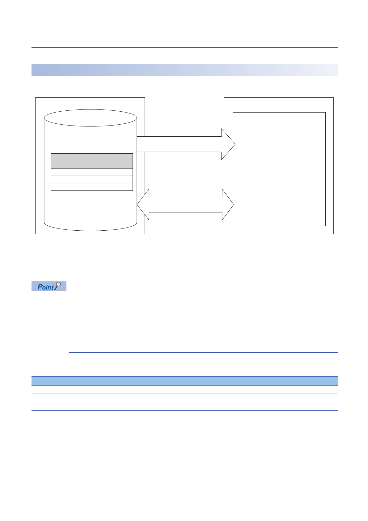
Label communication function
Label1
Label2
Label3
D0
D1
X0
C intelligent function module
(reference side)
CPU module
(Label definition side)
User program
Obtain an information of the corresponding
devices using specified label (Label1, Label2).
1. Execute the mdrGetLabelInfo function.
Label assignment information
Assignment target
(Device name)
Label name
Execute Reading/Writing for the device
corresponding to the label.
2. Execute the
mdrRandRLabel/mdrRandWLabel function.
Data can be read from/written to labels stored in a CPU module.
Label communication flow
1. Acquire label assignment information (device information) of the specified label with the MELSEC iQ-R series data link
function (mdrGetLabelInfo).
2. Read/write data from/to a device based on the acquired label assignment information (device information) by using each
MELSEC iQ-R series data link function (mdrRandRLabel/mdrRandWLabel).
• In the label communication, a CPU module can be accessed without changing a user program by acquiring
label assignment information again even if the label assignment information of the CPU module is changed.
• The label assignment information (device information) acquired by using the MELSEC iQ-R series data link
function (mdrGetLabelInfo) does not need to be acquired for each MELSEC iQ-R series data link function
(mdrRandRLabel/mdrRandWLabel) execution. However, if the label assignment information (device
information) stored in a CPU module is changed, acquire it again by using the MELSEC iQ-R series data
link function (mdrGetLabelInfo). (Otherwise, an error response is returned.)
■Function list
The following table shows the functions used for label communication.
Function name Description
mdrGetLabelInfo To acquire device information corresponding to label names.
mdrRandRLabel To read devices corresponding to labels randomly.
mdrRandWLabel To write devices corresponding to labels randomly.
16
1 FUNCTION
1.1 Program Related Function
Page 19

Accessible CPU modules
The following table shows the accessible CPU modules.
Product name Model name
Programmable controller CPU R00CPU, R01CPU, R02CPU, R04CPU, R08CPU, R16CPU, R32CPU, R120CPU
Process CPU R08PCPU, R16PCPU, R32PCPU, R120PCPU
Label types which can be referred to
The following table shows the label types that can be referred to from a C intelligent function module.
: Applicable, : Not applicable, : Not available
Label type "Access from External Device" is selected or not selected. Availability
Global label Selected
Unselected
Local label
System label
*1 The availability of the label differs depending on the device type assigned to the label.
For device type, refer to the following manual.
MELSEC iQ-R C Intelligent Function Module Programming Manual
For referring to a label, select "Access from External Device" in GX Works3.
(GX Works3 Operating Manual)
1
*1
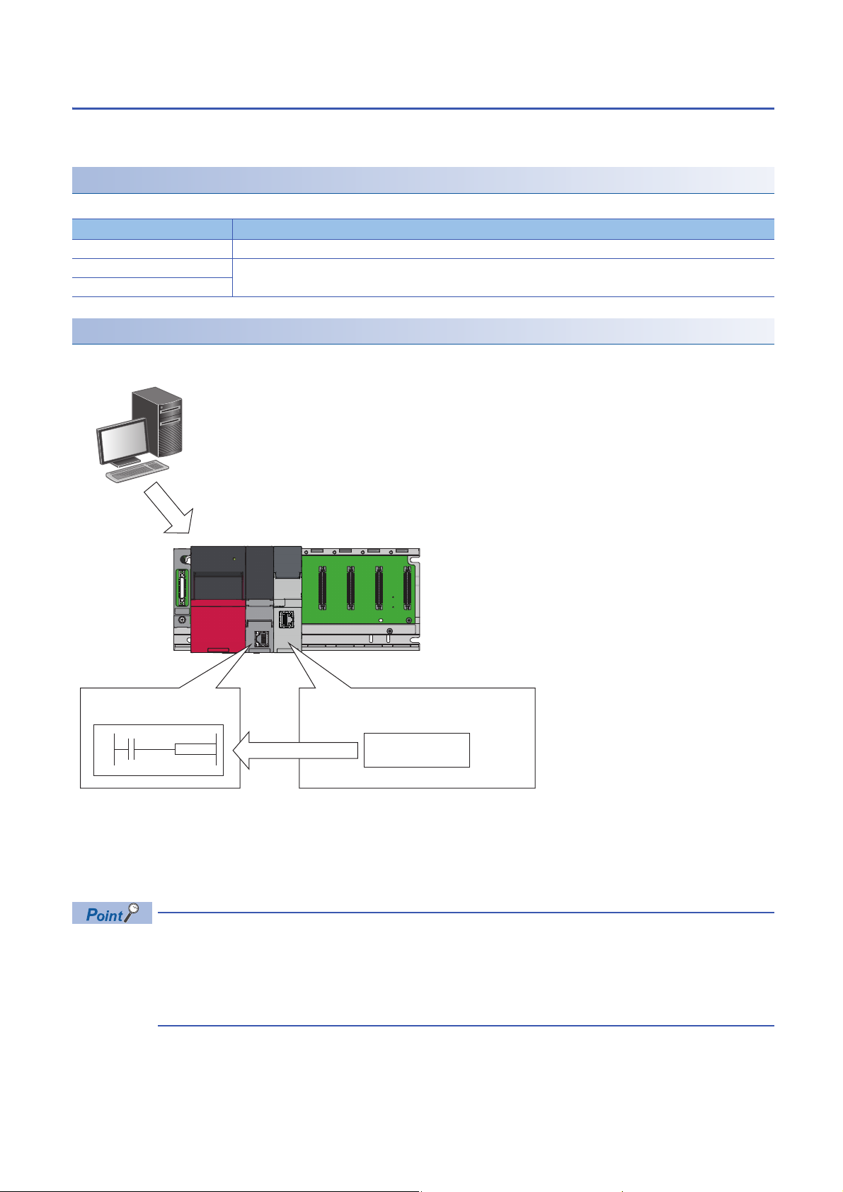
User program execution function from CPU module
A routine(user program), which is registered by C intelligent function module dedicated instruction
(CITL_EntryDedicatedInstFunc), can be executed on the CPU module using (G(P).CEXECUTE) dedicated instruction.
Function list
The following table shows the function used for executing a routine (user program) from a CPU module.
Function name Description
CITL_EntryDedicatedInstFunc To register a routine to be executed using the dedicated instruction (G(P).CEXECUTE).
■Execution procedure
This section explains the procedure for executing the user program.
1. Register a routine (user program) to be executed by C intelligent function module dedicated function
(CITL_EntryDedicatedInstFunc).
2. Execute the dedicated function (G(P).CEXECUTE) on the CPU module.
3. A registered routine (user program) is executed.
Dedicated instructions
For dedicated instructions, refer to the following section.
Page 85 Dedicated Instructions
1 FUNCTION
1.1 Program Related Function
17
Page 20
Interrupt function to a CPU module
I0
X10: ON = I0
1. Setting interrupt conditions
3. Interrupt program starts
2. Execute the
CITL_X_Out_Bit/CITL_X_Out_Word function
Module Parameter
Interrupt conditions
Interrupt request
When the interrupt condition set to an input signal (X) is satisfied, a C intelligent function module issues an interrupt request
for a CPU module. An interrupt program of the CPU module can be activated by the interrupt request.
Function list
The following table shows the functions used for interrupting a CPU module.
Function name Description
CITL_X_Out_Bit To write to an input signal (X) in bit (1-point) units.
CITL_X_Out_Word To write to an input signal (X) in word (16-point) units.
CITL_X_Out_Word_ISR
Interrupt procedure
Interrupt requests to the CPU module are executed by interrupt conditions set in the unit parameter.
1. Set interrupt conditions in the C intelligent function module using an engineering tool. (Page 49 Interrupt Setting)
2. When an interrupt condition is set at the time of C intelligent function module dedicated function execution
(CITL_X_Out_Bit/CITL_X_Out_Word), an interrupt request for the CPU module is executed.
3. Interrupt program of the CPU module is started by the interrupt request.
18
1 FUNCTION
1.1 Program Related Function
When "Leading Edge/Trailing Edge" is set in the "Interrupt Condition Setting", the first interrupt factor which
occurs during an interrupt program execution is recorded and the second or later ones are ignored. When
'trailing edge → leading edge' occurs during an interrupt program execution by leading edge, the second or
later interrupt programs are not executed. Therefore, ensure a sufficient interval between input ON and OFF.
(Same for 'trailing edge → leading edge → trailing edge)
Page 21
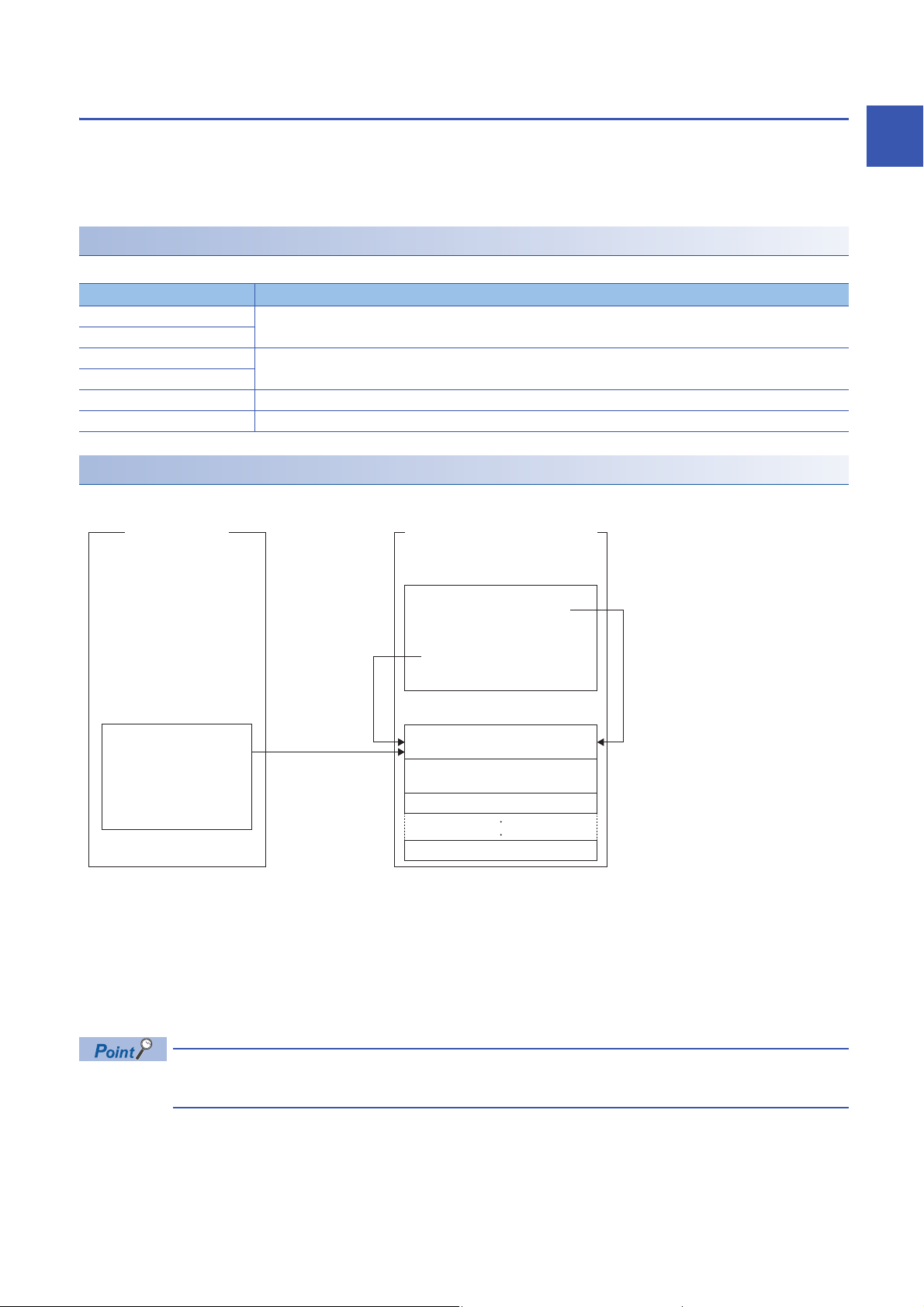
Interrupt function to a C intelligent function module
C intelligent function module
CPU module
User program
1. Execute the CITL_EntryYInt function
2. Execute the CITL_EnableYInt function
Register a
routine.
Enable a
routine.
User Interrupt Processing Table
Sequence program
Interrupt routine 1
(Interrupt program)
3. Output signal (Y) is
turned ON.
Interrupt routine 2
(Interrupt program)
(Empty)
(Empty)
When the output signal (Y) of the C intelligent function module is ON, the routine (user program) registered with the C
intelligent function module dedicated function (CITL_EntryYInt) can be executed as an interrupt routine (interrupt program).
A user program in a state of waiting for an output signal (Y) interrupt event notification can be restarted by using the C
intelligent function module dedicated function (CITL_WaitYEvent).
Function list
The following table shows the functions used for interrupting a C intelligent function module.
Function name Description
CITL_DisableYInt To disable the routine registered with the CITL_EntryYInt function.
CITL_DisableYInt_ISR
CITL_EnableYInt To enable the routine registered with the CITL_EntryYInt function.
CITL_EnableYInt_ISR
CITL_EntryYInt To register a routine to be called when an output signal (Y) interrupt occurs.
CITL_WaitYEvent To wait for the output signal (Y) interrupt event notification.
Interrupt procedure
■Executing interrupt routines
1
1. By using the C intelligent function module dedicated function (CITL_EntryYInt), register a routine (user program) to be
called as an interrupt routine (interrupt program) when an output signal (Y) of a C intelligent function module turns ON.
2. Enable the registered interrupt routine (interrupt program) by using the C intelligent function module dedicated function
(CITL_EnableYInt). If it is disabled, the interrupt routine (interrupt program) will not be executed.
3. When the output signal (Y) of a C intelligent function module turns ON, the interrupt routine (interrupt program) is
executed.
When an interrupt request is issued to the routine disabled with the C intelligent function module dedicated
function (CITL_DisableYInt), the interrupt request is ignored.
1 FUNCTION
1.1 Program Related Function
19
Page 22

■Restarting user programs
Precautions
C intelligent function module
CPU module
Sequence program User program
1. Execute the
CITL_WaitYEvent function
2. Interrupt event wait state
3. Output signal (Y) is
turned ON.
Restart
1. Execute the C intelligent function module dedicated function (CITL_WaitYEvent) while executing a user program.
2. The user program is placed into a state of waiting for an output signal (Y) interrupt event notification.
3. When the output signal (Y) of a C intelligent function module is turned ON, the user program is restarted.
The following shows the considerations when using C intelligent function module dedicated function (CITL_WaitYEvent).
■When an interrupt event has already been notified
When an interrupt event has already been notified at the time of executing the C intelligent function module dedicated function
(CITL_WaitYEvent), a user program restarts from a state of waiting for an interrupt event at the same time as the execution of
the function.
In addition, when multiple interrupt events have been notified to the same interrupt event number at the time of executing the
C intelligent function module dedicated function (CITL_WaitYEvent), a user program performs processing as a single interrupt
event notification.
■When using the function in multiple user programs
Do not specify a same interrupt event (output signal (Y) number) in multiple user programs.
Otherwise, a user program to which a specified interrupt event (output signal (Y) number) is notified will be undefined.
20
1 FUNCTION
1.1 Program Related Function
Page 23

Data analysis function
This function performs data analysis processing such as fast Fourier transform, digital filter operation, calculation of a cross
point between a wave and a specified value, and calculation of a standard deviation.
This function enables the detection of machining errors by monitoring current wave and the preventive maintenance of
devices by analyzing vibrations.
For data analysis functions and statistical analysis functions, refer to the following manual.
MELSEC iQ-R C Controller Module/C Intelligent Function Module Programming Manual (Data Analysis)
Function list
The following table shows the functions used for the data analysis function.
■Data analysis function
Function name Description
DANL_SetOpCondition To set operating conditions for data analysis.
DANL_GetOpCondition To acquire operating conditions for data analysis.
DANL_DigitalFilter To perform digital filter operation for the specified wave.
DANL_EnvelopeCalculation To calculate the envelope of the specified wave.
DANL_FFTSpectrum To perform spectrum calculation using fast Fourier transform (FFT) for the specified wave.
DANL_FindCrossPoint To calculate the number of cross points of the specified wave and a reference value for the number of cross points
specified to the maximum number of cross points.
DANL_Peak To calculate the peak values (maximum and minimum) of the specified wave.
DANL_RMS To calculate an RMS (root mean square) of the specified wave.
DANL_BoundCompareTest To compare the specified wave and a check value to check an upper/lower limit.
DANL_AryBoundCompareTest To compare the specified wave and a check value to check an upper/lower limit of the wave.
1
■Statistical analysis function
Function name Description
DANL_LeastSquare To calculate a coefficient and a constant of a polynomial, and a multiple correlation coefficient by using a least-squares
method for the specified array.
DANL_MovingAverage To calculate a moving average of the specified array.
DANL_StandardDeviation To calculate a standard deviation of the specified array.
DANL_Variance To calculate a variance of the specified array.
DANL_MTUnit To determine a unit space that is used in the MT method based on the specified normal data.
DANL_MTMahalanobisDistance To calculate a Mahalanobis distance of the specified input data.
DANL_MultipleRegression To calculate a coefficient, constant, and regression statistics for multiple regression analysis.
1 FUNCTION
1.1 Program Related Function
21
Page 24

Data analysis or statistical analysis using a CPU module
Using a dedicated instruction or a module FB, analysis processing can be performed on a C intelligent function module.
Dedicated instructions
For dedicated instructions, refer to the following section.
Page 85 Dedicated Instructions
Module FBs
For module FBs, refer to the following manual.
MELSEC iQ-R C Intelligent Function Module Function Block Reference
Processing flow for analyzing data
The following shows the processing flow for analyzing data when a dedicated instruction or a module FB is executed on a
CPU module.
1. A dedicated instruction or a module FB is executed on a CPU module.
2. An analysis processing is performed on the C intelligent function module.
3. After the completion of the process, the C intelligent function module returns the result to the CPU module.
22
1 FUNCTION
1.1 Program Related Function
Page 25

1.2 Ethernet Communication Function
Precautions
FTP function
The server function of FTP(File Transfer Protocol), which is a protocol used to transfer files with target devices, is supported.
The target device with FTP client function can access the files in the C intelligent function module.
File operation
The following operations can be performed for a file in a C intelligent function module from a target device with the FTP client
function.
■Reading file (Download)
Use this when storing a file in a C intelligent function module on the target device side.
■Writing files (Upload)
Use this when registering a file stored on the target device side to a C intelligent function module.
■Browsing and deleting files and folders
Use this when browsing and deleting a file and folder in a C intelligent function module from the target device side.
Using FTP function
For using the FTP function, the service/account needs to be set.
Page 33 Service/account setting function
1
Users for file transfer function can be restricted by using user information (account settings).
■Account setting
This shows account settings set prior to the shipment (Initial settings).
• Login name: target
• Password: password
To prevent unauthorized access, change the password when using the FTP function.
■Specifications of FTP client
For the specifications of the FTP client installed on the target device, refer to the manual of the target device.
■Operation while accessing file
Do not perform any of the following operations while accessing the file. The file may get damaged.
• Reset the CPU module, or turn the power OFF.
• Insert/remove an SD memory card.
■Reconnection after timeout
If a timeout error occurred during file transfer, the TCP connection will be closed (disconnected).
Log in to the C intelligent function module again with the FTP client before restarting the file transfer.
■File transmission time
The file transfer processing time will differ depending on the following causes.
• Load rate of Ethernet line (line congestion)
• Number of connections to be used simultaneously (processing of other connections)
• System Configuration
1 FUNCTION
1.2 Ethernet Communication Function
23
Page 26

■Number of simultaneous connections
• Up to 10 target devices (FTP client) can log in to a C intelligent function module. If connecting from the 11th FTP client in
the state where 10 target devices have logged in, an error will occur without establishing the connection.
• If UDP communication is performed during file transfer with FTP, an error such as timeout may occur. Either communicate
after the file transfer or communicate with TCP.
■Writing files
• Files with the read-only attribute and files that are locked from other devices/functions cannot be written. Doing so may
cause a write error.
• The write files cannot be transferred if the SD memory card is write-protected. Doing so may cause a write error.
■Deleting files
Determine the timing for deleting the files for the entire system including the C intelligent function module and peripheral
devices.
■If the password has been forgotten
Initialize the C intelligent function module. Password before the shipment (Initial settings) will be changed. (Page 29
Initialization function)
24
1 FUNCTION
1.2 Ethernet Communication Function
Page 27

Telnet function
Precautions
This function executes the Shell command with a Telnet tool in a personal computer without using CW Workbench for a TCP/
IP network. This allows simple remote debugging (such as task information display and memory dumping) of a C intelligent
function module.
Using Telnet function
For using the Telnet function, the service/account needs to be set.
Page 33 Service/account setting function
■Account setting
This shows account settings set prior to the shipment (Initial settings).
• Login name: target
• Password: password
To prevent unauthorized access, change the password when using the Telnet function.
■Available Shell commands
Shell commands of CW Workbench can be used. For details on the shell commands, refer to the manual of VxWorks.
■Number of connections
The same C intelligent function module cannot be connected by using multiple Telnet tools. Connect a Telnet tool to a C
intelligent function module on a 1:1 basis. When connecting another Telnet tool, make sure to close (disconnect) the Telnet
tool being connected.
1
■Shell command
Shell commands entered from the Telnet tool operate on task of priority 1.
Note the following when executing the command. System errors/stop (such as watchdog timer error) may occur in a C
intelligent function module.
• Make sure to check the command specifications before executing commands which occupy the CPU processing.
• For rebooting VxWorks, reset the CPU module, or turn the power OFF and ON. Do not reboot VxWorks by executing the
command (reboot) of VxWorks or pressing + .
• Before executing a command in which arguments are included, make sure to check the command specifications/argument
specifications. (When executed without specifying those arguments, with the result that 0 is specified to an argument.) Do
not execute the close command with no argument specified. By doing so, a resource that is reserved in the VxWorks
system will be closed. When a command that shows the status of the module, such as the show command, is executed, the
module will be in the interrupt-disabled state for a long period of time, and any processing called from an interrupt routine is
not executed. As a result, an interrupt which occurs at the fixed interval may be delayed.
■Message display on Shell
A message issued by VxWorks during Telnet connection may be displayed on Shell. For the message of VxWorks, refer to the
manual and help of VxWorks.
1 FUNCTION
1.2 Ethernet Communication Function
25
Page 28

■Timeout
When the line is disconnected during Telnet connection, it will take 30 seconds before Telnet connection (TCP) times out on
the C intelligent function module side. Telnet cannot be reconnected until it times out.
Timeout time can be changed by the command provided by VxWorks.
ipcom_sysvar_set("iptcp.KeepIdle","XX",1);
ipcom_sysvar_set("iptcp.KeepIntvl","YY",1);
ipcom_sysvar_set("iptcp.KeepCnt","ZZ",1);
ipcom_ipd_kill("iptelnets");
ipcom_ipd_start("iptelnets")
Timeout time = iptcp.KeepIdle value + (iptcp.KeepIntvl value × iptcp.KeepCnt value)
• iptcp.KeepIdle: Time from when the line is disconnected to the first retry
• iptcp.KeepIntvl: Interval between retries
• iptcp.KeepCnt: Number of retries
• XX, YY: Specify the time (in seconds). (When '0' is specified, no timeout will occur.)
• ZZ: Specify the number of retries.
The following shows the procedure to change the timeout time of a C intelligent function module in operation.
1. Establish a Telnet connection to a C intelligent function module with a Telnet tool.
2. Execute the commands given above from the Shell command of the Telnet tool and change the timeout time.
3. Reboot the Telnet server.
4. Close (disconnect) the Telnet connection.
5. Establish a Telnet connection to a C intelligent function module with a Telnet tool again.
To change the Telnet connection (TCP) timeout time while starting the C intelligent function module, follow the procedure
below.
1. Describe the commands given above in the script file (STARTUP.CMD).
2. Turn the power of the CPU module ON.
■If the Telnet password has been forgotten
Initialize the C intelligent function module. Password before the shipment (Initial settings) will be changed. (Page 29
Initialization function)
26
1 FUNCTION
1.2 Ethernet Communication Function
Page 29

1.3 RAS Function
Precautions
Program Monitoring (WDT) Function
This function monitors and detects errors on hardware and a user program by using the watchdog timer (WDT), an internal
timer of a C intelligent function module.
Program monitoring (WDT) type
■System watchdog timer
A timer to monitor the system of a C intelligent function module.
Use this to detect an error in hardware and system software.
■User watchdog timer
A timer to monitor a user program.
Use this to detect an error in a user program.
Monitoring time setting and reset
■System watchdog timer
The monitoring time of the system watchdog timer is 2000 ms (fixed value).
The system of a C intelligent function module resets it every cycle (2000 ms).
■User watchdog timer
Set a monitoring time for the user watchdog timer within the range of 100 ms to 10000 ms (in 10 ms units) by using the C
intelligent function module dedicated function (CITL_StartWDT).
Monitoring starts by executing the C intelligent function module dedicated function (CITL_StartWDT), and the monitoring time
is reset by executing the C intelligent function module dedicated function (CITL_ResetWDT).
1
Timeout of watchdog timer
When the watchdog timer times out, an error indicating that the monitoring time set in the watchdog timer setting has been
exceeded (watchdog timer error) occurs. If a system watchdog timer error occurs, the RUN LED turns OFF and the ERR LED
turns ON. If a user watchdog timer error occurs, the ERR LED starts flashing.
■System watchdog timer
In case of failure of a C intelligent function module hardware and interrupt program execution, timeout will occur as the system
processing has been suspended for a long time.
■User watchdog timer
If a user program cannot complete processing within the time specified by using the C intelligent function module dedicated
function (CITL_StartWDT), and also cannot reset by using the C intelligent function module dedicated function
(CITL_ResetWDT), a timeout will occur.
When using the following functions, a user watchdog timer error occurs easily since the CPU utilization by a system task with
high priority increases.
• Shell command
• Connection with CW Workbench and Wind River Workbench
• Mounting and unmounting an SD memory card
• File access
• Ethernet communication
• NFS server communication
1 FUNCTION
1.3 RAS Function
27
Page 30

Error history function
Errors occurred in a C intelligent function module are stored in maximum 16 buffer memory as a history. If a major/moderate
error occurs, even if new errors have occurred, the history is not updated.
Event history function
The errors occurred in a C intelligent function module and operations executed are sampled in the CPU module as an event
information.
Event information occurred in a C intelligent function module is sampled and held in the data memory or an SD memory card
in a CPU module.
An event information sampled by CPU module can be displayed by an engineering tool and the occurrence history can be
checked chronologically.
Setting method
Event history function can be set from the event history setting screen of an engineering tool.
For the setting method, refer to the following section.
MELSEC iQ-R CPU Module User's Manual (Application)
■Checking an event history
Can be checked from an engineering tool.
For details on the operating procedures and how to read the displayed information, refer to the following manual.
GX Works3 Operating Manual
Self-diagnostic function
Self-diagnostics test is performed to check the hardware of a C intelligent function module.
Self-diagnostics test is as follows.
• Automatic Hardware Test (Page 54 Automatic hardware test)
• Hardware test for LED check (Page 55 Hardware test for LED check)
28
1 FUNCTION
1.3 RAS Function
Page 31

Initialization function
Initialization and script of the C intelligent function module can be stopped.
When the initialization is in progress, the value of buffer memory cannot be checked by an engineering tool.
Types of initialization
■Stop script setting
Execution of a script file (STARTUP.CMD), which is registered in standard ROM, is stopped.
*1 Registration will be cancelled by renaming the script file name with "STARTUP.BAK".
■Module initialization setting
Service/account settings are initialized (factory default status) by initializing the standard ROM.
*1
Initialization
1. Change to "Stop Script File Setting" or "Module Initialization Setting" in [Basic Settings] [Various Operations Settings]
[Mode Settings] in the module parameter of the C intelligent function module in the parameter setting of an
engineering tool. (Page 45 Basic Setting).
2. Set the CPU module to the STOP state, and write the parameters.
3. Reset the CPU module.
4. After resetting the CPU module, initialization is automatically executed.
Status RUN LED status ERR LED status
Initialization in progress Flashing (low-speed) OFF
Initialization complete Normal completion ON OFF
Abnormal completion ON ON
1
5. When the initialization completed normally, select "Online" in [Basic Settings] [Various Operations Settings] [Mode
Settings] in the module parameter of the C intelligent function module in the parameter setting of an engineering tool to
reset the CPU module.
6. At an abnormal completion, check whether measures are taken to reduce noise of the programmable controller system
and execute the automatic hardware test again. If the process is completed abnormally again, there may be a hardware
failure in the C intelligent function module. Please consult your local Mitsubishi representative. While removing the
module, do not use an electric screwdriver. Remove the module when the module fixing screws are in fully loosened
state.
1 FUNCTION
1.3 RAS Function
29
Page 32

1.4 Security Function
This function prevents assets stored in a C intelligent function module from being stolen, falsified, operated incorrectly, and
executed improperly due to unauthorized access from a third party.
The security function is one of the methods for preventing unauthorized access (such as program or data
corruption) from an external device. However, this function does not prevent unauthorized access completely.
Incorporate measures other than this function if the programmable controller system's safety must be
maintained against unauthorized access from an external device. Mitsubishi Electric Corporation cannot be
held responsible for any system problems that may occur from unauthorized access.
Examples of measures for unauthorized access are shown below.
• Install a firewall.
• Install a personal computer as a relay station, and control the relay of send/receive data with an application
program.
• Install an external device for which the access rights can be controlled as a relay station. (For details on the
external devices for which access rights can be controlled, consult the network provider or equipment
dealer.)
Individual identification information read function
The individual identification information of a C intelligent function module can be read with the C intelligent function module
dedicated function (CITL_GetIDInfo). By implementing an activation function with a user program, a user program, which
does not run in C intelligent function modules with other individual identification information, can be created.
For C intelligent function module dedicated functions, refer to the following manual.
MELSEC iQ-R C Intelligent Function Module Programming Manual
30
1 FUNCTION
1.4 Security Function
Page 33

File access restriction function
S R H
S
R
H
Indicates the hidden file attribute is specified.
Indicates the hidden file attribute is not specified.
Indicates the system file attribute is specified.
Indicates the system file attribute is not specified.
Indicates the read-only attribute is specified.
Indicates the read-only attribute is not specified.
Blank
Blank
Blank
A file attribute can be set for the files stored in the following types of memory. By setting a file attribute, access to a target file
can be restricted, and falsification by an unauthorized user and data leakage to outside can be prevented.
• Standard ROM
• SD memory card
• When an SD memory card is inserted to a peripheral device other than a C intelligent function module (such
as a personal computer), files to which the access restriction is set can be operated. If the access restriction
is set for the file in the SD memory card, take appropriate measures so that the SD memory card cannot be
removed from the C intelligent function module at will.
• Access restrictions cannot be set for the folder.
File access restriction function setting
Change a file attribute handled in a C intelligent function module by using the attrib() command. A security password is
required to change a file attribute.
For details on the attrib() command, refer to the manual of VxWorks.
■Setting file attribute
Set a file attribute to a file to be restricted by using the attrib() command.
The file attributes that can be handled in a C intelligent function module are as follows.
Attribute Description
S System file attribute File attributions can be prohibited.
R Read-only attribute
H Hidden file attribute
*1
*2
File deletion and data write can be prohibited.
A file is not listed by using the ls command and it is not displayed at FTP connection.
1
*1 This attribute is not supported by the file access restriction function. However, if it is set, file deletion and file write can be prohibited.
*2 When the file is opened by specifying the file name, file operations can be performed. In order to prohibit the file operations, ensure to
set the system file attribute.
■Checking file attribute
A file attribute which is set can be checked by using the attrib() command.
1 FUNCTION
1.4 Security Function
31
Page 34

Checking file access restriction status
Precautions
File access restriction status can be checked by executing the Shell command or the C intelligent function module dedicated
function (CITL_GetFileSecurity).
File access restriction status cannot be checked by using the script file (STARTUP.CMD).
Canceling/re-setting file access restriction
Change the file access restriction status by using the Shell command, the script file (STARTUP.CMD), or a user program. The
security password set with an engineering tool is required.
■Changing system file attribute
For operating a file with a system file attribute attached, cancel the file access restriction temporarily with the C intelligent
function module dedicated function (CITL_ChangeFileSecurity). The canceled setting can be set again by setting the file
access restriction with the C intelligent function module dedicated function (CITL_ChangeFileSecurity) or resetting the C
intelligent function module.
• When accessing a file to which a system file attribute is attached in the script file "STARTUP.CMD", cancel
the access restriction in the script file (STARTUP.CMD). Again, add the system file attribute to the script file
(STARTUP.CMD) in order to prevent the leakage of the password.
• Do not use the files with the system file attribute attached in the script file (STARTUP.CMD) in an SD
memory card in order to prevent the leakage of password.
■When maintaining the safety against unauthorized access from external parties
To maintain the safety of a programmable controller system against unauthorized access from external parties, take
appropriate measures. Note the following when setting a security password to prevent the leakage of the security password.
• Avoid settings with only simple alphanumeric characters.
• Set a complex password with symbols.
■Settable characters for a security password
Characters that can be set are single byte alphanumeric characters and symbols. (Security password is case-sensitive.)
■If the security password has been forgotten
Initialize the C intelligent function module. (Page 29 Initialization function)
32
1 FUNCTION
1.4 Security Function
Page 35

Service/account setting function
Window
Displayed items
Set the services, account, and security password for a C intelligent function module.
By restricting the services and setting an account, unauthorized access from other users can be prevented.
Security password is required to change the service and account settings.
[Tool] [Module Tool List] [Information Module] [Service/account setting]
1
Item Description Setting Range
Service Settings Telnet A service to use a Telnet. • Enable
FTP A service to use an FTP.
WDB A service to connect CW Workbench.
DHCP A service to use a function which assigns the network
settings automatically.
MELSEC iQ-R series data link
function
Memory card access A service to access the memory card.
Memory card script execution A service to use the script file stored in the memory card.
Security password
settings
Account setting Login Name Set the account log in name. 1 to 12 characters (single byte
*1 If the password setting is not entered (blank), it does not change from the current password.
Password Setting
Password Setting
*1
*1
A service to use MELSEC iQ-R series data link functions.
Set a security password. 8 to 16 characters
Set the account password. 8 to 32 characters
• Disable
(Default: Enable)
(Default: password)
alphanumeric characters)
(Default: target)
(Default: password)
Usable character string for password setting
The following table shows the usable characters in the password setting.
Item Description
Character ASCII character string (Alphanumeric characters and special characters)
Usable special characters for password setting is as follows.
• `, ~, !, @, #, $, %, ^, &, *, (, ), _, +, -, =, {, }, |, \, :, ", ;, ', <, >, ?, ,, ., /, [, ], space
*2
*1
*1 The password is case-sensitive.
*2 Special characters (|, ,, space) cannot be used in the password setting of the account settings.
1 FUNCTION
1.4 Security Function
33
Page 36

IP filter function
Precautions
IP address: 192.168.3.15 IP address: 192.168.3.20 IP address: 192.168.3.25
Pass
Pass Block
IP filter function
Target IP Address (Pass)
IP address: 192.168.3.10 to 192.168.3.30
IP Address to Exclude (Block)
IP address: 192.168.3.25
C intelligent function module
Access from an illegal IP address is prevented by identifying the IP address of communication target.
There are two IP filter functions.
Allow function: Allows access only from the specified IP addresses.
Deny function: Denies access only from the specified IP addresses.
Setting method
1. Set the IP address to be allowed or denied in [Application Setting] [Security] "IP Filter Setting" in the module
parameter of the C intelligent function module in the parameter setting of an engineering tool. (Page 47 Application
Setting)
2. Set the CPU module to the STOP state, and write the parameters.
3. Reset the CPU module.
If there is a proxy server on the LAN, block the IP address of the proxy server. Otherwise, the access from the personal
computers that can access the proxy server cannot be prevented.
34
1 FUNCTION
1.4 Security Function
Page 37

1.5 Time Synchronization Function
Ex.
Ex.
500ms 500ms 500ms 500ms 500ms 500ms 500ms
(1) (2) (3) (4)
Time
synchronization
Time
synchronization
Time
synchronization
Time
synchronization
Time
synchronization
Time
01:59:59
01:59:59
02:00:00
03:00:00
02:00:01
03:00:01
Disabled
Enabled
(Daylight saving time) (Daylight saving time)
Start
00:59:59
01:00:00 01:00:01
01:00:00
01:59:59
01:00:01
Disabled
Enabled
(Daylight saving time)
End
The time synchronization function synchronizes the time in a C intelligent function module with the CPU module time (in
multiple CPU system, CPU No. 1).
Time synchronization timing
Timing of time synchronization is as follows.
• When the power is turned OFF and ON
• When the CPU module is reset
• Every 500 ms
• When the C intelligent function module dedicated function (CITL_SyncTime) is executed
*1 The operating status of time synchronization can be set with the C intelligent function module dedicated function
(CITL_SetSyncTimeStatus).
(1) The power is turned OFF and ON, or the CPU module is reset.
(2) The C intelligent function module dedicated function (CITL_SetSyncTimeStatus) is executed. (Synchronization is stopped.)
(3) When the C intelligent function module dedicated function (CITL_SyncTime) is executed.
(4) The C intelligent function module dedicated function (CITL_SetSyncTimeStatus) is executed. (Synchronization is started.)
*1
1
Daylight saving time
If daylight saving time is set in the CPU module, the clock will be set ahead by 1 hour when the daylight saving time starts, and
it will be set back to the original time when the daylight saving time ends.
The following shows an example of daylight saving setting time.
If the daylight saving time starts from 02:00
The clock will be set ahead by 1 hour at the start time.
If the daylight saving time ends at 02.00
The clock will be set back to the original time at the end time.
1 FUNCTION
1.5 Time Synchronization Function
35
Page 38

Operation for time synchronization
Precautions
When a time synchronization process is executed to the CPU module, the time in a C intelligent function module is changed.
Therefore, the time in the C intelligent function module may change significantly.
Since there is inaccuracy in the clock element in CPU module and C intelligent function module, the time may be moved
slightly forward or backward when the time is synchronized.
• Before using the C intelligent function module, set the clock data of CPU module. For the time data settings, refer to the
manual of the CPU module used.
• There is inaccuracy in the clock data of the CPU module used by C intelligent function module.
For the time data accuracy, refer to the user's manual of the CPU module used.
• When a C intelligent function module acquires the clock data in a CPU module, a maximum of one second of delay occurs
as the transfer time.
• A time zone is not required to be set for the time synchronization function of a C intelligent function module because the
clock data follows the time zone set in a CPU module. When specifying a time zone, set with a CPU module.
36
1 FUNCTION
1.5 Time Synchronization Function
Page 39

1.6 Sampling Function
0 END 0 END 0 END 0 END 0 END
Sequence scan time Sequence scan time Sequence scan time Sequence scan time Sequence scan time
Step
END processing END processing END processing END processing END processing
Sampling Sampling Sampling Sampling Sampling
This function samples target data from a CPU module.
• To sample data in each sequence scan, a CPU module supporting the sequence scan synchronization
sampling function is required.
• Data sampling in each sequence scan of a C intelligent function module is a best effort function. Since the
processing time varies depending on the setting and the status of other devices, this function may not
perform at the set sampling interval. Run the system by fully verifying the processing time of each function
when constructing it.
Data sampling in sequence scan
This function samples target data by synchronizing with a sequence scan from a control CPU module by using the sequence
scan synchronization sampling function of a control CPU module.
It also transfers device values to a C intelligent function module at the END processing of each scan in a control CPU module,
then stores them in the temporary area in the module. The device values stored in the temporary area can be acquired with a
C intelligent function module dedicated function.
For the sequence scan synchronization sampling function, refer to the following manual.
MELSEC iQ-R CPU Module User's Manual (Application)
1
■Timing of data sampling in each sequence scan
Target data is sampled for each sequence scan time of a CPU module.
When a CPU module is stopped, target data is not sampled.
At the time of data sampling in each sequence scan, scan time increases due to transfer from a CPU module to a C intelligent
function module.
For the influence on the sequence scan time, refer to the following manual.
MELSEC iQ-R CPU Module User's Manual (Application)
■Temporary area at the time of data sampling
When executing the C intelligent function module dedicated function (CITL_SetCollectData), the temporary area is reserved
in the memory with the following formula.
The reserved temporary area is released when executing the C intelligent function module dedicated function
(CITL_SetCollectData) again.
• Temporary area size: Number of retainable records × (Header information size + (Number of sampled points × 2 bytes))
The size of the temporary area varies depending on the number of sampling points and the number of retainable records.
*1 A record refers to data to be sampled in one sequence scan.
*1
1 FUNCTION
1.6 Sampling Function
37
Page 40

■Data sampling measurement time
The following shows the sequence scan time in which data can be sampled in each sequence scan.
However, since measurement time varies depending on the following external factors, the values in the following table are
only a guide when using the sampling function.
• Sequence scan time
• Network status
• Operating status of a user program
• Access status to a CPU module from a peripheral device and another intelligent function module
Item Number of device points
16 64 256 1024 4096 8192 16384 32768
Sampling rate [ms] 0.50.50.5135918
Data sampling flow
The following shows the flow of data sampling in each sequence scan.
■Function list
The following table shows the functions used for data sampling in each sequence scan.
Function name Description
CITL_GetCollectData To acquire data sampled in data sampling in each sequence scan.
CITL_SetCollectData To set data to be sampled in data sampling in each sequence scan.
CITL_StartCollectData To start data sampling in each sequence scan.
CITL_StopCollectData To stop data sampling in each sequence scan.
CITL_WaitCollectDataRecvEvent To wait for data to be sampled in data sampling in each sequence scan.
■Sampling data by polling
Target data is acquired from the temporary area of a C intelligent function module at a cycle set by a user.
However, if the execution cycle of the C intelligent function module dedicated function (CITL_GetCollectData) is too long, data
may be missing. Create a user program by reference to the sampling timing specified with the dedicated function. (Page
40 Free space in the temporary area)
1. Set target data to be sampled with the C intelligent function module dedicated function (CITL_SetCollectData).
2. Start data sampling in each sequence scan with the C intelligent function module dedicated function
(CITL_StartCollectData).
3. Acquire the target data from the temporary area of a C intelligent function module with the C intelligent function module
dedicated function (CITL_GetCollectData).
4. To acquire the next target data, execute the C intelligent function module dedicated function (CITL_GetCollectData)
again.
38
1 FUNCTION
1.6 Sampling Function
Page 41

■Sampling data by waiting for data to be sampled
Precautions
Target data is acquired from the temporary area of a C intelligent function module at the timing when data for the specified
number of records is stored in the temporary area with the C intelligent function module dedicated function
(CITL_WaitCollectDataRecvEvent).
1. Set target data with the C intelligent function module dedicated function (CITL_SetCollectData).
2. Start data sampling in each sequence scan with the C intelligent function module dedicated function
(CITL_StartCollectData).
3. Wait for data for the specified number of records to be sampled with the C intelligent function module dedicated function
(CITL_WaitCollectDataRecvEvent).
4. Acquire the target data from the temporary area of a C intelligent function module with the C intelligent function module
dedicated function (CITL_GetCollectData).
5. To acquire the next target data, execute the C intelligent function module dedicated function
(CITL_WaitCollectDataRecvEvent) again, and acquire the target data with the C intelligent function module dedicated
function (CITL_GetCollectData).
■Changing target data (re-registration)
When changing target data for data sampling in each sequence scan, data sampling needs to be stopped once.
Change target data after stopping data sampling.
1. Stop data sampling with the C intelligent function module dedicated function (CITL_StopCollectData).
2. Set target data with the C intelligent function module dedicated function (CITL_SetCollectData).
1
If CPU parameters of a control CPU module are changed during data sampling in each sequence scan, data sampling is
stopped. Since the assignment of devices may be changed due to the change of CPU parameters, set target data with the C
intelligent function module dedicated function (CITL_SetCollectData) again when restarting data sampling.
1 FUNCTION
1.6 Sampling Function
39
Page 42

Sampling timing of target data
To sample target data without missing, the free space needs to be created in the temporary area by executing the C intelligent
function module dedicated function (CITL_GetCollectData) and acquiring sampled data stored in the temporary area.
For the execution interval of the C intelligent function module dedicated function (CITL_GetCollectData), set an interval
optimal to the system within a value obtained by dividing 'the time when the space in the temporary area is full' by 2.
When the number of retainable records is extremely small, the space in the temporary area may be full even if
the execution timing of the C intelligent function module dedicated function (CITL_GetCollectData) is set to
the maximum value. Create a user program to periodically execute the C intelligent function module dedicated
function (CITL_GetCollectData) before the space in the temporary area is full.
■Free space in the temporary area
The temporary area of a C intelligent function module is reserved in the memory when executing the C intelligent function
module dedicated function (CITL_SetCollectData), and the space will be full at the time calculated with the following formula.
When the space in the temporary area is full, data will not be sampled after that and data will be missing.
• Time: Number of retainable records × Sequence scan time
Data missing
Data missing is that the sampled data is not continuous.
Data is missing in the following cases:
Item Description
Sampling failure • Data sampling in each sequence scan fails because it cannot catch up with the sampling interval
• The temporary area of a C intelligent function module is full with stored data
Module operation • The operating status of a control CPU module is switched from STOP to RUN at the time of data sampling in each
sequence scan
■Checking data missing
Data missing can be checked by the following methods:
• Buffer memory (data missing status)
• Header information (index and data missing status)
*1 When executing the C intelligent function module dedicated function (CITL_StopCollectData), the data missing status in the buffer
memory is initialized.
*1
40
1 FUNCTION
1.6 Sampling Function
Page 43

Data structure of target data
2017/1/1
12:00:00.0000
2017/1/1
12:00:00.0100
2017/1/1
12:00:00.0200
1
2
3
0
0
0
2017/1/1
12:01:45.5200
m0
~
~
~
~
(1) (2)
1
3
5
3
6
9
nn
The following shows the data structure of target data.
Item Description
(1) Header
information
(2) Target data Sampled data (start) Target data sampled in data sampling in each sequence scan
Index Indicates the sequential serial number of sampled data. (0 to 4294967295)
A numerical value counted up in ascending order starting from 1 is output. When it exceeds
the upper limit 4294967295, it counts up again from 0.
When data is missing, an index is assigned again from a record after data is missing. (It
counts up again from 1.)
Date and time Indicates the time of a C intelligent function module when data is sampled.
Data missing status Indicates the data missing status.
Data is missing between a record in which the data is missing and the previous record.
• 0: Data is not missing
• 1: Data is missing
Sampled data (end)
1
■Header information
Data is output continuously in order from an index, a date and time, and the data missing status to the header information.
For header information, data to be output can be specified with the C intelligent function module dedicated function
(CITL_SetCollectData).
■Record size
The size of a record to be acquired can be checked with the C intelligent function module dedicated function
(CITL_SetCollectData).
1 record size is the total size of header information and target data.
Item Description
Header information The size of header information is the total of a data size to be output.
Target data The size of target data can be calculated with the following formula. (Word)
The calculating formula when outputting an index, a date and time, and the data missing status is as follows:
• Header information size = Index (2 words) + Date and time (4 words) + Data missing status (1 word)
• Target data size = Number of bit devices + Number of word devices + (Number of double word devices × 2)
1 FUNCTION
1.6 Sampling Function
41
Page 44

Target data
Precautions
The following shows the data that can be sampled at the time of data sampling in each sequence scan.
■Data type
Target data can be sampled as a data type in the following table:
Data type Number of device points
Bit 1 point
Word 1 point
Double word 2 points
■Number of settings
Target data can be set up to 32768 points.
Note that the number of points that can be sampled for one control CPU module must not be exceeded.
MELSEC iQ-R CPU Module User's Manual (Application)
When multiple intelligent function modules use the sequence scan synchronization sampling function, note the total number of
points for target data. If it exceeds the number of points that can be sampled, an error may occur in registration processing of
an intelligent function module registered later.
42
1 FUNCTION
1.6 Sampling Function
Page 45

■Device list
The file registers for each local device and program in which the program name is specified cannot be accessed.
Bit specified devices and digit specified devices cannot be specified.
Item Description
Device Special relay (SM)
Special register (SD)
Input relay (X)
Output relay (Y)
Internal relay (M)
Latch relay (L)
Annunciator (F)
Edge relay (V)
Link relay (B)
Data register (D)
Link register (W)
Timer Contact (TS)
Coil (TC)
Current value (T/TN)
Long timer Contact (LTS)
Coil (LTC)
Current value (LT/LTN)
Counter Contact (CS)
Coil (CC)
Current value (C/CN)
Long counter Contact (LCS)
Coil (LCC)
Current value (LC/LCN)
Retentive timer Contact (STS)
Coil (STC)
Current value (ST/STN)
Long retentive timer Contact (LSTS)
Coil (LSTC)
Current value (LST/LSTN)
Link special relay (SB)
Link special register (SW)
Index register (Z)
Long index register (LZ)
(ZR)
*2
*2
File register (R)
Refresh data register (RD)
*1
*1
*1
*1
*1
*1
1
*1 Either of the device names can be specified.
*2 When accessing out of the range of the file register (R/ZR) area, the value of -1(FFFFH) is read.
1 FUNCTION
1.6 Sampling Function
43
Page 46

2 PARAMETER SETTING
Set various operations in parameters with an engineering tool.
2.1 Parameter Setting Procedure
The parameter setting procedure when C intelligent function module is used is shown below.
1. Add a C intelligent function module to an engineering tool.
[Navigation window] [Parameter] right-click [Module Information] [Add New Module]
2. There are four types of Parameter settings: Basic setting, Application setting, Interrupt setting, and Refresh setting.
Select the parameter setting from the tree in the following screen.
[Navigation window] [Parameter] [Module Information] [RD55UP06-V]
3. Write the settings to the CPU module with an engineering tool.
[Online] [Write to PLC]
4. Apply the settings by resetting the CPU module, or turning the power OFF and ON.
44
2 PARAMETER SETTING
2.1 Parameter Setting Procedure
Page 47

2.2 Basic Setting
Window
Displayed items
Set mode settings and own node settings.
2
Item Description Setting Range
Mode Settings Select an operation mode of a C intelligent function module.
• Online: Normal operation mode.
• Stop Script Setting: The registered script file stops being executed.
• Module Initialization Setting: The standard ROM is formatted.
• Automatic Hardware Test: The tests related to the H/W of the C intelligent function
module such as ROM, RAM and Ethernet are performed.
• Hardware test for LED check: The LED test of the C intelligent function module is
executed.
Own Node
Setting
IP Address
Setting
Set the IP address, subnet mask, and default gateway of the own node.
The IP address setting screen appears by double-clicking a cell of IP address setting.
•Online
• Stop Script File Setting
• Module Initialization Setting
• Automatic H/W Test
•LED H/W Test
(Default: Online)
Page 46 IP address setting
screen
2 PARAMETER SETTING
2.2 Basic Setting
45
Page 48

IP address setting screen
Set the IP address of the own node.
Item Description Setting Range
IP Address Set the IP address of the own node.
Ensure that the own node and the external device to be communicated with have the
same class and subnet address.
Set the IP address in the range of class A/B/C.
If IP address is not set, the module operates as if 192.168.3.3 is set.
The setting values of the IP address differ according to the setting values of the
Subnet mask. Take note of the following points to set the IP Address and the Subnet
Mask setting.
• Bits of the host address (parts of the subnet mask that carry 0) of the IP address
are not all set to 0 or 1.
• Bits of the network address (parts of the subnet mask that carry 1) of the IP
address are not all set to 0 or 1.
Subnet mask Set the subnet mask of the own node.
This setting is used to determine how many upper bits among the IP addresses are
used in the network address. The network address is then used to identify a network.
For example, set '255.255.255.0' when the upper 24 bits of an IP address are
assigned to the subnet mask.
The setting values of the IP address differ according to the setting values of the
Subnet mask. Take note of the following points to set the IP Address and the Subnet
Mask setting.
• Bits of the host address (parts of the subnet mask that carry 0) of the IP address
are not all set to 0 or 1.
• Bits of the network address (parts of the subnet mask that carry 1) of the IP
address are not all set to 0 or 1.
Default gateway Set the IP address of the default gateway (the device which the own node passes
through to access a device of another network).
Set the subnet address of default gateway so that it is the same as the one of the
host station.
• Blank (IP address not set)
• 0.0.0.1 to 223.255.255.254
(Default: blank)
• Blank
• 128.0.0.0 to 255.255.255.252
(Default: blank)
• Blank
• 0.0.0.1 to 223.255.255.254
(Default: blank)
46
2 PARAMETER SETTING
2.2 Basic Setting
Page 49

2.3 Application Setting
Window
Displayed items
Set the target IP address.
2
Item Description Setting Range
IP filter setting IP Filter Set whether to use the IP filter function. • Not Use
•Use
(Default: Not Used)
Access From IP Address
Below
IP Filter Detail Setting Set the IP addresses to be allowed/denied.
Set whether to allow/deny the access from the specified IP addresses. • Pass
•Block
Do not include loopback address (127.0.0.1) in the target IP address.
The IP Filter Detail Setting screen appears by double-clicking a cell of IP filter
detailed setting.
Page 48 IP address
setting screen to be excluded
2 PARAMETER SETTING
2.3 Application Setting
47
Page 50

IP address setting screen to be excluded
Window
Displayed items
Set the target IP address and IP address to be excluded.
Item Description Setting Range
Target IP Address Set the IP addresses to be allowed/denied. 0.0.0.1 to 223.255.255.254
(Default: blank)
IP Address to Exclude Set the IP addresses blocked or not allowed by excluding from the IP addresses
to which range is set.
0.0.0.1 to 223.255.255.254
(Default: blank)
48
2 PARAMETER SETTING
2.3 Application Setting
Page 51

2.4 Interrupt Setting
Window
Displayed items
Set interrupt operation settings, interrupt conditions, and interrupt pointer.
2
Item Description Setting Range
Input/Interrupt Operation Setting Set whether to operate in input or interrupt. • Input Setting
Interrupt Condition Setting Set conditions for interrupt occurrence factor.
"Input/Interrupt operation settings" are valid only when "interrupt" occurs.
Interrupt Pointer Specify the interrupt pointer number which is activated when the interrupt factor is
detected.
Example: Set 'I50' to specify interrupt pointer I50.
• Interrupt Setting
(Default: Input Setting)
• Leading Edge
• Trailing Edge
• Leading Edge/Trailing Edge
(Default: Leading Edge)
I0 to I15, I50 to I1023
(Default: blank)
■Interrupt pointer
Specify an interrupt pointer that operates when interrupt factor is detected.
For details of interrupt point, refer to the following section.
MELSEC iQ-R CPU Module User's Manual (Application)
2 PARAMETER SETTING
2.4 Interrupt Setting
49
Page 52

2.5 Refresh Setting
Window
Displayed items
Set the refresh timing as per specified refresh target.
Setting Value Description
At the Execution Time of END
Instruction
At the execution time of specified
program
At END processing of CPU module, settings are refreshed.
When executing a specified program in the "group [n]", settings are refreshed.
50
2 PARAMETER SETTING
2.5 Refresh Setting
Page 53

3 TROUBLESHOOTING
This chapter explains the errors which may occur when using an C intelligent function module and the troubleshooting.
3.1 Checking Method for Error Descriptions
The following are the methods to check error descriptions.
Checking method Description
System monitor of an engineering tool Error codes can be checked by the system monitor of an engineering tool.
Buffer memory Error codes can be checked in the following buffer memory.
Check with a C intelligent function module dedicated
function
• If multiple errors occur at the same time, take corrective action for the errors in chronological order.
• If a user program is incorrect, the accurate error code may not be output. If the error is not cleared even
after taking corrective action, review the user program.
3.2 Error Type
Page 79 Current error area (Un\G140 to 147)
Page 80 Error log area (Un\G150 to 311)
Error codes can be checked with the C intelligent function module dedicated function
(CITL_GetErrInfo).
3
There are two types of errors of a C intelligent function module as follows:
Error Type Lighting
status of
ERR LED
Module minor error ON Input signal (X) and buffer memory output continues. After taking corrective actions according to the error
Module major error or
moderate error
Flashing Input signal (X) and buffer memory output stops.
Module Status Corrective action
code content, turn the ERR LED OFF by any of the
following operations.
• Turning ON the error clear request (YF)
• Cleaning error from an engineering tool
• Clearing error with C intelligent function module
dedicated function (CITL_ClearError)
• Resetting the CPU module, or turning the power
OFF and ON
3 TROUBLESHOOTING
3.1 Checking Method for Error Descriptions
51
Page 54

3.3 Checking Module Status
Window
Displayed items
The following functions can be used in the "Module Diagnostics" screen of an engineering tool.
Function Purpose
Error Information To display the description of an error currently occurred.
The history of an error detected in a C intelligent function module and an executed operation can be
checked by clicking the [Event History] button.
Module Information List To display the information of each status of a C intelligent function module.
Error information
The currently occurred error and its corrective action can be checked.
Item Description
Detailed Information Up to three details of each error is displayed.
Cause The detail of an error cause is displayed.
Corrective Action A corrective action for an error is displayed.
52
3 TROUBLESHOOTING
3.3 Checking Module Status
Page 55

Module information list
Window
Displayed items
The information for each status of a C intelligent function module can be checked by switching to the [Module Information List]
tab.
3
■LED information
Item Description
RUN The LED status or the self-diagnostic status is displayed.
• ON: In operation
• Flashing (high-speed): Checking (waiting for the online module change confirmation)
• Flashing (low-speed): Initializing (including the execution of the script file, "STARTUP.CMD")
• OFF: Watchdog timer error (hardware failure)
• Performing the automatic hardware test (Page 54 Automatic hardware test)
• Performing the hardware test for LED check (Page 55 Hardware test for LED check)
ERR The ERR LED status or the self-diagnostic status is displayed.
• ON: Module minor error or watchdog timer error (hardware failure)
• Flashing: Module major error or moderate error
• OFF: In normal status
• Performing the automatic hardware test (Page 54 Automatic hardware test)
• Performing the hardware test for LED check (Page 55 Hardware test for LED check)
USER The USER LED status is displayed.
CARD RDY The CARD RDY LED status or the self-diagnostic status is displayed.
• ON/OFF/Flashing: Controlled by a user program
• Performing the automatic hardware test (Page 54 Automatic hardware test)
• Performing the hardware test for LED check (Page 55 Hardware test for LED check)
• ON: Accessible state
• Flashing: In preparation
• OFF: Inaccessible state
• Performing the automatic hardware test (Page 54 Automatic hardware test)
• Performing the hardware test for LED check (Page 55 Hardware test for LED check)
■Switch information
Item Description
MODE/SELECT switch Information of MODE/SELECT switch is displayed.
•MODE
•Neutral
• SELECT
3 TROUBLESHOOTING
3.3 Checking Module Status
53
Page 56

3.4 Self-Diagnostics Test
Operating procedure
Automatic hardware test
Tests related to the hardware such as ROM, RAM, and Ethernet of a C intelligent function module are performed.
• The value of buffer memory cannot be referred in an engineering tool during the automatic hardware test.
• During the automatic hardware test, do not change the operating status of a CPU module. Otherwise, the
module major error (2442H) occurs in the CPU module.
1. Select "Automatic hardware test" in [Basic Settings] [Various Operations Settings] [Mode Settings] in the module
parameter of the C intelligent function module in the parameter setting of an engineering tool.
2. Disconnect a cable if it is connected to a 1000BASE-T/100BASE-TX/10BASE-T interface.
3. Remove an SD memory card if it is inserted.
4. Set the CPU module to the STOP state, and write the parameters.
5. Reset the CPU module.
6. After resetting the CPU module, the automatic hardware test is performed.
The LED display when performing the automatic hardware test is as follows:
Status RUN LED status ERR LED status
Automatic hardware test is in process. Flashing (low-speed) OFF
Automatic hardware test is complete. Normal completion ON OFF
Abnormal completion ON ON
7. When the test completed normally, select "Online" in [Basic Settings] [Various Operations Settings] [Mode Settings]
in the module parameter of the C intelligent function module in the parameter setting of an engineering tool to reset the
CPU module.
8. At an abnormal completion, check whether measures are taken to reduce noise of the programmable controller system
and execute the automatic hardware test again. If the process is completed abnormally again, there may be a hardware
failure in the C intelligent function module. Please consult your local Mitsubishi representative. While removing the
module, do not use an electric screwdriver. Remove the module when the module fixing screws are in fully loosened
state.
54
3 TROUBLESHOOTING
3.4 Self-Diagnostics Test
Page 57

Hardware test for LED check
Operating procedure
LED test for a C intelligent function module is performed.
The value of buffer memory cannot be referred in an engineering tool during the hardware test for LED check.
1. Select "Hardware test for LED check" in [Basic Settings] [Various Operations Settings] [Mode Settings] in the
module parameter of the C intelligent function module in the parameter setting of an engineering tool.
2. Set the CPU module to the STOP state, and write the parameters.
3. Reset the CPU module.
4. After the CPU module is reset, the hardware test for LED check is performed automatically.
During test execution, each LED lights up in accordance with the following content. Check visually that there is no abnormality
in lighting status of each LED.
LED Name Lighting Color Lighting Status
RUN Green ON
ERR Red ON
CARD RDY Green ON
USER Green ON
5. When the test completed normally, select "Online" in [Basic Settings] [Various Operations Settings] [Mode Settings]
in the module parameter of the C intelligent function module in the parameter setting of an engineering tool to reset the
CPU module.
6. At an abnormal completion, check whether measures are taken to reduce noise of programmable controller system and
execute the automatic hardware test for LED check again. If the process is completed abnormally again, there may be a
hardware failure in the C intelligent function module. Please consult your local Mitsubishi representative.
3
3 TROUBLESHOOTING
3.4 Self-Diagnostics Test
55
Page 58

3.5 Troubleshooting by Symptom
If any of the functions of a C intelligent function module does not operate properly, perform troubleshooting by checking the
following items. If the ERR LED is flashing, clear the error using an engineering tool.
RUN LED does not turn ON
Check the following items.
Check item Corrective action
Is ERR LED ON? System watchdog timer error occurred.
• Check if user tasks with higher priority occupy the system.
• Take corrective actions against the occurrence of any system watchdog
timer error (3C00H). (Page 60 Error Code List)
Is ERR LED flashing? The hardware failure has occurred.
Take corrective actions according to the events registered in the event history.
Is the power turned OFF, or is the CPU module reset while accessing files? Reset the CPU module, or turn the power OFF and ON to start the C
intelligent function module.
RUN LED continues flashing (low-speed)
Check the following items.
Flashing status (low-speed) of RUN LED is displayed during execution of script file (STARTUP.CMD).
After taking corrective actions corresponding to the 'Check item' given below, correct the script file and the user program that
is activated from the script file.
Check item Corrective action
Is the script file stored to the standard ROM? • Store the unprocessed script file in an SD memory card and restart the C
Cannot the script file in the standard ROM be overwritten? • Store the unprocessed script file in an SD memory card and restart the C
intelligent function module.
• Initialize C intelligent function module.
intelligent function module.
• Check free space of the standard ROM.
• Initialize C intelligent function module.
56
3 TROUBLESHOOTING
3.5 Troubleshooting by Symptom
Page 59

Ethernet communication cannot be established between personal computer and C intelligent function module
Issue PING command from the personal computer to the C intelligent function module, and check the response.
If the response is incorrect
Check the following items.
Check item Corrective action
Is an Ethernet cable connected to the Ethernet port? Connect the Ethernet cable.
Are the IP address segments of the personal computer and the C intelligent
function module different?
Do the duplicate IP addresses with the personal computer and the C
intelligent function module exist in the connected LAN?
Do the IP address respond properly after the C intelligent function module is
replaced?
Is the IP address outside range specified? Consider the following contents and set correct IP address.
Is the network in the overloaded conditions? Disconnect the other Ethernet devices, and establish the connection only with
Is this blocked by IP filter function? Access IP filter function from release or different IP address.
Set the same segments to both the personal computer and C intelligent
function module.
• If it is relayed through the LAN of another segment via the gateway, contact
the network administrator of the connected LAN.
Contact the LAN network administrator to eliminate the duplication of the IP
address.
Reset all terminals of the network to which the C intelligent function module is
connected.
• The IP address starts with a number from 1 to 233, excluding 127.
• No space is included in the IP address.
the C intelligent function module.
3
If the response is normal
In conjunction with the symptoms occurred, perform troubleshooting.
■CW Workbench connection fails
Check the following items.
Check item Corrective action
Is "Target Server Options" of CW Workbench set properly? Set "Target Server Options" of CW Workbench properly.
■Telnet connection fails
Check the following items.
Check item Corrective action
Is the log in name and password correct? Enter correct log in name and password. If the password is not known, reset
Is the message "Sorry, session limit reached" displayed? Terminate the Telnet connection from another personal computer and take any
■FTP connection fails
Check the following items.
Check item Corrective action
Is the log in name and password correct? Enter correct log in name and password. If the password is not known, reset
Are there 11 or more FTP connections to one C intelligent function module? Make an adjustment so that the number of FTP connections becomes 10 or
An FTP connection can be established normally from the Windows
command prompt.
log in name and password by initializing C intelligent function module.
of the following actions:
• Reconnect after the Telnet connection timeout time has elapsed.
• Turn the power OFF and ON, or reset the CPU module.
log in name and password by initializing C intelligent function module.
less.
Change FTP client tool, which can connect successfully.
3 TROUBLESHOOTING
3.5 Troubleshooting by Symptom
57
Page 60

File access fails
Precautions
Check the following items.
Check item Corrective action
Is the CARD RDY LED turned OFF when the read/write target is an SD
memory card?
Is the SD memory card write-protected when write target is the SD memory
card?
Is there free space in the write target drive? Secure a free space in the write target drive.
Is the user program that uses the write target file running? Stop the user program that is using the write target file.
Has a file system error occurred in an SD memory card? Restore the file system in the SD memory card.
Is the network in the overloaded conditions? Disconnect the other Ethernet devices, and establish the connection only with
SD memory card file system diagnostics and recovery
In SD memory card diagnostics, use chkdsk command.
While using chkdsk command, execute the following tools in a format such that the task is always restarted by sp command.
• CW Workbench Shell
•Telnet
For chkdsk command details, refer to VxWorks manual.
Insert or re-insert SD memory card.
Cancel the write protection of the SD memory card.
Change the write target to another drive.
the C intelligent function module.
An error such as the stored files are deleted when the file system is recovered may occur. Back up the program files and data
before file system recovery and write those program files and data after the file system recovery.
Connection with peripherals fails
Check the following items.
Check item Corrective action
Is the network in the overloaded conditions? Disconnect the other Ethernet devices, and establish the connection only with
the C intelligent function module.
File read (download) fails
Check the following items.
Check item Corrective action
Is the transfer mode of FTP correct? Change the transfer mode of FTP to an appropriate mode.
58
3 TROUBLESHOOTING
3.5 Troubleshooting by Symptom
Page 61

An error occurs during user program execution
Check the following items.
Check item Solution
Has an error occurred in executable file (*.out) loading? • Select "ARMARCH7gnu_SMP" on the [Build Support and Specs] tab in
"Build Properties".
• Download the files first which has all the symbols necessary for a file to be
loaded.
• Add "-mlong-calls" to the box next to the [Tool Flags] button in "Build
Properties". For details on how to add the option, check the 'Considerations
for creating a user program' in the following manual.(MELSEC iQ-R C
Intelligent Function Module User's Manual (Startup)
Is the event registered in the event history? Take corrective actions according to the registered events.
Has an error occurred in a C intelligent function module dedicated function,
MELSEC iQ-R series data link function, data analysis function, or statistical
analysis function?
Has an error occurred in VxWorks standard API functions? Refer to the manual of VxWorks. If the error persists, consult Wind River
Is the stack size of the task that runs the user program sufficient? Increase the task stack size.
Does the pointer used in the user program refers to an invalid address? Make correction to make the pointer refer to a valid address.
Is the memory area specified by the size reserved? Secure the memory area.
Is the VX_FP_TASK option specified for the task that performs floating-point
operations?
Is the VxWorks message displayed when an error occurs? Consult the Wind River Systems, Inc.
Take appropriate actions in accordance with the error code at the time of
function execution.
Systems, Inc.
Specify the VX_FP_TASK option in the task performing floating-point
operations. For details on the specification method, check the 'Considerations
for creating a user program' in the following manual. (MELSEC iQ-R C
Intelligent Function Module User's Manual (Startup)
3
Communication cannot be established with an Ethernet device
Check the following items.
Check item Corrective action
Is the Ethernet device communicating by specifying 1 to 1023, 61440 to 65534
to the port number of the C intelligent function module?
Use 1024 to 4999, 5010 to 61439 for the port number. The port number 1 to
1023 is the number for reserved in general (WELL KNOWN PORT
NUMBERS), and the port number 61440 to 65534 is the number to be used
for other communication devices.
An error occurs in communication processing on other modules
Check the following items.
Check item Corrective action
Is the MELSEC iQ-R series data link function used to access from multiple
modules or a built-in Ethernet port of the CPU module in the system where
communication processing such as device access to the CPU module is
performed frequently?
• When executing a MELSEC iQ-R series data link function in multiple tasks,
do not execute the function at the same time by exclusion control, or
execute the function in one task.
• Lengthen the execution interval of the MELSEC iQ-R series data link
function to avoid errors in communication processing.
A C intelligent function module dedicated instruction is not executed
Check the following items.
Check item Corrective action
Is the dedicated instruction executed again before the completion of the
dedicated function being processed?
After the completion of the dedicated function being processed, execute the
dedicated instruction again.
3 TROUBLESHOOTING
3.5 Troubleshooting by Symptom
59
Page 62

3.6 Error Code List
The following table shows the codes for errors occurred in a C intelligent function module.
Error code Error name Description Corrective Action
1800H User function not registered G(P).CEXECUTE was executed without
registering a routine by
CITL_EntryDedicatedInstFunc function.
1801H ROM write count error The number of writes to the ROM exceeded
1805H Program fault The request data length of G(P).CEXECUTE is
1806H Program fault The response data length of G(P).CEXECUTE is
1807H IP Filter error IP filter function is not working properly. Setting
1808H The number of data points
out of range error
1809H Sampling cycle out of range
error
180AH Filter type out of range error The specified filter type is out of the range. Specify 0 to 3 for frequency response filter type.
180BH Cutoff frequency 1 out of
range
180CH Cutoff frequency 2 out of
range
180DH Digital filter type out of range
error
180EH Degree out of range error The specified value of the degree is out of the
180FH Ripple out of range error The specified value of the ripple is out of the
1810H Digital filter operation error The specified value of degree is larger than the
1811H The start address of input
data storage destination out
of range error
1812H The start address of output
data out of range error
1813H Selected waveform data type
out of range error
1814H The number of sampling
points out of range error
1815H Setting value of the window
function out of range error
1816H Setting value of an output
spectrum format out of range
error
1817H FFT operation error Unavailable data for FFT operation is specified. Check if the data that can be calculated by FFT is
1818H Standard value out of range The specified value of the reference value is out of
100000 times. (Number of writes > 100000)
out of range.
out of range.
the target IP address is duplicated.
The specified value of the specified number of
data points is out of the range.
The specified value of the specified sampling
cycle is out of the range.
The specified value of the cutoff frequency 1 is out
of the range.
The specified value of the cutoff frequency 2 is out
of the range.
The specified value of the digital filter type is out of
the range.
range.
range.
number of data.
• The specified value of the start address of input
data storage destination is out of the range.
• The specified value of the start address of input
data storage destination + number of data
points to be stored to the buffer memory, which
was specified for the start address of input data
storage destination, is out of the range.
• The specified value of start address of output
data is out of the range.
• The specified value of the start address of
output data + number of data points stored in
the buffer memory specified for the start
address of output data is out of the range.
The specified value of selected wave data type is
out of the range.
The specified value of the specified number of
sampling points is out of the range.
The specified value of the specified window
function is out of the range.
The specified value of the output spectrum format
is out of the range.
range.
Execute CITL_EntryDedicatedInstFunc function
and register a routine before G(P).CEXECUTE
executing.
Replace the C intelligent function module.
Check the request data length of
G(P).CEXECUTE.
Check the response data length of
G(P).CEXECUTE.
Please set so as not to overlap the target IP
address.
Check if a value within the settable range is stored
for the number of data points.
Specify 1 to 1,000,000 for sampling cycle.
Cutoff frequency 1 is set to 0 or less, or the
sampling frequency / 2 or more is set.
Please reconsider the set value.
Cutoff frequency 2 is set to 0 or less, sampling
frequency / 2 or more, or cutoff frequency 1 or
less. Please reconsider the set value.
Specify 0 to 2 for digital filter type.
Check if a value within the settable range is stored
for the degree.
Specify 0.015625 to 1.0 for Ripple.
Check if the value of degree is less than the
number of data.
• Check if a value within the settable range is
stored for the start address of input data storage
destination.
• Check the value of the specified start address of
input data storage destination + number of data
points to be stored to the buffer memory, which
was specified for the start address of input data
storage destination.
• Check if a value within the settable range is
stored for the start address of output data.
• Check the specified value of the start address of
output data + number of data points stored in
the buffer memory specified for the start
address of output data.
Check if a value within the settable range is stored
for the waveform data type selection.
Specify 64, 128, 256, 512, 1024, 2048, 4096,
8192, 16384, 32768 for the number of sampling
points.
Specify 0 to 3 for the value of the window function.
Specify 0 to 2 for the output spectrum format.
specified.
Specify 1 to 1,000,000 as the reference value.
60
3 TROUBLESHOOTING
3.6 Error Code List
Page 63

Error code Error name Description Corrective Action
1819H Intersection recognition
pattern out of range
181AH Maximum number of
intersections out of range
181BH The number of consecutive
exceeded points out of range
error
181CH Check value specification
error
181DH The lower limit value out of
range error
181EH The upper limit value out of
range error
181FH The number of significant
digits of a fractional value out
of range error
1820H The start address of check
value (the lower limit value)
out of range error
1821H The start address of check
value (the upper limit value)
out of range error
1822H The start address of an X
coordinate data out of range
error
1823H The start address of a Y
coordinate data out of range
error
1824H Moving average out of range
error
1825H Selected waveform data type
out of range error
1826H The option of calculating a
correlation matrix of unit
space out range error
1827H The option of calculating an
SN ratio out range error
1828H The number of normal data
out of range error
1829H The sample size of normal
data out of range error
182AH Start address of normal data
MD output destination out of
range error
The specified value of the intersection recognition
pattern is out of range.
The specified value of maximum number of
intersections is out of range.
The specified value of number of consecutive
exceeded points is out of the range.
The specified check value is the lower limit value >
the upper limit value.
The specified check value (the lower limit value) is
out of the range.
The specified upper limit value is out of the range. Specify E-3.40282347+38 to E-1.17549435-38, 0,
The specified significant digits of a fractional value
is out of the range.
The start address of check value (the lower limit
value) is out of the range.
The start address of check value (the upper limit
value) is out of the range.
• The specified value of the start address of X
coordinate data is out of the range.
• The specified value of the start address of X
coordinate data + number of data points to be
stored to the buffer memory, which was
specified for the start address of X coordinate
data, is out of the range.
• The specified value of the start address of Y
coordinate data is out of the range.
• The specified value of the start address of Y
coordinate data + number of data points to be
stored to the buffer memory, which was
specified for the start address of Y coordinate
data, is out of the range.
The specified moving average is out of the range. Specify 1 to 90,000 for moving average.
The specified value of selected wave data type is
out of the range.
The specified value of selected waveform data
type is out of the range.
The specified value of option of calculating an SN
ratio type is out of the range.
The specified value of the number of normal data
is out of the range.
The specified value of the number of samples of
normal data is out of the range.
• The specified value of the start address of
normal data MD output destination is out of the
range.
• The specified value of the start address of
normal data MD output destination + normal
data MD output result storage destination size
(bytes) is out of the range.
For the intersection recognition pattern, set E-
3.40282347+38 to E-1.17549435-38, 0 ,
E1.17549435-38 to E3.40282347+38.
For the maximum number of intersections, set -1,
1 to the number of data points.
Specify 1 to 100 as the number of consecutive
exceeded points
Specify check value so that the lower limit value ≤
the upper limit value.
Specify E-3.40282347+38 to E-1.17549435-38, 0,
E1.17549435-38 to E3.40282347+38 for the lower
limit value.
E1.17549435-38 to E3.40282347+38 for the
upper limit value.
Specify 0 to 14 for significant digits of a fractional
value.
Specify 16,384 to 2,097,151 for the start address
of check value (the lower limit value).
Specify 16,384 to 2,097,151 for the start address
of check value (the upper limit value).
• Specify 16,384 to 2,097,151 for the start
address of X coordinate data.
• Check the value specified for the start address
of X coordinate data + number of data points to
be stored to the buffer memory, which was
specified for the start address of X coordinate
data.
• Specify 16,384 to 2,097,151 for the start
address of Y coordinate data.
• Check the value specified for the start address
of Y coordinate data + number of data points to
be stored to the buffer memory, which was
specified for the start address of Y coordinate
data.
Check if a value within the settable range is stored
for the waveform data type selection.
Specify 0 to 1 for presence / absence of
correlation matrix output in unit space.
Specify 0 to 1 for presence / absence of SN ratio
output.
Specify 2 to 300 for the number of normal data.
Specify 2 to 3,000 for the sample size of normal
data.
• Specify 16384 to 2097150 for the start address
of normal data MD output destination.
• Check the specified value of the start address of
normal data MD output destination + normal
data MD output result storage destination size
(bytes).
3
3 TROUBLESHOOTING
3.6 Error Code List
61
Page 64

Error code Error name Description Corrective Action
182BH The start address of output
destination of moving
average out of range error
182CH The start address of output
destination of standard
deviation out of range error
182DH Start address of inverse
matrix output destination out
of range error
182EH Start address of correlation
matrix output destination out
of range error
182FH Contribution ratio out of
range error
1830H SN ratio out of range error The specified value of SN ratio is out of the range. Specify 0 to 1 for SN ratio.
1831H The Number of input data out
of range error
1832H The sample size of input data
out of range error
1833H The start address of storage
destination of average out of
range error
1834H The start address of storage
destination of standard
deviation out of range error
1835H The start address of storage
destination of inverse matrix
out of range error
1836H The start address of input
data MD output destination
out of range error
1837H The start address of
contribution level output
destination out of range error
• The value of the specified start address of
output destination of moving average is out of
the range.
• The specified value of the start address of
average data output destination + average data
output result storage destination size (bytes) is
out of the range.
• The value of the specified start address of
output destination of standard deviation is out of
the range.
• The specified value of the start address of
standard deviation output destination +
standard deviation output result storage
destination size (bytes) is out of the range.
• The specified value of the start address of
inverse matrix output destination is out of the
range.
• The specified value of the start address of
inverse matrix output destination + inverse
matrix output result storage destination size
(bytes) is out of the range.
• The value of the specified start address of
correlation matrix output destination is out of the
range.
• The specified value of the start address of
correlation matrix output destination +
correlation matrix output result storage
destination size (bytes) is out of the range.
The value of the specified contribution ratio is out
of the range.
The specified value of number of input data is out
of the range.
The specified value of sample size of input data is
out of the range.
• The specified value of start address of storage
destination of average is out of the range.
• The specified value of the start address of
average data output destination + average data
output result storage destination size (bytes) is
out of the range.
• The specified value of start address of storage
destination of standard deviation is out of the
range.
• The specified value of the start address of
standard deviation output destination +
standard deviation output result storage
destination size (bytes) is out of the range.
• The specified value of start address of storage
destination of inverse matrix is out of the range.
• The specified value of the start address of
inverse matrix output destination + inverse
matrix output result storage destination size
(bytes) is out of the range.
• The specified value of start address of input
data MD output destination is out of the range.
• The specified value of start address of input
data MD output destination + input data MD
output result storage destination size (bytes) is
out of the range.
• The specified value of start address of
contribution level output destination is out of the
range.
• The specified value of start address of
contribution level output destination +
contribution level output result storage
destination size (bytes) is out of the range.
• Specify 16384 to 2097150 for the start address
of output destination of average.
• Check the specified value of the start address of
average data output destination + average data
output result storage destination size (bytes).
• Specify 16384 to 2097150 for the start address
of output destination of standard deviation.
• Check the specified value of the start address of
standard deviation output destination +
standard deviation output result storage
destination size (bytes).
• Specify 16384 to 2097150 for the start address
of inverse matrix output destination.
• Check the specified value of the start address of
inverse matrix output destination + inverse
matrix output result storage destination size
(bytes).
• Specify 16384 to 2097150 for the start address
of correlation matrix output destination.
• Check the specified value of the start address of
correlation matrix output destination +
correlation matrix output result storage
destination size (bytes).
Specify 0 to 1 for degree of contribution.
Specify 2 to 300 for number of input data items.
Specify 1 to 3,000 for number of samples of input
data.
• Specify 16384 to 2097150 for the start address
of storage destination of average.
• Check the specified value of the start address of
average data output destination + average data
output result storage destination size (bytes).
• Specify 16384 to 2097150 for the start address
of storage destination of standard deviation.
• Check the specified value of the start address of
standard deviation output destination +
standard deviation output result storage
destination size (bytes).
• Specify 16384 to 2097150 for the start address
of storage destination of inverse matrix.
• Check the specified value of the start address of
inverse matrix output destination + inverse
matrix output result storage destination size
(bytes).
• Specify 16384 to 2097150 for the start address
of input data MD output destination.
• Check the specified value of the start address of
input data MD output destination + input data
MD output result storage destination size
(bytes).
• Specify 16384 to 2097150 for the start address
of contribution level output destination.
• Check the specified value of the start address of
contribution level output destination +
contribution level output result storage
destination size (byte).
62
3 TROUBLESHOOTING
3.6 Error Code List
Page 65

Error code Error name Description Corrective Action
1838H X coordinate storage
destination size out of range
error
1839H Y coordinate storage
destination size out of range
error
183AH The number of data items out
of range error
183BH Calculation necessity of
constant b out of range error
183CH Calculation necessity of
regression statistics out of
range error
183DH The storage destination size
of coefficient m out of range
error
183EH Coefficient m standard error
storage destination size out
of range error
183FH The data type of selected
spectrum data out of range
error
1840H Least-squares method
operation error
1841H Multicollinearity error Unable to calculate due to a multicollinearity error. Delete the data which is strongly correlated each
1842H Inverse correlation matrix
error
1843H Input data storage
destination size error
1844H Average data storage
destination size error
1845H Standard deviation data
storage destination size error
1846H Inverse matrix data storage
destination size error
1847H MD data storage destination
size error
1848H Correlation matrix data
storage destination size error
1849H to 1974H Standard deviation error Unable to calculate because the standard
The specified value of the X coordinate storage
destination size (byte) is out of the range.
The specified value of the Y coordinate storage
destination size (byte) is out of the range.
The specified value of number of data items is out
of the range.
The specified value of calculation necessity of
constant b is out of range.
The specified value of calculation necessity of
regression statistics is out of the range.
The specified value of coefficient m storage
destination size (byte) is out of the range.
The specified value of coefficient m standard error
storage destination size (byte) is out of the range.
The specified value of data type of selected
spectrum data is out of the range.
Unavailable data for the least squares method is
specified.
The value of the inverse matrix of the correlation
matrix of unit space is all 0.
The specified value of input data storage
destination size (bytes) is out of range.
The specified value of average data output result
storage destination size (bytes) is out of range.
The specified value of standard deviation data
storage destination size (bytes) is out of range.
The specified value of inverse matrix data storage
destination size (bytes) is out of range.
The specified value of normal data MD output
result storage destination size (bytes) is out of
range.
The specified value of the correlation matrix
output result storage destination size (bytes) is out
of range.
deviation of item n is 0. (n = 1, 2, 3...)
Specify the value of the number of data points ×
number of data items × number of bytes of the
type specified in waveform data type selection or
more for X coordinate storage destination size
(byte).
Specify the value of the number of data points ×
number of bytes of the type specified in waveform
data type selection or more for Y coordinate
storage destination size (byte).
Specify 1 to 64 for the number of data items.
Specify 0 or 1 for the calculation necessity of
constant b.
Specify 0 or 1 for value of calculation necessity of
regression statistics.
Specify the value of the number of data items ×
single-precision real number of bytes or more for
the coefficient m storage destination size (byte).
Specify the value the number of data items or
more for coefficient m standard error storage
destination size (byte).
Specify 0 to 2 for data type of selected spectrum
data.
• Check if the variance of input data (X coordinate
array and Y coordinate array) is not 0.
• An overflow may have occurred during
calculation. Check the input data.
other.
Delete the data first, then execute the dedicated
instruction again.
Check the inverse matrix of the correlation matrix
of the unit space which was specified for the start
address of inverse matrix storage destination.
Specify the value of number of input data items ×
number of data samples × number of bytes of type
specified in waveform data type selection or more
for input data storage destination size (bytes).
Specify the value of number of normal data items
or input data items × single-precision real number
of bytes or more for average data output result
storage destination size (bytes).
Specify the value of number of normal data items
or input data items × single-precision real number
of bytes or more for standard deviation output
result storage destination (bytes).
Specify the square of the number of normal data
items or input data items × single-precision real
number of bytes for the inverse matrix output
result size (bytes).
Specify the number of normal data samples or
number of input data samples × single-precision
real number of bytes for normal data MD output
result storage destination size (bytes).
Specify a value greater than or equal to the square
of the value set for the normal data items ×
number of bytes required for a single-precision
real number for the correlation matrix output result
storage destination size (bytes).
All contents of item n are the same value. Delete
the contents of item n, review the data, then
execute the dedicated instruction again.
3
3 TROUBLESHOOTING
3.6 Error Code List
63
Page 66

Error code Error name Description Corrective Action
1976H Contribution level result
storage destination size error
1977H Start address of coefficient m
storage destination out of
range error
1978H Start address of coefficient m
standard error storage
destination out of range error
1979H SN ratio (larger-is-better
characteristic) of input data
MD output result storage
destination start address out
of range error
197AH Start address of the SN ratio
(larger-is-better
characteristic) of normal data
MD storage destination out of
range error
197BH Start address of multiple
correlation coefficient output
result storage destination out
of range error
197CH Start address of constant b
storage destination out of
range error
197DH Start address of constant b
standard error storage
destination out of range error
197EH Start address of coefficient of
determination storage
destination out of range error
197FH Start address of standard
error of y estimation storage
destination out of range error
1980H Start address of F statistical
value storage destination out
of range error
1981H Start address of degree of
freedom storage destination
out of range error
1982H Start address of regression
sum of squares storage
destination out of range error
1983H Start address of residual sum
of squares storage
destination out of range error
1984H Start address of normal data
MD average value storage
destination out of range error
1985H Overflow error An overflow occurred during computation. Check the input data
1986H Unit space determination
error
1987H Multiple regression operation
error
The specified value of contribution level output
result storage destination size (byte) is out of
range.
• The specified value of start address of
coefficient m storage destination is out of range.
• The specified value of the start address of
coefficient m storage destination + coefficient m
storage destination size (byte) is out of the
range.
• The specified value of the start address of
coefficient m standard error storage destination
is out of range.
• The specified value of the start address of
coefficient m standard error storage destination
+ coefficient m standard error storage
destination size (byte) is out of the range.
The specified value of SN ratio (larger-is-better
characteristic) of input data MD output result
storage destination start address is out of range.
The specified value of start address of the SN
ratio (larger-is-better characteristic) of normal data
MD storage destination is out of range.
The specified value of the start address of multiple
correlation coefficient output result storage
destination is out of range.
The specified value of the start address of
constant b storage destination is out of range.
The specified value of the start address of
constant b standard error storage destination is
out of range.
The specified value of the start address of
coefficient of determination storage destination is
out of range.
The specified value of the start address of
standard error of y estimation storage destination
is out of range.
The specified value of the start address of F
statistical value storage destination is out of
range.
The specified value of the start address of degree
of freedom storage destination is out of range.
The specified value of the start address of
regression sum of squares storage destination is
out of range.
The specified value of start address of residual
sum of squares storage destination is out of
range.
The specified value of the start address of normal
data MD average value storage destination is out
of range.
The number of samples of normal data is set to a
value smaller than the number of items of normal
data.
Divided by zero during operation. Check the input data
Specify the number of items of input data ×
number of samples of input data × single-precision
real number of bytes or more for the contribution
level output result storage destination size (byte).
• Specify 16384 to 2097150 for the start address
of coefficient m storage destination.
• Check the value of the start address of
coefficient m storage destination + coefficient m
storage destination size (byte).
• Specify 16384 to 2097150 for the start address
of coefficient m standard error storage
destination.
• Check the specified value of the start address of
coefficient m standard error storage destination
+ coefficient m standard error storage
destination size (byte).
Specify 16384 to 2097150 for the SN ratio (largeris-better characteristic) of input data MD output
result storage destination start address.
Specify 16384 to 2097150 for the start address of
the SN ratio (larger-is-better characteristic) of
normal data MD storage destination.
Specify 16,384 to 2,097,150 for the start address
of multiple correlation coefficient output result
storage destination.
Specify 16,384 to 2,097,150 for the start address
of constant b storage destination.
Specify 16,384 to 2,097,150 for the start address
of constant b standard error storage destination.
Specify 16,384 to 2,097,150 for the start address
of coefficient of determination storage destination.
Specify 16,384 to 2,097,150 for the start address
of standard error of y estimation storage
destination.
Specify 16,384 to 2,097,150 for the start address
of F statistical value storage destination.
Specify 16,384 to 2,097,150 for the start address
of degree of freedom storage destination.
Specify 16,384 to 2,097,150 for the start address
of regression sum of squares storage destination.
Specify 16,384 to 2,097,150 for the start address
of residual sum of squares storage destination.
Specify 16,384 to 2,097,150 for the start address
of normal data MD average value storage
destination.
Specify the number of samples of normal data to
be equal to or larger than the number of items of
normal data.
64
3 TROUBLESHOOTING
3.6 Error Code List
Page 67

Error code Error name Description Corrective Action
1988H Memory reservation error Memory could not be reserved, or there are too
many tasks using the following functions.
• C Controller module dedicated function
• C intelligent function module dedicated function
• MELSEC data link function
• MELSEC iQ-R series data link function
• Data analysis function
2120H SD memory card error The SD memory card was removed without the
card being unmounted.
2121H SD memory card error An error has been detected in the SD memory
card.
2440H Module major error An error has been detected in the I/O module or
intelligent function module during the initial
processing.
2450H Module major error • A major error has been notified from the
intelligent function module connected.
• The I/O module or intelligent function module is
not mounted properly or was removed during
operation.
24C0H System bus error An error has been detected on the system bus. • Take measures to reduce noise.
24C1H System bus error An error has been detected on the system bus. • Take measures to reduce noise.
24C2H System bus error • The I/O module or intelligent function module is
not mounted properly or was removed during
operation.
• An error has been detected on the system bus.
• The memory may be insufficient. End another
running task or reduce the access size.
• Check if the C Controller module or the C
intelligent function module is running normally.
• Reset the C Controller module or the C
intelligent function module.
• Reduce the number of tasks using the target
function, and retry.
• Review the size or number specified to the
arguments of the user program.
Unmount the SD memory card, and then remove
it.
Re-insert the SD memory card. If the same error
code is displayed again, the possible cause is a
hardware failure of the SD memory card. Replace
the SD memory card.
• Take measures to reduce noise.
• Reset the CPU module. If the same error code
is displayed again, the possible cause is a
hardware failure of the module where the error
has been detected. Please consult your local
Mitsubishi representative.
• Take measures to reduce noise.
• Check the connection status of the extension
cable.
• Check the detailed information (system
configuration information) by performing module
diagnostics using an engineering tool, and
check the module corresponding to the
displayed slot number.
• Reset the CPU module. If the same error code
is displayed again, the possible cause is a
hardware failure of the module where the error
has been detected. Please consult your local
Mitsubishi representative.
• Reset the CPU module. If the same error code
is displayed again, the possible cause is a
hardware failure of the CPU module, base unit,
extension cable, or module (I/O module or
intelligent function module) connected. Please
consult your local Mitsubishi representative.
• Reset the CPU module. If the same error code
is displayed again, the possible cause is a
hardware failure of the CPU module, base unit,
extension cable, or module (I/O module or
intelligent function module) connected. Please
consult your local Mitsubishi representative.
• Check the detailed information (system
configuration information), and check the
module corresponding to the displayed slot
number.
• Check the connection status of the extension
cable.
• Take measures to reduce noise.
• Reset the CPU module. If the same error code
is displayed again, the possible cause is a
hardware failure of the CPU module, base unit,
extension cable, or module (I/O module or
intelligent function module) connected. Please
consult your local Mitsubishi representative.
3
3 TROUBLESHOOTING
3.6 Error Code List
65
Page 68

Error code Error name Description Corrective Action
24C3H System bus error An error has been detected on the system bus. • Take measures to reduce noise.
• Reset the CPU module. If the same error code
is displayed again, the possible cause is a
hardware failure of the CPU module, base unit,
extension cable, or module (I/O module or
intelligent function module) connected. Please
consult your local Mitsubishi representative.
24C4H System bus error An error has been detected on the system bus. • Take measures to reduce noise.
• Reset the CPU module. If the same error code
is displayed again, the possible cause is a
hardware failure of the base unit, extension
cable, or module (I/O module or intelligent
function module) connected. Please consult
your local Mitsubishi representative.
24C5H System bus error An error has been detected on the system bus. • Take measures to reduce noise.
• Reset the CPU module. If the same error code
is displayed again, the possible cause is a
hardware failure of the base unit, extension
cable, or module (I/O module or intelligent
function module) connected. Please consult
your local Mitsubishi representative.
24C6H System bus error An error has been detected on the system bus. • Take measures to reduce noise.
• Reset the CPU module. If the same error code
is displayed again, the possible cause is a
hardware failure of the CPU module or
extension cable. Please consult your local
Mitsubishi representative.
24C8H System bus error An error has been detected on the system bus. • Take measures to reduce noise.
24E0H System bus error An error has been detected on the system bus. • Take measures to reduce noise.
300CH User WDT error The user watchdog timer controlled by the system
has detected an error because CITL_ResetWDT
was not executed within the monitoring time of the
user watchdog, or an error has occurred in the
user program.
• The user WDT monitoring time is too short.
• A task of high CPU utilization is running.
• A program that will cause an error in the
memory, stack, etc. was executed.
• Debugging has been performed with CW
Workbench connected.
• The command was executed from Shell for
debugging.
• The following functions that increase the CPU
utilization by system tasks are used.
(1) Mounting/unmounting the SD memory card
(2) Ethernet communication
(3) NFS server communication
300EH Program fault The command in the script file cannot be
executed. (An error in the syntax, or no command
exists.)
• Reset the CPU module. If the same error code
is displayed again, the possible cause is a
hardware failure of the extension cable, or
module (I/O module or intelligent function
module) connected. Please consult your local
Mitsubishi representative.
• Reset the CPU module. If the same error code
is displayed again, the possible cause is a
hardware failure of the CPU module or base
unit. Please consult your local Mitsubishi
representative.
• Reset the CPU module.
• Decrease the CPU utilization of the task, or
disable the task operation.
• Check the user program.
• Restart the CPU module with CW Workbench
connection disconnected.
• Check the command executed from Shell.
• Taking into account the system task CPU
utilization, sufficiently prolong the user WDT
monitoring time.
If an error still occurs, check the mounted
modules, and replace a defective module.
Confirm no error in the syntax and the presence of
a command.
66
3 TROUBLESHOOTING
3.6 Error Code List
Page 69

Error code Error name Description Corrective Action
3C00H System WDT error The system watchdog timer controlled by the
system detected an error, or an error occurred in
the system software.
• A task of high CPU utilization is running.
• A program that will cause an error in the
memory, stack, etc. was executed.
• An operation that increase the CPU utilization
by the system task (writing parameter) was
executed.
• The station on which the station-based block
data assurance is enabled on the network has
been accessed when the stop error occurred.
• CPU module drives recklessly or it breaks
down. (Malfunction by noise etc. and Hardware
error)
3C01H Hardware failure A hardware failure has been detected. • Take measures to reduce noise.
3C02H Hardware failure • A hardware failure has been detected.
• Specifies the invalid argument to the C
intelligent function module dedicated function
for ISR.
3C03H Hardware failure A hardware failure has been detected. • Take measures to reduce noise.
3C0FH Hardware failure A hardware failure has been detected. • Take measures to reduce noise.
3C22H Memory error An error has been detected in the memory. • Take measures to reduce noise.
3C2FH Memory error An error has been detected in the memory. • Take measures to reduce noise.
3E08H Hardware failure A hardware failure has been detected. • Take measures to reduce noise.
3E09H Hardware failure A hardware failure has been detected. • Take measures to reduce noise.
3E0EH Memory error An error has been detected in the memory. • Take measures to reduce noise.
• Reset the CPU module.
• Decrease the CPU utilization of the task, or
disable the task operation.
• Check the user program.
• Review the user program to prevent the station
on which the station-based block data
assurance is enabled from being accessed
when the stop error occurred.
• Take measures to reduce noise.
• Check that the CPU module is securely installed
in the base unit and the ambient environment is
within the general specification range.
If the same error code is still displayed again, the
possible cause is a hardware failure of the CPU
module. Please consult your local Mitsubishi
representative.
• Reset the CPU module If the same error code is
displayed again, the possible cause is a
hardware failure of the CPU module. Please
consult your local Mitsubishi representative.
• Take measures to reduce noise.
• Reset the CPU module If the same error code is
displayed again, the possible cause is a
hardware failure of the CPU module. Please
consult your local Mitsubishi representative.
• Please review the arguments of the C intelligent
function module dedicated function for ISR.
• Reset the CPU module If the same error code is
displayed again, the possible cause is a
hardware failure of the CPU module. Please
consult your local Mitsubishi representative.
• Reset the CPU module If the same error code is
displayed again, the possible cause is a
hardware failure of the CPU module. Please
consult your local Mitsubishi representative.
• Format the memory. Write all files to the CPU
module. Then, reset the CPU module If the
same error code is displayed again, the
possible cause is a hardware failure of the CPU
module. Please consult your local Mitsubishi
representative.
• Reset the CPU module If the same error code is
displayed again, the possible cause is a
hardware failure of the CPU module. Please
consult your local Mitsubishi representative.
• Reset the CPU module If the same error code is
displayed again, the possible cause is a
hardware failure of the CPU module. Please
consult your local Mitsubishi representative.
• Reset the CPU module If the same error code is
displayed again, the possible cause is a
hardware failure of the CPU module. Please
consult your local Mitsubishi representative.
• Format the memory. Write all files to the CPU
module. Then, reset the CPU module If the
same error code is displayed again, the
possible cause is a hardware failure of the CPU
module. Please consult your local Mitsubishi
representative.
3
3 TROUBLESHOOTING
3.6 Error Code List
67
Page 70

Error code Error name Description Corrective Action
3E11H Memory error An error has been detected in the memory. • Take measures to reduce noise.
• Reset the CPU module If the same error code is
displayed again, the possible cause is a
hardware failure of the CPU module. Please
consult your local Mitsubishi representative.
3E19H Memory error An error has been detected in the memory. • Take measures to reduce noise.
3E1AH Memory error An error has been detected in the memory. • Take measures to reduce noise.
3E1BH Memory error An error has been detected in the memory. • Take measures to reduce noise.
3E1CH Memory error An error has been detected in the memory. • Take measures to reduce noise.
3E1DH Memory error An error has been detected in the memory. • Take measures to reduce noise.
3E1EH Memory error An error has been detected in the memory. • Take measures to reduce noise.
3E1FH Memory error An error has been detected in the memory. • Take measures to reduce noise.
3E20H Memory error An error has been detected in the memory. • Take measures to reduce noise.
3E21H Memory error An error has been detected in the memory. • Take measures to reduce noise.
3E23H Memory error An error has been detected in the memory. • Take measures to reduce noise.
3E24H Memory error An error has been detected in the memory. • Take measures to reduce noise.
3E26H Memory error An error has been detected in the memory. • Take measures to reduce noise.
• Format the memory. Write all files to the CPU
module. Then, reset the CPU module If the
same error code is displayed again, the
possible cause is a hardware failure of the CPU
module. Please consult your local Mitsubishi
representative.
• Reset the CPU module If the same error code is
displayed again, the possible cause is a
hardware failure of the CPU module. Please
consult your local Mitsubishi representative.
• Reset the CPU module If the same error code is
displayed again, the possible cause is a
hardware failure of the CPU module. Please
consult your local Mitsubishi representative.
• Reset the CPU module If the same error code is
displayed again, the possible cause is a
hardware failure of the CPU module. Please
consult your local Mitsubishi representative.
• Reset the CPU module If the same error code is
displayed again, the possible cause is a
hardware failure of the CPU module. Please
consult your local Mitsubishi representative.
• Reset the CPU module If the same error code is
displayed again, the possible cause is a
hardware failure of the CPU module. Please
consult your local Mitsubishi representative.
• Reset the CPU module If the same error code is
displayed again, the possible cause is a
hardware failure of the CPU module. Please
consult your local Mitsubishi representative.
• Reset the CPU module If the same error code is
displayed again, the possible cause is a
hardware failure of the CPU module. Please
consult your local Mitsubishi representative.
• Reset the CPU module If the same error code is
displayed again, the possible cause is a
hardware failure of the CPU module. Please
consult your local Mitsubishi representative.
• Reset the CPU module If the same error code is
displayed again, the possible cause is a
hardware failure of the CPU module. Please
consult your local Mitsubishi representative.
• Reset the CPU module If the same error code is
displayed again, the possible cause is a
hardware failure of the CPU module. Please
consult your local Mitsubishi representative.
• Reset the CPU module If the same error code is
displayed again, the possible cause is a
hardware failure of the CPU module. Please
consult your local Mitsubishi representative.
68
3 TROUBLESHOOTING
3.6 Error Code List
Page 71

Error code Error name Description Corrective Action
3E27H Memory error An error has been detected in the memory. • Take measures to reduce noise.
• Reset the CPU module If the same error code is
displayed again, the possible cause is a
hardware failure of the CPU module. Please
consult your local Mitsubishi representative.
3E28H Memory error An error has been detected in the memory. • Take measures to reduce noise.
• Reset the CPU module If the same error code is
displayed again, the possible cause is a
hardware failure of the CPU module. Please
consult your local Mitsubishi representative.
3E29H Memory error An error has been detected in the memory. • Take measures to reduce noise.
• Reset the CPU module If the same error code is
displayed again, the possible cause is a
hardware failure of the CPU module. Please
consult your local Mitsubishi representative.
3E2AH Memory error An error has been detected in the memory. • Take measures to reduce noise.
• Reset the CPU module If the same error code is
displayed again, the possible cause is a
hardware failure of the CPU module. Please
consult your local Mitsubishi representative.
3E2BH Memory error An error has been detected in the memory. • Take measures to reduce noise.
• Reset the CPU module If the same error code is
displayed again, the possible cause is a
hardware failure of the CPU module. Please
consult your local Mitsubishi representative.
3
3 TROUBLESHOOTING
3.6 Error Code List
69
Page 72

3.7 Event List
The following shows an event occurred by the C intelligent function module.
Item Description
Event Code Indicates the ID number of each event.
Event type Indicates the type of each event.
• Security
• Operation
Event category Indicates the category of each event.
Event Detection Indicates the description of detected events.
Detailed Information 1 to 3 Indicates the details of each detected event.
Event list
Event
Code
10300 Security Information Access acceptance
20100 Operation Information Clear error Error clear was
20300 Operation Information SD memory card
20301 Operation Information SD memory card
20400 Operation Information Firmware update
20401 Operation Information Firmware update
25000 Operation Information Registration from
Event type Event
category
Event Detection Detailed
Access from an IP
from IP address
prohibited with the
IP Filter Settings
enabled
disabled
completed
successfully
(intelligent function
module)
failed (Intelligent
Function Module)
the user program
address for which
access is
prohibited with the
IP Filter Settings
was accepted.
performed.
The SD memory
card was enabled.
The SD memory
card is ready for
removal
(unusable).
The firmware of the
Intelligent Function
Module was
successfully
updated.
The firmware
update of the
Intelligent Function
Module failed.
The event
information (event
log) was registered
in the event history
from the C
intelligent function
module dedicated
function.
Detailed
Information 1
Disconnected IP
Firmware update
information for
Intelligent Function
Module
Firmware update
information for
Intelligent Function
Module
Detailed code
(Detailed code
specified by
CITL_RegistEventL
og function)
Information 2
address
information
(1) IP address
format
•IPv4
(2) Sender IP
address
(3) To IP address of
IP packet
Detailed
information
(Detailed
information
specified by
CITL_RegistEventL
og function)
Detailed
Information 3
70
3 TROUBLESHOOTING
3.7 Event List
Page 73

APPENDIX
Ex.
Appendix 1 Module Label
The I/O signal, buffer memory of the C intelligent function module can be set using the module label.
Module label configuration
A name of module label is defined in the configuration below:
"Instance name"_"Module number"."Label name"
"Instance name"_"Module number"."Label name"_D
UP06_1.bIn_ModuleReady
■Instance name
The instance name of the C intelligent function module is "UP06".
■Module number
A module number is a number starting from 1, which is added to identify a module that has the same instance name.
■Label name
This is a module unique label name.
■_D
This indicates that the module label is for direct access. Without this symbol means a label for refresh. There are some
differences between refresh and direct access as shown below.
Type Description Access timing
Refresh Values written to/read from a module label are reflected to the module in batch at the time of
refresh. This shortens program execution time.
Direct access Values written to/read from a module label are immediately reflected to the module. Although the
program execution time is longer than refresh, the responsiveness will be increased.
At the time of refresh
At the time of writing to/
reading from module label
A
APPX
Appendix 1 Module Label
71
Page 74

Appendix 2 Input/Output Signals
Precautions
This section explains the I/O signals of a C intelligent function module.
The following shows the example of I/O signal assignment when the start I/O number of a C intelligent function module is '0'.
Device X is the input signal from a C intelligent function module to a CPU module.
Device Y is the input signal from a CPU module to a C intelligent function module.
Do not use "Use prohibited" (ON) the signal as an I/O signal to CPU module. When output against "Use prohibited" signal,
malfunction of the programmable controller system may occur.
Input/Output signals list
I/O signals of the C intelligent function module are as follows.
Input signals
Device number Signal name
X0 Module READY
X1 SD memory card status
X2 Standard ROM shutdown state
X3 User script execution status
X4 to XE Use prohibited
XF ERR LED status
X10 Area available for user 0
X11 Area available for user 1
X12 Area available for user 2
X13 Area available for user 3
X14 Area available for user 4
X15 Area available for user 5
X16 Area available for user 6
X17 Area available for user 7
X18 Area available for user 8
X19 Area available for user 9
X1A Area available for user 10
X1B Area available for user 11
X1C Area available for user 12
X1D Area available for user 13
X1E Area available for user 14
X1F Area available for user 15
• ON: Module preparation completed.
• OFF: Preparing module or watchdog timer error occurring status
•ON: Mounting
• OFF: Unmounting
• ON: Shutdown completed.
• OFF: Shutdown not completed.
• ON: Execution completed
• OFF: Execution not completed.
• ON: ON or flashing
• OFF: OFF
72
APPX
Appendix 2 Input/Output Signals
Page 75

Output signals
Device number Signal name
Y0 to YE Use prohibited
YF Error clear request
Y10 Area available for user 0
Y11 Area available for user 1
Y12 Area available for user 2
Y13 Area available for user 3
Y14 Area available for user 4
Y15 Area available for user 5
Y16 Area available for user 6
Y17 Area available for user 7
Y18 Area available for user 8
Y19 Area available for user 9
Y1A Area available for user 10
Y1B Area available for user 11
Y1C Area available for user 12
Y1D Area available for user 13
Y1E Area available for user 14
Y1F Area available for user 15
• ON: Error clear request
• OFF:
A
APPX
Appendix 2 Input/Output Signals
73
Page 76

Input signal details
The details of each input signal are as follows.
Module READY (X0)
Turns ON when the C intelligent function module becomes ready (before executing script file "STARTUP.CMD") after turning
the power OFF and ON, or resetting the CPU module. This signal turns OFF when a watch dog timer error occurred.
SD memory card status (X1)
Turns ON/OFF by mounting status of the SD memory card.
• Turns ON when the SD memory card is mounted.
• Turns OFF when the SD memory card is unmounted.
Standard ROM shutdown state (X2)
Turns ON when the standard ROM is in shutdown state.
User script execution status (X3)
Turns ON when the script file "STARTUP.CMD" execution status is complete.
ERR LED status (XF)
Turns ON/OFF by lighting status of ERR LED.
• Turns ON when ERR LED is ON (A continuation error or watchdog timer error occurred) or flashing (major to moderate
error occurred in the module).
• When the ERR LED is ON, it becomes OFF if the 'Error clear request' (YF) turns ON.
Area available for user 0 to 15 (X10 to X1F)
The area is available for users for reading/writing.
Output signal details
The details of each output signal are as follows.
An output signal is enabled when the signal is changed from OFF to ON.
A system does not turn an output signal ON and OFF. To enable an output signal again, turn the output signal
ON and OFF, and ON again.
Error clear request (YF)
The following will be performed if an error clear request is turned ON when a module error is occurring.
• ERR LED is turned OFF.
• ERR LED status (XF) is OFF.
• Most recent error code is cleared.
Area available for user 0 to 15 (Y10 to Y1F)
The area is available for users for reading/writing.
74
APPX
Appendix 2 Input/Output Signals
Page 77

Appendix 3 Buffer Memory
Precautions
This chapter explains the buffer memory of the C intelligent function module.
Do not write data in the "System area" of the buffer memory.
If data is written to any of the system areas, the programmable controller system may malfunction.
Buffer memory list
The following table lists the buffer memories of the C intelligent function module.
R: Read-only, W: Write-only, R/W: Readable/Writable
Address
Decimal
(hexadecimal)
0
(0H)
1
(1H)
2
(2H)
3
(3H)
4 to 19
(4H to 13H)
20
(14H)
21 to 46
(15H to 2EH)
47 to 54
(2FH to 36H)
55 to 56
(37H to 38H)
57 to 58
(39H to 3AH)
59 to 60
(3BH to 3CH)
61 to 70
(3DH to 46H)
71 to 72
(47H to 48H)
73 to 74
(49H to 4AH)
75 to 76
(4BH to 4CH)
77 to 139
(4DH to 8BH)
140
(8CH)
141
(8DH)
142 to 147
(8EH to 93H)
148 to 149
(94H to 95H)
Application Name Initial value R/W
Module status area RUN LED status 0 R
ERR LED status 0 R
CARD RDY LED status 0 R
USER LED status 0 R
System area
Module operating status 0 R
System area
Network connection status area IP address (string notation) 192.168.3.3 R
IP address C0A80303H R
Subnet mask FFFFFF00H R
Default gateway 0 R
System area
Common setting status area IP address 0 R
Subnet Mask 0 R
Default gateway 0 R
System area
Current error area Error code 0 R
System area
Time 0 R
System area
A
APPX
Appendix 3 Buffer Memory
75
Page 78

Address
Decimal
(hexadecimal)
150
(96H)
151
(97H)
152
(98H)
153
(99H)
154 to 159
(9AH to 9FH)
160 to 161
(A0H to A1H)
162 to 311
(A2H to 137H)
312 to 799
(138H to 31FH)
800
(320H)
801
(321H)
802 to 803
(322H to 323H)
Application Name Initial value R/W
Error log area Error count 0 R
Error log write pointer 0 R
Error log area 1 Error code 0 R
System area
Time 0 R
System area
Error log 2 to 16 0 R
System area
Data sampling status area Data missing status 0 R
Data sampling status 0 R
System area
76
APPX
Appendix 3 Buffer Memory
Page 79

Address
Decimal
(hexadecimal)
900
(384H)
901 to 909
(385H to 38DH)
910
(38EH)
911
(38FH)
912
(390H)
913
(391H)
914
(392H)
915
(393H)
916
(394H)
917
(395H)
918
(396H)
919
(397H)
920
(398H)
921
(399H)
922
(39AH)
923
(39BH)
924
(39CH)
925
(39DH)
926
(39EH)
927
(39FH)
928
(3A0H)
929
(3A1H)
930
(3A2H)
931
(3A3H)
932 to 16383
(3A4H to 3FFFH)
16384 to 2097151
(4000H to
1FFFFFH)
Application Name Initial value R/W
Firmware update history storage
area
System area
User area 0R/W
Firmware update completion with/without an error 0 R
System area
Information on latest
firmware update
Latest firmware update result Firmware update target 0 R
Information on
previous firmware
update
Previous firmware update result Firmware update target 0 R
Log
Execution time (year) 0 R
inform
ation
Execution time (month) 0 R
Execution time (day) 0 R
Execution time (hour) 0 R
Execution time (minute) 0 R
Execution time (second) 0 R
Execution time (day of the
week)
Firmware version after update 0 R
Firmware version before
update
Firmware update result 0 R
0R
0R
0R
0R
A
APPX
Appendix 3 Buffer Memory
77
Page 80

Buffer memory details
This section explains the details of the buffer memory of the C intelligent function module.
Module status area (Un\G0 to 20)
The LED status and the module operating status of a C intelligent function module can be checked in this area.
Buffer memory name Address Description
RUN LED status Un\G0 0: OFF, 1: ON, 2: Flashing
ERR LED status Un\G1 0: OFF, 1: ON, 2: Flashing
CARD RDY LED status Un\G2 0: OFF, 1: ON
USER LED status Un\G3 0: OFF, 1: ON, 2: Flashing
Module operating status Un\G20 0: Initializing, 1: Running, 3: Stop
*1 Status in which nothing can be written to input signal (X) and buffer memory.
Network connection status area (Un\G47 to 60)
The status of the C intelligent function module's connection to a network can be checked in this area.
Name Address Description
IP address (string notation) Un\G47 to 54 IP address is stored in character string.
Initial value is '192.168.3.3'
IP address Un\G55 to 56 IP address is stored in double word (32 bit value).
Initial value is C0A80303H
Subnet mask Un\G57 to 58 IP subnet mask is stored in double word (32 bit value).
Initial value is FFFFFF00H (255.255.255.0)
Default gateway Un\G59 to 60 Default gateway address is stored in double word (32 bit value).
*1
Common setting status area (Un\G71 to 76)
The status of the network setting for the common setting can be checked in this area.
Name Address Description
IP address Un\G71 to 72 IP address is stored in double word (32 bit value).
Subnet Mask Un\G73 to 74
Default gateway Un\G75 to 76
78
APPX
Appendix 3 Buffer Memory
Page 81

Current error area (Un\G140 to 147)
b15 b0b7b8
Time zone and summer time flag*1
System area
Year (00H to 99H) last 2 digits
Month (01H to 12H)
Day (01H to 31H)
Hour (00H to 23H)
Minute (00H to 59H)
Second (00H to 59H)
Day of the week (00H to 6H)
Year (00H to 99H) first 2 digits
Upper milliseconds (00H to 09H)
Lower milliseconds (00H to 99H)
Un\G142
Un\G143
Un\G144
Un\G145
Un\G146
Un\G147
b15 b0b1b7b8
System area
Summer time flag
OFF: Except during summer time
ON: During summer time
Time zone
50H to 34H: -12 to +13 hours (Unit: 15 minutes)
The most recent error code which is currently occurring can be checked in this area.
Name Address Description
Error code Un\G140 The error code is stored.
System area Un\G141 Use prohibited
Time Un\G142 b0 to 7: Time zone and summer time flag
Un\G143 b0 to 7: Last two digits of the year
Un\G144 b0 to 7: Day: 01 to 31
Un\G145 b0 to 7: Minute: 00 to 59
Un\G146 b0 to 7: Day of week(0: Sunday, 1: Monday, 2: Tuesday, 3: Wednesday, 4: Thursday,
Un\G147 b0 to 7: First two digits of the millisecond
■Error code (Un\G140)
The error code is stored.
■Time (Un\G142 to 147)
The time when the error occurred is stored in BCD code.
b8 to 15: System area
b8 to 15: Month: 01 to 12
b8 to 15: Time: 00 to 23
b8 to 15: Seconds: 00 to 59
5: Friday, 6: Saturday)
b8 to 15: First two digits of the year
b8 to 15: Last two digits of the millisecond
*1 Time zone and Summer time flag details are as follows.
The current error area information can be checked with the following diagnostics screens.
• System monitor of an engineering tool
The current error area can be cleared with the following methods.
• Turn ON the error clear request (YF)
• Turn the power OFF and ON, or reset the CPU module
• Clear the errors from an engineering tool
• C intelligent function module dedicated function (CITL_ClearError)
A
APPX
Appendix 3 Buffer Memory
79
Page 82

Error log area (Un\G150 to 311)
The history of errors which have occurred on the C intelligent function module can be checked in this area.
Name Address Description
Error count Un\G150 This is the cumulative number of errors registered in the error log area.
Error log write pointer Un\G151 This is the error log number registered to the most recent error log.
Error log 1 Error code Un\G152 The error code is stored.
System area Un\G153 Use prohibited
Time Un\G154 b0 to 7: Time zone and summer time flag
Un\G155 b0 to 7: Last two digits of the year
Un\G156 b0 to 7: Day: 01 to 31
Un\G157 b0 to 7: Minute: 00 to 59
Un\G158 b0 to 7: Day of week(0: Sunday, 1: Monday, 2: Tuesday, 3: Wednesday, 4: Thursday,
Un\G159 b0 to 7: First two digits of the millisecond
System area Un\G160 Use prohibited
Un\G161
Error log 2 to 16 Un\G162 to 311 Details are the same as error log 1.
b8 to 15: System area
b8 to 15: Month: 01 to 12
b8 to 15: Time: 00 to 23
b8 to 15: Seconds: 00 to 59
5: Friday, 6: Saturday)
b8 to 15: First two digits of the year
b8 to 15: Last two digits of the millisecond
■Error count (Un\G150)
Cumulative number registered in error log area is stored.
When the maximum value is exceeded, the value is fixed to 65535 (maximum).
■Error log write pointer (Un\G151)
The error log No. (in which the latest error is registered) is stored.
• 0: No error (No error log registered)
• 1 or more: Error log No. registering the latest error log
*1 When the pointer value is '16', it indicates that the latest error has been registered into the error log area of 16.
The registered errors will become minor errors (maximum 15) and moderate/major errors (1).
If a new minor error occurs when a maximum of 15 minor errors have been indicated, the newly occurred minor error will not
be registered. And, if the error with the same error code is already registered, the date and time of occurrence and the
detailed information of the relevant error is not updated. Even if a new error occurs after the occurrence of moderate/major
errors, the new error will not be registered.
*1
80
APPX
Appendix 3 Buffer Memory
Page 83

■Error log 1 to 16 (Un\G152 to 311)
b15
+0
+1
+2
+3
+4
+5
b0b7b8
+6
+7
+8
+9
Error log 1
Error code
Un\G152 to 161
Error log 2
System area
Un\G162 to 171
Time zone and summer time flag*1
System area
Year (00H to 99H) last 2 digits
Month (01H to 12H)
Day (01H to 31H)
Hour (00H to 23H)
Minute (00H to 59H)
Time
Second (00H to 59H)
Day of the week (0H to 6H)
Year (00H to 99H) first 2 digits
Error log 16
Upper milliseconds (00H to 09H)
Lower milliseconds (00H to 99H)
Un\G302 to 311
System area
b15 b0b1b7b8
System area
Summer time flag
OFF: Except during summer time
ON: During summer time
Time zone
50H to 34H: -12 to +13 hours (Unit: 15 minutes)
Stores the history of the errors that have occurred in the C intelligent function module.
Error log area is comprised of 16 error logs with the same data configuration.
*1 Time zone and Summer time flag details are as follows.
• Error code: The error code is stored.
• Time: The time when the error occurred is stored in BCD code.
The error log area information can be checked with the following diagnostics screens.
• System monitor of an engineering tool
The current error area can be cleared with the following methods.
• Turn ON the error clear request (YF)
• Turn the power OFF and ON, or reset the CPU module
• Clearing errors from an engineering tool
• C intelligent function module dedicated function (CITL_ClearError)
Data sampling status area (Un\G800 to 801)
The status of data sampling in each sequence scan by using the sampling function is stored.
Name Address Description
Data missing status Un\G800 The data missing status is stored.
• 0: Data is not missing
• 1: Data is missing
Data sampling status Un\G801 The execution status of data sampling in each sequence scan is stored.
• 0: Data sampling is stopped
• 1: Data sampling is being performed
A
APPX
Appendix 3 Buffer Memory
81
Page 84

Firmware update history storage area (Un\G900 to Un\G931)
The history of firmware update performed by the firmware update function is stored.
Name Address Description
Firmware update completion with/without an error Un\G900 The error occurrence state on the firmware update function is stored.
System area Un\G901 to 909 Use prohibited
Information on
latest firmware
update
Latest firmware update result Firmware update
Information on
previous firmware
update
Log
inform
ation
Log
inform
ation
Execution time
(year)
Execution time
(month)
Execution time
(day)
Execution time
(hour)
Execution time
(minute)
Execution time
(second)
Execution time (day
of the week)
Firmware version
after update
Firmware version
before update
target
Firmware update
result
Execution time
(year)
Execution time
(month)
Execution time
(day)
Execution time
(hour)
Execution time
(minute)
Execution time
(second)
Execution time (day
of the week)
Firmware version
after update
Firmware version
before update
Un\G910 The value of the year (four digits) when the firmware update was executed
Un\G911 The value of the month when the firmware update was executed is stored
Un\G912 The value of the day when the firmware update was executed is stored as a
Un\G913 The value of the hour when the firmware update was executed is stored as
Un\G914 The value of the minutes when the firmware update was executed is stored
Un\G915 The value of the seconds when the firmware update was executed is stored
Un\G916 The value of the day of the week when the firmware update was executed is
Un\G917 The firmware version after update is stored.
Un\G918 The firmware version before update is stored.
Un\G919 The start input/output number of the module where the firmware update was
Un\G920 The execution result of the firmware update is stored.
Un\G921 The value of the year (four digits) when the firmware update was executed
Un\G922 The value of the month when the firmware update was executed is stored
Un\G923 The value of the day when the firmware update was executed is stored as a
Un\G924 The value of the hour when the firmware update was executed is stored as
Un\G925 The value of the minutes when the firmware update was executed is stored
Un\G926 The value of the seconds when the firmware update was executed is stored
Un\G927 The value of the day of the week when the firmware update was executed is
Un\G928 The firmware version after update is stored.
Un\G929 The firmware version before update is stored.
• 0: Update completed without an error (including successful completion)
• 1: Update completed with an error
'1' is stored when a value of the firmware update result (Un\G920) is within
100H to 300H.
is stored as a BIN code.
as a BIN code.
BIN code.
a BIN code.
as a BIN code.
as a BIN code.
stored as a BIN code.
(0: Sunday, 1: Monday, 2: Tuesday, 3: Wednesday, 4: Thursday, 5: Friday, 6:
Saturday)
(When the update is completed with an error, '0' is stored.)
executed is stored.
• 1H: Normal end
• 100H: Flash ROM error
• 200H: Model mismatched
• 201H: File invalid
• 203H: Firmware update prohibited state
• 300H: Firmware data error
is stored as a BIN code.
as a BIN code.
BIN code.
a BIN code.
as a BIN code.
as a BIN code.
stored as a BIN code.
(0: Sunday, 1: Monday, 2: Tuesday, 3: Wednesday, 4: Thursday, 5: Friday, 6:
Saturday)
(When the update is completed with an error, '0' is stored.)
82
APPX
Appendix 3 Buffer Memory
Page 85

Name Address Description
Previous firmware update
result
Firmware update
target
Firmware update
result
Un\G930 The start input/output number of the module where the firmware update was
executed is stored.
Un\G931 The execution result of the firmware update is stored.
• 1H: Normal end
• 100H: Flash ROM error
• 200H: Model mismatched
• 201H: File invalid
• 203H: Firmware update prohibited state
• 300H: Firmware data error
A
APPX
Appendix 3 Buffer Memory
83
Page 86

User area (Un\G16384 to 2097151)
The area is available for users for reading/writing using a C intelligent function module dedicated function.
Name Address Description
User area Un\G16384 to 2097151 The area is available for users for reading/writing using a C intelligent function
module dedicated function.
84
APPX
Appendix 3 Buffer Memory
Page 87

Appendix 4 Dedicated Instructions
Precautions
Dedicated instructions are used to simplify programming when using intelligent function module functions.
For details, refer to the following manual.
MELSEC iQ-R Programming Manual (Module Dedicated Instructions)
Dedicated instruction list
Application Dedicated
Instruction
User Program Execution CEXECUTE Execute the routine registered in the C intelligent function module dedicated function
Data analysis DIGIFLTR To perform digital filter operation for the specified wave.
ENVCALC To calculate the envelope of the specified wave.
FFTSPECT To perform spectrum calculation using fast Fourier transform (FFT) for the specified wave.
Statistical analysis LEASTSQ To calculate a coefficient and a constant of a polynomial, and a multiple correlation coefficient by
MTUNIT To determine a unit space that is used in the MT method based on the specified normal data.
MTMD To calculate a Mahalanobis distance of the specified signal data
MULTIRG To calculate a coefficient, constant, and regression statistics for multiple regression analysis.
Do not change data (control data, request data, etc.) designated by a dedicated instruction until the execution of that
instruction is completed.
Function Overview
(CITL_EntryDedicatedInstFunc).
using a least-squares method for the specified array.
A
APPX
Appendix 4 Dedicated Instructions
85
Page 88

Appendix 5 VxWorks Component List
C intelligent function module indicates an implemented VxWorks component.
Description Component List (prjParams.h)
_thread variables support INCLUDE_TLS
Address Space Allocator Show Routines INCLUDE_ADR_SPACE_SHOW
address space shell commands INCLUDE_ADR_SPACE_SHELL_CMD
AIM MMU Show Routines INCLUDE_AIM_MMU_SHOW
Altera Dw EMAC Enhanced Network Driver INCLUDE_ALT_SOC_GEN5_DW_END
Altera QSPI support INCLUDE_ALT_SOC_GEN5_QSPI
Altera SoC Gen 5 DesignWare I2C support INCLUDE_ALT_SOC_GEN5_DW_I2C
Altera Soc Gen 5 Fpga Maneager support DRV_ALT_SOC_GEN5_FPGA_MGR
Altera SoC Gen 5 timer driver INCLUDE_ALT_SOC_GEN5_TIMER
ANSI assert INCLUDE_ANSI_ASSERT
ANSI ctype INCLUDE_ANSI_CTYPE
ANSI errno to erro string conversion function INCLUDE_ANSI_STRERROR
ANSI locale INCLUDE_ANSI_LOCALE
ANSI math INCLUDE_ANSI_MATH
ANSI stdio INCLUDE_ANSI_STDIO
ANSI stdio extensions INCLUDE_ANSI_STDIO_EXTRA
ANSI stdlib INCLUDE_ANSI_STDLIB
ANSI string INCLUDE_ANSI_STRING
ANSI string duplication function INCLUDE_ANSI_STRDUP
ANSI time INCLUDE_ANSI_TIME
application initialization INCLUDE_USER_APPL
ARM Generic Interrupt Controller driver DRV_ARM_GIC
arp utility wrapper INCLUDE_IPWRAP_ARP
arpLib INCLUDE_ARP_API
asynchronous IO show routine INCLUDE_POSIX_AIO_SHOW
atomic operators support INCLUDE_ATOMIC_OPERATORS
Attach END to IPv4 INCLUDE_IPATTACH
AUX clock INCLUDE_AUX_CLK
Basic IO system INCLUDE_IO_BASIC
basic memory allocator INCLUDE_MEM_MGR_BASIC
basic MMU INCLUDE_MMU_BASIC
basic network support INCLUDE_NETWORK
binary semaphore creation routine INCLUDE_SEM_BINARY_CREATE
binary semaphores INCLUDE_SEM_BINARY
Boot parameter process INCLUDE_NET_BOOT
BSP Memory Configuration INCLUDE_MEMORY_CONFIG
builti-in symbol table INCLUDE_STANDALONE_SYM_TBL
c line interpreter INCLUDE_SHELL_INTERP_C
C++ compiler support routines INCLUDE_CPLUS_LANG
C++ core runtime INCLUDE_CPLUS
C++ iostreams and other standard library facilities INCLUDE_CPLUS_IOSTREAMS
C++ symbol demangler INCLUDE_CPLUS_DEMANGLER
cache support INCLUDE_CACHE_SUPPORT
cfiamdmtd INCLUDE_MTD_CFIAMD
class show routine INCLUDE_CLASS_SHOW
command line interpreter INCLUDE_SHELL_INTERP_CMD
Common network infrastructure INCLUDE_COMMON_NET
Commonly used legacy mbuf routines INCLUDE_MBUF_UTIL1
coprocessor INCLUDE_COPROCESSOR
86
APPX
Appendix 5 VxWorks Component List
Page 89

Description Component List (prjParams.h)
coprocessor show routine INCLUDE_COPROCESSOR_SHOW
Core NFS client INCLUDE_CORE_NFS_CLIENT
counting semaphore creation routine INCLUDE_SEM_COUNTING_CREATE
counting semaphores INCLUDE_SEM_COUNTING
CRYPTO INCLUDE_IPCRYPTO
debug shell commands INCLUDE_DEBUG_SHELL_CMD
debugging facilities INCLUDE_DEBUG
Default SMP scheduler policy INCLUDE_SMP_SCHED_DEFAULT_POLICY
Device Manager INCLUDE_DEVICE_MANAGER
DHCP Client INCLUDE_IPDHCPC
DNS Client INCLUDE_IPDNSC
DOS File System Consistency Checker INCLUDE_DOSFS_CHKDSK
DOS File System FAT12/16/32 Handler INCLUDE_DOSFS_FAT
DOS File System Old Directory Format Handler INCLUDE_DOSFS_DIR_FIXED
DOS File System VFAT Directory Handler INCLUDE_DOSFS_DIR_VFAT
DOS File System Volume Fomatter Module INCLUDE_DOSFS_FMT
DOS filesystem backward-compatibility INCLUDE_DOSFS
Dos FS BIO buffer size INCLUDE_DOSFS_VOL_BIO_BUFFER_SIZE
DOS FS Show Routines INCLUDE_DOSFS_SHOW
dosfs File System Main Module (dosFs2) INCLUDE_DOSFS_MAIN
doubly linked lists INCLUDE_DLL
ED&R Policy Hooks INCLUDE_EDR_POLICY_HOOKS
ED&R shell commands INCLUDE_EDR_SHELL_CMD
ED&R show routines INCLUDE_EDR_SHOW
enable caches INCLUDE_CACHE_ENABLE
enable guard pages for kernel task stacks INCLUDE_PROTECT_TASK_STACK
enable non-executable kernel task stacks INCLUDE_TASK_STACK_NO_EXEC
END driver polled statistics support INCLUDE_END_POLLED_STATS
END interface support INCLUDE_END
END: common Enhanced Network Device support INCLUDE_END_COMMON
error status table INCLUDE_STAT_SYM_TBL
Ethernet interface support INCLUDE_ETHERNET
Ethernet Interface support INCLUDE_IPCOM_USE_ETHERNET
Event Reporting Framework INCLUDE_ERF
exception handling INCLUDE_EXC_HANDLING
exception show routines INCLUDE_EXC_SHOW
exception task INCLUDE_EXC_TASK
Extended Block Device INCLUDE_XBD
extended object library INCLUDE_OBJ_OPEN
Fast, non-deterministic ISR callable spin locks INCLUDE_SPINLOCK_ISR_ND
File System and Disk Utilities INCLUDE_DISK_UTIL
File System Event Utilities INCLUDE_FS_EVENT_UTIL
File System IO INCLUDE_IO_FILE_SYSTEM
File System Monitor INCLUDE_FS_MONITOR
file system shell commands INCLUDE_DISK_UTIL_SHELL_CMD
file upload path initialization INCLUDE_WVUPLOAD_FILE
Firewall INCLUDE_IPFIREWALL
floating point show routine INCLUDE_HW_FP_SHOW
formatted IO INCLUDE_FORMATTED_IO
formatted output routines INCLUDE_FORMATTED_OUT_BASIC
fpp formatting for printf INCLUDE_FLOATING_POINT
ftllite INCLUDE_TL_FTL
FTP client INCLUDE_FTP
A
APPX
Appendix 5 VxWorks Component List
87
Page 90

Description Component List (prjParams.h)
FTP Server INCLUDE_IPFTPS
full featured memory allocator INCLUDE_MEM_MGR_FULL
General BSP macros INCLUDE_BSP_MACROS
Generic PHY driver INCLUDE_GENERICPHY
get name info INCLUDE_GETNAMEINFO
get serv by name INCLUDE_GETSERVBYNAME
get servse by port INCLUDE_GETSERVBYPORT
getaaddrinfo wrapper INCLUDE_IPWRAP_GETADDRINFO
gethostbyaddr wrapper INCLUDE_IPWRAP_GETHOSTBYADDR
gethostbyname wrapper INCLUDE_IPWRAP_GETHOSTBYNAME
getifaddrs wrapper INCLUDE_IPWRAP_GETIFADDRS
getnameinfo wrapper INCLUDE_IPWRAP_GETNAMEINFO
getopt function INCLUDE_GETOPT
getservbyname wrapper INCLUDE_IPWRAP_GETSERVBYNAME
getservbyport wrapper INCLUDE_IPWRAP_GETSERVBYPORT
Global configurations INCLUDE_IPAIP_GLOBAL_CONFIGS
GNU compiler support routines INCLUDE_GNU_INTRINSICS
GTF support INCLUDE_GTF
gtf_timer_start INCLUDE_GTF_TIMER_START
handle show routines INCLUDE_HANDLE_SHOW
hardware fpp support INCLUDE_HW_FP
hash library INCLUDE_HASH
high resolution timestamping INCLUDE_TIMESTAMP
Highly Reliable File System INCLUDE_HRFS
host table INCLUDE_HOST_TBL
host table sysctl support INCLUDE_HOST_TBL_SYSCTL
Host/target breakpoint synchronization INCLUDE_WDB_BP_SYNC
host/target modules and symbols synchronization INCLUDE_WDB_MDL_SYM_SYNC
HRFS Default Write Mode INCLUDE_HRFS_DEFAULT_WRITE_MODE
HRFS File System Consistency Checker INCLUDE_HRFS_CHKDSK
HRFS Format INCLUDE_HRFS_FORMAT
I2C generic device vxBus driver DRV_I2C_GENERIC_DEV
ifconfig INCLUDE_IFCONFIG
ifconfig wrapper INCLUDE_IPWRAP_IFCONFIG
ifLib wrapper INCLUDE_IPWRAP_IFLIB
ifname wrapper INCLUDE_IPWRAP_IFNAME
ifShow wrapper INCLUDE_IPWRAP_IFSHOW
inetLib INCLUDE_INETLIB
inetLib wrapper INCLUDE_IPWRAP_INETLIB
Init pre-kernel memory allocation globally INIT_HWMEMPOOL_GLOBAL
initialize system symbol table INCLUDE_SYM_TBL_INIT
Intel PRO/1000 VxBus Enhanced Network Driver INCLUDE_GEI825XX_VXB_END
Inter-Integrated Circuit Bus INCLUDE_I2C_BUS
IO system INCLUDE_IO_SYSTEM
IP v4 INCLUDE_IPV4
IPCOM arp commands INCLUDE_IPARP_CMD
IPCOM Firewall commands INCLUDE_IPFIREWALL_CMD
IPCOM ifconfig commands INCLUDE_IPIFCONFIG_CMD
IPCOM ipd commands INCLUDE_IPD_CMD
IPCOM netstat commands INCLUDE_IPNETSTAT_CMD
IPCOM ping commands INCLUDE_IPPING_CMD
IPCOM radius client commands INCLUDE_IPRADIUS_CMD
IPCOM route commands INCLUDE_IPROUTE_CMD
88
APPX
Appendix 5 VxWorks Component List
Page 91

Description Component List (prjParams.h)
IPCOM shell command interface INCLUDE_IPCOM_SHELL_CMD
IPCOM sysctl commands INCLUDE_IPSYSCTL_CMD
IPCOM sysvar commands INCLUDE_IPCOM_SYSVAR_CMD
IPCOM uses native VxWorks file system INCLUDE_IPCOM_FS_NATIVE
IPNET INCLUDE_IPNET
IPNet loopback configuration INCLUDE_IPNET_LOOPBACK_CONFIG
IPNet Stack INCLUDE_IPNET_STACK
IPNet sysctl integration INCLUDE_IPNET_SYSCTL
ipProto wrapper INCLUDE_IPWRAP_IPPROTO
IPv4 INCLUDE_IPCOM_USE_INET
IPv4 AutoIP INCLUDE_IPAIP
IPv4 Multicast routing INCLUDE_IPNET_USE_MCAST_ROUTING
ISR deferral INCLUDE_ISR_DEFER
Job Queue support INCLUDE_JOB_QUEUE
job task INCLUDE_JOB_TASK
kernel INCLUDE_KERNEL
kernel shell startup script INCLUDE_STARTUP_SCRIPT
link BufPool INCLUDE_LINKBUFPOOL
linked list library INCLUDE_LSTLIB
Loopback Interface support INCLUDE_IPNET_USE_LOOPBACK
M_BLK ethernet/802.3 header build and parse INCLUDE_END_ETHER_HDR
mapped files shell commands INCLUDE_MAPPED_FILES_SHOW_SHELL_CMD
memory allocator info routines INCLUDE_MEM_MGR_INFO
Memory mapping INCLUDE_MMAP
memory show routine INCLUDE_MEM_SHOW
message logging INCLUDE_LOGGING
message queue info routines INCLUDE_MSG_Q_INFO
message queue show routine INCLUDE_MSG_Q_SHOW
message queues INCLUDE_MSG_Q
message queues creation and deletion library INCLUDE_MSG_Q_CREATE_DELETE
MIB2 ICMP Management APIs INCLUDE_MIB2_ICMP
MIB2 IF Counter Instrumentation INCLUDE_MIB2_IF
MIB2 TCP Management APIs INCLUDE_MIB2_TCP
MIB2 UDP Management APIs INCLUDE_MIB2_UDP
MII bus controller module INCLUDE_MII_BUS
Miscellaneous IO INCLUDE_IO_MISC
MMU global map INCLUDE_MMU_GLOBAL_MAP
module manager INCLUDE_MODULE_MANAGER
mutex semaphore creation routine INCLUDE_SEM_MUTEX_CREATE
mutex semaphores INCLUDE_SEM_MUTEX
MUX common support (all protocol and device styles) INCLUDE_MUX_COMMON
MUX mux2Bind() service (defalt) INCLUDE_MUX2
MUX mux2Bind() service / END-style device INCLUDE_MUX2_OVER_END
MUX muxTkBind() service INCLUDE_MUXTK
MUX muxTkBind() service / END-style device INCLUDE_MUXTK_OVER_END
MUX private support for M_BLK/Ipcom_pkt conversion INCLUDE_VXMUX_MBLK
MUX support INCLUDE_MUX
NAT INCLUDE_IPNET_USE_NAT
netBufLib INCLUDE_NETBUFLIB
netBufLib show routines INCLUDE_NETPOOLSHOW
netBufPool INCLUDE_NETBUFPOOL
NetDrv for remote IO INCLUDE_NET_DRV
Netlink socket INCLUDE_IPNET_USE_NETLINKSOCK
A
APPX
Appendix 5 VxWorks Component List
89
Page 92

Description Component List (prjParams.h)
netstat wrapper INCLUDE_IPWRAP_NETSTAT
network boot device configuration INCLUDE_NET_BOOT_CONFIG
Network Daemon Support INCLUDE_NET_DAEMON
network device netmask setup INCLUDE_NETMASK_GET
Network host show routines INCLUDE_NET_HOST_SHOW
network init INCLUDE_NET_INIT
network remote I/O access INCLUDE_NET_REM_IO
Network Stack Memory Pool Configuration INCLUDE_NET_POOL
NETWORK SYSCTL INCLUDE_NET_SYSCTL
NFS client All INCLUDE_NFS_CLIENT_ALL
NFS server INCLUDE_CORE_NFS_SERVER
NFS server All INCLUDE_NFS_SERVER_ALL
NFS server V2 INCLUDE_NFS2_SERVER
NFS server V3 INCLUDE_NFS3_SERVER
NFS v2 client INCLUDE_NFS2_CLIENT
NFS v3 client INCLUDE_NFS3_CLIENT
nullBufPool INCLUDE_VXMUX_NULLBUFPOOL
object information INCLUDE_OBJ_INFO
object management INCLUDE_OBJ_LIB
object management ownership INCLUDE_OBJ_OWNERSHIP
object show routines INCLUDE_OBJECT_SHOW
oldRouteLib wrapper INCLUDE_IPWRAP_OLDROUTELIB
persistent error log INCLUDE_EDR_ERRLOG
persistent memory INCLUDE_EDR_PM
PING client INCLUDE_PING
ping wrapper INCLUDE_IPWRAP_PING
pipes INCLUDE_PIPES
pool allocation library INCLUDE_POOL
POSIX advisory file locking INCLUDE_POSIX_ADVISORY_FILE_LOCKING
POSIX AIO driver INCLUDE_POSIX_AIO_SYSDRV
POSIX asynchoronous IO INCLUDE_POSIX_AIO
POSIX clocks INCLUDE_POSIX_CLOCKS
POSIX directory utilities INCLUDE_POSIX_DIRLIB
POSIX ftruncate INCLUDE_POSIX_FTRUNC
POSIX IO INCLUDE_IO_POSIX
POSIX message queue show routine INCLUDE_POSIX_MQ_SHOW
POSIX message queues INCLUDE_POSIX_MQ
POSIX mman INCLUDE_POSIX_MEM
POSIX process scheduling INCLUDE_POSIX_SCHED
POSIX semaphore INCLUDE_POSIX_SEM
POSIX semaphore show routine INCLUDE_POSIX_SEM_SHOW
POSIX Shared Memory Objects INCLUDE_POSIX_SHM
POSIX signal INCLUDE_POSIX_SIGNALS
POSIX thread CPU-time clock INCLUDE_POSIX_THREAD_CPUTIME
POSIX threads INCLUDE_POSIX_PTHREADS
Posix timer show component INCLUDE_POSIX_TIMER_SHOW
POSIX timers INCLUDE_POSIX_TIMERS
POSIX TRACE INCLUDE_POSIX_TRACE
Pre-Kernel Memory Allocation INCLUDE_HWMEM_ALLOC
Processor Local Bus INCLUDE_PLB_BUS
ProxyARP INCLUDE_IPPROXYARP
Pseudo terminal driver INCLUDE_PTYDRV
public hostname setup INCLUDE_NET_HOST_SETUP
90
APPX
Appendix 5 VxWorks Component List
Page 93

Description Component List (prjParams.h)
Radius Authenication Support INCLUDE_IPCOM_USE_AUTH_RADIUS
Radius client INCLUDE_IPRADIUS
RAM Disk INCLUDE_RAM_DISK
raw filesystem INCLUDE_RAWFS
rBuff library INCLUDE_RBUFF
rBuff show routine INCLUDE_RBUFF_SHOW
read the bootline INCLUDE_BOOT_LINE_INIT
reader/write semaphores INCLUDE_SEM_READ_WRITE
reader/write semaphores creation routine INCLUDE_SEM_READ_WRITE_CREATE
Remote Command INCLUDE_REMLIB
Remote Command sysctl support INCLUDE_REMLIB_SYSCTL
Removable IO INCLUDE_IO_REMOVABLE
ring buffers INCLUDE_RNG_BUF
routec INCLUDE_ROUTECMD
routec wrapper INCLUDE_IPWRAP_ROUTECMD
Routing socket support INCLUDE_IPNET_USE_ROUTESOCK
RPC INCLUDE_RPC
run static initializers INCLUDE_CTORS_DTORS
select INCLUDE_SELECT
semaphore deletion routines INCLUDE_SEM_DELETE
semaphore exchenge routine INCLUDE_SEM_EXCHANGE
semaphore info routines INCLUDE_SEM_INFO
semaphore show routine INCLUDE_SEM_SHOW
Serial line connection commands INCLUDE_TIP_CMD
Shared Data Show INCLUDE_SHARED_DATA_SHOW
shared data show shell commands INCLUDE_SHARED_DATA_SHOW_SHELL_CMD
shared library commands INCLUDE_SHL_SHELL_CMD
Shared Library Show INCLUDE_SHL_SHOW
shell banner INCLUDE_SHELL_BANNER
show routine component INCLUDE_SHOW_ROUTINES
Show routines for memory mapped objects INCLUDE_MAPPED_FILES_SHOW
sigevent notification library INCLUDE_SIGEVENT
signals INCLUDE_SIGNALS
SIO INCLUDE_SIO
Sio Channel Utilities INCLUDE_SIO_UTILS
SNTP Client (API) INCLUDE_IPSNTPC_API
SNTP Client (daemon) INCLUDE_IPSNTPC
SNTP common configurations INCLUDE_IPSNTP_COMMON
sntpcTimeGet wrapper INCLUDE_IPWRAP_SNTPCTIMEGET
Socket API INCLUDE_SOCKLIB
Socket API System Call support INCLUDE_SC_SOCKLIB
Socket backend INCLUDE_IPNET_USE_SOCK_COMPAT
Socket support INCLUDE_IPNET_SOCKET
software fpp support INCLUDE_SW_FP
spinLock INCLUDE_SPINLOCK
spy INCLUDE_SPY
Spy CPU activity commands INCLUDE_SPY_SHELL_CMD
Stack/Application Logging Utility INCLUDE_APPL_LOG_UTIL
stdio INCLUDE_STDIO
stdio show routine INCLUDE_STDIO_SHOW
Support for reboot hooks INCLUDE_REBOOT_HOOKS
symbol shell commands INCLUDE_SYM_SHELL_CMD
symbol table show routine INCLUDE_SYM_TBL_SHOW
A
APPX
Appendix 5 VxWorks Component List
91
Page 94

Description Component List (prjParams.h)
SYSCTL INCLUDE_SYSCTL
SYSCTL CLI INCLUDE_SYSCTL_CLI
sysctl System Call INCLUDE_SC_SYSCTL
System Address Space Allocator INCLUDE_ADR_SPACE_LIB
System Call Hook Support INCLUDE_SYSCALL_HOOKS
System clock INCLUDE_SYSCLK_INIT
system debug flag INCLUDE_EDR_SYSDBG_FLAG
system debug flag INCLUDE_SYSDBG_FLAG
System Viewer class instrumentation INCLUDE_WINDVIEW_CLASS
System Viewer library INCLUDE_WINDVIEW
system-defined timestamping INCLUDE_SYS_TIMESTAMP
target loader INCLUDE_LOADER
target loader shell command INCLUDE_MODULE_SHELL_CMD
target symbol table INCLUDE_SYM_TBL
target unloader INCLUDE_UNLOADER
target-resident kernel shell INCLUDE_SHELL
task create hooks INCLUDE_TASK_CREATE_HOOKS
task hook show routine INCLUDE_TASK_HOOKS_SHOW
task hooks INCLUDE_TASK_HOOKS
task info routines INCLUDE_TASK_INFO
task list management INCLUDE_TASK_LIST
task shell commands INCLUDE_TASK_SHELL_CMD
task show routine INCLUDE_TASK_SHOW
task switch hooks INCLUDE_TASK_SWITCH_HOOKS
task utility routines INCLUDE_TASK_UTIL
TCP INCLUDE_IPTCP
TELNET Server INCLUDE_IPTELNETS
TELNET/FTP password protection INCLUDE_SECURITY
terminal driver INCLUDE_TTY_DEV
terminal driver support INCLUDE_TYLIB
TFTP Client INCLUDE_IPTFTPC
TFTP client APIs INCLUDE_TFTP_CLIENT
TFTP common configurations INCLUDE_IPTFTP_COMMON
timex INCLUDE_TIMEX
tip serial line connection utility INCLUDE_TIP
Transactional Block Layer INCLUDE_XBD_TRANS
trueFFS Flash File System INCLUDE_TFFS
trueFFS Show Routines INCLUDE_TFFS_SHOW
TSFS upload path initialization INCLUDE_WVUPLOAD_TSFSSOCK
UART support for ns16550-compatible devices DRV_SIO_NS16550
unix compatible environment variables INCLUDE_ENV_VARS
unloader shell command INCLUDE_UNLOADER_SHELL_CMD
Use Authentication INCLUDE_IPCOM_USE_AUTH
Vector Floating Point INCLUDE_VFP
vi-like editing mode INCLUDE_SHELL_VI_MODE
VIO driver INCLUDE_WDB_VIO
virtual memory show shell commands INCLUDE_VM_SHOW_SHELL_CMD
Virtual Root File Sytem INCLUDE_VRFS
VLAN Pseudo Interface support INCLUDE_IPNET_USE_VLAN
VM library show routine INCLUDE_VM_SHOW
vxBus Aux Clk Support INCLUDE_VXB_AUX_CLK
VxBus Device Table VXBUS_TABLE_CONFIG
vxBus Driver DMA System INCLUDE_DMA_SYS
92
APPX
Appendix 5 VxWorks Component List
Page 95

Description Component List (prjParams.h)
vxBus Driver Parameter System INCLUDE_PARAM_SYS
VxBus Interrupt Controller Library INCLUDE_INTCTLR_LIB
vxBus subsystem INCLUDE_VXBUS
vxBus subsystem show routines INCLUDE_VXBUS_SHOW
vxBus Sys Clk Support INCLUDE_VXB_SYS_CLK
vxBus Timer Support INCLUDE_TIMER_SYS
VxBus Timestamp Support INCLUDE_VXB_TIMESTAMP
vxIpiLib INCLUDE_VXIPI
vxMemProbe initializer for exception handler support INCLUDE_VXMEMPROBE_INIT
VxWorks debug library INCLUDE_VXDBG
VxWorks events INCLUDE_VXEVENTS
VxWorks IPCOM INCLUDE_IPCOM
watchdog timer show routine INCLUDE_WATCHDOGS_SHOW
watchdog timers INCLUDE_WATCHDOGS
watchdog timers creation and deletion library INCLUDE_WATCHDOGS_CREATE_DELETE
WDB agent INCLUDE_WDB
WDB banner INCLUDE_WDB_BANNER
WDB breakpoints INCLUDE_WDB_BP
WDB call functions INCLUDE_WDB_FUNC_CALL
WDB callouts INCLUDE_WDB_DIRECT_CALL
WDB dynamic enabled INCLUDE_WDB_DPRINTF
WDB eventpoints INCLUDE_WDB_EVENTPOINTS
WDB events INCLUDE_WDB_EVENTS
WDB exception notification INCLUDE_WDB_EXC_NOTIFY
WDB gopher INCLUDE_WDB_GOPHER
WDB is always enabled INCLUDE_WDB_ALWAYS_ENABLED
WDB memory access INCLUDE_WDB_MEM
WDB network connection INCLUDE_WDB_COMM_NETWORK
WDB post kernel initialization INCLUDE_WDB_POST_KERNEL_INIT
WDB register access INCLUDE_WDB_REG
WDB target server file system INCLUDE_WDB_TSFS
WDB task breakpoints INCLUDE_WDB_TASK_BP
WDB task creation INCLUDE_WDB_START_NOTIFY
WDB task debugging INCLUDE_WDB_TASK
WDB task exit notification INCLUDE_WDB_EXIT_NOTIFY
WDB task hooks INCLUDE_WDB_TASK_HOOKS
WDB task registers INCLUDE_WDB_TASK_REG
WDB tasks INCLUDE_WDB_CTXT
WDB user event INCLUDE_WDB_USER_EVENT
WDB virtual I/O library INCLUDE_WDB_VIO_LIB
write-project program text INCLUDE_PROTECT_TEXT
XBD Block Device INCLUDE_XBD_BLK_DEV
XBD Disk Partition Handler INCLUDE_XBD_PART_LIB
XBD Ram Drive INCLUDE_XBD_RAMDRV
XDR INCLUDE_XDR
A
APPX
Appendix 5 VxWorks Component List
93
Page 96

Appendix 6 Added and Changed Functions
This section shows the added and changed functions of a C intelligent function module.
Added/changed contents Firmware version Reference
Data sampling in each sequence scan is supported. 03 Page 37 Sampling Function
The data analysis function is supported. 05 Page 21 Data analysis function
Data analysis or statistical analysis using a CPU module 07 Page 22 Data analysis or statistical
analysis using a CPU module
The firmware update function is supported. MELSEC iQ-R Module
Dadicated instructions for data analysis are supported. MELSEC iQ-R Programming
Module FBs are supported. MELSEC iQ-R C Intelligent Function
Configuration Manual
Manual (Module Dedicated Instructions)
Module Function Block Reference
94
APPX
Appendix 6 Added and Changed Functions
Page 97

MEMO
A
APPX
Appendix 6 Added and Changed Functions
95
Page 98

INDEX
A
Account setting . . . . . . . . . . . . . . . . . . . . 23,25,33
attrib() command. . . . . . . . . . . . . . . . . . . . . . . . 31
C
C intelligent function module . . . . . . . . . . . . . . . 14
C intelligent function module dedicated function . . 14
CW Configurator . . . . . . . . . . . . . . . . . . . . . . . . 14
CW Workbench . . . . . . . . . . . . . . . . . . . . . . . . 14
CW-Sim . . . . . . . . . . . . . . . . . . . . . . . . . . . . . . 14
D
Data analysis function . . . . . . . . . . . . . . . . . . . . 14
Dedicated function library. . . . . . . . . . . . . . . . 14,15
Dedicated instruction. . . . . . . . . . . . . . . . . . . . . 17
E
Engineering tool . . . . . . . . . . . . . . . . . . . . . . . . 14
F
File attribute . . . . . . . . . . . . . . . . . . . . . . . . . . . 31
FTP . . . . . . . . . . . . . . . . . . . . . . . . . . . . . . . . . 23
FTP client. . . . . . . . . . . . . . . . . . . . . . . . . . . 23,24
G
GX Works3. . . . . . . . . . . . . . . . . . . . . . . . . . . . 14
I
Initialization . . . . . . . . . . . . . . . . . . . . . . . . . . . 29
Interrupt condition . . . . . . . . . . . . . . . . . . . . . . . 18
Interrupt routine . . . . . . . . . . . . . . . . . . . . . . . . 19
M
MELSEC iQ-R series data link function . . . . . . . . 14
S
Security password. . . . . . . . . . . . . . . . . . 31,32,33
Statistical analysis function . . . . . . . . . . . . . . . . 14
System watchdog timer . . . . . . . . . . . . . . . . . . . 27
T
Telnet . . . . . . . . . . . . . . . . . . . . . . . . . . . . . . . 25
U
User watchdog timer . . . . . . . . . . . . . . . . . . . . . 27
V
VxWorks . . . . . . . . . . . . . . . . . . . . . . . . . . . . . 14
96
Page 99

MEMO
I
97
Page 100

REVISIONS
*The manual number is given on the bottom left of the back cover.
Revision date *Manual number Description
December 2015 SH(NA)-081567ENG-A First edition
June 2016 SH(NA)-081567ENG-B ■Added or modified parts
Section 1.4
January 2017 SH(NA)-081567ENG-C ■Added or modified parts
April 2017 SH(NA)-081567ENG-D ■Added or modified parts
October 2017 SH(NA)-081567ENG-E ■Added or modified parts
December 2017 SH(NA)-081567ENG-F ■Added or modified parts
September 2018 SH(NA)-081567ENG-G ■Added or modified parts
Japanese manual number: SH-081564-G
This manual confers no industrial property rights of any other kind, nor does it confer any patent licenses. Mitsubishi Electric Corporation cannot be held
responsible for any problems involving industrial property rights which may occur as a result of using the contents noted in this manual.
2015 MITSUBISHI ELECTRIC CORPORATION
SAFETY PRECAUTIONS, Section 1.5, Section 1.6, Appendix 3, Appendix 6
RELEVANT MANUALS, TERMS, Section 1.1, Section 3.5, Appendix 6
Section 1.6
TERMS, Section 1.1, Section 3.5
TERMS, Section 1.1, Section 3.6, Section 3.7, Appendix 3, Appendix 4, Appendix 6
98
 Loading...