

Page 1
ORIGINAL INSTRUCTIONS
REMOTE CONTROL
USER'S MANUAL
RC-EX3
Thank you very much for your purchasing the REMOTE CONTROL for our
packaged air conditioner.
This user's manual describes cautions for safety. Please read this manual carefully before use in order to operate the unit properly.
Keep this manual, after reading, at a safe place where you can consult it whenever it is necessary.
When the ownership of the unit is changed, please be sure to transfer this manual and the “Installation Manual” to a new owner.
It is not recommended for a user to install or move the unit by the user's own discretion. (Safety or functions may not be assured.)
PJZ012A160
201705
Page 2

Page 3

Contents
1. Before you use ………………………2
Safety precautions ………………………………… 2
Precautions for waste disposal …………………… 3
Unit specifications ………………………………… 3
Names and functions of sections on the R/C ………… 4
Menu item ………………………………………… 6
2. Menu items ……………………………8
Run ……………………………………………… 8
Stop ……………………………………………… 8
Change operation mode …………………………… 9
Change set temp ………………………………… 9
Change flap direction ……………………………… 10
Change the fan speed …………………………… 13
F1/F2 switch operation …………………………… 13
High power operation ……………………………… 14
Energy-saving operation …………………………… 15
Note
3. Quick reference of menu items … 16
Quick reference of menu items …………………… 16
Restrictions on the sub R/C ………………………… 18
Operations on menu screens ……………………… 19
Cautions for each setting screen …………………… 20
4. Settings and operations ………… 21
Energy-saving setting ……………………………… 21
Individual flap control ……………………………… 27
Anti draft setting …………………………………… 31
Ventilation operation ……………………………… 32
Initial settings ……………………………………… 33
Timer …………………………………………… 37
Weekly timer ……………………………………… 42
Home leave mode ………………………………… 46
Registering favorite settings ……………………… 49
Favorite setting operation ………………………… 50
Administrator settings ……………………………… 51
Silent mode control ………………………………… 64
Select the language ……………………………… 65
Filter sign reset …………………………………… 65
Please turn on the power switch 6 hours before
operation to protect the air conditioner (the crank case
heater is conducted and the compressor is heated).
Also, be sure not to turn off the power switch (the
crank case heater is conducted and the compressor
is heated during stop of the compressor. It protect the
fault of the compressor caused by liquid refrigerant
stagnation).
5. Maintenance of unit and LCD …… 67
Maintenance of unit and LCD ……………………… 67
6. Useful information ………………… 68
Contact company & Error display …………………… 68
7. Notice of inspection date………… 69
8. Message display ………………… 69
9. After-sale service ………………… 73
- 1 -
Page 4
1. Before you use
Safety precautions
●Please read the precautions written here carefully to operate the unit properly.
You are required to observe these fully because every item of these instructions is important for safety.
Failure to follow these instructions may result in serious consequences
WARNING
CAUTION
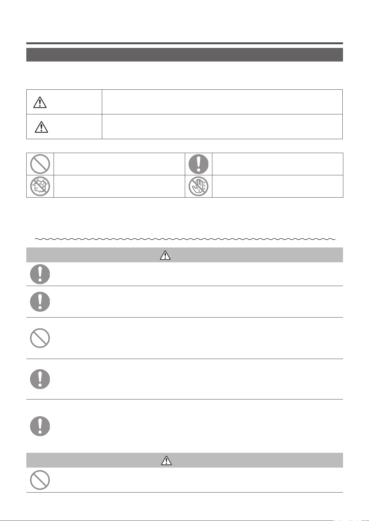
●The following pictograms are used in the text.
Never do. Always follow the instructions given.
Absolutely keep water away. Absolutely keep wet hands away.
● Keep this manual at a safe place where you can consult with whenever necessary. Show this
manual to installers when moving or repairing the unit. When the ownership of the unit is
transferred, this manual should be given to a new owner.
●Electrical wiring work must be implemented only by qualified specialists.
such as death, severe injury, etc.
Failure to follow these instructions may cause injury, property damage or, serious
consequences depending on.
WARNING
Consult your dealer or a professional contractor to install the unit.
Improper installation made on your own may cause electric shocks, fire or dropping of the unit.
Consult your dealer when moving, disassembling or repairing the unit.
Never modify the unit.
Improper handling may result in injury, electric shocks, fire, etc.
Avoid using combustible substances (hair spray, insecticide, etc)
near the unit.
Do not use benzene or paint thinner to clean the unit.
It could cause cracks, electric shocks or fire.
Stop operation under abnormal situation.
If continued, it could result in break-down, electric shocks, fire, etc.
If any abnormal condition (burnt odor etc.) occurs, stop operation, turn off the power
switch and consult your dealer.
This appliance can be used by children aged from 8 years and above
and persons with reduced physical, sensory or mental capabilities or
lack of experience and knowledge if they have been given supervision
or instruction concerning use of the appliance in a safe way and
understand the hazards involved.
CAUTION
Do not use or let use the unit or remote control as play equipment.
Improper operations could cause ill health or health disorder.
- 2 -
Page 5
Never disassemble the remote control.
If you touch internal parts accidentally, you could get electric shocks or cause trouble.
Consult your dealer when it is necessary to inspect its interior.
Do not wash the remote control with water or liquid.
It could cause electric shocks, fire or break-down.
Do not touch electric parts or operate buttons or screens with wet hands.
It could cause electric shocks, fire or break-down.
Do not dispose the remote control by yourself.
It could destruct the environment. Ask your dealer when it is necessary to dispose the
remote control.
Note
The remote control should not be installed where it is exposed to
direct sunlight or the ambient temperatures become higher than 40°C
or lower than 0°C.
It could cause deformation, discoloration or break-down.
Do not use benzene, paint thinner, wipes etc. to clean the remote control.
It could discolor or break-down the remote control. Wipe it with a piece of cloth which is
squeezed tightly after wetting with diluted neutral detergent. Finish up the cleaning by
wiping with a piece of dry cloth.
Do not pull or twist the cable of the remote control.
It could cause break-down.
Do not tap the remote control buttons or screen with pointed objects.
It could damage or cause break-down.
Precautions for waste disposal
Your Air Conditioning product may be marked with this symbol. It means that waste electrical and
electronic equipment (WEEE as in directive 2012/19/EU) should not be mixed with general
household waste. Air conditioners should be treated at an authorized treatment facility for re-use,
recycling and recovery and not be disposed of in the municipal waste stream. Please contact the installer
or local authority for more information.
Unit specifications
Item Description
Product dimensions 120 (W) x 120 (H) x 19 (D) mm (not including protruded section)
Weight 0.20 kg
Power supply DC 18 V
Power consumption 0.6 W
Usage environment Temperature: 0 to 40 °C
Material Casing: ABS
- 3 -
Page 6
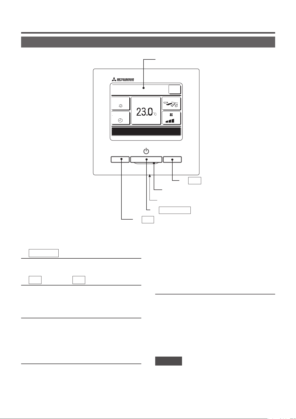
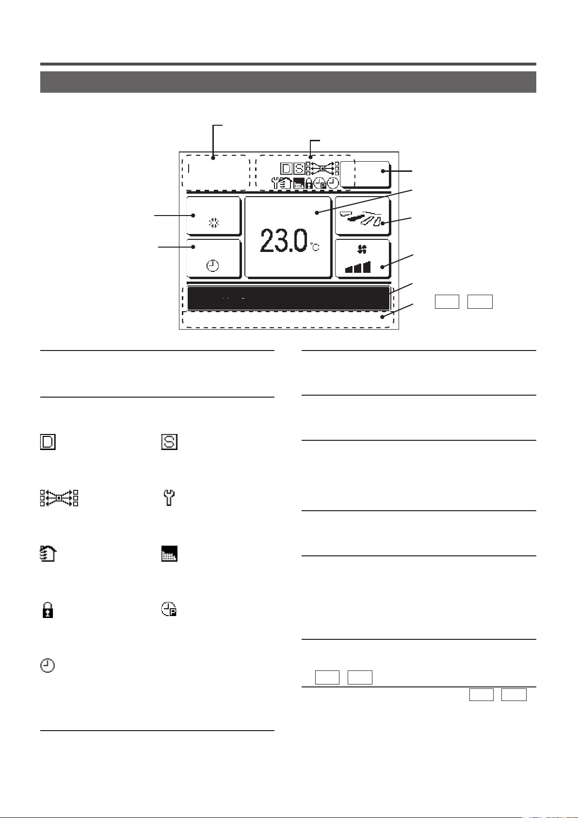
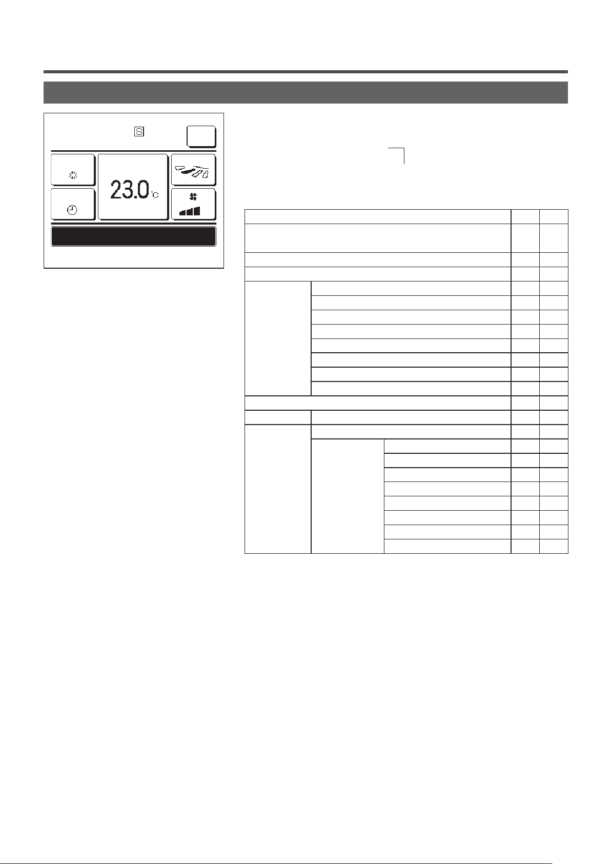
Names and functions of sections on the R/C
⑤ LCD (With backlight)
16:14
(Mon)
Cooling
Timer
Now stopping.
Set temp
F2: Energy-savingF1: High power
Menu
Direction
③ F2 switch
(Operating section)
④ Operation lamp
⑥ USB port (mini-B)
switch
② F1
① Run/Stop
switch
Touch panel system, which is operated by tapping the LCD screen with a finger, is employed for any operations other
than the ① Run/Stop, ② F1 ③ F2 switches.
Run/Stop
①
switch
One push on the button starts operation and another
push stops operation. (☞page 8)
②
F1
switch ③
F2
switch
This switch starts operation that is set in F1/F2
function setting (☞page 63).
(☞page 13)
④ Operation lamp
This lamp lights in green (yellow-green) during
operation. It changes to red (orange) if any error
changed. (☞page 36)
If the backlight is ON setting, when the screen is
tapped while the backlight is turned off, the backlight
only is turned on. (Operations with switches ①, ②
and ③ are excluded.)
⑥ USB port
USB connector (mini-B) allows connecting to a
personal computer.
For operating methods, refer to the instruction
manual attached to the software for personal
computer (remote control utility software).
occurs.
Operation lamp luminance can be changed.
(☞page 37)
⑤ LCD (With backlight)
A tap on the LCD lights the backlight.
The backlight turns off automatically if there is no
operation for certain period of time.
Lighting period of the backlight lighting can be
- 4 -
Note
・ When connecting to a personal computer, do not connect
simultaneously with other USB devices.
Please be sure to connect to the computer directly, without going
through a hub, etc.
Page 7
Names and functions of sections on the R/C (Display)
*All icons are shown for the sake of explanation.
① Clock, Room name display
② Icon display
TOP screen
④ Change operation
mode button
⑧ Timer button
MEETING1
14:00 (Mon)
Auto
Timer
In operation for running.
F1: High power F2: Energy-saving
Set temp
Menu
Direction
③ Menu button
⑤ Change set temp
button
⑥ Change flap
direction button
⑦ Change the fan
speed button
⑨ Message display
⑩ F1 , F2 switch
function display
① Clock, Room name display
Displays the current time (☞page33) and the room
name (☞page 58).
② Icon display
Each icon is displayed when one of following settings is
going on.
When the demand
control is effective.
When the
central control (Optional) is
running.
During the ventilation
operation.
(☞page 32)
When the Permission/
Prohibition setting is made.
(☞page 52)
When the weekly
timer is set.
(☞page 42)
③ Menu button
When setting or changing other than the following ④-⑧,
tap the menu button. Then menu items are displayed, select
one and set.
When setting is made
from the sub R/C.
(☞page 18)
When the periodical
inspection is necessary.
(☞page 69)
When ”lter sign” is up.
(☞
page
65)
When the peak-cut
timer is set.
(☞page 22)
④
Change operation mode button
Displays the operation mode which is selected currently.
Tap this button to change the operation mode.
⑤ Change set temp button (☞page 9)
Displays the temperature which is set currently. Tap this
button to change the set temperature.
⑥ Change flap direction button (☞page 10)
Displays the flap direction which is selected currently.
When the 3D auto flow operation is enabled, 3D auto
display will appear. Tap this button to change the flap
direction.
⑦ Change the fan speed button (☞page 13)
Displays the fan speed which is selected currently. Tap this
button to change the fan speed.
⑧ Timer button (☞page 37)
Displays simplified contents of the timer which is set
currently.
(When two or more timers are set, contents of the timer
which will be operated immediately after is displayed.)
Tap this button to set the timer.
⑨ Message display
Status of air conditioner operation and messages of the
R/C operations etc. are displayed.
F1
⑩
Displays the function that is set for each
switch.
The function for these switches can be changed in F1/F2
function setting
,
F2
switch function Display
(☞page 63)
(☞page 9)
,
F1
F2
- 5 -
Page 8
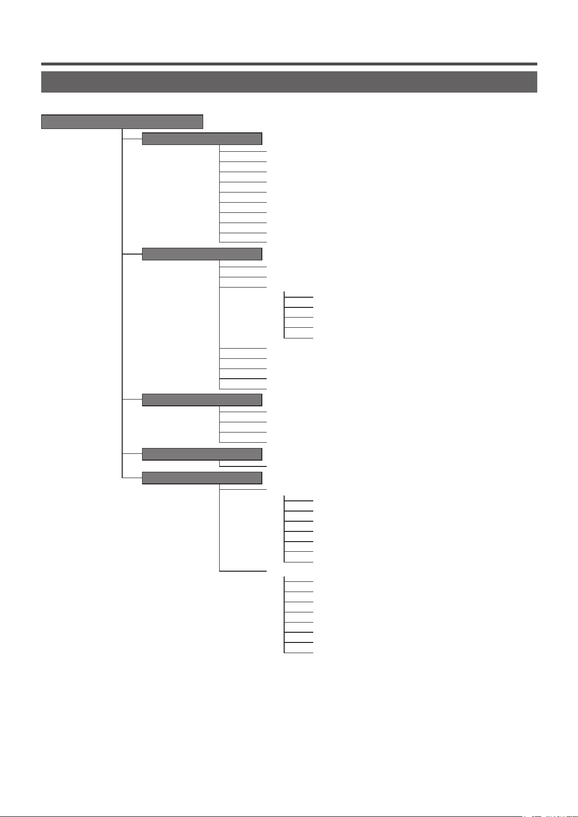
Menu item
Main menu
Run ………………………………………………………………………………………… 8
Stop ………………………………………………………………………………………… 8
Change operation mode ………………………………………………………………… 9
Change set temp ………………………………………………………………………… 9
Change ap direction …………………………………………………………………… 10
Change the fan speed …………………………………………………………………… 13
F1, F2 switch operation …………………………………………………………………… 13
High power operation …………………………………………………………………… 14
Energy-saving operation ………………………………………………………………… 15
Silent mode control ……………………………………………………………………… 64
Individual ap control ……………………………………………………………………… 27
Anti draft setting …………………………………………………………………………… 31
Timer ……………………………………………………………………………………… 37
Set ON timer by hour …………………………………………………… 39
Set OFF timer by hour ………………………………………………… 40
Set ON timer by clock …………………………………………………… 41
Set OFF timer by clock ………………………………………………… 41
Conrm …………………………………………………………………… 42
Favorite setting …………………………………………………………………………… 49
Weekly timer ……………………………………………………………………………… 42
Home leave mode ………………………………………………………………………… 46
External ventilation ……………………………………………………………………… 32
Select the language ……………………………………………………………………… 65
Sleep timer ………………………………………………………………………………… 21
Peak-cut timer …………………………………………………………………………… 22
Automatic temp set back ………………………………………………………………… 25
Infrared sensor (motion sensor) control ………………………………………………… 26
Filter sign reset …………………………………………………………………………… 65
Initial settings ……………………………………………………………………………… 33
Clock setting …………………………………………………………… 33
Date & time display ……………………………………………………… 34
Summer time …………………………………………………………… 35
Contrast ………………………………………………………………… 35
Backlight ………………………………………………………………… 36
Controller sound ………………………………………………………… 36
Operation lamp luminance ……………………………………………… 37
Administrator settings …………………………………………………………………… 51
Permission/Prohibition setting ………………………………………… 52
Outdoor unit silent mode timer ………………………………………… 53
Setting temp range ……………………………………………………… 54
Temp increment setting ………………………………………………… 56
Set temp display ………………………………………………………… 56
R/C display setting ……………………………………………………… 57
Change administrator password ……………………………………… 62
F1/F2 function setting …………………………………………………… 63
Basic operation
Useful functions
Energy-saving setting
Filter
User setting
- 6 -
Page 9
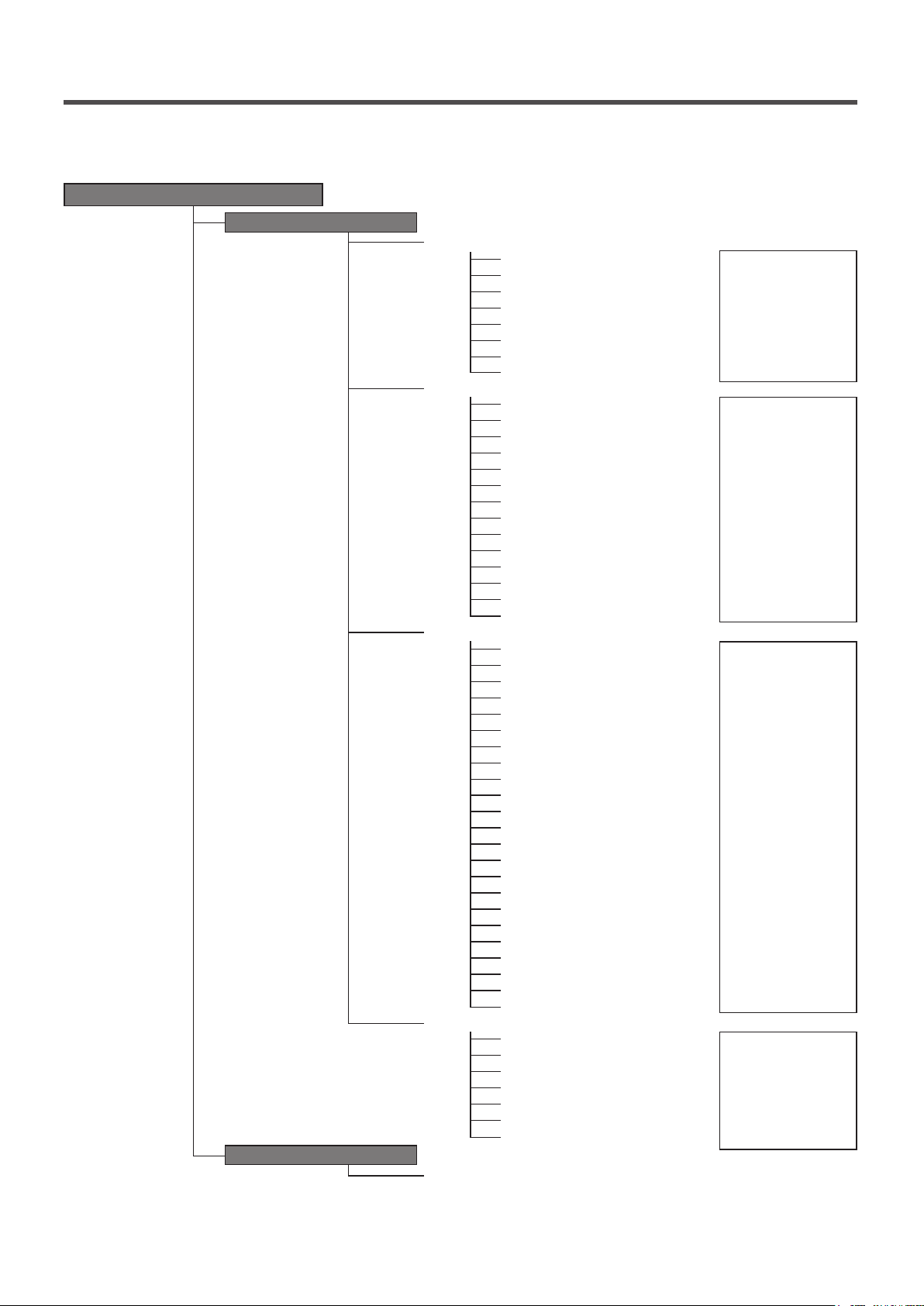
Main menu
Installation settings
Installation date ………………………………………………………… 25
Company information …………………………………………………… 25
Test r un …………………………………………………………………… 25
Static pressure adjustment ……………………………………………… 25
Change auto-address …………………………………………………… 25
Address setting of main IU ……………………………………………… 25
IU back-up function ……………………………………………………… 25
R/C function settings
Main/Sub of R/C ………………………………………………………… 25
Return air temp ………………………………………………………… 25
R/C sensor ……………………………………………………………… 25
R/C sensor adjustment ………………………………………………… 25
Operation mode ………………………………………………………… 25
ºC / ºF …………………………………………………………………… 25
Fan speed ……………………………………………………………… 25
External input …………………………………………………………… 25
Upper/lower ap control ………………………………………………… 25
Left/right ap control …………………………………………………… 25
Ventilation setting ……………………………………………………… 25
Auto-restart ……………………………………………………………… 25
Auto temp setting ……………………………………………………… 25
Auto fan speed ………………………………………………………… 25
IU settings
Fan speed setting ……………………………………………………… 25
Filter sign ………………………………………………………………… 25
External input 1 ………………………………………………………… 25
External input 1 signal …………………………………………………… 25
External input 2 ………………………………………………………… 25
External input 2 signal …………………………………………………… 25
Heating thermo-OFF temp adjustment ……………………………………………… 25
Return temperature adjustment ………………………………………… 25
Anti-frost temp …………………………………………………………… 25
Anti-frost control ………………………………………………………… 25
Drain pump operation …………………………………………………… 25
Keep fan operating after cooling is stopped ……………………………………………………25
Fan circulator operation ………………………………………………… 25
Control pressure adjust ………………………………………………… 25
Auto operation mode …………………………………………………… 25
Thermo. rule setting …………………………………………………… 25
Auto fan speed control ………………………………………………… 25
IU overload alarm ……………………………………………………… 25
External output setting ………………………………………………… 25
Service & Maintenance
IU address ……………………………………………………………… 25
Next service date………………………………………………………… 25
Operation data …………………………………………………………… 25
Error display ……………………………………………………………… 25
Saving IU settings ……………………………………………………… 25
Special settings ………………………………………………………… 25
Indoor unit capacity display …………………………………………… 25
Contact company ………………………………………………………………………… 68
Service setting
Contact company
Infrared sensor (motion sensor) setting
Fan control in cooling thermo-OFF
Fan control in heating thermo-OFF
Keep fan operating after heating is stopped
Intermittent fan operation in heating
Please refer to the
installation manual.
…………………………………… 25
Please refer to the
installation manual.
……………………………………… 25
……………………………………… 25
Please refer to the
installation manual.
……………………………………… 25
……………………………………… 25
Please refer to the
installation manual.
- 7 -
Page 10
2. Menu items
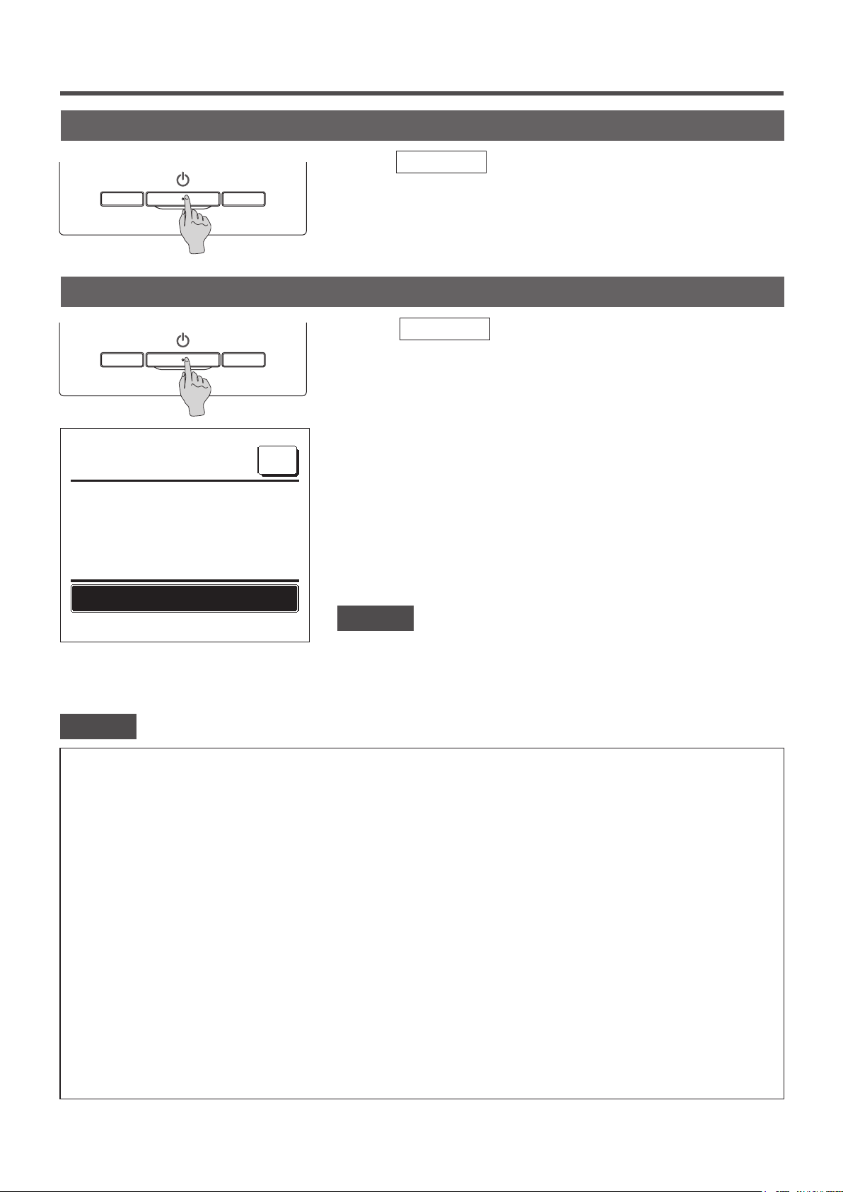
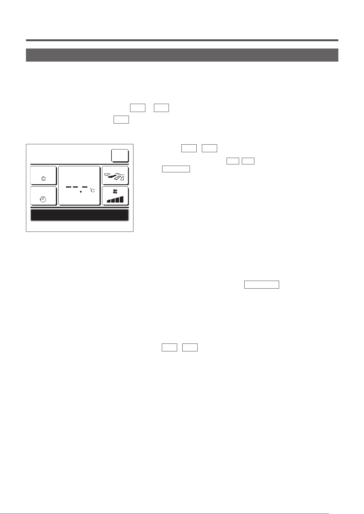
Run
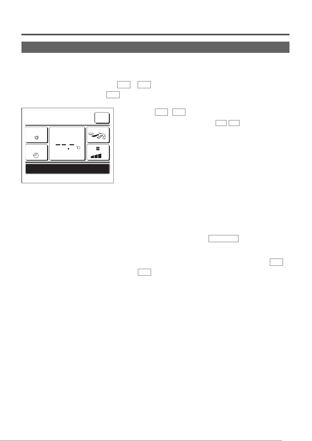
Stop
16:23
(Mon)
Menu
Push the
Run/Stop
switch.
Operation lamp (green) lights and operation starts.
Press the
Run/Stop
switch while the unit is in operation.
The operation lamp turns off and the operation stops.
When the operation stops, all operation buttons on the screen turn off.
When the set lighting time of backlight (☞page36) is counted up, the
backlight turns off.
When the screen is tapped, the backlight lights, and all operation buttons
are displayed.
Now stopping.
F1: High power
F2: Energy-saving
Note
・ Do not shut down the power supply immediately after the stop of operation.
It should be waited for more than 5 minutes till the residual operation time of drain motor
is counted up. Otherwise, it could cause water leakage or breakdown.
Advice
・ A message “Invalid request” may be displayed when a button is pushed. This is not a fault but it is because the button operation is set to
the “Disable”. (☞page 52)
・ The unit starts to operate initially with the following settings after the power on. These settings can be changed as desired.
Central control …… OFF
Operation mode …… With auto mode: Auto cooling
…… Without auto mode: Cooling
Set temp …… 23.0°C
Fan speed …… 3-speed
Flap direction …… When cooling: position 2, when heating: position 3 (☞page 10)
*When an FDK with a left/right flap is connected, left/right flap direction: center, 3D AUTO: disabled
・ In the following cases, a message “Operation mode is invalid.” is displayed and it changes to the fan operation, because operation
modes are not matched.
① When Heating (including auto heating) is selected for Operation mode while using an OU for cooling only.
② When Heating is selected for Operation mode while controlling multiple units including units allowed for both cooling and heating and units
for cooling only.
③ When different operation modes are selected between IUs which are connected to a OU that do not allow mixed operation of cooling
and heating.
- 8 -
Page 11
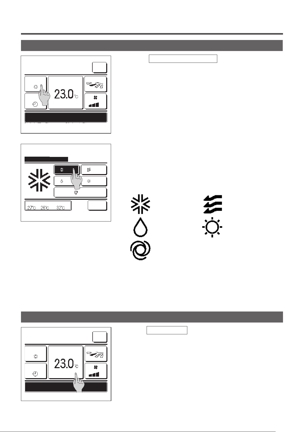
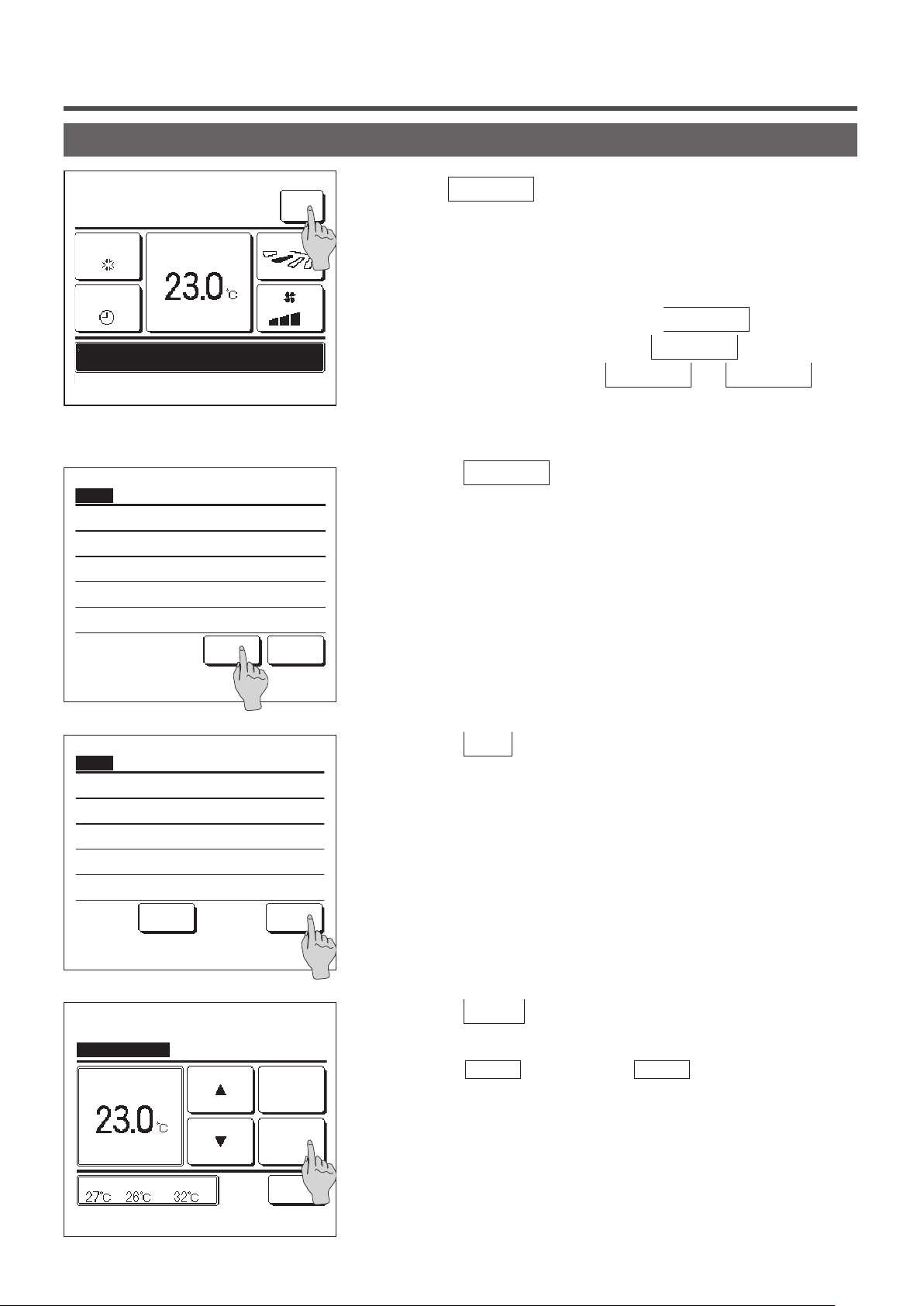
Change operation mode
16:14
(Mon)
Menu
Tap the Change operation mode button on the TOP screen.
1
Cooling
Timer
Now stopping.
F1: High power
Change operation mode
Please select operation mode.
Set temp
Cooling
OutdoorRoomR/C
F2: Energy-saving
Dry
Auto
Direction
Fan
Heating
Back
When the Change operation mode screen is displayed, tap the
2
button of desired mode.
The operation mode changes, and the display returns to the TOP
screen.
Icons displayed have the following meanings.
Cooling Fan
Change set temp
16:14
(Mon)
Cooling
Timer
Set temp
Menu
Direction
Dry Heating
Auto
■Operation modes which cannot be selected depending on combinations of IU and
OU are not displayed.
■When the Auto is selected, the cooling and heating switching operation is performed
automatically according to indoor and outdoor temperatures.
1
Tap the
Change set temp
button on the TOP screen.
Now stopping.
F1: High power
F2: Energy-saving
- 9 -
Page 12
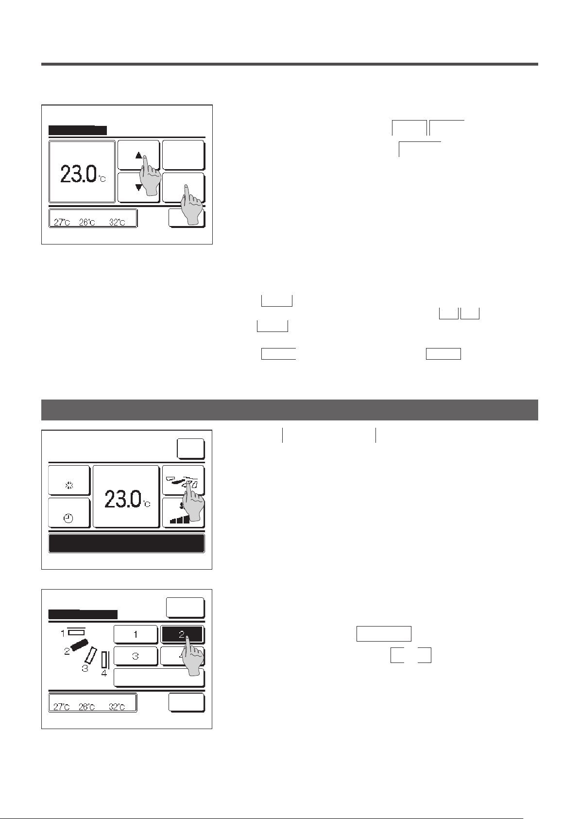
Change set temp
When the Change set temp screen is displayed, select the
2
temperature as desired with using
▲
▼
buttons.
Auto
Set
to set temp & tap [Set].
Tap
▲▼
OutdoorRoomR/C
Back
Change flap direction
After selecting the set temp, tap the
3
button. The display
Set
returns to the TOP screen.
■For allowable temperature setting ranges, refer to the range setting of set temp (☞
page 54).
■Reference set temp
Cooling … 26 to 28°C
Dry … 24 to 26°C
Heating … 20 to 24°C
Fan … Setting temp is not requi
■If the
■If the
Auto is selected for the set temp, the set temp display shows “0”.
Temperature can be adjusted higher or lower with using
that
Auto is not displayed and cannot be set when SC-SL2, SC-SL3, or SC-SL4
is connected.
Back button is tapped without tapping the Set button, the selected
set temp is invalidated and the display returns to the TOP screen.
red.
▲ ▼ buttons. Note
16:14
(Mon)
Cooling
Timer
Now stopping.
F1: High power
Change flap direction
Select the flap direction.
Set temp
OutdoorRoomR/C
F2: Energy-saving
Auto swing
Menu
Direction
Ind. flap
Control
Back
Tap the
1
Change flap direction
button on the TOP screen.
When an FDK with a left/right ap is not connected: ☞2
When one or more FDKs with a left/right ap are connected: ☞3
When the Change ap direction screen is displayed, tap the button
2
of desired ap direction.
To swing the ap, tap the
Auto swing
To x the ap position, tap one of
button.
to 4 buttons.
1
After selecting the ap direction,
When an FDK with a left/ right ap is not connected, the display
returns to the TOP screen. (☞1)
When an FDK with a left/right ap is connected, the display returns
to the Select ap screen. (☞3)
- 10 -
Page 13
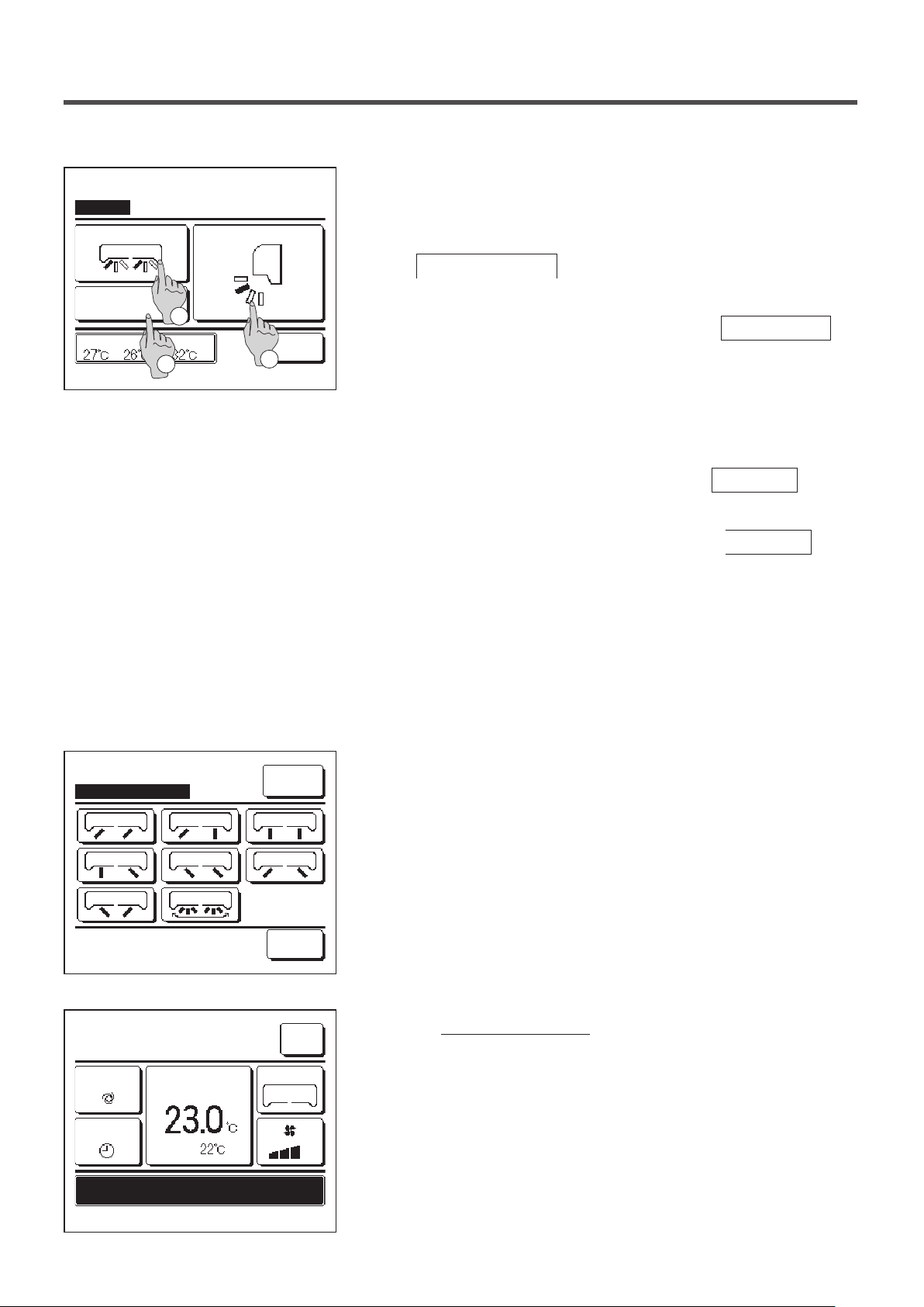
Select flap
Left/right flap
Upper/lower flap
When one or more FDKs with a left/right ap are connected, the
3
Select ap screen is displayed. Select the desired ap direction.
To change the up/down ap direction, tap the
①
Upper/lower flap
button. The Change ap direction screen
3D AUTO
R/C Room
Select the flap to change.
2
Outdoor
3
for the up/down ap is displayed. (☞2)
To change the left/right ap direction, tap the
②
Back
1
button. The Change ap direction screen for the left/right ap is
Left/right flap
displayed. (☞4)
The 3D auto ow operation automatically controls the fan speed
③
and ap direction to efciently condition the air of the entire room.
To switch to the 3D auto ow operation, tap
3D AUTO
to
enable the operation.
To disable the 3D auto ow operation, tap the
3D AUTO
again.
The ap direction returns to the direction that was set before the
3D auto ow operation was enabled. The 3D auto ow operation
will also be disabled when you change the up/down or left/right
ap direction during the 3D auto ow operation.
Change flap direction
MEETING1
16:14
(Mon)
Auto
Timer
Now stopping.
Set temp
Room
Ind. flap
Control
Back
Menu
Direction
3D AUTO
Tap the desired ap direction. After selecting the ap direction, the
4
display returns to the Select ap screen. (☞1)
When the 3D auto ow operation is enabled, “3D AUTO” is displayed
5
on the
Change flap direction
button, as shown on the left.
F1: High power
F2: Energy-saving
- 11 -
Page 14

■When multiple IUs are connected to the remote control for a mixed environment consisting of FDKs with a left/right flap and IUs without a
left/right flap, enabling the 3D auto flow operation will set the models without a left/right flap to a flap position set before the 3D auto flow
operation was started.
■Since the flap is controlled automatically in the following operation, it may differ from the display on the R/C.
∙ When the room temperature is higher than the set temp (In case of the heating operation)
∙ When the “In operation for heating standby. ” or “In operation for defrosting.” is displayed (In case of the heating operation).
Cool air is blown horizontally not to blow directly to human body.
∙ In a high humidity environment (during cooling operation)
■When you select Auto swing while the Anti draft setting (☞page 31) is enabled, the flap will not swing and be set at flap position
■Changing the left/right flap direction and 3D auto flow operation cannot be performed from the SC-SL2, SC-SL3, or SC-SL4. Also note that
3D auto flow operation will not be disabled when you change the flap direction from the SC-SL2, SC-SL3, or SC-SL4 during a 3D auto
flow operation.
Note
・ Do not manually move the flaps or panel with anti draft by force. It could damage these flaps and panels.
・ Do not blow air downward for a long period of time during the cooling operation. Condensation may be generated and water may drip from
the side panel. (In case of Ceiling suspended type)
・ For FDKs with a left/right flap, it is recommended that the flap should be set toward the right side when there is a wall on the left, or set
toward the left side when there is a wall on the right. For more information, refer to the Notes in the Individual flap control section (☞page
30).
1 .
- 12 -
Page 15
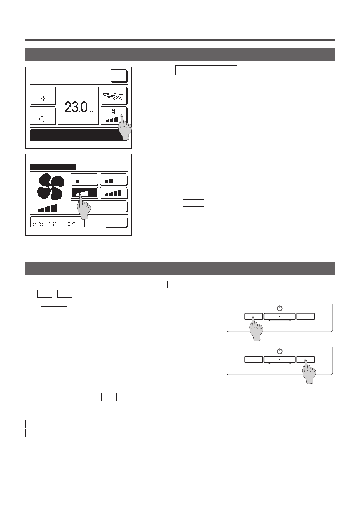
Change the fan speed
16:14
(Mon)
Cooling
Timer
Now stopping.
F1: High power F2: Energy-saving
Change the fan speed
Select the fan speed.
Set temp
OutdoorRoomR/C
Direction
Auto
Menu
Back
Tap the
1
When the Change the fan speed screen is displayed, tap the button
2
Change the fan speed
button on the TOP screen.
of desired fan speed.
After setting the fan speed, the display returns to the TOP screen.
■Fan speeds which can be set vary depending on the models of IU.
■When the
depending on the capacity.
Note that
SL3 is connected.
Auto is selected, the fan speed is changed automatically
Auto is not displayed and cannot be set when SC-SL2 or SC-
F1/F2 switch operation
You can set any of the following functions to the F1 and F2 switches.
The F1
usual Menu
・High power operation …☞page 14
・Energy-saving operation …☞page 15
・Silent mode control …☞page 64
・Home leave mode …☞page 46
・Favorite setting operation …☞page 50
・Filter sign reset …☞page 65
Changing the function of the F1 or F2 switch can be performed with the F1/F2 function setting (☞page 63).
The following functions are set as factory settings.
You may change these settings as desired.
F1
F2
/ F2 switches act as shortcuts; it can be much easier and faster than starting an operation from the
on the TOP screen.
switch …High power operation
switch …Energy-saving operation
- 13 -
Page 16
High power operation
The high power operation adjusts the room temperature quickly to a pleasant level by increasing the operation
capacity.
The high power operation continues for 15 minutes at the maximum and returns to the normal operation automatically.
When the operation mode is changed, the high power operation returns to the normal operation, too.
High power operation must be set to the F1
or F2 switch (☞page 63).
High power operation is set to the F1
15:50
(Mon)
Cooling
Timer
In operation for high power.
F1: High power
Set temp
F2: Energy-saving
Menu
Direction
switch as the factory setting.
Push the
1
■Operation will start when the
Run/Stop
■High power operation is only allowed when Heating or Cooling is selected for
the operation mode.
(
F1
switch is off.
Message “In operation for high power.” is displayed on the R/C
screen, and “—, —°C” is displayed on the Set temp button during
the high power operation.
■Set temp and change fan speed operations are disabled during high power
operation.
High power operation is terminated when you perform one of the
2
following.
When you terminate through a
・
) switch to start the high power operation.
F2
F1 (F2
) switch is pushed, even if
Run/Stop
operation
When you change the operation mode
・
When15 minutes have elapsed since the high power operation
・
started
When you terminate the high power operation with the
・
F1
(
F2
) switch
- 14 -
Page 17
Energy-saving operation
Use this operation to save energy. Set temp is fixed at 28°C in the cooling operation or 22°C in the heating operation.
Since the capacity is controlled automatically based on the outdoor temperature, energy can be saved without losing
comfort.
Energy-saving operation must be set to the F1
or F2 switch (☞page 63)
Energy-saving operation is set to the F2
16:04
(Mon)
Auto
Timer
In operation for energy-saving.
F1: High power F2: Energy-saving
Set temp
Menu
Direction
switch as the factory setting.
Push the
1
■Operation will start even if you press the
stopped.
■Energy-saving operation is only allowed when Heating, Cooling or Auto is
selected for the operation mode.
F1
(
)switch to start the energy-saving operation.
F2
F1 (F2
) switch while the unit is
Message “In operation for energy-saving.” is displayed on the screen
during the energy-saving operation. Set temp is xed at “28.0°C” in
the cooling operation or “22.0°C” in the heating operation. Set temp
shows “- -°C” in the automatic operation mode.
■Set temp cannot be changed during the energy-saving operation. If it is
attempted, a message “Invalid request” is displayed on the screen.
Energy-saving operation is terminated when you perform the
2
following.
When you terminate through a
・
Run/Stop
operation
When you change the operation mode
・
When you terminate the energy-saving operation with the
・
) switch
F2
F1
(
- 15 -
Page 18
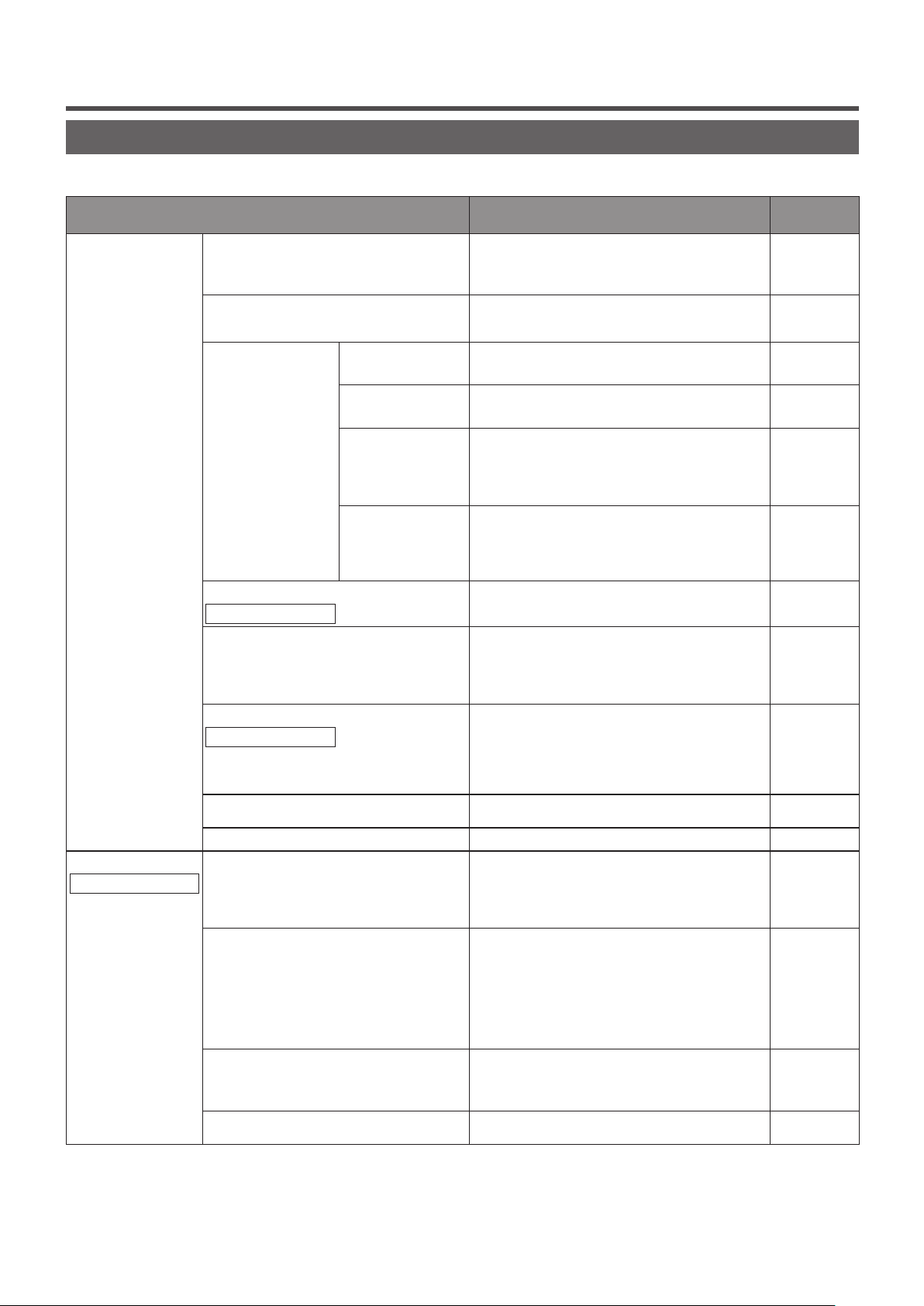
3. Quick reference of menu items
Quick reference of menu items
It is necessary to input the Administrator password for menu items showing.
Setting and display items Details
Useful functions Individual flap control
Anti draft setting
Timer Set ON timer by
Favorite setting
Administrator password
Weekly timer
Home leave mode
Administrator password
External ventilation
Select the language
Energy-saving setting
Administrator password
Sleep timer
Peak-cut timer
Automatic temp set back
Infrated sensor (motion sensor) control
hour
Set OFF timer by
hour
Set ON timer by
clock
Set OFF timer by
clock
Set the moving range (upper and lower limit positions) of the
flap at each blow outlet of IU.
Set also the left limit position-rights limit position if FDK is
used.
If the panel with anti draft is used, set enable/disable of the
each operation mode and anti draft operation of each blow
outlet.
Set the time to operate the unit after stopping the operation
within the range of 1 - 12 hours (at 1-hour intervals).
Set the time to stop the operating unit within the range of 1
- 12 hours (at 1-hour intervals).
Set the clock time to start operation.
■The time can be set at 5-minute intervals.
■It can be selected from once (only one day) or every time
(every day).
*Clock setting is necessary to set the timer.
Set the time to stop operation.
■The time can be set at 5-minute intervals.
■It can be selected from once (only one day) or every time
(every day).
*Clock setting is necessary to set the timer.
Set each operation mode and setting temperature, fan speed,
flap direction for Favorite setting 1 or Favorite setting 2.
On timer or Off timer on weekly basis can be set.
■8-operation patterns per day can be set at the maximum.
■The time can be set at 5-minute intervals.
Holiday setting (including temporary day off) is available.
■
*Clock setting is necessary to set the time.
When the unit is not used for a long period of time, the room
temperature is maintained at a moderate level, avoiding
extremely hot or cool temperatures.
■Cooling or heating is operated according to the outdoor
temperature and the set temp.
■Set temp and fan speed can be set.
The ventilation is turned on or off if ventilation equipment is
attached.
Set the language to be displayed on the R/C.
Set the time period from start to stop of operation.
■The selectable range of setting time is from 30 to 240
minutes (at 10-minute intervals).
■When the setting is “Enable”, this timer will activate
whenever any operation starts.
Set the times to start and stop the capacity limiting operation
and the peak-cut %.
■4 operation patterns per day can be set at the maximum.
■The setting time can be changed at 5-minute intervals.
■The selectable range of peak-cut % is from 0.40 to 80% (at
20% intervals).
Holiday setting (including temporary day off) is available.
■
*Clock setting is necessary.
It returns to the set temperature when the set time is counted
up.
■The selection range of the set time is from 20 to 120
minutes (at 10-minute intervals).
If the motion detector is used, set enable/disable of Power
Control and autosave.
page 27
page 31
page 39
page 40
page 41
page 41
page 50
page 42
page 46
page 32
page 65
page 21
page 22
page 25
page 26
- 16 -
Page 19
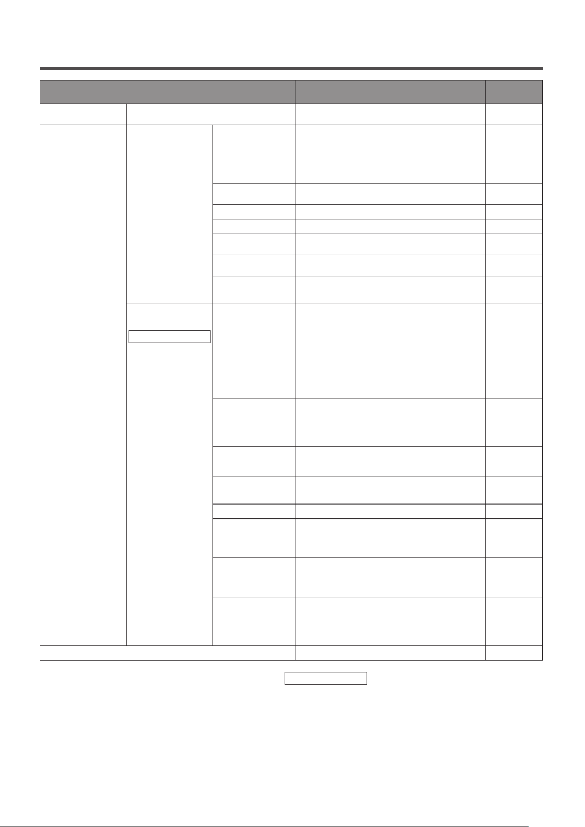
Setting and display items Details
Filter Filter sign reset
User setting Initial settings Clock setting
Date & time display
Summer time
Contrast
Backlight
Controller sound
Operation lamp
luminance
Administrator
settings
Administrator password
Contact company & Error display
Permission/
Prohibition setting
Outdoor unit silent
mode timer
Setting temp range
Temp increment
setting
Set temp display
R/C display setting
Change
administrator
password
F1/F2 function
setting
Reset the filter sign.
Set next cleaning date.
Set and correct the current date and time.
■When the power supply is interrupted for 80 hours or less,
the clock continues to operate with the built-in backup
batteries.
If it is interrupted for more than 80 hours, it is necessary to
renew the setting.
Set whether the date and time are displayed or not, and
select 12H or 24H and AM or PM position.
Current time is advanced or delayed by 1 hour.
Contrast of LCD can be adjusted.
Select whether the backlight is used or not, and set the
lighting time.
Select whether the controller sound is actuated at the touch
panel operation or not.
Adjust operation lamp luminance.
■ Set the permission/prohibition for each of following
operations:
[Run/Stop] [Change set temp] [Operation mode]
[Change flap direction]
[Change the fan speed] [High power operation] [Energysaving operation] [Timer]
■Set the administrator password request during operation.
[Individual flap control]
[Weekly timer] [Select the language]
[Filter sign reset]
The period of time to operate the unit by prioritizing the
quietness can be set.
■ Starting and stopping times can be set for the silent mode
operation.
■ The time can be set at 5-minute intervals.
Restrict the setting range of temperature.
■Temperature range can be restricted depending on operation
modes.
Set the interval for setting temperature (0.5°C/1.0°C).
Set temperature display method can be selected.
Register the names of remote control and indoor unit.
Set Yes or No for the need of indoor temperature display.
Set Yes or No for the need for the display of error code, heating
standby, defrosting operation on and automatic cooling/heating.
Change the administrator password.
Set the functions of F1 and F2 switch.
Available functions:
[High power operation] [Energy-saving operation] [Silent
mode cont.] [Home leave mode] [Favorite set 1] [Favorite
set 2] [Filter sign reset]
Address of the service contact is displayed.
page 65
page 33
page 34
page 35
page 35
page 36
page 36
page 37
page 52
page 53
page 54
page 56
page 56
page 57
page 62
page 63
page 68
It is necessary to input the administrator password for menu items indicated with
- 17 -
Administrator password
Page 20
Restrictions on the sub R/C
15:54
(Mon)
Cooling
Set temp
Menu
Direction
When one IU is controlled with 2 R/Cs, the following settings cannot be
made on the sub R/C. It is necessary to use the main R/C.
In case of the sub R/C, the icon
S is displayed on the R/C screen.
Timer
Now stopping.
F1: High power F2: Energy-saving
○: operable ×: not operable
R/C operations Main Sub
Run/Stop, Change set temp, Change flap direction, Auto swing,
Change fan speed operations
High power operation, Energy-saving operation ○ ○
Silent mode control ○ ×
Useful functions Individual flap control ○ ×
Anti draft setting ○ ×
Timer ○ ○
Favorite setting ○ ○
Weekly timer ○ ×
Home leave mode ○ ×
External ventilation ○ ○
Select the language ○ ○
Energy-saving setting ○ ×
Filter Filter sign reset ○ ○
User setting Initial settings ○ ○
Administrator
settings
Permission/Prohibition setting ○ ×
Outdoor unit silent mode timer ○ ×
Setting temp range ○ ×
Temp increment setting ○ ×
Set temp display ○ ○
R/C display setting ○ ○
Change administrator password ○ ○
F1/F2 function setting ○ ○
○ ○
- 18 -
Page 21
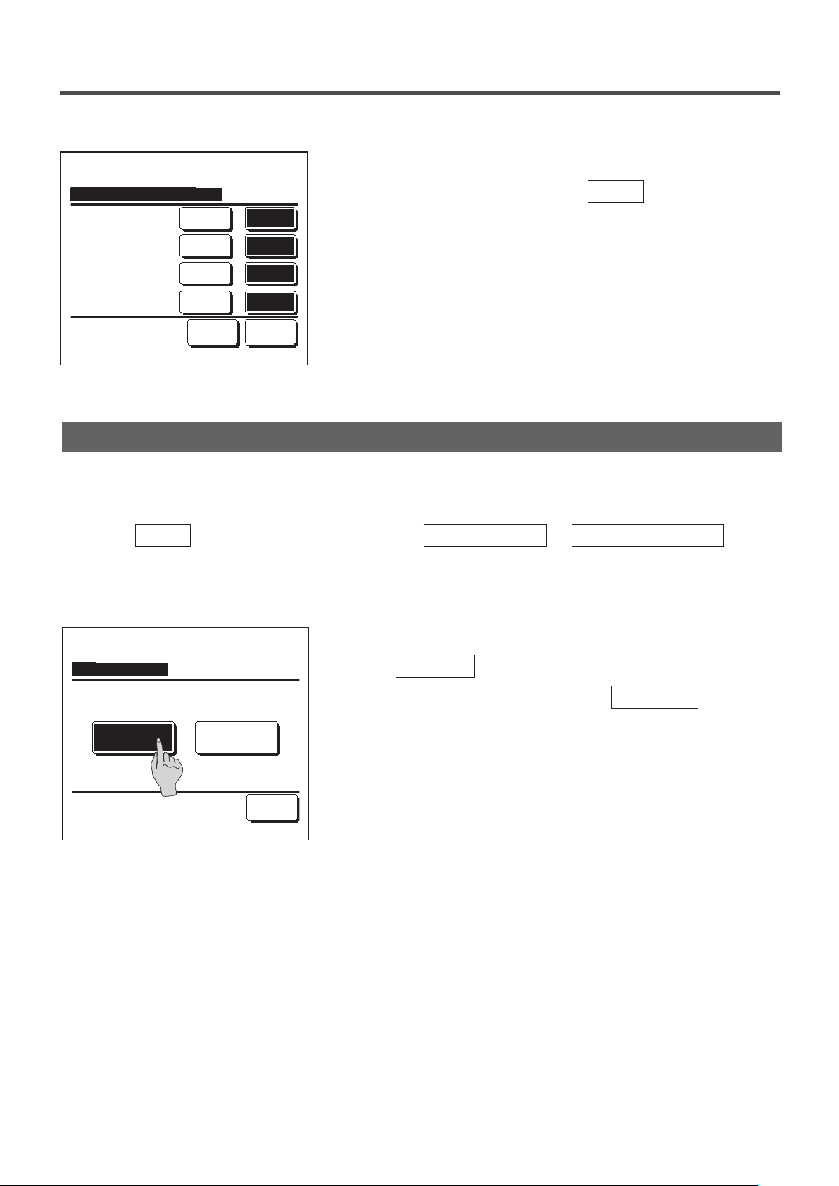
Operations on menu screens
16:14
(Mon)
Cooling
Timer
Now stopping.
F1: High power F2: Energy-saving
Menu
Useful functions
Energy-saving setting
Filter
User setting
Service setting
Set temp
Direction
Menu
1
Tap the
Menu
button on the TOP screen.
Main menu screen is displayed.
When a desired menu item is tapped, setting screen for each item is
displayed.
When there are two or more pages, the
displayed at the leading page and the
displayed at the last page. The
Next
Next
Previous
and
button is
button is
Previous
buttons are displayed on pages in between.
When the
2
Next
button is tapped, next main menu screen is
displayed.
Select the item.
Menu
Contact company
Select the item.
Change set temp
Next Back
Previous Back
Auto
When the
3
button is tapped, the display returns to the TOP
Back
screen.
When the
4
button is displayed on the setting screen for
Set
each item, tapping this button conrms the setting.
■If you tap Back without tapping the Set button, the settings made will
not be applied, and the display returns to the original screen.
Tap
to set temp & tap [Set].
▲▼
Set
OutdoorRoomR/C
Back
- 19 -
Page 22
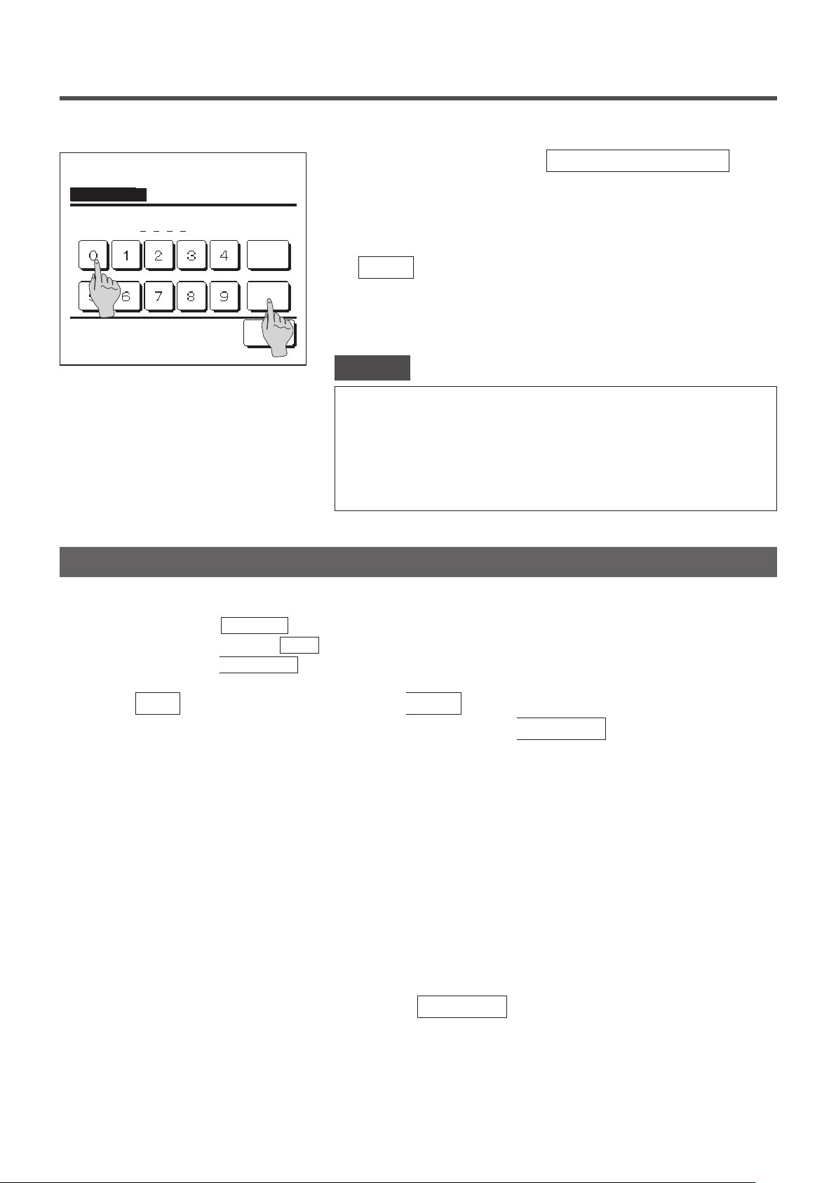
Input password
Input the administrator password.
When an item is referenced to
5
Administrator password in this
manual, the Input password screen is displayed after selecting the
menu.
Enter the administrator password (4-digit number) and tap the
Input 4 digit number & tap [Set]
Delete
Set
Back
When the password is unknown or wrong, the setting cannot be
changed.
Set
button.
Advice
· The administrator password is provided so that these operations and settings are
restricted to administrators/managers only (such as the owner of the building).
· For the administrator password at the factory setting, refer to the Installation
Manual.
When your administrator password is forgotten, initialize the password by referring
to the Installation Manual.
Cautions for each setting screen
When returning to the screen mentioned below from each setting screen, operate the following buttons or switches.
・
■Return to Main screen … Menu button
■Return to the last previous screen …
■Return to TOP screen …
Run/Stop switch
Back button
When the
・
are invalidated, and the display returns to the last previous screen. If the
button is tapped without tapping the
Back
button on the way of setting, contents of the setting
Set
Run/Stop
switch is pushed on the
way of setting, contents of the setting are invalidated, the setting mode is terminated and the display returns to the
TOP screen.
・ If no button is operated for approx. 5 minutes on the way of setting each item, the display returns to the TOP screen
automatically. Contents of the setting on the way become invalid.
・ Message “Invalid request” may be displayed when a button is pushed. This is not a fault but it is because the button
is set to the Prohibition.
(☞page 52)
It is necessary to stop the air conditioner by pushing the
・
If the Set button is tapped on the menu screen while the air conditioner is operating, the message “Invalid request.”
Run/Stop
switch before starting the following settings.
is displayed.
■Individual flap control ■Anti draft setting ■Select the language
■Energy-saving setting ■Administrator settings
- 20 -
Page 23
4. Settings and operations
Energy-saving setting [Administrator password]
Energy-saving setting
Sleep timer
Peak-cut timer
Automatic temp set back
Infrared sensor control
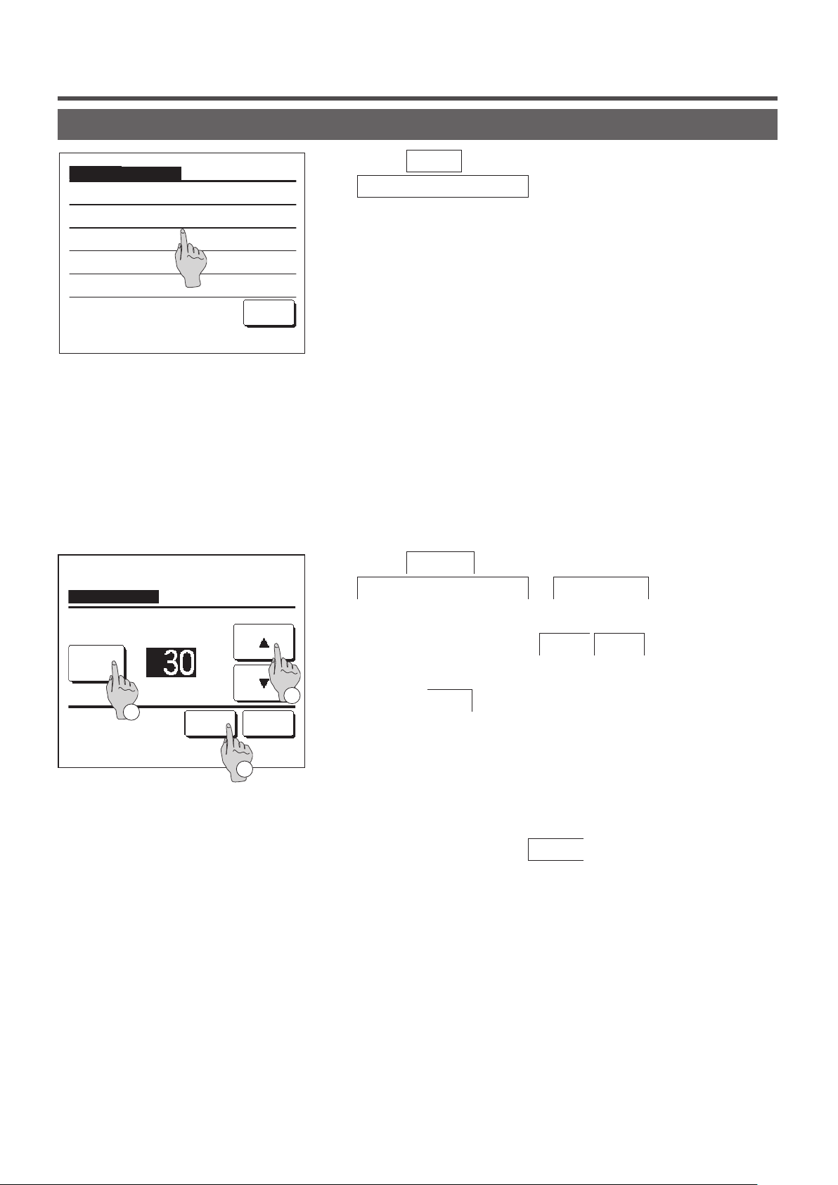
1
Tap the
Menu
Energy-saving setting
screen is displayed.
When the Energy-saving setting screen is displayed, select a desired
2
button on the TOP screen and select
. The Energy-saving setting menu
item.
Back
Select the item.
・Sleep timer ……☞page 21
・Peak-cut timer ……☞page 22
・Automatic temp set back ……☞page 25
Infrared sensor control ……☞page 26
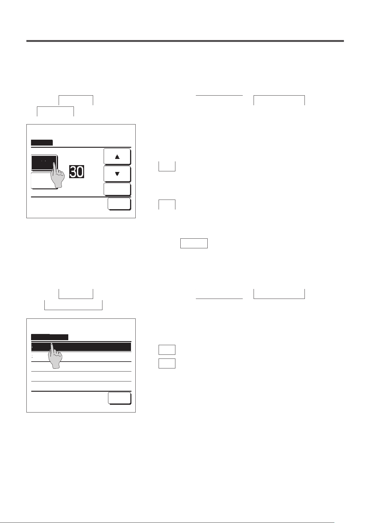
■Sleep timer
Stops operation when the amount of time set has elapsed since the start of each operation.
Sleep timer
A/C will stop at the set minutes later.
Tap the
1
Energy-saving setting ⇒ Sleep timer
screen is displayed.
Menu
button on the TOP screen and select
. The Sleep timer
State
Disable
2
Tap ▲▼ to set the minutes & tap [Set].
min.
Set Back
Select a desired time with ①
2
▲
▼
buttons.
Setting range: 30 to 240 minutes, at 10-min intervals.
1
Tap the ②
3
button to switch between “State Enable” and
State
“State Disable”.
“Enable”: operation stops at the set time every time.
3
・
“Disable”: the sleep timer does not operate.
・
Unless the Sleep timer is used, set at the “State Disable”.
After the setting, tap the ③
4
button. The display returns to
Set
the Energy-saving setting menu screen.
- 21 -
Page 24
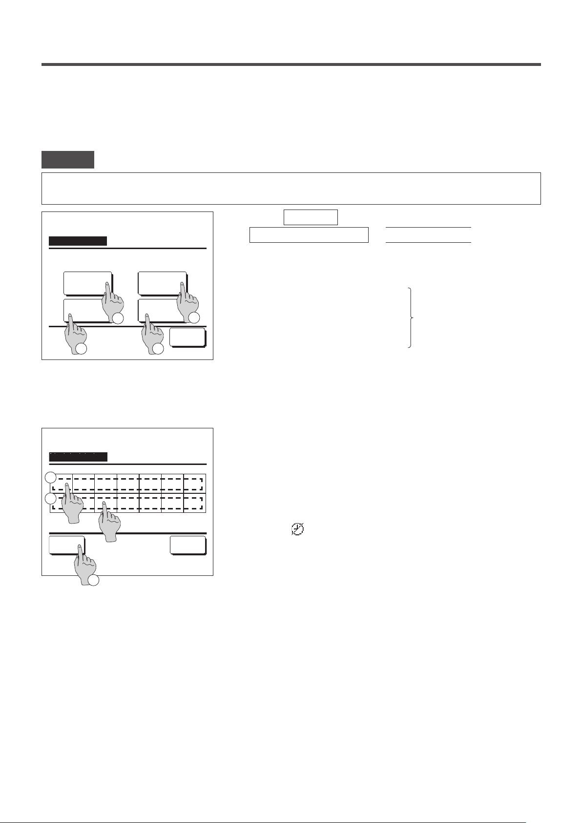
■Peak-cut timer
Set the times to start and stop the capacity (upper limit) limiting operation and the peak-cut %.
Advice
· When the peak-cut timer is used, be sure to make the Clock setting in advance (☞page 33).
· The peak-cut timer control may not be performed depending on combination of IU and OU.
Peak-cut timer
Select the item.
Sat, SunWeekdays
All days
3
Peak-cut timer
1
Mon Tue Wed Thu Fri Sat Sun
2
Invalid Setting:Tap box below day of week.
If invalid is selected, timer won't start
All Disable
Select the day of the week.
1
3
Each day
4
Back
Back
1
Tap the
Menu
Energy-saving setting ⇒ Peak-cut timer
button on the TOP screen and select
.
When the setting range selection screen for the peak-cut timer is
displayed, select the day of the week to be set.
Weekdays : Monday - Friday
①
2
Sat. Sun : Saturday, Sunday
②
All days : Monday - Sunday
③
Each day : Moves to the day of the week setting screen. (☞2)
④
If a desired day of the week ① is tapped on the display, contents of
2
(☞
current setting for the day are displayed.
4)
(☞5)
For the holiday setting, tap the block ② under a day to switch
3
between “
” (the holiday setting) and “(Blank)” (reset).
Timer does not operate on the day set as holiday.
Two or more holidays can be set.
■To enable the timer on the day set as holiday, it is necessary to reset the holiday
setting.
When tapping ③ “All Disable” button, the timer does not operate on
4
all days of the week.
When the timer is used, be sure not to set “All Disable”.
- 22 -
Page 25
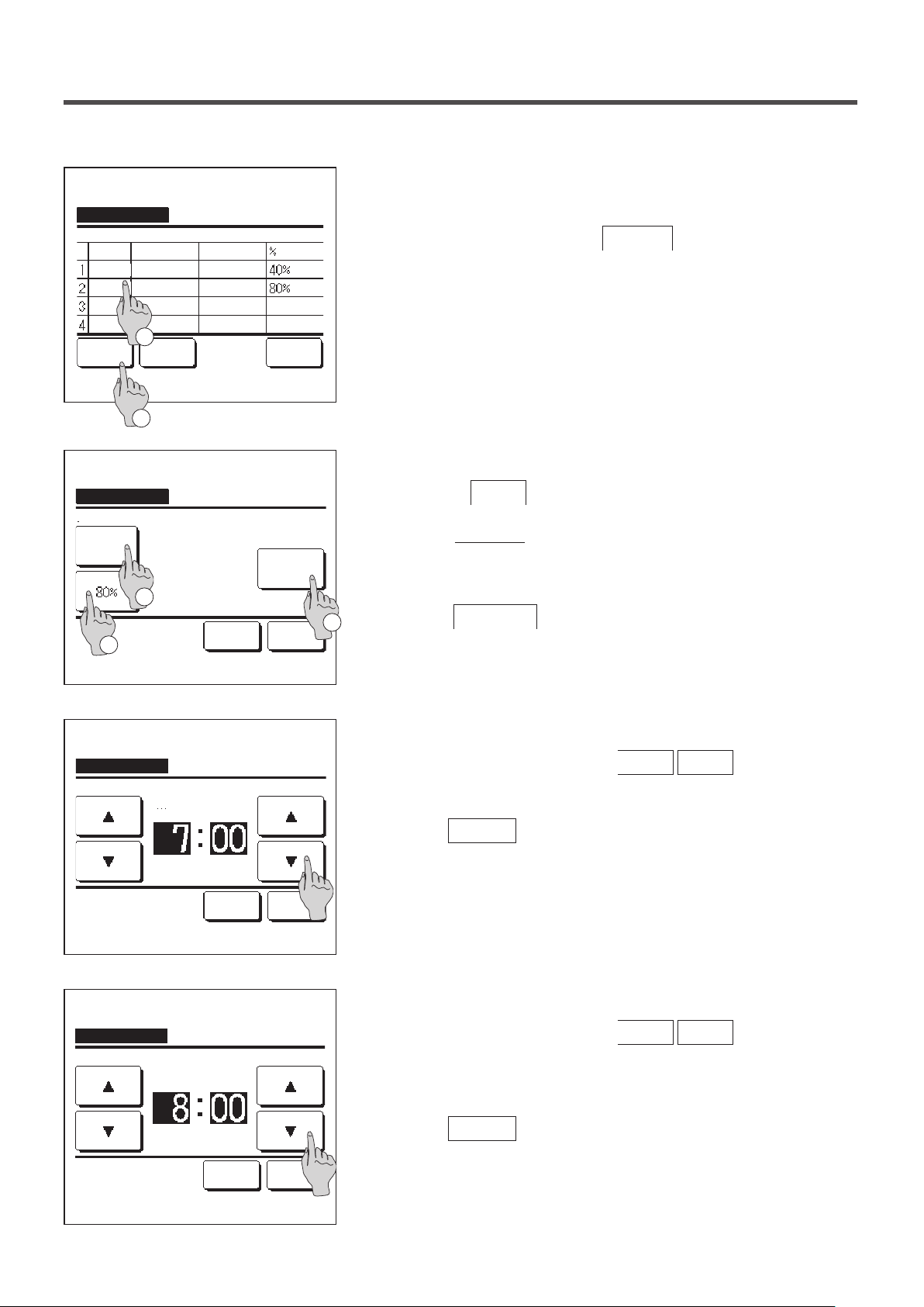
Screen to check contents of current setting is displayed.
5
Peak-cut timer
Mon
State
Start time End time
Enable
7:00 PM
7:00 AM
Disable
Disable
Disable
Change
Select a line & tap [Change].
Peak-cut timer
Mon: No.1
Disable
Select the item.
State
3
1
Enter Back
2
Start time
7:00 AM
End time
8:00 AM
1
8:00 PM
8:00 AM
Set Back
Change
When the contents are changed or new setting is added, select a ①
setting line No. and tap the ②
Detail setting screen for the timer setting contents is displayed.
6
Tap the
①
button to switch between “State Enable” and
State
Change
button.
“State Disable”.
②
If the
Change
button is tapped, the start time and the end time
can be set. (☞7)
If the
2
③
Peak-cut
button is tapped, the peak-cut % can be set. (
☞
9)
Peak-cut timer
Mon: No.1
Tap ▲▼ to set clock time & tap [Set].
Peak-cut timer
Mon: No.1
Tap ▲▼ to set clock time & tap [Set].
Start time
AM
Set Back
End time
AM
Set Back
Set the Start time.
7
Set the hour and minute with the
▲
▼
buttons.
Setting time can be set at 5-min intervals.
Tap the
Set the End time.
8
Set the hour and minute with the
button after the setting. (☞8)
Set
▲
▼
buttons.
End time can be set from 5 minutes after the Start time up to 24:00
at 5-min intervals
Tap the
button after the setting.
Set
(☞10)
- 23 -
Page 26

Peak-cut timer
Wed: No.1
Peak-cut
Set the peak-cut %.
9
Set the peak-cut % with the
▲ ▼ buttons.
The peak-cut % can be set at 0%, 40%, 60% or 80%.
The lower the peak-cut % is, the higher the effect of
energy-saving becomes.
to set peak-cut & tap [Set]
Tap ▲▼
Peak-cut timer
Mon: No.1
State
Disable
Select the item.
Peak-cut timer
Weekdays
State
Enable
Disable
Disable
Disable
Change
Select a line & tap [Change].
Start time
7:00 AM
End time
8:00 AM
Start time End time
7:00 PM
7:00 AM
Enter Back
Set Back
Set Back
8:00 PM
8:00 AM
Change
Tap the
Set
button after the setting.
(☞10)
The setting content check screen (☞6) is displayed. If the
10
Set button is tapped, the contents are confirmed and a day
of the week setting content check screen (☞5) is displayed.
If the settings are corrected or added further within the same day,
11
repeat the setting. (☞5)
■When contents of the setting are duplicated, the priority is given to the set
contents of smaller peak-cut %.
Display a day of the week setting content check screen. To save
12
the setting, tap the
a) In case of group setting: (1-①Weekdays, 1-②Sat, Sun, 1-③
Enter button.
All days) Move to the group setting check screen. (☞13)
b) In case of individual setting: (1-④Each day) Save the setting
and move to a day of the week selection screen (☞2)
Peak-cut timer
Do you want to apply group setting?
Yes
Back
Display the group setting acknowledge screen.
13
Tap the Ye s button to save the setting.
The display changes to a day of the week setting check screen
after the saving. (☞2)
When making the setting after changing a day of the week, repeat
14
the setting from the step 2.
- 24 -
Page 27

■Automatic temp set back
It returns to the set temperature when the set time is counted up.
Automatic temp set back
Setting in cooling
Setting in heating
Tap the
1
Energy-saving setting
Automatic temp set back screen is displayed.
Tap
Menu button on the TOP screen and select
Setting in cooling
⇒
Automatic temp set back
. The
when setting for the cooling operation or
Select the item.
Setting in cooling
min.
°C
Back
Setting in heating
when setting for the heating operation.
The Setting in cooling operation includes the cooling, dry and auto.
The Setting in heating is for the heating operation only.
Setting time range: 20 - 120 min, at 10-min intervals
Set temp range: It can be set within the preset temp range set
according to the set temp range menu.(☞page
54)
Set desired time and temperature with the
2
When the
button is tapped, contents of setting are
Set
▲ ▼ buttons.
conrmed, and the display returns to the last previous screen.
When the
No setting
button is tapped, “
--
min. --°C” is
displayed, and the “Automatic temp set back” is not performed.
No setting
Set the time & temp to return.
Setting in heating
min.
No setting
Set the time & temp to return.
Set Back
°C
Set Back
The same setting method as the Setting in the cooling operation can
3
be applied to the Setting in heating.
- 25 -
Page 28

■
Infrared sensor (motion sensor) control (for IUs with motion sensors)
Presence of humans and the amount of motion are detected by a motion sensor to perform various controls.
■When the R/C is set as the sub R/C, the infrared sensor (motion sensor) control cannot be set.
Infrared sensor control
Power control
Auto-off
Select the item.
20:20
(Tue)
Heating
Timer
Set temp
EnableDisable
EnableDisable
1
Set Back
3
Direction
2
Menu
1
Tap the
Menu
button on the TOP screen and select
Energy-saving setting ⇒ Infrared sensor control
The Infrared sensor control screen and contents of the current
settings are displayed.
Enable/disable power control.
①
Enable/disable auto-off.
②
After you set each item, tap the
③
Set
button.
The display returns to the Energy-saving setting menu screen.
・When power control is enabled
The amount of human motion is detected by a motion sensor to
adjust the Set temp.
During power control, “Power control ON” will be displayed on the
message display.
.
Power control ON
F1: High power F2: Energy-saving
16:32
(Mon)
Cooling
Timer
In auto-off mode
F1: High power F2: Energy-saving
Set temp
Direction
・ When auto-off is enabled
Menu
The unit will enter the “Operation wait” state when an hour has
elapsed since the last time a human presence was detected and
will be in “Complete stop” state after another 12 hours.
"Operation wait"... The unit stops but will resume operation when
human presence is detected.
When the unit is in “Complete stop”, “In auto-off
mode” will be displayed on the message display.
"Complete stop"... When auto-off is enabled, the unit stops.
The unit will not resume operation even when
human presence is detected.
The message “In auto-off mode” will disappear
from the message display, and the operation
- 26 -
lamp will turn off.
Page 29

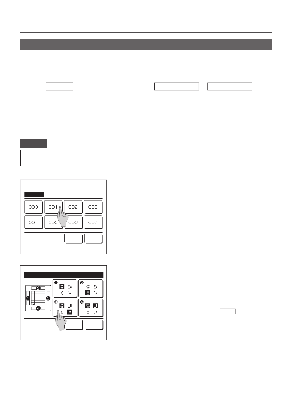
Individual flap control
Motion range (upper, lower, left, or right limit positions) of the flap at each blow outlet can be set to a desired range.
■When the R/C is set as the sub R/C, the individual flap control cannot be set.
1
Tap the
tap the
Menu
Change flap direction
button on the TOP screen and select
button on the TOP screen and select
Useful functions ⇒ Individual flap control
Ind. flap control
, and then enter the
administrator password.
When one IU is connected to the R/C: ☞3
When two or more IUs are connected to the R/C: ☞2
Advice
・Individual flap control should be set when the unit is stopped.
・When you perform Individual flap control while the unit is in operation, the acknowledge screen for unit stop is displayed.
When two or more IUs are connected to the R/C, a list of IUs is
2
IU select
displayed. Tap the IU to be set.
, or
Select an IU address.
Next Back
- 27 -
Page 30

№③
ドレンホース側
[FDTの場合]
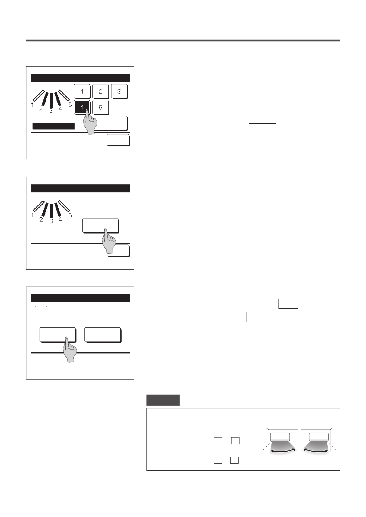
Individual flap control Select flap
Select the number of the ap of which the motion range is changed.
3
(☞4)
Bat.set. Back
Flap ❶ is in operation.
Individual flap control Select flap
■When there are two or more flaps at the blow
outlet, such as the FDT type, the flap at blow
outlet No. ① will keep moving while the blow
outlet selection screen is displayed. The figure
displayed on the screen shows the installed
unit viewed from the floor side. Select the flap
based on this figure. When you have selected
the blow outlet, the flap with the number you
selected will move.
■You can set all flaps at once by tapping the
Bat.set.
button (except for FDKs with a left/
right flap).
■When there is only one flap at the blow outlet,
such as the ceiling suspended type only the
flap that can be set will be displayed.
№①
配管側
Pipe side
№②
Control box
制
御
箱
№④
Drain hose side
Louver No.
ルーバ№
[For FDT]
For an FDK with a left/right ap, select the upper/lower ap or left/
right ap.
When you select the upper/lower ap (①): ☞4
When you select the left/right ap (②): ☞8
Flap❶ Swing range
Upper limit setting
Select the upper limit No. & tap [Set].
Set
Back
Back
Select one of the upper limit positions from
4
motion range.
After you select the range, tap the
Set
1 to 6 for the flap
button.
- 28 -
Page 31

Flap❶ Swing range
Select one of the lower limit positions from
5
1 to 6 for the flap
motion range.
The range of motion between the upper and lower limit positions will
be displayed in black.
Lower limit setting
Select the lower limit No. & tap [Set].
Flap❶ Swing range
Do you want to set the
range of flap motion?
If yes, tap [Yes].
Tap [Back] for resetting.
Flap❶ setting is completed
Setting the range of flap❶
motion is complete.
Do you want to set other flaps?
Yes
Yes
No
Set
Back
Back
After you select the range, tap the
Acknowledge screen for the flap motion range is displayed.
6
Acknowledge screen for the completion of setting is displayed.
7
To change other ap motion ranges, tap the
To terminate the setting, tap the
No
button.
Set
button (☞3).
Yes
button. The display returns
to the TOP screen.
Tap [No] to return to top screen.
[When left/right ap is selected for an FDK with a left/right ap]
Select one of the left limit positions from
8
Flap❷ Swing range
motion range.
After you select the range, tap the
Left limit setting
Select the left limit and tap [Set].
Set
Back
- 29 -
Set
to 5 for the ap
1
button.
Page 32
Flap❷ Swing range
Right limit setting
Select the right limit and tap [Set].
Flap❷ Swing range
Do you want to set the
range of flap motion?
If yes, tap [Yes].
Yes
Set
Back
Select one of the right limit positions from
9
to
1
for the ap
5
motion range.
The range of motion between the left and right limit positions will be
displayed in black.
After you select the range, tap the
Acknowledge screen for the flap motion range is displayed.
10
Set
button.
Tap [Back] for resetting.
Flap❷ setting is completed
Setting the range of flap❷
motion is complete.
Do you want to set other flaps?
Yes
Tap [No] to return to top screen.
No
Back
Acknowledge screen for the completion of setting is displayed.
11
To change other flap motion ranges, tap the Ye s button. (☞3)
To terminate the setting, tap the No button. The display
returns to the TOP screen.
Advice
When the unit is installed within 50 cm from a wall, it is recommended that you change
the range of the left/right flap motion as follows:
・ When installed at the right end of the wall
1
Left/right flap motion range
・ When installed at the left end of the wall
Left/right flap motion range
4
to
2
to
5
Installed at
the left end
Installed at
the right end
- 30 -
Page 33
Anti draft setting (for using panel with anti draft)
You can enable/disable the motion of panel with anti draft for each blow outlet for each operation mode.
■When the R/C is set as the sub R/C, the anti draft setting cannot be set.
1
Tap the
Menu
button on the TOP screen and select
Useful functions ⇒ Anti draft setting
When one IU is connected to the R/C: ☞3
When two or more IUs are connected to the R/C: ☞2
■ Depending on how the Permission/Prohibition setting (☞page 52) is set, the administrator password input screen may be
displayed.
Advice
・Anti draft setting should be set while the unit is stopped.
・ When you perform Anti draft setting while the unit is in operation, the acknowledge screen for unit stop is displayed.
When two or more IUs are connected to the R/C, a list of IUs is
2
IU select
displayed. Tap the IU to be set.
.
Select an IU address.
Flap selection for anti draft setting
Bat.set. Back
Flap ❶ is in operation
Next Back
Select the blow outlet number to set anti draft.
3
■ The flap at blow outlet No. ① will keep moving while the blow outlet selection
screen is displayed. Select the flap based on this figure. When you have
selected the blow outlet, the flap with the number you selected will move. The
figure displayed on the screen shows the installed unit viewed from the floor
side.
Bat.set.
■You can set all blow outlets at once by tapping the
button.
An icon that indicates the operation mode (☞page 9) is shown
on each blow outlet button.
When the anti draft setting is enabled, the icon color will be reversed
(for example, in the left gure, blow outlets which have the anti draft
setting enabled during cooling are numbers ①, ③, and ④).
- 31 -
Page 34
Select enable/disable for each operation mode.
4
Anti draft setting mode setting
Select the item.
DisableCooling
DisableHeating
DisableFan
DisableDry
Set Back
Enable
Enable
Enable
Enable
After you make the selection, tap the
The display returns to the blow outlet selection screen.
Set
button.
Ventilation operation (when ventilation device is installed)
The ventilation is turned on or off if the ventilation device is installed.
Tap the
1
■The ventilation operation is enabled in case that the External ventilation is set “Independent” (refer to the installation manual for
details).
■In case that the External ventilation is set “Disable” or “Interlocking” the ventilation operation is disable.
Menu
button on the TOP screen and select
Useful functions ⇒ External ventilation
.
External ventilation
Venti. ON
Select Venti. ON/OFF.
Venti. OFF
Back
The External ventilation screen is displayed.
2
If the
Venti. ON
To stop the ventilation operation, tap the
■In case that the Ventilation is set “Interlocking”, the ventilation operates
interlocked with Run/Stop operation of air conditioner (refer to Installation
Manual).
button is tapped, the ventilation operation starts.
Venti. OFF
button.
- 32 -
Page 35
Initial settings
Tap the
1
Initial settings
Clock setting
Date & time display
Summer time
Contrast
Backlight
Select the item.
Initial settings
Controller sound
Operation lamp luminance
Menu
button on the TOP screen and select
When the “Initial settings” menu screen is displayed, tap a desired
2
item.
Clock setting ……☞ page 33
・
Date & time display ……☞ page 34
・
Summer time ……☞ page 35
・
Contrast ……☞ page 35
・
Backlight ……☞ page 36
Next Back
・
Controller sound ……☞ page 36
・
Operation lamp luminance ……☞ page 37
・
User setting ⇒ Initial settings
.
Previous Back
Select the item.
■Clock setting
You can set and correct the current date and time.
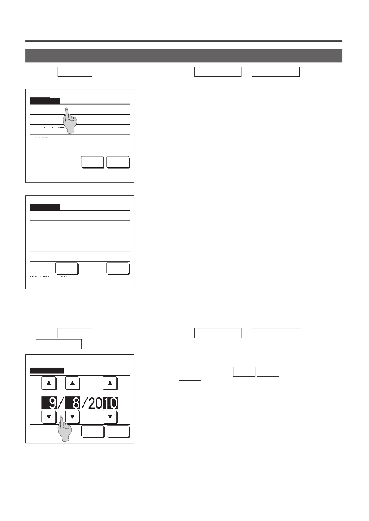
1
Tap the
Menu
Clock setting
button on the TOP screen and select
.
2
Clock setting
dd
Set the date.
mm
Time Back
yy
User setting ⇒ Initial settings ⇒
The “Clock setting” screen is displayed.
Set the “dd/mm/yy” with the
Tap the
■The “clock setting” is necessary for the following settings.
· Peak-cut timer
· Set ON timer by clock, Set OFF timer by clock
· Weekly timer
· Outdoor unit silent mode timer
· Filter sign reset, Setting next cleaning date
button after the setting.
Time
▲
▼
buttons.
- 33 -
Page 36
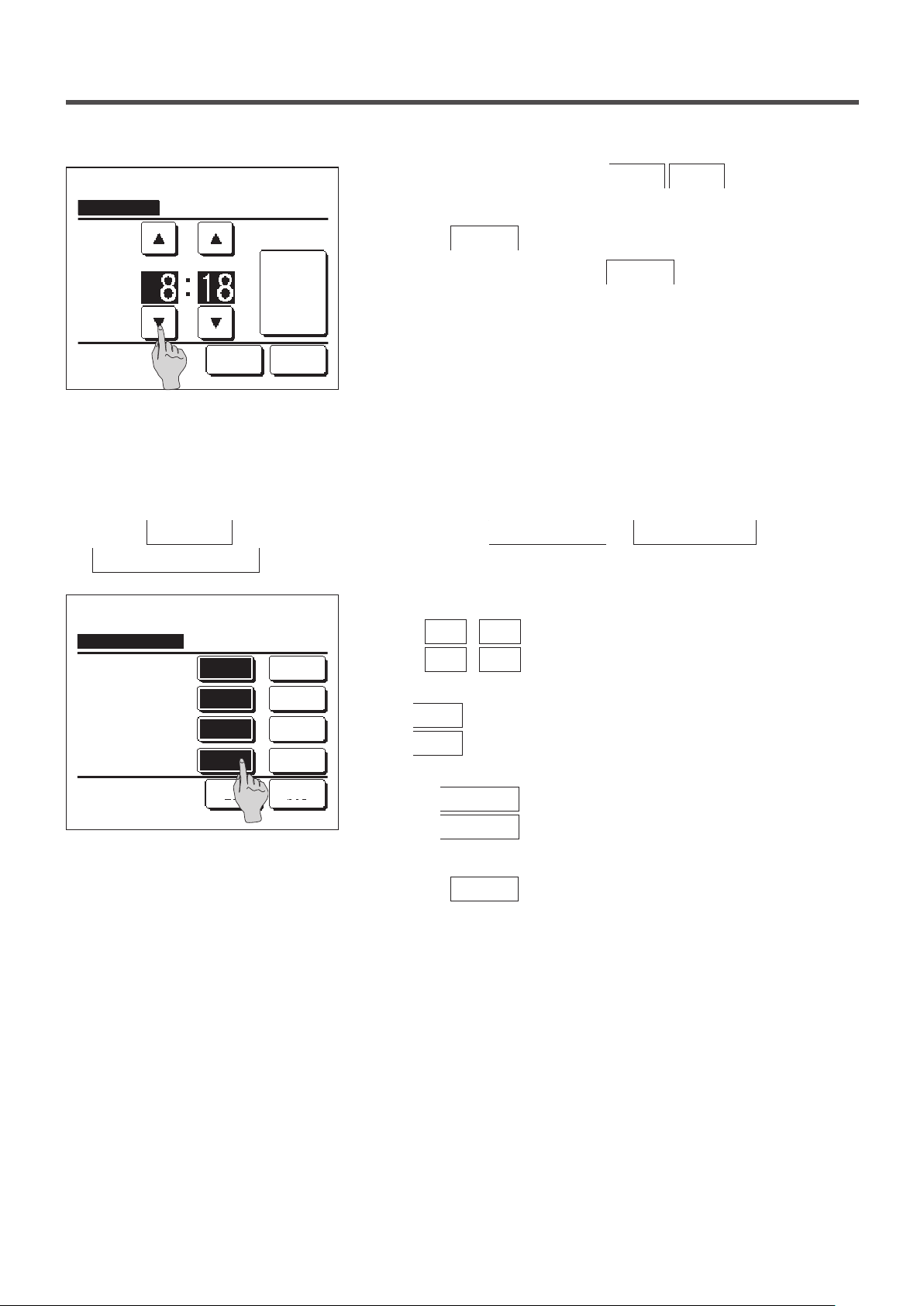
3
Clock setting
PM
Set
Set the time.
Date Back
■Date & time display
You can set and correct the date & time display.
Tap the
1
Date & time display
Menu
button on the TOP screen and select
.
2
Date & time display
Position of AM / PM
Select setting
ONDate & time
ONA day of the week
12HDisplay method
Infront
Set Back
OFF
OFF
24H
Back
Set the “hour : minute” with the
▲
clock setting screen.
Tap the
Set
To change “dd/mm/yy” tap the
button after the setting.
Date
User setting ⇒ Initial settings ⇒
The Clock setting screen is displayed.
Tap
Tap
OFF
OFF
/
/
for the Date and time.
ON
for A day of the week.
ON
Tap Display method “12H or 24H”.
Hours … If it is 3:50 PM, it displays “3:50PM”.
12H
Hours … If it is 3:50 PM, it displays “15:50”.
24H
Set the position of AM/PM.
Set
Set
Infront
Back
... “PM3:50” is displayed.
... “3:50PM” is displayed.
▼
button.
buttons on the
3
Tap the
- 34 -
Set
button after the setting.
Page 37
■Summer time
You can adjust the current time by one hour.
Tap the
1
Summer time
Summer time
Enable
Disable
Select the item.
Menu
button on the TOP screen and select
.
Back
■Contrast
You can adjust the contrast of the LCD.
1
Tap the
Contrast
Contrast
Menu
.
Dark
button on the TOP screen and select
Adjust
User setting ⇒ Initial settings ⇒
The Summer time setting screen is displayed.
2
Changing from
Disable
to
Enable
… (Current time + 1 hr) is
displayed.
Changing from
Enable
to
Disable
… (Current time – 1 hr) is
displayed.
User setting ⇒ Initial settings ⇒
The Contrast Adjustment screen is displayed.
2
Tap the “Contrast” on the Initial settings menu screen. The contrast
on the screen changes by tapping the
Dark
or
Bright
select a desired contrast.
button to
Set
Bright
Back
3
Tap the
Set
[When the contrast differs between the top and bottom of the screen]
Upper/Lower Contrast
Adjust contrast between upper and lower.
Dark
Bright
Set
Back
Tap the
4
screen.
The contrast of the lower half of the screen changes when you tap
5
the
and lower halves of the screen match.
After you make the settings, tap the
6
Adjust button to display the Upper/Lower Contrast
/
Dark
Bright
- 35 -
button after the setting.
button. Adjust the contrast so that the upper
button.
Set
Page 38
■Backlight
You can turn ON/OFF the backlight and set the lighting period.
1
Backlight
Tap the
Backlight
Menu
.
button on the TOP screen and select
The Backlight setting screen is displayed.
2
Tap the ON or OFF buttons for the backlight lighting and the lighting
User setting ⇒ Initial settings ⇒
Period (5 - 90 sec, at 5-sec intervals).
ON
OFF
Select the item.
Seconds
Set
Back
3
… The “Backlight” lights when the LCD is tapped.
ON
If no operation is made for the set time, it turns off
automatically.
… The “backlight” does not light even if the LCD is tapped.
OFF
Tap the
Set button after the setting.
■Controller sound
You can set to have the controller sound ON/OFF when the touch panel is operated.
1
Tap the
Menu
⇒ Controller sound
Controller sound
ON
OFF
Select the item.
button on the TOP screen and select
.
The Controller sound setting screen is displayed.
2
Tap ON or OFF for the controller sound.
… When a button on the screen is tapped, a “beep” sounds.
ON
… There is no beep.
OFF
Back
User setting ⇒ Initial settings
- 36 -
Page 39

■Operation lamp luminance
You can adjust the operation lamp luminance.
1
Tap the
Menu
Operation lamp luminance
Operation lamp luminance
Use ▲▼ to adjust light and dark.
button on the TOP screen and select
.
2
Light
▲
3
▼
Set
Dark
Back
User setting ⇒ Initial settings ⇒
The Operation lamp luminance adjustment screen is displayed.
You can adjust the luminance of the operation lamp to a desired
level by tapping the
▲ Light
After you make the settings, tap the
/
▼ Dark
Set
Timer
Advice
· The Clock setting (☞page 33) must be made when the Set ON timer by clock or Set OFF timer by clock is used.
button.
button.
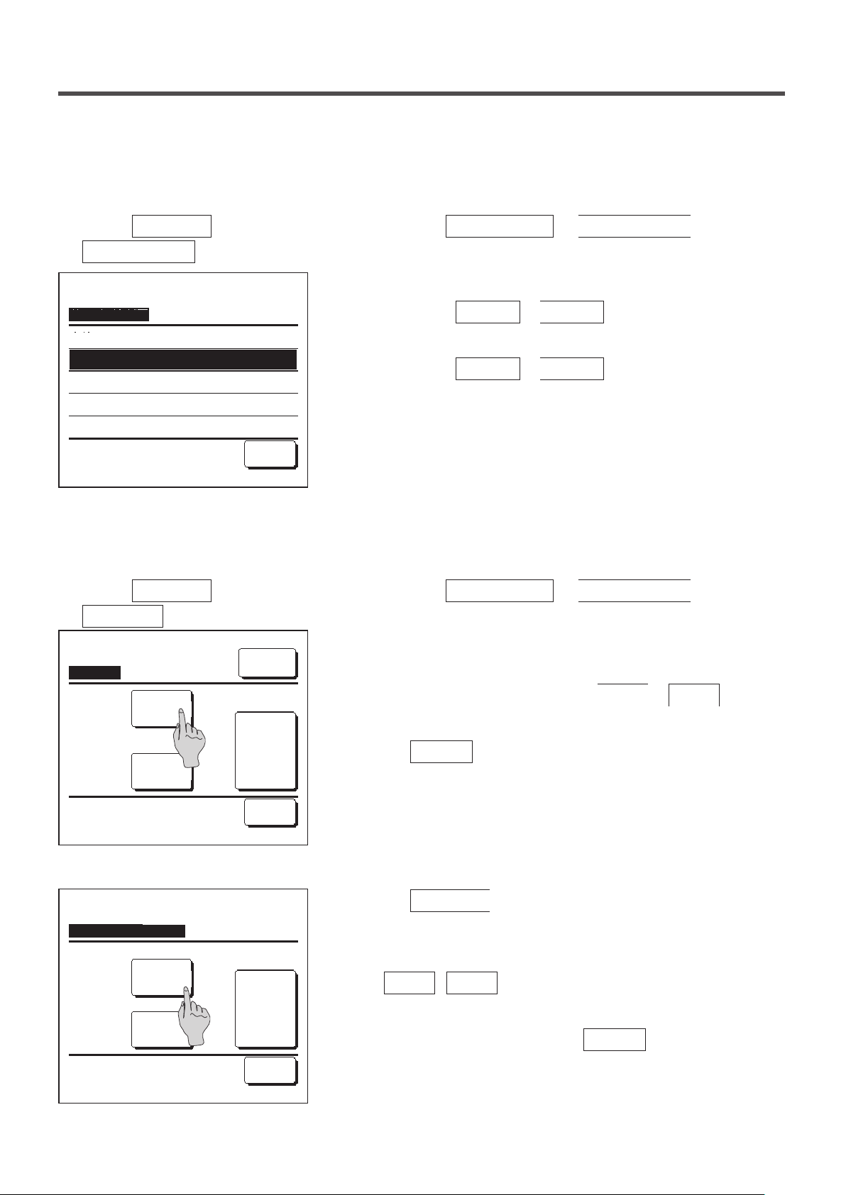
Tap the
1
Timer
Set ON timer by hour
Set OFF timer by hour
Set ON timer by clock
Set OFF timer by clock
Select the item.
Menu
button on the TOP screen and select
Tap a desired item on the Timer menu.
2
Set ON timer by hour ……☞page 39
・
Set OFF timer by hour ……☞page 40
・
Set ON timer by clock ……☞page 41
・
Set OFF timer by clock ……☞page 41
・
Conrm ……☞page 42
・
Confirm Back
When the timer is set, the
The button is not displayed unless the timer is set.
Useful functions ⇒ Timer
Confirm
button is displayed.
- 37 -
Page 40
■Operation of each timer
・Sleep timer (☞page 21)
Stops the operation of the unit when the amount of time set has elapsed since the start of the operation. When the setting is enabled,
this timer will activate whenever any operation starts.
・Set ON timer by hour (☞page 39)
When the set time elapses, the air conditioner starts.
Operating conditions at the start of operation can be set.
Operation takes place once at each setting.
・Set OFF timer by hour (☞page 40)
When the set time elapses, the air conditioner stops.
Operation takes place once at each setting.
・Set ON timer by clock (☞page 41)
The air conditioner starts at the set time.
Operating conditions at the start of operation can be set.
Only one day (Once) operation or operation Everyday can be set.
・Set OFF timer by clock (☞page 41)
The air conditioner stops at the set time.
Only one day (Once) operation or operation Everyday can be set
・Weekly timer (☞page 42)
On timer and Off timer on weekly basis can be set.
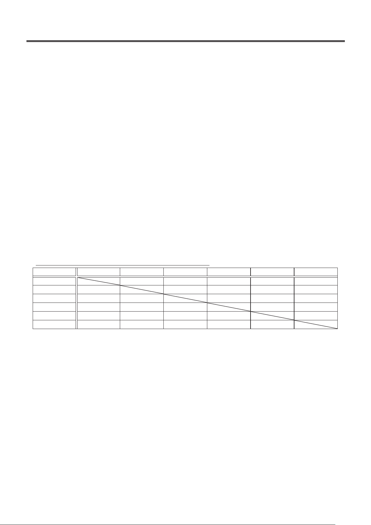
■Setting of each timer can be combined. Allowable combination settings are as shown below.
Allowable combination setting (○: Allowed, ╳: Prohibited)
Sleep OFF: Hours ON: Hours OFF: Clock ON: Clock Weekly
Sleep × × ○ ○ ○
OFF: Hours × × × × ×
ON: Hours × × × × ×
OFF: Clock ○ × × ○ ×
ON: Clock ○ × × ○ ×
Weekly ○ × × × ×
If a prohibited combination setting is made, a message “The combination can't be accepted” is displayed for 3 seconds.
■Priority order of the timer settings (①→③) is as follows.
① Set OFF timer by hour/clock, weekly OFF timer
② Sleep timer
③ Set ON timer by hour/clock, weekly ON timer
■On the TOP screen, the timer is displayed from the earliest one out of OFF time of the sleep timer, ON time and OFF time.
- 38 -
Page 41
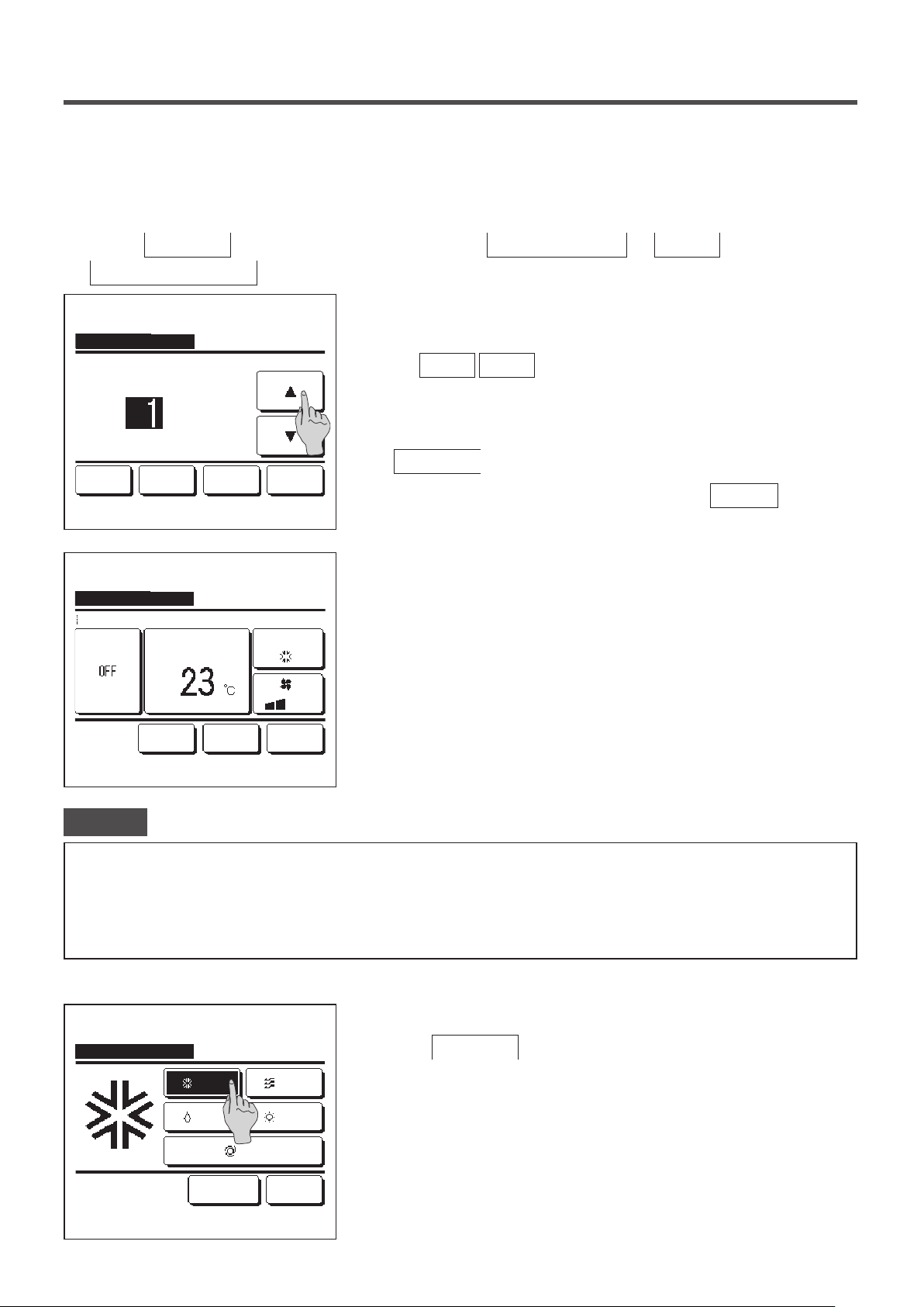
■Set ON timer by hour
When the set time elapses, the air conditioner starts.
1
Tap the
Menu
Set ON timer by hour
Set ON timer by hour
A/C will start at the set hours later.
hours
CancelNext
Tap ▲▼ to set clock time & tap [Set].
Set ON timer by hour
Details
Warming up
Set temp
button on the TOP screen and select
.
The Set ON timer by hour setting screen is displayed.
2
Select desired hours for the period to start operation by timer with
the
▲
Range of setting time: 1 to 12 hours (at 1-hr intervals)
When operating conditions at the start of operation are set, tap the
3
Next
Set Back
When operating conditions are not set, tap the
Set the following operating conditions.
4
Warming up ON/OFF (the Main R/C only)
①
Operation mode … ☞5
Cooling
②
Set temp … ☞6
③
Useful functions ⇒ Timer ⇒
▼
buttons.
button. (☞4)
Set
button.
Fan speed … ☞7
④
Previous
Select the item to change.
Set Back
■Warming up setting can be made with the main R/C only.
■Set the operation mode before setting the set temperature.
Advice Warming up
· To warm up the room temperature closed to the set temperature at the set start time of the operation, the microcomputer estimates the
start time of the operation based on the last warming up operation and starts the operation 5 to 60 minutes earlier.
· When the warming up is turned ON, set the timer at one hour earlier or more than the start operation by timer.
If it is set in less than one hour, a message “Warming up cancelled” is displayed on the screen. (This is used as the Set ON timer by hour
and clock.)
Tap a desired operation mode.
5
Set ON timer by hour
Cooling
Dry
Fan
Heating
If the
No setting
action. (☞4)
button is tapped, it starts operation at the last
No setting Back
Please select operation mode.
Auto
- 39 -
Page 42

Set ON timer by hour
Auto
Select a desired temperature (at 1°C intervals) with the
6
▲
buttons. Or tap the
▼
button and select the
Auto
auto temp setting.
Tap the
Set
button after the adjustment. (☞4)
Tap
to set temp & tap [Set].
▲▼
Set ON timer by hour
Select the fan speed.
Set
No setting Back
Auto
No setting Back
When the
No setting
button is tapped, “
--
°C” is displayed, and it
starts operation at the last setting temperature.
Tap a desired fan speed.
7
If the
No setting
button is tapped, it operates at the last action. (
4)
After setting the desired contents at the screen of the step 4 on the
8
previous page, tap the
Set
button.
Operation will start at set hours later.
☞
■Set OFF timer by hour
When the set time elapses, the air conditioner stops.
1
Tap the
Menu
Set OFF timer by hour
Set OFF timer by hour
A/C will stop at the set hours later.
hours
Cancel
Tap ▲▼ to set clock time & tap [Set].
button on the TOP screen and select
.
The Set OFF timer by hour setting screen is displayed.
2
Select desired hours to stop operation with the
buttons.
Range of setting time: 1 to 12 hours (at 1-hr intervals)
Tap the
3
Set Back
Useful functions ⇒ Timer ⇒
Set
button after the setting.
▲
▼
- 40 -
Page 43

■Set ON timer by clock
Starts the operation of the unit at the set clock time.
1
Tap the
Menu
Set ON timer by clock
Set ON timer by clock
A/C will start at the set clock time.
Once
CancelNext
Tap ▲▼ to set clock time & tap [Set].
button on the TOP screen and select
.
The Set OFF timer by hour setting screen is displayed.
2
Select a desired time to start operation (5-min intervals) with the
▲
AM
When operating conditions at the start of operation are set, tap the
3
Next
The operation conditions can be set the same way as the Set ON
Set Back
timer by hour settings (☞page 39 4 to 7)
If operating conditions are not set, tap the
The Set ON timer by clock can be operated one day (Once) or
everyday.
If it is operated everyday, tap the
change the display to “Everyday”.
Useful functions ⇒ Timer ⇒
buttons.
▼
button to set operation conditions.
Once
Set
/
Everyday
button.
button to
■Set OFF timer by clock
Stops the operation of the unit at the set clock time.
1
Tap the
Menu
Set OFF timer by clock
Set OFF timer by clock
A/C will stop at the set clock time.
Once
Cancel
Tap ▲▼ to set clock time & tap [Set].
button on the TOP screen and select
.
The Set OFF timer by clock setting screen is displayed.
2
Select a desired time to stop operation (5-min intervals) with the
AM
3
Tap the
The Set OFF timer by clock can be operated one day (Once) or
everyday.
Set Back
If it is operated everyday, tap the
change the display to “Everyday”.
▲
/
Everyday
button to
Useful functions ⇒ Timer ⇒
buttons.
▼
button after the setting.
Set
Once
- 41 -
Page 44

■Confirm
Confirm
Timer type
OFF:Hours
ON:Hours No setting
OFF:Clock No setting
ON:Clock No setting
Weekly
Sleep 240min. OFF
Setting status
No setting
(Wed) ON
5:00 PM
Back
When you tap the
1
the contents of the current timer settings are displayed.
■When the warming up is set,
confirmation screen.
Confirm
Weekly timer
You can set four on timer and off timer operations for each day of the week.
Advice
· The Clock setting (☞page 33) must be made when the weekly timer is used.
· The weekly timer can be set from the main R/C only.
button on the Timer menu screen,
“ ”
is displayed in front of the operation mode on
1
Tap the
Menu
button on the TOP screen and select
Useful functions ⇒ Weekly timer
Enter the administrator password if the administrator password input screen is displayed.
■There are cases that the Input password screen is displayed by the Permission/Prohibition setting.
(☞page 53)
When the screen to select the setting range, select a day of the
2
Weekly timer
Select the item.
All days
3
Sat, SunWeekdays
1
Each day
4
2
Back
week to be set.
Weekdays : Monday - Friday
①
Sat. Sun : Saturday, Sunday (☞5)
②
All days : Monday - Sunday
③
Each day : Moves to the day of the week setting screen. (☞3)
④
.
- 42 -
Page 45

Weekly timer
When a desired day of the week ① is tapped on the display,
3
contents of current setting for the day are displayed. (☞5
)
1
Mon Tue Wed Thu Fri Sat Sun
2
Invalid Setting:Tap box below day of week.
If invalid is selected, timer won't start
All Disable
Select the day of the week.
3
Weekly timer
Weekdays
State
Type Time
Enable
Enable
Enable
Enable
1
Change
Select a line & tap [Change].
11:00 AM
ON
0:00 AM
ON
0:00 AM
OFF
0:00 AM
ON
Enter Back
Mode Fan Temp
Next
Back
AutoAuto
For the holiday setting, tap the block ② under the day to switch
4
between “ ” (the holiday setting) and “(Blank)” (reset).
Timer does not operate on the day set as holiday.
Two or more holidays can be set.
■To enable the timer on the day set as holiday, it is necessary to reset the holiday
setting.
When tapping ③ “All Disable” button, the timer does not operate on
all days of the week.
When the timer is used, be sure not to set “All Disable".
Screen to check contents of current setting is displayed.
5
When the contents are changed or new setting is added, select a ①
setting line No. and tap the ②
Change
button.
2
Weekly timer
Weekdays:No.1
State
Enable
Type
ON
1
Next
2
Tap ▲▼ to set clock time & tap [Set].
Set Back
AM
Detail setting screen for the timer setting contents is displayed.
6
Tap the
①
button to switch between “State Enable” and
State
“State Disable”.
Tap the
②
3
the “ON timer”.
Select a desired time (at 5-min intervals) with the
③
▲
In case of “ON timer” when the
④
button to switch between the “OFF timer” and
Type
buttons.
▼
button is tapped,
Next
operating conditions at the start of operation can be set. (☞7)
- 43 -
Page 46

Weekly timer
Details
Warming up
Previous
Select the item to change.
Set temp
Cooling
Set Back
Set the following operating conditions.
7
Warming up ON/OFF
①
(Operation starts 5 to 60 minutes earlier in order to warm up the
room temperature closed to the set temp at the set start time of
operation.)
Operation mode …☞8
②
Set temp …☞9
③
Fan speed …☞10
④
■Set the operation mode before setting the set temperature.
Tap a desired operation mode.
8
Weekly timer
Cooling
Dry
No setting Back
Please select operation mode.
Weekly timer
No setting Back
Tap
to set temp & tap [Set].
▲▼
Auto
Fan
Heating
Auto
Set
When the
No setting
button is tapped, it operates with the same
operation mode at the last action. (☞7)
Select a desired temperature (at 1°C intervals) with the
9
▲
buttons. Or tap the
▼
button to select the
Auto
Auto temp setting.
Tap the
When the
Set
button after the selection. (☞7)
No setting
button is tapped, “
--
°C” is displayed, and it
starts operation at the last setting temperature.
- 44 -
Page 47

Tap a desired fan speed.
10
Weekly timer
Select the fan speed.
Weekly timer
Weekdays
State
Type Time
Enable
Enable
Enable
Enable
Change
Select a line & tap [Change].
11:00 AM
ON
0:00 AM
ON
0:00 AM
OFF
0:00 AM
ON
Enter Back
Auto
No setting Back
Mode Fan Temp
AutoAuto
Next
When the
No setting button is tapped, starts operation at the last
fan speed. (☞7)
After setting desired contents at the screen of 7, tap the Set
11
button.
Display the setting contents check screen. To register the setting,
12
tap the
Enter button.
(1) In case of group setting (2-①Weekdays, 2-②Sat/Sun, 2-③All
days setting), move to the group setting screen. (☞13)
(2) In case of the individual setting (2-④Each day setting), save
the setting and move to a day of the week selection screen. (☞
3)
Weekly timer
Do you want to apply group setting?
Yes
Back
Display the group setting acknowledge screen. Tap the Yes
13
button and save the setting.
The display changes to a day of the week setting check screen
after saving. (☞3)
When making the setting after changing a day of the week, repeat
the setting from the step 3.
- 45 -
Page 48
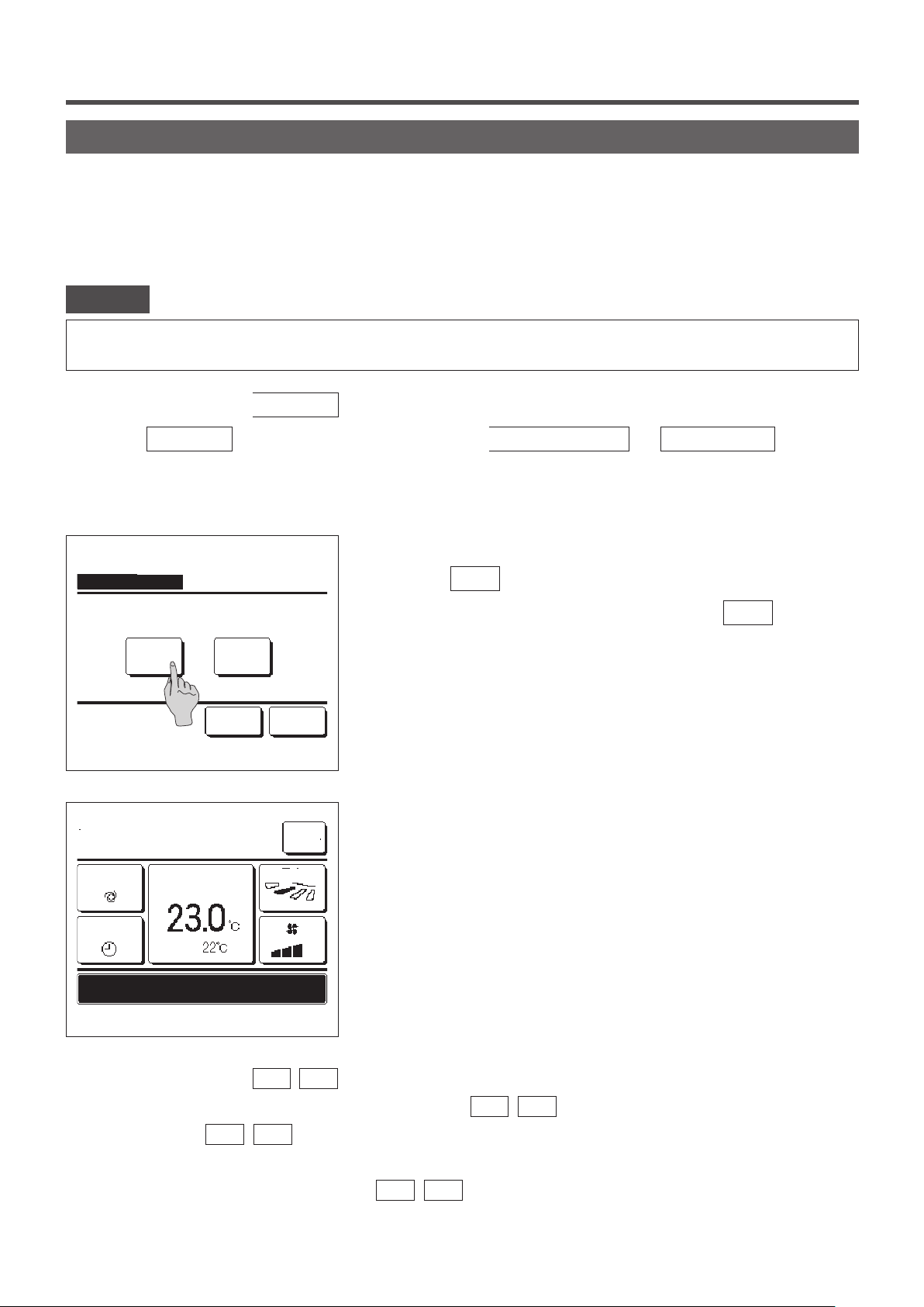
Home leave mode [Administrator password]
Use this function to maintain the room temperature at a moderate level for avoiding extremely hot or cool after leaving
home.
■Cooling and heating operations are controlled according to the outdoor air temperature.
■The set temperature and fan speed can be set.
Advice
· The Clock setting (☞page 33) must be made when the home leave mode is used.
· The home leave mode can be controlled from the main R/C only.
[To start operation from the
Menu button]
1
Tap the
Menu
button on the TOP screen and select
The administrator password input screen is displayed.
Input the administrator password.
2
Home leave mode
Start End
Details
Select the item.
Back
3
MEETING1
16:00
(Mon)
Auto
Set temp
Menu
Direction
Useful functions ⇒ Home leave
.
Display the home leave mode (Start, End) screen.
Tap the
To stop the home leave mode operation, tap the
button to start the home leave mode operation.
Start
End
button.
When the unit is in Home leave mode, “In operation for home leave.”
will be displayed on the message display.
Timer
Room
In operation for home leave.
F1: Silent mode cont. F2: Home leave mode
[To start operation from the F1
, F2 switches]
Use the F1/F2 function setting to change the function of the
When you press the
F1
(
) switch, the administrator password input screen is displayed.
F2
After you enter the password, the home leave mode will start.
To terminate the home leave mode, press the
F1
(
) button again.
F2
- 46 -
F1
(
) switch to Home leave mode.
F2
Page 49
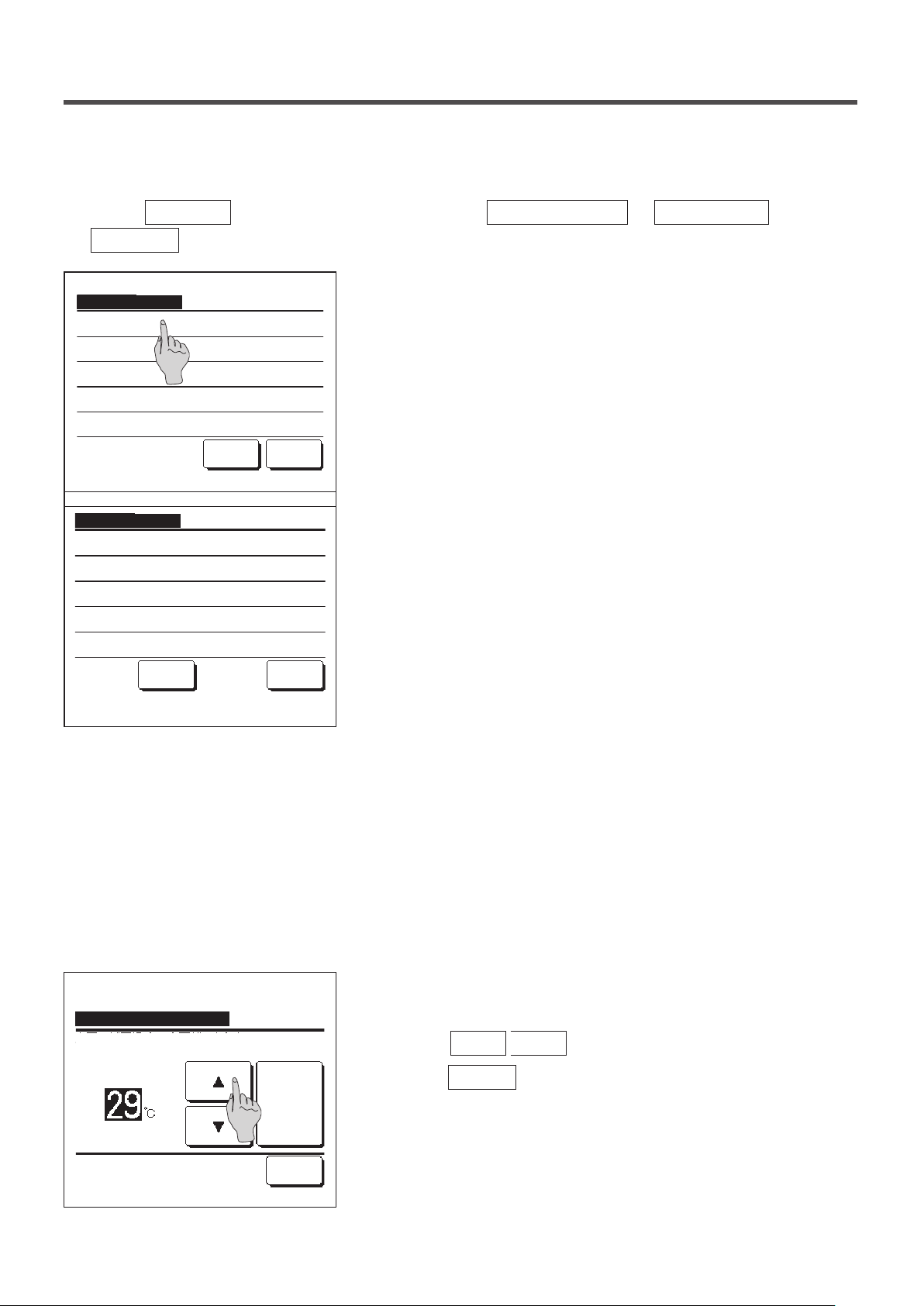
[To change the operation conditions]
Tap the Menu button on the TOP screen and select Useful functions ⇒ Home leave ⇒
1
Details .
The Details setting menu is displayed. The following items can be
2
Home leave mode
Determine temp rule in cooling
Determine temp rule in heating
Set temp rule in cooling
Set temp rule in heating
Fan speed rule in cooling
Next Back
Select the item.
set.
①
Determine temp rule in cooling: Set the outdoor temperature to
judge the operation mode in cooling.
Allowable setting range: 26°C to 35°C (at 3°C intervals)
Factory settings: 35°C (☞3)
Determine temp rule in heating: Set the outdoor temperature to
②
judge the operation mode in heating.
Home leave mode
Fan speed rule in heating
Previous Back
Select the item.
Allowable setting range: 0°C to 15°C (at 3°C intervals)
Factory settings: 0°C (☞4)
③ Set temp rule in cooling: Set the indoor temperature to start
operation in cooling.
Allowable setting range: 26°C to 33°C (at 1°C intervals)
Factory settings: 33°C (☞5)
Set temp rule in heating: Set the indoor temperature to start
④
operation in heating.
Allowable setting range: 10°C to 18°C (at 1°C intervals)
Factory settings: 10°C (☞6)
⑤ Fan speed rule in cooling: Set the fan speed in cooling mode.
Factory settings: Low (☞7)
⑥ Fan speed rule in heating: Set the fan speed in heating mode.
Factory settings: Low (☞8)
■Items set at the details setting menu are effective for the operation at the next
home leave mode.
Determine temp rule in cooling
Tap ▲▼ to set offset value.
Set
Back
Set the outdoor temperature for the “Determine temp rule in cooling”.
3
Select a desired setting temperature (26°C to 35°C, at 3°C intervals).
with the
Tap the
▲
Set
▼
buttons.
button after the setting.
- 47 -
Page 50
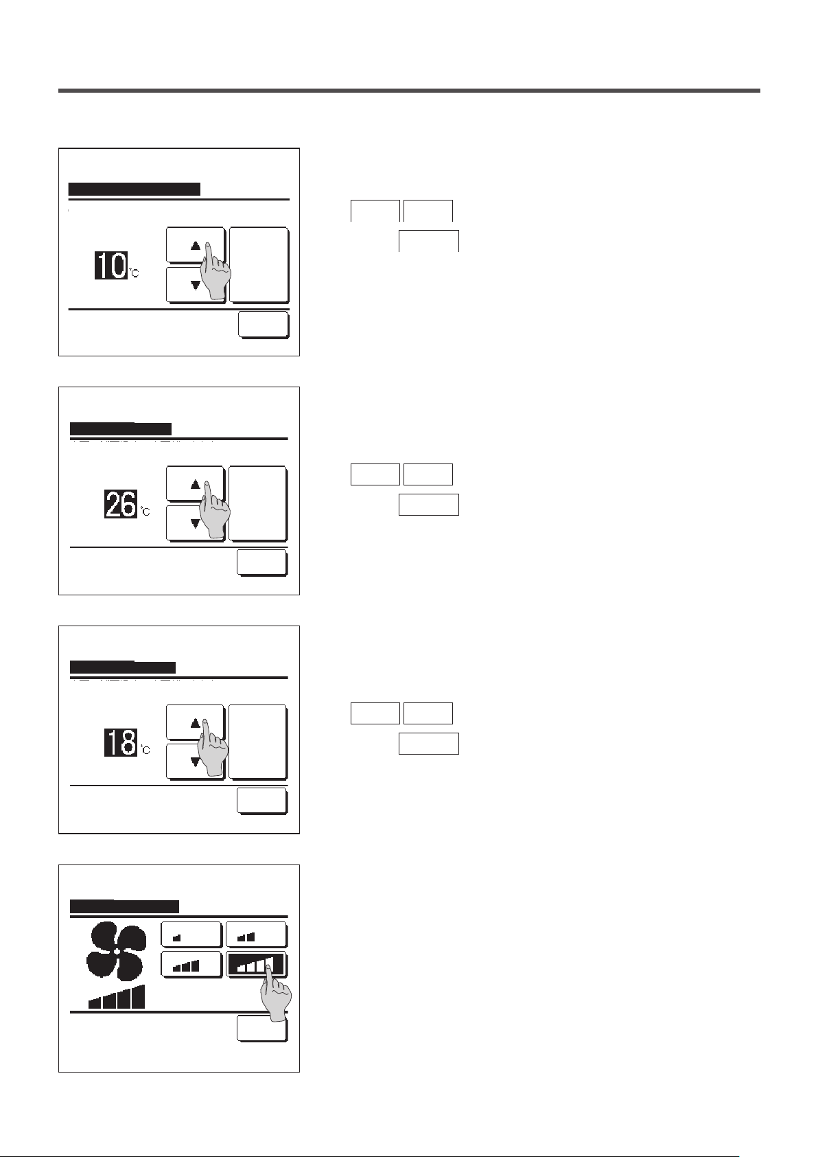
Set the outdoor temperature for the “Determine temp rule in heating”.
4
Determine temp rule in heating
Tap ▲▼ to set offset value.
Set temp rule in cooling
Tap ▲▼ to set offset value.
Set
Back
Set
Back
Select a desired set temp (0°C to 15°C, at 5°C intervals) with the
▲
Tap the
Set the indoor temperature to start operation in cooling after setting
5
▼
Set
buttons.
button after the setting.
the “Determine temp rule in cooling”.
Select a desired set temp (26°C to 33°C, at 1°C intervals) with the
▲
Tap the
▼
Set
buttons.
button after the setting.
Set temp rule in heating
Tap ▲▼ to set offset value.
Fan speed rule in cooling
Select the fan speed.
Set
Back
Back
Set the indoor temperature to start operation in heating after setting
6
the “Determine temp rule in heating”.
Select a desired set temp (10°C to 18°C, at 1°C intervals) with the
▲
Tap the
Set the fan speed in cooling mode.
7
▼
Set
buttons.
button after the setting.
Tap a desired fan speed.
- 48 -
Page 51
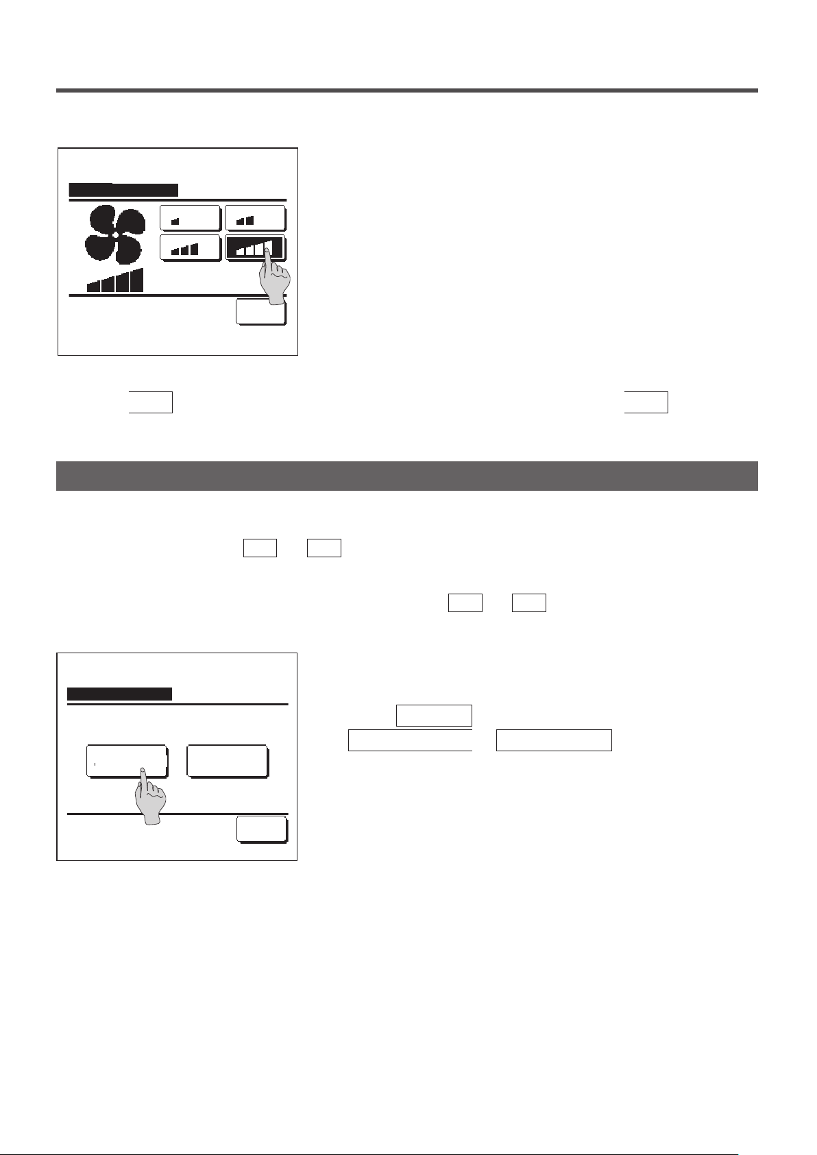
Set the fan speed in heating mode.
8
Fan speed rule in heating
Back
Select the fan speed.
After the settings of steps 3 to 8, the display returns to the Details setting menu 1.
9
Tap the
button to return to the home leave mode screen. To start operation, tap the
Back
Tap a desired fan speed.
Start
button.
Registering favorite settings
Operation mode, set temp, fan speed, fan direction can be registered as Favorite set 1 and Favorite set 2.
Allocating these settings to the
settings with a single tap of the button (☞page 63).
F1
and
switches allows you to perform operations with these registered
F2
Refer to the F1/F2 function setting (☞page 63) on how to set the
On the TOP screen, set the desired operation mode, set temp, fan
1
Favorite setting
Saving current state of operation
Saving where?
speed, and ap direction.
Tap the
Menu
Useful functions ⇒ Favorite setting
Favorite set 2Favorite set 1
The administrator password input screen is displayed.
Enter the administrator password.
Back
■ You cannot register the favorite settings during high power and energy-saving
operations.
The save location selection screen for favorite settings is displayed.
2
Select the save location.
If there is any data that was previously saved, that data will be
overwritten.
F1
and
F2
switches.
button on the TOP screen and select
.
- 49 -
Page 52
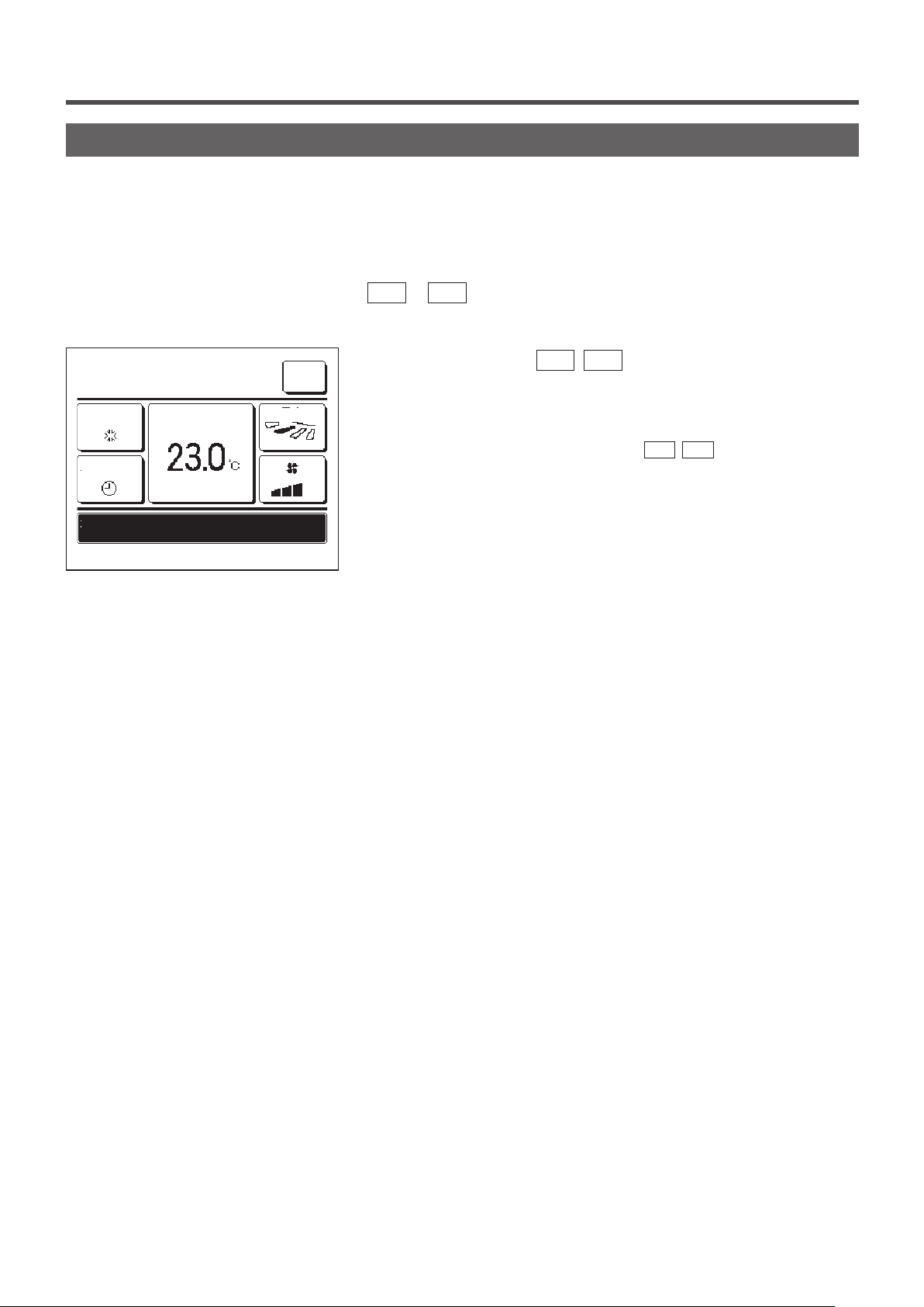
Favorite setting operation
You can start an operation with the operation mode, set temp, fan speed, flap direction registered to Favorite set 1
and Favorite set 2.
Settings for the operation mode, set temp, fan speed, flap direction can be registered from Favorite setting on the
menu (☞page 49).
Favorite setting operation must be set to the F1
1
16:32
(Mon)
Cooling
Timer
In operation for running.
F1: Favorite set 1 F2: Favorite set 2
Set temp
Menu
Direction
or F2 switch (☞page 63).
When you press the
temp, fan speed,
flap direction
F1
(F2
) switch, the operation mode, set
registered to Favorite set 1 or
Favorite set 2 will be enabled.
■ Operation will start even if you press the F1 (
stopped.
■You can change the operation mode, set temp, fan speed, flap direction after
the operation has started with the favorite setting operation.
■Following power on, the unit starts to operate initially with the following settings
for both Favorite set 1 and Favorite set 2.
Operation mode ...Cooling
Set temp ...28
Fan speed ...3-speed
Flap direction ...Position 2 (☞page 10)
*When an FDK with a left/right flap is connected
Left/right flap direction ...Center
°C
F2
) switch while the unit is
3D AUTO ...Disabled
■When Change set temp, Change operation mode, Change flap direction,
Change fan speed are restricted by the Permission/Prohibition setting (☞page
52), restricted items will not be reflected to the Favorite setting operation.
- 50 -
Page 53
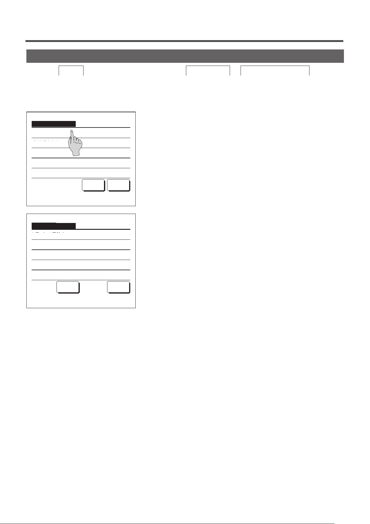
Administrator settings [Administrator password]
1
Tap the
Menu
button on the TOP screen and select
The administrator password input screen is displayed.
Enter the administrator password.
2
Administrator settings
Permission/Prohibition setting
Outdoor unit silent mode timer
Setting temp range
Temp increment setting
Set temp display
Next Back
Select the item.
Administrator settings
R/C display setting
Change administrator password
F1/F2 function setting
User setting ⇒ Administrator settings
.
When the administrator setting menu is displayed, tap a desired
item.
■ Permission/Prohibition setting …☞page52
■ Outdoor unit silent mode timer …☞page53
■ Setting temp range …☞page54
■ Temp increment setting …☞page56
■ Set temp display …☞page56
■ R/C display setting …☞page57
■ Change administrator password …☞page62
■ F1/F2 function setting …☞page63
Select the item.
Previous Back
- 51 -
Page 54
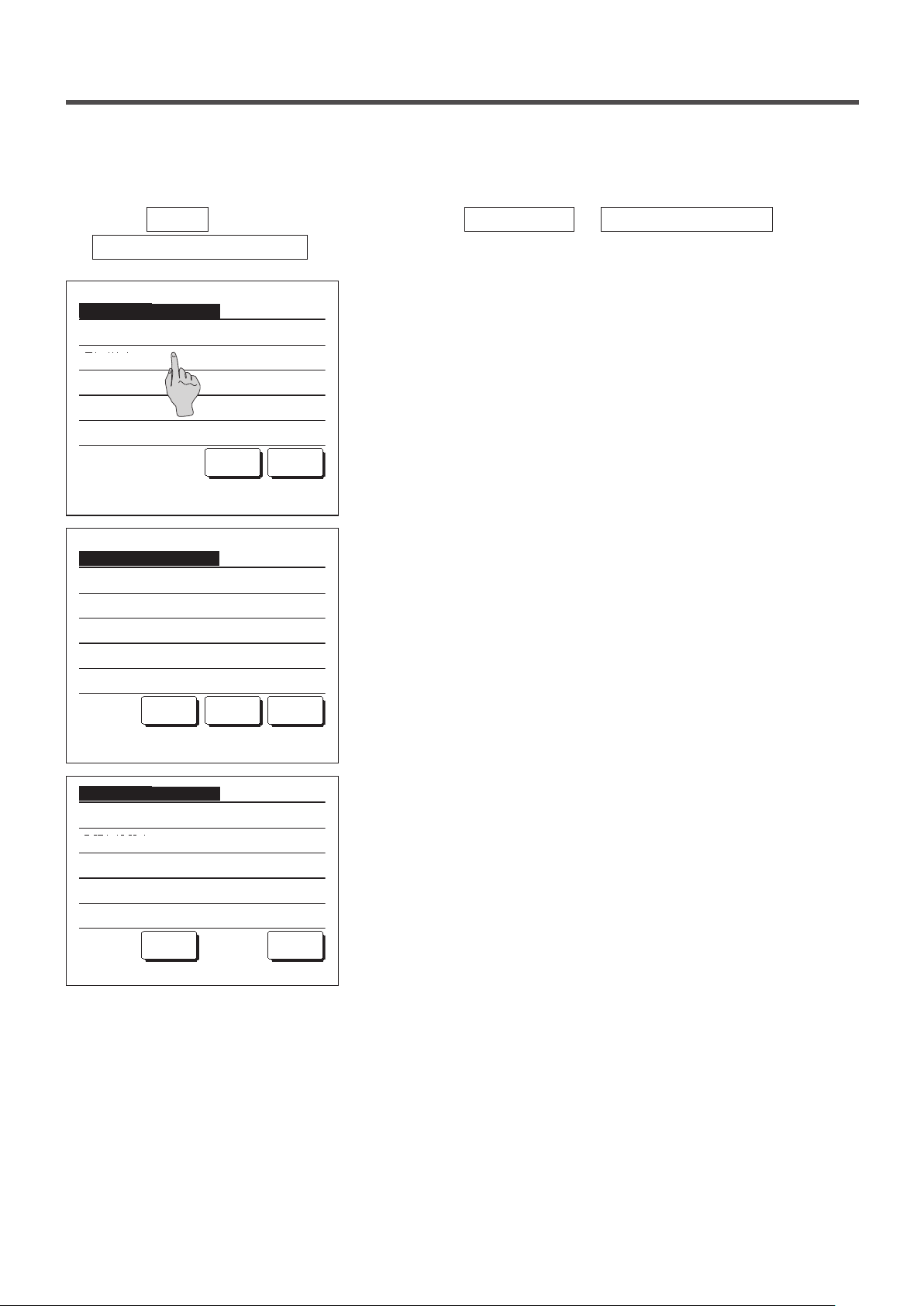
■Permission/Prohibition setting
1
Tap the
Menu
Permission/Prohibition setting
Permission/Prohibition setting
Bat.set.
Run/Stop
Change set temp
Change operation mode
Change flap direction
Select the item.
Permission/Prohibition setting
Individual flap control
Change the fan speed
High power operation
Energy-saving operation
Timer
Previous
Select the item.
Permission/Prohibition setting
Weekly timer
Select the language
Anti draft setting
button on the TOP screen and select
. The Permission/Prohibition setting menu is displayed.
Following items can be selected, and the Permission or Prohibition
2
can be set for them.
If the Permission is set, the operation is accepted.
If the Prohibition is set, the message “Invalid request” is displayed
for 3 seconds.
Some items may require the administrator password.
Next Back
■Operation with Prohibition setting
Bat.set .... Can set to permit/prohibit all items from ② to ⑬ at
①
Run/Stop … Run/Stop operation is prohibited.
②
Change set temp … Change set temp operation is prohibited.
③
Change operation mode … Change operation mode operation is prohibited.
④
Change ap direction … Change ap direction operation is prohibited.
⑤
Individual ap control … Administrator password is required for this control.
⑥
Change the fan speed … Change fan speed operation is prohibited.
⑦
Next Back
High power operation … High power operation is prohibited.
⑧
Energy-saving operation … Energy-saving operation is prohibited.
⑨
Timer … Timer setting operation is prohibited.
⑩
Weekly timer … Administrator password is required for these settings.
⑪
Select the language … Administrator password is required for this selection.
⑫
Anti draft setting ... Administrator password is required when setting anti
⑬
User setting ⇒ Administrator settings
once.
draft.
⇒
Select the item.
Previous
Back
- 52 -
Page 55
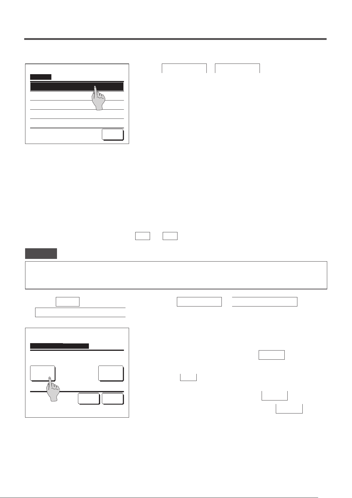
Run/Stop
Permission
Prohibition
3
Tap
Permission
or
Prohibition
for each item.
Select the item.
Back
■Outdoor unit silent mode timer
Set the period of time to operate the OU with prioritizing the quietness.
When the Outdoor unit silent mode timer setting is Enabled, the silent mode operation starts and ends everyday at
the same time until the setting is Disable.
Silent mode operation can be started from an R/C operation without using the timer.
Use Silent mode cont. (☞page 63) for the
Advice
· When the Outdoor unit silent mode timer is used, the Clock setting (☞page 33) must be made.
· The Outdoor unit silent mode timer can be set from the main R/C only.
· The air-conditioner cannot be operated at the maximum capacity during the silent mode operation.
1
Tap the
Menu
Outdoor unit silent mode timer
button on the TOP screen and select
.
F1
and
switches.
F2
User setting ⇒ Administrator settings
⇒
Outdoor unit silent mode timer
Start time
State
Disable
Select the item.
0:00 AM
End time
1:00 AM
Change
Set Back
The Outdoor unit silent mode timer setting screen is displayed.
2
If it is OK that the Silent mode operation is performed at the start and
end time displayed on the screen, tap the
State
button to select
“State Enable”.
When the
■
mode timer is not controlled.
After changing to a desired setting, tap the
To change the start time or the end time, tap the
button indicates “State Disable”, the Outdoor unit silent
State
Set
Change
button.
button.
- 53 -
Page 56
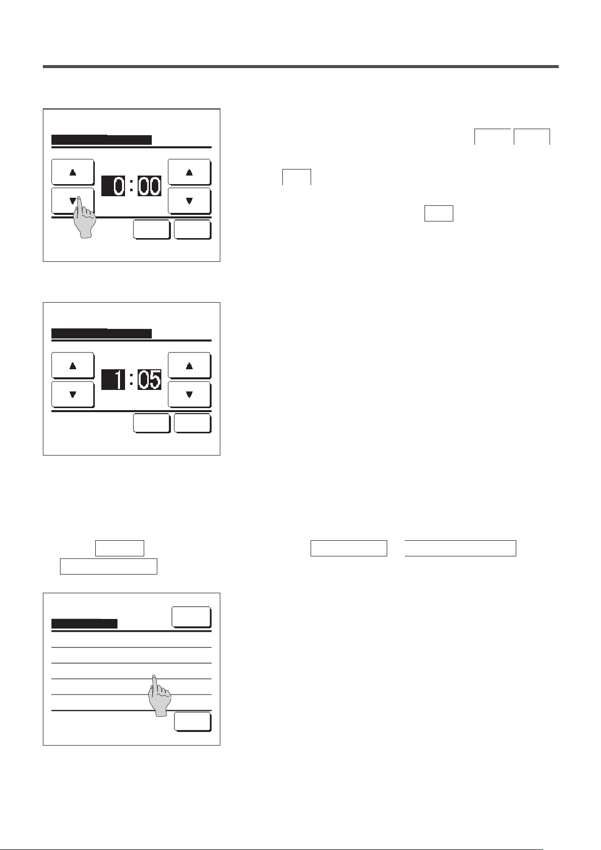
Outdoor unit silent mode timer
Start time
AM
Set Back
Tap ▲▼ to set clock time & tap [Set].
Outdoor unit silent mode timer
End time
AM
Set the start time for the
3
Outdoor unit s
Select a desired time (at 5-min intervals) with the
ilent mode timer.
▲
buttons.
If the
button is tapped after setting the start time, the display
Set
changes to the end time setting screen. Set a desired time (at 5-min
intervals) for the end time and tap the
Set
button.
▼
Set Back
Tap ▲▼ to set clock time & tap [Set].
■Setting temp range
Limited range of setting temperature in the heating or the cooling operation can be selected.
1
Tap the
Menu
Setting temp range
Setting temp range
Setting upper/lower limit temp in cooling
Setting upper/lower limit temp in heating
Temp range setting Enable/Disable
button on the TOP screen and select
.
Setting temp range menu screen is displayed.
2
Menu
① Setting upper/lower limit temp in cooling (☞2)
... Set the range of setting temperature in the cooling operation.
(Including the Dry and Auto operations)
② Setting upper/lower limit temp in heating (☞3)
... Set the range of setting temperature in the heating operation.
User setting ⇒ Administrator settings
⇒
Select the item.
Back
③ Temp range setting Enable/Disable (☞4)
... Set whether the limit on the setting temperature range is
enabled or disabled.
- 54 -
Page 57
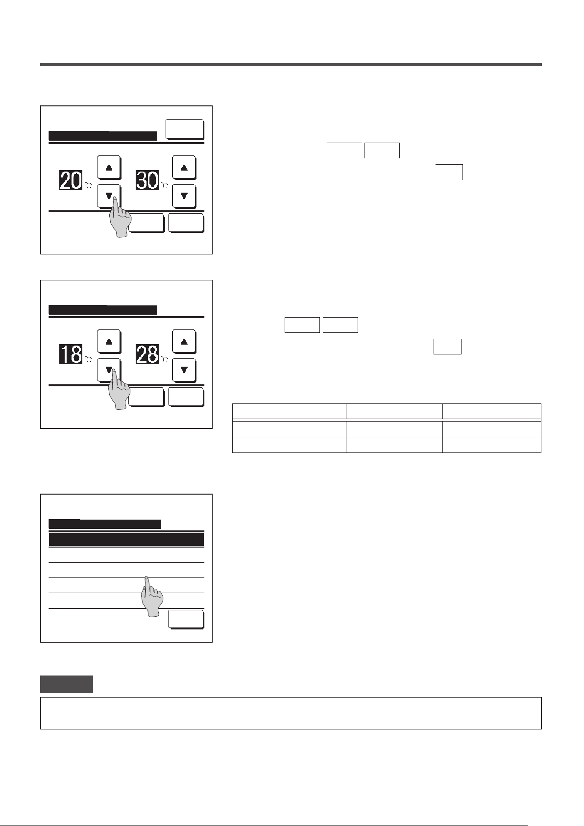
Setting upper/lower limit temp in cooling
Cool/Dry/Fan
lower limit
upper limit
Menu
Set the range of setting temperature in the cooling operation.
3
Select at desired lower and upper limit temperatures (at 1°C
intervals) with the
After Selecting the desired settings, tap the
▲
▼
buttons.
Set
button.
Set
Tap
to set temp & tap [Set].
▲▼
Setting upper/lower limit temp in heating
Heating
lower limit
Tap
to set temp & tap [Set].
▲▼
Temp range setting Enable/Disable
Disable
Enable
Enable : No reflect on display
upper limit
Set
Back
Back
Set the range of setting temperature in the heating operation.
4
Select desired lower and upper limit temperatures (at 1°C intervals)
with the
After selecting the desired settings, tap the
■Setting temperatures can be set in the following ranges.
▲
▼
buttons.
Set
button.
Lower limit value Upper limit value
Cooling/Dry/Auto 16 to 28°C 30 to 35°C
Heating 10 to 22°C 22 to 30°C
Select the control contents of restriction on the setting temperature
5
range.
①
Disable
Restriction on the setting temperature range is disabled.
...
②
Enable
The operation is restricted within the set temperature range.
...
③
Enable: No reflect on display
... The set temperature on the R/C can be displayed beyond the
Select the item.
Back
set temperature range but actual operation is restricted within
the set temperature range.
Advice
· Over-cooling during the cooling operation or over-heating during the heating operation is not economical.
·
It is recommended to set the temperature range a little higher in the cooling operation or a little lower in the heating operation.
- 55 -
Page 58

■Temp increment setting
Temperature increment for the change of the set temp can be changed.
Tap the
1
Temp increment setting
Temp increment setting
Menu
button on the TOP screen and select
.
The Temp increment setting screen is displayed.
2
Tap a desired temperature increment.
① 1.0°C........ Setting temperature can be set at 1.0°C intervals.
② 0.5°C........ Setting temperature can be set at 0.5°C intervals.
Select the item.
Back
■Set temp display
Set temp displayed on the TOP screen can be changed.
Tap the
1
Set temp display
Menu
button on the TOP screen and select
.
User setting ⇒ Administrator settings
(ex. …⇔ 24.0°C ⇔ 25.0°C ⇔ 26.0°C ⇔…)
(ex. …⇔ 24.0°C ⇔ 24.5°C ⇔ 25.0°C ⇔…)
User setting ⇒ Administrator settings
⇒
⇒
Set temp display
Display set temp
Display temp difference from base temp
Select the item.
Base temp setting
Set the base temp
Back
Set
The Set temp display menu is displayed.
2
Display set temp
①
... Set temp is displayed.
Display temp difference from base temp
②
... The difference from the base temperature is displayed. When
you select the Display temp difference from base temp, the
Base temp setting screen is displayed (☞2).
Set the base temperature.
3
Tap
to set temp & tap [Set].
▲▼
Back
- 56 -
Page 59

■R/C display setting
Contents of display on the R/C can be changed.
Tap the
1
Menu
R/C display setting
R/C display setting
Room name
Name of IU
Indoor temp display
Error code display
Heating standby display
Select the item.
R/C display setting
Defrost operation display
Auto cooling/heating display
Display temp of R/C, Room, Outdoor
button on the TOP screen and select
.
The R/C display setting menu screen is displayed.
2
Room name …
①
Name of I/U …
②
Indoor temp display …
③
Error code display …
④
Heating standby display …
Next Back
⑤
Defrost operation display …
⑥
Auto cooling/heating display …
⑦
Display temp of R/C, Room, Outdoor …
⑧
User setting ⇒ Administrator settings
page
58
58
59
60
60
61
61
62
☞page
☞page
☞page
☞
☞page
☞page
☞page
☞page
⇒
Select the item.
Previous Back
- 57 -
Page 60

① Room name
Set the room name to be displayed on the TOP screen.
Tap the
1
R/C display setting
Room name
カナ
Input the name & tap [Set].
MEETING1
14:00 (Tue)
Auto
Menu
AlphabetNumber
漢字
Set temp
button on the TOP screen and select
⇒
Room name
Set
.
The Room name input screen is displayed.
2
The room name can be set with up to 9 2-byte letters (18 1-byte
letters).
汉字
You can enter alphanumeric, Japanese Kana, Kanji, Cyrillic, or
Chinese characters.
Tap the
NextDelete
Back
group.
Previous
When you have nished inputting the room name, tap
The room name is displayed on the TOP screen.
CENTER
Menu
Direction
User setting ⇒ Administrator settings ⇒
or
Next
button to display next character
.
Set
Timer
In operation for running.
F1: High power F2: Energy-saving
② Name of IU
Set the name of IU to be added to the IU address button.
Tap the
1
R/C display setting
IU select
Menu
button on the TOP screen and select
⇒
Name of IU
.
The IU select screen is displayed.
2
When two or more IUs are connected to the R/C, a list of IUs is
displayed. Tap the button for the IU (address number) to set the
name.
User setting ⇒ Administrator settings ⇒
Select an IU address.
Next Back
- 58 -
Page 61

Name of IU
Set
When the letter selection screen is displayed same as at the setting
3
of the name of R/C (☞ 58), enter letters.
AlphabetNumber
カナ
Input the name & tap [Set].
漢字
NextDelete
汉字
Back
③ Indoor temp. display
Select ON/OFF for the room temperature display.
Tap the
1
R/C display setting
Menu
button on the TOP screen and select
⇒
Indoor temp display
2
Indoor temp display
OFF
ON
The name of IU can be entered up to 4 2-byte (8 1-byte) letters.
When the input is over, tap the
button. The text “The
Set
registration is completed.” is displayed, and the settings are
completed.
User setting ⇒ Administrator settings ⇒
.
The Indoor temp display screen is displayed.
On the Indoor temp display screen, select ON/OFF of the display.
When R/C sensor setting is enabled, the room temperature (R/C) is
displayed (refer to the installation manual on how to make these
Select the item.
MEETING1
16:00
(Mon)
Auto
Timer
Now stopping.
F1: High power F2: Energy-saving
Set temp
Room
Back
Menu
Direction
settings).
OFF … Room temperature is not displayed on the TOP screen.
ON … Room temperature is displayed on the TOP screen.
When R/C sensor setting is disabled, the room temperature ○°C is
displayed.
- 59 -
Page 62

MEETING1
16:00
(Mon)
Auto
Timer
In operation for running.
F1: High power F2: Energy-saving
Set temp
Room(R/C)
Menu
Direction
④ Error code display
Select ON/OFF for the Error code display.
Tap the
1
R/C display setting
Error code display
ON
OFF
Menu
button on the TOP screen and select
⇒
Error code display
When R/C sensor setting is enabled, the room temperature (R/C)
°C is displayed (refer to the installation manual on how to make
these settings).
User setting ⇒ Administrator settings ⇒
.
The Error code display screen is displayed.
2
On the Error code display selection screen, select ON/OFF of the
display.
ON ... When there is any error on the unit, the message
○
Select the item.
Back
⑤ Heating standby display
Select ON/OFF for the Heating standby display.
Tap the
1
R/C display setting
Menu
button on the TOP screen and select
⇒
Heating standby display
2
Heating standby display
ON
OFF
“Prot.stp.ON E○ Touch here for contact. History can be
checked from Menu.” is displayed on the TOP screen
message display.
OFF ... The message is not displayed even if there is any error.
User setting ⇒ Administrator settings ⇒
.
The Heating standby display selection screen is displayed.
On the Heating standby display selection screen, select ON/OFF of
the display.
The heating standby control is operated to prevent blowing of cold
air at the start of heating operation.
Select the item.
Back
ON … The message “Heating standby” is displayed during the
heating standby control.
OFF … The message “Heating standby” is not displayed.
- 60 -
Page 63

⑥ Defrost operation display
When frost on the OU heat exchanger is accumulated and the conditions for start defrosting are established, the
defrost operation control is performed automatically. Select ON/OFF for the Defrost operation display.
Tap the
1
R/C display setting
Defrost operation display
ON
OFF
Menu
button on the TOP screen and select
⇒
Defrost operation display
The Defrost operation display selection screen is displayed.
2
On the Defrost operation display selection screen, select ON/OFF of
the display. The heating standby control is operated to prevent
blowing of cold air at the start of a heating operation.
ON … The message “Defrost operation” is displayed during the
defrost operation.
Select the item.
Back
OFF … The message “Defrost operation” is not displayed.
⑦ Auto cooling/heating display
Select ON/OFF for the display of the Auto cooling or heating.
Tap the
1
R/C display setting
Menu
button on the TOP screen and select
⇒
Auto cooling/heating display
User setting ⇒ Administrator settings ⇒
.
User setting ⇒ Administrator settings ⇒
.
Auto cooling/heating display
ON
OFF
Select the item.
Back
The Auto cooling/heating display selection screen is displayed.
2
On the Auto cooling/heating display selection screen, select ON/OFF
of the display.
ON … The message “Auto Cooling” or “Auto Heating” is displayed
on the “Change operation mode” button at the TOP screen
during the auto mode operation.
OFF … The message “Auto” is displayed on the “Change operation
mode” button at the TOP screen.
- 61 -
Page 64
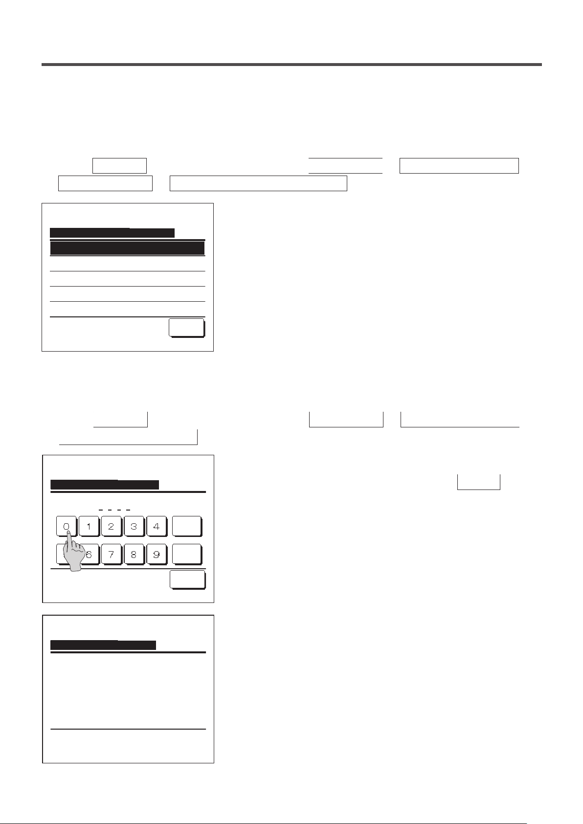
⑧ Display temp of R/C, Room, Outdoor
Select ON/OFF for the display of the R/C sensor temperature, room temperature and outdoor temperature.
1
Tap the
Menu
R/C display setting
Display temp of R/C, Room, Outdoor
ON
OFF
button on the TOP screen and select
⇒
Display temp of R/C, Room, Outdoor
The Display temp of R/C, Room, Outdoor selection screen is
2
displayed.
On the Display temp of R/C, Room, Outdoor selection screen, select
ON/OFF of the display.
ON … Each temperature is displayed on the TOP screen.
OFF … These temperatures are not displayed on the TOP screen.
Select the item.
Back
■Change administrator password
Administrator password can be changed.
1
Tap the
Menu
Change administrator password
button on the TOP screen and select
.
User setting ⇒ Administrator settings ⇒
.
User setting ⇒ Administrator settings ⇒
Change administrator password
Input 4 digit number & tap [Set]
Change administrator password
Password has been changed.
Delete
Set
Back
The Change administrator password screen is displayed.
2
Enter the password (4-digit number) and tap the
The password change conrmation screen is displayed for 3
3
Set
seconds, and the display returns to the administrator settings menu
screen.
button.
- 62 -
Page 65
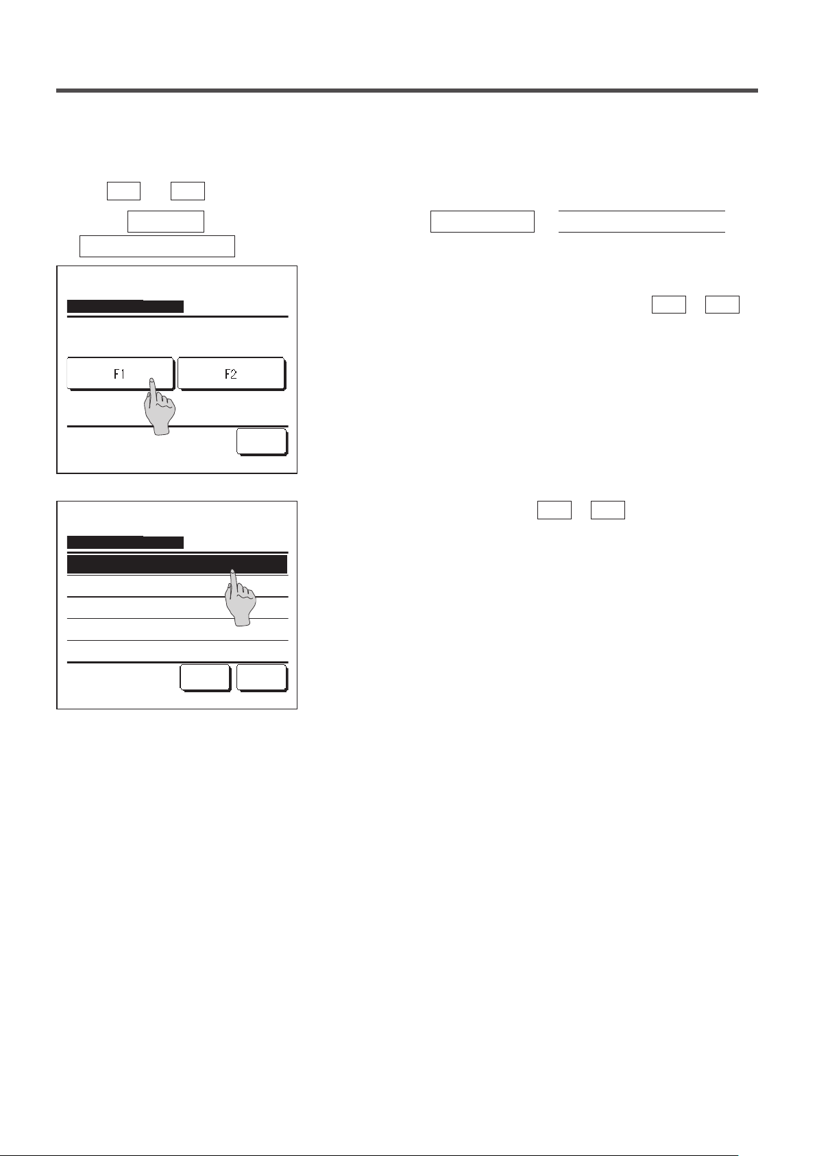
■F1/F2 function setting
Use the
Tap the
1
F1
and
Menu
switches to change the functions to operate.
F2
button on the TOP screen and select
F1/F2 function setting .
F1/F2 function setting
Select the function of F1/F2
F1: High power F2: Energy-saving
F1/F2 function setting
High power operation
Energy-saving operation
Silent mode cont.
Home leave mode
Favorite set 1
Next
Back
Back
User setting ⇒ Administrator settings ⇒
The F1/F2 function setting screen is displayed.
2
On the F1/F2 function setting screen, tap the side (
switch) you desire to change.
The currently set functions are displayed below the buttons.
Select the function to set to the
3
F1
or
F2
switch.
The following functions can be selected.
High power operation …☞page 14
・
Energy-saving operation …☞page 15
・
Silent mode control …☞page 64
・
Home leave mode …☞page 46
・
Favorite setting operation …☞page 50
・
F1
or
F2
Filter sign reset …☞page 65
・
- 63 -
Page 66
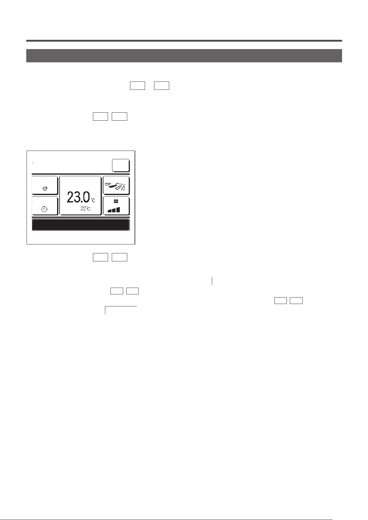
Silent mode control
The OU is controlled with priority on quietness. You can start/stop the silent mode control with a single tap of a button.
Silent mode control must be set to the
F1
or
switch (☞page 63). Use the Outdoor unit silent mode timer
F2
to set the start and end time (☞page 53).
When you press the
1
F1 (F2
) switch, the administrator password input screen is displayed.
After you enter the password, the silent mode control will start.
During silent mode control, “Outdoor unit silent mode control ON”
2
MEETING1
16:00
(Mon)
Auto
Timer
Outdoor unit silent mode control ON
F1: Silent mode cont F2: Home leave mode
When you press the
3
Set temp
Room
F1 (F2
Menu
Direction
will be displayed on the message display.
) switch during silent mode control, the display changes to the administrator
password input screen. After you enter the password, the silent mode control will terminate.
■Silent mode control will not be disabled even if you press the
Terminate the control with the
■This operation is to select enable/disable of silent mode control. You cannot start the operation with the
Start the operation with the
■When the sub R/C is set, the silent mode control cannot be used.
■During silent mode control, operation with maximum capacity is not allowed.
F1 (F2
Run/Stop
) switch.
switch.
Run/Stop
switch.
F1 (F2
) switches.
- 64 -
Page 67
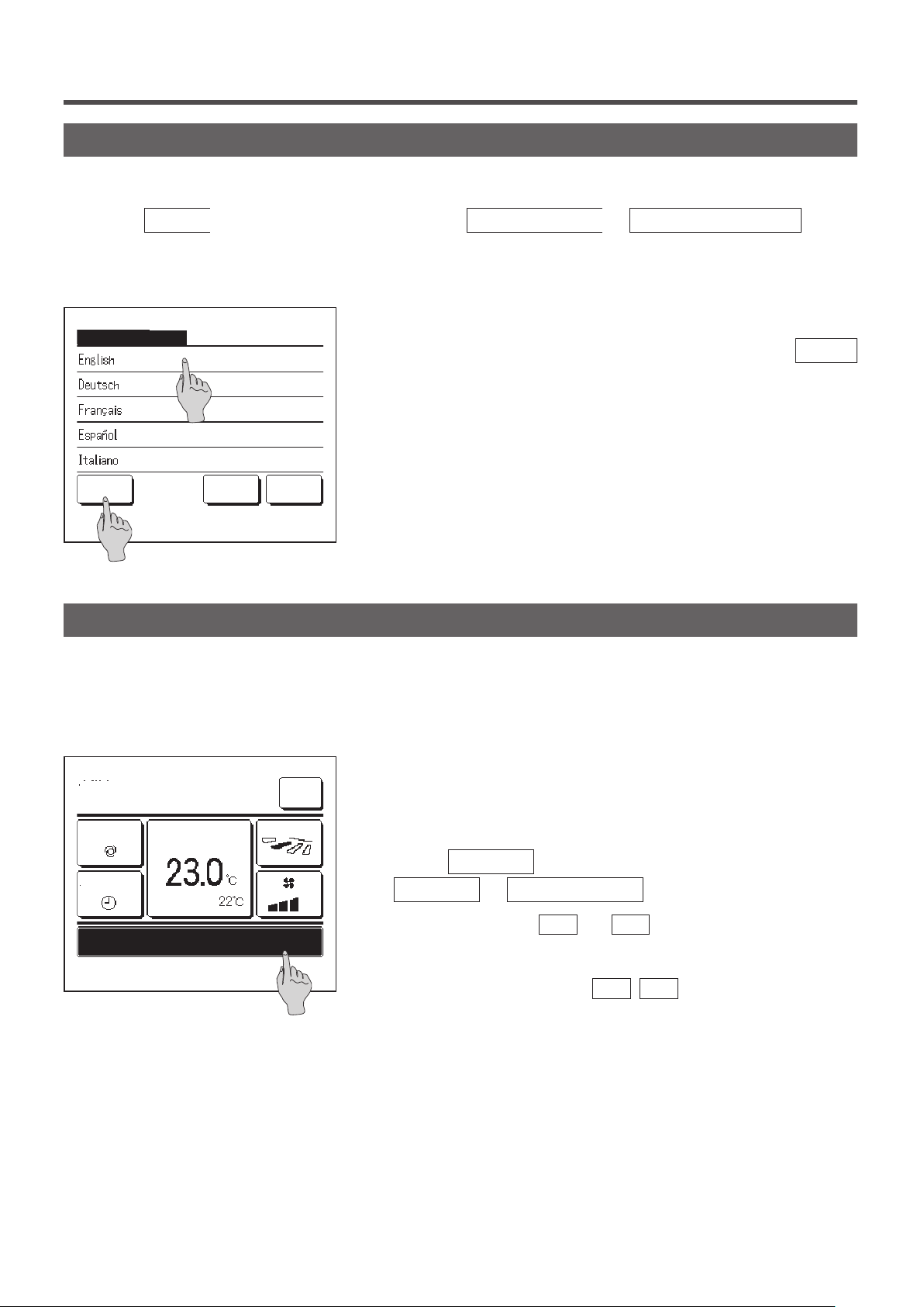
Select the language
Select the language to be displayed on the R/C.
Tap the
1
■Depending on how the Permission/Prohibition setting (☞page 52) is set, the administrator password input screen may be
displayed.
Select the language
Menu
button on the TOP screen and select
The menu for select the language is displayed.
2
Select the language to be displayed on the R/C and tap the
Useful functions ⇒ Select the language
.
Set
button.
You can select from the following languages:
English/German/French/Spanish/Italian/
Set
Select the language
Next
Back
Dutch/Turkish/Portugal/Russian/
Polish/Japanese/Chinese
Filter sign reset
In order to announce the time for cleaning of the air lter, the message of “Filter cleaning. Touch here.” is displayed
when the cumulative operation time of the IU reaches the preset time. After you clean the lter, you must reset the
operation time.
Tap the message display on the TOP screen.
1
MEETING1
16:00
(Mon)
Set temp
Timer
Room(R/C)
Filter cleaning. Touch here.
F1: High power F2: Energy-saving
Menu
Direction
You can also perform lter sign reset from the menu before the
message “Filter cleaning. Touch here.” is displayed.
Tap the
Menu
Filter ⇒ Filter sign reset
You can also use the
button on the TOP screen and select
.
F1
and
switches to perform this
F2
operation.
Set the lter sign reset to the
F1
(
) switch using the Switch
F2
function (☞page 63) to perform this operation.
- 65 -
Page 68
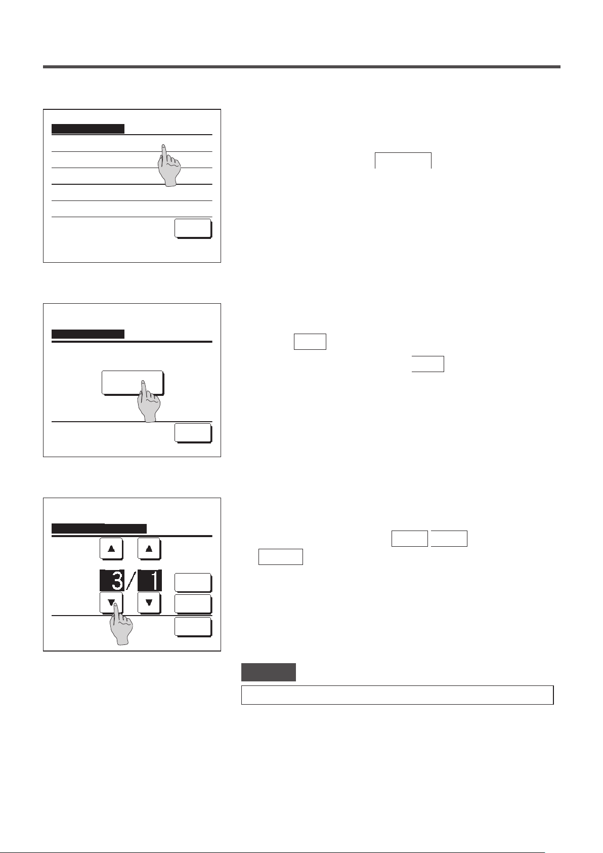
Filter sign reset
Reset
Setting next cleaning date
Select the item.
Back
The lter sign reset menu screen is displayed.
2
To reset the lter sign, tap
Reset
. (☞3)
To set next cleaning date, tap Setting next cleaning date. (☞4)
Acknowledge screen for the Filter sign reset screen is displayed.
3
Filter sign reset
Do you want to reset the filter sign?
Yes
Select the item.
Setting next cleaning date
dd mm
Set the date.
Back
Cancel
Set
Back
Tap the
If you do not want to reset, tap the
The Setting next cleaning date screen is displayed.
4
Select a desired date with the
Set
Yes
button.
button.
▲
Back
button.
buttons and tap the
▼
The message of “Filter cleaning. Touch here.” will be displayed on
the set date.
Advice
· When setting next cleaning date, the Clock setting must be made. (☞page 33)
- 66 -
Page 69
5. Maintenance of unit and LCD
Maintenance of unit and LCD
■Wipe the surface of LCD and main body of the remote control with a dry cloth when cleaning is required.
■If the dirt on the surface cannot be removed, soak the cloth in neutral detergent diluted with water, squeeze the cloth tightly, and clean the
surface. Wipe the surface with a dry cloth then.
Note
Do not use any paint thinner, organic solvent, or strong acid.
Warning
Do not use flammable materials (e.g. hairspray or insecticide) near
the unit.
Do not clean the unit with benzene or paint thinner.
It could cause crack damage to the unit, electric shocks, or fire.
- 67 -
Page 70
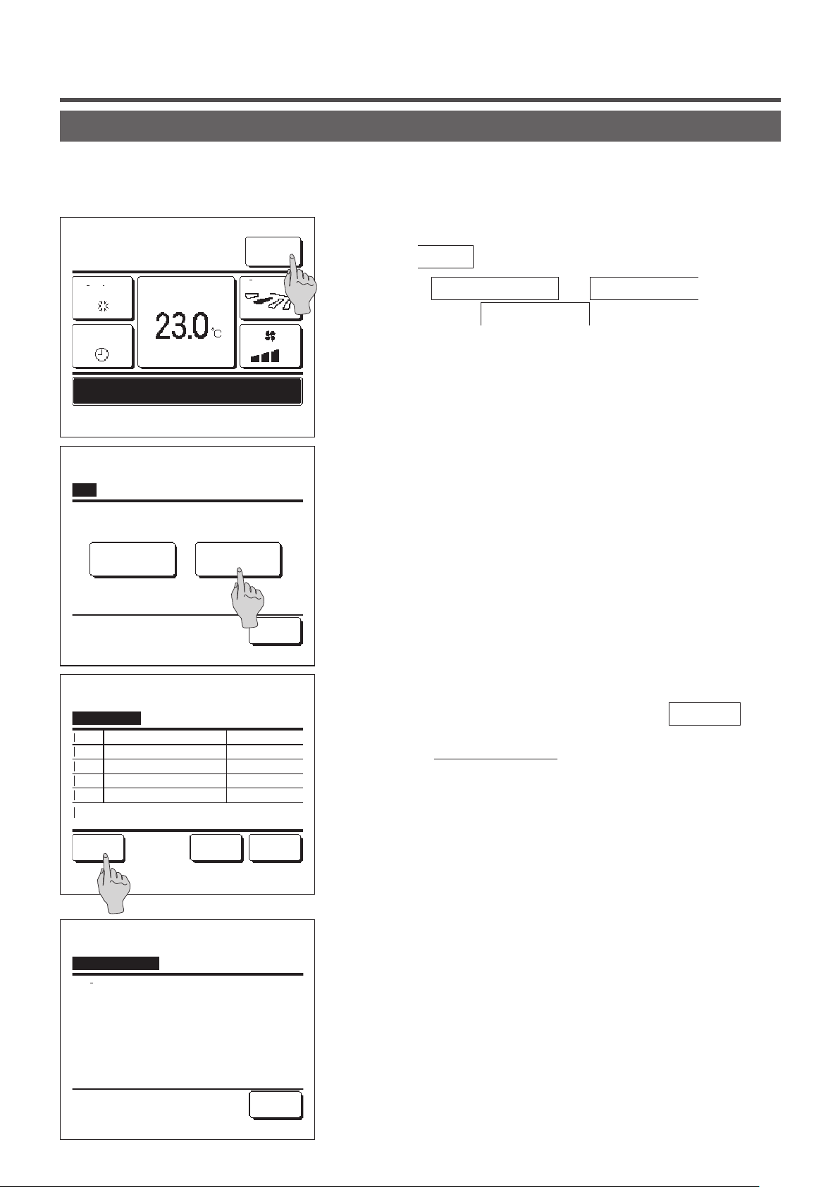
6. Useful information
Contact company & Error display
If any error occurs on the air conditioner, the “Unit protection stop” is indicated on the message display. Take the
following measures, stop the operation and consult your dealer.
The “Unit protection stop” is displayed on the message display.
1
6:57PM (Wed)
Menu
Tap the
Menu
button.
Cooling
Timer
Prot.stp.ON E09 Touch here for contact.
History can be checked from Menu.
F1: High power
Menu
Normal display Error display
Select the item.
Set temp
F2: Energy-saving
Direction
Back
When the
displayed, tap the
Contents of error are displayed.
2
Normal display
Error display
and
Error display
button.
button is
Error display
Code
IU
E07
000 IU000
E08
001 IU001
E09
002 IU002
E40
003 IU003
R/C : Normal
Select the item.
Contact company
Company
MHI
Phone No.
000-000-0000
OU
00
BackNextContact
Back
After checking the error contents (Code), tap the
Contact
button.
Or tap the
Normal display
button on the previous screen and
select the “Contact company” on the menu screen and tap it.
Company information (Name and phone No. of contact) is
3
displayed.
This is displayed when it has been preset by your dealer.
- 68 -
Page 71
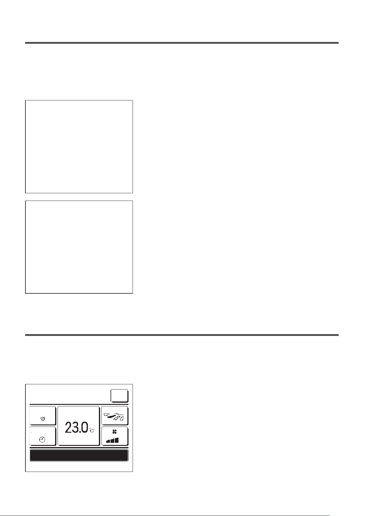
7. Notice of inspection date
If the next service date is set on the Service & Maintenance menu by your dealer, the following screen is displayed for
5 seconds at the start of operation and for 20 seconds from the end of operation on the beginning of the month which
includes the set date.
When this screen is displayed, contact your dealer.
Usage time 1 years & 9 months
Next check 10 / 2020
Company
Phone No.
When the period of use exceeds 10 years, the screen shown at left is
displayed.
Usage time 12 years & 9 months
Next check 10 / 2020
Company
Phone No.
It's the end of a product's life.
Please make an inspection
When this screen is displayed, contact your dealer.
8. Message display
During operation, the following messages will be displayed on the message display to notify the current condition of
the unit.
“
Standby. Wait a while.” displayed
■
The message “Standby. Wait a while.” may be displayed (maximum of
0:33 (Sat)
Menu
30 minutes) on the R/C during the rst operation following a breaker
Auto
Timer
Standby. Wait a while.
F1: High power F2: Energy-saving
Set temp
Direction
power on or power loss.
This does not indicate a failure; it is caused by the cooling machine oil
protect control that is activated in order to protect the compressor.
Please wait until the message “Standby. Wait a while.” disappears.
- 69 -
Page 72
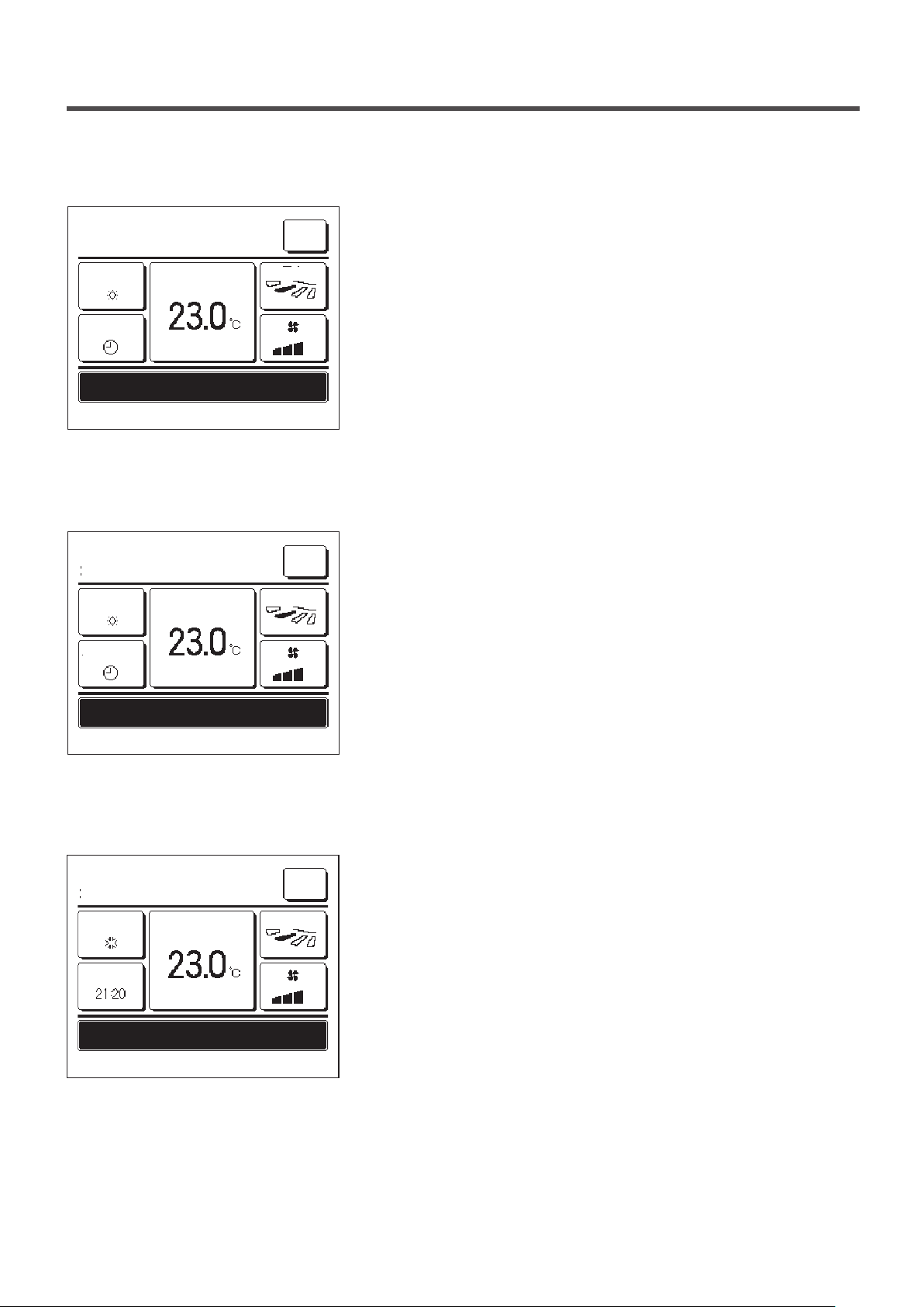
“
In operation for defrosting.” display
■
When frost forms on the OU, the heating performance will decrease.
20:20
(Tue)
Menu
This will cause the unit to automatically switch to defrost operation, and
Heating
Set temp
Direction
hot air will stop blowing out from the IO.
The message “In operation for defrosting.” will be displayed on the
Timer
message display. After the defrost operation has completed, “In
operation for defrosting.” will disappear, and the unit will switch back to
In operation for defrosting.
F1: High power F2: Energy-saving
“
In operation for heating standby.” displayed
■
its normal heating operation.
To prevent any cold air blowing out from the IO at the start of a heating
20:20
(Tue)
Heating
Set temp
Menu
Direction
operation, the unit stops the fan and displays “In operation for heating
standby.” on the message display.
When the unit is ready to blow out hot air, the message “In operation for
Timer
In operation for heating standby.
heating standby.” disappears, and the unit will start heating operation.
F1: High power F2: Energy-saving
“
In operation for warming up.” display
■
When you select to enable warming up by the Set ON timer by hour (
20:20
(Tue)
Cooling
Set temp
Menu
Direction
page 39) or Set ON timer by clock (☞page 41), the operation will
start 50 to 60 minutes earlier, which is predicted based on the previous
warm up operation, so that the room will be close to the set temp by the
ON
time it reaches the operation start time.
During the warm up operation, the message “In operation for warming
In operation for warming up.
F1: High power F2: Energy-saving
up.” will be displayed on the message display.
This message will disappear at the time set for operation start.
☞
- 70 -
Page 73
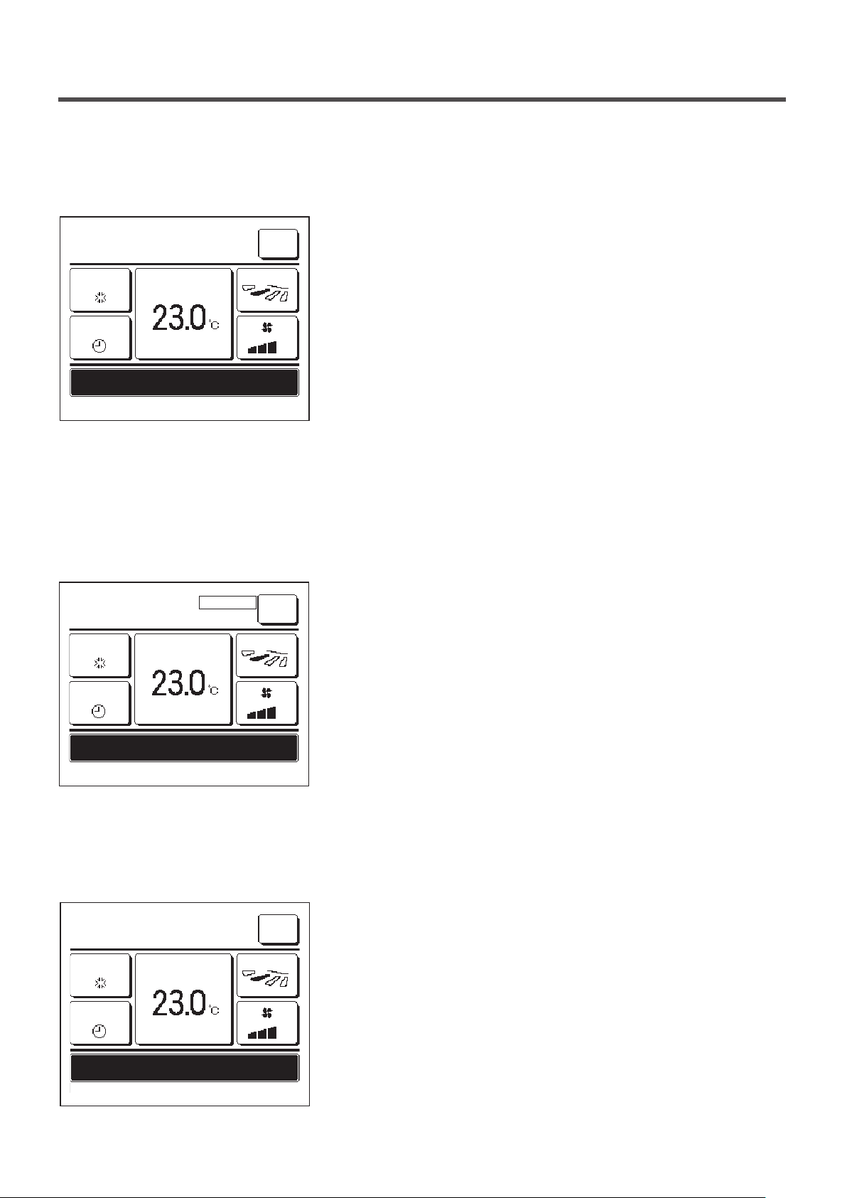
“
In operation for rotation.”, “In operation for capacity back-up”,
■
“
In operation for fault back-up” displays
When rotation, capacity back-up, or fault back-up operation is enabled
16:32
(Mon)
Cooling
Set temp
Menu
Direction
during installation, a message indicating the operation that is set and
running will be displayed on the message display.
Refer to the installation manual on how to make these settings.
Timer
In operation for rotation.
F1: High power F2: Energy-saving
“
Invalid request. Central control active.” display
■
When the unit is controlled through a central control device (not included), and you performed an operation other than
the followings, the message “Invalid request. Central control active.” is displayed.
This does not indicate a failure; the message indicates that the unit is
controlled through a central control device.
16:32
(Mon)
Cooling
Set temp
CENTER
Menu
Direction
[Operations allowed during central control]
Timer
Invalid request. Central control active.
F1: High power F2: Energy-saving
“In temporary stop mode”, “In forced thermostat OFF”, “In setting
■
Filter sign reset
・
Administrator settings
・
temperature shift” displays
These messages will be displayed when the unit is operated through IO
16:32
(Mon)
Cooling
Set temp
Menu
Direction
external input.
This does not indicate a failure; the message indicates that the unit is
operated through IO external input.
Timer
In temporary stop mode
F1: High power F2: Energy-saving
- 71 -
Page 74

“OU silent operation by external input” display
■
The message “OU silent operation by external input” will be displayed when silent mode control is operated through a
central control device (not included) or an IO external input (not included).
MEETING1
16:00
(Mon)
Auto
Timer
OU silent operation by external input
F1: High power F2: Energy-saving
“There is a information of maintenance. Check the content from [Menu].” display
■
Set temp
Room
Menu
Direction
When “OU silent operation by external input” is displayed, the operation
performed will be the same as the silent mode control (☞page 64)
performed from the R/C.
During silent mode control, operation with maximum capacity is not
allowed.
To notify any maintenance information related to the product, the
20:20 (Tue)
Heating
Timer
Set temp
Menu
Direction
message “There is a information of maintenance. Check the content
from [Menu].” may be displayed in the message display.
When this message is displayed, tap the
Menu
button. The
maintenance description will be displayed.
There is a information of maintenance.
Check the content from [Menu].
F1: High power F2: Energy-saving
“
Back-up” display
■
Contact the dealer/company shown as the Contact company (☞page
68) and notify the details (code) of required maintenance.
When any error occurs on the OU but its operation is continued as an emergency measure, the message of “Back-up”
will be displayed.
MEETING1
16:41
(Mon)
Cooling
Timer
Back-up
F1: High power F2: Energy-saving
Set temp
Menu
Direction
When the “Back-up” is displayed, contact dealer/company shown as the
Contact company (☞page 68) immediately for checking.
■If the operation is continued without checking, it could result in breakdown.
- 72 -
Page 75

9. After-sale service
● Inform your dealer
●Model name
●Date of installation
●Failure conditions:
●Your address, name, and telephone number
As precise as possible.
● Moving
The moving of the unit requires special technology. Consult your
dealer.
Necessary expenses for the moving of the unit will be charged.
● Repairs after Warranty Period
Consult your dealer. Fare-paying services may be possible at
the request of customer.
(The warranty period is one year counting from the date of
installation.)
● Inquiry about After-sale Service
Contact your dealer or the service contact.
- 73 -
 Loading...