


SAFETY PRECAUTIONS
(Read these precautions before use.)
Before using this product, please read this manual carefully and pay full attention to safety to handle the
product correctly.
The precautions given in this manual are concerned with this product. For the safety precautions of the
programmable controller system, please read the User's Manual for the CPU module.
In this section, the safety precautions are ranked as "DANGER" and "CAUTION".
DANGER
CAUTION
Note that the CAUTION level may lead to a serious consequence according to the circumstances.
Always follow the precautions of both levels because they are important to personal safety.
Please save this manual to make it accessible when required and always forward it to the end user.
Indicates that incorrect handling may cause hazardous conditions,
resulting in death or severe injury.
Indicates that incorrect handling may cause hazardous conditions,
resulting in medium or slight personal injury or physical damage.
[DESIGN PRECAUTIONS]
DANGER
Do not write data to "read-only area" or "reserved area" in the buffer memory of the intelligent
function module. Also do not turn ON/OFF the "reserved" signal in I/O signals to the programmable
controller CPU.
Doing any of these operations may cause a malfunction of the programmable controller system.
CAUTION
Do not install the control lines and/or pulse input wiring together with the main circuit or power lines,
and also do not bring them close to each other.
Keep a distance of 150 mm (5.91 inch) or more between them.
Failure to do so may cause a malfunction due to noise.
[INSTALLATION PRECAUTIONS]
CAUTION
Use the programmable controller in the environment conditions given in the general specifications of
the User's Manual for the CPU module.
Failure to do so may cause an electric shock, fire, malfunction, or damage to or deterioration of the
product.
A - 1
[INSTALLATION PRECAUTIONS]
CAUTION
While pressing the installation lever located at the bottom of the module, fully insert the module fixing
projection into the fixing hole in the base unit and press the module using the hole as a fulcrum.
Incorrect module mounting may cause a malfunction, failure, or drop of the module.
In an environment of frequent vibrations, secure the module with screws.
The screws must be tightened within the specified torque range.
If the screw is too loose, it may cause a drop, short circuit, or malfunction.
Excessive tightening may damage the screw and/or the module, resulting in a drop, short circuit or
malfunction.
Be sure to shut off all phases of the external power supply used by the system before mounting or
removing the module.
Failure to do so may cause damage to the product.
Do not directly touch any conductive part or electronic part of the module.
Doing so may cause a malfunction or failure of the module.
[WIRING PRECAUTIONS]
CAUTION
When wiring/connecting the connector, properly press, crimp or solder the connector using the tools
specified by the manufacturers and attach the connector to the module securely.
Be careful to prevent foreign matter such as dust or wire chips from entering the module.
Failure to do may cause a fire, failure or malfunction.
A protective film is attached to the module top to prevent foreign matter such as wire chips from
entering the module during wiring.
Do not remove the film during wiring.
Be sure to remove it for heat dissipation before system operation.
Be sure to place the cables connected to the module in a duct or clamp them.
If not, dangling cables may swing or inadvertently be pulled, resulting in damage to the module and/
or cables, or malfunctions due to poor cable connection.
When disconnecting the cable, do not pull it by holding the cable part.
Disconnect the cable with connector with holding the connector plugged into the module.
Pulling the cable part with the cable still connected to the module may cause a malfunction or
damage to the module and/or cable.
A - 2
[WIRING PRECAUTIONS]
CAUTION
Always ground the shielded cable on the encoder side (relay box).
Failure to do may cause a malfunction.
Correctly wire cables to the module after checking the rated voltage and terminal layout of the
product.
Connecting a voltage different from the rated voltage or incorrect wiring may result in a fire or failure.
[STARTUP/MAINTENANCE PRECAUTIONS]
CAUTION
Do not disassemble or remodel each of the modules.
Doing so may cause failure, malfunctions, personal injuries and/or a fire.
Be sure to shut off all phases of the external power supply used by the system before mounting or
removing the module.
Not doing so may result in a failure or malfunction of the module.
Do not mount/remove the module onto/from the base unit more than 50 times (IEC 61131-2compliant), after the first use of the product.
Doing so may cause malfunctions.
Do not touch the terminal while the power is ON. Failure to do may cause a malfunction.
Switch off all phases of the externally supplied powerused in the system when cleaning the module
or retightening the terminal or module fixing screws.
Not doing so may result in a failure or malfunction of the module.
If the screw is too loose, it may cause a drop, short circuit or malfunction.
Excessive tightening may damage the screw and/or the module, resulting in a drop, short circuit or
malfunction.
Before handling the module, touch a grounded metal object to discharge the static electricity from
the human body.
Not doing so may result in a failure or malfunction of the module.
[DISPOSAL PRECAUTIONS]
CAUTION
When disposing of this product, treat it as industrial waste.
A - 3

REVISIONS
* The manual number is given on the bottom left of the back cover.
Print date *Manual number Revision
Jun., 2007 SH(NA)-080692ENG-A First edition
Correction
Jan., 2008 SH(NA)-080692ENG-B
CONTENTS, GENERIC TERMS AND ABBREVIATIONS, Section 2.1 to 2.3,
Section 4.1, Section 6.2.1, Section 6.2.2, Section 6.2.3, Section 6.3.1 to 6.3.3,
Section 6.4 to 6.6
Japanese Manual Version SH-080693-B
This manual confers no industrial property rights or any rights of any other kind, nor does it confer any licenses. Mitsubishi
Electric Corporation cannot be held responsible for any problems involving industrial property rights which may occur as a
result of using the contents noted in this manual.
2007 MITSUBISHI ELECTRIC CORPORATION
A - 4

INTRODUCTION
Thank you for purchasing the Mitsubishi programmable controller MELSEC-Q series.
Before using the product, please read this manual carefully to develop full familiarity with the functions and
performance of the Q series programmable controller to ensure correct use.
CONTENTS
SAFETY PRECAUTIONS•••••••••••••••••••••••••••••••••••••••••••••••••••••••••••••••••••••••••••••••••••••••••••••••••••••• A - 1
REVISIONS•••••••••••••••••••••••••••••••••••••••••••••••••••••••••••••••••••••••••••••••••••••••••••••••••••••••••••••••••••••••A - 4
INTRODUCTION •••••••••••••••••••••••••••••••••••••••••••••••••••••••••••••••••••••••••••••••••••••••••••••••••••••••••••••••• A - 5
CONTENTS••••••••••••••••••••••••••••••••••••••••••••••••••••••••••••••••••••••••••••••••••••••••••••••••••••••••••••••••••••••• A - 5
Compliance with the EMC and Low Voltage Directives •••••••••••••••••••••••••••••••••••••••••••••••••••••••••••••••••• A - 8
GENERIC TERMS AND ABBREVIATIONS •••••••••••••••••••••••••••••••••••••••••••••••••••••••••••••••••••••••••••••••• A - 9
PACKING LIST••••••••••••••••••••••••••••••••••••••••••••••••••••••••••••••••••••••••••••••••••••••••••••••••••••••••••••••••••• A - 9
CHAPTER1 OVERVIEW 1 - 1 to 1 - 2
1.1 Features •••••••••••••••••••••••••••••••••••••••••••••••••••••••••••••••••••••••••••••••••••••••••••••••••••••••••••••• 1 - 2
CHAPTER2 SYSTEM CONFIGURATION 2 - 1 to 2 - 6
2.1 Applicable Systems••••••••••••••••••••••••••••••••••••••••••••••••••••••••••••••••••••••••••••••••••••••••••••••••• 2 - 1
2.2 About Use of the QD63P6 with the Q12PRH/Q25PRHCPU •••••••••••••••••••••••••••••••••••••••••••••••2 - 4
2.3 How to Check the Software Version •••••••••••••••••••••••••••••••••••••••••••••••••••••••••••••••••••••••••••• 2 - 5
CHAPTER3 SPECIFICATIONS 3 - 1 to 3 - 18
3.1 Performance Specifications••••••••••••••••••••••••••••••••••••••••••••••••••••••••••••••••••••••••••••••••••••••• 3 - 1
3.2 Function List ••••••••••••••••••••••••••••••••••••••••••••••••••••••••••••••••••••••••••••••••••••••••••••••••••••••••• 3 - 2
3.3 I/O Signals to the Programmable Controller CPU •••••••••••••••••••••••••••••••••••••••••••••••••••••••••••• 3 - 3
3.3.1 I/O signal list ••••••••••••••••••••••••••••••••••••••••••••••••••••••••••••••••••••••••••••••••••••••••••••••••••• 3 - 3
3.3.2 Functions of I/O signals •••••••••••••••••••••••••••••••••••••••••••••••••••••••••••••••••••••••••••••••••••••• 3 - 5
3.4 Buffer Memory Assignment ••••••••••••••••••••••••••••••••••••••••••••••••••••••••••••••••••••••••••••••••••••••• 3 - 9
3.4.1 List of buffer memory assignment•••••••••••••••••••••••••••••••••••••••••••••••••••••••••••••••••••••••••• 3 - 9
3.4.2 Details of the buffer memory •••••••••••••••••••••••••••••••••••••••••••••••••••••••••••••••••••••••••••••• 3 - 11
3.5 Interface with External Devices •••••••••••••••••••••••••••••••••••••••••••••••••••••••••••••••••••••••••••••••• 3 - 17
3.6 Connectable Encoders••••••••••••••••••••••••••••••••••••••••••••••••••••••••••••••••••••••••••••••••••••••••••• 3 - 18
CHAPTER4 PROCEDURES AND SETTINGS BEFORE OPERATION 4 - 1 to 4 - 16
4.1 Handling Precautions ••••••••••••••••••••••••••••••••••••••••••••••••••••••••••••••••••••••••••••••••••••••••••••••4 - 1
4.2 Procedures before Operation••••••••••••••••••••••••••••••••••••••••••••••••••••••••••••••••••••••••••••••••••••• 4 - 2
4.3 Part Names •••••••••••••••••••••••••••••••••••••••••••••••••••••••••••••••••••••••••••••••••••••••••••••••••••••••••• 4 - 3
4.4 Wiring ••••••••••••••••••••••••••••••••••••••••••••••••••••••••••••••••••••••••••••••••••••••••••••••••••••••••••••••••• 4 - 5
4.4.1 Wiring precautions •••••••••••••••••••••••••••••••••••••••••••••••••••••••••••••••••••••••••••••••••••••••••••• 4 - 5
4.4.2 Example of wiring the module and an encoder•••••••••••••••••••••••••••••••••••••••••••••••••••••••••• 4 - 8
A - 5

4.5 Intelligent Function Module Switch Setting••••••••••••••••••••••••••••••••••••••••••••••••••••••••••••••••••• 4 - 14
CHAPTER5 FUNCTIONS 5 - 1 to 5 - 22
5.1 Pulse Input and Count Methods•••••••••••••••••••••••••••••••••••••••••••••••••••••••••••••••••••••••••••••••••• 5 - 1
5.1.1 Types of the pulse input method ••••••••••••••••••••••••••••••••••••••••••••••••••••••••••••••••••••••••••• 5 - 1
5.2 Selecting Counter Format ••••••••••••••••••••••••••••••••••••••••••••••••••••••••••••••••••••••••••••••••••••••••• 5 - 3
5.2.1 Selecting the linear counter •••••••••••••••••••••••••••••••••••••••••••••••••••••••••••••••••••••••••••••••••5 - 4
5.2.2 Selecting the ring counter ••••••••••••••••••••••••••••••••••••••••••••••••••••••••••••••••••••••••••••••••••• 5 - 5
5.3 Using the Coincidence Detection Function •••••••••••••••••••••••••••••••••••••••••••••••••••••••••••••••••• 5 - 12
5.4 Using the Preset Function••••••••••••••••••••••••••••••••••••••••••••••••••••••••••••••••••••••••••••••••••••••• 5 - 17
5.5 Using the Periodic Pulse Counter Function•••••••••••••••••••••••••••••••••••••••••••••••••••••••••••••••••• 5 - 18
5.6 Count Response Delay Time ••••••••••••••••••••••••••••••••••••••••••••••••••••••••••••••••••••••••••••••••••• 5 - 22
CHAPTER6 UTILITY PACKAGE (GX Configurator-CT) 6 - 1 to 6 - 20
6.1 Utility Package Functions ••••••••••••••••••••••••••••••••••••••••••••••••••••••••••••••••••••••••••••••••••••••••• 6 - 1
6.2 Installing and Uninstalling the Utility Package ••••••••••••••••••••••••••••••••••••••••••••••••••••••••••••••••• 6 - 2
6.2.1 Handling precautions ••••••••••••••••••••••••••••••••••••••••••••••••••••••••••••••••••••••••••••••••••••••••• 6 - 2
6.2.2 Operating environment ••••••••••••••••••••••••••••••••••••••••••••••••••••••••••••••••••••••••••••••••••••••• 6 - 4
6.3 Utility Package Operation ••••••••••••••••••••••••••••••••••••••••••••••••••••••••••••••••••••••••••••••••••••••••• 6 - 6
6.3.1 Common utility package operations ••••••••••••••••••••••••••••••••••••••••••••••••••••••••••••••••••••••• 6 - 6
6.3.2 Operation overview •••••••••••••••••••••••••••••••••••••••••••••••••••••••••••••••••••••••••••••••••••••••••••6 - 8
6.3.3 Starting the Intelligent function module utility •••••••••••••••••••••••••••••••••••••••••••••••••••••••••• 6 - 10
6.4 Initial Setting ••••••••••••••••••••••••••••••••••••••••••••••••••••••••••••••••••••••••••••••••••••••••••••••••••••••• 6 - 13
6.5 Auto Refresh ••••••••••••••••••••••••••••••••••••••••••••••••••••••••••••••••••••••••••••••••••••••••••••••••••••••• 6 - 15
6.6 Monitoring/Test •••••••••••••••••••••••••••••••••••••••••••••••••••••••••••••••••••••••••••••••••••••••••••••••••••• 6 - 17
6.6.1 Monitoring/Test •••••••••••••••••••••••••••••••••••••••••••••••••••••••••••••••••••••••••••••••••••••••••••••• 6 - 17
CHAPTER7 PROGRAMMING 7 - 1 to 7 - 14
7.1 Program Example when GX Configurator-CT is Used•••••••••••••••••••••••••••••••••••••••••••••••••••••••7 - 3
7.1.1 GX Configurator-CT operation •••••••••••••••••••••••••••••••••••••••••••••••••••••••••••••••••••••••••••••• 7 - 3
7.1.2 Program example ••••••••••••••••••••••••••••••••••••••••••••••••••••••••••••••••••••••••••••••••••••••••••••• 7 - 5
7.2 Program Example when GX Configurator-CT is not Used •••••••••••••••••••••••••••••••••••••••••••••••••• 7 - 7
7.2.1 Program example when dedicated instructions are used ••••••••••••••••••••••••••••••••••••••••••••• 7 - 7
7.2.2 Program example when dedicated instructions are not used••••••••••••••••••••••••••••••••••••••• 7 - 10
7.3 Program Example when the Coincidence Detection Interrupt Function is Used ••••••••••••••••••••• 7 - 13
CHAPTER8 TROUBLESHOOTING 8 - 1 to 8 - 9
8.1 Error Processing and Recovery Methods •••••••••••••••••••••••••••••••••••••••••••••••••••••••••••••••••••••• 8 - 1
8.1.1 Checking error description using System Monitor of GX Developer •••••••••••••••••••••••••••••••• 8 - 1
8.1.2 When the RUN LED turns OFF•••••••••••••••••••••••••••••••••••••••••••••••••••••••••••••••••••••••••••••8 - 4
8.1.3 When the RUN LED and ERR. LED turn ON •••••••••••••••••••••••••••••••••••••••••••••••••••••••••••• 8 - 4
8.2 When the QD63P6 Does Not Start Counting ••••••••••••••••••••••••••••••••••••••••••••••••••••••••••••••••••8 - 5
A - 6

8.3 When the QD63P6 Does Not Normally Count •••••••••••••••••••••••••••••••••••••••••••••••••••••••••••••••• 8 - 6
8.4 When the Coincidence Detection Interrupt Does Not Occur ••••••••••••••••••••••••••••••••••••••••••••••• 8 - 7
8.5 Error Codes List ••••••••••••••••••••••••••••••••••••••••••••••••••••••••••••••••••••••••••••••••••••••••••••••••••••• 8 - 8
APPENDICES App - 1 to App - 5
Appendix 1 Dedicated Instructions •••••••••••••••••••••••••••••••••••••••••••••••••••••••••••••••••••••••••••••••• App - 1
Appendix 1.1 Dedicated instructions list•••••••••••••••••••••••••••••••••••••••••••••••••••••••••••••••••••••• App - 1
Appendix 1.2 G(P). PPCVRD••••••••••••••••••••••••••••••••••••••••••••••••••••••••••••••••••••••••••••••••••• App - 2
Appendix 2 External Dimensions •••••••••••••••••••••••••••••••••••••••••••••••••••••••••••••••••••••••••••••••••• App - 5
INDEX Index - 1 to Index - 2
A - 7

Compliance with the EMC and Low Voltage Directives
When incorporating the Mitsubishi programmable controller into other machinery or
system and ensuring compliance with the EMC and Low Voltage Directives, refer to
Chapter 3 "EMC and Low Voltage Directive" in the User's Manual (Hardware) of the
programmable controller CPU included with the CPU module or base unit.
The CE logo is printed on the rating plate of the programmable controller, indicating
compliance with the EMC and Low Voltage Directives.
To conform this product to the EMC and Low Voltage Directives, refer to "CHAPTER 4
PROCEDURES AND SETTINGS BEFORE OPERATION (Section 4.4.1 Wiring
precautions)".
A - 8
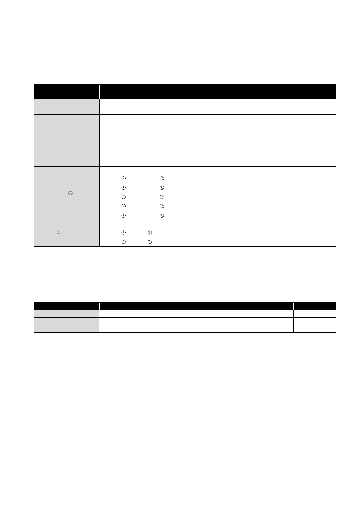
GENERIC TERMS AND ABBREVIATIONS
This manual describes the type QD63P6 multichannel high-speed counter module using
the following generic terms and abbreviations, unless otherwise specified.
Generic term and
abbreviation
QD63P6 Abbreviation for the type QD63P6 multichannel high-speed counter module
Personal computer Generic term for IBM-PC/AT-compatible personal computer
Generic product name for SWnD5C-GPPW-E, SWnD5C-GPPW-EA, SWnD5C-GPPW-EV, and SWnD5C-
GX Developer
QCPU (Q mode)
GX Configurator-CT Abbreviation for GX Configurator-CT (SW0D5C-QCTU-E) of counter module setting/monitor tool
Windows Vista
Windows XP
GPPW-EVA
("n" is 4 or greater.)
"-A" and "-V" denote volume license product and upgraded product respectively.
Generic term for the Q00JCPU, Q00CPU, Q01CPU, Q02CPU, Q02HCPU, Q06HCPU, Q12HCPU,
Q25HCPU, Q12PHCPU, Q25PHCPU, Q02UCPU, Q03UDCPU, Q04UDHCPU, and Q06UDHCPU
Generic term for the following:
Microsoft Windows Vista Home Basic Operating System,
Microsoft Windows Vista Home Premium Operating System,
Microsoft Windows Vista Business Operating System,
Microsoft Windows Vista Ultimate Operating System,
Microsoft Windows Vista Enterprise Operating System
Generic term for the following:
Microsoft Windows XP Professional Operating System,
Microsoft Windows XP Home Edition Operating System
Description
PACKING LIST
The following are included in the package.
Model Product name Quantity
QD63P6 Type QD63P6 multichannel high-speed counter module 1
SW0D5C-QCTU-E GX Configurator-CT Version 1 (single license product) (CD-ROM) 1
SW0D5C-QCTU-AE GX Configurator-CT Version 1 (volume license product)(CD-ROM) 1
A - 9
1
OVERVIEW
CHAPTER1 OVERVIEW
This User's Manual describes the specifications, handling, and programming methods for
the type QD63P6 multichannel high-speed counter module used together with the
MELSEC-Q series CPU module.
The QD63P6 can use the following methods in 1-phase/2-phase pulse inputs.
•1 multiple of 1 phase pulse
input
•1 multiple of 2 phases pulse
input
•2 multiples of 1 phase pulse
input
•2 multiples of 2 phases pulse
input
•CW/CCW
•4 multiples of 2 phases pulse
input
For details of the input methods, refer to Section 5.1.
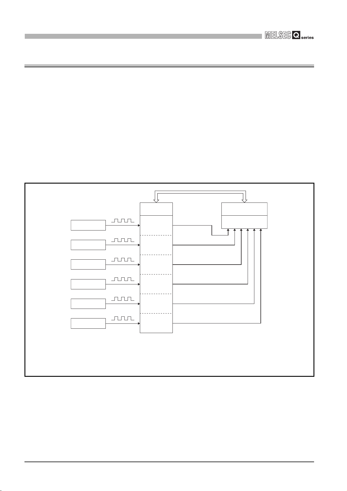
Figure 1.1 shows the general operation of the QD63P6.
2) Reading/writing
Encoder
Encoder
Encoder
Encoder
Encoder
Encoder
Pulse
Pulse
Pulse
Pulse
Pulse
Pulse
QD63P6
CH11)
CH21)
CH31)
CH41)
CH51)
CH61)
the I/O signals and
buffer memory
3)
3)
3)
3)
3)
3)
Programmable
controller CPU
QCPU (Q mode)
1 - 1
1) Pulses input to the QD63P6 are counted.
2) The status of the I/O signals and buffer memory of the QD63P6 can be checked with the
sequence program.
Also, start, stop, preset, and coincidence detection of the count can be executed.
3) An interrupt request can be executed to the programmable controller CPU at counter
value coincidence detection.
Figure 1.1 General operation of the QD63P6

1
OVERVIEW
1.1 Features
1
This section describes the features of the QD63P6.
(1) Wide range of expression on counting (from -2147483648 to 2147483647)
Count values can be stored in 6 channels and 32-bit signed binary.
(2) Switching of the maximum counting speed
Since the QD63P6 can switch between 200 k, 100 k, and 10 k, gradual rise/fall
pulses can be correctly counted.
(3) Pulse input selection
Pulse input can be selected from 1 multiple of 1 phase, 2 multiples of 1 phase, 1
multiple of 2 phases, 2 multiples of 2 phases, 4 multiples of 2 phases, and CW/CCW.
(4) Counter format selection
Either of the following counter formats can be selected.
(a) Linear counter format
From -2147483648 to 2147483647 can be counted and an overflow can be
detected when the count range is overrun.
(b) Ring counter format
Counts are repeatedly executed between the ring counter upper limit value and
ring counter lower limit value.
(5) Coincidence detection
By presetting the coincidence detection point of an arbitrary channel, the detection
point is compared to the present counter value, ON/OFF signal can be output
according to the result, and an interrupt program can be started.
(6) The periodic pulse counter function is supported.
The periodic pulse counter function stores the present and previous counter values at
every preset time while signals are input.
OVERVIEW
2
SYSTEM
CONFIGURATION
3
SPECIFICATIONS
4
PROCEDURES AND
SETTINGS BEFORE
OPERATION
5
FUNCTIONS
6
(7) Simple settings using the utility package
The utility package (GX Configurator-CT) is sold separately.
Although the usage of the utility package is arbitrary, it enables to make initial settings
and auto refresh setting on the screen, which lead to load reduction of the sequence
programs and simplicity in checking the setting status and operation status.
1.1 Features
1 - 2
UTILITY PACKAGE
7
8
(GX Configurator-CT)
PROGRAMMING
TROUBLESHOOTING
2
SYSTEM CONFIGURATION
CHAPTER2 SYSTEM CONFIGURATION
This chapter describes system configurations for the QD63P6.
2.1 Applicable Systems
This section describes the applicable systems.
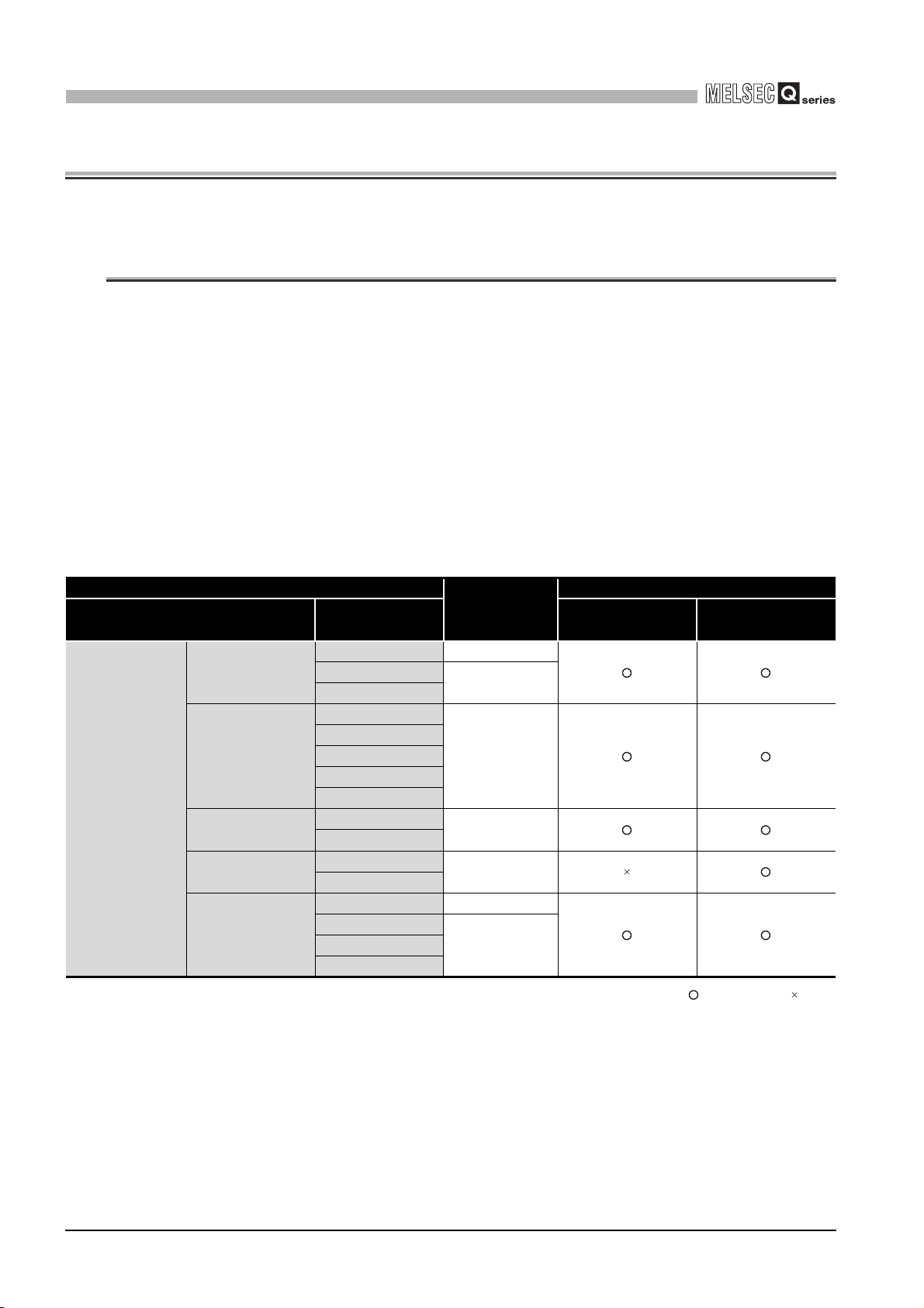
(1) Applicable modules and base units, and No. of modules
(a) When mounted with a CPU module
The table below shows the CPU modules and base units applicable to the
QD63P6 and quantities for each CPU model.
Depending on the combination with other modules or the number of mounted
modules, power supply capacity may be insufficient.
Pay attention to the power supply capacity before mounting modules, and if the
power supply capacity is insufficient, change the combination of the modules.
Programmable
controller CPU
Table 2.1 Applicable modules and the number of mountable modules
Applicable CPU module
CPU type CPU model Main base unit
Basic model
QCPU*3
High Performance
model QCPU
Process CPU
Redundant CPU
Universal model
QCPU
Q00JCPU Up to 8
Q00CPU
Q01CPU
Q02CPU
Q02HCPU
Q06HCPU
Q12HCPU
Q25HCPU
Q12PHCPU
Q25PHCPU
Q12PRHCPU
Q25PRHCPU
Q02UCPU Up to 36
Q03UDCPU
Q06UDHCPU
No. of
modules*1
Up to 24
Up to 64
Up to 64
Up to 53
Up to 64Q04UDHCPU
Base unit*2
Extension base
unit
: Applicable : N/A
2 - 1
* 1 Limited within the range of I/O points for the CPU module.
* 2 Can be installed to any I/O slot of a base unit.
* 3 For the coincidence detection interrupt function, use the CPU module of function version B or later.
2.1 Applicable Systems
2
SYSTEM CONFIGURATION
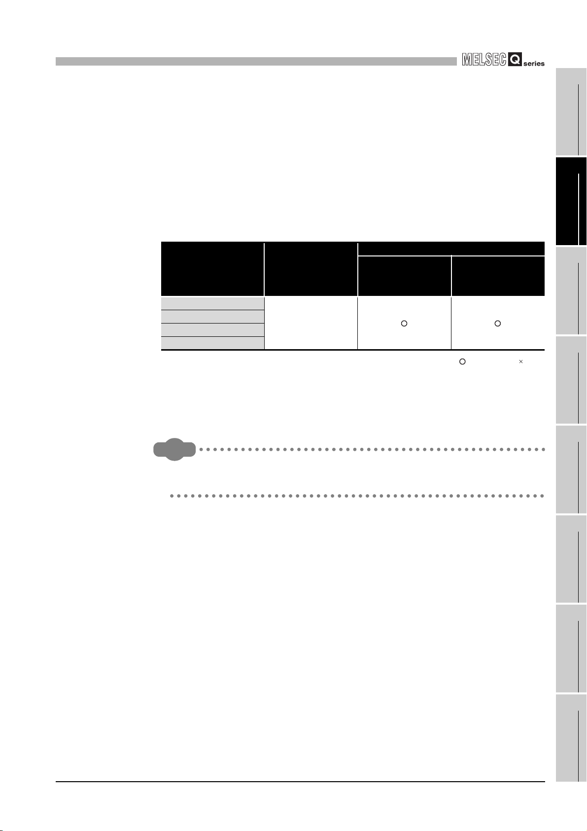
(b) Mounting to a MELSECNET/H remote I/O station
The following table shows network modules that can be mounted to the QD63P6,
the number of mountable network modules, and applicable base units.
The QD63P6 module can be mounted into any I/O slots
unit.
However, the power capacity may be insufficient depending on the combination
with the other mounted modules and the number of mounted modules.
Be sure to check the power capacity when mounting the modules.
*1
on the applicable base
1
OVERVIEW
2
Table 2.2 Mountable network modules, No. of mountable modules, and mountable base unit
Applicable base unit*2
the remote I/O
station
Extension base unit
on the remote I/O
Mountable network
module*3*4
QJ72LP25-25
QJ72LP25G
QJ72LP25GE
QJ72BR15
* 1 Limited within the range of I/O points for the network module.
* 2 Can be installed to any I/O slot of a base unit.
* 3 The coincidence detection interrupt function is not supported.
* 4 The dedicated instructions are not supported.
Remark
The Basic model QCPU cannot configure the MELSECNET/H remote I/O network
system.
Number of
mountable
modules*1
Up to 64
Main base unit on
station
: Applicable : N/A
SYSTEM
CONFIGURATION
3
SPECIFICATIONS
4
PROCEDURES AND
SETTINGS BEFORE
OPERATION
5
FUNCTIONS
6
2.1 Applicable Systems
2 - 2
UTILITY PACKAGE
7
8
(GX Configurator-CT)
PROGRAMMING
TROUBLESHOOTING
2
SYSTEM CONFIGURATION
(2) Support of the multiple CPU system
The function version of the first released QD63P6 is B, and it supports multiple CPU
systems.
When using the QD63P6 in a multiple CPU system, refer to the following manual first.
• QCPU User's Manual (Multiple CPU System)
(a) Intelligent function module parameters
Write intelligent function module parameters to only the control CPU of the
QD63P6.
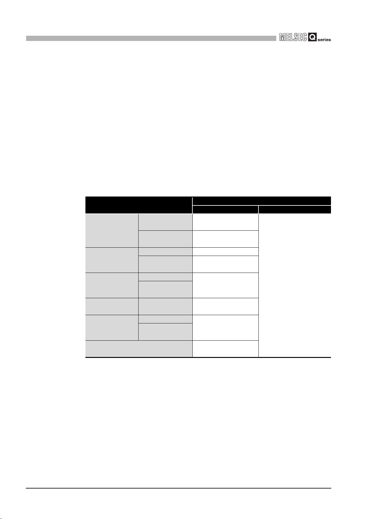
(3) Supported software packages
Relation between the system containing the QD63P6 and software package is shown
in the following table.
GX Developer is necessary when using the QD63P6.
Item
Single CPU
Q00J/Q00/Q01CPU
Q02/Q02H/Q06H/
Q12H/Q25HCPU
Q12PH/
Q25PHCPU
Q12PRH/
Q25PRHCPU
Q02U/Q03UD/
Q04UDH/
Q06UDHCPU
When mounted to the MELSECNET/H
remote I/O station
system
Multiple CPU
system
Single CPU system Version 4 or later
Multiple CPU
system
Single CPU system
Multiple CPU
system
Redundant CPU
system
Single CPU system
Multiple CPU
system
Table 2.3 Software package version
Software version
GX Developer GX Configurator-CT
Version 7 or later
Version 8 or later
Version 6 or later
Version 7.10L or later
Version 8.45X or later
Version 8.48A or later
Version 6 or later
Version 1.25AB or later
2 - 3
(4) Connector
The connector is not included with the QD63P6.
Purchase it with reference to Section 4.3.
2.1 Applicable Systems

2
SYSTEM CONFIGURATION
2.2 About Use of the QD63P6 with the Q12PRH/Q25PRHCPU
Here, use of the QD63P6 with the Q12PRH/Q25PRHCPU is explained.
1
(1) Dedicated instruction
The dedicated instruction cannnot be used.
(2) GX Configurator-CT
GX Configurator-CT cannot be used when accessing the Q12PRH/Q25PRHCPU via
an intelligent function module on an extension base unit from GX Developer.
Connect a personal computer with a communication path indicated below
1 2
Main base unit
Extension base unit
(GX Configurator-CT cannot be used.)
OVERVIEW
2
SYSTEM
CONFIGURATION
3
SPECIFICATIONS
4
PROCEDURES AND
SETTINGS BEFORE
OPERATION
5
Direct connection to the CPU
1
Connection through an intelligent function module on the main base unit
2
(Through Ethernet module, MELSECNET/H module, or CC-Link module)
Figure 2.1 Communication path which GX Configrator-CT can use
FUNCTIONS
6
UTILITY PACKAGE
(GX Configurator-CT)
7
PROGRAMMING
8
2.2 About Use of the QD63P6 with the Q12PRH/Q25PRHCPU
TROUBLESHOOTING
2 - 4
2
SYSTEM CONFIGURATION
2.3 How to Check the Software Version
This section describes how to check the function version of the QD63P6 and software
version of GX Configurator-CT.
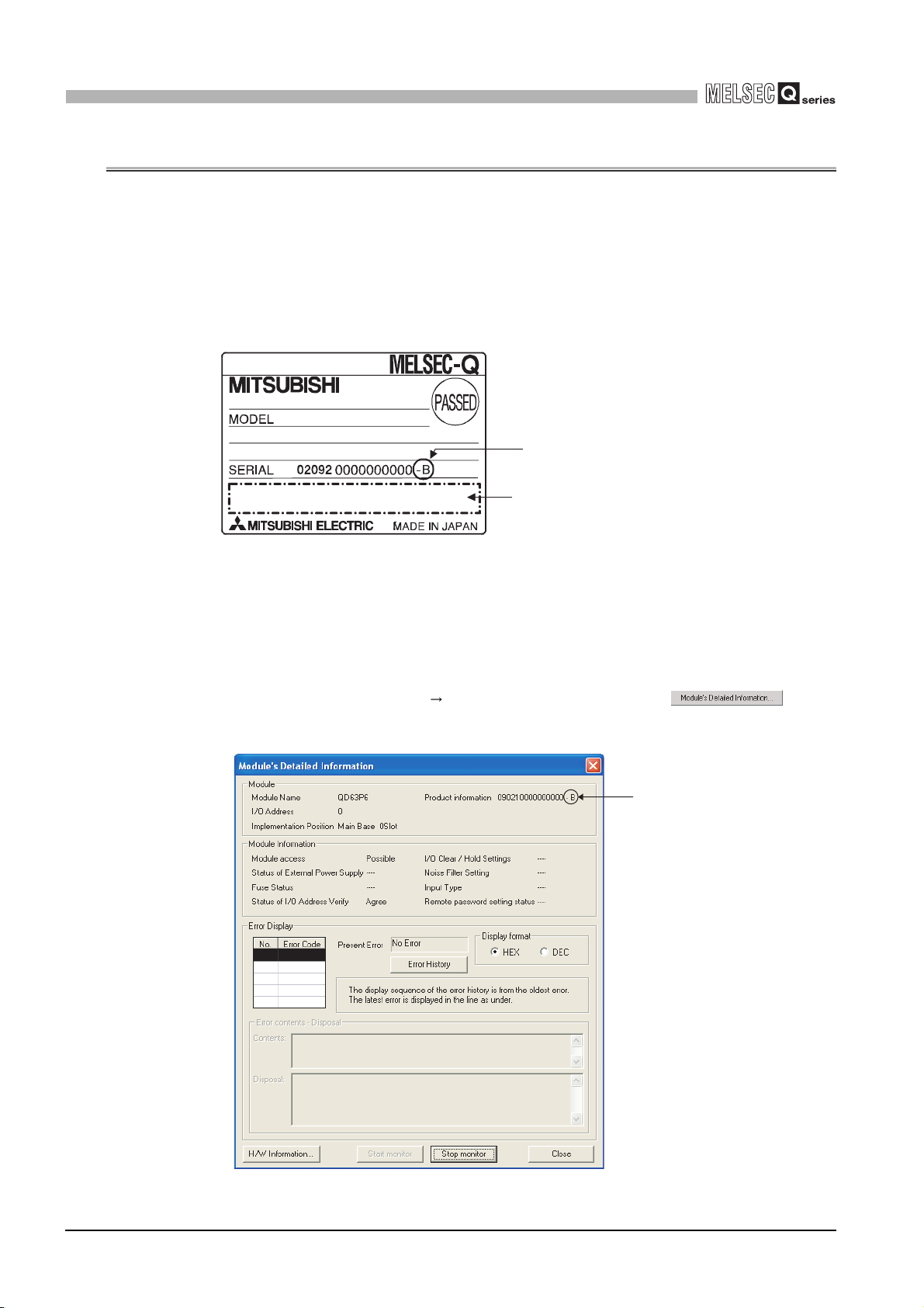
(1) Checking the function version of the QD63P6
(a) Checking the rating plate on the module side
Check the version by the last character of "SERIAL".
Figure 2.2 Checking the serial No. and function version (rating plate)
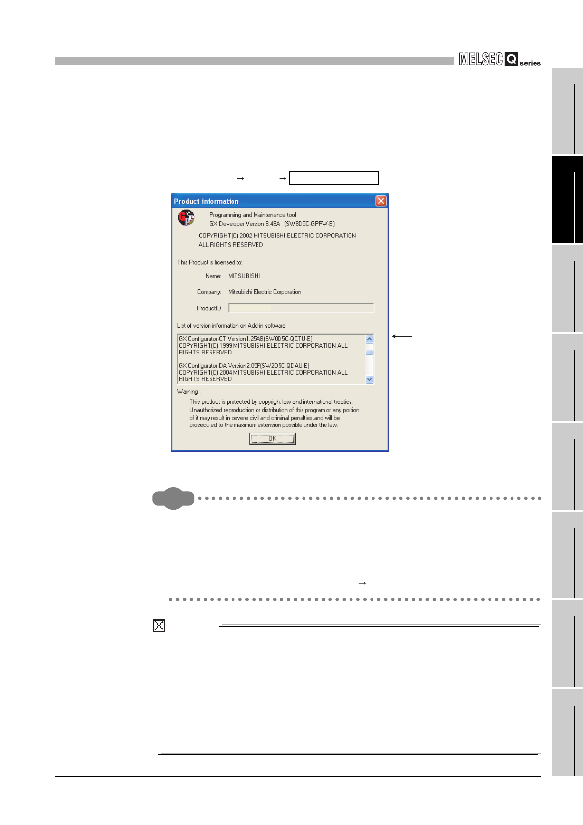
(b) Checking using GX Developer
Function version
Relevant regulation standards
Check the version by the last character displayed at [Production information] field
on the [Module's Detailed Information] dialog box of GX Developer.
[GX Developer operation]
Select [Diagnostics...] [System monitor...] and click the button
on the displayed screen.
Function version
2 - 5
Figure 2.3 [Module's Detailed Information] dialog box of GX Developer
2.3 How to Check the Software Version
2
SYSTEM CONFIGURATION
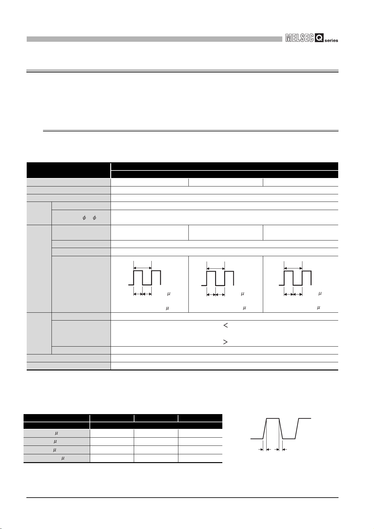
(2) Checking the software version of GX Configurator-CT
The software version of GX Configurator-CT can be checked GX Developer's
"Product information" screen.
[Operating procedure]
GX Developer "Help"
Product information
1
OVERVIEW
2
SYSTEM
CONFIGURATION
3
Remark
Software version
(In the case of GX Developer Version 8)
Figure 2.4 [Product information] screen of GX Developer
The version description for GX Configurator-CT has been changed as shown
below from SW0D5C-QCTU-E 40E upgraded product.
Existing product Products after the version upgrade
SW0D5C-QCTU-E 40E GX Configurator-CT Version 1.10L
SPECIFICATIONS
4
PROCEDURES AND
SETTINGS BEFORE
OPERATION
5
FUNCTIONS
6
UTILITY PACKAGE
(GX Configurator-CT)
7
POINT
The serial No. on the rating plate may be different from the serial No. displayed on
the product information screen of GX Developer.
• The serial No. on the rating plate indicates the management information
of the product.
• The serial No. displayed on the product information screen of GX
Developer indicates the function information of the product.
The function information of the product is updated when a new function is
added.
2.3 How to Check the Software Version
PROGRAMMING
8
TROUBLESHOOTING
2 - 6
3
SPECIFICATIONS
CHAPTER3 SPECIFICATIONS
This chapter describes the performance specifications of the QD63P6, I/O signals to the
programmable controller CPU, specifications of the buffer memory.
For general specifications of the QD63P6, refer to the User's Manual for the CPU module.
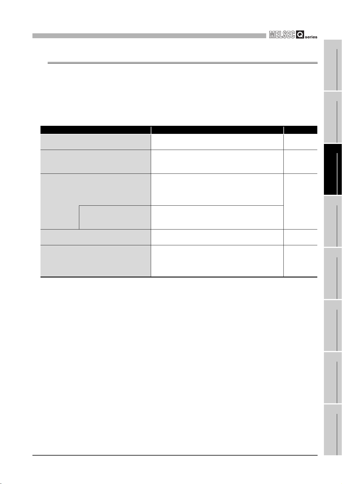
3.1 Performance Specifications
The following table shows the performance specifications of the QD63P6.
Table 3.1 Performance specifications of the QD63P6
Item
Counting speed switch setting*1 200 k (100 k to 200 kPPS) 100 k (10 k to 100 kPPS) 10 k (10 kPPS or less)
Number of occupied I/O points 32 points (I/O assignment: Intelligent 32 points)
Number of channels 6 channels
Count
input
signal
Phase 1-phase input, 2-phase input
Signal level ( A, B)
Counting speed
(max.)*2
Counting range 32-bit signed binary (-2147483648 to 2147483647)
Model UP/DOWN preset counter + Ring counter function
200 kPPS 100 kPPS 10 kPPS
Model
QD63P6
5 VDC 6.4 to 11.5 mA
Counter
Minimum count pulse
width
(Duty ratio 50 %)
(Minimum phase difference for 2-
Comparison range 32-bit signed binary
Coincide
nce
detection
5 VDC internal current consumption 0.59 A
Weight 0.15 kg
Counting speed switch setting 200 k 100 k 10 k
Comparison result
Interrupt With coincidence detection interrupt function
* 1 Make the counting speed switch setting with intelligent function module switch.
* 2 Counting speed is affected by pulse rise and fall time. Countable speeds are shown in Table 3.2.
Note if a pulse with long rise and/or fall time is counted, a miscount may occur.
Table 3.2 Relation between rise/fall time and counting speed
Rise/fall time Both 1 and 2-phase input
t = 1.25 s or less
t = 2.5 s or less
t = 25 s or less
t = 500 s
200 kPPS 100 kPPS 10 kPPS
100 kPPS 100 kPPS 10 kPPS
- 10 kPPS 10 kPPS
- - 500 PPS
5
2.5 2.5
(Unit: s)
phase input: 1.25 s)
(Minimum phase difference for
Setting value Count value
Setting value = Count value
Setting value Count value
10
5 5
2-phase input: 2.5 s)
(Unit: s)
100
50 50
(Unit: s)
(Minimum phase difference for
2-phase input: 25 s)
tt
3 - 1
3.1 Performance Specifications
3
SPECIFICATIONS
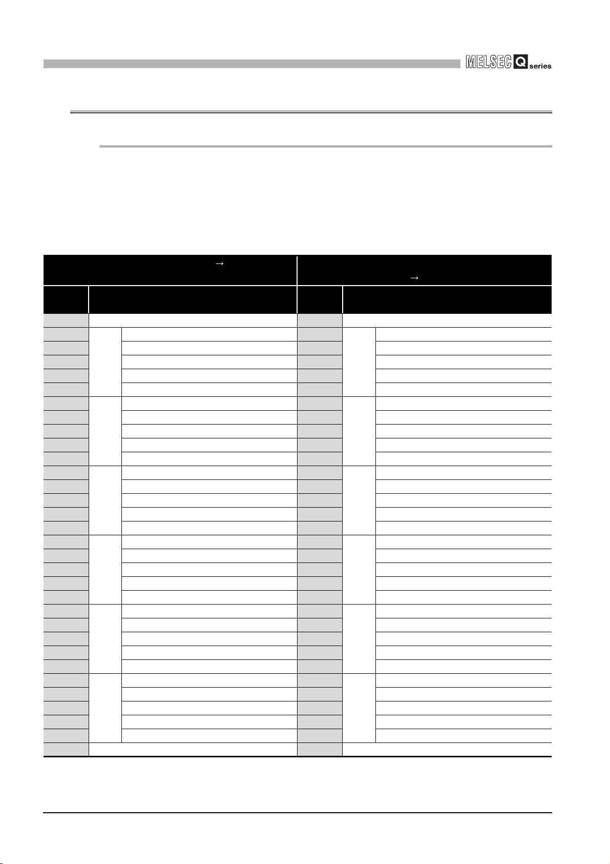
3.2 Function List
The following table shows the functions of the QD63P6.
I/O numbers (X/Y) and buffer memory addresses in Description describe only for channel
1.
For I/O numbers (X/Y) and buffer memory addresses from channels 2 to 6, refer to Section
3.3.1.
Function Description Reference
Linear counter function
Ring counter function
Coincidence detection function
Coincidence detection
interrupt function
Preset function
Periodic pulse counter function
Table 3.3 Function list of the QD63P6
Countable from -2147483648 to 2147483647 and
detects an overflow when the count range is overrun.
Repeats count between the ring counter upper limit
value (Un\G2 and 3) and ring counter lower limit value
(Un\G0 and 1).
Presets the coincidence detection point of an arbitrary
channel, compares the detection point to the present
counter value, and outputs the counter value
coincidence (X02).
Inputs the interrupt signal to the programmable controller
CPU when a coincidence is detected, and starts an
interrupt program.
Rewrites the present counter value to an arbitrary value.
Executes the preset with the sequence program.
Stores the present value A (Un\G10 and 11)/present
value B (Un\G200 and 201) in the buffer memory at
every preset period while the periodic pulse counter start
command (Y05) is input.
* The functions can be used in combination.
However, when using the linear counter function or ring counter function, select either of them.
Section 5.2.1
Section 5.2.2
Section 5.3
Section 5.4
Section 5.5
1
OVERVIEW
2
SYSTEM
CONFIGURATION
3
SPECIFICATIONS
4
PROCEDURES AND
SETTINGS BEFORE
OPERATION
5
FUNCTIONS
6
3.2 Function List
3 - 2
UTILITY PACKAGE
7
8
(GX Configurator-CT)
PROGRAMMING
TROUBLESHOOTING
3
SPECIFICATIONS
3.3 I/O Signals to the Programmable Controller CPU
3.3.1 I/O signal list
The following table shows the I/O signals from the QD63P6 to the programmable controller
CPU.
Note that that I/O numbers (X/Y) and I/O addresses mentioned in this and the subsequent
chapters are assumed when the QD63P6 is mounted to the null I/O slot on the main base
unit.
Table 3.4 I/O signal list
Input signal (Signal direction QD63P6 Programmable
controller CPU)
Device
No.
X00 Module READY Y00 Reserved
X01
X02 Counter value coincidence Y02 Preset command
X03 Counter value small Y03 Subtraction count command
X04 Reserved Y04 Count enable command
X05 Reserved Y05 Periodic pulse counter start command
X06
X07 Counter value coincidence Y07 Preset command
X08 Counter value small Y08 Subtraction count command
X09 Reserved Y09 Count enable command
X0A Reserved Y0A Periodic pulse counter start command
X0B
X0C Counter value coincidence Y0C Preset command
X0D Counter value small Y0D Subtraction count command
X0E Reserved Y0E Count enable command
X0F Reserved Y0F Periodic pulse counter start command
X10
X11 Counter value coincidence Y11 Preset command
X12 Counter value small Y12 Subtraction count command
X13 Reserved Y13 Count enable command
X14 Reserved Y14 Periodic pulse counter start command
X15
X16 Counter value coincidence Y16 Preset command
X17 Counter value small Y17 Subtraction count command
X18 Reserved Y18 Count enable command
X19 Reserved Y19 Periodic pulse counter start command
X1A
X1B Counter value coincidence Y1B Preset command
X1C Counter value small Y1C Subtraction count command
X1D Reserved Y1D Count enable command
X1E Reserved Y1E Periodic pulse counter start command
X1F Error occurrence Y1F Reserved
CH1
CH2
CH3
CH4
CH5
CH6
Signal name
Counter value large Y01
Counter value large Y06
Counter value large Y0B
Counter value large Y10
Counter value large Y15
Counter value large Y1A
Output signal (Signal direction Programmable controller
CPU QD63P6)
Device
No.
CH1
CH2
CH3
CH4
CH5
CH6
Signal name
Coincidence signal reset command
Coincidence signal reset command
Coincidence signal reset command
Coincidence signal reset command
Coincidence signal reset command
Coincidence signal reset command
3 - 3
3.3 I/O Signals to the Programmable Controller CPU
3.3.1 I/O signal list

3
SPECIFICATIONS
POINT
The reserved devices above are for system use, not for users. If used (turning
ON/OFF) by a user, the functions of the QD63P6 are not ensured.
1
OVERVIEW
2
SYSTEM
CONFIGURATION
3
SPECIFICATIONS
4
PROCEDURES AND
SETTINGS BEFORE
OPERATION
5
FUNCTIONS
6
UTILITY PACKAGE
(GX Configurator-CT)
7
PROGRAMMING
8
3.3 I/O Signals to the Programmable Controller CPU
3.3.1 I/O signal list
TROUBLESHOOTING
3 - 4
3
SPECIFICATIONS
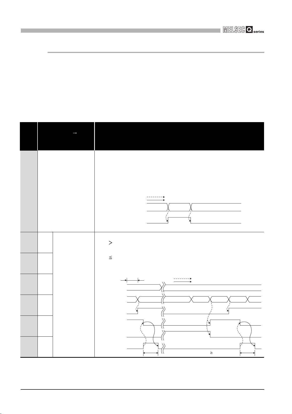
3.3.2 Functions of I/O signals
Signal name
Device
No.
X00 Module READY
QD63P6
Programmable controller
The following table shows the I/O signals of the QD63P6.
I/O numbers (X/Y) and buffer memory addresses in Description describe only for channel
1.
For I/O numbers (X/Y) and buffer memory addresses from channels 2 to 6, refer to Section
3.3.1 and Section 3.4.1.
(1) I/O signals
Table 3.5 I/O signals
Description
CPU
•Turns ON at reset or power-ON of the programmable controller CPU when counting
of the QD63P6 is ready, and the count processing is performed.
•Turns OFF when watchdog timer error or an error which affects the system (error
code: 810 to 850) occurs.
•The count processing is not performed when the module READY (X00) is OFF.
•This signal is used for an interlock of sequence programs.
Performed by the QD63P6.
Performed by the sequence program.
Status of the QD63P6
Module READY
(X00)
In preparation Ready
ON
Watchdog timer error or
an error which affects the system
OFF
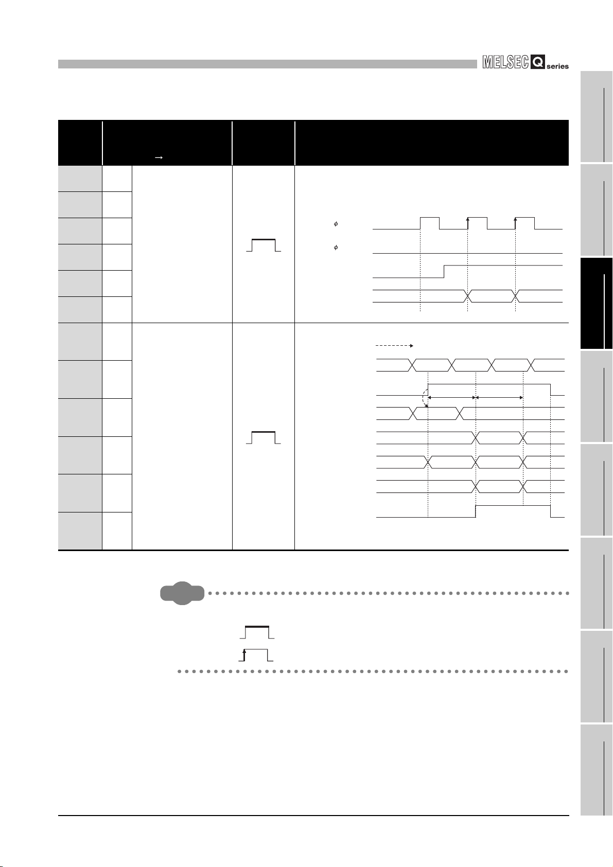
X01 CH1
X06 CH2
X0B CH3
X10 CH4
X15 CH5
X1A CH6
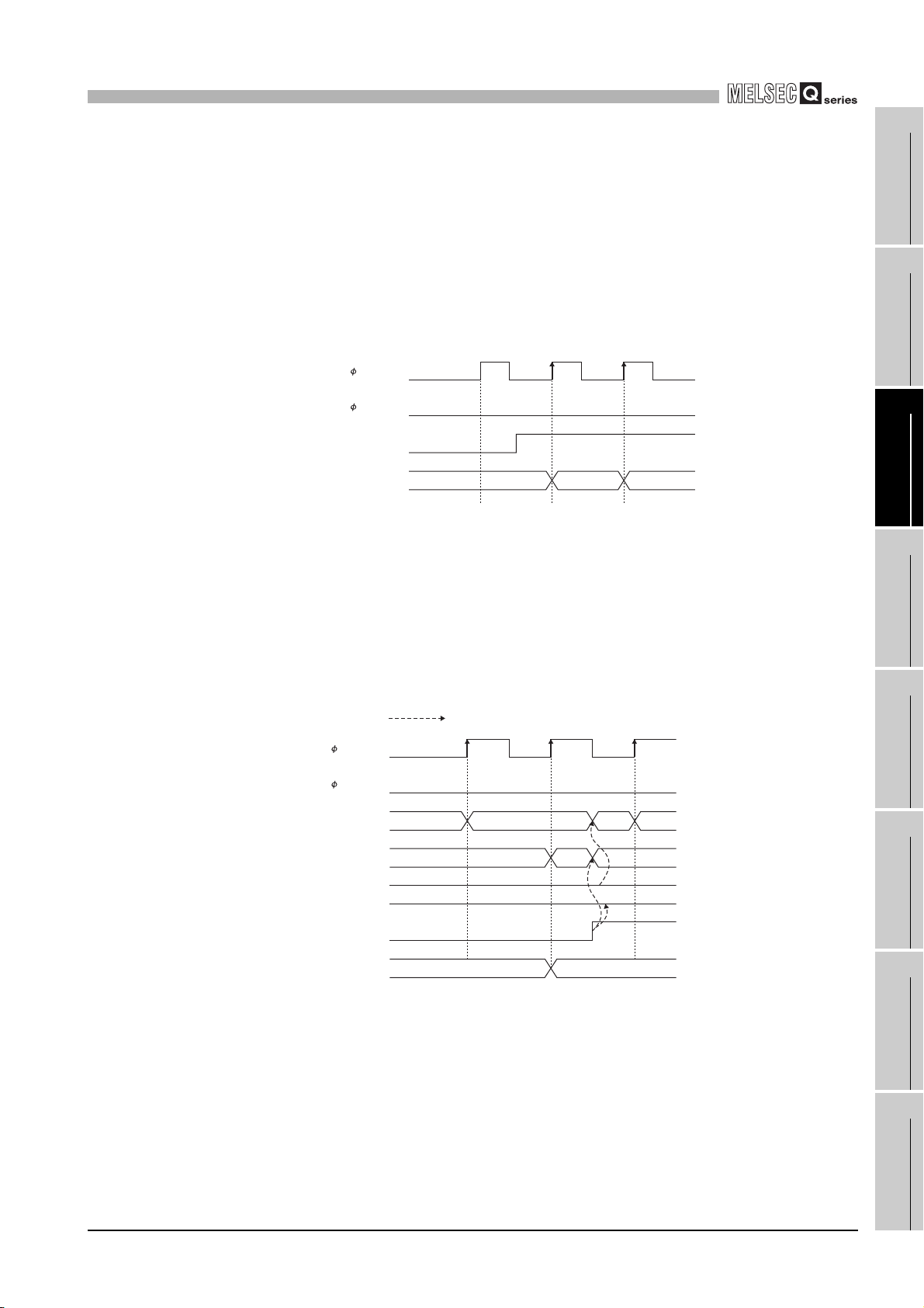
Counter value large
•Turns ON when the present value A (Un\G10 and 11)/present value B (Un\G200 and
201) Coincidence detection point setting (Un\G6 and 7).
•Turns OFF when the present value A (Un\G10 and 11)/present value B (Un\G200 and
201) Coincidence detection point setting (Un\G6 and 7).
•For details of the general operation, refer to Section 5.3.
Immediately after power-ON or reset
of the programmable controller CPU
Coincidence detection
point setting
(Un\G6 and 7)
Present value A
(Un\G10 and 11)
Counter value large
(X01)
Counter value
coincidence
(X02)
Counter value small
(X03)
Coincidence signal
reset command
(Y01)
0
01
ON
OFF
ON
t*
OFF
OFF
ON
OFF
Performed by the QD63P6.
Performed by the sequence program.
100
100 101 1029998
ON
ON
OFF
* t 2ms
ON
OFF
OFF
t*
3 - 5
3.3 I/O Signals to the Programmable Controller CPU
3.3.2 Functions of I/O signals
3
SPECIFICATIONS
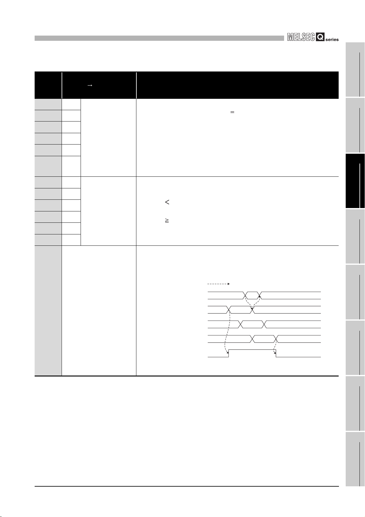
Device
No.
X02 CH1
X07 CH2
X0C CH3
X11 CH4
X16 CH5
X1B CH6
X03 CH1
X08 CH2
X0D CH3
X12 CH4
X17 CH5
X1C CH6
X1F Error occurrence
Signal name
QD63P6 Programmable
controller CPU
Counter value
coincidence
Counter value small
Table 3.5 I/O signals (Continued)
Description
•Turns ON and is the device is latched when the present value A (Un\G10 and 11)/
present value B (Un\G200 and 201) Coincidence detection point setting
(Un\G6 and 7).
•Turns OFF by the coincidence signal reset command (Y01).
•The counter value coincidence (X02) turns ON immediately after power-ON or
reset of the programmable controller CPU, since the present value A (Un\G10
and 11)/present value B (Un\G200 and 201) and coincidence detection point
setting (Un\G6 and 7) are all '0'.
•For general operation, refer to Counter value large (X01) or Section 5.3.
•Turns ON when the present value A (Un\G10 and 11)/present value B (Un\G200
and 201)
•Turns OFF when the present value A (Un\G10 and 11)/present value B (Un\G200
and 201)
•For general operation, refer to Counter value large (X01) or Section 5.3.
•Turns ON when an error occurs at any of arbitrary channels.
•To identify the channel where an error occurs, check the error code of the buffer
memory (Un\G20).
•Turns OFF when all channels are normal.
Coincidence detection point setting (Un\G6 and 7).
Coincidence detection point setting (Un\G6 and 7).
Performed by the QD63P6.
CH1 Error reset command
(Un/G21)
CH1 Error code
(Un/G20)
CH2 Error code
(Un/G50)
010
01000
0*1000
1
OVERVIEW
2
SYSTEM
CONFIGURATION
3
SPECIFICATIONS
4
PROCEDURES AND
SETTINGS BEFORE
OPERATION
5
FUNCTIONS
6
CH3 to 6 Error code
Error occurrence
(X1F)
* Assumed that the errors have been reset with the error reset
command of each channel.
3.3 I/O Signals to the Programmable Controller CPU
ON
OFF
3.3.2 Functions of I/O signals
0*1000
UTILITY PACKAGE
(GX Configurator-CT)
7
PROGRAMMING
8
TROUBLESHOOTING
3 - 6
3
Device
No.
Y01 CH1
Y06 CH2
Y0B CH3
Y10 CH4
Y15 CH5
Y1A CH6
Y02 CH1
Y07 CH2
Y0C CH3
Y11 CH4
Y16 CH5
SPECIFICATIONS
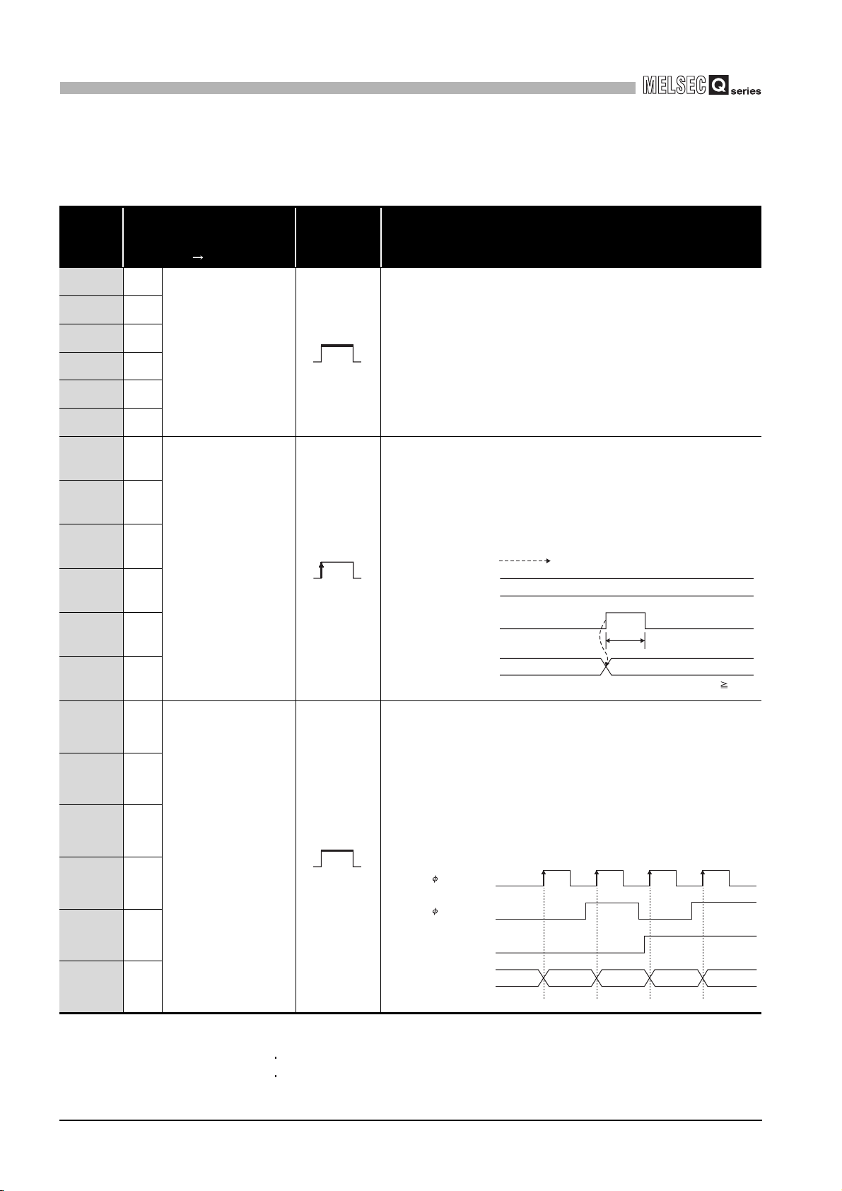
(2) Output signals
Signal name
Programmable controller
CPU QD63P6
Coincidence signal
reset command
Preset command
Table 3.6 Output signals
Operation
timing
•Turn ON to reset the counter value coincidence (X02).
•Note that the ON/OFF time must be 2ms or longer. *1
•Turn OFF the coincidence signal reset command (Y01) when the
•For general operation, refer to Counter value large (X01) or
•Turn ON to execute the preset function.
•Note that the ON/OFF time must be 2ms or longer. *1
•Turn OFF the preset command (Y02) when the preset value
•For general operation, refer to "Section 5.4".
Description
counter value coincidence (X02) is reset.
Section 5.3.
setting (Un\G4 and 5) is stored to the present value A (Un\G10
and 11)/present value B (Un\G200 and 201).
Performed by the QD63P6.
CH1 Preset value setting
(Un/G4 and 5)
CH1 Preset command
(Y02)
ON
100
t*
OFF
Y1B CH6
Y03 CH1
Y08 CH2
Y0D CH3
Y12 CH4
Y17 CH5
Y1C CH6
Subtraction count
command
* 1 Set ON/OFF time such as the coincidence signal reset command (Y01) to 2ms or longer using the
CH1 Present value A
(Un/G10 and 11)
•Turn ON to perform the subtraction count at 1-phase pulse input
mode.
•If either phase B pulse is input or the subtraction count command
(Y03) turns ON, the subtraction count is performed.
•Check that the phase B pulse is input and the subtraction count
command (Y03) is OFF for addition.
•This command operates as follows when the pulse input mode is
1 multiple of 1 phase.
A
B
Subtraction count command
following methods.
Using the timer (T) device
Set the constant scan to 2 ms or longer.
CH1
(Y03)
CH1
Present value A
(Un/G10 and 11)
1000
*: t 2ms
ON ON
OFF
ON
99 98 9710099
3 - 7
3.3 I/O Signals to the Programmable Controller CPU
3.3.2 Functions of I/O signals
3
Device
No.
Y04 CH1
Y09 CH2
SPECIFICATIONS
Signal name
Programmable controller
CPU QD63P6
Table 3.6 Output signals (Continued)
Operation
timing
•Turn ON to perform count operation.
•This command operates as follows when the pulse input mode is
1 multiple of 1 phase.
1
Description
OVERVIEW
2
Y0E CH3
Y13 CH4
Y18 CH5
Y1D CH6
Y05 CH1
Y0A CH2
Y0F CH3
Y14 CH4
Y19 CH5
Y1E CH6
Count enable
command
Periodic pulse counter
start command
A
B
Count enable command
(Y04)
Present value A
(Un\G10 and 11)
ON
Turn ON to execute the periodic pulse counter function.
Performed by the QD63P6.
Present value A
(Un\G10 and 11)
Periodic pulse
counter start command
(Y05)
Period setting
(Un\G9)
Previous periodic pulse
count value
(Un\G14 and 15)
Present periodic pulse
count value
(Un\G16 and 17)
udgment value for updated
periodic pulse count value
(Un\G18 and 19)
Periodic counter flag
(Un\G13)
ON
*
T10
*The period setting (Un\G9) is enabled when the periodic pulse
counter start command (Y05) turns ON from OFF.
2
T1
ON
3410
T1
T2
10
2
10
SYSTEM
CONFIGURATION
3
210
SPECIFICATIONS
4
OFF
2
310
2
OFF
PROCEDURES AND
SETTINGS BEFORE
OPERATION
5
FUNCTIONS
6
Remark
Definitions of the expressions in Operation timing are as follows.
• Enabled while the signal is ON.
• Enabled when the signal turns from OFF to ON.
3.3 I/O Signals to the Programmable Controller CPU
3.3.2 Functions of I/O signals
3 - 8
UTILITY PACKAGE
7
8
(GX Configurator-CT)
PROGRAMMING
TROUBLESHOOTING
3
SPECIFICATIONS
3.4 Buffer Memory Assignment
3.4.1 List of buffer memory assignment
The following table shows the buffer memory assignment of the QD63P6.
Table 3.7 List of buffer memory assignment
Address (decimal notation)
CH1 CH2 CH3 CH4 CH5 CH6
0 30 60 90 120 150
1 31 61 91 121 151 (H)
2 32 62 92 122 152
3 33 63 93 123 153 (H)
4 34 64 94 124 154
5 35 65 95 125 155 (H)
6 36 66 96 126 156
7 37 67 97 127 157 (H)
8 38 68 98 128 158 Coincidence detection point change request
9 39 69 99 129 159 Period setting
10 40 70 100 130 160
11 41 71 101 131 161 (H)
12 42 72 102 132 162 Overflow detection flag
13 43 73 103 133 163 Periodic counter flag
14 44 74 104 134 164
15 45 75 105 135 165 (H)
16 46 76 106 136 166
17 47 77 107 137 167 (H)
18 48 78 108 138 168 Judgment value for updated periodic
19 49 79 109 139 169 (H)
20 50 80 110 140 170 Error code
21 51 81 111 141 171 Error reset command Read/write are enabled.
22 52 82 112 142 172
to to to to to to
29 59 89 119 149 179
200 202 204 206 208 210
201 203 205 207 209 211 (H)
Ring counter lower limit value *2
Ring counter upper limit value *2
Preset value setting *2
Coincidence detection point setting *2
Present value A *2
Previous periodic pulse count value *2
Present periodic pulse count value *2
pulse count value *2
Reserved - -
Present value B *2
* 1 FInitial value which is set when the programmable controller CPU is powered ON or reset.
Setting contents
(L)
(L)
(L)
(L)
(L)
(L)
(L)
(L)
(L)
Initial
value
*1
0
0 Read only
Read/write
Read/write are enabled.
Read only
3 - 9
POINT
• The reserved areas in the above table and areas not mentioned in the
table are for system use, not for users. If written by a user, the functions
of the QD63P6 are not ensured.
• All data in the buffer memory of the QD63P6 are initialized when the
programmable controller CPU is powered ON or reset. To save
necessary data, use the FROM/DFRO/TO/DTO instructions in the
sequence program or make setting with the utility package for writing/
reading the buffer memory data.
3.4 Buffer Memory Assignment
3.4.1 List of buffer memory assignment

3
SPECIFICATIONS
POINT
• Items with "*2" in Table 3.7 are stored in 32-bit signed binary to the buffer
memory; therefore, make sure to read each value in units of 2 words.
• Since the buffer memory contents are automatically updated by count
operation, the latest count value can be read from the buffer memory.
1
OVERVIEW
2
SYSTEM
CONFIGURATION
3
SPECIFICATIONS
4
PROCEDURES AND
SETTINGS BEFORE
OPERATION
5
FUNCTIONS
6
UTILITY PACKAGE
(GX Configurator-CT)
7
PROGRAMMING
8
3.4 Buffer Memory Assignment
3.4.1 List of buffer memory assignment
TROUBLESHOOTING
3 - 10
3
SPECIFICATIONS
3.4.2 Details of the buffer memory
This section describes details of the QD63P6 buffer memory.
Each item contains the I/O numbers (X/Y) and buffer memory addresses of channel 1 only.
For buffer memory addresses of channel 2 or later and I/O numbers (X/Y) of channel 2 or
later, refer to Section 3.4.1 and Section 3.3.1, respectively.
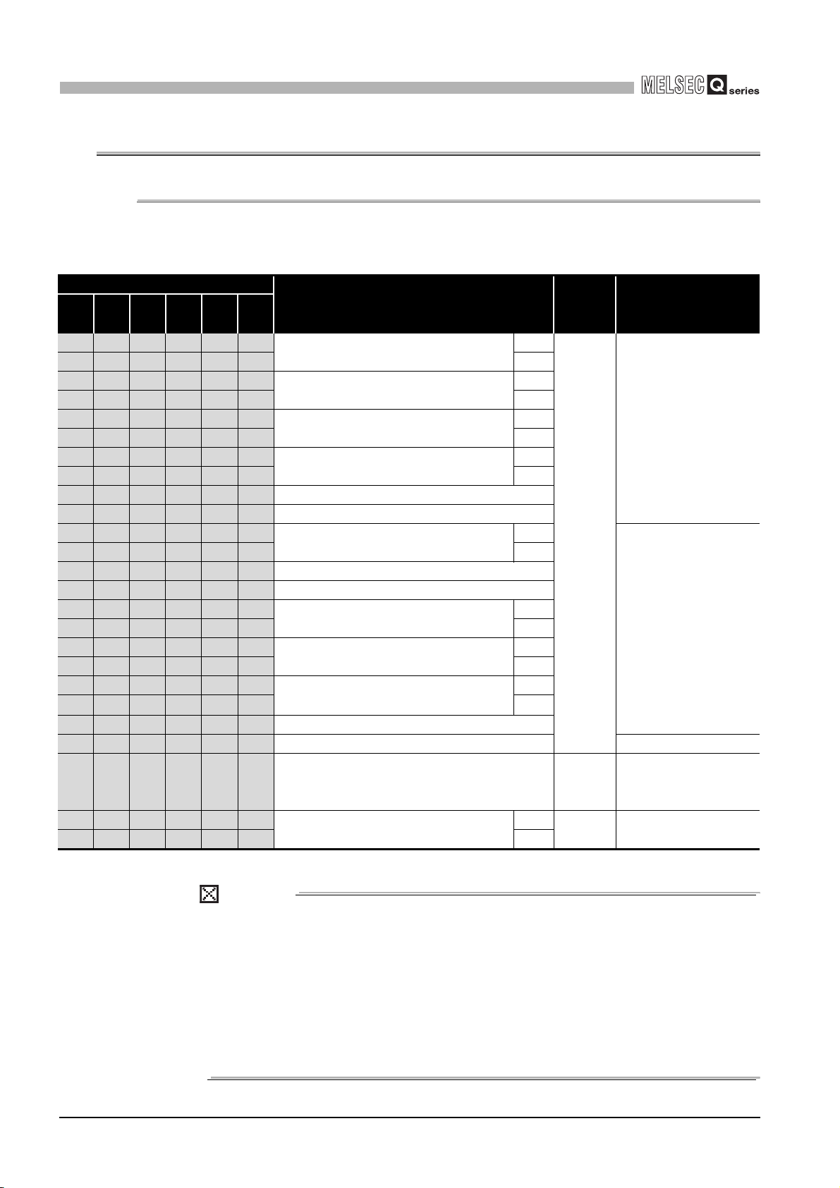
(1) Ring counter lower limit value (Un\G0 and 1)
Ring counter upper limit value (Un\G2 and 3)
• This area is used for setting count range when the counter format is the ring
counter. (Refer to Section 5.2.2.)
• Setting value when the count enable command (Y04) changes from OFF to ON
becomes effective.
• Setting range is from -2147483648 to 2147483647 (32-bit signed binary).
Count enable command
(Y04)
Ring counter lower limit value
(Un\G0 and 1)
Ring counter upper limit value
(Un\G2 and 3)
*1: Value when the count enable command (Y04) changes from OFF
to ON becomes effective.
*2: Does not become effective until the count enable command (Y04)
changes from OFF to ON.
Figure 3.1 Timing chart for the ring counter lower limit value (Un\G0 and 1) and ring counter upper limit value (Un\G2 and 3)
ON
*1
-200-1000
*2
*1
2001000
*2
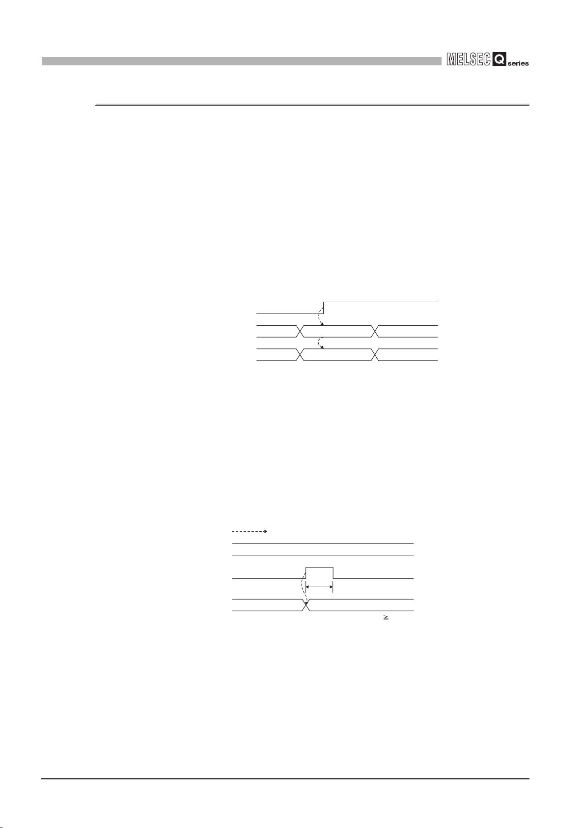
(2) Preset value setting (Un\G4 and 5)
• This area is used for setting the preset value for the counter. (Refer to Section
5.4.)
• Setting value when the preset command (Y02) changes from OFF to ON
becomes effective.
• Setting range is from -2147483648 to 2147483647 (32-bit signed binary).
Performed by the QD63P6.
Preset value setting
(Un\G4 and 5)
Preset command
(Y02)
ON
100
t*
OFF
3 - 11
Present value
(Un\G10 and 11)
Figure 3.2 Timing chart for the preset value setting (Un\G4 and 5)
• For details of the general operation, refer to Section 5.4.
3.4 Buffer Memory Assignment
3.4.2 Details of the buffer memory
1000
* t 2ms
3
SPECIFICATIONS
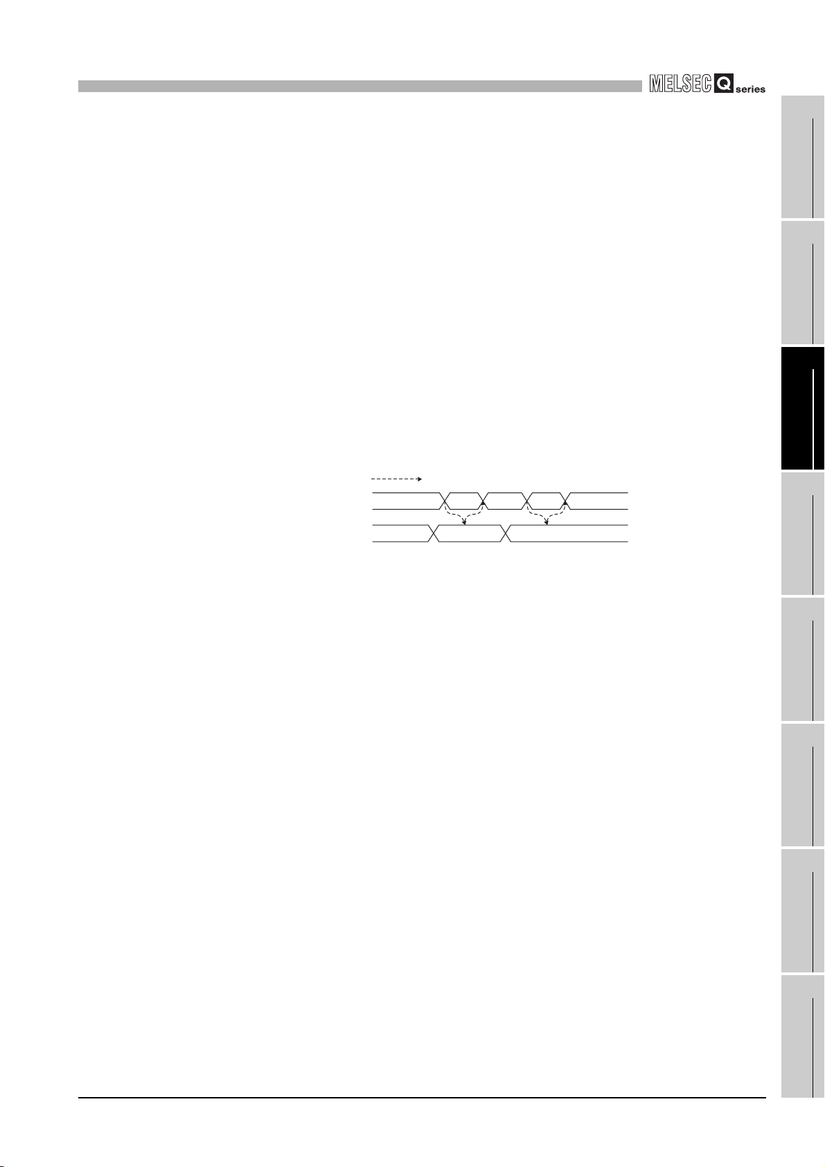
(3) Coincidence detection point setting (Un\G6 and 7)
Coincidence detection point change request (Un\G8)
• Write the coincidence detection point setting value to be compared with the
present value A (Un\G10 and 11)/counter present value B (Un\G200 and 201) for
counter.
• When 1 (Change request) is written to the coincidence detection point change
request (Un\G8), the value written to the coincidence detection point setting
(Un\G6 and 7) becomes effective, the QD63P6 writes 0 (No change request) to
the coincidence detection point change request (Un\G8), and then the
coincidence detection point setting is started.
• Setting range of the coincidence detection point setting (Un\G6 and 7) is from
-2147483648 to 2147483647 (32-bit signed binary).
• If 1 (Change request) is not written into the coincidence detection point change
request (Un\G8), the coincidence detection point setting value (Un\G6 and 7)
does not become effective.
• If 1 (Change request) is not written, the setting is not reflected.
Coincidence detection
point change request
(Un\G8)
Coincidence detection
point setting
(Un\G6 and 7)
Figure 3.3 Timing chart for the coincidence detection point setting (Un/G6 and 7)
and coincidence detection point change request (Un\G8)
Performed by the QD63P6.
1
*1
0
*1 When the coincidence detection point setting (Un\G6 and 7)
becomes effective, the QD63P6 writes 0 to the coincidence
detection point change request (Un\G8).
*1
200100
1
OVERVIEW
2
SYSTEM
CONFIGURATION
3
SPECIFICATIONS
4
0010
PROCEDURES AND
SETTINGS BEFORE
OPERATION
5
• For details of the general operation, refer to Section 5.3.
FUNCTIONS
6
UTILITY PACKAGE
(GX Configurator-CT)
7
PROGRAMMING
8
3.4 Buffer Memory Assignment
3.4.2 Details of the buffer memory
TROUBLESHOOTING
3 - 12

3
SPECIFICATIONS
(4) Period setting (Un\G9)
• This area is used for writing the cycle at which the periodic pulse counter function
(refer to Section 5.5) is to be performed.
• Setting value when the periodic pulse counter start command (Y05) changes
from OFF to ON becomes effective.
• Setting range is from 1 to 65535 (16-bit binary) and unit of the time is 10 [ms].
Example) Writing 420 to the period setting (Un\G9)
420 10 4200 [ms]
Present value A
(Un\G10 and 11)
Periodic pulse
counter start command
(Y05)
Period setting
(Un\G9)
Previous periodic pulse
count value
(Un\G14 and 15)
Present periodic pulse
count value
(Un\G16 and 17)
Judgment value
for updated periodic pulse
count value
(Un\G18 and 19)
Periodic counter flag
(Un\G13)
Figure 3.4 Timing chart for the period setting (Un\G9)
Performed by the QD63P6.
2
ON
*
* Period setting (Un\G9) when the periodic pulse counter start
command (Y05) changes from OFF to ON becomes effective.
T1
T10
ON
3410
T1
T2
10
2
10
OFF
2
310
2
OFF
POINT
• When writing from 32768 to 65535 (8000H to FFFFH) in the period setting
(Un\G9) (refer to (4) in this section), write it in hexadecimal number.
• If 0 is set to the period setting (Un\G9), the period setting error (error
code: 600) is stored to the error code (Un\G20) and the periodic pulse
counter function is not executed.
To execute the periodic pulse counter function, write a value within the
setting range (1 to 65535) to the period setting (Un\G9) and turn the
periodic pulse counter start command (Y05) ON, OFF and ON again.
Note that the OFF time must be 2ms or longer.
3 - 13
3.4 Buffer Memory Assignment
3.4.2 Details of the buffer memory
3
SPECIFICATIONS
(5) Present value A (Un\G10 and 11) and present value B (Un\G200 and 201)
• The present counter value is stored in this area.
• Select the present value A (Un\G10 and 11) to read such as the present value
and overflow detection flag (Un\G12) for each channel, and select the present
value B (Un\G200 and 201) to read the present values of multiple channels at a
time. Set the storage location (present value A/present value B) with the
intelligent function module switch. (Refer to Section 4.5.)
• The range of a value to be read is from -2147483648 to 2147483647 (32-bit
signed binary).
Count enable command
(Y04)
1
OVERVIEW
2
A
B
ON
SYSTEM
CONFIGURATION
3
Present value A
(Un\G10 and 11)
Figure 3.5 Timing chart for the present value A (Un\G10 and 11)
210
(6) Overflow detection flag (Un\G12)
• Overflow occurrence status is stored in this area when the counter format is the
linear counter (refer to Section 5.2.2).
• According to the overflow occurrence status, 0 (No detection) or 1 (Overflow
occurred) is stored to the overflow detection flag (Un\G12).
• This flag operates as follows. (when the pulse input mode is 1 multiple of 1
phase)
Performed by the QD63P6.
A
B
Present value A
(Un\G10 and 11)
Overflow detection flag
(Un\G12)
Preset value setting
(Un\G4 and 5)
Preset command
(Y02)
Error code
(Un\G20)
Figure 3.6 Timing chart for the overflow detection flag (Un\G12)
0
ON
1021474836472147483646
010
1000
SPECIFICATIONS
4
PROCEDURES AND
SETTINGS BEFORE
OPERATION
5
FUNCTIONS
6
UTILITY PACKAGE
(GX Configurator-CT)
7
3.4 Buffer Memory Assignment
3.4.2 Details of the buffer memory
PROGRAMMING
8
TROUBLESHOOTING
3 - 14

3
SPECIFICATIONS
(7) Periodic counter flag (Un\G13)
• Operation status of the function is stored in this area during execution of the
periodic pulse counter function (refer to Section 5.5).
• "0" is stored during stop of the periodic pulse counter function and "1"is stored
during execution of the function in the periodic counter flag (Un\G13).
Present value A
(Un\G10 and 11)
Periodic pulse
counter start command
(Y05)
Period setting
(Un\G9)
Previous periodic pulse
count value
(Un\G14 and 15)
Present periodic pulse
count value
(Un\G16 and 17)
Judgment value
for updated periodic pulse
count value
(Un\G18 and 19)
Periodic counter flag
(Un\G13)
Figure 3.7 Timing chart for the periodic counter flag (Un\G13)
Performed by the QD63P6.
2
ON
*
* Period setting (Un\G9) when the periodic pulse counter start
command (Y05) changes from OFF to ON becomes effective.
T1
T10
ON
3410
T1
T2
10
2
10
OFF
2
310
2
OFF
(8) Previous periodic pulse count value (Un\G14 and 15), present periodic
pulse count value (Un\G16 and 17), and judgment value for updated
periodic pulse count value (Un\G18 and 19)
• This area is used at the periodic pulse counter function (refer to Section 5.5)
execution.
• For general operation, refer to the periodic pulse counter function (Section 5.5).
• After the update of the previous periodic pulse count value (Un\G14 and 15) and
present periodic pulse count value (Un\G16 and 17), the previous periodic pulse
count value (Un\G14 and 15) is stored in the judgment value for updated periodic
pulse count value (Un\G18 and 19).
• If the previous periodic pulse count value (Un\G14 and 15) and judgment value
for updated periodic pulse count value (Un\G18 and 19) are not equal,
inconsistency occurs. Reread the previous periodic pulse count value (Un\G14
and 15), present periodic pulse count value (Un\G16 and 17), and judgment
value for updated periodic pulse count value (Un\G18 and 19).
• The range of a value to be read is from -2147483648 to 2147483647 (32-bit
signed binary).
(9) Error code (Un\G20)
• Code of the detected error (refer to Section 8.5) is stored in this area.
• For operations when multiple errors occur concurrently, refer to POINT in Section
8.5.
3 - 15
3.4 Buffer Memory Assignment
3.4.2 Details of the buffer memory

3
SPECIFICATIONS
(10) Error reset command (Un\G21)
• This area is used for resetting the error code stored in the error code of buffer
memory (Un\G20) by "0".
• Writing 1 (ON) to the error reset command (Un\G21) resets the error code.
• After an error code is reset, the QD63P6 writes 0 (OFF) to the error reset
command (Un\G21).
• After fixing the error cause, make sure to reset the error code with the error reset
command (Un\G21).
If a new error (error code: 100 to 600) occurs while an error code is still stored to
the error code in buffer memory (Un\G20), the error code stored last is retained
and the latest error code is not stored. (Refer to Section 8.5.)
• If the error code is reset with the error reset command (Un\G21) while the error
cause has not yet been fixed, the error code is stored again to the error code in
buffer memory (Un\G20) when the error cause is detected again. (Refer to
Section 8.5.)
• If a value other than 1 (ON) is written to the error reset command (Un\G21), the
error is not reset.
Error reset command
(Un\G21)
Error code
(Un\G20)
Figure 3.8 Timing chart for the error reset command (Un\G21)
Performed by the QD63P6.
2010
*1 *2
100
*1 After an error code is reset, the QD63P6 writes 0 to the error
reset command (Un\G21).
*2 If the error reset command (Un\G21) is other than 1, the
QD63P6 does not reset the error code.
1000
1
OVERVIEW
2
SYSTEM
CONFIGURATION
3
SPECIFICATIONS
4
PROCEDURES AND
SETTINGS BEFORE
OPERATION
5
3.4 Buffer Memory Assignment
3.4.2 Details of the buffer memory
3 - 16
FUNCTIONS
6
UTILITY PACKAGE
(GX Configurator-CT)
7
PROGRAMMING
8
TROUBLESHOOTING

3
SPECIFICATIONS
3.5 Interface with External Devices
The following table shows the list of external device interface for the QD63P6.
Table 3.8 External device interface list for the QD63P6
I/O
classification
Internal circuit
Terminal
number
Phase A pulse input + ON 4.5 to 5.5 V 6.4 to 11.5 mA
Signal name Operation
Input voltage
(guaranteed
value)
Operating
current
(guaranteed
value)
Input
240 1/8 W
240 1/8 W
Signal name
Reserved B20 A20 Reserved
CH1 Phase A pulse input - B19 A19 CH1 Phase A pulse input +
CH1 Phase B pulse input - B18 A18 CH1 Phase B pulse input +
Reserved B17 A17 Reserved
CH2 Phase A pulse input - B16 A16 CH2 Phase A pulse input +
CH2 Phase B pulse input - B15 A15 CH2 Phase B pulse input +
Reserved B14 A14 Reserved
CH3 Phase A pulse input - B13 A13 CH3 Phase A pulse input +
CH3 Phase B pulse input - B12 A12 CH3 Phase B pulse input +
Reserved B11 A11 Reserved
CH4 Phase A pulse input - B10 A10 CH4 Phase A pulse input +
CH4 Phase B pulse input - B09 A09 CH4 Phase B pulse input +
Reserved B08 A08 Reserved
CH5 Phase A pulse input - B07 A07 CH5 Phase A pulse input +
CH5 Phase B pulse input - B06 A06 CH5Phase B pulse input +
Reserved B05 A05 Reserved
CH6 Phase A pulse input - B04 A04 CH6 Phase A pulse input +
CH6 Phase B pulse input - B03 A03 CH6 Phase B pulse input +
Reserved B02 A02 Reserved
Reserved B01 A01 Reserved
Refer to
Table 3.9.
Table 3.9 Terminal layoutof each channel
Phase A pulse input - OFF 2 V or less 0.1 mA or less
Phase B pulse input + ON 4.5 to 5.5 V 6.4 to 11.5 mA
Phase B pulse input - OFF 2 V or less 0.1 mA or less
Terminal
number
Signal name
3 - 17
3.5 Interface with External Devices

3
SPECIFICATIONS
3.6 Connectable Encoders
The encoders connectable to the QD63P6 are described below.
• Open collector output type encoders
• CMOS level voltage output type encoders
(Confirm that the encoder output voltage meets the specifications for the
QD63P6.)
POINT
The following encoder is not applicable for the QD63P6.
• TTL level voltage output type encoders
1
OVERVIEW
2
SYSTEM
CONFIGURATION
3
SPECIFICATIONS
4
PROCEDURES AND
SETTINGS BEFORE
OPERATION
5
FUNCTIONS
6
UTILITY PACKAGE
(GX Configurator-CT)
7
PROGRAMMING
8
3.6 Connectable Encoders
TROUBLESHOOTING
3 - 18

PROCEDURES AND SETTINGS BEFORE
4
OPERATION
CHAPTER4 PROCEDURES AND SETTINGS BEFORE
OPERATION
This chapter describes the operating procedures before operation, part names, settings,
and wiring of the QD63P6.
4.1 Handling Precautions
This section describes precautions on handling the QD63P6.
(1) Do not drop the module case and/or connector or apply a strong impact
to it.
(2) Do not remove the printed-circuit board of the module from the case.
Doing so will cause failure.
(3) Be careful to prevent foreign matter such as wire chips from entering the
module.
Failure to do may cause a fire, failure or malfunction.
(4) A protective film is attached to the module top to prevent foreign matter
such as wire chips from entering the module during wiring.
Do not remove the film during wiring.
Be sure to remove it for heat dissipation before system operation.
(5) Tighten the fixing screws within the following torque ranges.
If the screw is too loose, it may cause a drop, short circuit, or
malfunction.
Excessive tightening may damage the screw and/or the module,
resulting in a drop, short circuit or malfunction.
Table 4.1 Tightening torque range of module fixing screw
Screw Tightening torque range
Module fixing screw (M3)
* 1 The module can be easily mounted to a base unit, using the hook on the upper part of the module.
However, it is recommended to secure it with the module fixing screws when used in an
environment where constant vibrations may occur.
*1
0.36 to 0.48 N·m
4 - 1
(6) To mount the module on the base unit, fully insert the module fixing
projection into the fixing hole in the base unit and press the module
using the hole as a fulcrum.
Incorrect module mounting may cause a malfunction, failure, or drop of
the module.
4.1 Handling Precautions

PROCEDURES AND SETTINGS BEFORE
4
OPERATION
4.2 Procedures before Operation
The following flowchart shows the procedures for operating the QD63P6.
1
Start
Module mounting
Mount the QD63P6 to the specified slot.
Wiring
Wire external devices to the QD63P6.
Intelligent function module switch setting
Set the switches with GX Developer
(refer to Section 4.5).
Use GX Configurator-CT?
No
No
Make the initial setting?
Yes
Initial setting
Create a sequence program for writing
initial values with the FROM/TO
instruction.
Yes
No
Initial setting
Make initial settings with
GX Configurator-CT (refer to Section 6.4).
Make the initial setting?
Yes
OVERVIEW
2
SYSTEM
CONFIGURATION
3
SPECIFICATIONS
4
PROCEDURES AND
SETTINGS BEFORE
OPERATION
5
Programming
Create and a program for counter
processing with the FROM/TO instruction
and check it.
Operation
Figure 4.1 Procedures before operation
No
Make the auto refresh setting?
Yes
Auto refresh setting
Make the auto refresh setting with
GX Configurator-CT (refer to Section 6.5).
Programming
Create and a program for counter
processing without the FROM/TO
instruction and check it.
FUNCTIONS
6
UTILITY PACKAGE
(GX Configurator-CT)
7
PROGRAMMING
8
4.2 Procedures before Operation
TROUBLESHOOTING
4 - 2
PROCEDURES AND SETTINGS BEFORE
)
4
OPERATION
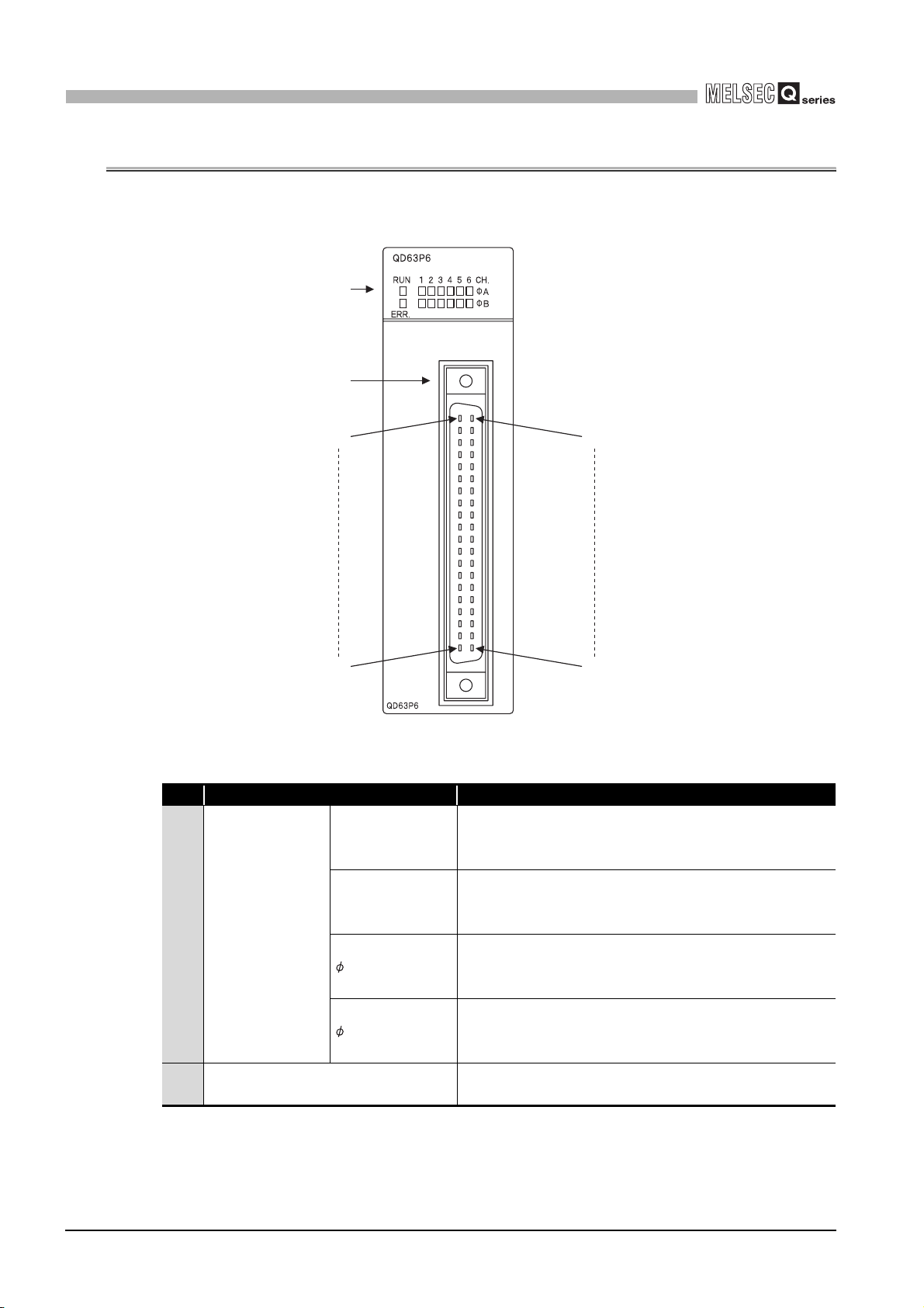
4.3 Part Names
The following explains the part names of the QD63P6.
(Connector terminal number) (Connector terminal number
1)
2)
B20
A20
B01
Figure 4.2 Appearance of the QD63P6
Name Description
RUN
ERR.
1) LED display
A_CH1 to CH6
B_CH1 to CH6
2) External device connector (40 pins)
A01
Table 4.2 Part names
Indicates operation status of the QD63P6.
ON: Normal operation
OFF: Watchdog timer error
Indicates error status of the QD63P6.
ON: Error at 1 or later CH
OFF: All channels in normal operation
Indicates input status of A- phase pulse terminal.
ON: Pulse ON
OFF: Pulse OFF
Indicates input status of B- phase pulse terminal.
ON: Pulse ON
OFF: Pulse OFF
Connector for connecting an encoder
For terminal layout, refer to Section 3.5.
4 - 3
4.3 Part Names

4
PROCEDURES AND SETTINGS BEFORE
OPERATION
(1) Connectors for external wiring
Purchase the connector for the QD63P6 separately.
The following tables show the recommended connector types and crimp tool.
(a) Connector types
Table 4.3 Connector types
Typ e Model
Soldering type, straight out A6CON1
Crimp type, straight out A6CON2
Soldering type, usable for both straight out and
diagonal out
* The A6CON3 connector (pressure welding type, straight out) cannot be used for the QD63P6.
(b) Connector crimp tool
Table 4.4 Connector crimp tool
Type Model Applicable wire size Contact
Crimp tool FCN-363T-T005/H AWG#24 to 28
A6CON4
FUJITSU COMPONENT
LIMITED
1
OVERVIEW
2
SYSTEM
CONFIGURATION
3
SPECIFICATIONS
4
PROCEDURES AND
SETTINGS BEFORE
OPERATION
5
FUNCTIONS
6
UTILITY PACKAGE
(GX Configurator-CT)
7
PROGRAMMING
8
4.3 Part Names
TROUBLESHOOTING
4 - 4

PROCEDURES AND SETTINGS BEFORE
4
OPERATION
4.4 Wiring
4.4.1 Wiring precautions
This section describes wiring an encoder and controller to the QD63P6.
One of the conditions to maximize the QD63P6 functions and make the system highreliable, the external wiring has to be laid so that the QD63P6 becomes less subject to
noise.
This section describes the precautions on external wiring.
(1) Inputting a signal of different voltage may result in a malfunction or
mechanical failure.
(2) For 1-phase input, always perform pulse input wiring on the phase A
side.
(3) When pulse status noise is input, the QD63P6 may miscount.
(4) Take the following measures against noise for high-speed pulse input.
(a) Always use a shielded twisted pair cable and provide grounding.
(b) Wire the shielded twisted pair cables so as not to be in parallel with wires causing
much noise such as power lines or I/O wires while keeping a distance of at least
150 mm (5.91 inch) between such wires. Also install the shielded twisted pair
cables as short as possible.
4 - 5
4.4 Wiring
4.4.1 Wiring precautions

4
PROCEDURES AND SETTINGS BEFORE
OPERATION
(5) The following diagram shows an example of wiring for measures against
noise.
Programmable
controller
Inverter
QD63P6
1
OVERVIEW
2
Terminal
block
Install I/O wires at least
150 mm (5.91 inch)
away from the high
voltage equipment such
as relay and inverter.
(Apply this wiring in a
control panel as well.)
AC
motor
Ground the shielded twisted pair cable on the encoder side (relay box).
(The following connection example is for 5 V sink load.)
Current for encoder
To A
To B
To the QD63P6
Terminal
block
+5V
Avoid using a solenoid valve and inductive load together in the same
metallic pipe. If a sufficient distance cannot be secured with high voltage
cable due to such as duct wiring, use CVVS or other shielded cable for the
high voltage cable.
Relay box
Cart
Encoder
0V
5V
E
Figure 4.3 Example of wiring for measures against noise
A
B
To encoder
E
Connect the shielded cable of the encoder and that of the
shielded twisted pair cable inside the relay box. If the
shielded cable of the encoder is not grounded inside the
encoder, ground it in the relay box as indicated by the
dotted line.
Make the distance between the encoder and relay box as
short as possible.
If the distance is long, a voltage drop may occur. Therefore,
check that the voltages while the encoder is in
operation/stop are within the rated voltage at the terminal
block of the relay box using the measure such as a tester.
If the voltage drop is large, take the measures such as
thickening the wire size or using the 5 VDC encoder of less
current consumption.
SYSTEM
CONFIGURATION
3
SPECIFICATIONS
4
PROCEDURES AND
SETTINGS BEFORE
OPERATION
5
(6) When wiring the QD63P6 and an encoder, separate the power supply
cable and signal line. (Refer to POINT in Section 4.4.2.)
4.4 Wiring
4.4.1 Wiring precautions
4 - 6
FUNCTIONS
6
UTILITY PACKAGE
(GX Configurator-CT)
7
PROGRAMMING
8
TROUBLESHOOTING

4
20cm (7.87inch)
to 30cm (11.81inch)
PROCEDURES AND SETTINGS BEFORE
OPERATION
(7) To conform the wiring to the EMC and Low Voltage Directives, ground
the shielded twisted pair cables to a control panel with the AD75CK
cable clamp (manufactured by Mitsubishi Electric Corporation).
In a control panel
QD63P6
20cm (7.87inch)
20cm (7.87inch)
to 30cm (11.81inch)
to 30cm (11.81inch)
AD75CK
Figure 4.4 AD75CK cable clamp
[Grounding shielded twisted pair cable with the AD75CK]
Shielded twisted pair cable
Shield
Grounding terminal
Grounding terminal fixing screw
(M4 8)
Screw for fixing to control panel
(M4)
Figure 4.5 Grounding shielded twisted pair cable with the AD75CK
Maximum four shielded twisted pair cables whose external dimension is around 7 mm
(0.28 inch) can be grounded with the AD75CK.
(For details, refer to the AD75CK-type Cable Clamping Instruction Manual (IB-
68682).)
4 - 7
4.4 Wiring
4.4.1 Wiring precautions

4
PROCEDURES AND SETTINGS BEFORE
OPERATION
1
4.4.2 Example of wiring the module and an encoder
(1) Example of wiring with an encoder of open collector output type (5 VDC)
Phase A
Phase B
QD63P6
Phase A pulse input +
Phase A pulse input -
240 1/8 W
Phase B pulse input +
Phase B pulse input -
240 1/8 W
External power supply
A19
Shielded
twisted pair cable
Shield
B19
A18
Shielded
twisted pair cable
B18
5 VDC
0 V
Figure 4.6 Example of wiring with an encoder (5 VDC)
Shield
5 V
OUT
E
5 V
OUT
E
5 V
0 V
Encoder
OVERVIEW
2
SYSTEM
CONFIGURATION
3
SPECIFICATIONS
4
PROCEDURES AND
SETTINGS BEFORE
OPERATION
5
4.4 Wiring
4.4.2 Example of wiring the module and an encoder
4 - 8
FUNCTIONS
6
UTILITY PACKAGE
(GX Configurator-CT)
7
PROGRAMMING
8
TROUBLESHOOTING
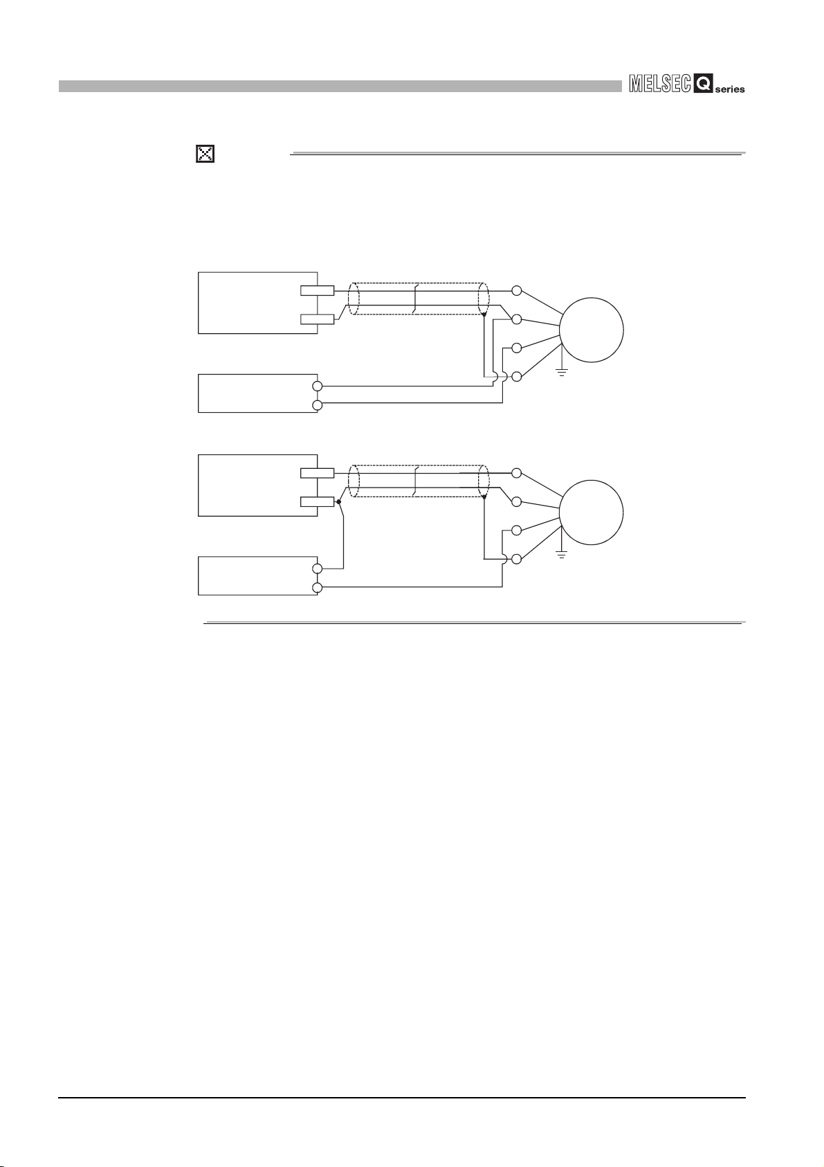
4
PROCEDURES AND SETTINGS BEFORE
OPERATION
POINT
When wiring the QD63P6 and an encoder, separate the power supply cable and
signal line.
The following diagram shows an example of wiring with Phase A. (Wire Phase B
as well).
[Wiring example]
QD63P6
Phase A
External
power supply
[Incorrect wiring example]
QD63P6
Phase A
External
power supply
Pulse
input -
Pulse
input +
5 VDC
0 V
Pulse
input -
Pulse
input +
5 VDC
0 V
Figure 4.8 Incorrect wiring example
Shielded twisted pair cable
Shield
Figure 4.7 Wiring example
Shielded twisted pair cable
Shield
OUT
+5 V
0 V
E
OUT
+5 V
0 V
E
Encoder
Encoder
Since the current
through the shielded
twisted pair cable flows
in the same direction,
canceling effect does
not work, which results
in susceptibility to
electromagnetic
induction.
4 - 9
4.4 Wiring
4.4.2 Example of wiring the module and an encoder
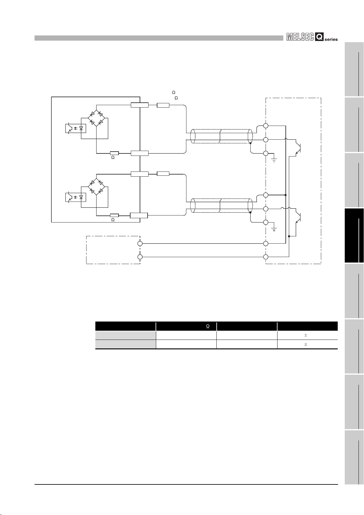
4
PROCEDURES AND SETTINGS BEFORE
OPERATION
(2) Example of wiring with an encoder of open collector output type (12/24
VDC)
Load resistance
QD63P6
Phase A pulse input +
Phase A
Phase A pulse input -
240 1/8 W
Phase B pulse input +
Phase B
Phase B pulse input -
240 1/8 W
12 V 820 1/4 W
24 V 2200 1/2W
A19
Shielded
twisted pair cable
B19
Load resistance
A18
Shielded
twisted pair cable
B18
Shield
Shield
12/24 V
OUT
E
12/24 V
OUT
E
Encoder
1
OVERVIEW
2
SYSTEM
CONFIGURATION
3
SPECIFICATIONS
4
12/24 VDC
External power supply
0 V
Figure 4.9 Example of wiring with an encoder (12/24 VDC)
12/24 V
0 V
According to external power supply voltage, connect load resistance between each pulse
input terminal of the QD63P6 and shielded twisted pair cable. The following table shows
conditions on load resistance.
Table 4.5 Conditions on load resistance
External voltage [V]
12 820 1/4
24 2200 1/2
Load resistance [ ]
Capacity [W] Tol e r a nce [%]
5
5
PROCEDURES AND
SETTINGS BEFORE
OPERATION
5
FUNCTIONS
6
UTILITY PACKAGE
(GX Configurator-CT)
7
4.4 Wiring
4.4.2 Example of wiring the module and an encoder
PROGRAMMING
8
TROUBLESHOOTING
4 - 10

4
PROCEDURES AND SETTINGS BEFORE
OPERATION
POINT
When wiring the QD63P6 and an encoder, separate the power supply cable and
signal line.
The following diagram shows an example of wiring with Phase A. (Wire Phase B
as well).
[Wiring example]
QD63P6
Phase A
External
power supply
Pulse
input -
Pulse
input +
12/24 VDC
0 V
[Incorrect wiring example]
QD63P6
Phase A
External
power supply
Pulse
input -
Pulse
input +
12/24 VDC
0 V
Figure 4.11 Incorrect wiring example
Shielded twisted pair cable
Shield
Figure 4.10 Wiring example
Shielded twisted pair cable
Shield
OUT
+12/24 V
0 V
E
OUT
+12/24 V
0 V
E
Encoder
Encoder
Since the current
through the shielded
twisted pair cable flows
in the same direction,
canceling effect does
not work, which results
in susceptibility to
electromagnetic
induction.
4 - 11
4.4 Wiring
4.4.2 Example of wiring the module and an encoder
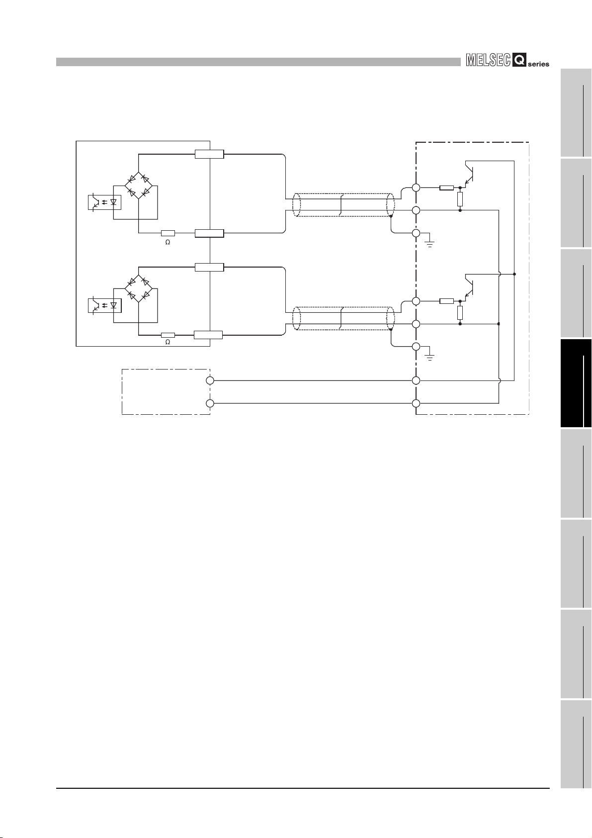
4
PROCEDURES AND SETTINGS BEFORE
OPERATION
1
(3) Example of wiring with an encoder of voltage output type (5 VDC)
Phase A
Phase B
QD63P6
Phase A pulse input +
Phase A pulse input -
240 1/8 W
Phase B pulse input +
Phase B pulse input -
240 1/8 W
5 VDC
External power supply
0 V
A19
Shielded
twisted pair cable
Shield
B19
A18
Shielded
twisted pair cable
B18
Figure 4.12 Example of wiring with an encoder (5 VDC)
Shield
OUT
GND
E
OUT
GND
E
5 V
0 V
Encoder
OVERVIEW
2
SYSTEM
CONFIGURATION
3
SPECIFICATIONS
4
PROCEDURES AND
SETTINGS BEFORE
OPERATION
5
4.4 Wiring
4.4.2 Example of wiring the module and an encoder
4 - 12
FUNCTIONS
6
UTILITY PACKAGE
(GX Configurator-CT)
7
PROGRAMMING
8
TROUBLESHOOTING
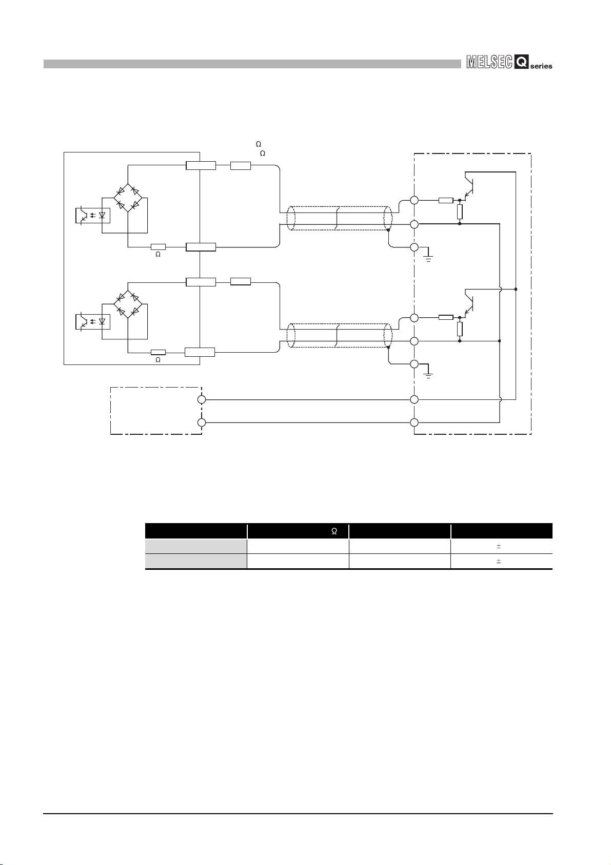
4
PROCEDURES AND SETTINGS BEFORE
OPERATION
(4) Example of wiring with an encoder of voltage output type (12/24 VDC)
Load resistance
QD63P6
Phase A pulse input +
Phase A
Phase A pulse input -
240 1/8 W
12 V 820 1/4 W
24 V 2200 1/2W
A19
Shielded
twisted pair cable
B19
Shield
Encoder
OUT
GND
E
Phase B
Phase B pulse input +
Phase B pulse input -
240 1/8 W
12/24 VDC
External power supply
0 V
Figure 4.13 Example of wiring with an encoder (12/24 VDC)
A18
B18
Load resistance
Shielded
twisted pair cable
Shield
OUT
GND
E
12/24 V
0 V
According to external power supply voltage, connect load resistance between each pulse
input terminal of the QD63P6 and shielded twisted pair cable. The following table shows
conditions on load resistance.
Table 4.6 Conditions on load resistance
External voltage [V]
12 820 1/4
24 2200 1/2
Load resistance [ ]
Capacity [W] Tole r a n ce [%]
5
5
4 - 13
4.4 Wiring
4.4.2 Example of wiring the module and an encoder

PROCEDURES AND SETTINGS BEFORE
4
OPERATION
4.5 Intelligent Function Module Switch Setting
This section describes the intelligent function module switch setting.
The switch setting is made on the [I/O assignment] screen of GX Developer.
(1) Intelligent function module switch setting
The switch has five switches and is set at 16-bit data.
When the switch setting is not made, the default values of the switches from 1 to 5 are
0.
Table 4.7 Intelligent function module switches
Setting item Setting value Default value
Pulse input mode
Switch 1
CH4 CH3 CH2 CH1
Pulse input mode
Switch 2
Switch 3
Switch 4
Switch 5 Reserved: Fixed to 0.
00
Reserved:
Fixed to 0
Counting speed setting
CH6 CH5
0
Reserved: Fixed to 0
Counter format, present value
selection setting
0
Reserved: Fixed to 0
H
H
H
Pulse input mode (Refer to Section 5.1.1.)
0H: 1 multiple of 1 phase
H
1
H: 2 multiples of 1 phase
2
H: CW/CCW
3H: 1 multiple of 2 phases
4
H: 2 multiples of 2 phases
5
H: 4 multiples of 2 phases
Counting speed setting (Refer to Section 3.1.)
Set the following bit pattern with hexadecimal.
b11 b8 b7 b0
00: 10 kPPS
01: 100 kPPS
10: 200 kPPS
Example) CH1 and 2: 200 kPPS, CH3: 100 kPPS, and
CH4 to 6 : 10 kPPS
00 00 00 01 10 10 001A
Counter format (Refer to Section 5.2.1 and Section
5.2.2.)
Set the following bit pattern with hexadecimal.
b7 b0
00
0: Linear counter
1: Ring counter
Example) Linear counter: CH1, CH2, and CH5
Ring counter: CH3, CH4, and CH6
00101100 2C
Present value selection setting (Refer to Section 3.4.2
(5).)
0: Present value A (Un\G10 and 11)
1: Present value B (Un\G200 and 201)
CH CH CH CH CH CH
654321
H
H
1
OVERVIEW
2
SYSTEM
CONFIGURATION
3
0000
H
SPECIFICATIONS
0000
H
CH1CH2CH3CH4CH5CH6
4
PROCEDURES AND
SETTINGS BEFORE
OPERATION
5
0000H
FUNCTIONS
6
UTILITY PACKAGE
(GX Configurator-CT)
7
0000
H
PROGRAMMING
8
4.5 Intelligent Function Module Switch Setting
TROUBLESHOOTING
4 - 14

4
PROCEDURES AND SETTINGS BEFORE
OPERATION
(Example) Target channel: channel 1, pulse input mode setting: 1 multiple of 2
phases, counting speed setting: 200 kPPS, counter format: ring counter, and present
value selection setting: setting value B
Set the switch 1 0003
Set the switch 3 0002
Set the switch 4 0101
H.
H.
H.
POINT
The reserved bits in Table 4.7 are for system use, not for users.
Therefore, always fix them to 0. If used (changed from 0 to 1) by a user, the
operations of the QD63P6 are not ensured.
(2) Details of the intelligent function module switch setting
Table 4.8 Details of the intelligent function module switch setting
Setting item Description Reference
Set the pulse input mode for each channel.
Pulse input mode
Counting speed setting
Counter format Set the counter format for each channel.
Present value selection
setting
When setting 6H to FH, a switch setting error (error code:
810) occurs. (Refer to Section 8.5.)
Set the counting speed for each channel.
(When setting 11 (3H), a switch setting error (error code:
810) occurs. (Refer to Section 8.5.)
Set the same storage location of the present counter
value (present value A (Un\G10 and 11)/present value B
(Un\G200 and 201)) to all channels.
Section 5.1.1
Section 3.1
Section 5.2.1
Section 5.2.2
Section 3.4.2
(5)
4 - 15
4.5 Intelligent Function Module Switch Setting

4
PROCEDURES AND SETTINGS BEFORE
OPERATION
1
(3) Operating procedure
Set the switches on the [I/O assignment] screen of GX Developer.
(a) [I/O assignment] screen
Make the following settings to the slot to which the QD63P6 is mounted.
[Type]: Select [Intelli].
[Model name]: Input the model of the module.
[Points]: Select [32points].
[Start XY]: Input the head I/O number of the QD63P6.
Figure 4.14 Setting example of [I/O assignment]
(b) [Switch setting for I/O and intelligent function module] screen
Click the on the [I/O assignment] screen to display the screen below
and set the switches from 1 to 5.
Entering the values in hexadecimal make the setting easier.
Change [Input format] to [HEX.] and enter values.
OVERVIEW
2
SYSTEM
CONFIGURATION
3
SPECIFICATIONS
4
PROCEDURES AND
SETTINGS BEFORE
OPERATION
5
FUNCTIONS
6
Figure 4.15 [Switch setting for I/O and intelligent function module] screen
POINT
Since [Error time output mode] and [H/W error time PLC operation mode] on the
[Switch setting for I/O and intelligent function module] screen are disabled to the
QD63P6, the settings are unnecessary.
4.5 Intelligent Function Module Switch Setting
4 - 16
UTILITY PACKAGE
7
8
(GX Configurator-CT)
PROGRAMMING
TROUBLESHOOTING

5
FUNCTIONS
CHAPTER5 FUNCTIONS
This chapter describes functions of the QD63P6.
5.1 Pulse Input and Count Methods
5.1.1 Types of the pulse input method
There are six kinds of the pulse input methods: 1 phase pulse input (1 or 2 multiples), CW/
CCW pulse input, and 2 phases pulse input (1, 2 or 4 multiples). The pulse input methods
and count timing are shown in Table 5.1.
This chapter describes I/O numbers (X/Y) of channel 1 only.
For I/O numbers of channels 2 to 6 (X/Y), refer to Section 3.3.1.
The count method is set in the intelligent function module switch setting of GX Developer.
(Refer to Section 4.5.)
Pulse input
method
1 multiple of 1 phase
2 multiples of 1
phase
CW/CCW
For addition count
For subtraction
count
For addition count
For subtraction
count
For addition count
For subtraction
count
Table 5.1 Types of the pulse input method
Count timing
A
B
(and subtraction count
command (Y03))
A
B
(or subtraction count
command (Y03))
A
B
(and subtraction count
command (Y03))
A
B
(or subtraction count
command (Y03))
A
B
A
B
Counts on the rising edge ( ) of A.
B and the subtraction count command (Y03) are OFF.
Counts on the falling edge ( ) of A.
B or the subtraction count command (Y03) is ON.
Counts on the rising ( ) and falling ( ) edges of A.
B and the subtraction count command (Y03) are OFF.
Counts on the rising ( ) and falling ( ) edges of A.
B or the subtraction count command (Y03) is ON.
Counts on the rising edge ( ) of A.
B is OFF.
A is OFF.
Counts on the rising edge ( ) of B.
1 multiple of 2
phases
5 - 1
For addition count
For subtraction
count
A
B
A
B
5.1 Pulse Input and Count Methods
5.1.1 Types of the pulse input method
When B is OFF, counts on the rising edge ( ) of A.
When B is OFF, counts on the falling edge ( ) of A.

5
FUNCTIONS
Pulse input
method
2 multiples of 2
phases
4 multiples of 2
phases
For addition count
For subtraction
count
For addition count
For subtraction
count
Table 5.1 Types of the pulse input method (Continued)
Count timing
A
B
A
B
A
B
A
B
When B is OFF, counts on the rising edge ( ) of A.
When B is ON, counts on the falling edge ( ) of A.
When B is ON, counts on the rising edge ( ) of A.
When B is OFF, counts on the falling edge ( ) of A.
When B is OFF, counts on the rising edge ( ) of A.
When B is ON, counts on the falling edge ( ) of A.
When A is ON, counts on the rising edge ( ) of B.
When A is OFF, counts on the falling edge ( ) of B.
When B is ON, counts on the rising edge ( ) of A.
When B is OFF, counts on the falling edge ( ) of A.
When A is OFF, counts on the rising edge ( ) of B.
When A is ON, counts on the falling edge ( ) of B.
1
OVERVIEW
2
SYSTEM
CONFIGURATION
3
SPECIFICATIONS
4
POINT
In the case of addition in 1-phase pulse input, make sure that phase B pulse input
and the subtraction count command (Y03) are OFF before performing pulse input
of phase A.
If either of phase B pulse input or the subtraction count command (Y03) is ON,
subtraction count is performed in pulse input of phase A.
PROCEDURES AND
SETTINGS BEFORE
OPERATION
5
FUNCTIONS
6
UTILITY PACKAGE
(GX Configurator-CT)
7
5.1 Pulse Input and Count Methods
5.1.1 Types of the pulse input method
PROGRAMMING
8
TROUBLESHOOTING
5 - 2

5
FUNCTIONS
5.2 Selecting Counter Format
By selecting a counter format, the following counter operations are available.
(1) Linear counter
The linear counter generates an overflow error when the count value exceeds the
count range of the QD63P6.
(2) Ring counter
(a) Counting is repeated within the range between the arbitrarily-set ring counter
upper limit value (Un\G2 and 3) and ring counter lower limit value (Un\G0 and 1).
(b) When the same value is set to the ring counter upper limit value (Un\G2 and 3)
and ring counter lower limit value (Un\G0 and 1), counting is repeated in the entire
range of the QD63P6.
Select the linear counter or ring counter in the intelligent function module switch setting of
GX Developer.
For setting details, refer to Section 4.5.
5 - 3
5.2 Selecting Counter Format

5
FUNCTIONS
5.2.1 Selecting the linear counter
(1) Linear counter operation
When the linear counter is selected, counting is operated in a range between 2147483648 (lower limit value) and 2147483647 (upper limit value).
This can be used in combination with the preset function and the coincidence
detection function.
1
OVERVIEW
2
Present counter value
0
Subtraction
Overflow
Figure 5.1 Operation image of the linear counter
Overflow
+2147483647
Addition
-2147483648
(2) Overflow error
(a) When the linear counter is selected for the counter format, if the present value A
(Un\G10 and 11)/present value B (Un\G200 and 201) falls below -2147483648
(lower limit value) in subtraction or exceeds 2147483647 (upper limit value) in
addition, an overflow error (error code: 100) will occur.
(b) If an overflow error occurs, 1 is stored in the overflow detection flag (Un\G12) and
the overflow error (error code: 100) is stored in the error code (Un\G20) in the
buffer memory, and counting is stopped. Even if a pulse is input in that condition,
the present value does not change from -2147483648 or 2147483647.
(c) An overflow error is cancelled by the preset function.
Executing preset stores 0 in the overflow detection flag (Un\G12) in the buffer
memory, allowing restart of counting. Note that, since data in the error code
(Un\G20) are retained until the error is reset, set 1 (ON) in the error reset
command (Un\G21) to reset the error.
SYSTEM
CONFIGURATION
3
SPECIFICATIONS
4
PROCEDURES AND
SETTINGS BEFORE
OPERATION
5
FUNCTIONS
6
(d) When system monitoring is performed during overflow error occurrence by
clicking [Diagnostics] - [System monitor] in GX Developer, a module error can be
identified.
5.2 Selecting Counter Format
5.2.1 Selecting the linear counter
5 - 4
UTILITY PACKAGE
7
8
(GX Configurator-CT)
PROGRAMMING
TROUBLESHOOTING

5
)
FUNCTIONS
5.2.2 Selecting the ring counter
(1) Ring counter operation
When the ring counter is selected, counting is repeated within the range between the
ring counter lower limit value (Un\G0 and 1) and ring counter upper limit value (Un\G2
and 3), which are arbitrarily set in the buffer memory.
No overflow error will occur when the ring counter is selected.
This can be used in combination with the preset function and the coincidence
detection function.
Present counter value
0
Subtraction
+2147483647
Ring counter upper limit value (Un\G2 and 3
Addition
Ring counter lower limit value (Un\G0 and 1)
-2147483648
Figure 5.2 Operation image of the ring counter
(2) Count range of the ring counter
The count range varies depending on the present value A (Un\G10 and 11)/present
value B (Un\G200 and 201), and the ring counter lower limit value (Un\G0 and 1) and
upper limit value (Un\G2 and 3) at the time point of any of the following:
• Count enable command (Y04) changes from OFF to ON.
• Preset is executed.
POINT
• Set appropriate ring counter lower limit value (Un\G0 and 1)/upper limit
value (Un\G2 and 3) so that the following condition is satisfied.
"Ring counter lower limit value Ring counter upper limit value"
(Un\G0 and 1) (Un\G2 and 3)
If the count enable command (Y04) is turned from OFF to ON with this
condition not satisfied, a ring counter upper/lower limit value setting error
(error code: 500) is stored in the error code (Un\G20), and counting does
not start.
• To start the counting after occurrence of the ring counter upper/lower limit
value setting error (error code: 500), set the ring counter lower limit value
(Un\G0 and 1)/upper limit value (Un\G2 and 3) so that the following
condition is satisfied, and turn the counter enable command (Y04) ON,
OFF and ON again.
5 - 5
"Ring counter lower limit value Ring counter upper limit value"
(Un\G0 and 1)(Un\G2 and 3)
Note that the OFF time must be 2ms or longer.
5.2 Selecting Counter Format
5.2.2 Selecting the ring counter

5
)
FUNCTIONS
(a) When using within the specified range
1) Normally the following range is applied.
"Ring counter lower limit
value
(
Un\G0 and 1)(Un\G10 and 11)/
a) General operation
Present counter value
0
Subtraction
Figure 5.3 Ring counter operation image 1
b) Setting method
• Set the ring counter upper limit value (Un\G2 and 3), ring counter lower
limit value (Un\G0 and 1) and preset value setting (Un\G4 and 5) as
shown below, and then turn ON the preset command (Y02).
• After the preset value setting (Un\G4 and 5) became effective, turn OFF
the preset command (Y02) and turn ON the count enable command (Y04).
"
Ring counter lower limit
value
Present value A/
present value B
(
Un\G200 and 201)
+2147483647
Ring counter upper limit value (Un\G2 and 3
Addition
Ring counter lower limit value (Un\G0 and 1)
-2147483648
Preset value setting
Ring counter upper limit
value
Un\G2 and 3)
(
Ring counter upper limit
value
(Un\G0 and 1)(Un\G4 and 5)(Un\G2 and 3)
1
"
OVERVIEW
2
SYSTEM
CONFIGURATION
3
SPECIFICATIONS
4
PROCEDURES AND
SETTINGS BEFORE
"
OPERATION
5
c) Count operation
• Addition count
When the present value A
and 201
ring counter lower limit value
present value A
• Subtraction count
Even if the present value A
and 201
counter lower limit value
subtraction pulse, "Ring counter upper limit value (Un\G2 and 3) -1" is
stored in the present value A
and 201
In both cases of addition and subtraction counts, the ring counter upper limit value
) reaches the ring counter upper limit value (Un\G2 and 3), the
(Un\G10 and 11)/present value B (Un\G200 and 201).
) reaches the ring counter lower limit value (Un\G0 and 1), the ring
).
(Un\G10 and 11)/present value B (Un\G200
(Un\G0 and 1) is automatically stored in the
(Un\G10 and 11)/present value B (Un\G200
(Un\G0 and 1) is held as it is. And by the next
(Un\G10 and 11)/present value B (Un\G200
(Un\G2 and 3) is not stored in the present value A (Un\G10 and 11)/present value
B
(Un\G200 and 201) .
However, the operation is the same as for the case of counting from the ring
counter lower limit value (Un\G0 and 1) if the addition/subtraction count is
performed when the count enable command (Y04) status changes from OFF to
ON or the preset command (Y02) is executed while "Present value A (Un\G10 and
11)/present value B (Un\G200 and 201) Ring counter upper limit value (Un\G2
and 3) is satisfied.
5.2 Selecting Counter Format
5.2.2 Selecting the ring counter
5 - 6
FUNCTIONS
6
UTILITY PACKAGE
(GX Configurator-CT)
7
PROGRAMMING
8
TROUBLESHOOTING

5
FUNCTIONS
d) Setting example
When the count is enabled with a ring counter lower limit value (Un\G0 and
1
) of 0, ring counter upper limit value (Un\G2 and 3) of 2000, and present
value A
(Un\G10 and 11)/present value B (Un\G200 and 201) of 500
Present counter value
1000
0
Subtraction
(2000)
1998 1999 0 1 2
2000 of ring counter upper limit value (Un\G2 and 3) is
not stored in present value A (Un\G10 and 11)/present
value B (Un\G200 and 201).
Figure 5.4 Ring counter operation example 1
Addition
Ring counter upper limit value
Ring counter lower limit value
+2147483647
Ring counter upper
limit value (2000)
Ring counter lower
limit value (0)
-2147483648
5 - 7
5.2 Selecting Counter Format
5.2.2 Selecting the ring counter

5
FUNCTIONS
2) When the following range is applied, the operation is as shown in Figure 5.5.
"Present value A/present value B Ring counter lower limit value"
(Un\G10 and 11)/
(Un\G200 and 201)
or,
"Ring counter upper limit value Present value A/present value B"
(Un\G2 and 3) (Un\G10 and 11)/(Un\G200 and
a) General operation
Present counter value
Subtraction
0
Addition
(Un\G0 and 1)
201)
+2147483647
Ring counter upper limit value (Un\G2 and 3)
Ring counter lower limit value (Un\G0 and 1)
1
OVERVIEW
2
SYSTEM
CONFIGURATION
3
-2147483648
Figure 5.5 Ring counter operation image 2
b) Setting method
• Set the ring counter upper limit value (Un\G2 and 3), ring counter lower
limit value (Un\G0 and 1) and preset value setting (Un\G4 and 5) as
shown below, and then turn ON the preset command (Y02).
• After the preset value setting (Un\G4 and 5) became effective, turn OFF
the preset command (Y02) and turn ON the count enable command (Y04).
"Preset value setting Ring counter lower limit value"
(Un\G4 and 5) (Un\G0 and 1)
or,
"Ring counter upper limit value Preset value setting"
(Un\G2 and 3) (Un\G4 and 5)
SPECIFICATIONS
4
PROCEDURES AND
SETTINGS BEFORE
OPERATION
5
FUNCTIONS
6
UTILITY PACKAGE
(GX Configurator-CT)
7
5.2 Selecting Counter Format
5.2.2 Selecting the ring counter
PROGRAMMING
8
TROUBLESHOOTING
5 - 8

5
FUNCTIONS
c) Count operation
• Addition count
Even if the present value A
and 201
) reaches the ring counter lower limit value (Un\G0 and 1), the ring
counter lower limit value
(Un\G10 and 11)/present value B (Un\G200
(Un\G0 and 1) is held as it is. And by the next
addition pulse, "Ring counter upper limit value (Un\G2 and 3) +1" is stored
in the present value A
201
).
(Un\G10 and 11)/present value B (Un\G200 and
• Subtraction count
When the present value A
and 201
) reaches the ring counter upper limit value (Un\G2 and 3), the
ring counter lower limit value
present value A
(Un\G10 and 11)/present value B (Un\G200 and 201).
(Un\G10 and 11)/present value B (Un\G200
(Un\G0 and 1) is automatically stored in the
In both cases of addition and subtraction counts, the ring counter upper limit
(Un\G2 and 3) is not stored in the present value A (Un\G10 and 11)/
value
present value B
(Un\G200 and 201).
Subtraction
d) Setting example
When the count is enabled with a ring counter lower limit value (Un\G0 and
1
) of 0, ring counter upper limit value (Un\G2 and 3) of 2000, and present
value A
Present counter value
3000
-2147483648
2147483647
(Un\G10 and 11)/present value B (Un\G200 and 201) of 3000
0
Addition
-21474836462147483646
-2147483647
+2147483647
Ring counter upper
limit value (2000)
Ring counter lower
limit value (0)
-2147483648
Ring counter upper
limit value
(2000)
1998 1999 0 1 2
2000 of ring counter upper limit value (Un\G2 and 3)
is not stored in present value A (Un\G10 and
11)/present value B (Un\G200 and 201).
5 - 9
5.2 Selecting Counter Format
5.2.2 Selecting the ring counter
Ring counter lower
limit value
(2000)
1998 1999 0 1 2
2000 of ring counter upper limit value (Un\G2 and 3)
is not stored in present value A (Un\G10 and
11)/present value B (Un\G200 and 201).
Figure 5.6 Ring counter operation example 2
Ring counter upper
limit value
Ring counter lower
limit value

5
FUNCTIONS
(b) When using in the entire range
a) General operation
By setting the same value in the ring counter upper limit value (Un\G2 and 3) and
ring counter lower limit value (Un\G0 and 1), the count operation is repeated in the
entire range of the QD63P6 (from -2147483648 (lower limit value) to 2147483647
(upper limit value)).
Although it operates like the linear counter, no overflow error will occur even if the
present value A (Un\G10 and 11)/present value B (Un\G200 and 201) reaches the
counting range of the QD63P6.
1
OVERVIEW
2
Present counter value
+2147483647
Ring counter lower limit value (Un\G0 and 1)
0
Subtraction
Figure 5.7 Ring counter operation image 3
b) Setting method
• Set any value in the preset value setting (Un\G4 and 5), set the ring counter
upper limit value (Un\G2 and 3) and ring counter lower limit value (Un\G0 and
1) as shown below, and then turn ON the preset command (Y02).
• After the preset value setting (Un\G4 and 5) became effective, turn OFF the
preset command (Y02) and turn ON the count enable command (Y04).
= Ring counter upper limit value (Un\G2 and 3)
Addition
-2147483648
"Ring counter lower limit value = Ring counter upper limit value"
(Un\G0 and 1) (Un\G2 and 3)
c) Count operation
When the following setting is made, regardless of the present value A
and 11
)/present value B (Un\G200 and 201), the count range is the entire
range of signed 32-bit binary numbers (-2147483648 to 2147483647).
(Un\G10
"Ring counter lower limit value = Ring counter upper limit value"
(Un\G0 and 1) (Un\G2 and 3)
SYSTEM
CONFIGURATION
3
SPECIFICATIONS
4
PROCEDURES AND
SETTINGS BEFORE
OPERATION
5
FUNCTIONS
6
d) Setting example
When the count is enabled with a ring counter lower limit value (Un\G0 and 1)
of 1000, ring counter upper limit value
value A
count is operated in the entire range of the QD63P6 (-2147483648 (lower limit
value) to 2147483647 (upper limit value)).
(Un\G10 and 11)/present value B (Un\G200 and 201) of 3000, the
(Un\G2 and 3) of 1000, and present
5.2 Selecting Counter Format
5.2.2 Selecting the ring counter
5 - 10
UTILITY PACKAGE
7
8
(GX Configurator-CT)
PROGRAMMING
TROUBLESHOOTING

5
FUNCTIONS
POINT
(1) When changing the ring counter upper/lower limit value, perform the following:
• Turn OFF the count enable command (Y04) for 2ms or longer.
• Change the setting of the ring counter upper limit value (Un\G2 and 3)
and/or ring counter lower limit value (Un\G0 and 1).
• Turn ON the count enable command (Y04) again.
While the count enable command (Y04) is ON, writing a setting value into the ring
counter upper/lower limit value area (Un\G0 to 3) only stores it in the buffer
memory and is not reflected to the QD63P6. Therefore, the QD63P6 operates
based on the setting before the writing.
If a value was written to the ring counter lower limit value (Un\G2 and 3) or ring
counter upper limit value (Un\G0 and 1) with the count enable command (Y04) set
to ON, turn OFF the count enable command (Y04) for 2ms or longer and then
back ON again. The set value becomes effective in the QD63P6 by this
operation.
(2) When changing the count range by preset, to prevent a miscount, be sure to
turn OFF the count enable command (Y04).
5 - 11
5.2 Selecting Counter Format
5.2.2 Selecting the ring counter
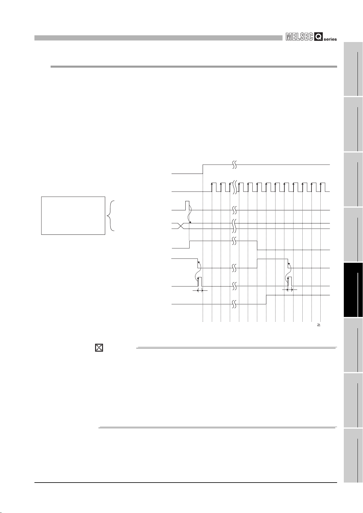
5
FUNCTIONS
5.3 Using the Coincidence Detection Function
When using the coincidence detection function, set any count value in advance. Then, the
QD63P6 compares the value with the present A (Un\G10 and 11)/present value B
(Un\G200 and 201) of the counter, and outputs the counter value coincidence (X02) when
they match.
The coincidence detection can be set for each channel in units of one points.
Figure 5.8 contains I/O numbers (X/Y) and buffer memory addresses for channel 1 only.
For channels 2 to 6, refer to Section 3.3.1 and Section 3.4.1.
(1) Operation of coincidence detection
Count enable command
(Y04)
Counter input pulse
ON
OFF
1
OVERVIEW
2
SYSTEM
CONFIGURATION
3
When Coincidence detection point
change request (Un\G8) status
changes from 1 (Change request) to
0 (No change request), comparison
between the value (100) set in
Coincidence detection point setting
(Un\G6 and 7) and Present value A
(Un\G10 and 11) is started.
Coincidence detection point
change request
(Un\G8)
Coincidence detection point
setting
(Un\G6 and 7)
Counter value small
(X03)
Counter value coincidence
(X02)
Coincidence signal
reset command
(Y01)
Counter value large
(X01)
Present value A
(Un\G10 and 11)
Figure 5.8 Operation example of the coincidence detection function
1
0
ON
OFF
ON
OFF
ON
OFF
ON
OFF
1) 100
0
2)
*2
t*1
3)
3)
5)
t*1
4)
1031021011009998to210
104 105 106 107
POINT
The counter value coincidence (X02) turns ON immediately after power-ON or
reset of the programmable controller CPU since the coincidence detection point
setting (Un\G6 and 7) is 0.
Therefore, perform the following operations.
(1) Write any other than 0 into the coincidence detection point setting (Un\G6 and
7), and 1 into the coincidence detection point change request (Un\G8).
(2) Turn the coincidence signal reset command (Y01) OFF, ON and OFF again.
Note that the ON time must be 2ms or longer.
*1 t 2 ms
SPECIFICATIONS
4
PROCEDURES AND
SETTINGS BEFORE
OPERATION
5
FUNCTIONS
6
UTILITY PACKAGE
(GX Configurator-CT)
7
PROGRAMMING
8
5.3 Using the Coincidence Detection Function
TROUBLESHOOTING
5 - 12

5
FUNCTIONS
Table 5.2 Details of the coincidence detection operation example
No. Description
Coincidence detection is started by the following steps using the value set in the
coincidence detection point setting (Un\G6 and 7).
(1) Write a coincidence detection value (100) into the coincidence detection
point setting (Un\G6 and 7).
1)*
2)
3)
4)
5)
(2) Write 1 (Change request) into the coincidence detection point change
request (Un\G8).
(3) When the coincidence detection point change request (Un\G8) status
changes from 1 (Change request) to 0 (No change request), coincidence
detection is enabled with the value set in the coincidence detection point
setting (Un\G6 and 7).
As long as the present value A (Un\G10 and 11)/present value B (Un\G200 and
201) is smaller than the coincidence detection point setting (Un\G6 and 7), the
counter value small (X03) stays ON.
When the present value A (Un\G10 and 11)/present value B (Un\G200 and 201)
matches the coincidence detection point setting (Un\G6 and 7), the counter
value small (X03) turns OFF, and the counter value coincidence (X02) turns ON.
When the present value A (Un\G10 and 11)/present value B (Un\G200 and 201)
becomes greater than the coincidence detection point setting (Un\G6 and 7),
the counter value large (X01) turns ON.
Turn ON the coincidence signal reset command (Y01), and reset the counter
value coincidence (X02). If the counter value coincidence (X02) remains ON,
the next counter value coincidence (X02) cannot be output.
* Without the operations given in 1), coincidence detection using the value stored in the coincidence
detection point setting (Un\G6 and 7) is not performed.
POINT
• When the sequence program scan time is less than 2ms, be sure to make
the coincidence signal reset command (Y01) turn ON for 2ms or more by
using a timer, etc.
• When the present value A (Un\G10 and 11)/present valueB (Un\G200
and 201) matches the coincidence detection point setting (Un\G6 and 7),
if the coincidence signal reset command (Y01) is turned ON and OFF, the
counter value coincidence (X02) turns ON again.
• Coincidence detection processing inside the QD63P6 may cause the
counter value large (X01) or the counter value small (X03) to turn ON
when the counter value coincidence (X02) status changes from OFF to
ON.
5 - 13
5.3 Using the Coincidence Detection Function

5
FUNCTIONS
(2) Coincidence detection interrupt function
The coincidence detection interrupt function allows making an interrupt request to a
programmable controller CPU at the time of coincidence detection to start the
interrupt program.
(Depending on the programmable controller CPU used, the coincidence detection
interrupt function cannot be used. For details, refer to CHAPTER 2.)
(a) Up to 16-point interrupt factors (SI) are allowed for a single MELSECNET-Q series
intelligent function module.
As shown in Table 5.3, the QD63P6 has 6-point interrupt factors (SI) for
coincidence detection.
Table 5.3 List of interrupt factors
SI No. Interrupt factor
0 Channel 1: Coincidence detection of coincidence detection point
1 Channel 2: Coincidence detection of coincidence detection point
2 Channel 3: Coincidence detection of coincidence detection point
3 Channel 4: Coincidence detection of coincidence detection point
4 Channel 5: Coincidence detection of coincidence detection point
5 Channel 6: Coincidence detection of coincidence detection point
6 to 15 Reserved
1
OVERVIEW
2
SYSTEM
CONFIGURATION
3
SPECIFICATIONS
4
Timing of interrupt signal generation
I/O signals
Internal processing
of programmable
controller CPU
in programmable controller CPU
(b) It takes approx. 150 s from when the QD63P6 detects coincidence until it makes
an interrupt request to a programmable controller CPU.
(c) Select [PLC parameter] - [PLC system] - [Intelligent function module setting] -
[Interrupt pointer settings] to set the interrupt factors (SI) of the QD63P6 and
interrupt pointers of the programmable controller CPU.
1) CPU side [Interrupt pointer start No.]
Counter value coincidence
Program processing
Figure 5.9 Timing of interrupt signal generation
Set the start interrupt pointer number of the programmable controller CPU.
Setting range: 50 to 255
(X02)
Coincidence signal
reset command
(Y01)
Interrupt request
Interrupt request clear
Interrupt program
processing
PROCEDURES AND
SETTINGS BEFORE
OPERATION
5
FUNCTIONS
6
UTILITY PACKAGE
(GX Configurator-CT)
7
PROGRAMMING
8
2) CPU side [Interrupt pointer No. of module]
Set the number of interrupt factors (SI).
Setting range: 1 to 6
5.3 Using the Coincidence Detection Function
TROUBLESHOOTING
5 - 14

5
FUNCTIONS
3) Intelli. module side [Start I/O No.]
Set the start I/O number of the QD63P6.
Setting range: 0000 to 0FE0 (
4) Intelli. module side [Start SI No.]
Set the start interrupt factor (SI) No. of the QD63P6.
Setting range: 0 to 5
The following shows a setting example where SI 0 to 5 of the QD63P6 in the slot
of start I/O No.20 are assigned to interrupt pointers I50 to I55.
H)
Figure 5.10 Interrupt pointer setting example (GX Developer screen)
(d) The following two methods are available for using particular SI numbers only.
1) Using the interrupt pointer setting with parameters
According to the setting in the [Intelligent function module interrupt pointer
setting] dialog box, only the interrupt factors starting from the start SI No. and
equivalent to the number of the pointers are used.
For example, if the start SI No. and No. of pointers are set to 1 and 2
respectively, only SI 1 and 2 will be used.
The interrupt function is not used if the interrupt pointer setting with parameters
has not been made.
2) Using the IMASK instruction from the sequence program
With the IMASK instruction, whether to enable or disable (interrupt mask) the
interrupt program execution can be set to each interrupt pointer number.
For details of the IMASK instruction, refer to QCPU (Q Mode)/QnACPU
Programming Manual (Common Instructions).
5 - 15
5.3 Using the Coincidence Detection Function

5
FUNCTIONS
POINT
• A coincidence detection interrupt occurs when the counter value
coincidence (X02) rises (from OFF to ON). This means that, if the
coincidence signal is reset and unless the counter value coincidence
(X02) is turned OFF, the next interrupt request will not be issued.
• Immediately after power-ON or reset of the programmable controller
CPU, the counter value coincidence (X02) turns ON, however, no
coincidence detection interrupt will occur.
For how to reset the counter value coincidence (X02), refer to Section 5.3
(Figure 5.8).
1
OVERVIEW
2
SYSTEM
CONFIGURATION
3
SPECIFICATIONS
4
PROCEDURES AND
SETTINGS BEFORE
OPERATION
5
FUNCTIONS
6
UTILITY PACKAGE
(GX Configurator-CT)
7
PROGRAMMING
8
5.3 Using the Coincidence Detection Function
TROUBLESHOOTING
5 - 16

5
FUNCTIONS
5.4 Using the Preset Function
The preset function is used to replace the counter's present value A (Un\G10 and 11)/
present value B (Un\G200 and 201) with any given value (preset value), from which the
pulse counting can be started.
(1) Preset function operation
The preset function is activated by turning ON the preset command (Y02) on the
sequence program.
Figure 5.11 contains the I/O numbers (X/Y) and buffer memory addresses of channel
1 only. For channels 2 to 6, refer to Section 3.3.1 and Section 3.4.1.
Count enable command (Y04)
Counter input pulse
Preset value setting (Un\G4 and 5)
Preset command (Y02)
Present value A (Un\G10 and 11)
Figure 5.11 Preset function operation example
No. Description
1)
2)
ON
OFF
ON
OFF
Table 5.4 Details of the preset function operation example
Writes any value into the preset value setting (Un\G4 and 5) of the QD63P6 in
the 32-bit binary format.
When the preset command (Y02) rises (from OFF to ON), a value in the preset
value setting (Un\G4 and 5) is stored in the present value A (Un\G10 and 11)/
present value B (Un\G200 and 201).
The preset function can be executed regardless of the ON/OFF status of the
count enable command (Y04).
1)
1000
t*
2)
101100676665to210
102 103 104 105
* t 2ms
5 - 17
5.4 Using the Preset Function

5
FUNCTIONS
5.5 Using the Periodic Pulse Counter Function
This function allows the present value A (Un\G10 and 11)/present value B (Un\G200 and
201) and the previous value to be stored in the present periodic pulse count value
(Un\G16 and 17) and previous periodic pulse count value (Un\G14 and 15) respectively at
intervals of the preset period time (Un\G9), while the periodic pulse counter start command
(Y05) is ON.
(1) Periodic pulse counter operation
The following explains the relation between respective I/O signals and buffer memory
areas used in the periodic pulse counter function.
The previous periodic pulse count value (Un\G14 and 15) is compared with the
judgment value for updated periodic pulse count value (Un\G18 and 19), and if these
stored values are equal, the present value is stored in the present periodic pulse
count value (Un\G16 and 17).
Figure 5.12 contains the I/O numbers (X/Y) and buffer memory addresses of channel
1 only. For channels 2 to 6, refer to Section 3.3.1 and Section 3.4.1.
For the period setting (Un\G9), refer to Section 3.4.2 (4).
1
OVERVIEW
2
SYSTEM
CONFIGURATION
3
SPECIFICATIONS
4
PROCEDURES AND
SETTINGS BEFORE
OPERATION
5
FUNCTIONS
6
UTILITY PACKAGE
(GX Configurator-CT)
7
PROGRAMMING
8
5.5 Using the Periodic Pulse Counter Function
TROUBLESHOOTING
5 - 18
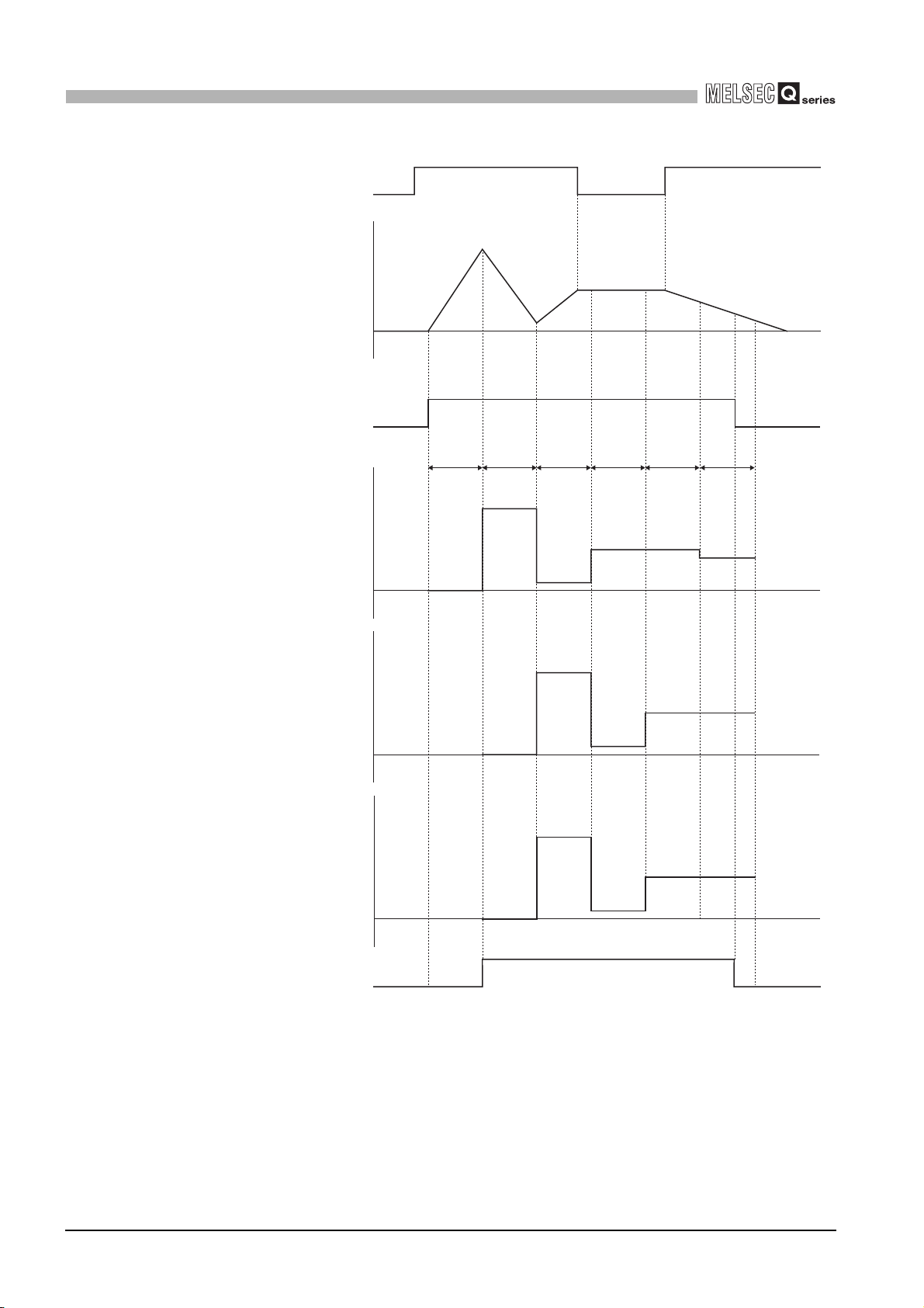
5
FUNCTIONS
Count enable command
(Y04)
Present value A
(Un\G10 and 11)
Periodic pulse counter start command
Present periodic pulse count value
(Y05)
(Un\G16 and 17)
ON
OFF
200
100
ON
OFF
200
100
7)
2)
200
100
5)
100
4)
100
6)
80
T
5)
6)
80
4)
1)
0
0
0
T
(Period setting)
(Un\G9)
1)
0
3)
20
TT
2)
200
100
TT
3)
20
Previous periodic pulse count value
(Un\G14 and 15)
Judgment value for updated
periodic pulse count value
(Un\G18 and 19)
Periodic counter flag
(Un\G13)
Figure 5.12 Periodic pulse counter function operation example
200
100
200
100
3)
200
5)
100
2)
0
0
1
0
0
3)
200
2)
0
8)
4)
20
5)
100
4)
20
6)
100
6)
100
5 - 19
5.5 Using the Periodic Pulse Counter Function

5
FUNCTIONS
Table 5.5 Details of the periodic pulse counter function operation example
No. Description
1)
2)
3)
4)
5)
6)
7)
8)
The counter's present value A (Un\G10 and 11)/present value B (Un\G200 and
201), "0" is stored in the present periodic pulse count value (Un\G16 and 17).
The counter's present value A (Un\G10 and 11)/present value B (Un\G200 and
201), "200" is stored in the present periodic pulse count value (Un\G16 and 17).
The value "0" that was in the present periodic pulse count value (Un\G16 and
17) until then is now stored in the previous periodic pulse count value (Un\G14
and 15). After the update of the present periodic pulse count value (Un\G16 and
17) and the previous periodic pulse count value (Un\G14 and 15), "0" is stored
in the judgment value for updated periodic pulse count value (Un\G18 and 19).
The counter's present value A (Un\G10 and 11)/present value B (Un\G200 and
201), "20" is stored in the present periodic pulse count value (Un\G16 and 17).
The value "200" that was in the present periodic pulse count value (Un\G16 and
17) until then is now stored in the previous periodic pulse count value (Un\G14
and 15). After the update of the present periodic pulse count value (Un\G16 and
17) and the previous periodic pulse count value (Un\G14 and 15), "200" is
stored in the judgment value for updated periodic pulse count value (Un\G18
and 19).
The counter's present value A (Un\G10 and 11)/present value B (Un\G200 and
201), "100" is stored in the present periodic pulse count value (Un\G16 and 17).
The value "20" that was in the present periodic pulse count value (Un\G16 and
17) until then is now stored in the previous periodic pulse count value (Un\G14
and 15).
After the update of the present periodic pulse count value (Un\G16 and 17) and
the previous periodic pulse count value (Un\G14 and 15), "20" is stored in the
judgment value for updated periodic pulse count value (Un\G18 and 19).
The counter's present value A (Un\G10 and 11)/present value B (Un\G200 and
201), "100" is stored in the present periodic pulse count value (Un\G16 and 17).
The value "100" that was in the present periodic pulse count value (Un\G16 and
17) until then is now stored in the previous periodic pulse count value (Un\G14
and 15).
After the update of the resent periodic pulse count value (Un\G16 and 17) and
the previous periodic pulse count value (Un\G14 and 15), "100" is stored in the
judgment value for updated periodic pulse count value (Un\G18 and 19).
The counter's present value A (Un\G10 and 11)/present value B (Un\G200 and
201), "80" is stored in the present periodic pulse count value (Un\G16 and 17).
The value "100" that was in the present periodic pulse count value (Un\G16 and
17) until then is now stored in the previous periodic pulse count value (Un\G14
and 15).
After the update of the present periodic pulse count value (Un\G16 and 17) and
the previous periodic pulse count value (Un\G14 and 15), "100" is stored in the
judgment value for updated periodic pulse count value (Un\G18 and 19).
The periodic pulse counter function is executed regardless of the ON/OFF
status of the count enable command (Y04).
During execution of the periodic pulse counter function, "1" (Operating) is
stored in the periodic counter flag (Un\G13).
1
OVERVIEW
2
SYSTEM
CONFIGURATION
3
SPECIFICATIONS
4
PROCEDURES AND
SETTINGS BEFORE
OPERATION
5
FUNCTIONS
6
UTILITY PACKAGE
(GX Configurator-CT)
7
PROGRAMMING
8
5.5 Using the Periodic Pulse Counter Function
TROUBLESHOOTING
5 - 20
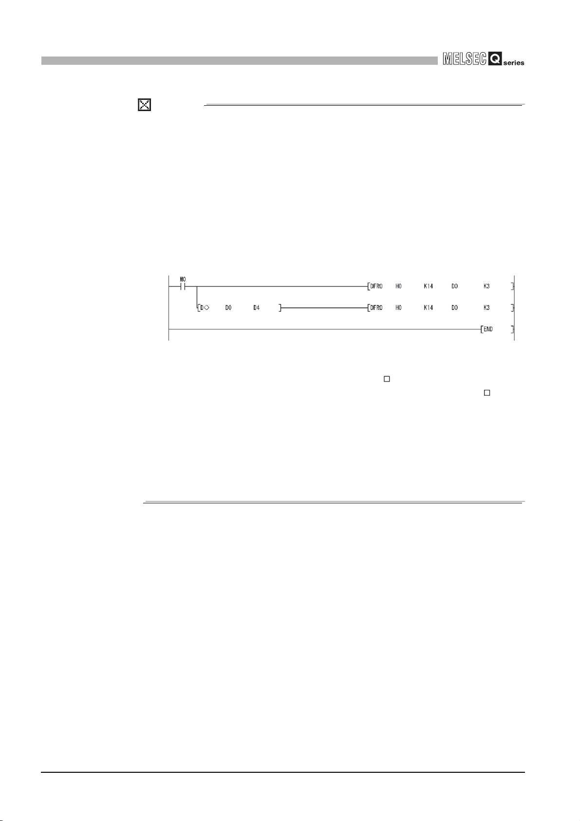
5
FUNCTIONS
POINT
When reading a periodic pulse count value with the sequence program, use either
of the following methods.
(1) Read a data block of six words from the previous periodic pulse count value
(Un\G14 and 15) using the DFRO instruction, and check that the previous
periodic pulse count value (Un\G14 and 15) is equal to the judgment value for
updated periodic pulse count value (Un\G18 and 19). If not equal, try reading
again.
The following example program reads the periodic pulse count value of
channel 1 of the QD63P6 that is mounted in the slot position of I/O number X/
Y00 to X/Y1F when M0 is turned ON.
Figure 5.13 Periodic pulse counter value reading program example
(2) Use the dedicated instruction, G(P).PPCVRD . (Refer to Appendix 1.2.)
When the periodic pulse count value is read with the G(P).PPCVRD
instruction, the determination on consistency in the sequence program is
unnecessary.
If either of the above methods is not used, the previous and present values may
be the same due to the update timing of the module and reading timing of the
sequence program, and may cause inconsistency in the periodic pulse count
values.
5 - 21
5.5 Using the Periodic Pulse Counter Function

5
FUNCTIONS
5.6 Count Response Delay Time
In the QD63P6, a delay will occur in counting in the following cases.
1
(1) When starting counting by the count enable command (Y04), a delay due
to the sequence program scan time will occur.
(2) A delay due to the control cycle (1ms) will occur when executing the
following:
(a) A delay of up to 2ms (1 control cycle 2) will occur from when the count enable
command (Y04) is turned ON/OFF until the present value A (Un\G10 and 11)/
present value B (Un\G200 and 201) is updated in the buffer memory.
(b) A similar delay will occur when the preset command (Y02) is turned from OFF to
ON.
How to calculate the maximum delay time is shown below.
Maximum delay time [ms] = (1 scan time + 2) [ms]
OVERVIEW
2
SYSTEM
CONFIGURATION
3
SPECIFICATIONS
4
PROCEDURES AND
SETTINGS BEFORE
OPERATION
5
5.6 Count Response Delay Time
5 - 22
FUNCTIONS
6
UTILITY PACKAGE
(GX Configurator-CT)
7
PROGRAMMING
8
TROUBLESHOOTING

6
UTILITY PACKAGE (GX Configurator-CT)
CHAPTER6 UTILITY PACKAGE (GX Configurator-CT)
6.1 Utility Package Functions
Table 6.1 shows the functions of the utility package.
Table 6.1 Utility package (GX Configurator-CT) functions list
Function Description Reference
(1) Make the initial settings for each channel to operate the QD63P6.
Set the values of the items where initial settings are required.
CH Preset value setting
CH Coincidence detection point change request
Initial setting
CH Coincidence detection point setting
CH Ring counter lower limit value
CH Ring counter upper limit value
CH Period setting
Section 6.4
Auto refresh
Monitor/Test
(2) Data with initial settings are registered to programmable controller CPU parameters and are
automatically written to the QD63P6 when the programmable controller CPU is in RUN.
(1) Set the buffer memory of the QD63P6 to which auto refresh is to be performed for each
channel.
CH Present value A
CH Present value B
CH Overflow detection flag
CH Periodic counter flag
CH Previous periodic pulse count value
CH Present periodic pulse count value
CH Judgment value for updated periodic pulse count value
CH Error code
(2) The values stored in the QD63P6 buffer memory with auto refresh setting are automatically
read when the programmable controller CPU executes the END instruction.
(1) Monitors/tests the following buffer memories and I/O signals of the QD63P6.
Y device
CH Ring counter lower limit value
CH Ring counter upper limit value
CH Preset value setting
CH Coincidence detection point setting
CH Coincidence detection point change request
CH Period setting
CH Error reset command
(2)Monitors the following buffer memories of the QD63P6.
X device
CH Present value A
CH Present value B
CH Overflow detection flag
CH Error code
CH Periodic counter flag
CH Previous periodic pulse count value
CH Present periodic pulse count value
CH Judgment value for updated periodic pulse count value
Section 6.5
Section 6.6
6 - 1
6.1 Utility Package Functions

6
UTILITY PACKAGE (GX Configurator-CT)
6.2 Installing and Uninstalling the Utility Package
For how to install or uninstall the utility package, refer to "Method of installing the
MELSOFT Series" included in the utility package.
6.2.1 Handling precautions
The following explains the precautions on using the utility package.
1
OVERVIEW
2
(1) For safety
Since the utility is add-in software for GX Developer, read "Safety Precautions" and
the basic operating procedures in the GX Developer Operating Manual.
(2) About installation
GX Configurator-CT is add-in software for GX Developer Version 4 or later.
Therefore, GX Configurator-CT must be installed on the personal computer that has
already GX Developer Version 4 or later installed.
(3) Screen error of Intelligent function module utility
Insufficient system resource may cause the screen to be displayed inappropriately
while using the Intelligent function module utility.
If this occurs, close the Intelligent function module utility, GX Developer (program,
comments, etc.), and other applications, and then start GX Developer and Intelligent
function module utility again.
(4) To start the Intelligent function module utility
(a) In GX Developer, select "QCPU (Q mode)" for PLC series and specify a project.
If any other than "QCPU (Q mode)" is selected for PLC series, or if no project is
specified, the Intelligent function module utility will not start.
(b) Multiple Intelligent function module utilities can be started.
However, [Open parameters] and [Save parameters] operations under [Intelligent
function module parameter] are allowed for one Intelligent function module utility
only. Only the [Monitor/test] operation is allowed for the other utilities.
SYSTEM
CONFIGURATION
3
SPECIFICATIONS
4
PROCEDURES AND
SETTINGS BEFORE
OPERATION
5
FUNCTIONS
6
(5) Switching between two or more Intelligent function module utilities
When two or more Intelligent function module utility screens cannot be displayed side
by side, select a screen to be displayed on the top of others using the task bar.
(6) Number of parameters that can be set in GX Configurator-CT
The remote I/O station in MELSECNET/H network system and CPU module are
limited on the number of parameters can be set to the mounted intelligent function
module using GX Configurator.
6.2 Installing and Uninstalling the Utility Package
6.2.1 Handling precautions
6 - 2
UTILITY PACKAGE
7
8
(GX Configurator-CT)
PROGRAMMING
TROUBLESHOOTING
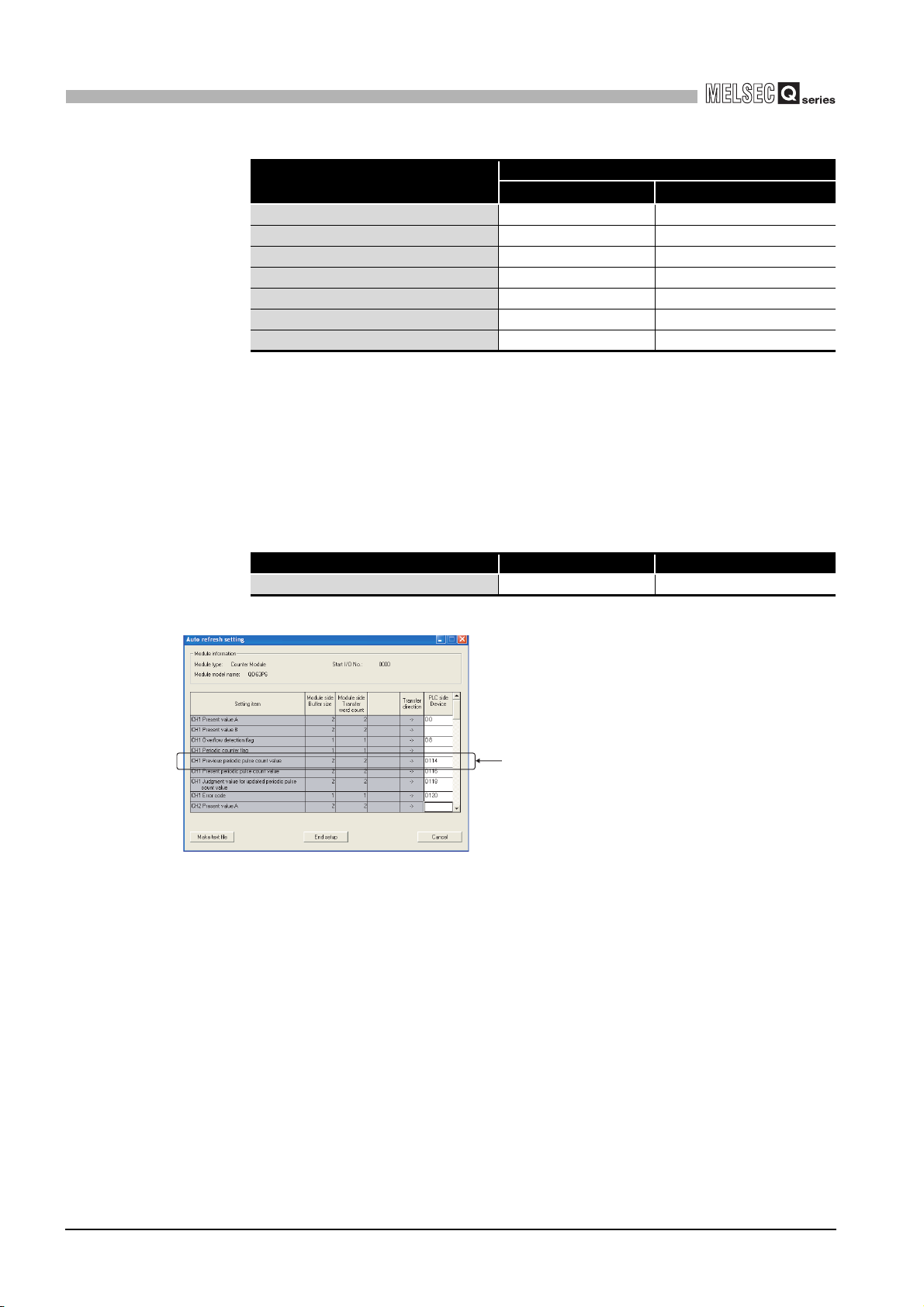
6
UTILITY PACKAGE (GX Configurator-CT)
Table 6.2 Maximum number of settable parameters using GX Configurator
When intelligent function modules
are installed to:
Q00J/Q00/Q01CPU 512 256
Q02/Q02H/Q06H/Q12H/Q25HCPU 512 256
Q12PH/Q25PHCPU 512 256
Q12PRH/Q25PRHCPU 512 256
Q02UCPU 2048 1024
Q03UD/Q04UDH/Q06UDHCPU 4096 2048
MELSECNET/H remote I/O station 512 256
For example, if multiple intelligent function modules are installed to the remote I/O
station, configure the settings in GX Configurator so that the number of parameters
set for all the intelligent function modules does not exceed the limit of the remote I/O
station. Calculate the total number of parameter settings separately for the initial
setting and for the auto refresh setting.
The number of parameters that can be set for one module in GX Configurator-CT is
as shown below.
Maximum number of parameter settings
Initial setting Auto refresh setting
Table 6.3 Number of settable parameters per module
Target module Initial setting Auto refresh setting
QD63P6 6 (fixed) 48 (Max.)
Example) Counting the number of parameter settings in Auto refresh setting
This one row is counted as one
setting.
Blank rows are not counted.
Count up all the setting items on this
screen, and add the total to the
number of settings for other intelligent
function modules to get a grand total.
Figure 6.1 Numeration for the number of parameters set in auto refresh setting
6 - 3
6.2 Installing and Uninstalling the Utility Package
6.2.1 Handling precautions
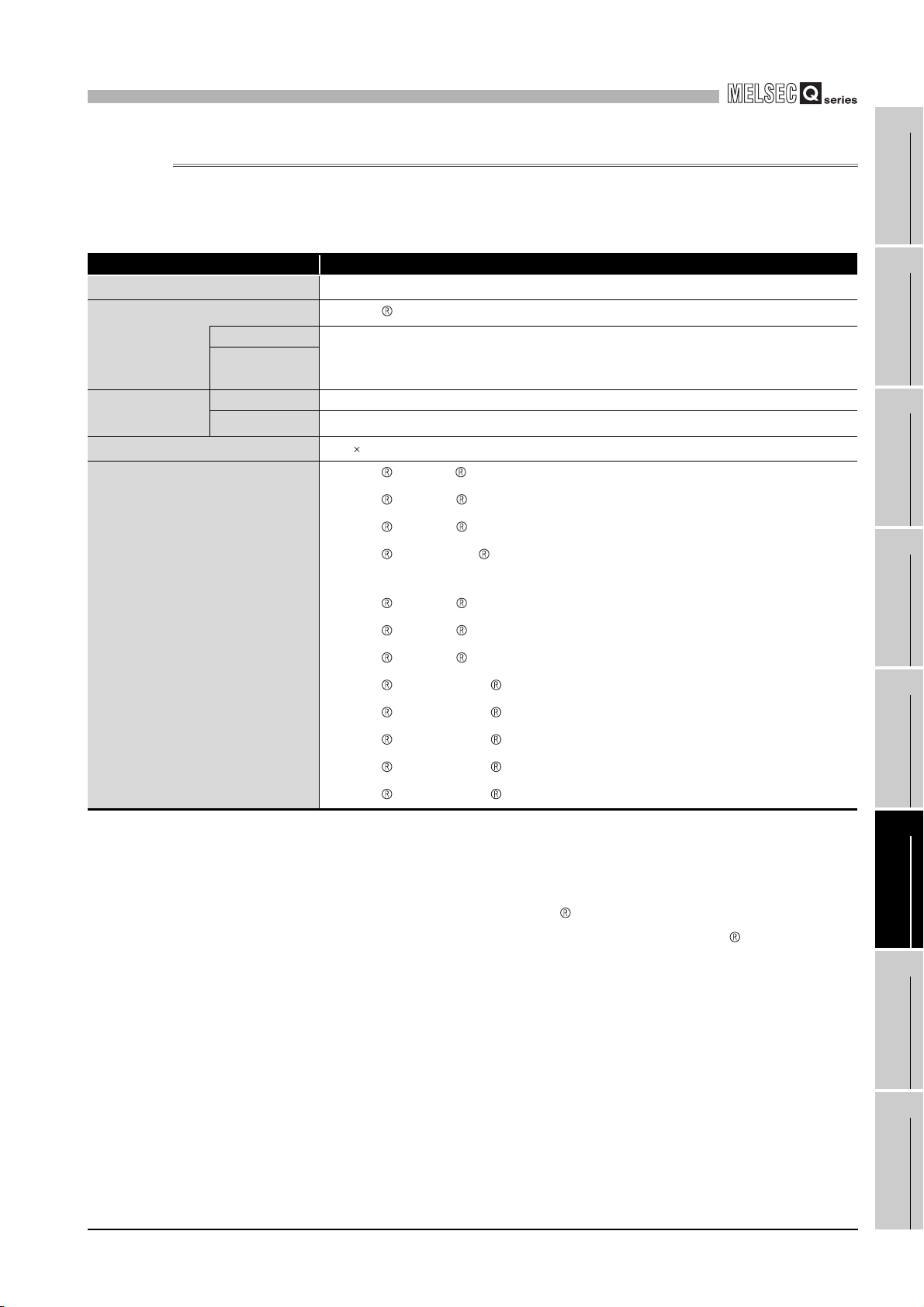
6
UTILITY PACKAGE (GX Configurator-CT)
6.2.2 Operating environment
This section explains the operating environment of the personal computer that runs GX
Configurator-CT.
Item Description
Installation (Add-in) target
Computer
CPU
Required
memory
Hard disk
*3
space
Display
For installation 65 MB or more
For operation 10 MB or more
Table 6.4 Operating environment of the personal computer
*1
Add-in to GX Developer Version 4 (English version) or later.
Windows -based personal computer
Refer to Table 6.5 "Operating system and performance required for personal
computer".
800 600 dots or more resolution
Microsoft Windows 95 Operating System (English version)
Microsoft Windows 98 Operating System (English version)
Microsoft Windows Millennium Edition Operating System (English version)
Microsoft Windows NT Workstation Operating System Version 4.0 (English
version)
*4
1
OVERVIEW
2
*2
SYSTEM
CONFIGURATION
3
SPECIFICATIONS
4
Basic software
Microsoft Windows 2000 Professional Operating System (English version)
Microsoft Windows XP Professional Operating System (English version)
Microsoft Windows XP Home Edition Operating System (English version)
Microsoft Windows Vista Home Basic Operating System (English version)
Microsoft Windows Vista Home Premium Operating System (English version)
Microsoft Windows Vista Business Operating System (English version)
Microsoft Windows Vista Ultimate Operating System (English version)
Microsoft Windows Vista Enterprise Operating System (English version)
* 1 Install GX Configurator-CT in GX Developer Version 4 or higher in the same language.
GX Developer (English version) and GX Configurator-CT (Japanese version) cannot be used in
combination, and GX Developer (Japanese version) and GX Configurator-CT (English version)
cannot be used in combination.
* 2 GX Configurator-CT is not applicable to GX Developer Version 3 or earlier.
* 3 At least 15GB is required for Windows Vista .
* 4 Resolution of 1024 X 768 dots or more is recommended for Windows Vista .
PROCEDURES AND
SETTINGS BEFORE
OPERATION
5
FUNCTIONS
6
UTILITY PACKAGE
(GX Configurator-CT)
7
6.2 Installing and Uninstalling the Utility Package
6.2.2 Operating environment
PROGRAMMING
8
TROUBLESHOOTING
6 - 4

6
UTILITY PACKAGE (GX Configurator-CT)
Table 6.5 Operating system and performance required for personal computer
Operating system
Windows 95 Pentium 133 MHz or more
Windows 98 Pentium 133 MHz or more
Windows Me Pentium 150 MHz or more
Windows NT Workstation 4.0 Pentium 133 MHz or more
Windows 2000 Professional Pentium 133 MHz or more
Windows XP Professional (Service Pack1 or later) Pentium 300 MHz or more
Windows XP Home Edition (Service Pack1 or later) Pentium 300 MHz or more
Windows Vista Home Basic Pentium 1GHz or more
Windows Vista Home Premium Pentium 1GHz or more
Windows Vista Business Pentium 1GHz or more
Windows Vista Ultimate Pentium 1GHz or more
Windows Vista Enterprise Pentium 1GHz or more
Performance required for personal computer
CPU Memory
32 MB or more
32 MB or more
32 MB or more
32 MB or more
64 MB or more
128 MB or more
128 MB or more
1GB or more
1GB or more
1GB or more
1GB or more
1GB or more
POINT
(1) The functions shown below are not available for Windows XP and Windows
Vista .
If any of the following functions is attempted, this product may not operate
normally.
• Start of application in Windows compatible mode
• Fast user switching
• Remote desktop
• Large fonts (Details setting of Display Properties)
Also, 64-bit version Windows XP and Windows Vista are not supported.
(2) Use a USER authorization or higher in Windows Vista .
6 - 5
6.2 Installing and Uninstalling the Utility Package
6.2.2 Operating environment
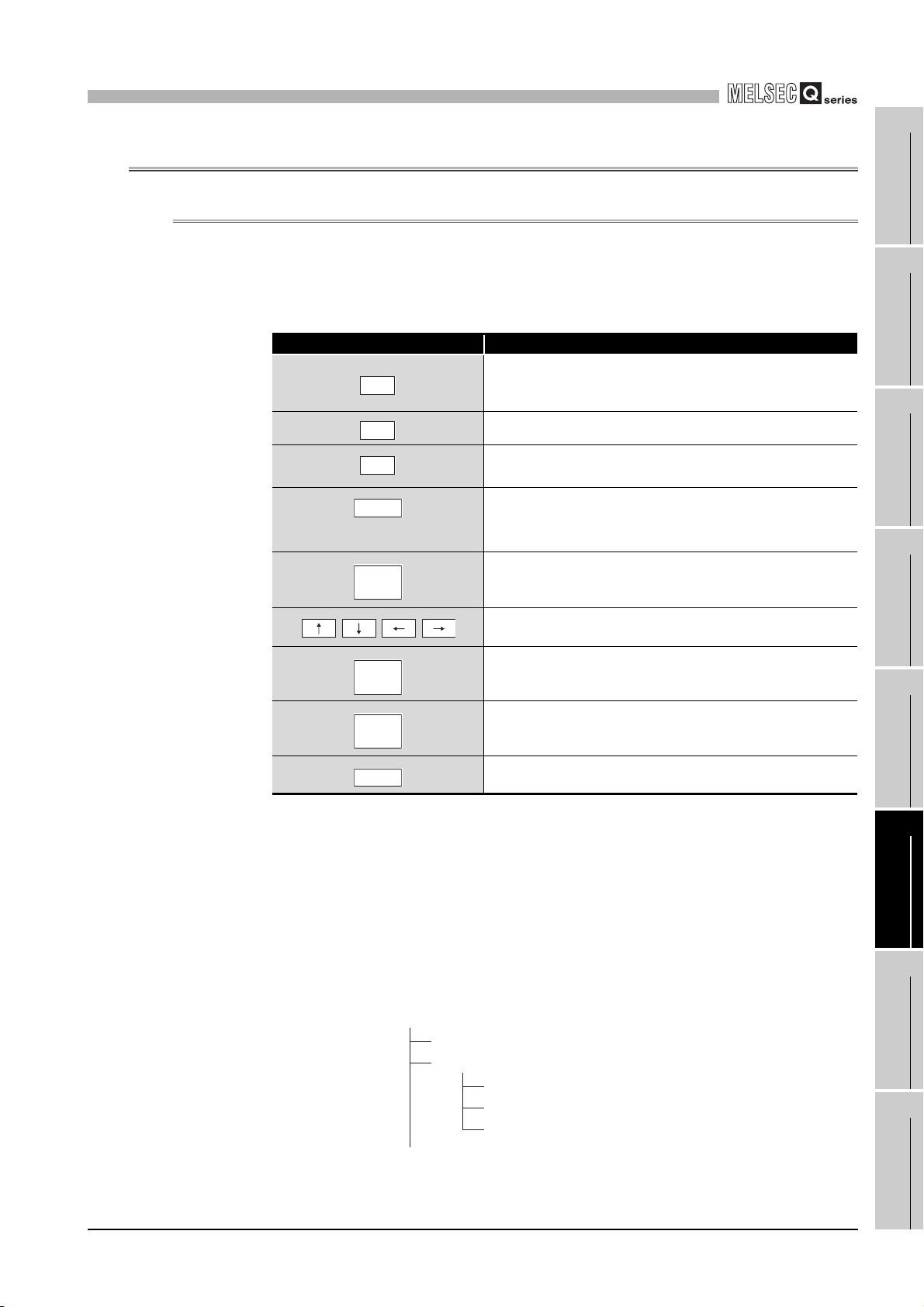
6
r
UTILITY PACKAGE (GX Configurator-CT)
6.3 Utility Package Operation
6.3.1 Common utility package operations
(1) Control keys
Table 6.6 shows the special keys that can be used in operations of the utility package
and their applications.
Key Application
1
OVERVIEW
2
Table 6.6 Control keys
Esc
Ta b
Ctrl
Delete
Back
Space
Page
Up
Page
Down
Enter
Cancels the current entry in a cell.
Closes the window.
Moves between controls in the window.
Used in combination with the mouse operation to select
multiple cells for test execution.
Deletes the character where the cursor is positioned.
When a cell is selected, clears all of the setting contents in
the cell.
Deletes the character where the cursor is positioned.
Moves the cursor.
Moves the cursor one page up.
Moves the cursor one page down.
Completes the entry in the cell.
(2) Data created with the utility package
The following data or files that are created with the utility package can be also
handled in GX Developer. Figure 6.3 shows respective data or files are handled in
which operation.
SYSTEM
CONFIGURATION
3
SPECIFICATIONS
4
PROCEDURES AND
SETTINGS BEFORE
OPERATION
5
FUNCTIONS
6
(3) Intelligent function module parameter
(a) This represents the data created in Auto refresh setting, and they are stored in an
intelligent function module parameter file in a project created by GX Developer.
Project
Program
Parameter
PLC parameter
Network parameter
Intelligent function module paramete
Figure 6.2 Project structure
6.3 Utility Package Operation
6.3.1 Common utility package operations
6 - 6
UTILITY PACKAGE
7
8
(GX Configurator-CT)
PROGRAMMING
TROUBLESHOOTING
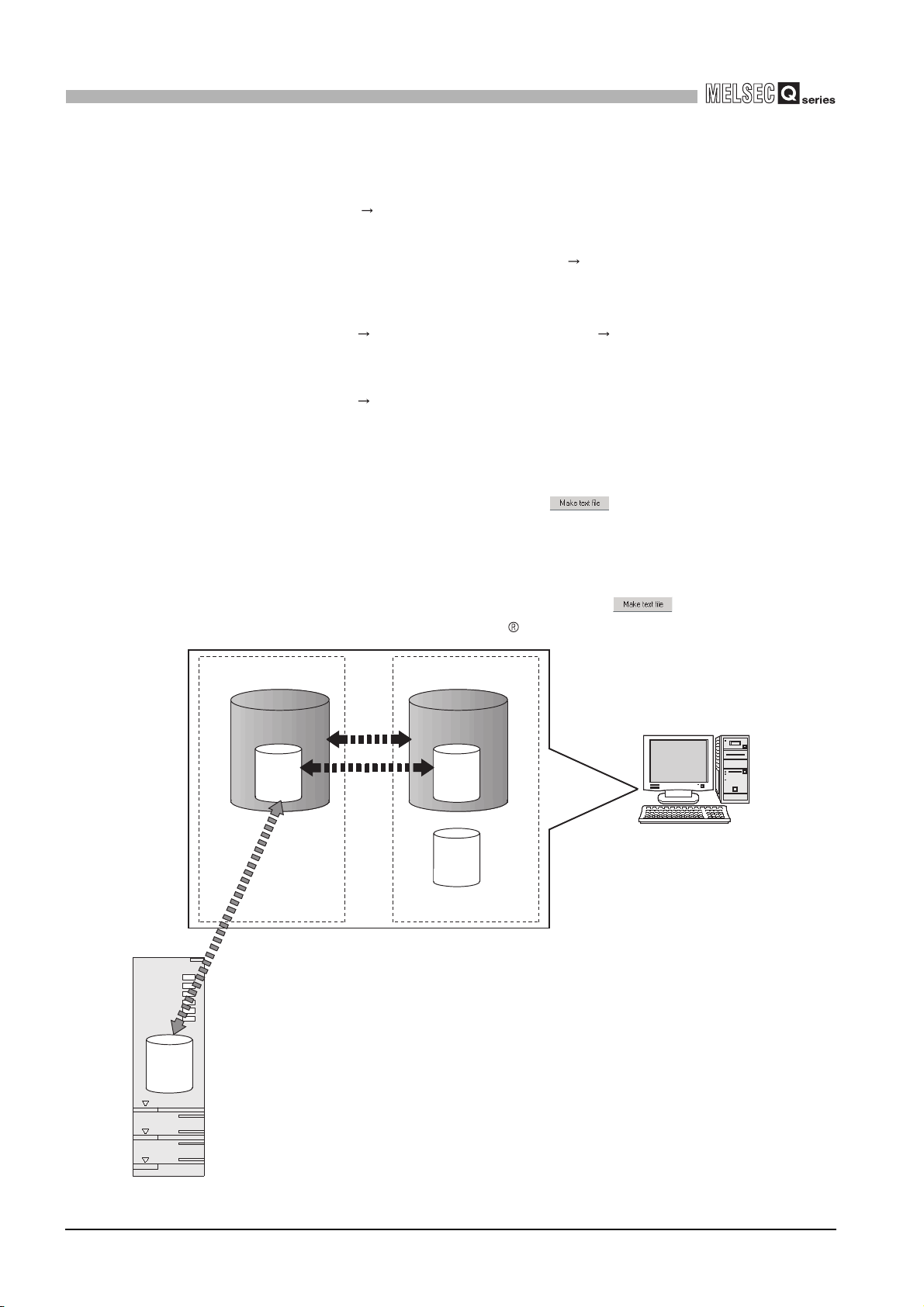
6
UTILITY PACKAGE (GX Configurator-CT)
(b) Steps 1) to 3) shown in Figure 6.3 are performed as follows:
1) From GX Developer, select:
[Project] [Open project]/[Save]/[Save as]
2) From the module selection screen of the utility, select:
[Intelligent function module parameter] [Open parameters]/[Save
parameters]
3) From GX Developer, select:
[Online] [Read from PLC]/[Write to PLC] "Intelligent function module
parameters"
Or, from the module selection screen of the utility,
[Online] [Read from PLC]/[Write to PLC]
(4) Text file
(a) A text file can be created by clicking the button on the initial setting, Auto
refresh setting, or Monitor/Test screen. The text files can be utilized to create user
documents.
QCPU
(b) Text files can be saved in any directory. However, a path (folder where the file is to
be saved) cannot be created during operation of . Therefore, create the
folder beforehand using Windows Explorer.
GX Developer/
GX Configurator-CT
Project
A
3)
1)
2)
A: Intelligent function module parameters
B: Data saved by "Make text file"
Disk
Project
A
Personal computer
B
6 - 7
A
Figure 6.3 Correlation chart for data created with the utility package
6.3 Utility Package Operation
6.3.1 Common utility package operations
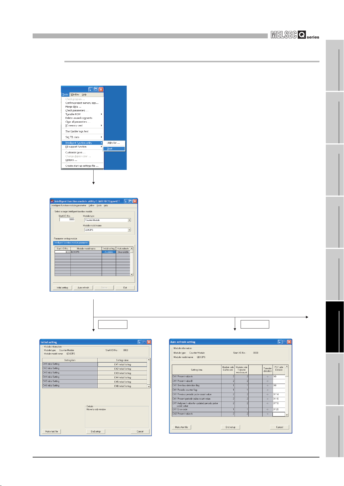
6
UTILITY PACKAGE (GX Configurator-CT)
6.3.2 Operation overview
GX Developer screen
[Tools] - [Intelligent function utility] - [Start]
1
OVERVIEW
2
SYSTEM
CONFIGURATION
3
Screen for selecting a target
intelligent function module
Refer to Section 6.3.3.
Enter "Start I/O No.", and select
"Module type" and "Module model name".
Initial setting Auto refresh
Initial setting screen
Auto refresh setting screen
SPECIFICATIONS
4
PROCEDURES AND
SETTINGS BEFORE
OPERATION
5
FUNCTIONS
6
1)
UTILITY PACKAGE
(GX Configurator-CT)
7
Refer to Section 6.4.
Figure 6.4 General operation
Refer to Section 6.5.
6.3 Utility Package Operation
6.3.2 Operation overview
PROGRAMMING
8
TROUBLESHOOTING
6 - 8

6
UTILITY PACKAGE (GX Configurator-CT)
1)
Selecting monitor/test module screen
Monitor/Test
Monitor/Test screen
[Online] - [Monitor/Test]
Enter "Start I/O No.", and select
"Module type" and "Module model name".
6 - 9
Refer to Section 6.6.
Figure 6.4 General operation (Continued)
6.3 Utility Package Operation
6.3.2 Operation overview

6
UTILITY PACKAGE (GX Configurator-CT)
6.3.3 Starting the Intelligent function module utility
[Purpose]
Start the utility from GX Developer to display the [Intelligent function module parameter
setting module select] screen.
From this screen, [Initial setting], [Auto refresh setting], and [Select monitor/test
module] (selection of the module which performs monitor/test) screens for the
QD63P6 can be started.
[Operating procedure]
[Tools] [Intelligent function utility] [Start]
[Setting screen]
1
OVERVIEW
2
SYSTEM
CONFIGURATION
3
SPECIFICATIONS
4
Figure 6.5 [Intelligent function module utility] screen
[Explanation of items]
(1) Activation of other screens
(a) Initial setting screen
[Start I/O No.*] [Module type] [Module model name]
(b) Auto refresh setting screen
[Start I/O No.*] [Module type] [Module model name]
(c) Monitor/test module selection screen
[Online] [Monitor/Test]
* Enter the start I/O No. in hexadecimal.
PROCEDURES AND
SETTINGS BEFORE
OPERATION
5
FUNCTIONS
6
UTILITY PACKAGE
(GX Configurator-CT)
7
PROGRAMMING
8
6.3 Utility Package Operation
6.3.3 Starting the Intelligent function module utility
TROUBLESHOOTING
6 - 10

6
UTILITY PACKAGE (GX Configurator-CT)
(2) Command buttons
Deletes the initial setting and auto refresh setting of the selected
module.
Closes this screen.
6 - 11
6.3 Utility Package Operation
6.3.3 Starting the Intelligent function module utility

6
UTILITY PACKAGE (GX Configurator-CT)
(3) Menu bar
(a) File menu
Intelligent function module parameters of the project opened by GX Developer are
handled.
[Open parameters] : Reads a parameter file.
[Close parameters] : Closes the parameter file. If any data are
modified, a dialog asking for file saving will
appear.
[Save parameters] : Saves the parameter file.
[Delete parameters] : Deletes the parameter file.
[Open FB support parameter...] : Opens a FB support parameter file.
[Save as FB support parameter...] : Saves a FB support parameter.
1
OVERVIEW
2
SYSTEM
CONFIGURATION
3
[Exit] : Exits the Intelligent function module utility.
(b) Online menu
[Monitor/Test] : Activates the Select monitor/test module
screen.
[Read from PLC] : Reads intelligent function module
parameters from the CPU module.
[Write to PLC] : Writes intelligent function module
parameters to the CPU module.
POINT
(1) Saving intelligent function module parameters in a file
Since intelligent function module parameters cannot be saved in a file by the
project saving operation of GX Developer, save them on the shown module
selection screen.
(2) Reading/writing intelligent function module parameters from/to a
programmable controller using GX Developer
• Intelligent function module parameters can be read from and written into
a programmable controller after having been saved in a file.
• Set a target programmable controller CPU in GX Developer:
[Online] [Transfer setup].
• When mounting the QD63P6 to the remote I/O station, use [Read from
PLC]/[Write to PLC] of GX Developer.
(3) Checking the required utility
While the start I/O is displayed on the Intelligent function module utility setting
screen, " * " may be displayed for the model name.
This means that the required utility has not been installed or the utility cannot
be started from GX Developer.
Check the required utility, selecting [Tools] - [Intelligent function utility] - [Utility
list...] in GX Developer.
SPECIFICATIONS
4
PROCEDURES AND
SETTINGS BEFORE
OPERATION
5
FUNCTIONS
6
UTILITY PACKAGE
(GX Configurator-CT)
7
PROGRAMMING
8
6.3 Utility Package Operation
6.3.3 Starting the Intelligent function module utility
TROUBLESHOOTING
6 - 12

6
UTILITY PACKAGE (GX Configurator-CT)
6.4 Initial Setting
[Purpose]
Make the initial settings for each channel to operate the QD63P6. The following setting
items are available for parameters of [Initial setting].
• Preset value setting • Ring counter lower limit value
• Coincidence detection point change request • Ring counter upper limit value
• Coincidence detection point setting • Period setting
By making the initial settings, the sequence program settings become unnecessary.
[Operating procedure]
"Start I/O No.*" "Module type" "Module model name"
[Setting screen]
* Enter the start I/O No. in hexadecimal.
6 - 13
6.4 Initial Setting
Channel 1
Channel 6
..................
Figure 6.6 [Initial setting] screen

6
UTILITY PACKAGE (GX Configurator-CT)
1
[Explanation of items]
(1) Command buttons
Creates a file containing the screen data in text file format.
Saves the set data and ends the operation.
Cancels the setting and ends the operation.
POINT
Initial settings are stored to the intelligent function module parameters.
The initial settings become effective after writing them to the CPU module and
executing (1) or (2).
(1) Change RUN/STOP switch on the CPU module STOP, RUN, STOP, and RUN
again.
(2) After changing the switch to RUN, power OFF and then ON the CPU module
or reset it.
When the initial setting contents are written with the sequence program, the initial
settings are executed when the RUN/STOP switch is changed to STOP and RUN
again, and initial setting values are written.
When the CPU module is switched to STOP and RUN again, execute the initial
settings with the sequence program again.
OVERVIEW
2
SYSTEM
CONFIGURATION
3
SPECIFICATIONS
4
PROCEDURES AND
SETTINGS BEFORE
OPERATION
5
6.4 Initial Setting
6 - 14
FUNCTIONS
6
UTILITY PACKAGE
(GX Configurator-CT)
7
PROGRAMMING
8
TROUBLESHOOTING

6
UTILITY PACKAGE (GX Configurator-CT)
6.5 Auto Refresh
[Purpose]
Set the buffer memory of the QD63P6 to which auto refresh is to be performed for
each channel.
The following setting items are available for parameters of [Auto refresh setting].
• Present value A • Previous periodic pulse count value
• Present value B • Present periodic pulse count value
• Overflow detection flag • Judgment value for updated periodic pulse count value
• Periodic counter flag • Error code
This auto refresh setting eliminates the need for reading by sequence programs.
[Operating procedure]
"Start I/O No.*" "Module type" "Module model name"
[Setting screen]
* Enter the start I/O No. in hexadecimal.
6 - 15
Figure 6.7 [Auto refresh setting] screen
6.5 Auto Refresh

6
UTILITY PACKAGE (GX Configurator-CT)
[Explanation of items]
(1) Items
Module side Buffer size : Displays the buffer memory size of the setting item.
Module side Transfer word
count
Transfer direction :
PLC side Device : Enter a CPU module side device that is to be
: Displays the number of words to be transferred.
" " indicates that data are written from the
programmable controller CPU to the buffer memory.
" " indicates that data are loaded from the buffer
memory to the programmable controller CPU.
automatically refreshed.
Applicable devices are X, Y, M, L, B, T, C, ST, D, W,
R, and ZR.
When using bit devices X, Y, M, L or B, set a number
that can be divided by 16 points (examples: X10,
Y120, M16, etc.)
Also, buffer memory data are stored in a 16-point
area, starting from the specified device number. For
example, if X10 is entered, data are stored in X10 to
X1F.
1
OVERVIEW
2
SYSTEM
CONFIGURATION
3
SPECIFICATIONS
4
(2) Command buttons
Creates a file containing the screen data in text file format.
Saves the set data and ends the operation.
Cancels the setting and ends the operation.
POINT
• The auto refresh settings are stored in an intelligent function module
parameter file.
The auto refresh settings become effective by turning the power OFF and
then ON or resetting the CPU module after writing the intelligent function
module parameters to the CPU module.
• The auto refresh settings cannot be changed from sequence programs.
However, processing equivalent to auto refresh can be added using the
FROM/TO instruction in the sequence program.
PROCEDURES AND
SETTINGS BEFORE
OPERATION
5
FUNCTIONS
6
UTILITY PACKAGE
(GX Configurator-CT)
7
PROGRAMMING
8
6.5 Auto Refresh
TROUBLESHOOTING
6 - 16

6
UTILITY PACKAGE (GX Configurator-CT)
6.6 Monitoring/Test
6.6.1 Monitoring/Test
[Purpose]
Start buffer memory monitoring/testing and I/O signal monitoring/testing from this
screen.
[Operating procedure]
"Select monitor/test module" screen "Start I/O No.*" "Module type" "Module
model name"
* Enter the start I/O No. in hexadecimal.
The screen can also be started from System monitor of GX Developer Version 6 or
later.
Refer to the GX Developer Operating Manual for details.
6 - 17
6.6 Monitoring/Test
6.6.1 Monitoring/Test
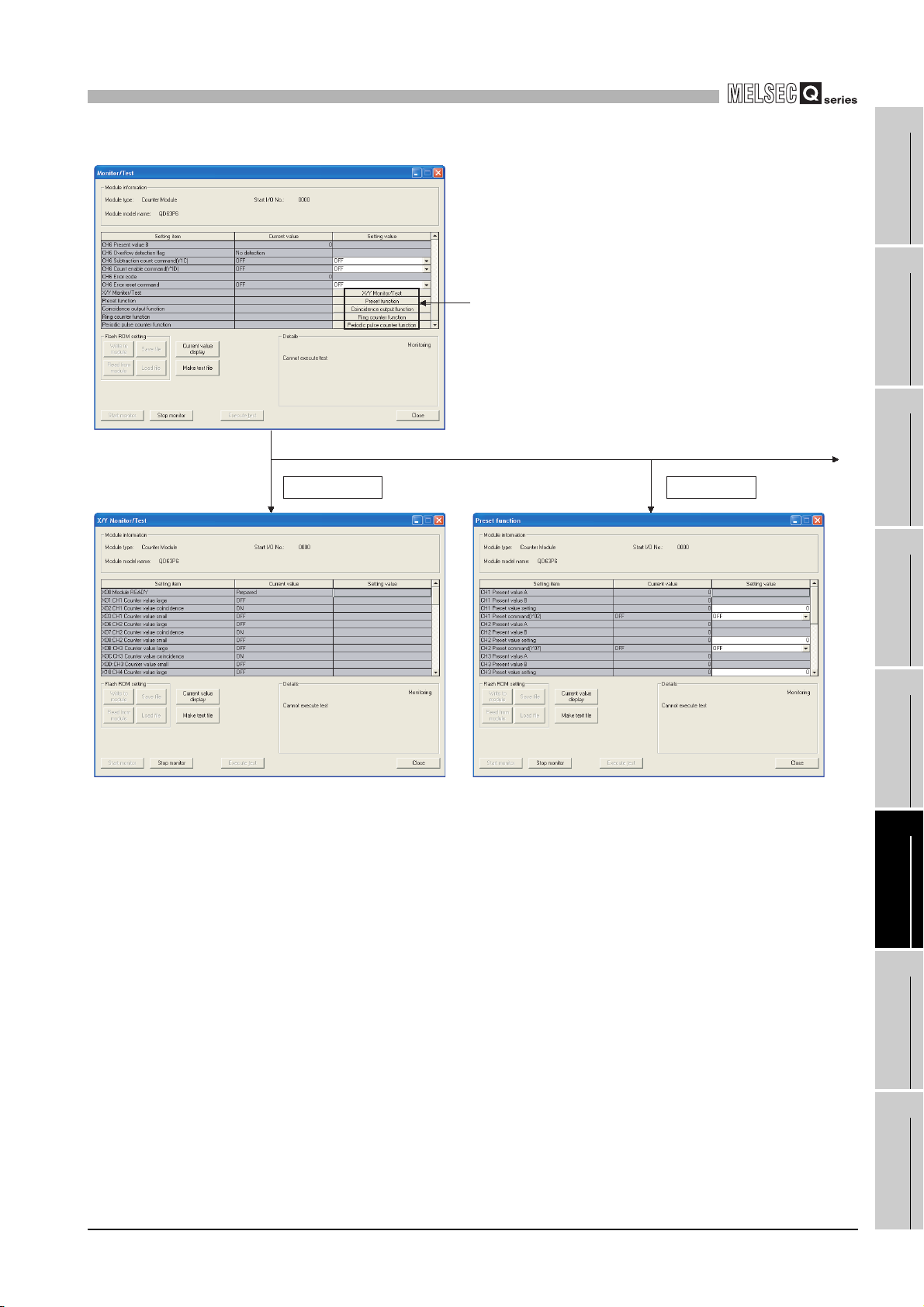
6
UTILITY PACKAGE (GX Configurator-CT)
[Setting screen]
Selecting these buttons displays
the following screens.
1
OVERVIEW
2
SYSTEM
CONFIGURATION
3
1)
Preset functionX/Y Monitor/Test
SPECIFICATIONS
4
Figure 6.8 [Monitor/Test] screen
PROCEDURES AND
SETTINGS BEFORE
OPERATION
5
FUNCTIONS
6
UTILITY PACKAGE
(GX Configurator-CT)
7
PROGRAMMING
8
6.6 Monitoring/Test
6.6.1 Monitoring/Test
TROUBLESHOOTING
6 - 18

6
1)
UTILITY PACKAGE (GX Configurator-CT)
Coincidence detection
function
Ring counter function
Periodic pulse counter
function
6 - 19
Figure 6.8 [Monitor/Test] screen (Continued)
6.6 Monitoring/Test
6.6.1 Monitoring/Test

6
UTILITY PACKAGE (GX Configurator-CT)
[Explanation of items]
(1) Items
Setting item : Displays I/O signals and buffer memory names.
Current value : Monitors the I/O signal states and present buffer memory values.
Setting value : Enter or select values to be written into the buffer memory for test
operation.
(2) Command buttons
Displays the current value of the item selected. (This is
used to check the text that cannot be displayed in the
current value field. However, in this utility package, all
items can be displayed in the display fields).
Creates a file containing the screen data in text file
format.
/
Selects whether or not to monitor current values.
Performs a test on the selected items. To select more
than one item, select them while holding down the
key.
Ctrl
Closes the screen that is currently open and returns to
the previous screen.
1
OVERVIEW
2
SYSTEM
CONFIGURATION
3
SPECIFICATIONS
4
Remark
The following describes an example when [Execute test] settings are changed as
follows:
• Period setting: 3000 ms
• Periodic pulse counter start command (Y05): ON
(1) Click [Setting value] field for [CH Period setting] to select it.
(2) After inputting a period [unit: 10 ms] (input "300" in case of the above
example), press the key.
At this moment, the input value has not yet been written to the QD63P6.
(3) Select [ON] in [Setting item] field of [CH Periodic pulse counter start
command (Y05)].
(4) Select the [Setting value] fields input in (1) to (3) while pressing the
key. Dragging operation using the mouse can also select multiple items.
(5) Click the button for writing.
After the writing, the written value is updated in the [Current value] field.
Enter
Ctrl
PROCEDURES AND
SETTINGS BEFORE
OPERATION
5
FUNCTIONS
6
UTILITY PACKAGE
(GX Configurator-CT)
7
PROGRAMMING
8
6.6 Monitoring/Test
6.6.1 Monitoring/Test
TROUBLESHOOTING
6 - 20

7
PROGRAMMING
CHAPTER7 PROGRAMMING
This chapter describes programs using channel 1 of QD63P6, whose system configuration
example shown below, in the following two cases:
• GX Configurator-CT is used
• GX Configurator-CT is not used
When applying any of the program examples introduced in this chapter to the actual
system, verify the applicability and confirm that no problem occurs in the system control.
(1) System configuration
QX10 (X20 to X2F)
QY10 (Y30 to Y3F)
QD63P6
(X/Y0 to X/Y1F)
Figure 7.1 System configuration
(2) Setting conditions of the intelligent function module switch
Set the pulse input mode, counting speed setting, counter format, and present value
selection setting with the intelligent function module switch on GX Developer. (Refer
to Section 4.5.)
Table 7.1 Setting conditions of the intelligent function module switch
Pulse input mode
CH1 1 multiple of 2 phases 200 kPPS Present value A
Counting speed
setting
Present value
selection setting
(3) Program conditions
This program uses the QD63P6 to perform counting on the conditions listed below.
Table 7.2 Initial setting
Item Setting value
Preset value setting 2500
Coincidence detection point change request Change request
Coincidence detection point setting 1000
Ring counter lower limit value *1 -5000
Ring counter upper limit value *1 5000
Period setting *2 500 (5000ms)
* 1 Set this only when using the ring counter function.
* 2 Set this only when using the periodic pulse counter function.
7 - 1
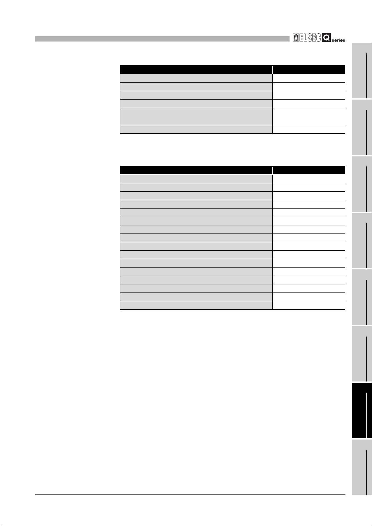
7
PROGRAMMING
CH1 Present value A D0
CH1 Overflow detection flag *1 D8
CH1 Previous periodic pulse count value *2 D114
CH1 Present periodic pulse count value *2 D116
CH1 Judgment value for updated periodic pulse
count value
CH1 Error code D120
* 1 Set this only when using the linear counter function.
* 2 Set this only when using the periodic pulse counter function.
Count operation start signal X20
Present value read signal X21
Preset command signal X22
Count operation stop signal X23
Coincidence LED clear signal X24
Periodic pulse count data read signal *1 X25
Periodic pulse count start signal *1 X26
Error reset command X27
Coincidence confirmation LED signal Y30
Overflow occurrence confirmation LED signal *2 Y31
Error occurrence confirmation LED signal Y32
Present value storage D0 to D1
Previous periodic pulse count value storage *1 D2 to D3
Present periodic pulse count value storage *1 D4 to D5
Overflow status storage *2 D8
Error code storage *3 D9
Table 7.3 Auto refresh setting
Item Setting value
*2 D118
Table 7.4 Devices used by users
Item Device
1
OVERVIEW
2
SYSTEM
CONFIGURATION
3
SPECIFICATIONS
4
PROCEDURES AND
SETTINGS BEFORE
OPERATION
5
* 1 Set this only when using the periodic pulse counter function.
* 2 Set this only when using the linear counter function.
* 3 Stores the last occurred error and retains even after error reset.
7 - 2
FUNCTIONS
6
UTILITY PACKAGE
(GX Configurator-CT)
7
PROGRAMMING
8
TROUBLESHOOTING
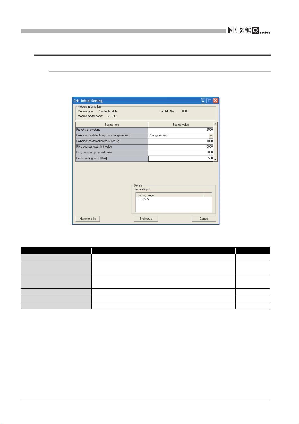
7
PROGRAMMING
7.1 Program Example when GX Configurator-CT is Used
7.1.1 GX Configurator-CT operation
(1) Initial setting (refer to Section 6.4.)
Figure 7.2 shows settings have to be made.
Figure 7.2 [Initial setting] screen
Table 7.5 Items on the [Initial setting] screen
Setting item Description Setting
Preset value setting Set the preset value. 2500
Coincidence detection point
change request
Coincidence detection point
setting
Ring counter lower limit value Set this only when using the ring counter function. -5000
Ring counter upper limit value Set this only when using the ring counter function. 5000
Period setting [unit: 10ms] Set this only when using the periodic pulse counter function. 500
Set this to enable the coincidence detection point setting.
Set the value for coincidence detection point. 1000
Change
request
7 - 3
7.1 Program Example when GX Configurator-CT is Used
7.1.1 GX Configurator-CT operation

7
PROGRAMMING
(2) Auto refresh setting (refer to Section 6.5.)
Set the values on the screen as shown in Figure 7.3. (Channel 1 is used.)
Figure 7.3 [Auto refresh setting] screen
1
OVERVIEW
2
SYSTEM
CONFIGURATION
3
SPECIFICATIONS
4
Table 7.6 Items on the [Auto refresh setting] screen
Setting item Description Setting
CH1 Present value A Set a device for storing the present value. D0
CH1 Present value B Not used. -
CH1 Previous periodic pulse
count value
CH1 Present periodic pulse count
value
CH1 Judgment value for updated
periodic pulse count value
CH1 Periodic counter flag Not used. -
CH1 Overflow detection flag
CH1 Error code Set a device for storing the error code. D120
Set a device for storing the previous periodic pulse count value when
using the periodic pulse counter function.
Set a device for storing the present periodic pulse count value when
using the periodic pulse counter function.
Set a device for storing the judgment value for updated periodic pulse
count value when using the periodic pulse counter function.
Set a device for storing the overflow detection result when using the
linear counter function.
D114
D116
D118
D8
(3) Writing the intelligent function module parameters (refer to Section
6.3.3.)
Write the intelligent function module parameters to the programmable controller CPU.
Perform this operation on the [Intelligent function module parameter setting module
select] screen.
PROCEDURES AND
SETTINGS BEFORE
OPERATION
5
FUNCTIONS
6
UTILITY PACKAGE
(GX Configurator-CT)
7
7.1 Program Example when GX Configurator-CT is Used
7.1.1 GX Configurator-CT operation
PROGRAMMING
8
TROUBLESHOOTING
7 - 4

7
PROGRAMMING
7.1.2 Program example
<Initial setting>
Module
CH1
Count
enable
command
Count
operation
start signal
Count
operation
stop signal
CH1
Counter
value
coincidence
Initial
setting
completed
signal
READY
<Count operation start>
Module
READY
<Count operation stop>
Module
READY
<Processing at count coincidence>
Module
READY
CH1
Coincidence
signal reset
command
CH1
Coincidence
signal reset
command
Initial setting
completed
signal
CH1
Count
enable
command
CH1
Count
enable
command
Coincidence
confirmation
LED signal
Set only when the
counter value
coincidence (X02)
is turned OFF at
initial setting.
CH1
Counter
value
coincidence
CH1
Counter
value
coincidence
<Preset execution>
Module
Preset
READY
command
signal
<Periodic pulse counter function>
Module
Periodic
READY
pulse count
data read
command
Periodic pulse
count start
command
Coincidence
LED clear
signal
CH1
Coincidence
signal reset
command
Previous
periodic
pulse count
value
Judgment value
for updated
periodic pulse
count value
Previous
periodic
pulse count
value
Previous
periodic
pulse count
value
storage
CH1
Coincidence
signal reset
command
CH1
Coincidence
signal reset
command
CH1 Preset
command
CH1 Periodic
pulse counter
start command
Set only when the
periodic pulse
counter function
is used.
7 - 5
7.1 Program Example when GX Configurator-CT is Used
7.1.2 Program example
 Loading...