

Page 1
HVAC Advanced Products Division
SPLIT-TYPE, AIR CONDITIONERS
TECHNICAL MANUAL
PUG OUTDOOR UNIT
MODELS
PUG18AYB
PUG24AYB
PUG30AYB
PUG36AYB
PUG42AYB
036-21534-001 Rev. B (0703)
Table 1:
APPLIES TO:
VOLTAGE PHASE SUFFIX
208/230 VAC 1 PH AYB
Page 2

036-21534-001 Rev. B (0703)
1
DESCRIPTION AND FEATURES
DESCRIPTION AND FEATURES . . . . . . . . . . . . . . . . . . 2
SPECIFICATIONS . . . . . . . . . . . . . . . . . . . . . . . . . . . . . . 3
STANDARD OPERATING DATA . . . . . . . . . . . . . . . . 4-6
PERFORMANCE DATA - OPERATING PRESSURES 7-19
DIMENSIONS AND CLEARANCES . . . . . . . . . . . . . . . 20
SYSTEM CHARGE . . . . . . . . . . . . . . . . . . . . . . . . . . . . 21
OPERATING PRESSURES / SUPERHEAT . . . . . . 21-22
OPERATING RANGE . . . . . . . . . . . . . . . . . . . . . . . . . . 23
The PUG condensing units are cooling only models that are
designed specifically for use with Mitsubishi Electronics PK,
PC, and PL MR. SLIM indoor units of matching nominal
capacities. Models from 1.5 through 3.5 tons are available.
• QUALITY CONDENSER COILS - The coil is constructed of enhanced copper tube and aluminum fins.
• COIL PROTECTION - Coils are protected from damage by a polymer mesh applied between the coil face
and the PVC coated steel coil guard.
• PROTECTED COMPRESSOR - The compressor is
internally protected against high pressure and temperature. This is accomplished by the simultaneous operation of high and low pressure switches and a
temperature sensor that protects the compressor if
undesirable operating conditions occur. A liquid line filter-drier further protects the compressor.
• DURABLE FINISH - The cabinet is made of prepainted steel. The pre-treated flat galvanized steel provides a better paint to steel bond, which resists corrosion and rust creep. Special primer formulas and
matted desert sand finish insure less fading when
exposed to sunlight.
• LOWER INSTALLED COST - Installation time and
costs are reduced by easy power and control wiring
connections. Discharge line heat exchanger knockouts are provided, if required. The unit contains
enough refrigerant for matching indoor units and 25
feet of interconnecting piping. The small base dimension means less space is required on the ground or
roof.
REFRIGERANT CHARGE (R-22 0z.) ADJUSTMENT FOR
OPTIMUM PERFORMANCE . . . . . . . . . . . . . . . . . . . . 24
CAPACITY CORRECTION FACTORS FOR VARIOUS PIPE
LENGTHS . . . . . . . . . . . . . . . . . . . . . . . . . . . . . . . . . . . 25
MICROPROCESSOR CONTROL . . . . . . . . . . . . . . .26-27
ELECTRICAL . . . . . . . . . . . . . . . . . . . . . . . . . . . . . . . . 28
REFRIGERANT SYSTEM . . . . . . . . . . . . . . . . . . . . . . . 29
PARTS BREAKDOWN . . . . . . . . . . . . . . . . . . . . . . .30-32
NOTES . . . . . . . . . . . . . . . . . . . . . . . . . . . . . . . . . . . . . 33
• TOP DISCHARGE - The warm air from the top
mounted fan is blown up away from the structure and
any landscaping. This allows compact location on
multi-unit applications.
• ADVANCED CONTROL BOARD - Each unit is
equipped with an advanced electronic control board.
This board controls the function of the outdoor unit and
improves the operation and protection of the unit. The
control board also provides operational and diagnostic
information to the service technician through multiple
LED’s.
• LOW OPERATING SOUND LEVEL - The upward air
flow carries the normal operating noise up away from
the living area. The rigid top panel effectively isolates
any motor sound. Isolator mounted compressor and
the rippled fins of the condenser coil muffle the normal
fan motor and compressor operating sounds.
• LOW MAINTENANCE - Long life permanently lubri-
cated motor-bearings need no annual servicing.
• EASY SERVICE ACCESS - Fully exposed re fri g era n t
connections, a single panel covering the electrical controls and a plug in the control box connecting the condenser fan, make for easy servicing of the unit.
• SECURED SERVICE V ALVES - Secured reusabl e ser-
vice valves are provided on both the liquid and vapor
connections for ease of evacuating and charging.
• ETL LISTED - Approved for outdoor application.
• Certified in accordance with the Unitary Small Equipment certification program, which is based on ARI
Standard 210/240.
2 Mitsubishi Electronics 2003
Page 3
2
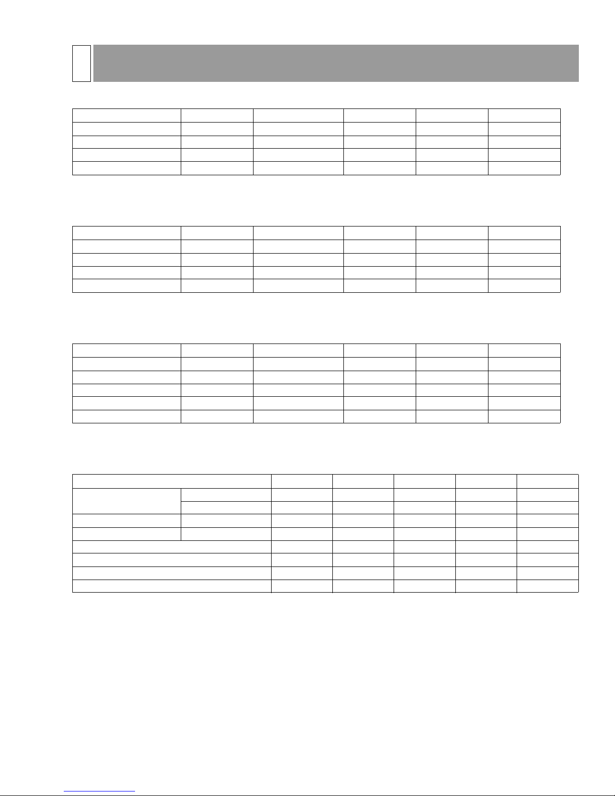
SPECIFICATIONS
PK SERIES - AIR CONDITIONING SYSTEMS
SYSTEM INDOOR OUTDOOR BTU/H* S.E.E.R. E.E.R.*
PKG18FK3 PK18FK3 PUG18AYB 19400 11.60 10.65
PKG24FK3 PK24FK3 PUG24AYB 23400 11.00 9.80
PKG30FK3 PK30FK3 PUG30AYB 29200 11.60 10.20
PKG36FK3 PK36FK3 PUG36AYB 34200 11.40 10.25
* Conditions taken at ARI A (95° F outdoor / 80° F DB, 67° F WB indoor)
Based on ARI operating conditions. Specifications subject to change without notice.
PC SERIES - AIR CONDITIONING SYSTEMS
SYSTEM INDOOR OUTDOOR BTU/H* S.E.E.R. E.E.R.*
PCG24GK PC24GK PUG24AYB 24400 10.50 9.35
PCG30GK PC30GK PUG30AYB 29800 11.00 9.65
PCG36GK PC36GK PUG36AYB 36000 11.20 10.05
PCG42GK PC42GK PUG42AYB 41500 10.00 9.50
* Conditions taken at ARI A (95° F outdoor / 80° F DB, 67° F WB indoor)
Based on ARI operating conditions. Specifications subject to change without notice.
036-21534-001 Rev. B (0703)
PL SERIES - AIR CONDITIONING SYSTEMS
SYSTEM INDOOR OUTDOOR BTU/H* SEER. EER.*
PLG18AK PL18AK PUG18AYB 20000 11.40 10.50
PLG24AK PL24AK PUG24AYB 24000 10.00 9.00
PLG30AK PL30AK PUG30AYB 28400 10.30 9.30
PLG36AK PL36AK PUG36AYB 35600 11.00 9.90
PLG42AK PL42AK PUG42AYB 41000 10.00 9.25
* Conditions taken at ARI A (95° F outdoor / 80° F DB, 67° F WB indoor)
Based on ARI operating conditions. Specifications subject to change without notice.
ELECTRICAL SPECIFICATIONS - AIR CONDITIONING CONDENSING UNITS
MODEL PUG18AYB PUG24AYB PUG30AYB PUG36AYB PUG42AYB
Compressor
Outdoor Fan Full Load Amps 0.5 0.5 0.5 1.4 1.4
Unit Total Full Load Amps 10.1 12.6 15.2 17.4 21.4
Max. Fuse Size (Amps) 20 25 30 35 45
Min. Circuit Ampacity 12.5 15.5 18.9 21.4 26.4
Max. Tubing Length 75 75 75 75 75
Max. Vertical Separation 50 50 50 50 50
Locked Rotor Amps 54 57 73 82 129
Full Load Amps 9.6 12.1 14.7 16.0 20.0
Mitsubishi Electronics 2003 3
Page 4
036-21534-001 Rev. B (0703)
3
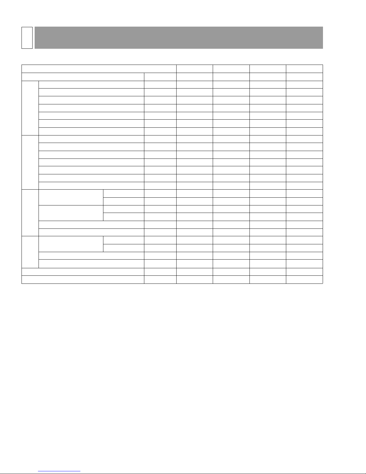
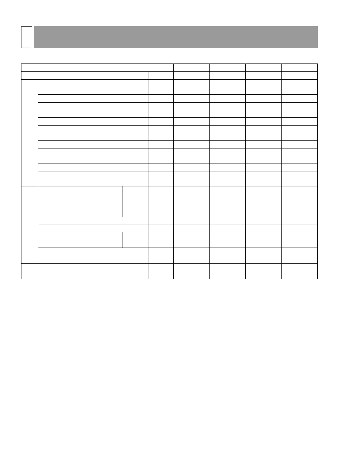
STANDARD OPERATING DATA
PK-FK INDOOR UNITS WITH PUG OUTDOOR UNITS
MODELS PK18FK PK24FK PK30FK PK36FK
Item Unit Cooling Cooling Cooling Cooling
Voltage V 208/230 208/230 208/230 208/230
Frequency Hz 60 60 60 60
Total Input kW 1.82 2.38 2.85 3.34
Indoor Fan Current A 0.8 0.8 0.9 1.0
Booster Heater Current A -- -- -- -Outdoor Fan Current (FLA) A 0.5 0.5 0.5 1.4
Electrical Circuit
Compressor Current (230v) A 7.3 9.6 12.6 14.0
Condensing Pressure PSIG 260 271 287 278
Suction Pressure PSIG 85 86 84 77
Discharge Temperature °F 182 191 196 191
Condensing Temperature °F 107 112 109 112
Suction Temperature °F 62 58 61 59
Refrigerant Pipe Length FT. 25 25 25 25
Refrigerant Circuit
Refrigerant Charge - 3 lbs 8 oz 3 lbs 6 oz 4 lbs 3 oz 3 lbs 15 oz
Intake Air Temperature
Discharge Air Temperature
Indoor Side
Fan Speed RPM. 1490 1490 1490 1490
Airflow (High) CFM 710 710 990 990
Intake Air Temperature
Fan Speed RPM. 1050 1050 1050 1100
Airflow (High) CFM 1690 1785 1600 2340
Outdoor Side
Capacity BTU/H 19400 23400 29200 34200
SHF --0.770.710.690.65
DB °F 80 80 80 80
WB °F 67 67 67 67
DB °F 60 58 58 58
WB °F 59 57 56 56
DB °F 95 95 95 95
WB °F -- -- -- --
4 Mitsubishi Electronics 2003
Page 5
036-21534-001 Rev. B (0703)
3
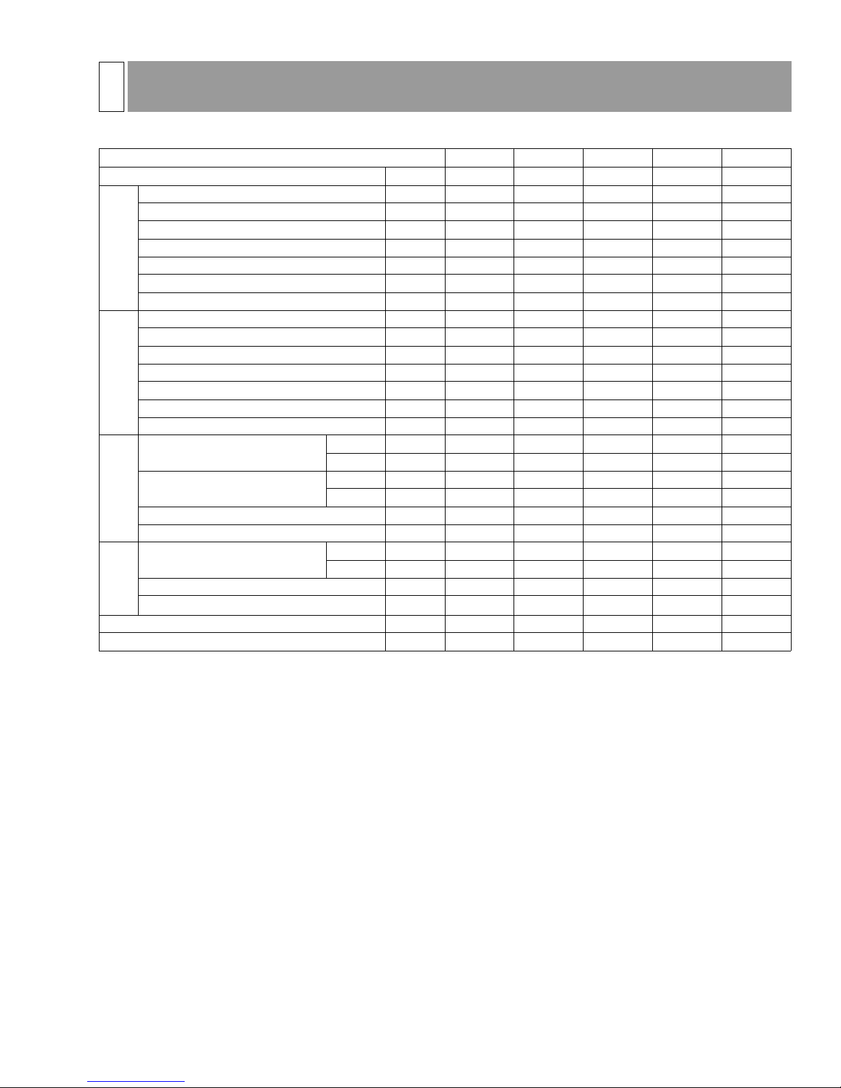
STANDARD OPERATING DATA
PL-AK INDOOR UNITS WITH PUG OUTDOOR UNITS
MODELS PL18AK PL24AK PL30AK PL36AK PL42AK
Item Unit Cooling Cooling Cooling Cooling Cooling
Voltage V 208/230 208/230 208/230 208/230 208/230
Frequency Hz 60 60 60 60 60
Total Input kW 1.82 2.38 2.85 3.34 4.35
Indoor Fan Current A 0.8 0.8 0.9 1.0 1.4
Booster Heater Current A -- -- -- -- -Outdoor Fan Current (FLA) A 0.5 0.5 0.5 1.4 1.4
Electrical Circuit
Compressor Current (230v) A 7.3 9.6 12.6 14.0 16.4
Condensing Pressure PSIG 223 270 283 280 267
Suction Pressure PSIG 84 85 80 82 71
Discharge Temperature °F 165 191 197 190 192
Condensing Temperature °F 91 112 108 111 104
Suction Temperature °F 60 58 59 62 50
Refrigerant Pipe Length FT 25 25 25 25 25
Refrigerant Circuit
Refrigerant Charge -- 3 lbs 14 oz 4 lbs 3 oz 4 lbs 2 oz 4 lbs 10 oz 5 lbs 3 oz
Intake Air Temperature
Discharge Air Temperature
Indoor Side
Fan Speed RPM. 1490 1490 1490 1490 1490
Airflow (High) CFM 710 990 1060 1060 710
Intake Air Temperature
Fan Speed RPM. 1050 1050 1050 1100 1100
Airflow (High) CFM 1785 1785 1835 2340 3320
Outdoor Side
Capacity BTU/H 20000 24000 28400 35600 41000
SHF --0.750.810.750.690.67
DB °F 80 80 80 80 80
WB °F 67 67 67 67 67
DB °F 59 58 59 59 59
WB °F 58 57 57 57 57
DB °F 95 95 95 95 95
WB °F -- -- -- -- --
Mitsubishi Electronics 2003 5
Page 6
036-21534-001 Rev. B (0703)
3
STANDARD OPERATING DATA
PC-GK INDOOR UNITS WITH PUG OUTDOOR UNITS
MODELS PC24GK PC30GK PC36GK PC42GK
Item Unit Cooling Cooling Cooling Cooling
Voltage V 208/230 208/230 208/230 208/230
Frequency Hz 60 60 60 60
Total Input kW 2.38 2.85 3.34 4.35
Indoor Fan Current A 0.8 0.9 1.0 1.4
Booster Heater Current A -- -- -- -Outdoor Fan Current (FLA) A 0.5 0.5 1.4 1.4
Electrical Circuit
Compressor Current (230v) A 9.6 12.6 14.0 16.7
Condensing Pressure PSIG 273 286 282 268
Suction Pressure PSIG 89 83 84 74
Discharge Temperature °F 191 196 190 191
Condensing Temperature °F 113 109 113 105
Suction Temperature °F 59 61 63 51
Refrigerant Pipe Length FT 25 25 25 25
Refrigerant Circuit
Refrigerant Charge -- 4 lbs 9 oz 4 lbs 9 oz 5 lbs 0 oz 5 lbs 10 oz
Intake Air Temperature
Discharge Air Temperature
Indoor Side
Fan Speed RPM 1490 1490 1490 1490
Airflow (High) CFM 880 1240 1240 1240
Intake Air Temperature
Fan Speed RPM 1050 1050 1100 1100
Airflow (High) CFM 1785 1835 2340 3320
Outdoor Side
Capacity BTU/H 24400 29800 36000 41500
SHF --0.750.780.720.71
DB °F 80 80 80 80
WB °F 67 67 67 67
DB °F 58 58 58 57
WB °F 56 57 57 56
DB °F 95 95 95 95
WB °F -- -- -- --
6 Mitsubishi Electronics 2003
Page 7
4
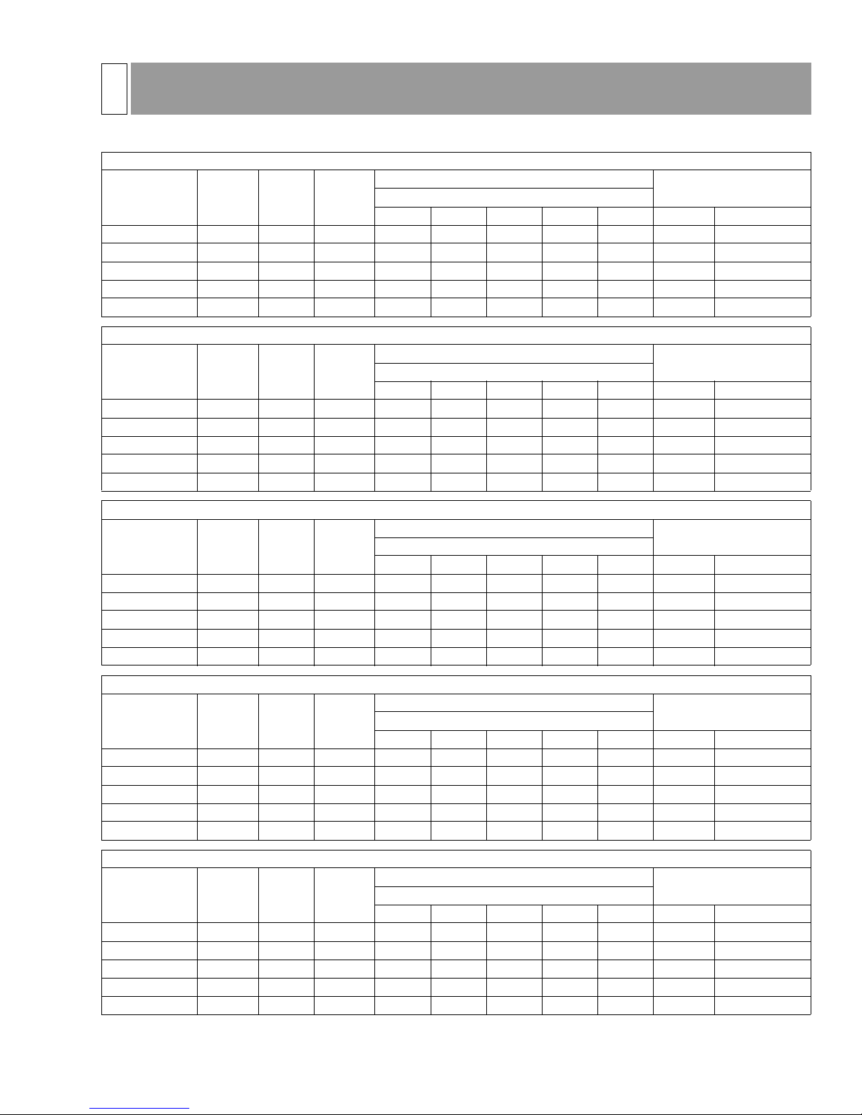
PERFORMANCE DATA - OPERATING PRESSURES
PK18+PUG18 (Indoor Air = 710 CFM)
75 °F Outdoor Air Temperature
Indoor Wet
Bulb (°F)
63 19,283 12.38 1,558 11,535 14,927 18,319 21,711 25,103 72 198
65 20,058 12.76 1,572 10,084 13,476 16,868 20,260 23,652 74 202
67 20,833 13.14 1,585 8,632 12,024 15,416 18,808 22,200 76 206
69 21,530 13.54 1,591 6,925 10,317 13,709 17,101 20,493 82 208
71 22,226 13.93 1,596 5,218 8,610 12,002 15,394 18,786 87 210
Indoor Wet
Bulb (°F)
63 18,401 11.02 1,670 11,047 14,439 17,831 21,223 24,615 76 231
65 19,259 11.42 1,687 9,720 13,112 16,504 19,896 23,288 78 234
67 20,117 11.81 1,704 8,393 11,785 15,177 18,569 21,961 81 238
69 20,812 12.15 1,712 6,612 10,004 13,396 16,788 20,180 85 239
71 21,508 12.50 1,721 4,830 8,222 11,614 15,006 18,398 89 241
Cooling
Capacity
(Btu/hr)
Cooling
Capacity
(Btu/hr)
EER
EER
Total
Power
(Watts)
Total
Power
(Watts)
Net Sensible Cooling Capacity (Btu/hr)
Indoor Dry Bulb (°F)
70 75 80 85 90 Suction Discharge
85 °F Outdoor Air Temperature
Net Sensible Cooling Capacity (Btu/hr)
Indoor Dry Bulb (°F)
70 75 80 85 90 Suction Discharge
036-21534-001 Rev. B (0703)
Pressures
(psig)
Pressures
(psig)
95 °F Outdoor Air Temperature
Indoor Wet
Bulb (°F)
63 17,518 9.83 1,782 10,559 13,951 17,343 20,735 24,127 80 263
65 18,459 10.24 1,802 9,356 12,748 16,140 19,532 22,924 83 266
67 19,400 10.65 1,822 8,154 11,546 14,938 18,330 21,722 85 269
69 20,095 10.96 1,834 6,298 9,690 13,082 16,474 19,866 88 271
71 20,789 11.26 1,846 4,442 7,834 11,226 14,618 18,010 90 272
Indoor Wet
Bulb (°F)
63 16,284 8.55 1,905 9,261 12,653 16,045 19,437 22,829 85 301
65 17,000 8.86 1,919 8,420 11,812 15,204 18,596 21,988 87 303
67 17,716 9.16 1,933 7,579 10,971 14,363 17,755 21,147 89 306
69 18,567 9.50 1,955 5,730 9,122 12,514 15,906 19,298 91 308
71 19,417 9.83 1,976 3,882 7,274 10,666 14,058 17,450 94 311
Indoor Wet
Bulb (°F)
63 15,049 7.42 2,028 7,964 11,356 14,748 18,140 21,532 90 339
65 15,541 7.63 2,037 7,484 10,876 14,268 17,660 21,052 91 341
67 16,032 7.84 2,045 7,004 10,396 13,788 17,180 20,572 92 342
69 17,039 8.21 2,075 5,162 8,554 11,946 15,338 18,730 95 346
71 18,045 8.57 2,106 3,321 6,713 10,105 13,497 16,889 98 350
Cooling
Capacity
(Btu/hr)
Cooling
Capacity
(Btu/hr)
Cooling
Capacity
(Btu/hr)
EER
EER
EER
Total
Power
(Watts)
Total
Power
(Watts)
Total
Power
(Watts)
Net Sensible Cooling Capacity (Btu/hr)
Indoor Dry Bulb (°F)
70 75 80 85 90 Suction Discharge
105 °F Outdoor Air Temperature
Net Sensible Cooling Capacity (Btu/hr)
Indoor Dry Bulb (°F)
70 75 80 85 90 Suction Discharge
115 °F Outdoor Air Temperature
Net Sensible Cooling Capacity (Btu/hr)
Indoor Dry Bulb (°F)
70 75 80 85 90 Suction Discharge
Pressures
Pressures
Pressures
(psig)
(psig)
(psig)
Mitsubishi Electronics 2003 7
Page 8

036-21534-001 Rev. B (0703)
4
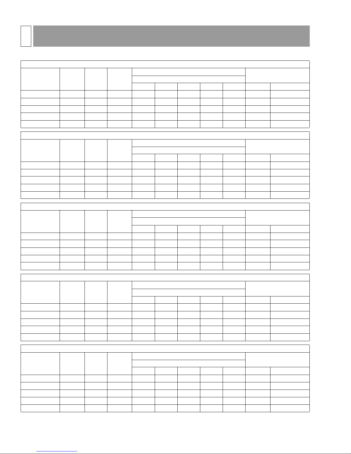
PERFORMANCE DATA - OPERATING PRESSURES
PK24+PUG24 (Indoor Air = 640 CFM)
75 °F Outdoor Air Temperature
Indoor Wet
Bulb (°F)
63 23,389 11.43 2,046 14,266 17,658 21,050 24,442 27,834 69 218
65 24,447 11.83 2,066 12,412 15,804 19,196 22,588 25,980 71 221
67 25,504 12.23 2,085 10,559 13,951 17,343 20,735 24,127 73 224
69 26,268 12.55 2,093 8,645 12,037 15,429 18,821 22,213 75 225
71 27,031 12.87 2,100 6,732 10,124 13,516 16,908 20,300 76 225
Indoor Wet
Bulb (°F)
63 21,933 10.13 2,166 13,570 16,962 20,354 23,746 27,138 73 250
65 23,193 10.54 2,201 11,882 15,274 18,608 22,058 25,450 76 254
67 24,452 10.93 2,237 10,194 13,586 16,978 20,370 23,762 80 257
69 25,272 11.24 2,247 8,291 11,683 15,017 18,467 21,859 80 258
71 26,092 11.55 2,258 6,388 9,780 13,172 16,564 19,956 81 259
Cooling
Capacity
(Btu/hr)
Cooling
Capacity
(Btu/hr)
EER
EER
Total
Power
(Watts)
Total
Power
(Watts)
Net Sensible Cooling Capacity (Btu/hr)
Indoor Dry Bulb (°F)
70 75 80 85 90 Suction Discharge
85 °F Outdoor Air Temperature
Net Sensible Cooling Capacity (Btu/hr)
Indoor Dry Bulb (°F)
70 75 80 85 90 Suction Discharge
Pressures
(psig)
Pressures
(psig)
95 °F Outdoor Air Temperature
Indoor Wet
Bulb (°F)
63 20,477 8.96 2,285 12,874 16,266 19,658 23,050 26,442 76 282
65 21,939 9.38 2,337 11,352 14,744 18,019 21,528 24,920 81 286
67 23,400 9.80 2,388 9,830 13,222 16,614 20,006 23,398 86 290
69 24,277 10.11 2,402 7,937 11,329 14,604 18,113 21,505 86 292
71 25,153 10.41 2,416 6,044 9,436 12,828 16,220 19,612 86 293
Indoor Wet
Bulb (°F)
63 18,736 7.72 2,426 11,542 14,934 18,326 21,718 25,110 80 321
65 20,005 8.11 2,467 10,266 13,658 16,992 20,442 23,834 84 322
67 21,274 8.49 2,507 8,990 12,382 15,774 19,166 22,558 87 323
69 22,428 8.85 2,533 7,226 10,618 13,952 17,402 20,794 89 326
71 23,582 9.22 2,558 5,463 8,855 12,247 15,639 19,031 90 329
Indoor Wet
Bulb (°F)
63 16,995 6.62 2,567 10,211 13,603 16,995 20,387 23,779 84 359
65 18,071 6.96 2,597 9,181 12,573 15,965 19,357 22,749 86 358
67 19,147 7.29 2,626 8,151 11,543 14,935 18,327 21,719 88 356
69 20,579 7.72 2,664 6,516 9,908 13,300 16,692 20,084 91 361
71 22,010 8.15 2,701 4,881 8,273 11,665 15,057 18,449 94 365
Cooling
Capacity
(Btu/hr)
Cooling
Capacity
(Btu/hr)
Cooling
Capacity
(Btu/hr)
EER
EER
EER
Total
Power
(Watts)
Total
Power
(Watts)
Total
Power
(Watts)
Net Sensible Cooling Capacity (Btu/hr)
Indoor Dry Bulb (°F)
70 75 80 85 90 Suction Discharge
105 °F Outdoor Air Temperature
Net Sensible Cooling Capacity (Btu/hr)
Indoor Dry Bulb (°F)
70 75 80 85 90 Suction Discharge
115 °F Outdoor Air Temperature
Net Sensible Cooling Capacity (Btu/hr)
Indoor Dry Bulb (°F)
70 75 80 85 90 Suction Discharge
Pressures
(psig)
Pressures
(psig)
Pressures
(psig)
8 Mitsubishi Electronics 2003
Page 9

4
PERFORMANCE DATA - OPERATING PRESSURES
PK30+PUG30 (Indoor Air = 990 CFM)
75 °F Outdoor Air Temperature
Indoor Wet
Bulb (°F)
63 29,702 12.28 2,419 18,029 21,421 26,138 30,855 34,247 72 224
65 30,517 12.57 2,428 15,612 19,004 23,721 28,438 31,830 73 225
67 31,331 12.85 2,438 13,196 16,588 21,305 26,022 29,414 74 225
69 32,153 13.08 2,458 10,787 14,179 18,896 23,613 27,005 76 228
71 32,974 13.31 2,477 8,378 11,770 16,487 21,204 24,596 78 230
Indoor Wet
Bulb (°F)
63 27,689 10.81 2,561 17,027 20,419 25,136 29,853 33,245 75 256
65 28,977 11.12 2,606 14,822 18,214 22,931 27,648 31,040 77 260
67 30,266 11.42 2,650 12,618 16,010 20,727 25,444 28,836 79 264
69 31,255 11.73 2,665 10,394 13,786 18,503 23,220 26,612 81 265
71 32,245 12.03 2,680 8,171 11,563 16,280 20,997 24,389 83 267
Cooling
Capacity
(Btu/hr)
Cooling
Capacity
(Btu/hr)
EER
EER
Total
Power
(Watts)
Total
Power
(Watts)
Net Sensible Cooling Capacity (Btu/hr)
Indoor Dry Bulb (°F)
70 75 80 85 90 Suction Discharge
85 °F Outdoor Air Temperature
Net Sensible Cooling Capacity (Btu/hr)
Indoor Dry Bulb (°F)
70 75 80 85 90 Suction Discharge
036-21534-001 Rev. B (0703)
Pressures
(psig)
Pressures
(psig)
95 °F Outdoor Air Temperature
Indoor Wet
Bulb (°F)
63 25,675 9.50 2,703 16,026 19,418 24,135 28,852 32,244 77 287
65 27,438 9.85 2,783 14,032 17,424 22,141 26,858 30,250 81 295
67 29,200 10.20 2,863 12,039 15,431 20,148 24,865 28,257 84 302
69 30,358 10.57 2,873 10,001 13,393 18,110 22,827 26,219 86 303
71 31,515 10.93 2,883 7,964 11,356 16,073 20,790 24,182 88.5 303
Indoor Wet
Bulb (°F)
63 23,599 8.95 2,635 14,612 18,004 22,721 27,438 30,830 81 326
65 25,183 8.95 2,813 12,912 16,304 21,021 25,738 29,130 83 331
67 26,768 8.95 2,991 11,212 14,604 19,321 24,038 27,430 86 337
69 28,268 9.31 3,035 9,213 12,605 17,322 22,039 25,431 89 339
71 29,769 9.67 3,078 7,213 10,605 15,322 20,039 23,431 92 342
Indoor Wet
Bulb (°F)
63 21,522 8.38 2,568 13,198 16,590 21,307 26,024 29,416 84 364
65 22,929 8.09 2,844 11,792 15,184 19,901 24,618 28,010 86 368
67 24,335 7.80 3,120 10,386 13,778 18,495 23,212 26,604 88 372
69 26,179 8.18 3,197 8,424 11,816 16,533 21,250 24,642 92 376
71 28,022 8.56 3,274 6,462 9,854 14,571 19,288 22,680 96 380
Cooling
Capacity
(Btu/hr)
Cooling
Capacity
(Btu/hr)
Cooling
Capacity
(Btu/hr)
EER
EER
EER
Total
Power
(Watts)
Total
Power
(Watts)
Total
Power
(Watts)
Net Sensible Cooling Capacity (Btu/hr)
Indoor Dry Bulb (°F)
70 75 80 85 90 Suction Discharge
105 °F Outdoor Air Temperature
Net Sensible Cooling Capacity (Btu/hr)
Indoor Dry Bulb (°F)
70 75 80 85 90 Suction Discharge
115 °F Outdoor Air Temperature
Net Sensible Cooling Capacity (Btu/hr)
Indoor Dry Bulb (°F)
70 75 80 85 90 Suction Discharge
Pressures
Pressures
Pressures
(psig)
(psig)
(psig)
Mitsubishi Electronics 2003 9
Page 10
036-21534-001 Rev. B (0703)
4
PERFORMANCE DATA - OPERATING PRESSURES
PK36+PUG36 (Indoor Air = 990 CFM)
75 °F Outdoor Air Temperature
Indoor Wet
Bulb (°F)
63 35,104 12.32 2,849 20,676 24,068 28,785 33,502 36,894 67 222
65 36,163 12.56 2,879 18,194 21,586 26,303 31,020 34,412 69 219
67 37,221 12.80 2,908 15,712 19,104 23,821 28,538 31,930 70 215
69 38,491 13.19 2,918 13,543 16,935 21,652 26,369 29,761 71 216
71 39,760 13.58 2,928 11,373 14,765 19,482 24,199 27,591 72 217
Indoor Wet
Bulb (°F)
63 32,861 10.90 3,014 19,756 23,148 27,865 32,582 35,974 70 249
65 34,286 11.17 3,068 17,336 20,728 25,445 30,162 33,554 72 249
67 35,711 11.44 3,122 14,917 18,309 23,026 27,743 31,135 74 250
69 36,865 11.74 3,140 12,719 16,111 20,828 25,545 28,937 75 251
71 38,020 12.04 3,158 10,521 13,913 18,630 23,347 26,739 77 252
Cooling
Capacity
(Btu/hr)
Cooling
Capacity
(Btu/hr)
EER
EER
Total
Power
(Watts)
Total
Power
(Watts)
Net Sensible Cooling Capacity (Btu/hr)
Indoor Dry Bulb (°F)
70 75 80 85 90 Suction Discharge
85 °F Outdoor Air Temperature
Net Sensible Cooling Capacity (Btu/hr)
Indoor Dry Bulb (°F)
70 75 80 85 90 Suction Discharge
Pressures
(psig)
Pressures
(psig)
95 °F Outdoor Air Temperature
Indoor Wet
Bulb (°F)
63 30,618 9.63 3,179 18,835 22,227 26,944 31,661 35,053 72 275
65 32,409 9.94 3,258 16,478 19,870 24,587 29,304 32,696 75 280
67 34,200 10.25 3,337 14,121 17,513 22,230 26,947 30,339 77 285
69 35,240 10.48 3,362 11,895 15,287 20,004 24,721 28,113 79 286
71 36,280 10.71 3,387 9,668 13,060 17,777 22,494 25,886 81 287
Indoor Wet
Bulb (°F)
63 27,936 8.32 3,358 17,359 20,751 25,468 30,185 33,577 76 314
65 29,667 8.63 3,438 15,258 18,650 23,367 28,084 31,476 79 318
67 31,398 8.93 3,518 13,158 16,550 21,267 25,984 29,376 83 323
69 32,844 9.21 3,565 11,006 14,398 19,115 23,832 27,224 84 324
71 34,290 9.49 3,612 8,855 12,247 16,964 21,681 25,073 86 326
Indoor Wet
Bulb (°F)
63 25,254 7.14 3,537 15,882 19,274 23,991 28,708 32,100 79 353
65 26,925 7.44 3,618 14,038 17,430 22,147 26,864 30,256 84 357
67 28,596 7.73 3,699 12,194 15,586 20,303 25,020 28,412 88 360
69 30,448 8.08 3,768 10,118 13,510 18,227 22,944 26,336 89 363
71 32,300 8.42 3,836 8,041 11,433 16,150 20,867 24,259 90 365
Cooling
Capacity
(Btu/hr)
Cooling
Capacity
(Btu/hr)
Cooling
Capacity
(Btu/hr)
EER
EER
EER
Total
Power
(Watts)
Total
Power
(Watts)
Total
Power
(Watts)
Net Sensible Cooling Capacity (Btu/hr)
Indoor Dry Bulb (°F)
70 75 80 85 90 Suction Discharge
105 °F Outdoor Air Temperature
Net Sensible Cooling Capacity (Btu/hr)
Indoor Dry Bulb (°F)
70 75 80 85 90 Suction Discharge
115 °F Outdoor Air Temperature
Net Sensible Cooling Capacity (Btu/hr)
Indoor Dry Bulb (°F)
70 75 80 85 90 Suction Discharge
Pressures
(psig)
Pressures
(psig)
Pressures
(psig)
10 Mitsubishi Electronics 2003
Page 11

4
PERFORMANCE DATA - OPERATING PRESSURES
PL18+PUG18 (Indoor Air = 600 CFM)
75 °F Outdoor Air Temperature
Indoor Wet
Bulb (°F)
63 19,879 12.21 1,629 11,583 14,989 18,395 21,801 25,207 71 200
65 20,894 12.72 1,643 10,125 13,532 16,938 20,344 23,750 73 204
67 21,477 12.95 1,658 8,668 12,074 15,480 18,886 22,293 75 208
69 22,451 13.50 1,663 6,954 10,360 13,766 17,172 20,578 81 210
71 22,913 13.73 1,668 5,240 8,646 12,052 15,458 18,864 86 212
Indoor Wet
Bulb (°F)
63 18,970 10.86 1,746 11,093 14,499 17,905 21,311 24,717 75 233
65 19,823 11.24 1,764 9,760 13,166 16,573 19,979 23,385 77 236
67 20,739 11.64 1,781 8,428 11,834 15,240 18,646 22,052 80 240
69 21,600 12.06 1,790 6,639 10,045 13,451 16,857 20,263 84 241
71 22,173 12.32 1,799 4,850 8,256 11,662 15,068 18,474 88 243
Cooling
Capacity
(Btu/hr)
Cooling
Capacity
(Btu/hr)
EER
EER
Total
Power
(Watts)
Total
Power
(Watts)
Net Sensible Cooling Capacity (Btu/hr)
Indoor Dry Bulb (°F)
70 75 80 85 90 Suction Disch.
85 °F Outdoor Air Temperature
Net Sensible Cooling Capacity (Btu/hr)
Indoor Dry Bulb (°F)
70 75 80 85 90 Suction Discharge
036-21534-001 Rev. B (0703)
Pressures
(psig)
Pressures
(psig)
95 °F Outdoor Air Temperature
Indoor Wet
Bulb (°F)
63 18,060 9.69 1,863 10,603 14,009 17,415 20,821 24,227 79 265
65 18,751 9.95 1,884 9,395 12,801 16,207 19,613 23,020 82 268
67 20,000 10.50 1,905 8,188 11,594 15,000 18,406 21,812 84 271
69 20,749 10.82 1,918 6,324 9,730 13,136 16,542 19,948 87 273
71 21,432 11.10 1,931 4,460 7,867 11,273 14,679 18,085 89 274
Indoor Wet
Bulb (°F)
63 16,787 8.43 1,992 9,300 12,706 16,112 19,518 22,924 84 303
65 17,098 8.52 2,007 8,455 11,861 15,267 18,673 22,079 86 305
67 18,264 9.03 2,022 7,610 11,016 14,422 17,828 21,235 88 308
69 19,169 9.38 2,044 5,754 9,160 12,566 15,972 19,378 90 310
71 20,018 9.69 2,066 3,898 7,304 10,710 14,116 17,522 93 313
Indoor Wet
Bulb (°F)
63 15,514 7.32 2,121 7,997 11,403 14,809 18,215 21,621 89 341
65 15,445 7.25 2,130 7,515 10,921 14,327 17,733 21,139 90 343
67 16,528 7.73 2,138 7,033 10,439 13,845 17,251 20,657 91 344
69 17,588 8.11 2,170 5,184 8,590 11,996 15,402 18,808 94 348
71 18,603 8.45 2,202 3,335 6,741 10,147 13,553 16,959 97 352
Cooling
Capacity
(Btu/hr)
Cooling
Capacity
(Btu/hr)
Cooling
Capacity
(Btu/hr)
EER
EER
EER
Total
Power
(Watts)
Total
Power
(Watts)
Total
Power
(Watts)
Net Sensible Cooling Capacity (Btu/hr)
Indoor Dry Bulb (°F)
70 75 80 85 90 Suction Discharge
105 °F Outdoor Air Temperature
Net Sensible Cooling Capacity (Btu/hr)
Indoor Dry Bulb (°F)
70 75 80 85 90 Suction Discharge
115 °F Outdoor Air Temperature
Net Sensible Cooling Capacity (Btu/hr)
Indoor Dry Bulb (°F)
70 75 80 85 90 Suction Discharge
Pressures
Pressures
Pressures
(psig)
(psig)
(psig)
Mitsubishi Electronics 2003 11
Page 12

036-21534-001 Rev. B (0703)
4
PERFORMANCE DATA - OPERATING PRESSURES
PL24+PUG24 (Indoor Air = 710 CFM)
95 °F Outdoor Air Temperature
Indoor Wet
Bulb (°F)
63 21,002 8.23 2,552 16,693 20,662 24,631 28,600 32,569 75 299
65 22,501 8.62 2,609 14,524 18,493 22,462 26,431 30,400 80 303
67 24,000 9.00 2,667 12,355 16,324 20,293 24,262 28,231 85 307
69 24,899 9.28 2,683 10,116 14,085 18,054 22,023 25,992 85 309
71 25,798 9.56 2,698 7,877 11,845 15,814 19,783 23,752 85 310
Indoor Wet
Bulb (°F)
63 19,216 7.09 2,710 15,878 19,847 23,816 27,785 31,754 79 338
65 20,518 7.45 2,755 13,903 17,872 21,841 25,810 29,779 83 320
67 21,819 7.79 2,800 11,928 15,897 19,866 23,835 27,804 87 302
69 23,003 8.13 2,829 9,701 13,670 17,639 21,608 25,577 88 324
71 24,186 8.46 2,857 7,474 11,443 15,412 19,381 23,350 89 346
Cooling
Capacity
(Btu/hr)
Cooling
Capacity
(Btu/hr)
EER
EER
Total
Power
(Watts)
Total
Power
(Watts)
Net Sensible Cooling Capacity (Btu/hr)
Indoor Dry Bulb (°F)
70 75 80 85 90 Suction Discharge
105 °F Outdoor Air Temperature
Net Sensible Cooling Capacity (Btu/hr)
Indoor Dry Bulb (°F)
70 75 80 85 90 Suction Discharge
Pressures
(psig)
Pressures
(psig)
115 °F Outdoor Air Temperature
Indoor Wet
Bulb (°F)
63 17,431 6.08 2,867 15,064 19,033 23,002 26,971 30,940 83 376
65 18,534 6.39 2,900 13,283 17,252 21,221 25,190 29,159 86 336
67 19,638 6.69 2,933 11,502 15,471 19,440 23,409 27,378 89 296
69 21,106 7.09 2,975 9,287 13,256 17,225 21,194 25,163 91 339
71 22,574 7.48 3,016 7,072 11,041 15,010 18,979 22,948 93 382
Indoor Wet
Bulb (F)
63 19,216 7.09 2,710 13,506 17,475 21,444 25,413 29,382 79 338
65 20,518 7.45 2,755 12,013 15,982 19,951 23,920 27,889 83 320
67 21,819 7.79 2,800 10,520 14,489 18,458 22,426 26,395 87 302
69 23,003 8.13 2,829 8,456 12,425 16,394 20,363 24,332 88 324
71 24,186 8.46 2,857 6,392 10,361 14,330 18,299 22,268 89 346
Indoor Wet
Bulb (F)
63 17,431 6.08 2,867 11,948 15,917 19,886 23,855 27,824 83 376
65 18,534 6.39 2,900 10,742 14,711 18,680 22,649 26,618 86 336
67 19,638 6.69 2,933 9,537 13,506 17,475 21,444 25,413 89 296
69 21,106 7.09 2,975 7,624 11,593 15,562 19,531 23,500 91 339
71 22,574 7.48 3,016 5,712 9,681 13,650 17,619 21,587 93 382
Cooling
Capacity
(Btu/hr)
Cooling
Capacity
(Btu/hr)
Cooling
Capacity
(Btu/hr)
EER
EER
EER
Total
Power
(Watts)
Total
Power
(Watts)
Total
Power
(Watts)
Net Sensible Cooling Capacity (Btu/hr)
Indoor Dry Bulb (°F)
70 75 80 85 90 Suction Discharge
105 F Outdoor Air Temperature
Net Sensible Cooling Capacity (Btu/Hr)
Indoor Dry Bulb ( F)
70 75 80 85 90 Suction Disch.
115 F Outdoor Air Temperature
Net Sensible Cooling Capacity (Btu/Hr)
Indoor Dry Bulb ( F)
70 75 80 85 90 Suction Disch.
Pressures
(psig)
Pressures
(psig)
Pressures
(psig)
12 Mitsubishi Electronics 2003
Page 13

4
PERFORMANCE DATA - OPERATING PRESSURES
PL30+PUG30 (Indoor Air = 1060 CFM)
75 °F Outdoor Air Temperature
Indoor Wet
Bulb (°F)
63 28,888 11.20 2,580 19,060 22,646 27,632 32,619 36,205 68 229
65 29,670 11.23 2,591 15,065 19,181 23,298 27,415 31,532 69 230
67 30,473 11.72 2,601 13,951 17,537 22,523 27,510 31,096 70 230
69 31,880 11.91 2,622 10,492 14,609 18,726 22,843 26,960 72 233
71 32,071 12.14 2,643 8,857 12,443 17,430 22,416 26,002 74 235
Indoor Wet
Bulb (°F)
63 26,930 9.86 2,732 18,001 21,587 26,573 31,560 35,146 70 261
65 28,148 10.13 2,779 15,670 19,256 24,242 29,229 32,815 72 265
67 29,436 10.41 2,827 13,339 16,925 21,912 26,898 30,484 75 269
69 30,672 10.79 2,843 10,988 14,574 19,561 24,548 28,134 77 270
71 31,361 10.97 2,859 8,638 12,224 17,211 22,197 25,783 79 272
Cooling
Capacity
(Btu/hr)
Cooling
Capacity
(Btu/hr)
EER
EER
Total
Power
(Watts)
Total
Power
(Watts)
Net Sensible Cooling Capacity (Btu/hr)
Indoor Dry Bulb (°F)
70 75 80 85 90 Suction Discharge
85 °F Outdoor Air Temperature
Net Sensible Cooling Capacity (Btu/hr)
Indoor Dry Bulb (°F)
70 75 80 85 90 Suction Discharge
036-21534-001 Rev. B (0703)
Pressures
(psig)
Pressures
(psig)
95 °F Outdoor Air Temperature
Indoor Wet
Bulb (°F)
63 24,972 8.66 2,883 16,942 20,528 25,514 30,501 34,087 73 292
65 26,626 8.97 2,968 13,778 17,894 21,869 26,128 30,245 76 300
67 28,400 9.30 3,054 12,727 16,313 21,300 26,287 29,873 80 307
69 29,464 9.61 3,065 9,633 13,750 17,725 21,983 26,100 82 308
71 30,652 9.97 3,076 8,419 12,005 16,992 21,978 25,564 84 308
Indoor Wet
Bulb (°F)
63 22,952 8.16 2,811 15,447 19,033 24,020 29,006 32,592 76 331
65 24,279 8.09 3,001 12,460 16,577 20,623 24,810 28,927 79 336
67 26,034 8.16 3,191 11,853 15,439 20,426 25,413 28,999 82 342
69 27,220 8.41 3,237 8,771 12,887 16,933 21,121 25,238 85 344
71 28,953 8.82 3,284 7,625 11,211 16,198 21,185 24,771 88 347
Indoor Wet
Bulb (°F)
63 20,932 7.64 2,740 13,952 17,538 22,525 27,512 31,098 80 369
65 21,932 6.60 3,034 11,143 15,259 19,376 23,493 27,610 82 373
67 23,668 7.11 3,328 10,979 14,565 19,552 24,539 28,125 84 377
69 24,976 7.33 3,410 7,908 12,025 16,142 20,259 24,375 88 381
71 27,254 7.80 3,492 6,832 10,418 15,405 20,391 23,977 92 385
Cooling
Capacity
(Btu/hr)
Cooling
Capacity
(Btu/hr)
Cooling
Capacity
(Btu/hr)
EER
EER
EER
Total
Power
(Watts)
Total
Power
(Watts)
Total
Power
(Watts)
Net Sensible Cooling Capacity (Btu/hr)
Indoor Dry Bulb (°F)
70 75 80 85 90 Suction Discharge
105 °F Outdoor Air Temperature
Net Sensible Cooling Capacity (Btu/hr)
Indoor Dry Bulb (°F)
70 75 80 85 90 Suction Discharge
115 °F Outdoor Air Temperature
Net Sensible Cooling Capacity (Btu/hr)
Indoor Dry Bulb (°F)
70 75 80 85 90 Suction Discharge
Pressures
Pressures
Pressures
(psig)
(psig)
(psig)
Mitsubishi Electronics 2003 13
Page 14

036-21534-001 Rev. B (0703)
4
PERFORMANCE DATA - OPERATING PRESSURES
PL36+PUG36 (Indoor Air = 1060 CFM)
75 °F Outdoor Air Temperature
Indoor Wet
Bulb (°F)
63 36,541 12.08 3,025 22,847 26,595 31,808 37,020 40,768 72 228
65 37,192 12.13 3,056 18,884 24,044 29,205 34,365 39,526 73 225
67 38,745 12.55 3,087 17,362 21,110 26,323 31,535 35,283 75 221
69 39,963 12.87 3,098 13,152 18,313 23,473 28,634 33,794 76 222
71 41,388 13.32 3,108 12,568 16,316 21,528 26,740 30,488 77 223
Indoor Wet
Bulb (°F)
63 34,206 10.69 3,200 21,830 25,578 30,790 36,002 39,751 74 255
65 35,284 10.83 3,257 19,156 22,904 28,117 33,329 37,077 77 255
67 37,172 11.21 3,315 16,483 20,231 25,443 30,656 34,404 79 256
69 38,448 11.53 3,334 14,054 17,802 23,015 28,227 31,975 80 257
71 39,576 11.81 3,352 11,625 15,374 20,586 25,798 29,546 81 258
Cooling
Capacity
(Btu/hr)
Cooling
Capacity
(Btu/hr)
EER
EER
Total
Power
(Watts)
Total
Power
(Watts)
Net Sensible Cooling Capacity (Btu/hr)
Indoor Dry Bulb (°F)
70 75 80 85 90 Suction Discharge
85 °F Outdoor Air Temperature
Net Sensible Cooling Capacity (Btu/hr)
Indoor Dry Bulb (°F)
70 75 80 85 90 Suction Discharge
Pressures
(psig)
Pressures
(psig)
95 °F Outdoor Air Temperature
Indoor Wet
Bulb (°F)
63 31,871 9.44 3,375 20,812 24,561 29,773 34,985 38,733 77 281
65 33,377 9.65 3,459 17,271 22,431 27,413 32,752 37,912 80 286
67 35,600 10.05 3,542 15,604 19,352 24,564 29,776 33,524 82 291
69 36,933 10.35 3,569 12,075 17,236 22,218 27,557 32,717 84 292
71 37,765 10.50 3,596 10,683 14,431 19,644 24,856 28,604 86 293
Indoor Wet
Bulb (°F)
63 29,080 8.16 3,565 19,181 22,929 28,141 33,354 37,102 80 320
65 30,435 8.34 3,650 15,619 20,779 25,851 31,100 36,261 84 324
67 32,683 8.75 3,735 14,539 18,287 23,499 28,712 32,460 88 329
69 34,120 9.02 3,785 10,994 16,155 21,226 26,476 31,636 89 330
71 35,694 9.31 3,834 9,784 13,532 18,745 23,957 27,705 90 332
Indoor Wet
Bulb (°F)
63 26,288 7.00 3,755 17,550 21,298 26,510 31,722 35,471 84 359
65 27,493 7.13 3,841 13,967 19,128 24,288 29,449 34,609 88 363
67 29,767 7.58 3,927 13,474 17,223 22,435 27,647 31,395 93 366
69 31,307 7.92 4,000 9,913 15,074 20,234 25,395 30,555 94 369
71 33,622 8.26 4,073 8,885 12,633 17,846 23,058 26,806 95 371
Cooling
Capacity
(Btu/hr)
Cooling
Capacity
(Btu/hr)
Cooling
Capacity
(Btu/hr)
EER
EER
EER
Total
Power
(Watts)
Total
Power
(Watts)
Total
Power
(Watts)
Net Sensible Cooling Capacity (Btu/hr)
Indoor Dry Bulb (°F)
70 75 80 85 90 Suction Discharge
105 °F Outdoor Air Temperature
Net Sensible Cooling Capacity (Btu/hr)
Indoor Dry Bulb (°F)
70 75 80 85 90 Suction Discharge
115 °F Outdoor Air Temperature
Net Sensible Cooling Capacity (Btu/hr)
Indoor Dry Bulb (°F)
70 75 80 85 90 Suction Discharge
Pressures
(psig)
Pressures
(psig)
Pressures
(psig)
14 Mitsubishi Electronics 2003
Page 15

4
PERFORMANCE DATA - OPERATING PRESSURES
PL42+PUG42 (Indoor Air = 1060 CFM)
75 °F Outdoor Air Temperature
Indoor Wet
Bulb (°F)
63 41,051 11.01 3,729 21,748 27,504 32,153 36,802 42,558 61 208
65 42,003 11.21 3,747 19,211 24,967 29,777 34,586 40,342 62 209
67 42,955 11.41 3,765 16,674 22,430 27,400 32,370 38,126 63 210
69 43,906 11.61 3,782 14,136 19,893 25,023 30,154 35,911 64 211
71 44,858 11.81 3,798 11,599 17,356 22,647 27,938 33,695 65 212
Indoor Wet
Bulb (°F)
63 40,028 10.04 3,986 21,614 27,371 31,811 36,252 42,009 65 239
65 40,990 10.23 4,007 19,015 24,772 29,447 34,122 39,878 66 240
67 41,977 10.24 4,099 16,417 22,173 27,082 31,992 37,748 67 241
69 42,913 10.61 4,045 13,818 19,574 24,718 29,861 35,618 68 242
71 43,875 10.80 4,063 11,219 16,975 22,353 27,731 33,487 69 244
Cooling
Capacity
(Btu/hr)
Cooling
Capacity
(Btu/hr)
EER
EER
Total
Power
(Watts)
Total
Power
(Watts)
Net Sensible Cooling Capacity (Btu/hr)
Indoor Dry Bulb (°F)
70 75 80 85 90 Suction Discharge
85 °F Outdoor Air Temperature
Net Sensible Cooling Capacity (Btu/hr)
Indoor Dry Bulb (°F)
70 75 80 85 90 Suction Discharge
036-21534-001 Rev. B (0703)
Pressures
(psig)
Pressures
(psig)
95 °F Outdoor Air Temperature
Indoor Wet
Bulb (°F)
63 39,004 9.19 4,244 21,481 27,237 31,470 35,703 41,459 69 270
65 39,976 9.37 4,266 18,820 24,577 29,117 33,658 39,414 70 271
67 41,000 9.25 4,432 16,160 21,916 26,765 31,613 37,369 71 273
69 41,920 9.73 4,308 13,499 19,255 24,412 29,568 35,325 72 274
71 42,892 9.91 4,328 10,839 16,595 22,059 27,523 33,280 74 275
Indoor Wet
Bulb (°F)
63 36,480 8.11 4,497 20,358 26,115 30,074 34,033 39,789 71 305
65 37,581 8.30 4,528 17,876 23,633 27,950 32,267 38,023 73 306
67 38,709 8.36 4,631 15,394 21,150 25,826 30,501 36,258 75 308
69 39,784 8.67 4,588 12,912 18,668 23,702 28,736 34,492 76 309
71 40,886 8.86 4,616 10,429 16,186 21,578 26,970 32,726 78 311
Indoor Wet
Bulb (°F)
63 33,955 7.15 4,749 19,236 24,993 28,678 32,362 38,119 74 340
65 35,186 7.35 4,790 16,932 22,689 26,782 30,876 36,632 76 342
67 36,417 7.54 4,830 14,628 20,385 24,887 29,389 35,146 78 343
69 37,649 7.74 4,867 12,324 18,081 22,992 27,903 33,659 80 345
71 38,880 7.93 4,903 10,020 15,776 21,096 26,416 32,173 83 346
Cooling
Capacity
(Btu/hr)
Cooling
Capacity
(Btu/hr)
Cooling
Capacity
(Btu/hr)
EER
EER
EER
Total
Power
(Watts)
Total
Power
(Watts)
Total
Power
(Watts)
Net Sensible Cooling Capacity (Btu/hr)
Indoor Dry Bulb (°F)
70 75 80 85 90 Suction Discharge
105 °F Outdoor Air Temperature
Net Sensible Cooling Capacity (Btu/hr)
Indoor Dry Bulb (°F)
70 75 80 85 90 Suction Discharge
115 °F Outdoor Air Temperature
Net Sensible Cooling Capacity (Btu/hr)
Indoor Dry Bulb (°F)
70 75 80 85 90 Suction Discharge
Pressures
Pressures
Pressures
(psig)
(psig)
(psig)
Mitsubishi Electronics 2003 15
Page 16

036-21534-001 Rev. B (0703)
4
PERFORMANCE DATA - OPERATING PRESSURES
PC24+PUG24 (Indoor Air = 830 CFM)
75 °F Outdoor Air Temperature
Indoor Wet
Bulb (°F)
63 24,389 10.91 2,236 15,714 19,450 23,186 26,923 30,659 72 236
65 25,491 11.29 2,258 13,672 17,408 21,144 24,881 28,617 80 266
67 26,594 11.67 2,279 11,630 15,366 19,103 22,839 26,575 89 296
69 27,390 11.97 2,287 9,522 13,259 16,995 20,731 24,467 84 270
71 28,186 12.28 2,295 7,415 11,151 14,887 18,623 22,360 79 243
Indoor Wet
Bulb (°F)
63 22,870 9.66 2,367 14,947 18,683 22,420 26,156 29,892 75 268
65 24,184 10.05 2,406 13,088 16,824 20,560 24,297 28,033 82 285
67 25,497 10.43 2,444 11,229 14,965 18,701 22,438 26,174 89 302
69 26,352 10.73 2,456 9,132 12,869 16,605 20,341 24,077 86 290
71 27,207 11.02 2,468 7,036 10,772 14,508 18,245 21,981 84 277
Cooling
Capacity
(Btu/hr)
Cooling
Capacity
(Btu/hr)
EER
EER
Total
Power
(Watts)
Total
Power
(Watts)
Net Sensible Cooling Capacity (Btu/hr)
Indoor Dry Bulb (°F)
70 75 80 85 90 Suction Discharge
85 °F Outdoor Air Temperature
Net Sensible Cooling Capacity (Btu/hr)
Indoor Dry Bulb (°F)
70 75 80 85 90 Suction Discharge
Pressures
(psig)
Pressures
(psig)
95 °F Outdoor Air Temperature
Indoor Wet
Bulb (°F)
63 21,352 8.55 2,498 14,180 17,917 21,653 25,389 29,125 79 300
65 22,876 8.96 2,554 12,504 16,240 19,976 23,713 27,449 84 304
67 24,400 9.35 2,610 10,828 14,564 18,300 22,036 25,772 89 308
69 25,314 9.64 2,625 8,742 12,479 16,215 19,951 23,687 89 310
71 26,228 9.93 2,641 6,657 10,394 14,130 17,866 21,602 89 311
Indoor Wet
Bulb (°F)
63 19,537 7.37 2,652 12,714 16,450 20,186 23,922 27,659 83 339
65 20,860 7.74 2,696 11,308 15,044 18,781 22,517 26,253 86 320
67 22,183 8.10 2,740 9,903 13,639 17,375 21,111 24,848 89 302
69 23,386 8.45 2,768 7,960 11,696 15,432 19,169 22,905 91 325
71 24,589 8.79 2,796 6,017 9,753 13,489 17,226 20,962 93 347
Indoor Wet
Bulb (°F)
63 17,721 6.32 2,806 11,247 14,983 18,720 22,456 26,192 87 377
65 18,843 6.64 2,838 10,113 13,849 17,585 21,321 25,057 88 337
67 19,965 6.96 2,871 8,978 12,714 16,450 20,186 23,923 89 296
69 21,458 7.37 2,911 7,177 10,913 14,650 18,386 22,122 93 340
71 22,951 7.78 2,952 5,377 9,113 12,849 16,585 20,322 97 383
Cooling
Capacity
(Btu/hr)
Cooling
Capacity
(Btu/hr)
Cooling
Capacity
(Btu/hr)
EER
EER
EER
Total
Power
(Watts)
Total
Power
(Watts)
Total
Power
(Watts)
Net Sensible Cooling Capacity (Btu/hr)
Indoor Dry Bulb (°F)
70 75 80 85 90 Suction Discharge
105 °F Outdoor Air Temperature
Net Sensible Cooling Capacity (Btu/hr)
Indoor Dry Bulb (°F)
70 75 80 85 90 Suction Discharge
115 °F Outdoor Air Temperature
Net Sensible Cooling Capacity (Btu/hr)
Indoor Dry Bulb (°F)
70 75 80 85 90 Suction Discharge
Pressures
(psig)
Pressures
(psig)
Pressures
(psig)
16 Mitsubishi Electronics 2003
Page 17

4
PERFORMANCE DATA - OPERATING PRESSURES
PC30+PUG30 (Indoor Air = 830 CFM)
75 °F Outdoor Air Temperature
Indoor Wet
Bulb (°F)
63 30,312 11.62 2,609 20,799 24,712 30,154 35,596 39,509 71 228
65 31,133 11.65 2,620 15,807 20,127 24,447 28,766 33,086 72 229
67 31,975 12.16 2,630 15,224 19,137 24,579 30,021 33,934 73 229
69 33,452 12.36 2,651 11,010 15,329 19,649 23,969 28,288 75 232
71 33,652 12.59 2,672 9,665 13,579 19,020 24,462 28,375 77 234
Indoor Wet
Bulb (°F)
63 28,257 10.23 2,762 19,644 23,557 28,999 34,440 38,354 74 260
65 29,536 10.51 2,811 17,100 21,013 26,455 31,897 35,810 76 264
67 30,887 10.80 2,859 14,556 18,470 23,911 29,353 33,266 78 268
69 32,184 11.19 2,875 11,991 15,905 21,346 26,788 30,701 80 269
71 32,907 11.38 2,891 9,426 13,340 18,781 24,223 28,136 82 271
Cooling
Capacity
(Btu/hr)
Cooling
Capacity
(Btu/hr)
EER
EER
Total
Power
(Watts)
Total
Power
(Watts)
Net Sensible Cooling Capacity (Btu/hr)
Indoor Dry Bulb (°F)
70 75 80 85 90 Suction Discharge
85 °F Outdoor Air Temperature
Net Sensible Cooling Capacity (Btu/hr)
Indoor Dry Bulb (°F)
70 75 80 85 90 Suction Discharge
036-21534-001 Rev. B (0703)
Pressures
(psig)
Pressures
(psig)
95 °F Outdoor Air Temperature
Indoor Wet
Bulb (°F)
63 26,203 8.99 2,915 18,488 22,401 27,843 33,285 37,198 76 291
65 27,939 9.31 3,002 14,457 18,776 22,947 27,416 31,736 80 299
67 29,800 9.65 3,088 13,889 17,802 23,244 28,686 32,599 83 306
69 30,916 9.98 3,099 10,108 14,428 18,598 23,067 27,387 85 307
71 32,163 10.34 3,110 9,187 13,101 18,542 23,984 27,897 88 307
Indoor Wet
Bulb (°F)
63 24,083 8.47 2,843 16,857 20,770 26,212 31,654 35,567 80 330
65 25,476 8.39 3,035 13,074 17,394 21,639 26,033 30,353 82 335
67 27,318 8.47 3,227 12,935 16,848 22,290 27,732 31,645 85 341
69 28,562 8.72 3,274 9,203 13,523 17,768 22,162 26,482 88 343
71 30,380 9.15 3,321 8,321 12,235 17,676 23,118 27,032 91 346
Indoor Wet
Bulb (°F)
63 21,964 7.93 2,770 15,226 19,139 24,581 30,023 33,936 83 368
65 23,013 6.85 3,068 11,692 16,012 20,331 24,651 28,971 85 372
67 24,835 7.38 3,365 11,981 15,895 21,337 26,778 30,692 87 376
69 26,207 7.60 3,448 8,298 12,618 16,938 21,257 25,577 91 380
71 28,598 8.10 3,531 7,455 11,369 16,811 22,252 26,166 95 384
Cooling
Capacity
(Btu/hr)
Cooling
Capacity
(Btu/hr)
Cooling
Capacity
(Btu/hr)
EER
EER
EER
Total
Power
(Watts)
Total
Power
(Watts)
Total
Power
(Watts)
Net Sensible Cooling Capacity (Btu/hr)
Indoor Dry Bulb (°F)
70 75 80 85 90 Suction Discharge
105 °F Outdoor Air Temperature
Net Sensible Cooling Capacity (Btu/hr)
Indoor Dry Bulb (°F)
70 75 80 85 90 Suction Discharge
115 °F Outdoor Air Temperature
Net Sensible Cooling Capacity (Btu/hr)
Indoor Dry Bulb (°F)
70 75 80 85 90 Suction Discharge
Pressures
Pressures
Pressures
(psig)
(psig)
(psig)
Mitsubishi Electronics 2003 17
Page 18

036-21534-001 Rev. B (0703)
4
PERFORMANCE DATA - OPERATING PRESSURES
PC36+PUG36 (Indoor Air = 1100 CFM)
75 °F Outdoor Air Temperature
Indoor Wet
Bulb (°F)
63 36,952 12.08 3,059 24,108 28,063 33,563 39,063 43,018 73 228
65 37,610 12.17 3,090 19,096 24,314 29,533 34,751 39,970 75 225
67 39,180 12.55 3,122 18,321 22,276 27,776 33,276 37,231 76 221
69 40,412 12.90 3,133 13,300 18,519 23,737 28,956 34,174 77 222
71 41,853 13.32 3,143 13,261 17,216 22,716 28,216 32,171 78 223
Indoor Wet
Bulb (°F)
63 34,591 10.69 3,236 23,035 26,990 32,490 37,990 41,945 76 255
65 35,681 10.83 3,294 20,214 24,169 29,669 35,169 39,124 78 255
67 37,590 11.21 3,352 17,393 21,348 26,848 32,348 36,303 80 256
69 38,880 11.53 3,371 14,830 18,785 24,285 29,785 33,740 81 257
71 40,021 11.81 3,390 12,267 16,222 21,722 27,222 31,177 83 258
Cooling
Capacity
(Btu/hr)
Cooling
Capacity
(Btu/hr)
EER
EER
Total
Power
(Watts)
Total
Power
(Watts)
Net Sensible Cooling Capacity (Btu/hr)
Indoor Dry Bulb (°F)
70 75 80 85 90 Suction Discharge
85 °F Outdoor Air Temperature
Net Sensible Cooling Capacity (Btu/hr)
Indoor Dry Bulb (°F)
70 75 80 85 90 Suction Discharge
Pressures
(psig)
Pressures
(psig)
95 °F Outdoor Air Temperature
Indoor Wet
Bulb (°F)
63 32,229 9.44 3,413 21,961 25,916 31,416 36,916 40,871 78 281
65 33,752 9.65 3,498 17,465 22,683 27,721 33,120 38,338 81 286
67 36,000 10.05 3,582 16,465 20,420 25,920 31,420 35,375 84 291
69 37,348 10.35 3,609 12,211 17,429 22,468 27,866 33,085 85 292
71 38,189 10.50 3,637 11,273 15,228 20,728 26,228 30,183 87 293
Indoor Wet
Bulb (°F)
63 29,406 8.16 3,605 20,240 24,195 29,695 35,195 39,150 82 320
65 30,777 8.34 3,691 15,794 21,013 26,141 31,450 36,668 85 324
67 33,051 8.75 3,777 15,342 19,297 24,797 30,297 34,252 89 329
69 34,504 9.02 3,827 11,118 16,336 21,465 26,773 31,992 90 330
71 36,095 9.31 3,878 10,324 14,279 19,779 25,279 29,234 92 332
Indoor Wet
Bulb (°F)
63 26,583 7.00 3,797 18,519 22,474 27,974 33,474 37,429 85 359
65 27,802 7.16 3,884 14,124 19,343 24,561 29,780 34,998 90 363
67 30,101 7.58 3,972 14,218 18,173 23,673 29,173 33,128 94 366
69 31,659 7.83 4,045 10,025 15,243 20,462 25,680 30,898 95 369
71 34,000 8.26 4,118 9,376 13,331 18,831 24,331 28,286 96 371
Cooling
Capacity
(Btu/hr)
Cooling
Capacity
(Btu/hr)
Cooling
Capacity
(Btu/hr)
EER
EER
EER
Total
Power
(Watts)
Total
Power
(Watts)
Total
Power
(Watts)
Net Sensible Cooling Capacity (Btu/hr)
Indoor Dry Bulb (°F)
70 75 80 85 90 Suction Discharge
105 °F Outdoor Air Temperature
Net Sensible Cooling Capacity (Btu/hr)
Indoor Dry Bulb (°F)
70 75 80 85 90 Suction Discharge
115 °F Outdoor Air Temperature
Net Sensible Cooling Capacity (Btu/hr)
Indoor Dry Bulb (°F)
70 75 80 85 90 Suction Discharge
Pressures
(psig)
Pressures
(psig)
Pressures
(psig)
18 Mitsubishi Electronics 2003
Page 19

4
PERFORMANCE DATA - OPERATING PRESSURES
PC42+PUG42 (Indoor Air = 1100 CFM)
75 °F Outdoor Air Temperature
Indoor Wet
Bulb (°F)
63 41,552 11.01 3,774 23,327 29,502 34,488 39,474 45,649 63 202
65 42,515 11.21 3,793 20,606 26,780 31,939 37,098 43,272 64 203
67 43,479 11.41 3,811 17,884 24,059 29,390 34,721 40,895 65 204
69 44,442 11.61 3,828 15,163 21,338 26,841 32,344 38,519 66 205
71 45,405 11.81 3,845 12,442 18,616 24,292 29,967 36,142 67 206
Indoor Wet
Bulb (°F)
63 40,516 10.04 4,035 23,184 29,359 34,122 38,885 45,060 67 233
65 41,490 10.23 4,056 20,396 26,571 31,585 36,600 42,774 69 234
67 42,489 10.39 4,089 17,609 23,783 29,049 34,315 40,489 71 235
69 43,437 10.61 4,094 14,821 20,996 26,513 32,030 38,204 71 236
71 44,410 10.80 4,113 12,034 18,208 23,976 29,745 35,919 72 238
Cooling
Capacity
(Btu/hr)
Cooling
Capacity
(Btu/hr)
EER
EER
Total
Power
(Watts)
Total
Power
(Watts)
Net Sensible Cooling Capacity (Btu/hr)
Indoor Dry Bulb (°F)
70 75 80 85 90 Suction Discharge
85 °F Outdoor Air Temperature
Net Sensible Cooling Capacity (Btu/hr)
Indoor Dry Bulb (°F)
70 75 80 85 90 Suction Discharge
036-21534-001 Rev. B (0703)
Pressures
(psig)
Pressures
(psig)
95 °F Outdoor Air Temperature
Indoor Wet
Bulb (°F)
63 39,480 9.19 4,296 23,041 29,215 33,755 38,296 44,470 71 264
65 40,464 9.37 4,318 20,187 26,361 31,232 36,102 42,277 72 265
67 41,500 9.50 4,368 17,333 23,508 28,708 33,909 40,083 74 267
69 42,431 9.73 4,361 14,479 20,654 26,185 31,716 37,890 75 268
71 43,415 9.91 4,381 11,626 17,800 23,661 29,522 35,697 76 269
Indoor Wet
Bulb (°F)
63 36,925 8.11 4,551 21,837 28,012 32,258 36,504 42,679 74 299
65 38,040 8.30 4,584 19,174 25,349 29,980 34,610 40,785 75 300
67 39,181 8.46 4,629 16,512 22,686 27,701 32,716 38,891 77 302
69 40,270 8.67 4,644 13,849 20,024 25,423 30,822 36,997 79 303
71 41,385 8.86 4,672 11,187 17,361 23,145 28,929 35,103 81 305
Indoor Wet
Bulb (°F)
63 34,369 7.15 4,807 20,633 26,808 30,760 34,713 40,887 76 334
65 35,615 7.35 4,849 18,162 24,336 28,727 33,118 39,293 78 336
67 36,862 7.54 4,889 15,691 21,865 26,694 31,524 37,698 81 337
69 38,108 7.74 4,927 13,219 19,394 24,661 29,929 36,104 83 339
71 39,354 7.93 4,963 10,748 16,922 22,629 28,335 34,509 85 340
Cooling
Capacity
(Btu/hr)
Cooling
Capacity
(Btu/hr)
Cooling
Capacity
(Btu/hr)
EER
EER
EER
Total
Power
(Watts)
Total
Power
(Watts)
Total
Power
(Watts)
Net Sensible Cooling Capacity (Btu/hr)
Indoor Dry Bulb (°F)
70 75 80 85 90 Suction Discharge
105 °F Outdoor Air Temperature
Net Sensible Cooling Capacity (Btu/hr)
Indoor Dry Bulb (°F)
70 75 80 85 90 Suction Discharge
115 °F Outdoor Air Temperature
Net Sensible Cooling Capacity (Btu/hr)
Indoor Dry Bulb (°F)
70 75 80 85 90 Suction Discharge
Pressures
Pressures
Pressures
(psig)
(psig)
(psig)
Mitsubishi Electronics 2003 19
Page 20

036-21534-001 Rev. B (0703)
C
B
A
5
DIMENSIONS AND CLEARANCES
Model A B C
PUG18AYB 17" (432 mm) 35" (889 mm) 23" (584 mm)
PUG24AYB 17" (432 mm) 35" (889 mm) 23" (584 mm)
PUG30AYB 19" (483 mm) 35" (889 mm) 23" (584 mm)
PUG36AYB 19" (483 mm) 35" (889 mm) 23" (584 mm)
PUG42AYB 27” (686 mm) 37” (940 mm) 27” (686 mm)
TYPICAL INSTALLATION
60” OVERHEAD
CLEARANCE
10” CLEARANCE
COIL AREA
NOTE: ALL OUTDOOR WIRING
MUST BE WEATHERPROOF.
MINIMUM 24” SERVICE ACCESS
CLEARANCE ON ONE SIDE
WEATHERPROOF
DISCONNECT
SWITCH
CONTROL ACCESS PANEL
NEC CLASS 1 WIRING
NEC CLASS 2 WIRING
TO INDOOR COIL
SEAL OPENING(S) WITH
PERMAGUM OR EQUIVALENT
20 Mitsubishi Electronics 2003
Page 21

6
OPERATING PRESSURES / SUPERHEAT
036-21534-001 Rev. B (0703)
SYSTEM CHARGE
The factory charge in the outdoor unit includes enough
charge for the unit and the smallest matched evaporator an d
25 feet of line. Some evaporator matches may require some
additional charge. See Tabular Data sheet provided in unit literature packet.
The “TOTAL SYSTEM CHARGE” must be permanently
stamped on the unit data plate.
Total system charge is determined as follows:
1. Determine outdoor unit charge for the selected evaporator from the corresponding table on Pages 4-6.
2. If using line length other than 25 feet, calculate the line
charge from the tables on Page 24.
NOTE: The line charge over 25 feet should be included on
the data plate and must be added to the system.
3. Total system charge = item 1 + item 2.
4. Permanently stamp the unit data plate with the total
amount of refrigerant in the system.
Use one of the following charging methods whenever additional refrigerant is required for the system charge.
MEASUREMENT METHOD
If a calibrated charging cylinder or accurate weighing device
is available, add refrigerant accordingly.
Compressor damage will occur if system is
improperly charged. On new system installations
charge system per R-22 charge information label
and follow guidelines in this instruction.
Check flare caps on service ports to be sure they
are leak tight. DO NOT OVER TIGHTEN
(between 40 and 60 inch - lbs. maximum).
SUPERHEAT CHARGING METHOD
NOTE: Use this method only during system maintenance
and repair.
1. Operate system until temperatures and pressures stabilize (minimum of 10 minutes).
2. Measure and record indoor wet bulb (WB) temperature
using a sling psychrometer and the outdoor dry bulb
(DB) temperature using a thermometer.
Refrigerant charging should only be carried out
by a qualified air conditioning contractor.
Table 1: SUPERHEAT VALUE
INDOOR WB
1
°F
50 9 7
52 12 10 6
54 14 12 10 7
56 17 15 14 10 6
58 20 18 16 13 9 5
60 23 21 19 16 12 8 6
62 26 24 22 19 16 12 8 5
64 29 27 24 21 18 15 11 9 6
66 32 31 30 24 23 18 15 11 9 6
68 35 33 30 27 24 21 19 16 14 12 9 6
70 35 33 30 28 25 22 20 18 15 13 11 8
72 35 33 30 28 26 24 20 20 17 15 14
74 34 31 30 27 25 23 22 20 18
76 35 33 31 29 27 26 25 23
1. Evaporator Entering Air °F
55 60 65 70 75 80 85 90 95 100 105 110 115
OUTDOOR DB°F
Mitsubishi Electronics 2003 21
Page 22

036-21534-001 Rev. B (0703)
6
OPERATING PRESSURES / SUPERHEAT
Table 2: TEMPERATURE AND PRESSURE
SUCTION
PRESSURE
PSIG
(Service Port)
61.5 353739414345474951535557596163656769
64.2 373941434547495153555759616365676971
67.1 394143454749515355575961636567697173
70.0 414345474951535557596163656769717375
73.0 434547495153555759616363676971737577
76.0 454749515355575961636567697173757779
79.2 474951535557596163656769717375777981
82.4 495153555759616365676971737577798183
1. Saturation Temperature
1
246810121416182022242628303234
0
SUCTION SERVICE VALVE SUPERHEAT
3. Measure and record the suction pressure at the suction
service valve port.
4. Using Table 1, note the superheat value correspondi ng
to the intersection of the indoor wet bulb and the outdoor
dry bulb.
5. With the superheat value obtained in step 4 and the suction pressure value from step 3, find the intersection of
the values in Table 2. This is the required suction tube
temperature at the suction service valve.
6. To bring the tube temperature in line with the required
value from Table 2, add refrigerant to the service port to
cause the tube temperature to fall and reclaim refrigerant
to cause the temperature to rise.
22 Mitsubishi Electronics 2003
Page 23

7
OPERATING RANGE
036-21534-001 Rev. B (0703)
1. POWER SUPPL Y
1 Phase 60 Hz 208/230 V
Normal Voltage Range: 187 to 252
FUNCTION
Cooling
1. A low ambient accessory kit is required for operation below this temperature which extends cooling operation to 25°.
CONDITION
Standard Temperature 80 67 97 75
Maximum Temperature 95 71 120 –
Minimum Temperature 67 57
Maximum Humidity 80 75 80 75
AIR INTAKE
DB (°F) WB (°F) DB (°F) WB (°F)
(Rated in accordance with ARI Standard 110, utilization
range “A”.
2. OPERATING TEMPERATURE RANGE
INDOOR OUTDOOR
55
1
–
Mitsubishi Electronics 2003 23
Page 24

036-21534-001 Rev. B (0703)
REFRIGERANT CHARGE (R-22 0Z.) ADJUSTMENT FOR
8
OPTIMUM PERFORMANCE
MODEL LIQUID OD VAPOR OD R-22 CHARGE, OZ/FT
PUG18, 24 3/8 5/8 0.14
PUG30, 36, 42 1/2 3/4 0.33
FACTORY CHARGE /
MODEL
PUG18 56 4 8 12
PUG24 54 4 8 12
PUG30 67 8 13 22
PUG36 63 8 15 23
PUG42 63 8 16 23
ARI RATING POINT
25 FT 40 FT 55 FT 70 FT
R-22 CHARGE, OZ
ADD CHARGE
24 Mitsubishi Electronics 2003
Page 25

036-21534-001 Rev. B (0703)
CAPACITY CORRECTION FACTORS FOR VARIOUS PIPE LENGTHS9
MODEL
PUG18AYB 1.0 0.982 0.966 0.947
PUG24AYB 1.0 0.976 0.951 0.926
PUG30AYB 1.0 0.988 0.976 0.964
PUG36AYB 1.0 0.983 0.964 0.946
PUG42AYB 1.0 0.991 0.982 0.973
Refrigerant piping length (one way)
25 ft 40 ft 55 ft 70 ft
Mitsubishi Electronics 2003 25
Page 26

036-21534-001 Rev. B (0703)
MICROPROCESSOR CONTROL10
1. COOLING/HEATING OPERATION
Outdoor unit operation is activated by delivery of a 12VDC signal from the indoor unit. Cooling o nly units have 2 low voltage
control wires from the indoor unit to the outdoor unit. The functions of these wires are:
• Wire #1: Common
• Wire #2: Initiates operation of the compressor and outdoor fan when 12VDC is supplied from the indoor unit.
2. OUTDOOR ABNORMALITY DETECTION BY INDOOR UNIT (P8 FAULT CODE)
A. The indoor unit constantly monitors the difference between return air temperature and indoor coil temperature. During
a call for cooling, if the indoor coil does not become at least nine degrees colder than the return air temperature after
approximately ten minutes of operation, the indoor circuit board will shut down the system. The indoor unit will display
the problem code “P8” at the indoor unit remote controller and terminate the 12VDC signal to the outdoor unit.
B. Th e “P8” code d oes not ne ce ssarily mean tha t the outdoor unit has a problem. It simply means that the indoor coil did
not become colder than the return air during a call for cooling.
C. If a “P8” code is displayed:
i. Turn the indoor remote controller off and back on to reset it.
ii. Set the remote controller to a “call” for cooling.
iii. At the indoor unit 12VDC control terminals, check to see if 12VDC is present on the #1 and #2 wires.
1. You may encounter a 3-minute delay in cooling before the 12VDC signal is generated or after the 12VDC signal
is delivered to the outdoor unit before the compressor contactor is energized.
iv.If 12VDC is present and the 3-minute delay has expired, the outdoor unit should be operating. If it is not, the indoor
unit is not the source of the problem and the following should be checked:
1. Check the 12VDC terminals at the outdoor unit for 12VDC. The pol arity must be the same as that o f the indoor.
That is, the control wires must be connected to matching numbered control terminations on the indoor and ou tdoor units (1 to 1, 2 to 2). If the wires are not connected properly, the unit will not be damaged, but it will not operate.
a. If no 12VDC signal is present when 12VDC is available at the indoor unit, check for a break/open in the control
wire.
b. If 12VDC is present, insure polarity is correct. If polarity is correct and a 12VDC sig nal is present, check the
LED indicators on the outdoor board.
i. Is the “Status” LED lit const antly? If so, the outdoor board is in time delay. Wait for it to expire (make sure the
12VDC signal is still available from the indoor unit).
ii. Is the “#2” LED lit? This indicates that the board is receiving 12VDC from the indoor unit.
NO LED: Recheck for 12VDC on the control wires, check for correct polarity and check the wires from the
terminal block to the board.
LED LIT: The board should be outputting 24 VAC to the compressor contactor and line voltage to the fan
(unless in low ambient control). Is the compressor/fan operating?
YES: System is OK
NO: Is the “Status LED” flashing?
NO: Bad outdoor board
YES: 2 Flash sequence indicates that the High Pressure Switch is open. 4 Flash sequence indicates that the
Low Pressure Safety Switch is open
3. OUTDOOR BOARD FUNCTIONALITY
A. High Pressure Safety Switch (HPSS). This switch opens at approximately 400 PSIG and closes at approximately
300 PSIG. There is no bypass on this switch. When the switch op ens, the control immediately stops the compressor
and outdoor fan. When the switch closes, the system can restart if the indoor unit has not entered a P8 fault code. If
the switch opens three times within a one-hour period, the out door unit operation is “locked out” and must be serviced.
Turning line voltage off and back on to the outdoor unit will reset the lockout. The indoor unit must also be reset to clear
the fault code. Turning the remote controller off and back on will reset the indoor unit.
B. Low Pressure Safety Switch (LPS). This switch opens at approximately 7 PSI and closes at approximately 22 PSI.
The switch is bypassed during the first 3 minutes of cooling operation. If the pr essure rises to the “cut in” point, the
compressor will restart if the delay has expired and the indoor unit is not in a P8 fault. If the switch opens 3 times within
a one-hour period, the outdoor unit will be “locked out” and must be serviced . Turning line voltage off and back on to
the outdoor unit will reset the lockout.
26 Mitsubishi Electronics 2003
Page 27

036-21534-001 Rev. B (0703)
MICROPROCESSOR CONTROL10
C. Low Ambient Temperature Switch (LATS). Th e purpose of this switch is to extend cooling operation in low outdoor
temperatures as low as 25°. The outdoor unit uses a high side pressure switch to cycle the fan. When pressure drops
to 165 PSI (+/-10), the switch opens and the fan stops. When pressure rises to 300 (+/- 10), the switch closes and the
fan restarts. A jumper is factory installed in place of the low ambient pressure switch. This jumper must be remo ved
when a low ambient accessory kit is in stalled.
During low ambient cooling operation the indoor unit may initiate an “air defrost” of the indoor coil once during every 16
minutes of continuous cooling operation. This insures that the coil has adequate airflow and should not be considered
as a fault.
D. Crankcase Heater (CCH) - A crankcase heater is installed into all PUG condensing units to protect the compressor
when operating under low ambient conditions. W hen line voltage is first applied to the outdoor unit, the control will
energize the crankcase heater. The control will continue to energize the CCH until the first call for compressor operation. The control never energizes the CCH during compressor opera tion. The con trol will ene rgize the CCH thirty minutes after the compressor turns off. It will then cycle the CCH on for 30 minutes and off for 30 minutes repeatedly until
the compressor is again turned on.
E. Compressor Contactor (CC) - The compressor contactor is energized with 24VAC when a 12 VDC is input to the out-
door unit on control wires 1 and 2 from the indoor unit. This 12 VDC signal is generated and sent from the indoor unit
on all calls for compressor operation.
F. Outdoor Fan Motor (ODF) - The outdoor fan motor typically operates at the same time as the compressor. Howe ver,
the fan may be off while the compressor is operating during low ambient cooling conditions as described previously.
G. Transformer Input (24VAC) - The secondary side of the transformer supplies 24 volts AC to the circuit board on the
“24VAC” terminals. This voltage operates the internal circuits of the board and also provides voltage to the compressor
contactor when appropriate. The primary side of the transformer is powered with line voltage from terminals marked
“L1” and “L2” on the board.
H. Line V oltage - Line voltage is input and output from the circuit board on the terminals marked “L1” and “L2”. There are
four terminals marked “L1”. These terminals provide “L1” input to the board and “L1” output to the transformer, crankcase heater and the outdoor fan motor.
There are two terminals marked “L2”. One terminal provides “L2” line voltage input to the board. The other provides
“L2” output to the transformer.
I. Anti-Recycle Delay Timer - The control provides an “anti-recycle delay” of three minutes in the cooling mode.
J. Time Shortening - Placing the defrost jumper to the “TEST” position shortens timings of the control to the following
values.
1. Anti-Recycle - 36 seconds
2. CCH Cycles - 24 seconds
3. Compressor Run - 1 second
4. Low Pressure Bypass - 12 seconds
K. Last Fault Memory Recall. The control maintains a memory of the last fault that occurred. The last fault code can be
recalled by moving the defrost jumper to the “TEST” positio n and observing the “STATUS” LED display. The control
stores only the last fault code. The control will reset the fault code memory when the line voltage to the outdoor unit is
turned off.
L. LED Function. The board has four LED’s which provide the following function:
1. “STATUS” LED indicate s normal operation or faults as follows:
LED FLASHES INDICATION OF CONDITION
Off Normal Operation, no fault, no “call”
Constant on LED
1 Flash Sequence Defrost Sensor Closed
2 Flash Sequence High Pressure Safety Switch Open
3 Flash Sequence LATS Open
4 Flash Sequence Low Pressure Safety Switch Open
2. “CCH” LED indicates that the crankcase heater is energized.
3. “2” LED indicates that the indoor unit is calling for compressor operation, 12VDC is present on control wire #2.
Mitsubishi Electronics 2003 27
Anti-recycle delay active. If the HPSS or LPS opens, the anti-recycle
will activate for 3 minutes before the fault can be displayed.
Page 28

036-21534-001 Rev. B (0703)
ELECTRICAL11
FIGURE 1: Wiring Diagram
28 Mitsubishi Electronics 2003
Page 29

036-21534-001 Rev. B (0703)
REFRIGERANT SYSTEM12
SERVICE PORTS
There are two service ports available to service technicians. One port is located at each of the two base valves.
A. Liquid Line Base Valve Service Port. This port is used to evacuate the refrigerant line set when the ball valve is in
the closed position. It may also be used to measure the liquid line pressure or, more accurately, the “saturated line”
pressure during normal operation. During cooling operation this servi ce port is downstream of the metering orifice
which is installed inside of the liquid line base valve body. While in the cooling mode this pressure is typically 25 to 40
PSI above that of the suction base valve pressure (usually 85 to 110 PSI).
B. Suction Base Valve Service Port. This port is also used to evacuate the indoor unit and line set during installation.
The ball valve must be closed to evacuate the line set and indoor unit. During normal cooling mode operation this pres-
sure port indicates evaporator pressure (minus line set pressure drop). Typical cooling mode pressure readings here
are in the range of 55 to 80 PSI during summer operation.
C. Both refrigerant lines must be insulated because th e “cooling side” metering device is loc ated in the ou tdoor
unit. Failure to insulate the liquid line, or more accurately the “saturation line”, will result in condensa te dripping from
the line and poor cooling performance.
D. Metering Devices. A fixed orifice that is located in the liquid base valve meters refrigerant in the cooling mode. If a
restriction or a compressor failure occurs this orifice can be easily accessed and cleaned after refrigerant is recovered.
It is important to use a back-up wrench on the liquid line base valve connections when accessing the orifice. Failure to
do so could loosen the base valve connections and cause a refrigerant leak.
OUTDOOR
COIL
COMPRESSOR
FIELD CONNECTION
LINE
FIELD CONNECTION
LINE
SUCTION
ACCUMULATOR
COOLING CYCLE FLOW
INDOOR COIL
Mitsubishi Electronics 2003 29
Page 30

036-21534-001 Rev. B (0703)
PARTS BREAKDOWN13
30 Mitsubishi Electronics 2003
Page 31

PARTS BREAKDOWN13
MODELS 18, 24, AND 30
ITEM DESCRIPTION PUG18AYB PUG24AYB PUG30AYB
1 Fan Guard (18”) 026-35511-018 026-35511-018 026-35511-018
2 Wireway 028-13215-000 028-13215-000 028-13215-000
3 Fan Motor 024-26067-010 024-26067-010 024-26067-010
4 Fan Blade 18” Diameter 026-34091-000 026-34091-000 026-34091-000
5 Top 2218-1021/A 2218-1021/A 2218-1021/A
6 Outdoor Coil Assembly 373-19800-001 373-19800-001 373-19800-002
7 Compressor
8 Compressor Mount (Pkg. of 4) 9435-1081 9435-1081 9435-1081
Dual Capacitor (25/5 MFD)
9
Dual Capacitor (30/5 MFD)
Dual Capacitor (35/5 MFD)
10 Contactor 024-27531-000 024-27531-000 024-27531-000
Base Valve 5/8”
11
Base Valve 3/4”
Base Valve 3/8” (.053 orifice)
12
Base Valve 3/8” (.059 orifice)
Base Valve 1/2” (.067 orifice)
13 Filter Drier 029-22156-000 029-22156-000 029-22156-000
14 Base Pan 2218-1011 2218-1011 2218-1011
15 Control Box Cover 2218-1151/A 2218-1151/A 2218-1151/A
16 Ground Lug 025-21798-000 025-21798-000 025-21798-000
17 Coil Guard 026-35413-000 026-35413-000 026-35414-000
18 Blockoff Plate 2218-1081/B 2218-1081/B 2236-1081/B
19 6 Position Plug 025-33306-006 025-33306-006 025-33306-006
20 Plastic Mesh, Coil Guard 028-14725-000 028-14725-000 028-14726-000
21 Kit, Motor Mounting (Acorn Nuts) 363-90117-700 363-90117-700 363-90117-700
22* Wiring Diagram 035-18738-001 035-18738-001 035-18738-001
23* Harness, Compressor 025-31883-000 025-31883-000 025-31883-000
24 Hubcap 026-39292-000 026-39292-000 026-39292-000
25 High Pressure Switch 025-33305-048 025-33305-048 025-33305-048
26 Low Pressure Switch 025-38610-000 025-38610-000 025-38610-000
27 Accumulator Tank 026-34089-000 026-34089-000 026-34089-000
28 Transformer 025-18452-000 025-18452-000 025-18452-000
29 Control Board 031-01976-000 031-01976-000 031-01976-000
30 Terminal Block 025-38589-002 025-38589-002 025-38589-002
015-03557-001
(H23B173ABCA)
024-23997-000
---
---
022-09048-625
---
022-09047-001
---
---
015-03558-001
(H23B223ABCA
---
024-24778-000
---
022-09048-625
---
---
022-09047-002
---
036-21534-001 Rev. B (0703)
015-03559-001
(H23B28SABCA)
---
---
024-25859-000
---
022-09049-750
---
---
022-09047-004
<
<
NOTE
*Not Shown
:
New replacement parts shown in bold face type at the first printing of parts list dated 4/
03.
Major components and suggested stocking items are shown with shaded item number.
“<“ Across from row indicates a change in that row.
--- Not applicable to specified model.
Mitsubishi Electronics 2003 31
Page 32

036-21534-001 Rev. B (0703)
PARTS BREAKDOWN13
MODELS 36 AND 42
ITEM DESCRIPTION PUG36AYB PUG42AYB
1
2 Wireway 028-13215-000 028-13216-000
3 Fan Motor 024-26020-000 024-27596-000
4
5 Top 2218-1021/A 2260-1021/A
6 Outdoor Coil Assembly 373-19800-002 373-19800-004
7 Compressor
8 Compressor Mount (Pkg. of 4)
9
10 Contactor (30 amp) 024-27531-000 024-27531-000
11 Base Valve 3/4” 022-09049-750 022-09049-750
12
13 Filter Drier 029-22156-000 029-22157-000
14 Base Pan 2218-1011 2260-1011
15 Control Box Cover 2218-1151/A 2218-1151/A
16 Ground Lug 025-21798-000 025-21798-000
17 Coil Guard 026-35414-000 026-35416-000
18 Blockoff Panel 2236-1081/B 2248-1081/B
19 6 Position Plug 025-33306-006 025-33306-006
20 Plastic Mesh, Coil Guard 028-14726-000 028-14728-000
21 Kit, Motor Mounting (Acorn Nut) 363-90117-700 363-90117-700
22* Wiring Diagram 035-15861-501 035-15861-501
23* Harness, Compressor 025-31883-000 025-31884-000
24 Hubcap 026-39292-000 026-39292-000
25 High Pressure Switch 025-33305-048 025-33305-048
26 Low Pressure Switch 025-38610-000 025-38610-000
27 Accumulator Tank 026-34089-000 026-34090-000
28 Transformer 025-18452-000 025-18452-000
29 Control Board 031-01976-000 031-01976-000
30 Terminal Block 025-38589-002 025-38589-002
Fan Guard (18”)
Fan Guard (22”)
Fan Blade 18” Diameter
Fan Blade 22” Diameter
Compressor Mount (4 Req’d)
Dual Capacitor (45/5 MFD)
Dual Capacitor (35/5 MFD)
Base Valve 1/2” (.071 orifice)
Base Valve 1/2” (.080 orifice)
026-35511-018
---
026-34092-000
---
015-03560-001
(H29B33UABCA)
9435-1081
---
024-25895-000
---
022-09047-005
---
---
026-35511-022
---
026-34593-000
015-02092-005
(H23A423ABCA)
9435-1081
---
---
024-25859-000
---
022-09047-006
<
<
NOTE
*Not Shown
:
New replacement parts shown in bold face type at the first printing of parts list dated 4/
03.
Major components and suggested stocking items are shown with shaded item number.
“<“ Across from row indicates a change in that row.
--- Not applicable to specified model.
32 Mitsubishi Electronics 2003
Page 33

036-21534-001 Rev. B (0703)
14
NOTES
Electrical Accessories
Part No. Description Used With
2LA08700324
TO ORDER AUTHORIZED FACTORY REPLACEMENT PARTS - Contact your local Mitsubishi Electric distributor. or visi t our
website at www.mrslim.com for a Distributor and Dealer listing.
Low Ambient Kit
(extends cooling operation to 25°)
All PUG Models
Mitsubishi Electronics 2003 33
Page 34

14 NOTES
Mitsubishi Electronics 2003 036-21534-001 Rev. B (0703)
Supersedes: 036-21534-001 Rev. A (0603)
Page 35

3400 Lawrenceville Suwanee Road ● Suwanee, Georgia 30024
Toll Free: 800-433-4822 ● Toll Free Fax: 800-889-9904
Specifications are subject to change without notice.
www.mrslim.com
 Loading...