

Page 1
AIR CONDITIONERS CITY MULTI
Models < Outdoor unit >
PUD-P250YMF-C
< Iutdoor unit >
PFD-P250VM-A
PFD-P500VM-A
Service Handbook
Service Handbook PUD-P250YMF-C
PFD-P250VM-A
PFD-P500VM-A
Issued in Jun. 2004 MEE03K207-A
Printed in Japan
New publication effective Jun.2004
Specifications subject to change without notice.
HEAD OFFICE: MITSUBISHI DENKI BLDG., 2-2-3, MARUNOUCHI, CHIYODA-KU, TOKYO 100-8310, JAPAN
Service Handbook Close Control PUD-P250YMF-C/PFD-P250, P500VM-A
Page 2

- 1 -
Contents
Please Read Before Servicing the Unit
1 Check Before Servicing the Unit .................................................. 8
[1]
Find out the model type and refrigerant type of the unit to be serviced
.. 8
[2] Principal System Components .............................................. 8
[3] Check the symptoms of the unit requiring service ................ 9
[4]
Be sure to read Read Before Servicing at the beginning of this manual
.. 9
[5] Prepare necessary tools ........................................................ 9
[6] If the refrigerant circuit is opened (to repair gas leak etc.),
the drier needs to be replaced .............................................. 9
[7]
Preparing the connecting pipes: When relocating or replacing
the unit, find out what types of refrigerant is used for the unit
.... 9
[8]
If there is a gas leak or if the remaining refrigerant is exposed to an open flame,
a noxious gas hydrofluoric acid may form. Provide adequate ventilation
.......... 9
2 Necessary Tools and Materials.................................................... 10
[1]
List of Tools and Materials Necessary for Units that Use R407C
(and adaptability of tools that have been used with units that use R22)
...... 10
3 Piping Materials .......................................................................... 11
4 Storage of Piping Materials.......................................................... 12
[1] Storage Location .................................................................... 12
[2] Pipe sealing before storage.................................................... 12
5 Machining Pipes .......................................................................... 13
6 Brazing ........................................................................................ 14
7 Testing Air Tightness.................................................................... 15
8 Vacuum Drying (Evacuating) ...................................................... 16
9 Charging the Circuit with Refrigerant .......................................... 17
0 What to Do When Refrigerant Leaks .......................................... 19
A Replacing the Drier ...................................................................... 19
11
. Restrictions
1 System Restrictions and System Configuration .......................... 20
[1] Switch Setting ........................................................................ 20
2 Restrictions on Transmission Lines.............................................. 22
[1] Electrical Wiring ...................................................................... 22
3 Restrictions on Refrigerant Pipe Length ...................................... 38
[1] Refrigerant Piping .................................................................. 38
22
. Components of the Unit
1 Internal Structure ........................................................................ 39
2 Control Box .................................................................................. 42
3 Main Board .................................................................................. 44
33
. Electrical Wiring Diagrams
1 Outdoor Unit ................................................................................ 49
2 Indoor Unit.................................................................................... 50
44
. Refrigerant Circuit
1 Refrigerant Circuit Diagram ........................................................ 52
2 List of Major Component Functions ............................................ 53
Page 3

- 2 -
55
. Control
1 Dip Switch Functions and Factory Settings ................................ 56
[1] Outdoor Unit .......................................................................... 56
[2] Indoor Unit .............................................................................. 57
2 Controlling the Outdoor Unit ........................................................ 58
[1] Initial Control .......................................................................... 58
[2] Control at startup .................................................................... 58
[3] Bypass control ........................................................................ 58
[4] Frequency Control .................................................................. 59
[5] Oil-Return Control .................................................................. 60
[6] Outdoor Unit Fan .................................................................... 60
[7] Subcool Coil Control (Linear Expansion Valve (LEV1)).......... 60
[8] Circulating composition sensor (CS circuit)............................ 60
[9] Emergency Operation Mode .................................................. 61
[10]
Capacity Control Between Outdoor Units (For P500 Type Only)
.. 61
[11] Control-Block Diagram.......................................................... 62
[12] Operation Modes .................................................................. 62
3 Controlling the Indoor Unit .......................................................... 63
[1] Thermostat Functions ............................................................ 63
[2] Actuator Control...................................................................... 64
[3] Temperature Setting Range.................................................... 64
[4] Emergency Operation Mode .................................................. 64
[5] Three-minute restart-suspension mode.................................. 65
[6] Anti-Freeze Control ................................................................ 65
[7] Operation during Electrical Power Failure .............................. 65
4 Operation Flow Chart .................................................................. 66
[1] Mode Selection Flow Chart .................................................... 66
[2] Operation in each Mode ........................................................ 68
66
. Refrigerant Amount Adjustment
1 Operating Characteristics and Refrigerant Amount .................... 69
[1] Operating Characteristics/Refrigerant Amount ...................... 69
2 Checking and Adjusting Refrigerant Amount .............................. 69
[1] Symptoms .............................................................................. 69
[2] Refrigerant Volume ................................................................ 69
[3] Amount of Refrigerant to Be Added ...................................... 70
3 Refrigerant-Adjustment Operation Mode .................................... 71
[1] Procedures (only for air-cooled outdoor units) ...................... 71
77
. Troubleshooting
1 List of Check Code ...................................................................... 73
2 Intermittent Fault Check Code (outdoor units only) .................... 74
3 Self-Diagnosis and Problem-Solving Using Check Codes .......... 75
[1] Mechanical.............................................................................. 75
[2] Communication / System........................................................ 86
[3] System error .......................................................................... 93
[4] Troubleshooting using information on problems
with Remote Control, Input from External Source ................ 95
4 Transmission Wave Pattern and Noise Check ............................ 99
[1] M-NET Transmission .............................................................. 99
[2] MA Remote Controller Transmission ...................................... 100
5 Troubleshooting............................................................................ 102
[1] Principal Parts ........................................................................ 102
Page 4

- 3 -
88
. LED Monitor Display
1 How to Read the Service Monitor LED........................................ 115
[1] How to read the LED .............................................................. 115
[2] Outdoor Unit Control LED Monitor.......................................... 116
99
. Test Run
1 Before a Test Run ........................................................................ 124
2 Test-Run Method.......................................................................... 124
3 Not to Be Alarmed When the Following Symptoms Appear........ 125
4 Standard Operation (reference data) .......................................... 126
[1] Cooling Operation .................................................................. 126
[2] Operation under Other Conditions.......................................... 126
00
. When Refrigerant Leaks
1 Repairing Leaks: Preparation, making repairs, and recharging
the system with refrigerant .......................................................... 127
[1] Location of leaks: Extension piping or indoor unit.................. 127
[2] Location of leaks: Outdoor unit .............................................. 127
0011
. Circulating Composition Analysis
1 Check the Composition of the Refrigerant .................................. 128
Page 5
- 4 -
Warning
Safety Precautions
Warning: Failure to follow all instructions may result in serious personal injury or death.
Caution: Failure to follow all instructions may result in personal injury or damage to the unit.
sAfter reading this handbook, hand it over to those who will be using the unit.
sThe user of the unit should keep this manual at hand and make it available to those who will be
performing repairs, to those who will be relocating the unit, and to new users.
Have the unit professionally installed.
• Improper installation by an unqualified person may result in
water leak, electric shock, or fire.
Only use specified cables for wiring. Securely connect
each cable, and make sure that the cables are not
straining the terminals.
• Cables not connected securely and properly may generate
heat and cause fire.
Do not make any changes or modifications to the unit. In
case of problems, consult the dealer.
• Inadequate repairs may result in water leak, electric shock,
or file.
Only use Refrigerant R407C.
• The use of any other refrigerant or the introduction of air
into the unit circuit may damage the unit.
Have all electrical work performed by a licensed
electrician according to the local regulations and the
instructions given in this manual.
Secure a circuit designated exclusively to the unit.
• Improper installation or a lack of circuit capacity at the
power source presents a risk of electric shock or fire.
Be sure to carefully follow each step in this handbook
when installing the unit.
• Improper installation may result in water leak, electric
shock, or fire.
Securely attach the terminal cover (panel) on the unit.
• If installed improperly, dust and/or water may enter the unit
and fire or electric shock may result.
When relocating the air conditioner, consult the dealer or
a specialist.
• Improper installation may result in water leak, electric
shock, or fire.
After completing service work, check for refrigerant gas
leaks.
• If leaked refrigerant gas is exposed to a heart source, such
as fan heater, stove, and electric grill, noxious gases may
form.
Only use specified parts, and have the unit professionally
installed.
• Improper installation may result in water leak, electric
shock, or fire.
When installing the unit in a small room, safeguard
against hypoxia, which is caused by the leaked refrigerant
exceeding the threshold level.
• Consult the dealer for necessary measures to take.
When a gas leak is detected, provide adequate ventilation
to the room.
• If leaked refrigerant gas is exposed to a heat source,
noxious gases may form.
Do not try to defeat the safety features of the devices, and
do not change the settings.
• Defeating the safety features such as the ones on pressure
switch and temperature switch or using parts other than
those specified by Mitsubishi Electric may result in fire or
explosion.
Place the unit on a stable, level surface that will withstand
the weight of the unit to prevent the unit from toppling
over.
Take necessary safety measures against typhoons and
earthquakes to prevent the unit from toppling over.
Do not touch the fins on the heat exchanger with bare
hands: they are sharp and dangerous.
sBefore installing the unit, be sure to read all the “Safety Precautions” very carefully.
sThey provide very important information regarding safety. Be sure to take these precautions to ensure safety.
Page 6
- 5 -
Caution
Precautions for Devices that Use R407C Refrigerant
Do not use existing refrigerant piping.
• The old refrigerant and refrigerator oil in the existing piping
contain a large amount of chlorine, which will deteriorate
the refrigerator oil in the new unit.
Use refrigerant pipes made of C1220 phosphorus
deoxidized copper categorized under H3000 (Copper and
Copper Alloy Seamless Pipes and Tubes), a standard set
by JIS.
• Keep inner and outer surfaces of the pipes clean and free
of contaminants, such as sulfur, oxides, dust/dirt, shaving
particles, oils, and moisture. Contaminants inside the
refrigerant piping will deteriorate the refrigerant oil.
Store the piping to be used during installation indoors,
and keep both ends of the piping sealed until immediately
before brazing. (Keep elbows and other joints wrapped in
plastic.)
• If dust, dirt, or water enters the refrigerant circuit,
deterioration of the oil or compressor problems may result.
Use a small amount of ester oil, ether oil, or alkylbenzene
to coat flares and flange connections.
• Refrigerator oil will deteriorate if it is mixed with a large
amount of mineral oil.
Be especially careful when managing tools.
• Exercise caution so that tools do not introduce dust, dirt,
and water into the refrigerant cycle.
Use liquid refrigerant to charge the circuit.
• Charging the unit with gas refrigerant will cause the
refrigerant in the cylinder to change its composition and will
lead to a drop in performance.
Only use R407C refrigerant.
• The use of other refrigerants containing chlorine (i.e. R22)
will deteriorate the refrigerant.
Do not use the following tools that have been used with
the existing refrigerators.
(Gauge manifold, charge hose, gas-leak detector, reverseflow-check valve, refrigerant charge base, vacuum gauge,
and refrigerant recovery equipment.)
• If refrigerant and / or refrigerant oil left on these tools are
mixed in with R407 or if water is mixed with R407C
refrigerant, the refrigerant will deteriorate.
• Since R407C does not contain chlorine, gas-leak detectors
for conventional refrigerators will not work.
Do not use a charging cylinder.
• The use of charging cylinder will change the composition of
the refrigerant and lead to power loss.
Use a vacuum pump with a reverse-flow-check valve.
• If other types of valves are used, the vacuum pump oil will
flow back into the refrigerant circuit and deteriorate the
refrigerator oil.
Page 7
- 6 -
Caution
Before Installing the Unit
Do not use the unit to preserve food, animals, plants, or
artifacts, or for other special purposes.
• The unit is not designed to provide adequate conditions to
preserve the quality of these items.
Use a closed circulating water circuit (which does not
release water in the air) as a heat source.
Do not install the unit in a place where there is a
possibility of flammable gas leak.
• Leaked gas accumulated around the unit may start a fire.
Do not use the unit in an unusual environment.
• Installing the unit in a place where a large amount of oil,
steam, or sulphurous gas is present may lead to a
remarkable drop in performance and/or damage to the unit.
Ground the unit.
• Do not connect the grounding on the unit to the grounding
terminals of gas pipes, water pipes, lightning rods, or
telephones. Improper grounding presents a risk of electric
shock.
Heat-Source Unit is only to be installed indoors (including
mechanical rooms). Make sure that the temperature
around the heat-source unit does not exceed 40˚CDB and
that it is out of direct sunlight.
• A sharp rise in the temperature inside the unit may damage
the unit.
When installing draining pipes, follow the instructions in
the manual and make sure that they properly drain water
as to prevent dew condensation.
• If not installed properly, water may leak and damage the
furnishings.
Make sure that the quality of circulating water meets the
standards set by Mitsubishi based on the Guidelines for
the Quality of Water for Refrigeration and Air Conditioning
established by the Japan Refrigeration and Air
Conditioning Industry Association.
• Using low-quality water may result in decreased
performance of the water-heat exchanger or corrosion.
Do not place the unit on or over things that should not get
wet.
• When humidity level exceeds 80% or when the drainage
system is clogged, indoor units may drip water. Installation
of a centralized drainage system for the heat-source unit
may also need to be considered to prevent water drips.
When installing the unit in hospitals, take necessary
measures against noise interference.
• High-frequency medical devices may interfere with the
normal operation of the air conditioning unit or vice versa.
• Water in an open circulating water circuit may become
contaminated when exposed to air and lead to a drop in
water-heat exchanger performance. It may also corrode the
exchanger.
Use breakers and fuses with proper current capacity. Do
not use large-capacity fuses, steel wire, or copper wire,
for they may damage the unit or cause fire.
For electrical wiring, use standard wires with proper
current capacity to prevent electric leak, overheating, and
fire.
Caution
Before Installing (Relocating) the Unit or Performing Electrical Work
Make sure the wires are not subject to tension.
• If the wires are too taut, they may generate heat and cause
fire.
Install a leak breaker at the power source to avoid the risk
of electric shock.
Do not spray water on air conditioners. Spraying the unit
presents a risk of electric shock.
Periodically check the platform on which the unit is placed
for damage to prevent the unit from toppling over.
Page 8
- 7 -
Caution
Before Installing (Relocating) the Unit or Performing Electrical Work
Turn on the unit at least 12 hours before the test run, and
keep the unit on throughout the season.
• If the unit is turned off during the season, problems may
occur.
Do not turn off the power immediately after stopping the
unit.
• Wait for at least five minutes; otherwise, the unit may leak
water or experience other problems.
Do not touch refrigerant piping with bare hands during
and immediately after operation.
• Depending on the state of the refrigerant in the system,
refrigerator parts such as piping and compressor may
become very hot or cold and may subject the person to
frost bites or burning.
Do not operate the unit without panels and safety guards
in their proper places.
• They are provided to keep the users from injury from
accidentally touching rotating, high-temperature, or highvoltage parts.
Properly dispose of packing materials.
• Things such as nails and wood pieces may be included in
the package. Dispose of them properly to prevent injury.
• Plastic bags present a choking hazard to children. Tear up
the plastic bags before disposing of them to prevent
accidents.
Exercise caution when transporting products.
• Do not try to move equipments over 20kg (approx. 44 lbs.)
alone.
• Do not use the PP bands used on some packages for
transportation.
• Wear protective gloves to avoid injury caused by coming in
contact with the fins on the heat exchanger.
• When using suspension bolt to transport heat-source unit,
use four-point suspension. Three-point suspension does
not provide adequate stability and presents a risk of injury.
Caution
Before the Test Run
To prevent the risk of electric shock, do not operate
switches with wet hands.
Do not operate the unit without air filters.
• Dust particles in the air may clog the system.
Page 9
- 8 -
Please Read Before Servicing the Unit
11
Check Before Servicing the Unit
[1] Find out the model type and refrigerant type of the unit to be serviced.
[2] Principal System Components
PUD-P250YMF-C
10HP(downward flow): PFD-P250VM-A(-H)
20HP(downward flow): PFD-P500VM-A(-H)
✻
'-H' in the indoor units indicates that the unit pipes come out of the top of the unit (50/60Hz, fit to order).
✻
PFD-type indoor units cannot be connected to outdoor units other than the ones specified above.
✻
PFD-type indoor units and other types of indoor units cannot coexist in the same refrigerant system.
} Outdoor Unit
} Indoor Unit
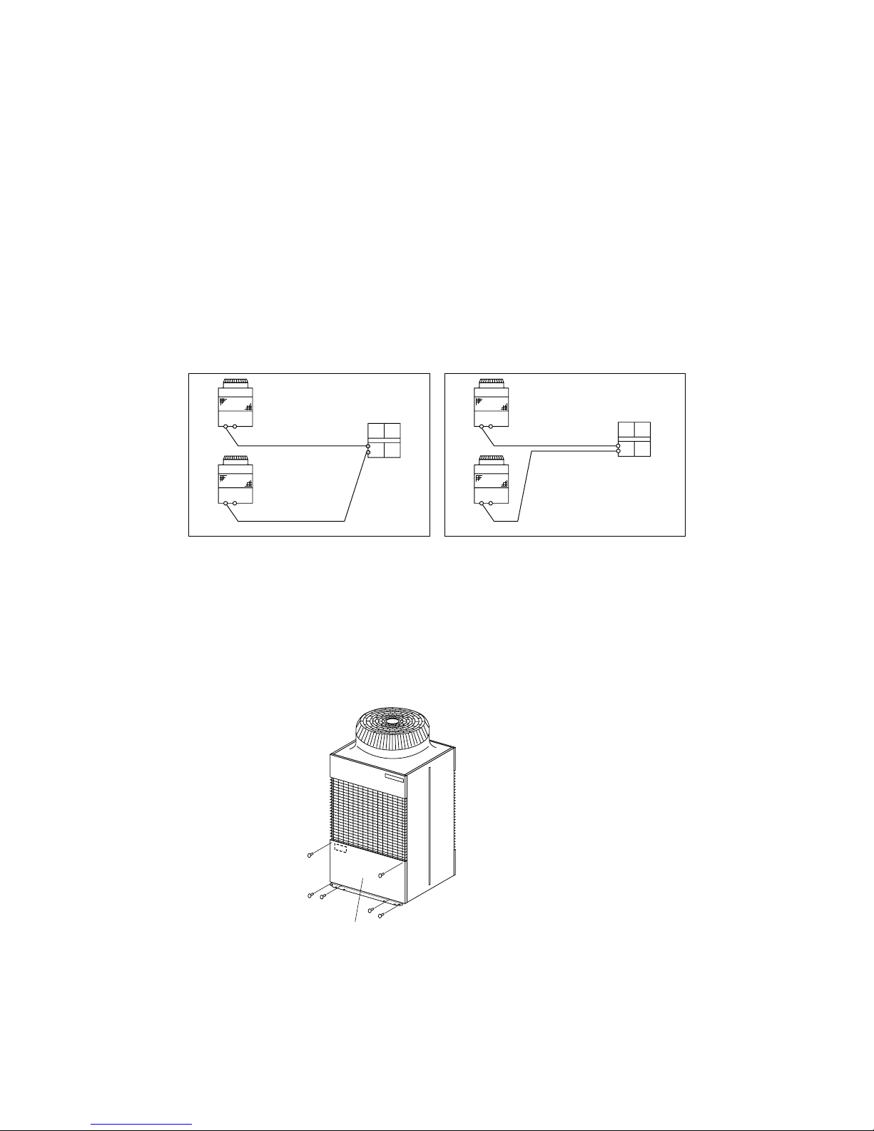
<10HP System>
<20HP System>
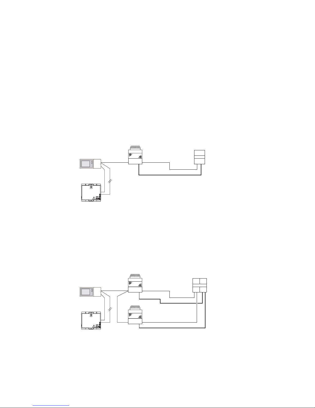
When using a PFD-P500VM-A as an indoor unit, connect 2 PUD-P250YMF-C outdoor units to each
indoor unit and operate with a built-in remote control for the indoor unit.
✻1: Bold line indicates refrigerant piping (gas/liquid). This system consists of 2 refrigerant circuits.
✻2: Indicates TB3-type transmission line that connects the indoor and outdoor units.
This system consists of 2 refrigerant circuits.
✻3: Indicates TB7-type transmission line that allows the unit to communicate with the controller.
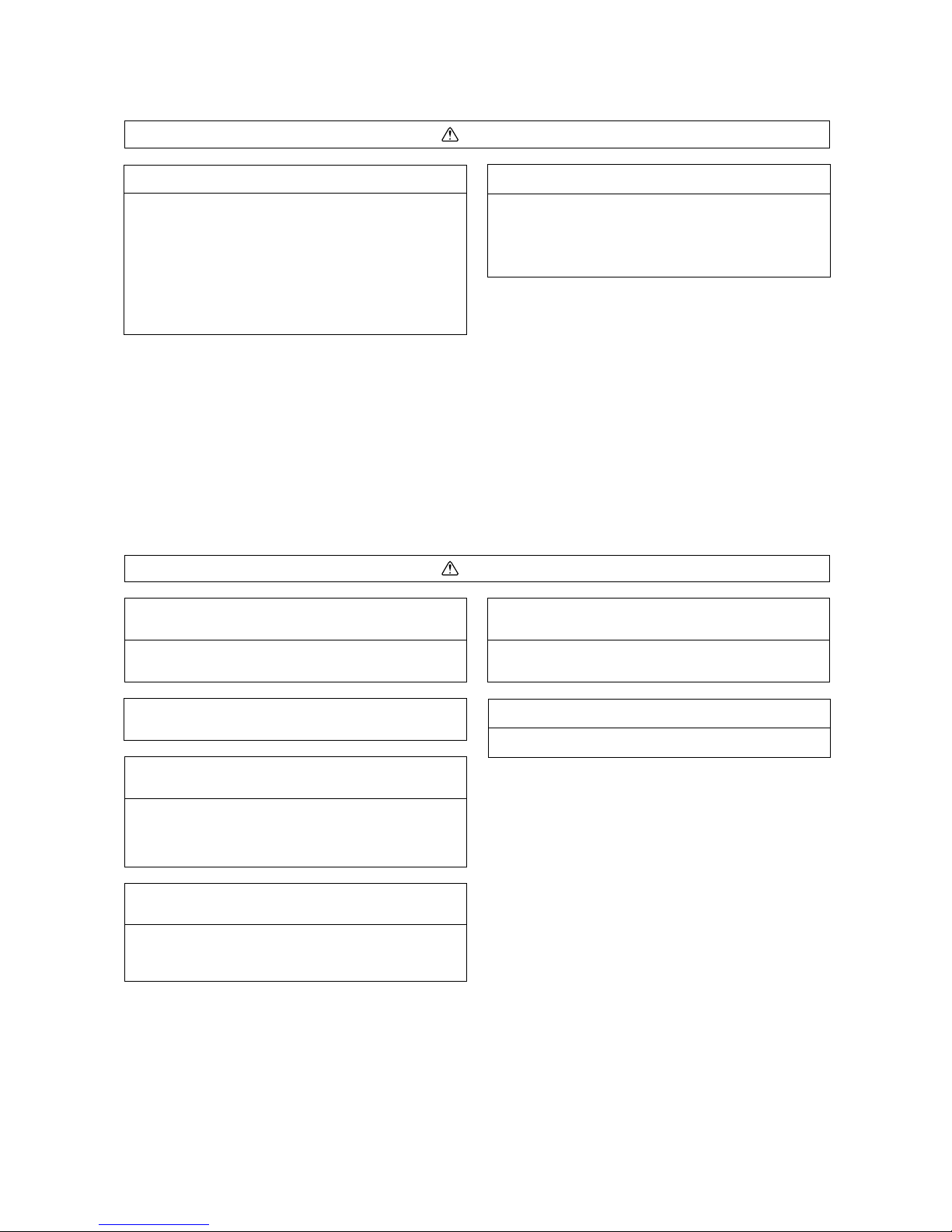
When using a PFD-P250VM-A as an indoor unit, connect an outdoor unit PUD-P250YMF-C to
each indoor unit and operate with a built-in remote control for the indoor unit.
✻1: Bold line indicates refrigerant piping (gas/liquid). This system consists of one refrigerant circuit.
✻2: Indicates TB3-type transmission line that connects the indoor and outdoor units.
This system consists of 1 refrigerant circuit.
✻3: Indicates TB7-Type transmission line that allows the unit to communicate with the controller.
Outdoor Unit
G-50A
PUD-P250YMF-C
Indoor Unit
PFD-P250VM-A
TB7
TB3 ✻2✻3
✻1
12V DC
M-NET
PAC-SC50KUA
UP
POWER RATING
MODEL
WEIGHT
SERIAL No.
2.11kg
POWER SUPPLY UNIT
MITSUBISHI ELECTRIC CORPORATION
PAC-SC50KUA
Outdoor Unit
PUD-P250YMF-C
Indoor Unit
PFD-P500VM-A
TB7
TB3 ✻2
✻1
TB3
PUD-P250YMF-C
TB7
✻3
G-50A
12V DC
M-NET
PAC-SC50KUA
UP
POWER RATING
MODEL
WEIGHT
SERIAL No.
2.11kg
POWER SUPPLY UNIT
MITSUBISHI ELECTRIC CORPORATION
PAC-SC50KUA
Page 10

- 9 -
[3] Check the symptoms of the unit requiring service.
Refer to this service manual for problems related to Freezer Cycle.
[4] Be sure to read Read Before Servicing at the beginning of this manual.
[5] Prepare necessary tools.
Do not use the same tools for units that use different types of refrigerant (especially gauze manifold and
charge hose). Doing so may cause problems. Use a vacuum pump with a reverse-flow check valve or use a
reverse flow check adapter.
[6] If the refrigerant circuit is opened (to repair gas leak etc.), the drier needs to be
replaced.
Only use the drier designed specifically for the unit. The use of other driers may result in malfunctions. Refer to
section 11 of this manual for information regarding how to change the drier.
✻ Replace the drier after completing refrigerant circuit repairs.
(If left exposed to air, the drier will absorb moisture. Replace the drier as quickly as possible after removing
the old one.)
[7] Preparing the connecting pipes: When relocating or replacing the unit, find out what
types of refrigerant is used for the unit.
Use refrigerant pipes made of C1220 phosphorus deoxidized copper categorized under H3000 (Copper and
Copper Alloy Seamless Pipes and Tubes), a standard set by JIS. Keep inner and outer surfaces of the pipes
clean and free of contaminants, such as sulfur, oxides, dust/dirt, shaving particles, oils, and moisture.
Contaminants inside the refrigerant piping will deteriorate the refrigerant oil.
[8] If there is a gas leak or if the remaining refrigerant is exposed to an open flame, a
noxious gas hydrofluoric acid may form. Provide adequate ventilation.
.
Caution
1. As soon as the old parts are removed, put in the new ones. Keep moisture from entering pipes while cooling.
2. Using refrigerant containing chlorine (such as R22) will result in the deterioration of oil in the new unit.
Page 11
- 10 -
NotesUseTools
Identification of dedicated use with
R407C: Record refrigerant name
and put a brown belt on the upper
part of the cylinder.
Use a small amount of ester oil,
ether oil, or alkybenzene.
The ones with sight glass are useful.
Can also be used with R134a.
Gauge Manifold
Refrigerant Collector
Gas Leak Detector
Charge Hose
Refrigerant Cylinder
Application Oil
Evacuating, refrigerant
charging and operation check
Gas leak detection
Refrigerant collection
Refrigerant charging
Applied to flares and flanges
Attach a reverse-flow-check adaptor
Refrigerant Cylinder Intake Refrigerant charging
Replace the packing with the one
for R407C
Modifications to Be MadeUseTools
Vacuum Pump Vacuum drying
Vacuum Pump with a Check valve
Vacuum Gauze
Refrigerant Charging Meter
Welder and Nitrogen Cylinder
Pipe Cutter
Torque Wrench
Bender
Flare Tool Flaring pipes
Checking vacuum degree
Refrigerant charging
Welding pipes
Cutting pipes
Tightening flare nuts
Bending pipes
NotesUseTools
Must not be used with R407C-type
units
NotesUse (with R22)Tools
Charging Cylinder Refrigerant Charging
22
Necessary Tools and Materials
Prepare the following tools and materials. Some of the tools should be marked for use only with units that use
R407C refrigerant.
[1] List of Tools and Materials Necessary for Units that Use R407C (and adaptability of
tools that have been used with units that use R22)
(1) To be used with R407C Only (not to be used if used with R22)
(2) Tools that may be used for R407C if necessary modifications are made
(3) Tools that are used with R22 that can also be used with R407C
(4) Tools that must not be used for R407C
Tools for R407C must be handled with special care.
Page 12

- 11 -
Do not use the piping that have been used for R22.
<Reason>
A large amount of chlorine residues from conventional refrigerator oil and refrigerant found inside the existing
piping deposit sludge in the new piping system.
<Caution>
1. When replacing the air conditioner, also replace the piping.
2. Use refrigerant pipes made of C1220 phosphorus deoxidized copper categorized under H3000 (Copper and
Copper Alloy Seamless Pipes and Tubes), a standard set by JIS. Keep inner and outer surfaces of the pipes
clean and free of contaminants, such as sulfur, oxides, dust/dirt, shaving particles, oils, and moisture.
3. Contaminants inside the refrigerant piping may deteriorate the refrigerant oil.
33
Piping Materials
NOOK
New Piping Existing Piping
Do not use the existing piping!
Page 13
- 12 -
44
Storage of Piping Materials
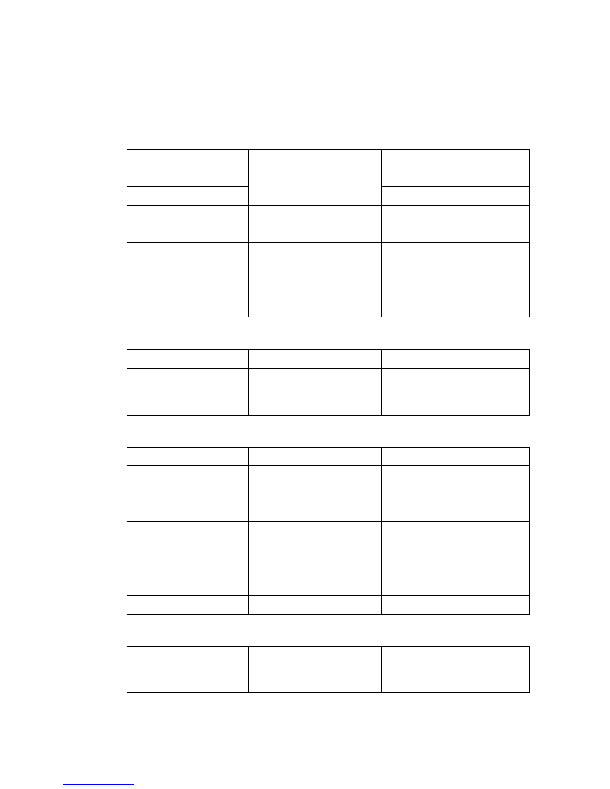
[1] Storage Location
NONO
OKOK
NONO
OKOK
Store the pipes to be used indoors (i.e. warehouse).
Storing them outdoors may cause dirt, waste, or water to infiltrate.
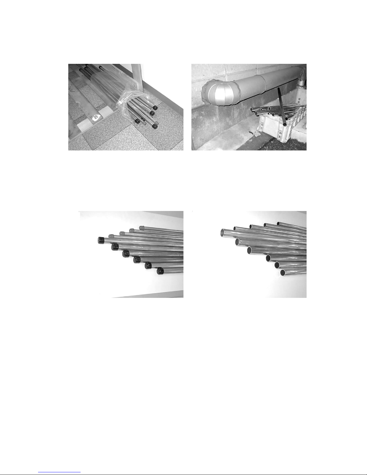
[2] Pipe sealing before storage
Both ends of the pipes should be sealed until immediately before brazing.
Wrap elbows and T’s in plastic for storage.
✻ The new refrigerator oil is ten times more hygroscopic than conventional refrigerator oils (such as Suniso).
Water infiltration in the refrigerant circuit will deteriorate the oil or cause a compressor failure. Exercise more
caution when handling piping materials for R407C air conditioners than you would when handling piping
materials for conventional units.
Page 14
- 13 -
55
Machining Pipes
Use a small amount of ester oil, ether oil, or alkylbenzene as refrigerator oil to coat flares and flange connections.
<Caution>
Use only the smallest possible amount of oil necessary.
Do not use oils other than ester oil, ether oil, or alkylbenzene.
Page 15
- 14 -
<Items to be strictly observed>
1. Do not conduct piping work outdoors on a rainy day.
2. Apply non-oxide brazing.
3. Use brazing material (BCuP-3), which requires no flux when brazing copper pipe or brazing a copper pipe and
copper coupling.
4. If the installed refrigerant pipes are not immediately connected to the unit, braze and seal both ends of the
pipes.
<Rationale>
1. The new refrigerant oil is ten times more hygroscopic than conventional oils. Special care must be taken to
keep moisture out of the system.
2. Flux generally contains chlorine. A residual flux in the refrigerant circuit may deposit sludgy materials in the
pipes.
<Caution>
Because the residue found in commercially available antioxidants may have adverse effects on the unit, use
nitrogen when performing non-oxide brazing.
66
Brazing
Although there are no changes from the conventional method, special care must be taken to keep contaminants
(i.e. oxide scale, water, dirt etc.) from entering refrigerant circuit.
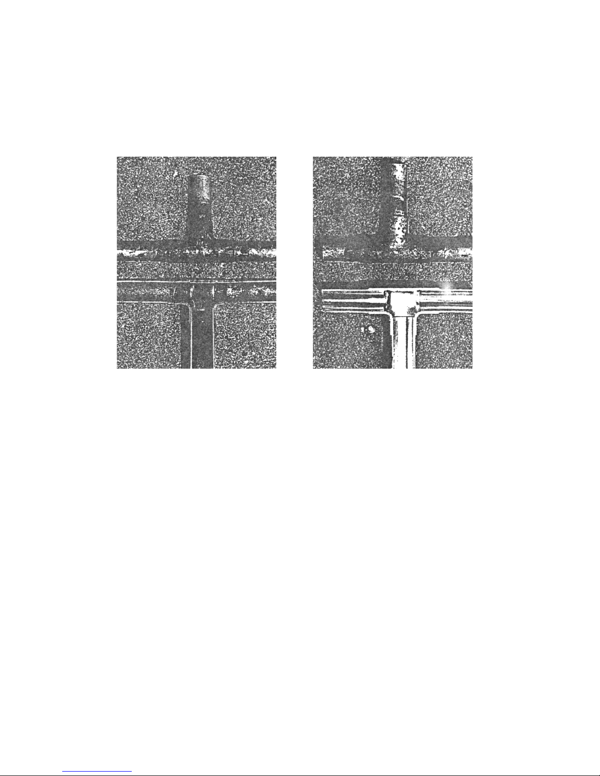
Example: Inside a brazed section
Brazed with materials other than non-oxide
brazing material
Brazed with non-oxide brazing material
Page 16
- 15 -
NO NO
77
Testing Air Tightness
There are no changes from the conventional method. Note that a refrigerant leak detector for R22 will not work
for R407C.
<Items to be strictly observed>
1. Pressurize the equipment with nitrogen up to the design pressure, and then measure the equipment’s air-tightness, taking temperature variations into account.
2. When investigating locations of leaks using a refrigerant, be sure to use R407C.
3. Make sure that R407C is in a liquid state when charging the circuit.
<Rationale>
1. Use of oxygen to pressurize the equipment may cause an explosion.
2. If gas refrigerant is used, the composition of the remaining refrigerant in the cylinder will change and become
unusable.
<Caution>
A leak detector for R407C is commercially available, and it should be acquired.
Halide Torch R22 Leak Detector
Page 17
- 16 -
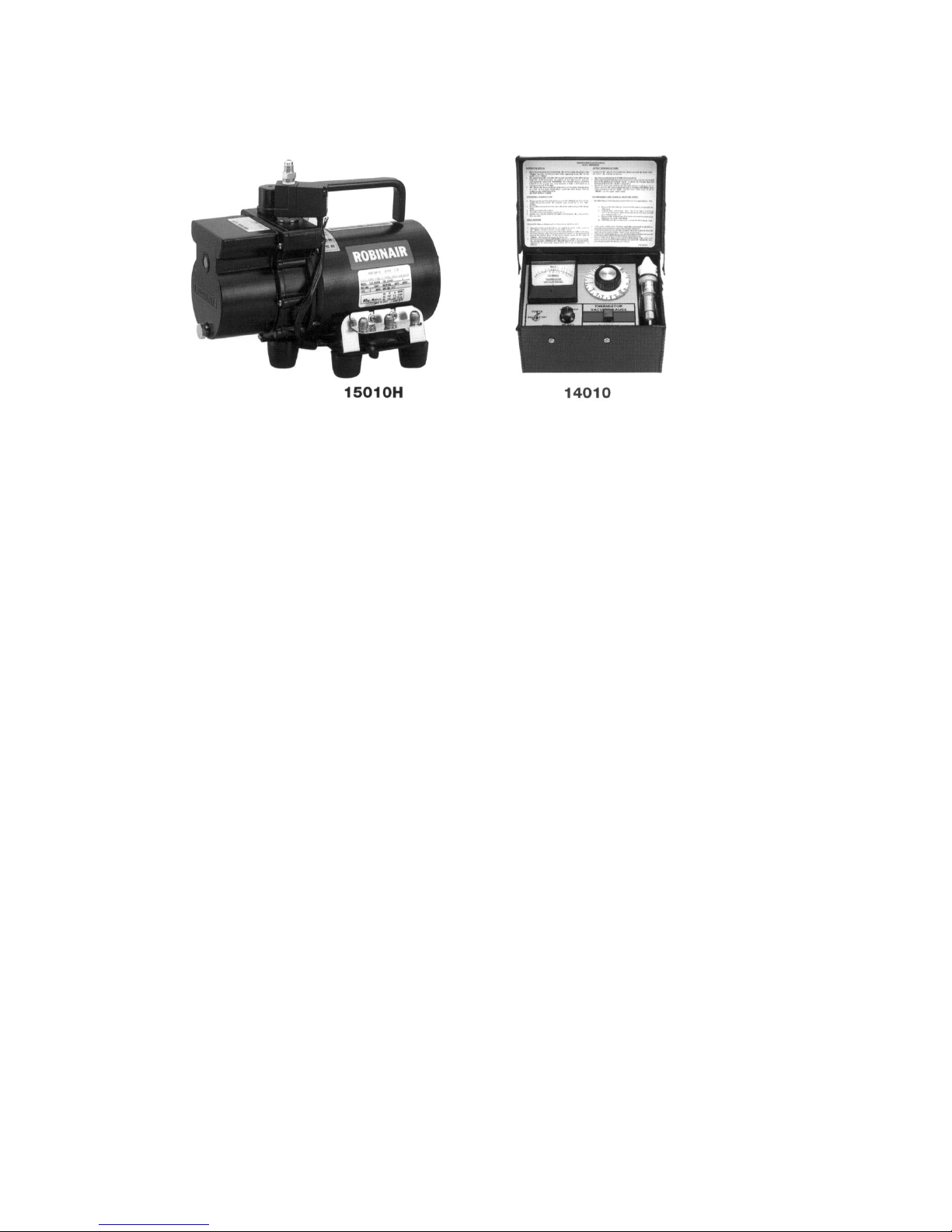
[1] Vacuum pump with a check valve (See photo 1)
A vacuum pump with a check valve is required to prevent the vacuum pump oil from flowing back into the
refrigerant circuit when the power supply is cut off unexpectedly due to power outage.
A check valve may be added to a vacuum pump that is not equipped with one.
[2] Standard degree of vacuum for the vacuum pump
Use a pump that does not exceed 65Pa after 5 minutes of operation. Be sure to use a vacuum pump that has
been properly maintained and oiled with specified oil. If the vacuum pump is not properly maintained, desired
degree of vacuum may not be achieved.
[3] Necessary Accuracy of the Vacuum Gauge
Use a vacuum gauge that can measure 650Pa and in the increments/decrements of 130Pa. Do not use gauge
manifolds that cannot measure a vacuum of 650Pa. (Recommended vacuum gauze shown in Photograph 2
above)
[4] Vacuuming time
Evacuate the equipment for one hour after reaching 650Pa. (Moisture in the air will be removed by a thorough
evacuation.)
After evacuating, leave the equipment for one hour and make sure that degree of vacuum does not rise higher
than 130Pa. Refer to section 6 “Special Vacuuming Method” if it exceeds 130Pa.
[5] How to Stop the Vacuum Pump
In order to prevent a backflow of the vacuum pump oil, open the relief valve on the vacuum pump or loosen the
charge hose to draw in air before stopping the operation. The same operating procedure should be followed
when using a vacuum pump with a check valve.
[6] Special Vacuuming Method
Water infiltration or leakage is suspected when the degree of vacuum does not go below 650Pa after running
the vacuum pump for more than 3 hours. Check for leakage and water infiltration.
If water infiltration is the suspected cause, break vacuum with nitrogen. Then, pressurize nitrogen gas to
0.05MPa and try evacuating again. Repeat the procedure until the degree of vacuum goes below 650Pa or
until the pressure stops rising.
Be sure to use nitrogen to break vacuum. (The use of oxygen may cause an explosion)
Photograph 1 Photograph 2
Photograph 1 Recommended Vacuum Gauge : ROBINAIR 14010 Thermistor Vacuum Gauge
88
Vacuum Drying (Evacuating)
Page 18
- 17 -
99
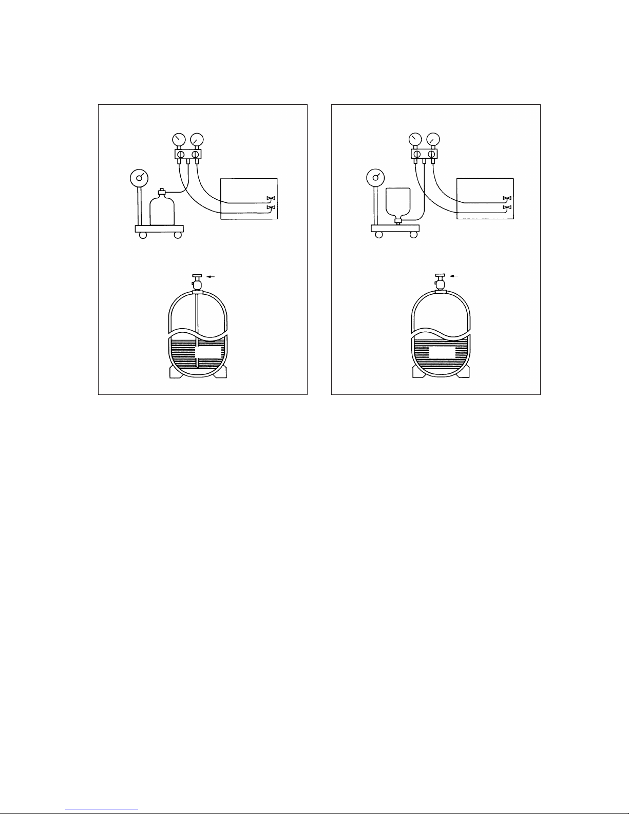
Charging the Circuit with Refrigerant
R407C must be in a liquid state when charging the circuit because it is a non-azeotropic refrigerant.
<Rationale>
1. R407C is a mixture of three refrigerants, each with a different evaporation temperature. If the equipment is
charged with R407C gas, only the refrigerant that evaporates most easily is charged, while the rest of the
refrigerants remain in the cylinder.
<Caution>
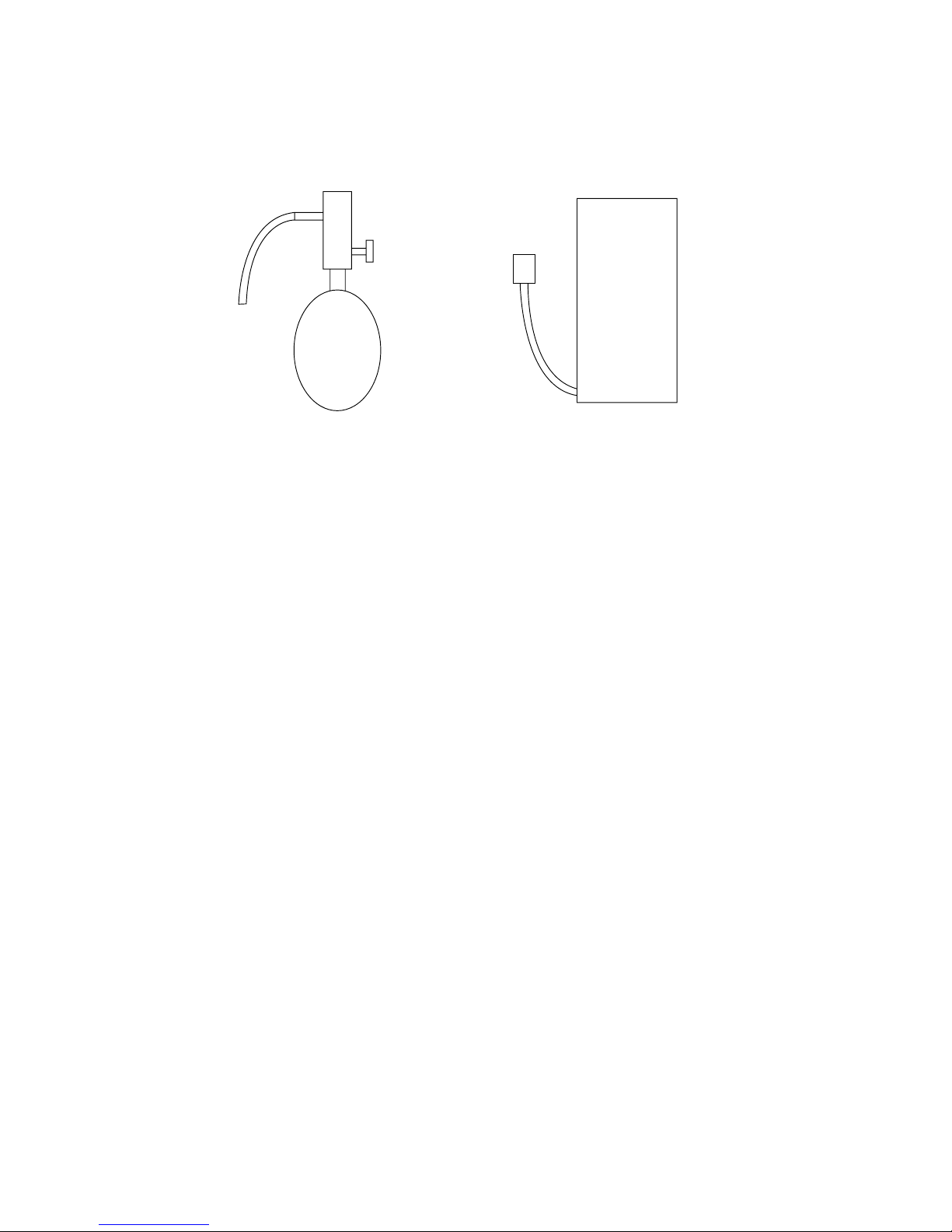
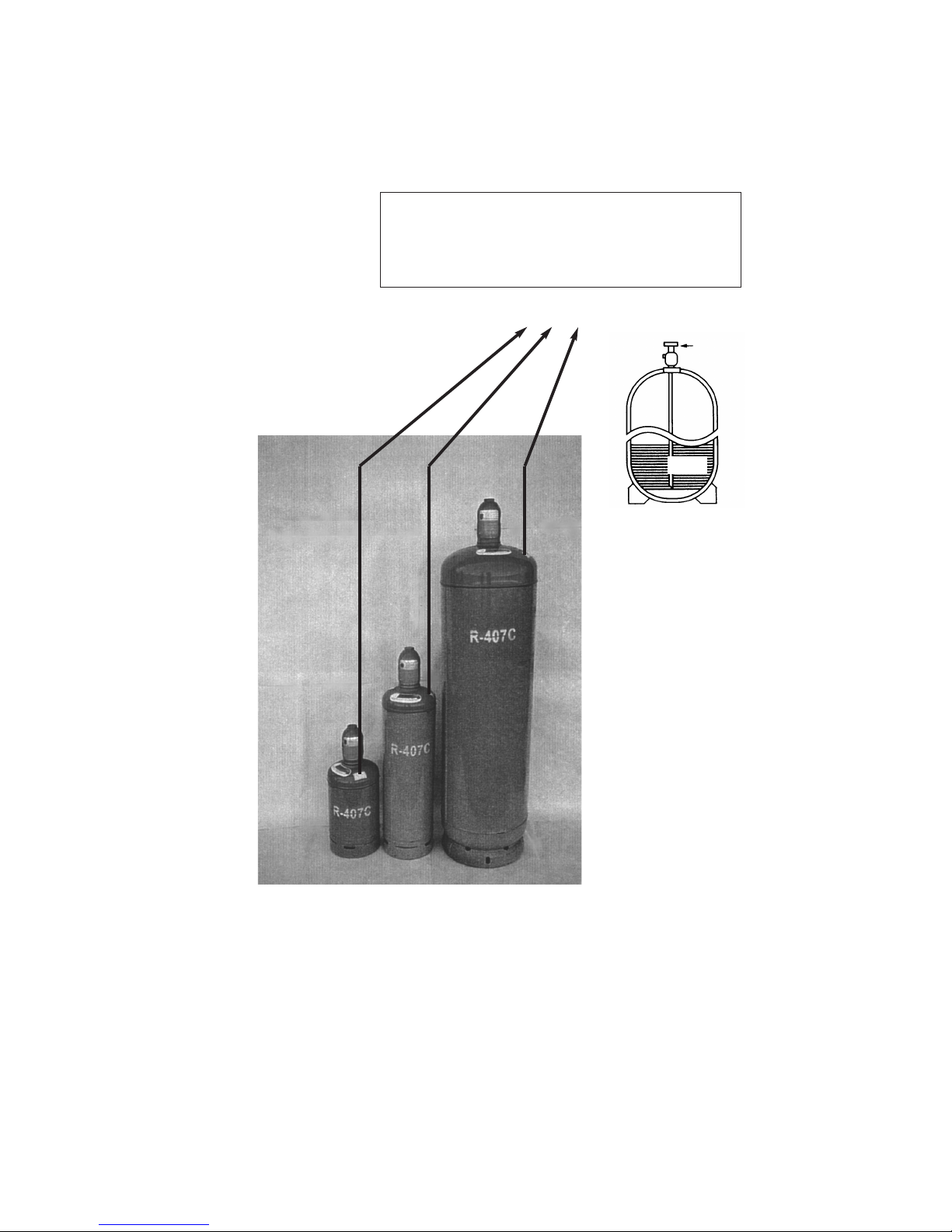
Do not use cylinders with a siphon upside-down.
When using a cylinder with a siphon, R407C is charged in a liquid state without the cylinder being turned upsidedown. Check the label on the cylinder for information about the type of cylinder before the operation. (Cylinders
with siphons manufactured by Asahi Glass are shown on Page 18)
cylinder with a siphon
Cylinder color R407C-Brown
Cylinder
Cylinder
cylinder without a siphon
Use liquid refrigerant
Valve Valve
Liquid Liquid
Page 19
- 18 -
Enlargement
Valve
Liquid
R407C Cylinder with siphon: Manufactured by Asahi Glass
.
Caution
The cylinders shown below are equipped with siphons.
When using this type of cylinders, place the cylinder
with the siphon facing up.
Page 20
- 19 -
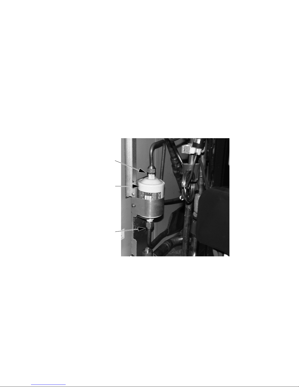
Drier
Direction of the flow Top to bottom
ø 9.52
Flare connection
ø 12.7
Flare connection
,
AA
Replacing the Drier
==
What to Do When Refrigerant Leaks
As with conventional air-conditioning units, refrigerant can be added to what remains in the circuit, for the unit is
equipped with a CS circuit (Circulating-Refrigerant-Composition-Detector) Refer to section X of this handbook for
more information.
✻ When using water-cooled heat-source unit, please note that CS circuit is only found on the inverter side, but not
on the constant-rate side.
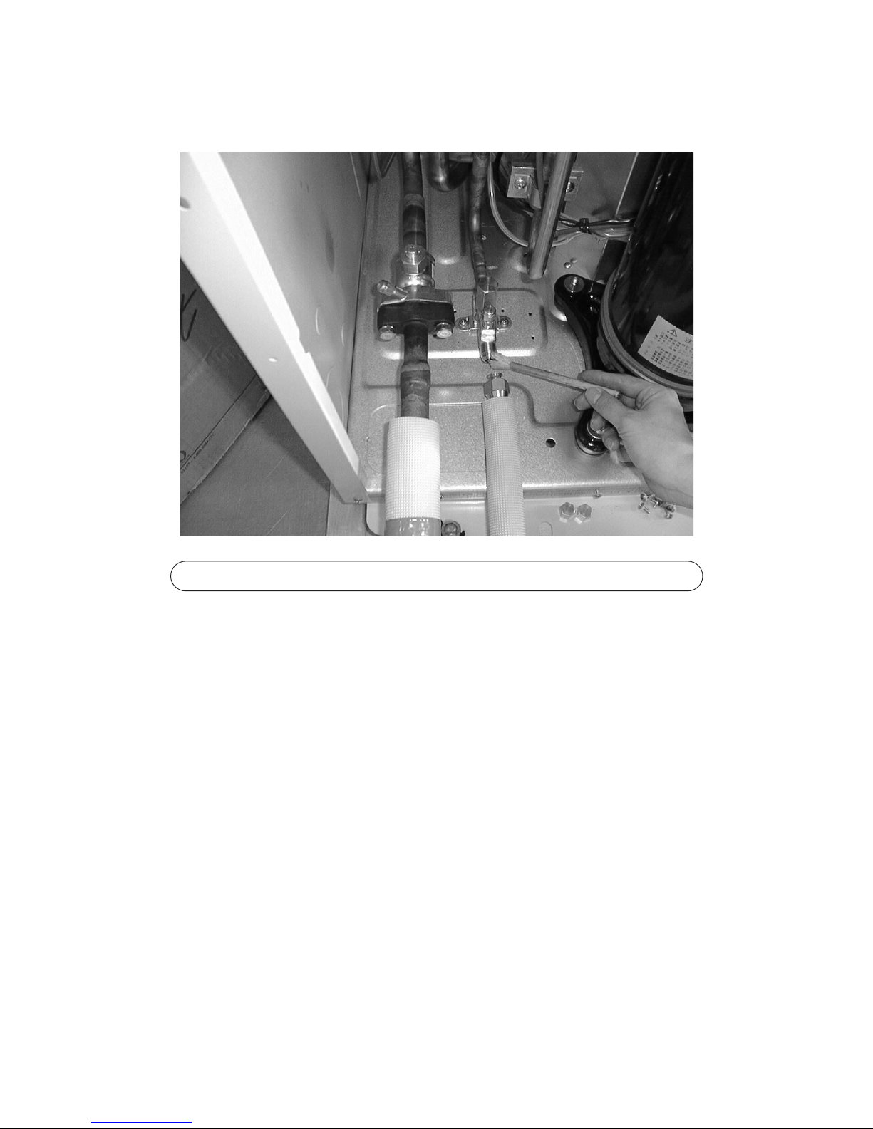
1. Replace the drier when the refrigerant circuit is opened. Only use the drier specified for this unit. The use of any
other drier will cause malfunctions.
2. Install the drier as shown in the photograph below. Do not attach driers to a pipe;
doing so may cause problems.
3. Do not leave the refrigerant circuit open for longer than one hour after removing the old drier. The replacement of
the drier should be performed last when performing multiple jobs.
Page 21

- 20 -
11
. Restrictions
11
System Restrictions and System Configuration
Each unit of the Split-Type Air Conditioners for Computer Rooms comes as a part of a system. For each unit to be
integrated into the system, the system requires a series of switch setting. Be sure to read the following to properly
configure the system.
[1] Switch Setting
(1) Types of Switches
✻ Inside indoor units, there is a control board for each refrigerant system.
Be sure to set the address for each of the control board.
2 Two or more identical addresses cannot coexist in the same system. If two or more of the same address
are used, the unit will not run properly.
(3) How to Set the Switches
1 Address Switch
(2) Notes on Switch Setting
1 Cut off the power supply before changing switch settings.
If the settings are changed while power is supplied to the unit, the change will not take effect, and it will
cause the unit to malfunction.
Type Outdoor Unit Indoor Unit
Address Switch rotary
™™
✻1
Power-Source Switch Connector 4-Pin connector CN40
™
Switches to Be Operated Cut off the power supply to
Outdoor Unit Outdoor unit
Indoor Unit Outdoor and Indoor Units
Unit Type
Setting
Range
Digits Setting Method
Factory
Setting
Indoor Unit 1-50 2
(the hundred's
digit is always
set to 0)
Outdoor Unit 51-100 2
00
00
(the hundred's
digit is always
set to 0)
· Use numbers between 1-50.
All the indoor units controlled by the same centralized
controller should be assigned sequential numbers
starting with 01.
· Only use odd numbers to set the top controller of the
indoor unit.
· To set the bottom controller of indoor units, add one to
the address of the top controller in the same unit. If
P250 and P500 systems coexist, Refer to P34.
· The address for the outdoor unit should equal the
address the of the indoor controller address in the
same refrigerant system plus 50.
Page 22
- 21 -
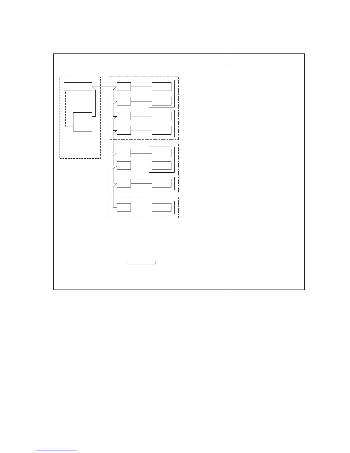
(4) Example
Below is a typical setting of a system
Outdoor Units
Indoor UnitsController board
DC12V
Powe r
supply
line
Powe r
supply
unit
51
52
53
54
55
56
01
G-50A
02
03
04
05
06
0 1
57 07
59 09
Group 1
Group 2
Group 3
✻ There are two
controller boards
inside indoor units.
(for P500 type)
✻ There are one
controller board
inside indoor units.
(for P250 type)
SW12 SW11
Unit Address
10´s
Digits
Single
digits
Switch Setting
1 Set indoor unit address
using sequential numbers.
(P500 only)
2 To set the address for the
outdoor unit, add 50 to the
address for the indoor unit
to which the outdoor unit
is connected.
Diagram Comments
Page 23
- 22 -
b) The control box cover consists of two parts (top and bottom parts). Each can be removed separately
by unscrewing two screws and pulling the cover down. Connectors and dipswitches on the main board
can be operated by removing only the top part. Only remove the bottom part when servicing power
supply lines and transmission lines.
a) Remove the service panel by unscrewing the 6 screws as shown in the picture on the right.
(2) Control Box and Location of Terminals
1 Outdoor Unit
Front Panel
22
Restrictions on Transmission Lines
[1] Electrical Wiring
(1) Attention
1 Follow ordinance of your governmental organization for technical standard related to electrical equipment,
wiring regulations, and guidance of each electric power company.
2 Wiring for control (hereinafter referred to as transmission line) shall be (5cm or more) apart from power
source wiring so that it is not influenced by electric noise from power source wiring.(Do not insert transmission line and power source wire in the same conduit.)
4 Give some allowance to wiring for electrical part box of indoor and outdoor units, because the box is
sometimes removed at the time of service work.
5 Never connect 380~415V(220~240V )power source to terminal block of transmission line.If
connected,electrical parts will be burnt out
6 Use 2-core shield cable for transmission line. If transmission lines of different systems are wired with the
same multiplecore cable, the resultant poor transmitting and receiving will cause erroneous operations.
NOOK
TB3
TB7
TB3
TB7
TB3
TB7
TB3
TB7
Multiple-core Cable
2-core Cable
2-core Cable
Indoor Unit
Indoor Unit
Outdoor Unit
Outdoor Unit
Page 24
- 23 -
2 How to Use Conduit Mounting Plates
Conduit mounting plates (
ø 27, ø 33, ø 40) are packaged with the unit. Use an appropriate plate depend-
ing on the diameter of the wire used. Mount the plate as shown below.
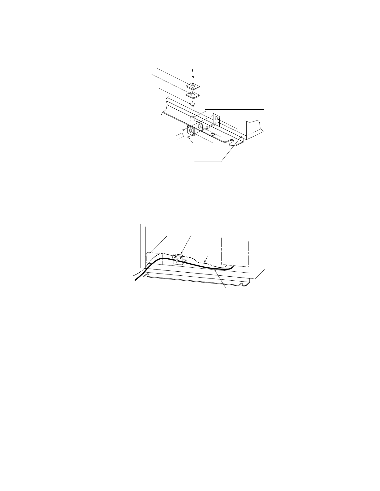
3 How to Mount the Attachment Plate
When using either the left or front knock-out holes for both power-supply line and transmission line, screw
on an attachment plate with two screws (see below). Fix the power-supply line with the bottom clamp, and
fix the transmission line with the top clamp.
Front side
Controller
box
Transmission line
Power-Source line
Attachment plate
Use this hole when threading
the wire through the bottom hole
ø33 mounting plate
ø
40 mounting plate
ø27 mounting plate
ø27 mounting plate
ø33 mounting plate
ø
33 mounting plate
ø40
knockout hole
Tapping screw
Front Side of
the Panel
Use this hole when threading
the wire through the front hole.
Page 25
- 24 -
Transmission line is a type of control line. When the source of noise is located adjacent to the unit, the use of
shield cable as well as moving the unit as far away from the noise source are recommended.
1 Transmission line (M-NET transmission line)
For multiple-refrigerant system
Length of transmission line
Facility type
(noise level measurement)
No. of cable 2-core cable
Diameter Over 1.25mm
2
Wiring specifications
All types of facilities
n/a
Shield cable
CVVS · CPEVS
System component
Maximum length: 200m
Maximum length of centralized control transmission line and Indoor/Outdoor
transmission line via indoor/outdoor units: 500m maximum
Total length of indoor/outdoor transmission line
Cable type
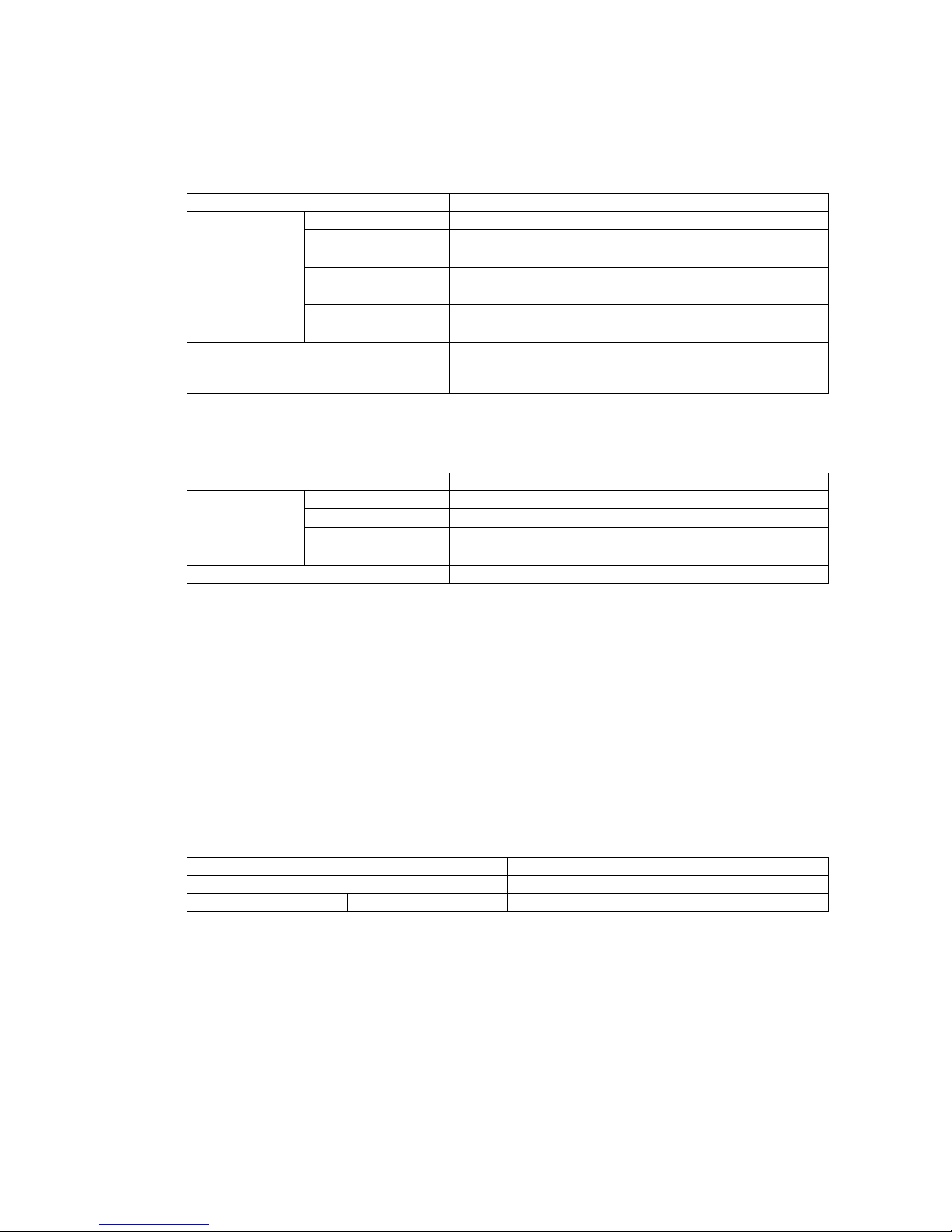
(4) Types of switch settings and setting methods
Whether a particular system requires switch settings depends on its components. Refer to the section
“(5) Examples” before conducting electrical work.
Keep the power turned off while setting the switches. If settings are changed while being powered, the
changed settings will not register, and the unit may malfunction.
Symbol
Outdoor unit OC
Indoor unit
✻ 10HP has only the main controller
Main/sub controllers ✻ IC
Turn off the power to
Outdoor unit
Indoor and outdoor units
Unit
2 Remote control wiring
MA remote controller ✻ 1
No. of cable 2-core cable
Diameter
0.3
~1.25mm
2
(0.75~1.25mm2)
✻ 2
✻ 3
Wiring specifications
CVV
Maximum length: 200 m
Total Length
✻ 1: “MA remote controller” includes MA remote controller, Simple MA controller, and wireless remote controller.
✻ 2: Cables with a diameter of 0.75mm
2
or smaller recommended for easier handling.
✻ 3: When connecting to simple remote controller terminal, use a cable with a diameter within the range shown in
the parenthesis.
Cable type
(3) Control Wiring
Page 26
- 25 -
1 Address setting
This system requires address setting. The range of address varies depending on the type of unit.
Refer to “(5) Examples” for details.
3 Choosing the temperature detection spot by indoor unit (Factory Setting: SWC “Standard”)
When using the suction temperature sensor, set SWC to “Option.”
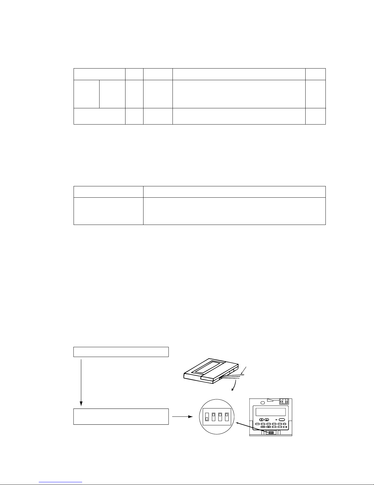
4 Setting the MA “Sub” controller
When using two remote controllers or running two indoor units as a group, one of the controllers must be
set to “Sub” controller.
✻ No more than two remote controllers can be connected to a group.
(Factory setting: “Main”)
Set the controller according to the following procedure. Refer also to the instructions manual supplied with
the MA remote controller.
Factory
setting
Indoor unit
Main/sub
controllers
✻ 1
Symbol Setting method
IC
OC
00
00
Address
setting range
01
~50
✻ 2
51
~100
✻ 2 ✻ 3
Unit
Outdoor Unit
✻ 1: 10HP only has the main controller.
✻ 2: Avoid using the same address as the ones used by the indoor/outdoor units in another refrigerant system; choose a different
one in the range specified above.
✻ 3: When setting the address to 100, set the switch to 50.
Assign a number to all indoor units, starting with 1 and using
sequential numbers. Use odd numbers for the top controller and
even numbers for the bottom controller of the indoor units. Use
odd numbers starting with 01 for 10HP system.
Add 50 to the address assigned to the indoor unit to which the
outdoor or heat-source unit is connected.
2 Setting the outdoor unit power-source switch connector (Factory setting: CN41 Connected)
Power supply switch unit
<When power-supply unit is not connected to the centralized control transmission line>
Replace the power source switch connector CN41 with CN40 on only one of the outdoor units
<When connecting the power-supply unit>
Use CN41 as it is.
System component
Multiple-refrigerant system
Remote controller bodyDip switches
1ON234
Screwdriver
Remove the cover on the remote controller
Set Dip Switch No.1 on the remote
controller to “OFF” (Main to Sub)
Insert a flat-head screwdriver in the
groove shown in the picture, and
move the screwdriver in the direction
shown in the arrow.
Page 27
- 26 -
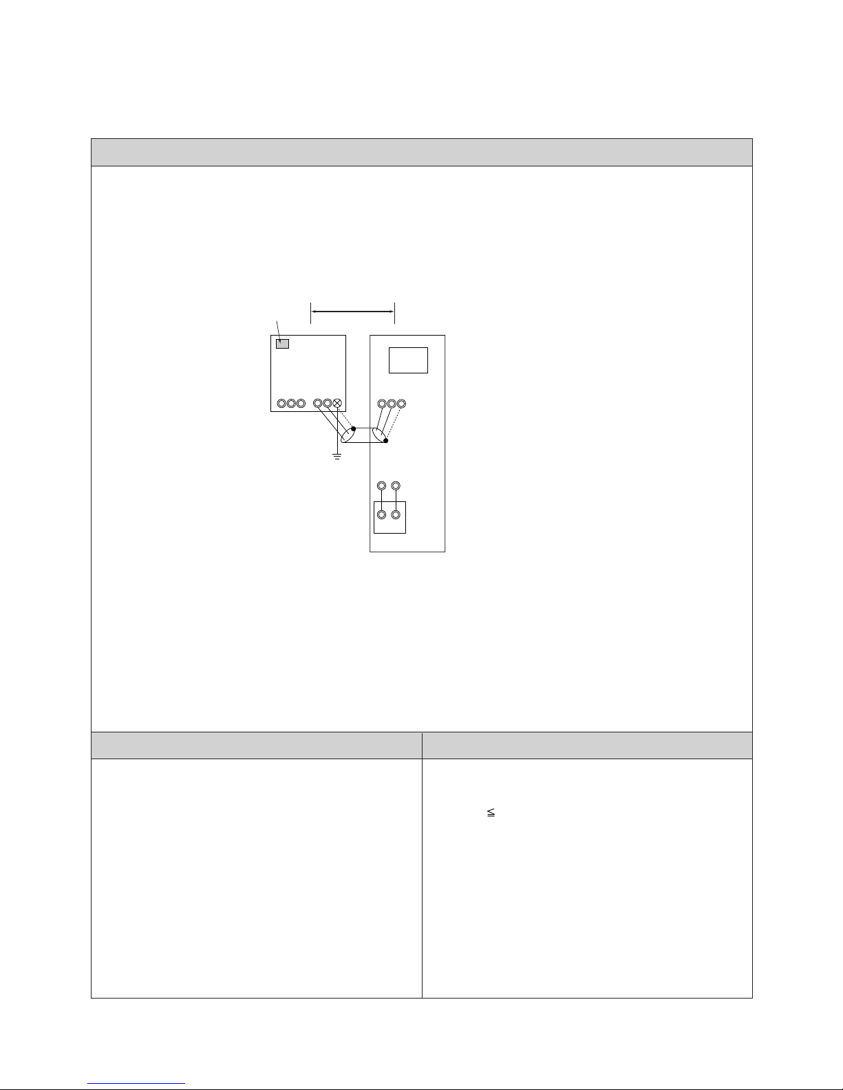
(5) Examples
1
System Using MA Remote Controller
(1) System with one indoor unit (10HP system)
Remarks Maximum Allowable Length
Control Wiring Diagram
<a. Indoor/Outdoor transmission line>
Maximum Length (above 1.25mm
2
)
L1 200m
1. Use power supply connector (CN41) on the outdoor
unit as is.
2. It is not necessary to ground the S terminal of
centralized control transmission terminal board (TB7)
on the outdoor unit.
3. The outdoor unit cannot be connected to indoor units
other than the PFD-type ones.
OC
TB3
TB7
EAB
ABS
51
IC
MA
TB5-1
ABS
01
TB15
12
A1 B2
L1
Use CN41 as is.
✻There is one indoor controller
board inside indoor unit.
Page 28
- 27 -
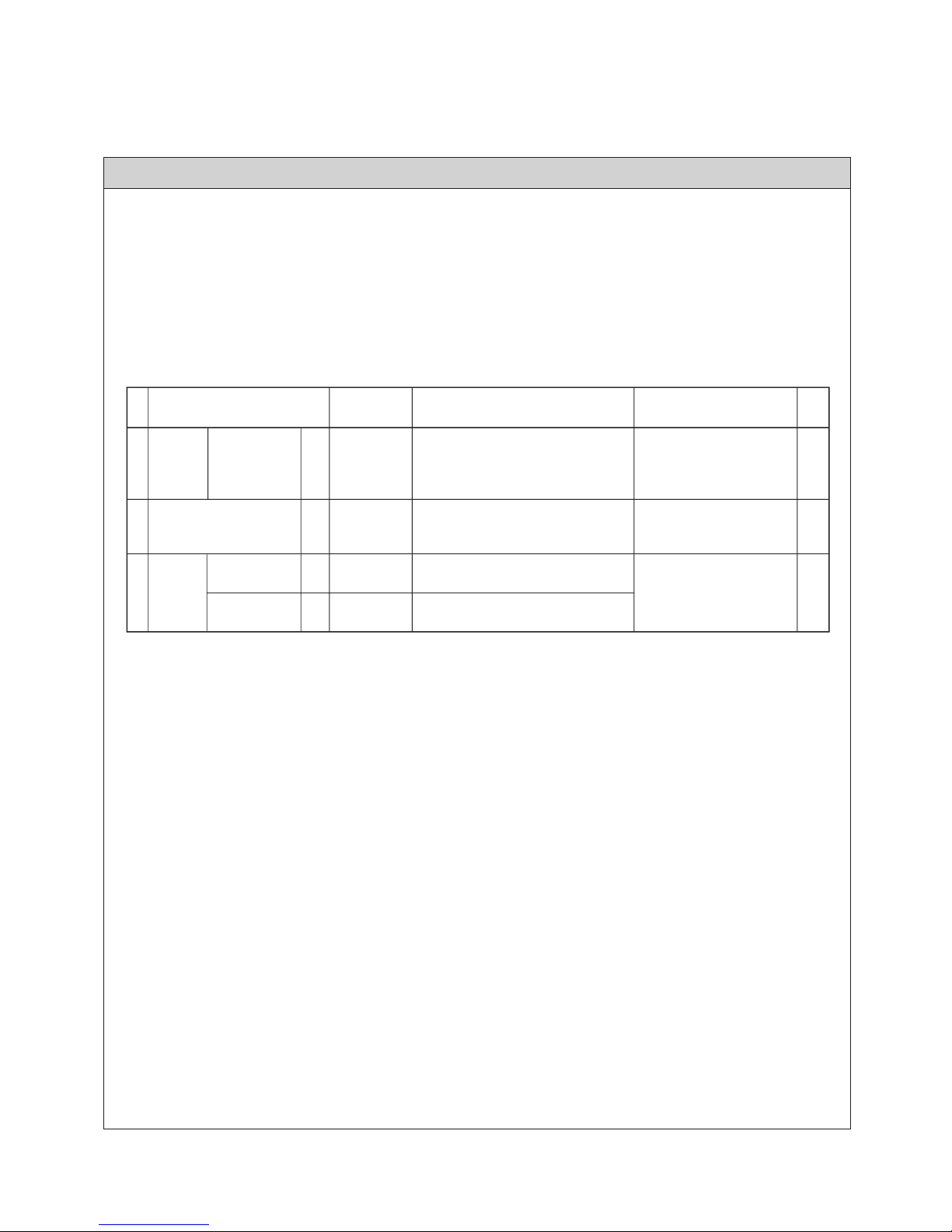
Wiring and Address Setting
<a. Indoor/Outdoor Transmission Lines >
Connect A, B terminals of indoor/outdoor transmission line terminal board (TB3) on the outdoor unit and A, B
terminals of the Indoor/outdoor transmission terminal board (TB5). (Non-polar 2 wire)
✻ Only use shield line.
[Grounding the shield line]
Connect the earth terminal of the OC and S terminal of the IC terminal board (TB5).
<b. Switch Setting >
Set the address as follows.
MA
remote
controller
Sub Controller
Main ControllerMAMA
3
n/a
Main
Unit or Controller
Address
Setting Range
Steps
Factory
Setting
Setting Procedures
Indoor
Unit
Outdoor Unit
Main Unit IC
OC
1
2
Remarks
51 ~ 100
Sub controller
01 ~ 50 00
00
Set the address for the controller at the
top of the indoor unit. Start with "01"
then use sequential odd numbers
(i.e.01, 03, 05).
Add 50 to the address assigned to the
indoor unit within the same refrigerant
system.
Use dipswitch to set the controller as
sub controller.
-
Page 29
1
System Using MA Remote Controller
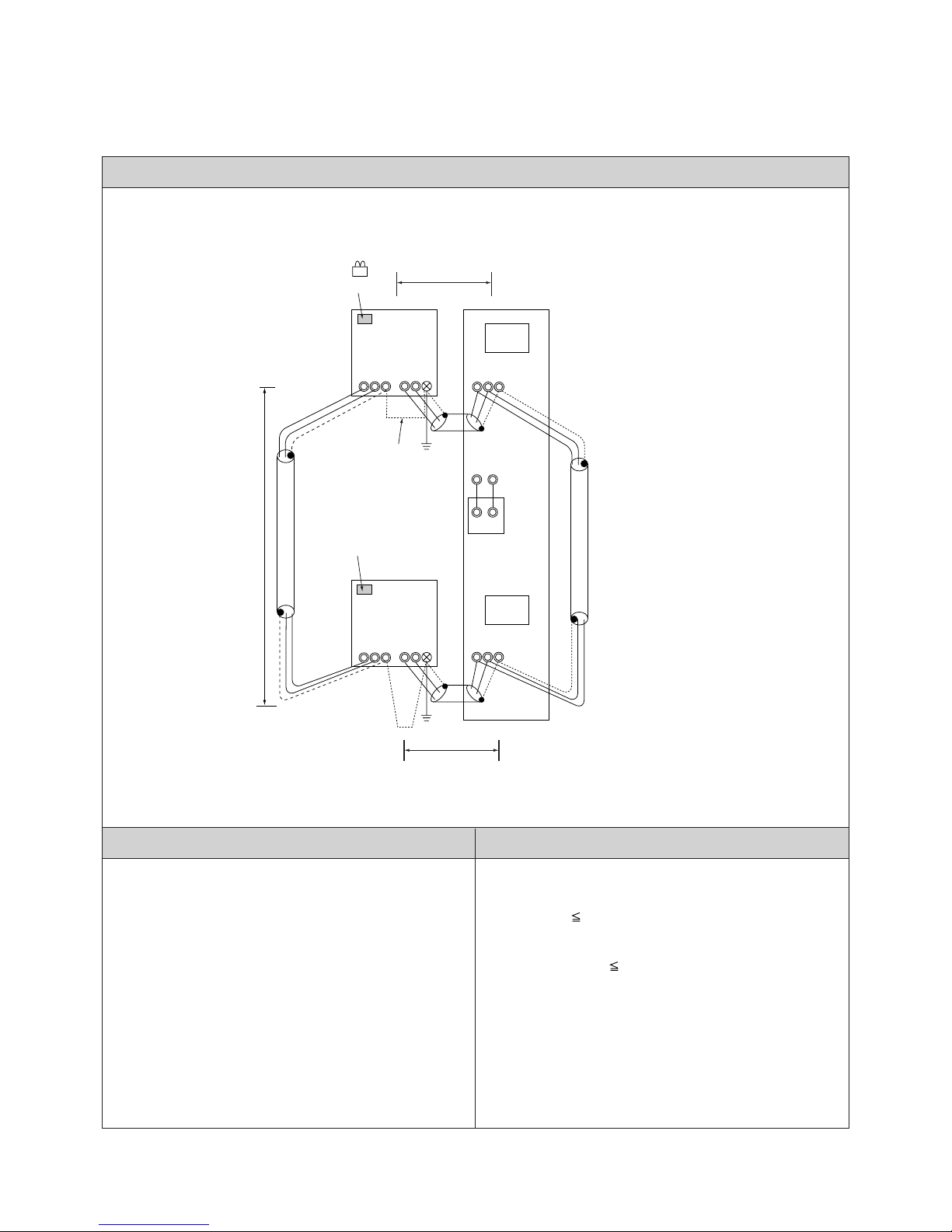
(2) Unit with One Indoor Unit (20HP Systems)
Remarks Maximum Allowable Length
Control Wiring Diagram
1. Use sequential numbers to set indoor unit address.
2. Do not connect TB5s' of the indoor units that are
connected to different outdoor units with each other.
3. Replace CN41 with CN40 on only one outdoor unit.
4. Ground only one of the outdoor units' S terminal of
TB7 (centralized control transmission terminal).
5. The outdoor unit cannot be connected to indoor units
other than the PFD-type ones.
<a. Indoor/Outdoor transmission line>
Maximum Length (above 1.25mm
2
)
L1, L2 200m
<b. Transmission line for centralized control>
Maximum length via outdoor unit (over 1.25mm
2
)
L1 + L3 + L2 500m
NO
NO
OC
TB3
TB7
EAB
ABS
51
IC
MA
TB5-1
ABS
01
TB5-2
ABS
TB15
12
A1 B2
02
OC
TB3
TB7
EAB
ABS
52
L31
L1
L2
Use CN41 as is.
✻There are 2 indoor controller
boards inside indoor unit.
Replace CN41 with CN40.
Conect
- 28 -
Page 30
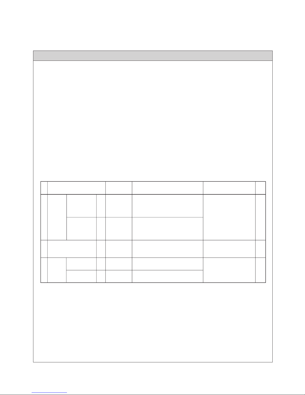
Wiring and Address Setting
<a. Indoor/Outdoor Transmission Lines >
Connect A, B terminals of indoor/outdoor transmission line terminal board (TB3) on the outdoor unit and A, B
terminals of the Indoor/outdoor transmission terminal board (TB5). (Non-polar 2 wire)
✻Only use shield line.
[Grounding the shield line]
Connect the earth terminal of the OC and S terminal of the IC terminal board (TB5).
<b. Transmission Line for Centralized Control >
Connect A terminals of centralized control transmission line terminal board on each of the outdoor units with each
other.
Do the same with B terminals. Replace CN41 (power supply switch connector) with CN40 on only one OC.
✻Only use shield line.
[Grounding the shield line]
Connect S terminals of the TB7 of each of the outdoor units with each other.
Connect the S terminal of TB7 on the outdoor unit whose CN41 was replaced with CN40 to the earth terminal of
the electric box.
<c. Switch Setting >
Set the address as follows.
MA
remote
controller
Sub Controller
Main ControllerMAMA
3
n/a
Main
Unit or Controller
Address
Setting Range
Steps
Factory
Setting
Setting Procedures
Indoor
Unit
Outdoor Unit
Main Unit IC
OC
1
2
Remarks
51 ~ 100
Sub controller
01 ~ 49
00
00
Set the address for the controller at the
top of the indoor unit. Start with "01"
then use sequential odd numbers
(i.e.01, 03, 05).
Add 50 to the address assigned to the
indoor unit within the same refrigerant
system.
Use dipswitch to set the controller as
sub controller.
-
Sub Unit IC 02 ~ 50
Add 1 to the address assigned to the
main unit in the same room.
- 29 -
Page 31

1
System Using MA Remote Controller
(3) When connecting 2 MA remote controller to one indoor unit (20HP Systems)
Remarks Maximum Allowable Length
Control Wiring Diagram
1. Use sequential numbers to set indoor unit address.
2. Do not connect TB5s' of the indoor units that are
connected to different outdoor units with each other.
3. Replace CN41 with CN40 on only one outdoor unit.
4. Ground only one of the outdoor units' S terminal of
TB7 (centralized control transmission terminal).
5. No more than two main and sub controllers can be
connected to the indoor unit in the same group.
Disconnect the MA remote control wire from TB15 if
using more than 2 remote controllers.
6. The outdoor unit cannot be connected to indoor units
other than the PFD-type ones.
<a. Indoor/outdoor transmission line >
Same as (2).
<b. Transmission line for centralized control >
Same as (2).
<c. MA remote controller wiring >
Maximum allowable length (0.3
~ 1.25mm2)
m1 + m2 200m
NO
NO
NO
OC
TB3
TB7
EAB
ABS
51
IC
MA(Main)
TB5-1
ABS
01
TB5-2
ABS
TB15
12
A1 B2
MA(Sub)
A1 B2
MA
A1 B2
02
OC
TB3
TB7
EAB
ABS
52
L31
L1
L2
Use CN41 as is
✻There are 2 indoor controller
boards inside indoor unit.
Replace CN41 with CN40
Connect
m1m2
- 30 -
Page 32

Wiring and Address Setting
<a. Indoor/Outdoor Transmission Line >
Same as (2).
<b. Transmission Line for Centralized Control >
Same as (2).
<c. MA Remote Controller Wiring >
[When using 2 remote controllers]
When using two remote controllers, connect terminals 1 and 2 of TB15 on the indoor unit to terminal board of MA
controller(option).
✻ Set the connected MA remote controller (option) as sub controller (Refer to manual that came with MA remote
controller.)
<d. Switch Setting >
Set the address as follows.
MA
remote
controller
Sub Controller
Main ControllerMAMA
3
n/a
Main
Unit or Controller
Address
Setting Range
Steps
Factory
Setting
Setting Procedures
Indoor
Unit
Outdoor Unit
Main Unit IC
OC
1
2
Remarks
51 ~ 100
Sub controller
01 ~ 49
00
00
Set the address for the controller at the
top of the indoor unit. Start with "01"
then use sequential odd numbers
(i.e.01, 03, 05).
Add 50 to the address assigned to the
indoor unit within the same refrigerant
system.
Use dipswitch to set the controller as
sub controller.
-
Sub Unit IC 02 ~ 50
Add 1 to the address assigned to the
main unit in the same room.
- 31 -
Page 33

1
System Using MA Remote Controller
(4) When grouping 2 indoor units (20HP systems) with MA remote controller
Remarks Maximum Allowable Length
Control Wiring Diagram
1. Use sequential numbers to set indoor unit address.
2. Do not connect TB5s' of the indoor units that are
connected to different outdoor units with each other.
3. Replace CN41 with CN40 on only one outdoor unit.
4. Ground only one of the outdoor units' S terminal of
TB7 (centralized control transmission terminal).
5. No more than two main and sub controllers can be
connected to the indoor unit in the same group.
Disconnect the MA remote control wire from TB15 if
using more than 2 remote controllers.
6. The outdoor unit cannot be connected to indoor units
other than the PFD-type ones.
<a. Indoor/outdoor transmission line >
Same as (2).
<b. Transmission line for centralized control >
Same as (2).
<c. MA remote controller wiring >
Maximum allowable length (0.3
~ 1.25mm2)
m1 + m2 + m3 200m
NO NO
OC
TB3
TB7
EAB
ABS
51
IC
MA
(Main)
TB5-1
ABS
01
TB5-2
ABS
TB15
12
A1 B2
02
OC
TB3
TB7
EAB
ABS
52
OC
TB3
TB7
EAB
ABS
53
IC
MA(Sub)
TB5-1
ABS
03
TB5-2
ABS
TB15
12
A1 B2
04
OC
TB3
TB7
EAB
ABS
54
L31
L31
L1
m3
m1
Use CN41 as is.
✻There are two indoor controller
board inside each indoor unit.
Replace CN41 with CN40.
L1
L2
m2
Use CN41 as is.
L2
Replace CN41 with CN40.
Connect Connect
- 32 -
Page 34

Wiring and Address Setting
<a. Indoor/Outdoor transmission line >
Same as (2).
<b. Transmission Line for Centralized Control >
Same as (2).
<c. MA remote controller line >
✻ When grouping units that use different refrigerants, set MA remote controller of one of the indoor units as sub
controller.
[When grouping indoor units]
When grouping indoor units, connect 1 and 2 terminals of both IC terminal boards (TB15) with each other (non-
polar 2 line).
✻ Set MA remote controller of one of the indoor units as sub controller.
<d. Switch Setting >
Set the address as follows.
MA
remote
controller
Sub Controller
Main ControllerMAMA
3
n/a
Main
Unit or Controller
Address
Setting Range
Steps
Factory
Setting
Setting Procedures
Indoor
Unit
Outdoor Unit
Main Unit IC
OC
1
2
Remarks
51 ~ 100
Sub controller
01 ~ 49
00
00
Set the address for the controller at the
top of the indoor unit. Start with "01"
then use sequential odd numbers
(i.e.01, 03, 05).
Add 50 to the address assigned to the
indoor unit within the same refrigerant
system.
Use dipswitch to set the controller as
sub controller.
-
Sub Unit IC 02 ~ 50
Add 1 to the address assigned to the
main unit in the same room.
- 33 -
Page 35

1
System Using MA Remote Controller
(5) When grouping multiple indoor units (combination of 10HP, 20HP systems)
Remarks Maximum Allowable Length
Control Wiring Diagram
NO
<a. Indoor/Outdoor Transmission Line >
Same as (2).
<b. Transmission Line for Centralized Control >
Same as (2).
<c. MA Remote Controller Line >
Total Length (0.3
~ 1.25mm2)
m1 + m2 + m3 + m4 + m5 200m
MA(Main)
TB15
12
A1
B2
OC
TB3
TB7
EAB
ABS
53
IC
MA(Sub)
TB5-1
ABS
03
TB5-2
ABS
TB15
12
A1 B2
04
OC
TB3
TB7
EAB
ABS
54
OC
TB3
TB7
EAB
ABS
51
IC
TB5-1
ABS
01
L1
Use CN41 as is
L31
m3
m1
✻
There are two indoor controller
boards inside indoor unit.
L1
L2
m2
Use CN41 as is.
Replace CN41 with CN40.
✻
There is one indoor controller
board inside indoor unit.
Connect
1. Use odd numbers to set 10HP indoor unit address.
2. When setting unit address for 20HP indoor unit, use
odd numbers for the top controllers and even
numbers for the bottom controllers (main controller+1).
3. Replace CN41 (power supply switch connector) with
CN40 on only one 20HP outdoor unit.
4. Ground the S terminal of TB7 (centralized control
transmission terminal board) of only one of the 20HP
outdoor units.
5. No more than two main and sub controllers can be
connected to the indoor unit in the same group.
Disconnect the MA remote control wire from TB15 if
using more than 2 remote controllers.
6. The outdoor unit cannot be connected to indoor units
other than the PFD-type ones.
- 34 -
Page 36

Control Wiring Diagram
NO
NO NO
MA
TB15
12
A1B2
OC
TB3
TB7
EAB
ABS
57
IC
MA
TB5-1
ABS
07
TB5-2
ABS
TB15
12
A1B2
08
OC
TB3
TB7
EAB
ABS
58
OC
TB3
TB7
EAB
ABS
55
IC
TB5-1
ABS
05
L1
Use CN41 as is
L31
m5m4
✻
There are two indoor controller
board inside indoor unit.
L1
L2
Use CN41 as is.
Replace CN41
with CN40.
✻
There is one indoor controller
board inside indoor unit.
Connect
MA
remote
controller
Sub Controller
Main ControllerMAMA
3
n/a
Main
Unit or Controller
Address
Setting Range
Steps
Factory
Setting
Setting Procedures
Indoor
Unit
Outdoor Unit
Main Unit
(10HP, 20HP)
IC
OC
1
2
Remarks
51 ~ 100
Sub controller
01 ~ 49
00
00
Set the address for the controller at the
top of the indoor unit. Start with "01"
then use sequential odd numbers
(i.e.01, 03, 05).
Add 50 to the address assigned to the
indoor unit within the same refrigerant
system.
Use dipswitch to set the controller as
sub controller.
-
Sub Unit
(20HP)
IC 02 ~ 50
Add 1 to the address assigned to the
main unit in the same room.
- 35 -
Page 37

- 36 -
2
System with MA remote controller and G-50A
(1) System with multiple indoor units (10HP, 20HP)
Remarks Maximum Allowable Length
Control Wiring Diagram
<a. Indoor/Outdoor transmission line>
L1, L2, L3, L4, L5, L6 200m
<b. Transmission Line for Centralized Control >
L31 + L32 + L33 + L35 + L36 + L37 + L38 + L6
500m
L1 + L31 + L35 + L36 + L37 + L38 + L6
500m
<c. MA Remote Controller Line >
Total Length (0.3
~ 1.25mm2)
m1 200m
1. Be sure to use odd numbers to set the address for indoor units
(10HP).
2. To set the indoor unit address for 20HP, use odd numbers for
the top controllers and use even numbers for the bottom
controllers (Main controller plus 1).
3. Use the power supply switch connector (CN41) on the outdoor
unit as is.
4. It is not necessary to ground the S terminal of transmission line
terminal board for centralized controller on the outdoor unit.
5. No more than two main/sub remote controllers can be
connected to the indoor unit in the same group. When more
than two remote controllers are present in the system,
disconnect MA remote controller from TB15 in the indoor unit.
6. Put both types of the addresses for P500-type indoor units in
the same group when setting groups for indoor units with a
remote controller.
7. The outdoor unit cannot be connected to indoor units other
than the PFD-type ones.
NO
NO
MA
TB15
12
A1 B2
OC
TB3
TB7
EAB
ABS
53
IC
MA
TB5-1
ABS
03
TB5-2
ABS
TB15
12
A1 B2
04
OC
TB3
TB7
EAB
ABS
54
OC
TB3
TB7
EAB
ABS
51
IC
TB5-1
ABS
01
L1
Use CN41 as is.
Power
Supply
ABS
G-50A
ABS
L32L33
Option
DC power supply line
(DC12V)
L35
m1
L2
L3
m1
Use CN41 as is.
Use CN41 as is.
✻There is one indoor controller
board inside indoor unit.
✻There are two indoor controller
boards inside indoor unit.
L31
L36
Page 38

- 37 -
Control Wiring Diagram
MA
remote
controller
Sub Controller
Main ControllerMAMA
3
n/a
Main
Unit or Controller
Address
Setting Range
Steps
Factory
Setting
Setting Procedures
Indoor
Unit
Outdoor Unit
Main Unit
(10HP, 20HP)
IC
OC
1
2
Remarks
51 ~ 100
Sub controller
01 ~ 49
00
00
Set the address for the controller at the
top of the indoor unit. Start with "01"
then use sequential odd numbers
(i.e.01, 03, 05).
Add 50 to the address assigned to the
indoor unit within the same refrigerant
system.
Use dipswitch to set the controller as
sub controller.
-
Sub Unit
(20HP)
IC 02 ~ 50
Add 1 to the address assigned to the
main unit in the same room.
NO
NO
MA
TB15
12
A1 B2
OC
TB3
TB7
EAB
ABS
57
IC
MA
TB5-1
ABS
07
TB5-2
ABS
TB15
12
A1 B2
08
OC
TB3
TB7
EAB
ABS
58
OC
TB3
TB7
EAB
ABS
55
IC
TB5-1
ABS
05
L4
L38
Use CN41 as is. Use CN41 as is.
Use CN41 as is.
✻There is one indoor controller
board inside indoor unit.
m1
✻There are two indoor controller
boards inside indoor unit.
L5
L6
m1
L37
Page 39

- 38 -
Outdoor Unit
L
L
H
A
Indoor Unit
Sample Unit Connection
Maximum Pipe Length (L)
Maximum Height
Difference Between
Indoor and outdoor units (H)
Total length: 120m
Equivalent length: 150m
■ Selecting Refrigerant Pipes
< P250 Type >
A
Outdoor Unit
L
H
A
Indoor Unit
Total length: 120m
Equivalent length: 150m
< P500 Type >
Under 50m (Under 40m if the outdoor unit
is installed below the indoor unit. Under 15m
if the outdoor temperature is under 10˚C.)
Under 50m (Under 40m if the outdoor unit
is installed below the indoor unit. Under 15m
if the outdoor temperature is under 10˚C.)
Gas pipe: ø 28.58
Liquid pipe: ø 12.7
Gas pipe: ø 28.58 ✕ 2
Liquid pipe: ø 12.7 ✕ 2
Warning
Exercise caution so that refrigerant R407C does not leak around fire. When exposed to an open flame, refrigerant can
produce noxious gases and subject the personnel to gas poisoning. Provide adequate ventilation during welding. Also,
check for possible gas leak after the installation of refrigerant piping has been completed.
When using two refrigerant circuits, make sure that gas
pipes and liquid pipes do not get cross-connected to each
other by accident.
• Doing so will damage the unit.
• If refrigerant other than R407C is used or if air enters the
cycle, the system malfunctions and the pipes may
explode.
Do not use refrigerant other than R407C.
Store the piping to be used during installation indoors and
keep both ends of the piping sealed until immediately
before blazing. (Keep elbows and other joints wrapped in
plastic.)
• If refrigerant is contaminated with dust, dirt, or moisture,
refrigerator oil will deteriorate and problems with
compressor may result.
Use refrigerant pipes made of C1220 phosphorus deoxidized
copper categorized under H3300 (Copper and Copper Alloy
Seamless Pipes and Tubes), a standard set by JIS.
• Keep inner and outer surfaces of the pipes clean and free
of contaminants such as sulfur, oxides, dust/dirt, shaving
particles, oils, and moisture.
• Contaminants inside the refrigerant piping will deteriorate
the refrigerant oil.
Do not use a charging cylinder.
• The use of charging cylinder will change the composition of
the refrigerant and lead to power loss.
Do not use a charging cylinder.
• The use of charging cylinder will change the composition of
the refrigerant and lead to power loss.
Use liquid refrigerant to charge the circuit.
• Charging the system with gas refrigerant will change the
composition of the refrigerant in the cylinder and will lead to
a drop in performance.
Do not use the existing refrigerant piping.
• The old refrigerant and refrigerator oil in the existing piping
contain a large amount of chlorine, which may cause the
refrigerator oil of the new unit to deteriorate.
Caution
33
Restrictions on Refrigerant Pipe Length
There are two types of refrigerant circuits: one with one refrigerant circuit and another with two refrigerant circuits.
The former consists of refrigerant piping from one outdoor unit connected to an indoor unit (P250), and the latter
consists of refrigerant piping from two outdoor units connected to an indoor unit (P500). Use flange connection for
gas pipes, and use flare connection for liquid pipes for both indoor and outdoor units.
[1] Refrigerant Piping
Page 40

- 39 -
22
. Components of the Unit
11
Internal Structure
< PUD-P250YMF-C >
PUD-YMF-C
Propeller fan
Fan motor
Compressor
Heat exchanger(front)
Control box
Heat exchanger(rear)
SCC
Accumulator
Compressor
Drier
Page 41

- 40 -
< PFD-P250VM-A >
(1) Front
(2) Back
Heat exchanger ✕2 (front/back)
Fan motor
Suction temperature thermistor
V belt
Discharge temperature thermistor
(on the back of the controller)
Bearing
Bearing
Fan casing
Linear expansion valve (LEV)
Main drain pan
Pipes (gas/liquid)
Drain hose
Pulley
✕2
Remote
control
Controller
Base (Drain pan)
Pipes (gas/liquid)
Drain hose
Bearing
Air filter
Drain pan fixation point Float switch
Float switch
<Location of drain pan overflow detection float switch> <Location of main drain pan overflow detection float switch>
Page 42

- 41 -
(2) Back
< PFD-P500VM-A >
(1) Front
Heat exchanger ✕2 (front:No. 1; back:No. 2)
Fan motor
Suction temperature thermistor ✕2
V belt
Bearing
Bearing
Fan casing ✕2
Linear expansion valve (LEV) ✕2
Main drain pan
Pipes (gas/liquid) ✕2
Drain hose
Base (Drain pan)
Pulley ✕2
Discharge
temperature
thermistor ✕2
Local
switch
Controller
Air filter
Bearing
Drain hose
Pipes (gas/liquid) ✕2
Drain pan fixation pointFloat switch ✕2
Float switch ✕2
<Location of drain pan overflow detection float switch> <Location of main drain pan overflow detection float switch>
Page 43

- 42 -
22
Control Box
< PUD-P250YMF-C >
FANCON board
INV board
MAIN board
Noise filter
Choke coil (L2)
Terminal block TB1A Power Source
Terminal block TB7 Transmission (Centralized control)
Terminal block TB3 Transmission
Inteligent Power Module (IPM)
G/A board
Diode stack (DS)
Magnetic contactor (52C)
Capacitor (C2, C3)
(Smoothing capacitor)
Page 44

- 43 -
<PFD-P250VM-A >
< PFD-P500VM-A >
normal
local
CNV
CN23
CN3T
CND
CNT
CN70
CN24
CN42
CN81
CN60
CN25
CN31
CN3A
CN20
CN21
CN29
CN2M
PFD-P250VM-A
1A
5A
250V
5A F
250V
1A F
F1F4
L1
L2
L3
N
4
3
2
1
Input/output
connector
Transformer
Terminal block
(Transmission) (Top)
Terminal block
(MA remote control) (Bottom)
Electro magnetic
contactor
(52F)
Surge breaker
(51F)
Indicator lamp
wiring
Motor wiring
Surge absorber
board
Remote
controller
Power supply
terminal bed
Fuse
Varistor
(ZNR2)
Controller boardAddress board
✻ Back of remote
controller Relay
(X11,Z1,Z3)
Switch
(normal/local)
NO.1
NO.2
local
normal
CN2
CN2
CN2
CN2
CN2
CN2
CN2
CN2
CN3
CN3
CN31
CN31
CN25
CN25
CN60
CN60
CN81
CN81
CN42
CN42
CN24
CN24
CN70
CN70
CNT
CNT
CND
CND
CN
CN3T
CN23
CN23
CNV
CNV
1A 5A
PFD-P500VM-A
250V
5A F
250V
1A F
F1F4
SB1A1
N
L3
L2
L1
FuseSurge absorber
board
Remote
controller
Input/output
connector
Address board ✕2
(top:No.1;
bottom:No.2)
Electro magnetic
contactor
(52F)
Surge breaker
(51F)
Indicator lamp
wiring
Motor wiring
Transformer
✕2
Controller
board ✕2
(top:No.1;
bottom:No.2)
No.2-side terminal
block (transmission) (top)
Terminal block
(MA remote controller) (bottom)
No.1-side terminal
block (transmission)
Power supply
terminal bed
Switch
(normal/local)
✻ Back of remote
controller
· Relay
(X11, X12, Z1, Z2, Z3)
· Fuse (5A)
Varistor
(ZNR2)
Page 45

- 44 -
33
Main Board
< PUD-P250YMF-C >
Main Board
CNTR CNFC1
CNVCC4
Power source
for control(5V)
CNS1 CNS2 CN40 CN41 CNVCC3
Power source
for control(5V)
1-2 30V
1-3 30V
4-6 12V
5-6 5V
CN51
Indication distance
3-4 Compressor
ON/OFF
3-5 Trouble
CNRS3
Serial transmission to
INV board
CN3D
CN3S
CN3N
LD1
Service LED
SW1SWU1SWU2SW2SW3SW4CN20
Power supply
3 L1
1 N
Page 46

- 45 -
INV Board
CNVDC
1-4
DC-560V
CN15V2
Power source
for IPM control
CNVCC2
Power supply
for control(5V)
1-2 30V, 1-3 30V
4-6 12V, 5-6 5V
SW1 CNRS2
Serial transmission
to MAIN board
CNACCT
CNAC2
Powe r
supply
1 L2
3 N
5 G
CNFAN
Control
for MF1
CN52C
Control for
52C
CNR
CNVCC4
Power supply(5V)
CNTH
CNDR2
Out put to
G/A board
CNL2
Choke coil
Page 47

- 46 -
FANCON Board
G/A Board
CNFAN
CNFC2
CNPOW
CNE
CNIPM1
CNDC1
CN15V1
CNDR1
Page 48

- 47 -
CN70
Fan output
CN24
Control signal
output
CN23
FAN error input
CN32
Switch input
CN42,81
to address board
SW2,3,4
Dip switch
LED1
CN52
Switch input
CN51
Switch input
CN31
Float switch input
CN20
CN21
CN29
CN22
Thermistor input
CN3T
Power supply input
(from transformer)
CNV.CNP
Lamp output
CNT
Power supply output
(to transformer)
CND
Power supply input
(AC 200V)
F901
Fuse
CN2M
Indoor unit
transmission
line
LED2
CN60
LEV output
SW12,11
Address switch
SW1 Dip switch
CN82,62
to Indoor control board
SWC
Discharge/suction
control switch
< PFD-P250,500VM-A >
Indoor Control Board
Indoor Address Board
Page 49

- 48 -
External Input/Output Circuit Board
CN53
Indoor control board (No.1)
To CN51
CN54
Indoor control board (No.2)
To CN51
TB22 (Relay contact output)
No.1 operation status
No.1 error status
No.2 operation status
No.2 error status
TB23 (Input with voltage)
ON/OFF
TB21 (Input no voltage)
ON/OFF
Page 50

- 49 -
33
. Electrical Wiring Diagrams
11
Outdoor Unit
(1) PUD-P250YMF-C
FB4
X1~10
Motor
(Compressor)
MC1
W
U
Inverter
TH6
TH9TH10
SLEV
63LS
321
63HS
TH2
TH1
321
LEV1
TH7TH8TH5
ACCT
-W
BOX BODY
CNE
(2P)
21
N
X06
12345
6
(6P)
CN36
342
1
31245
BOX BODY
BOX BODY
High pressure
switch
Crank case heater
(Compressor)
Diode
stack
Noise
Filter
Terminal
Block
Terminal
Block
CNFC2
(6P)
12345
6
circuit
detection
12345
6
N
L3
L2
L1
N
L3
L2
L1
Blue
Black
White
Red
NF
Blue
Black
Red
White
L1
TB1B
BOX BODY
N
L3
L2
12
CN06
(2P)
CN34
(6P)
65432
1
123
CN38
(3P)
X10
X05
63H
(2P)
21
(6P)
CNFC1
CN09
Control circuit board
Blue
Red
White
Black
Brown
Red
Controller Box
BOX BODY
(INV board)
Power circuit board
L2
R7
MF1
(2P)
CN30V
(2P)
CNL2
(14P)
CN15V2
(5P)
CNLV2
(3P)
CNTR
(5P)
CNLV1
(3P)
CN32
(3P)
CNL
(3P)
CNH
(2P)
CN01
THHS
(8P)
CN02
(3P)
CN03
(3P)
CNFAN
(7P)
CNRS3
(6P)
CNVCC2
(6P)
CNVCC3
(2P)
CNVCC4
(7P)
CNRS2
X10
X01
X02
52C
32165
1234567
1234567
12143
2
23 12 123 1
43
2
21
12
12
3
Black
Red
V
White
CNTR1
1A F
250VAC
F3
T01
R3
R2
C3
C2
DCL
+
+
52C
R1
R5
C1
ZNR4
+~–~
DS
~
TB7
M2
M1
TB3
controller
remote
Indoor and
Connect to
Yellow
Green/
Blue
Black
Red
White
PE
L1
Red
White
Black
Red
White
Black
2A F
250VAC
F1
L2
TB1A
CH1
SV1
(MAIN board)
50/60Hz
380/400/415V
3N~
Power source
L3
N
4:Compressor ON/OFF
5:Trouble
N
12V
X01
X02
(2P)
CNTH
(4P)
CNVDC
3
(3P)
CN52C
2
(3P)
CNR
(3P)
CNX10
1
(3P)
CNS2
2
(5P)
CNAC2
(5P)
CN51
(2P)
CNS1
13
(2P)
CNVCC4
1
122
322
(3P)
CN20
3
1
1
(3P)
CN33
3
2A F
250VAC
F01
1
5322413
6
5
543215432132132
1122181
763211
423342
5
R6
PE
L3
1
L1
M1
M2
S
L2
SV2
Refer to the service handbook
about the switch operations.
CNDC1
(4P)
1234
CNDR2
(9P)
121011 13 14543216789 54321 6789
121011 13 14543216789 543216789
Yellow
Orange
Purple
Black
White
Gray
5
123
4
Fan motor
(Heat exchanger)
V
W
N
U
MF
UVW
P
N
Gate amp board
(G/A board)
FB1
FB2
FB3
IPM
CNDR1
(9P)
CN15V1
(14P)
Orange
Brown
4
CNACCT
(4P)
(5P)
CNFAN
CN04
no fuse breaker
30APUD-P250YMF-C
ACCT
-U
Green
NL3L2L1
L1 L2 L3
32451
CNPOW
(5P)
(Fancon board)
Fan control board
F01 250VAC 6.3AF
F02 250VAC 6.3AF
F03 250VAC 6.3AF
MF1
52C
ZNR4
ACCT-U, W
<Symbol explanation>
DCL
Symbol Name
21S4
SV1, SV2
(Sub-cool coil bypass)
LEV1 Electronic expansion valve
IPM
SLEV
63HS
63LS
SV3
TH9
at Sub-cool coil
bypass outlet temp. detectTH8
TH7
TH6
TH5
TH1
TH2
L2
TH10
THHS
FB1~4
Solenoid valve(Discharge-suction bypass)
4-way valve
Electronic expansion valve(Oil return)
High pressure sensor
Low pressure sensor
(Heat exchanger capacity control)
Solenoid valve
Varistor
(Power factor improvement)
DC reactor
Current Sensor
Ferrite core
Fan motor(Radiator panel)
(Inverter main circuit)
Magnetic contactor
Choke coil(Transmission)
Intelligent power module
Discharge pipe temp. detect
Radiator panel temp. detect
Compressor shell temp.
High pressure liquid temp.
OA temp. detect
Pipe temp. detect
Saturation evapo. temp. detect
Thermistor
Earth terminal
Aux. relay
liquid outlet temp. detect
at Sub-cool coil
SV3
Page 51

- 50 -
B2
B1
BC
A2
A1
AC
2
1
54321
CN54
31254
CN53
54321
C
IFB
Power supply DC12 ~ 24V
Power supply
Failure output
Status output
Distant location on/off
<with voltage and current>
L
L
65
3
CN3A
(CN54)
T
Z1
ZNR
F
X06 X05 X04
71
321
CN3T
31
1331
1
553
3
CNT CND CN70 FAN2
CN2M
I.B
1
2
CN32
321
CN51
12345
CN52
12345
X03
31
CNVCNP
13
X01
CN23
21
CN31
123
1
PE
Distant location on/off
<no voltage or current>
(1st digit)(2st digit)
CN62
SW4
CN42
432
1
4321
7
8
21
CN29
8712345
6
A.B
SW2
SW3
6543222111
65432
1
CN81
CN20 CN21
CN24 CN25
CN60CN22
21
Z3
X11
221
2
1
TH24
LEV
TH21
TH22
TH23
65432
1
SW14
SW12
SW11
CN82
SW1
33P1
33P2
51F
Z1
52F
(250V
5A F)
F1
51F 52F
MF
L3
DC24 to 30V
A1SB1
Power supply
(No fuse breaker 20A)
3N~380/400/415V(50Hz)
400/415V(60Hz)
Inside the control box
L2
L1
Z3
SW8
Switch(normal/local)
X11
L3
LED display(check)
LED display(failure)L1LED display(status)L2LED display(power supply)
L4
1
2
216
5
1
2
Indoor unit
Control wiring
S.B
DSA1
CN1
1
3
F4(250V
1A F)
ZNR1
ZNR2
N
TB23
TB22
TB21
TB5
TB2
SHIELD
FAN
over current detection
RC
TB15
Note: 1. The dotted lines show field wiring.
2. Always use odd numbers for the indoor unit address.
3. Connect the transmission line from indoor unit to outdoor unit whose
address equals he address of the connected indoor unit + 50.
4. Conventions: ,terminal bed; , connector; , board-insertion
connector or fastening connector of control board.
Address
(odd)
SWCSWA
TB22
IFB
Terminal bed for distant location display
Thermistor (outlet temp. detection)
Thermistor (piping temp. detection/liquid)
Thermistor (piping temp. detection/gas)
Auxiliary relay(fan)
Auxiliary relay(fan failure detection)
<No voltage or current>
<With voltage and current>
TB21 Terminal bed for distant location on/off
TB23 Terminal bed for distant location on/off
RC MA Remote controller
TB15 Transmission terminal bed
Symbol
TB2
MF
I.B
A.B
TB5
External input/output board
Transmission terminal bed
Power source terminal bed
Address board
Indoor controller board
Fan motor
Name
F1
Switch (2nd digit address set)
Switch (1st digit address set)
SWC
Z3
33P1,33P2
F
ZNR,ZNR1,ZNR2
T
LEV
52F
51F
TH21
TH22
TH23
TH24
SW11(A.B)
SW12(A.B)
SW14(A.B)
SW1(A.B)
SW2(I.B)
SW3(I.B)
SW4(I.B)
X11Z1L1L2L3
L4
SW8 Switch (normal/local)
LED display (power supply)
LED display (check)
LED display (status)
LED display (failure)
Auxiliary relay(check)
Switch (for model selection)
Switch (for mode selection)
Switch (for capacity code)
Switch (for mode selection)
Switch (connection No.set)
Thermistor (inlet temp. detection)
Fuse<5A>
Over current relay (fan I/D)
Contactor(fan I/D)
Electronic linear expan.valve
Transformer
Varistor
Fuse<6A>
Float switch
Switch (outlet/inlet temp.control)
F4 Fuse<1A>
S.B
Surge absorber board
1
2
3
4
5
6
7
8
0
8
7
6
5
4
3
2
1
9
1
2
3
4
5
6
7
8
9
0
9
A
B
C
D
E
F
0
22
Indoor Unit
(1) PFD-P250VM-A
Page 52

- 51 -
(2) PFD-P500VM-A
F4
(250V
1A F)
(250V
5A F)
F1
Power supply
(No fuse breaker 30A)
3N~380/400/415V(50Hz)
400/415V(60Hz)
2
1
S.B
DSA1
CN1
1
3
ZNR1
N
B2
B1BCA2
A1
AC
2
1
54321
CN54
31254
CN53
54321
C
<with voltage and current>
Distant location on/off
<no voltage or current>
Distant location on/off
No1.Indoor unit
Control wiring
X11
X12
L4
1
2
Lamp display
(check)
IFB
SW12
(2st digit)
No2.Failure output
No2.Status output
No2.Indoor unit
Control wiring
DC24 to 30V
(1st digit)
SW11
SW12
L
L
L
DC24 to 30V
No1.Status output
No1.Failure output
L
56
65
(2st digit)
3
CN3A
(CN54)
(CN54)
T
Z2
ZNR
F
X06 X05 X04
71
321
CN3A
CN3T
31 1 33115533
CNT CN70 FAN2
CN2M
I.B2
1
2
T
Z1
ZNR
F
X06 X05 X04
71
3
2
1
CN3T
31 1 33115533
CNT CND CN70 FAN2
CN2M
I.B1
1
2
321
CN32
CN32
3
2
1
CN51
12345
CN52
12345
CN51
12345
CN52
12345
X03
31
X03
31
CND
CNV
CNV
CNP
13
X01
CNP
13
X01
CN23
21
CN31
1
SW14
Inside the control box
12345
6
TH23-2
TH22-2
TH21-2
LEV2
CN82
CN62
CN42
432
1
4321
7
8
8712345
6
A.B2
SW1
65432
1
CN81
CN62
SW4
CN42
432
1
4321
7
8
21
CN29
8712345
6
A.B1
SW2
SW3
6543222111
65432
1
CN81
CN20 CN21
CN24 CN25
CN60CN22
21
TH24-2
Z3
X11
221
X12
122
CN25CN24
1
SW3 SW2SW4
12
CN22 CN60CN21CN20
11 1222 3456
CN29
12
CN31
12
CN23
TH24-1
LEV1
TH21-1
TH22-1
TH23-1
65432
1
Z3
SW14
CN82
SW1
51F
Z1
Z2
52F
51F 52F
MF
L3
Lamp display
(status)
Power supply DC30V,AC100/200V
A1SB1
Power supply DC12 ~ 24V
L2
L1
Z3
Lamp display
(No2.failure)
(1st digit)
S
A2
B2
SW11
L2
PE
Lamp display
(power supply)
L1
Switch(normal/local)
L3
SW8
L5
4
3
216
5
1
2
Lamp display
(No1.failure)
PE
TB23
TB22
TB21
SHIELD
1
2
3
4
5
6
7
8
0
8
7
6
5
4
3
2
1
0
9
1
2
3
4
5
6
7
8
9
0
9
A
B
C
D
E
F
1
2
3
4
5
6
7
8
0
8
7
6
5
4
3
2
1
9
1
2
3
4
5
6
7
8
9
0
9
A
B
C
D
E
F
0
TB5-1
TB2
TB5-2
FAN
over current detection
RC
SHIELD
TB15
Address
(odd)
Address
(even)
TB22
IFB
Terminal bed for distant location display
Thermistor (outlet temp. detection)
Thermistor (piping temp. detection/liquid)
Thermistor (piping temp. detection/gas)
Auxiliary relay(fan)
Auxiliary relay(fan failure detection)
<No voltage or current >
<With voltage and current >
TB21 Terminal bed for distant location on/off
TB23 Terminal bed for distant location on/off
RC MA Remote controller
TB15 Transmission terminal bed
Symbol
TB2
MF
I.B1,I.B2
A.B1,A.B2
TB5-1,-2
External input/output board
Transmission terminal bed
Power source terminal bed
Address board
Indoor controller board
Fan motor
Name
F1
Switch (2nd digit address set)
Switch (1st digit address set)
SWC
Z3
33P1-1,-2, 33P2-1,-2
F
ZNR,ZNR1,ZNR2
T
LEV1,2
52F
51F
SW11(A.B)
SW12(A.B)
SW14(A.B)
SW1(A.B)
SW2(I.B)
SW3(I.B)
SW4(I.B)
X11
~X12
Z1
~Z2
L1L2L3
L4
SW8
Switch (normal/local)
Lamp display (power supply)
Lamp display (check)
Lamp display (status)
Lamp display (No1.failure)
Auxiliary relay(check)
Switch (for model selection)
Switch (for mode selection)
Switch (for capacity code)
Switch (for mode selection)
Switch (connection No.set)
Thermistor (inlet temp. detection)
Fuse<5A>
Over current relay (fan I/D)
Contactor(fan I/D)
Electronic linear expan.valve
Transformer
Varistor
Fuse<6A>
Float switch
Switch (outlet/inlet temp.control)
S.B Surge absorber board
TH21-1,TH21-2
TH22-1,TH22-2
TH23-1,TH23-2
TH24-1,TH24-2
Lamp display (No2.failure)
L5
F4 Fuse<1A>
SWA SWC
SWCSWA
Note: 1. The dotted lines show field wiring.
2. Always use odd numbers for the indoor unit address.
3. Connect the transmission line from indoor unit to outdoor unit whose
address equals he address of the connected indoor unit + 50.
4. Conventions: ,terminal bed; , connector; , board-insertion
connector or fastening connector of control board.
123
33P1-1
33P2-1
123
33P1-2
33P2-2
ZNR2
Page 53

- 52 -
44
. Refrigerant Circuit
11
Refrigerant Circuit Diagram
< PUD-P250YMF-C >
HEX 1 HEX 2
TH6
SCC
SV3
CP1
CJ1
CJ2
63HS
SV1
ST3
CV1
O/S
63H
63LS
MA
SA
SLEV
CP4
TH9
TH7
ST4
LEV1
Comp
Drier
TH2
TH10
CP3
CV2
TH8
TH5
SV2
ST5
TH1
CV2
HEX 1 HEX 2
TH6
SCC
SV3
CP1
CJ1
CJ2
63HS
SV1
ST3
CV1
O/S
63H
63LS
MA
SA
SLEV
CP4
TH9
TH7
ST4
LEV1
Comp
Drier
TH2
TH10
CP3
TH8
TH5
SV2
ST5
TH1
Outdoor unit
Outdoor unit
Air flow
Air flow
ST2 BV2
ST1
BV1
gas pipe ø28.58
gas pipe ø28.58
liquid pipe ø12.7
liquid pipe ø12.7
Indoor unit
ST2
ST1
BV2
BV1
Air flow
Page 54

- 53 -
Low pressure shell scroll type
with capacity control mechanism
Winding resistance:
Each phase 0.388Ω (20˚C)
Setting 2.94MPa OFF
R
120=7.465kΩ
B25/120=4057
Rt = 7.465exp
{4057( - )}
R
0=33kΩ
B0/100=3965
Rt =
33exp{3965( - )}
-20
˚C : 92kΩ
-10˚C : 55kΩ
0˚C : 33kΩ
10˚C : 20kΩ
20˚C : 13kΩ
30˚C : 8.2kΩ
R0=15kΩ
B0/100=3460
Rt =
15exp{3460( - )}
0˚C : 15kΩ
10˚C : 9.7kΩ
20˚C : 6.4kΩ
25˚C : 5.3kΩ
30˚C : 4.3kΩ
40˚C : 3.1kΩ
MC
63HS
63H
TH1
(discharge)
TH2
(low pressure
saturation
temperature)
TH5
(piping
temperature)
TH6 (outdoor
air temperature)
TH7
(subcool coil
outlet
temperature)
TH8
(subcool coil
bypass outlet
temperature)
TH9
Compressor
High
pressure
sensor
Pressure
switch
Thermistor
Adjust refrigerant circulation by
controlling operating frequency and
capacity control valve with operating
pressure.
1) High press. detection.
2) Frequency control and high
pressure protection
1) High pressure detection
2) High pressure protection
1) Discharge temperature detection
2) High pressure protection
20˚C : 250kΩ 70˚C : 34kΩ
30˚C : 160kΩ 80˚C : 24kΩ
40˚C : 104kΩ 90˚C : 17.5kΩ
50˚C : 70kΩ 100˚C : 13.0kΩ
60˚C : 48kΩ 110˚C : 9.8kΩ
1) Detects the saturated vapor
temperature.
2) Calculates the refrigerant circulation
configuration.
3) Controls the compressor frequency.
4) Controls the outdoor unit’s fan air
volume.
1) Frequency control
2) Defrost control and liquid level
detection at heating
1) Outdoor air temperature detection
2) Fan control, liquid level heater,
and opening setting for oil return
Subcool coil bypass LEV (LEV1)
control
Subcool coil bypass LEV (LEV1)
control
1) Detects the CS circuit fluid
temperature.
2) Calculates the refrigerant
circulation configuration.
Name Application Specification Check method
Pressure
0~2.94MPa
Vout 0.5~3.5 V
Gnd (black)
Vout (white)
Vcc (DC5V) (red)
Connector
1
273+t
1
273+t
1
273+t
Continuity check
Resistance value
check
Resistance value
check
Symbol
(function)
1
273+120
1
273+0
1
273+0
123
1
2
3
63HS
Connector
123
1
2
3
63LS
63LSLow
pressure
sensor
1) Detects low pressure
2) Calculates the refrigerant circulation
configuration.
3) Protects the low pressure
Pressure
0~0.98MPa
Vout 0.5~3.5 V
Gnd (black)
Vout (white)
Vcc (DC5V) (red)
22
List of Major Component Functions
(1) Outdoor Unit
< PUD-P250YMF-C >
Page 55

- 54 -
Cord heater AC240V
MC···1280Ω 45W
AC380~415V F-type 8P
Output 0.38kW
AC220~240V
Opens when energized
Closed when de-energized
DC12V
Stepping Motor Driving Valve
0~480 pulses
(direct-activy type)
TH10
THHS
SV1
(DischargeSuction
Bypass)
SV2
(ChargeSuction
Bypass)
SLEV
(Oil Return)
LEV1
(SC Coil)
CH1
(Crankcase
Heater)
MF
Thermistor
Solenoid Valve
Electronic
Expansion
Valve
Heater
Motor
1) Detects compressor shell temperature
2) Compressor overheating protection
Resistance check
Controls inverter cooling fan according to
THHS temperature
1) High/low pressure bypass at
starting/stopping and capacity control
at low load
2) Suppresses discharge pressure
Capacity control, high pressure rise, and
low pressure drop suppression
(Back-up system for frequency control)
SV3 Control of heat exchanger capacity
Adjusts liquid refrigerant (oil) return
from accumulator
Adjusts bypass flow from outdoor unit
during cooling operation
Heating refrigerant in compressor
Controlling concentration capability
Name Application Specification Check method
Resistance check
Resistance check
Resistance check
45.5
Ω±10%
/2 phases
Continuity check
with a tester
Same as LEV but
the resistance level
is different
(Refer to LEV
Troubleshooting)
Symbol
(function)
R120 =7.465kΩ
B
25/120 =4057R =17
Rt
= 7.465exp{4057 }
273 + t1393
1
20˚C
30˚C
40˚C
50˚C
60˚C
250kΩ
160kΩ
104kΩ
70kΩ
48kΩ
70˚C
80˚C
90˚C
100˚C
110˚C
34kΩ
24kΩ
17.5kΩ
13.0kΩ
9.8kΩ
R =17kΩ
50
B =4170
R = 17
25/120
t
{4170 }
-
-
273 + t1323
1
exp
0
˚C
10˚C
20˚C
181kΩ
105kΩ
64kΩ
25˚C
30˚C
40˚C
50kΩ
40kΩ
26kΩ
Thermo
W(black) V(white)
U(red)
:
:
:
:
:
:
:
:
:
:
:
:
:
:
:
:
Page 56

- 55 -
PFD-P250VM-A
AC400V Type E 4P
Output 3.7kW
PFD-P500VM-A
AC400V Type B 4P
Output 5.5kW
Contact Resistance:Under 250mΩ
B contact type
DC12V
Opening of stemming motor
driving valve
0~2000 pulses
LEV
TH21
(Inlet air
temp.)
TH22
(Piping temp.)
TH23
(Gas piping
temp.)
TH24
(Outlet air
temp.)
33P1, 33P2
33P1-1, 33P1-2
33P2-1, 33P2-2
MF
Electronic
Expansion
Valve
Thermistor
Float Switch
Motor
Adjusts superheat at outdoor unit
heat exchanger outlet in cooling operation
Continuity check
with tester
(Refer to checking)
White-red-orange
Yellow-brown-blue
White
Red
Orange
Yellow brown blue
Controls Indoor Unit Intake (thermostat)
Controls indoor unit (freeze prevention,
Evaporating temp. detection
LEV control during cooling operation
(Superheat detection)
Controls indoor unit discharge (thermostat)
Detects drain pan water level
Sends air
Name Application Specification Check method
Resistance check
Resistance check
Resistance check
Continuity check
with tester
Symbol
(function)
R =15kΩ
0
B =3460
R = 15
0/80
t
{3460( )}
273 + t1273
1
exp
0˚C
10˚C
20˚C
25˚C
15kΩ
9.7kΩ
6.4kΩ
5.3kΩ
30˚C
40˚C
4.3kΩ
3.1kΩ
V
U
W
0.45Ω±10%/2 phases
V
U
W
1.72Ω±10%/2 phases
M
-
:
:
:
:
:
:
(2) Indoor Unit
< PFD-P250,500VM-A >
Page 57

- 56 -
Switch Function
Function according to switch operation Switch settig timing
OFF ON ON OFF
SWU
SW1
SW2
SW3
SW4
1~2
1~8
9~10
1
2
3
4
5
6
7
8
9
10
1
2
3
4
5
6
7
8
9
10
1
2
3
Unit address setting.
Self-diagnosis/operation
monitoring.
–
Deletion of connection
information.
Deletion of error history.
Changing Tem change
timing.
3 minutes. 5 minutes.
Refrigerant amount
adjustment.
Outdoor-air sensor
abnormality/refrigerant
overfilling disregarded.
Stand-by mode switching.
–
–
SW3-2 function
valid/invalid.
Indoor unit test run.
Compressor operating
frequency change.
–
Pump down operation.
Switching thermostat
control function.
–
Switching solenoid valve
SV3’s control type.
SW4-2 Function
valid/invalid.
Refrigerant composition
correction value.
–
Set to numbers between 51 and 90 with the dial switch.
Refer to section VIII Display on the LED monitor on the outdoor unit board.
–
Storage of refrigerant
system connection
information.
Normal Control.
Errors valid.
Operation starts upon
IPM bus voltage error
detection.
–
–
SW3-2 function invalid.
All indoor units stopped.
Fmax=72Hz
–
No action
Valid
–
Invalid
–
–
––– –
Deletion of refrigerant
system connection
information.
Deletion of IC/OC error
history.
Storage of IC/OC error
history.
Refrigerant amount
adjustment operation.
Disregard errors.
Operation starts upon IPM
bus voltage error detection
or detection of outdoor air
temperature reading at 5°C.
–
–
SW3-2 function valid.
All indoor unit on test run.
Fmax=90Hz
–
Operation starts
Invalid
–
Valid
–
Set to OFF.
Before power is turned on.
After power on.
(when switching
from OFF to ON)
Becomes invalid
2 hours after
compressor start.
After power on. (when switching
from OFF to ON)
–
––– –
–
––– –
After power on. (when switching
from OFF to ON)
After power on. (when switching
from OFF to ON)
After power on. (when switching
from OFF to ON)
After power on. (when switching
from OFF to ON)
After power on and when SW3-1
is ON.
After power on. (when switching
from OFF to ON)
–
After power on and when
compressor is stopped.
(When switching from OFF to ON)
–
–
–––
–
–––
After power on. (when switching
from OFF to ON)
When SW4-1 is ON.
–
––– –
––– –
––– –
––– –
OFF ON
––– –
–
––– –
Before power on.
Note :
Factory setting: SWU1-2 = 00, SW4-9 = on, all the others are set to OFF.
The value changes as the following by the switching
of ON and OFF switch.
±0% +3% +6% +9% +12% –6% –3% ±0%
4
5
6
7
8
9
10
55
. Control
11
Dip Switch Functions and Factory Settings
[1] Outdoor Unit
< PUD-P250YMF-C >
(1) Main Board
Page 58

- 57 -
(2) Dip Switch (Control Board)
[2] Indoor Unit
< PFD-P250,500VM-A >
(1) Dip Switch (Control Board)
· Above 20A immediately
before starting
· Below 10A five seconds
after starting and thereafter
· Above 20A immediately
before starting
(Below 10A five seconds after start
up will not be detected as error)
Switch Function
Function according to switch
OFF
ON
OFF
ON
Switch setting timing
SW1
3
4
1
2
IDC sensor error-detection mode selection
Serial (IPM) communication
Anytime power on
Anytime power on
With communication Without communication
–– – –
–– – –
Note) All of the above switches are set to off when shipped form the factory.
Notes 1) Settings in the shaded areas indicate factory settings
2)
Setting timing for DIPSW SW 1, 2, 3, 4 is during unit stoppage (remote OFF). It is not necessary to reset the settings by power-off.
Switch
Function
Function According to Switch Operation
OFF ON
Switch Set Timing
OFF ON
Notes
SW1
SW3
1
2
3
4
5
6
7
8
9
10
1
2
3
4
5
6
7
8
–
–
Remote display selection
–
–
–
–
–
–
–
–
–
–
–
LEV targets Tc (high
temperature) at heating
–
–
–
Fan output display
–
––
–
––
–
Thermo ON
–
–
–
–
–
–
–
–
–
–
–
–
–
–
–
––
––
––
––
––
Disabled
Enabled
During unit stoppage
(Remote controller
OFF)
Unit Type P250
50
Capacity (model type) Code
SW2 sets
123456
ON
OFF
Notes 1)
There are two control boards inside indoor
unit P500 to accommodate two-refrigerant
circuit system. The capacity code for one
of the control boards is P250-50.
2)
There is one control board inside indoor
unit P250 to accommodate one-refrigerant
circuit system.
PFD-P250VM-A
PFD-P500VM-A
1234
OFF OFFOFF ON
SW4
Relay Switch
1234
OFF OFFOFF OFF
SW4
Relay Switch
1 SW1,3
2 SW2 3 SW4
Page 59

- 58 -
(2) Slide Switch (Address Board)
Switch Function Function According to Switch
Switch-Set
Timing
SWA 1 ~ 3
Forced Thermo OFF
(used by indoor units using
multiple refrigerants)
SWC 1 ~ 2
Suction/Discharge
Temperature Switch
Anytime after
power on
Anytime after
power on
Factory Setting : Discharge Temp. Control
Option : Suction Temp. Control
✻ When choosing between suction and discharge
temperature controls, make sure that the settings for
the two address boards are identical.
Option
Factory Setting
3
2
1
3
2
1
Thermo. ON/OFF
Forced Thermo-OFF
Normal Control
22
Controlling the Outdoor Unit
< PUD-P250YMF-C >
< General Information on Control >
Each of the two outdoor units in a 2-refrigerant circuit that are connected to the indoor units performs the following control functions independently:
[1] Initial Control
· When turning on the power, the initial processing of the microcomputer is given top priority.
· Control processing of the operation signals is suspended until the initial processing is completed.
(Initial processing involves data processing in the microcomputer and initial setting of each of the LEV opening. This process will take up to 1 minute.)
[2] Control at startup
· When DipSW2-7 are on (Factory setting is OFF), the outdoor temperature is below 5˚C, and the unit is started within 2 hours of power on, the unit will not start for up to 35 minutes.
· For 3 minutes after start up, the upper limit of the frequency is 60 Hz.
[3] Bypass control
Each of the solenoid bypass valves on high-pressure and low-pressure sides (SV1, SV2), performs the following functions:
(1) Bypass Solenoid Valves (SV1, SV2) (Both SV1 and SV2 are open when set to ON)
At compressor startup
SV2SV1
4 minutes ON4 minutes ON
In cooling mode and while
the compressor is stopped
OFFAlways ON
Operation condition
ONON OFFOFF
When operation stops
OFF3 minutes ON
During oil recovery
When high pressure (HPS)
rises
When discharge temperature rises
(3 or more minutes after startup)
When low pressure (LPS) drops
Always off during oil recovery after continuous
operation at low frequencies.
Always off during oil recovery after continuous
operation at low frequencies.
During operation with the
compressor running at the
frequency level of 20Hz
When low-pressure drops
(3 or more minutes after startup)
When high pressure rises while
the unit is operating with the
compressor running at the
frequency of 20Hz
(3 or more minutes after startup)
When low pressure
(LPS) goes below
0.098MPa
When low pressure
(LPS) exceeds
0.196MPa
When high pressure
exceeds 2.70MPa
30 seconds have past
and the high pressure is
below 2.35MPa
ON when high pressure
exceeds 2.5MPa
30 seconds have past
and high pressure is
below 2.25MPa
When high pressure
(HPS) exceeds the
pressure limit
When high pressure
(HPS) goes below
1.96MPa
When discharge temperature exceeds 130
˚C
When discharge goes
below 115˚C
within 20 minutes of
startup:LPS<0.049MPa
20 or more minutes from
startup:LPS<0.098MPa
within 20 minutes of
startup:LPS<0.147MPa
20 or more minutes from
startup:LPS<0.196MPa
After thermostat resumes operation or after a 20-second restart
2 minutes ON2 minutes ON
–
–
––
––
Page 60

- 59 -
[4] Frequency Control
¡Depending on the capacity required, frequency is controlled to approximate evaporation temperature (Te) to
the target evaporation temperature (Tem) during cooling operation.
¡Depending on the capacity required, the target evaporation temperature (Tem) changes as the following:
· When lacking in capacity ··························· Tem is lowered Minimum and maximum Tem Value
· When the capacity exceeds the needs ······ Tem is raised -10˚C Tem < 25˚C
¡The frequency changes are shown below:
<Example of SV1 operation>
Start
up
Thermostat
ON
Stop
Compressor
Bypass solenoid
valve (SV1)
30 seconds2 minutes 2 minutes
Thermostat
OFF
(1) Discharge Temperature Control
· When discharge temperature of the compressor (TH1) exceeds the upper limit during operation, the
frequency is reduced by 5Hz.
· Control is performed 20 seconds after compressor start, then every 20 seconds thereafter.
· Operating temperature is 124˚C.
(2) Periodical Frequency Control
Frequency controls other than the ones performed in respond to the status change or for protection are
called periodical frequency control. They are performed as the following:
1 Periodical control cycle
Periodical frequency control is started at the following time.
a) 20 seconds after the start of compressor
b) 1 minute after frequency control prompted by discharge temperature or pressure limit
2 Amount of Frequency Change
The amount of frequency change is controlled to approximate the target value (Tem) depending on the
evaporation temperature (Te).
3 Back up of frequency control by the bypass valves
When the compressor is running at 20Hz, the frequency is backed up by turning bypass valve (SV2) on.
When 3 minutes have past after the compressor started operation at 20Hz, the valve is on when low
pressure (LPS) is below 0.098MPa and off when it is above 0.196MPa.
30~72Hz
2 Hz/sec.
Frequency change Speed
0.196MPa0.098MPa
ON
OFF
Page 61

- 60 -
[5] Oil-Return Control
· Oil-return LEV (SLEV) is determined by the operating capacity of the compressor and outside temperature.
· During compressor stoppage and for 10 minutes after startup, the opening of SLEV is 75.
· When the compressor is stopped, the opening of SLEV is 0.
[6] Outdoor Unit Fan
(1) Control Method
· Depending on the capacity required, outdoor unit fan is controlled by phase control, and corrections are
made using compression temperature (Tc) to keep evaporation temperature (Te) constant.
(2) Control
· Outdoor unit fan stops when compressor is stopped. (Except in the presence of input from snow sensor)
· Operates at full-speed for 5 seconds of startup.
[7] Subcool Coil Control (Linear Expansion Valve (LEV1))
· Controlled every 20 seconds to keep the amount of superheat constant, using bypass outlet/inlet temperatures of the subcool coil (TH2, TH8).
· The degree of opening is controlled, depending on the inlet/outlet temperatures of the subcool coil (TH5,
TH7), high pressure (HPS), discharge temperature (TH1).
When the compressor is stopped, the valve is in the closed position (0).
· During TH8 error, the valve will be fixed at a certain degree of opening.
[8] Circulating composition sensor (CS circuit)
· As shown in the drawing below; the CS circuit has the structure to bypass part of the gas discharged from
the compressor through the capillary tube to the suction side of the compressor, exchange heat before and
after the capillary tube,and produce two phase (gaseous and liquid) refrigerant at the capillary tube outlet.
The dryness fraction of refrigerant at the capillary tube outlet is estimated from the temperature of low pressure two phase (gaseous and liquid) refrigerant at the capillary outlet (TH2) and the pressure (LPS) to calculate the composition of refrigerant circulating the refrigeration cycle (
αOC). In this series the high-pressure
liquid refrigerant temperature is calculated based on the high pressure and ambient air temperature values. It
is found by utilizing the characteristic that the temperature of two phase (gaseous and liquid) R407C under a
specified pressure changes according to the composition and dryness fraction (gas-liquid ratio in weight).
· The condensing temperature (Tc) and the evaporating temperature (Te) are calculated from
αOC, high pres-
sure (HPS), and low pressure (LPS).
· The compressor frequency, the outdoor fan, and others are controlled according to the codensing temperature (Tc) and the evaporating temperature (Te).
· CS circuit configuration (Outline drawing)
Four-way valve
Compressor
Accumulator
CS circuit
TH2
LPS
Heat e
(HPs)
xchanger
Outdoor heat exchanger
Indoor heat
exchanger
Flow control
valve
Page 62

- 61 -
[9] Emergency Operation Mode
Emergency Operation is an operation that is run at 50 to 70 percent of the system's maximum capacity when
experiencing problems, depending on the type of problems listed below. It is automatically run after the following abnormalities have been detected.
(1) Starting Emergency Operation
¡
When the following problems are detected, the system runs an emergency operation, displaying error codes.
¡ During this operation, near normal operation is run, ignoring the following abnormal operation data. Some
of the actuators will run at a fix state during this operation.
Chart: Types of errors in which emergency operation can be run
(2) Stopping the Emergency Operation Mode
Emergency operation mode is stopped in the following situations:
¡
When abnormal mode is reset
✻How to reset abnormal mode
· When stopping operation with MA remote controller or pushing the reset button
· When stopping indoor unit or pushing the reset button
¡
When detecting another abnormality during an emergency operation
✻
i.e. Detecting problems with TH5 while running an emergency operation after detecting problems with TH21.
(3) Miscellaneous
¡
When encountering problems other than the ones listed above, the system, except for the fan (unless
problems are found with the fan-in which case the fan will also stop), will stop.
¡
When problems are found in only one of the two units of a 2-refrigerant circuit, only the unit with the problems
will run an emergency operation or stop its operation, and the other unit will keep running its operation.
¡
Emergency operation is intended only as a first aid until the unit is serviced. Have the unit serviced without delay to restore a normal operation.
[10] Capacity Control Between Outdoor Units (For P500 Type Only)
Capacity control between outdoor units consists of the following:
1
Starting up only one of the outdoor units (the one with lower address number) at start-up when the load is light.
2 Stopping one of the outdoor units (the one with higher address number) when the load drops.
They are performed automatically under the following conditions:
(1) Starting Conditions
1 When it is determined that the load is less than 50%, using suction temperature as a reference.
2
Operation frequencies of both indoor and outdoor units remain near the minimum level three minutes after start-up.
(2) Stopping Conditions
When operation frequency of the running unit rises up near the maximum capacity.
When it is determined that the load is over 50%, using suction temperature as a reference.
When compressor stops while running only one unit.
High Pressure Sensor Error Error Detection by the Sensor 5201
Error codesTypes of Errors
TH2
TH5
TH7
TH8
TH10
Thermistor Error
(Except for TH1,TH6,THHS)
Open/Short Detection 5102
5105
5107
5108
5112
Page 63

- 62 -
2 Stop Mode
Cooling Mode
1
· Thermistor
· Float Switch
· HA In
· Rotary Switch
· Relay
· LEV
· Fan Motor
· Bypass valve
· LEV
· LED
· Crankcase heater
· Thermistor
· Pressure sensor
· Protection input
· Rotary switch
Indoor unit
Indoor/Outdoor unit transmission line
Address switch SW
SW
Address switch
SW
Compressor
operation signal
Error signal
· 52C
· Cooling fan
COMP
IPM
(Intelligent power module)
DC530
~580V
DS
(Diode stack)
Noise
filter
Gate amp. board
Inverter board
Main control board
TB7 TB3
3N380/400/415V
Centralized control unit transmission line
0
1
2
3
4
5
6
7
8
9
0
1
2
3
4
5
6
7
8
9
0
1
2
3
4
5
6
7
8
9
0
1
2
3
4
5
6
7
8
9
Outdoor unit
2 Stop Mode (corresponding indoor unit is in Fan mode or stopped)
Cooling Mode (corresponding indoor unit is in cooling mode)
1
[11] Control-Block Diagram
[12] Operation Modes
(1) Indoor Unit Operation Modes
(2) Outdoor Unit Operation Modes
Page 64

- 63 -
33
Controlling the Indoor Unit
< Indoor unit control >
Inside the indoor units 16 and 20 HP are two control boards to accommodate two-refrigerant circuits, and there is
one control board inside indoor unit 10HP to accommodate one-refrigerant circuits. Each refrigerant circuit is
controlled independently. See the following for various functions they perform.
[1] Thermostat Functions
(1) Functions of Thermostat and Selection of Function
· There are two control methods. One is to use suction temperature; the other is to use discharge temperature.
· The switches on the address board inside indoor unit is used to switch between the above options.
· Factory setting: Discharge Temperature Control.
· When changing the setting, set the switches on both address boards inside the control to OPTION to
use suction temperature control. Set the switches to STANDARD to use discharge temperature control.
· Make sure that the settings on the two address boards inside 16 and 20P units match.
✻ Not applicable to 10HP
(2) Thermostat Reading
1 Discharge Temperature Control (SWC is set to Standard)
(a) Thermo ON Condition
• Three minutes have past since thermo OFF AND
• TH24 - Target Temperature >1˚C AND
• TH21 is higher than when thermo is OFF.
TH24: Discharge thermistor
TH21: Suction thermistor
(b) Thermo OFF Condition
< When outdoor unit Dipsw3-7 are ON >
· 30 minutes have past since thermo ON AND
· TH24- Target Temperature < -1˚C has been detected for 10 minutes
OR TH24 - Target Temperature < 15˚C was detected
< When Outdoor unit Dipsw 3-7 are OFF>
· Two minutes have past since thermo ON
· TH24 - Target Temperature < -1˚C has been detected for 5 minute.
· When operating with the compressor running at its minimum capacity.
2 Suction Temperature Control (SWC is set to Option.)
(a) Thermo ON Condition
• Three minutes have past since thermo OFF AND
• TH21 - Target Temperature > 1˚C
(b) Thermo OFF Condition
< When outdoor unit Dipsw 3-7 are ON >
• Thirty minutes have past since thermo ON AND
• TH21 - Target Temperature < -1˚C has been detected for 10 minutes OR TH21 - Target
Temperature < -5˚C was detected.
< When outdoor unit Dipsw 3-7 are OFF >
• Two minutes have past since thermo ON AND
• TH21 - Target Temperature < -1˚C has been detected for 5 minute.
• When operating with the compressor running at its minimum capacity.
Address board
SWC
SWC
Option: Suction temperature control
Standard: Discharge temperature control
Control box
Address board
Control board
Remote controller
Page 65

- 64 -
[2] Actuator Control
(1) LEV Control
· Depending on the condensation pressure, LEV control is set at a certain level at start-up.
· After the start-up, the degree of LEV opening is adjusted every minute to keep within a certain range
the superheat detected by Thermistors TH22 (liquid) and TH23 (gas) in the indoor unit.
· Depending on the operating condition of the outdoor unit, a controlling method other than the one
described above may be used.
· When suction or discharge temperature nears the target temperature, superheat control value rises and
LEV opening narrows.
· LEV’s full range of opening-closure is 41 pulses.
(2) Fan Control
Whether the thermostat is on or off, the fan stays on except during operation stoppage.
Exception: Fan stops when problem with the fan is detected (Error Code 4109).
✻ Fan problems may be experienced in the following situations: Surge breaker trip (51F) or malfunctions
of sub relays Z1, Z2, or Z3.
(3) Float Switch Control
The unit will stop when the contact point (B contact) loses its contact for more than one minute (i.e. loos-
ened float parts, disconnected wire, unfastened connector etc.)
(4) Indicator Lamp
Indicator lamps on the front side of the unit indicate the operation status of the indoor unit.
Power Supply Lamp (White): ON upon power on. OFF upon power off.
Operation Lamp (Green) : ON during operation. OFF during stoppage.
Error Lamp (Red) : Comes on upon detection of abnormalities in each refrigerant circuit.
Indicator OFF during normal operation and after a reset.
Maintenance Lamp (Yellow) : ON when maintenance switch of the indoor unit is on.
OFF upon normal shutdown.
[3] Temperature Setting Range
Both suction and discharge temperatures can be set between 14 and 30˚C from the centralized controller.
✻ Depending on the operating conditions, target temperature and actual discharge/suction temperatures may
not match. For example, even if the target discharge temperature is set at 15˚C, if the load exceeds the
capability of the unit, the actual temperature will not reach 15˚C.
[4] Emergency Operation Mode
Emergency operation is an operation that is run at 50 to 70 percent of the system's normal capacity when
experiencing problems, depending on the type of problems listed below. It is automatically run after the following abnormalities have been detected.
(1) Starting an Emergency Operation
¡
When the following problems are detected, the system runs an emergency operation, displaying error codes.
¡
During this operation, near normal operation is run, ignoring the following abnormal operation data. Some
of the actuator will run at a fixed state during this time.
(2) Stopping the Emergency Operation
Emergency operation mode is stopped in the following situations:
¡
When abnormal mode is reset
✻ How to reset an abnormal mode
· When stopping operation with the MA remote controller or pushing the reset button
· When stopping indoor unit or pushing the reset button
¡
When detecting another abnormality during an emergency operation
✻
i.e. Detecting problems with TH5 while running an emergency operation after detecting problems with TH21.
Error codesTypes of Errors
TH21
TH22
TH23
TH24
Thermistor Error Open/Short Detection 5101
5102
5103
5104
Chart: Types of errors in which emergency operation can be run
Page 66

- 65 -
(3) Miscellaneous
¡
When encountering problems other than the ones listed above, the system, except for the fan (unless
problems are found with the fan-in which case the fan will also stop), will stop.
¡
When problems are found in only one of the two units of a 2-refrigerant circuit, only the unit with problems
will run an emergency operation or stop its operation, while the other unit will keep running its normal
operation.
¡
Emergency operation is intended only as a first aid until the unit is serviced. Have the unit serviced without delay to restore a normal operation.
[5] Three-minute restart-suspension mode
The unit will be in a three-minute restart-suspension mode (same operation as Thermo OFF) in any of the following situations.
· When the demand for outdoor unit changes from Thermo ON to Thermo OFF.
· When operation mode changes from normal to emergency mode.
· When anti-freeze mode is completed.
✻ Outdoor unit also has a three-minute restart-suspension mode, and it works independently of the
indoor unit.
[6] Anti-Freeze Control
(1) Starting Conditions
This operation will start when all of the following conditions are met:
· Thermo ON status has been detected for 16 minutes.
· TH22 (liquid pipe temp. Thermistor) < 1˚C has been detected for 20 minutes.
(2) Control Operation
The unit will be in the same condition as Thermo OFF condition for six minutes. When the following conditions
are met, the unit will be in a 20-second restart-suspension mode.
(3) Stopping Conditions
When either of the following conditions is met:
· HT22 10˚C
· Six minutes have elapsed since the beginning of this operation.
[7] Operation during Electrical Power Failure
After the controller in this air conditioning unit receives signals indicating power failure or an instantaneous
drop in voltage, unless the unit receives a command not to restart, it will resume its operation after power
supply is restored.
Depending on the duration of power outage, the following operations will be run.
Note 1: When indoor unit is in the maintenance mode (SW8 local mode), it will not resume operation even
after the power has been restored.
Note 2: After the unit resumes its operation, MA remote controller will display 'HO' for fifteen seconds, during
which time the remote controller will not respond. To turn off the unit during this time, turn off the
power with an electric leak breaker.
Duration of Power Outage Unit Operation
Shorter than 6msec Both indoor and outdoor units will stay on.
Longer than 6msec and
Shorter than 50msec
(Note1, Note2)
It is recognized by the unit as aninstantaneous power outage
Indoor Unit: The fan stays on.
Outdoor Unit: Compressor stops, then resumes its operation 3 minutes later.
✻ Note on the outdoor unit: When the power supply is cut off for longer
than 6 msec, compressor will stop.
Longer than 50msec
(Note1, Note2)
It is recognized by the unit as power outage.
Air-conditioning unit will stop (incl. fan and compressor).
It will resume operation after the power has been restored.
Page 67

- 66 -
Note 1: Indoor LEV fully open = 41 pulse.
Note 2: Error mode can either be on the indoor unit error mode or outdoor unit error mode. In either case,
connected indoor or outdoor unit will stop. (During emergency operation mode, the unit will keep its
operation.)
44
Operation Flow Chart
[1] Mode Selection Flow Chart
(1) Indoor Unit (Cooling Mode)
ations
Start
Remote controller off
FAN stops
Breaker on
Error mode
1
Note 2
Note 1
Operation
SW on
1. Self-holding of protection
function released
2. Indoor LEV fully open
Normal oper
Abnormal operations
At stoppage
Error display
Error stop
Self-holding of
protection function
Cooling mode
From indoor unit
Cooling display
Operation mode
Signal to start operation sent
to outdoor/heat-source units
Cooling operation
(Refer to 2-(1))
Error message
sent to outdoor unit
Indoor LEV
fully open
YES
YES
YES
NO
NO
NO
Page 68

- 67 -
(2) Outdoor Unit (Cooling Mode)
ations
Start
Breaker trip
Operation
mode
Error mode
Operation
mode
52C ON
Cooling operation
Refer to 2-(1) and 2-(3)
Go to indoor unit operation mode command 1
Error stop
Outdoor unit error display
on the LED
Self-holding of protection
function
Error message sent to
indoor units
2
Note 1
Cooling
Note 2
Note 3
Operation
command
Normal oper
Abnormal operations
At stoppage
From indoor unit
YES
YES
YES
YES
NO
NO
System
startup completed
(Approx.
1 minute)
NO
NO
1. 52C OFF
2. Inverter output 0Hz
3. Fan stop
4. All solenoid valves OFF
1. Self-holding of protection
function released
2. SLEV, LEV1 fully open
(outdoor unit)
Note 1: Searches for indoor unit remote control address information and group information for one minute
after power on.
Note 2: There could be problems with either indoor units or outdoor units. In either case, the corresponding
outdoor units or indoor units will make an error stop. (While running an emergency operation mode,
these units will remain in operation.)
Note 3: The operation mode is determined by the indoor unit.
Page 69

- 68 -
[2] Operation in each Mode
(1) Cooling Operation
YES
NO
YES
YES
NO
NO
1. Inverter output 0Hz
2. Indoor unit LEV, Subcool coil
bypass LEV fully closed
3. Solenoid valve OFF
4. Outdoor unit fan stop
1. Inverter frequency control
2. Indoor unit LEV control
3. Solenoid valve control
4. Outdoor unit fan control
Cooling operation
4-way valve OFF
Indoor unit fan
operations
Test run start
Thermostat ON
Normal operations
Test run
Stop
3-minute
restart
prevention
Page 70

- 69 -
1
During cooling operations, the demand for refrigerant tends to increase in proportion to an increase in the number of
operating indoor units (refrigerant in the accumulator decreases), though the change is small.
2
4
Having refrigerant in the accumulator, there is little change in discharge temperature when increasing or
decreasing refrigerant amount.
Compressor shell temperature is 20 to 70 k higher than low pressure saturation temperature when refrigerant
amount is adequate. When the difference between pressure shell temperature and low pressure saturation
temperature is smaller than 10k, overfilling of refrigerant is suspected.
3
Tendency of
discharge
temperature
change
In cooling operation, discharge temperature is more likely to
rise when operation load is high (outdoor temperature is high
etc.) than when indoor target temperature is set low.
The lower the operation frequency, the more likely discharge temperature will rise because of a
drop in compressor efficiency
Comparison including control
system.
1 The unit stops, displaying 1500 (refrigerant overfill) on remote controller. Refrigerant Overfill
Insufficient
Refrigerant
2 Operating frequency does not reach its optimal level, resulting in insufficient power.
3 The unit stops, displaying 1102 (discharge temp. abnormality) on the controller.
4 Intermittent Fault Check Code 1243 is recorded in the error history.
1 Discharge temperature is high (over 125˚C)
Condition Evaluation
Tend towards under fill
Tend towards overfill
2 Low pressure is extremely low
3 Inlet super heat is high (normal range = under 20K)
6 Discharge superheat is low (normal range = 20K and above)
4
5
Shell bottom temperature is high (The difference between low pressure
saturation temperature and shell bottom temperature is 70K or greater)
Shell temperature is low (The difference between shell temperature and
low-pressure saturation temperature is 10K or less).
66
. Refrigerant Amount Adjustment
11
Operating Characteristics and Refrigerant Amount
It is important to understand the relationship between refrigerant amount and operation characteristics. Use the following information when adjusting refrigerant amount.
[1] Operating Characteristics/Refrigerant Amount
22
Checking and Adjusting Refrigerant Amount
[1] Symptoms
The symptoms shown in the table below are possible signs of excess or lack of refrigerant. Be sure to adjust
refrigerant amount in the Refrigerant-Amount Adjustment Mode after determining the appropriate amount of
refrigerant to be added or drained by checking the operation status and performing self-diagnosis using LED.
[2] Refrigerant Volume
(1) Items to check during operation
Operate all the indoor units in cooling mode, and check discharge temperature, sub-cooling, low pressure,
inlet temperature, and shell-bottom temperature.
Page 71

- 70 -
(2) Checking refrigerant Volume Using LED
Set Self-Diagnosis Switch (SW1) as shown and check the history of operation regarding refrigerant.
[3] Amount of Refrigerant to Be Added
At the time of shipment, outdoor unit is charged with the amount of refrigerant shown in the following table.
Additional refrigerant necessary for extension pipes is not included. Add refrigerant on site as necessary.
[ Formula ]
The amount of refrigerant to be added is calculated using the diameter of extension pipes and their
length in meters.
L
1: Length of liquid pipe with a diameter of 12.7 in meters
✻ Round up the figure in the 1/100th digit (i.e. 18.54kg /18.6kg)
Pipes shown above are liquid pipes.
ø12.7 : 120m
✻ Fill each refrigerant circuit (in a 2-refrigerant circuit system) with the above amount.
Outdoor Unit Model Name PUD-P250YMF-C
Amount of refrigerant included 8.5kg
Amount of additional refrigerant (kg) = (0.12 ✕ L1) + 2.0
ø12.7(120m)
Outdoor Unit
Indoor Unit
From the formula above
Amount of refrigerant to be added
Amount of refrigerant to be added= 16.4kg
=(0.12
✕ 120) + 2 = 16.4kg
Set SW1 as shown on the right
When LED 8 lights up: It indicates that the unit is close to being stopped due to overfilling of
refrigerant.
/
1234 5678910
ON
.
Caution
Charge the system with liquid refrigerant.
If gas refrigerant is used, the composition of refrigerant in the cylinder will change and will lead to
power loss.
Page 72

- 71 -
Turn on function switch SW2-4 on the main control board of outdoor unit to go into Refrigerant-Adjustment
Operation Mode.
When the SW1 of the main control board of outdoor unit is set as follows, circulation composition alpha
OC will be displayed on the LED.
33
Refrigerant-Adjustment Operation Mode
Procedures described in this unit is meant to be used on a first-aid basis, as it is difficult to accurately adjust refrigerant volume. Using the flow chart in the following section, determine if the unit has an adequate amount of refrigerant.
[1] Procedures (only for air-cooled outdoor units)
Follow the procedures below when refrigerant needs to be added or drained.
1
2
Note 1: Even when it is indicated at the initial stage of Refrigerant-Amount Adjustment Mode operation
that the unit contains an adequate amount of refrigerant, it may later turn out that the unit either
has an excessive or insufficient amount of refrigerant. (When operation of refrigerant circuit has
stabilized).
1When refrigerant amount is truly adequate
TH5 through TH7 of the outdoor unit are under 5K, and SH of the indoor unit is between
6 and 13K.
2Even if currently within adequate range, the possibility exists that, with a passage of time, the
amount of refrigerant will be found to be inadequate.
In the case when outdoor unit TH5, 6, and 7 are above 5K and indoor unit SH is between
6 and 13K.
Note 2: When high pressure has not reached 1.37MPa or above, it may be difficult to accurately assess
the amount of refrigerant in the system.
Note 3: Based on the flow chart that follows, and using TH1, TH5, TH7, and Tc, adjust refrigerant amount.
TH1, TH5, TH7, and Tc can be displayed on the Self-Diagnosis Switch on the main control of the
outdoor unit.
Operation
During cooling operation, LEV1 of outdoor unit opens more than usual.
1234 5678910
ON
1234 5678910
ON
TH1 self-diagnosis switch
1234 5678910
ON
TH5 self-diagnosis switch
1234 5678910
ON
TH7 self-diagnosis switch
1234 5678910
ON
Tc self-diagnosis switch
A
Remedies
When adjusting refrigerant amount in cooling mode and when Note 2 above applies, wait until TH5, 6, and 7
on the outdoor reach 5K and SH6,7,8, and 9 of the indoor unit to fall between 6 and 9K; then, determine the
correct amount of refrigerant.
To monitor the SH of the indoor unit, turn on the Self-Diagnosis Switch of the outdoor unit, and monitor it with
the LED.
C
Page 73

- 72 -
Start
Run indoor units in test cooling
mode
YES
YES
YES
YES
YES
YES
YES
YES
NO
NO
NO
NO
NO
NO
NO
NO
TH1 115˚C?
7 Tc-TH5 12K?
Tc-TH7 17K? Tc-TH5 7K?
TH1 110
˚C
Gradually add refrigerant from
low-pressure service port
Note
Run the unit for 5 minutes after adjusting
refrigerant amount.
Gradually add refrigerant from
low-pressure service port
Gradually add refrigerant from
low-pressure service port
Gradually add refrigerant
from low-pressure
service port
Gradually drain refrigerant
from low-pressure
service port
Run the unit for 5 minutes after adjusting
refrigerant amount.
Run the unit for 5minutes
after adjusting refrigerant
amount and check Tc-TH5.
At least 2 hours have past since
the unit was turned on OR
The unit has continuously been running
for 30 minutes AND frequency
has stabilized.
At least 2 hours have past since
the unit was turned on OR
The unit has continuously been running
for 30 minutes AND frequency
has stabilized.
6 minutes after start-up?
Finish
< Air-Cooling Outdoor Unit >
.
Caution
Do not release drained refrigerant into the air.
.
Caution
Use liquid refrigerant.
If gas refrigerant is used, the composition of the refrigerant in the cylinder will change and lead to a loss
of power.
Note) Operate using DIPSW 3-1 and 3-2
Page 74

- 73 -
Check Code Check Content
0403 Serial transmission abnormality
0900 Trial operation
1102 Discharge temperature abnormality
1111 Low pressure saturation temperature sensor abnormality (TH2)
1112 Low pressure saturation Liquid level sensing temperature sensor abnormality (TH4)
1113 temperature abnormality Liquid level sensing temperature sensor abnormality (TH3)
1301 Low pressure abnormality
1302 High pressure abnormality
1500 Overcharged refrigerant abnormality
1501 Low refrigerant abnormality
1505 Suction pressure abnormality
2500 Leakage (water) abnormality
2502 Drain pump abnormality
2503 Drain sensor abnormality
4103 Reverse phase abnormality
4109 Fan motor abnormality
4115 Power supply sync signal abnormality
4200 VDC sensor/circuit abnormality
4220 Bus voltage abnormality
4230 Radiator panel overheat protection
4240 Over loard protection
4250 IPM Alarm output / Bus voltage abnormality / Over Current Protection
4260 Cooling fan abnormality
Air inlet (TH21:IC)
5101
Discharge (TH1:OC)
Liquid pipe (TH22:IC)
5102
Low pressure saturation (TH2:OC)
5103
Gas pipe (TH23:IC)
Thermal sensor
5105
abnormality
Liquid pipe (TH5)
5106 Ambient temperature (TH6)
5107 SC coil outlet (TH7)
5108 SC coil bypass outlet (TH8)
5109 CS circuit (TH9)
5110 Radiator panel (THHS)
5112 Compressor shell temperature (TH10)
5201 Pressure sensor abnormality
5301
[6]
[13]
IAC sensor miss-wiring abnormality
IAC sensor/circuit abnormality
6600 Multiple address abnormality
6602 Transmission processor hardware abnormality
6603
[ ] : Error detail No.
Transmission circuit bus-busy abnormality
6603 Transmission Bus-Busy error
6606 Problem communication with the transmission processor
6607 No-acknowledgement error
6608 No-response error
77
. Troubleshooting
11
List of Check Code
Page 75

- 74 -
Trouble Delay Cope Trouble Delay Content
1202 (1102)
Preliminary discharge temperature abnormality or preliminary discharge thermal sensor abnormality (TH1)
1205 Preliminary liquid pipe temperature sensor abnormality (TH5)
1211 (1111)
Preliminary low pressure saturation abnormality or preliminary low pressure saturation sensor abnormality (TH2)
1214 Preliminary THHS sensor/circuit abnormality
1216 Preliminary sub-cool coil outlet thermal sensor abnormality (TH7)
1217 Preliminary sub-cool coil bypass outlet thermal sensor abnormality (TH8)
1219 Preliminary sub-cool coil bypass inlet thermal sensor abnormality (TH9)
1243 (1501) Preliminary compressor shell thermal sensor abnormality (TH10)
1221 Preliminary ambient temperature thermal sensor abnormality (TH6)
1402 (1302) Preliminary high pressure abnormality or preliminary pressure sensor abnormality
1601
Preliminary 1600 (1500)
Preliminary lacked refrigerant abnormality
overcharged refrigerant abnormality
1605 (1505) Preliminary suction pressure abnormality
1607 CS circuit b
1608 Control valve abnormality
1659 (1559) Oil balance circuit abnormality
lock abnormality
Preliminary serial transmission abnormality
4300 (5301) [6]
[9]
[13]
[1]
[11]
4300 (0403)
IAC sensor/circuit abnormality
IAC sensor miss-wiring abnormality
4320 (4220) Preliminary bus voltage abnormality
4330 (4230) Preliminary heat sink overheating abnormality
4340 (4240) Preliminary overload protection
4350 (4250) IPM Alarm output/Bus voltage abnormality
IAC sensor overcurrent abnormality
4360 (4260)
Please refer to ( ) : Check Code. [ ] : Error detail No.
Preliminary cooling fan abnormality
22
Intermittent Fault Check Code (outdoor units only)
Check Code Check Content
6831 MA communication reception error (no reception)
6832 MA communication reception error (frequency restoration error)
6833 MA communication transmission error (H/W error)
6834 MA communication reception error (start bit detection error)
7100 Total capacity error
7101 Capacity code error
7102 Connected units exceeds the limit
7105 Address setting error
7106 Characteristics setting error
7109 Connection setting error
7110 Failure to set connection information
[ ] : Error detail No.
Page 76

- 75 -
Check code Meaning, detecting method Cause Checking method & Countermeasure
Serial
transmission
abnormality
0403
If serial transmission cannot be
established between the MAIN and
INV boards.
1) Wiring is defective.
2) Switches are set wrong on the INV
board.
3) A fuse (F01) on the INV board is
defective.
4) The circuit board is defective.
Check 1, the connections, 2, contact
at the connectors and 3, for broken
wires in the following wiring.
CNRS2 - CNRS3
CNAC2 - TB1B
SW1-4 on the INV board should be
OFF.
If the fuse is melted, (if the resistance
between the both ends of fuse is ∞),
replace the fuse.
If none of the items in 1) to 3) is applicable, and if the trouble reappears even
after the power is switched on again,
replace the circuit board by the following procedure (when replacing the circuit board, be sure to connect all the
connectors, ground wires, etc. securely).
1 If serial transmission is restored af-
ter the INV board only is replaced,
then the INV board is defective.
2 If serial transmission is not restored,
reinstall the INV board and replace
the MAIN board. If serial transmission is restored, the MAIN board is
defective.
3 If serial transmission is not restored
by 1 and 2 above, replace both
boards.
Discharge
temperature
abnormality
(Outdoor unit)
1102
1. When 140˚C or more discharge
temperature is detected during
operations (the first time), outdoor unit stops once, mode is
changed to restart mode after
3 minutes, then the outdoor unit
restarts.
2. When 140˚C or more temp. is
detected again (the second
time) within 30 minutes after
stop of outdoor unit, emergency
stop is observed with code No.
“1102” displayed.
3. When 140˚C or more temp. is
detected 30 or more minutes
after stop of outdoor unit, the
stop is regarded as the first time
and the process shown in 1 is
observed.
4. 30 minutes after stop of outdoor
unit is intermittent fault check
period with LED displayed
(1202).
See Refrigerant amount check.
Check operating conditions and operation status of indoor/outdoor units.
Check operation status by actually
performing cooling or heating operations.
Cooling : Indoor LEV
Outdoor LEV1
See Trouble check of LEV and sole-
noid valve.
Check address setting of indoor unit
connection.
Confirm that ball valve is fully opened.
Check outdoor fan.
See Trouble check of outdoor fan.
Check operation status of cooling-only
or heating-only.
See Trouble check of solenoid
valve.
Check resistance of thermistor.
Check inlet temperature of sensor
with LED monitor.
1) Gas leak, gas shortage.
2) Overload operations.
3) Poor operations of indoor LEV.
4) Poor operations of OC controller
LEV
5) Setting error of connection
address.
6) Poor operations of ball valve.
7) Outdoor unit fan block, motor
trouble, poor operations of fan
controller→Heating (Heating-only,
Heating-main).
3) ~ 7) : Rise in discharge
temp. by low pressure drawing.
8) Gas leak between low and high
pressures.
4-way valve trouble, compressor trouble, solenoid valve
SV1 trouble.
9)
Poor operations of solenoid valve SV2.
Bypass valve SV2 can not
control rise in discharge temp.
10)Thermistor trouble.
11)Thermistor input circuit trouble on
control circuit board.
33
Self-Diagnosis and Problem-Solving Using Check Codes
[1] Mechanical
Page 77

- 76 -
Check code Meaning, detecting method Cause Checking method & Countermeasure
Low
pressure
saturation
temperature
sensor
abnormality (TH2)
Liquid
level
detecting
temperature
sensor
abnormality (TH4)
Liquid
level
detecting
temperature
sensor
abnormality (TH3)
1111
1112
1113
1. When saturation temperature
sensor (TH2) or liquid level detecting temperature sensors
(TH3, TH4) detects -40˚C or
less (the first time) during operations, outdoor unit stops
once, mode is changed to restart mode after 3 minutes, then
the outdoor unit restarts.
2. When -40˚C or less temp. is
detected again (the second
time) within 30 minutes after
stop of outdoor unit, error stop
is observed with code Nos.
“1111,”“1112,” or “1113” dis-
played.
3. When -40˚C or less temperature is detected 30 or more minutes after stop of outdoor unit,
the stop is regarded as the first
time and the process shown in
1. is observed.
4. 30 minutes after stop of outdoor
unit is intermittent fault check
period with LED displayed.
Note:
1. Low press. saturation tem-
perature trouble is not detected for 3 minutes after
compressor start, and finish
of defrosting operations, and
during defrosting operations.
2. In the case of short/open of
TH2~TH4 sensors before
starting of compressor or
within 10 minutes after starting of compressor, “1111,”
“1112,” or “1113” is displayed
too.
See Refrigerant amount check.
Check operating conditions and operation status of outdoor unit.
Check operation status by actually performing cooling-only or heating-only
operations.
Cooling-only : indoor LEV
Outdoor LEV1
See Trouble check of LEV and sole-
noid valve.
Check address setting of indoor unit
connector.
Confirm that ball valve is fully opened.
Check indoor unit, and take measu-res
to troube.
Check outdoor unit, and take measures
to trouble.
Check outdoor unit fan.
See Trouble check of outdoor unit
fan.
See Trouble check of solenoid valve.
Check resistance of thermistor.
See Trouble check of pressure sen-
sor.
Check inlet temp. and press. of sensor
by LED monitor.
1) Gas leak, Gas shortage.
2) Insufficient load operations.
3) Poor operations of indoor LEV.
4) Poor operations of OC controller
LEV:
5) Setting error of connection address.
6) Poor operations of ball valve.
7) Short cycle of indoor unit.
8) Clogging of indoor unit filter.
9) Fall in air volume caused by dust
on indoor unit fan.
10)Dust on indoor unit heat exchanger.
11)Indoor unit block, Motor trouble.
5)~10) : Fall in low pressure
caused by evaporating capacity in cooling-only cooling-principal operation.
12)Short cycle of outdoor unit.
13)Dust on outdoor heat exchanger.
14)Indoor unit fan block, motor trouble,
and poor operations of fan controller.
11)~13) : Fall in low press. caused by lowered evaporating
capa-city in heating-only heating-principal operation.
15)Poor operations of solenoid valve
SV2.
Bypass valve (SV2) can not
control low pressure drop.
16)Thermistor trouble (TH2~TH10).
17)Pressure sensor abnormality.
18)Control circuit board thermistor
abnormality and pressure sensor
input circuit abnormality.
19)Poor mounting of thermistor
(TH2~TH10).
Low pressure saturation temperature trouble
Page 78

- 77 -
Check code Meaning, detecting method Cause Checking method & Countermeasure
1301
1302
Low pressure
abnoramlity
High pressure
abnoramlity 1
(Outdoor unit)
When starting from the stop mode
for the first time, (if at the start of bind
power transmission, the end of bind
power transmission, and in the mode
when the thermostat goes OFF immediately after the remote control
goes ON, the following compressor
start time is included), if the low pressure pressure sensor before starting is at 0.098MPa,
stops immediately.
operation
1. When press. sensor detects
2.47MPa
or more
oper
during
ations (the first time),
outdoor unit stops once, mode
is changed to restart
after 3 min
mode
utes, then the
outdoor unit restarts.
2. When
2.94MPa
or more
pressure is detected
again
(the second time) within
30 minutes after stop of outdoor
unit,error stop is observed with
code No. “1302” displayed.
3. When
2.47MPa
or more
pressure is detected 30 or
more minutes after stop of
outdoor unit, the detection is regarded as the first time and the
process shown in 1 is observed.
4. 30 minutes after stop of outdoor
unit is intermittent fault check
period with LED displayed.
5.
in addition to pressure sensor.
1) Internal pressure is dropping due
to a gas leak.
2) The low pressure pressure sensor
is defective.
3) Insulation is torn.
4) A pin is missing in the connector,
or there is faulty contact.
5) A wire is disconnected.
6) The control board’s low pressure
pressure sensor input circuit is defective.
1) Poor operations of indoor LEV.
2) Poor operations of outdoor LEV1
3) Setting error of connection address.
4) Poor operations of ball valve.
5) Short cycle of indoor unit.
6) Clogging of indoor unit filter.
7) Fall in air volume caused by dust
on indoor unit fan.
8) Dust on indoor unit heat exchanger.
9) Indoor unit fan block, motor trouble.
4)~9) : Rise in high pressure
caused by lowered condensing
capacity in heating-only and
heating-principal operation.
10)Short cycle of outdoor unit.
11)
Dust on outdoor unit heat exchanger.
12)
Outdoor unit fan block, motor trou-ble,
poor operations of fan controller.
10)~12):Rise in high press.
caused by lowered condensing
capacity in cooling-only and
cooling-pincipal operation.
13)Poor operations of solenoid valves
SV1, 2 (Bypass valves (SV1, 2) can
not control rise in high pressure).
14)Thermistor trouble (TH2, TH5, TH6).
15)Pressure sensor trouble.
16)Control circuit board thermistor
trouble, press. sensor input circuit
trouble.
Refer to the item on judging low pressure pressure sensor failure.
Check operations status by actually
performing cooling or heating operations.
Cooling : Indoor LEV
Outdoor LEV1
See Trouble check of LEV and sole-
noid valve.
Check address setting of indoor unit
connector.
Confirm that ball valve is fully open-ed.
Check indoor unit and take measures
to trouble.
Check outdoor unit and take measures
to trouble.
Check outdoor unit fan
See Trouble check of outdoor unit
fan.
See Trouble check of solenoid valve.
Check resistance of thermistor.
Check Trouble check of pressure
sensor.
Check inlet temperature and press. of
sensor with LED monitor.
2.94 MPa
operates
+0
-1.5
High pressure
abnoramlity 2
(Outdoor unit)
When press. sensor detects
0.098MPa
or less just before
starting of operation, erro stop is
observed with code No. “1302”
displayed.
1) Fall in internal press. caused by
gas leak.
2) Press. sensor trouble.
3) Film breakage.
4) Coming off of pin in connector portion, poor contact.
5) Broken wire.
6) Press. sensor input circuit trouble
on control circuit board.
See Trouble check of pressure sen-
sor.
Error stop is observed
immediately when press.
switch
Page 79

- 78 -
1501
Insufficient refrigerant abnormality
1. When the unit condition is as
follows, the compressor is
stopped (1st detection) and after 3 minutes, the compressor
is restarted automatically.
1 F<60Hz and TH10>85°C
continuously for 60 minutes.
2 F<60Hz and TH10>95°C
continuously for 15 minutes.
3 F
60Hz and TH10>100°C
continuously for 60 minutes.
4 F 60Hz and TH10>110°C
continuously for 15 minutes.
2.
If the temperature rises again as
above within 2 hours after the outdoor unit is stopped (2nd detection),
an error stop is performed, and the
check code 1501 is displayed.
3.
If the temperature rises again as
above within 2 hours after the outdoor unit is stopped, it becomes the
first detection again, and operation
is the same as in 1 above.
4.
The 2 hour period after the outdoor
unit stops is the abnormal delay period, and LED display is carried out
during the abnormal stop delay.
Lacked
refrigerant
abnormality
1) Gas leakage, insufficient gas.
2) Overload operation.
3) Indoor unit LEV operation is faulty.
4) Outdoor unit LEV1 operation is
faulty.
5) Outdoor unit SLEV operation is
faulty.
6) Ball valve operation is faulty.
7) The thermistor is faulty.
8) The control board’s thermistor input circuit is faulty.
Refer to the item on judging the refrigerant volume.
Check the indoor and outdoor unit operating conditions.
Actually run the equipment in cooling
or heating mode and check the operating condition.
Cooling : Indoor LEV
Outdoor LEV1
SLEV
Refer to the item concerning judging
LEV failure.
Check with the ball valve fully open.
Check the thermistor’s resistance.
Check the sensor’s temperature reading by the LED monitor.
Check code Meaning, detecting method Cause Checking method
1500
3.
In case of SW2-6 ON, the detection for the second time is followed by the first time.
Overcharged
refrigerant
abnormality
1) Excessive refrigerant charge.
2) Thermistor trouble (TH1, TH10).
3) Pressure sensor trouble (63HS).
4) Control circuit board trouble.
Check refrigerant amount.
Check resistance of thermistor.
See trouble shooting of pressure sensor.
Check temperature and pressure sensor with LED monitor.
2.
When discharge superheart
10 deg and oil temperature
superheat < 15 deg is keeping
for 10 minutes or discharge
superheat 20 deg and oil
temperature superheat < 15 deg
for 15 minutes again (second
time), the unit stops and error
code 1500 is displayed.
1.
When discharge superheart
10 deg and oil temperature
superheat < 15 deg is keeping
for 10 minutes or discharge
superheat 20 deg and oil
temperature superheat < 15 deg
for 15 minutes, outdoor unit
stops once, and after 3 minutes,
the unit restarts.
For 60 minutes after unit
stopped is intermittent fault
check period.
Page 80

- 79 -
Check code Meaning, detecting method Cause Checking method & Countermeasure
1505 Suction
pressure
abnormality
1. Judging that the state when the
suction pressure reaches
0MPa during compressor operation, the back-up control
by gas bypassing will be
conducted.
• Operation while neglecting to open
ball valve. Especially for the ball
valve at low pressure side.
At cooling : Gas side ball valve
At heating : Liquid side ball valve
• When plural systems are existing,
the low pressure abruptly drop at
indoor stopping by the erroneous
wiring of transmission line (different connection of transmission line
and refrigerant piping).
• Temporary vacuum condition due
to refrigerant distribution unbalance
(insufficient refrigerant of low pressure line) immediately after charging refrigerant.
Once vacuum operation protection is
commenced, do not attempt to
restart until taking the measures
below.
<Checking method>
• Check ball valve for neglecting to
open.
• Check extended piping for
clogging when ball valve is
opened.
• Check transmission line for erroneous wiring. (Confirm the correct wiring and piping connection between
indoor and outdoor units by operating indoor unit one by one.)
<Countermeasure>
• After checking with the above
method, make error reset by
power source reset.
• Then operate for 10~15-minutes
under the operation mode reverse
to that when the vacuum operation protection occurred (Heating
if error occurred in cooling, while
cooling if it occurred in heating),
and then enter into the ordinary
operation state.
2500
2502
2503
Leakage (water)
abnormality
Drain pump
abnormality
Drain sensor
abnormality
Operation of
float switch
When drain sensor detects flooding during drain pump OFF.
When indirect heater of drain sensor is turned on, rise in temperature is 20 deg. or less (in water) for
40 seconds, compared with the
temperature detected before turning on the indirect heater.
Short/open is detected during drain
pump operations. (Not detected
when drain pump is not operating.)
Short : 90˚C or more detected
Open : -40˚C or less detected
When float switch operates (point
of contact : OFF), error stop is observed with code No. “2503” displayed.
1) Water leak due to humidifier or the
like in trouble.
1) Drain sensor sinks in water because drain water level rises due
to drain water lifting-up mechanism
trouble.
2) Broken wire of indirect heater of
drain sensor.
3) Detecting circuit (circuit board)
trouble.
1) Thermistor trouble.
2) Poor contact of connector.
(insufficient insertion)
3) Full-broken of half-broken thermistor wire.
4) Indoor unit circuit board (detecting
circuit) trouble.
1) Drain up input trouble.
2) Poor contact of float switch circuit.
3) Float switch trouble.
Check water leaking of humidifier
and clogging of drain pan.
Check operations of drain pump.
Measure resistance of indirect heater
of drain sensor.
(Normal: Approx. 82Ω between 1-3 of
CN50)
Indoor board trouble if no other
problems is detected.
Check resistance of thermistor.
0˚C : 15kΩ 10˚C 9.7kΩ
20˚C :
:
:6.4kΩ 30˚C 4.3kΩ
Check contact of connector.
Indoor port trouble if no other
problem is detected.
Check drain pump operations.
Check connect contact.
Check float switch operations.
Page 81

- 80 -
Check code Meaning, detecting method Cause Checking method & Countermeasure
4103
4109
Reverse phase
abnormality
For motor
abnormality
Reverse phase (or open phase) in
the power system is being detected, so operation cannot be
started.
If the supplemental relay Z3 has
not been energized for a certain
length of time, the unit will make
an error stop, and the fan output
will be off.
1) The phases of the power supply (L1,
L2, L3) have been reversed.
2) Open phase has occurred in the
power supply (L1, L2, L3, N).
3) The wiring is faulty.
4) The fuse is faulty.
5) T01 is faulty.
6) The circuit board is faulty.
1) Over-current breaker trip
2) Blown fuse (F1)
3) Supplemental relay (Z3)
abnormality
4) Breaking of wire
5) Disconnected connector
If there is reverse phase before the
breaker, after the breaker or at the
power supply terminal blocks TB1A,
reconnect the wiring.
Check before the breaker, after the
breaker or at the power supply terminal blocks TB1A, and if there is an open
phase, correct the connections.
a) Check if a wire is disconnected.
b) Check the voltage between each
of the wires.
Check 1 the connections, 2, the contact at the connector, 3, the tightening
torque at screw tightening locations and
4 for wiring disconnections.
TB1A~NF~TB1B~CNTR1~F3~
T01~CNTR
Refer to the circuit number and the wiring diagram plate.
If F1 on the MAIN board, or F3 is
melted, (Resistance between both
ends of the fuse is ∞), replace the fuses.
To judge failure of the T01, go to “Indi-
vidual Parts Failure Judgment Methods.”
If none of the items in 1) to 5) is applicable, and if the trouble reappears even
after the power is switched on again,
replace the MAIN board (when replacing the circuit board, be sure to connect all the connectors, etc. securely).
6) Problems with indoor unit
controller (I.B1, I.B2)
· Check for restricted movement of
fan, worn bearing, and pulley contact.
· Check the tension of V belt (to see if
it is too tight).
· Check the motor.
· Malfunction of 51F (with test switch
on).
·
Check for a blown
fuse/disconnection.
· Dislocated or disconnected lead
wire, incorrect wiring.
· Coil defect, contact failure.
✻ If no problems are found with the
items above, the problem lies in the
board.
· Check for disconnected wire.
· Check connector contacts.
Page 82

- 81 -
Check code Meaning, detecting method Cause Checking method & Countermeasure
4200 VDC
sensor/circuit
abnormality
1 If VDC
304 V is detected just
before the inverter starts.
2 If VDC 750 V is detected just
before starting of and during
operation of the inverter.
1) Power supply voltage is abnormal.
2) The wiring is defective.
3) The rush current prevention
resistors (R1, 5) are defective.
4) The electromagnetic contactor
(52C) is defective.
5) The diode stack (DS) is defective.
6) The reactor (DCL) is defective.
7) The INV board is defective.
• Check if an instantaneous power
failure or power failure, etc. has
occurred.
• Check if the voltage is the rated
voltage value.
Check 1, the connections, 2, contact
at the connectors, 3 tightening torque
at screw tightened portions, 4, wiring
polarities, 5, for broken wires, and 6,
for grounding in the following wiring.
TB1A~NF~TB1B, TB1B~DS~[52C,
R1, R5]~[C2, C3]~IPM Wiring
CNDC1 (G / A) ~ CNVDC (INV) Wiring
✻ Check if the wiring polarities are as
shown on the wiring diagram plate.
To judge failure of R1 and R5, go to
“Individual Parts Failure Judgment
Methods.”
To judge failure of the 52C, go to
“Individual Parts Failure Judgment
Methods.”
To judge failure of the DS, go to
“Individual Parts Failure Judgment
Methods.”
To judge failure of the DCL, go to
“Individual Parts Failure Judgment
Methods.”
If none of the items in 1) to 6) is
applicable, and if the trouble
reappears even after the power is
switched on again, replace the INV
board (when replacing the circuit
board, be sure to connect all the
connectors, ground wires, etc.
securely).
4115 Power supply
sync signal
abnormality
The frequency cannot be determined when the power is switched
on.
(The power supply’s frequency
cannot be detected. The outdoor
fan cannot be controlled by phase
control.)
1) There is an open phase in the power
supply (L1, L2, L3, N).
2) The power supply voltage is distorted.
3) A fuse is defective.
4) T01 is defective.
5) The circuit board is defective.
Check before the breaker, after the
breaker or at the power supply terminal blocks TB1A, and if there is an open
phase, correct the connections.
If the power supply voltage waveform
is distorted from a sine wave, improve
the power supply environment.
If F1 on the MAIN board, or F3 is
melted, (Resistance between both
ends of the fuse is ∞), replace the fuses.
To judge failure of the T01, go to “Indi-
vidual Parts Failure Judgment Methods.”
If none of the items in 1) to 4) is applicable, and if the trouble reappears even
after the power is switched on again,
replace the MAIN board (when replacing the circuit board, be sure to connect all the connectors, ground wires,
etc. securely).
Page 83

- 82 -
4220
4230
Bus
voltage
abnormality
Radiator
panel
overheat
protection
If VDC 400 V is detected during inverter operation.
If the cooling fan stays ON
for 5 minutes or longer during inverter operation, and
if THHS 100°C is detected.
1) The power supply voltage
is abnormal.
2) The wiring is defective.
3)
The rush current prevention
resistors (R1, 5) are defective.
4)
The electromagnetic contactor
(52C) is defective.
5) The diode stack (DS) is
defective.
6) The reactor (DCL) is defective.
7) The inverter output is
grounded.
8) The IPM is defective.
9) The circuit board is defective.
1) The wiring is defective.
2) The INV boar’s fuse (F01)
is defective.
3) The cooling fan (MF1) is
defective.
4)
The THHS sensor is defective.
5) The air passage is clogged.
6) The IPM is defective.
7) The circuit board is defective.
• Check if an instantaneous stop or power failure, etc.
has occurred.
• Check if the voltage is the rated voltage value.
Check 1, the connections, 2, contact at the connectors, 3
tightening torque at screw tightened portions, 4, wiring polarities, 5, for broken wires, and 6, for grounding in the following wiring.
TB1A~NF~TB1B, TB1B~DS~[52C, R1, R5]~[C2,
C3]~IPM Wiring
CNDC1 (G / A) ~ CNVDC (INV) Wiring
✻ Check if the wiring polarities are as shown on the wiring
diagram plate.
To judge failure of R1 and R5, go to “Individual Par ts Failure Judgment Methods.”
To judge failure of the 52 C, go to “Individual Parts Failure
Judgment Methods.”
To judge failure of the DS, go to “Individual Parts Failure
Judgment Methods.”
To judge failure of the DCL, go to “Individual Par ts Failure
Judgment Methods.”
• Check the wiring between the IPM and the compressor.
• Check the compressor’s insulation resistance.
Check the IPM.
Judge that the IPM is fauly, (Go to “Individual Parts Failure
Judgment Methods.”)
If none of the items in 1) to 8) is applicable, and if the trouble
reappears even after the power is switched on again,
replace the circuit board by following procedure (when replacing the circuit board, be sure to connect all the connectors, ground wires, etc. securety)
1 If the problem is solved after the G/A board only is re-
placed, then the G/A board is defective.
2 If the problem is not solved, reinstall the G/A board and
replace the INV board. If the problem is solved, the INV
board is defective.
3 If the problem is not solved by 1 and 2 above, replace
both boards.
Check 1 connections, 2 contact at the connectors and 3 for
broken wires in the following wiring.
MF1~CNFAN
If the fuse is defective, replace the fuse.
To judge failure of the MF1, go to “Individual Par ts Failure
Judgment Methods.”
To judge failure of the THHS, go to error code “5110”.
If the air passage of the heat sink is clogged, clear the air
passage.
Check the IPM.
Judge that the IPM is fauly, (Go to “Individual Parts Failure
Judgment Methods.”)
If none of the items in 1) to 6) is applicable, and if the trouble
reappears even after the power is switched on again,
replace the circuit board by following procedure (when replacing the circuit board, be sure to connect all the connectors, ground wires, etc. securety)
1 If the problem is solved after the G/A board only is re-
placed, then the G/A board is defective.
2 If the problem is not solved, reinstall the G/A board and
replace the INV board. If the problem is solved, the INV
board is defective.
3 If the problem is not solved by 1 and 2 above, replace
both boards.
Check code
Meaning, detecting method
Cause Checking method & Countermeasure
Page 84

- 83 -
Check code Meaning, detecting method Cause Checking method & Countermeasure
4240
4250
Over loard
protection
IPM alarm
output /
Bus voltage
abnormality
If IAC 32 Amps is detected continuously for 10 minutes during operation of the inverter after 5 or
more seconds have passed since
the inverter started.
1 If over current, overheat or
undervoltage of drive cirduit is
detected by IPM during inverter
operation.
[Inverter error detail : 1]
2 If VDC 300 or VDC 760V
is detected during inverter operation.
[Inverter error detail : 1]
3 If IAC 39Amps is detected
during inverter operation.
[Inverter error detail : 11]
1) Air passage short cycle.
2) The heat exchanger is clogged.
3) Power supply voltage.
4) External air temperature.
5) Capacity setting error.
6) The solenoid valves (SV1, 2) are
defective, or the solenoid valve
drive circuit is defective.
7) The wiring is defective.
8) Fan motor (MF) operation is defective.
9) The inverter/compressor is defective.
1) The power supply voltage is abnormal.
2) The wiring is defective.
3) The inverter / compressor is defective.
Is the unit’s exhaust short cycling?
Clean the heat exchanger.
If the power supply voltage is less than
342 V, it is outside specifications.
If the external air temperature is over
43°C it is outside the specifications.
• Is the indoor unit capacity total correct?
• Are the outdoor/indoor unit capacity settings correct?
To judge failure of the solenoid valve,
go to “Individual Parts Failure Judgment Methods” for the “Solenoid Valve.”
Check 1 connections, 2 contact at the
connectors and 3 for broken wires in
the following wiring.
TB1A~NF~TB1B
TB1B~FANCON board~CN04
CNMF~MF
TB1B~CNTR1
CNFC1~CNFC2
Go to “Treating Fan Motor Related
Trouble.”
Go to “Treating Inverter/Compressor
Related Trouble.”
• Check if an instantaneous stop or
power failure, etc. has occurred.
• Check if the voltage is the rated
voltage value.
Check 1, the connections, 2, contact
at the connectors, 3 tightening torque
at screw tightened portions, 4, wiring
polarities, 5, for broken wires, and 6,
for grounding in the following wiring.
TB1A~NF~TB1B, TB1A~DS~[52C,
R1, R5]~[C2, C3]~IPM Wiring
CNDC1 (G / A) ~ CNVDC (INV) Wiring
✻ Check if the wiring polarities are as
shown on the wiring diagram plate.
Go to “Treatment of Inverter/Output
Related Trouble.”
Page 85

- 84 -
Check code Meaning, detecting method Cause Checking method & Countermeasure
4260
5101
5102
5103
5104
5105
5106
5107
5108
5109
5110
5112
Cooling fan
abnormality
If the heat sink temperature (THHS)
100°C for 20 minutes or longer just
before the inverter starts.
<Other than THHS>
1 A short in the thermistor or an
open circuit was sensed. The
outdoor unit switches to the
temporary stop mode with restarting after 3 minutes, then if
the temperature detected by the
thermistor just before restarting
is in the normal range, restarting takes place.
2 If a short or open circuit in the
thermistor is detected just before restarting, error code
“5101”, “5102”, “5103”, “5104”,
“5105”, “5106”, “5108”, “5109”
or “5112” is displayed.
3 In the 3 minute restart mode,
the abnormal stop delay LED is
displayed.
4 The above short or open circuit
is not detected for 10 minutes
after the compressor starts, or
for 3 minutes during defrosting
or after recovery following de-
frosting.
<THHS>
If a heat sink (THHS) temperature
of -40°C is detected just after the
inverter starts or during inverter
operation.
Outdoor unit
Discharge
(TH1)
Indoor unit
Air inlet
(TH21)
Outdoor unit
Low
pressure
saturation
(TH2)
Indoor unit
Liquid pipe
(TH22)
Outdoor unit
Detected
switch
liquid level
(LD1)
Indoor unit
Gas pipe
(TH23)
Outdoor unit
Detected
switch
liquid level
(LD2)
Indoor unit
Air outlet
(TH24)
Heat
exchanger
inlet pipe
(TH5)
Ambient
temperature (TH6)
Heat
exchanger
outlet pipe
(TH7)
SC coil
bypass
outlet
(TH8)
CS circuit
(TH9)
Radiator
panel
(TH HS)
Compressor shell
temperature
(TH10)
Thermal sensor abnormality (Outdoor Unit or Indoor Unit)
Same as “4230.”
Check the thermistor’s resistance.
Check if the lead wires are pinched.
Check for tearing of the insulation.
Check if a pin is missing on the connector.
Check if a wire is disconnected.
Check the temperature picked up by
the sensor using the LED monitor.
If the deviation from the actual temperature is great, replace the MAIN circuit board.
(In the case of the THHS, replace the
INV board.)
1) Same as “4230.”
1) Thermistor
2) Lead wires are being pinched.
3) Insulation is torn.
4) A connector pin is missing, or there
is faulty contact.
5) A wire is disconnected.
6) The thermistor input circuit on the
MAIN circuit board is faulty.
(In the case of the THHS, replace
the INV board.)
Shor
<Outdoor unit>
t Circuit Detection Open Circuit Detection
TH1 240°C or higher (0.57 kΩ )15°C or lower (321 kΩ )
TH2 70°C or higher (1.71 kΩ ) -40°C or lower (130 kΩ
<Indoor unit>
)
LD1 – -40°C or lower (130 kΩ )
LD2 – -40°C or lower (130 kΩ )
TH5 110°C or higher (0.4 kΩ ) -40°C or lower (130 kΩ )
TH6 110°C or higher (0.4 kΩ ) -40°C or lower (130 kΩ )
TH7 110°C or higher (1.14 kΩ ) -40°C or lower (130 kΩ)
TH8 70 or higher (1.14 kΩ) -40°C or lower (130 kΩ )
TH9 70°C
°C
or higher (1.14 kΩ ) -40°C or lower (130 kΩ
TH21 90 or higher (0.7kΩ) -40°C or lower (130 kΩ)
°C
TH22 90 or higher (0.7kΩ) -40°C or lower (130 kΩ)
°C
TH23 90 or higher (0.7kΩ) -40°C or lower (130 kΩ)
°C
TH24 90 or higher (0.7kΩ) -40°C or lower (130 kΩ)
°C
)
THHS – -40°C or lower (2.5 MΩ )
TH10 240°C or higher (0.57 kΩ ) -15°C or lower (1656 kΩ )
Page 86

- 85 -
Check code Meaning, detecting method Cause Checking method & Countermeasure
5201
5301
Pressure
sensor
abnormality
IAC sensor/
circuit
abnormality
1
When pressue sensor detects
0.098MPa or less during
operation, outdoor unit once
stops with 3 minutes restarting
mode, and restarts if the detected
pressure of pressure sensor exceeds 0.098MPa
bef
imediately
ore restarting.
2 If the detected pressure of sen-
sor is less than
0.098MPa
immediately before
restarting,
error stop is commenced
displaying 5201.
3 Under 3 minutes restarting
mode, LED displays intermittent
fault check.
4 During 3 minutes after com-
pressor start, defrosting and 3
minutes after defrosting operations, trouble detection is ignored.
1 If IAC 3 Amps
3 Amps
is detected just
before the inverter starts, or
If IAC is detected during inverter operation after 5
seconds has passed since the
inverter started when the INV
board’s SW1-1 is OFF.
[Inverter error detail : 6]
2 If the current sensor (ACCT)
miss-wiring is detected during
inverter operation.
[Inverter error detail : 13]
1) Pressutre sensor trouble.
2) Inner pressure drop due to a leakage.
3) Broken cover.
4) Coming off of pin at connector portion, poor contact.
5) Broken wire.
6) Faulty thermistor input circuit of
MAIN board.
1) Contact is faulty.
2) The current sensor (ACCT) is connected with wrong polarity.
3) The wiring is defective
4) The Ac current sensor (ACCT) is
defective.
5) The IPM is defective.
See Troubleshooting of pressure
sensor.
Check the contacts of CNACCT on the
INV board.
Check the ACCT_U, W polarity
with below drawing.
Check 1. connections.
2. contact at the connectors.
3. for broken wires in the following wiring.
CNDR2-CNDR1
CN15V2-CN15V1
IPM-MC1
To judgefailure of ACCT, go to “individual
Parts Failure Judgment Methods.”
Check the IPM.
Judge that the IPM is fauly, (Go to “In-
dividual Parts Failure Judgment Methods.”)
ACCT_U
U
ACCT_W
IPM-output
phase U
IPM-output
phase W
Compressor-input
phase U
Compressor-input
phase W
Red wire
Black wire
W
Page 87

- 86 -
Check code Meaning, detecting method Cause Checking method & Countermeasure
5301 If none of the items in 1) to 5) is appli-
cable, and if the trouble reappears
even after the power is switched on
again, replace the circuit board by following procedure (when replacing the
circuit board, be sure to connect all
the connectors, ground wires, etc.
securety)
1 If the problem is solved after the
G/A board only is replaced, then the
G/A board is defective.
2 If the problem is not solved, rein-
stall the INV board and replace the
INV board. If the problem is solved,
the INV board is defective.
3 If the problem is not solved by 1
and 2 above, replace both boards.
6) The circuit board is defective.IAC sensor/
circuit
abnormality
1 If IAC 3 Amps is detected just
before the inverter starts, or
If IAC 3 Amps is detected during inverter operation after 5
seconds has passed since the
inverter started when the INV
board’s SW1-1 is OFF.
[Inverter error detail : 6]
2 If the current sensor (ACCT)
miss-wiring is detected during
inverter operation.
[Inverter error detail : 13]
Different
indoor model
connected
abnormality
An exclusive R22 refrigerant indoor
unit was connected to a R407C
refrigerant outdoor unit.
1) An error was made in the MAIN
board of the outdoor unit (replaced
with the wrong circuit board).
2) An error was made in selecting the
indoor unit (installation error).
3) An error was made in the indoor
unit’s circuit board (replaced with
the wrong circuit board).
If the model name plate on the outdoor
unit says that it is an exclusive R22
model, and if error “7130” has occurred,
the MAIN board for the outdoor unit is
a R407C model circuit board, so replace it with the MAIN board for the R22
model.
If the model name plate for the indoor
unit is an exclusive R22 model, install
a unit which can also operate with
R407C.
If the model name plate on the indoro
unit indicates that it is also capable of
operating with R407C, and error “7130”
occurs, the indoor unit’s circuit board
is for an exclusive R22 model, so replace it with the circuit board for a unit
which is also capable of using R407C.
7130
Check
code
6600
6602
Multiple address error
Transmission from units with the
same address is detected.
Note:
The address/attribute
shown on remote
controller indicates the
controller which has
detected error.
Transmission processor hardware
error
Though transmission processor
intends to transmit “0”, “1” is displayed on transmission line.
Note:
The address/attribute
shown on remote
controller indicates the
controller which has
detected error.
Meaning, detecting method Cause Checking method & Countermeasure
At the genration of 6600 error, release the error by
remote controller (with stop key) and start again.
a) If the error occures again within 5 minutes.
→ Search for the unit which has the same address
with that of the source of the trouble.
When the same address is found, turn off
the power source of outdoor unit, BC controller, and indoor unit for 5 minutes or more
after modifying the address, and then turn
on it again.
b) When no trouble is generated even continuing
operation over 5 minutes.
→ The transmission wave shape/noise on the
transmission line should be investigated in accordance with <Investigation method of transmission wave shape/noise>.
1) Two or more controllers of outdoor
unit, indoor unit, remote controller,
BC controller, etc. have the same
address.
2) In the case that signal has changed
due to noise entered into the transmission signal.
1) At the collision of mutual transmission data generated during the wiring work or polarity
change of the transmission line of indoor or outdoor unit while turning the power source
on, the wave shape is changed and the error is detected.
2) 100V power source connection to indoor unit or BC controller.
3) Ground fault of transmission line.
4) Insertion of power supply connector (CN40) of plural outdoor units at the grouping of
plural refrigerant systems.
5) Insertion of power supply connector (CN40) of plural outdoor units in the connection
system with MELANS.
6) Faulty controller of unit in trouble.
7) Change of transmission data due to the noise in transmission.
8) Connection system with plural refrigerant systems or MELANS for which voltage is not
applied on the transmission line for central control.
[2] Communication / System
Page 88

- 87 -
Transmission processor hardware
error
Transmission circuit bus-busy error
1 Collision of data transmission:
Transmission can not be performed for 4~10 consecutive
minutes due to collision of data
transmission.
2 Data can not be transmitted on
transmission line due to noise
for 4~10 consecutive minutes.
Note:
The address/attribute
shown on remote
controller indicates the
controller which has
detected error.
Checking method and processing
1) As the voltage of short frequency like
noise is mixed in transmission line
continuously, transmission processor
can not transmit.
2) Faulty controller of generating unit.
a) Check transmission wave shape/noise on trans-
mission line by following <Investigation method
of transmission wave shape/noise>.
→ No noise indicates faulty controller of generat-
ing unit.
→ Noise if existed, check the noise.
Check
code
6602
6603
Meaning, detecting method Cause Checking method & Countermeasure
Transmission line
installed while turning
power source on?
Check power source of indoor
unit.
220V ~ 240V?
Shut off the power source of outdoor/indoor units/BC controller and make it again.
Erroneous power
source work
Erroneous transmission work
Check transmission line
work and shield finish
Ground fault or shield
contacted with transmission
line?
System composition?
Single refrigerant
system
Investigation of transmission line noise
Modification of
faulty point
Replace insertion
of CN40 to CN41
CN40 inserted?
Confirm supply power
connector CN40 of outdoor unit
MELANS connected
system
Investigation of the
cause of noise
✻ For the investigation method, follow <Investiga-
tion method of transmission wave shape/noise>
Modification of CN40
insertion method.
Only 1 set with
CN40 inserted?
Noise exist?
Faulty controller of
generating unit
Plural refrigerant
system
Confirm supply power
connector CN40 of outdoor unit
NO
YES
YES
YES
NO
NO
YES
NO
YES
NO
YES
Page 89

- 88 -
Shut down OC power source simultaneously for 5 minutes or more, and
make them again.
It will return to normal state at an accidental case.
When normal state can not be re-covered, check for the 1) ~ 4) of the cause.
Check
code
6607
Meaning, detecting method
No ACK error When no ACK signal is detected in 6 continuous times with 30 second interval by
transmission side controller, the transmission side detects error.
Note: The address/attribute shown on remote controller indicates the controller
not providing the answer (ACK).
1 Outdoor
unit (OC)
2 Indoor
unit (IC)
3 Remote
controller
(RC)
(1) Single refrigerant system
Remote
controller
(RC)
Remote
controller
(RC)
Remote
controller
(RC)
System
compo-
sition
Generating
unit address
Display of
trouble
Detecting
method
Cause Checking method & countermeasure
No reply
(ACK) at
IC
transmission to OC
No reply
(ACK) at
RC
transmission to IC
No reply
(ACK) at IC
transmission to RC
1) Poor contact of transmission line of OC.
2) Damping of transmission line voltage/signal
by acceptable range of transmission wiring
exceeded.
Farthest : Less than 200m
Remote controller wiring : Less than 10m
3) Erroneous sizing of transmission line (Not
within the range below).
Wire diameter : 1.25mm
2
or more
4) Faulty control circuit board of OC.
1) When IC unit address is changed or modified
during operation.
2) Faulty or slipping off of transmission wiring of
IC.
3) Slipping off of IC unit connector (CN2M).
4) Faulty IC unit controller.
5) Faulty remote controller.
1) Faulty transmission wiring at IC unit side.
2) Faulty transmission wiring of RC.
3) When remote controller address is changed
or modified during operation.
4) Faulty remote controller.
Shut down OC unit power source, and
make it again.
It will return to normal state at an accidental case.
When normal state can not be re-covered, check for the 1) ~ 4) of the cause.
Shut down OC power sources for 5 minutes or more, and make it again.
It will return to normal state at an accidental case.
When normal state can not be re-covered, check for the 1) ~ 4) of the cause.
Check
code
6606
Meaning, detecting method Cause Checking method & Countermeasure
1) Data is not properly transmitted due
to casual errouneous operation of
the generating controller.
2) Faulty generating controller.
Communications with transmission processor error
Communication trouble between
apparatus processor and transmission processor.
Note:
The address/attribute
shown on remote
controller indicates the
controller which has
detected error.
Turn off power sources of indoor unit, BC controller
and outdoor unit.
When power sources are turned off separately, microcomputer is not reset and normal operations can not be restored.
→ Controller trouble is the source of the trouble
when the same trouble is observed again.
Page 90

- 89 -
Check
code
6607
(continued)
Meaning, detecting method
System
compo-
sition
Generating
unit address
Display of
trouble
Detecting
method
Cause Checking method & countermeasure
No ACK error When no ACK signal is detected in 6 continuous times with 30 second
interval by transmission side controller, the transmission side detects error.
Note: The address/attribute shown on remote controller indicates the
controller not providing the answer (ACK).
1 Outdoor
unit (OC)
2 Indoor
unit (IC)
3 Remote
controller
(RC)
Remote
controller (RC)
Remote
controller (RC)
Remote
controller (RC)
No reply
(ACK) at
BC
transmission to OC
No reply
(ACK) at
RC
transmission to IC
No reply
(ACK) at IC
transmission to RC
As same that for single refrigerant system.
1) Cause of 1) ~ 5) of “Cause for single refrigerant system”.
2) Slipping off or short circuit of transmission line
of OC terminal block for centralized control
(TB7).
3) Shut down of OC unit power source of one
re-frigerant system.
4) Neglecting insertion of OC unit power supply
connector (CN40).
5) Inserting more than 2 sets of power supply
connector (CN40) for centralized control use.
For generation after normal operation conducted once, the following causes can be considered.
• Total capacity error (7100)
• Capacity code setting error (7101)
• Connecting set number error (7102)
• Address setting error (7105)
1) Cause of 1) ~ 3) of “Cause for single refrigerant system”.
2) Slipping off or short circuit of transmission line
of OC terminal block for centralized con-trol
(TB7).
3) Shut down of OC unit power source of one
refrigerant system.
4) Neglecting insertion of OC unit power supply
connector (CN40).
5) Inserting more than 2 sets of power supply
connector(CN40) for centralized control use.
At generation after normal operation conducted
once, the following causes can be considered.
• Total capacity error (7100)
• Capacity code setting error (7101)
• Connecting set number error (7102)
• Address setting error (7105)
Same as measure for single refrigerant
system.
a) Shut down the power source of both
IC and OC for over 5 minutes simultaneously, and make them again.
Normal state will be returned incase
of accidental trouble.
b) Check for 1) ~ 5) of causes. If cause
is found, remedy it.
c) Check other remote controller or OC
unit LED for troubleshooting for
trouble.
Trouble →
Modify the trouble according to the content
of check code.
No trouble → Faulty indoor con-
troller
a) Shut down the power source of OC
for over 5 minute, and make it again.
Normal state will be returned in case
of accidental trouble.
b) Check for 1) ~ 5) of causes. If cause
is found, remedy it.
When normal state can not be obtained, check 1) ~ 5) of causes.
(2) Group operation system using plur
al refrigerants
Page 91

- 90 -
Check
code
6607
(continued)
Meaning, detecting method
System
compo-
sition
Generating
unit address
Display of
trouble
Detecting
method
Cause Checking method & countermeasure
No ACK error When no ACK signal is detected in 6 continuous times with 30 second
interval by transmission side controller, the transmission side detects error.
Note: The address/attribute shown on remote controller indicates the
controller not providing the answer (ACK).
(3) Connecting system with system controller (MELANS)
1 Outdoor
unit (OC)
2 Indoor
unit (IC)
3 Remote
controller
(RC)
Remote
controller
(RC)
Remote
controller
(RC)
Remote
controller
(RC)
No reply
(ACK) at
IC
transmission to OC
No reply
(ACK) at
transmission
of SC to IC
No reply
(ACK) at
transmission
of IC to RC
No reply
(ACK) at
transmission of
MELANS to
RC
As same that for single refrigerant system.
Trouble of partial IC units:
1) Same cause as that for single refrigerant
system.
Trouble of all IC in one refrigerant system:
1) Cause of total capacity error. (7100)
2)
Cause of capacity code setting error. (7101)
3) Cause of connecting number error. (7102)
4) Cause of address setting error. (7105)
5) Slipping off or short circuit of transmission line
of OC unit terminal block for central control
(TB7).
6) Power source shut down of OC unit.
7) Trouble of OC unit electrical system.
Trouble of all IC:
1) As same that for single refrigerant system.
2) Insertion of power supply connector (CN40)
into OC unit transmission line for centralized
control.
3) Slipping off or power source shut down of
power supply unit for transmission line.
4) Faulty system controller (MELANS).
Same cause as that for plural refrigerant system.
Trouble of partial IC units:
1) Same cause of that for single refrigerant system.
Trouble of all IC in one refrigerant system:
1) Error detected by OC unit.
Total capacity error. (7100)
Capacity code setting error. (7101)
Connecting number error. (7102)
Address setting error. (7105)
2) Slipping off or short circuit of transmission line
of OC unit terminal block for central control
(TB7).
3) Power source shut down of OC unit.
4) Trouble of OC unit electrical system.
Trouble of all IC:
1) As same that for single refrigerant system.
2) Insertion of power supply connector (CN40)
into OC unit transmission line for central-ized
control.
3) Slipping off or power shutdown of power supply unit for transmission line.
4) Faulty MELANS.
Same countermeasure as that for single
refrigerant system.
→ Same countermeasure as that for
single refrigerant system.
Confirm OC trouble diagnosis LED.
→ At trouble generation, check for the
content according to check code.
Check the content of 5)~7) shown left.
Confirm voltage of transmission line for
centralized control.
• More than 20V → Confirm 1) 2) left.
• Less than 20V → Confirm 3) left.
Same countermeasure as that for plural refrigerant system.
→ Same countermeasure as that for
single refrigerant system.
Confirm OC trouble diagnosis LED.
→ At trouble generation, check for the
content according to check code.
Check the content of 2)~4) shown left.
Check the causes of 1) ~ 4) left.
Page 92

- 91 -
Check
code
6607
(continued)
Meaning, detecting method
System
compo-
sition
Generating
unit address
Display of
trouble
Detecting
method
Cause Checking method & countermeasure
No ACK error When no ACK signal is detected in 6 continuous times with 30 second
interval by transmission side controller, the transmission side detects error.
Note: The address/attribute shown on remote controller indicates the
controller not providing the answer (ACK).
(3) Connecting system with system controller (MELANS)
5 System
controller
(SC)
Address
which
should not
be existed
Remote
controller
(RC)
-
Trouble of partial remote controller:
1) Faulty wiring of RC transmission line.
2) Slipping off or poor contact of RC transmission connector.
3) Faulty RC.
Trouble of all IC in one refrigerant system.
1) Error detected by OC unit.
Total capacity error (7100)
Capacity code setting error (7101)
Connecting number error (7102)
Address setting error (7105)
2) Slipping off or short circuit of transmission line
of OC unit terminal block for central control
(TB7).
3) Power source shut down of OC unit.
4) Trouble of OC unit electrical system.
Trouble of all RC:
1) As same that for single refrigerant system.
2) Inserting supply power connector (CN40) to
OC transmission line for centralized control.
3) Slipping off or power shutdown of power supply unit for transmission line.
4) Faulty MELANS.
1) IC unit is keeping the memory of the original
group setting with RC although the RC address was changed later.
The same symptom will appear for the registration with SC.
2) IC unit is keeping the memory of the original
interlocking registration with Fresh Master with
RC although the Fresh Master address was
changed later.
No reply
(ACK) at
transmission of IC
to SC
-
Check 1) ~ 3) left.
Confirm OC trouble diagnosis LED.
→ At trouble generation, check for the
content according to check code.
Check the content of 2) ~ 4) shown left.
Check the causes 1)~4) left.
As some IC units are keeping the
memory of the address not existing, delete the information.
Employ one of the deleting method
among two below.
1) Deletion by remote controller.
Delete unnecessary information by
the manual setting function of remote
controller.
2) Deletion by connecting information
deleting switch of OC unit.
Be careful that the use of this
method will delete all the group information set with RC and all the
interlocking information of Fresh
Master and IC unit.
1 Shut down OC unit power source,
and wait for 5 minutes.
2 Turn on the dip switch SW2-2 pro-
vided on OC unit control circuit
board.
3 Make OC unit power source, and
wait for 5 minutes.
4 Shut down OC unit power source,
and wait for 5 minutes.
5 Turn off the dip switch SW2-2 pro-
vided on OC unit control circuit
board.
6 Make OC unit power source.
No relation with system
Page 93

- 92 -
Check
code
6608
Meaning, detecting method Cause Checking method & Countermeasure
No response error
Though acknowledgement of receipt (ACK) is received after
transmission, no response command is returned.
Detected as error by transmission
side when the same symptom is
re-peated 10 times with an interval of 3 seconds.
Note:
The address/attribute
shown on remote controller indicates the controller which has detected
error.
1) At the collision of mutual transmission data when transmission wiring
is modified or the polarity is
changed while turning the power
source on, the wave shape changes
detecting error.
2) Repeating of transmission error due
to noise.
3) Damping of transmission line voltage/signal due to exceeding of the
acceptable range for transmission
wiring.
• Farthest Less than 200m
• RC wiring Less than 12m
4) Damping of transmission voltage/
signal due to improper type of
transmission line.
• Wire size : More than 1.25mm
2
a) Generation at test run.
Turn off the power sources of OC unit, IC unit
and Fresh Master for more than 5 minutes simultaneously, and make them again.
→ Returning to normal state means the trouble
detection due to transmission line work while
powering.
b) Check 3) and 4) of the causes left.
c) Investigate the transmission wave shape/noise
on transmission line according to <Investigation
method of transmission wave shape/noise>.
Much possibility if 6602 is generated.
Page 94

- 93 -
6832
6833
1) Total capacity of indoor units in the
same refrigerant system exceeds
the following:
2) Erroneous setting of OC model selector switch (SW3-10).
Check
code
7100
Meaning, detecting method Cause Checking method & Countermeasure
Total capacity error
Total capacity of indoor units in
the same refrigerant system exceeds limitations.
Trouble source:
Outdoor unit
a) Chec
6831
k for the model total (capacity cord total) of
indoor units connected.
b) Check whether indoor unit capacity code (SW2)
is wrongly set.
For erroneous switch setting, modify it, turn off
power source of outdoor unit, and indoor unit
simultaneously for 5 minutes or more to modify
the switch for setting the model name (capacity
coad).
Check for the model selector switch (Dip switches
SW3-10 on outdoor unit control circuit) of OC.
Total capacity Total capacity code
325 65
1
ON
OFF
2345
SW3
678910
MA communication no-reception error
Problem with the communication between MA remote controllers and indoor units
No instance of successful reception of data in a 3-minute
period.
6834
MA communication, start but
detection error
Problem with the communication between MA remote controllers and indoor units.
No instance of successful reception of signals in a 2-minute
period.
MA communication, sync restoration error
Problem with the communication between MA remote controllers and indoor units.
Failure to detect opening in the
transmission path and the signal could not be sent.
Indoor unit: for 3 minutes
Remote controller: for 6 minutes
MA communication, transmission-reception H/W error
Problem with the communication between MA remote controllers and indoor units.
Then transmitted data and received data that are collected at
the same time differs 30 times
in a row.
1) Contact failure of MA remote controller or indoor unit remote controller wiring.
2) All the remote controllers are set to
“Sub”.
3) Failure to meet wiring specifications
1 Wire length
2 Wire diameter
3 Number of remote controllers
4 Number of indoor units
4) Remote controller was connected
and then removed without power
reset.
5) Noise interference on the remote
controller transmission channel.
6) Problems with the remote controller transmission/reception circuit in
the indoor unit.
7) Problems with the transmission/reception circuit in the remote controller.
1) Contact failure of MA remote controller or indoor unit remote controller wiring.
2)
More than 1 “Main” remote controller
3) Multiple indoor unit address
4) Noise interference in the remote
controller line.
5) Failure to meet wiring specifications.
1 Wire length
2 Wire diameter
3 Number of remote controllers
4 Number of indoor units
6) Problems with the transmission/reception circuit in the remote controller.
a) Check for loose or disconnected indoor unit or
MA remote controller transmission lines.
b) Confirm that the power is fed to main power
supply and remote controller line.
c) Confirm that MA remote controller
’s maximum
capacity is not exceeded.
d) Check the Main/Sub setting of the MA remote
controller; one of must be set to sub.
e) Diagnose the remote controller (described on
the remote controller IM)
Results
[OK] : No problems with the remote control-
ler (check the wiring rules)
[NO] : Replace the remote controller
[6832, 6833, ERROR] : Noise interference
(Go to item f) )
f) Check the transmission wave patterns of and
interference in the MA remote controller transmission signal. Refer to section 4 Transmission Wave Pattern and Noise Check.
g) When no problems were found in items a)
through f), replace the indoor controller board
or the MA remote controller
The following information can be obtained
from LED1 and 2 on the indoor controller
board:
LED1 is on : Main switch of the indoor unit
is on.
LED2 is on : MA remote controller line is
being powered.
[3] System error
Page 95

- 94 -
7111
7130
Remote control sensor error
Error not providing the temperature designed to remote controller sensor.
Trouble source :
Indoor unit
Different Indoor model
controller connected error
1) In case when the old type remote
controller for M-NET is used and the
remote controller sensor is designed on indoor unit. (SW1-1
turned ON)
A indoor unit not for the R407C (model:
P250/500) is connected.
a) Replace the old remote controller by the new
remote controller.
Use the P250/500 indoor unit.
1) Power to the power supply extension unit for transmission line is
shut off.
2) Power reset of the power supply
extension unit for transmission
line and outdoor unit.
a) Confirm that the power supply to the power
sully extension unit for transmission wire is not
connected to the indoor unit’s switch, thus cutting off the power.
(The unit will not operate normally unless the
power to the power supply extension unit for
transmission line is turned on→power reset
the outdoor unit.)
7110
Indoor units cannot operate because they are not connected to
the correct outdoor units in the
same refrigerant circuit.
7105 Address setting error
• Erroneous setting of OC unit
address
• Erroneous setting of BC controller address
Trouble source :
Outdoor unit
2) The Outdoor unit address is being
set to 51~100 under automatic address mode (Remote controller displays “HO”).
3) Slipping off of transmission wiring
at Outdoor unit.
4) Short circuit of transmission line in
case of 3) & 4), remote controller
displays “HO”.
1) Setting error of Outdoor unit address.
The address of Outdoor unit is not
being set to 51~100.
d) Check for the model total (capacity code total)
of indoor units connected.
Check that the address of OC unit is being set to
51~100.
Reset the address if it stays out of the range, while
shutting the power source off.
When BC controller is out of the range, reset it while
shutting the power source of both OC unit off.
1) The Indoor unit model name (model
code) connected is not connectable.
Connectable range.....20~250
2) Erroneous setting of the switch
(SW2) for setting of model name of
Indoor unit connected.
1) Number of unit connected to terminal block (TB3) for outdoor/indoor
transmission line exceeds limitations given be-lows:
Item Limitation
Total of
Indoor unit
1
Check
code
7101
7102
Meaning, detecting method Cause Checking method & Countermeasure
Capacity code error
Error display at erroneous connection of Indoor unit of which
model name can not be connected.
Trouble source :
Outdoor unit
Indoor unit
Connected unit count over
Number of units connected in the
same refrigerant system exceeds
limitations.
Trouble source:
Outdoor unit
a) Check for the model name of the Indoor unit
connected.
b) Check for the switch (SW2 if indoor controller
for setting of Indoor unit model name of generating address. When it is not agreed to the model
name, modify the capacity code while shutting
off the power source of Indoor unit.
✻ The capacity of Indoor unit can be confirmed by
the self-diagnosios function (SW1 operation) of
Indoor unit.
a) Check whether the connection of units to the
terminal block for indoor/outdoor transmission
wiring (TB3) of outdoor unit is not exceeding the
limitation.
b) Check for 2), 3), and 4).
c) Check for the connection of transmission wiring
to the terminal block for centralized control
erroneously connected to the indoor/outdoor
transmission wiring terminal block (TB3).
Page 96

- 95 -
Symptoms
< Diagnostic Method and Remedy >
Causes Diagnostic Method and Remedy
1
2
There is no
response when
pressing Power ON
on the remote
controller
(Power-on indicator
on the remote
controller is off)
1) No power is supplied to the indoor unit by the transformer
1Main switch of the indoor unit is off
2Connectors (CND, CNT, CN3T) on the indoor controller board
are unplugged
3Fuses on the indoor controller board are blown out
4Transformer on the indoor unit is not working, Torn wires
2) MA remote controller line is wired incorrectly
1MA remote controller line is torn or disconnected from terminal
board
2Short-circuited MA controller line
3MA remote controller line is wired incorrectly
4MA remote controller line is connected to TB5
5MA remote controller line is accidentally connected to AC 200V
power-source line terminal
6MA remote controller line is accidentally connected to M-NET
Transmission line terminal in the indoor unit
3) More than the permissible number of remote controllers (2) are
connected to the unit
4) The length or diameter of MA remote controller does not meet the
specifications
5) Remote Display Output line on the indoor unit is short-circuited or
the relays are connected with wrong polarities
6) Faulty indoor controller board
7) Problems with MA remote controller
a) Check MA remote controller terminal
voltage (between A and B)
a. Voltage between DC9-12
→Problem with remote controller
b. No voltage
• Check items 1 and 3 on the left
→Correct the problem if found.
• If neither 1 nor 3 applies
→Go to b)
b) Disconnect the remote controller line
from TB13 on the indoor unit, and
check the voltage between A and B.
a. Voltage between DC 9-12
→Check items 2) and 4) on the
left. Correct the problem if found.
b. No voltage
• Check 1) on the left again.
→Correct the problem if found.
• If no problem is found with item
1), check Remote Display Line
(i.e. polarity of the relay)
• If still no problem is found,
replace the indoor controller
board.
Display on the LED
remains for a few
seconds then
disappears when
turning on power
with the remote
controller
1) M-NET Transmission is powered by the outdoor unit
1Main switch on the outdoor unit is OFF.
2Connectors on the main board of the outdoor unit are unplugged
Main controller board ·············· CNS1, CNVCC3
Inverter board ························· CNDC2, CNVCC2, CNL2
Gate-amp terminal board ········ CNDC1
3Faulty outdoor power supply circuit
• Blown fuse on G/A board (F01)
• Damaged diode stack
• Faulty Inverter board
• Surge breaker resistance (R1) loss
2) Shorted transmission line
3) Faulty wiring of M-NET transmission line on the outdoor unit
1Torn transmission line, disconnected line from terminal
2Indoor transmission line accidentally connected to TB7
4) Torn M-NET line on the indoor unit
5) Disconnected lines or unplugged connectors between M-NET
transmission terminal (TB5) and Indoor controller board CN2M
If one of the items 1)-5) on the
left is the cause, LED5 (M-NET
Transmission voltage indicator)
on the indoor controller board
will be off.
When 2) or 3) is the cause, error
message 7102 will be displayed
on the self-diagnosis LED on
the outdoor unit.
YES
NO
YES
NO
YES
YES
NO
NO
Self-Diagnoses LED Check
Check the voltage of trans-
mission terminal board TB15
Faulty MA remote
controller or indoor
controller board
Check items
2) and 3)
Check item 4)
9~12V?
Check item 5)
Fix any problems
found
Fix any problems
found
Check item 1)
Are all units in the
refrigerant circuit experiencing
the same problem?
Is Error Code 7102 displayed?
Was the
problem solved?
[4] Troubleshooting using information on problems with Remote Control, Input from
External Source
(1) MA Remote Control
Page 97

- 96 -
Symptoms
< Diagnostic Method and Remedy >
Causes
3
'HO' on the display
cannot be turned
off, and the switch
does not respond.
1) M-NET Transmission is powered by the outdoor unit
1Main switch on the outdoor unit is off
2Connectors on the main board of the outdoor unit are unplugged
Main controller board ·············· CNS1,CNVCC3
Inverter board ························· CNDC2, CNVCC2, CNL2
Gate-amp terminal board ········ CNDC1
3Faulty outdoor power supply circuit
• Blown fuse on G/A board
• Faulty Inverter board
• Damaged diode stack
• Surge breaker resistance (R1) Loss
2) Shorted transmission line
3) Faulty wiring of M-NET transmission line on the outdoor unit
1Torn transmission line, disconnected line from terminal
2Indoor transmission line is accidentally connected to TB7
4) Torn M-NET line on the indoor unit
5) Disconnected lines or unplugged connectors between M-NET
transmission terminal (TB5) and Indoor controller board CN2M
6) MA remote controller line is wired incorrectly
1Short-circuited MA controller line
2MA remote controller line (No.2) is torn or disconnected from
terminal board
3Faulty wiring among grouped units.
4MA remote controller line is accidentally connected to TB5
5M-NET transmission line is accidentally connected to TB15
7) A different address other than the indoor unit address +50 is used
for the outdoor unit
8) The address of the indoor unit is set above 51
9) MA remote controller is set as subordinate
10) Faulty indoor controller board (MA remote controller
communication circuit)
11) Faulty remote controller
If one of the items 1)~4) is the
cause of the problem, LED 5 on
the indoor control board will be
off.
If one of the items 2), 3), or 5) is
the cause of the problem, Error
Code 7102 will be displayed on
the self-diagnosis LED on the
outdoor unit.
YES
NO
YES
NO
YES
YES
NO
NO
Self-Diagnoses LED Check
Check the voltage of trans-
mission terminal board TB15
Faulty MA remote
controller or indoor
controller board
Check items
2) 3) and 6)
Check item 4)
9~12V?
Check items
5), 6), 8), and 9)
Fix any problems
found
Fix any problems
found
Check item 1)
Are all units in the
refrigerant circuit experiencing
the same problem?
Is Error Code 7102 displayed?
Was the
problem found?
Page 98

- 97 -
NO
NO
NO
NO
NO
NO
NO
NO
NO
NO
NO
NO
NO
NO
YES
YES
YES
YES
YES
YES
YES
YES
YES
YES
YES
YES
YES
YES
MA Remote controller
cannot be operated
Nothing appears
on the display
Units grouped by
MA remote controller?
LED2 on the controller
board of another
indoor unit is off
Power OFF on
all indoor units?
Does LED2 on the control
board in one of the indoor units
come on when MA remote
control line was disconnected?
Is there any indoor unit
whose LED2 on all
control boards are off?
Is the above condition
restored when rewired?
Check loosened screws
on remote control wiring
Go to P95 items 1-2
Check remote
controller wiring
Is indoor unit
powered off?
Short-circuited
remote controller
line?
Replace the indoor
unit controller board
LED1 on control board
in indoor unit blinking
(at 20 sec. intervals)
'HO' is displayed on
the screen and cannot
be turned off
Can the remote
controller be
operated?
Normal
(including the display
'Centralized Control')
Go to the section
on the error message
displayed
Check M-NET
transmission line
Go to P95 item 2
No2 Refrigerant
Circuit check
Is error message
6602 or 6607 displayed if
continuing to operate the
remote controller?
No.1-refrigerant
circuit is normal. No.2-
refrigerant circuit
would not start
Did you only turn
indoor units back on?
Go to P95 item 2
No.1-refrigerant
circuit check
Continues for 3
minutes or longer
Go to item 3 on P96
No (steady ON
or OFF)
Go to P95 item 1
Turn on the power
Turn on the power
Check wiring
Go to P95 item 1
When main power is turned on,
MA remote displays 'HO' while
the unit is starting up
Comes off within
3 minutes
Replace MA remote
controller
✻After correcting the
problem, connect
back MA remote
controller line
Flow chart: When MA remote controller does not respond.
Page 99

- 98 -
YES
NO
YES
NO
YES
NO
YES
NO
YES
NO
YES
NO
Cannot be remote-controlled
DIPSW3-8
OFF?
DIPSW1-10
ON?
Is the dipswitch
'Normal/Maintenance' set
to 'Maintenance'?
Does the pulse
input conform to specified
value (over 200ms)?
Is indoor unit
malfunctioning?
Disconnect external wiring and
shot-circuit TB22 and BC-B1.
Apply voltage to AC-A1.
Short-circuit CN51-1 and -2
on the controller board.
Can unit be turned on and off?
Replace the controller board
Set DIPSW3-8 to ON.
Set DIPSW1-10 to OFF.
Set it to Normal.
Follow the specification (over 200ms).
Go to the section on the displayed error.
Check external wiring, or external pulse wave patterns.
Either input/output board or wiring between controller board
and input/output board needs to be replaced.
over 200ms
Under 200ms
(2) Input from External Source
Page 100

- 99 -
44
Transmission Wave Pattern and Noise Check
[1] M-NET Transmission
This series of air conditioning units is controlled by sending signals among centralized control, outdoor units,
and indoor units. Noise entering transmission line interferes with normal signal transmission and causes malfunctions.
(1) Symptoms caused by noise
(2) Wave Pattern Check
Check wave patterns in transmission
line with an oscilloscope, and make
sure that the following conditions are
met:
1No fine wave patterns (noise) are
found. Fine noises (around 1V)
may be picked up when operating
DC-DC converter or inverter. This
noise will not cause problems if
units and transmission line are
shield-earthed.
2Voltage of transmission signals
meet the following conditions:
[With transmission]
[Without transmission]
No fine noise allowed
No fine noise
allowed
52µs 52µs 52µs 52µs 52µs
VBN
VHL
logical
value
“0”
ogica
value
“1”
Transmission line voltageLogical Value
VHL over 2.0V0
BVN over 1.3V1
Cause Symptoms
Error
Codes
Definitions
Noise
infiltration
Alters signals and they are mistaken for other address signals
Transmission wave patterns are changed.
Wave patterns are changed and become unrecognizable and
the receiving end of the signal becomes unable to respond.
Un-communicable state lasts due to fine noise.
Signals can be sent, but response cannot be sent or received.
6600
6602
6607
6603
6607
6608
Multiple-Address Error
Transmission Processor H/W Error
Non-acknowledgeable Signals Error
Transmission Circuit Bus-Busy Error
Non-acknowledgeable Signals Error
No Response Error
1Make sure that transmission line and power-supply
line are not cross-connected
2Make sure that transmission line in one system is not
bundled with transmission line in another system
3Make sure specified transmission wire is used
Place transmission wire as far away from power source line
as possible (at least 5cm).
Do not put them in the same conduit.
Do not bundle transmission lines, since they may cause
malfunctions.
Use specified transmission wire
• For systems using shield wire
Type of transmission wire - shield wire CVVS, CPEVS
Wire Diameter-over 1.25mm
2
Check Points Remedies
Wiring Check
(3) Identifying noise source and remedying the problems
1Treatment of Noise
Check the following when noise is picked up or when error codes in section (1) are displayed on the LED.
 Loading...