

Page 1
Outdoor unit
SPLIT-TYPE, AIR CONDITIONERS
TECHNICAL & SERVICE MANUAL
Outdoor unit
[Model names] [Service Ref.]
PU-2NJA PU-2NJA.TH
PU-2.5NJA PU-2.5NJA.TH
PU-3NJA PU-3NJA.TH
PU-4TJSA PU-4TJSA.TH
PU-5TJSA PU-5TJSA.TH
PU-5XJSA PU-5XJSA.TH
August 2005
No.OC353
PU-6TJSA PU-6TJSA.TH
PU-6XJSA PU-6XJSA.TH
CONTENTS
1.
COMBINATION OF INDOOR AND OUTDOOR UNITS
2. PART NAMES AND FUNCTIONS ··················2
3. DATA ·······························································3
4. OUTLINES AND DIMENSIONS······················5
5. WIRING DIAGRAM·········································9
6. REFRIGERANT SYSTEM DIAGRAM···········11
7. TROUBLESHOOTING ··································12
8. DISASSEMBLY PROCEDURE ·····················16
Model name
indication
9. PARTS LIST··················································18
10. OPTIONAL PARTS ·······································27
···2
Page 2
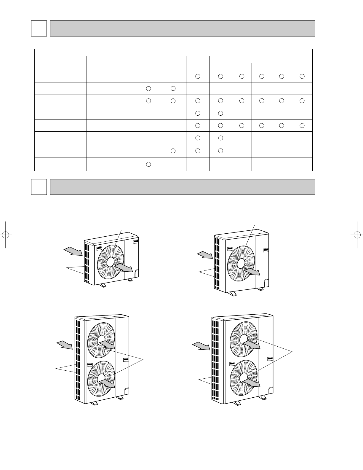
1 COMBINATION OF INDOOR AND OUTDOOR UNITS
Air intake
Air outlet
(Expels warm air during cooling)
Air intake
Air outlet
Air intake
Air outlet
Air intake
Air outlet
Indoor unit Outdoor unit
Model Service
Manual No.
PL-AK(S)C
PL-AK(S)D
PL-KJD OC233
PC-GJ(S)D OC215
OC227
PU-2.TH PU-2.5.TH PU-3.TH PU-4.TH PU-5.TH PU-6.TH
NJA NJA NJA TJSA TJSA XJSA TJSA XJSA
——
——————
PE-EJH(S)A OC131
PE-EJ(S)A OC155
PS-GJ(S
PK-FL(S)D OC232
PK-2GKLD OC228
)
OC143
—— ————
——
—— ————
—————
———————
2 PART NAMES AND FUNCTIONS
●Outdoor Unit
PU-2NJA.TH
PU-2.5NJA.TH
PU-3NJA.TH
wUnit of pressure is based on ISO (International Standardization Organization)
[kgf/cm
2
]➝[MPa] (1MPa=10.2kgf/cm2)
PU-4TJSA.TH
PU-5XJSA.TH
PU-5TJSA.TH
PU-6XJSA.TH
PU-6TJSA.TH
2
Page 3
3 DATA
●JIS B8616
Indoor 27:(80°F)D.B.,19:(66°F)W.B.
Outdoor 35:(115°F)D.B.,24:(75°F)W.B.
Power supply N:220V(1phase) 60Hz T:220V(3phase) 60Hz
Service Ref PU-2NJA.TH PU-2.5NJA.TH PU-3NJA.TH PU-4TJSA.TH PU-5TJSA.TH PU-6TJSA.TH
Current A 11.4 13.4 17.6 12.2 16.83 18.7
Input kW 2.45 2.91 3.44 4.27 5.63 6.15
Starting current A 54 58 80 69 135 140
Power supply X:380V(3phase) 60Hz
Service Ref PU-5XJSA.TH PU-6XJSA.TH
Current A 8.69 9.35
Input kW 5.12 5.71
Starting current A 64 70
●SSA 385,386
Indoor 29:(84°F)D.B.,19:(66°F)W.B
Outdoor 46:(115°F)D.B.,24:(75°F)W.B.
Power supply N:220V(1phase) 60Hz T:220V(3phase) 60Hz
Service Ref PU-2NJA.TH PU-2.5NJA.TH PU-3NJA.TH PU-4TJSA.TH PU-5TJSA.TH PU-6TJSA.TH
Current A 13.6 15.8 20.9 14.0 19.61 21.45
Input kW 2.97 3.44 4.09 4.97 6.68 7.28
Starting current A 54 58 80 69 135 140
Power supply Service Ref.(inddor unit
)
Model name (Outdoor unit)/Service Ref.
PU-2 PU-2.5 PU-3 PU-4 PU-5 PU-6
60Hz
1ph 220V
PU-2NJA.TH
PU-2.5NJA.TH PU-3NJA.TH — — —
3ph
220V — — — PU-4TJSA.TH PU-5TJSA.TH PU-6TJSA.TH
380/220V — — — — PU-5XJSA.TH PU-6XJSA.TH
Notes:1.Powert supply key
N····1ph, 220V, 60Hz
T···· 3ph, 220V, 60Hz
X···· 3ph, 380/220V, 60Hz, 4 wires
Compressor
Winding resistance
(")
at20:Outdoor unit
R-C/U-V S-C/V-W W-U Service Ref.
NHJ33NBDT 0.92 1.93 — PU-2NJA.TH
NHJ38NBDT 0.83 1.83 — PU-2.5NJA.TH
NHJ47NADT 0.55 1.24 — PU-3NJA.TH
NHJ56TKAT 0.87 0.87 0.87 PU-4TJSA.TH
Compressor
Winding resistance
(")
at20:Outdoor unit
T1-T2 T2-T3 T3-T1 Service Ref.
ZR-61KC-TF5
0.628-0.722 0.628-0.722 0.628-0.722 PU-5TJSA.TH
ZR-61KC-TF7
2.23 2.23 2.23 PU-5XJSA.TH
ZR-68KC-TF5
0.517 0.517 0.517 PU-6TJSA.TH
ZR-68KC-TF7
1.92 1.92 1.92 PU-6XJSA.TH
1. ELECTRICAL SPECIFICATIONS
(1) Rating conditions
2.POWER SUPPLY & MODEL NAMES
3.COMPRESSOR TECHNICAL DATA
3
Page 4
4. ADDITIONAL REFRIGERANT CHARGE (R-22
Outdoor unit
precharged (kg)
(up to 20m)
Service Ref.
Refrigerant piping length (one way)
PU-2NJA.TH
PU-2.5NJA.TH
PU-3NJA.TH
PU-4TJSA.TH
1.9
2.4
3.5
4.6
20m (66ft) 25m (82ft) 30m (98ft) 35m (115ft) 40m (131ft)
0
0
0
0
0.06 (0.13)
0.06 (0.13)
0.06 (0.13)
0.15 (0.33)
––
––
––
0.45 (0.99) 0.6 (1.32)
45m (148ft)
–
–
–
–
50m (164ft)
–
–
–
–
0.12 (0.26)
0.12 (0.26)
0.12 (0.26)
0.30 (0.66)
PU-5XJSA.TH
5.1
0 0.15 (0.33) 0.45 (0.99) 0.6 (1.32) 0.75 (1.65) 0.9 (1.98)0.30 (0.66)
PU-5TJSA.TH
5.1
0 0.15 (0.33) 0.45 (0.99) 0.6 (1.32) 0.75 (1.65) 0.9 (1.98)0.30 (0.66)
PU-6XJSA.TH
5.7
0 0.15 (0.33) 0.45 (0.99) 0.6 (1.32) 0.75 (1.65) 0.9 (1.98)0.30 (0.66)
PU-6TJSA.TH
5.7
0 0.15 (0.33) 0.45 (0.99) 0.6 (1.32) 0.75 (1.65) 0.9 (1.98)0.30 (0.66)
……
kg (lbs))
4
Page 5

4 OUTLINES AND DIMENSIONS
100 10
1000For 10 units or less
200
Outdoor Unit-necessary surrounding clearance
(Concentrated installation)
The upper side must be open.
Outdoor Unit-necessary surrounding clearance
200
10
10
10
Note:Allow adequate
upper clearance
150
500
500
Service space
Front opening
Handle
for moving
138
95
Rear piping hole
23
33
Rear fresh
air intake
Side air intake
7 24(1)295(11-5/8)
Outlet guide
installation hole
302
Air intake
Air intake
Air outlet
870(34-1/4)
185
(7-9/32)
185
(7-9/32)
500(19-11/16)
330(13)
362(14-1/4)
1715
39.5 27.5
Terminal block for indoor and outdoor unit connection
Terminal block for power line
Handle for moving
77
524
339
282
297
444
650 (25-5/8)
40 60524
Service panel
(Ground terminal)
Refrigerant-pipe flared
connection
[15.88 3/8F
Refrigerant-pipe flared
connection
[9.52 3/8F
Knock out hole
for front piping
(refrigerant,drainage
and wiring)
Knock out hole
for front piping
(refrigerant,drainage
and wiring)
R
20
R20
60
120
4553
25 max.
Knock out holes for
power line 2-[27
Standard bolt length
65
Front right piping holes-
detail figures
80
17
42
45
12
R6
104
33
Bottom
piping hole
2-U-shaped
notched
holes
Drain hole
Drain hole
2-12o23 Oval holes
(standard bolt M10)
Handle for moving
PU-2NJA.TH
Unit : mm (inch)
5
Page 6
PU-2.5NJA.TH
100 10
1000For 10 units or less
200
Outdoor Unit-necessary surrounding clearance
(Concentrated installation)
The upper side must be open.
Outdoor Unit-necessary surrounding clearance
200
10
10
10
Note:Allow adequate
upper clearance
150
500
500
Service space
Front opening
Handle
for moving
138
95
Rear piping hole
23
33
Rear fresh
air intake
Side air intake
7 24(1)295(11-5/8)
Outlet guide
installation hole
302
Air intake
Air intake
Air outlet
870(34-1/4)
185
(7-9/32)
185
(7-9/32)
500(19-11/16)
330(13)
362(14-1/4)
1715
39.5 27.5
Terminal block for indoor and outdoor unit connection
Terminal block for power line
Handle for moving
179 524
441
337
352
403
553
850(33-7/16)
40 60524
Service panel
(Ground terminal)
Refrigerant-pipe flared
connection [15.88 5/8F
Refrigerant-pipe flared
connection [9.52 3/8F
Knock out hole
for front piping
(refrigerant,drainage
and wiring)
Knock out hole
for front piping
(refrigerant,drainage
and wiring)
R
20
R20
60
120
4553
25 max.
Knock out holes for
power line 2-[27
Standard bolt length
65
Front right piping holes-
detail figures
80
17
42
45
12
R6
104
33
Bottom
piping hole
2-U-shaped
notched
holes
Drain hole
Drain hole
2-12o23 Oval holes
(standard bolt M10)
Handle for moving
PU-3NJA.TH
Unit : mm (inch)
6
Page 7
PU-4TJSA.TH
300
Outdoor Unit-necessary surrounding clearance
Note:Allow adequate
upper clearance
10
Front opening
10
1715
185
(7-9/32)
150
500
Service space
500
10
Terminal block for
indoor and outdoor
unit connection
362(14-1/4)
330(13)
39.5 27.5
(Ground terminal)
Terminal block for power line
Service panel
Handle
for moving
Refrigerant-pipe flared
1258(49-1/2)
959
4553
Knock out holes for
60
connection [19.05 3/4F
Refrigerant-pipe flared
connection [9.52 3/8F
Knock out hole
for front piping
403
382
power line 2-[27
120
(refrigerant,drainage
104
Knock out hole
for front piping
and wiring)
57
52
39
R20
R20
(refrigerant,
Bottom
Unit : mm (inch)
Standard bolt length
25 max.
80
65
Front right piping holes-
17
R6
drainage and wiring)
piping hole
2-U-shaped
notched
holes
detail figures
12
Air intake
500(19-11/16)
185
(7-9/32)
Air intake
300
1000For 10 units or less
The upper side must be open.
870(34-1/4)
302
Air outlet
Outlet guide
7 24(1)295(11-5/8)
installation hole
Side air intake
52461
585
Handle for moving
Rear fresh
air intake
345
2-12o23 Oval holes
(standard bolt M10)
83 524
40 60524
Drain hole
33
23
Drain hole
Outdoor Unit-necessary surrounding clearance
(Concentrated installation)
150 10
Handle
for moving
7
Rear piping hole
95
138
Page 8
PU-5TJSA.TH PU-6TJSA.TH
150 10
1000For 10 units or less
300
Outdoor Unit-Necessary surrounding clearance
(Concentrated installation)
Outdoor Unit-Necessary surrounding clearance
The upper side must be open.
Handle
for moving
138
95
Rear piping hole
23
33
Rear fresh
air intake
Side air intake
7 24(1)345(13-9/16)
Outlet guide
installation hole
352
Air intake
Air intake
Air outlet
970(38-3/16)
185
(7-9/32)
185
(7-9/32)
600(23-5/8)
380(14-31/32)
412(16-1/4)
1715
39.5 27.5
Terminal block for
indoor and outdoor
unit connection
Terminal block for power line
300
10
10
10
Note:Allow adequate
upper clearance
150
500
500
Service space
Handle for moving
52461
585
83 524
345
382
403
959
1258(49-1/2)
90 60524
Service panel
(Ground terminal)
Handle
for moving
Refrigerant-pipe flared
connection [19.05 3/4F
Refrigerant-pipe flared
connection [9.52 3/8F
Knock out hole
for front piping
(refrigerant,drainage
and wiring)
Knock out hole
for right piping
(refrigerant,
drainage and wiring)
R
20
R20
60
120
4553
25 max.
Knock out holes for
power line 2-[27
Standard bolt length
65
Front right piping holes-
detail figures
80
17
52
57
12
R6
104
39
Bottom
piping hole
2-U-shaped
notched
holes
Drain hole
Drain hole
2-12o23 Oval holes
(standard bolt M10)
Front opening
PU-5XJSA.TH PU-6XJSA.TH
Unit : mm (inch)
8
Page 9
5 WIRING DIAGRAM
WHT
BLU
BRN
YLW
WHT
49F4
MF4
MF3
MC
BLU
RED
ORN
4
2
1
3
WHT
YLW
YLW
GRY
GRY
C
HC
9695
47
51C
52C
13
32
31
14
63L
26C
63H
A1
A2
A
WHT
REDTB3
1
1
2
2
BP1 P3P3
X17
X6
X6
X17X14
X14
CP
P2
52C 52C
52C
52
C
F3
(5A)
WHT
WHT
BRN
VLT
VLT
GRY
GRY
RED
ORN
YLW
WHT
BLU
RED
ORN
WHT
BLU
BLU
C3
C4
RED
WHT
BLK
GRY
RED
WHT
BLU
RED
TB1
TB1
26C
47
49F3,4
51C
52C
63H
63L
CP
C3,4
F3
HC
MC
MF3,4
POWER SUPPLY TERMINAL BLOCK
LINE TERMINAL BLOCK
TB3 INDOOR/OUTDOOR CONNECTING
THERMAL SWITCH
ANTI-PHASE PROTECTOR
FAN MOTOR INTERNAL THERMOSTAT
THERMAL RELAY
COMPRESSOR CONTACTOR
HIGH PRESSURE SWITCH
LOW PRESSURE SWITCH
COMPRESSOR PROTECTOR
FAN MOTOR CAPACITOR
FUSE(5A)
CRANKCASE HEATER
COMPRESSOR
FAN MOTOR
NOTES:1.THE DOTTED LINES SHOW FIELD WIRING.
2. TO INDOOR UNIT TERMINAL BLOCK.
POWER SUPPLY
3~
220V 60Hz
L1
L2
L3
GRN/
YLW
T3/6
T2/4
T1/2
L3/5
RST
47
L2/3
L1/1
51C
52C
WHT
49F3
BLU
RED
ORN
4
U
2
1
3
V
W
A
PU-2NJA.TH PU-2.5NJA.TH
POWER
SUPPLY
~/N
220V 60z
PU-3NJA.TH
TB3
POWER
SUPPLY
~/N
220V 60Hz
TB3
TB1
RED
1
2
WHT
N
L
(5A)
RED
1
2
WHT
F3
TB1
L
N
F3
(5A)
GRN/YLW
RED
YLW
A
1
2
GRY
P1
P1
X6
L1/1
L3/5
HC
22
21
13 14
GRY
52C
X6
X6
52C
L1/1
T1/2
WHT
P3 P3
T1/2
T3/6
GRY
BLUT3/6
C3
63L
WHT
WHT
GRY
P2
X17
CP
BLU
WHT
C3
63L
WHT
WHT
P2
CP
X17
L3/5
63H
GRY
52C
52C
X6
52C
63H
52C
VLT
VLT
52C
P3 P3
RED
BLU
GRN/YLW
BLU
RED
A1
52
C
A2
YLW
ORN
A
B
X14
1
X17X14
2
WHT
BLU
BLU
GRY
52C
A1
52
C
A2
ORN
B
X14
X17X14
WHT
ORN
BLU
BLU
RED
WHT
49C
C
C
S
RED
R
BLU
WHT
3
ORN
1
REDRED
2
BLU
4
BLU
C
RED
BLU
4
RED
2
ORNORN
1
3
WHT
S
C
49C
49F3
R
MC
MF3
MC
MF3
49F3
C
COMPRESSOR RUN CAPACITOR
CP
COMPRESSOR PROTECTOR
C3
FAN MOTOR CAPACITOR
F3
FUSE(5A)
MC
COMPRESSOR
MF3
FAN MOTOR
TB1
POWER SUPPLY TERMINAL BLOCK
TB3
INDOOR/OUTDOOR CONNECTING LINE TERMINAL BLOCK
49C
COMPRESSOR INTERNAL THERMOSTAT
49F3
FAN MOTOR INTERNAL THERMOSTAT
52C
COMPRESSOR CONTACTOR
63H
HIGH PRESSURE SWITCH
63L
LOW PRESSURE SWITCH
NOTES:1.THE DOTTED LINES SHOW FIELD WIRING.
2. TO INDOOR UNIT TERMINAL BLOCK.
C
COMPRESSOR RUN CAPACITOR
CP
COMPRESSOR PROTECTOR
C3
FAN MOTOR CAPACITOR
F3
FUSE(5A)
HC
CRANKCASE HEATER
MC
COMPRESSOR
MF3
FAN MOTOR
TB1
POWER SUPPLY TERMINAL BLOCK
TB3
INDOOR/OUTDOOR CONNECTING LINE TERMINAL BLOCK
49C
COMPRESSOR INTERNAL THERMOSTAT
49F3
FAN MOTOR INTERNAL THERMOSTAT
52C
COMPRESSOR CONTACTOR
63H
HIGH PRESSURE SWITCH
63L LOW PRESSURE SWITCH
NOTES:1.THE DOTTED LINES SHOW FIELD WIRING.
2. TO INDOOR UNIT TERMINAL BLOCK.
PU-4TJSA.TH
9
Page 10

PU-5TJSA.TH PU-6TJSA.TH
96
95
51C
A
C
47
51C
T1/2
T2/4
T3/6
TB1
26C
63H
GRY
63L
GRY
BLK
WHT
CIRCUIT
BREAKER
BLU
49C
49C
49C
GRN/YLW
N
POWER SUPPLY
3N~ (3PHASE 4WIRES)
380V 60Hz
L1
L2
L3
BLK
WHT
RED
F3
(5A)
BLU
RED
A1
A2
14
13
52C
GRY
RED
WHT
GRY
RED
BLK
YLW
47
RTS
RED
WHT
BLK
L3/5
L2/3
L1/1
52C
52
C
T3
T2
T1
BLK
WHT
RED
MF4
49F4
WHT
ORN
RED
BLU
WHT
ORN
RED
BLU
MC
MF3
49F3
C4
C3
WHT
ORN
RED
BLU
BLU
RED
ORN
WHT
3
1
2
4
3
1
2
4
CP
X17
X6
X14
P2P3P3
52C
52C
P1
BA
WHT
RED
TB3
X6
2
1
1
2
X17
X14
THERMAL RELAY51C
LOW PRESSURE SWITCH63L
PHASE PROTECTOR47
INTERNAL THERMOSTAT FOR MC49C
NOTES: 1.THE DOTTED LINES SHOW FIELD WIRING.
2. TO INDOOR UNIT TERMINAL BLOCK.
TERMINAL BLOCK (CONNECTING WIRES INDOOR/OUTDOOR)
CP
TERMINAL BLOCK (POWER SUPPLY)
COMPRESSOR
FAN MOTOR
FUSE (5A)
FAN MOTOR CAPACITOR
HIGH PRESSURE SWITCH
COMPRESSOR CONTACTOR
INTERNAL THERMOSTAT FOR MF3,4
THERMAL SWITCH
COMPRESSOR PROTECTOR
63H
52C
49F3,4
26C
TB3
TB1
MF3,4
MC
F3
C3,4
POWER SUPPLY
3~ (3PHASE)
220V 60Hz
CIRCUIT
BREAKER
TB3
TB1
RED
L1
L2
L3
F3
(5A)
RED
1
*
2
*
WHT
1
2
RED
YLW
X14
A1
52
A2
WHT
BLK
GRN/YLW
WHT
C
GRY
X17X14
RED
RTS
51C
52C
RED
BLK
52C
P1BA
X6
X6
52C
95
96
L1/1
L2/3
L3/5
WHT
63L
1413
BLK
GRY
RED
52C
47
GRY
26C
63H
X17
WHT
P2P3P3
51C
47
T1/2
T2/4
T3/6
BLK
GRY
RED
WHT
T2
49C
BLK
BLU
BLU BLU
WHT
RED
C3
ORN
A
C
WHT
BLU
RED
C4
ORN
WHT
CP
C3,4
CP
F3
T3
4
RED
2
ORN
1
WHT
3
BLU
4
RED
2
ORN
1
WHT
3
COMPRESSOR PROTECTOR
FAN MOTOR CAPACITOR
FUSE(5A)
T1
MC
49C
49C
MF3
49F3
MF4
49F4
PHASE PROTECTOR47
MC
MF3,4
TB1
TB3
26C
COMPRESSOR
FAN MOTOR
TERMINAL BLOCK(POWER SUPPLY)
TERMINAL BLOCK
(CONNECTING WIRES INDOOR/OUTDOOR)
THERMAL SWITCH
INTERNAL THERMOSTAT FOR MC49C
49F3,4
52C
63H
INTERNAL THERMOSTAT FOR MF3,4
COMPRESSOR CONTACTOR
HIGH PRESSURE SWITCH
LOW PRESSURE SWITCH63L
THERMAL RELAY51C
NOTES: 1.THE DOTTED LINES SHOW FIELD WIRING.
2.* TO INDOOR UNIT TERMINAL BLOCK.
PU-5XJSA.TH PU-6XJSA.TH
10
Page 11

6 REFRIGERANT SYSTEM DIAGRAM
Low pressure
switch
Charge
plug
Ball
valve
[15.88
(5/8)
Ball valve
(with service port)
Accumulator
[9.52
(3/8)
O.D.3.2oI.D.2.0-L430
Check
plug
Compressor
Capillary tube
O.D.3.2oI.D.1.2
-L1000
Capillary tube
for injection
Strainer
#100
Outdoor heat
exchanger
High pressure
switch
flow of refrigerant
Charge
plug
Ball
valve
Ball valve
(with service port)
Accumulator
[9.52
(3/8)
Compressor
Capillary tube for
injection
#100
Strainer
Outdoor heat
exchanger
Check
plug
flow of refrigerant
Low pressure
switch
High pressure
switch
[15.88
(5/8)
w
Capillary
tube
PU-2.5
(O.D.3.2oI.D.1.6
-L760)o2pcs
PU-3
(
O.D.3.2oI.D.1.8
-
L800)o2pcs
PU-2.5 (O.D.3.2oI.D.1.2-L1000)
PU-3 (O.D.3.2oI.D.1.6-
L500
)
Charge
plug
Ball
valve
[19.05
(3/4)
Ball valve
(with service port)
Accumulator
[9.52
(3/8)
Compressor
Capillary tube for
injection
Strainer
#100
Outdoor heat
exchanger
Check
plug
flow of refrigerant
Low pressure
switch
High pressure
switch
w
Capillary
tube
O.D.3.2oI.D.2.0
-L840o2pcs
O.D.3.2oI.D.1.2-L500
Outdoor heat
exchanger
Ball
valve
Ball valve
(with service port)
High pressure
switch
Compressor
Accumulator
DPR
Capillary tube
PU-5 (O.D. 4.0 oI.D. 2.4 oL400)
PU-6 (O.D. 4.0 oI.D. 2.4 oL200)
Capillary tube
PU-5
(O.D. 4.0 oI.D. 2.4 oL840)o2pcs
PU-6
(O.D. 4.0 oI.D. 2.4 oL740)o2pcs
[9.52
(3/8)
[19.05
(3/4)
Check plug
Charge
plug
: flow of refrigerant
Strainer #100
Low pressure
switch
Strainer
#50
DPR : Discharge pressure
regulator
PU-2NJA.TH
PU-2.5NJA.TH
PU-3NJA.TH
PU-4TJSA.TH
PU-5TJSA.TH PU-6TJSA.TH
PU-5XJSA.TH PU-6XJSA.TH
11
Page 12

7
TROUBLE SHOOTING
7-1. SELF-DIAGNOSTIC FUNCTION
7-1-1. Wired remote controller (1)
! When trouble occurs during operation, the unit stops and enters the self-diagnostic mode, and displays the trouble loca-
tion with the timer lamps on the remote controller. All the other lamps are OFF.
@ To activate the self-diagnostic function for service, press the UP and DOWN buttons simultaneously for more than two
TEMP.
seconds during operation with lamp ON.
# The timer lamps show the latest trouble. Trouble data is memorized until the next trouble occurs, even when the breaker
turns OFF. To clear the memory, press the UP and DOWN buttons simultaneously for more than two seconds during the
test run.
$ All buttons except the POWER ON/OFF button are unavailable during the self-diagnostic mode.
% To release the self-diagnostic mode, press the POWER ON/OFF button.
Unit
Transmission error
Unit
No.1
Unit
No.2
Unit
No.1
Unit
No.2
Unit
No.1
Unit
No.2
Unit
No.1
Unit
No.2
Unit
No.1
Unit
No.2
12
12
11
11
10
10
9
9
8
8
7
7
6
6
5
5
4
4
3
3
2
2
1
1
TIMER
▲
TEMP.
29
29
28
28
27
27
26
26
25
25
24
24
23
23
22
22
21
21
20
20
19
19
18
18
▲
▲
Trouble location
in twin control
Outdoor unit
Room
temperature
thermistor
(RT1)
Indoor coil
thermistor
(RT2)
Drain sensor
(DS)
Drain
overflow
protection
Coil frost
or overheat
prevention
Cause
●Wrong wiring between No. 1
and No. 2 units
●Poor connector contact
●Wrong wiring between
indoor/outdoor units
●Outdoor unit abnormality
detection
●Malfunction of outdoor coil
thermistor
●Reversed phase detected
●Poor connector contact
●Thermistor malfunction
●Poor connector contact
●Thermistor malfunction
●Poor connector contact
●Thermistor malfunction
●Drain pump malfunction
●Drain sensor improperly
mounted
●Air passage short cycle
●Air filter clogged
●Indoor fan malfunction
Measures
●Check dip switch setting
●Check wiring
●Check wiring
●Check outdoor unit
●Check outdoor coil thermistor
●Check connector
●Check thermistor
➔ No trouble ➔ replace indoor
●Check connector
●Check thermistor
➔ No trouble ➔ replace indoor
●Check connector
●Check thermistor
➔ No trouble ➔ replace indoor
●Check drain pump
●Check drain sensor
➔ No trouble ➔ replace indoor
●Remove blockage
●Check air filter
●Check indoor fan
}
controller
board.
}
controller
board.
}
controller
board.
}
controller
board.
(Indicates that the unit is in self-diagnostic mode)
12
Page 13

7-1-2. WIRED REMOTE CONTROLLER(2)
1) When malfunction occurs during operation
When a malfunction occurs, the indoor and outdoor units stop and the malfunction is displayed on the LCD of the remote
controller.
(1) ON the set temperature display part, “CHECK” appears, and the unit
address and the check code are displayed alternately at one-second
intervals. (Check mode)
Example
CHECK mode
Check
code
Unit
address
(2) When one remote controller controls several units in the group con-
trol, the LCD shows the unit address and check code of the first malfunctioning unit.
(3) To cancel the check mode, press the ON/OFF button. In remote
ON/OFF control, press the remote ON/OFF switch. In centralized
control, turn OFF the ON/OFF button of centralized controller.
Check button
NOTE: The latest check code is memorized, even if the check mode is cancelled by the way mentioned above. It takes
60 seconds maximum to display the memorized check code.
2) How to use the self diagnostic function for service
A. For normal control with one unit and one remote controller
(1) Pressing the CHECK button on the remote controller twice starts the self diagnostic function.
(2) During the self diagnostic function, “CHECK MODE” appears at two positions on the remote controller display. Then, at
least 10 seconds later, the unit address and the check code is alternately displayed at one-second intervals.
(3) Check and repair the unit according to the check code.
B. For group control using one remote controller
(1) Pressing the CHECK button on the remote controller twice starts the self diagnostic function.
(2) Press the TEMP. button or TEMP. button on the remote controller to advance or go back to the unit address.
Each time TEMP. button is pressed, the unit address advances by one. Each time TEMP. button is pressed,
▲
▲ ▼
▼
the unit address goes back by one.
The check code and the unit address, appear alternately.
(3) The check code “U8” means no malfunction has occurred since installation.
The check code “EO” means the following conditions:
● The unit address displayed on the remote controller does not apply to any unit.
● power is not supplied to the unit.
● Signal transmitting/receiving circuit is abnormal.
(4) Check and repair the unit according to the check code.
13
Page 14

Check
code
(P1)
(P2)
Diagnosis of malfunction Cause Check points
Abnormality of room temperature thermistor (RT1)
Abnormality of indoor coil
thermistor (RT2)
1) Bad contact of thermistor
2) Damaged thermistor
1) Check the thermistor.
2) Measure the resistance of the thermistor.
Normal resistance should be as follows.
0°C···15kΩ 30°C····4.3kΩ
10°C·····9.6kΩ 40°C·····3.0kΩ
20°C·····6.3kΩ
If the resistance is normal, replace the indoor
controller board.
(P4) Abnormality of drain sensor 1) Bad contact of transmission
(P5) Malfunction of drain pump 1) Malfunction of drain pump
(P6) Coil frost protection is work-
ing.
(P8) Abnormality in outdoor unit 1) Wrong wiring of indoor/outdoor
wire
2) Damaged thermistor
2) Damaged drain sensor
1) Short cycle of air cycle
2) Dirty air filter
3) Damaged fan
4) Abnormal refrigerant
connecting wire
2) Reversed phase
3) Protection device is working
4) Damaged outdoor coil thermistor
1) Check the connector.
2) Measure the resistance of the thermistor 4 ~
5.
As for the normal resistance, refer to the case
of P1.
If the resistance is normal, replace the indoor controller board.
1) Check the drain pump.
2) ● Check the drain sensor.
● Check the drain sensor heater. Normal resistance should be 82Ω.
If the resistance is normal, replace the indoor controller board.
1) Clear obstructions from the air cycle.
2) Clean the air filter
3) Check the fan.
4) Check the refrigerant temperature.
1) Check the indoor/outdoor connecting wire.
2) Change the connection of electric wiring.
3) Check the protection device.
4) Measure the resistance of the outdoor coil thermistor. If the resistance is normal, replace the
outdoor controller board.
14
Page 15

7-2. HOW TO CHECK THE PARTS
Check points
FAN MOTOR
Parts name
Measure the resistance between the terminals using a tester.
(
MF3,MF4
)
(Surrounding temperature
20:
)
Motor lead wire
Normal
Abnormal
2,2.5,3N 4T 5,6T,X
White-Blue 68.8" 74.6" 91.3"
Open or short
Blue-Red(Brown
)
88.4" 122.0" 96.0"
Protector
OPEN:145I8:
CLOSE:90I15:
CRANK CASE
Measure the resistance between the terminals using a tester.
HEATER(HC
)
Normal
Abnormal
3N 4T
1274" 1274" Open or short
COMPRESSOR 1Winding resistance
(")
(MC)
Measure the resistance between the terminals using a tester.
(
Surrounding temperature20:
)
Terminals
Normal
Abnormal
2N 2.5N 3N 4T
R-C(U-V
)
0.92" 0.83" 0.55" 0.87"
Open or short
S-C(V-W
)
1.933" 1.83" 1.24" 0.87"
W-U — — — 0.87"
Terminals
Normal
Abnormal
5T 5X 6T 6X
T1-T2 0.628-0.722" 2.23" 0.517" 1.92"
Open or short
T2-T3 0.628-0.722" 2.23" 0.517" 1.92"
T3-T1 0.628-0.722" 2.23" 0.517" 1.92"
2
Internal thermostat motor protection (49C)
Internal
thermostat
motor protection
PU-4T PU-5T PU-5X PU-6T PU-6X
NH56TKAT
TF5
ZR-61KC-
TF7
ZR-61KC-
TF5
ZR-68KC-F7ZR-68KC-T
Opening temp. 125I5: 120I5: 120I5: 120I5: 120I5:
Closing temp. 90I7: 90I15: 90I15: 90I15: 90I15:
PU-2NJA.TH
PU-2.5NJA.TH
PU-3NJA.TH
PU-4TJSA.TH
PU-5TJSA.TH PU-5XJSA.TH
PU-6TJSA.TH PU-6XJSA.TH
15
Page 16

8 DISASSEMBLY PROCEDURE
OUTDOOR UNIT PU-3NJA.TH
OPERATING PROCEDURE PHOTOS
1. Removing the electrical parts
(1)
Remove the 5 screws and the top panel. (3 screws in
front and 2 screws in rear
(2)
Remove the screw of the cover panel. To remove the
cover panel, pull it toward you and unhook the catches from the side panel.
(3)
Remove the screw of the service panel. To remove the
service panel, pull it down toward you and unhook the
catches on the both sides.
)
Photo 1
Photo 2
Screws
Front panel
Compressor
protector
Top panel
Service panel
Panel cover
Capacitor
Contactor
2. Removing the fan motor
(1)
Remove the 3 screws of the front panel. Open the
front panel to a 45-degree angle. Then lift it and
unhook the 3 catches to remove.
(2)
Remove the propeller nut and the propeller.
(3)
Remove the 3 screws and the fan motor.
Disconnect the lead connectors.
Photo 3
Propeller
16
Terminal blockScrews
Motor support
Propeller nut Crankcase heater
Separator support plate
High-pressure control
Lead
connectors
Valve bed
switch
Page 17

OPERATING PROCEDURE PHOTOS
3. Removing the heat exchanger and the compressor
(1)
Remove the rear panel (2 screws in front, 1 screw on
the side, 3 screws in the rear). Remove the valve bed,
and open the rear panel to the rear to remove.
NOTE :
All panels are fixed by catches, and must be removed by
shifting up and down.
(2)
Remove the 4 screws of the right side panel and
remove it.
(3)
Remove the 3 screws of the rear guard and remove
the rear guard.
(4)
Remove the 4 screws of the separator support plate
and remove the separator support plate .
(5)
Remove the 2 screws of the motor support and
remove the motor support.
(6)
Remove the 5 screws of the valve bed.
The valve bed is fixed by the catches on the right and
left sides.
Lift it to remove.
(7)
Remove the electrical parts box.
Disconnect the connectors from the high pressure
switch, crank case heater, shell thermo, and fan motor
lead.
(8)
Remove the 2 screws of the separator and remove the
separator.
(9)
Remove the 2 screws of the heat exchanger and
remove the heat exchanger.
Detach the welded point of pipe.
)
(
Remove the 3 nuts of the compressor and remove the
10
compressor.
Detach the welded points of the compressor suction
pipe and discharge pipe.
Photo 4
Screws
Screws
Photo 5
Heat exchanger
Accumulator
Photo 6
Charge plug
Ball valve
Compressor
17
Page 18

9 PARTS LIST
1
2
3
4
5
6
7
8
9
10
11
12
13
Part No. Part Name
SpecificationNo.
Q,ty/set
Wiring
Diagram
Symbol
Recom-
mended
Q,ty
Price
Unit
Amount
SCREW
LEFT SIDE PANEL
HANDLE
FRONT PANEL
FAN GUARD
MOTOR SUPPORT
BASE
SERVICE PANEL
PANEL COVER
REAR PANEL
LABEL
REAR GUARD
TOP PANEL
13
1
3
1
1
1
1
1
1
1
1
1
1
Remarks
(BG00N264G06)
(JG79C180H02)
(5o10)
NJA.TH
PU-2
—
E07 001 249
E07 001 009
E07 001 232
E07 001 521
—
E07 003 290
E07 001 245
E07 001 006
E07 001 522
—
E07 001 523
E02 214 297
(Z004M203H10)
13Pcs/set
STRUCTURAL PARTS
PU-2NJA.TH
13 12
11 103
1
2
3
4
5
7689
18
Page 19

STRUCTURAL PARTS
1
2
3
4
5
6
7
8
9
10
11
12
13
Part No. Part Name
SpecificationNo.
Wiring
Diagram
Symbol
Recom-
mended
Q,ty
Price
Unit
Amount
SCREW
LEFT SIDE PANEL
FRONT PANEL
HANDLE
FAN GUARD
BASE
MOTOR SUPPORT
SERVICE PANEL
PANEL COVER
REAR PANEL
LABEL
REAR GUARD
TOP PANEL
13
1
1
3
1
1
1
1
1
1
1
1
1
Remarks
(5o10)
NJA.TH
PU-2.5, 3
—
E02 214 249
E07 003 232
E07 001 009
E02 527 521
E07 003 290
—
E07 003 245
E07 001 006
E07 003 522
—
E07 003 523
E02 214 297
(SU02Y704G04)
(JG79C180H02)
(Z004M203H10)
13Pcs/set
Q,ty/set
PU-2.5NJA.TH
PU-3NJA.TH
13 12
11104
1
2
3
4
5
67 89
19
Page 20

STRUCTURAL PARTS
Part No. Part Name
SpecificationNo.
Q,ty/set
Wiring
Diagram
Symbol
Recom-
mended
Q,ty
Price
Unit
Amount
SCREW
LEFT SIDE PANEL
FAN GUARD
FRONT PANEL
HANDLE
BASE
SERVICE PANEL
PANEL COVER
REAR PANEL
LABEL
REAR GUARD
TOP PANEL
MOTOR SUPPORT
1
2
3
4
5
6
7
8
9
10
11
12
13
13
1
2
1
3
1
1
1
1
1
1
1
1
Remarks
(5o10)
TJSA.TH
PU-4
—
E07 005 249
E02 527 521
E07 005 232
E07 001 009
E07 005 290
E07 005 245
E07 001 006
E07 005 522
—
E07 005 523
E02 214 297
—
(JG79C180H02)
(BG00N264G08)
(Z004M203H10)
13Pcs/set
PU-4TJSA.TH
12 1113
10 9
1
2
3
4
5
3
5
67
20
8
Page 21

STRUCTURAL PARTS
1
2
3
4
5
6
7
8
9
10
11
12
13
(JG79C180H02)
(BG00N264G08)
Part No. Part Name
SpecificationNo.
Q,ty/set
Wiring
Diagram
Symbol
Recommended
Q,ty
Price
Unit
Amount
Remarks
(Drawing No.)
(5o10)
TJSA.TH
XJSA.TH
PU-5, 6
1
2
3
1
1
1
1
1
1
1
1
13
1
(Z004M203H10)
13Pcs/set
E07 016 232
E02 527 521
E07 001 009
E07 016 290
E07 016 006
E07 016 522
E07 016 245
—
E07 016 523
E07 016 297
—
—
E07 016 249
FRONT PANEL
FAN GUARD
HANDLE
BASE
PANEL COVER
REAR PANEL
SERVICE PANEL
LABEL
REAR GUARD
TOP PANEL
MOTOR SUPPORT
SCREW
LEFT SIDE PANEL
PU-5TJSA.TH PU-6TJSA.TH
PU-5XJSA.TH PU-6XJSA.TH
1
13
12
11
10
9
7
8
6
2
3
5
34
21
Page 22

FUNCTIONAL PARTS
1
2
3
4
5
6
7
8
9
10
11
12
13
14
15
16
17
18
19
20
21
22
FUSE HOLDER
FUSE
COMPRESSOR PROTECTOR
FAN MOTOR
HEAT EXCHANGER
PROPELLER FAN
NUT
CHARGE PLUG
COMPRESSOR
BALL VALVE
BALL VALVE
LOW PRESSURE SWITCH
ACCUMULATOR
HIGH PRESSURE SWITCH
TERMINAL BLOCK
TERMINAL BLOCK
CONTACTOR
FAN MOTOR CAPACITOR
COMPRESSOR CAPACITOR
CAPILLARY TUBE
CAPILLARY TUBE
STRAINER
Part No. Part Name Specification
No.
Q,ty/set
PU-2
NJA.TH
Price
Unit
Amount
250V 5A
230V
PK6V85-UA
M8
NHJ33NBDT
3/8˝ (LIQ)
5/8˝ (GAS)
CUT 0.05MPa
CUT 3.3MPa
3P(L,N,;)
2P(1,2)
S-N20 200VAC
2.5+ 440V
50+ 440V
{3.2o{1.2o1000
{3.2o{2.0o430
1
1
1
1
1
1
1
2
1
1
1
1
1
1
1
1
1
1
1
1
1
1
Remarks
F3
CP
MF3
MC
63L
63H
TB1
TB3
52C
C3
C
E07 001 241
E07 001 382
E07 197 330
E07 011 301
E07 002 630
E07 001 501
E07 070 508
E07 001 641
E07 190 900
E02 010 662
E07 001 661
E07 001 647
E07 002 932
E07 001 646
E07 006 375
E07 002 374
E02 177 342
E02 063 351
E02 946 353
E07 003 937
E07 002 936
E07 002 933
Wiring
Diagram
Symbol
Recommended
Q,ty
PU-2NJA.TH
1
2
3
4
5
6
7
Part numbers that are circled are not shown in the figure.
19
18
98
17
16
15
14
13
12
8
11
10
22
Page 23

FUNCTIONAL PARTS
Part No. Part Name Specification
No.
Q,ty/set
NJA.TH
PU-2.5 PU-3
NJA.TH
Wiring
Diagram
Symbol
Recommended
Q,ty
Price
Unit
Amount
Remarks
(Drawing No.)
1
2
3
4
5
6
7
8
9
10
11
12
13
14
15
16
17
18
19
20
21
22
23
1
1
1
1
1
1
1
2
1
1
1
1
1
1
1
1
1
1
1
1
2
1
1
1
1
1
1
1
1
2
1
1
1
1
1
1
1
1
1
1
1
1
1
2
1
TB1
TB3
MF3
MC
MC
HC
63L
63H
52C
C3
CP
C
F3
E07 001 241
E07 006 375
E07 002 374
E07 003 630
E07 004 630
E07 001 501
E07 070 508
E07 011 301
E07 001 641
E07 191 900
E07 192 900
E07 199 240
E02 010 661
E02 010 662
E07 003 932
E07 001 647
E07 001 646
E02 177 342
E02 138 351
E07 197 330
E02 177 353
E07 001 382
E07 198 933
E07 003 936
E07 070 936
E07 003 937
E07 199 936
FUSE HOLDER
TEAMINAL BLOCK
TEAMINAL BLOCK
HEAT EXCHANGER
HEAT EXCHANGER
PROPELLER FAN
NUT
FAN MOTOR
CHARGE PLUG
COMPRESSOR
COMPRESSOR
CRANKCASE HEATER
BALL VALVE
BALL VALVE
ACCUMULATOR
LOW PRESSURE SWITCH
HIGH PRESSURE SWITCH
CONTACTOR
FAN MOTOR CAPACITOR
COMPRESSOR PROTECTOR
COMP.RUN CAPACITOR
FUSE
STRAINER
CAPILLARY TUBE
CAPILLARY TUBE
CAPILLARY TUBE
CAPILLARY TUBE
3P(L,N,
;)
2P(1,2)
M8
PK6V85-UA
NHJ38NBDT
NHJ47NADT
240V 38W
5/8"(Gas)
3/8"(Liquid)
S-N25EX
3.0µF/440VAC
60µF/440VAC
250V 5A
[3.2O[1.6-L760
[3.2O[1.8-L800
[3.2O[1.2-L1000
[3.2O[1.6-L500
PU-2.5NJA.TH
PU-3NJA.TH
1
2
20
19
18
17
16
15
3
4
5
6
Part numbers that are circled are not shown in the figure.
87
9
23
14
13
8
12
11
10
Page 24

FUNCTIONAL PARTS
1
2
3
4
5
6
7
8
9
10
11
12
13
14
15
16
17
18
19
20
21
22
23
24
TERMINAL BLOCK
TERMINAL BLOCK
FAN MOTOR
HEAT EXCHANGER
PROPELLER FAN
NUT
HIGH PRESSURE SWITCH
CHARGE PLUG
THERMAL SWITCH
COMPRESSOR
CRANKCASE HEATER
BALL VALVE
BALL VALVE
CAPILLARY TUBE
LOW PRESSURE SWITCH
ACCUMULATOR
COMPRESSOR CONTACTOR
ANTI-PHASE PROTECTOR
COMPRESSOR PROTECTOR
FAN MOTOR CAPACITOR
FUSE
FUSE HOLDER
CAPILLARY TUBE
STRAINER
Part No. Part Name Specification
No.
TJSA.TH
Price
Unit
Amount
3P(L,N,;)
2P(1,2)
PK6N60-UA
M8
CUT 3.3MPa
NHJ56TKAT
240V 38W
3/4˝ (GAS)
3/8˝ (LIQ)
{3.2o{2.0o840mm
CUT 0.05MPa
MSO-N25KF 230V AC
230V
4+ 440V AC
250V 5A
{3.2o{1.2o500mm
1
1
2
2
2
2
1
2
1
1
1
1
1
2
1
1
1
1
1
2
1
1
1
1
Remarks
TB1
TB3
MF3,4
63H
26C
MC
HC
63L
51C,52C
47
CP
C3, C4
F3
E07 193 374
E07 002 374
E07 005 301
E07 005 630
E07 001 501
E07 070 508
E07 001 646
E07 001 641
E07 005 308
E07 193 900
E07 200 240
E07 005 661
E02 010 662
E07 005 936
E07 001 647
E07 005 932
E07 193 340
E07 200 344
E07 197 330
E02 064 351
E07 001 382
E07 001 241
E07 005 937
E07 200 933
Wiring
Diagram
Symbol
Recommended
Q,ty
Q,ty/set
PU-4
PU-4TJSA.TH
2122
1
1920
18
17
2
3
4
5
6
Part numbers that are circled are not shown in the figure.
16
15
14
13
12
11
7
8
9
10
24
Page 25

FUNCTIONAL PARTS
Part No. Part Name Specification
No.
Q,ty/set
TJSA.TH
PU-5
PU-6
Wiring
Diagram
Symbol
Recom-
mended
Q,ty
Price
Unit
Amount
Remarks
(Drawing No.)
1
2
3
4
5
6
7
8
9
10
11
12
13
14
15
16
17
18
19
20
21
22
23
24
25
2
2
2
2
1
1
1
1
1
2
2
1
1
1
2
1
1
1
1
1
1
1
1
1
1
2
2
2
2
1
1
1
1
1
2
2
1
1
1
2
1
1
1
1
1
1
1
1
1
1
MF3,4
63H
MC
MC
26C
51C,52C
C3,C4
47
TB1
CP
F3
TB3
63L
FAN MOTOR
HEAT EXCHANGER
HEAT EXCHANGER
PROPELLER FAN
NUT
HIGH PRESSURE SWITCH
COMPRESSOR
COMPRESSOR
BALL VALVE
BALL VALVE
THERMAL SWITCH
CHARGE PLUG
CAPILLARY TUBE
CAPILLARY TUBE
CAPILLARY TUBE
CAPILLARY TUBE
ACCUMULATOR
CONTACTOR
FAN MOTOR CAPACITOR
ANTI-PHASE PROTECTOR
TERMINAL BLOCK
COMPRESSOR PROTECTOR
FUSE
TERMINAL BLOCK
FUSE HOLDER
LOW PRESSURE SWITCH
STRAINER
STRAINER
DIS PRESSURE REGULATOR
E07 194 301
E07 035 630
E07 037 630
E07 001 501
E07 070 508
E07 001 646
E07 194 900
E07 195 900
E07 005 661
E02 010 662
E07 035 308
E07 001 641
E07 016 936
E07 195 936
E07 035 937
E07 037 937
E07 016 932
E07 194 340
E02 064 351
E07 200 344
E07 193 374
E07 197 330
E07 001 382
E07 002 374
E07 001 241
E07 201 647
E07 037 933
E07 015 933
E02 069 644
PK6N65-UA
M8
ZR61KCTF5
ZR68KCTF5
5/8"(GAS)
3/8"(LIQ)
[4.0O[2.4-L840
[4.0O[2.4-L740
[4.0O[2.4-L400
[4.0O[2.4-L200
MSO-N25KF
4.0µ F/440VAC
5P (L1,L2,L3,N,;)
250V 5A
2P (1,2)
PU-5TJSA.TH
PU-6TJSA.TH
19
20
21
1
18
17
16
15
14
13
2
3
1
Part numbers that are circled are not shown in the figure.
2
3
12
11
10
9
4
5
25
6
8
7
Page 26

FUNCTIONAL PARTS
Part No. Part Name Specification
No.
Q,ty/set
XJSA.TH
PU-5
PU-6
Wiring
Diagram
Symbol
Recommended
Q,ty
Price
Unit
Amount
Remarks
(Drawing No.)
1
2
3
4
5
6
7
8
9
10
11
12
13
14
15
16
17
18
19
20
21
22
23
24
25
2
2
2
2
1
1
1
1
1
2
2
1
1
1
2
1
1
1
1
1
1
1
1
1
1
2
2
2
2
1
1
1
1
1
2
2
1
1
1
2
1
1
1
1
1
1
1
1
1
1
MF3,4
63H
MC
MC
26C
52C
C3,C4
47
TB1
CP
F3
TB3
63L
FAN MOTOR
HEAT EXCHANGER
HEAT EXCHANGER
PROPELLER FAN
NUT
HIGH PRESSURE SWITCH
COMPRESSOR
COMPRESSOR
BALL VALVE
BALL VALVE
THERMAL SWITCH
CHARGE PLUG
CAPILLARY TUBE
CAPILLARY TUBE
CAPILLARY TUBE
CAPILLARY TUBE
ACCUMULATOR
CONTACTOR
FAN MOTOR CAPACITOR
ANTI-PHASE PROTECTOR
TERMINAL BLOCK
COMPRESSOR PROTECTOR
FUSE
TERMINAL BLOCK
FUSE HOLDER
LOW PRESSURE SWITCH
STRAINER
STRAINER
DIS PRESSURE REGULATOR
E07 194 301
E07 035 630
E07 037 630
E07 001 501
E07 070 508
E07 001 646
E07 204 900
E07 205 900
E07 005 661
E02 010 662
E07 035 308
E07 001 641
E07 016 936
E07 195 936
E07 035 937
E07 037 937
E07 016 932
E07 204 340
E02 064 351
E07 005 344
E07 005 374
E07 197 330
E07 001 382
E07 002 374
E07 001 241
E07 201 647
E07 037 933
E07 015 933
E02 069 644
PK6N65-UA
M8
ZR61KCTF7
ZR68KCTF7
5/8"(GAS)
3/8"(LIQ)
[4.0O[2.4-L840
[4.0O[2.4-L740
[4.0O[2.4-L400
[4.0O[2.4-L200
MSO-N20KF
4.0µ F/440VAC
5P (L1,L2,L3,N,;)
250V 5A
2P (1,2)
PU-5XJSA.TH
PU-6XJSA.TH
19
20
21
1
18
17
16
15
14
13
2
3
1
Part numbers that are circled are not shown in the figure.
2
3
4
12
11
10
9
5
26
6
7
8
Page 27

10 OPTIONAL PARTS
538
537
5247
524
72
7
4O{6 hole
7
7
AIR OUTLET GUIDE
This guide is needed for changing the direction of the outdoor unit’s air discharge upward or downward. For PU-4~6, 2 pcs
of PAC-292SG are needed.
Part No. PAC-292SG
Unit : mm
27
Page 28

TM
HEAD OFFICE : MITSUBISHI DENKI BLDG., 2-2-3, MARUNOUCHI, CHIYODA-KU, TOKYO 100-8310, JAPAN
CCopyright 2005 MITSUBISHI ELECTRIC ENGINEERING CO., LTD.
Issued in Aug. 2005. No. OC353 PDF 8
Made in Japan.
New publication, effective Aug. 2005
Specifications subject to change without notice.
 Loading...