

Page 1
MITSUBISHI
ADVANCED
AND
EVER
ADVANONG
MnSUBISHI
ELECTRIC
Industrial Sewing
INSTRUCTION
Machine
MANUAL
Data input System for Electronic Pattern Sewing
Machine
Model
PTN-A10
A180E228P01
Page 2

*
All
right of this manual
without
our
previous approval.
* The specifications
without previous notice.
are
and
contents of
reserved
and
should not
the
manual may
* Yourquestion or inquiry about any part of this manual is accepted by us.
*
COPYRIGHT01991
MITSUBISHI
ELECTRIC
CORPORATION
be
cited partly or totally
be
subjecttochange
Page 3
Thank you for your
purchase
Sewing Machine. Before
carefully
instructions
and
install,
written
operate
here.
of Mitsubishi Data Input System for Electronic Pattern
use
of your Data Input System,
and
maintain your
system
please
in
accordance
read this manual
vyith
the
PTN-AIO is a
Electronic Sewing Machines
• Maximum
• Stitch length
resolution
• For stitch
• Maximum 150 stitching
floppy disk.
Maximum 16 stitching patterns
• Smooth curve
plural
• Data of circle or
specifying the stitch length
8000
of
pattem
points
data
0.1
on
input
stitches
can
mm.
data
data
the
arc
system
can
be
set
storage,
patterns
can
be createdautomatically by specifyingthe stitch length
cunre.
can
used
and
be
within
to
create
has
the
following features:
storedinthe
the
range
floppy disks
and
a total 360000 stitches
and
a total 8000 stitches
be
made automatically
and
3 points on a circle or an arc.
sewing
dataofeach
data
from 0.1 mm
and
PROM
can
can
and
in a specified
for Mitsubishi Industrial
stitching pattern.
to
12.7 mm with
be
used.
can
be
stored in a PROM.
be
stored
sequence
• Zigzag data between 2 points can be made automatically by specifying the
and
pitch of zigzag,
and
2 points.
the
in a
and
by
width
• Function selecting menu, operation procedures and various
displayed
• Pattem
•
If
the system is connected
modified
• Pattem dataon a floppy disk can be read,
the
data
•
If
the system is connected with an electronic sewing machine, pattem
communicated
on
the
data
can
and
added.
onaPROM.
between
screen.
be
enlarged, reduced, tumed around
with
an electronicsewing machine, pattem data can be
written
them.
and
modified.
or deleted. The same applies to
messages
data
can
are
be
Page 4
1.
Introduction
1.1
Contents
of
the
Instruction
Contents
Manual
1
1
(1) Composition of
1.2 Check for Unpacking
the
manual 1
and
of Products 2
(1) Unpacking method 2
(2)
Check
of products 2
1.3 Basic Performance of Component Devices 3
(1) System composition 3
(2) Specifications of control unit 5
(3) PROM
(4) PROM
socket
eraser
(5) Tablet digitizer 7
(6)
Roppy
disk drive unit 8
1.4 Cautions for Operation 9
(1) Safety 9
(2) Environment 9
(3) Power supply voltage 9
(4)
Noises
2. Before Starting
the
Operation
2.1 Basic Knowledge 10
6
6
9
10
(1)
Roppy
disk 10
(2) PROM 11
2.2
Operation Method 12
(1)
Initial
setting 12
(2) Tuming on the power supply 13
(3) Howtokey-in
the
menu
(4) Tuming offthe power 19
(5) When
3.
Basic
Input
3.1 Input of Simple Stitch
any
error occurred
Pattem
(1) Input method 21
(2)
From the pattem input to the writing 21
13
20
21
21
-1
Page 5

4.
Reference
4.1 Pattern Input
Mode
36
36
(1) Pattern input
(2) Setting
(3) Input operation
the
mode
input conditions
selection
36
36
38
(4) Start of pattem input 38
(5)
Selectable
(6)
Record
(7) Recall :
(8) Clear of
(9) Deleting
(10) On-line
(11) Modification
(12) Serial transmission
(13)
(14) Curve (SPUNE) 43
(15)
(16) Input
(17)
(18)
Change
Sewing
Stitchlessfeed (FED-*) 46
Second origin
functions
pattem
the
of input conditions 43
speed
method
data
recorded
data
change ! 44
change
(GRIG)
38
39
40
41
41
42
42
42
45
47
(19)
Stop (STOP) 47
(20) Reverse
(21)
Xsymmetry
(22)
Ysymmetry
(23)
Point symmetry
(24)
Circle (CIR-*) 49
(25)
Arc
(ARC-
(26)
(27)
(28)
(29)
(30)
(31)
(32)
(33)
(34)
Zigzag
Thread trimming
Origin retum
End
(END)
Straight line clear
1 stitch clear
Function code
Record list (RC US) 58
Pattem
(REVER)
(X-INV)
(Y-INV)
*)
(ZIGZA)
(RTN)
(1-CLR)
list
(FT
(XY-INV)
(TRIM)
(L-CLR)
(FUNCT)
US)
47
47
48
48
49
50
56
56
56
56
56
57
59
-H
Page 6
4.2
Read
(1)
Mode
Selection of read mode
(2) Operation to read 61
(3) Read of connection pattem 61
(4) Display of
4.3
Write
Mode
(1) Selection of write
end
of reading 62
mode
(2) Operationtowrite 63
61
61
63
63
(3) Display of
4.4
Function Selecting
(1) Selection of function selecting
(2)
Selectable
end
of writing 64
Mode
mode
functions
(3) Operation of floppy/PROM 66
(4) 2
(5) Deleting
bytes
data
the
I/O
recorded
data
(6) On-line 70
(7) Modification
(8) Serial receiving 71
(9) Serial transmission 71
(10)
Test
(11)
Record
(12)
Pattem
4.5
On-line
(1) Preparation before using
(2)
Selection
(3) Execution of
(4) Specification of stitch (position)tobe
list
list
Function
of on-line function
resetatthe
the
on-line
sewing
machine
side
modified 75
65
65
65
68
70
70
71
72
72
73
73
75
75
(5)
Change
in pattem
data
after
the
execution of on-line modification
(6) Selectable functions
(7) Modification of stitch position 77
(8)
Modification of sewing
speed
(9) Eliminating of stitch 80
(10) Addition of stitch 81
(11)
Code
(12) Eliminating of
(13) Addition of
data
table
code
code
(14) Data display 85
..
75
76
79
83
83
84
Page 7
4.6
Modffication Function
(1) Data
type
86
input 86
(2) Selectabie function
(3) Rotation
(4)
Enlargement (reduction) 87
5.
Message
5.1 Listof
6-
Functions
6.1 Basic Functions
(1) Basic functions
6.2
Function Lists
Messages
(1) Pattem input mode
(2)
Read
(3) Write
(4) Function
mode
mode
mode
86
86
89
89
93
93
93
94
94
95
95
96
-IV
Page 8
1.
Introduction
1.1
Contents
of
the
Instruction
1.
Introduction
Manual
This manual covers
the
information aisout
industrial Electronic Sewing Machines
(1)
Compositionofthe
1) Introduction
manual
Overall composition, basic specifications, cautions for operation etc.
Please
read
this section carefully t)efore staiUng
2) Before starting operation
Preparatory
screen
steps
display,
before operating
the
key input method
3) Basic operating method
Basic operating method covering from
operation
4)
Reference
Four basic functions of
5)
Message
Explanation on
are
list
described.
the
messages
the
system
the
pattern
PLK
Series
the
input system
and
the
and
their detail are explained.
displayed on
data
input system
and
PLK-A
operatioa
how to start
power on,
LCD
is given here.
Series.
suchasthe
the
system
the
program start
'PTN-A10*
explanation
are
described.
for Mitsubishi
are
explained.
on
and
the
basic
the
6) Appendixes
Structural drawings, schematic drawings of power supply, etc. are quoted.
-1
-
Page 9
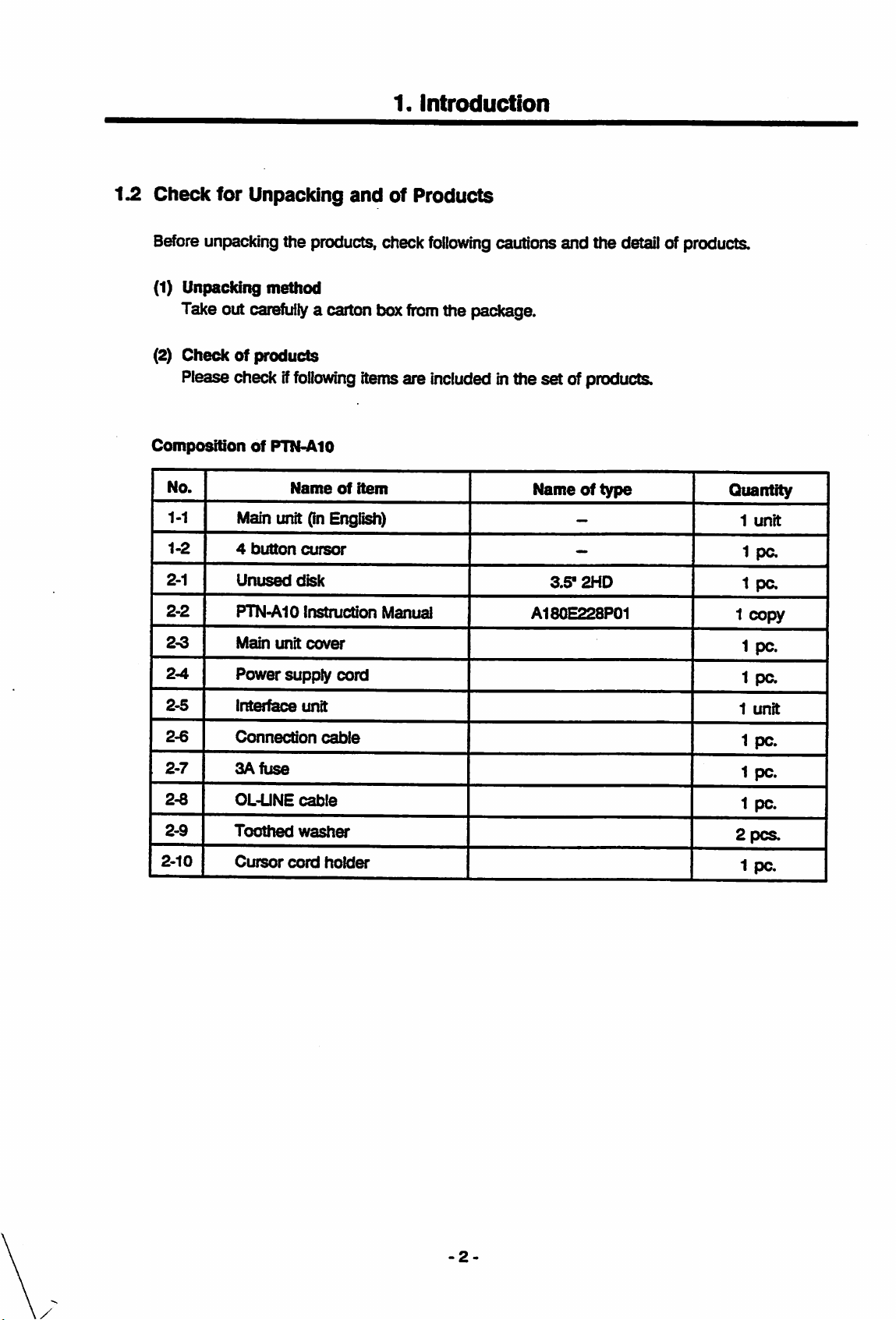
1.2
Check
for Unpacking
and
1.
Introduction
of
Products
Before
unpackingthe products, check
(1) Unpacking method
Take out
(2)
Checkofproducts
Please check if
carefully
foilowing
a carton box
CompositionofPTN-AIO
No.
1-1
1-2
2-1
2-2
2-3
2-4
Main unit (In English)
4
Unused
PTN-AIO
Main
Power
button
unit
Name
cursor
disk
Instruction
cover
supply
foilowing
from
the package.
cautions and the detailof products.
itemsare includedInthe set ofproducts.
of
item
Manual
cord
Nameoftype
—
—
3.5-
2HD
A180E228P01
Quantity
1
unit
1
pa
1
pa
1
copy
1
pc.
1
pa
2-5
2-6
2-7
2-8
2-9
2-10
Interim
Connection
3A
fuse
OL-UNE
Toothed
Cursor
cord
unit
cable
cable
washer
holder
1
unit
1
pc.
1
pc.
1
pc.
2 PCS.
1
pc.
-2-
Page 10
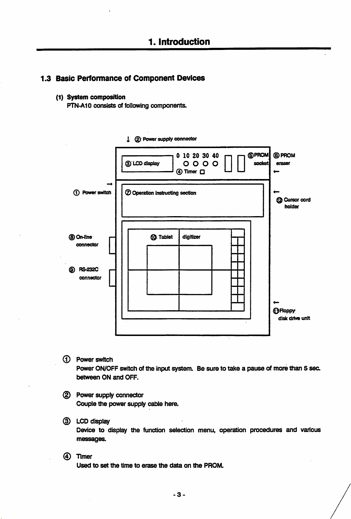
1.3
Basic
(1)
System
PTN-A10
1.
introduction
PerformanceofComponent
composition
consists
of fcllawing
X ®
Power
components.
supply
Devices
connector
0
Powerswiteh
(§)On-nne
connector
(§)
RS232C
connector
d);
LCD
®
Operatton
display
Instructing
©Tablet
010203040
O O O O socket
0
Timer
• LJ LJ
n n
section
digitizer
©PROM
eraser
©Cursorcord
holder
0Roppy
disk
drive
unit
©
Power
Power
between
(f)
Power
Couple
(D
LCD
Device to display
®
Timer
Usedtoset
switch
ON/OFF
ON
supply
the
display
switch of
and
OFF.
connector
power supply
the
the
timetoerase
the
input system. Be
cable
here.
suretotakeapause
function selection menu, operation
the
data
on
the
FROM.
3-
of more than 5
procedures
and
sec.
various
Page 11
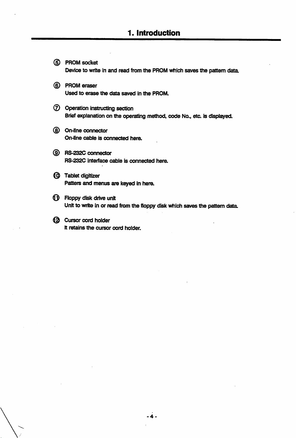
(f)
PROM
Device to write in
©
PROM
Usedtoerase
©
Operation
Brief
explanation on the operating method,
©
On-fine
On-fine
©
RS-232C
RS-232C
@
Tablet
Patters
socket
and
eraser
the
data
instructing
connector
cableisconnected
connector
interface
cableisconnected
digitizer
and
menus
are
1.
Introduction
read
fronn
savedinthe
section
hera
k^edinhera
the
PROM
PROM.
hera
which
code
saves
No.,
the
eta
is displayed.
pattern
data
O
Floppy
Unitto write in or read from
Cursor
It
retains
disk
cord
the
drive
holder
cursor
unit
cord
the
holder.
floppy disk which
saves
the
pattern
data
-4
Page 12
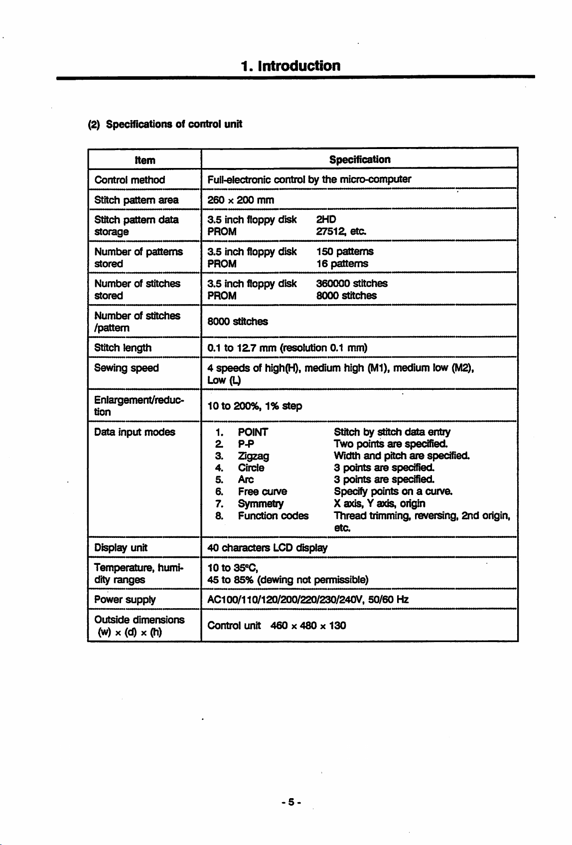
(2) Specifications of control unit
1.
Introduction
Item
Control
Stitch
Stitch
storage
method
pattem
pattem
area
data
Numberofpatterns
stored
Number
stored
Number
of
of
stitches
stitches
/pattern
Stitch length
Sewing
speed
Enlargement/reduc
tion
Data
input
modes
Specification
FuMectronlc
260X200
3.5
inch floppy
PROM
3.5
inch floppy
PROM
3.5
inch floppy disk
PROM
8000
stitches
control by
mm
disk
disk
the
micro-computer
2HD
27512,
150
16
360000
8000
etc.
patterns
patterns
stitches
stitches
0.1to12.7 mm (resolution 0.1 mm)
4
speeds
of high(H), medium high (Ml), medium low
Low (L)
10to200%,
1.
3.
4.
5.
6.
7.
8.
1%step
POINT
P-P
Zigzag
Circle
Arc
Free
curve
Stitchbystitch
Two points
Width
3
points
3 points
Specify pointsona cunre.
Symmetry X axis, Y axis, origin
Function
codes
Thread
etc.
data
entry
are
specified.
and
pitch
are
specified
are
specified
are
specified
trimming, reversing,
(M2),
2nd
origin.
Display unit
Temperature, humi
dity
ranges
Power
Outside
supply
dimensions
(w) XW X (h)
40
characters
LCD
dispiay
10to35«C,
45 to 85% (dewing not permissible)
AC100/110/120/200/220/230/240V,
Control
unit
460x480x130
50/60
Hz
Page 13
1.
Introduction
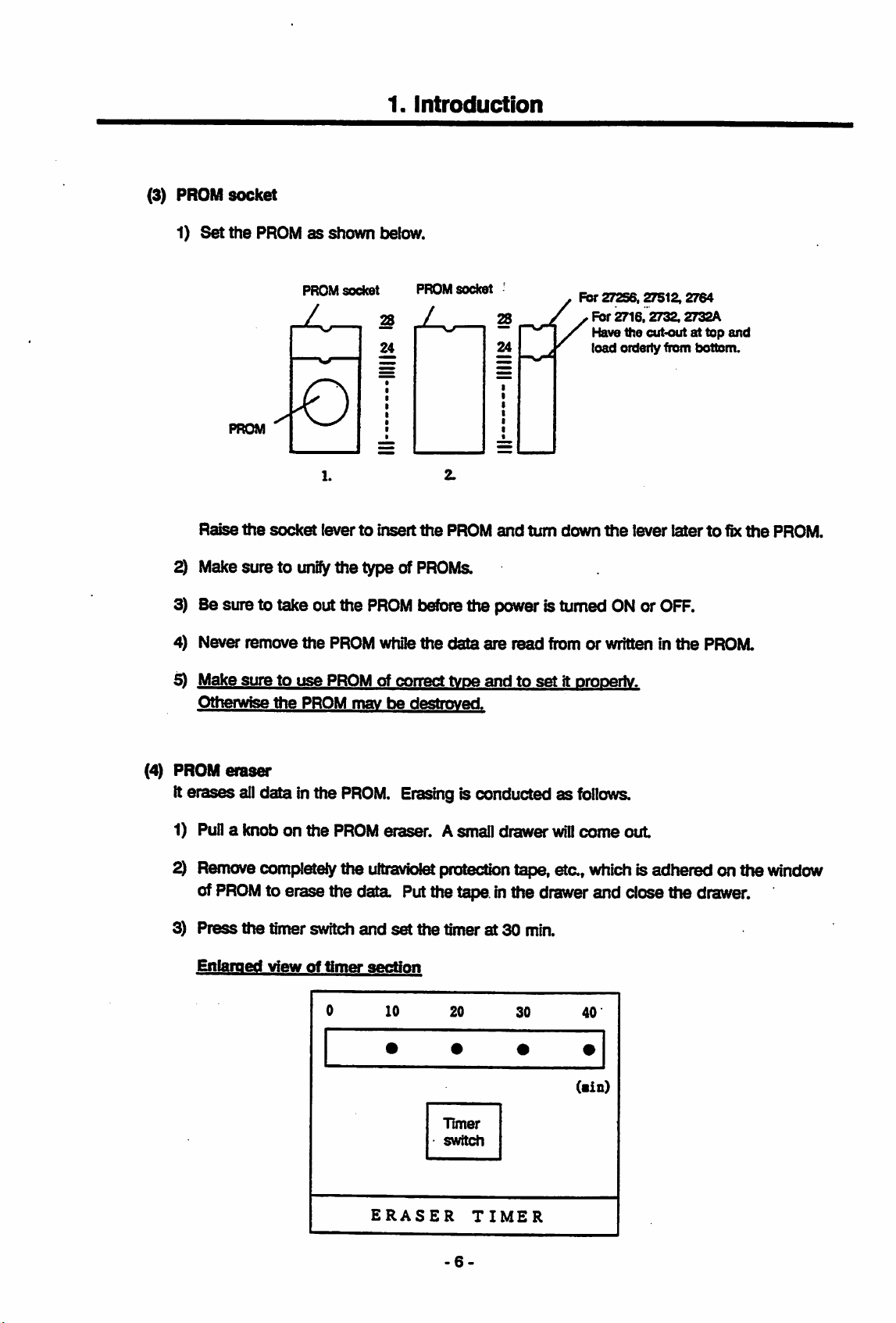
(3) PROM
1)
Set
Raise
socket
the
PROMasshown below.
PROM
the
socket
2) Makesure to
3) Be sure to take outthe
4) Never remove
PROM
socket
1.
levertoinsert
unify
the type of
the
PROM while
28
24
PROM
PROM
y
the
socket
PROM
28
24
and
turn
For
down
PROMs.
beforethe power is turned
the
data
are
read
fromorwritten In
27256,27512.2764
Fbr
2716,2732.2732A
Have
the
cut<outattop
load
orderlyfrom
the
lever
ONorOFF.
and
bottom.
latertofix
the
PROM.
the
PROM.
^ Make
(4) PROM
suretouse
Otherwise
eraser
Iterases alldata inthe
1) Pull a
2)
3)
knobonthe
Remove
of
PROM
Press
the
Enlarged
completely the ultraviol^ protection tape,
the
PROM
PROM
of correct tvoe
mavbedestroved.
PROM.
Erasingis conductedasfollows.
PROM eraser. Asmall
andtoset
drawer
it oropeilv.
will
come
eta,
whichis adhered on the
to erase the data. Putttie tape inthe drawer and
timer
switch
viewoftimer
and
section
set
the
timerat30
Timer
switch
min.
out
dose
window
the drawer.
ERASER
TIMER
-6-
Page 14
1.
Introduction
Erasing time
switch. Erasing time
system. Erasing
4) When the erasing did not
the
erasing
5) When the erasing is over, adhere
PROM.
r*'
will
change one after anotherasshown
40min.
time
takes
and
canbeset
place at
30
end
erase
any timesofarasthe
the
set
erasing
min.
within
30 min., clean
again.
the
ultraviolet protection tape,
20
min.
(5) Tablet digitizer
Tablet digitizer consists of the tablet and cursor (mouse).
1) Tablet
Menu section is provided at right
end.
Pattern
t>elow
with
power is supplied to
time.
10
min.
the
erasingwindow of
data
canbeinputatany
each
push on
0
min.
etatothe
—1
PROM,
window of
other
the
the
extend
area
timer
input
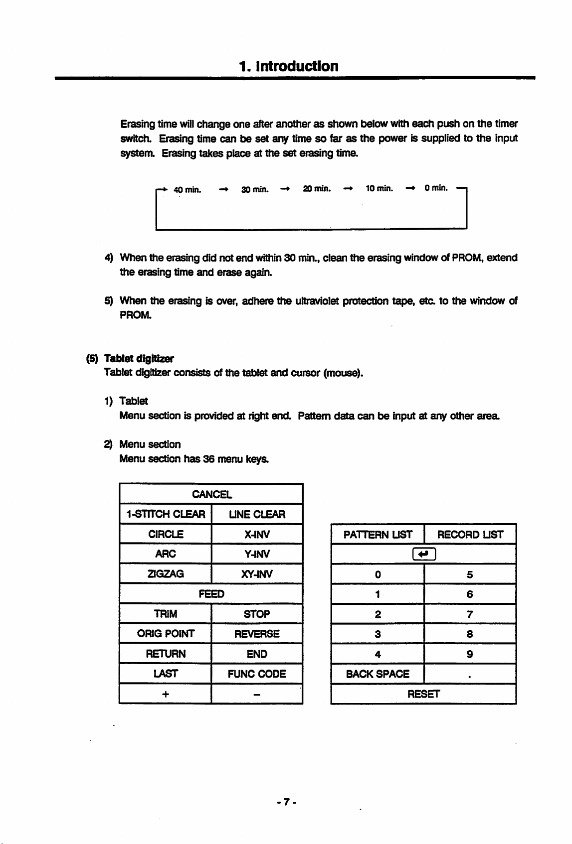
2) Menu section
Menu section
l-STITCH
CIRCLE
ARC
ZIGZAG
TRIM
ORIG
POINT
RETURN
LAST
+
has36menu keys.
CANCEL
CLEAR
FEED
UNE
REVERSE
FUNC
CLEAR
X-INV
Y-INV
XY-INV
STOP
END
CODE
-
PATTERN
0 5
1 6
2
3
4 9
BACKSPACE
UST
RESET
RECORD
7
8
UST
.
-7
Page 15
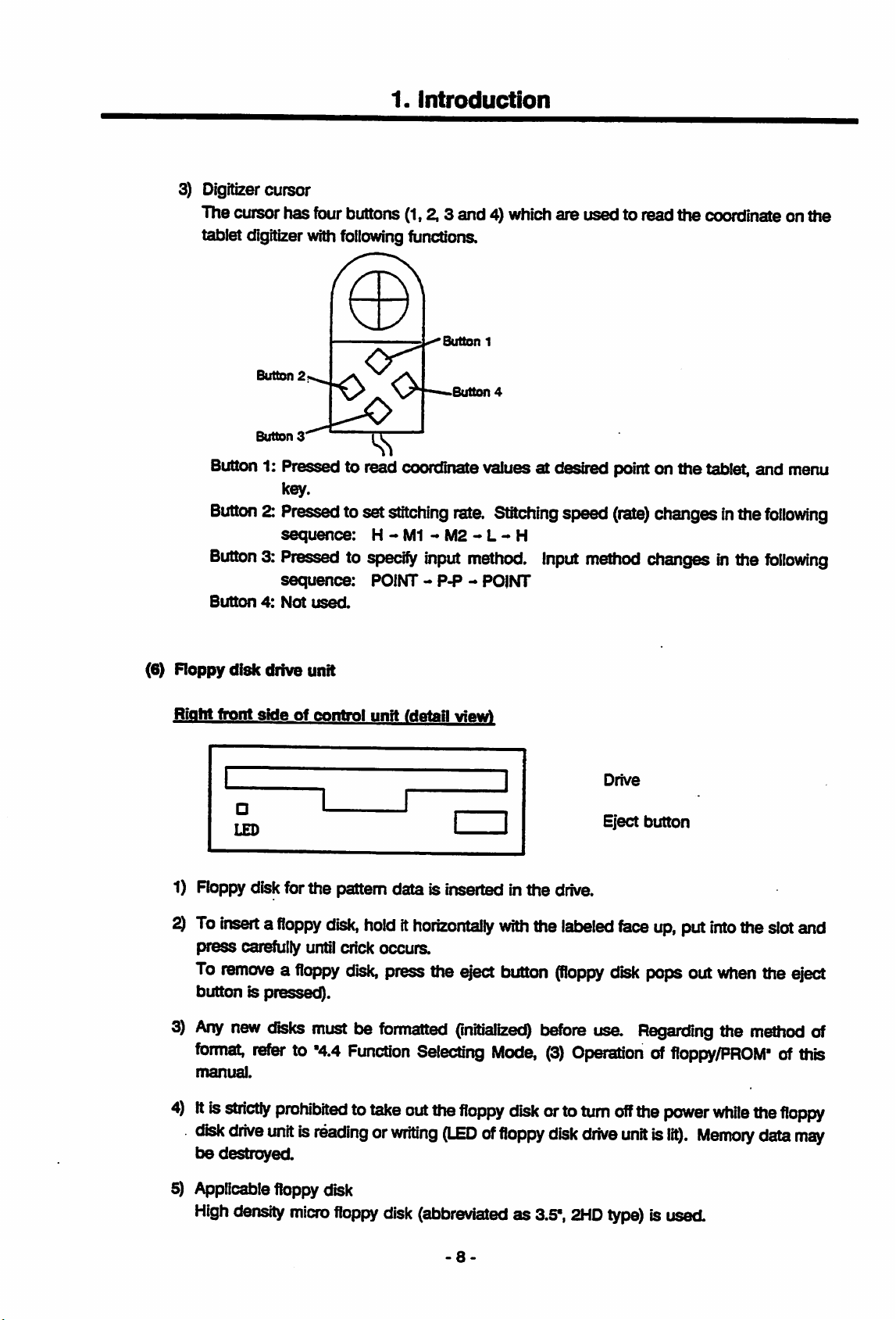
3) Digitizer cursor
The cufsor has fourbuttons
tablet digitizerwith
Button
Button
following
2
3
1.
Introduction
(1,2.3
functions.
Button
Button
and4}whichare used to read thecoordinate on the
1
4
Button
Button2:Pressed
Button3:Pressedtospecify
Button4:Not
(6)
Roppy
Right
1) Roppy diskforthe pattern data is inserted inthe
1: Pressed to read coordinate values at desired pointon thetablet, and menu
key.
toset
disk
front
sideofcontrol
sequence:
sequence:
used.
drive unit
stitching
H-M1
POINT -
unit
fdctail
rate.
-M2-L-H
input
method.
P-P-POINT
viewA
Stitching
Input
speed
drive.
(rate)
method
Drive
Eject
changesinthe
changesinthe
button
following
following
^
To
insertafloppy
press
carefully until crick occurs.
To
removeafloppy
button is pressed).
3)
Any
new
disks
format,
manual.
4)Itis
disk
be
5) Applicable
High
referto"4.4
stn'cUy
drive
unitisreadingorwriting
destroyed.
density
prohibitedtotake
floppy
disk,
holdithorizontally
disk,
press
mustbeformatted
Function
disk
micro
floppy
disk
with
the
eyect
button
(initialized)
Selecting
out
the
Mode,
floppy
disk
(LEDoffloppy
(abbreviatedas3.5",
-8
the
labeled
(floppy
before
(3)
orto
disk
face
up,
put
into
the
slot
and
disk
pops
out
when
the
eject
use.
Regarding
the
method
Operationoffloppy/PROM"ofthis
turn
off
the
drive
2HD
unitislit).
type)
isused.
power
while
the
Memory
data
floppy
may
of
Page 16
1.4
Cautions
(1)
Safety
Switch
great
(2) Environment
1)
2) Do not expose the system to the direct sunlight or do not place it
3) Care should be taken to prevent
4)
5) Itis prohibited to apply any strong impact to
for
Operation
off
the
power
dangerofelectric
Do
notoperatethe
or
lower
temperature
likearoom
metal particles into
^stem
or
oil
intense
heater.
cannot be operated inthe atmospherecontaining the
met
vibrations.
1.
t>6fore
access to the
shockifyou
system
(ICTC
the
control device or
introduction
insideofunit
touch
the
charging
underthe
or under). Otherwise, the
environmentofhigher
the
intrusionof water,
the
tablet digitizer.
the
system or to operate itwhere there are
for
inspectionorrepair.
section
while
the
temperature
matfunction
dose
liquid
or etectridty conducting
explosive
(There
powerissupplied.)
(35°Corover)
or falure occurs.
to a heat source
gas, dense dust
is a
(3)
Power
1) Operate the system
2) When there isaninstantaneous powerfailure,
(4)
Noises
1) Ifa
2)
3) Noises mayberaised if a radio or TV is
supply
rating.
error
Insuch occasion, turn off
surge
disturbed
Same
raises large noises. Be
(Example: High frequency welder, etc.)
power
voltage
with
the power supply which is
state
and
stopstooperate.
the
power
voltage (noise) is appliedtotfie power supply line,
temporarily.
problem may be encountered if
suretosecure
supply
for
themoruse
themata
within
the
system is broughttothe reset or
and
tsack on again to resume
the
system is operated near any device which
a sufficient distance from
used
remote
around
place.
the
the range of ± 10% of the
the
operation.
the
system control may
such
device.
system. Provide a
separate
the
be
9-
Page 17
2.
Before
2.1
Basic
(1)
Roppydisk
1)
Starting
Knowledge
Floppy
utilizes
magnetism.
disk
the magnetism and its
2. Before Starting
the
Operation
should
be
handled
memory
carefully
the
Operation
because it is a
couldbe destroyedunder the effectof a strong
precision
component
which
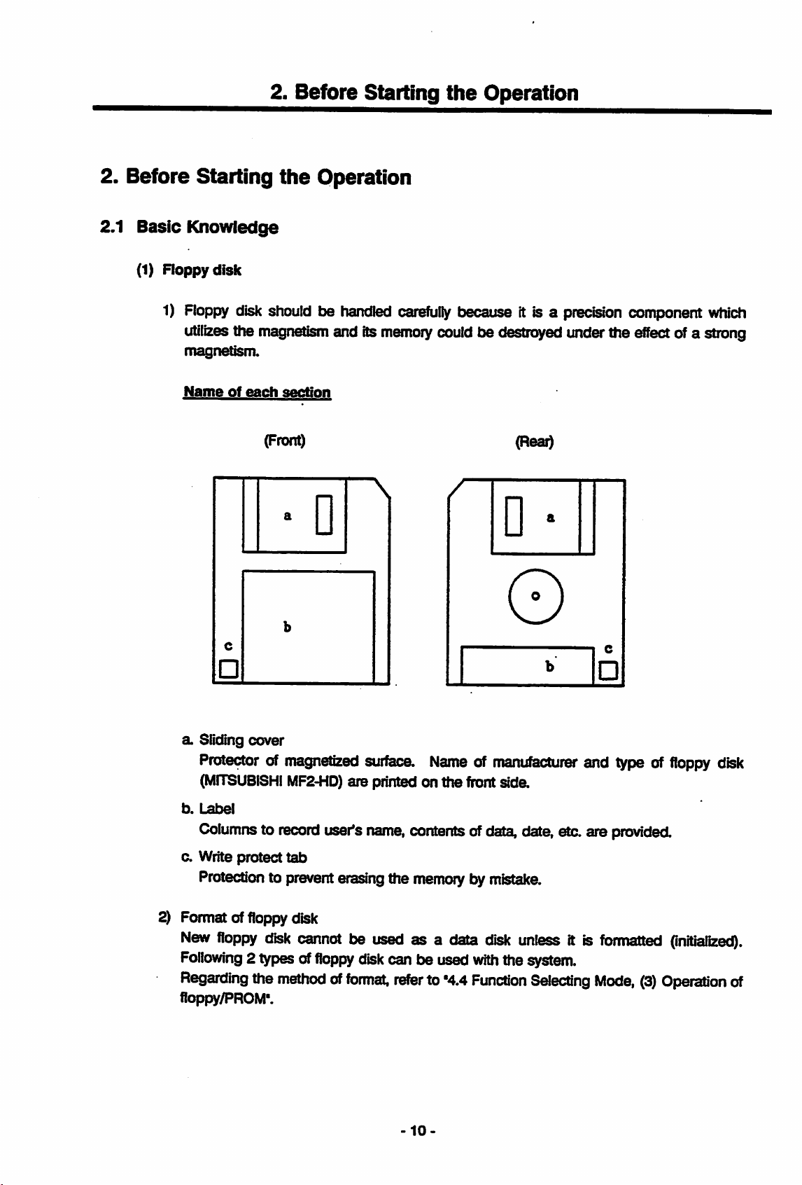
Name
a. Sliding cover
of
each
section
(Front)
Protectorofmagnetized
(MITSUBISHI
MF2-HD)
D n
surf^.
are printed on the front
Nameofmanufacturer
sida
(Rear)
and type of
floppy
disk
b.
Label
Columnstorecord
a Write protect
Protection to preventerasingthe
2) Format of
New
Following
Regarding
floppy/PROM'.
floppy
floppy
2 types of
disk
the
methodofformat,
tab
disk
cannot
user's
name,
be used as a data
floppy
disk
can be used
refer
-10-
contentsofdata,
memorybymistake.
disk
with
the system.
to'4.4
Function
data
etc. are
unless
Selecting
it is
provided.
formatted
Mode,
(3)
(initialized).
Operation
of
Page 18
2.
Before
Starting
the
Operation
TypeoffloDDv
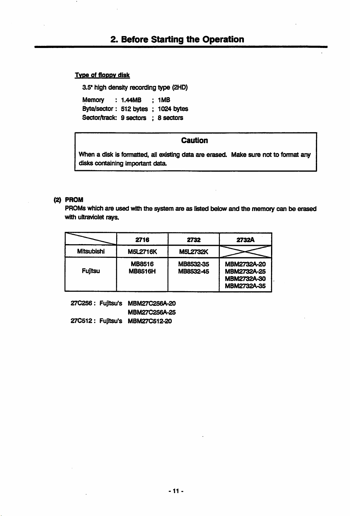
(2) PROM
PROMs
with ultraviolet
Mitsubishi
disk
3.5*
high density recording type
Memoiy : 1.44MB ; 1MB
Byte/sector:
Sector/track: 9
512bytes;1024bytes
sectors
; 8
When a disk is formatted, ail existing
disks containing important
data
(2HD)
sectors
Caution
data
are
erased.
Make
sure
nottoformat
whichare used withthe system are as listed below and the memory can
rsys.
2716
M5L2716K
2732
M5L2732K
2732A
any
be
Fujitsu
27C256:
27C512:
MB8516
MB8516H
Fujitsu's MBM27C256A-20
MBM27C256A-25
Fujitsu's MBM27C512-20
MB85^-35
MB8532-45
MBM2732A-20
MBM2732A-25
MBM2732A-30
MBM2732A-35
11
Page 19
22
Operating
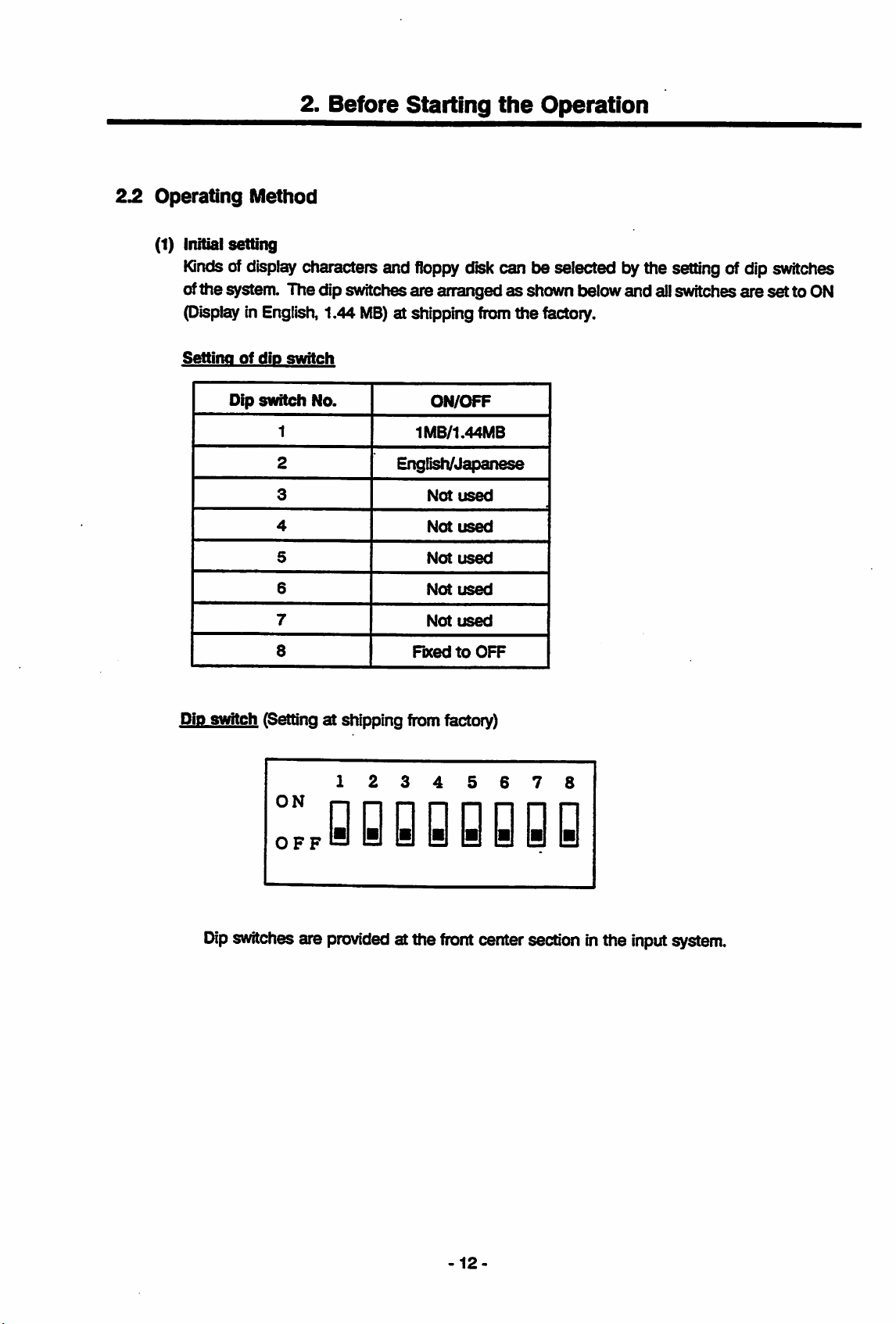
(1) Initial setting
Kindsofdisplay
ofthe system. The dip switches are arrangedasshown below and allswitches are
P'isplay in English, 1.44
2.
Method
characters and
Before
MB)
Starting
floppy
the
Operation
diskcan be selected by the settingof dip switches
at shipping fromthe factory.
set
to ON
Setting
Dip
of
dip
switch
switch
1
2
3
4
5
6
7
8
No.
ON/OFF
1MB/1.44MB
English/Japanese
Not
used
Not
used
Not
used
Not
used
Not
used
FixedtoOFF
Dip switch (Setting at shipping from factory)
Dip
switches are
OFF
yyyyyyyB
provided
at the
front
centersectionin the inputsystem.
12
Page 20
2.
Before
Starting
the
Operation
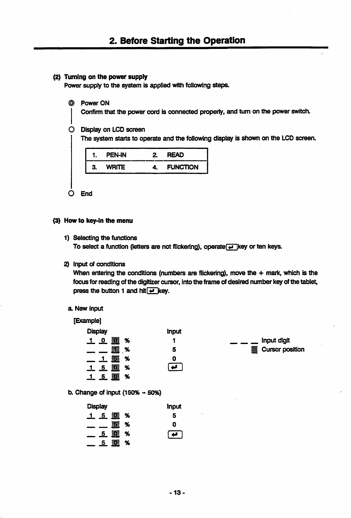
(2) Turningonthe
Power supply to
©
Power
ON
Confirmthat
O Displayon
The system startsto operate
1.
3.
O
End
(3) Howtokey-in
1) Selecting
select
To
the
a function (letters
power
supply
the
system is appHed with following
the
power cord is connected properly,
LCD
screen
and
PEN-IN
WRITE
the
menu
functions
2.
4.
are
READ
FUNCTION
not
flickering),
steps.
and
turn on
the
following display is shown on
operater^key
or
the
power switch.
the
ten
keys.
LCD
screen.
2) Input of conditions
When enten'ng
focusfor reading of
press
the
a New input
[Example]
Display Input
J_
the
button1and
^ M * 1
® % 5 ^
tx
Change
of input (150% 50%)
Display
-L
^
li
M % 0
conditions (numt>ers
the
digitizer cursor, into
hitM
kev.
0
% S
%
Input
% 5
are
flickering), move
the
frameof
desired
the
+ mark, which is
number
key of
Inputdigit
Cursor
the
tabl^
position
the
5.
H %
-13-
Page 21
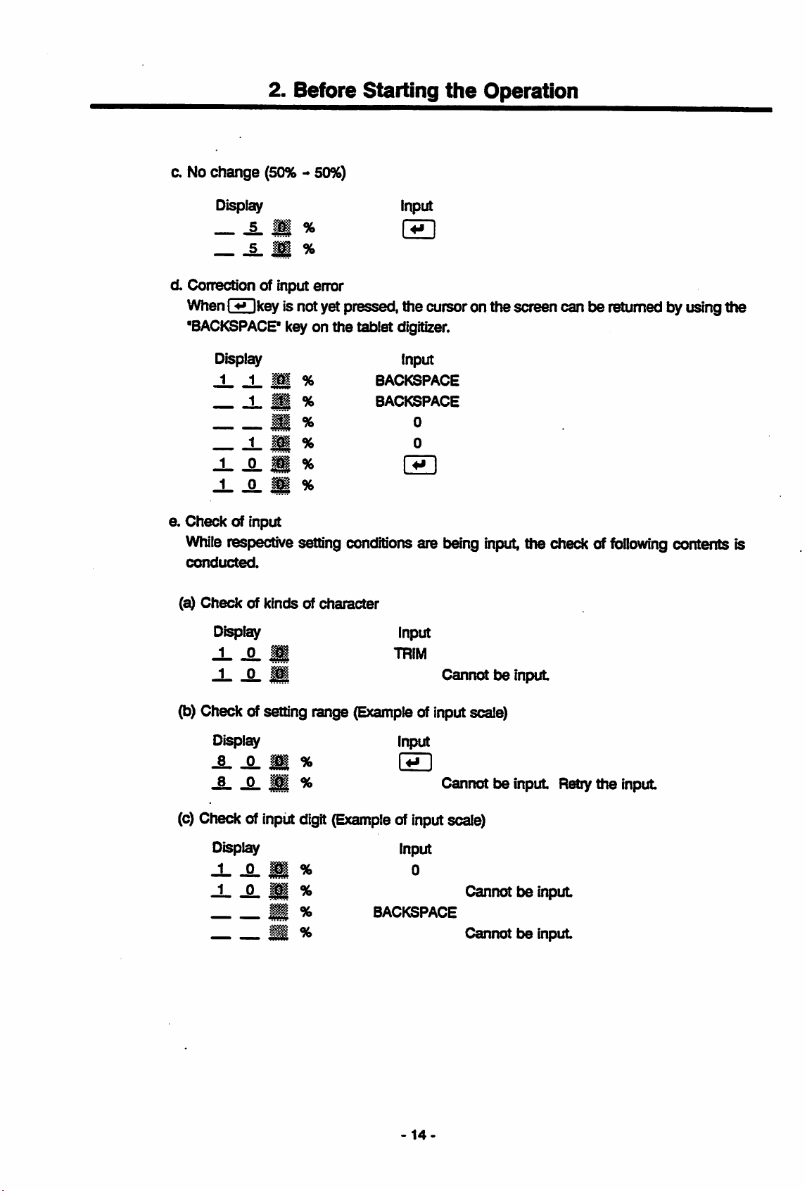
c. No
2. Before
change
Display input
(50% 50%)
Starting
§. s % ®
i.
%
the
Operation
d. Correction of input
When\4*ikev
"BACKSPACP key on the tablet digitizer.
Display
1 1 1m %
1.
1
1
1 i
J-
-Q. 1
J-
J2-
i
e.
Check
While
conducted.
(a)
of input
respective setting
Check
of kinds of character
Display Input
J-
-0. S
J
Q.
^
ener
isnotyet pressed, the cursoron the screen can
BACKSPACE
^ %
BACKSPACE
M %
M %
'& %
M %
conditions
TRIM
Input
0
0
are
being
Cannot
input,
tse
input
t>e
the checkof
returnedby usingttie
following
contents is
(b)Check ofsetting range
Display Input
-8.
^ ®
JL
^ S ^
(c)
Checkofinput
Display Input
-L
A M * 0
digit
(Exampleofinput
J ^ X %
® %
S % Cannot
(Example
ofinputscale)
BACKSPACE
Cannotbeinput
scale)
Cannotbeinput
t}e
Retiy
input
theinput
-14-
Page 22
2.
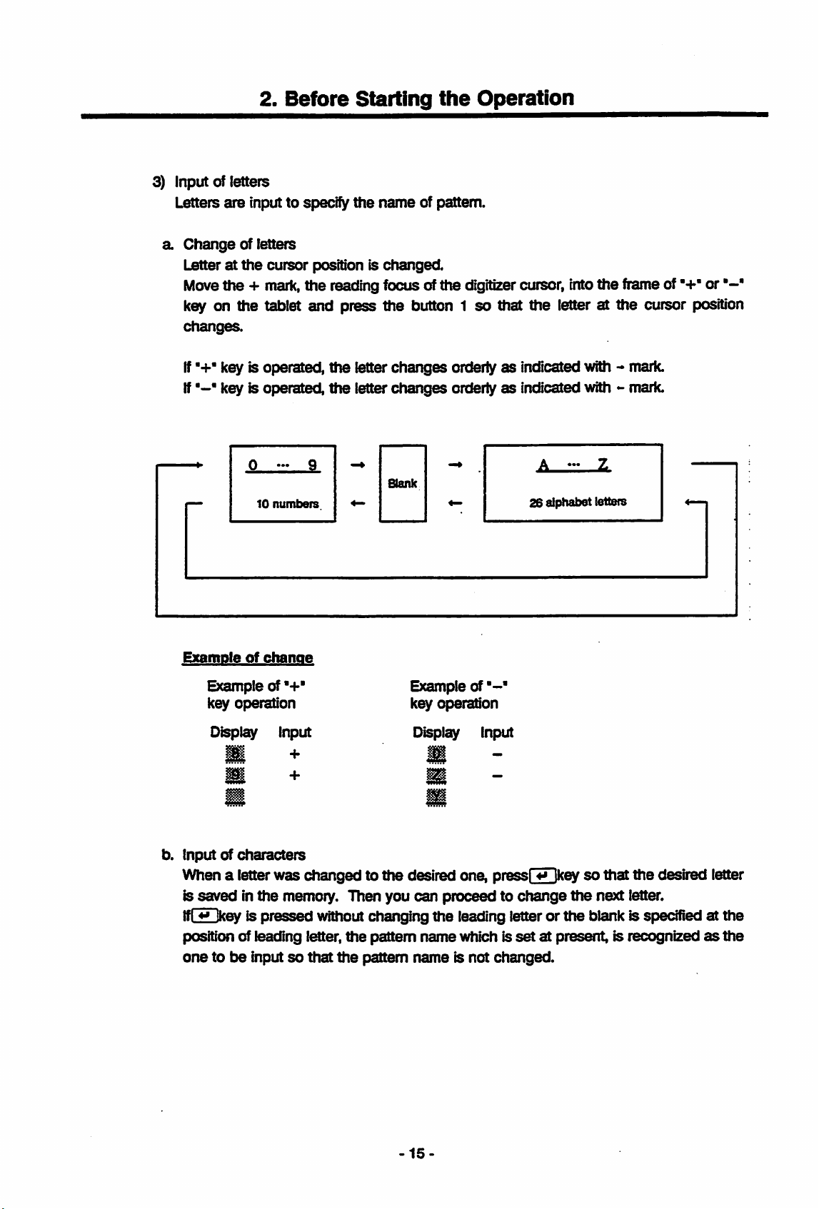
3) Input of letters
Letters
a
are
input to specify
Change
Letteratthe
Move
of letters
the +
Before
cursor
mark,
position is
the reading focus ofthe digitizer cursor, intotheframe of
Starting
the
name
changed.
key on the tablet and press the button 1
changes.
the
of pattern.
Operation
•+"
so
that the letter at the cursor position
or
If'+* key is operated,
If key is operated,
10
numbers
Example
of
ctMrnoe
Example of
key
operation
Display Input
•+•
the
the
letter
letter
changes
changes
Blank
orderlyasindicated with mark.
orderlyasindicated with mark.
Example of
key operation
Display Input
26 alphabet letters
b. Input of
When a letter
is
IfLilJkey is
position of leading letter,
onetobe
characters
savedinthe
pressed
inputsothat
was
changedtothe
memory. Then you
without changing
the
pattern
the
pattem
desired one, press! Ikeysothat
can
-15
the
name
name
proceed to
leading letter or
which is
is not
change
setatpresent, is recognizedasthe
changed.
the
the
next letter.
the
blank is specified at
desired letter
the
Page 23
2. Before
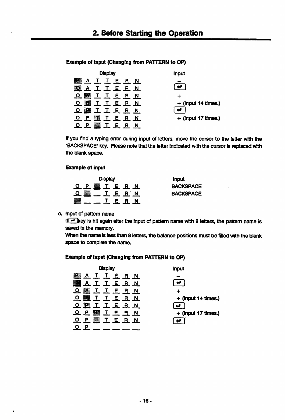
Example of Input (Changing from PATTERNtoOP)
Display Input
Starting
the
Operation
•-L-L-S-JL
+
-S-
S
-I- -I-
-Q-B
X
-Q- -E- S X X -B-
O P ^ T E R N
-S- -B-
JL-i--R.
-M-
+
JL I^D
JL
+
(Input
(Input
14times.)
17times.)
Ifyou find a typing error during input of letters, move
'BACKSPACP
the
blank
Exampleofinput
-Q- X B X X -B-
-O. • _ X X X
•
c. Input of
Ifl**Ikev
savedinthe
When
the
spacetocomplete
Example of input (Changing from
k^.
Pleasenote that the letter indicated withthe cursoris replaced with
space.
Display Input
JL
JL
TERN
pattem
is hitagain afterthe inputof pattem name
name
memory.
name is lessthan 8 letters,
the
name.
Display Input
the
balance positions mustbefiiled
PATTERN
BXXXXXX
S
J-J.
^-B.
JL
X S X X X X X +
X®XXXXX
X X B X X X X +
XX
^ P
X X X X
the
BACKSPACE
BACKSPACE
with
8 letters,the pattem name is
to OP)
CH]
+
(Input14times.)
(Input
17times.)
cursor to
the
with
letter with
the
blank
the
16-
Page 24
2.
Before
Starting
the
Operation
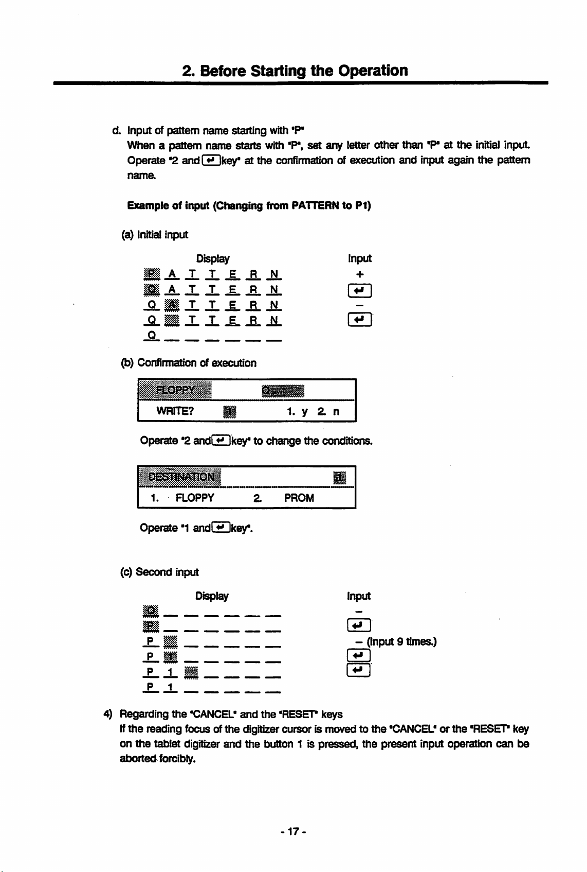
d. Input of pattern
When a pattern name starts with 'P*.
Operate*2andi^key*
nama
Exampleofinput (Changing from
(a)
Initial
input
M A T T E R N
M A T T E R N
JSL
M X
Q T T E R N
.0
(b) Confirmation of execution
WRITE?
name
Display
JL
starting with
at the
-i-
-E- -N
P
1 1. y 2. n
'P'
set
any letter other than
confirmation
PATTERNtoPI)
"P"atthe
initial
input
of execution and inputagain the isattem
Input
Operate '2 andC^key*to changethe
1.
Operate '1 andLUJkey'.
(c)
Second
aZZZZZZ
P U -
i_L«
P 1
4) Regarding
If
the
reading focus of
on
the
tablet digitizer
aborted
forcibly.
FLOPPY
input
Display Input
the
"CANCEL"
Z
and
the
digitizer cursor is moved to
and
the
PROM
the
"RESET"
button 1 is
conditions.
m
E
®
E
keys
pressed,
(Input9times.)
the
"CANCEL"orthe
the
present
"RESET key
input operation
can
be
17-
Page 25
2. Before
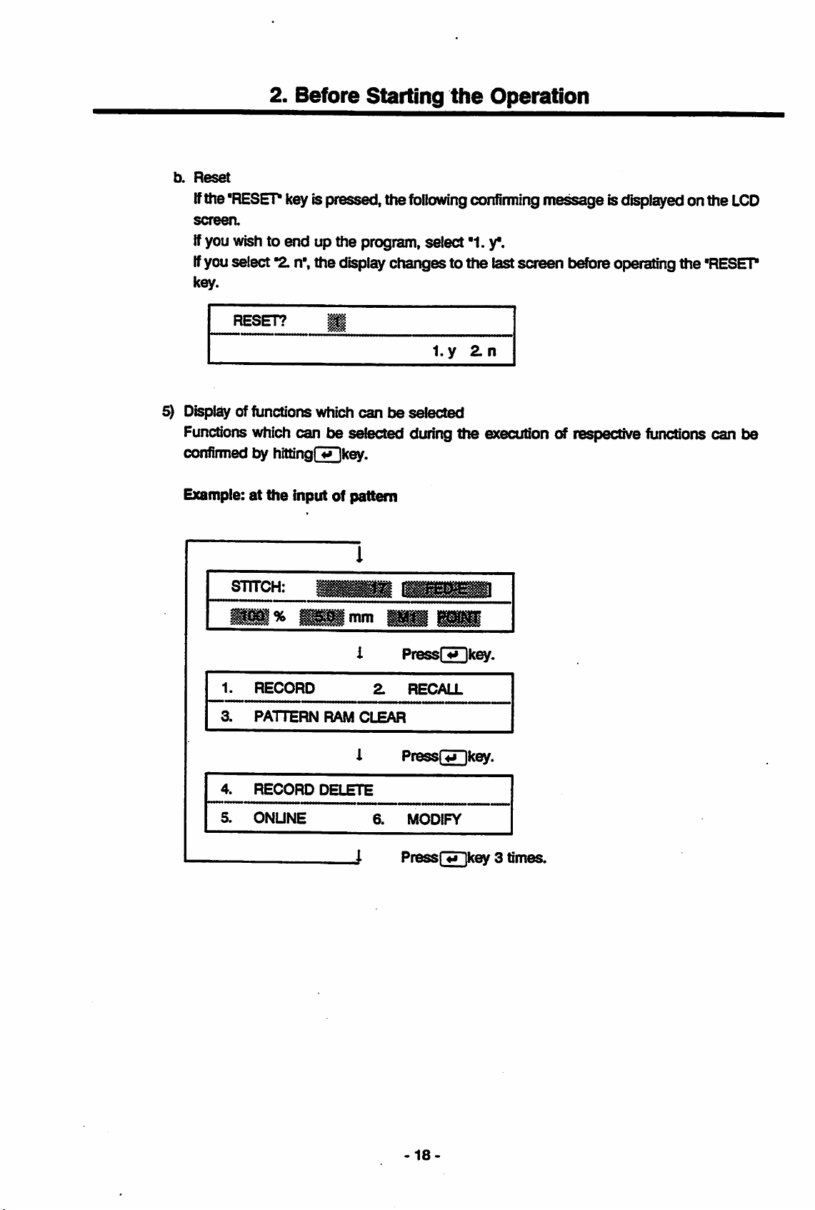
b.
Reset
ifthe'RESEP keyispressed, the
screen.
If
you
wish
to end up the program, select
If
youselect
key.
"2.
n', the display changes to the lastscreen
Starting
fbllowirtg
the
Operation
corrfirming
"1.
y*.
me^ge
tsefore
isdisplayedonthe
LCD
operating the 'RESET
RESET?
1
5) Displayof functions which
Functions
confirmed by
Example:atthe
STITCH:
1.
3.
which
can be selected duringthe execution of respective functions can be
hittinqr^kev.
input of pattern
%
RECORD
PATTERN
RAM
l.y
canbeselected
mm
Press!
Z
RECALL
CLEAR
4*
Zn
ikev.
4.
5.
RECORD
ONUNE
DELETE
PressHSHkey.
6.
MODIFY
Press
-18
fTTikey3times.
Page 26
2.
Before
Starting
the
Operation
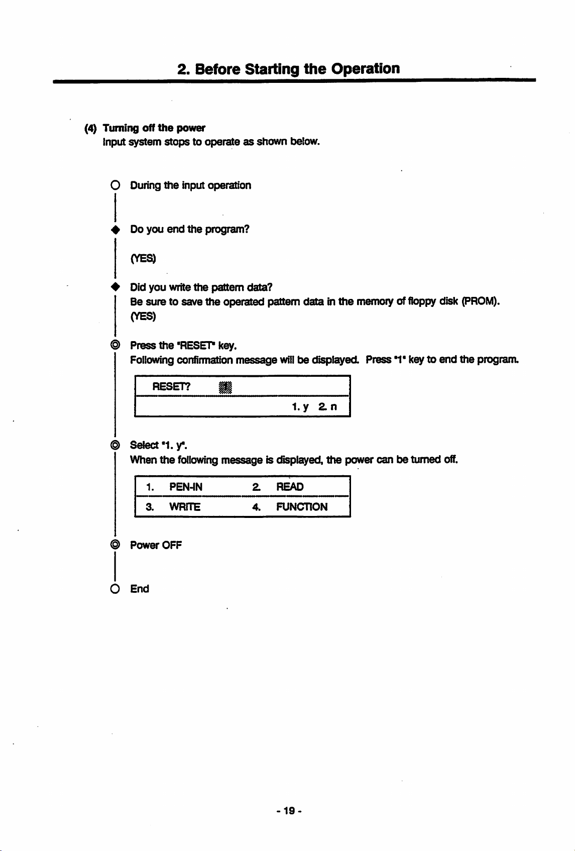
(4) Turning off
Input
system
the
power
stopstooperateasshown
O Duringthe input operation
4 Do
you
(YE^
end
the
# Didyou write
Be sure to save the operated pattern data in
(YES)
® Press the 'RESET
Followingconfimriatlon
RESET?
program?
the
pattern data?
key.
message
t}e!ow.
the
willbedisplayed.
1. y
2.
n
memoryof
floppy
Press1*key to
disk
end
(PROM).
the
program.
Select
When
Power
O
End
*1.
y.
the
following
1.
PEN-IN
3.
WRITE
OFF
message is displayed,
2.
READ
4.
FUNCTION
the
power can be turned
off.
-19.
Page 27
2.
Before Starting
the
Operation
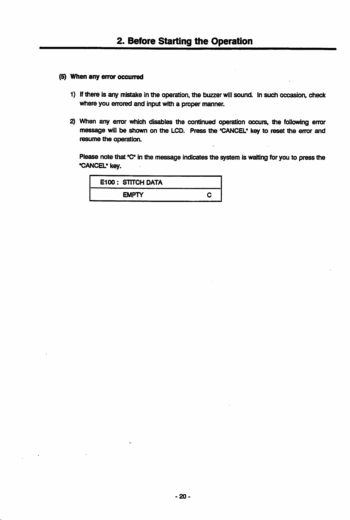
(5) When
any
error
occuired
1)Ifthere is any mistake inthe operation,the buzzer
where you errored
2) When any error
message
resume
will
the
operation.
Please note that
•CANCEL'
key.
E100:
and
input with a proper manner.
which
t>e
shownonthe
'C
inthe message indicates the system is
STTTCHDATA
EMPTY
disables the continued operation occurs, the
LCD.
Press
win
sound. Insuch occasion, check
the
"CANCEL' keytoreset
waiting
following
the
error
error
and
foryou to pressthe
-20
Page 28
3.
Basic
input
3.
Basic
Input
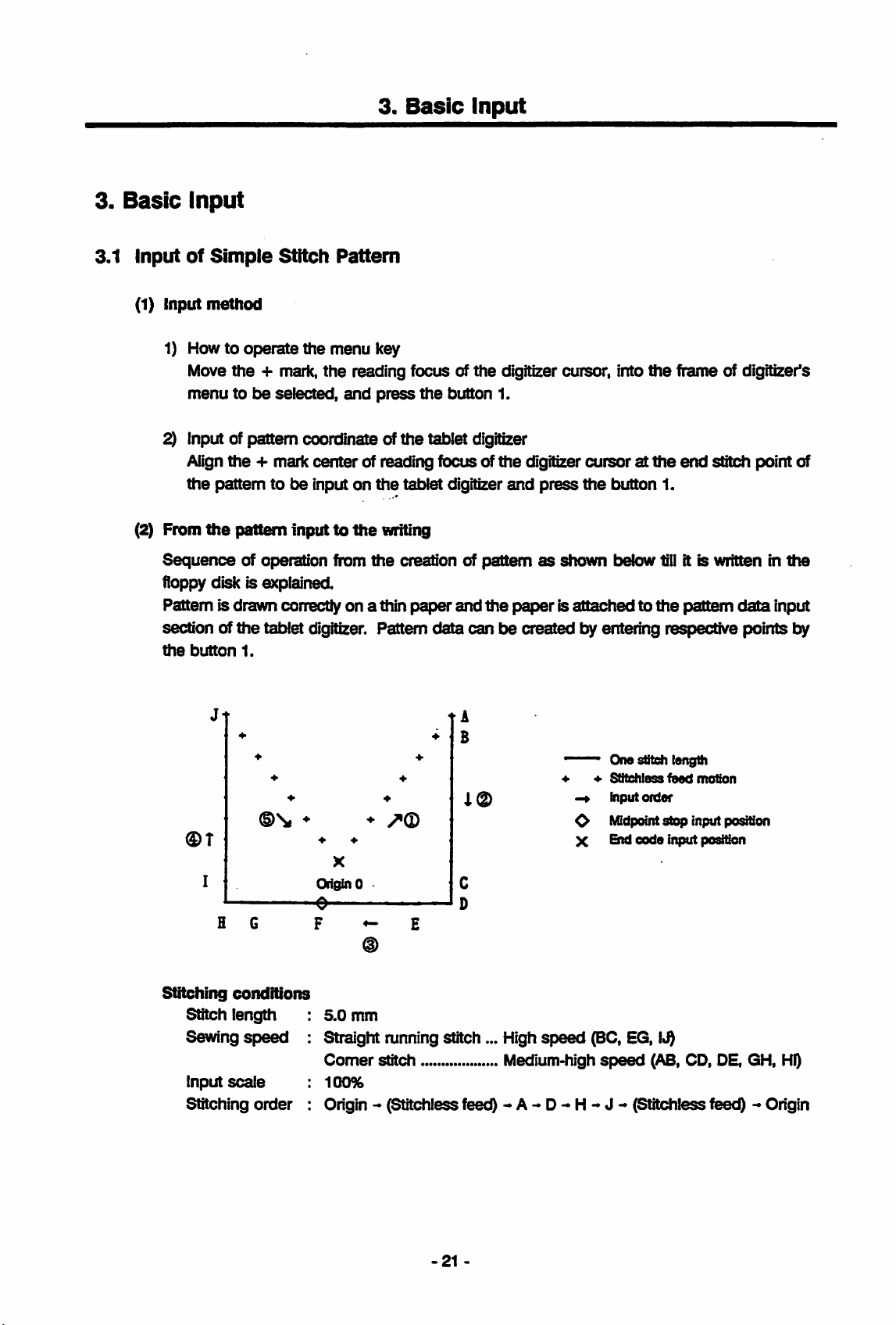
3.1 InputofSimple
(1) Input
(2) From
method
1) Howtooperate
Move
the
menutobe
2) Input of pattem coordinate of
Align
the
+ mark
the
pattemtobe
the
pattem
Sequence
of operation from
floppy disk is explained.
Pattem is drawn correctly
section of
the
button
the
1.
Stitch
+ mark,
selected,
the
Pattern
menu
key
the
reading focus of
and
press
the
center
inputonthe
Inputtothe
of reading focus of
tatjiet digitizer
writing
the
creation of
on
a thin
paper
tablet digitizer. Pattem
the
the
button
1.
tablet digitizer
the
pattemasshown
and
the
data
canbecreated
digitizer cursor, into
digitizer
and
press
cursoratthe
the
button 1.
below till it is written in
paperisattachedtothe
lay
entering respective points
the
frame of digitizer's
end
stitch point of
pattem
data
the
input
t>y
Jt
0r
I
Stitching
Stitch length
Sewing
Input
Stitching
©Si
H G
conditions
speed
scale
order
t A
B
i©
♦
♦
OriginO
0
F ^ E
:
5.0
♦
^(D
♦
X
mm
: Straight running stitch... High
Comer
:
100%
: Origin - (Stitehlessfeed) -
stitch Medium-high
A-
speed
D-
One Stitch length
Stitehless
input
Midpcrint
O
End
X
(BC, EG,
speed
H-
J-
feed
motion
order
stop
input position
code
input position
i«0
(AB,
CD, DE, GH,
HQ
(Stitehlessfeet^ -»Origin
-21
Page 29
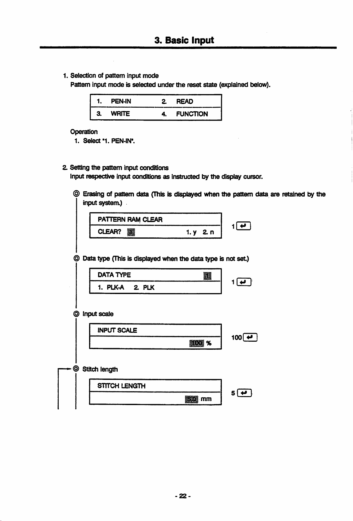
1. Selection of pattern input mode
Pattern input
Operation
1.
Select
modeisselected
1.
PEN-IN
3.
WRITE
"1.
PEN-IN'.
3.
under
2.
4.
Basic
the
READ
FUNCTION
input
reset
state
(explained tselow).
2. Setting
the
pattern input conditions
Input respective input conditions
®
Erasingofpattern
input system.)
PATTERN
CLEAR?
@ Datatype
DATATYPE
1.
PLK^
(This
data
RAM
g
1
is displayed whenthe data type is not
2.
® input scale
INPUT
SCALE
as
instructed
(Thisisdisplayed
CLEAR
PLK
l.y
t>y
the
when
2.n
display cursor.
the
p)attem
data are
set)
100
retained
bythe
—Stitch
length
STITCH
LENGTH
mm
-22-
sS
Page 30
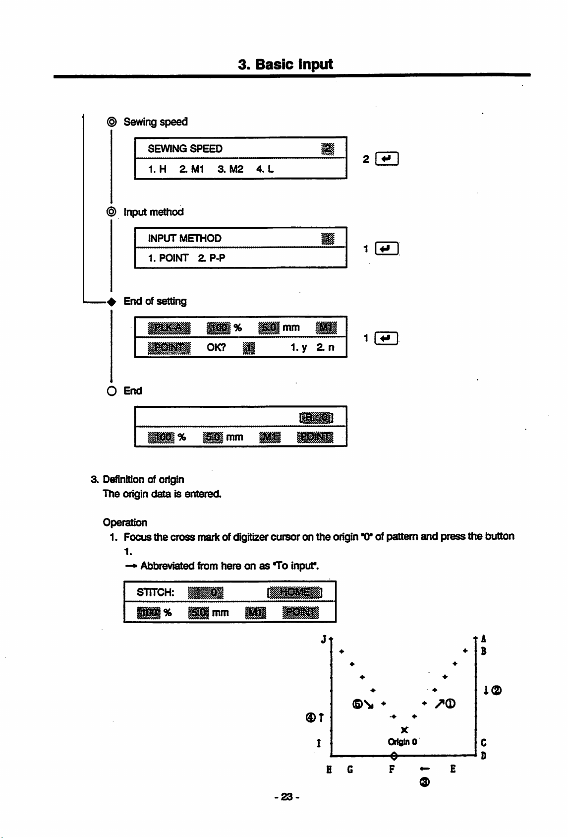
© Sewing speed
3.
Basic
input
SEWING
1.
H
© Input method
INPUT
1.
POINT
End
of setting
O
End
SPEED
Zm
METHOD
ZP-P
pii%
OK?
3.
2 [HD
M2
4.
L
1
mm
l.y
\
i
2.n
1CZ3
3.
D^nition
The
Operation
1. Focus
of origin
origin
data
is entered.
the
cross
1.
—•
Abbreviated from
STTTCH:
%
%
HH
mm
markof digitizercursoron
hereonas
illimm
To
-23-
inpur.
©T
the
Jt
I
origin
B G
*0*
®\i
of pattern
♦
X
OrklinO
0
*
and
♦
O
press
E
the
t A
button
B
i(2>
Page 31
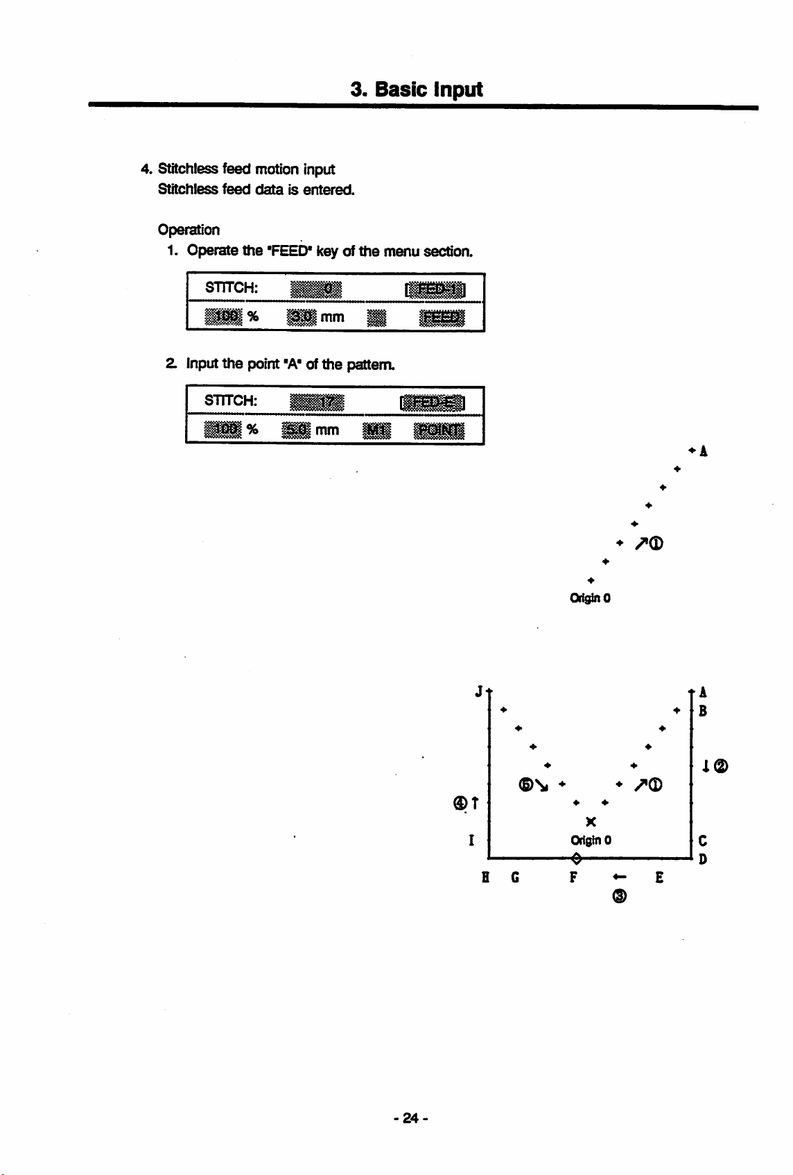
4. Stitchless feed motion input
Stitchless
feed
dataisentered.
Operation
1. Operate
the
'FEED*
key of
3.
Basic
the
menu section.
Input
STTTCH:
•1%
2. Input
STITCH:
Hi
the
point
"A"ofthe
% H
••
1
pattern.
mm
1
•">"
Ml
HH
♦A
♦
♦
Ori^O
0T
Jt
I
H G
<5)\
♦
♦
Origin0
0
F E
♦
♦
X
tA
B
i(2)
24-
Page 32

5. Point input
One-sdtch
Operation
1. Input
dataisentered.
the
point'B'of
the
3.
Basic
pattern.
Input
snrcH:
SB
SHl
V
♦
IB
Ol^O;
Jt
(S>\
♦ ♦
X
I
Origin 0
^(D
ti
B
i(2)
H G
-25
F E
Page 33

3.
Basic
input
6. Change of sewing
Sewing
Operation
1. Press
speed is changed
the
button of digitizercursor 2 or 3 times.
Eachpress onthe button 2 change the speedstep bystep,
- Lxw - High -
STITGH:
STITCH:
STITCH:
1%
speed
Medium
|
••
®
•
^ M
mm
1
^^nim
from
high
medium
—.
m
highspeed
BB
enBi
IHH
mmmm
(Ml)
to highspeed
Medium
(H).
high-
Medium
low
7. Input method change
Input
mode is changed
Operation
from
point
1. Press the button3 of digitizer cursor.
With
each
press
onthe
line-—.
snrcH:
%
button
mm
(POINT)
to straight line
3, itchanges
from
Point-Straight
Jt
®T
I
AG
(P-P).
One-Point-Straight
tA
B
♦ ♦
X
Origin 0
e
F E
(3>
26
Page 34

8. Straight line (P-P)data input
Straight line (P-P) is entered.
Operation
1. Input
the
point'Cofthe
3.
Basic
pattern.
input
snrcH:
\%
1
SI
t A
B
/>0
Oi^O
t A
B
X<2>
®T
Jt
I
E G
♦
♦
(§>S<
♦ ♦
X
O^inO
-e
F E
-27-
Page 35

3.
Basic
Input
9. Bend
Sewing
(POINT)
Operation
1. Press
2.
data
input
spe^ischangedtomedium
and
bend
dataisinput
the
button 2 of mouse (digitizer cursor) to
medium high).
STITCH:
Press
STTTCH:
%
the
button 3 of
%
mm
mousetochange
^Bnrun
high
wmm
speed
the
(Ml),
input
modeischangedtopoint
change
input method (straight line - point).
Jt
ttie sewing
speed
(high -
ti
I®
®T
I
H G
♦ ♦
X
OriginO
0
F ^ E
-28-
Page 36

3.
Basic
input
3. Input
4. Input
the
point'0'of
the
point
the
"E*ofthe
pattern.
pattern.
t A
B
i®
^(D
*
♦
Ori^O
Jt
t A
B
0T
I
H 6
®\
♦
♦
♦ ♦
OriginO
0
♦
i®
♦
X
E
-29
Page 37

3.
Basic
input
10. Bend and straight
Sewing
input fine
Operation
1. Pressthe
2. Pressttie
3. Input
speed Isset to
data
button
button
the
point'Pof the pattern.
One
data input
2 of
3 of
high
mouse
mouse
speed
(H)
to changethe
to changethe
and
input
mode
sewing
input
ischangedto
speed
method
(medium
(point
♦
Or^nO
F
straight
high-high).
- straight
line
fine).
t A
B
(P-P)
to
€)T
Jt
I
H G
(§)\i
♦
♦
Origin 0
0
F ^
tA
B
♦
♦
X
(D
-30-
Page 38

3.
Basic
Input
11. Midpoint
Midpoint
Operation
1.
Operate
stop
(STOP)
stop
(STOP)
the
"STOP*ofthe
STITCH;
IK
^ S
code input
code
is input
menu.
H i
IB
t A
B
i®
+
•f
Origin 0
-e—
®T
Jt
1
H G
♦
♦
X
Origin 0
9
t A
B
+
+
I®
31
-
Page 39

12. Input of remaining pattem
Input
the
remaining
pattem
Operation
the
point
1. Input
Z
Press
3.
Press
4. Input
5. Input
6. Press
7.
Press
8. Input
the
the
the
the
the
the
the
'G'ofthe
button 2 of
button 3 of
point
'H'ofthe
point
*1"ofthe
button 2 of mousetochange
button3of
point
'J'ofthe
3.
Basic
Input
in compliance with
pattem.
mousetochange
mousetochange
pattem.
pattem.
mousetochange
pattem.
the
fore-going procedures.
the
sewing
the
input method (straight line - point).
the
sewing
the
input
speed
speed
method
(high medium high).
(medium high•*high).
(^int
straight
line).
t A
B
1(g)
®T
®T
+
+
I
H
Jt
I
H
Origin 0
-e—
♦
X
Origin 0
(D
t A
B
•f
*
+
♦
A®
32
Page 40

3.
Basic
Input
13. Origin return
Origin
Operation
return data is entered.
1. Operate
snrcH:
data
the
'RETURN'
input
!
aimm
key of the menu section.
Jt
®T
I
Jt
®T
I
+
♦
©Si
♦
♦
Origin 0
e
H G F ^ E
♦
♦
/•©
*
©
+ +
+ +
+
♦ +
©\
HQ
* *
♦
X
Origin 0
e
F E
/^Q
©
i®
i®
33-
Page 41

3.
Basic
input
14. End
End
Operation
1.
(END)
(END)
Operate
1.
3.
code
code
the
PEN-IN
WRITE
input
is entered.
"END*
key of
the
2.
4.
menu
section.
READ
FUNCTION
®T
Jt
+
©Si
*
X
I
H
Origin 0
-6
t A
B
X©
15.
"WRITE"
"WRITE"
Operation
1.
3.
1. Input
mode
selection
modeisselected
PEN-IN
WRITE
"3"
key of
the
under
menu
reset
Z.
READ
4.
FUNCTION
section.
condition.
34
Page 42

16. Write condition setting
input
the
write conditions using the cursor.
Operation
3.
Basic
Input
^ Write
© Pattern
4 Confirmation of executing of writing
destination
Selection of write to
DESTINATION
1.
FLOPPY
name
Set
'PATTERN'asthe
PATTERN
Execution of writing
WRITE?
selection
input
NAME
the
floppy disk.
pattern
Z
name.
PROM
1B
[Z3
il53
O
End
17.
Endofpattern
Following
Number
message
FLOPPY
NAME:
and
name of
data
writing
willbedisplayedonthe
the
written pattern
LCDasthe
and
numberofstitches
35
writing is completed.
willbedisplayed on
the
LCD.
Page 43

4.
Reference
4.1
Pattern
Patterns
(1)
(2)
4.
Reference
Input
are
Pattern
Select
Setting
Set
respective pattern Input conditions before starting
created
input
"1.
the
Mode
mode
PEN-IN"
Input
or
edited.
selection
under
conditions
the
reset
state.
the
pattern Input
1) Confirmation of erasing of pattern
the
pattern
Select whether to
a new pattern
When
data,
When
data)
data
the
pattem
if It
exists.Iserased
PATTERN
CLEAR?
the
pattern
erase
the
or to
add
data
addition "Z n' Isselected,
automatically.
RAM
CLEAR
data
is newly input:
data
pattern
data
new pattern
1.y
1 (ZD
When
the
dataIsadded
to
the
one
whichIscreated
2[Z]or(ZDonly
2) Data type Input (This Is displayed when
Select
A Series machine or
Please
number
the
typeofdatatobe
note
that. If
which
canbeInput,
Input
depending
the
conventional electronic sewing
the
data
type
is Input,
are
changedasshown
(This Is displayed
which
are
retained In
data
the
"END
Zn
or
the
data
type Is
on whether
the
stitch
length
below.
when
code" at
which
not
yet
the
sewing
machine
and
the
Input system retains
the
was
system,
the
written:
and
end
set)
machine Is
(PLK
Series, etc.).
the
limitation of stitch
to Input
of a pattern
the
PLK-
Length
and
Data
PLK-A
PLK
DATATYPE
1.
PLK-A
In
caseofPLK-A
Any
other
number
type
cases
of
stitches
Max.
series: 11 ^ |
: 2
which
PLK
stitch
1Z7
6.2
36
can
mm
mm
be
Input
length
Max.
number
8000
4000
of
stitches
stitches
stitches
Page 44

3) Input ofthe input scale
Ratio
ofsize ofthe
input in
Range
If
of input is 10to200%.
lOOCHDis
material
of
sewing
the
unit of %.
input,
and
the
patternand stitches reduced to 1/2
actual
the
patternonthe
ratio
4.
Reference
sewing
becomes
tablet
material
100%
digitizer
againstthe pattern on the tablet
which
means
arethe
the size ofthe
same.If50(5I3is
actual
input,
(50%).
digitizer
sewing
the
is
size
INPUT
4) Input of stitch length
Length
the
method
It
canbeset
STITCH
5) Sewing
Speed
•1.H"isforthe highspeed,
speed
SCALE
ofone
to sew
and
stitchisinput
explained later.
within
LENGTH
speed
selection
the
*4.
L' for the low
inthe
unitofmm
the
range
of 0.1to12.7 mm.
pattern is specified.
*2.
Ml•forthe
speed.
1^^
medium
Scale
whenthe straight
mm
highspeed,
Please notethat the sewing speed can be changed at anytime
mouse.
SEWING
1.H
^M1
SPEED
1
3.
M2
4.
L
I ^ I
Ipriflth f ^ 1
^4
line
input
•3.M2"
forthe medium
with
the button 2 ofthe
I
isspecified by
low
6) Selection of input
Input method of pattern
method
data
is specified.
Whenthe pointinputis selected, the stitch length can be specifiedfor each stitch and it
is possibleto
explained
input
anystitchesunder 12.7
previously.
mm
regardless ofthe stitch length, whichwas
Onthe other hand,ifthe straight lineinputmethod isspecified and
2 points are defined, the data of stitch of specified length for the straight line between
these
2 points
are
created
automatically.
The input method can be changed at any time by the button 3 of mouse.
INPUT
When it is input one stitch after another;
When two points are specified first
in between are created automatically :
METHOD
POINT
37
and
11
then
21
^
the
^ I
stitches
Page 45

4.
Reference
7) Confirmation of
Confirm
If
the
If
the
the
end
reset
the
end
setting value.
of setting M.y'is
'2.n'is selected,
1
To
end
the
setting: 11 j
To
reset
After
the
input system is started,
saved
(3)
input
Refer to '3. Basic input* regarding
not
changed,
operation
in memory
just
and
press
of setting
selected,
the
:2|^ {
the
stateisdisplayedonthe
keysothat
the
input
canberepeated
the
setting of conditions on
1
the
pattem
pattem
input is Initiated.
screen.
the
cursor
movestothe
input method, etc.
from
the
stitch length.
and
after
When
the
next setting item.
2nd
set
conditions
setting
are
are
(4)
Startofpattem
As
the
Input
(5)
Selectable
Input
pattem input is started,
Number
STITCH:
IS
of input
i
mm
the
stitches
following
T . T T T
scale Stitch length
functions
1.
RECORD
3.
PATTERN
4.
RECORD
5.
ONUNE
7.
SERIAL
TRANSMIT
Sewing
RAM
DELETE
speed Inputmethod
2.
RECALL
CLEAR
6.
MODIFY
message
Nameofselected
the number of patterns registered in
(when "R:"is displayed)
i
willbeshown on
function (abbreviation) or,
RAM.
the
LCD.
8.
CHANGE
9.
SPUNE
38-
Page 46

Menu
1.
RECORD
Z
RECALL
3.
PATTERN
4.
RECORD
5.
ONUNE
6.
MODIFY
7.
SERIAL
8.
CHANGE
9.
SPUNE
4.
RAM
CLEAR
DELETE
TRANSMIT
Reference
'1'
•3'
•5"
•e-
•a-
'9'
Digitizer
10. Sewing
11. Input
Tablet
12.
13.
14.
15.
16.
17.
18.
19.
20.
21.
22.
23.
24.
25.
26.
27.
28.
29.
cursor
Stitchless
2nd
Stop
Reverse
X-INV
Y-INV
X
Y-INV
Circle
Arc
Zigzag
Trim
Origin
End
Line
1
stitch
Function
Record
Pattern
(mouse)
speed
method
origin
return
clear
clear
list
list
feed
code
change
change
input
•Button
•Button
•FEED'
•ORIG
"STOP"
•REVERSE"
•X-INV
•Y-INV
"X Y-INV"
"CIRCLE"
"ARC"
"ZIGZAG"
TRIM"
•RETURN"
"END"
"UNE
•1-STITCH
"FUNC
"RECORD
•PATTERN
2"
3'
POINT
CLEAR-
CODE"
CLEAR"
UST
UST
(6)
Record
Pattern data held by the control unit is down-loaded to record memory or floppy disk.
Maximum
339), up to 4000 stitches,
Available record No. is
Please
memory
20 patterns (record No.400 to 419)and
can
be stored in record memory and floppy disk respectively.
note
that,ifthe
willbecleared.
assigned
powerofthe
automatically to
control
39
maximum
each
unitistumed
pattem in incremental order.
40 patterns (record No.300 to
off,
the
data
storedinthe
record
Page 47

1)
Selectionofthe
DESTINATION
1.
REC
record
RAM
4.
Reference
destination
2.
FLOPPY
1
oraCy
Select
RAM"
2) Confirmation of execution of recording
To record under the specified conditions, select "1.y*andtochange
select
the
address
or,
when
RECORD?
"2.
n".
to record. When it is
saving on
the
floppy disk,
savedinthe
select
1. y 2. n
"2.
FLOPPY".
record memory,
1
or2
I I
select
the
conditions,
If'1. y" is selected, recording starts.Ifit is recorded in a floppy disk,besuretoset
floppy
3) Display of
a When saving in
diskinthe
end
REC
RAM
disk drive.
of recording
the
record memory.
No.
®i®IlL®^4000)
:
c
Number which has been given by recording, the number of pattern
been recorded, and the total number ofstitches ofthe
are
displayedonthe
LCD
screen.
data
saved in
data
which have
the
record memory
*1. REO
a
b. Recordingona floppy disk
FLOPPY
Numberwhichhas been givenbyrecording and the number ofstitches of pattern data
(7)
which
Recall
has
been
Datasaved on the record
are
now
input.
1) Input of record No.
RECORD
R:
400-419
No.
:
recorded are displayed on
No.
memory
F:
300-339
orthe
floppy
40
|)
C
the
LCD
screen.
diskcan be added to the pattern data
which
Page 48

4.
Reference
(8)
Record
Record
2)
Confirmation
To
•2.
No. of
No.
ofthe record
ofexecution of
No.
RECALL?
recall
under the specifiedconditions, select
n'.
Since the recall starts
beforehand in
Evenifthe
in
executed.
Please
Clear
recorded
of pattern
note,
data
data
however,
data
datatobe
recalled is
memory
entered.
is 400 - 419 and itis 300 - 339 forthe
recall
1
or2
1.y
2. n
*1.
y or,to changethe conditions, select
as
soon
as
'1. y is selected,
the
disk drive ifyou wish to recall from
be
the
floppy disk.
suretoset
type of pattem which is retained in the input system
are
different
that
the
when
stitch
the
recall
lenothisnot
has
checked.
been
selected,
floppy
1
disk.
a floppy disk
and
the
data
type
the
recall
can
be
Pattem data which is created presently can be cleared and it
can
be brought to
the
inputstart state.Insuch occasion, anydata otherthan the pattern data are not accepted.
1) Confirmation of execution of clearing
PATTERN
CLEAR?
Select '1.y"to clear the pattern data or '2.n*unless
(9) Deleting
The
the
data
recordedinthe
Inthis occasion, any data other than the specified recorded
1) Input of record No.
RECORD
R:
400-419
RAM
recorded
No.
CLEAR
1. y 2. n
data
record memory or floppy disk
F:
300-339
1 or 2 I 1
the
data
are cleared.
are
deleted.
data
are not accepted.
pattem
Input the record No. of pattem to be deleted.
-41
-
Page 49

4.
Reference
2) Confirmation of execution of deleting
No.
DELETE?
^
1. y Z n
1
or2
I I
When it is recorded under
conditions,
select
'2.
n".
the
specified condition, select
Sincedeleting startsassoonas'1. y isselected,besuretoset
drive
when
the
data
of floppy disk is deleted.
(10) On-line
Pattern
machine.
For
data
further
retained in
details, referto'4.
the
input system are corrected by connecting with
5 On-line Function".
(11) Modification
Pattem data retained in the inputsystem are
machineinthis
For further details, referto"4. 6 Modification Function"
case.)
modified
*1.y*or, to
a floppy disk on
(it
is not connected
change
the
with
the sewing
the
disk
sewing
the
(12) Serial
transmission
Pattem data for 1 pattern is transmitted to an external device (electronic sewing machine,
etc.) via
Connect
unit of
1) Confirmation of execution of transmission
the
RS-232C
one
endofRS-232C
the
input system
SERIAL
TRANSMIT?
serial
and
TRANSMIT
interface.
serial
the
other
interfacetoRS-232C
endtothe
1. y Z n
external device.
connectoratthe
1 or 2 I I
Whenthe pattem data is transmittedto an extemal device,select
end
the
mode,
"2. n".
left
sideofmain
"1.
y or,ifnot and to
Since the transmission by the system takes place as soonas"1.y"is selected, be sure
to
set
beforehand the external device ready for
data
communication.
42-
Page 50

2)
Display
Whenthe datatransmission is completed, the number ofstitches oftransmitted pattern
data
(13)
Changeofinput
Pattern
Conditions
speed
Regarding
of result of transmission
TRANSMIT STITCH: •
is displayed.
conditions
input
conditions
which
which can be changed
and
the
input method.
the settingofthese
4.
Reference
CANCEL
havealready been set can be changed.
with
this
conditions,
function
referto"(2)
are 3 items of the stitch length, the
Setting the
input
conditions'.
(14) Curve (SPUNE)
Dataof a smooth
is selected and the
However,
produced.
1) Example of curve
when the
Input
the points Aand Bto drawa straight line before
state to input a curvedata.
will
t>easshown
cun/e,
points
point
data
above.
which
passes overthe last
position
specified before this
largerthan 1 and less than 127being set
which
is specified next is
only
one, the data of straight
inputting
And
then specify
orderly
the pointC - D
next,
can be created.
'9'
keyto putItat the
-...
- J. The result
function
line
is
43-
Page 51

4.
Reference
2) input of a curve
Following
are
being
STITCH
data
message
inputted.
: 1
will
be shownon the
mm
Input
respective pointson a curveunderthe abovestate. The numberofinputpointsis
displayedonthe
3) Erasing the input point(s)
If
the
"1-STITCH
4) Creation of curve
Input
every
numberofstitches)
Whenacurve
data
canbeinput.
5) Ending
Pressthe
input
the
"CANCEL"
state.
LCD.
CLEAR"
data
point
on a
and
data is
input of curve
completed,
key
^
keyIsinput,
desired
then
curve
inputC^key.
the
data
sothatthe
LCD
screen
1
SPUN
the last
(the
input
processing
numberofinput
curve
data
input
while
respectivepointsof a curve
point
Iserased.
time
varies
point
turnsto 1 andthe nextcunre
isendedandit
depending on the
returns
tothe
pattern
(15) Sewing
speed
Thisisusedtochange
been
established.
Sewing
speedIsIncrementedasshown
High
speed
r
Result of
change
STITCH
change
the
sewing
(H)-Medium
is displayed on
: r
Pimm
speedinthe
below
high
(Ml)-Medium
the
LCDasshown below.
iiB
npi
TStitching speed
pattern
with
input
each push on the
low
(M2)-Low
conditions
button
which
is set presently.
which
(L)
]
have
2.
already
-44
Page 52

4.
Reference
(16) Input method
Thisisusedtochange
have already
Pattern
p-POINT
Resultof change is displayed on the
data
snXCH
change
the
been
established.
input
methodischangedasshown
(poirrt
input)-P-P
:
•i
Hmm
Cautionsatthe
1) Regarding
Although
inputofcurve.
If
you
specify
inputofcurve
the
stitch length at
the
normal
more
than
pattern
data
• •
the
stitch
lengthis0.1to12.7
12.1
mm,
input
methodinthe
below
(line
input)—
LCD
as shown
TInput method which is
input of curve
mm,
a correct
stitch
with
below.
itis
data
pattern
each
input
push
set
limitedto0.1
may
notbe obtained.
conditions
onthe
presently.
to12.0
button
mm
with
which
3.
the
:d
2)
When
youcreatea data
at the pointKtemporarily and proceed to inputthe furtherdata of curve.
like
the one
whichisshown
below,
complete
the
inputofcurve
45
Page 53

4.
Reference
3) Whena curveinput data is created, a more precise data
many pointsaspossibie. Do not hesitateto specify many pointsto obtain a more
and
smooth
Example
Whena circleor any data cioseiy resembies an arc, input more than 3 points with90"
shown
data
1
below.
.u..
Example
With
sure
2
a curveasshown
to inputasmany pointsaspossible.
below,
whichturns abruptly
wiil
be obtained by inputting
90*
from
a section ofsmooth curve,make
as
faithful
as
(17)
Stitchless feed
If
this function is seiected, a straight line stitchless feed
position
When
when
If
the
numberofinput
before
the
last
the
basting,
—X—
—X—X"*
(FED-
the
function
data is a
the
points
*)
are scarce, a desired curvemaynot be obtained.
isselectedandthe
stitch
data,
basting
codeandthe
the
thread
thread
position
trimming
trimming
X
t
\
data
is inserted between the iast
specified next
code is
automatically
codeareadded
(3.0
mm
unit)
added,
and
automatically.
46
Page 54

4.
Reference
(18)
Second
This
start point of stitching cycle.
ThisIsused when the start point ofstitching cycleis
zero
pattern data
(19)
Stop
origin
function
point
(STOP)
(ORIG)
makes the last positionspecifiedjust beforethe selectionofthis
ofthe sewing machine. Please notethat
due
to the character of this function.
functionasthe
set
at a pointotherthanthe mechanical
only
one 2nd
originIsallowed
Sewing machine operation (stitching) stops at previouslyspecified point withthe needle at
up
position.
If
the
start switch of
stitched.
When
the
'STOP'
data
after
canbeinput
the
sewing machine is
the
stop
codeisthe
several
timesIneach
turned
stitching data,
pattern
data
on,
the
the
subsequent
start
codeIsadded
pattern
automatically.
Ineach
can
be
(20) Reverse
When this function is selected,
specified before
•REVER'
the
(21) X
symmetry
Ifthis function Is selected,
position specified before selecting this function.
(REVER)
the
selection of this function.
canbeInput several times In
input of
odd
number
(X-INV)
and
the
the
released
previous
1) Example of Xsymmetry
reverse
each
with
data
presser
pattern
the
Input of
Is Inverted
is driven at
data
The
even
around
the
last position which
reverse
number.
presser
Yaxis which
Isstartedwith
passes
the
was
last
Input A - B - C
is
created.
and
press
the
'X-INV keysothat
47
the
symmetrical pattern of C - D - E
Page 55

4.
Reference
(22) Y symmetry
If
this function is selected,
(Y-INV)
the
previous
positionspecified before selectingthis function.
1) Example of Ysymmetry
data
is inverted around Xaxis which
passes
the
last
Input A - B - C
is
created.
(23) Point
symmetry
If
this
function is
the
last position before selecting this function.
1) Example of point symmetry
(XY-INV)
selected,
and
press
the
the
"Y-INV
previous
A
31
D .
keysothat
data
is inverted at
c
the
symmetrical pattern of C - D - E
the
point
symmetry
position
around
\
E
Input A - B - C
created.
and
press
the
"XY-INV"sothat
48
a symmetrical
pattern
of C - D - E is
Page 56

4.
Reference
(24) Circle
If
(CIR-*).
the
function is selected, a
specified before selecting this function
1) Example of circle
data
Inputthe points A•*Bto draw a straight lineand press the
circle
data
input state. Then input
C - D -
B.
data
of circle which
passes
ahd
2 points specified next, is created.
a total 3 points, i.e.
'CIRCLE*
the
points C•*D
and
complete
the
last position
keyto bringitto the
the
data of A - B -
If
itis specified
A-B-D-C-Bis
In either
cases,
the
points D C after
created.
the
end
stitch point
the
operation of 'CIRCLE' key,
does
not coincide with
the
(25) Arc (ARC-*)
Ifthis function is selected,anarc
data
which
passes
a total 3 points, i.e.
specified before selecting the function and 2 points specified next, is created.
1) Example 1 of
arc
data
. »
the
pattem
point C or D.
the
data
last position
of
Inputthe points A - Bto draw a straight line and operate the 'ARC key to bring itto the
arc data input state.
B - C -
Point C
D.
does
not necessarily coincide with
Next,
specifythe points C - Dto complete the pattern data ofA -
the
end
stitch
-49-
point
Page 57

4.
Reference
2) Example 2 of
If
the points D - C are specified afterthe inputofthe
B - D - Ciscreated.
Point D
(26) Zigzag
If
the function to the position specified next is created.
(ZIGZA)
this
functionisselected,azigzag
arc
data
does
not necessarily coincide withthe end stitch point
data
connecting
from
"ARC
the
key,
the pattern data ofA
last
position
before
selecting
1) Settingthe conditions ofzigzag input
If
this
function
condition setting menu is displayed on the
a Input of width
ZIGZAG
Inputthe
b. Input of pitch
ZIGZAG
WIDTH
width,
PITCH
isselected
which
can be set
Pitch
after
the
within
input
systemisstarted,
LCD.
H mm
the range of 0.5 to 8.9
Width
I
the
following
mm.
zigzag
input
mm
Input
the
pitch
which
can be set
within
the range of0.4 to 17.9
-50-
mm.
Page 58
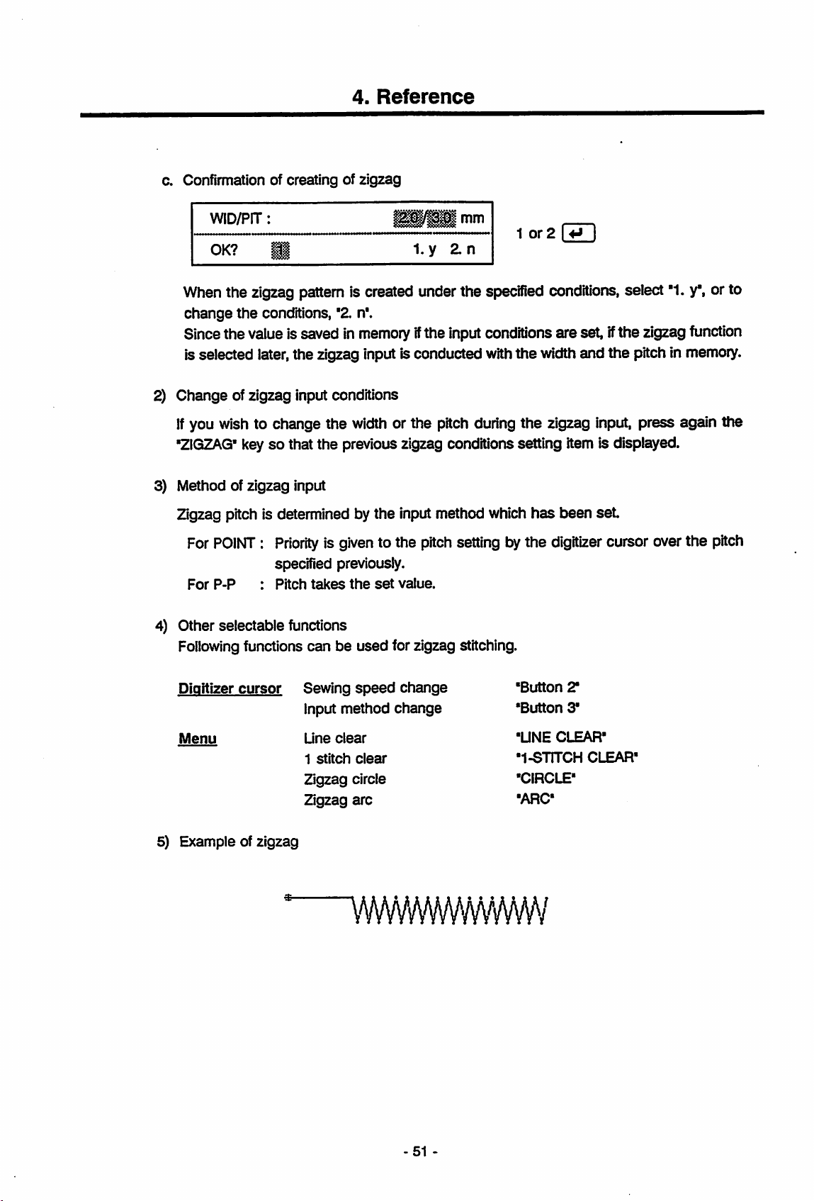
4.
Reference
c. Confirmation of creating of zigzag
WID/PIT:
OK?
®
Pi|/pMmm
l.y
^n
1
or2
r*n
Whenthe zigzag pattern is created under the specified conditions, select '1.
change
Sincethe value issaved in
the
conditions,
'2.
n*.
memoryifthe inputconditionsare set, ifthe zigzagfunction
is selected later,the zigzag input is conducted withthe widthand the pitch in memory.
2)
Change
If
you wish to change the
"ZIGZAG'
3) Method of zigzag input
Zigzag pitch is determined by the input method which
For
For
4) Other selectable functions
Following
of zigzag input conditions
width
or the pitch during the zigzag
input,
keysothat the previous zigzag conditions setting item is displayed.
has
been set.
POINT:Priority
is givento the pitchsetting by the digitizer cursor overthe pitch
specified previously.
P-P
:
Pitch
takes
the
set
value.
functions can be used for zigzag stitching.
press again the
y",
or to
Digitizer
Menu
cursor
5) Example of zigzag
Sewing
speed
Input method
Une
clear
1
stitch
clear
Zigzag circle
Zigzag
arc
wmmmmi
change
change
•Button
•Button
•UNE
CLEAR-
•1-STITCH
-CIRCLE-
-ARC-
2"
3'
CLEAR-
-51
-
Page 59

4.
Reference
6) Creation of zigzag circle
If
the
'CIRCLE' key is
created.
a Example 1 of zigzag circle
pressed
data
while making a zigzag data, a zigzag circle
data
data
can
be
Inputthestitchless feed
to put it in
points B
With
this example,
the
circleisdrawninclockwise
the
zigzag
andCso
that
the
data
from
the
data
input state. Input next
zigzag
zigzag
circle
data
direction.
dataO
are
origin
made
Oto
within
the
point A
the
'CIRCLE' key
- A - B C is
the
specified circle (at right)
and
press
created.
the
'ZIGZAG'key
and
specify
the
because
52-
Page 60

4.
Reference
b. Example 2 of zigzag circle
data
Inputthe stitchless feed data
data inputstate.
the
Example 1)sothat zigzag circle
With
this
example,
because
the
Input
next
the zigzag data are made at outside of specified
circleisdrawnincounterclockwise
from
the
'CIRCLE'
origin
Oto
the
pointAand put itunder the zigzag
keyand specifythe pointsC and B(contraiy to
data
O-A-C-Bis
direction.
obtained.
circle
(at
right)
-53
Page 61

4.
Reference
7) Creation of zigzag
if
the
'ARC
a. Example 1 of zigzag
key is input while making a zigzag data, a zigzag arc
arc
data
arc
data
data
can
be created.
Input
the
stitchless
input
state.
arc
data
0-A-B-Cls
With
this
example,
the
circleisdrawninclockwise
Input
feed
next
the
data
the
obtained.
zigzag
from
'ARC
dataare
direction.
the
key
origin
and
made
Otothe
speciiy
within
point
the
the
specified
Aandputit
points
Band0 so thata
circle
under
(at
right)
the
zigzag
zigzag
because
-54
Page 62

4.
Reference
b. Example 2 of zigzag
arc
data
Inputthe stitchless feed fromthe originOto the point Aand put itunder the zigzag data
input state. Input next
arc
data
O - A - C - Bisobtained.
With
this example, the zigzag data are made at outside of specified circle (at
because
the
circleisdrawnincounterclockwise
the
'ARC*
key and specify the points C
direction.
andBso
that a zigzag
right)
55
Page 63

4.
Reference
(27) Thread trimming
Thread
When
trimming
trimming
the last data isthe bastingdata, the thread basting code isinserted beforethe thread
code.
(28) Origin return
Stitchless feed
origin.
If
there is
position to
(29) End (END)
End
pattem
code
data
the
data
(TRIM)
code iscreated at the last position specifiedbeforethis function isselected.
(RTN)
data
is created from
the
input
second
second
origin in
is created at the last position specified before selecting this function,
mode
End code can be input only next to
thread
trimming.
the
origia
endsupand
the
last position before selecting this function to
pattern data,
the
the
stitchless feed (excludingthe basting code) or the
reset
the
stitchless feed
state
is established.
data
runs from
the
the
last
the
(30)
Straight
Pattem
However,in
line
data
the
pattem data, it is erased
iDe
(31) 1
erased
stitch
One
If
itis operated several times, the
onebyone
clear
stitch in
clear
(L-CLR)
(straight line, zigzag, circle or arc), which
caseofdata
(1-CLR)
the
pattem
which
was
created with any otherdevice
one
stitch by another. Ifitis operated several times,
starting from
data
which
data
the
last
data
was
input in
can
be erased one by one starting from the last
the
end,iserased.
was
input in
the
than
end, is erased.
PTN-A
or 2 bytes
the
data
data
can
-56-
Page 64

4.
Reference
(32) Function
Functioncode data is created at the last position specified before this function is selected.
Please notethat the pattern data containing the
bytesdata
1) Input of function
2)
a. Basting
code
writing*orwith
FUNCTION-CODE
7-30
Specify
Code
the
Nos. which
Function
Function code
Code
input
(FUNCT)
function
code
the
code
No.
code
canbeused
code
No.
No.
(BST-
*)
on-line
No.
to be
7
functionofPLK
input.
at present,
areasshown below.
Basting
function
Function
code 7 1^ I
code cannot be used
Series
code
8 Continuouscode 8 I ^ I
sewing
No.
7 to 30can be
machine.
with
the
specified.
"2
The
basting
presently
Basting
starts
from
stitchiess feed data are created after the completion of basting data,
is automatically programmed in front of these
When
data,Ina straight
created patternto the
line,isdrawn
position
to be specified next
from
the last
specified
position
data consistsofthe basting code and the stitchiess feed data and the
the basting code
itis
connected
with
position.Ifsuch data as thread
data
the
on-linewith PLK
Series
machine
trimming,
or 2
bytes
the
origin
basting
data
itis necessary to inserta sewing data of stitch or more in frontofthis basting code.
b.
Continuous
Continuous
floppy
With
PTN-A10,
cannot be done. Use
plural
Continuous
the
pattern
is
broughttothe
code
codeisusedtosew
diskand
allows
to create the pattern data of
continuously
the connection patternscan be created butthe processingofconnection
PTN-A40
connection patternsasa pattem).
code
is created at
data
inputisfinished
reset
state.
to process the connection (a process to record the
the
last position specified before this function is selected,
inthe same wayas the end code andthe
the
plural patterns
max.
savedinthe
32000 stitches.
input
on the
stitch
return,
code
is written,
same
system
57
Page 65
4.
Reference
Connection
pattern
Continuous code is used to make the pattern consisting of more than 8000 stitches.
Number
32000
ofpatterns
stitches
can
which
be
created.
can be combined is2 to 4 patterns. Pattemdata of a
Continuous pattern is created by following procedures.
Inputofleadino
Input
the pattem
8000thstitchand end the pattem inputmode. Selectthe
data
in a floppy disk.
Inputofmidpoint
Take
the
normal pattern input. Input
pattern
with
the standard
pattern
f2nd.
last stitch position on
the
method
3rd
oattems)
the
last preceding pattemasthe
continuous
and
code
input
the continuous code just
write
mode nextand save the
origin and conducts
just before 8000th stitch
and
pattem input mode. Select the write mode next and save the data in a floppy disk.
Inputoffinal
Take
normal pattern input. Input
input mode. Select
pattem
the
last stitch position on
the
write
the
last preceding pattemastheorigin and conducts
the
end
code
mode
just before 8000th stitch
next
and
save
the
data
and
in a floppy disk.
end
the
max.
before
end
pattem
the
the
the
sure
Make
continuous
(33)
Record
Ust of
screen.
are
list (RC
data
Display itemsfor 1
not
recorded
NO
Number
1) Selection of display
DISPLAY
Select
the
select "1. REG RAM' or, to display
Since
the
the
floppy
to write allconnection pattems into
code
between
the
stitch
data
US)
recorded on
are
of
stitches
the
indicated
:
Pattem
:
Number
record memory or
pattem
areasshown
with
No.
of
stitches
mark.
data
DATA:
REG
RAM
datatobe
display
diskonthe
•
Z
FLOPPY
displayed. If
you
the
startsassoonasthe
disk
drive.
data
display
the
same
floppydisk
and
the
stitchless
the
floppy disk is displayed on
below
but
items to which
^
1 or 2 I I
wish to display
the
of floppy disk, select "2.
data
is selected,besuretoset
feed
...
t . )
dataonthe
and
not to input
data
the
record memory,
FLOPPY".
the
LCD
pattem
data
beforehand
the
58-
Page 66

4.
2) Example of record list display
Reference
Display
selected.
Record
3) Operation after
Following
shown above represents the case when the data of record
No.
is displayed
the
data
with
3 digits
display
figure
and the stitch number
keys canbeoperated after the display of recorded
+ : List of next 4 patterns
- : List of preceding 4 patterns
CANCEL
or[3:
RCUSfunction
are
is ended.
displayed.
are
displayed.
(34) Pattern list (FT LIS)
List
ofpattern datawhichhave been saved inthe floppydiskor
canbedisplayed on the
LCD.
Ust of 2 bytes
data
cannot be displayed.
Items displayed for a pattern areasshown below. The items to which
not
Data
recorded
onaflooov
are
indicated
disk
with*mark.
data
PROM
memory
with
4 digits
has been
figure.
under the writemode,
the
pattern data are
No.
Pattern
Number
Data
No.
Number
name
of
onaPROM
of
stitches:Numberofstitches
stitches
1) Selection of display
DISPLAY
1.
DATA:
FLOPPY
Pattern
Pattern
Pattem
:
Number
data
No.
name
No.
of
Datafor display can be selected.Ifyou
•1.
FLOPPY" or, if it isona PROM,
stitches
PROM
select
1or2 L+J
like
to display any data on a
"2. PROM".
floppy
disk, select
59
Page 67

4.
Reference
2) Selection of No. to start
(Thisis displayed only at
DISPLAY
1.
Pattern No. to start
No.100,
Since
the
floppyonthe
3) Selectionof kinds of
PROM
1.
Select the kindof
select
'1.27256",orif it is
Since
the
PROM which
START
100
the
select
*1.100"
display
startsassoonasthe
disk drive.
PROM
27256
PROM
display startsassoonasthe
contains
the
display
the
display of floppy disk
NO.
data)
1or2 (5ZI
Z
180
display
or, if it is
inwhichthe datato display are saved.Ifitis the
the
can
No.180,
(This
is displayed
2.
27512
the
PROM
datainthe
be
selected. If you like to
select
numberisselected,
*2.180".
only
at the displayof
1or2
27512,
kind of
PROM
select
socket
"2. 27512".
PROM
beforehand.
start
be
suretoset
[3
is selected,
the
PROM
be
suretoset
display from
beforehand
data)
PROM
27256,
a
the
4) Example of pattem list display
% ^ „
Above
Pattem
displayed.
In
displayed. Display
5)
Operation
Following
screen shows the case of data display
No.
in 3
thecase of
afterthe data
digits,
PROM
pattern
data,
the pattem
and
key operation
display
keyscan be operated
+ :
— :
CANCEL
orl»^I:PT LIS
List
of next 2 pattems are displayed.
List
of preceding 2 pattems are displayed.
functionisended.
fromafloppy
name in 8
No.
are
(At
the display of
while
the pattern data are displayed.
digits
in3
digits
the
sameasthe
and
andthe
floppy
disk.
stitch
number in 5
stitch
record
diskdata)
number
list
in4
digits
digits
are
are
60
Page 68

4^
Read
Data
Mode
for1pattern
(equivalentto27256or27512),
Please note that, if
(1) Selection of read mode
(adapted to
PLX-A
can be read.
the
reading is executed,
4.
Reference
Series),
the
which
pattern
are
data
written
in memory
in a
floppy
are
disk or a
erased.
PROM
Select
*2.
READ"
(2) Operation to read
1) Pattern No. input
PATTERN
F:
100-249
Specifythe No. of pattern to read.
249 to
2) Selection of
read
PROM
1.
the
kindofPROM
27256
Select the kinds of
PROM
27256or"2.
under
No.
data
the
reset
state.
R:
0-15
Initial
display on the screen is No.100. Input100 to
from a floppy disk or 0 to 15toread
(This
is displayed onlyat the reading from a
2.
27512
PROM
27512"
to which
foraPROM
the
desired pattem is written.
2751Z
Specify
the
1 or 2
the pattern
data
from a PROM.
r»ri
Select
No.
i ^ 1
PROM)
"1.27256" for a
3) Confirmation of execution of reading
No.
READ?
Select
: 1
1
"1.
y"to read under the specified conditions or "2. n"to
1. y 2. n
Since the reading startsassoon as '1.y"is selected, be sure to
PROM, in
(3) Read of
Connection
the
disk drive or in
connection
pattem,
pattern
which
the
PROM
has been made
socket
with
(Reading isexecuted but the data are not proper ones.)
61
1or2
beforehand.
PTN-A40,
change
set
a floppydisk or a
cannot be read
the
conditions.
with
PTN-A10.
Page 69

4.
Reference
(4) Display of
1)
When
Pattern No., pattern name and number ofstitches in memory are displayed on
2)
Whenapatternona PROM is
Pattern No., pattern
endofreading
a pattern on a floppy disk is read.
FLOPPY
NAME:
read.
PROM
name
and
number
of stitches in memory
are
displayed on
the
the
LCD.
LCD.
62
Page 70

4.3
Write
Mode
4.
Reference
Pattern
are
Data
of
(1) Selection of write mode
(2) Operation to write
data
(adaptedtoPLK-A
written
the
Select
1) Selection of
2) Input of pattern
ona
floppy
writing
cannotbeconducted
pattern
data
"3. WRITE"
DESTINATION
1.
Select the destination to writethe pattern
diskor"2. PROM"towriteona PROM.
(Thisisdisplayed
disk
under
writing
FLOPPY
name
onlyatwriting
Series)
ora
PROM
unless
the
reset
destination
which
have
been
completed
(equivalentto27256or27512).
thereIstheend
state.
PROM
the
pattern
data
ona
code
orthe
1
or2
Select "1.
floppy
disk.)
and
retained
continuous
FLOPPY"
inthe
system
code
attheend
to writeon a floppy
PATTERN
Input
the pattern name to be assigned at
"PATTERN"
canbe
method, refer to "2.2Operating Method,
3)
SelectionofkindofPROM
Select the kind of
PROM
input
PROM
1.
27256or"2.
NAME
is preset at the pattern name.Ifyou
with
the
alphanumeric
(Thisisdisplayed
27256
PROM
27512"
2.
which retains the pattern to read. Select
for
the
character
27512
PROM
writing.
oflessthan8
(3)
Howto
only
27512.
like
to change
key-in
atthe
1
digits.
the
reading
or2[^
it,
a new pattern name
Regarding
menu".
pattern
fromaPROM)
"1.
27256"
the
for the
input
-63
Page 71

4.
Reference
4) Confirmation of execution of writing
WRITE?
B
1. y 2. n
1
or2
I ^ I
Select
"1.
Since the
PROM, in
(3) Display of
1) When
Pattern
2) When writing on a
Pattern
end
writing
FLOPPY
NAME:
No.,
PROM
No.
y to write under the specified conditions or "2.n"to changethe conditions.
writing
the
starts as soonas'1.y*is selected, be sure to
disk
driveorin
the
PROM
socket
set
a floppy disk or a
of writing
on a floppy disk
No.
tm
pattern name and number ofstitches
written
are displayed on the
LCD.
PROM
No.
and number ofstitches
:
c
written
are displayedon the
LCD.
64-
Page 72

4.4
Function
Selecting
Mode
4.
Reference
Inaddition to
write/read of
(1)
Selectionoffunction
Select
(2)
Selectable
the
data
'4.
FUNCTION'
1.
FLOPPY/PROM
Z 2
3.
RECORD
4.
ONUNE
6.
SERIAL
7.
SERIAL
pattern input, read
for
PLK
Series (2 bytes data)
selecting
under
functions
BYTE
DATA
I/O
DELETE
RECEIVE
TRANSMIT
and
mode
the
reset
HANDLE
5.
write,there
state.
MODIFY
are
such
functionsasthe
and
a few otherfunctions.
floppy disk format,
stitch
Menu
Tablet
:
1.
Floppy
disk, PROM
2. Read/write of 2
3. Erasing of
4.
On-line
5.
Correction
6. SIC
7. SIC
8.
9.
10.
data
data
Test
Record
Pattern
recorded
input
output
list
list
bytes
operation
pattern
data
•r
•2"
•3'
•4'
•5'
•6"
.7.
•RECORD
•PATTERN
USP
USP
-65
Page 73
(3) Operation of floppy/PROM
Floppy disk
PROM
Is processed.
and
1) Selectable function
1.
2.
3.
PATTERN
FLOPPY
PROM
DELETE
FORMAT
COPY
4.
Reference
STITCH
:
Menu 1. Deleting of pattern
2. Floppy disk format
3. Copy of PROM
2) Deleting of pattern
Patterns
a
Pattern
input
b.
Confirmation
writtenona floppy disk
No. input
PATTERN
F:
100-249
the
No.
pattern
of
data
No.todelete,
deletion
are
data
deleted.
•1'
'2r
•3-
Specify
the
No.
(ZD
No.
DELETE?
Select
Sincethe
the
disk
: ^
g
*1.
y' to delete underthe specifiedconditionsor '2.n*to changethe conditions.
deleting
drive
starts as soon as
beforehand.
FLOPPY
1. y 2. n
"1.y"is selected, be sure to set the
66-
1
or2
I V I
floppy
diskin
Page 74

3) Floppy disk format
Format
Typeof
a
(Initialize)
format
Confirmation
DISK
FORMAT?
isdetermined
of
FORMAT
4.
Reference
the floppy disk to enable the write/record.
with
executionofformat
S
setting of dip
i.y
2.n
switch
at the touch up of inputsystem.
1
or2
I
Select
Since
disk
4) Copy of PROM
Contents in a
"1.y*to executethe
the
format startsassoonas'1.y'is selected,besuretoset
drive
beforehand.
PROM
is copied to another
Both the original and the copy
Contents of copy
a
Selection1of
PROM
1.
256
Specify the
PROM
b.
Selection2of
27512
(Thisisdisplayed
PROM
PROM
kindofPROM
2.
512
kindofPROM
or "3. OTHER"for
kindofPROM
only
formator"2.n"to abort the function withoutformat
a floppy disk in
PROM.
PROMs
must be cleared before copying.
3.
OTHER
to copy. Select
any
when
"3.
OTHER"
must be the
"1.
other
PROM.
256"
same
ROM
forthe
type of
No.
PROM
was selected inthe Selection 1
the
[HD
27256,'Z512"
the
same maker.
forthe
above.)
1.32A
Specify
PROM2732, "3.16" for
c. Confirmation of
PROM
COPY?
Select
Since
PROMatthe
"1.y"to copy under the specified conditions or
copying
2.32
the
kindofPROMtocopy.
COPY
B
socket1and
3.16
the
PROM2716 or "4. 64"for
executionofcopy
startsas soon as
the
4.64
Select
1.y
"1.
2.
n
"1.y"isselected, be sure to set beforehandthe
coov
PROMatthe
67
ROM No. I I
32A'forthe
1or2 ®
socket
PROM
the
PROM 2764.
"2.
n"to change the conditions.
2.
2732A,
"2.32"
forthe
oricinal
Page 75

(4) 2 bytes data I/O
data
Pattern
read
or
1)
Selectable
(2 bytes data) adaptable to the conventional electronic sewing machines
written.
functions
1.
DATA
Z
DATA
READ
WRITE
4.
Reference
are
(ZD
STITCH
Menu 1.
2)
Reading
Data
are
of 2
read
bytes
a Pattern No. input
PATTERN
0-9
Input
the
pattern
b.
Selection
1ofkindofPROM
PROM
:
Data
reading
Z
Data
writing
data
from a PROMwhich
No.
No. to
read.
'1'
'Z
stores2bytes
The
number
data
Pattern No. I |
canbeselected
out
of 0 to 9.
1.
256
Select
the
PROM27512 or "3.
c.
Selection2of
(Thisis displayed only when
PROM
1.
32A
Select
PROM
the
2732or*3. 16*
2.
512
3.
OTHER
kind of PROM to read.
OTHER*
kindofPROM
for
*3.
2.
32
kind of
PROM
for
3.
16
to read. Select
the
PROM
Select
any
other
OTHER"
2716.
-68
"1. 256" for
PROM.
was selected with the Selection 1 above.)
•
*1.
32A*
for
ROM
No.
the
PROM 27256, "2. 512" for
ROM No. l4-» 1
the
PROM
2732A,'Z32'
for
the
the
Page 76

d. Confirmation of reading
4.
Reference
NO.
READ?
Select
Since
PROM
Settinc
: P
p
*1.
y to read under the specified conditions or '2. n' to change
the
reading
socket
of
PROM
QtyofPROMs
1
2
e. Confirmation of
PROM
startsassoonas'1.
beforehand.
Settingisconductedasshown
endofreading
l.y
Socket
PROM
set
Setting of
y" is
1st
an
selected,
1
PROM
1or2 [ ^ I
be
suretoset
below.
Not
Setting of
Socket
used
the
conditions.
the
PROMatthe
2
2nd
PROM
Pattern No.
3) Writing of 2
Pattern
When
the
automatically
a
Selection
PROM
1.256
Select
PROM
b.
Selection2of
and
number of stitches, which have
bytes
data
which is retainedatpresentinthe
last
partofthe
there.
1ofkindofPROM.
2.512
the
kind
of PROMtowrite.
27512or"3.
kindofPROM
(This is displayed only when
PROM
1.32A
2.32
data
OTHER'
retained
3.
OTHER
for
"3.
3.16
been
read,
input
system,
pattern
dataisnot
the
end
ROM No. I ^ I
Select
any
other
"1. 256"
PROM.
for
the
OTHER'was selected with
ROM
are
displayed on
is writtenonthe
code,
the
PROM
27256,
the
Selection 1 above.)
No.
the
LCD.
PROM.
codeisadded
512"
for
the
Select
PROM
the
kind of PROMtowrite.
2732or'3.16'
for
the
PROM
Select
2716.
69
"1.
32A'
for
the
PROM
2732A,
'2.
32*
for
the
Page 77

4.
Reference
c. Input of
Input
d. Confirmation of writing
Select '1. y to
Since
PROM
e. Display of
number
PROM
the
number
WRiTE?
the
socket Itcan be set in the same wayas2) Reading of2 bytes
PROM
of PROMs
NUMBER
of PROMtowrite.
write
under the specifiedconditionsor "Z n"to change the conditions.
writingstartsassoonas"1.
end
of writing
No.
Select1or
1. y Z n
y is selected,
:
mmm)
Number
Z
1or2 \ ^ I
be
suretoset
c
I
the
PROMatthe
data
Pattern
The
used.
(5) Deleting
Data recorded on a
This
isthe
(6) On-line
When
system
For further details, refer to *4.5On-line Function*.
(7) Modification
Pattern
machine.)
This
isthe
For further details, refer to
No.
and number ofstitches are displayed on the
youngest
the
same
the
systemisconnected
pattern
recorded
RAM
functionas'4.1
canbemodified.
data
retainedinthe
same
functionas*4.1
No.isautomatically
data
or a
floppy
disk are deleted.
Pattern
withasewing
This
isthe
same
systemismodified
Pattern
*4.6
Modification Function".
selected
input
Mode,
machine,
functionas'4.1
(thereisno
Input
Mode,
LCD.
from
the
(9)
Deleting
the
pattern
Pattern
connection
(11)
Modification".
numbers
the
recorded
data
Input
Mode,
which
are
not
data*.
retainedinthe
(10)
On-line".
with
the
sewing
yet
-70
Page 78

(8) Serial receiving
4.
Reference
Patterndata for1 patternis received
from
an externaldeviceviathe
RS-232C
serialinterface.
Please note that, ifthis functionis executed, the pattern data retained inthe input system is
cleared.
Connect
leftside of main unit of input system
1) Confirmation of receiving
2) Display of result of receiving
one
end
SERIAL
RECEIVE?
Select
input function.
"1.y"to read the pattern data fromthe external device or
of RS-232G serial interface with
and
the
RECEIVE
1. y 2. n
other
the
end
RS-232C
connector
with
the
external device.
1 or 2 I ^ I
As '1. y is selected, the input system becomes ready to receive
that you
can
RECEIVE
transmit
STITCH
the
pattem
:
data
from
the
external device.
providedonthe
*2.
n"to
end
the
communication
the
serial
so
C
When
displayed.
(9) Serial
the data
transmission
receivingiscompleted,
the numberofstitchesof
Pattemdata for1 pattemis transmitted to the extemaldevice
etc.) via
For further details, referto
(10)
Test
Donot
If
*1.
the
RS-232C serial interface.
*4.1
Pattern Input Mode, "(12)Serial transmission*.
use
this function because itIsused onlywhen the system isshippedfromthefactory.
PROM
TEST*
is selected, the
PROM
which is
set
or the internal data maybe distorted. Be sure to removeit
When
button
*2.
TABLET
4 of
TEST'was selected by mistake, hold down the button 2
the
digitizer cursor.
at the
received
(electronic
PROM
socket maybedestroyed
from
the socket beforehand.
sewing
pattemdata is
machine,
and
press the
71
-
Page 79

(11) Record list
4.
Reference
Listofdata
saved in the record memory or
items for 1 pattern are as shown
items,
such
items
are
This is the
Display
(12)
Pattern
List of pattern
the
LCD. List of 2
Display items for 1
indicated
This is
Data
same
item
No.
Number
list
with
the
same
onaflooov
No.
Pattern
Number
functionas'4.1 Pattern Input Mode, (33) Record
of
stitches:Number
data
written with
bytes
pattem
mark.
functionas"4.1
disk
name
of
stitches:Number
indicated
:
Pattern
data
areasshown
:
Pattem
:
Pattern
the
floppy disk is displayed on
below.
When the pattern data are not recorded in any
with * mark.
No.
of
stitches
the
write
mode
on a floppy disk or a PROMis displayed on
cannotbedisplayed.
below. Items which
Pattem Input Mode, (34)
No.
name
of
stitches
list*.
havenorecorded
Pattem
list*.
the
LCD.
pattern
Display
are
Data
onaPROM
No.
Number
:
of
stitches:Number
Pattem
No.
of
stitches
72-
Page 80

4.5
On-line
Function
4.
Reference
Whenthe system is connected
system
can
be
modified.
Thisfunction can be selected
(1) Preparation
Following
Make
suretoturn
starting
1) Corrfirmation of
Confirm
insertportofthe
has
before
using
preparation is required before using the on-line function.
off
all
power
the
preparation.
cassette
that the cassette printed
main
the
on-line
connector
_ . Interface
P'ate
Thumb
screw
with
a sewing machine,the pattern data retained in the input
from
tx)ththe patterninput mode and the function seiectingmode.
the
on-line
suppliesand disconnect the
power
supply
connectors
printed circuit board
circuit
unitofsewing
as
shown
On-line
board,
machine,
below.
connector
which
is located at the
is a cassette
PROM
printed
cassette
PROM
circuit
connector
unit
cassette
board
before
which
Connecting
fto
2)
Pattern
Set
Settingofjumper
3)
the
selection
pattern
input
Thumb
cable
system)
screw
selecting
pin
Setting of jumper pins on the
seriesof
and
Change
C0N13
PLK
Series
PLK-A
sewing
machine
pins which
the
settingasshown
: 0
Series
: N
N O N O
PTN-2-lf=B
PTN-3-IFB
dialto'0*.
PTN-A10
printed
to be connected. Jumper
are
marked
side
side
"NONO".
beiow.
On-line
connector
plug
PCB Ona
PCB
circuit
pins
Cassette
case)
board
PCB
varies
depending on the
to be changedarethe
C0N12
Above example
C0N12
shows
the
setting for
C0N13
-73
PLK-A
series.
Page 81

4.
Reference
4) Connection with
input
and
the
a
Disconnect
b. Insert
the
Different
connected
When
below.
system
interface unit is
+
and
connecting cable.
the
the
interface unitsothat
interface units are used depending on the series of sewing machine to be
as
PLX
Series
PLX-ASeries:
PTN-3-IFB
5V
the
main unit of sewing machine
the
main unit of sewing machine
PROMorthe
one
shown
below.
:
PTN-2.IFBorPTN-S-IFB
PTN-3-IFB
PROM
way only. Do not tiy to insert forcibly.
cassette.
the
on-lineconnectoris
are
connected
set
via
the
interface unit
in positioa Directionto insert
is used, change the setting ofjumper pins on the board as shown
PLK
Series
+ 5 V
PLK-A
J3
Series
J2
J 1
A1
2
GND
c.
Lock
the
d.
Insert
one
specified to only
interface
endofconnecting
unit
withapairofthumb
cableinthe
one
end.
e. Connectthe otherend ofcableto the
of
input
system and
lock
firmly
a pairofscrews at both ends ofthe connector.
A1
GND
screwsatboth
interface
on-line
connecterlocatedat
J2
2
unit.
sidesofcassette
Pins
and
theshapeofhole
left
side of
insert
main
port
are
unit
Note:Atthe
shipping
from
the
factory,
74
the
jumper
pins
areset
for
the
"PLK
Series".
Page 82

(2) Selection of on-line function
Make
the
Dreparation.
of
sewing
machine.
selecting mode.
touch
Select
4.
Reference
up
the
input
"5. ONLINE"
system
under
and
the
stateor"4.
then
turnonthe
ONLINE'
powerofthe
under
the
main
function
unit
(3) Execution of
As
the
Whenthe message is shown, turn on the
resetatthe
sewing machine
on-line function is initiated, following
M090:
PLK
RESETTING
RESET
side
message
willbeshown.
key ofsewing machine andthen input the
CANCEL key of PTN-A10.
After
the
CANCEL
Reset the sewing machine
keywas inputted, respective functions of on-line can be selected.
Caution
positively
before operating the
CANCEL
key of
PTN-A10.
(4) Specification of stitch (position) to be modified.
If
the
following
function, the machine operates as directed with the pattern
presentbythe
sewing machine operating keys are operated after entering in the on-line
data
which are retained at
input
system.
Operate the machine as described above and feed the sewing needle to the position to
modify
and
display.
Sewinc
machine
ooeratino
kevs
which
can
be
used
Operationwiththe keys is sameasthat of the sewing machine.
Origin return
Inching +
Inching -
(5) Change in pattern data after
Whenthe pattern data is ended
and
"End code"
However, when a code
"End
code"
(JOG+)
(JOB-)
data
(RETURN)
data
are newly created if
data
is contained in the
are
created
from
the
execution of on-line modification
with
"Origin
the
code
75-
return"
the
data.
or 'End code", the data of'Origin
following operation is conducted.
"Origin
return" data,
the
"Origin
return"
return"
and
Page 83

4.
Reference
Functions
which
change
• Stitch position modification
• Erasing of stitch
•
Additionofstitch
Examole
of
o
Origin
change
in
data
the
data
ferasino
Erasure
of
stitch)
-o
Erasing of
Additionofcode
code
Origin
(6)
Selectable
functions
1.
^
3.
5.
6.
7.
MODIFY
MODIFY
ELSTCH
ELCODE
ADCODE
DATA
STITCH
SPEED
DISPLAY
STITOH : i
Menu 1. Modify stitch
2. Modify
3.
Eliminate
4.
Add
5.
Eliminate
6.
Add
7.
Data
speed
stitch
stitch
code
code
display
4.
ADSTCH
•1"
•2"
•3"
-4-
•5"
•6"
•7'
76-
Page 84

(7) Modificationof stitch position
4.
Reference
Stitch position of pattern data is
modified.
1) Inputof move and distance inXdirection
X
DIRECTION/DISTANCE
1.
+
2.
—
mm
Movement distance is input separateiy for X and Yaxes.
Inputatfirst
input
direction
the moveinXdirection.
To
move
the
stitch
to
this
side.
To
move
the
stitch
to
other
side.
To
move
the
stitch
to
left
To
move
the
stitch
Directionisas
direction
-Y
direction
+Y
direction
-X
direction
to right. +X
shown
below.
Operator
As the input of
movement distance. Input
2)
Input
of moveand distance in Ydirection
X DIRECTION/DISTANCE
1.
+
If
the
movement distance in X direction is input,
move
direction is
the
2.
-
over,
the cursor moves to the
distance in mm unit underthis state.
the
display
changestothe
position
to input the
inputthe move and distance inYdirection. Input inthe same mannerasXdirection.
3) Selection of modifying
MDSTITCH
1.
STITCH
Method of modification is selected. When only
position,
select
"1.
specified position.
method
TYPE
2.
STITGH"or*2.
PATTERN
PATTERN"
1^1
one
stitch is
changed
at the specified
to change also the data subsequent to the
screen
to
77
Page 85

4.
Reference
4) Confirmation of execution of modification
Select"1.y to modify
the
conditions.
At
the
moment
specified with
5) Data (stitch) to
Specify
it is
When
create
than3mm.
the
sewing or
rejectedaserrors.
the
stitchless
the
data
OK?
mm
when
the
needleofconnected
be
specified
withwhich
Y:
the
stitch position under
the
confirmation No. is input,
the
stitchless feed for
feed
t>ecomes larger
the
1. y 2. n
mm
the
specified conditions or '2.n*to
sewing machine is modified.
the
pattern. Ifany
than
3 mm after a
feed is dividedsothat
1
stitch
modification
1or2 I I
the
data,orthe
the
feed
becomes
subsequent
other
data
are
specified,
changeofstitchless
automatically
change
data,
feed,
less
-o-
Relative
modification
O
o-
O O o
4 4 i
-78
Page 86

4.
Reference
(8) Modification of sewing
Sewing
speed
of pattern
speed
data
is modified.
1) Input ofstitch number to be modified.
STTTCH
1
io
Number of stitch of which
Whenthe speed is
•LASP
is
When
isdisplayed atthe stitchnumber
changed.
the
stitchlessfeed or
are neglected and the speed ofsewingdata
2)
Selectionofsewing
SEWING
1.
H
2.
SPEED
M1
1
the
modified
speed
3.
M2
the
•i
sewing
stch
speedischanged,isinput
Modifying
up to the last stitch, operate the
input
code
4.L
position
is included in
within
andthe speed up to the laststitch
the
specifiedstitch number,
the stitch number
Specified
stitchnumber 1 I
"LASP
speed
keyon the
these
only
is changed.
No.I-H
|
menu.
data
Specifythe sewing
Initially,
the speed of data
entered inthis
the sewingwas indicated, '4L
speed
function,
after modification withthe No. "1' to
which
was indicated
isdisplayed at the
(Low
speed)" is displayed.
No.
with
the sewingmachine needle whenit
input
position.
'4*.
Whenany data otherthan
3) Confirmation of execution of modification
1
Ml
1. y 2. n
1or2
specified
No.
is input, the sewing data subsequent to the
conditionsor"2.
MDSPEED
SPEED:
Select
conditions.
"1.y"to
p
modify
STITCH:
the speed underthe
Atthe moment when the confirmation
data Indicated withthe needle of connected sewing machine, are modified.
4)
Data
(stitch) to
It is optional
specified with
be
specified
the
data
which is
the
machine needle.
Modification
1
stitch
only
of
n' to change the
-79
\}
Modification
Page 87

4.
Reference
(9) Eliminating of
Stitches of pattern
1) input of eliminating stitch
Input
stitch
data
are
eliminated.
number
STITCH
the number of stitches to be eliminated. When eliminating the data up to the last
stitchposition, inputthe 'LASP key. "LASP
position. Be
suretocount
the
code
2) Confirmation of execution of eliminationg
ELSTITCH
Select
"1.
y to
conditions.Atthe
the
data
specified
In
such a case
rejectedasan
STCH:
OK?
eliminate
stitches underthe
moment
with
the
whenawrong
error.
when
machine
Eliminatingstitch number I
will
be displayed at the stitch number input
dataas1 stitch.
1. y Z n
the
confirmation
needle
specified
are
1or2 i \
conditions
No.isinput,
eliminated.
data is createdifthe specified
or '2.n"to changethe
the data subsequentto
eliminating
is done, itis
3) Data
(stitch)
to be specified
Itis optional the data which is specified with
the
machine needle.
Eliminating of
1
stitch
only
80-
Page 88

(10) Addition of stitch
4.
Reference
Pattern
What
data
are
added.
canbeadded
withthis function is
the
sewing
dataorthe
stitchiess
feed
data
Which
ofthe sewing data or the stitchiess feed is added, itis determined automaticallyby the input
system depending on
1) Selection
Method of addition is
a straight line
Method
ADD
1.
adding
METHOD
STITCH
of
addition
1
stitch
data
the
state of adding position.
method
UNE
selected.
addition
Select
'1.
STITCH*toadd
Addition
1
or2l
1
1 stitch onlyor'2.
in Y
direction
UNE'toadd
Additionofstraioht
o O
Addition
line
Stitch
in X
direction
length
Addition in X
direction
V
Addition
O O
in Y direction
-81
Page 89

4.
Reference
2) input of move
X
Y DIRECTION/DISTANCE
1. +
Movedistance mustbeinput separately for X
at
the
modification of stitch position.
3)
Input
ofstitch length pisplayed onlyat the addition ofstraight
STITCH
Itisinput
2)
above,
specified
distance
DIRECTION/DISTANCE
2.
- ®
LENGTH
with
how
are
divided.Inthecaseof
hereisneglected
of additional
D
much
stitch
and
data
length
addition
the
dataiscreated
mm
PPP
theX,Y
1or2 Move
1 or 2 Move distance mm I ** I
and
Y direction. Input method is
line.)
mm
ofstitchless
Stitch length mm I I
move
distancedata,
feed,
however,
with
the
move distance of 3 mm.
distance
which
the
mm \ ^ i
same
was
input
stitch
length
as
at
4) Selection of sewing
SEWING
H 2. M1
Select
However,
neglected.
5) Confirmation of execution of additional stitch
the
speed
inthe case of
ADSTCH
speed
SPEED
3.
of stitches to
OK?
M2
4.
L
be
addition
added
of stitchless feed data, the
with
m 1. y 2. n
•
ADLINE
OK?
^
1.y2.
m m 1
Contents of disolav
Move
distanceofX(mm)
2)
X . Y
(from
left)
Move
distanceofY(mm)1stitch
the
No. of 'I* to
n1
Specified
1 or 2
1
or2
I I
length
3)
sewing
rrn
speed
'4'.
(mm)
No.
I ** 1
specified
Sewing
here is
speed
4)
-82
Page 90

4.
Reference
Select '1. y to add the stitch under the specified conditions or '2. n' to change the
conditions.
At
the
momentwhen
data specified
the
confirmation No. is input,
with
the needle ofconnected sewing machine.
the
specified
dataisadded
next to
6) Data (stitch) to be specified
the
(11)
Code
Tableofcode
itis optional the data specified
table
No.
2
V
data
which
are
Thread trimming
0 o o o ^ ®
data
Code
valid
Function
with
the machine needle.
Addition
...
Addition
straight
under
the
on-line
code
of1stitch
of
line
functionisshown
below.
4
5
6
7
31
(12) Eliminating of
Code data in
the
Midpoint
Reverse
2nd
origin
Basting
End
code
pattern data is eliminated.
1) Input of code No.to be eliminated.
ELMINATE
CODE
input of code No.to be eliminated.
code
No.
stop
code
code
code
code
Code
No. I ^ I
-83
Page 91

4.
Reference
2) Confirmation of execution of eliminating
ELCODE
OK?
Select
conditions. In
from
is eliminated. When there
smallest
In
rejectedasan
3) Data (stitch) tobespecified
It is optional
*1.y*to eliminate
the
moment when
the
data
specified with
stitch
numberiseliminated.
such
occasion when a wrong
error.
the
data
the
specified with
1?
CODE:
1
or2
M
code
the
are
"i.y
2.n
under
the
specified conditions or '2.n'to
the
confirmationNo.is input,
needle of connected sewing machine to
more than
data
the
one
specified codes, only
is created ifthe specified eliminatingis done, it is
machine needle.
I^ I
the
specified
one
1*^
change
code
starting
the
last stitch,
codeofthe
the
(13) Additionofcode
Code data is added to the pattern
1) Input of additional
ADD
CODE
Input
the
additional
2) Confirmation of
ADCODE
Select
"1.
y to add
code
No.
executionofaddition
conditions.Inthe
added
In
rejectedasan
such
next
tothe
occasion
data
whenawrong
error.
code
with
OK?
the
code
moment
specified
data
the
code
• 1-y
under
when
the
the
confirmation
with
the
data is
Code
No.
2.n
specified
1 or 2 1v 1
conditionsor"2.n"to
No.isinput,
needleofconnected
createdifthe
specified
No. 1^ I
the
specified
sewing
machine.
additionisdone,itis
change
code
the
is
84-
Page 92
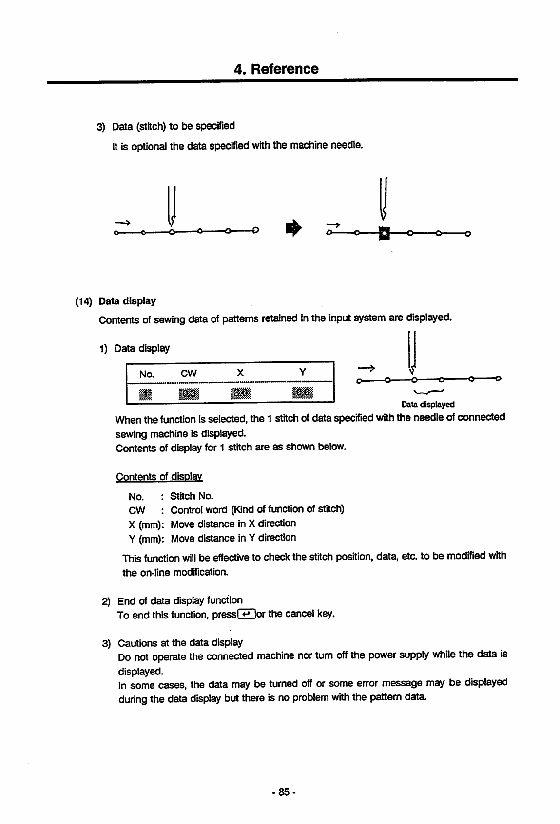
4.
Reference
3) Data
(14) Data display
(stitch)
Itis
optional
o ^ O O O O
Contents of
1) Data display
No.
•
When the functionis selected, the 1 stitch ofdataspecified withthe needle of connected
sewing machine is displayed.
Contents of displayfor 1 stitch are as shown
to be specified
the data specified
sewing
data ofpatterns
CW
m
with
the
machine
retained
X
•
inthe
Y
•
needle.
o
input
o-
systemare
-O
displayed.
Data
displayed
O o
below.
Contents
No.
CW
X (mm)
Y (mm):
Thisfunction
the
2) End of data display function
To end this
3) Cautions at
Do
displayed.
In
some cases, the data
during
on-line
not
of
disolav
Stitch
Control word
Move
Move
modification.
function,
the
operate
the data
No.
(Kind
distance
distance
willbeeffective
pressEor
data display
the
connected
maybeturned
display
butthereis no
offunction ofstitch)
in X
direction
in Y
direction
to check the stitch position, data, etc. to be modified
the cancel
machine
key.
nor
turn
off
the
off
or some error message
problem
with
the
power
pattern
supply
data
while
may
be displayed
the
with
data
is
-85-
Page 93

4.6
Modification
Function
4.
Reference
Pattern
data
retained in
the
Thisfunctioncan be selected
(1) Data
(2)
type
input
When
the
modifyingfunction is selected
if
the
data
type is not set. Data type for modificationis
sewing machine is
electronic sewing machine.
DATATYPE
1.
Pl-K-A
PLK-A
PLK
Selectable
1.
Z
Series
Series
function
ROTATE
ENLARGE
PLK-A
: 1
:
(REDUCE)
input
system
from
boththe pattem inputmode
are
under
modified.
the
function selecting mode, this is displayed
selected
Series electronic sewing machine or
2.
PLK
and
the function selecting mode.
depending on whether
the
conventional
PLK
the
Series
STITCH;
(3)
Menu
Rotation
1.
2.
Pattem data is rotated
1) Selection of
pisplayed
STARTING
1.
Selectthe
or
"2.
ORIGINAL*
This
function
*
Rotate
Enlarge
rotation
only
HOME
rotation
(reduce)
with
an optional angle.
start
position
whenthe data has 2nd
POINT
start
position.
ORIGINAL
Select
•1"
•2"
origin.)
"1.
HOME*
to rotatethe pattern afterthe 2nd
cannot be selected unlessthere isthe 2nd
1
or2
I I
to rotatethe pattem
origin.
origin.
from
the
origin
-86-
Page 94

2) Selection of rotating direction
DiRECTiON
4.
Reference
2.
in
LEFT
angleis0.1to90®
1. y 2. n
specified
conditionsor*2.n"to change the
1.
RIGHT
Direction of rotation is selected. Select "1. RIQHPtoturn to rightor
left
3) Input of rotation
ANGLE
Rotation
4) Confirmation of execution of rotation
Select
angle
ROTATE
"1.
y to
angle
isinput
OK?
DRCT:
rotate
Rangeofinput
underthe
1or2 I ** I
Rotation angle I ^ I
with
1 or 2 I ^ I
the
minimum
*2.
LEFT*
to turn to
scaleof0.1®.
conditions.
(4) Enlargement (reduction)
Pattern data is enlarged or reduced
1)
Selectionofenlargement
STARTING
1
HOME
Enlargement
'2.
ORIGINAL"
This function
2) Input of magnification
PERCENTAGE
X:
m&m
POINT
start
positionisselected.
to enlarge the pattern after the 2nd origin.
cannotbeselected
%
Y:
Magnificationisinput.Itcanbe
of
1%.Ifthe
magnification
valueisautomatically
set
start
mmi
ofX
butitis
with
an optionalmagnification.
position
(Displayed
ORIGINAL
Select
unless
%
inputinthe
thereisthe
'1.
range
directionisspecified,
possible
totake
only
when
2nd
origin
lor2[^
HOME'toenlarge
2nd
origin.
X
Magnification
Y Magnification {v \
of10to
different
200%
with
that
forYdirection
magnifications
datais
the
i^ I
the
Included.)
entire
pattern
minimum
ofthe same
for
Xand
or
scale
Y.
-87
Page 95

4.
Reference
3) Confirmation of execution of enlargement
ENLRQE
iiJp
Select "1.y*to enlarge under
OK?
X:^H%
H
1. y 2. n
Y:|
the
specified conditions or '2.n*to
1
or2
1
change
the
conditions.
88
Page 96

5.
Message
5.1 ListofMessages
5.
Message
Meaning
of
input
meaning.
(cause) ofand
system
are
remedies
described
here.
for
the messages
Letters
attheheadofmessages
displayed
onthe
LCD
during
(M,W,E)
the operation
have
the
following
M - Message Indicates the present processing state, etc.
W -
Warning
error
Although
problem.
the
specified
processis conducted, there are some
hidden
E - Error A critical error has occurred. Specified process cannot be executed
in
this
case.
M001:
M002:
MOOS:
M010:
RS-232C
FDC
INIT
TRANSMITTING
INIT
INIT
END
RS-232C is
Floppy disk drive is under initializing.
Initializing is over.
Data
are
transmitted
under
initializing.
to
the
external
device.
M011:
W050:
M090:
E100:
E101:
El
02:
RECEIVING
ORIGINAL
SKIPPED
PLK
RESETTING
STITCH
EMPTY
END
CODE
EXISTED
PATTERN
FULL
POINT
DATA
NOT
NUMBER
Data
are
received
from
the
external
Since the 2nd origin is generatedasthe result
C
of repeated
data
was
recall,
deleted.
2nd
origin
inthe recorded
Displayed when it enters inthe on-line mode.
Reset the sewing machine
C
CANCEL key.
No pattern data exists for
and
the
hold down
specified
operation. Create or recall any pattern
C
before
No
be
C
the
proceeding.
end
codeatthe
written.
data
Create
endofthe
the
end
pattern
codeatthe
There is no pattern No. to be newly assigned.
Erase any unnecessary pattern
C
new floppy disk or PROM.
Continued
dataorset
on
the
device.
data
data
end
next
the
to
of
a
page.
89
Page 97

E200:
E201:
RECORD
FULL
RECORD
NUMBER
RAM
FULL
5.
Message
C
C
There
is no record No. to
Erase
any
unnecessary
new floppy disk or PROM.
There is no memory
data
Erase
unnecessary
memory.
spacetosave
be
newly assigned.
record
dataorset
record
the
data
a
present
from
the
E202:
E203:
E400:
E401:
E500:
E501:
E502:
PATTERN
NOT
RECORD
NOT
TRANSMIT
RECEIVE
DRIVE
WRITE-PROTECTED
DISK 0
READ
FOUND
DATA
FOUND
ERROR
NOT
ONLY
DATA
ERROR
READY
FILE
Data of specified pattern No.
the
Confirm
C
pattern No.
Specified record No. is
record
C
Failedtotransmit
Check
C
cable
Failedtoreceive
Check
C
cable
Floppy disk is
C
No.
the
setting on
connection.
the
setting on external devices or
connection.
not
Floppy disk is write-protected.
C
Specified
Confirm
etc.
protectorset
another
file
is special to reading only.
the
file
No.,
not
the
datatoexternal
these
data
from
set
floppy disk.
change
cannotbefound.
used.
devices or
external
Confirm
Release
the
fileattributes,
devices.
the
devices.
the
the
the
E503:
E504:
E505:
E521:
E522:
READ
FAULT
WRITE
DISK FULL
PROM
TARGET
ERASE
FAULT
FULL
ERROR
PROM
Failed to read
the
C
the
or
the
Failed to write on
If
C
the same message is displayed at the
the
or
the
Area on
unnecessary
C
Areaonthe
Setanew
C
This
in
C
the
properly
90-
the
floppy disk or
same
message is displayed at the retry,
diskorthe
type
diskorthe
type
the
occurs
target
PROMisbrokenorthe
maybedifferent.
the
floppy disk or
PROMisbrokenorthe
maybedifferent.
floppy disk is insufficient Erase
dataorset
PROMisinsufficient.
PROM.
during
PROM is
cleared
PROM.
a new floppy disk.
copyingaPROM.
not
cleared.
Continued on the next page.
the
PROM.
format
the
format
Memory
Use
If
PROM.
retry,
a
Page 98

E523:
SOURCE
EMPTY
PROM
5.
Message
C
This
occurs
no
dataInthe
devoid of
during copying a PROM.
source
data
cannotbecopied.
PROM.
PROM
There
which
is
Is
E530:
E531:
E700:
E701:
E702:
E703:
DISK I/O
PROM
MODIFY
ERROR
MODIFY
STITCH
MODIFY
NUMBER
CANT
ERROR
I/O
ERROR
STUCH
TOO
LONG
STITCH
OVER
EUMINATE
Failedtoread
C
Failedtoread
C
At
the
on-line modification,
machine
C
position which
with
the
is
under
needle.
position.
If it is modifiedasspecified,
exceeds
c
length is 12.7 mm with
or
At
stitches
c
specified.
A wrong
specified.
C
eliminate
the
max. stitch length. Max.
6.2
mm
with
the
modification of on-line,
which is
Check
dataiscreated
Check
or
the
fromorwritetothe
fromorwritetothe
the
the
reset
state
floppy disk.
PROM.
sewing
or
the
cannotbemodified is specified
Check
the
modifying
the
stitch
length
stitch
the
data
PLK.
beyond
the
the
method
type of
the
the
last stitch
number
of stitches.
ifit is eliminated
stitch
number
to
eliminate.
number
to
PLK-A
of
data,
as
is
E704:
E705:
E706:
E711:
E810:
E811:
CODE
CANT
DATA
CANT
CODE
ONUNE
ORG
EXISTED
CANT
ORIG-POINT
NOT
DISPLAY
ADD
ALREADY
MAKE
FOUND
PLK-A
ERROR
Specified
code
specified position.
C
code.
Sewing machine
stitch. (Reset state) Data
c
displayed.
Since
a PLK
Series
c
connected,
cannot
be
the
added.
Failedtocommunicate
machine
c
Only
c
Specify
feed.
c
one
during
2nd
the
2nd
does
not
exist after
Check
needle
the
does
position
not specify
cannot
sewing
special
the
on-line.
origin
canbeinput in a pattern.
origin within
Continued
code
with
machine
for
the
the
on
the
be
is
PLK-A
sewing
sfitchless
the
next
and
the
Series
page.
the
91
Page 99

5.
Message
E812:
CANT
E813:
E814:
TOO
E815:
TOO
E850:
E851:PLK
MAKE TRIM
CANT
STITCHES
PLK-A
EXIST
MAKE
LONG
MANY
CODE
CODE
END
STITCH
EXIST
; c
Thread trimming
the
Specify
trimmingorthe
C
Stitch of larger
with
C
larger
data
and
Stitch
at
C
the
is
8000
PLK.
stitchless feed or
the
the
data
than
type of
method.
number
on-line
stitches
cannotbespecified next to
the
thread trimming.
end
code
nexttothe
stitchless
than
typeofPLK-A
6.2 mm
PLK.
Check
exceeds
modification.
for
feed.
12.7 mm
cannotbemade
while
cannotbemade
the
input position
the
max.
Max.
PLK-Aor4000
Pattern datawhich contains the special code
for PLK-A
C
data
Reading of 2
the pattern data containing
C
for PLK-A
the
on-line.
for
PLK
basting
Series
Series.
bytes
Series.
code
can
notbeconvertedtothe
data
cannotbedone
the
special
Pattern
data
which
cannotbemodified with
thread
the
with
stitch
stitch
stitches
stitch
the
number
number
for
with
code
contains
the
of
-92-
Page 100

6.
Functions
6.1
Basic
Functions
6.
Functions
Thesystem can be operated inthe
functions
(1)
listedinthe
Basic
functions
1) "Pattern input"
This
modeisselectedtogenerated
2) "Read"
This
system.
3)
"Write"
This
or
4) "Function selection"
This
mode
modeisselected
mode
modeisselected
PROM.
modeIsselected
function
mode
list
to up-load pattern
to down-load pattern
mode
to convert
sewing machine, or for data communication between the system and sewing machine,
to modify
data
or operating floppy disk
following
fourmajormodesand eachmode
pattern
data
data
into
and
data
stored
data
storedinthe
that
PROM.
infloppy disk or
input
system
applicable to conventional electronic
has
the diversified
P-ROMtothe
to floppy disk
input
-93-
 Loading...