

Page 1
Indoor unit
[Model names]
PSH-3GJHA
PSH-4GJHSA
PSH-5GJHSA
PSH-6GJHSA
[Service Ref.]
PSH-3GJHA1
PSH-4GJHSA1
PSH-5GJHSA1
PSH-6GJHSA1
For other information such as microprocessor control and
troubleshooting, refer to the service technical guide
No.OCT02.
This manual does not cover the
following outdoor unit when serving
them, please refer to the service
manual No.OC150 and this manual
in a set.
[Service Ref.]
PUH-3VKA
2.UK
PUH-3YKA
2.UK
PUH-4YKSA
2.UK
PUH-5YKSA
2.UK
PUH-6YKSA
2.UK
TECHNICAL & SERVICE MANUAL
SPLIT-TYPE,HEAT PUMP AIR CONDITIONERS
CONTENTS
1. FEATURES ···········································2
2. PART NAMES AND FUNCTIONS········3
3. SPECIFICATIONS·································5
4. DATA·····················································9
5. OUTLINES AND DIMENSIONS··········13
6. WIRING DIAGRAM·····························15
7.
REFRIGERANT SYSTEM DIAGRAM
······16
8. DISASSEMBLY PROCEDURE···········17
9. PARTS LIST········································20
10. OPTIONAL PARTS··············Back cover
1997
Floor StandingSeries PSH
No.OC142
The Slim Line.
From Mitsubishi Electric.
Page 2
2
1 FEATURES
1. OPTIMAL PERFORMANCE AND EFFICIENT MAINTENANCE
(1) PEACEFUL SILENCE THROUGH WHISPER-QUIET OPERATION
This top quality floor-standing model guarantees near-silent operation through a newly developed low-noise fan. Air-duct
design has also been optimized through the adoption of microslit fans. Perfect for shops and office meeting-rooms.
(2) LONG LIFE FILTER
The long life filter allows 2,500 hours of maintenance-free operation in office environments not so dusty.
(3) SMOOTH REMOVAL
An open grill system permits filters to be removed smoothly and easily.
(4) EASY CLEANING
Dirt can be cleaned off simply because vanes are flockless.
2.INSTALLATION TIME GREATLY REDUCED
(1) EFFECTIVE PIPE CONNECTION
Raising the pipe connection position facilitates pipe arrangement, thus shortening installation time.
(2) CONVENIENT WIRING
A raised wire connection position means that wiring work can be conveniently implemented.
(3) WEIGHT REDUCTION
The use of plastics as assembly materials has realized a reduction in weight of 21kg. (PSH-5 74kg ➔ 53kg)
(4) PIPE DIRECTIONS
Pipes can be installed in four directions (rear, left, right, and bottom sides.)
W Btu/h
7,700/8,900 [11,000]
10,200/10,850 [13,550]
12,500/13,700 [16,700]
14,200/16,000 [19,000]
26,300/30,400 [37,500]
34,800/37,000 [46,200]
42,700/46,700 [57,000]
48,450/54,600 [64,800]
Cooling capacity/Heating capacity
PSH-3GJHA
1
PSH-4GJHSA1
PSH-5GJHSA1
PSH-6GJHSA1
Service Ref.
Indoor unit
i
controller
(The controller is built in the indoor unit)
wRating Conditions(JIS B 8616)
Cooling:Indoor :27°C(80°F)DB,19°C(66°F)WB
Outdoor:35°C(95°F)DB,24°C(75°F)WB
Heating:Indoor :20°C(68°F)DB
Outdoor:7°C(45°F)DB,6°C(43°F)WB
Floor StandingSeries PSH
Page 3
3
2 PART NAMES AND FUNCTIONS
● Indoor (Main) Unit
PSH-3GJHA
1 / PSH-4GJHSA1
PSH-5GJHSA1 / PSH-6GJHSA1
Disperses air
up and down
Disperses air left
and right.
Removes dust and pollutants from inhaled air.
(Inhales air from room.)
Page 4
4
Attention
● Pressing the UP and DOWN buttons together for more than two seconds will initiate the “test run” or “self-diagnostic” mode.
Avoid pressing these buttons simultaneously during normal operation. Press the ON/OFF button to cancel test run or selfdiagnostic mode.
●All green lamps turn off when air conditioner is OFF.
●Avoid operation of buttons with fingernails or other sharp objects. Sharp objects may scratch operating panel.
● Controller
Settings remain in effect' until changed. The air conditioner
can be operated by simply pressing ON/OFF button once
settings have been made.
i
This button is used to
change between display of
room temperature and
display of remaining time
on the timer during “AUTO
STOP” operation.
Green lamps light in
selected display mode.
TIMER/TEMP. button
Pressing button starts
operation. Pressing again
stops operation.
Green lamp remains lit
during operation.
ON/OFF button
This button is used to
change between cooling,
DRYING and heating
operation modes. One of
three green lamps lights to
indicate mode in effect.
MODE SELECT button
This button is used to
change between low and
high fan speeds. One of
two green lamps lights to
indicate which fan speed is
in effect.
FAN SPEED button
Used to select timed
starting or stopping. Green
lamp lights to indicate timer
mode selected.
TIMER MODE button
This button is used to
switch swing louver
ON/OFF.
LOUVER button
●Temperature control (While green “TEMP” lamp
is lighting.)
Use UP and DOWN buttons to set desired
temperature between 18 and 29 °C in COOL or
DRY operation.
●Use UP and DOWN buttons to set desired
temperature between 18 and 29 °C in HEAT
operation.
●Timed operation (While green “TIMER“ lamp is
lighting.)
Use UP and DOWN buttons to set timed
operation between one and twelve hours.
UP and DOWN buttons
Lamps indicate time remaining
until timer stops operation.
Green lamps display the
remaining number of hours.
Lamps display temperature
settings actual room
temperatures.
●Temperature settings :
Green lamps light.
●Temperature in room :
Green lamps flash.
(Example display readings are
for explanations only, so actual
display readings will differ.)
Lamps display remaining
time on the timer or room
temperature.
Remaining timer time display
Room temperature display
Display panel
Operating panel
Page 5
5
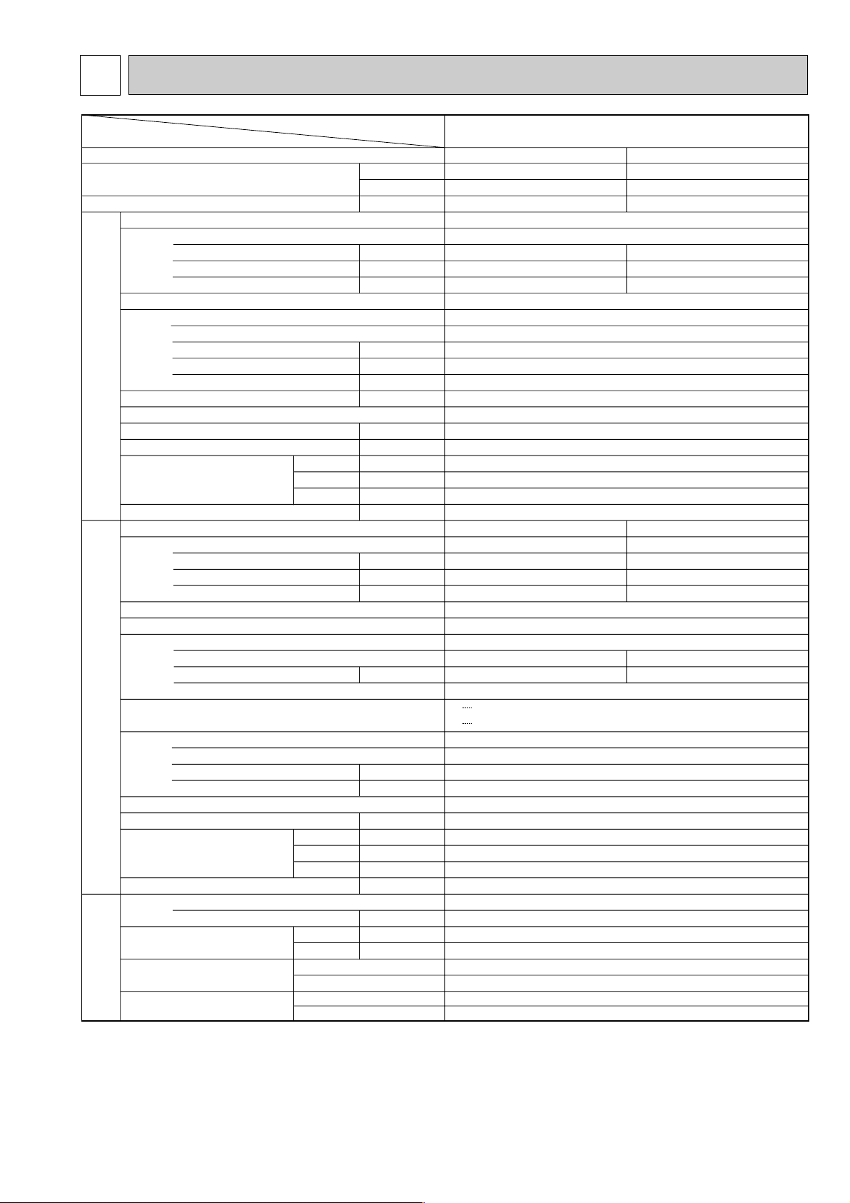
3 SPECIFICATIONS
Notes : Rating Conditions
(INDOOR) Cooling: 27 °CDB, 19 °CWB Heating: 20°CDB
(OUTDOOR) Cooling: 35 °CDB, 24 °CWB Heating: 7°CDB, 6°CWB
Item
Function
Service Ref.
PSH-3GJHA
1
PSH-3GJHA1
PUH-3VKA2.UK PUH-3YKA2.UK
W
Btu/h
kW
Cooling
7700
26300
3.31
Heating
8900 [11,000]
30,400 [37,500]
3.1 [5.20]
Capacity
Total input
Service Ref.
Power supply(phase,cycle,voltage)
External finish
Heat exchanger
Input
Running current
Starting current
Fan(drive) x No.
Fan motor output
Airflow(Low-High)
External static pressure
Booster heater
Operation control & Thermostat
Noise level(Low-High)
Cond. drain conn. O.D.
dB(A)
mm,(in.)
mm,(in.)
mm,(in.)
mm,(in.)
kg,(lbs)
W
D
H
Dimensions
Weight
Weight
Service Ref.
Power supply(phase,cycle,voltage)
Input (Cool/Heat)
Running current (Cool/Heat)
Starting current (Cool/Heat)
Model
Motor output
Starter type
External finish
Refrigerant control
Compressor
kW
Protection devices
Heat exchanger
Fan(drive) x No.
Fan motor output
Airflow
kW
m
3
/min,(CFM)
Defrost method
Noise level
Dimensions
W
D
H
dB(A)
mm,(in.)
mm,(in.)
mm,(in.)
kg,(lbs)
Refrigerant
Charge
Pipe size O.D.
Connection method
Between the indoor & outdoor units
REFRIGERANT
PIPING
OUTDOOR UNIT
INDOOR UNIT
Liquid
Gas
kg,(lbs)
mm,(in.)
mm,(in.)
Indoor side
Outdoor side
Height difference
Piping Iength
Single, 50Hz, 220-240V
3.15 / 2.94
13.82 / 12.89
54 / 58
3, 50Hz, 380-415V(4 Wires)
3.15 / 2.94
5.16 / 4.81
34 / 37
Munsell 0.70Y 8.59 / 0.97
Plate fin coil
Centrifugal(direct) x 1
0.03
14-17(494-600) / 15-18(530-635)
0(direct blow)
1.8 / 2.1
built-in
37-42 / 40-45
26(1)
600(23-5/8)
270(10-5/8)
1900(74-13/16)
45(99)
0.16
0.68
0.8
0.16 [2.26]
0.68 [9.43]
0.8 [9.6]
Munsell 5Y 7/1
Capillary tube
Hermetic
NH52YDA
2.4
NH52VND
2.2
Line start
Single, 50Hz, 220-240V
V Internal thermostat, HP switch
Y Reversed phase protector, thermal relay, thermal switch, HP switch
Plate fin coil
Propeller(direct) x 1
0.085
50 (1764)
Reverse cycle
52
870 (34-1/4)
295+24 (11-5/8 add 1 )
850 (33-7/16)
75 (165)
R-22
3.2 (7.0)
9.52 (3/8)
15.88 (5/8)
Flared
Flared
Max. 50m
MAx. 50m
kW
m
3
/min,(CFM)
Pa
kW
kW
A
A
kW
A
A
Page 6
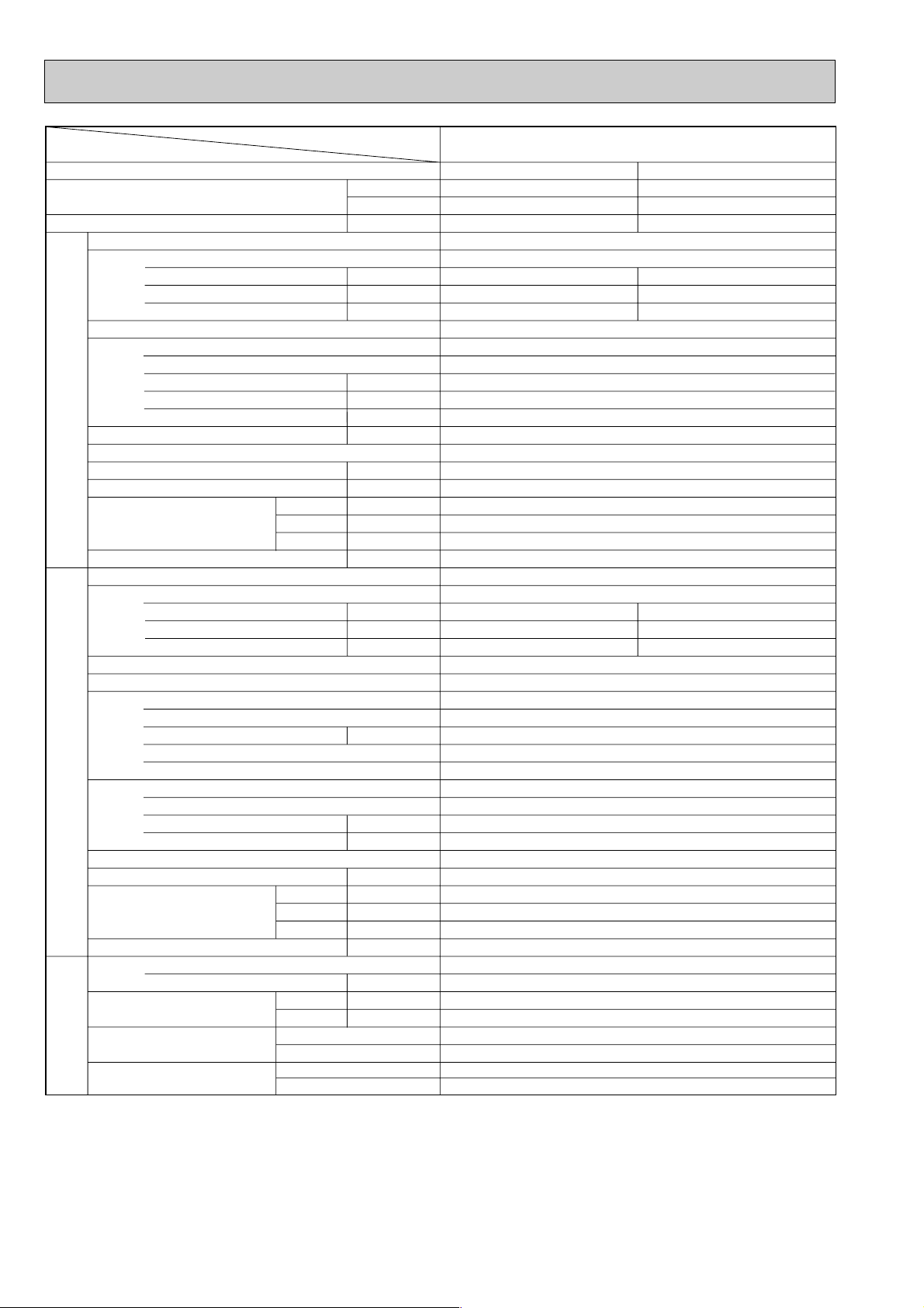
6
Item
Notes : Rating Conditions
(INDOOR) Cooling: 27 °CDB, 19 °CWB Heating: 20°CDB
(OUTDOOR) Cooling: 35 °CDB, 24 °CWB Heating: 7°CDB, 6°CWB
Function
Capacity
Total input
Service Ref.
Power supply(phase,cycle,voltage)
Input
Running current
Starting current
External finish
Heat exchanger
Fan(drive) x No.
Fan motor output
Airflow(Low-High)
External static pressure
Booster heater
INDOOR UNIT
Operation control & Thermostat
Noise level(Low-High)
Cond. drain conn. O.D.
W
Dimensions
D
H
Weight
Service Ref.
Power supply(phase,cycle,voltage)
Input
Running current
Starting current
External finish
Refrigerant control
Compressor
Model
Motor output
Stater type
Protection devices
Heat exchanger
OUTDOOR UNIT
Fan(drive) x No.
Fan motor output
Airflow
Defrost method
Noise level
W
Dimensions
D
H
Weight
Refrigerant
Charge
Pipe size O.D.
PIPING
Connection method
REFRIGERANT
Between the indoor & outdoor units
Liquid
Gas
Indoor side
Outdoor side
Height difference
Piping Iength
Service Ref.
W
Btu/h
kW
kW
A
A
kW
3
m
/min,(CFM)
Pa
kW
dB(A)
mm,(in.)
mm,(in.)
mm,(in.)
mm,(in.)
kg,(lbs)
kW
A
A
kW
kW
3
/min,(CFM)
m
dB(A)
mm,(in.)
mm,(in.)
mm,(in.)
kg,(lbs)
kg,(lbs)
mm,(in.)
mm,(in.)
PSH-4GJHSA
Cooling
10,200
34,800
3.46
1
Heating
10,850 [13,550]
37,000 [46,200]
3.45 [6.15]
PSH-4GJHSA1
Single, 50Hz, 220-240V
0.26
1.10
1.5
0.26 [2.96]
1.10 [12.35]
1.5 [12.8]
Munsell 0.70Y 8.59 / 0.97
Plate fin coil
Centrifugal(direct) x 1
0.07
22-28 / 24-31(776-988/847-1094)
0(direct blow)
2.3 / 2.7
built-in
42-47 / 43-48
26(1)
600(23-5/8)
350(13-3/4)
1900(74-13/16)
53(117)
PUH-4YKSA2.UK
3, 50Hz, 380-415V(4 Wires)
3.20
5.24
40
3.19
5.22
40
Munsell 5Y 7/1
Capillary tube
Hermetic
NH56YDA
2.7
Line start
Reversed phase protector, thermal relay, thermal switch, HP switch
Plate fin coil
Propeller(direct) x 2
0.065 + 0.065
95 (3350)
Reverse cycle
54
870 (34-1/4)
295+24 (11-5/8 add 1 )
1258 (49-1/2)
94 (207)
R-22
4.2 (9.3)
9.52 (3/8)
19.05 (3/4)
Flared
Flared
Max. 50m
Max. 50m
Page 7
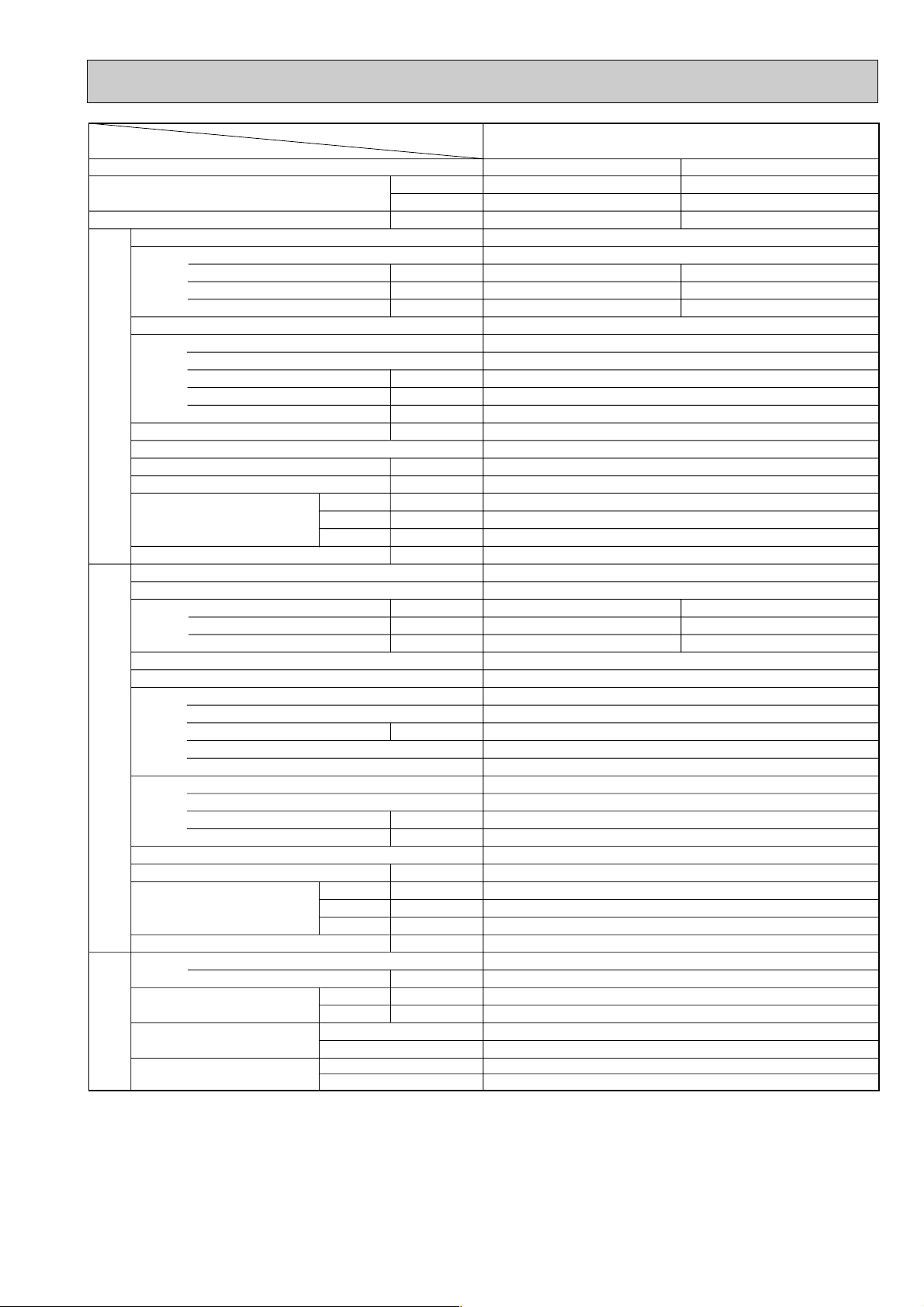
7
Notes : Rating Conditions
(INDOOR) Cooling: 27 °CDB, 19 °CWB Heating: 20°CDB
(OUTDOOR) Cooling: 35 °CDB, 24 °CWB Heating: 7°CDB, 6°CWB
Item
Function
Service Ref.
PSH-5GJHSA
1
PSH-5GJHSA1
PUH-5YKSA2.UK
W
Btu/h
kW
Cooling
12,500
42,700
4.51
Heating
13,700 [16,700]
46,700 [57,000]
4.46 [7.46]
Capacity
Total input
Service Ref.
Power supply(phase,cycle,voltage)
External finish
Heat exchanger
Input
Running current
Starting current
Fan(drive) x No.
Fan motor output
Airflow(Low-High)
External static pressure
Booster heater
Operation control & Thermostat
Noise level(Low-High)
Cond. drain conn. O.D.
dB(A)
mm,(in.)
mm,(in.)
mm,(in.)
mm,(in.)
kg,(lbs)
W
D
H
Dimensions
Weight
Weight
Service Ref.
Power supply(phase,cycle,voltage)
Input
Running current
Starting current
Model
Motor output
Stater type
External finish
Refrigerant control
Compressor
kW
Protection devices
Heat exchanger
Fan(drive) x No.
Fan motor output
Airflow
kW
m
3
/min,(CFM)
Defrost method
Noise level
Dimensions
W
D
H
dB(A)
mm,(in.)
mm,(in.)
mm,(in.)
kg, (lbs)
Refrigerant
Charge
Pipe size O.D.
Connection method
Between the indoor & outdoor units
REFRIGERANT
PIPING
OUTDOOR UNIT
INDOOR UNIT
Liquid
Gas
kg,(lbs)
mm,(in.)
mm,(in.)
Indoor side
Outdoor side
Height difference
Piping Iength
4.21
6.89
53
4.16
6.81
53
Munsell 0.70Y 8.59 / 0.97
Plate fin coil
Centrifugal(direct) x 1
0.110
23-31 (812-1094) / 26-33(918-1165)
0(direct blow)
2.5 / 3.0
built-in
43-49 / 46-51
26(1)
600(23-5/8)
350(13-3/4)
1900(74-13/16)
53(117)
0.30
1.26
1.5 / 1.5
0.30 [3.30]
1.26 [13.76]
1.5 [14.0]
Munsell 5Y 7/1
Capillary tube
Hermetic
ZR61KC-TFD
3.5
Line start
Single, 50Hz, 220-240V
Reversed phase protector, Inner thermostat, Thermal switch, HP switch
Plate fin coil
Propeller(direct) x 2
0.085 + 0.085
95 (3350)
Reverse cycle
55
970 (38-3/16)
345+24 (13-9/16 add 1 )
1258 (49-1/2)
114 (251)
R-22
5.4 (11.9)
9.52 (3/8)
19.05 (3/4)
Flared
Flared
Max. 50m
Max. 50m
3, 50Hz, 380-415V(4 Wires)
kW
m
3
/min,(CFM)
Pa
kW
kW
A
A
kW
A
A
Page 8
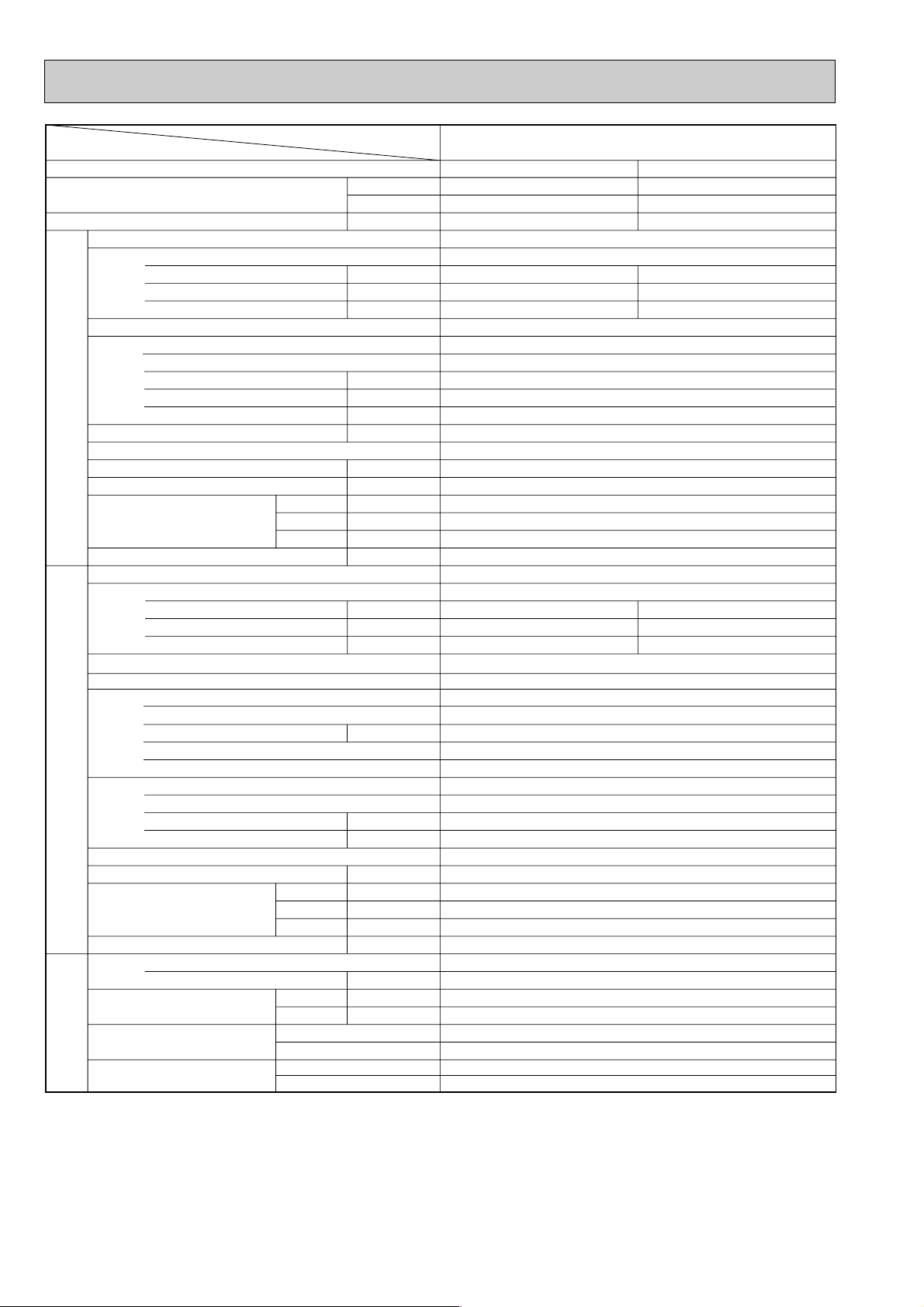
8
Notes : Rating Conditions
(INDOOR) Cooling : 27 °C DB, 19 °C WB Heating : 20 °C WB
(OUTDOOR) Cooling : 35 °C DB, 24 °C WB Heating : 7 °C DB,6 °C WB
Item
Function
Service Ref.
PSH-6GJHSA
1
PSH-6GJHSA1
PUH-6YKSA2.UK
W
Btu/h
kW
Cooling
14200
48450
5.11
Heating
16000 [19000]
54600 [64800]
4.96 [7.96]
Capacity
Total input
Service Ref.
Power supply(phase,cycle,voltage)
External finish
Heat exchanger
Input
Running current
Starting current
Fan(drive) x No.
Fan motor output
Airflow(Low-High)
External static pressure
Booster heater
Operation control & Thermostat
Noise level(Low-High)
Cond. drain conn. O.D.
dB(A)
mm,(in.)
mm,(in.)
mm,(in.)
mm,(in.)
kg,(lbs)
W
D
H
Dimensions
Weight
Weight
Service Ref.
Power supply(phase,cycle,voltage)
Input
Running current
Starting current
Model
Motor output
Stater type
External finish
Refrigerant control
Compressor
kW
Protection devices
Heat exchanger
Fan(drive) x No.
Fan motor output
Airflow
kW
m
3
/min,(CFM)
Defrost method
Noise level
Dimensions
W
D
H
dB(A)
mm,(in.)
mm,(in.)
mm,(in.)
kg,(lbs)
Refrigerant
Charge
Pipe size O.D.
Connection method
Between the indoor & outdoor units
REFRIGERANT
PIPING
OUTDOOR UNIT
INDOOR UNIT
Liquid
Gas
kg,(lbs)
mm,(in.)
mm,(in.)
Indoor side
Outdoor side
Height difference
Piping Iength
4.73
7.74
58
4.58
7.50
58
Munsell 0.70Y 8.59 / 0.97
Plate fin coil
Centrifugal(direct) x 1
0.12
25-32 (882-1130) / 27-35(953-1236)
0(direct blow)
2.5 / 3.0
built-in
45-50 / 47-52
26(1)
600(23-5/8)
350(13-3/4)
1900(74-13/16)
53(121)
0.38
1.62
2.1
0.38 [3.38]
1.62 [14.12]
2.1 [14.6]
Munsell 5Y 7/1
Capillary tube
Hermetic
ZR-68KC-TFD
4.0
Line start
Single, 50Hz, 220-240V
Reversed phase protector, Inner thermostat, thermal switch, HP switch
Plate fin coil
Propeller(direct) x 2
0.10 + 0.10
100 (3530)
Reverse cycle
56
970 (38-3/16)
345+24 (13-9/16 add 1 )
1258 (49-1/2)
117 (258)
R-22
5.0 (11.0)
9.52 (3/8)
19.05 (3/4)
Flared
Flared
Max. 50m
Max. 50m
3, 50Hz, 380-415V(4 Wires)
kW
m
3
/min,(CFM)
Pa
kW
kW
A
A
kW
A
A
Page 9

9
4 DATA
1. PERFORMANCE DATA
1) COOLING CAPACITY
Note CA :Capacity (W)
P.C.:Power consumption (kW)
Cooling capacity correction factors
1.4
1.2
1.0
0.8
0.6
1.4
1.2
1.0
0.8
0.6
0.4
-5 5 15 25 35 46
OUTDOOR DB (:)
INDOOR WB (:)
INDOOR WB (:)
CAPACITY(RATIO)TOTAL INPUT(RATIO)
22
20
18
16
22
20
18
16
Service Ref.
PSH-3GJHA
1
PSH-4GJHSA1
PSH-5GJHSA1
PSH-6GJHSA1
Indoor
intake air
WB$C
16
18
20
22
16
18
20
22
16
18
20
22
16
18
20
22
20 25 30 35 40 45
CA
7,768
8,271
8,779
9,293
10,290
10,956
11,630
12,310
12,611
13,427
14,252
15,086
14,326
15,253
16,190
17,138
P.C.
2.65
2.71
2.76
2.81
2.77
2.83
2.88
2.94
3.61
3.69
3.76
3.83
4.10
4.18
4.26
4.34
CA
7,555
8,053
8,573
9,115
10,008
10,668
11,356
12,074
12,265
13,073
13,917
14,797
13,933
14,851
15,810
16,809
P.C.
2.77
2.82
2.88
2.94
2.89
2.95
3.01
3.07
3.77
3.85
3.92
4.00
4.27
4.36
4.44
4.53
CA
6,983
7,452
7,948
8,470
9,250
9,872
10,528
11,220
11,336
12,098
12,902
13,750
12,878
13,743
14,657
15,621
P.C.
3.41
3.49
3.59
3.69
3.56
3.65
3.75
3.86
4.64
4.76
4.89
5.02
5.26
5.39
5.54
5.69
CA
7,278
7,760
8,267
8,799
9,641
10,279
10,951
11,656
11,815
12,597
13,420
14,284
13,421
14,310
15,246
16,227
P.C.
2.98
3.05
3.11
3.18
3.11
3.18
3.25
3.32
4.06
4.15
4.24
4.33
4.60
4.70
4.81
4.91
P.C.
3.19
3.27
3.35
3.43
3.34
3.42
3.50
3.59
4.35
4.46
4.56
4.67
4.93
5.05
5.17
5.30
CA
6,671
7,130
7,616
8,128
8,837
9,445
10,088
10,767
10,858
11,590
12,365
13,184
12,334
13,166
14,047
14,977
CA
6,342
6,793
7,270
7,773
8,401
8,999
9,631
10,297
10,332
11,053
11,814
12,617
11,737
12,556
13,421
14,333
P.C.
3.62
3.72
3.83
3.96
3.79
3.89
4.00
4.14
4.94
5.06
5.22
5.39
5.59
5.74
5.91
6.10
outdoor intake air DB$C
Service Ref.
PSH-3GJHA1
PSH-4GJHSA1
PSH-5GJHSA1
PSH-6GJHSA1
Refrigerant piping length(one way)
5m
1.00
1.00
1.00
1.00
10m
0.981
0.989
0.981
0.975
15m
0.968
0.980
0.968
0.955
20m
0.952
0.970
0.952
0.935
25m
0.940
0.960
0.918
0.918
30m
0.925
0.950
0.925
0.900
35m
0.913
0.940
0.913
0.884
40m
0.900
0.930
0.900
0.869
45m
0.886
0.920
0.886
0.855
50m
0.874
0.910
0.874
0.840
Page 10

2) HEATING CAPACITY
Note CA :Capacity (W)
P.C.:Power consumption (kW)
Heating capacity correction factors
10
Service Ref.
PSH-3GJHA
PSH-4GJHSA1
PSH-5GJHSA1
PSH-6GJHSA1
1
Indoor
intake air
WB$C
15
20
25
15
20
25
15
20
25
15
20
25
6,095
5,836
5,609
7,430
7,115
6,837
9,382
8,983
8,633
10,957
10,492
10,083
Service Ref.
PSH-3GJHA
PSH-4GJHSA1
PSH-5GJHSA1
PSH-6GJHSA1
5m
1
1.00
1.00
1.00
1.00
10m
1.00
1.00
1.00
1.00
CA
-10
-5
P.C.
P.C.
2.11
2.28
2.42
2.35
2.54
2.69
3.04
3.28
3.48
3.38
3.65
3.87
CA
6,985
6,711
6,438
8,516
8,181
7,849
10,753
10,330
9,911
12,558
12,065
11,575
Refrigerant piping length(one way)
15m
1.00
1.00
1.00
1.00
2.34
2.52
2.68
2.60
2.80
2.99
3.36
3.62
3.86
3.74
4.03
4.30
20m
1.00
1.00
1.00
1.00
Outdoor intake air WB$C
05
30m
1.00
1.00
1.00
1.00
CA
9,023
8,686
8,365
10,999
10,589
10,197
13,889
13,371
12,876
16,220
15,616
15,037
35m
0.998
0.988
0.988
0.988
CA
7,962
7,661
7,357
9,706
9,340
8,969
12,256
11,793
11,325
14,313
13,773
13,227
25m
1.00
1.00
1.00
1.00
P.C.
2.57
2.77
2.97
2.86
3.09
3.30
3.70
3.99
4.27
4.12
4.44
4.74
P.C.
2.83
3.04
3.26
3.14
3.39
3.63
4.06
4.38
4.69
4.52
4.87
5.22
10 15
P.C.
CA
10,167
9,784
9,459
12,394
11,928
11,532
15,650
15,061
14,561
18,277
17,590
17,006
0.995
0.955
0.955
0.955
3.09
3.33
3.57
3.44
3.70
3.97
4.45
4.79
5.13
4.94
5.33
5.71
40m
45m
0.993
0.993
0.993
0.993
CA
11,392
10,955
10,641
13,888
13,355
12,973
17,536
16,864
16,381
20,480
19,695
19,131
P.C.
3.37
3.63
3.89
3.75
4.04
4.33
4.85
5.22
5.60
5.39
5.80
6.23
50m
0.990
0.990
0.990
0.990
1.4
1.2
1.0
0.8
CAPACITY(RATIO)
0.6
1.4
1.2
1.0
0.8
TOTAL INPUT(RATIO)
0.6
0.4
-12-10 -5 0 5 10 15
OUTDOOR WB (:)
15
20
25
INDOOR DB (:)
INDOOR DB (:)
25
20
15
Page 11

11
2. ELECTRICAL DATA
Indoor ……220V 50Hz 1phase
Outdoor … 220V 50Hz 1phase / 380V 50Hz 3phase
Indoor ……230V 50Hz 1phase
Outdoor … 230V 50Hz 1phase / 380V 50Hz 3phase
Indoor ……240V 50Hz
Outdoor … 240V 50Hz 1phase / 415V 50Hz 3phase
Service Ref.
Mode
Capacity(W)
Total input(kW)
Input(kW)
Current(A)
Starting current(A)
Input(kW)
Current(A)
Starting current(A)
Indoor
unit
Outdoor
unit
PSH-4GJHSA1 / PUH-4YKSA2.UK PSH-5GJHSA1 / PUH-5YKSA2.UK PSH-6GJHSA1 / PUH-6YKSA2.UK
Cool HeatCool
7,500
3.27
0.14
0.64
0.8
3.13
14.67/5.23
54 / 34
PSH-3GJHA1 /
PUH-3VKA2.UK
PUH-3YKA
2
.UK
Heat
8,800
[10,600]
3.06
[4.86]
0.14
[1.94]
0.64
[8.82]
0.8
2.92
13.68/4.88
54 / 34
Cool
10,100
3.39
0.22
1.02
1.5
3.17
5.29
37
Heat
10,650
[12,950]
3.38
[5.68]
0.22
[2.52]
1.02
[11.47]
1.5
3.16
5.28
37
12,200
4.45
0.26
1.20
1.5
4.19
7.32
49
13,400
[15,900]
4.39
[6.89]
0.26
[2.76]
1.20
[12.56]
1.5
4.13
7.21
49
Cool
14,000
4.98
0.34
1.56
2.1
4.64
8.10
68
Heat
15,600
[18,100]
4.90
[7.40]
0.34
[7.40]
1.56
[12.92]
2.1
4.56
7.96
68
Service Ref.
Mode
Capacity(W)
Total input(kW)
Input(kW)
Current(A)
Starting current(A)
Input(kW)
Current(A)
Starting current(A)
Indoor
unit
Outdoor
unit
PSH-4GJHSA1 / PUH-4YKSA2.UK PSH-5GJHSA1 / PUH-5YKSA2.UK
PSH-6GJHSA1 / PUH-6YKSA2 .UK
PSH-3GJHA1 /
PUH-3VKA
2.UK
PUH-3YKA2.UK
Cool
7,600
3.29
0.15
0.66
0.8
3.14
14,22/ 5.21
56 / 36
Heat
8,850
[10,750]
3.08
[4.98]
0.15
[2.05]
0.66
[8.92]
0.8
2.93
13.27/4.86
56 / 36
Cool
10,150
3.43
0.24
1.06
1.5
3.19
5.23
39
Heat
10,750
[13,250]
3.42
[5.92]
0.24
[2.74]
1.06
[11.93]
1.5
3.18
5.22
39
Cool
12,350
4.48
0.28
1.23
1.5
4.20
7.05
51
Heat
13,550
[16,250]
4.43
[7.13]
0.28
[2.98]
1.23
[12.97]
1.5
4.15
6.97
51
Cool
14,100
5.05
0.36
1.59
2.1
4.69
7.87
71
Heat
15,800
[18,500]
4.93
[7.63]
0.36
[3.06]
1.59
[13.33]
2.1
4.57
7.67
71
Service Ref.
Mode
Capacity(W)
Total input(kW)
Input(kW)
Current(A)
Starting current(A)
Input(kW)
Current(A)
Starting current(A)
Indoor
unit
Outdoor
unit
PSH-4GJHSA1 / PUH-4YKSA2.UK PSH-5GJHSA1 / PUH-5YKSA2.UK PSH-6GJHSA1 / PUH-6YKSA2.UK
PSH-3GJHA1 /
PUH-3VKA
2.UK
PUH-3YKA2.UK
Cool
7,700
3.31
0.16
0.68
0.8
3.15
13.82/ 5.16
58 / 37
Heat
8,900
[11,000]
3.10
[5.20]
0.16
[2.26]
0.68
[9.43]
0.8
2.94
12.89/4.81
58 / 37
Cool
10,200
3.46
0.26
1.10
1.5
3.20
5.24
40
Heat
10,850
[13,550]
3.45
[6.15]
0.26
[2.96]
1.10
[12.35]
1.5
3.19
5.22
40
Cool
12,500
4.51
0.30
1.26
1.5
4.21
6.89
53
Heat
13,700
[16,700]
4.46
[7.46]
0.30
[3.30]
1.26
[13.76]
1.5
4.16
6.81
53
Cool
14,200
5.11
0.38
1.62
2.1
4.73
7.74
74
Heat
16,000
[19,000]
4.96
[7.96]
0.38
[3.38]
1.62
[14.12]
2.1
4.58
7.50
74
Page 12

12
3. STANDARD OPERATION DATA
4. REFILLING REFRIGERANT CHARGE (R-22 : kg)
5. OUTLET AIR SPEED AND COVERAGE RANGE
Service Ref.
PSH-3GJHA
1
PUH-3VKA2.UK
PUH-3YKA
2.UK
PUH-4YKSA
2.UK
PUH-5YKSA
2.UK
PUH- 6YKSA
2.UK
PSH-4GJHSA
1
PSH-5GJHSA1
PSH-6GJHSA1
FACTORY
CHARGED
UP TO
3.2kg
3.2kg
4.2kg
5.4kg
5.0kg
Refrigerant piping length(one way)
5m
2.5
2.5
3.5
4.7
4.3
10m
2.7
2.7
3.6
4.8
4.4
15m
2.8
2.8
3.8
5.0
4.6
20m
2.9
2.9
3.9
5.1
4.7
25m
3.1
3.1
4.1
5.3
4.9
30m
3.2
3.2
4.2
5.4
5.0
35m
3.3
3.3
4.4
5.6
5.2
40m
3.4
3.4
4.5
5.7
5.3
45m
3.6
3.6
4.6
5.9
5.5
50m
3.7
3.7
4.8
6.0
5.6
Air flow
Air speed
Coverage range
m3/min
m/sec.
m
PSH-3GJHA1 PSH-4GJHSA1 PSH-5GJHSA1 PSH-6GJHSA1
18
2.8
8.9
(29.2)
31
4.7
14.8
(48.5)
33
5.0
16.0
(52.5)
35
5.4
16.9
(55.4)
The unit of pressure has been changed to Mpa based on the international SI system .
The conversion factor is : 1(Mpa.G)= 10.2(kgf/cm
2
.
G)
PSH-3GJHA
1,50
240
1/3, 50
240 / 415
2.1
5.7
5
27
19
35
24
PUH-3VKA2.UK
PUH-3YKA2.UK
Heating
8900
3.10
[5.20]
1
0.68
[9.43]
12.89 / 4.81
1.91
(19.5)
0.35
(3.57)
85.6
5
20
15.5
46.0
7
6
PSH-4GJHSA1/PUH-4YKSA2.UK
Cooling
10200
3.46
PSH-4GJHSA
Heating
10850
3.45
[6.15]
1
1,50
240
1.10
PUH-4YKSA
1.10
[12.35]
2.UK
3,50
415
5.24
1.85
(18.9)
0.52
(5.3)
79.4
5.22
1.72
(17.5)
0.37
(3.77)
77.4
48.7
7.2
5
27
19
13.6
35
24
5
20
15.5
38.8
7
6
0.72
0.09
PSH-5GJHSA1 / PUH-5YKSA2.UK PSH-6GJHSA1 / PUH-6YKSA2.UK
Cooling
12500
4.51
PSH-5GJHSA
1.26
PUH-5YKSA
6.89
1.87
(19.1)
0.47
(4.79)
71.0
49.4
11.2
5
27
19
13.5
35
24
0.74
0.13
Mode
Total
Service Ref.
Capacity
Input
W
kW
PSH-3GJHA1 /
Cooling
7700
3.31
Indoor unit Service Ref.
Phase, Hz
Volts
Amperes
Outdoor unit Service Ref.
Phase, Hz
Electrical cricuitRefrigerant circuit
0.68
PUH-3VKA2.UK, PUH-3YKA2.UK
Volts
Amperes
Discharge pressure
Suction pressure
Discahrge temperature
Condensing temperature
Suction temperature
Ref. pipe length
Intake air temperature
Mpa.G
(kgf/cm
Mpa.G
(kgf/cm
$C
$C
$C
m
DB$C
13.82 / 5.16
2
.
G)
2
.
G)
(21.4)
0.46
(4.69)
91.4
53.5
WB$C
Indoor side
Discharge air temperature
DB$C
12.2
DB$C
Intake air temperature
side
Outdoor
SHF
BF
WB$C
0.72
0.09
1,50
240
3,50
415
Heating
13700
4.46
[7.46]
1
1.26
[13.76]
2.UK
6.81
1.82
(18.6)
0.36
(3.67)
72.9
5
20
15.5
42.2
7
6
Cooling
14200
5.11
PSH-6GJHSA
1.62
PUH-6YKSA
7.74
1.87
(19.1)
0.44
(4.49)
71.2
49.2
3.3
5
27
19
11.5
35
24
0.69
0.12
1,50
240
3,50
415
Heating
16000
4.96
[7.96]
1
1.62
[14.12]
2.UK
7.50
1.82
(18.6)
0.37
(3.77)
72.5
-1.3-1.2-0.8-1.6
5
20
15.5
48.7
7
6
Page 13

13
5 OUTLINES AND DIMENSIONS
1. INDOOR UNIT
PSH-3GJHA
1
Unit:mm
277
Knock out hole
for bottom fixing
160
20
5 or more
300 or more
2
1
Front 1,000 or more
100 or more 100 or more
40 66
175
90
Knock out hole for
under-piping(120 70 oval)
95
218
Liquid pipe [9.52(3/8F)
95
Electrical parts box
46122
1. Service access allows for
insertion of screw driver.
2. Adjustable
186
Drain pipe
Gas pipe [19.05(5/8F)
47
590
480
110
105
Knock out hole for piping and wiring
(140 80 oval)
20
132
Knock out hole
for branch duct
240
130
100
125
340
370
Metal fixture
520
100
Rear side
55143
270
250
40
50260
against overturning
260
240
Front side
Knock out hole
for under-piping
130130
Terminal block
for control
766
130 71
Terminal block
for power supply
1900
608
767
714 123
115
50
70
216
Knock out hole for
wiring.[27
(Provided on both sides)
180
235
Knock out hole for refrigerant and drainage.
90 60 oval (Provided on both sides)
530
600
Rear side
10
3838
15
111
Front side
2010
controller
82730
Page 14

14
PSH-4GJHSA1
PSH-5GJHSA1
PSH-6GJHSA1
125
240
Front side
Metal fixture
against overturning
controller
Rear side
Front side
Rear side
Knock out hole
for branch duct
Knock out hole
for bottom fixing
Knock out hole
for under-piping
Knock out hole for
under-piping(120 70 oval)
100
10
3838
50260
130130
766
1900
608
50
115
714 123
767
110
480
590
216
40
82730
2010
111
15
130
132
277
120
20
218
255
140
77
201
120
340
370
520
260
240
130 71
530
600
350
330
70
260
315
Knock out hole for
wiring.[27 (Provided on both sides)
Knock out hole for refrigerant and drainage.
90 60 oval (Provided on both sides)
Knock out hole for piping and wiring
(140 80 oval)
20
105
Terminal block
for control
Electrical parts box
Liquid pipe [9.52(3/8F)
1. Service access allows for
insertion of screw driver.
2. Adjustable
Gas pipe [19.05(5/8F)
Drain pipe
Terminal block
for power supply
95
46122
47
95
40 66
261
100 or more 100 or more
2
5 or more
1
300 or more
Front 1,000 or more
Unit:mm
Page 15

15
6 WIRING DIAGRAM
NOTES :
1. Since the indoor transformer (T) is connected with 220V power, if 230,240V power is used. Change the wiring connection showing fig : w1.
fig : w1
When power supply is
2. Since the outdoor side electric wiring may change be sure to check the outdoor unit electric wiring during servicing.
3. Indoor and outdoor connecting wires are made with polarities, make wiring matching terminal.
4. Symbols used in circuit diagram above are. :connector :Terminal block
5. Emergency operation
If remote controller of microcomputer fails but there is no other trouble, emergency operation is possible by setting dip switch (SW3<I.B>) on the indoor
controller board.
[Check items]
(1) Compressor and fan.
(2) Check the trouble position using self diagnostic function. If the result of self diagnosis indicates protective device such as freeze protection is functioning,
emergency operation is not possible unless the cause is removed.
Emergency operation will be continuous operation mode due to power ON/OFF (ON/OFF with remote controller is not possible).
[Emergency operation procedure]
(1) Set the dip switch (SW3<I.B>) on the indoor controller board to 1 • 2 on and 3 off for cooling, and 1 • 2 • 3 on for heating.
(2) Turn on outdoor unit side circuit breaker, and then indoor unit side circuit breaker in this order.
(3) During emergency operation, the indoor fan runs on high speed but swing louver remains stop.
(4) Thermostat will not function. Cold air blows out for defrosting during heating, thus do not operate defrosting for a long time.
(5) Emergency cooling should be limited to 10 hours maximum (the indoor unit heat exchanger may freeze.)
TWIN-1TWIN-2
CN2A
CN2B
OFF
ON
GRN/YLW
26H
88H
N
L
I.B
TB2
TO OUTDOOR UNIT
CONNECTING WIRES
DC12V(polar)
321
T
ML
X6 X5 X4
X6 X5 X4
ZNR
FUSE1
X2
X2
FUSE2
C
MF
CNR120
LD7LD8
SW7
SW6
SW5
SW8
SW4
SW3
SW2
SW1
LD12
LD11
LD6
LD10
LD5
LD4
LD9
LD3
LD1
LD24
LD23
LD22
LD21
LD20
LD19
LD18
LD17
LD16
LD15
LD14
LD13
CN31
HEATER
123
CN2
TIMER
12345
CN50
DRAIN
CN20
INTAKE
12
CN21
PIPE
1
12
L.TEST
CN28
CN120
TO.RC
OUTDOOR
CN30
123
TRANS
CN4T
1234
CNT
TRANS
31
CND
POWER
31
CNL
LOUVER
317531
1 2 3
SW1
1 2 3 4
MULTIPLE
CN51
RT1
RT2
12
1 2 3
OFF
ON
SW3
SW2
FAN1
GRN/YLW
RED
FS1
YLW
ORN
RED
10.6VAC
14.5VAC
WHT
220V
230V
12345
YLW
RED
BG79N699H01
R.B
H
TB1
ORN
RED
YLW
YLW
BRN
ORN
YLW
YLW
RED
RED
WHT
RED
BLU
BRN
FS2
BRN
BRN
RED
RED
240V
BLU
BRN
YLW
YLW
WHT
YLW
BLU
BLK
88H
3
5
6
POWER SUPPLY
~(1 PHASE)
AC220Å|240V 50Hz
AC220V 60Hz
1
6
12
PSH-3GJHA1 / PSH-4GJHSA1 / PSH-5GJHSA1 / PSH-6GJHSA1
SYMBOL
C
CN2<I.B>
CN2A<I.B>
CN2B<I.B>
CN28<I.B>
CN51<I.B>
FUSE1,2<I.B>
FS1,2
H
I.B
LD1<R.B>
LD3<R.B>
LD4<R.B>
LD5<R.B>
LD6<R.B>
LD7<R.B>
LD8<R.B>
NAME
FAN MOTOR CAPACITOR
TIMER ADAPTOR CONNECTOR
TRANSMISSION WIRES No.1 CONNECTOR
TRANSMISSION WIRES No.2 CONNECTOR
TIME SHORTENING CONNECTOR
MULTIPLE CONNECTOR
FUSE<6.3A>
THERMAL FUSE (110˚C 6A)
HEATER
INDOOR CONTROLLER BOARD
RUN INDICATOR LED
COOLING INDICATOR LED
HEATING INDICATOR LED
FAN HIGH INDICATOR LED
LOUVER ON INDICATOR LED
TEMPERATURE MODE TEMPERATURE LED
TIMER MODE INDICATOR LED
SYMBOL
LD9<R.B>
LD10<R.B>
LD11<R.B>
LD12<R.B>
LD13~24
<R.B>
MF
ML
R.B
SW1<I.B>
SW2<I.B>
SW3<I.B>
SW1<R.B>
SYMBOL
SW2<R.B>
SW3<R.B>
SW4<R.B>
SW5<R.B>
SW6<R.B>
SW7<R.B>
SW8<R.B>
T
TB1
X2<I.B>
X4,X5,X6<I.B>
ZNR
26H
88H
NAME
DRY INDICATOR LED
FAN LOW INDICATOR LED
OFF TIMER INDICATOR LED
ON TIMER INDICATOR LED
TEMPERATURE/TIMER
REMAINING TIME INDICATORLED
INDOOR FUN MOTOR
LOUVER MOTOR
CONTROLLER BOARD
ROOM TEMPERATURE THERMISTOR
(0˚C/15k", 25˚C/5.4k" DETECT)
INDOOR COIL THERMISTOR
(0˚C/15k", 25˚C/5.4k" DETECT)
FUNCTION SELECTOR
UNIT SELECTOR
EMERGENCY OPERATION SWITCH
ON/OFF SWITCH
NAME
OPERATION MODE SELECTOR
FAN SPEED HIGH/LOW SELECTOR
LOUVER ON/OFF SWITCH
DISPLAY SELECTOR
RAISES SET TEMPERATURE/TIMER UP SWITCH
LOWERS SET TEMPERATURE/TIMER DOWN SWITCH
TIMER MODE SELECTOR
TRANSFORMER
POWER SUPPLY TERMINAL BLOCK
INDOOR/OUTDOOR
CONNECTING WIRE TERMINAL BLOCK
LOUVER MOTOR RELAY
INDOOR FAN RELAY
VARISTOR
HEATER THERMAL SWITCH
HEATER CONTACTOR
RT1
RT2
TB2
230V
240V
220V
230V
YELLOW
ORANGE
RED
240V
Page 16

16
7 REFRIGERANT SYSTEM DIAGRAM
PSH-3GJHA1 / PUH-3VKA2.UK
PSH-4GJHSA
1 / PUH-4YKSA2.UK
PSH-5GJHSA
1 / PUH-5YKSA2.UK
PSH-6GJHSA
1 / PUH-6YKSA2.UK
Indoor
heat
exchanger
Distributor
with
strainer
PSH-3GJHA
1············O.D.4.0 I.D.2.0-R500
Thermistor
RT2
Restrictor
valve
Flexible tube
Flared
connection
Refrigerant pipe
(option)
15.88mm ([5/8")
(with heat insulator)
Refrigerant pipe
(option)
9.52mm ([3/8")
(with heat insulator)
Ball valve
4-way valve
Oil separator
Service
port
High pressure
control switch
Outdoor heat exchanger
Capillary
tube
Thermistor
TH
Capillary
tube
Compressor
Bypass
valve
Restrictor
valve
Accumulator
Ball valve
(with service port)
Strainer
Strainer
Strainer
Service
port
PUH-3VK2, YK3··············O.D.4.0 I.D.2.4- R1,070
PUH-3VKA, YKA
Refrigerant flow in cooling
Refrigerant flow in heating
R.V coil
heating ON
cooling OFF
High pressure
protect switch
Indoor
heat
exchanger
Thermistor
RT2
Distributor
with
strainer
PSH-4GJHSA
Indoor
heat
exchanger
Thermistor
RT2
Distributor
with
strainer
PSH-5GJHSA
PSH-6GJHSA1··········O.D.4.0 I.D.3.0-R1,200
Strainer
Restrictor
valve
Capillary
tube
1··········O.D.4.0 I.D.2.0-R400
Strainer
Restrictor
valve
Capillary
tube
1··········O.D.4.0 I.D.2.4-R350
Refrigerant pipe
(option)
19.05mm ([3/4")
(with heat insulator)
Flexible tube
Flared
connection
Flexible tube
Refrigerant pipe
(option)
9.52mm ([3/8)
(with heat insulation)
Refrigerant pipe
(option)
19.05mm ([3/4˚)
(with heat insulator)
Flexible tube
Flared
connection
Flexible tube
Refrigerant pipe
(option)
9.52mm ([3/8)
(with heat insulator)
Strainer
Service
port
Accumulator
Ball valve
Strainer
Service
port
4-way valve
Accumulator
Ball valve
Ball valve
(with service port)
Ball valve
(with service port)
Oil separator
Oil separator
4-way valve
High pressure
control switch
Service
port
Compressor
High pressure
protect switch
High pressure
control switch
Service
port
Compressor
High pressure
protect switch
PUH-5YKSA··············(O.D.4.0 I.D.2.4- R840) 2
PUH-6YKSA·················(O.D.4.0 I.D.2.4- R1,200) 2
Outdoor heat exchanger
Bypass
valve
Strainer
THERMAL
SWITCH
Outdoor heat exchanger
Bypass
valve
Capillary tube
Strainer
(O.D.3.2 I.D.2.0-R820) 2
Thermistor
TH3
Restrictor
valve
Capillary
tube
Thermistor
TH
Restrictor
valve
Capillary
tube
Page 17

17
8 DISASSEMBLY PROCEDURE
OPERATING PROCEDURE PHOTOS
1. Removing the intake grill
(1) Remove the screw at the center of the knob of
the intake grill.
(2) Pull the knob of the intake grill toward you.
(3) Remove the 2 hangers.
(4) Lift the intake grill to remove.
2. Removing the indoor controller board
(1) Remove the intake grill.
(2) Remove the 3 screws of the electrical parts
cover and remove the electrical parts cover.
(3) Disconnect the fan motor connector and the
connectors on the indoor controller board.
(4) Unhook the catch of the controller case by
opening, and remove the indoor controller board.
3. Removing the room temperature thermistor
(1) Remove the intake grill.
(2) Remove the electrical parts cover.
(3) Take out the room temperature thermistor with
the holder. (See Photo 3.)
(4) Pull the room temperature thermistor out of the
holder.
(5) Disconnect the red connector CN20 on the
indoor controller board.
4. Removing the indoor fan and the indoor fan
motor
(1) Remove the intake grill.
(2) Turn the bell mouth clockwise to remove.
(3) Remove the fan nut and the washer.
(4) Pull out the indoor fan. (See Photo 2.)
(5) Remove the 2 screws of the wiring cover and
remove the wiring cover.
(6) Remove the 4 fan-motor nuts and remove the
indoor fan motor.
(7) Remove the electrical parts cover.
(8) Disconnect the fan motor connector.
(See Photo 3.)
Photo 1
Photo 2
Photo 3
Photo 4
Knob
Hanger
Intake grill
Capacitor
Fan motor connector Indoor controller board
Room
temperature
thermistor
Relay
Transformer
Controller case
Catches
Nuts
Indoor fan
motor
Screws
Wiring cover
Electrical parts box
*This unit is PSH-GJH(S)A
Screws
Bell mouth
Indoor fan
Fan nut & washer
Electrical
parts cover
*
Page 18

18
OPERATING PROCEDURE PHOTOS
5. Removing the front panel
(1) Remove the intake grill.
(2) Remove the 2 screws at the lower part of the
front panel.
(3) Pull the front panel down to remove.
(4) Disconnect the blue connector of the controller.
6. Removing the louver motor
(1) Remove the intake grill.
(2) Remove the front panel.
(3) Remove the 5 screws of the swing louver and
remove the swing louver.
(4) Remove the 2 screws of the louver motor and
remove the louver motor.
(5) Remove the electrical parts cover.
(6) Disconnect the terminal “VANE” on the indoor
controller board.
7. Removing the indoor coil thermistor
(1) Remove the intake grill.
(2) Remove the front panel.
(3) Remove the 10 screws of the insulation panel
and remove the insulation panel .
(4) Remove the swing louver.
(5) Remove the screw of the piping cover and
remove the piping cover.
(6) Remove the indoor coil thermistor from the
holder on the copper pipe.
(7) Remove the electrical parts cover.
(8) Disconnect the connector CN21 on the indoor
controller board.
Photo 5
Photo 6
Photo 7
Photo 8
Photo 9
Swing louver
Controller
Screws
Top panel
Front panel
Swing
louver
screws
Screws
Swing
louver
Swing louver
<Back view of swing louver>
Piping cover
Screw
Screw
Insulation panel
Indoor heat
exchanger
Indoor coil
thermistor
Screws
Screws
Louver motor
Page 19

19
Screws
OPERATING PROCEDURE PHOTOS
8. Removing the booster heater
(1) Remove the intake grill.
(2) Remove the front panel.
(3) Remove the insulation panel.
(4) Remove the green connector of the heater.
9. Removing the indoor heat exchanger
(1) Remove the intake grill.
(2) Remove the front panel.
(3) Remove the insulation panel.
(4) Remove the 6 screws of the top panel and
remove the top panel.
(5) Remove the swing louver.
(6) Remove the electrical parts box.
(7) Remove the 3 screws of the drain pan support
and remove the drain pan support.
(8) Remove the 4 screws of the indoor heat
exchanger and remove the indoor heat
exchanger.
10. Removing the drain pan
(1) Remove the intake grill.
(2) Remove the front panel.
(3) Remove the insulation panel.
(4) Remove the top panel.
(5) Remove the swing louver.
(6) Remove the electrical parts box and the drain
pan support.
(7) Remove the pipe support.
(8) Remove the drain pan.
Photo 10
Photo 11
Photo 12
Swing louver
Booster heater
Screws
Drain pan
support
Electrical
parts box
Drain pan
Drain pan support
Indoor heat exchanger
Indoor heat
exchanger
Screws
Pipe support
Screws
Page 20

20
9 PARTS LIST
Part numbers that are circled are not shown in the figure.
STRUCTURAL PARTS
PSH-3GJHA
PSH-3GJHA
1
No.
Part No.
Part Name
Specification
Q'ty / set
PSH-3
GJHA,GJHA
1
Remarks
(Drawing No.)
Wiring
Diagram
Symbol
Recommended
Q'ty
Price
Unit
Amount
1
2
3
4
5
6
7
8
9
10
11
12
13
14
15
16
17
18
19
20
21
22
23
R01 71G 661
R01 71G 662
R01 71G 641
R01 71G 676
T7W 87J 003
R01 71G 038
R01 71G 035
R01 71G 021
R01 71G 019
T7W 87J 222
R01 71G 060
T7W 96J 200
T7W 220 304
R01 71G 651
R01 71G 691
R01 71G 054
R01 71G 500
R01 71G 686
R01 12G 523
T7W 550 077
RIGHT SIDE PANEL
LEFT SIDE PANEL
TOP PANEL
REAR PANEL
SWING LOUVER
GUIDE VANE (V)
GUIDE VANE (H)
VANE ARM (V)
VANE ARM (H)
LOUVER MOTOR
CRANK
CONTROLLER
ATTACHMENT
CONTROLLER CABLE
FRONT PANEL
INTAKE GRILLE
MAGNET CATCH
AIR FILTER
BASE
DRAIN SOCKET
INSULATION PLATE
HANGER
CONTROLLER COVER
1
1
1
1
1
6
8
1
1
1
1
1
1
1
1
1
2
1
1
1
1
2
1
(BG02L461H02)
(BG00J547G07)
(BG88H096H02)
R.B
ML
313 11 8
5
16
22
1
2
4
19
18
23
12
15
21
7
9
10 6
Page 21

21
Part numbers that are circled are not shown in the figure.
313 11 8
5
16
22
1
2
4
19
18
23
12
15
21
7
9
10 6
STRUCTURAL PARTS
PSH-4GJHSA
PSH-5GJHSA
PSH-6GJHSA
PSH-4GJHSA
1
PSH-5GJHSA1
PSH-6GJHSA1
Q'ty / set
PSH-4,5,6
GJHSA,GJHSA
1
No.
Part No.
Part Name
Specification
Remarks
(Drawing No.)
Wiring
Diagram
Symbol
Recommended
Q'ty
Price
Unit
Amount
1
2
3
4
5
6
7
8
9
10
11
12
13
14
15
16
17
18
19
20
21
22
23
R01 85G 661
R01 85G 662
R01 85G 641
R01 85G 676
T7W 87J 003
R01 71G 038
R01 71G 035
R01 71G 021
R01 71G 019
T7W 87J 222
R01 71G 060
T7W 96J 200
T7W 220 304
R01 71G 651
R01 71G 691
R01 71G 054
R01 71G 500
R01 85G 686
R01 12G 523
T7W 550 077
RIGHT SIDE PANEL
LEFT SIDE PANEL
TOP PANEL
REAR PANEL
SWING LOUVER
GUIDE VANE (V)
GUIDE VANE (H)
VANE ARM (V)
VANE ARM (H)
LOUVER MOTOR
CRANK
CONTROLLER
ATTACHMENT
CONTROLLER CABLE
FRONT PANEL
INTAKE GRILLE
MAGNET CATCH
AIR FILTER
BASE
DRAIN SOCKET
INSULATION PLATE
HANGER
CONTROLLER COVER
1
1
1
1
1
6
8
1
1
1
1
1
1
1
1
1
2
1
1
1
1
2
1
(BG02L461H02)
(BG00J547G07)
(BG88H096H02)
R.B
ML
Page 22

22
5
22
6
1
3
21
4
17
12
16
24
9
7
15
11
14
19
18
2
23
13
20
8
25
10
26
FUNCTIONAL PARTS
PSH-3GJHA
PSH-3GJHA
1
No.
Part No.
Part Name
Specification
Q'ty / set
Remarks
(Drawing No.)
Wiring
Diagram
Symbol
Recom-
mended
Q'ty
Price
Unit
Amount
1
2
3
4
5
6
7
8
9
10
11
12
13
14
15
16
17
18
19
20
21
22
23
24
25
26
1
1
1
3
1
2
1
1
1
1
1
1
1
1
1
1
1
1
1
1
1
1
1
1
1
1
(BG25L487H03)
(BG02J715G02)
(BG25B573H05)
(BG02F916H08)
(BG02L366H04)
T7W 545 480
R01 06A 202
T7W 87J 202
T7W 551 300
R01 110 700
T7W 23J 706
T7W 551 762
R01 71G 114
R01 71G 117
R01 71G 119
R01 71G 529
R01 71G 527
T7W 90J 310
T7W 520 239
T7W 523 716
T7W 517 716
T7W 87J 799
R01 580 255
R01 71G 215
R01 08K 097
T7W 87J 675
INDOOR HEAT EXCHANGER
ROOM TEMPERATURE THERMISTOR
INDOOR COIL THERMISTOR
HEATER ELEMENT
THERMAL SWITCH
THERMAL FUSE
INDOOR FAN MOTOR
SIROCCO FAN
SCROLL
BELL MOUTH
DRAIN PAN
DRAIN HOSE
INDOOR CONTROLLER BOARD
FUSE
TERMINAL BLOCK
TERMINAL BLOCK
TRANSFORMER
FAN MOTOR CAPACITOR
RELAY
CONTROL BOX COVER
COIL COVER
CONTROLLER CASE
PIPE SUPPORT
WIRING COVER
SPL WASHER
FAN GUARD
RT1
RT2
H
26H
FS1,2
MF
I.B
F1,2(I.B)
TB1
TB2
T
C
88H
700W 80V
OFF 80$C ON 60$C
110$C 15A 250V
PA8V30-SA
250V 6.3A
3P(L,N, )
3P(1,2,3)
3.5+F 440V
JC-1A 12VDC
PSH-3
GJHA,GJHA1
Page 23

23
5
22
6
1
3
21
4
17
12
16
24
9
7
15
11
14
19
18
2
23
13
20
8
25
10
26
No.
1
2
3
4
5
6
7
8
9
10
11
12
13
14
15
16
17
18
19
20
21
22
23
24
25
26
Part No.
R01 85G 480
T7W 550 480
T7W 555 480
R01 06A 202
R01 87J 202
T7W 552 300
T7W 553 300
R01 110 700
R01 23J 706
T7W 552 762
T7W 553 762
T7W 554 762
R01 85G 114
R01 85G 117
R01 71G 119
R01 71G 529
R01 71G 527
T7W 90J 310
T7W 520 239
T7W 523 716
T7W 517 716
T7W 87J 799
R01 653 255
R01 736 255
R01 71G 215
R01 08K 097
T7W 87J 675
Part Name
Specification
Q'ty / set
Remarks
(Drawing No.)
Wiring
Diagram
Symbol
Recom-
mended
Q'ty
Price
Unit
Amount
PSH-4
GJHSA
GJHSA
1
PSH-5
GJHSA
GJHSA
1
PSH-6
GJHSA
GJHSA
1
INDOOR HEAT EXCHANGER
INDOOR HEAT EXCHANGER
INDOOR HEAT EXCHANGER
ROOM TEMPERATURE THERMISTOR
INDOOR COIL THERMISTOR
HEATER ELEMENT
HEATER ELEMENT
THERMAL SWITCH
THERMAL FUSE
INDOOR FAN MOTOR
INDOOR FAN MOTOR
INDOOR FAN MOTOR
SIROCCO FAN
SCROLL
BELL MOUTH
DRAIN PAN
DRAIN HOSE
INDOOR CONTROLLER BOARD
FUSE
TERMINAL BLOCK
TERMINAL BLOCK
TRANSFORMER
FAN MOTOR CAPACITOR
FAN MOTOR CAPACITOR
RELAY
CONTROL BOX COVER
COIL COVER
CONTROLLER CASE
PIPE SUPPORT
WIRING COVER
SPL WASHER
FAN GUARD
1KW 80V
OFF 80$C ON 60$C
110$C 15A 250V
PA8V70-SA
PA8V110-SA
PA8V120-SA
250V 6.3A
3P(L,N, )
3P(1,2,3)
4.0+F 440V
5.0+F 440V
JC-1A 12VDC
1
1
1
3
1
2
1
1
1
1
1
1
1
1
1
1
1
1
1
1
1
1
1
1
1
1
1
1
3
1
2
1
1
1
1
1
1
1
1
1
1
1
1
1
1
1
1
1
1
1
1
1
1
1
3
1
2
1
1
1
1
1
1
1
1
1
1
1
1
1
1
1
1
1
1
1
1
(BG02J715G02)
(BG25L487G03)
(BG25B573H05)
(BG02F916H09)
(BG07L366H04)
RT1
RT2
H
H
26H
FS1,2
MF
MF
MF
I.B
F1,2(I.B)
TB1
TB2
T
C
C
88H
FUNCTIONAL PARTS
PSH-4GJHSA
PSH-5GJHSA
PSH-6GJHSA
PSH-4GJHSA
1
PSH-5GJHSA1
PSH-6GJHSA1
Page 24

10 OPTIONAL PARTS
1. REFRIGERANT PIPES
Service Ref. : PSH-3GJHA1
Service Ref. : PSH-4GJHSA1 / PSH-5GJHSA1 / PSH-6GJHSA1
2. CENTRALIZED REMOTE CONTROLLER
Allows individual or combined control of up to 16 units. When using this controller, a program timer adapter (PAC-825AD) is
also needed.
3. PROGRAM TIMER ADAPTER
This adapter is needed when a program timer (PAC-SK65PT) or a centralized remote controller (PAC-805RC) in used.
4. TIMER ADAPTER
This adapter is needed for system control and for operation via external contacts.
5. MULTIPLE REMOTE CONTROLLER ADAPTER
This adapter is needed for remote indication (operation/check).
Note 1. How to connect refrigerant pipes.
Factory supplied optional refrigerant pipings contain refrigerant at the above atmospheric pressures.
As long as connection takes no more than 5 minutes, no air will enter, and there will be no need for
air purging.
Remove the blind caps and make the connections within 5 minutes. After the connections for the
indoor and outdoor units are made, open the stop valve on the outdoor unit to allow refrigerant gas
to flow.
If piping length exceeds 5m, an additional charge of refrigerant is needed.
Note 2. The following main parts are contained in the optional refrigerant piping kit.
Heat insulating cover, vinyl tapes, nipples, sleeve and flange (for wall hole), connecting cables.
Part No. PAC-805RC
Part No. PAC-825AD
Part No. PAC-SA89TA-E
Part No. PAC-SA88HA-E
Optional parts connection is described in the service technical guide No.OCT02.
Part No.
Pipe length
Pipe size O.D.
Connection method
PAC-05FFS-E
5m
PAC-07FFS-E
7m
PAC-10FFS-E
10m
PAC-15FFS-E
15m
Liquid : { 9.52 Gas : { 15.88
Indoor unit : Flared Outdoor unit : Flared
Part No.
Pipe length
Pipe size O.D.
Connection method
PAC-SC51P1-E
5m
PAC-SC52P1-E
7m
PAC-SC53P1-E
10m
PAC-SC54P1-E
15m
Liquid : { 9.52 Gas : { 19.05
Indoor unit : Flared Outdoor unit : Flared
cCopyright 1997 MITSUBISHI ELECTRIC ENGINEERING CO.,LTD.
Issued in Jun. 1997. NO.OC142 570
New publication, effective Jun. 1997
Specifications subject to change without notice
HEAD OFFICE MITSUBISHI DENKI BLDG.MARUNOUCHI TOKYO100 TELEX J24532 CABLE MELCO TOKYO
 Loading...