

Mitsubishi PMFY-P20VBM-E, PMFY-P25VBM-E, PMFY-P20VBM-ER3, PMFY-P20VBM-E#2, PMFY-P25VBM-E1 Technical & Service Manual
...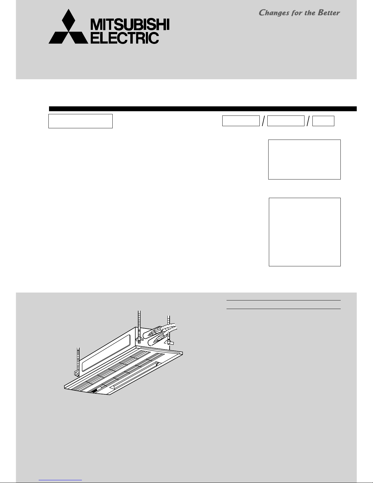
TECHNICAL & SERVICE MANUAL
SPLIT-TYPE, HEAT PUMP AIR CONDITIONERS
Indoor unit
[Model names] [Service Ref.]
No. OC307
REVISED EDITION-D
INDOOR UNIT
CONTENTS
1. TECHNICAL CHANGES
.....................
2
2. SAFETY PRECAUTION
......................
2
3. PART NAMES AND FUNCTIONS
......
6
4. SPECIFICATIONS
...............................
8
5. OUTLINES AND DIMENSIONS
........
12
6. WIRING DIAGRAM
...........................
13
7.
REFRIGERANT SYSTEM DIAGRAM
.....
16
8. TROUBLE SHOOTING
.....................
17
9. DISASSEMBLY PROCEDURE
.........
26
10. PARTS LIST
......................................
30
11. RoHS PARTS LIST
...........................
33
Ceiling Cassettes
Series PMFY
R407C
R22
R410A
October 2009
Note:
• This manual describes only
service data of the indoor
units.
• RoHS compliant products
have <G> mark on the spec
name plate.
• For servicing RoHS compliant products, refer to the
RoHS Parts List.
Revision:
•
PMFY-P20/25/32/40VBM-ER3
are added in REVISED
EDITION-D.
• Some descriptions have
been modified.
• Please void OC307
REVISED EDITION-C.
PMFY-P20VBM-E
PMFY-P25VBM-E
PMFY-P32VBM-E
PMFY-P40VBM-E
PMFY-P20VBM-E
PMFY-P20VBM-E
1
PMFY-P20VBM-E#2
PMFY-P20VBM-ER3
PMFY-P25VBM-E
PMFY-P25VBM-E
1
PMFY-P25VBM-E#2
PMFY-P25VBM-ER3
PMFY-P32VBM-E
PMFY-P32VBM-E
1
PMFY-P32VBM-E#2
PMFY-P32VBM-ER3
PMFY-P40VBM-E
PMFY-P40VBM-E
1
PMFY-P40VBM-E#2
PMFY-P40VBM-ER3
2
2
SAFETY PRECAUTION
Cautions for units utilizing refrigerant R407C
CAUTIONS RELATED TO NEW REFRIGERANT
Use ESTR , ETHER or HAB as the lubricant to
coat flares and flange connection parts.
If large amount of mineral oil enters, that can cause
deterioration of refrigerant oil etc.
Use liquid refrigerant to seal the system.
If gas refrigerant is used to seal the system, the composition
of the refrigerant in the cylinder will change and performance
may drop.
Do not use a refrigerant other than R407C.
If another refrigerant (R22, etc.) is used, the chlorine in the
refrigerant may cause the lubricant deterioration.
Use a vacuum pump with a reverse flow check valve.
The vacuum pump oil may flow back into the refrigerant
cycle and cause the lubricant deterioration.
Store the piping to be used indoors during
installation, and both ends sealed until just
before brazing.
(Store elbows and other joints in a plastic bag.)
If dust, dirt, or water enters the refrigerant cycle,
deterioration of the oil and compressor trouble may result.
Ventilate the room if refrigerant leaks during
operation. If refrigerant comes into contact with
a flame, poisonous gases will be released.
Use new refrigerant pipes.
Make sure that the inside and outside of refrigerant piping is clean and it has no contamination
such as sulfur hazardous for use, oxides, dirt,
shaving particles, etc.
In addition, use pipes with specified thickness.
In case of using the existing pipes for R22, be careful with
the followings.
· Change flare nut to the one provided with this product.
Use a newly flared pipe.
· Avoid using thin pipes.
Contamination inside refrigerant piping can cause deterioration of refrigerant oil etc.
1
TECHNICAL CHANGES
PMFY-P20VBM-E PMFY-P20VBM-E1
PMFY-P25VBM-E PMFY-P25VBM-E1
PMFY-P32VBM-E PMFY-P32VBM-E1
PMFY-P40VBM-E PMFY-P40VBM-E1
1. FAN MOTOR (MF) has been changed.
2. CONTROLLER BOARD (I.B) has been changed.
PMFY-P20VBM-E1 PMFY-P20VBM-E#2
PMFY-P25VBM-E1 PMFY-P25VBM-E#2
PMFY-P32VBM-E1 PMFY-P32VBM-E#2
PMFY-P40VBM-E1 PMFY-P40VBM-E#2
1. CONTROLLER BOARD (I.B) has been changed.
2. PANEL has been changed.
PMP-40BM → PMP-40BMW
(White : 0.98Y 8.99/0.63) (Pure white : 6.4Y 8.9/0.4)
3. FAN MOTOR (MF) has been changed.
4. THERMISTOR (TH22, TH23) have been changed.
PMFY-P20VBM-E#2 PMFY-P20VBM-ER3
PMFY-P25VBM-E#2 PMFY-P25VBM-ER3
PMFY-P32VBM-E#2
PMFY-P32VBM-ER3
PMFY-P40VBM-E#2 PMFY-P40VBM-ER3
1. DRAIN PIPE has been changed.
2. JOINT SOCKET (FOR DRAIN PIPE) has been added.
33
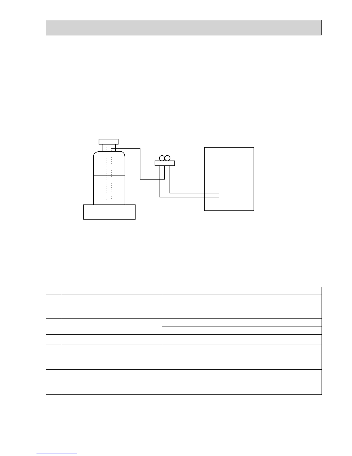
[2] Refrigerant recharging
(1) Refrigerant recharging process
1Direct charging from the cylinder
· R407C cylinder are available on the market has a syphon pipe.
· Leave the syphon pipe cylinder standing and recharge it.
(By liquid refrigerant)
(2) Recharge in refrigerant leakage case
· After recovering the all refrigerant in the unit, proceed to working.
· Do not release the refrigerant in the air.
· After completing the repair service, recharge the cycle with the specified amount of liquid refrigerant.
[3] Service tools
Use the below service tools as exclusive tools for R407C refrigerant.
[1] Cautions for service
· After recovering all the refrigerant in the unit, proceed to working.
· Do not release refrigerant in the air.
· After completing the repair service, recharge the cycle with the specified amount of liquid refrigerant.
Gravimeter
Unit
No. Tool name Specifications
1
Gauge manifold · Only for R407C
· Use the existing fitting SPECIFICATIONS. (UNF7/16)
· Use high-tension side pressure of 3.43MPa·G or over.
2
Charge hose · Use the existing fitting SPECIFICATIONS. (UNF7/16)
· Use pressure performance of 5.10MPa·G or over.
3
Electronic scale
—
4
Gas leak detector · Use the detector for R134a or R407C.
5
Adapter for reverse flow check · Attach on vacuum pump.
6
Refrigerant charge base
—
7
Refrigerant cylinder · For R407C · Top of cylinder (Brown)
· Cylinder with syphon
8
Refrigerant recovery equipment
—
4
Cautions for units utilizing refrigerant R410A
Store the piping to be used indoors during
installation, and both ends of the piping sealed
until just before brazing. (Leave elbow joints, etc.
in their packaging.)
Use ester oil, ether oil or alkylbenzene oil (small
amount) as the refrigerant oil applied to flares
and flange connections.
Charge refrigerant from liquid phase of gas
cylinder.
If the refrigerant is charged from gas phase, composition
change may occur in refrigerant and the efficiency will be
lowered.
Do not use refrigerant other than R410A.
If other refrigerant (R22 etc.) is used, chlorine in refrigerant can cause deterioration of refrigerant oil etc.
Use a vacuum pump with a reverse flow check
valve.
Vacuum pump oil may flow back into refrigerant cycle and
that can cause deterioration of refrigerant oil etc.
Use the following tools specifically designed for
use with R410A refrigerant.
The following tools are necessary to use R410A refrigerant.
Handle tools with care.
If dirt, dust or moisture enters into refrigerant cycle, that can
cause deterioration of refrigerant oil or malfunction of compressor.
Do not use a charging cylinder.
If a charging cylinder is used, the composition of refrigerant will change and the efficiency will be lowered.
Flare tool
Electronic refrigerant
charging scale
Vacuum pump adaptor
Size adjustment gauge
Gauge manifold
Torque wrench
Gas leak detector
Charge hose
Tools for R410A
If dirt, dust or moisture enters into refrigerant cycle, that can
cause deterioration of refrigerant oil or malfunction of compressor.
If large amount of mineral oil enters, that can cause deterioration of refrigerant oil etc.
Ventilate the room if refrigerant leaks during
operation. If refrigerant comes into contact with
a flame, poisonous gases will be released.
Use new refrigerant pipes.
Make sure that the inside and outside of refrigerant piping is clean and it has no contamination
such as sulfur hazardous for use, oxides, dirt,
shaving particles, etc.
In addition, use pipes with specified thickness.
In case of using the existing pipes for R22, be careful with
the followings.
· Change flare nut to the one provided with this product.
Use a newly flared pipe.
· Avoid using thin pipes.
Contamination inside refrigerant piping can cause deterioration of refrigerant oil etc.

5
[1] Cautions for service
(1) Perform service after recovering the refrigerant left in unit completely.
(2) Do not release refrigerant in the air.
(3) After completing service, charge the cycle with specified amount of refrigerant.
(4) When performing service, install a filter drier simultaneously.
Be sure to use a filter drier for new refrigerant.
[2] Additional refrigerant charge
When charging directly from cylinder
· Check that cylinder for R410A on the market is syphon type.
· Charging should be performed with the cylinder of syphon stood vertically. (Refrigerant is charged from liquid phase.)
Gravimeter
Unit
[3] Service tools
Use the below service tools as exclusive tools for R410A refrigerant.
No. Tool name Specifications
1
Gauge manifold · Only for R410A
· Use the existing fitting
specifications
. (UNF1/2)
· Use high-tension side pressure of 5.3MPa·G or over.
2
Charge hose · Only for R410A
· Use pressure performance of 5.09MPa·G or over.
3
Electronic scale
—
4
Gas leak detector · Use the detector for R134a, R407C or R410A.
5
Adapter for reverse flow check · Attach on vacuum pump.
6
Refrigerant charge base
—
7
Refrigerant cylinder · Only for R410A · Top of cylinder (Pink)
· Cylinder with syphon
8
Refrigerant recovery equipment
—
6
3
PART NAMES AND FUNCTIONS
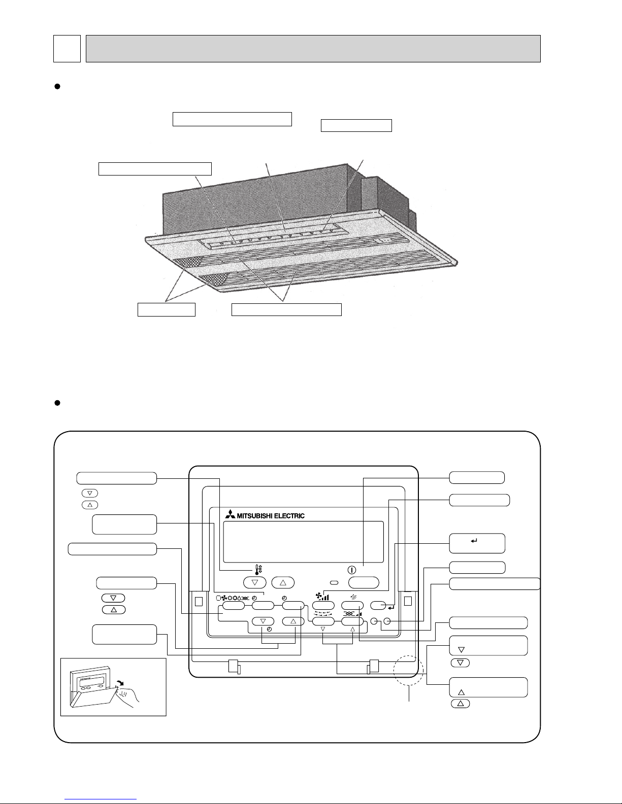
Indoor Unit
Guide vane
Air flow can be changed to horizontal
by moving the Guide vane to the left or right.
Air intake
Returns air from room.
Filters
Remove dust and pollutants
from return air.
Auto Air Swing Vane
Disperses airflow up and
down and adjusts the angle
of airflow direction.
Horizontal Air Outlet
PAR-21MAA
ON/OFF
FILTER
CHECK
OPERATION
CLEAR
TEST
TEMP.
MENU
BACK DAY
MONITOR/SET
CLOCK
ON/OFF
Temperature setting buttons
Down
Up
Timer Menu button
(Monitor/Set button)
Mode button (Return button)
Set Time buttons
Back
Ahead
Timer On/Off button
(Set Day button)
Opening the
lid
ON/OFF button
Fan Speed button
Filter button
(<Enter> button)
Test Run button
Check button (Clear button)
Airflow Up/Down button
Louver button
( Operation button)
To return operation
number
Ventilation button
( Operation button)
To go to next operation
number
Built-in temperature sensor
Wired remote controller
Once the controllers are set, the same operation mode can be repeated by simply pressing the ON/OFF button.
77
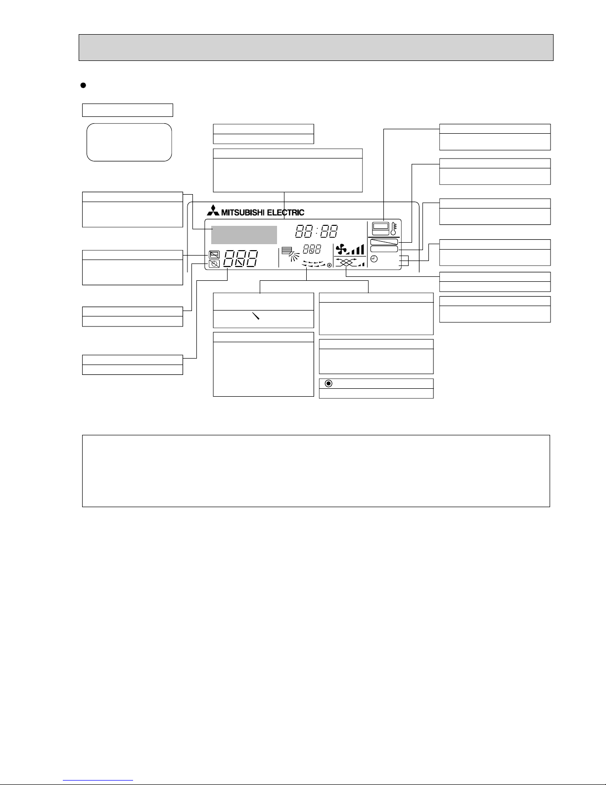
Wired remote controller
●
●
°F°C
°F°C
ERROR CODE
AFTER
TIMER
TIME SUN MON TUE WED THU FRI SAT
ON
OFF
Hr
AFTER
FILTER
FUNCTION
ONLY1Hr.
WEEKLY
SIMPLE
AUTO OFF
Note:
“PLEASE WAIT” message
This message is displayed for approximately 3 minutes when power is supplied to the indoor unit or when the unit is recovering from a power failure.
“NOT AVAILABLE” message
This message is displayed if an invalid button is pressed (to operate a function that the indoor unit does not have).
If a single remote controller is used to operate multiple indoor units simultaneously that are different types, this message will not be displayed as
far as any of the indoor units is equipped with the function.
Display Section
For purposes of this explanation,
all parts of the display are shown
as lit. During actual operation, only
the relevant items will be lit.
Identifies the current operation
Shows the operating mode, etc.
*Multilanguage display is available.
“Centrally Controlled” indicator
Indicates that operation from the
remote controller has been prohibited by a master controller.
“Timer is Off” indicator
Indicates that the timer is off.
Temperature Setting
Shows the target temperature.
Day-of-Week
Shows the current day of the week.
Time/Timer Display
Shows the current time, unless the simple or Auto Off
timer is set.
If the simple or Auto Off timer is set, the time to be
switched off is shown.
“Sensor” indication
Displayed when the remote controller
sensor is used.
“Locked” indicator
Indicates that remote controller buttons have been locked.
“Clean The Filter” indicator
To be displayed on when it is time to
clean the filter.
Timer indicators
The indicator comes on if the corresponding timer is set.
Up/Down Air Direction indicator
The indicator shows the direction
of the outcoming airflow.
“One Hour Only” indicator
Room Temperature display
Shows the room temperature. The room
temperature display range is 8-39.
The display blinks if the temperature
is less than
8 or 39
or more.
Louver display
Indicates the action of the swing louver.
Does not appear if the louver is not
running.
(Power On indicator)
Indicates that the power is on.
Fan Speed indicator
Shows the selected fan speed.
Ventilation indicator
Appears when the unit is running in
Ventilation mode.
Displayed if the airflow is set to
low or downward during COOL
or DRY mode. (Operation varies
according to model.)
The indicator goes off in one hour,
when the airflow direction also
changes.
8
4
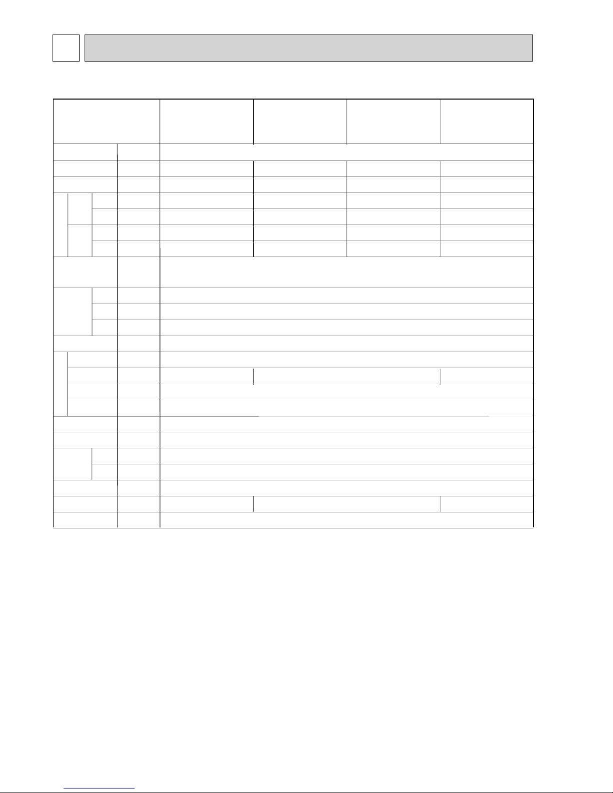
SPECIFICATIONS
4-1. SPECIFICATION
Note 1. Rating conditions (JIS B 8615-1)
Cooling: Indoor: D.B. 27°C W.B. 19°C
outdoor: D.B. 35°C
Heating: Indoor: D.B. 20°C
outdoor: D.B. 7°C W.B. 6°C
Note 2. The number indicated in < > is for the grille.
W 3. Air flow and the noise level are indicated as High – Medium1 – Medium2 – Low.
Item
V
·Hz
kW
kW
kW
kW
A
A
—
mm
mm
mm
—
—
G/min
Pa
kW
—
—
:mm(in.)
:mm(in.)
:mm
dB
kg
Cooling capacity
Power
Heat exchanger
Insulator
Air filter
Fan × No
Air flow 3
Pipe
dimensions
Field drain pipe size
Noise level 3
Product weight
Exterior
(munsell symbol)
Fan motor
output
External
static pressure
Liquid
side
Gas
side
Heating capacity
Dimensions
Height
Width
Depth
Electric characteristic
Input
Cooling
Heating
Cooling
Heating
Current
PMFY-P20VBM-E
PMFY-P20VBM-E
1
PMFY-P20VBM-E#2
PMFY-P20VBM-ER3
PMFY-P25VBM-E
PMFY-P25VBM-E
1
PMFY-P25VBM-E#2
PMFY-P25VBM-ER3
PMFY-P32VBM-E
PMFY-P32VBM-E
1
PMFY-P32VBM-E#2
PMFY-P32VBM-ER3
PMFY-P40VBM-E
PMFY-P40VBM-E
1
PMFY-P40VBM-E#2
PMFY-P40VBM-ER3
Single phase 220V-230V-240V 50Hz / 220V 60Hz
2.2
2.5
0.042
0.042
0.20
0.20
2.8
3.2
0.044
0.044
0.21
0.21
3.6
4.0
0.044
0.044
0.21
0.21
4.5
5.0
0.054
0.054
0.26
0.26
9.3-8.6-8.0-7.3
37-36-34-32
8.7-8.0-7.2-6.5
35-33-30-27
10.7-9.7-8.7-7.7
39-37-35-33
Unit : Galvanized sheets · Standard grilles : ABS resin acrylic coating
Munsell <0.98Y 8.99/0.63> (PMFY-P·VBM-E
(1)) / <6.4Y 8.9/0.4> (PMFY-P·VBM-E#2/ER3)
230<30>
812<1,000>
395<470>
Cross fin
Line flow fan × 1
0
0.028
Polyethylene sheet
PP honey comb fabric
12.7(1/2")
6.35(1/4")
O.D.26 (PVC pipe VP-20 connectable)
14<3.0>
F a n
99
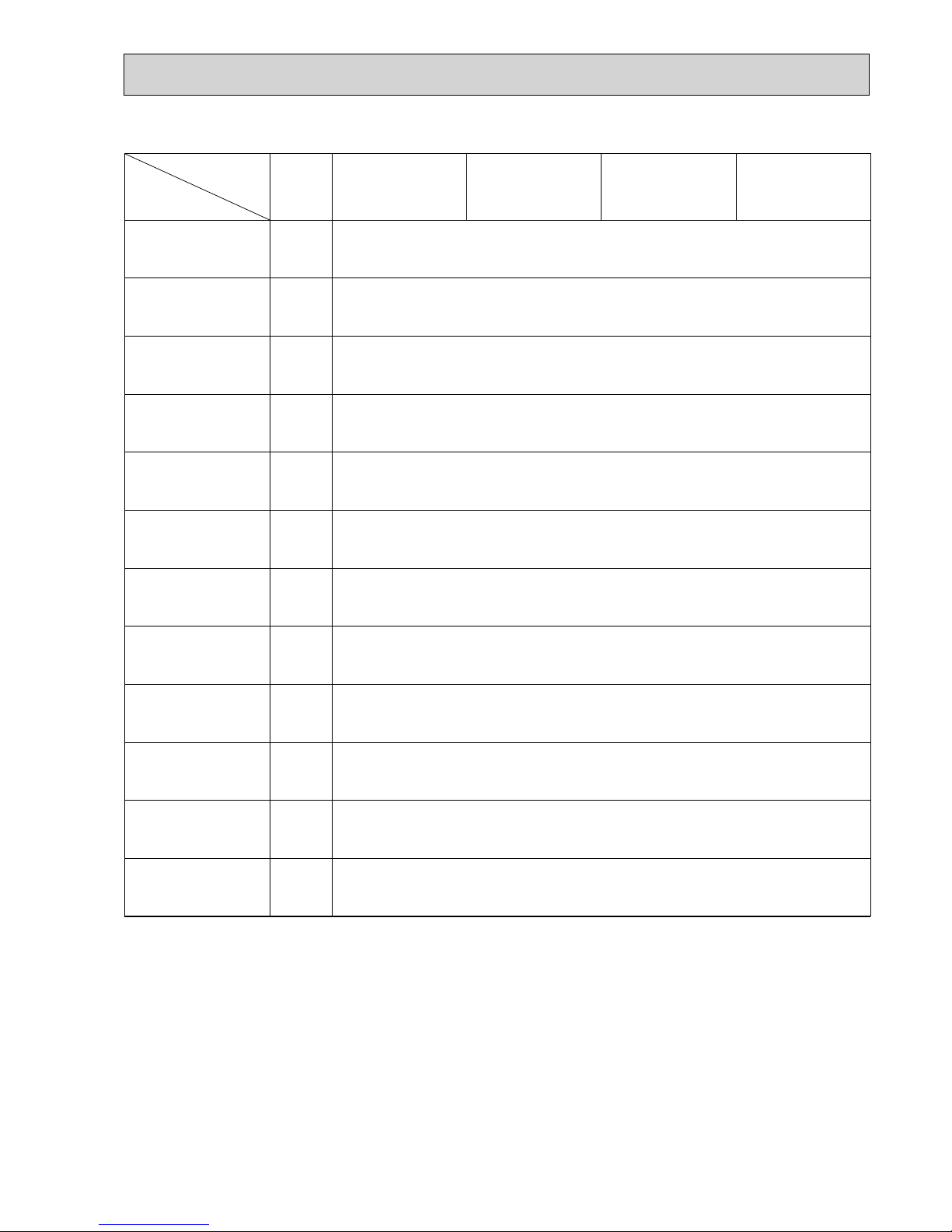
4-2. ELECTRIC PARTS SPECIFICATIONS
Parts name
Service ref.
Symbol
TH21
TH22
TH23
FUSE
MF
MV
DP
DS
LEV
TB2
TB5
TB15
Resistance 0/15k, 10/9.6k, 20/6.3k, 25/5.4k, 30/4.3k, 40/3.0k
Resistance 0/15k, 10/9.6k, 20/6.3k, 25/5.4k, 30/4.3k, 40/3.0k
Resistance 0/15k, 10/9.6k, 20/6.3k, 25/5.4k, 30/4.3k, 40/3.0k
250V 6.3A
Thermistor resistance 0/6k, 10/3.9k, 20/2.6k, 25/2.2k, 30/1.8k, 40/1.3k
(L, N, ) 330V 30A
(M1, M2, S) 250V 20A
(1,2) 250V 10A
Liquid pipe thermistor
Gas pipe thermistor
Drain pump
Drain sensor
Linear expansion valve
PMFY-P20VBM-E
PMFY-P20VBM-E
1
PMFY-P20VBM-E#2
PMFY-P20VBM-ER3
PMFY-P25VBM-E
PMFY-P25VBM-E1
PMFY-P25VBM-E#2
PMFY-P25VBM-ER3
PMFY-P32VBM-E
PMFY-P32VBM-E1
PMFY-P32VBM-E#2
PMFY-P32VBM-ER3
PMFY-P40VBM-E
PMFY-P40VBM-E1
PMFY-P40VBM-E#2
PMFY-P40VBM-ER3
Room temperature
thermistor
Fuse
(Indoor controller board)
Fan motor
Vane motor
Power supply
terminal block
Transmission
terminal block
DC Brushless Motor
8-pole OUTPUT 28W
PN0H28-MB
MSFJC 20M23
12V/380
PJV-1046
220-240V 50/60Hz
DC12V Stepping motor drive, Port dimension :3.2
(0~2000pulse)
MA-remote controller
terminal block
10
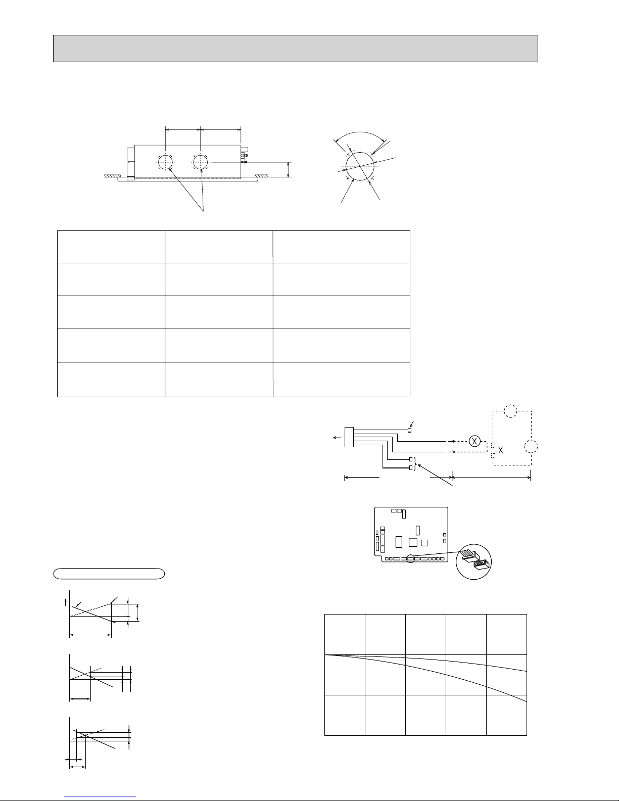
4-3. AIR CAPACITY TAKEN FROM OUTSIDE
PMFY-P·VBM-E series enables to take fresh air from outside. When taking fresh air, the duct fan is used.
The air capacity should be 20% or less of the air flow SPEC(Hi).
50.0
-50.0
-100.0
0.0 0.5 1.0
Air flow (m
3
/min)
2 intakes
1 intake
Characteristic diagram of fresh air taken capacity
Static pressure (Pa)
1.5 2.0 2.5
0.0
PMFY-P20VBM-E
PMFY-P20VBM-E
1
PMFY-P20VBM-E#2
PMFY-P20VBM-ER3
PMFY-P25VBM-E
PMFY-P25VBM-E
1
PMFY-P25VBM-E#2
PMFY-P25VBM-ER3
PMFY-P32VBM-E
PMFY-P32VBM-E
1
PMFY-P32VBM-E#2
PMFY-P32VBM-ER3
PMFY-P40VBM-E
PMFY-P40VBM-E
1
PMFY-P40VBM-E#2
PMFY-P40VBM-ER3
8.7m³/min
9.3m³/min
9.3m³/min
10.7m³/min
Max 1.74m³/min
Max 1.86m³/min
Max 1.86m³/min
Max 2.14m³/min
Air flow
(Hi)
Air capacity from outside
Service Ref.
(Knockout)
4-W2.8
Fresh air intake hole
(Knockout)
Fresh air intake hole
90
W
122
W
100
108
250 288.5
Unit : mm
Installation at site
1
~
CN51
Multiple remote
controller adapter
PAC-SA88HA-E
Indoor controller board
Distance between indoor
controller board and relay
must be within 10m.
Be sure to secure insulation
material by tape, etc.
5
Green
Yellow
Orange
Connector (5P)
Indoor unit side
Multiple remote
controller adapter
PAC-SA88HA-E
Be sure to secure insulatio
n
material by tape, etc.
CN51
on
indoor unit
board
Red
Brown
MB
Q
0
B
A
C
Curve in the
right graphs
Duct characteristics
at site
Q
A
EC
Q
Qa
AD
Operation in conjunction with duct fan (Booster fan)
● Whenever the indoor unit is operating, the duct fun
operates.
(1) Connect the optional multiple remote controller
adapter(PAC-SA88HA-E) to the connector CN51
on the indoor controller board.
(2) Drive the relay after connecting the 12V DC relay
between the Yellow and Orange connector lines.
(w) Use a relay of 1W or smaller.
MB: Electromagnetic switch power relay for duct fan.
X: Auxiliary relay (12V DC LY-1F)
How to read curves
Q…Designed amount of fresh air intake
<m
3
/min>
A…Static pressure loss of fresh air
intake duct system with air flow
amount Q <Pa>
B…Forced static pressure at air condi-
tioner inlet with air flow amount Q
<Pa>
C…Static pressure of booster fan with
air flow amount Q <Pa>
D…Static pressure loss increase amount
of fresh air intake duct system for air
flow amount Q <Pa>
E…Static pressure of indoor unit with air
flow amount Q <Pa>
Qa…Estimated amount of fresh air
intake without D <m3/min>
11
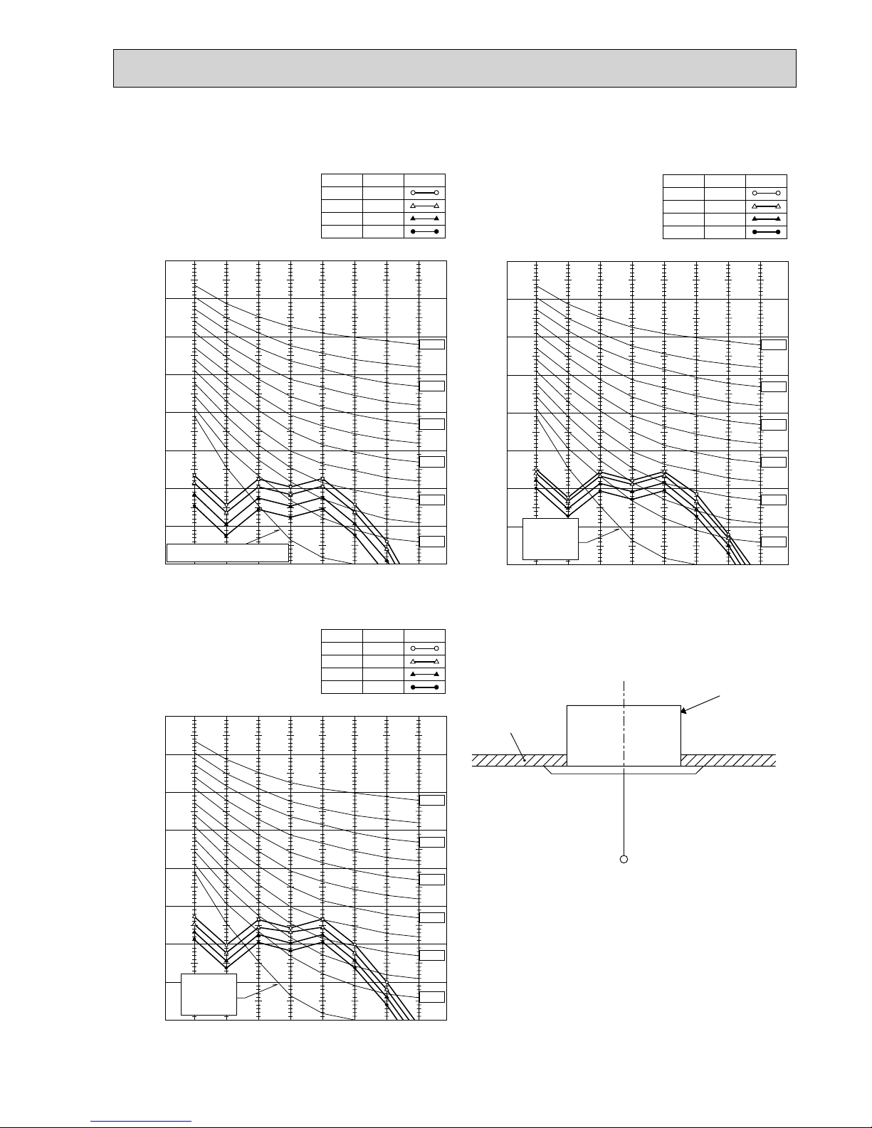
4-4. NOISE CRITERION CURVES
90
80
70
60
50
40
30
20
10
63 125 250 500 1000 2000 4000 8000
APPROXIMATE THRESHOLD OF HEARING
FOR CONTINUOUS NOISE
NC-60
NC-50
NC-40
NC-30
NC-20
NC-70
BAND CENTER FREQUENCIES, Hz
PMFY-P20VBM-E
PMFY-P20VBM-E1
PMFY-P20VBM-E#2
PMFY-P20VBM-ER3
High
NOTCH
Medium1
Medium2
Low
35
SPL(dB)
33
30
27
LINE
OCTAVE BAND SOUND PRESSURE LEVEL, dB (0 dB = 0.0002 μbar)
90
80
70
60
50
40
30
20
10
63 125 250 500 1000 2000 4000 8000
APPROXIMATE
THRESHOLD OF
HEARING FOR
CONTINUOUS
NOISE
NC-60
NC-50
NC-40
NC-30
NC-20
NC-70
BAND CENTER FREQUENCIES, Hz
PMFY-P25VBM-E
PMFY-P32VBM-E
PMFY-P25VBM-E
1
PMFY-P32VBM-E1
PMFY-P25VBM-E#2
PMFY-P32VBM-E#2
PMFY-P25VBM-ER3
PMFY-P32VBM-ER3
High
NOTCH
Medium1
Medium2
Low
37
SPL(dB)
36
34
32
LINE
OCTAVE BAND SOUND PRESSURE LEVEL, dB (0 dB = 0.0002 μbar)
90
80
70
60
50
40
30
20
10
63 125 250 500 1000 2000 4000 8000
APPROXIMATE
THRESHOLD OF
HEARING FOR
CONTINUOUS
NOISE
NC-60
NC-50
NC-40
NC-30
NC-20
NC-70
BAND CENTER FREQUENCIES, Hz
PMFY-P40VBM-E
PMFY-P40VBM-E1
PMFY-P40VBM-E#2
PMFY-P40VBM-ER3
High
NOTCH
Medium1
Medium2
Low
39
SPL(dB)
37
35
33
LINE
OCTAVE BAND SOUND PRESSURE LEVEL, dB (0 dB = 0.0002 μbar)
UNIT
1.5m
MICROPHONE
CEILING
 Loading...