

Mitsubishi PM75RVA060 Datasheet
MITSUBISHI INTELLIGENT POWER MODULES
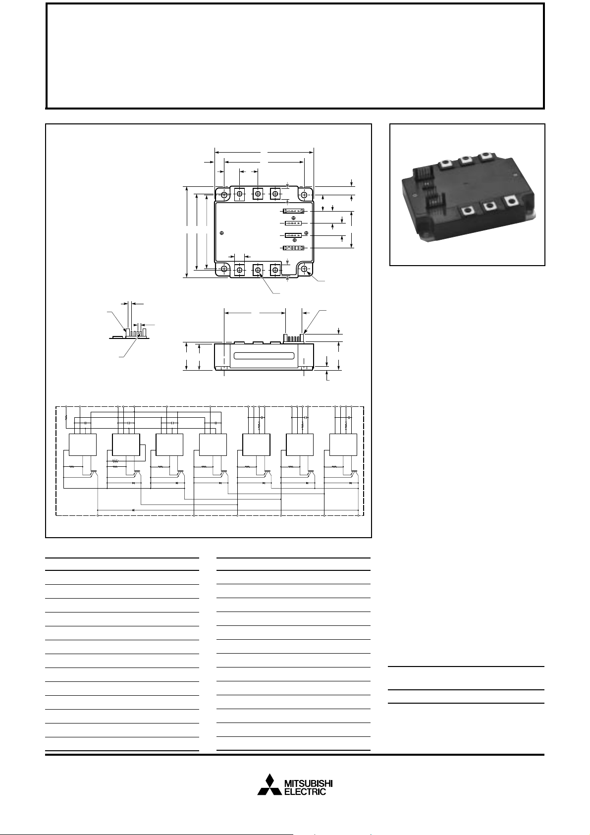
PM75RVA060
FLAT-BASE TYPE
INSULATED PACKAGE
TERMINAL CODE
1. W
FO
2. V
WPC
3. W
P
4. V
WP1
5. V
FO
6. V
VPC
7. V
P
8. V
VP1
9. U
FO
10. V
UPC
CCφ
(4 PLACES)
BB SQ PIN - TYP.
(19 PLACES)
F
Br
O
Rf
O
GND
F
O
CC
V
IN
OUT
GND
Si
Rf
O
= 1.5k OHM
11. U
P
12. V
UP1
13. Br
14. F
O
15. VNC
16. VN1
17. UN
18. VN
19. WN
B K E
AA - TYP.
Z - TYP.
C
DETAIL A
VNC
VN1
WN
GND
F
O
V
CC
IN
TEMP
OUT
GND
Si
TH
GND
GND
VN
F
O
V
CC
IN
OUT
Si
A
DP
J
N
TYP.
NPB
M
1234
P
R
U
L - TYP.
UVW
XW
5678
9101112
1314 1516
17 1819
M
S NUTS (6 TYP.)
V
U
T (4 TYP.)
SEE
DETAIL A
H
Description:
Mitsubishi Intelligent Power Modules are isolated base modules designed for power switching applications operating at frequencies to
20kHz. Built-in control circuits pro-
Y
G
vide optimum gate drive and protection for the IGBT and free-wheel
F
V
V
W
WPC
UN
W
FO
P
V
WP1
V
VPC
V
FO
P
V
V
VP1
V
U
UPC
UP1
U
FO
P
diode power devices.
Features:
u Complete Output Power
GND
GND
F
IN
Si
GND
O
V
CC
OUT
GND
F
IN
Si
GND
O
V
CC
OUT
GND
F
IN
Si
GND
O
V
CC
OUT
GND
F
O
V
CC
IN
OUT
Si
Circuit
u Gate Drive Circuit
u Protection Logic
– Short Circuit
– Over Temperature
– Under Voltage
BNWVUP
Outline Drawing and Circuit Diagram
Dimensions Inches Millimeters
A 4.33 110.0
B 3.50 89.0
C 0.87 +0.04/-0.02 22.0 +1.0/-0.5
D 3.74±0.010 95.0±0.25
E 2.91±0.010 74.0±0.25
F 0.16 4.0
G 0.87 22.0
H 0.42 10.6
J 0.79 20.0
K 2.99±0.02 76.0±0.5
L 0.39 10.0
M 0.49 12.5
N 0.67 17.0
Dimensions Inches Millimeters
P 0.30 7.5
R 0.65 16.5
S M5 Metric M5
T 0.22 Dia. Dia. 5.5
U 0.56±0.010 14.1±0.25
V 1.72±0.012 43.57±0.3
W 0.57±0.012 14.6±0.3
X 2.90 73.7
Y 0.78 19.7
Z 0.10±0.010 2.54±0.25
AA 1.37±0.010 3.49±0.25
BB 0.02 SQ 0.64 SQ
CC
0.12 +0.04/-0.02 3.0 +1.0/-0.5
Applications:
u Inverters
u UPS
u Motion/Servo Control
u Power Supplies
Ordering Information:
Example: Select the complete
part number from the table below
-i.e. PM75RVA060 is a 600V,
75 Ampere Intelligent Power Module.
Type Current Rating V
Amperes Volts (x 10)
PM 75 60
CES
Sep.1998

MITSUBISHI INTELLIGENT POWER MODULES
PM75RVA060
FLAT-BASE TYPE
INSULATED PACKAGE
Absolute Maximum Ratings, Tj = 25°C unless otherwise specified
Ratings Symbol PM75RVA060 Units
Power Device Junction Temperature T
Storage Temperature T
Case Operating Temperature T
j
stg
C
Mounting Torque, M5 Mounting Screws — 2.5~3.5 N · m
Mounting Torque, M5 Main Terminal Screws — 2.5~3.5 N · m
Module Weight (Typical) — 560 Grams
Supply Voltage (Applied between P - N, Surge Value) V
Supply Voltage Protected by SC (VD = 13.5 ~16.5V, Inverter Part, Tj = 125°C Start) V
Isolation Voltage (Main Terminal to Baseplate, AC 1 min.) V
CC(surge)
CC(prot.)
iso
Control Sector
Supply Voltage (Applied between V
UP1-VUPC
Input Voltage (Applied between UP-V
Fault Output Supply Voltage (Applied between FO-VNC, *FO-V
Fault Output Current (Sink Current at UFO, VFO, WFO and FO T erminal) I
UPC
, VP-V
, V
VP1-VVPC
VPC
, WP-V
, V
WP1-VWPC
, UN · VN · WN · Br-VNC)V
WPC
*PC
, VN1-VNC)V
D
CIN
)VFO20 V olts
FO
-20 to 150 °C
-40 to 125 °C
-20 to 100 °C
500 Volts
400 Volts
2500 Vrms
20 V olts
20 V olts
20 mA
IGBT Inverter Sector
Collector-Emitter Voltage (VD = 15V, V
Collector Current, (TC = 25°C) I
Peak Collector Current, (TC = 25°C) I
Collector Dissipation (TC = 25°C) P
= 15V) V
CIN
Brake Sector
Collector-Emitter Voltage (VD = 15V, V
Collector Current, (TC = 25°C) I
Peak Collector Current, (TC = 25°C) I
Collector Dissipation (TC = 25°C) P
FWDi Forward Current (TC = 25°C) I
FWDi Rated DC Reverse Voltage (TC = 25°C) V
= 15V) V
CIN
CES
C
CP
C
CES
C
CP
C
F
R(DC)
600 Volts
75 Amperes
150 Amperes
284 Watts
600 Volts
30 Amperes
60 Amperes
178 Watts
30 Amperes
600 Volts
Sep.1998

MITSUBISHI INTELLIGENT POWER MODULES
PM75RVA060
FLAT-BASE TYPE
INSULATED PACKAGE
Electrical and Mechanical Characteristics, Tj = 25°C unless otherwise specified
Characteristics Symbol Test Conditions Min. Typ. Max. Units
Control Sector
Over Current Trip Level Brake Part OC -20°C ≤ Tj ≤ 125°C, VD = 15V 39 — — Amperes
Short Circuit Trip Level Inverter Part SC -20°C ≤ Tj ≤ 125°C, VD = 15V 115 — — Amperes
Short Circuit Trip Level Brake Part — 94 — Amperes
Short Circuit Current Shut-off Time t
Over Temperature Protection OT Trip Level 100 110 120 °C
(VD = 15V, Lower Arm) OT
Supply Circuit Under Voltage Protection UV Trip Level 11.5 12.0 12.5 Volts
(-20°C ≤ Tj ≤ 125°C) UV
Circuit Current I
Input ON Threshold Voltage V
Input OFF Threshold Voltage V
Fault Output Current I
Minimum Fault Output Pulse Width t
*Fault output is given only when the internal SC, OT, and UV protections circuits of either an upper-arm or a lower-arm device operate to protect it.
off(SC)
D
th(on)
th(off)
FO(H)
I
FO(L)
FO
r
r
VD = 15V, V
V
= 15V, V
D
Applied between UP-V
WP-V
VD = 15V — 10 — µs
Reset Level 85 95 105 °C
Reset Level — 12.5 — Volts
= 15V, VN1-V
CIN
= 15V, V
CIN
UPC
, UN · VN · WN · Br-V
WPC
VD = 15V, VFO = 15V* — — 0.01 mA
VD = 15V, VFO = 15V* — 10 15 mA
VD = 15V* 1.0 1.8 — ms
NC
XP1-VXPC
, VP-V
VPC
NC
—4460mA
—1318mA
, 1.2 1.5 1.8 Volts
1.7 2.0 2.3 Volts
Sep.1998
 Loading...