

Page 1

GROUP 00
GENERAL
CONTENTS
GENERAL . . . . . . . . . . . . . . . . . . . . . . . . . . . . . . . . . . . . . . . . . . 00
GENERAL <ELECTRICAL> . . . . . . . . . . . . . . . . . . . . . . . . . . . . 00E
00-1
Page 2

NOTES
Page 3

GROUP 00
GENERAL
CONTENTS
00-1
VEHICLE IDENTIFICATION . . . . . . . 00-2
MODELS. . . . . . . . . . . . . . . . . . . . . . . . . . . 00-2
VEHICLE IDENTIFICATION NUMBER
(CHASSIS NUMBER) . . . . . . . . . . . . . . . . . 00-3
GENERAL DATA AND
SPECIFICATIONS . . . . . . . . . . . . . . . 00-4
PRECAUTIONS BEFORE
SERVICE. . . . . . . . . . . . . . . . . . . . . . . 00-8
CODING LIST . . . . . . . . . . . . . . . . . . . . . . . 00-8
Page 4
00-2
GENERAL
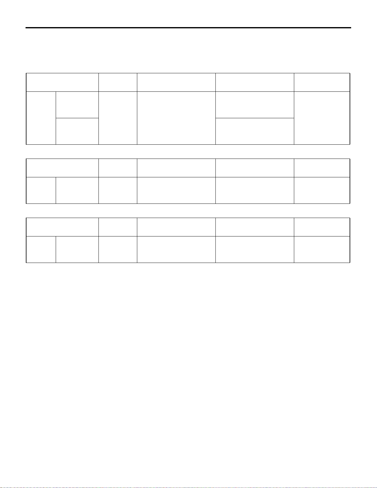
VEHICLE IDENTIFICATION
VEHICLE IDENTIFICATION
MODELS
<2000>
Model code Seating
capacity
GF2W XTSHLAZ 5-persons 4B11 (1,998 mL) DOHC
XTSHZLAZ W1CJC (Electronic
<2400>
Model code Seating
capacity
GF3W XTHHZLAZ 5-persons 4B12 (2,360 mL) DOHC
<3000>
Model code Seating
capacity
GF4W XLHYZLAZ 5-persons 6B31 (2,998 mL)
Engine model Transm ission model Fuel supply
MIVEC petrol engine
Engine model Transm ission model Fuel supply
MIVEC petrol engine
Engine model Transm ission model Fuel supply
SOHC MIVEC petrol
engine
F1CJC (Front wheel
drive 2WD, INVECS-III
CVT with sport mode)
control 4WD, INVECS-III
CVT with sport mode)
W1CJC (Electronic
control 4WD, INVECS-III
CVT with sport mode)
W6AJA (Electronic
control 4WD, INVECS-II
6A/T with sport mode)
M1001000308668
system
MPI
system
MPI
system
MPI
Page 5
GENERAL
12345678910
ACD04356
AB
LLHYZ AZ4
ACC03409
AB
Cowl top panel
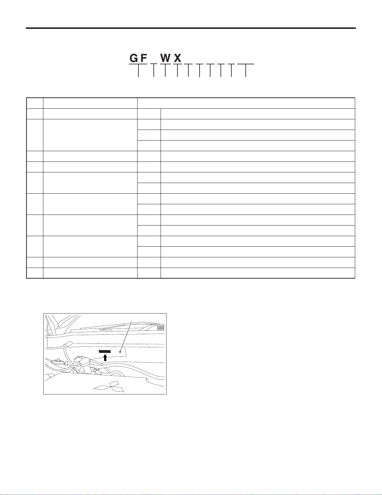
VEHICLE IDENTIFICATION
MODEL CODE
No. Item Content
1 Development GF OUTLANDER
2 Engine type 2 2.0L MPI (4B11) MIVEC
3 2.4L MPI (4B12) MIVEC
4 3.0L MPI (6B31) MIVEC
3 Vehicle type W Station wagon
4 Body style X 4-door with tailgate
5 Transmission type L 6A/T
T CVT
6 Trim level (Price class) H INTENSE <2400>, INSTYLE <3000>
S INFORM, INVITE
00-3
7 Engine specification H MIVEC (DOHC)
Y MIVEC (SOHC)
8 Special feature None 2WD
Z 4WD
9 Steering wheel location L Left-hand Drive
10 Destination AZ Vehicles for Russia
VEHICLE IDENTIFICATION NUMBER (CHASSIS NUMBER)
M1001005603960
The vehicle identification number (chassis number)
is stamped on the cowl top panel inside the engine
compartment.
Page 6

00-4
ACD04362
1234 678 95
XWMGF
LG4
AD
ACE03172
AB
1
2
345
6
7
8
9
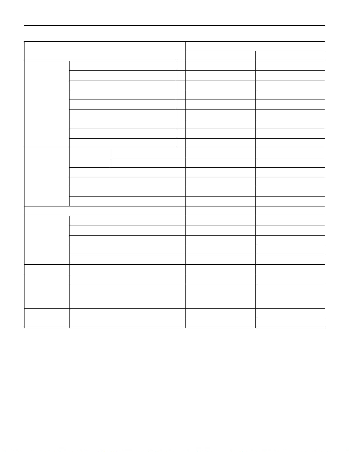
GENERAL DATA AND SPECIFICATIONS
GENERAL
CODE CHART
No. Item Content
1 World Manufacturer Identifier (WMI) Z8T PCMA-rus
2 Body type X 4-door with tailgate
3 Transmission L 6A/T
T CVT
4 Development order GF OUTLANDER
5 Engine type 2 2.0L MPI (4B11) MIVEC
3 2.4L MPI (4B12) MIVEC
4 3.0L MPI (6B31) MIVEC
6 Vehicle type W Station wagon
7 Model year G 2016 year
8 Assembly plant M Kaluga (PCMA-rus)
9 Serial number 900001 to 940000
GENERAL DATA AND SPECIFICATIONS
M1001000909083
Page 7
GENERAL
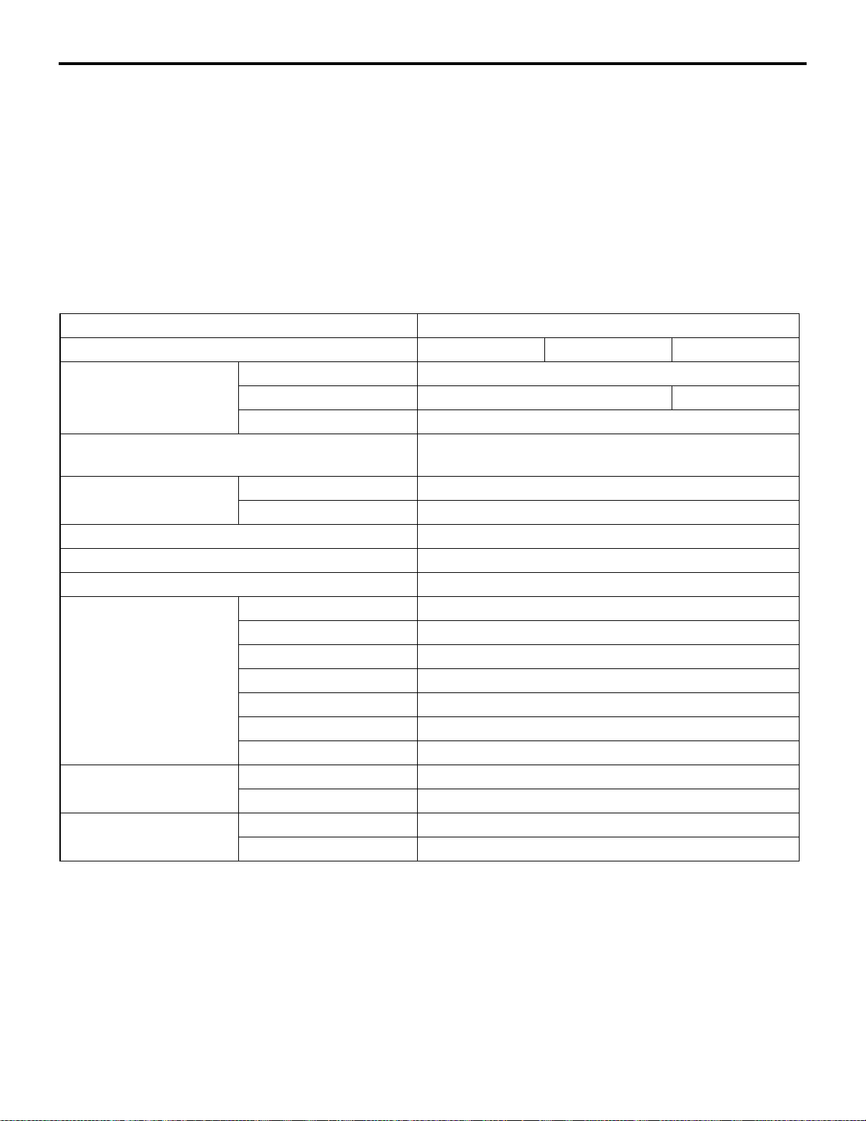
GENERAL DATA AND SPECIFICATIONS
<2000>
Item GF2W
XTSHLAZ XTSHZLAZ
Vehicle
dimension mm
Vehicle weight kgKerb weight Without full optional parts 1,425 1,490
Front track 1 1,540 1,540
Overall width 2 1,810 1,810
Front overhang 3 990 990
Wheelbase 4 2,670 2,670
Rear overhang 5 1,035 1,035
Overall length 6 4,695 4,695
Ground clearance (unladen) 7 215 215
Overall height (unladen) 8 1,680 1,680
Rear track 9 1,540 1,540
With full optional parts 1,507 1,582
Gross vehicle weight 1,985 1,985
Gross axle weight rating-front 1,150 1,150
00-5
Gross axle weight rating-rear 1,250 1,250
Gross combination weight 3,665 3,665
Seating capacity 5 5
Engine Model No. 4B11 4B11
Type DOHC MIVEC DOHC MIVEC
Total displacement mL 1,998 1,998
Max. output <EEC> kW/rpm 107/6,000 107/6,000
Max. torque <EEC> N⋅m/rpm 196/4,200 196/4,200
Fuel system Fuel supply system MPI MPI
Transmission Model code F1CJC W1CJC
Type Front wheel drive 2WD,
INVECS-III CVT with
sport mode
Turning radius mBody 5.73 5.73
Wheel 5.3 5.3
Electronic control 4WD,
INVECS-III CVT with
sport mode
Page 8

00-6
<2400>
Item GF3W
Vehicle
dimension mm
Vehicle weight kgKerb weight Without full optional parts 1,505
Front track 1 1,540
Overall width 2 1,810
Front overhang 3 990
Wheelbase 4 2,670
Rear overhang 5 1,035
Overall length 6 4,695
Ground clearance (unladen) 7 215
Overall height (unladen) 8 1,680
Rear track 9 1,540
With full optional parts 1,592
Gross vehicle weight 2,210
Gross axle weight rating-front 1,150
GENERAL DATA AND SPECIFICATIONS
GENERAL
XTHHZLAZ
Gross axle weight rating-rear 1,250
Gross combination weight 3,890
Seating capacity 5
Engine Model No. 4B12
Type DOHC MIVEC
Total displacement mL 2,360
Max. output <EEC> kW/rpm 123/6,000
Max. torque <EEC> N⋅m/rpm 222/4,100
Fuel system Fuel supply system MPI
Transmission Model code W1CJC
Type Electronic control 4WD,
INVECS-III CVT with
sport mode
Turning radius mBody 5.73
Wheel 5.3
Page 9

GENERAL
GENERAL DATA AND SPECIFICATIONS
<3000>
Item GF4W
XLHYZLAZ
Vehicle
dimension mm
Vehicle weight kgKerb weight Without full optional parts 1,580
Front track 1 1,540
Overall width 2 1,810
Front overhang 3 990
Wheelbase 4 2,670
Rear overhang 5 1,035
Overall length 6 4,695
Ground clearance (unladen) 7 215
Overall height (unladen) 8 1,680
Rear track 9 1,540
With full optional parts 1,646
Gross vehicle weight 2,270
Gross axle weight rating-front 1,150
00-7
Gross axle weight rating-rear 1,250
Gross combination weight 3,950
Seating capacity 5
Engine Model No. 6B31
Type SOHC MIVEC
Total displacement mL 2,998
Max. output <EEC> kW/rpm 169/6,250
Max. torque <EEC> N⋅m/rpm 292/3,750
Fuel system Fuel supply system MPI
Transmission Model code W6AJA
Type Electronic control 4WD,
INVECS-II 6A/T with
sport mode
Turning radius mBody 5.73
Wheel 5.3
Page 10

00-8
GENERAL
PRECAUTIONS BEFORE SERVICE
PRECAUTIONS BEFORE SERVICE
CODING LIST
M1001015003174
The coding data of engine-ECU and ETACS-ECU
has been changed.
ENGINE ECU CODING DATA LIST
NOTE: The items to be displayed may differ depending on the version of the M.U.T.-III.
Item name Initial value
Final gear ratio 6.026 <4B1>
3.360 <6B3>
Adaptive cruise control Not present or Present
ETACS-ECU CODING DATA LIST
NOTE: The items to be displayed may differ depending on the version of the M.U.T.-III.
Item name Initial value
Corner sensor control unit Not present
FCM function Not present or Present
FCM type Undefined or Type 1
ACC type Undefined or Type 5
ACC Not present or Present
ACC function Not present or Present
DRL*1 type
DRL function
Head Lamp Leveling system type OUTLANDER LED
T/M oil cooler Present (B)
EPS type Type 4 or Type 5 or Type 11
TCL Type Not present or Type 7 or Type 11 or Type 12
ACC Type for A.S.C. Not present or Type 9
FCM Type for A.S.C. Not present or Type 2
Battery heater type Not present
NOTE: .
*1
•
: TPMS is an abbreviation of Tyre Pressure
Monitoring System, DRL of Daytime Running
Lamp.
*2
•
: The setting can be changed by the option
coding.
*2
Independent DRL
Present/Chg Ng
Page 11

GROUP 00E
GENERAL
<ELECTRICAL>
CONTENTS
00E-1
OUTLINE OF CHANGE . . . . . . . . . . . 00E-2
COMPONENT LOCATIONS. . . . . . . . . . . . 00E-2
CONFIGURATION DIAGRAMS . . . . . . . . . 00E-2
CIRCUIT DIAGRAMS . . . . . . . . . . . . . . . . . 00E-4
Page 12

00E-2
GENERAL <ELECTRICAL>
OUTLINE OF CHANGE
OUTLINE OF CHANGE
COMPONENT LOCATIONS
Location of changes Reference
page
RELAY
ECU
SENSOR
FUSIBLE LINK AND
FUSE
P.70-2
P.70-3
P.70-4
P.70-5
M1001016000543
Description of changes
• A daytime running lamp relay has been added. <6B3>
• Heated windshield relays 1 and 2 have been added.
• The EPS-ECU has been relocated as the EPS-ECU and the EPS
motor have been integrated as one unit.
• A LED headlamp control unit has been added.
• The sensors below have been added due to the introduction of
automatic anti-dazzling mirrors.
• Front lamp sensor
• Rear lamp sensor
• The sensors below have been changed or added due to the
introduction of a new CVT.
• The installation position of the primary pulley speed sensor has
been changed.
• The installation position of the secondary pulley speed sensor
has been changed.
• The installation position of the turbine speed sensor has been
added.
• Due to the introduction of a heated windshield, fusible link Nos. 6 to
12 have been added.
CONFIGURATION DIAGRAMS
Connector
symbol
A ENGINE
Name Reference
4B1
COMPARTMENT
page
P.80-2
M1001016100722
Description of change
• Due to the change in the headlamp
assembly, the number of the headlamp
assembly (LH, RH) (A-27, 37) connector
terminals has been reduced from 6 to 8.
• The number of the front wiring harness
and fog lamp wiring harness
combination connector (A-33) terminals
has been changed from 4 to 2.
• Due to the adoption of a heated
windshield, the following connectors
have been added.
• Heated windshield relay 2 (A-60X)
• Heated windshield relay 1 (A-61X)
• Heated windshield (A-147)
• The CVT control relay (A-07X) has been
discontinued.
Page 13

GENERAL <ELECTRICAL>
OUTLINE OF CHANGE
00E-3
Connector
symbol
A ENGINE
B ENGINE AND
C INSTRUMENT PANEL
Name Reference
6B3
COMPARTMENT
4B1
TRANSMISSION
page
P.80-4
P.80-6
P.80-8
Description of change
• Due to the addition of vehicles with
daytime running lamp, daytime running
lamp relay connector (A-10X) has been
added.
• Due to the change in the headlamp
assembly, the number of the headlamp
assembly (LH, RH) (A-27, 37) connector
terminals has been reduced from 6 to 8.
• The number of the front wiring harness
and fog lamp wiring harness
combination connector (A-33) terminals
has been changed from 4 to 2.
• Due to the adoption of a heated
windshield, the following connectors
have been added.
• Heated windshield relay 2 (A-60X)
• Heated windshield relay 1 (A-61X)
• Heated windshield (A-147)
• Due to the adoption of an adaptive
cruise control system (ACC) and forward
collision mitigation (FCM), the following
connectors have been added.
• J/C (CAN2) (integrated in relay box)
<Vehicles with ACC> (A-123)
• ACC/FCM -ECU (A-125)
• Due to the change of the CVT assembly,
turbine speed sensor (B-149) has been
added.
• The number of J/C (CAN3, CAN1)
(C-27, 29) connector terminals and the
connector colour have been changed
from "22-GR" to "18".
• Due to the introduction of forward
collision mitigation (FCM), FCM ON/OFF
switch (C-132) has been added.
• Due to the introduction of heated
windshield, heated windshield switch
(C-152) has been added.
• Due to the adoption of the EPS-ECU
integrated with the motor, the following
connectors have been changed or
added.
• The terminal numbers of EPS-ECU
(C-218) connector has been changed
from 4 to 8.
• Front wiring harness and EPS sub
wiring harness combination (C-246,
247) has been added.
Page 14

00E-4
GENERAL <ELECTRICAL>
OUTLINE OF CHANGE
Connector
symbol
D FLOOR
E ROOF
G TAILGATE
Name Reference
page
P.80-13
P.80-15
P.80-16
Description of change
• The terminal number and colour of floor
wiring harness and tailgate wiring
harness (LH) combination connector
<Vehicles with electric tailgate> (D-112)
have been changed from "15-L" to "14".
• No connection (D-138, 139) has been
added.
• Inside rear view mirror assembly
connector (E-19) has been added due to
the introduction of automatic
anti-dazzling mirrors.
• The colour of back-up lamp (RH)
connector (G-25) has been changed
from "B" to "GR."
• Tail lamps (RH and LH) (G-26 and 28)
have been added.
• The pin number and colour of the rear
end wiring harness-to-rear bumper
wiring harness combination connector
has been changed from "13-GR" to "6."
Due to this, this connector identification
has been changed from "G-18" to
"G-27."
CIRCUIT DIAGRAMS
Main title Sub title Reference
page
J/C
CENTRALIZED
JUNCTION
POWER
DISTRIBUTION
SYSTEM
− P.90-4
− P.90-7
− P.90-16
M1001008400944
Description of changes
• The J/C has been changed as the following
equipment and model have been added.
• A new CVT
• Tail lamps mounted on the tailgate
• Heated windshield
• Due to the introduction of a heated windshield,
fusible link Nos. 6 to 12 (in engine
compartment) and heated windshield relays 1
and 2 have been added.
• Due to the introduction of a heated windshield,
the circuit has been changed.
Page 15

GENERAL <ELECTRICAL>
OUTLINE OF CHANGE
00E-5
Main title Sub title Reference
page
IGNITION
SYSTEM
CHARGING
SYSTEM
ENGINE
CONTROL
SYSTEM
COOLING
SYSTEM
4B1
6B3
− P.90-24
4B1
6B3
4B1
6B3
P.90-20
P.90-22
P.90-26
P.90-29
P.90-33
P.90-35
Description of changes
• Due to the following change, the circuit
diagrams have been changed.
• The heated windshield has been introduced.
• The number of the J/C (CAN1, CAN3)
connector terminals has been changed.
• Due to the following change, the circuit
diagrams have been changed.
• The heated windshield has been introduced.
• The adaptive cruise control system (ACC)
has been added.
• The number of the J/C (CAN1, CAN3)
connector terminals has been changed.
• Due to the following change, the circuit
diagrams have been changed.
• The heated windshield has been introduced.
• The CVT-ECU has been changed due to the
introduction of a new CVT.
• The number of the J/C (CAN1, CAN3)
connector terminals has been changed.
• Due to the following change, the circuit
diagrams have been changed.
• A circuit between engine-ECU (B-07)
terminal No. 82 and J/C (6) (C-28) terminal
No. 7 has been added.
• The heated windshield has been introduced.
• The adaptive cruise control system (ACC)
has been added.
• The number of the J/C (CAN1, CAN3)
connector terminals has been changed.
• Due to the following change, the circuit
diagrams have been changed.
• The heated windshield has been introduced.
• The number of the J/C (CAN1, CAN3)
connector terminals has been changed.
• Due to the following change, the circuit
diagrams have been changed.
• The heated windshield has been introduced.
• The adaptive cruise control system (ACC)
has been added.
• The number of the J/C (CAN1, CAN3)
connector terminals has been changed.
Page 16

00E-6
GENERAL <ELECTRICAL>
OUTLINE OF CHANGE
Main title Sub title Reference
page
SHIFT LOCK
MECHANISM
CVT
A/T
HEADLAMP
TAIL LAMP,
POSITION LAMP,
LICENCE PLATE
LAMP AND
LAMP
REMINDER
BUZZER
− P.90-37
− P.90-38
− P.90-41
− P.90-44
− P.90-47
Description of changes
• Due to the introduction of a heated windshield,
the circuit diagram has been changed.
• Due to the following change, the circuit
diagrams have been changed.
• A new CVT adopted
• The heated windshield has been introduced.
• The number of the J/C (CAN1, CAN3)
connector terminals has been changed.
• Due to the following change, the circuit
diagrams have been changed.
• The heated windshield has been introduced.
• The adaptive cruise control system (ACC)
has been added.
• The number of the J/C (CAN1, CAN3)
connector terminals has been changed.
• Due to the following change, the circuit
diagrams have been changed.
• A LED headlamp has been introduced.
• A halogen headlamp assembly has been
changed.
• The heated windshield has been introduced.
• The number of the J/C (CAN3) connector
terminals has been changed.
• Due to the following change, the circuit
diagrams have been changed.
• The headlamp assembly has been changed
in conjunction with the introduction of a LED
position lamp.
• Tail lamps have been added on the tailgate.
• The heated windshield has been introduced.
• The number of the J/C (CAN3) connector
terminals has been changed.
HEADLAMP
MANUAL
LEVELLING
SYSTEM
HEADLAMP
AUTOMATIC
LEVELLING
SYSTEM
− P.90-50
− P.90-51
• Due to the following change, the circuit
diagrams have been changed.
• The heated windshield has been introduced.
• Headlamp assembly has been changed.
• Due to the following change, the circuit
diagrams have been changed.
• Headlamp assembly has been changed.
• The heated windshield has been introduced.
• The number of the J/C (CAN1, CAN3)
connector terminals has been changed.
Page 17

GENERAL <ELECTRICAL>
OUTLINE OF CHANGE
00E-7
Main title Sub title Reference
page
DAYTIME
RUNNING LAMP
(DRL)
FRONT FOG
LAMP
REAR FOG
LAMP
ROOM LAMP,
LUGGAGE
COMPARTMENT
LAMP AND
IGNITION KEY
CYLINDER
ILLUMINATION
LAMP
V ANITY MIRROR
LAMP
GLOVE BOX
LAMP
TURN-SIGNAL
LAMP AND
HAZARD
WARNING LAMP
STOP LAMP
− P.90-53
− P.90-55
− P.90-57
− P.90-59
− P.90-62
− P.90-63
− P.90-64
− P.90-66
Description of changes
• Due to the following change, the circuit
diagrams have been changed.
• Integrated in the headlamp assembly.
• The heated windshield has been introduced.
• The adaptive cruise control system (ACC)
has been added.
• The number of the J/C (CAN1, CAN3)
connector terminals has been changed.
• Due to the following change, the circuit
diagrams have been changed.
• The heated windshield has been introduced.
• The number of the front wiring harness and
fog lamp wiring harness combination (A-33)
connector terminals has been changed.
• The number of the J/C (CAN3) connector
terminals has been changed.
• Due to the following change, the circuit
diagrams have been changed.
• The heated windshield has been introduced.
• The rear end wiring harness and rear bumper
wiring harness combination connector has
been reassigned from "G-18" to "G-27" .
• The number of the J/C (CAN3) connector
terminals has been changed.
• Due to the following change, the circuit
diagrams have been changed.
• The heated windshield has been introduced.
• The number of the J/C (CAN3) connector
terminals has been changed.
• Due to the adoption of a heated windshield, the
circuit diagram has been changed.
• Due to the following change, the circuit
diagrams have been changed.
• The heated windshield has been introduced.
• Headlamp assembly has been changed.
• The number of the J/C (CAN3) connector
terminals has been changed.
• Due to the introduction of a heated windshield,
the circuit diagram has been changed.
Page 18

00E-8
GENERAL <ELECTRICAL>
OUTLINE OF CHANGE
Main title Sub title Reference
page
BACK-UP LAMP
HORN
METER AND
GAUGE
FUEL WARNING
LAMP, OIL
PRESSURE
WARNING LAMP
AND BRAKE
WARNING LAMP
POWER
WINDOWS
− P.90-67
− P.90-68
− P.90-69
− P.90-71
− P.90-73
Description of changes
• Due to the following change, the circuit
diagrams have been changed.
• The heated windshield has been introduced.
• The rear end wiring harness and rear bumper
wiring harness combination connector has
been reassigned from "G-18" to "G-27" .
• The back-up lamp (LH, RH) connectors
(G-09, 25) have been reshaped.
• Due to the introduction of a heated windshield,
the circuit diagram has been changed.
• Due to the following change, the circuit
diagrams have been changed.
• The heated windshield has been introduced.
• The number of the J/C (CAN1, CAN3)
connector terminals has been changed.
• Due to the following change, the circuit
diagrams have been changed.
• The heated windshield has been introduced.
• The number of the J/C (CAN3) connector
terminals has been changed.
CENTRAL DOOR
LOCKING
SYSTEM
ELECTRIC
TAILGATE
AIR
CONDITIONER
WINDSHIELD
WIPER AND
WASHER
VEHICLES WITHOUT
KOS
VEHICLES WITH KOS
− P.90-82
− P.90-85
− P.90-88
P.90-75
P.90-78
• Due to the following change, the circuit
diagrams have been changed.
• The heated windshield has been introduced.
• The CVT-ECU has been changed due to the
introduction of a new CVT.
• The number of the J/C (CAN1, CAN3)
connector terminals has been changed.
• Due to the following change, the circuit
diagrams have been changed.
• The heated windshield has been introduced.
• The CVT-ECU has been changed due to the
introduction of a new CVT.
• The number of the J/C (CAN1, CAN3)
connector terminals has been changed.
• The number of the floor wiring harness and
tailgate wiring harness (LH) combination
(D-112) connector has been changed.
• Due to the following change, the circuit
diagrams have been changed.
• The heated windshield has been introduced.
• The number of the J/C (CAN1, CAN3)
connector terminals has been changed.
Page 19

GENERAL <ELECTRICAL>
OUTLINE OF CHANGE
00E-9
Main title Sub title Reference
page
REAR WIPER
AND WASHER
HEADLAMP
WASHER
REAR WINDOW
DEFOGGER
WIPER DEICER
HEATED
WINDSHIELD
HEATED DOOR
MIRROR
REMOTE
CONTROLLED
MIRROR
− P.90-90
− P.90-92
− P.90-93
− P.90-94
− P.90-96
− P.90-98
− P.90-100
Description of changes
• Due to the following change, the circuit
diagrams have been changed.
• The heated windshield has been introduced.
• The number of the J/C (CAN3) connector
terminals has been changed.
• Due to the change in the J/C (CAN3) connector,
the circuit has been changed.
• Due to the introduction of a heated windshield,
a new circuit diagram has been established.
• Due to the following change, the circuit
diagrams have been changed.
• The heated windshield has been introduced.
• The number of the J/C (CAN3) connector
terminals has been changed.
• Due to the introduction of a heated windshield,
the circuit diagram has been changed.
ELECTRIC
RETRACTABLE
REMOTE
CONTROLLED
MIRROR
AUTOMATIC
ANTI-DAZZLING
MIRROR
AUDIO SYSTEM
MMCS
− P.90-102
− P.90-105
− P.90-106
− P.90-109
• Due to the following change, the circuit
diagrams have been changed.
• The heated windshield has been introduced.
• The number of the J/C (CAN1, CAN3)
connector terminals has been changed.
• This circuit diagram has been added due to the
introduction of automatic anti-dazzling mirrors.
• Due to the following change, the circuit
diagrams have been changed.
• The heated windshield has been introduced.
• The power supply circuit to the radio and CD
player has been changed.
• The number of the J/C (CAN1, CAN3)
connector terminals has been changed.
• Due to the following change, the circuit
diagrams have been changed.
• The heated windshield has been introduced.
• The power supply circuits to the multivision
display and the CAN box unit have been
changed.
• The number of the J/C (CAN1, CAN3)
connector terminals has been changed.
Page 20

00E-10
GENERAL <ELECTRICAL>
OUTLINE OF CHANGE
Main title Sub title Reference
page
HANDS-FREE
INTERFACE
SYSTEM
SPARE
CONNECTOR
(FOR AUDIO)
ACCESSORY
SOCKET AND
CIGARETTE
LIGHTER
IMMOBILIZER
SYSTEM
KEY INTERLOCK VEHICLES WITHOUT
ONE-TOUCH
START SYSTEM
(OSS)
CRUISE
CONTROL
SYSTEM
VEHICLES WITHOUT
MMCS
VEHICLES WITH
MMCS
− P.90-116
− P.90-118
VEHICLES WITHOUT
KOS
KOS
− P.90-121
− P.90-124
P.90-112
P.90-114
P.90-119
P.90-120
Description of changes
• Due to the following change, the circuit
diagrams have been changed.
• The heated windshield has been introduced.
• The power supply circuit to the
handsfree-ECU has been changed.
• The number of the J/C (CAN1, CAN3)
connector terminals has been changed.
• Due to the following change, the circuit
diagrams have been changed.
• The heated windshield has been introduced.
• The power supply circuit to the spare
connector (for audio) has been changed.
• The number of the J/C (CAN1, CAN3)
connector terminals has been changed.
• Due to the introduction of a heated windshield,
the circuit diagram has been changed.
• Due to the following change, the circuit
diagrams have been changed.
• The heated windshield has been introduced.
• The number of the J/C (CAN1, CAN3)
connector terminals has been changed.
• Due to the introduction of a heated windshield,
the circuit diagram has been changed.
• Due to the following change, the circuit
diagrams have been changed.
• The heated windshield has been introduced.
• The number of the J/C (CAN1, CAN3)
connector terminals has been changed.
• Due to the following change, the circuit
diagrams have been changed.
• The heated windshield has been introduced.
• A circuit between engine-ECU (B-07)
terminal No. 82 and J/C (6) (C-28) terminal
No. 7 has been added <6B3>.
• The number of the J/C (CAN1, CAN3)
connector terminals has been changed.
• The CVT-ECU has been changed due to the
introduction of a new CVT.
Page 21

GENERAL <ELECTRICAL>
OUTLINE OF CHANGE
00E-11
Main title Sub title Reference
page
ADAPTIVE
CRUISE
CONTROL
SYSTEM (ACC)
AND FORWARD
COLLISION
MITIGATION
(FCM)
ANTI-SKID
BRAKING
SYSTEM (ABS)
ACTIVE
STABILITY
CONTROL (ASC)
AND HILL ST ART
ASSIST (HSA)
− P.90-126
− P.90-131
− P.90-133
Description of changes
• New circuits have been added as an adaptive
cruise control system (ACC) and forward
collision mitigation (FCM) have been introduced
on vehicles with 6B3 engine.
• Due to the following change, the circuit
diagrams have been changed.
• The heated windshield has been introduced.
• The number of the J/C (CAN1, CAN3)
connector terminals has been changed.
• Due to the following change, the circuit
diagrams have been changed.
• The heated windshield has been introduced.
• The CVT-ECU has been changed due to the
introduction of a new CVT.
• The adaptive cruise control system (ACC)
has been added.
• The number of the J/C (CAN1, CAN3)
connector terminals has been changed.
ELECTRONICAL
LY
CONTROLLED
4WD
SUPER ALL
WHEEL
CONTROL
(S-AWC)
SUNROOF
SUPPLEMENTAL
RESTRAINT
SYSTEM (SRS)
− P.90-136
− P.90-138
− P.90-140
− P.90-142
• Due to the following change, the circuit
diagrams have been changed.
• The heated windshield has been introduced.
• The number of the J/C (CAN1, CAN3)
connector terminals has been changed.
• Due to the following change, the circuit
diagrams have been changed.
• The heated windshield has been introduced.
• The EPS-ECU has been changed.
• The adaptive cruise control system (ACC)
has been added.
• The number of the J/C (CAN1, CAN3)
connector terminals has been changed.
• Due to the following change, the circuit
diagrams have been changed.
• The heated windshield has been introduced.
• The number of the J/C (CAN3) connector
terminals has been changed.
Page 22

00E-12
GENERAL <ELECTRICAL>
OUTLINE OF CHANGE
Main title Sub title Reference
page
ELECTRIC
POWER
STEERING
SYSTEM
HEATED SEAT
POWER SEAT
REAR VIEW
CAMERA
DOOR AJAR
WARNING
BUZZER
SEAT BELT
WARNING
PARKING
BRAKE
REMINDER
BUZZER
− P.90-145
− P.90-147
− P.90-149
VEHICLES WITH
DISPLAY AUDIO
− P.90-151
− P.90-153
− P.90-155
P.90-150
Description of changes
• Due to the following change, the circuit
diagrams have been changed.
• The heated windshield has been introduced.
• The EPS-ECU and the EPS motor have been
integrated as one unit.
• The number of the J/C (CAN1, CAN3)
connector terminals has been changed.
• Due to the introduction of a heated windshield,
the circuit diagram has been changed.
• Due to the following change, the circuit
diagrams have been changed.
• The heated windshield has been introduced.
• The number of the J/C (CAN3) connector
terminals has been changed.
• Due to the following change, the circuit
diagrams have been changed.
• The heated windshield has been introduced.
• The number of the J/C (CAN1, CAN3)
connector terminals has been changed.
CAN
SPARE
CONNECTOR
(FOR TRAILER
LAMPS)
− P.90-157
− P.90-159
• Due to the following change, the circuit
diagrams have been changed.
• The number of the J/C (CAN1, CAN3)
connector terminals has been changed.
• The heated windshield has been introduced.
• The CVT-ECU has been changed due to the
introduction of a new CVT.
• The EPS-ECU has been changed.
• The adaptive cruise control system (ACC)
has been added.
• Due to the introduction of a heated windshield,
the circuit diagram has been changed.
Page 23

GROUP 13
FUEL
CONTENTS
MULTIPOINT FUEL INJECTION (MPI) <4B1> . . . . . . . . . . . . . 13A
MULTIPOINT FUEL INJECTION (MPI) <6B3> . . . . . . . . . . . . . 13F
13-1
Page 24

NOTES
Page 25

GROUP 13A
MULTIPOINT FUEL
INJECTION (MPI)
<4B1>
CONTENTS
13A-1
GENERAL INFORMATION . . . . . . . . 13A-2
Page 26

13A-2
MULTIPOINT FUEL INJECTION (MPI) <4B1>
GENERAL INFORMATION
GENERAL INFORMATION
OUTLINE OF CHANGES
• The engine-ECU has been changed.
• Due to the change of the engine-ECU, diagnosis
code No. P0125 has been discontinued.
GENERAL SPECIFICATIONS
Items Specifications
Engine-ECU Identification
No.
Vehicles without heated windshield E6T79775 <4B11 - Euro4>
Vehicles with heated windshield E6T79777 <4B11 - Euro4>
The other service procedures are the same as the
conventional ones.
E6T79874 <4B12 - Euro4>
E6T79876 <4B12 - Euro4>
M1131000107638
Page 27

GROUP 13F
MULTIPOINT FUEL
INJECTION (MPI)
<6B3>
CONTENTS
13F-1
GENERAL INFORMATION . . . . . . . . 13F-2
Page 28

13F-2
MULTIPOINT FUEL INJECTION (MPI) <6B3>
GENERAL INFORMATION
GENERAL INFORMATION
OUTLINE OF CHANGES
The engine-ECU has been changed. The other service procedures are the same as the conventional
ones.
GENERAL SPECIFICATIONS
Items Specifications
Engine-ECU Identification
No.
Vehicles without heated windshield E6T80379 <Euro4>
Vehicles with heated windshield E6T80384 <Euro4>
M1130500100059
Page 29

GROUP 14
ENGINE COOLING
CONTENTS
GENERAL INFORMATION . . . . . . . . 14-2
14-1
Page 30

14-2
ENGINE COOLING
GENERAL INFORMATION
GENERAL INFORMATION
OUTLINE OF CHANGE
The following components have been changed or
discontinued <4B1>.
The other service procedures are the same as
before.
M1141000102827
• Radiator lower hose reshaped.
• Radiator hose support discontinued.
Page 31

GROUP 15
INTAKE AND
EXHAUST
CONTENTS
GENERAL INFORMATION . . . . . . . . 15-2 EXHAUST PIPE AND MAIN
MUFFLER . . . . . . . . . . . . . . . . . . . . . . 15-2
REMOVAL AND INSTALLATION . . . . . . . . 15-2
15-1
Page 32

15-2
ACE03974
13 ± 2 N·m
Exhaust pipe damper
AB
GENERAL INFORMATION
OUTLINE OF CHANGE
The service procedure has been revised as an
exhaust pipe damper has been added on the
exhaust centre pipe <2WD>.
The other service procedures are the same as
before.
EXHAUST PIPE AND MAIN MUFFLER
REMOVAL AND INSTALLATION
<2WD>
INTAKE AND EXHAUST
GENERAL INFORMATION
M1151000102549
M1151008703946
Page 33

GROUP 17
ENGINE AND
EMISSION
CONTROL
CONTENTS
17-1
ADAPTIVE CRUISE CONTROL
SYSTEM (ACC) . . . . . . . . . . . . . . . . . 17-2
GENERAL INFORMATION. . . . . . . . . . . . . 17-2
CHECK CHART FOR
DIAGNOSIS CODES . . . . . . . . . . . . . . . . . 17-2
DIAGNOSIS CODE PROCEDURES. . . . . . 17-2
CHECK CHART FOR TROUBLE
SYMPTOMS . . . . . . . . . . . . . . . . . . . . . . . . 17-5
SYMPTOM PROCEDURES . . . . . . . . . . . . 17-5
Page 34

17-2
CAUTION
ENGINE AND EMISSION CONTROL
ADAPTIVE CRUISE CONTROL SYSTEM (ACC)
ADAPTIVE CRUISE CONTROL SYSTEM (ACC)
GENERAL INFORMATION
M1172000102083
OUTLINE OF CHANGE
Due to the addition of vehicles with adaptive cruise
control system (ACC), the service procedure has
been established. <6B3>
CHECK CHART FOR DIAGNOSIS CODES
Code No. Diagnosis item Reference page
C1776 Received ACC failure from engine-ECU
C1786 Received limp home from T/M-ECU
U0100 Engine CAN timeout
U0101 T/M CAN timeout
P.17-2
P.17-3
P.17-3
P.17-4
DIAGNOSIS CODE PROCEDURES
Code No. C1776: Received ACC Failure from Engine-ECU
M1172002202019
• If there is any problem in the CAN bus lines,
an incorrect diagnosis code may be set. Prior
to this diagnosis, diagnose the CAN bus
lines.
• Whenever the ECU is replaced, ensure that
the CAN bus lines are normal.
OPERATION
ACC/FCM-ECU communicates with the engine-ECU
via the CAN bus lines.
DIAGNOSIS CODE SET CONDITION
This diagnosis code is set when the abnormality
below is detected:
• A signal, which indicates a defective engine control system, is received from the engine-ECU.
PROBABLE CAUSES
• Malfunction of the CAN bus line
• Malfunction of engine-ECU
• Malfunction of ACC/FCM-ECU
DIAGNOSIS PROCEDURE
STEP 1. M.U.T.-III CAN bus diagnostics.
Use M.U.T.-III to perform the CAN bus diagnosis.
Q: Is the check result normal?
YES : Go to Step 2.
NO : Repair the CAN bus lines (Refer to GROUP
− Troubleshooting P.54C-2).
54C
STEP 2. M.U.T.-III other system diagnosis code.
Check the engine diagnosis code (Refer to GROUP
−Troubleshooting).
13F
Q: Is the diagnosis code set?
YES : Perform the relevant troubleshooting.
NO : Go to Step 3.
STEP 3. Check whether the diagnosis code is set
again.
Q: Is diagnosis code No.C1776 set?
YES : Replace the ACC/FCM-ECU.
NO : Intermittent malfunction (Refer to GROUP
− How to Cope with Intermittent
00
Malfunction).
Page 35

ENGINE AND EMISSION CONTROL
CAUTION
CAUTION
ADAPTIVE CRUISE CONTROL SYSTEM (ACC)
Code No. C1786: Received limp Home from T/M-ECU
• If there is any problem in the CAN bus lines,
an incorrect diagnosis code may be set. Prior
to this diagnosis, diagnose the CAN bus
lines.
• Whenever the ECU is replaced, ensure that
the CAN bus lines are normal.
OPERATION
ACC/FCM-ECU communicates with the A/T-ECU via
the CAN bus lines.
DIAGNOSIS CODE SET CONDITION
This diagnosis code is set when the abnormality
below is detected:
• A signal, which indicates an abnormal transmission system, is received from the A/T-ECU.
17-3
STEP 2. Use M.U.T.-III to confirm a diagnosis
code of other systems.
Check the automatic transmission (FF) diagnosis
code (Refer to GROUP 23C
Q: Is the diagnosis code set?
YES : Perform the relevant troubleshooting.
NO : Go to Step 3.
STEP 3. Check the data list.
Using M.U.T.-III, check the data list (Refer to data list
reference table).
• Item 56: transmission fail switch
Q: Is the check result normal?
YES : Go to Step 4.
NO : Go to Step 4.
−Troubleshooting).
PROBABLE CAUSES
• Malfunction of the CAN bus line
• Malfunction of A/T-ECU
• Malfunction of ACC/FCM-ECU
DIAGNOSIS PROCEDURE
STEP 1. Using M.U.T.-III, diagnose the CAN bus
line.
Use M.U.T.-III to perform the CAN bus diagnosis.
Q: Is the check result normal?
YES : Go to Step 2.
NO : Repair the CAN bus lines (Refer to GROUP
54C
− Troubleshooting P.54C-2).
Code No. U0100: Engine CAN Timeout
• If there is any problem in the CAN bus lines,
an incorrect diagnosis code may be set. Prior
to this diagnosis, diagnose the CAN bus
lines.
• Whenever the ECU is replaced, ensure that
the CAN bus lines are normal.
OPERATION
ACC/FCM-ECU communicates with the engine-ECU
via the CAN bus lines.
STEP 4. Check whether the diagnosis code is set
again.
Q: Is diagnosis code No.C1786 set?
YES : Replace the ACC/FCM-ECU.
NO : Intermittent malfunction (Refer to GROUP
− How to Cope with Intermittent
00
Malfunction).
DIAGNOSIS CODE SET CONDITION
This diagnosis code is set when the abnormality
below is detected:
• The signal sent from the engine-ECU cannot be
received for a certain period.
PROBABLE CAUSES
• Malfunction of the CAN bus line
• Malfunction of engine-ECU
• Malfunction of ACC/FCM-ECU
Page 36

17-4
CAUTION
ENGINE AND EMISSION CONTROL
ADAPTIVE CRUISE CONTROL SYSTEM (ACC)
DIAGNOSIS PROCEDURE
STEP 1. M.U.T.-III CAN bus diagnostics.
Use M.U.T.-III to perform the CAN bus diagnosis.
Q: Is the check result normal?
YES : Go to Step 2.
NO : Repair the CAN bus lines (Refer to GROUP
− Troubleshooting P.54C-2).
54C
STEP 2. M.U.T.-III other system diagnosis code.
Check the engine diagnosis code (Refer to GROUP
13F
−Troubleshooting).
Q: Is the diagnosis code set?
YES : Perform the relevant troubleshooting.
NO : Go to Step 3.
Code No. U0101: T/M CAN Timeout
• If there is any problem in the CAN bus lines,
an incorrect diagnosis code may be set. Prior
to this diagnosis, diagnose the CAN bus
lines.
• Whenever the ECU is replaced, ensure that
the CAN bus lines are normal.
STEP 3. M.U.T.-III other system diagnosis code.
Check if diagnosis code No. U0100 is set in other
ECU.
Q: Is the diagnosis code set?
YES : Replace the engine-ECU (Refer to GROUP
13F
− Engine-ECU).
NO : Go to Step 4.
STEP 4. Check whether the diagnosis code is set
again.
Q: Is diagnosis code No.U0100 set?
YES : Replace the ACC/FCM-ECU.
NO : Intermittent malfunction (Refer to GROUP
− How to Cope with Intermittent
00
Malfunction).
STEP 2. M.U.T.-III other system diagnosis code.
Check the automatic transmission (FF) diagnosis
code (Refer to GROUP 23C
Q: Is the diagnosis code set?
YES : Perform the relevant troubleshooting.
NO : Go to Step 3.
−Troubleshooting).
OPERATION
ACC/FCM-ECU communicates with the A/T-ECU via
the CAN bus lines.
DIAGNOSIS CODE SET CONDITION
This diagnosis code is set when the abnormality
below is detected:
• The signal sent from the A/T-ECU cannot be
received for a certain period.
PROBABLE CAUSES
• Malfunction of the CAN bus line
• Malfunction of A/T-ECU
• Malfunction of ACC/FCM-ECU
DIAGNOSIS PROCEDURE
STEP 1. M.U.T.-III CAN bus diagnostics.
Use M.U.T.-III to perform the CAN bus diagnosis.
Q: Is the check result normal?
YES : Go to Step 2.
NO : Repair the CAN bus lines (Refer to GROUP
− Troubleshooting P.54C-2).
54C
STEP 3. M.U.T.-III other system diagnosis code.
Check if diagnosis code No. U0101 is set in other
ECU.
Q: Is the diagnosis code set?
YES : Replace the A/T-ECU (Refer to GROUP
− A/T-ECU).
23C
NO : Go to Step 4.
STEP 4. Check whether the diagnosis code is set
again.
Q: Is diagnosis code No.U0101 set?
YES : Replace the ACC/FCM-ECU.
NO : Intermittent malfunction (Refer to GROUP
00
− How to Cope with Intermittent
Malfunction).
Page 37

ENGINE AND EMISSION CONTROL
CAUTION
ADAPTIVE CRUISE CONTROL SYSTEM (ACC)
CHECK CHART FOR TROUBLE SYMPTOMS
Trouble symptom Inspection
procedure No.
17-5
M1172002302469
Reference page
Cruise control cannot be set (No response SET − switch is
2
P.17-5
pressed).
The cruise control is cancelled although the switch is not
3
P.17-6
operated during the ACC operation.
SYMPTOM PROCEDURES
Inspection Procedure 2: Cruise Control cannot be Set (No Response SET − Switch is Pressed).
COMMENTS ON TROUBLE SYMPTOM
The conditions for initiating the adaptive cruise control system (ACC) may not be satisfied.
PROBABLE CAUSES
• Malfunction of CAN bus system.
• Damaged harness or connector.
• Malfunction of the clock spring.
• Malfunction of the cruise control switch.
• Malfunction of the stop lamp switch.
• Malfunction of the inhibitor switch <A/T>.
• Malfunction of the parking brake switch.
• Malfunction of the engine system.
• Malfunction of the ASC system.
• Malfunction of the A/T system.
• Malfunction of the ACC/FCM−ECU.
DIAGNOSIS PROCEDURE
STEP 2. Check whether the diagnosis code is set
again.
Q: Is diagnosis code set?
YES : Repair the adaptive cruise control system
(ACC) (Refer to
NO : Go to Step 3.
P.17-2).
STEP 3. Check the other system diagnosis code.
Using M.U.T.-III, perform MPI system diagnosis code
(Refer to GROUP 13F
− Troubleshooting, Diagnosis
Function).
Q: Is any diagnosis code set?
YES : Repair the MPI system (Refer to GROUP
− Troubleshooting, Inspection Chart for
13F
Diagnosis Code).
NO : Go to Step 4.
• If there is any problem in the CAN bus lines,
an incorrect diagnosis code may be set. Prior
to this diagnosis, diagnose the CAN bus
lines.
• Before replacing the ECU, ensure that the
CAN bus lines is normal.
STEP 1. Check the CAN bus system diagnosis.
Using M.U.T.-III, perform CAN bus diagnosis (Refer
to GROUP 54C
− Explanation About The M.U.T.-III
Can Bus Diagnostics).
Q: Is the check result satisfactory?
YES : Go to Step 2.
NO : Repair the CAN bus lines (Refer to GROUP
54C
− Troubleshooting, Can Bu s Diagnostic
P.54C-2). Then go to Step 2.
Table
STEP 4. Check the other system diagnosis code.
Using M.U.T.-III, perform ASC system diagnosis
code (Refer to GROUP 35C
− Troubleshooting,
Diagnosis Function).
Q: Is the diagnosis code set?
YES : Repair the ASC system (Refer to GROUP
35C
− Troubleshooting, Inspection Chart for
Diagnosis Code
NO : Go to Step 5.
P.35C-2).
STEP 5. Check the other system diagnosis code.
Using M.U.T.-III, perform A/T system diagnosis code
(Refer to GROUP 23C
− Troubleshooting, Diag nosis
Function).
Q: Is any diagnosis code set?
YES : Repair the A/T system (Refer to GROUP
23C
−Troubleshooting, Inspection Chart for
Diagnosis Code).
NO : Go to Step 6.
Page 38

17-6
CAUTION
ENGINE AND EMISSION CONTROL
ADAPTIVE CRUISE CONTROL SYSTEM (ACC)
STEP 6. Check the other symptom.
The system should be turned on when the cruise
control switch is operated.
Q: Is the system turned on by operating the cruise
control switch?
YES : Go to Step 7.
NO : Refer to "When the cruise control switch is
operated, the system is not turned on."
STEP 8. Check the cruise control switch.
Check the cruise control switch.
Q: Is the check result normal?
YES : Replace the engine-ECU (Refer to GROUP
− Engine-ECU).
13F
NO : Replace the cruise control switch.
STEP 9. Check the symptom.
(1) Drive the vehicle for approx. three minutes.
STEP 7. Check the data list.
Using M.U.T.-III, check the data list of MPI system
(Refer to data list reference table).
• Item 75: CANCEL switch
• Item 92: SET − switch
Q: Is the check result normal?
YES : Go to Step 9.
NO : Go to Step 8.
Q: Can cruise control be set?
YES : It can be assumed that this malfunction is
intermittent (Refer to GROUP 00
− How to
Use Troubleshooting/Inspection Service
Points, How to Cope with Intermittent
Malfunction).
NO : Replace the ACC/FCM-ECU.
Inspection Procedure 3: The Cruise Control is Cancelled Although The Switch is not Operated During
The ACC Operation.
COMMENTS ON TROUBLE SYMPTOM
A malfunction is detected while the adaptive cruise
control system (ACC) is activated.
PROBABLE CAUSES
• Malfunction of CAN bus system.
• Damaged harness or connector.
• Malfunction of the engine system.
• Malfunction of the ASC system.
• Malfunction of the ACC/FCM−ECU.
DIAGNOSIS PROCEDURE
• If there is any problem in the CAN bus lines,
an incorrect diagnosis code may be set. Prior
to this diagnosis, diagnose the CAN bus
lines.
• Before replacing the ECU, ensure that the
CAN bus lines is normal.
STEP 1. Check the CAN bus system diagnosis.
Using M.U.T.-III, perform CAN bus diagnosis (Refer
to GROUP 54C
Can Bus Diagnostics).
− Explanation About The M.U.T.-III
STEP 2. Check whether the diagnosis code is set
again.
Q: Is diagnosis code set?
YES : Repair the adaptive cruise control system
(ACC) (Refer to
NO : Go to Step 3.
P.17-2).
STEP 3. Check the other system diagnosis code.
• Using M.U.T.-III, perform MPI system diagnosis
code (Refer to GROUP 13F
− Troubleshooting,
Diagnosis Function).
• Using M.U.T.-III, perform cruise control system
diagnosis code (Refer to
Q: Is any diagnosis code set?
YES <MPI system> : Repair the MPI system (Refer
to GROUP 13F
P.17-2>.
− Troubleshooting,
Inspection Chart for Diagnosis Code).
YES <Cruise control system> : Repair the cruise
control system (Refer to
NO : Go to Step 4.
P.17-2).
Q: Is the check result satisfactory?
YES : Go to Step 2.
NO : Repair the CAN bus lines (Refer to GROUP
54C
− Troubleshooting, Can Bu s Diagnostic
P.54C-2). Then go to Step 2.
Table
Page 39

ENGINE AND EMISSION CONTROL
ADAPTIVE CRUISE CONTROL SYSTEM (ACC)
17-7
STEP 4. Check the other system diagnosis code.
Using M.U.T.-III, perform ASC system diagnosis
code (Refer to GROUP 35C
− Troubleshooting,
Diagnosis Function).
Q: Is the diagnosis code set?
YES : Repair the ASC system (Refer to GROUP
− Troubleshooting, Inspection Chart for
35C
Diagnosis Code
NO : Go to Step 5.
P.35C-2).
STEP 5. Check the other symptom.
The system should be turned on when the cruise
control switch is operated.
Q: Is the system turned on by operating the cruise
control switch?
YES : Go to Step 6.
NO : Refer to "When the cruise control switch is
operated, the system is not turned on."
STEP 6. Check the cruise control switch.
Check the cruise control switch.
Q: Is the check result normal?
YES : Go to Step 7.
NO : Replace the cruise control switch.
STEP 7. Check the symptom.
(1) Drive the vehicle for approx. three minutes.
Q: Is the cruise control cancelled?
YES : Replace the ACC/FCM-ECU.
NO : It can be assumed that this malfunction is
intermittent (Refer to GROUP 00
− How to
Use Troubleshooting/Inspection Service
Points, How to Cope with Intermittent
Malfunction).
Page 40

NOTES
Page 41

GROUP 23
AUTOMATIC
TRANSMISSION
CONTENTS
CVT . . . . . . . . . . . . . . . . . . . . . . . . . . . . . . . . . . . . . . . . . . . . . . . 23A
23-1
CONTINUOUSLY VARIABLE
TRANSMISSION OVERHAUL . . . . . . . . . . . . . . . . . . . . . . . . . . 23B
Page 42

NOTES
Page 43

GROUP 23A
CVT
CONTENTS
23A-1
GENERAL INFORMATION . . . . . . . . 23A-2
SERVICE SPECIFICATIONS. . . . . . . 23A-14
LUBRICANTS . . . . . . . . . . . . . . . . . . 23A-14
SPECIAL TOOLS. . . . . . . . . . . . . . . . 23A-15
TROUBLESHOOTING. . . . . . . . . . . . 23A-18
INITIALISATION PROCEDURE
FOR CVT LEARNED VALUE . . . . . . . . . . . 23A-18
LEARNING PROCEDURE . . . . . . . . . . . . . 23A-18
FLUID DETERIORATION LEVEL
ERASING PROCEDURE . . . . . . . . . . . . . . 23A-23
DIAGNOSTIC FUNCTION . . . . . . . . . . . . . 23A-23
ROAD TEST . . . . . . . . . . . . . . . . . . . . . . . . 23A-24
RATIO PATTERN . . . . . . . . . . . . . . . . . . . . 23A-28
DAMPER CLUTCH OPERATION ZONE . . 23A-29
DIAGNOSIS CODE CHART . . . . . . . . . . . . 23A-30
DIAGNOSIS CODE PROCEDURES . . . . . 23A-31
TROUBLE SYMPTOM DIAGNOSIS
CHART . . . . . . . . . . . . . . . . . . . . . . . . . . . . 23A-64
DATA LIST REFERENCE TABLE . . . . . . . 23A-66
CVT-ECU TERMINAL
VOLTAGE TABLE. . . . . . . . . . . . . . . . . . . . 23A-72
OSCILLOSCOPE INSPECTION
PROCEDURES. . . . . . . . . . . . . . . . . . . . . . 23A-74
HYDRAULIC PRESSURE TEST. . . . . . . . . 23A-83
SELECTOR LEVER OPERATION
CHECK . . . . . . . . . . . . . . . . . . . . . . . . . . . . 23A-85
SHIFT LOCK MECHANISM CHECK. . . . . . 23A-86
OIL SEAL . . . . . . . . . . . . . . . . . . . . . . 23A-87
REMOVAL AND INSTALLATION . . . . . . . . 23A-87
OIL FILTER. . . . . . . . . . . . . . . . . . . . . 23A-89
REMOVAL AND INSTALLATION . . . . . . . . 23A-89
OIL PAN AND VALVE BODY
ASSEMBLY. . . . . . . . . . . . . . . . . . . . . 23A-90
REMOVAL AND INSTALLATION . . . . . . . . 23A-90
INHIBITOR SWITCH. . . . . . . . . . . . . . 23A-93
REMOVAL AND INSTALLATION . . . . . . . . 23A-93
SENSORS. . . . . . . . . . . . . . . . . . . . . . 23A-94
REMOVAL AND INSTALLATION . . . . . . . . 23A-94
TRANSMISSION ASSEMBLY . . . . . . 23A-94
REMOVAL AND INSTALLATION . . . . . . . . 23A-94
TRANSFER ASSEMBLY <4WD>. . . . 23A-99
REMOVAL AND INSTALLATION . . . . . . . . 23A-99
ON-VEHICLE SERVICE. . . . . . . . . . . 23A-76
ESSENTIAL SERVICE . . . . . . . . . . . . . . . . 23A-76
CONTROL SYSTEM COMPONENT
PART CONFIGURATION DIAGRAM . . . . . 23A-79
CVT CONTROL COMPONENT CHECK . . 23A-79
TORQUE CONVERTER STALL TEST. . . . 23A-83
CVT-ECU. . . . . . . . . . . . . . . . . . . . . . . 23A-100
REMOVAL AND INSTALLATION . . . . . . . . 23A-100
CVT FLUID COOLER AND
COOLER LINE . . . . . . . . . . . . . . . . . . 23A-100
REMOVAL AND INSTALLATION . . . . . . . . 23A-100
Page 44
23A-2
GENERAL INFORMATION
CVT
GENERAL INFORMATION
M1231200101103
CVT
Newly developed F1CJC type CVT and W1CJC type
CVT have been adopted.
They are basically the same as conventional CVT.
However, they have the following features:
• Shift feeling and fuel efficiency have been
improved due to a wider range of pulley ratio.
SPECIFICATIONS
Item Specifications
Transmission model F1CJC W1CJC-1 W1CJC-2
Torque converter Model 3-element, 1-stage, 2-phase
Stall torque ratio 1.995 1.826
Lock-up Present
Transmission type Forward automatic CVT (steel belt-driven), reverse 1
• Fuel efficiency has been improved as a compact
oil pump has been used, resistance in stirred oil
has been reduced and a belt running efficiency
has been improved.
speed
Pulley ratio Forward 2.631 − 0.378
Reverse 1.960
Final reduction gear ratio 6.026
Shift position P-R-N-D+6-speed sport mode (with the paddle shift)
Control type Electronically-controlled
Function Shift control Present
Line pressure control Present
Select control Present
Lock-up control Present
Self-diagnosis function Present
Fail-safe function Present
Slip control at start Present
Oil pump Model Vane-type pump
Drive type Driven by the engine, sprocket, and chain
CVT fluid Brand name MITSUBISHI MOTORS GENUINE CVTF-J4
Capacity (L) 6.9
Page 45
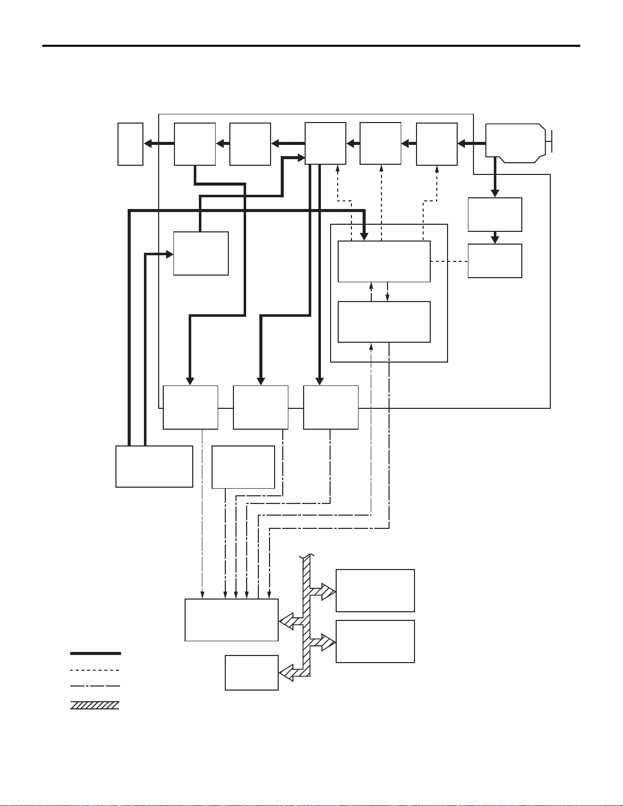
SYSTEM CONFIGURATION
ACD03944
Belt &
pulley
AB
Wheel
Reduction
gear
Engine
Forward/
reverse
switching
mechanism
Torque
converter
Sprocket & chain
Oil pump
Hydraulic control
system
Turbine
speed
sensor
Control device Inhibitor switch
CVT-ECU
ABS/ASC-ECU
Engine-ECU
Parking
mechanism
<In transmission>
<In valve body>
: Mechanical system
: CAN communication
ETACSECU
Differential
gear
Electronic control
system
Secondary
pulley speed
sensor
: Oil pressure system
: Electrical system
Primary
pulley speed
sensor
CVT
GENERAL INFORMATION
23A-3
Page 46

23A-4
ACD03886
CVT fluid
cooler
Inhibitor switch
AB
Secondary pulley
speed sensor
Primary pulley
speed sensor
CVT fluid filter
Turbine speed
sensor
OVERVIEW
CVT
GENERAL INFORMATION
Page 47

CVT
ACD03942
AB
1
2
3
4
5
6
7
8
9
10
11
12
13
14
15
16
17
18
19
20
21
22
23
GENERAL INFORMATION
DESCRIPTION OF STRUCTURE AND OPERATION
SECTIONAL VIEW
23A-5
1. Converter housing
2. Driven sprocket
3. Chain
4. Reverse brake
5. Oil pump
6. Forward clutch
7. Planet carrier
8. Primary pulley
9. Sun gear
10. Steel belt
11. Side cover
12. Internal gear
13. Parking gear
14. Secondary pulley
15. Final ge ar
16. Differential case
Page 48

23A-6
ACD03885
AB
CVTECU
Primary pulley
speed
CVT fluid
temperature
Lubricating and
cooling systems
Torque
converter
engage
Oil pump
Primary pulley
Secondary pulley
Forward clutch
Reverse brake
Manual valve
Primary reducing
valve
Valve body
Mechanical system
Oil pressure system
Electrical system
Pressure
regulator valve
Torque converter
regulator valve
Lock-up
control valve
Lock-up
solenoid valve
Inhibitor
switch
Engine
speed
Secondary
pulley speed
Throttle
opening
Secondary pressure
solenoid valve
Primary pressure
solenoid valve
Pilot valve A
Input signals
Secondary
pressure
Torque
converter
release
Primary
pressure
Turbine
speed
Line pressure
solenoid valve
Select solenoid valve
Pilot valve B
Secondary
reducing valve
GENERAL INFORMATION
17. Idler ge ar
18. Reduction gear
19. Taper roller bearing
20. Output gear
21. Drive sprocket
22. Input shaft
23. Torque converter
HYDRAULIC CONTROL SYSTEM
CONTROL DESCRIPTION
The hydraulic control mechanism is comprised of the
vane-type oil pump driven by the engine via the oil
pump drive chain, the hydraulic control valve which
controls the line pressure and shift change, and the
input signal system.
CVT
Page 49

CVT
GENERAL INFORMATION
23A-7
GENERAL INFORMATION REGARDING THE MAIN COMPONENTS
Component Function
Manual valve Distributes the clutch operating pressure to each circuit,
depending on each selector lever position.
Lock-up control valve Regulates the engagement pressure and disengagement
pressure of the torque converter.
Torque converter regulator valve Regulates the supply pressure to the torque converter to the
optimal pressure for the driving conditions.
Pressure regulator valve Regulates the discharge pressure from the oil pump to the
optimal pressure (line pressure) for the driving conditions.
Secondary reducing valve Reduces the line pressure to regulate the secondary pressure.
Primary reducing valve Reduces the line pressure to regulate the primary pressure.
Pilot valve A Reduces the line pressure to regulate the operation pressures
of the solenoid valves below:
• Primary pressure solenoid valve
• Secondary pressure solenoid valve
• Line pressure solenoid val ve
• Select solenoid valve
Pilot valve B Reduces fluid pressure delivered from pilot valve A to regulate
the operation pressure of the lock-up solenoid valve.
Line pressure solenoid valve Controls the pressure regulator valve.
Primary pressure solenoid valve Controls the primary reducing valve.
Secondary pressure solenoid valve Controls the secondary reducing valve.
Lock-up solenoid valve Controls the lock-up control valve.
Select solenoid valve Regulates the forward clutch pressure and reverse brake
pressure.
Page 50

23A-8
ACD03887
AB
Line pressure
Primary pulley
Secondary pulley
Primary reducing
valve
Secondary
reducing valve
SHIFT MECHANISM
Pulley ratio
CVT
GENERAL INFORMATION
The system applies the primary pressure, which is
regulated by the primary reducing valve, to the pri
mary pulley and the secondary pressure, which is
regulated by the secondary reducing valve, to the
secondary pulley, respectively. Pulley ratio depends
on these pressures.
-
Page 51

CVT
ACD03888
Line pressure
solenoid valve
: Electrical system
: CAN communication
Line pressure
control
Inhibitor switch signal
Turbine speed sensor
CVT fluid temperature
sensor
Secondary pulley
speed sensor
Primary pulley speed
Primary pulley
speed sensor
CVT fluid temperature
Secondary pulley speed
Secondary pressure
sensor
Secondary hydraulic pressure
Turbine speed
CVT-ECU
·
Accelerator opening angle
signal
·
Engine speed signal
·
Engine torque signal
·
Stop lamp switch signal
·
Sport mode signal
AB
: Oil pressure system
Pressure
regulator valve
Secondary
pressure
control
Secondary pressure
solenoid valve
Secondary
reducing valve
Primary pressure
sensor
Primary hydraulic pressure
GENERAL INFORMATION
LINE PRESSURE CONTROL AND SECONDARY PRESSURE CONTROL
23A-9
The high-precision line pressure control and secondary pressure control have reduced the friction for better fuel economy.
Page 52

23A-10
ACD03889
Lock-up
solenoid valve
: Electrical system
: CAN communication
Lock-up
control
Inhibitor switch signal
Turbine speed sensor
CVT fluid temperature
sensor
Secondary pulley
speed sensor
Primary pulley speed
Primary pulley
speed sensor
CVT fluid temperature
Secondary pulley speed
Secondary pressure
sensor
Secondary hydraulic pressure
Turbine speed
CVT-ECU
AB
: Oil pressure system
Lock-up pressure
control valve
·
Accelerator opening angle
signal
·
Engine speed signal
·
Engine torque signal
·
Stop lamp switch signal
·
Sport mode signal
Primary pressure
sensor
Primary hydraulic pressure
LOCK-UP CONTROL
CVT
GENERAL INFORMATION
• The system engages the lock-up clutch in the
torque converter to eliminate slips in the torque
converter. This improves the transmission effi
ciency. The slip in the lock-up clutch is controlled
optimally, thus allowing a comfortable driving.
-
• The lock up control valve is controlled by the
lock-up pressure solenoid valve, and the lock-up
solenoid valve is controlled by the signal from the
CVT-ECU. The lock up control valve sets the
lock-up clutch into a state of engagement, or dis
engagement.
• It inhibits lock-up operation when the fluid temperature is low.
-
Page 53

SELECT CONTROL
ACD03890
Line pressure
solenoid valve
: Electrical system
: CAN communication
Select
control
Inhibitor switch signal
Turbine speed sensor
CVT fluid temperature
sensor
Secondary pulley
speed sensor
Primary pulley speed
Primary pulley
speed sensor
CVT fluid temperature
Secondary pulley speed
Secondary pressure
sensor
Secondary hydraulic pressure
Turbine speed
CVT-ECU
AB
Select solenoid valve
·
Accelerator opening angle
signal
·
Engine speed signal
·
Engine torque signal
·
Stop lamp switch signal
Primary pressure
sensor
Primary hydraulic pressure
CVT
GENERAL INFORMATION
23A-11
When an operation of N → D or P → R range is performed, the optimal operating pressure is set based
on the accelerator angle, engine speed, primary pul
ley speed, secondary pulley speed and turbine
speed to reduce the shock caused by shifting.
-
Page 54

23A-12
GENERAL INFORMATION
CONTROL ELEMENTS AND INPUT/OUTPUT
Item Input/output signal Control
Shift
control
CVT
Line
pressure
control
Select
control
Lock-up
control
Fail-safe
function*
Input Engine torque signal
Engine speed signal
Throttle position signal
Idle signal
Stop lamp switch signal
Primary pressure sensor
Secondary pressure sensor
CVT fluid temperature sensor
Turbine speed sensor
Primary pulley speed sensor
Secondary pulley speed sensor
Inhibitor switch
Shift switch assembly
Output Line pressure solenoid valve
Primary pressure solenoid valve
Lock-up solenoid valve
Secondary pressure solenoid valve
× × × × ×
× × × × ×
× × × × −
× × − × −
× × × × −
− × − − ×
× × − − ×
× × × × ×
× × × × ×
× × × × ×
× × − × ×
× × × × ×
× × − × −
× × × − ×
× × − − ×
− − − × ×
× × − − ×
Select solenoid valve
Selector lever position display
NOTE: *: If an abnormal input/output signal is generated, the CVT-ECU will trigger a fail-safe function.
× − × − ×
− − × − −
Page 55

CVT
GENERAL INFORMATION
23A-13
FAIL-SAFE FUNCTION
If abnormality occurs in signals from various sensors,
switches, or solenoids, this function allows control
ling them with the minimum adverse effect to the
driving performance.
-
PROTECTION CONTROL
General
• If the CVT-ECU or the transmission may be damaged or deteriorated, the CVT-ECU will be protected temporarily for safety. If a safety can be obtained again, the system will resume normal operation.
• The CVT-ECU has the protection functions as below:
Control during wheel spinning
Item Contents
Control content When the system detects a wheel spinning, it will restrict engine performance and
pulley ratio to increase line pressure. The clutch pressure is also increased.
Vehicle behaviour
during control
Resume condition The system resumes normal operation when wheel spinning is eliminated.
The engine speed and the vehicle speed will not be increased although the driver
continues to depress the accelerator pedal during a wheel spinning.
Control at high oil temperature
Item Contents
Control content When the CVT fluid temperature rises, the system will decrease the maximum
permissible shifting speed and torque to avoid overheat.
Vehicle behaviour
during control
Resume condition Resumes normal operation when the CVT fluid temperature drops.
Torque reduction when the vehicle is reversing
Item Contents
Control content The system restricts the engine performance in accordance with vehicle speed when
Vehicle behaviour
during control
Resume condition Resumes normal operation when the selector lever is moved from R range to
Reversing prevention
Item Contents
Control content The system will deactivate the reverse brake when the selector lever is moved to R
Vehicle behaviour
during control
Resume condition Resumes normal operation when the vehicle is driven at lower speed. (The system
Note that driving performance may be deteriorated.
the vehicle is reversing.
Driving performance may be deteriorated.
another.
range while driving forwards at a certain speed.
The transmission will remain at neutral range although the driver moves the selector
lever to R range while the vehicle is driven forwards.
engages the reverse brake)
Page 56

23A-14
SERVICE SPECIFICATIONS
CVT
SERVICE SPECIFICATIONS
M1231200300740
Item Standard value
CVT fluid temperature sensor resistance kΩ at 20°C 6.29 − 6.83
at 50°C 2.10 − 2.25
at 80°C 0.85 − 0.90
Line pressure solenoid valve coil resistance Ω • 5.5 − 7.0 (fluid temperature:
20
Primary pressure solenoid valve coil resistance Ω
Secondary pressure solenoid valve coil resistance Ω
Select solenoid valve coil resistance Ω
Lock-up solenoid valve coil resistance Ω
Engine stall speed r/min D range 2,400 − 2,900
R range 2,400 − 2,900
°C)
• 6.0 − 8.0 (fluid temperature:
°C)
50
• 6.5 − 8.5 (fluid temperature:
°C)
80
LUBRICANTS
Item Brand name Capacity L
CVT fluid MITSUBISHI MOTORS GENUINE CVTF-J4 6.9
M1231200400907
Page 57

CVT
ACB05421
MB992745
MB992746
MB992744
MB992747
MB992748
a
b
c
d
e
DO NOT USE
AB
SPECIAL TOOLS
SPECIAL TOOLS
Tool Number Name Use
a.MB992744
b.MB992745
c. MB992746
d.MB992747
e.MB992748
a.Vehicle
communication
interface-Lite
(V.C.I.-Lite)
b.V.C.I.-Lite main
harness A (for
vehicles with
CAN
communication)
c. V.C.I.-Lite main
harness B (for
vehicles without
CAN
communication)
d.V.C.I.-Lite USB
cable short
e.V.C.I.-Lite USB
cable long
CVT check (M.U.T.-III diagnosis
code display and service data
display)
23A-15
M1231200600752
Page 58

23A-16
CAUTION
MB991910
MB991826
MB991955
MB991911
MB991824
MB991827
MB991825
a
b
c
d
e
f
DO NOT USE
MB992006
AC103525
A
a
CVT
SPECIAL TOOLS
Tool Number Name Use
MB991955
a: MB991824
b: MB991827
c: MB991910
d: MB991911
e: MB991825
f: MB991826
M.U.T.-III
sub-assembly
a: Vehicle
communication
interface (V.C.I.)
b: USB cable
c: M.U.T.-III main
harness A
(applicable to
vehicles with
CAN
communication)
For vehicles with CAN
communication, use the M.U.T .-III
main harness A to send the
simulated vehicle speed. If you
connect the M.U.T.-III main
harness B instead, the CAN
communication does not
function correctly.
CVT check (M.U.T.-III diagnosis
code display and service data
display)
d: M.U.T.-III main
harness B
(applicable to
vehicles without
CAN
communication)
e: Measurement
adapter
f: Trigger harness
MB992006 Extra fine probe Continuity check and voltage
measurement at harness wire or
connector
MD998330
a: MD998331
Oil pressure gauge
(3.0 MPa)
Hydraulic pressure measurement
a: Joint
MB992127 Joint
Page 59

CVT
B991454
B991527
MB992906
Z203830
B992853
SPECIAL TOOLS
Tool Number Name Use
MB992075 Handle Use with oil seal installer
MB992140 Oil seal installer Installation of side oil seal
MB992206 Oil seal installer Installation of side oil seal <2WD>
23A-17
MB991454 Engine hanger
balancer
MB991527 Engine hanger
MB992906 Engine hanger
attachment
MB991895 Engine hanger
Engine assembly support during
automatic transmission assembly
removal and installation {For the
engine hanger balancer
(MB991454), use chains only.}
NOTE: Engine hanger balancer
(MB991454) is a part of the engine
hanger assembly (MB991453).
MB992853 Engine hanger plate
Page 60

23A-18
ACD04025
1XG3C
Y13317653
Serial number (A)
1XG3C Y317653
Serial number (M.U.T.-III Display)
Part number
Factory code
Year
Month
Number
Part number
Factory code
Number
Month
AB
A
CVT
TROUBLESHOOTING
TROUBLESHOOTING
INITIALISATION PROCEDURE FOR CVT LEARNED VALUE
M1231202400419
PURPOSE
After the CVT assembly and the valve body assembly are replaced, their serial number and learned
value must be initialised. The initialisation procedure
is as below.
INITIALISATION PROCEDURE
1. Move the selector lever to the P range and turn
the ignition switch to the "LOCK" (OFF) position.
Then, connect M.U.T.-III to the diagnosis
connector.
2. Turn the ignition switch to the "ON" position, and
then move the selector lever to the R range.
3. Depress the accelerator pedal while depressing
the brake pedal. (Engine stops.) Use the M.U.T.-III
special function to execute "Reset (item No.1:
Control learning value)" while holding them in
applied position.
4. Set the selector lever to the P range.
5. Turn the ignition switch to the "LOCK" (OFF)
position, and then wait for ten seconds.
6. Turn the ignition switch to the "ON" position.
Execute the special function "CVT oil degradation
level (item No.1: Clear CVT oil degradation level)"
on the M.U.T.-III to delete a CVT fluid
deterioration level.
WHEN REPLACING THE CVT-ECU
1. Turn the ignition switch to the "LOCK" (OFF)
position. Then, connect M.U.T.-III to the diagnosis
connector.
2. Turn the ignition switch to the "ON" position.
3. Execute the special function "Write calibration
value (Calibration value Read&save)" on the
M.U.T.-III to read a serial number which is stored
in the CVT-ECU.
LEARNING PROCEDURE
When the CVT-ECU, the CVT assembly or the valve
body assembly is replaced, adopt the system by
using the M.U.T.-III.
M1231224400019
4. Make sure that the read serial number
corresponds with the one stamped on the CVT
assembly (see illustration).
NOTE: If it does not correspond, observe the following procedure.
.
Page 61

a.
ACD04026
1XG3C Y317653
Serial number (M.U.T.-III Display)
Part number
Factory code
Number
Y317653 - 13
Serial number (B)
Factory code
Year
Month
Number
Month
1XG3C
Serial number (A)
Part number
AB
B
A
a. Remove the oil pan (refer to P.23A-90), and
check the serial number of the valve body
assembly shown in the illustration.
b. If no serial number is stamped on the valve
body assembly, import data from the server to
the M.U.T.-III according to the serial number
on the CVT assembly.
c. If a serial number is stamped on the valve
body assembly , ma ke sure that the read serial
number corresponds with the one stamped on
the valve body assembly (see illustration).
YES: Store the serial number in the M.U.T.-III.
NO: Import data from the server to the M.U.T.-III
according to the serial number on the valve
body assembly.
5. Store the serial number in the M.U.T.-III.
NOTE: Be sure to write down the serial number.
The serial number will be needed to compare it
with the number imported into the M.U.T .-III and to
select the number.
6. Turn the ignition switch to the "LOCK" (OFF)
position.
CVT
TROUBLESHOOTING
7. Remove the CVT-ECU and install a new
CVT-ECU (Refer to
8. Turn the ignition switch to the "ON" position.
9. Make sure that the selector lever is in the P or N
range and that P or N is not displayed on the
combination meter.
10.Execute the special function "Write calibration
value (Saved calibration value writing)" on the
M.U.T.-III to write the serial number into the ECU.
1 1.The shift range symbol (P or N) in the combination
meter should illuminate.
NOTE: If the shift range symbol (P or N) in the
combination meter does not illuminate, observe
the following procedure.
.
a. Move the selector lever to the R range.
b. Depress the accelerator pedal while depress-
ing the brake pedal. (Engine stops.) Use the
M.U.T.-III special function to execute "Calibra
tion value reset (item No.1: Calibration value
reset)" while holding them in applied position.
c. Set the selector lever to the P range.
d. Turn the ignition switch to the "LOCK" (OFF)
position, and then wait for ten seconds.
e. Repeat from Step 2.
12.Make sure that the serial number on "Saved
calibration value writing" completion screen
corresponds with the serial number of the CVT
assembly (or the valve body assembly) that was
written down earlier.
NOTE: If it does not correspond, observe the following procedure.
.
a. Move the selector lever to the R range.
b. Depress the accelerator pedal while depress-
ing the brake pedal. (Engine stops.) Use the
M.U.T.-III special function to execute "Calibra
tion value reset (item No.1: Calibration value
reset)" while holding them in applied position.
c. Set the selector lever to the P range.
d. Turn the ignition switch to the "LOCK" (OFF)
position, and then wait for ten seconds.
e. Repeat from Step 10.
13.Turn the ignition switch to the "LOCK" (OFF)
position.
23A-19
P.23A-100).
-
-
Page 62

23A-20
ACD04377
1XG3C
Y13317653
Serial number (CVT assembly)
1XG3C Y317653
Serial number (CD-R)
FKK_IP_INF_3VX0D_Y200733_130301
File name (M.U.T.-III Display)
FKK_IP_INF_1XG3C_Y317653_130329
AB
CVT
TROUBLESHOOTING
14.Observe the operations below:
a. Wait until the engine is warmed up. Then road
test the vehicle for approx. one minute at 40 km/h
or more. Consequently , check whether the CVT is
in the following conditions.
• No CVT-related diagnosis code is set.
• A diagnosis code is set, but you cannot iden-
tify any trouble symptoms (e.g. abnormal
noise)
• There is no fluid leak.
b. Start the engine.
c. Teach the system a meeting point. All of the fol-
lowing conditions must be satisfied for approximately 90 seconds.
• The vehicle is stationary.
• Engine speed: 500 − 850 r/min (Idling)
• Brake pedal: Depress
• Accelerator pedal: Release
• Selector lever position: D
• Transmission fluid temperature: 40 − 100°C
d. Turn the ignition switch to the "LOCK" (OFF)
position.
15.Operation complete.
6. Move the selector lever to the R range.
7. Depress the accelerator pedal while depressing
the brake pedal. (Engine stops.) Use the M.U.T.-III
special function to execute "Calibration value
reset (item No.1: Calibration value reset)" while
holding them in applied position.
8. Set the selector lever to the P range.
9. Turn the ignition switch to the "LOCK" (OFF)
position, and then wait for ten seconds.
10.Turn the ignition switch to the "ON" position.
11.Make sure that the selector lever is in the P or N
range and that P or N is not displayed on the
combination meter.
WHEN REPLACING THE CVT ASSEMBLY
1. Note the serial number, which is stamped on the
new CVT assembly.
2. Remove the CVT assembly and install a new CVT
assembly.
3. Connect M.U.T.-III to the diagnosis connector.
4. Turn the ignition switch to the "ON" position.
5. Import a serial number from the CD-R*, which is
supplied with a new CVT assembly, into the
M.U.T.-III.
NOTE: *: Follow the steps below to import a serial
number from the CD-R into the M.U.T.-III.
.
1. Select "Special function."
2. Select "Write calibration value."
3. Select "Saved calibration value writing."
4. Press the "File import" button.
5. Select an appropriate removable disc.
6. Confirm that "Completed." is displayed.
12.Select the same file name (shown in the
illustration) as the serial number of CD-R or CVT
assembly on the special function "Write
calibration value (Saved calibration value writing)"
screen and import the serial number into the
M.U.T.-III.
13.The shift range symbol (P or N) in the
combination meter should illuminate.
NOTE: If the shift range symbol (P or N) in the
combination meter does not illuminate, repeat the
operations from step 5.
Page 63

TROUBLESHOOTING
ACD04025
1XG3C
Y13317653
Serial number (A)
1XG3C Y317653
Serial number (M.U.T.-III Display)
Part number
Factory code
Year
Month
Number
Part number
Factory code
Number
Month
AB
A
14.Make sure that the serial number on "Saved
calibration value writing" completion screen
corresponds with the serial number of the new
CVT assembly (see illustration) that was written
down earlier.
NOTE: If it does not correspond, repeat the operations from step 5.
15.Turn the ignition switch to the "LOCK" (OFF)
position.
16.Observe the operations below:
a. Wait until the engine is warmed up. Then road
test the vehicle for approx. one minute at 40 km/h
or more. Consequently , check whether the CVT is
in the following conditions.
• No CVT-related diagnosis code is set.
• A diagnosis code is set, but you cannot iden-
tify any trouble symptoms (e.g. abnormal
noise)
• There is no fluid leak.
b. Start the engine.
CVT
23A-21
c. Teach the system a meeting point. All of the fol-
lowing conditions must be satisfied for approximately 90 seconds.
• The vehicle is stationary.
• Engine speed: 500 − 850 r/min (Idling)
• Brake pedal: Depress
• Accelerator pedal: Release
• Selector lever position: D
• Transmission fluid temperature: 40 − 100°C
d. Turn the ignition switch to the "LOCK" (OFF)
position.
17.Turn the ignition switch to the "ON" position.
18.Execute the special function "CVT oil degradation
level (item No.1: Clear CVT oil degradation level)"
on the M.U.T.-III to delete a CVT fluid
deterioration level.
19.Operation complete.
WHEN REPLACING THE VALVE BODY
ASSEMBLY
1. Note the serial number, which is stamped on the
new valve body assembly.
2. Remove the valve body assembly and install a
new valve body assembly.
3. Connect M.U.T.-III to the diagnosis connector.
4. Turn the ignition switch to the "ON" position.
5. Import a serial number from the CD-R*, which is
supplied with a new valve body assembly, into the
M.U.T.-III.
NOTE: *: Follow the steps below to import a ser ial
number from the CD-R into the M.U.T.-III.
.
1. Select "Special function."
2. Select "Write calibration value."
3. Select "Saved calibration value writing."
4. Press the "File import" button.
5. Select an appropriate removable disc.
6. Confirm that "Completed." is displayed.
6. Move the selector lever to the R range.
7. Depress the accelerator pedal while depressing
the brake pedal. (Engine stops.) Use the M.U.T.-III
special function to execute "Calibration value
reset (item No.1: Calibration value reset)" while
holding them in applied position.
8. Set the selector lever to the P range.
9. Turn the ignition switch to the "LOCK" (OFF)
position, and then wait for ten seconds.
10.Turn the ignition switch to the "ON" position.
Page 64

23A-22
ACD04377
Serial number (Valve body assembly)
1XG3C Y317653
Serial number (CD-R)
FKK_IP_INF_3VX0D_Y200733_130301
File name (M.U.T.-III Display)
FKK_IP_INF_1XG3C_Y317653_130329
AC
Y317653 - 131XG3C
ACD04026
1XG3C Y317653
Serial number (M.U.T.-III Display)
Part number
Factory code
Number
Y317653 - 13
Serial number (B)
Factory code
Year
Month
Number
Month
1XG3C
Serial number (A)
Part number
AB
B
A
CVT
TROUBLESHOOTING
11.Make sure that the selector lever is in the P or N
range and that P or N is not displayed on the
combination meter.
12.Select the same file name (shown in the
illustration) as the serial number of CD-R or valve
body assembly on the special function "Write
calibration value (Saved calibration value writing)"
screen and import the serial number into the
M.U.T.-III.
13.The shift range symbol (P or N) in the
combination meter should illuminate.
NOTE: If the shift range symbol (P or N) in the
combination meter does not illuminate, repeat the
operations from step 5.
14.Make sure that the serial number on "Saved
calibration value writing" completion screen
corresponds with the serial number of the new
valve body assembly (see illustration) that was
written down earlier.
NOTE: If it does not correspond, repeat the operations from step 5.
15.Turn the ignition switch to the "LOCK" (OFF)
position, and then wait for ten seconds.
16.Set the vehicle to the following condition.
• The vehicle is stationary.
• Engine speed: 500 − 850 r/min (Idling)
• Brake pedal: Depress
• Air conditioner: OFF
• Accelerator pedal: Release
• Selector lever position: N
• CVT fluid temperature: 50 − 100°C
17.Depress and hold the brake pedal fully to secure
the vehicle against rolling away, and execute the
special function "Control valve learning mode
(item No.1: Control valve learning mode)" on the
M.U.T.-III.
18.Move the selector lever to the "D" position, and
confirm that "Completed." is displayed on the
M.U.T.-III screen after 60 seconds.
NOTE: If "Complete" is not displayed on the
M.U.T.-III within 60 seconds, move back the
selector lever to N range. Then execute the item
No.1; Control valve learning mode again.
19.Shift the selector lever to P position.
20.Turn the ignition switch to the "LOCK" (OFF)
position, and then wait for ten seconds.
21.Set the vehicle to the following condition.
• The vehicle is stationary.
• Engine speed: 500 − 850 r/min (Idling)
• Brake pedal: Depress
• Air conditioner: OFF
• Accelerator pedal: Release
• Selector lever position: N
• CVT fluid temperature: 50 − 100°C
22.Depress and hold the brake pedal fully to secure
the vehicle against rolling away, and execute the
special function "Control valve learning mode
(item No.1: Control valve learning mode)" on the
M.U.T.-III.
Page 65

CVT
ACC00131
AB
(A)
(B)
<High contrast meter>
TROUBLESHOOTING
23A-23
23.Move the selector lever to the "R" position, and
confirm that "Completed." is displayed on the
M.U.T.-III screen after 60 seconds.
NOTE: If "Complete" is not displayed on the
M.U.T.-III within 60 seconds, move back the
selector lever to N range. Then execute the item
No.1; Control valve learning mode again.
24.Shift the selector lever to P position.
25.Turn the ignition switch to the "LOCK" (OFF)
position, and then wait for ten seconds.
26.Observe the operations below:
a. Wait until the engine is warmed up. Then road
test the vehicle for approx. one minute at 40 km/h
or more. Consequently , check whether the CVT is
in the following conditions.
• No CVT-related diagnosis code is set.
• A diagnosis code is set, but you cannot iden-
tify any trouble symptoms (e.g. abnormal
noise)
• There is no fluid leak.
b. Start the engine.
c. Teach the system a meeting point. All of the fol-
lowing conditions must be satisfied for approximately 90 seconds.
• The vehicle is stationary.
• Engine speed: 500 − 850 r/min (Idling)
• Brake pedal: Depress
• Accelerator pedal: Release
• Selector lever position: D
• Transmission fluid temperature: 40 − 100°C
d. Turn the ignition switch to the "LOCK" (OFF)
position.
27.Turn the ignition switch to the "ON" position.
28.Execute the special function "CVT oil degradation
level (item No.1: Clear CVT oil degradation level)"
on the M.U.T.-III to delete a CVT fluid
deterioration level.
29.Operation complete.
FLUID DETERIORA TION LEVEL ERASING PROCEDURE
M1231224500016
1. Turn the ignition switch to the "LOCK" (OFF)
position. Then, connect M.U.T.-III to the diagnosis
connector.
2. Turn the ignition switch to the "ON" position.
3. Use the M.U.T.-III special function to execute
"CVT oil degradation level (item No.1: Clear CVT
oil degradation level)".
4. Turn the ignition switch to the "LOCK" (OFF)
position.
DIAGNOSTIC FUNCTION
M1231219000480
WARNING INDICATOR
When any malfunction occurs in the items related to
the CVT system, which are described below, the
symbol (A) continues being displayed in the informa
tion screen in the multi information display.
Check if the diagnosis code is set when the symbol
(A) continues being displayed in the information
screen in the multi information display.
NOTE: When the symbol (B) is displayed in the information screen in the multi information display, the
CVT fluid temperature is high. (Symbol (B) is turned
on when the fluid temperature is approximately
138
°
C or higher and turned off automatically when
the fluid temperature drops below approximately
135
°
C.)
-
Page 66

23A-24
ROAD TEST
Steps Conditions
for
test/operation
1 Ignition switch:
LOCK (OFF)
CVT
TROUBLESHOOTING
Test/Operation Judgement
standard
Ignition switch
(1) ON
Data list No.6
(1) System voltage
Check
item
ECU
power
supply
Diagnosis
code No.
−
M1231207800672
Checking
procedure in
case of error
Malfunction of
CVT-ECU
power supply
system
2 Ignition switch:
ON
Engine:
Stopped
Selector lever
position
(1) P
(2) R
(3) N
(4) D
(5) Ds <Vehicles
without paddle
shift>
(6) L
Data list No.7
(1) System voltage
The relevant
diagnosis code is not
detected.
The relevant
diagnosis code is not
detected.
Data list No.72
(1) P, (2) R (3) N (4)
D (5) Ds/L (6) Ds/L
Data list No.60
(1) ON (2) OFF
(3) OFF (4) OFF
(5) OFF (6) OFF
Data list No.61
(1) OFF (2) ON
(3) OFF (4) OFF
(5) OFF (6) OFF
Data list No.62
(1) OFF (2) OFF
(3) ON (4) OFF
(5) OFF (6) OFF
Solenoid
supply
voltage
Variant
coding
EEPROM P1637 Malfunction of
Inhibitor
switch
P1607 Malfunction of
system power
supply
U1197,
U1195,
U1417
P0705 Malfunction of
Malfunction of
the coding
memory backup
inhibitor switch
Data list No.63
(1) OFF (2) OFF
(3) OFF (4) ON
(5) OFF (6) OFF
Data list No.64
(1) OFF (2) OFF
(3) OFF (4) OFF
(5) ON (6) ON
Data list No.58
(1) OFF (2) OFF
(3) OFF (4) OFF
(5) ON (6) ON
Ds
position
switch
P071B Malfunction of
Ds position
switch
Page 67

CVT
TROUBLESHOOTING
23A-25
Steps Conditions
for
test/operation
2 Ignition switch:
ON
Engine:
Stopped
3 Ignition switch:
ON
Engine:
Stopped
Selector lever
position: P
4 Ignition switch:
START
5 Engine
warming up
Test/Operation Judgement
standard
Paddle shift lever
position
(1) Pull the paddle
shift (+) (right side)
toward you and
hold.
(2) Release the
lever
Paddle shift lever
position
(1) Pull the paddle
shift (-) (left side)
toward you and
hold.
(2) Release the
lever
Accelerator pedal
(1) Fully closed
(2) Depressed
(3) Fully opened
Brake pedal
(1) Depressed
(2) Released
Perform the
starting test in the
P or N position
Drive the vehicle
for 15 minutes or
more to raise the
CVT fluid
temperature to 45
to 100
°C
Data list No.67
(1) ON
(2) OFF
Data list No.68
(1) ON
(2) OFF
Data list No.15
(1) 0%
(2) Gradually
increases from (1)
(3) 100%
Data list No.59
(1) ON
(2) OFF
Engine can be
started
Data list No.5
Voltage drops
gradually
Data list No.22
Fluid temperature
rises gradually
Check
item
Paddle
shift UP
switch
Paddle
shift
DOWN
switch
APS
Stop lamp
switch
− −
CVT fluid
temperatu
re sensor
Diagnosis
code No.
P0815 Malfunction of
P0816
− −
P0703 Malfunction of
P0712,
P0713
Checking
procedure in
case of error
paddle shift
switch
stop lamp
switch
Malfunction of
engine system
Malfunction of
CVT fluid
temperature
sensor
The relevant
diagnosis code is not
detected.
The relevant
diagnosis code is not
detected.
The relevant
diagnosis code is not
detected.
The relevant
diagnosis code is not
detected.
P0711
G sensor P1798 Malfunction of
G sensor
Brake fluid
pressure
sensor
ABS/ASC P1773 Malfunction of
P1799 Malfunction of
brake fluid
pressure signal
ABS/ASC
Page 68

23A-26
CVT
TROUBLESHOOTING
Steps Conditions
for
test/operation
6 Engine: Idling Selector lever
Test/Operation Judgement
position: P
Accelerator pedal:
Fully closed
Selector lever
position: N
standard
Data list No.11
600 to 900 r/min
Data list No.42
0 to 0.8 A
Data list No.2
0.2 to 0.7 V
Data list No.3
1.4 to 1.9 V
Data list No.46
0 to 0.8 A
Data list No.21
1.0 to 1.2 MPa
Data list No.48
Approx. 1.0 A
Check
item
Engine
revolution
Line
pressure
solenoid
valve
Primary
pressure
sensor
Secondar
y pressure
sensor
Secondar
y pressure
solenoid
valve
Select
pressure
solenoid
valve
Diagnosis
code No.
−
P0962,
P0963
P0847,
P0848
P0842,
P0843
P0776,
P0966,
P0967
P2720,
P2721
Checking
procedure in
case of error
Malfunction of
engine system
Malfunction of
line pressure
solenoid valve
Malfunction of
primary
pressure
sensor
Malfunction of
secondary
pressure
sensor
Malfunction of
secondary
pressure
solenoid valve
Malfunction of
select pressure
solenoid valve
Page 69

CVT
TROUBLESHOOTING
23A-27
Steps Conditions
for
test/operation
7 Selector lever
position: D
Test/Operation Judgement
standard
Stop the vehicle
(depress the brake
pedal)
During driving (at
approx. 20 km/h)
Data list No.13
Pulley gear ratio: less
than 2.62
Data list No.48
0.6 to 0.9 A
(The displayed value
is different from the
one for N range)
Data list No.20
0.2 to 0.6 MPa
Data list No.21
0.2 to 0.6 MPa
Data list No.44
0.7 to 0.9 A
Data list No.20
0.2 to 0.6 MPa
Check
item
Gear ratio P0730 Incorrect gear
Select
pressure
solenoid
valve
Primary
pressure
sensor
and
secondary
pressure
sensor
Primary
pressure
solenoid
valve
Diagnosis
code No.
P2720,
P2721
P084A Abnormality in
P0969,
P0970,
P0971
Checking
procedure in
case of error
ratio
Malfunction of
select pressure
solenoid valve
fluid pressure
sensor function
Malfunction of
primary
pressure
solenoid valve
Stop the vehicle,
and then
accelerate to 60
km/h on a level
road
Data list No.1
Speed detected:
more than 0 r/min
(nearly the same as
the turbine speed)
Data list No.40
0.4 to 0.6 A
Data list No.12
Amount of slippage:
less than 15 r/min
Data list No.8
Speed detected:
more than 0 r/min
(nearly the same as
the tachometer)
Data list No.10
Approx. 48 × Vehicle
speed (speedometer
display)
Data list No.13
Pulley gear ratio: 0.3
to 2.7
Primary
pulley
speed
sensor
Lock-up
solenoid
valve
Turbine
speed
sensor
Secondar
y speed
sensor
P0715 Malfunction of
primary pulley
speed sensor
P0741,
P2763,
P2764
P2765 Malfunction of
P0720 Malfunction of
Malfunction of
lock-up
solenoid valve
turbine speed
sensor
secondary
pulley speed
sensor
Page 70

23A-28
ACD04370
AB
OD
Low
Throttle opening 100%
Engine speed (r/min)
Vehicle speed (km/h)
0 100 15050
1,000
2,000
4,000
3,000
5,000
7,000
6,000
200
Throttle opening 50%
Throttle opening 75%
Throttle opening 0%
Throttle opening 25%
RATIO PATTERN
D RANGE
CVT
TROUBLESHOOTING
M1231202600792
Page 71

SPORT MODE
ACD04371
AB
0 100 15050
1,000
2,000
4,000
3,000
5,000
7,000
6,000
200
1st
gear
2nd
gear
3rd
gear
4th
gear
5th
gear
6th
gear
OD
Low
Engine speed (r/min)
Vehicle speed (km/h)
ACD04372
AB
Accelerator opening (%)
Vehicle speed (km/h)
0 100
25
50
100
75
20050 150
Disengaged
Lock-up
CVT
TROUBLESHOOTING
23A-29
DAMPER CLUTCH OPERATION ZONE
M1231204100663
Page 72

23A-30
CAUTION
TROUBLESHOOTING
CVT
DIAGNOSIS CODE CHART
M1231207901047
During diagnosis, a diagnosis code associated with other system may be set when the ignition switch
is turned on with connector(s) disconnected. On completion, confirm all systems for diagnosis
code(s). If diagnosis code(s) are set, erase them all.
Diagnosis
code No.
P0703 Malfunction of stop lamp switch
P0705 Malfunction of inhibitor switch
P071B Malfunction of Ds position switch <Vehicles without paddle shift>
P0711 Malfunction of CVT fluid temperature sensor (Abnormality in CVT fluid
P0712 Malfunction of CVT fluid temperature sensor (low input)
P0713 Malfunction of CVT fluid temperature sensor (high input)
P0715 Malfunction of primary pulley speed sensor
P0720 Malfunction of secondary pulley speed sensor
P0730 Incorrect gear ratio
P0741 Abnormality in lock-up function
P0776 Abnormality in secondary pressure solenoid valve function
P0815 Malfunction of paddle shift up switch <Vehicles with paddle shift>
P0816 Malfunction of paddle shift down switch <Vehicles with paddle shift>
P0842 Malfunction of secondary pressure sensor (low input)
P0843 Malfunction of secondary pressure sensor (high input)
Diagnostic item Reference
temperature sensor function)
page
P.23A-31
P.23A-32
P.23A-33
P.23A-33
P.23A-34
P.23A-34
P.23A-35
P.23A-36
P.23A-37
P.23A-38
P.23A-39
P.23A-40
P.23A-40
P.23A-41
P.23A-42
P0847 Malfunction of primary pressure sensor (low input)
P0848 Malfunction of primary pressure sensor (high input)
P084A Abnormality in fluid pressure sensor function
P0962 Malfunction of line pressure solenoid valve (low input)
P0963 Malfunction of line pressure solenoid valve (high input)
P0966 Malfunction of secondary pressure solenoid valve (low input)
P0967 Malfunction of secondary pressure solenoid valve (high input)
P0969 Abnormality in primary pressure solenoid valve function
P0970 Malfunction of primary pressure solenoid valve (low input)
P0971 Malfunction of primary pressure solenoid valve (high input)
P1607 Malfunction of system power supply (low voltage)
P1637 Malfunction of memory backup
P1773 Malfunction of ABS/ASC
P1798 Malfunction of G sensor signal
P1799 Malfunction of brake fluid pressure signal
P.23A-43
P.23A-44
P.23A-45
P.23A-46
P.23A-46
P.23A-47
P.23A-48
P.23A-49
P.23A-50
P.23A-50
P.23A-51
P.23A-52
P.23A-52
P.23A-53
P.23A-53
Page 73

CVT
TROUBLESHOOTING
23A-31
Diagnosis
code No.
P2719 Abnormality in select pressure solenoid valve function
P2720 Malfunction of select pressure solenoid valve (low input)
P2721 Malfunction of select pressure solenoid valve (high input)
P2763 Malfunction of lock-up solenoid valve (high input)
P2764 Malfunction of lock-up solenoid valve (low input)
P2765 Malfunction of turbine speed sensor
U0001 Malfunction of CAN communication circuit (Bus off)
U0100 CAN time-out error (Engine)
U0121 CAN time-out error (ABS/ASC)
U0141 CAN time-out error (ETACS)
U1197 Coding data unavailable
U1195 Coding not completed
U1417 Wrong coding data received
Diagnostic item Reference
page
P.23A-54
P.23A-55
P.23A-55
P.23A-56
P.23A-57
P.23A-58
P.23A-59
P.23A-59
P.23A-60
P.23A-60
P.23A-62
P.23A-61
P.23A-63
DIAGNOSIS CODE PROCEDURES
Code No. P0703: Malfunction of Stop Lamp Switch
DIAGNOSTIC FUNCTION
CVT-ECU detects malfunction using the stop lamp
switch signal sent from the ETACS-ECU.
JUDGEMENT CRITERIA
Drive the vehicle at 30 km/h or more for 10 seconds,
and then turn the ignition switch to the OFF position.
In this sequential operation, no variation has been
found in the stop lamp switch input signal in two con
secutive times.
PROBABLE CAUSES
• Malfunction of CAN bus line
• Malfunction of the stop lamp switch
• Damaged wiring harness and connectors
• Malfunction of CVT-ECU
• Malfunction of ETACS-ECU
-
DIAGNOSIS PROCEDURE
STEP 1. M.U.T.-III CAN bus diagnostics
Use M.U.T.-III to perform the CAN bus diagnosis.
Q: Is the check result normal?
YES : Go to Step 2
NO : Repair the CAN bus lines.
STEP 2. M.U.T.-III data list
Item 59: Brake switch
OK: The service data changes in response to
the brake operation.
Q: Is the check result normal?
YES : Go to Step 3
NO : Check the stop lamp switch circuit. (Refer to
GROUP 54A
Chart for Input Signal).
− ETACS, Trouble Symptom
STEP 3. Symptom recheck after erasing
diagnosis code
Q: Is the diagnosis code set?
YES : Replace CVT-ECU.
NO : Intermittent malfunction.
Page 74

23A-32
TROUBLESHOOTING
Code No. P0705: Malfunction of Inhibitor Switch
DIAGNOSTIC FUNCTION
CVT-ECU monitors the signal from the inhibitor
switch, and determines if the abnormal input is
present or not.
JUDGEMENT CRITERIA
• CVT-ECU does not detects the inhibitor switch
input signal when the vehicle speed is 3 km/h or
more for 10 seconds continuously.
• CVT-ECU detects the multiple inputs from the
inhibitor switch for 2 seconds.
PROBABLE CAUSES
• Malfunction of the inhibitor switch
• Improper adjustment of transmission control
cable
• Damaged wiring harness and connectors
• Malfunction of CVT-ECU
DIAGNOSIS PROCEDURE
STEP 1. Voltage measurement at inhib itor switch
connector (terminal No. 3)
(1) Disconnect the inhibitor switch connector, and
measure at the wiring harness side.
(2) Turn the ignition switch to the "ON" position.
(3) Measure the voltage between the inhibitor switch
connector (terminal No. 3) and body earth.
OK: 10 V or more
Q: Is the check result normal?
YES : Go to Step 2.
NO : Repair the connector(s) or the wiring
harness (power supply line between the
inhibitor switch connector terminal No. 3
and the ETACS-ECU connector).
STEP 2. Check for open circuit or short to earth
in INHP, INHR, INHN INHD and INHL line between
the inhibitor switch connector and the CVT-ECU
connector
Q: Is the check result normal?
YES : Go to Step 3.
NO : Repair the connector(s) or the wiring
harness.
CVT
STEP 3. Inhibitor switch and control cable
adjustment
Refer to P.23A-78.
Q: Is the check result normal?
YES : Go to Step 4.
NO : Adjust the inhibitor switch and the control
cable.
STEP 4. Inhibitor switch continuity check
Refer to P.23A-78.
Q: Is the check result normal?
YES : Go to Step 5.
NO : Replace the inhibitor switch (Refer to
P.23A-93.).
STEP 5. Voltage measurement at CVT-ECU
connector (INHP, INHR, INHN and INHD terminal)
(1) Connect the inhibitor switch connector.
(2) Disconnect the CVT-ECU connector, and
measure at the wiring harness side.
(3) Turn the ignition switch to the "ON" position.
(4) Measure the voltage at each terminal when the
selector lever is moved to each range.
• At P range: Between the CVT-ECU connector
(INHP terminal) and body earth
• At R range: Between the CVT-ECU connector
(INHR terminal) and body earth
• At N range: Between the CVT-ECU connector
(INHN terminal) and body earth
• At D range: Between the CVT-ECU connector
(INHD terminal) and body earth
• At L range: Between the CVT-ECU connector
(INHL terminal) and body earth
OK: 10 V or more
Q: Is the check result normal?
YES : Go to Step 6.
NO : Repair the connector(s) or the wiring
harness.
STEP 6. Symptom recheck after erasing
diagnosis code
Q: Is the diagnosis code set?
YES : Replace the CVT-ECU.
NO : Intermittent malfunction.
Page 75

CVT
TROUBLESHOOTING
Code No. P071B Malfunction of Ds position switch <Vehicles without paddle shift>
23A-33
DIAGNOSTIC FUNCTION
The CVT-ECU detects that the Ds position switch is
stuck to ON.
JUDGEMENT CRITERIA
The Ds position switch remains ON for five seconds
when the inhibitor switch is at "P", "R", or "N".
PROBABLE CAUSES
• Malfunction of Ds position switch
• Damaged wiring harness and connectors
• Malfunction of CVT-ECU
DIAGNOSIS PROCEDURE
STEP 1. M.U.T.-III data list
Item 58: Ds switch
OK: Turns ON when the selector lever is at
"Ds" or "L".
Q: Is the check result normal?
YES : Intermittent malfunction
NO : Go to Step 2.
STEP 2. Ds position switch single unit check
Q: Is the check result normal?
YES : Go to Step 3.
NO : Replace the selector lever assembly.
STEP 3. Check for short to earth in INHS line
between the CVT-ECU connector and the Ds
position switch connector
Q: Is the check result normal?
YES : Go to Step 4.
NO : Repair the connector(s) or wiring harness.
STEP 4. Check for open circuit in earth line
between the Ds position switch connector and
body earth.
Q: Is the check result normal?
YES : Go to Step 5.
NO : Repair the connector(s) or wiring harness.
STEP 5. Symptom recheck after erasing
diagnosis code
Q: Is the check result normal?
YES : Intermittent malfunction
NO : Replace CVT-ECU.
Code No. P071 1: Malfunction of CVT Fluid Temperature Sensor (Abnormality in CVT fluid temperature
sensor function)
DIAGNOSTIC FUNCTION
DIAGNOSIS PROCEDURE
CVT-ECU conducts fault detection by monitoring the
terminal voltage of the CVT fluid temperature sensor.
JUDGEMENT CRITERIA
The CVT fluid temperature does not reach 20°C af ter
the vehicle is driven for at least 15 minutes under the
following condition.
• Selector lever position: D
STEP 1. CVT fluid temperature sensor check
Refer to P.23A-82.
Q: Is the check result normal?
YES : Go to Step 2
NO : Replace the CVT fluid temperature sensor
(valve body harness). (Refer to
P.23A-90.).
• Vehicle speed: 50 km/h or more
• Accelerator opening angle: 12.5 % or more
• Engine speed: 450 r/min or more
PROBABLE CAUSES
• Malfunction of CVT fluid temperature sensor
• Damaged wiring harness and connectors
STEP 2. Symptom recheck after erasing
diagnosis code
Q: Is the diagnosis code set?
YES : Replace CVT-ECU.
NO : Intermittent malfunction.
• Malfunction of CVT-ECU
Page 76

23A-34
Code No. P0712: Malfunction of CVT Fluid Temperature Sensor (low input)
TROUBLESHOOTING
CVT
DIAGNOSTIC FUNCTION
CVT-ECU conducts fault detection by monitoring the
terminal voltage of the CVT fluid temperature sensor.
JUDGEMENT CRITERIA
CVT-ECU detects the fluid temperature 180°C or
more for 5 seconds.
PROBABLE CAUSES
• Malfunction of CVT fluid temperature sensor
• Damaged wiring harness and connectors
• Malfunction of CVT-ECU
DIAGNOSIS PROCEDURE
STEP 1. Check for short to earth in SPWR line
between the CVT assembly connector and the
CVT-ECU connector
Q: Is the check result normal?
YES : Go to Step 2
NO : Repair the connector(s) or the wiring
harness.
STEP 2. CVT fluid temperature sensor check
Refer to P.23A-82.
Q: Is the check result normal?
YES : Go to Step 3
NO : Replace the CVT fluid temperature sensor
(valve body harness). (Refer to
STEP 3. Symptom recheck after erasing
diagnosis code
Q: Is the diagnosis code set?
YES : Replace the CVT-ECU.
NO : Intermittent malfunction.
P.23A-90.).
Code No. P0713: Malfunction of CVT Fluid Temperature Sensor (high input)
DIAGNOSTIC FUNCTION
CVT-ECU conducts fault detection by monitoring the
terminal voltage of the CVT fluid temperature sensor.
JUDGEMENT CRITERIA
The CVT-ECU detect s the fluid temperat ure -40°C or
less for 5 seconds when the vehicle speed is 10km/h
or more.
PROBABLE CAUSES
• Malfunction of CVT fluid temperature sensor
• Damaged wiring harness and connectors
• Malfunction of CVT-ECU
DIAGNOSIS PROCEDURE
STEP 1. Check for open circuit in SPWR and
SGND line between the CVT assembly connector
and the CVT-ECU connector
Q: Is the check result normal?
YES : Go to Step 2
NO : Repair the connector(s) or the wiring
harness.
STEP 2. Voltage measurement at CVT-ECU
connector (SPWR terminal)
(1) Connect the CVT assembly connector and the
CVT-ECU connector.
(2) Turn the ignition switch to the "LOCK" (OFF)
position.
(3) Measure the CVT-ECU connector side by
backprobing.
(4) Measure the voltage between the CVT-ECU
connector SPWR terminal and body earth.
OK: 0 V
Q: Is the check result normal?
YES : Go to Step 3
NO : Repair the connector(s) or the wiring
harness.
Page 77

CVT
TROUBLESHOOTING
23A-35
STEP 3. CVT fluid temperature sensor check
Refer to P.23A-82.
Q: Is the check result normal?
YES : Go to Step 4
NO : Replace the CVT fluid temperature sensor
(valve body harness). (Refer to
P.23A-90.).
STEP 4. Symptom recheck after erasing
diagnosis code
Q: Is the diagnosis code set?
YES : Replace the CVT-ECU.
NO : Intermittent malfunction.
Code No. P0715: Malfunction of Primary Pulley Speed Sensor
DIAGNOSTIC FUNCTION
The CVT-ECU determines whether the system is
defective by monitoring the primary pulley speed
sensor.
STEP 2. Voltage measurement at primary pulley
speed sensor connector (terminal No. 1)
(1) Disconnect the primary pulley speed sensor
connector, and measure at the wiring harness
side.
JUDGEMENT CRITERIA
• The status with the secondary pulley speed of
500 r/min or more and with the primary pulley
speed of 150 r/min or less continues for 5 sec
onds.
• 0.5 seconds after the primary pulley speed has
dropped abruptly from 1,000 r/min o r more to 2 00
r/min or less
• Primary pulley speed is found abnormal by com-
-
(2) Turn the ignition switch to the "ON" position.
(3) Measure the voltage between the primary pulley
speed sensor connector (terminal No. 1) and
body earth.
OK: 10 V or more
Q: Is the check result normal?
YES : Go to Step 3
NO : Repair the connector(s) or the wiring
paring the engine speed and the turbine speed.
PROBABLE CAUSES
• Malfunction of primary pulley speed sensor
• Damaged wiring harness and connectors
• Malfunction of CVT-ECU
DIAGNOSIS PROCEDURE
STEP 1. Check for open circuit in earth line
between the primary pulley speed sensor
connector (terminal No. 3) and the body earth
Q: Is the check result normal?
YES : Go to Step 2
NO : Repair the connector(s) or the wiring
harness.
STEP 3. Check for open circuit or short to earth
in PRMS line between the primary pulley speed
sensor connector and the CVT-ECU connector
Q: Is the check result normal?
YES : Go to Step 4
NO : Repair the connector(s) or the wiring
harness (power supply line between the
primary pulley speed sensor connector
terminal No. 1 and the CVT control relay
connector).
harness.
Page 78

23A-36
CVT
TROUBLESHOOTING
STEP 4. Measure the output wave pattern of the
primary pulley speed sensor at CVT-ECU
connector (PRMS terminal).
(1) Connect the primary pulley speed sensor
connector and CVT-ECU connector.
(2) Selector lever position: Sport mode (1st gear).
(3) Drive at a constant speed of approx. 20 km/h.
(4) Connect an oscilloscope, and measure the
voltage between CVT-ECU connector PRMS
terminal and body earth.
OK: A wave pattern such as the one
shown on
Using an Oscilloscope) should be output.
There should be no noise in the output
wave pattern.
Q: Is the check result normal?
YES : Go to Step 5
NO : Visually check the tip of the primary pulley
speed sensor for deposits or damage, and
repair or replace it if necessary.
P.23A-74 (Check Procedure
STEP 5. Symptom recheck after erasing
diagnosis code
Q: Is the diagnosis code set?
YES : Replace the CVT-ECU.
NO : Intermittent malfunction.
Code No. P0720: Malfunction of Secondary Pulley Speed Sensor
DIAGNOSTIC FUNCTION
The CVT-ECU determines whether the system is
defective by monitoring the secondary pulley speed
sensor.
JUDGEMENT CRITERIA
• The status with the primary pulley speed of 1,000
r/min or more and with the secondary pulley
speed of 150 r/min or less continues for 5 sec
onds.
• 0.5 seconds after the secondary pulley speed
has dropped abruptly from 1,000 r/min or more to
215 r/min or less.
• The pulley ratio is out of specifications when the
engine speed, the primary pulley speed and the
turbine speed are normal.
-
PROBABLE CAUSES
• Malfunction of secondary pulley speed sensor
• Damaged wiring harness and connectors
• Malfunction of CVT-ECU
DIAGNOSIS PROCEDURE
STEP 1. Check for open circuit in earth line
between the secondary pulley speed sensor
connector (terminal No. 3) and the body earth
Q: Is the check result normal?
YES : Go to Step 2
NO : Repair the connector(s) or the wiring
harness.
STEP 2. Voltage measurement at secondary
pulley speed sensor connector (terminal No. 1)
(1) Disconnect the secondary pulley speed sensor
connector, and measure at the wiring harness
side.
(2) Turn the ignition switch to the "ON" position.
(3) Measure the voltage between the secondary
pulley speed sensor connector (terminal No. 1)
and body earth.
OK: 10 V or more
Q: Is the check result normal?
YES : Go to Step 3
NO : Repair the connector(s) or the wiring
harness (power supply line between the
secondary pulley speed sensor connector
terminal No. 1 and the CVT control relay
connector).
Page 79

CVT
TROUBLESHOOTING
23A-37
STEP 3. Check for open circuit or short to earth
in SECS line between the secondary pulley
speed sensor connector and the CVT-ECU
connector
Q: Is the check result normal?
YES : Go to Step 4
NO : Repair the connector(s) or the wiring
harness.
STEP 4. Measure the output wave pattern of the
secondary pulley speed sensor at CVT-ECU
connector (SECS terminal).
(1) Connect the secondary pulley speed sensor
connector and CVT-ECU connector.
(2) Selector lever position: Sport mode (1st gear).
(3) Drive at a constant speed of approx. 20 km/h.
(4) Connect an oscilloscope, and measure the
voltage between CVT-ECU connector SECS
terminal and body earth.
OK: A wave pattern such as the one
shown on
P.23A-74 (Check Procedure
Using an Oscilloscope) should be output.
There should be no noise in the output
wave pattern.
Q: Is the check result normal?
YES : Go to Step 5
NO : Visually check the tip of the secondary
pulley speed sensor for deposits or
damage, and repair or replace it if
necessary.
STEP 5. Symptom recheck after erasing
diagnosis code
Q: Is the diagnosis code set?
YES : Replace the CVT-ECU.
NO : Intermittent malfunction.
Code No.0730: Incorrect Gear Ratio
DIAGNOSTIC FUNCTION
If the pulley ratio, which is calculated according to
the primary pulley speed and the secondary pulley
speed, exceeds the standard value, the CVT-ECU
determines that the line pressure is abnormal.
JUDGEMENT CRITERIA
Pulley ratio is more than 2.891 for 0.2 seconds, or
more than 3.781 for 0.1 second, while the vehicle is
driven at selector lever position D range.
PROBABLE CAUSES
• Malfunction of valve body assembly (Faulty line
pressure solenoid valve)
• Malfunction of the CVT assembly
DIAGNOSIS PROCEDURE
STEP 1. M.U.T.-III diagnosis code
Q: Are diagnosis codes P0962 or P0963 set?
YES : Carry out the appropriate troubleshooting.
NO : Go to Step 2
STEP 2. Measure the output wave pattern of the
line pressure solenoid valve at CVT-ECU
connector (PLLS terminal).
(1) Connect the CVT assembly connector.
(2) Selector lever position: N
(3) Engine: Idling
(4) Connect an oscilloscope, and measure the
voltage between CVT-ECU connector PLLS
terminal and body earth.
OK: A wave pattern such as the one
shown on
P.23A-74 (Check Procedure
Using an Oscilloscope) should be output.
There should be no noise in the output
wave pattern.
Q: Is the check result normal?
YES : Go to Step 3
NO : Refer to diagnosis code No.P0962:
Malfunction of Line Pressure Solenoid V alve
(short)
P.23A-46, or diagnosis code
No.P0963: Malfunction of Line Pressure
Solenoid Valve (open)
P.23A-46.
Page 80

23A-38
STEP 3. Symptom recheck after erasing
diagnosis code
Turn the ignition switch to the "LOCK" (OFF) position, and wait for one minute. Then, drive the vehicle
for a while and check again.
Q: Is the diagnosis code set?
YES : Replace the CVT assembly.
NO : Intermittent malfunction.
Code No. P0741: Abnormality in Lock-up Function
TROUBLESHOOTING
CVT
DIAGNOSTIC FUNCTION
Abnormality is detected by the CVT-ECU when the
torque converter slip speed is high during lock-up
control.
JUDGEMENT CRITERIA
While the lock-up control, all the conditions listed
below remain for 30 seconds.
• Slip speed is higher than the judgement value.
• The lock-up differential pressure is more than 0.2
MPa.
PROBABLE CAUSES
• Malfunction of valve body assembly (Faulty
lock-up solenoid valve)
• Malfunction of the CVT assembly
DIAGNOSIS PROCEDURE
STEP 1. M.U.T.-III diagnosis code
Q: Are diagnosis codes P2763 or P2764 set?
YES : Carry out the appropriate troubleshooting.
NO : Go to Step 2
STEP 2. Measure the output wave pattern of the
lock-up solenoid valve at CVT-ECU connector
(LULS terminal).
(1) Connect the CVT assembly connector.
(2) Selector lever position: D
(3) Accelerator pedal opening angle: 12.5% or less
(4) Drive at a constant speed of approx. 20 km/h
(5) Connect an oscilloscope, and measure the
voltage between CVT-ECU connector LULS
terminal and body earth.
OK: A wave pattern such as the one
shown on
Using an Oscilloscope) should be output.
There should be no noise in the output
wave pattern.
Q: Is the check result normal?
YES : Go to Step 3
NO : Refer to diagnosis code No.P2763:
Malfunction of Lock-up Solenoid Valve
(open)
No.P2764: Malfunction of Lock-up Solenoid
Valve (short)
P.23A-74 (Check Procedure
P.23A-56, or diagnosis code
P.23A-57.
STEP 3. Symptom recheck after erasing
diagnosis code
Turn the ignition switch to the "LOCK" (OFF) position, and wait for one minute. Then, drive the vehicle
for a while and check again.
Q: Is the diagnosis code set?
YES : Replace the CVT assembly.
NO : Intermittent malfunction.
Page 81

CVT
TROUBLESHOOTING
Code No. P0776: Abnormality in Secondary Pressure Solenoid Valve Function
23A-39
DIAGNOSTIC FUNCTION
CVT-ECU conducts fault detection by measuring the
difference between the target value and the actual
value for the secondary pressure.
JUDGEMENT CRITERIA
The following three conditions are met for 10 seconds.
• The engine is running.
• Selector lever position: Other than P, N
• Fluid temperature: More than -20°C
• Difference between the target secondary pres-
sure and actual secondary pressure is 1.2 MPa
or more.
PROBABLE CAUSES
• Malfunction of valve body assembly (Faulty secondary pressure solenoid valve)
• Malfunction of the CVT assembly
DIAGNOSIS PROCEDURE
STEP 1. M.U.T.-III diagnosis code
STEP 2. Measure the output wave pattern of the
secondary pressure solenoid valve at CVT-ECU
connector (SCLS terminal).
(1) Connect the CVT assembly connector.
(2) Selector lever position: Sport mode (1st gear)
(3) Drive at a constant speed of approx. 20 km/h
(4) Connect an oscilloscope, and measure the
voltage between CVT-ECU connector SCLS
terminal and body earth.
OK: A wave pattern such as the one
shown on
Using an Oscilloscope) should be output.
There should be no noise in the output
wave pattern.
Q: Is the check result normal?
YES : Go to Step 3
NO : Refer to diagnosis code No.P0966:
Malfunction of Secondary Pressure
Solenoid Valve (short)
diagnosis code No.P0967: Malfunction of
Secondary Pressure Solenoid Valve (open)
P.23A-48.
P.23A-74 (Check Procedure
P.23A-47, or
Q: Are diagnosis codes P0966 or P0967 set?
YES : Carry out the appropriate troubleshooting.
NO : Go to Step 2
STEP 3. Symptom recheck after erasing
diagnosis code
Turn the ignition switch to the "LOCK" (OFF) position, and wait for one minute. Then, drive the vehicle
for a while and check again.
Q: Is the diagnosis code set?
YES : Replace the CVT assembly.
NO : Intermittent malfunction.
Page 82

23A-40
TROUBLESHOOTING
CVT
Code No. P0815 Malfunction of Paddle Shift UP Switch <Vehicles with paddle shift>
DIAGNOSTIC FUNCTION
CVT-ECU detects that the paddle shift UP switch is
stuck to ON.
JUDGEMENT CRITERIA
When the paddle shift UP switch being ON consecutively for 60 seconds is detected.
PROBABLE CAUSES
• Malfunction of paddle shift switch
• Damaged wiring harness and connectors
• Malfunction of CVT-ECU
DIAGNOSIS PROCEDURE
STEP 1. M.U.T.-III data list
Item 67: Paddle switch (Up)
OK: The service data changes in response to
the paddle shift operation.
Q: Is the check result normal?
YES : Intermittent malfunction
NO : Go to Step 2
STEP 2. Paddle shift switch single unit check
Q: Is the check result normal?
YES : Go to Step 3
NO : Replace the paddle shift switch.
STEP 3. Check for short to earth in PDUP line
between the CVT-ECU connector and the paddle
shift switch connector
Q: Is the check result normal?
YES : Go to Step 4
NO : Repair the connector(s) or wiring harness.
STEP 4. Symptom recheck after erasing
diagnosis code
Q: Is the diagnosis code set?
YES : Replace CVT-ECU.
NO : Intermittent malfunction
Code No. P0816 Malfunction of Paddle Shift DOWN Switch <Vehicles with paddle shift>
DIAGNOSTIC FUNCTION
CVT-ECU de tects that the padd le shift DOWN switch
is stuck to ON.
JUDGEMENT CRITERIA
STEP 2. Paddle shift switch single unit check
Q: Is the check result normal?
YES : Go to Step 3
NO : Replace the paddle shift switch.
When the paddle shift DOWN switch being ON consecutively for 60 seconds is detected.
STEP 3. Check for short to earth in PDDW line
between the CVT-ECU connector and the paddle
PROBABLE CAUSES
• Malfunction of paddle shift switch
• Damaged wiring harness and connectors
• Malfunction of CVT-ECU
DIAGNOSIS PROCEDURE
shift switch connector
Q: Is the check result normal?
YES : Go to Step 4
NO : Repair the connector(s) or wiring harness.
STEP 4. Symptom recheck after erasing
diagnosis code
STEP 1. M.U.T.-III data list
Item 68: Paddle switch (Down)
OK: The service data changes in response to
Q: Is the diagnosis code set?
YES : Replace CVT-ECU.
NO : Intermittent malfunction
the paddle shift operation.
Q: Is the check result normal?
YES : Intermittent malfunction
NO : Go to Step 2
Page 83

CVT
TROUBLESHOOTING
Code No. P0842: Malfunction of Secondary Pressure Sensor (low input)
23A-41
DIAGNOSTIC FUNCTION
The CVT-ECU determines that the system is defective when the secondary pressure sensor output voltage is lower than a predetermined value.
JUDGEMENT CRITERIA
The secondary pressure sensor detects a voltage of
0.09 V or less for five seconds with the CVT fluid
temperature more than
−20°C.
PROBABLE CAUSES
• Malfunction of the valve body assembly (Faulty
secondary pressure sensor)
• Damaged wiring harness and connectors
• Malfunction of CVT-ECU
DIAGNOSIS PROCEDURE
STEP 1. Voltage measurement at CVT-ECU
connector (LPRS terminal)
(1) Drive the vehicle until the engine is warmed up.
(2) Measure the CVT-ECU connector side by
backprobing.
(3) Selector lever position: N
(4) Engine: Idling
(5) Measure the voltage between the CVT-ECU
connector (LPRS terminal) and body earth.
Q: Is the voltage approximately 0.09 V or less?
YES : Go to Step 2.
NO : Go to Step 8.
STEP 3. Check for open circuit or short to earth
in SSPW line between the CVT assembly
connector and the CVT-ECU connector
Q: Is the check result normal?
YES : Go to Step 9.
NO : Repair the connector(s) or the wiring
harness.
STEP 4. Check for open circuit or short to earth
in LPRS line between the CVT assembly
connector and the CVT-ECU connector
Q: Is the check result normal?
YES : Go to Step 5.
NO : Repair the connector(s) or the wiring
harness.
STEP 5. Check for open circuit in SGND line
between the CVT assembly connector and the
CVT-ECU connector
Q: Is the check result normal?
YES : Go to Step 6.
NO : Repair the connector(s) or the wiring
harness.
STEP 6. Check for open circuit or short to earth
in signal line between the CVT assembly
connector and the valve body harness connec tor
(secondary pressure sensor line)
Refer to P.23A-81.
STEP 2. Voltage measurement at CVT assembly
connector (SSPW terminal)
(1) Disconnect the CVT assembly connector, and
measure at the wiring harness side.
(2) Turn the ignition switch to the "ON" position.
(3) Measure the voltage between the CVT assembly
connector (SSPW terminal) and body earth.
OK: approx. 5 V
Q: Is the check result normal?
YES : Go to Step 4.
NO : Go to Step 3.
Q: Is the check result normal?
YES : Go to Step 7.
NO : Replace the valve body harness. (Refer to
P.23A-90)
STEP 7. Check for open circuit or short to earth
in power supply line between the CVT assembly
connector and the valve body harness connec tor
(sensor power supply line)
Refer to P.23A-81.
Q: Is the check result normal?
YES : Replace the valve body assembly. (Refer to
P.23A-90)
NO : Replace the valve body harness. (Refer to
P.23A-90)
Page 84

23A-42
CVT
TROUBLESHOOTING
STEP 8. Voltage measurement at CVT-ECU
connector (LPRS terminal)
(1) Drive the vehicle until the engine is warmed up.
(2) Measure the CVT-ECU connector side by
backprobing.
STEP 9. Symptom recheck after erasing
diagnosis code
Q: Is the diagnosis code set?
YES : Replace the CVT-ECU.
NO : Intermittent malfunction.
(3) Selector lever position: N
(4) Engine: Idling
(5) Measure the voltage between the CVT-ECU
connector (LPRS terminal) and body earth.
OK: approx. 1.67 − 1.69 V
Q: Is the check result normal?
YES : Go to Step 9.
NO : Replace the valve body assembly. (Refer to
P.23A-90)
Code No. P0843: Malfunction of Secondary Pressure Sensor (high input)
DIAGNOSTIC FUNCTION
The CVT-ECU determines that the system is defective when the secondary pressure sensor output voltage is higher than a predetermined value.
JUDGEMENT CRITERIA
All the conditions listed below remain for 5 seconds.
• The temperature, which the CVT fluid tempera-
STEP 2. Check for short to power supply in LPRS
line between the CVT assembly connector and
the CVT-ECU connector
Q: Is the check result normal?
YES : Go to Step 3
NO : Repair the connector(s) or the wiring
harness.
ture sensor detects, is higher than −20°C.
• The target secondary pressure is 5.7 MPa or
less.
• The secondary pressure sensor output voltage is
4.7 V or more.
STEP 3. Check for short to power supply in
signal line between the CVT assembly connector
and the valve body harness connector
(secondary pressure sensor line)
Refer to P.23A-81.
PROBABLE CAUSES
• Malfunction of the valve body assembly (Faulty
secondary pressure sensor)
• Damaged wiring harness and connectors
• Malfunction of CVT-ECU
Q: Is the check result normal?
YES : Replace the valve body assembly (Refer to
P.23A-90).
NO : Replace the valve body harness (Refer to
P.23A-90).
DIAGNOSIS PROCEDURE
STEP 1. Voltage measurement at CVT assembly
connector (LPRS terminal)
(1) Measure the CVT-ECU connector side by
backprobing.
(2) Turn the ignition switch to the "ON" position.
(3) Measure the voltage between the CVT assembly
connector (LPRS terminal) and body earth.
Q: Is the voltage approximately 4.7 V or more?
YES : Go to Step 2
NO : Go to Step 4
Page 85

CVT
TROUBLESHOOTING
23A-43
STEP 4. Voltage measurement at CVT-ECU
connector (LPRS terminal)
(1) Drive the vehicle until the engine is warmed up.
(2) Measure the CVT-ECU connector side by
backprobing.
STEP 5. Symptom recheck after erasing
diagnosis code
Q: Is the diagnosis code set?
YES : Replace the CVT-ECU.
NO : Intermittent malfunction.
(3) Selector lever position: N
(4) Engine: Idling
(5) Measure the voltage between the CVT-ECU
connector (LPRS terminal) and body earth.
OK: approx. 1.67 − 1.69 V
Q: Is the check result normal?
YES : Go to Step 5
NO : Replace the valve body assembly. (Refer to
P.23A-90)
Code No. P0847: Malfunction of Primary Pressure Sensor (low input)
DIAGNOSTIC FUNCTION
The CVT-ECU determines that the system is defective when the primary pressure sensor output voltage
is lower than a predetermined value.
STEP 2. Voltage measurement at CVT assembly
connector (SSPW terminal)
(1) Disconnect the CVT assembly connector, and
measure at the wiring harness side.
(2) Turn the ignition switch to the "ON" position.
JUDGEMENT CRITERIA
The primary pressure sensor detects a voltage of
0.09 V or less for five seconds with the CVT fluid
temperature more than
−20°C.
PROBABLE CAUSES
• Malfunction of the valve body assembly (Faulty
(3) Measure the voltage between the CVT assembly
connector (SSPW terminal) and body earth.
OK: approx. 5 V
Q: Is the check result normal?
YES : Go to Step 4
NO : Go to Step 3
primary pressure sensor)
• Damaged wiring harness and connectors
• Malfunction of CVT-ECU
STEP 3. Check for open circuit or short to earth
in SSPW line between the CVT assembly
connector and the CVT-ECU connector
DIAGNOSIS PROCEDURE
STEP 1. Voltage measurement at CVT-ECU
connector (PRPS terminal)
Q: Is the check result normal?
YES : Go to Step 9.
NO : Repair the connector(s) or the wiring
harness.
(1) Drive the vehicle until the engine is warmed up.
(2) Measure the CVT-ECU connector side by
backprobing.
(3) Selector lever position: N
(4) Engine: Idling
(5) Measure the voltage between the CVT-ECU
connector (PRPS terminal) and body earth.
Q: Is the voltage approximately 0.09 V or less?
YES : Go to Step 2
NO : Go to Step 8
STEP 4. Check for open circuit or short to earth
in PRPS line between the CVT assembly
connector and the CVT-ECU connector
Q: Is the check result normal?
YES : Go to Step 5
NO : Repair the connector(s) or the wiring
harness.
Page 86

23A-44
CVT
TROUBLESHOOTING
STEP 5. Check for open circuit in SGND line
between the CVT assembly connector and the
CVT-ECU connector
Q: Is the check result normal?
YES : Go to Step 6
NO : Repair the connector(s) or the wiring
harness.
STEP 6. Check for open circuit or short to earth
in signal line between the CVT assembly
connector and the valve body harness connec tor
(primary pressure sensor line)
Refer to P.23A-81.
Q: Is the check result normal?
YES : Go to Step 7
NO : Replace the valve body harness (Refer to
P.23A-90).
STEP 7. Check for open circuit or short to earth
in power supply line between the CVT assembly
connector and the valve body harness connec tor
(sensor power supply line)
Refer to P.23A-81.
STEP 8. Voltage measurement at CVT-ECU
connector (PRPS terminal)
(1) Drive the vehicle until the engine is warmed up.
(2) Measure the CVT-ECU connector side by
backprobing.
(3) Selector lever position: N
(4) Engine: Idling
(5) Measure the voltage between the CVT-ECU
connector (PRPS terminal) and body earth.
OK: approx. 0.90 − 0.92 V
Q: Is the check result normal?
YES : Go to Step 9
NO : Replace the valve body assembly (Refer to
P.23A-90).
STEP 9. Symptom recheck after erasing
diagnosis code
Q: Is the diagnosis code set?
YES : Replace the CVT-ECU.
NO : Intermittent malfunction.
Q: Is the check result normal?
YES : Replace the valve body assembly (Refer to
P.23A-90).
NO : Replace the valve body harness (Refer to
P.23A-90).
Code No. P0848: Malfunction of Primary Pressure Sensor (high input)
DIAGNOSTIC FUNCTION
DIAGNOSIS PROCEDURE
The CVT-ECU determines that the system is defective when the primary pressure sensor output voltage
is higher than a predetermined value.
JUDGEMENT CRITERIA
All the conditions listed below remain for 5 seconds.
• The temperature, which the CVT fluid temperature sensor detects, is higher than −20°C.
• The primary pressure sensor output voltage is 4.7
V or more.
PROBABLE CAUSES
STEP 1. Voltage measurement at CVT assembly
connector (PRPS terminal)
(1) Measure the CVT-ECU connector side by
backprobing.
(2) Turn the ignition switch to the "ON" position.
(3) Measure the voltage between the CVT assembly
connector (PRPS terminal) and body earth.
Q: Is the voltage approximately 4.7 V or more?
YES : Go to Step 2
NO : Go to Step 4
• Malfunction of the valve body assembly (Faulty
primary pressure sensor)
• Damaged wiring harness and connectors
• Malfunction of CVT-ECU
Page 87

CVT
TROUBLESHOOTING
23A-45
STEP 2. Check for short to power supply in PRPS
line between the CVT assembly connector and
the CVT-ECU connector
Q: Is the check result normal?
YES : Go to Step 3
NO : Repair the connector(s) or the wiring
harness.
STEP 3. Check for short to power supply in
signal line between the CVT assembly connector
and the valve body harness connector (primary
pressure sensor line)
Refer to P.23A-81.
Q: Is the check result normal?
YES : Replace the valve body assembly (Refer to
P.23A-90).
NO : Replace the valve body harness (Refer to
P.23A-90).
STEP 4. Voltage measurement at CVT-ECU
connector (PRPS terminal)
(1) Drive the vehicle until the engine is warmed up.
(2) Measure the CVT-ECU connector side by
backprobing.
(3) Selector lever position: N
(4) Engine: Idling
(5) Measure the voltage between the CVT-ECU
connector (PRPS terminal) and body earth.
OK: approx. 0.90 − 0.92 V
Q: Is the check result normal?
YES : Go to Step 5
NO : Replace the valve body assembly (Refer to
P.23A-90).
STEP 5. Symptom recheck after erasing
diagnosis code
Q: Is the diagnosis code set?
YES : Replace the CVT-ECU.
NO : Intermittent malfunction.
Code No. P084A: Abnormality in Fluid Pressure Sensor Function
DIAGNOSTIC FUNCTION
DIAGNOSIS PROCEDURE
The CVT-ECU determines that the system is defective when the primary pressure sensor output voltage
is outside the predetermined value range.
JUDGEMENT CRITERIA
All the conditions listed below remain for 5 seconds.
• The pulley ratio is 0.5 or more, 1.0 or less.
STEP 1. M.U.T.-III diagnosis code
Q: Are diagnosis codes P0842, P0843, P0847 or P0848
set?
YES : Carry out the appropriate troubleshooting.
NO : Go to Step 2
• The primary pulley speed is 300 r/min or more.
• The secondary pulley speed is 250 r/min or more.
• Target shifting speed is 0.1/sec or less.
• The primary pressure is outside the predeter-
mined pressure range.
STEP 2. Symptom recheck after erasing
diagnosis code
Turn the ignition switch to the "LOCK" (OFF) position, and wait for one minute. Then, drive the vehicle
for a while and check again.
PROBABLE CAUSES
• Malfunction of valve body assembly (Faulty primary pressure sensor, secondary pressure sen-
Q: Is the diagnosis code set?
YES : Replace the CVT assembly.
NO : Intermittent malfunction.
sor)
• Damaged wiring harness and connectors
• Malfunction of the CVT assembly
Page 88

23A-46
Code No. P0962: Malfunction of Line Pressure Solenoid Valve (low input)
TROUBLESHOOTING
CVT
DIAGNOSTIC FUNCTION
If a predetermined current does not flow into the line
pressure solenoid valve (short to earth), the
CVT-ECU will determine the system is defective.
JUDGEMENT CRITERIA
The solenoid valve drive circuit remains short to
earth for 0.2 seconds.
PROBABLE CAUSES
• Malfunction of the valve body assembly (Faulty
line pressure solenoid valve)
• Damaged wiring harness and connectors
• Malfunction of CVT-ECU
DIAGNOSIS PROCEDURE
STEP 1. Check for short to earth in PLLS line
between the CVT assembly connector and the
CVT-ECU connector
Q: Is the check result normal?
YES : Go to Step 2
NO : Repair the connector(s) or the wiring
harness.
STEP 2. Line pressure solenoid valve check
Refer to P.23A-80.
Q: Is the check result normal?
YES : Go to Step 4
NO : Go to Step 3
STEP 3. Check for short to earth in signal line
between the CVT assembly connector and the
valve body harness connector (line pressure
solenoid valve line)
Refer to P.23A-81.
Q: Is the check result normal?
YES : Replace the valve body assembly. (Refer to
P.23A-90)
NO : Replace the valve body harness. (Refer to
P.23A-90)
STEP 4. Symptom recheck after erasing
diagnosis code
Q: Is the diagnosis code set?
YES : Replace the CVT-ECU.
NO : Intermittent malfunction.
Code No. P0963: Malfunction of Line Pressure Solenoid Valve (high input)
DIAGNOSTIC FUNCTION
The CVT-ECU monitors the line pressure solenoid
valve circuit for open or short to power supply.
JUDGEMENT CRITERIA
• All the conditions listed below remain for 0.2 seconds.
• The line pressure solenoid valve command
current is 750 mA or more.
• The line pressure solenoid valve current,
which the CVT-ECU monitors, is 200 mA or
less.
• The solenoid valve drive circuit is not shorted
to earth.
• All the conditions listed below remain for 0.2 seconds.
• The solenoid valve drive circuit is not shorted
to earth.
• The solenoid valve drive circuit system is
defective.
PROBABLE CAUSES
• Malfunction of the valve body assembly (Faulty
line pressure solenoid valve)
• Damaged wiring harness and connectors
• Malfunction of CVT-ECU
Page 89

CVT
TROUBLESHOOTING
23A-47
DIAGNOSIS PROCEDURE
STEP 1. Voltage measurement at CVT-ECU
connector (PLLS terminal)
(1) Disconnect the CVT-ECU connector, and
measure at the wiring harness side.
(2) Turn the ignition switch to the "ON" position.
(3) Measure the voltage between the CVT-ECU
connector (PLLS terminal) and body earth.
OK: 0 V
Q: Is the check result normal?
YES : Go to Step 2
NO : Repair the connector(s) or the wiring
harness (PLLS line between the CVT
assembly connector and the CVT-ECU
connector).
STEP 2. Check for open circuit in PLLS line
between the CVT assembly connector and the
CVT-ECU connector
Q: Is the check result normal?
YES : Go to Step 3
NO : Repair the connector(s) or the wiring
harness.
STEP 3. Line pressure solenoid valve check
Refer to P.23A-80.
Q: Is the check result normal?
YES : Go to Step 5
NO : Go to Step 4
STEP 4. Check for open circuit in power supply
line between the CVT assembly connector and
the valve body harness connector (line pressure
solenoid valve line)
Refer to P.23A-81.
Q: Is the check result normal?
YES : Replace the valve body assembly. (Refer to
P.23A-90)
NO : Replace the valve body harness. (Refer to
P.23A-90)
STEP 5. Symptom recheck after erasing
diagnosis code
Q: Is the diagnosis code set?
YES : Replace the CVT-ECU.
NO : Intermittent malfunction.
Code No. P0966: Malfunction of Secondary Pressure Solenoid Valve (low input)
DIAGNOSTIC FUNCTION
DIAGNOSIS PROCEDURE
If a predetermined current does not flow into the secondary pressure solenoid valve (short to earth), the
CVT-ECU will determine the system is defective.
JUDGEMENT CRITERIA
The solenoid valve drive circuit remains short to
earth for 0.48 seconds.
PROBABLE CAUSES
STEP 1. Check for short to earth in SCLS line
between the CVT assembly connector and the
CVT-ECU connector
Q: Is the check result normal?
YES : Go to Step 2
NO : Repair the connector(s) or the wiring
harness.
• Malfunction of the valve body assembly (Faulty
secondary pressure solenoid valve)
• Damaged wiring harness and connectors
• Malfunction of CVT-ECU
STEP 2. Secondary pressure solenoid valve
check
Refer to P.23A-80.
Q: Is the check result normal?
YES : Go to Step 4
NO : Go to Step 3
Page 90

23A-48
CVT
TROUBLESHOOTING
STEP 3. Check for short to earth in power supply
line between the CVT assembly connector and
the valve body harness connector (secondary
pressure solenoid valve line)
Refer to P.23A-81.
Q: Is the check result normal?
YES : Replace the valve body assembly. (Refer to
STEP 4. Symptom recheck after erasing
diagnosis code
Q: Is the diagnosis code set?
YES : Replace the CVT-ECU.
NO : Intermittent malfunction.
P.23A-90)
NO : Replace the valve body harness. (Refer to
P.23A-90)
Code No. P0967: Malfunction of Secondary Pressure Solenoid Valve (high input)
DIAGNOSTIC FUNCTION
DIAGNOSIS PROCEDURE
The CVT-ECU monitors the secondary pressure
solenoid valve circuit for open or short to power sup
ply.
JUDGEMENT CRITERIA
• All the conditions listed below remain for 0.2 seconds.
• The secondary pressure solenoid valve command current is 750 mA or more.
• The secondary pressure solenoid valve current, which the CVT -ECU monitors, is 200 mA
or less.
• The solenoid valve drive circuit is not shorted
to earth.
• All the conditions listed below remain for 0.2 seconds.
-
STEP 1. Voltage measurement at CVT-ECU
connector (SCLS terminal)
(1) Disconnect the CVT-ECU connector, and
measure at the wiring harness side.
(2) Turn the ignition switch to the "ON" position.
(3) Measure the voltage between the CVT-ECU
connector (SCLS terminal) and body earth.
OK: 0 V
Q: Is the check result normal?
YES : Go to Step 2
NO : Repair the connector(s) or the wiring
harness (SCLS line between the CVT
assembly connector and the CVT-ECU
connector).
• The solenoid valve drive circuit is not shorted
to earth.
• The solenoid valve drive circuit system is
defective.
STEP 2. Check for open circuit in SCLS line
between the CVT assembly connector and the
CVT-ECU connector
PROBABLE CAUSES
• Malfunction of the valve body assembly (Faulty
secondary pressure solenoid valve)
• Damaged wiring harness and connectors
• Malfunction of CVT-ECU
Q: Is the check result normal?
YES : Go to Step 3
NO : Repair the connector(s) or the wiring
harness.
STEP 3. Secondary pressure solenoid valve
check
Refer to P.23A-80.
Q: Is the check result normal?
YES : Go to Step 5
NO : Go to Step 4
Page 91

CVT
TROUBLESHOOTING
23A-49
STEP 4. Check for open circuit in power supply
line between the CVT assembly connector and
the valve body harness connector (secondary
pressure solenoid valve line)
Refer to P.23A-81.
Q: Is the check result normal?
YES : Replace the valve body assembly. (Refer to
STEP 5. Symptom recheck after erasing
diagnosis code
Q: Is the diagnosis code set?
YES : Replace the CVT-ECU.
NO : Intermittent malfunction.
P.23A-90)
NO : Replace the valve body harness. (Refer to
P.23A-90)
Code No. P0969: Abnormality in Primary Pressure Solenoid Valve Function
DIAGNOSTIC FUNCTION
CVT-ECU conducts fault detection by measuring the
difference between the target value and the actual
value for the primary pressure.
STEP 2. Measure the output wave pattern of the
primary pressure solenoid valve at CVT-ECU
connector (PRLS terminal).
(1) Connect the CVT assembly connector.
(2) Selector lever position: Sport mode (1st gear)
JUDGEMENT CRITERIA
The following three conditions are met for 10 seconds.
• The engine is running.
• Selector lever position: Other than P, N
• The temperature, which the CVT fluid temperature sensor detects, is higher than −20°C.
• Difference between the target primary pressure
and actual primary pressure is 1.2 MPa or more.
(3) Drive at a constant speed of approx. 20 km/h
(4) Connect an oscilloscope, and measure the
voltage between CVT-ECU connector PRLS
terminal and body earth.
OK: A wave pattern such as the one
shown on
P.23A-74 (Check Procedure
Using an Oscilloscope) should be output.
There should be no noise in the output
wave pattern.
PROBABLE CAUSES
• Malfunction of valve body assembly (Faulty primary pressure solenoid valve)
• Malfunction of the CVT assembly
DIAGNOSIS PROCEDURE
STEP 1. M.U.T.-III diagnosis code
Q: Are diagnosis codes P0970 or P0971 set?
YES : Carry out the appropriate troubleshooting.
NO : Go to Step 2
Q: Is the check result normal?
YES : Go to Step 3
NO : Refer to diagnosis code No.P0970:
Malfunction of Primary Pressure Solenoid
Valve (short)
P.23A-50, or diagnosis code
No.P0971: Malfunction of Primary Pressure
Solenoid Valve (open)
P.23A-50.
STEP 3. Symptom recheck after erasing
diagnosis code
Turn the ignition switch to the "LOCK" (OFF) position, and wait for one minute. Then, drive the vehicle
for a while and check again.
Q: Is the diagnosis code set?
YES : Replace the CVT assembly.
NO : Intermittent malfunction.
Page 92

23A-50
Code No. P0970: Malfunction of Primary Pressure Solenoid Valve (low input)
TROUBLESHOOTING
CVT
DIAGNOSTIC FUNCTION
If a predetermined current does not flow into the primary pressure solenoid valve (short to earth), the
CVT-ECU will determine the system is defective.
JUDGEMENT CRITERIA
The solenoid valve drive circuit remains short to
earth for 0.48 seconds.
PROBABLE CAUSES
• Malfunction of the valve body assembly (Faulty
primary pressure solenoid valve)
• Damaged wiring harness and connectors
• Malfunction of CVT-ECU
DIAGNOSIS PROCEDURE
STEP 1. Check for short to earth in PRLS line
between the CVT assembly connector and the
CVT-ECU connector
Q: Is the check result normal?
YES : Go to Step 2
NO : Repair the connector(s) or the wiring
harness.
STEP 2. Primary pressure solenoid valve check
Refer to P.23A-80.
Q: Is the check result normal?
YES : Go to Step 4
NO : Go to Step 3
STEP 3. Check for short to earth in power supply
line between the CVT assembly connector and
the valve body harness connector (primary
pressure solenoid valve line)
Refer to P.23A-81.
Q: Is the check result normal?
YES : Replace the valve body assembly. (Refer to
P.23A-90)
NO : Replace the valve body harness. (Refer to
P.23A-90)
STEP 4. Symptom recheck after erasing
diagnosis code
Q: Is the diagnosis code set?
YES : Replace the CVT-ECU.
NO : Intermittent malfunction.
Code No. P0971: Malfunction of Primary Pressure Solenoid Valve (high input)
DIAGNOSTIC FUNCTION
The CVT-ECU monitors the primary pressure solenoid valve circuit for open or short to power supply.
JUDGEMENT CRITERIA
• All the conditions listed below remain for 0.2 seconds.
• The primary pressure solenoid valve command current is 750 mA or more.
• The primary pressure solenoid valve current,
which the CVT-ECU monitors, is 200 mA or
less.
• The solenoid valve drive circuit is not shorted
to earth.
• All the conditions listed below remain for 0.2 seconds.
• The solenoid valve drive circuit is not shorted
to earth.
• The solenoid valve drive circuit system is
defective.
PROBABLE CAUSES
• Malfunction of the valve body assembly (Faulty
primary pressure solenoid valve)
• Damaged wiring harness and connectors
• Malfunction of CVT-ECU
Page 93

CVT
TROUBLESHOOTING
23A-51
DIAGNOSIS PROCEDURE
STEP 1. Voltage measurement at CVT-ECU
connector (PRLS terminal)
(1) Disconnect the CVT-ECU connector, and
measure at the wiring harness side.
(2) Turn the ignition switch to the "ON" position.
(3) Measure the voltage between the CVT-ECU
connector (PRLS terminal) and body earth.
OK: 0 V
Q: Is the check result normal?
YES : Go to Step 2
NO : Repair the connector(s) or the wiring
harness (PRLS line between the CVT
assembly connector and the CVT-ECU
connector).
STEP 2. Check for open circuit in PRLS line
between the CVT assembly connector and the
CVT-ECU connector
Q: Is the check result normal?
YES : Go to Step 3
NO : Repair the connector(s) or the wiring
harness.
STEP 3. Primary pressure solenoid valve check
Refer to P.23A-80.
Q: Is the check result normal?
YES : Go to Step 5
NO : Go to Step 4
STEP 4. Check for open circuit in power supply
line between the CVT assembly connector and
the valve body harness connector (primary
pressure solenoid valve line)
Refer to P.23A-81.
Q: Is the check result normal?
YES : Replace the valve body assembly. (Refer to
P.23A-90)
NO : Replace the valve body harness. (Refer to
P.23A-90)
STEP 5. Symptom recheck after erasing
diagnosis code
Q: Is the diagnosis code set?
YES : Replace the CVT-ECU.
NO : Intermittent malfunction.
Code No. P1607: Malfunction of System Power Supply (low voltage)
DIAGNOSTIC FUNCTION
DIAGNOSIS PROCEDURE
The CVT-ECU determines that the system is defective if too low battery voltage is supplied to the ECU
(open circuit in the power supply circuit).
JUDGEMENT CRITERIA
The battery voltage remains less than 8.0 V for 0.2
seconds.
PROBABLE CAUSES
• Damaged wiring harness and connectors
STEP 1. M.U.T.-III diagnosis code
Check whether a diagnosis code other than P1607 is
set.
Q: Is diagnosis code set?
YES : Carry out the appropriate troubleshooting.
NO : Repair the connector(s) or the wiring
harness (BATT, BAT2 line between the
CVT-ECU connector and the battery).
Page 94

23A-52
Code No. P1637: Malfunction of Memory Backup
TROUBLESHOOTING
CVT
DIAGNOSTIC FUNCTION
The CVT-ECU determines that the system is defective if the calculated value does not correspond with
the stored value.
JUDGEMENT CRITERIA
The memory backup malfunction is detected.
PROBABLE CAUSES
• Damaged wiring harness and connectors
• Malfunction of CVT-ECU
Code No. P1773: Malfunction of ABS/ASC
DIAGNOSTIC FUNCTION
CVT-ECU detects the ABS/ASC abnormality.
DIAGNOSIS PROCEDURE
STEP 1. M.U.T.-III diagnosis code
Check whether a diagnosis code other than P1637 is
set.
Q: Is diagnosis code set?
YES : Carry out the appropriate troubleshooting.
NO : Go to Step 2
STEP 2. Check for open circuit or short to earth
in BATT, BAT2 line between the CVT-ECU
connector and the battery
Q: Is the check result normal?
YES : Replace the CVT-ECU.
NO : Repair the connector(s) or wiring harness.
DIAGNOSIS PROCEDURE
JUDGEMENT CRITERIA
When the ABS/ASC error signal reception continues
for 0.5 seconds.
PROBABLE CAUSES
• Malfunction of the ABS/ASC system
• Malfunction of CVT-ECU
STEP 1. M.U.T.-III diagnosis code
Check if the ABS/ASC-related diagnosis code is set.
Q: Is the ABS/ASC-related diagnosis code set?
YES : Carry out the appropriate troubleshooting.
NO : Go to Step 2
STEP 2. Symptom recheck after erasing
diagnosis code
Q: Is the diagnosis code set?
YES : Replace CVT-ECU.
NO : Intermittent malfunction.
Page 95

TROUBLESHOOTING
Code No. P1798: Malfunction of G Sensor Signal
CVT
23A-53
DIAGNOSTIC FUNCTION
The CVT-ECU determines that the system is defective when it receives a G sensor abnormality signal
from the ABS/ASC-ECU.
JUDGEMENT CRITERIA
After the system has detected that the power supply
voltage is 9 V or more, the engine speed is 450 r/min
or more and the vehicle speed is 5 km/h or more, the
system receives a malfunction signal from the G sen
sor for five seconds.
DIAGNOSIS PROCEDURE
STEP 1. M.U.T.-III diagnosis code
Check if the ABS/ASC-related diagnosis code is set.
Q: Is the ABS/ASC-related diagnosis code set?
YES : Carry out the appropriate troubleshooting.
NO : Go to Step 2
-
STEP 2. Symptom recheck after erasing
diagnosis code
Drive the vehicle at 5 km/h or more, and check again.
PROBABLE CAUSES
• Malfunction of ABS/ASC-ECU
• Malfunction of CVT-ECU
Code No. P1799: Malfunction of Brake Fluid Pressure Signal
DIAGNOSTIC FUNCTION
The CVT-ECU determines that the system is defective when it receives a brake fluid pressure abnormality signal from the ABS/ASC-ECU.
Q: Is the diagnosis code set?
YES : Replace the CVT-ECU.
NO : Intermittent malfunction.
DIAGNOSIS PROCEDURE
STEP 1. M.U.T.-III diagnosis code
Check if the ABS/ASC-related diagnosis code is set.
JUDGEMENT CRITERIA
After the system has detected that the power supply
voltage is 9 V or more, the engine speed is 450 r/min
or more and the vehicle speed is 5 km/h or more, the
system receives a malfunction signal from the brake
fluid pressure sensor for five seconds.
PROBABLE CAUSES
• Malfunction of ABS/ASC-ECU
• Malfunction of CVT-ECU
Q: Is the ABS/ASC-related diagnosis code set?
YES : Carry out the appropriate troubleshooting.
NO : Go to Step 2
STEP 2. Symptom recheck after erasing
diagnosis code
Drive the vehicle at 5 km/h or more, and check again.
Q: Is the diagnosis code set?
YES : Replace the CVT-ECU.
NO : Intermittent malfunction.
Page 96

23A-54
Code No. P2719: Abnormality in Select Pressure Solenoid Valve Function
TROUBLESHOOTING
CVT
DIAGNOSTIC FUNCTION
CVT-ECU deter mines that the system is defective by
monitoring the select pressure solenoid valve.
JUDGEMENT CRITERIA
• The system detects a shorter range selection
period than a certain value (N
→ R: 0.3 seconds, P → R: 0.3 seconds) three
N
times while all of the following conditions are sat
isfied.
• The engine is running.
• Selector lever position: D, R
• Fluid temperature: 20° or more
• Vehicle speed: 3 km/h or less
• When all the conditions listed below are met and
the forward clutch or the reverse brake is slipping
for 30 seconds while driving forward or backward.
• The engine is running.
• Selector lever position: D, R
• Vehicle speed: 3 km/h or less
→ D: 0.4 seconds,
PROBABLE CAUSES
• Malfunction of valve body assembly (Faulty
select pressure solenoid valve)
• Malfunction of the CVT assembly
DIAGNOSIS PROCEDURE
STEP 1. M.U.T.-III diagnosis code
Q: Are diagnosis codes P2720 or P2721 set?
YES : Carry out the appropriate troubleshooting.
NO : Go to Step 2.
STEP 2. Measure the output wave pattern of the
select pressure solenoid valve at CVT-ECU
connector (LBLS terminal).
(1) Connect the CVT assembly connector.
(2) Engine: Idling
(3) When the vehicle is stationary
(4) Selector lever position: N
(5) Connect an oscilloscope, and measure the
-
voltage between CVT-ECU connector LBLS
terminal and body earth.
OK: A wave pattern such as the one
shown on
Using an Oscilloscope) should be output.
There should be no noise in the output
wave pattern.
Q: Is the check result normal?
YES : Go to Step 3.
NO : Refer to diagnosis code No.P2720:
Malfunction of Select Pressure Solenoid
Valve (short)
No.P2721: Malfunction of Select Pressure
Solenoid Valve (open)
STEP 3. Symptom recheck after erasing
diagnosis code
Turn the ignition switch to the "LOCK" (OFF) position, and wait for one minute. Then, drive the vehicle
for a while and check again.
Q: Is the diagnosis code set?
YES : Replace the CVT assembly.
NO : Intermittent malfunction.
P.23A-74 (Check Procedure
P.23A-55, or diagnosis code
P.23A-55.
Page 97

CVT
TROUBLESHOOTING
Code No. P2720: Malfunction of Select Pressure Solenoid Valve (low input)
23A-55
DIAGNOSTIC FUNCTION
If a predetermined current does not flow into the
select pressure solenoid valve (short to earth), the
CVT-ECU will determine the system is defective.
JUDGEMENT CRITERIA
The solenoid valve drive circuit remains short to
earth for 0.48 seconds.
PROBABLE CAUSES
• Malfunction of the valve body assembly (Faulty
select pressure solenoid valve)
• Damaged wiring harness and connectors
• Malfunction of CVT-ECU
DIAGNOSIS PROCEDURE
STEP 1. Check for short to earth in LBLS line
between the CVT assembly connector and the
CVT-ECU connector
Q: Is the check result normal?
YES : Go to Step 2.
NO : Repair the connector(s) or the wiring
harness.
STEP 2. Select pressure solenoid valve check
Refer to P.23A-80.
Q: Is the check result normal?
YES : Go to Step 4.
NO : Go to Step 3.
STEP 3. Check for short to earth in power supply
line between the CVT assembly connector and
the valve body harness connector (select
pressure solenoid valve line)
Refer to P.23A-81.
Q: Is the check result normal?
YES : Replace the valve body assembly. (Refer to
P.23A-90)
NO : Replace the valve body harness. (Refer to
P.23A-90)
STEP 4. Symptom recheck after erasing
diagnosis code
Q: Is the diagnosis code set?
YES : Replace the CVT-ECU.
NO : Intermittent malfunction.
Code No. P2721: Malfunction of Select Pressure Solenoid Valve (high input)
DIAGNOSTIC FUNCTION
The CVT-ECU monitors the select pressure solenoid
valve circuit for open or short to power supply.
JUDGEMENT CRITERIA
• All the conditions listed below remain for 0.2 seconds.
• The select pressure solenoid valve command
current is 750 mA or more.
• The select pressure solenoid valve current,
which the CVT-ECU monitors, is 200 mA or
less.
• The solenoid valve drive circuit is not shorted
to earth.
• All the conditions listed below remain for 0.2 seconds.
• The solenoid valve drive circuit is not shorted
to earth.
• The solenoid valve drive circuit system is
defective.
PROBABLE CAUSES
• Malfunction of the valve body assembly (Faulty
select pressure solenoid valve)
• Damaged wiring harness and connectors
• Malfunction of CVT-ECU
Page 98

23A-56
CVT
TROUBLESHOOTING
DIAGNOSIS PROCEDURE
STEP 1. Voltage measurement at CVT-ECU
connector (LBLS terminal)
(1) Disconnect the CVT-ECU connector, and
measure at the wiring harness side.
(2) Turn the ignition switch to the "ON" position.
(3) Measure the voltage between the CVT-ECU
connector (LBLS terminal) and body earth.
OK: 0 V
Q: Is the check result normal?
YES : Go to Step 2
NO : Repair the connector(s) or the wiring
harness (LBLS line between the CVT
assembly connector and the CVT-ECU
connector).
STEP 2. Check for open circuit in LBLS line
between the CVT assembly connector and the
CVT-ECU connector
Q: Is the check result normal?
YES : Go to Step 3
NO : Repair the connector(s) or the wiring
harness.
STEP 3. Select pressure solenoid valve check
Refer to P.23A-80.
Q: Is the check result normal?
YES : Go to Step 5
NO : Go to Step 4
STEP 4. Check for open circuit in power supply
line between the CVT assembly connector and
the valve body harness connector (select
pressure solenoid valve line)
Refer to P.23A-81.
Q: Is the check result normal?
YES : Replace the valve body assembly. (Refer to
P.23A-90)
NO : Replace the valve body harness. (Refer to
P.23A-90)
STEP 5. Symptom recheck after erasing
diagnosis code
Q: Is the diagnosis code set?
YES : Replace the CVT-ECU.
NO : Intermittent malfunction.
Code No. P2763: Malfunction of Lock-up Solenoid Valve (high input)
DIAGNOSTIC FUNCTION
The CVT-ECU monitors the lock-up solenoid valve
circuit for open or short to power supply.
PROBABLE CAUSES
• Malfunction of the valve body assembly (Faulty
lock-up solenoid valve)
• Damaged wiring harness and connectors
JUDGEMENT CRITERIA
• Malfunction of CVT-ECU
• All the conditions listed below remain for 5 sec-
onds.
DIAGNOSIS PROCEDURE
• The lock-up solenoid valve command current
is 750 mA or more.
• The lock-up solenoid valve current, which the
CVT-ECU monitors, is 200 mA or less.
• The solenoid valve drive circuit is not shorted
to earth.
• All the conditions listed below remain for 5 seconds.
• The solenoid valve drive circuit is not shorted
to earth.
• The solenoid valve drive circuit system is
defective.
STEP 1. Voltage measurement at CVT-ECU
connector (LULS terminal)
(1) Disconnect the CVT-ECU connector, and
measure at the wiring harness side.
(2) Turn the ignition switch to the "ON" position.
(3) Measure the voltage between the CVT-ECU
connector (LULS terminal) and body earth.
OK: 0 V
Q: Is the check result normal?
YES : Go to Step 2
NO : Repair the connector(s) or the wiring
harness (LULS line between the CVT
assembly connector and the CVT-ECU
connector).
Page 99

CVT
TROUBLESHOOTING
23A-57
STEP 2. Check for open circuit in LULS line
between the CVT assembly connector and the
CVT-ECU connector
Q: Is the check result normal?
YES : Go to Step 3
NO : Repair the connector(s) or the wiring
harness.
STEP 4. Check for open circuit in power supply
line between the CVT assembly connector and
the valve body harness connector (lock-up
solenoid valve line)
Refer to P.23A-81.
Q: Is the check result normal?
YES : Replace the valve body assembly. (Refer to
P.23A-90)
STEP 3. Lock-up solenoid valve check
Refer to P.23A-80.
Q: Is the check result normal?
YES : Go to Step 5
NO : Go to Step 4
NO : Replace the valve body harness. (Refer to
P.23A-90)
STEP 5. Symptom recheck after erasing
diagnosis code
Q: Is the diagnosis code set?
YES : Replace the CVT-ECU.
NO : Intermittent malfunction.
Code No. P2764: Malfunction of Lock-up Solenoid Valve (low input)
DIAGNOSTIC FUNCTION
If a predetermined current does not flow into the
lock-up solenoid valve (short to earth), the CVT -ECU
will determine the system is defective.
JUDGEMENT CRITERIA
STEP 2. Lock-up solenoid valve check
Refer to P.23A-80.
Q: Is the check result normal?
YES : Go to Step 4
NO : Go to Step 3
The solenoid valve drive circuit remains short to
earth for 0.48 seconds.
STEP 3. Check for short to earth in power supply
line between the CVT assembly connector and
PROBABLE CAUSES
• Malfunction of the valve body assembly (Faulty
lockup solenoid valve)
• Damaged wiring harness and connectors
• Malfunction of CVT-ECU
the valve body harness connector (lock-up
solenoid valve line)
Refer to P.23A-81.
Q: Is the check result normal?
YES : Replace the valve body assembly. (Refer to
P.23A-90)
DIAGNOSIS PROCEDURE
NO : Replace the valve body harness. (Refer to
P.23A-90)
STEP 1. Check for short to earth in LULS line
between the CVT assembly connector and the
CVT-ECU connector
Q: Is the check result normal?
YES : Go to Step 2
NO : Repair the connector(s) or the wiring
harness.
STEP 4. Symptom recheck after erasing
diagnosis code
Q: Is the diagnosis code set?
YES : Replace the CVT-ECU.
NO : Intermittent malfunction.
Page 100

23A-58
TROUBLESHOOTING
CVT
Code No.P2765: Malfunction of Turbine Speed Sensor
DIAGNOSTIC FUNCTION
The CVT-ECU determines whether the system is
defective by monitoring the turbine speed sensor.
JUDGEMENT CRITERIA
• The turbine speed remains at 150 r/min or less
for five seconds when two seconds or more have
elapsed after the selector lever position is
changed, the selector lever is not at P or N range,
the engine speed is 250 r/min or more, and the
primary pulley speed is 500 r/min or more.
• 0.5 seconds after the turbine speed has dropped
abruptly from 1,000 r/min or more to 150 r/min or
less
• Turbine speed is found abnormal by comparing
the engine speed and the primary pulley speed.
PROBABLE CAUSES
• Malfunction of turbine speed sensor
• Damaged wiring harness and connectors
• Malfunction of CVT-ECU
DIAGNOSIS PROCEDURE
STEP 1. Check for open circuit in earth line
between the turbine speed sensor connector
(terminal No. 3) and the body earth
Q: Is the check result normal?
YES : Go to Step 2.
NO : Repair the connector(s) or the wiring
harness.
STEP 2. Voltage measurement at turbine speed
sensor connector (terminal No. 1)
(1) Disconnect the turbine speed sensor connector,
and measure at the wiring harness side.
(2) Turn the ignition switch to the "ON" position.
(3) Measure the voltage between the turbine speed
sensor connector (terminal No. 1) and body
earth.
OK: 10 V or more
STEP 3. Check for open circuit or short to earth
in TRBS line between the turbine speed sensor
connector and the CVT-ECU connector
Q: Is the check result normal?
YES : Go to Step 4.
NO : Repair the connector(s) or the wiring
harness.
STEP 4. Measure the output wave pattern of the
turbine speed sensor at CVT-ECU connector
(TRBS terminal).
(1) Connect the turbine speed sensor connector and
CVT-ECU connector.
(2) Selector lever position: Sport mode (1st gear).
(3) Drive at a constant speed of approx. 20 km/h.
(4) Connect an oscilloscope, and measure the
voltage between CVT-ECU connector TRBS
terminal and body earth.
OK: A wave pattern such as the one
shown on
P.23A-74 (Check Procedure
Using an Oscilloscope) should be output.
There should be no noise in the output
wave pattern.
Q: Is the check result normal?
YES : Go to Step 5.
NO : Visually check the tip of the sensor for
deposits or damage, and repair or replace
the turbine speed sensor if necessary.
STEP 5. Symptom recheck after erasing
diagnosis code
Q: Is the diagnosis code set?
YES : Replace the CVT-ECU.
NO : Intermittent malfunction.
Q: Is the check result normal?
YES : Go to Step 3.
NO : Repair the connector(s) or the wiring
harness (power supply line between the
turbine speed sensor connector terminal
No. 1 and the CVT control relay connector).
 Loading...