

Mitsubishi Electric PKFY-P63VKM-E, PKFY-P100VKM-E INSTALLATION MANUAL

Air-Conditioners For Building Application
INDOOR UNIT
PKFY-P·VKM-E
For use with the R410A, R407C & R22
Bei Verwendung von R410A, R407C & R22
A utiliser avec le R410A, R407C et le R22
Bij gebruik van R410A, R407C & R22
Para utilizar con el R410A, R407C y el R22
Uso del refrigerante R410A, R407C e R22
INSTALLATION MANUAL
For safe and correct use, please read this installation manual thoroughly before installing the air-conditioner
unit.
INSTALLATIONSHANDBUCH
Zum sicheren und ordnungsgemäßen Gebrauch der Klimaanlage das Installationshandbuch gründlich
durchlesen.
MANUEL D’INSTALLATION
Veuillez lire le manuel d’installation en entier avant d’installer ce climatiseur pour éviter tout accident et vous
assurer d’une utilisation correcte.
INSTALLATIEHANDLEIDING
Voor een veilig en juist gebruik moet u deze installatiehandleiding grondig doorlezen voordat u de airconditioner
installeert.
Για χρήση με τα R410A, R407C και R22
Para utilizaçao com o R410A, R407C e o R22
R410A, R407C ve R22 ile beraber kullanmak için
Для использования с моделями R410A, R407С и R22
使用R410A, R407C和R22制冷剂
FOR INSTALLER
FÜR INSTALLATEURE
POUR L’INSTALLATEUR
VOOR DE INSTALLATEUR
English
Deutsch
Français
Nederlands
MANUAL DE INSTALACIÓN
Para un uso seguro y correcto, lea detalladamente este manual de instalación antes de montar la unidad de
aire acondicionado.
MANUALE DI INSTALLAZIONE
Per un uso sicuro e corretto, leggere attentamente questo manuale di installazione prima di installare il
condizionatore d’aria.
EΓXEIPIΔIO OΔHΓIΩN EΓKATAΣTAΣHΣ
Για ασφάλεια και σωστή χρήση, παρακαλείστε διαβάσετε προσεχτικά αυτό το εγχειρίδιο, εγκατάστασης πριν
αρχίσετε την εγκατάσταση της μονάδας κλιματισμού.
MANUAL DE INSTALAÇÃO
Para segurança e utilização correctas, leia atentamente este manual de instalação antes de instalar a unidade
de ar condicionado.
MONTAJ ELKİTABI
Emniyetli ve doğru biçimde nasıl kullanılacağını öğrenmek için lütfen klima cihazını monte etmeden önce bu
elkitabını dikkatle okuyunuz.
РУКОВОДСТВО ПО УСТАНОВКЕ
Для осторожного и правильного использования прибора необходимо тщательно ознакомиться с данным
руководством по установке до выполнения установки кондиционера.
安装说明书
在安装空调机之前,请先通读此安装说明书,以便安全正确地使用。
PARA EL INSTALADOR
PER L’INSTALLATORE
ΓΙΑ ΑΥΤΟΝ ΠΟΥ ΚΑΝΕΙ ΤΗΝ ΕΓΚΑΤΑΣΤΑΣΗ
PARA O INSTALADOR
MONTÖR İÇİN
ДЛЯ УСТАНОВИТЕЛЯ
安装人员适用
Español
Italiano
Ελληνικά
Português
Türkçe
Русский
中文
Contents
1. Safety precautions .............................................................................................2
2. Installation location ............................................................................................3
3. Installing the indoor unit ....................................................................................3
4. Installing the refrigerant piping ..........................................................................7
1. Safety precautions
X Before installing the unit, make sure you read all the “Safety
precautions”.
X Please report to your supply authority or obtain their consent before
connecting this equipment to the power supply system.
Warning:
Describes precautions that must be observed to prevent danger of injury or
death to the user.
Caution:
Describes precautions that must be observed to prevent damage to the unit.
After installation work has been completed, explain the “Safety Precautions,” use,
and maintenance of the unit to the customer according to the information in the
Operation Manual and perform the test run to ensure normal operation. Both the
Installation Manual and Operation Manual must be given to the user for keeping.
These manuals must be passed on to subsequent users.
Warning:
• Ask the dealer or an authorized technician to install the air conditioner.
• Install the unit at a place that can withstand its weight.
• Use the specified cables for wiring.
• Use only accessories authorized by Mitsubishi Electric and ask the dealer
or an authorized technician to install them.
• Do not touch the heat exchanger fins.
• Install the air conditioner according to this Installation Manual.
5. Drainage piping work .........................................................................................9
6. Electrical work .................................................................................................10
7. Test run (Fig. 7-1) ............................................................................................11
: Indicates an action that must be avoided.
: Indicates that important instructions must be followed.
: Indicates a part which must be grounded.
: Indicates that caution should be taken with rotating parts.
: Indicates that the main power switch must be turned off before servicing.
: Beware of electric shock.
: Beware of hot surface.
: At servicing, please shut down the power supply for both the Indoor and
ELV
Outdoor Unit.
Warning:
Carefully read the labels affixed to the main unit.
• Have all electric work done by a licensed electrician according to local
regulations.
• If the air conditioner is installed in a small room, measures must be taken
to prevent the refrigerant concentration from exceeding the safety limit
even if the refrigerant should leak.
• The cut face punched parts may cause injury by cut, etc. The installers are
requested to wear protective equipement such as gloves, etc.
Caution:
• Do not use the existing refrigerant piping, when use R410A or R407C
refrigerant.
• Use ester oil, either oil or alkylbenzene (small amount) as the refrigerator
oil to coat flares and flange connections, when use R410A or R407C
refrigerant.
• Do not use the air conditioner where food, pets, plants, precision
instruments, or artwork are kept.
• Do not use the air conditioner in special environments.
• Ground the unit.
• Install an leak molded case circuit braker, as required.
• Use power line cables of sufficient current carrying capacity and rating.
• Use only a molded case circuit braker and fuse of the specified capacity.
• Do not touch the switches with wet fingers.
• Do not touch the refrigerant pipes during and immediately after operation.
• Do not operate the air conditioner with the panels and guards removed.
• Do not turn off the power immediately after stopping operation.
2
2. Installation location
D
G
PKFY-P·VKM-E
L
M
B
F
1170
Fig. 2-1
3. Installing the indoor unit
1
4 5
2 3
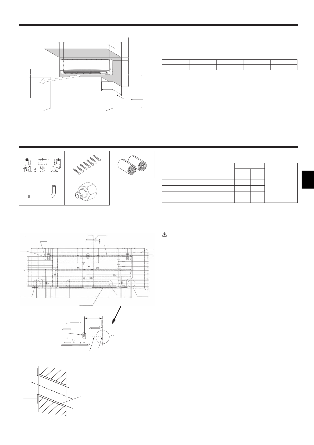
2.1. Outline dimensions (Indoor unit) (Fig. 2-1)
A
295
E
*
(mm)
C
K
365
D
J
H
I
Select a proper position allowing the following clearances for installation and
maintenance.
PKFY-P·VKM-E
ABCDE
Min. 100.5 Min. 22.4 Min. 48 Min. 250 Min. 220
F Air outlet: Do not place an obstacle within 1500 mm of the air outlet.
G Floor surface
H Furnishing
I When the projection dimension of a curtain rail or the like from the wall exceeds 60 mm,
extra distance should be taken because the fan air current may create a short cycle.
J 1800 mm or greater from the floor surface (for high location mounting)
K 108 mm or greater with left or rear left piping and optional drain pump installation
L 550 mm or greater with optional drain pump installation
M Minimum 7 mm: 265 mm or greater with optional drain pump installation
(mm)
3.1. Check the indoor unit accessories (Fig. 3-1)
The indoor unit should be supplied with the following accessories.
PART NUMBER
1
2
3
4
5
ACCESSORY
Mount board 1 1
Tapping screw 4 × 25
Felt tape 2 2
L-shaped connection pipe 1 1
Charge nut 1 1
QUANTITY
P63 P100
77
LOCATION OF SETTING
Fix at the back of the unit
PKFY-P·VKM-E
F
439
454
517.4
585
H
15.5
0
25
50
75
100
117
125
142
192
242
279.5
292
C
530.5
408.5
439
430.5
Fig. 3-1
3.2. Installing the wall mounting fixture
3.2.1. Setting the wall mounting fixture and piping positions
X Using the wall mounting fixture, determine the unit’s installation position
and the locations of the piping holes to be drilled.
54
G
0
3
100
A
216.5
314
R37.5
339
601001060
110
314
364
384
384
339
110
189
A
0
E
364
349.2
384.5
384
408.5
(mm)
Warning:
Before drilling a hole in the wall, you must consult the building contractor.
585
465.5
454
439
439
449.2
B
PKFY-P·VKM-E (Fig. 3-2)
54
25
0
12.5
37.5
62.5
87.5
104.5
129.5
167
217
229.5
264
292
308.5
311
D
A Mount board 1
B Indoor unit
C Bottom left rear pipe hole (ø75-ø80)
D Bottom right rear pipe hole (ø75-ø80)
E Knockout hole for left rear hole (75 × 480)
F Bolt hole (4-ø9 hole)
G Center measurement hole (ø2.5 hole)
H Tapping hole (75-ø5.1 hole)
I Hole centre
J Align the scale with the line.
K Insert scale.
3.2.2. Drilling the piping hole (Fig. 3-3)
X Use a core drill to make a hole of 75-80 mm diameter in the wall in the
piping direction, at the position shown in the diagram to the left.
X The hole should incline so that the outside opening is lower than the
K
inside opening.
X Insert a sleeve (with a 75 mm diameter and purchased locally) through the
hole.
I
J
Note:
The purpose of the hole’s inclination is to promote drain flow.
Fig. 3-2
A
B
A Sleeve
B Hole
C
E
C (Indoors)
D Wall
E (Outdoors)
Fig. 3-3
3
3. Installing the indoor unit
PKFY-P·VKM-E
F
A
D
C
E
I
H
Fig. 3-4
B
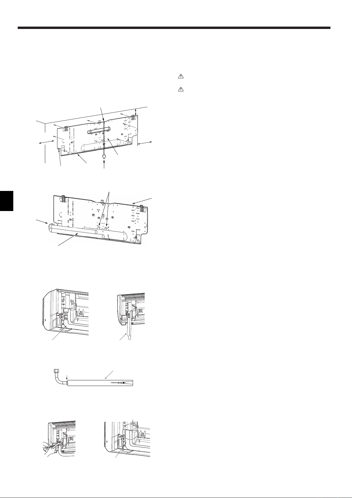
3.2.3. Installing the wall mounting fixture
X Since the indoor unit weighs near 21 kg, selection of the mounting
location requires thorough consideration. If the wall does not seem to be
strong enough, reinforce it with boards or beams before installation.
X The mounting fixture must be secured at both ends and at the centre, if
possible. Never fix it at a single spot or in any nonsymetrical way.
(If possible, secure the fixture at all the positions marked with a bold
arrow.)
Warning:
If possible, secure the fixture at all positions indicated with a bold arrow.
Caution:
• The unit body must be mounted horizontally.
• Fasten at the holes marked with S as shown by the arrows.
C
B
G
PKFY-P·VKM-E (Fig. 3-4)
A Min. 90 mm (617.6 mm or greater with optional drain pump installation)
B Min. 200 mm
C Min. 70 mm (130 mm or greater with left, rear left, or lower left piping, and optional drain
pump installation)
D Fixing screws (4 × 25) 2
E Level
F Fasten a thread to the hole.
Place the level against the horizontal reference line of the mount board and mount so that it is
G
level. Hang a weight from the thread and align with
H Weight
I Mount board 1
V
EPK of the mount board to permit leveling.
3.3. When embedding pipes into the wall (Fig. 3-5)
• The pipes are on the bottom left.
• When the cooling pipe, drain pipes internal/external connection lines etc are to
be embedded into the wall in advance, the extruding pipes etc, may have to be
A
bent and have their length modified to suit the unit.
• Use marking on the mount board as a reference when adjusting the length of the
embedded cooling pipe.
• During construction, give the length of the extruding pipes etc some leeway.
A Mount board 1
B Reference marking for flare connection
C Through hole
D On-site piping
PKFY-P·VKM-E
AA
C
D
3.4. Preparing the indoor unit
* Check beforehand because the preparatory work will differ depending on the
exiting direction of the piping.
Fig. 3-5
Fig. 3-7Fig. 3-6
B
A
Fig. 3-8
E
D
Fig. 3-10Fig. 3-9
* When bending the piping, bend gradually while maintaining the base of the
piping exiting portion. (Abrupt bending will cause misshaping of the piping.)
PKFY-P·VKM-E
Attachment of L-shaped connection pipe 4
Right, left and rear piping (Fig. 3-6)
1. Remove the flare nut and cap of the indoor unit. (Gas pipe only)
2. Apply refrigerating machine oil to the flare sheet surface. (Preparation on
location)
3. Facing the direction in which the L-shaped connection pipe 4 will be removed,
make a quick connection to the indoor unit flare connection opening.
4. Tighten the flare nut using a double open-end wrench. (Fig. 3-9)
Tightening force: 68 to 82 N·m
5. Attach the charge nut 5 to the liquid pipe side joint portion, and check for
leakage of the L-shaped connection pipe 4 connection portion.
Remove the charge nut 5 after completion of the work.
Tightening force: 34 to 42 N·m
6. Cover the flare connection portion with the pipe cover of the L-shaped
connection pipe 4 so that it is not exposed. (Fig. 3-10)
A L-shaped connection pipe 4
B Cut-off position (Straight pipe portion)
C Tightening direction
D Cover with pipe cover
E Cover the flare nut connection portion with the pipe cover.
Lower piping (Fig. 3-7)
1. Cut L-shaped connection pipe 4 at the position indicated in (Fig. 3-8).
2. Insert the flare nut that was removed earlier onto the straight pipe side of the cut
L-shaped connection pipe 4 and then flare the end of the pipe.
3. Remove the flare nut and cap of the indoor unit. (Gas pipe only)
4. Apply refrigerating machine oil to the flare sheet surface. (Preparation on
location)
5. Quickly connect the L-shaped connection pipe 4 that has been processed as
described in part 2) to the indoor unit flare connection opening.
6. Tighten the flare nut using a double open-end wrench. (Fig. 3-9)
Tightening force: 68 to 82 N·m
7. Attach the charge nut 5 to the liquid pipe side joint portion, and check for
leakage of the L-shaped connection pipe 4 connection portion.
Remove the charge nut 5 after completion of the work.
Tightening force: 34 to 42 N·m
8. Cover the flare connection portion with the pipe cover of the L-shaped
connection pipe 4 so that it is not exposed. (Fig. 3-10)
4
3. Installing the indoor unit
E
A
Leakage check of the L-shaped connection pipe connection portion
1. Attach the charge nut 5 to the liquid pipe side joint portion.
Tightening force: 34 to 42 N·m
2. Pressurize by filling with nitrogen gas from the charge nut.
Do not pressurize to the current constant pressure all at once. Pressurize
gradually.
1) Pressurize to 0.5 MPa, wait five minutes, and make sure the pressure does
not decrease.
2) Pressurize to 1.5 MPa, wait five minutes, and make sure the pressure does
not decrease.
3) Pressurize to 4.15 MPa and measure the surrounding temperature and
refrigerant pressure.
3. If the specified pressure holds for about one day and does not decrease, the
pipes have passed the test and there are no leaks.
• If the surrounding temperature changes by 1°C, the pressure will change by
about 0.01 MPa. Make the necessary corrections.
4. If the pressure decreases in steps (2) or (3), there is a gas leak. Look for the
source of the gas leak.
C
D
A
B
Fig. 3-11
)
1
)
2
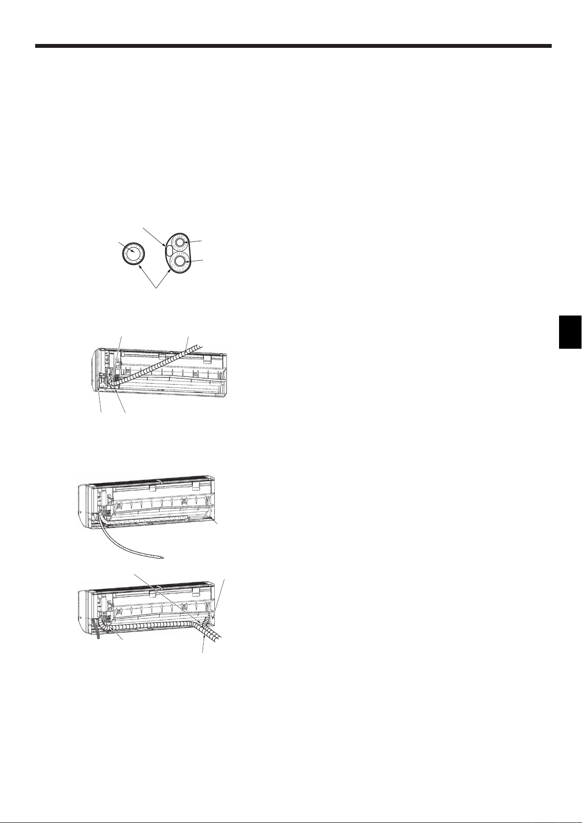
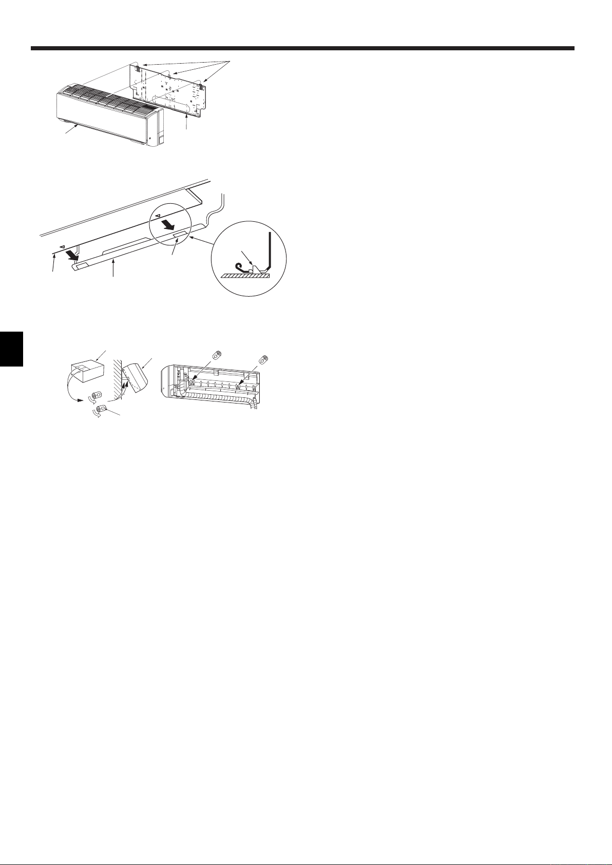
Extraction and processing of the piping and wiring (Fig. 3-11)
1. Connection of indoor/outdoor wiring See page. 8.
2. Wrap the felt tape 3 in the range of the refrigerant piping and drain hose which
will be housed within the piping space of the indoor unit.
• Wrap the felt tape 3 securely from the base for each of the refrigerant piping
and the drain hose.
• Overlap the felt tape 3 at one-half of the tape width.
• Fasten the end portion of the wrapping with vinyl tape.
A Liquid pipe
B Gas pipe
C Indoor/outdoor connection cable
D Drain hose
E Felt tape 3
3. Be careful that the drain hose is not raised, and that contact is not made with the
indoor unit box body.
Do not pull the drain hose forcefully because it might come out.
Rear, right and lower piping (Fig. 3-12)
1) Be careful that the drain hose is not raised, and that contact is not made with
the indoor unit box body.
Arrange the drain hose at the underside of the piping and wrap it with felt
B
Fig. 3-12
tape 3.
2) Securely wrap the felt tape 3 starting from the base. (Overlap the felt tape at
one-half of the tape width.)
A Cut off for right piping.
B Cut off for lower piping.
Left and left rear piping (Fig. 3-13)
4. Drain hose replacement See 6. Drainage piping work
Be sure to replace the drain hose and the drain cap for the left and rear left
piping. Dripping may occur if you forget to install or fail to replace these parts.
C Drain cap
1) Be careful that the drain hose is not raised, and that contact is not made with
the indoor unit box body.
C
2) Securely wrap the felt tape 3 starting from the base. (Overlap the felt tape at
one-half of the tape width.)
3) Fasten the end portion of the felt tape 3 with vinyl tape.
D Cut off for left piping.
)
1
)
2
D
)
3
Fig. 3-13
5
3. Installing the indoor unit
D
B
B
PKFY-P·VKM-E
C
C
3.5. Mounting the indoor unit
1. Affix the mount board 1 to the wall.
2. Hang the indoor unit on the hook positioned on the upper part of the mount
board.
Rear, right and lower piping (Fig. 3-14)
3. While inserting the refrigerant piping and drain hose into the wall penetration
A
Fig. 3-14
C
D
A
Fig. 3-15
B
A
hole (penetration sleeve), hang the top of the indoor unit to the mount board 1.
4. Move the indoor unit to the left and right, and verify that the indoor unit is hung
securely.
5. Fasten by pushing the bottom part of the indoor unit onto the mount board 1.
(Fig. 3-15)
* Check that the knobs on the bottom of the indoor unit are securely hooked into
the mount board 1.
6. After installation, be sure to check that the indoor unit is installed level.
A Mount board 1
B Indoor unit
C Hook
D square hole
Left and left rear piping (Fig. 3-16)
3. While inserting the drain hose into the wall penetration hole (penetration sleeve),
hang the top of the indoor unit to the mount board 1.
Giving consideration to the piping storage, move the unit all the way to the left
side, then cut part of the packaging carton and wrap into a cylindrical form as
illustrated in the diagram. Hook this to the rear surface rib as a spacer, and raise
the indoor unit.
4. Connect the refrigerant piping with the site-side refrigerant piping.
5. Fasten by pushing the bottom part of the indoor unit onto the mount board 1.
* Check that the knobs on the bottom of the indoor unit are securely hooked into
the mount board 1.
6. After installation, be sure to check that the indoor unit is installed level.
A Indoor unit
B Packaging carton
C Cut off
D Wrap into a cylindrical form
E Fasten with tape
E
Fig. 3-16
6

4. Installing the refrigerant piping
A
90°±0.5°
A Flare cutting dimensions
45±2°
øA
Copper pipe O.D.
R0.4~R0.8
(mm)
ø9.52 12.8 - 13.2
ø15.88 19.3 - 19.7
ø19.05 22.9 - 23.3
B
Fig. 4-1
Flare dimensions
øA dimensions (mm)
C
4.1. Connecting pipes (Fig. 4-1)
• When commercially available copper pipes are used, wrap liquid and gas pipes
with commercially available insulation materials (heat-resistant to 100 °C or
more, thickness of 12 mm or more).
• The indoor parts of the drain pipe should be wrapped with polyethylene foam
D
insulation materials (specific gravity of 0.03, thickness of 9 mm or more).
• Apply thin layer of refrigerant oil to pipe and joint seating surface before
tightening flare nut.
• Use two wrenches to tighten piping connections.
• Use refrigerant piping insulation provided to insulate indoor unit connections.
Insulate carefully.
B Refrigerant pipe sizes & Flare nut tightening torque
C Do not apply refrigerating machine oil to the screw portions.
(This will make the flare nuts more apt to loosen.)
D Be certain to use the flare nuts that are attached to the main unit.
(Use of commercially-available products may result in cracking.)
R407C or R22 R410A
Liquid pipe Gas pipe Liquid pipe Gas pipe
Pipe size O.D.
(mm)
P63 ODø9.52 (3/8”) 34 - 42 ODø15.88 (5/8”) 68 - 82 ODø9.52 (3/8”) 34 - 42 ODø15.88 (5/8”) 68 - 82 22 29
P100 ODø9.52 (3/8”) 34 - 42 ODø19.05 (3-4”) 68 - 82* ODø9.52 (3/8”) 34 - 42 ODø15.88 (5/8”) 68 - 82 22 29
* Connect the joint with the following pipes: Liquid and gas pipes of P50, gas pipe of P100/P125.
E Apply refrigerating machine oil over the entire flare seat surface.
Tightening
torque.
(N·m)
Pipe size O.D.
(mm)
Tightening
torque.
(N·m)
Pipe size O.D.
(mm)
Tightening
torque.
(N·m)
Pipe size O.D.
(mm)
Tightening
torque.
(N·m)
Flare nut O.D.
Liquid
pipe
(mm)
Gas
pipe
(mm)
PKFY-P·VKM-E
67
777.8
65
365
D
65
77
87
1170
444 (A)* 123
482 (B)
585 (C)
1155
FF
Fig. 4-2
4.2. Positioning refrigerant and drain piping (Fig. 4-2)
PKFY-P·VKM-E
A Gas pipe * Indicates the condition with accessories mounted.
B Liquid pipe
C Drain hose
D Left-side piping knockout hole
E Right-side piping knockout hole
F Lower piping knockout hole
G Mount board 1
77
87 71.218.2
154
134
65
295 5
65
67
77
7.8
G
E
7
 Loading...