

Mitsubishi PKA-P1.6GAL, PKA-P2GAL, PKH-P1.6GALH, PKH-P2GALH, PKA-P1.6GAL1 Service Manual
...Page 1
ON/OFF
SPLIT-TYPE, HEAT PUMP AIR CONDITIONERS
TECHNICAL & SERVICE MANUAL
1999
No.OC176
REVISED EDITION-B
Series PKH/PKA
Indoor unit
[Model names]
1999, 2001
PKH-P1.6GALH
PKH-P2GALH
2000, 2001
PKA-P1.6GAL
PKA-P2GAL
Indoor unit
PKH-P1.6, 2GALH
PKA-P1.6, 2GAL
Remote controller
PKH-P1.6GALH1, PKH-P2GALH1, PKA-P1.6GAL1 and PKA-P2GAL1
are added in Revised Edition-B.
Please void OC176 Revised Edition-A.
Refer to the OCT03 Revised Edition-C as regarding control relation.
This manual does not cover outdoor units. When servicing them,
please refer to the service manual No.OC180 Revised Edition-A,
OC261 and this manual in a set.
Wall Mounted
[Service Ref.]
1999
PKH-P1.6GALH
PKH-P2GALH
2000
PKA-P1.6GAL
PKA-P2GAL
PKH-P1.6, 2GALH1
PKA-P1.6, 2GAL1
R407C
2001
PKH-P1.6GALH1
PKH-P2GALH1
2001
PKA-P1.6GAL
1
PKA-P2GAL1
CONTENTS
1. TECHNICAL CHANGES······································2
2. COMBINATION OF INDOOR AND OUTDOOR UNITS···2
3. SAFETY PRECAUTION·······································3
4. PART NAMES AND FUNCTIONS ·······················4
5. SPECIFICATIONS················································7
6. DATA ··································································13
7. OUTLINES AND DIMENSIONS·························32
8. WIRING DIAGRAM ············································33
9.
REFRIGERANT SYSTEM DIAGRAM
10. TROUBLE SHOOTING ······································36
11. DISASSEMBLY PROCEDURE···························37
12. PARTS LIST ·······················································41
13. OPTIONAL PARTS ························BACK COVER
······················35
Page 2

1 TECHNICAL CHANGES
ON/OFF
PKH-P1.6GALH ➔ PKH-P1.6GALH1 PKA-P1.6GAL ➔ PKA-P1.6GAL1
PKH-P2GALH ➔ PKH-P2GALH1 PKA-P2GAL ➔ PKA-P2GAL1
● Outdoor units which are connected to PKH-P·GALH, PKH-P·GALH1.PKA-P·GAL and PKA-P·GAL1 have been added.
● The parts No. of REMOTE CONTROLLER has changed.
(The following parts numbers are interchangeable.)
➔
[ T7W E02 714 ] [ T7W E06 714 ]
2 COMBINATION OF INDOOR AND OUTDOOR UNITS
Outdoor unit (OC180 REVISED EDITION-A)
Heat pump with
electric heater
Heat pump without
electric heater
or
Cooling only
Indoor unit
PKH-P1.6GALH
PKH-P2GALH
PKA-P1.6GAL
PKA-P2GAL
Indoor unit
Heat pump type
PUH-P
1.6VGA 1.6YGA 2VGA 2YGA 1.6VGA 2VGA
—
—
—
—
—
—
Outdoor unit (OC261)
Heat pump type
PUH-P
1.6VGAA.UK 1.6YGAA.UK
2VGAA.UK 2YGAA.UK
Cooling only type
PU-P
—
—
—
—
—
Cooling only type
1.6VGAA.UK 1.6YGAA.UK
—
—
—
PU-P
2VGAA.UK 2YGAA.UK
Heat pump with
electric heater
Heat pump without
electric heater
or
Cooling only
PKH-P1.6GALH1
PKH-P2GALH
PKA-P1.6GAL
PKA-P2GAL
1
—
—
1
1
—
—
—
—
—
—
—
—
—
—
—
—
—
—
—
—
—
—
2
Page 3

3
SAFETY PRECAUTION
Cautions for using with the outdoor unit which adopts R407C refrigerant.
· Do not use the existing refrigerant piping.
-The old refrigerant and refrigerant oil in the existing piping contains a large amount of chlorine which may cause the refrigerant oil of the new unit to deteriorate.
· Do not use copper pipes which are broken, deformed or discolour .
In addition, be sure that the inner surfaces of the pipes are clean, free of hazardous sulphur and oxides, or have no dust /
dirt, shaving particles, oils, moisture or any other contamination.
-If there is a large amount of residual oil (hydraulic oil, etc.) inside the piping and joints, deterioration of the refrigerant oil will
result.
· Store the piping to be used during installation indoors and keep both ends of the piping sealed until just before
brazing. (Store elbows and other joints in a plastic bag.)
-If dust, dirt, or water enters the refrigerant cycle, deterioration of the oil and compressor trouble may result.
· Use ester oil, ether oil or alkyl benzene (small amount) as the refrigerant oil to coat flares and flange connections.
-The refrigerant oil will degrade if it is mixed with a large amount of mineral oil.
Use liquid refrigerant to fill the system.
-If gas refrigerant is used to fill the system, the composition of the refrigerant in the cylinder will change and performance
may drop.
· Do not use a refrigerant other than R407C.
-If another refrigerant (R22, etc.) is used, the chlorine in the refrigerant may cause the refrigerant oil to deteriorate.
· Use a vacuum pump with a reverse flow check valve.
-The vacuum pump oil may flow back into the refrigerant cycle and cause the refrigerant oil to deteriorate.
· Do not use the following tools that are used with conventional refrigerant.
(Gauge manifold , charge hose, gas leak detector, reverse flow check valve, refrigerant charge base, vacuum gauge,
refrigerant recovery equipment)
-If the conventional refrigerant and refrigerant oil are mixed in the R407C, the refrigerant may deteriorated.
-If water is mixed in the R407C, the refrigerant oil may deteriorate.
-Since R407C does not contain any chlorine, gas leak detectors for conventional refrigerant will not react to it.
· Do not use a charging cylinder.
-Using a charging cylinder may cause the refrigerant to deteriorate.
· Be especially careful when managing the tools.
-if dust, dirt, or water gets in the refrigerant cycle, the refrigerant may deteriorate.
· Don’t use the drier which is sold in the field.
-The drier for R407C refrigerant is Per-attached to outdoor unit refrigerant circuit.
-Some drier in the field are not in conformity with R407C refrigerant.
[1] Service tools
Use the below service tools as exclusive tools for R407C refrigerant.
No. Tool name Specifications
Gauge manifold ·Only for R407C.
1
·Use the existing fitting SPECIFICATIONS. (UNF7/16)
·Use high-tension side pressure of 3.43MPa·G or over.
Charge hose ·Only for R407C.
2
·Use pressure performance of 5.10MPa·G or over.
Electronic scale
3
Gas leak detector ·Use the detector for R407C.
4
Adapter for reverse flow check ·Attach on vacuum pump.
5
Refrigerant charge base
6
Refrigerant cylinder ·For R407C ·Top of cylinder (Brown)
7
·Cylinder with syphon
Refrigerant recovery equipment
8
3
Page 4

Gravimeter
Unit
[2] Notice on repair service
·After recovering the all refrigerant in the unit, proceed to working.
·Do not release refrigerant in the air.
·After completing the repair service, recharge the cycle with the specified amount of
liquid refrigerant.
[3] Refrigerant recharging
(1) Refrigerant recharging process
1Direct charging from the cylinder.
·R407C cylinder are available on the market has a syphon pipe.
·Leave the syphon pipe cylinder standing and recharge it.
(By liquid refrigerant)
(2) Recharge in refrigerant leakage case
·After recovering the all refrigerant in the unit, proceed to working.
·Do not release the refrigerant in the air.
·After completing the repair service, recharge the cycle with the specified amount of
liquid refrigerant.
4 PART NAMES AND FUNCTIONS
● Indoor Unit
Filter
Air intake
Air intake grille
Guide vane
Auto vane
Air outlet
4
Page 5
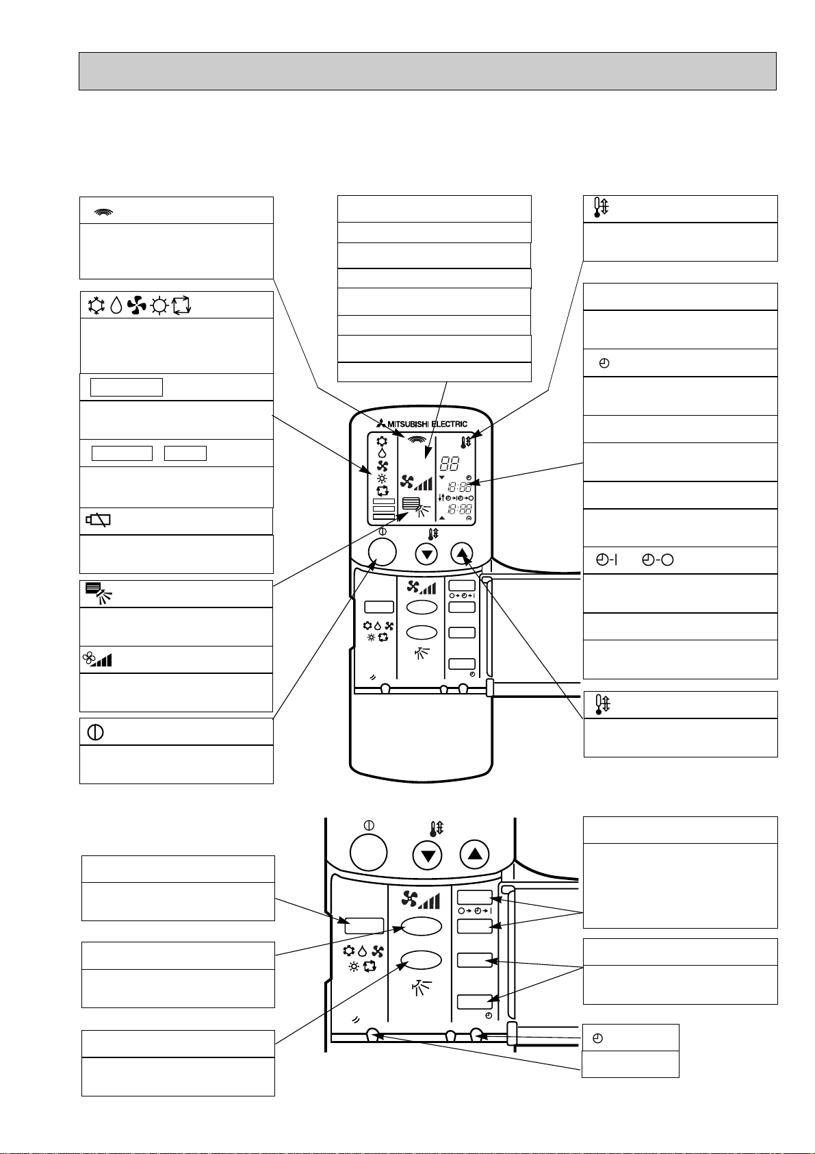
●Wireless remote controller
PKH-P1.6GALH, PKH-P2GALH
PKA-P1.6GAL, PKA-P2GAL
● When cover is open.
display
Lights up while transmission to the indoor unit
is mode using switches.
display
OPERATION MODE display
Operation mode display indicates which operation mode is in effect.
• FUNCTION
Lights up when function are set..
display
• TEST RUN • CHECK display
CHECK&TEST RUN display indicates that the
unit is being checked or test-run.
display
Displays when batteries are dead.
display
The vertical direction of airflow is indicated.
display
FAN SPEED display indicates which fan
speed has been selected.
ADDRESS display
Displays the refrigerant address.
UNIT NO. display
Displays the number of unit..
FUNCTION NO. display
Displays the mode.
SELECTION NO. display
Displays the selection number..
ADDRESS
UNIT No.
FUNCTION No.
SELECTION No.
FUNCTION
TEST RUN
CHECK
ON/OFF
MODE FAN
RESET
VANE
AM
PM
AM
PM
TEMP.
˚C
START
STOP
HR.
MIN.
display
SET TEMP. display indicates desired temperature set.
CLOCK display
DIsplays the current time.
“ ”display
Flashes when the current time is displayed.
TIMER display
Displays when in timer operation or when setting timer.
➡
“ ” “ ” display
➡
Displays the order of timer operation.
“ ” “ ” display
Displays whether timer is on or off.
▼
“ ” “ ” display
Displays when the current time and the timer
time can be changed.
▼
TEMP. button
display
The unit is turned ON and OFF alternately
each time the button is pressed.
● When cover is open.
MODE SELECT button
Used to switch the operation mode between
cooling , drying , blowing , heating and auto
mode.
FAN SPEED SELECT button
Used to change the fan speed.
VANE CONTROL button
Used to change the airflow direction.
ON/OFF
MODE FAN
RESET
5
VANE
TEMP.
START
STOP
HR.
MIN.
SET TEMPERATURE button sets any desired
room temperature.
TIMER CONTROL buttons
STOP (OFF timer): when this switch is set,
the air conditioner will be automatically
stopped at the preset time.
START(ON timer): when this switch is set, the
air conditioner will be automatically started at
the preset time.
HR. and MIN.buttons
Buttons used to set the “hour and minute” of
the current time and timer settings.
button
RESET button
Page 6
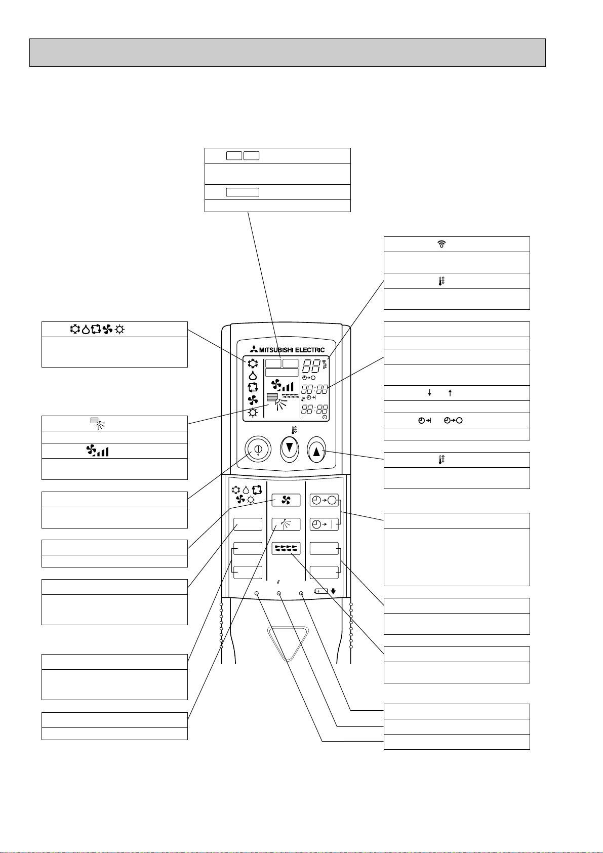
●Wireless remote controller
ON/OFF TEMP
FAN
VANE
TEST RUN
AUTO STOP
AUTO START
h
min
LOUVER
MODE
CHECK
RESETSET CLOCK
MODEL SELECT
NOT AVAILABLE
CHECK
TEST RUN
˚C
AMPM
AMPM
VANE CONTROL button
Used to change the air flow direction.
CLOCK button
RESET button
SET button
ON/OFF button
The unit is turned ON and OFF alternately
each time the button is pressed.
LOUVER button
This switch the horizontal fan motion ON
and OFF.
(Not available for this model.)
MODE SELECT button
Used to switch the operation mode between
cooling, drying, blowing, heating and auto
mode.
CHECK-TEST RUN button
Only press this button to perform an inspection check or test operation.
Do not use it for normal operation.
FAN SPEED SELECT button
Used to change the fan speed.
TIMER display
Displays when in timer operation or when
setting timer.
button
SET TEMPERATURE button sets any desired
room temperature.
CLOCK display
Displays the current time.
“ ” “ ” display
Displays the order of timer operation.
“ ” “ ” display
Displays whether timer is on or off.
w In case the outdoor unit is cool only type,
the heating and auto mode not available.
Buttons used to set the “hour and minute” of
the current time and timer settings.
h and min buttons
display
SET TEMP. display indicates desired temperature set.
display
FAN SPEED display indicates which fan
speed has been selected.
display
The vertical direction of air flow is indicated.
display
Blinks when model is selected.
display
Lights up while transmission to the indoor
unit is mode using switches.
display
CHECK&TEST RUN display indicates that
the unit is being checked or test-run.
display
OPERATION MODE display
Operation mode display indicates which operation mode is in effect.
TIMER CONTROL buttons
AUTO STOP (OFF timer): when this switch
is set, the air conditioner will be automatically stopped at the preset time.
AUTO START (ON timer): when this switch
is set, the air conditioner will be automatically started at the preset time.
MODEL SELECT
CHECK
TEST RUN
PKH-P1.6GALH
1, PKH-P2GALH1
PKA-P1.6GAL1, PKA-P2GAL1
● When cover is open.
6
Page 7
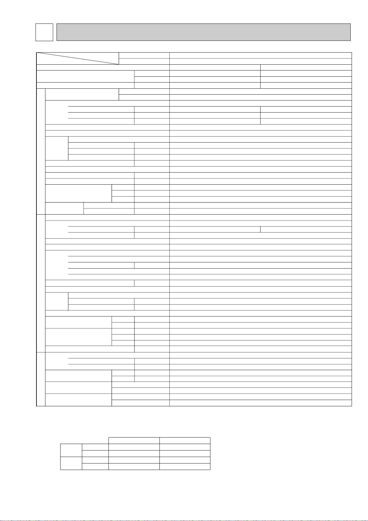
5
Cooling
15,000
4,400
1.78
0.07
0.33
0.40
7.66 / 2.67
Heating
17,100(19,800)
5,000(5,800)
1.90(2.70)
0.07<0.80>
0.33<3.33>
0.40<3.33>
8.19 / 2.86
Single phase, 50Hz, 220-230-240V
Munsell 0.70Y8.59/0.97
Plate fin coil
Line flow (direct) x 1
0.030
9-10-11-12(318-353-388-424)
0(direct blow)
<0.80>
Wireless remote controller & built-in
36-38-41-43
20(13/16)
990(39)
235(9-1/4)
340(13-3/8)
17(37)
16(35)
PUH-P1.6VGA / PUH-P1.6YGA
Single phase, 50Hz, 220-230-240V / 3 phases, 50Hz, 380-400-415V(4wires)
36 / 20
Munsell 5Y 8/1
Linear Expansion Valve
Hermetic
RE277VHSM / RE277YFKM
1.3
Line start
Internal thermostat, HP switch, Discharge thermo. / Thermal relay, Discharge thermo, HP switch, Anti-phase protector.
30
Plate fin coil
Propeller (direct) x 1
0.070
45(1,590)
Reverse cycle
46
48
900(35-7/16)
330+20(13+3/4)
650(25-5/8)
55(121)
R407C
2.6(5.7)
0.57 (Ester)MEL56
9.52 (3/8)
15.88 (5/8)
Flared
Flared
Max. 40m
Max. 40m
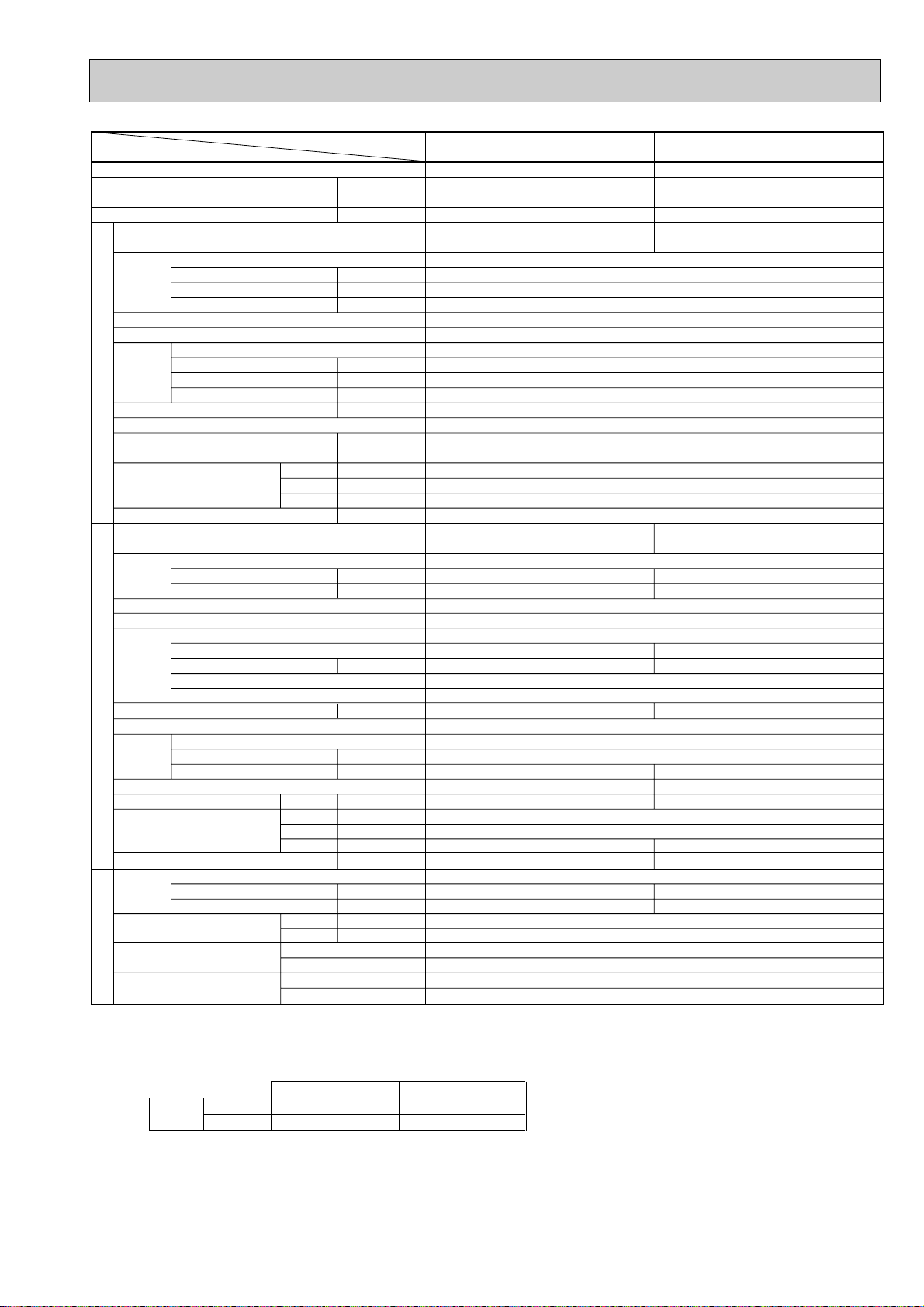
PKH-P1.6GALH
PKA-P1.6GAL
Service Ref.
With Electric heater
Without Electric heater
With Electric heater
Without Electric heater
With Electric heater
Without Electric heater
Item
Btu/h
W
kW
kW
A
A
kW
K/min(CFM)
Pa(mmAq)
kW
dB
mm(in.)
mm(in.)
mm(in.)
mm(in.)
kg(lbs)
kg(lbs)
A
A
kW
W
kW
K
/min(CFM
)
dB
dB
mm(in.)
mm(in.)
mm(in.)
kg(lbs)
kg(lbs)
L
mm(in.)
mm(in.)
Function
Capacity w1
Total input w1
Service Ref.
Power supply(phase, cycle,voltage)
Input w2
Running current w2
Starting current w2
External finish
Heat exchanger
Fan Fan(drive) x No.
Fan motor output
Airflow(Lo-Mi2-Mi1-Hi)
External static pressure
Booster heater w2
Operation control & Thermostat
Noise level(Lo-Mi2-Mi1-Hi)
Unit drain pipe O.D.
Dimensions
Weight
Service Ref.
Power supply (phase, cycle, voltage)
Running current
Starting current
External finish
Refrigerant control
Compressor
Model
Motor output
Starter type
Protection devices
Crankcase heater
Heat exchanger
Fan Fan(drive) x No.
Fan motor output
Airflow
Defrost method
Noise level
Dimensions
Weight
Refrigerant
Charge
Oil (Model)
Pipe size O.D.
Connection method
Between the indoor &
outdoor unit
INDOOR UNITOUTDOOR UNIT
REFRIGERANT PIPING
W
D
H
Cooling
Heating
W
D
H
Liquid
Gas
Indoor side
Outdoor side
Height difference
Piping length
Notes1.Rating Conditions (ISO T1)
Cooling :Indoor : D.B. 27˚C(80˚F), W.B. 19˚C (66˚F) Outdoor : D.B. 35˚C(95˚F), W.B. 24˚C (75˚F)
Heating :Indoor : D.B. 20˚C(68˚F) Outdoor : D.B. 7˚C(45˚F), W.B. 6˚C (43˚F)
Refrigerant piping length (one way) : 5m (16ft)
3. Above data based on indicated voltage
Indoor Unit Single phase 240V 50Hz
Outdoor Unit Single phase 240V 50Hz / 3 phase 415V 50Hz
2. Guaranteed operating range
Upper limit
Lower limit
Upper limit
Lower limit
Indoor
D.B. 35˚C, W.B. 22.5˚C
D.B. 19˚C, W.B. 15˚C
D.B. 28˚C
D.B. 17˚C
Outdoor
D.B. 46˚C
D.B. -5˚C
D.B. 24˚C, W.B. 18˚C
D.B. -11˚C, W.B. -12˚C
Cooling
Heating
w1 : ( ) Shows the total rating.
w2 : < > Shows the only booster heater rating.
PKH-P1.6GALH
PKA-P1.6GAL
SPECIFICATIONS
1. Heat pump
7
Page 8

Item
Function
Capacity w1
Total input w1
Service Ref.
Power supply(phase, cycle,voltage)
External finish
Heat exchanger
Fan Fan(drive) x No.
INDOOR UNITOUTDOOR UNIT
Booster heater w2
Operation control & Thermostat
Noise level(Lo-Mi2-Mi1-Hi)
Unit drain pipe O.D.
Dimensions
Weight
Service Ref.
Power supply (phase, cycle, voltage)
External finish
Refrigerant control
Compressor
Crankcase heater
Heat exchanger
Fan Fan(drive) x No.
Defrost method
Noise level
Dimensions
Weight
Refrigerant
Pipe size O.D.
Connection method
Between the indoor &
REFRIGERANT PIPING
outdoor unit
Notes1.Rating Conditions (ISO T1)
2. Guaranteed operating range
3. Above data based on indicated voltage
Input w2
Running current w2
Starting current w2
Fan motor output
Airflow(Lo-Mi2-Mi1-Hi)
External static pressure
Running current
Starting current
Model
Motor output
Starter type
Protection devices
Fan motor output
Airflow
Charge
Oil (Model)
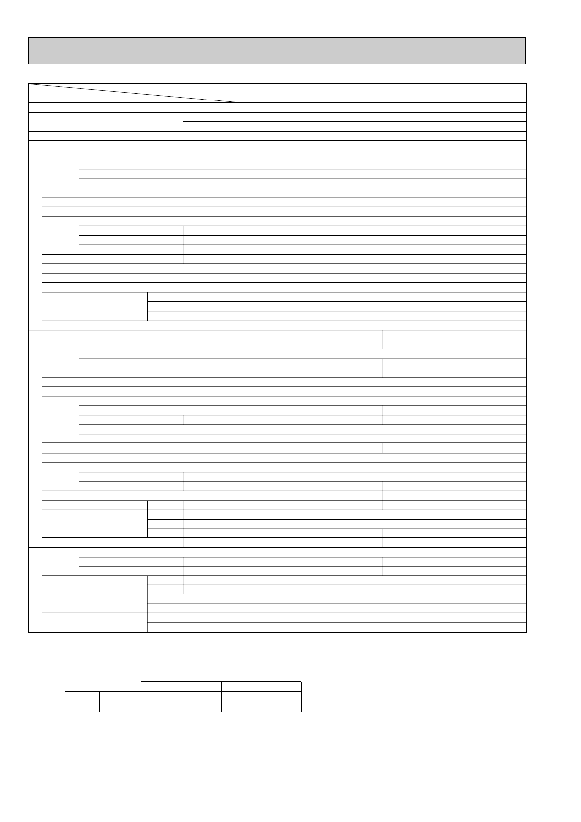
Cooling :Indoor : D.B. 27˚C(80˚F), W.B. 19˚C (66˚F) Outdoor : D.B. 35˚C(95˚F), W.B. 24˚C (75˚F)
Heating :Indoor : D.B. 20˚C(68˚F) Outdoor : D.B. 7˚C(45˚F), W.B. 6˚C (43˚F)
Refrigerant piping length (one way) : 5m (16ft)
Cooling
Heating
Indoor Unit Single phase 240V 50Hz
Outdoor Unit Single phase 240V 50Hz / 3 phase 415V 50Hz
Service Ref.
With Electric heater
Without Electric heater
Upper limit
Lower limit
Upper limit
Lower limit
With Electric heater
Without Electric heater
Btu/h
W
With Electric heater
Without Electric heater
W
D
H
Cooling
Heating
W
D
H
Liquid
Gas
Indoor side
Outdoor side
Height difference
Piping length
Indoor
D.B. 35˚C, W.B. 22.5˚C
D.B. 19˚C, W.B. 15˚C
D.B. 28˚C
D.B. 17˚C
kW
kW
A
A
kW
K/min(CFM)
Pa(mmAq)
kW
dB
mm(in.)
mm(in.)
mm(in.)
mm(in.)
kg(lbs)
kg(lbs)
A
A
kW
W
kW
/min(CFM
K
dB
dB
mm(in.)
mm(in.)
mm(in.)
kg(lbs)
kg(lbs)
L
mm(in.)
mm(in.)
Cooling
18,800
5,500
2.55
Single phase, 50Hz, 220-230-240V
0.07
0.33
0.40
Wireless remote controller & built-in
Single phase, 50Hz, 220-230-240V / 3 phases, 50Hz, 380-400-415V(4wires)
11.11 / 3.88
Internal thermostat, HP switch, Discharge thermo. / Thermal relay, Discharge thermo, HP switch, Anti-phase protector.
)
Outdoor
D.B. 46˚C
D.B. -5˚C
D.B. 24˚C, W.B. 18˚C
D.B. -11˚C, W.B. -12˚C
PKH-P2GALH
PKA-P2GAL
PKH-P2GALH
PKA-P2GAL
Munsell 0.70Y 8.59/0.97
Line flow (direct) x 1
9-10-11-12(318-353-388-424)
0(direct blow)
PUH-P2VGA / PUH-P2YGA
Munsell 5Y 8/1
Linear Expansion Valve
NE38VMJM / NE38YEJM
Propeller (direct) x 1
Reverse cycle
900(35-7/16)
330+20(13+3/4)
1.2 (Ester)MEL56
w1 : ( ) Shows the total rating.
w2 : < > Shows the only booster heater rating.
Heating
22,300(25,100)
6,550(7,350)
2.64(3.44)
0.07<0.80>
0.33<3.33>
0.40<3.33>
Plate fin coil
0.030
<0.80>
36-38-41-43
20(13/16)
990(39)
235(9-1/4)
340(13-3/8)
17(37)
16(35)
11.51 / 4.02
74 / 30
Hermetic
1.7
Line start
38
Plate fin coil
0.070
55(1,940)
48
49
855(33-5/8)
71(157)
R407C
3.1(6.8)
9.52 (3/8)
15.88 (5/8)
Flared
Flared
Max. 40m
Max. 40m
8
Page 9
2. Cooling only type
Item
Function
Capacity
Total input
Service Ref.
Power supply(phase, cycle,voltage)
External finish
Heat exchanger
Fan Fan(drive) x No.
INDOOR UNITOUTDOOR UNIT
Booster heater
Operation control & Thermostat
Noise level(Lo-Mi2-Mi1-Hi)
Unit drain pipe O.D.
Dimensions
Weight
Service Ref.
Power supply (phase, cycle, voltage)
External finish
Refrigerant control
Compressor
Crankcase heater
Heat exchanger
Fan Fan(drive) x No.
Defrost method
Noise level
Weight
Refrigerant
Pipe size O.D.
Connection method
Between the indoor &
REFRIGERANT PIPING
outdoor unit
Notes1. Rating Conditions (ISO T1)
Input
Running current
Starting current
Fan motor output
Airflow(Lo-Mi2-Mi1-Hi)
External static pressure
Running current
Starting current
Model
Motor output
Starter type
Protection devices
Fan motor output
Airflow
Dimensions
Charge
Oil (Model)
Cooling :Indoor : D.B. 27˚C(80˚F), W.B. 19˚C (66˚F) Outdoor : D.B. 35˚C(95˚F), W.B. 24˚C (75˚F)
Refrigerant piping length (one way) : 5m (16ft)
Service Ref.
K/min(CFM)
Pa(mmAq)
mm(in.)
W
D
H
Cooling
W
D
H
Liquid
Gas
Indoor side
Outdoor side
Height difference
Piping length
mm(in.)
mm(in.)
mm(in.)
kg(lbs)
/min(CFM
K
mm(in.)
mm(in.)
mm(in.)
kg(lbs)
kg(lbs)
mm(in.)
mm(in.)
Btu/h
W
kW
kW
A
A
kW
kW
dB
A
A
kW
W
kW
dB
L
PKA-P1.6GAL PKA-P2GAL
Cooling
15,000
4,400
1.78
PKA-P1.6GAL
Single phase, 50Hz, 220-230-240V
Munsell 0.70Y 8.59/0.97
9-10-11-12 (318-353-388-424)
Wireless remote controller & built-in
PU-P1.6VGA
Single phase, 50Hz, 220-230-240V
7.66
36
Linear Expansion Valve
RE277VHSM
1.3
Internal thermostat, HP switch, Discharge thermo.
30
)
45(1,590)
—
46
650(25-5/8)
55(121)
2.6(5.7)
0.57 (Ester)MEL56
0.07
0.33
0.40
Plate fin coil
Line flow (direct) x 1
0.030
0(direct blow)
—
36-38-41-43
20(13/16)
990(39)
235(9-1/4)
340(13-3/8)
16(35)
Munsell 5Y 8/1
Hermetic
Line start
Plate fin coil
Propeller (direct) x 1
0.070
900(35-7/16)
330+20(13+3/4)
R407C
9.52 (3/8)
15.88 (5/8)
Flared
Flared
Max. 40m
Max. 40m
Cooling
18,800
5,500
2.55
PKA-P2GAL
PU-P2VGA
11.11
74
NE38VMJM
1.7
38
55(1,940)
—
48
855(33-5/8)
71(157)
3.1(6.8)
1.2 (Ester)MEL56
2. Guaranteed operating range
Indoor
Cooling
3. Above data based on indicated voltage
Upper limit
Lower limit
Indoor Unit Single phase 240V 50Hz
Outdoor Unit Single phase 240V 50Hz
D.B. 35˚C, W.B. 22.5˚C
D.B. 19˚C, W.B. 15˚C
Outdoor
D.B. 46˚C
D.B. -5˚C
9
Page 10

3. Heat pump
Item
Function
Capacity w1
Total input w1
Service Ref.
Power supply(phase, cycle,voltage)
External finish
Heat exchanger
Fan Fan(drive) x No.
INDOOR UNITOUTDOOR UNIT
Booster heater w2
Operation control & Thermostat
Noise level(Lo-Mi2-Mi1-Hi)
Unit drain pipe O.D.
Dimensions
Weight
Service Ref.
Power supply (phase, cycle, voltage)
External finish
Refrigerant control
Compressor
Crankcase heater
Heat exchanger
Fan Fan(drive) x No.
Defrost method
Noise level
Dimensions
Weight
Refrigerant
Pipe size O.D.
Connection method
Between the indoor &
REFRIGERANT PIPING
outdoor unit
Notes1.Rating Conditions (ISO T1)
2. Guaranteed operating range
3. Above data based on indicated voltage
Input w2
Running current w2
Starting current w2
Fan motor output
Airflow(Lo-Mi2-Mi1-Hi)
External static pressure
Running current
Starting current
Model
Motor output
Starter type
Protection devices
Fan motor output
Airflow
Charge
Oil (Model)
Cooling :Indoor : D.B. 27˚C(80˚F), W.B. 19˚C (66˚F) Outdoor : D.B. 35˚C(95˚F), W.B. 24˚C (75˚F)
Heating :Indoor : D.B. 20˚C(68˚F) Outdoor : D.B. 7˚C(45˚F), W.B. 6˚C (43˚F)
Refrigerant piping length (one way) : 5m (16ft)
Cooling
Heating
Indoor Unit Single phase 240V 50Hz
Outdoor Unit Single phase 240V 50Hz / 3 phase 415V 50Hz
Service Ref.
With Electric heater
Without Electric heater
Upper limit
Lower limit
Upper limit
Lower limit
With Electric heater
Without Electric heater
Btu/h
W
With Electric heater
Without Electric heater
W
D
H
Cooling
Heating
W
D
H
Liquid
Gas
Indoor side
Outdoor side
Height difference
Piping length
Indoor
D.B. 35˚C, W.B. 22.5˚C
D.B. 19˚C, W.B. 15˚C
D.B. 28˚C
D.B. 17˚C
kW
kW
A
A
kW
K/min(CFM)
Pa(mmAq)
kW
dB
mm(in.)
mm(in.)
mm(in.)
mm(in.)
kg(lbs)
kg(lbs)
A
A
kW
W
kW
/min(CFM
K
dB
dB
mm(in.)
mm(in.)
mm(in.)
kg(lbs)
kg(lbs)
L
mm(in.)
mm(in.)
PKH-P1.6GALH
Cooling
15,300
4,500
1.74
Single phase, 50Hz, 220-230-240V
0.07
0.33
0.40
Wireless remote controller & built-in
PUH-P1.6VGAA.UK / PUH-P1.6YGAA.UK
Single phase, 50Hz, 220-230-240V / 3 phases, 50Hz, 380-400-415V(4wires)
7.36 / 2.49
Internal thermostat, HP switch, Discharge thermo. / Thermal relay, Discharge thermo, HP switch.
)
Outdoor
D.B. 46˚C
D.B. -5˚C
D.B. 24˚C, W.B. 18˚C
D.B. -11˚C, W.B. -12˚C
PKA-P1.6GAL1
PKH-P1.6GALH
PKA-P1.6GAL1
Munsell 0.70Y8.59/0.97
Plate fin coil
Line flow (direct) x 1
0.030
9-10-11-12(318-353-388-424)
0(direct blow)
<0.80>
36-38-41-43
20(13/16)
990(39)
235(9-1/4)
340(13-3/8)
17(37)
16(35)
36 / 20
Munsell 5Y 7/1
Linear Expansion Valve
Hermetic
RE277VHSMT / RE277YFKM
1.3
Line start
30
Plate fin coil
Propeller (direct) x 1
0.070
45(1,590)
Reverse cycle
47
49
900(35-7/16)
330+20(13+3/4)
650(25-5/8)
55(121)
R407C
2.5(5.5)
0.57 (Ester)MEL56
9.52 (3/8)
15.88 (5/8)
Flared
Flared
Max. 40m
Max. 40m
w1 : ( ) Shows the total rating.
w2 : < > Shows the only booster heater rating.
1
Heating
17,100(19,800)
5,000(5,800)
1.86(2.66)
1
0.07<0.80>
0.33<3.33>
0.40<3.33>
7.59 / 2.56
10
Page 11

Item
Function
Capacity w1
Total input w1
Service Ref.
Power supply(phase, cycle,voltage)
External finish
Heat exchanger
Fan Fan(drive) x No.
INDOOR UNITOUTDOOR UNIT
Booster heater w2
Operation control & Thermostat
Noise level(Lo-Mi2-Mi1-Hi)
Unit drain pipe O.D.
Dimensions
Weight
Service Ref.
Power supply (phase, cycle, voltage)
External finish
Refrigerant control
Compressor
Crankcase heater
Heat exchanger
Fan Fan(drive) x No.
Defrost method
Noise level
Dimensions
Weight
Refrigerant
Pipe size O.D.
Connection method
Between the indoor &
REFRIGERANT PIPING
outdoor unit
Notes1.Rating Conditions (ISO T1)
2. Guaranteed operating range
3. Above data based on indicated voltage
Input w2
Running current w2
Starting current w2
Fan motor output
Airflow(Lo-Mi2-Mi1-Hi)
External static pressure
Running current
Starting current
Model
Motor output
Starter type
Protection devices
Fan motor output
Airflow
Charge
Oil (Model)
Cooling :Indoor : D.B. 27˚C(80˚F), W.B. 19˚C (66˚F) Outdoor : D.B. 35˚C(95˚F), W.B. 24˚C (75˚F)
Heating :Indoor : D.B. 20˚C(68˚F) Outdoor : D.B. 7˚C(45˚F), W.B. 6˚C (43˚F)
Refrigerant piping length (one way) : 5m (16ft)
Cooling
Heating
Indoor Unit Single phase 240V 50Hz
Outdoor Unit Single phase 240V 50Hz / 3 phase 415V 50Hz
Service Ref.
With Electric heater
Without Electric heater
Upper limit
Lower limit
Upper limit
Lower limit
With Electric heater
Without Electric heater
Btu/h
W
With Electric heater
Without Electric heater
W
D
H
Cooling
Heating
W
D
H
Liquid
Gas
Indoor side
Outdoor side
Height difference
Piping length
Indoor
D.B. 35˚C, W.B. 22.5˚C
D.B. 19˚C, W.B. 15˚C
D.B. 28˚C
D.B. 17˚C
kW
kW
A
A
kW
K/min(CFM)
Pa(mmAq)
kW
dB
mm(in.)
mm(in.)
mm(in.)
mm(in.)
kg(lbs)
kg(lbs)
A
A
kW
W
kW
/min(CFM
K
dB
dB
mm(in.)
mm(in.)
mm(in.)
kg(lbs)
kg(lbs)
L
mm(in.)
mm(in.)
Cooling
18,400
5,400
2.37
Single phase, 50Hz, 220-230-240V
0.07
0.33
0.40
Wireless remote controller & built-in
PUH-P2VGAA.UK / PUH-P2YGAA.UK
Single phase, 50Hz, 220-230-240V / 3 phases, 50Hz, 380-400-415V(4wires)
10.26 / 3.70
Internal thermostat, HP switch, Discharge thermo. / Thermal relay, Discharge thermo, HP switch.
)
Outdoor
D.B. 46˚C
D.B. -5˚C
D.B. 24˚C, W.B. 18˚C
D.B. -11˚C, W.B. -12˚C
PKH-P2GALH
PKA-P2GAL1
PKH-P2GALH
PKA-P2GAL1
Munsell 0.70Y 8.59/0.97
Line flow (direct) x 1
9-10-11-12(318-353-388-424)
0(direct blow)
Munsell 5Y 7/1
Linear Expansion Valve
NE36VMJMT / NE36YEKMT
Propeller (direct) x 1
Reverse cycle
330+20(13+3/4)
1.2 (Ester)MEL56
w1 : ( ) Shows the total rating.
w2 : < > Shows the only booster heater rating.
1
Heating
21,300(24,000)
6,250(7,050)
2.38(3.18)
1
0.07<0.80>
0.33<3.33>
0.40<3.33>
Plate fin coil
0.030
<0.80>
36-38-41-43
20(13/16)
990(39)
235(9-1/4)
340(13-3/8)
17(37)
16(35)
10.57 / 3.82
62 / 31
Hermetic
1.6
Line start
38
Plate fin coil
0.070
55(1,940)
48
49
900(35-7/16)
855(33-5/8)
71(157)
R407C
2.6(5.7)
9.52 (3/8)
15.88 (5/8)
Flared
Flared
Max. 40m
Max. 40m
11
Page 12
4. Cooling only type
W
D
H
W
D
H
Service Ref.
Btu/h
W
kW
kW
A
A
kW
K/min(CFM)
Pa(mmAq)
kW
dB
mm(in.)
mm(in.)
mm(in.)
mm(in.)
kg(lbs)
A
A
kW
W
kW
/min(CFM
K
dB
mm(in.)
mm(in.)
mm(in.)
kg(lbs)
kg(lbs)
L
mm(in.)
mm(in.)
PU-P1.6VGAA.UK / PU-P1.6YGAA.UK
Single phase, 50Hz, 220-230-240V / 3 phases, 50Hz, 380-400-415V(4wires)
Internal thermostat, HP switch, Discharge thermo. / Thermal relay, Discharge thermo, HP switch.
)
Item
Function
Capacity
Total input
Service Ref.
Power supply(phase, cycle,voltage)
External finish
Heat exchanger
Fan Fan(drive) x No.
INDOOR UNITOUTDOOR UNIT
Booster heater
Operation control & Thermostat
Noise level(Lo-Mi2-Mi1-Hi)
Unit drain pipe O.D.
Dimensions
Weight
Service Ref.
Power supply (phase, cycle, voltage)
External finish
Refrigerant control
Compressor
Crankcase heater
Heat exchanger
Fan Fan(drive) x No.
Defrost method
Noise level
Weight
Refrigerant
Pipe size O.D.
Connection method
Between the indoor &
REFRIGERANT PIPING
outdoor unit
Notes1. Rating Conditions (ISO T1)
Input
Running current
Starting current
Fan motor output
Airflow(Lo-Mi2-Mi1-Hi)
External static pressure
Running current
Starting current
Model
Motor output
Starter type
Protection devices
Fan motor output
Airflow
Cooling
Dimensions
Charge
Oil (Model)
Liquid
Gas
Indoor side
Outdoor side
Height difference
Piping length
Cooling :Indoor : D.B. 27˚C(80˚F), W.B. 19˚C (66˚F) Outdoor : D.B. 35˚C(95˚F), W.B. 24˚C (75˚F)
Refrigerant piping length (one way) : 5m (16ft)
PKA-P1.6GAL
Cooling
15,300
4,500
1.74
PKA-P1.6GAL1
7.36 / 2.49
36 / 20
RE277VHSMT / RE277YFKM
1.3
45(1,590)
650(25-5/8)
55(121)
2.5(5.5)
0.57 (Ester)MEL56
1 PKA-P2GAL1
Single phase, 50Hz, 220-230-240V
Munsell 0.70Y 8.59/0.97
Line flow (direct) x 1
9-10-11-12 (318-353-388-424)
0(direct blow)
Wireless remote controller & built-in
Munsell 5Y 7/1
Linear Expansion Valve
30
Propeller (direct) x 1
—
47
330+20(13+3/4)
0.07
0.33
0.40
Plate fin coil
0.030
—
36-38-41-43
20(13/16)
990(39)
235(9-1/4)
340(13-3/8)
16(35)
PU-P2VGAA.UK / PU-P2YGAA.UK
Hermetic
Line start
Plate fin coil
0.070
900(35-7/16)
R407C
9.52 (3/8)
15.88 (5/8)
Flared
Flared
Max. 40m
Max. 40m
Cooling
18,400
5,400
2.37
PKA-P2GAL1
10.26 / 3.70
62 / 31
NE36VMJMT / NE36YEKMT
1.6
38
55(1,940)
—
48
855(33-5/8)
71(157)
2.6(5.7)
1.2 (Ester)MEL56
2. Guaranteed operating range
Indoor
Cooling
3. Above data based on indicated voltage
Upper limit
Lower limit
Indoor Unit Single phase 240V 50Hz
Outdoor Unit Single phase 240V 50Hz / 3 pahses 415V 50Hz
D.B. 35˚C, W.B. 22.5˚C
D.B. 19˚C, W.B. 15˚C
Outdoor
D.B. 46˚C
D.B. -5˚C
12
Page 13

6 DATA
Outdoor intake air D.B.(°C)
20 25 30
Indoor
Intake air
D.B.(°C)
Indoor
Intake air
W.B.(°C)
20
20
20
22
22
22
24
24
24
24
26
26
26
26
28
28
28
28
30
30
30
30
32
32
32
32
34
34
34
34
16
18
20
16
18
20
16
18
20
22
16
18
20
22
16
18
20
22
16
18
20
22
16
18
20
22
16
18
20
22
CA
4,356
4,664
5,016
4,356
4,664
5,016
4,356
4,664
5,016
5,346
4,356
4,664
5,016
5,346
4,356
4,664
5,016
5,346
4,356
4,664
5,016
5,346
4,356
4,664
5,016
5,346
4,356
4,664
5,016
5,346
SHC(W)
2,919
2,565
2,157
3,267
2,938
2,558
3,615
3,311
2,959
2,513
3,964
3,685
3,361
2,940
4,312
4,058
3,762
3,368
4,356
4,431
4,163
3,796
4,356
4,664
4,565
4,223
4,356
4,664
4,966
4,651
SHF
0.67
0.55
0.43
0.75
0.63
0.51
0.83
0.71
0.59
0.47
0.91
0.79
0.67
0.55
0.99
0.87
0.75
0.63
1.00
0.95
0.83
0.71
1.00
1.00
0.91
0.79
1.00
1.00
0.99
0.87
P.C.
1.42
1.45
1.50
1.42
1.45
1.50
1.42
1.45
1.50
1.53
1.42
1.45
1.50
1.53
1.42
1.45
1.50
1.53
1.42
1.45
1.50
1.53
1.42
1.45
1.50
1.53
1.42
1.45
1.50
1.53
CA
4,224
4,532
4,906
4,224
4,532
4,906
4,224
4,532
4,906
5,236
4,224
4,532
4,906
5,236
4,224
4,532
4,906
5,236
4,224
4,532
4,906
5,236
4,224
4,532
4,906
5,236
4,224
4,532
4,906
5,236
SHC(W)
2,830
2,493
2,110
3,168
2,855
2,502
3,506
3,218
2,895
2,461
3,844
3,580
3,287
2,880
4,182
3,943
3,680
3,299
4,224
4,305
4,072
3,718
4,224
4,532
4,464
4,136
4,224
4,532
4,857
4,555
SHF
0.67
0.55
0.43
0.75
0.63
0.51
0.83
0.71
0.59
0.47
0.91
0.79
0.67
0.55
0.99
0.87
0.75
0.63
1.00
0.95
0.83
0.71
1.00
1.00
0.91
0.79
1.00
1.00
0.99
0.87
P.C.
1.50
1.53
1.57
1.50
1.53
1.57
1.50
1.53
1.57
1.62
1.50
1.53
1.57
1.62
1.50
1.53
1.57
1.62
1.50
1.53
1.57
1.62
1.50
1.53
1.57
1.62
1.50
1.53
1.57
1.62
CA
4,092
4,378
4,774
4,092
4,378
4,774
4,092
4,378
4,774
5,104
4,092
4,378
4,774
5,104
4,092
4,378
4,774
5,104
4,092
4,378
4,774
5,104
4,092
4,378
4,774
5,104
4,092
4,378
4,774
5,104
SHC(W)
2,742
2,408
2,053
3,069
2,758
2,435
3,396
3,108
2,817
2,399
3,724
3,459
3,199
2,807
4,051
3,809
3,581
3,216
4,092
4,159
3,962
3,624
4,092
4,378
4,344
4,032
4,092
4,378
4,726
4,440
SHF
0.67
0.55
0.43
0.75
0.63
0.51
0.83
0.71
0.59
0.47
0.91
0.79
0.67
0.55
0.99
0.87
0.75
0.63
1.00
0.95
0.83
0.71
1.00
1.00
0.91
0.79
1.00
1.00
0.99
0.87
P.C.
1.59
1.64
1.67
1.59
1.64
1.67
1.59
1.64
1.67
1.73
1.59
1.64
1.67
1.73
1.59
1.64
1.67
1.73
1.59
1.64
1.67
1.73
1.59
1.64
1.67
1.73
1.59
1.64
1.67
1.73
1. PERFORMANCE DATA
1) COOLING CAPACITY<1>
PKH-P1.6GALH
PKA-P1.6GAL
CA : Capacity (W) SHC(W) : Sensible heat capacity
P.C. : Power consumption (kW) SHF : Sensible heat factor
13
Page 14

COOLING CAPACITY<2>
Outdoor intake air D.B.(°C)
35 40 45
Indoor
Intake air
D.B.(°C)
Indoor
Intake air
W.B.(°C)
20
20
20
22
22
22
24
24
24
24
26
26
26
26
28
28
28
28
30
30
30
30
32
32
32
32
34
34
34
34
16
18
20
16
18
20
16
18
20
22
16
18
20
22
16
18
20
22
16
18
20
22
16
18
20
22
16
18
20
22
CA
3,916
4,224
4,576
3,916
4,224
4,576
3,916
4,224
4,576
4,928
3,916
4,224
4,576
4,928
3,916
4,224
4,576
4,928
3,916
4,224
4,576
4,928
3,916
4,224
4,576
4,928
3,916
4,224
4,576
4,928
SHC(W)
2,624
2,323
1,968
2,937
2,661
2,334
3,250
2,999
2,700
2,316
3,564
3,337
3,066
2,710
3,877
3,675
3,432
3,105
3,916
4,013
3,798
3,499
3,916
4,224
4,164
3,893
3,916
4,224
4,530
4,287
SHF
0.67
0.55
0.43
0.75
0.63
0.51
0.83
0.71
0.59
0.47
0.91
0.79
0.67
0.55
0.99
0.87
0.75
0.63
1.00
0.95
0.83
0.71
1.00
1.00
0.91
0.79
1.00
1.00
0.99
0.87
P.C.
1.71
1.75
1.80
1.71
1.75
1.80
1.71
1.75
1.80
1.83
1.71
1.75
1.80
1.83
1.71
1.75
1.80
1.83
1.71
1.75
1.80
1.83
1.71
1.75
1.80
1.83
1.71
1.75
1.80
1.83
CA
3,740
4,092
4,400
3,740
4,092
4,400
3,740
4,092
4,400
4,752
3,740
4,092
4,400
4,752
3,740
4,092
4,400
4,752
3,740
4,092
4,400
4,752
3,740
4,092
4,400
4,752
3,740
4,092
4,400
4,752
SHC(W)
2,506
2,251
1,892
2,805
2,578
2,244
3,104
2,905
2,596
2,233
3,403
3,233
2,948
2,614
3,703
3,560
3,300
2,994
3,740
3,887
3,652
3,374
3,740
4,092
4,004
3,754
3,740
4,092
4,356
4,134
SHF
0.67
0.55
0.43
0.75
0.63
0.51
0.83
0.71
0.59
0.47
0.91
0.79
0.67
0.55
0.99
0.87
0.75
0.63
1.00
0.95
0.83
0.71
1.00
1.00
0.91
0.79
1.00
1.00
0.99
0.87
P.C.
1.83
1.89
1.92
1.83
1.89
1.92
1.83
1.89
1.92
1.98
1.83
1.89
1.92
1.98
1.83
1.89
1.92
1.98
1.83
1.89
1.92
1.98
1.83
1.89
1.92
1.98
1.83
1.89
1.92
1.98
CA
3,564
3,828
4,136
3,564
3,828
4,136
3,564
3,828
4,136
4,488
3,564
3,828
4,136
4,488
3,564
3,828
4,136
4,488
3,564
3,828
4,136
4,488
3,564
3,828
4,136
4,488
3,564
3,828
4,136
4,488
SHC(W)
2,388
2,105
1,778
2,673
2,412
2,109
2,958
2,718
2,440
2,109
3,243
3,024
2,771
2,468
3,528
3,330
3,102
2,827
3,564
3,637
3,433
3,186
3,564
3,828
3,764
3,546
3,564
3,828
4,095
3,905
SHF
0.67
0.55
0.43
0.75
0.63
0.51
0.83
0.71
0.59
0.47
0.91
0.79
0.67
0.55
0.99
0.87
0.75
0.63
1.00
0.95
0.83
0.71
1.00
1.00
0.91
0.79
1.00
1.00
0.99
0.87
P.C.
1.98
2.03
2.06
1.98
2.03
2.06
1.98
2.03
2.06
2.10
1.98
2.03
2.06
2.10
1.98
2.03
2.06
2.10
1.98
2.03
2.06
2.10
1.98
2.03
2.06
2.10
1.98
2.03
2.06
2.10
PKH-P1.6GALH
PKA-P1.6GAL
CA : Capacity (W) SHC(W) : Sensible heat capacity
P.C. : Power consumption (kW) SHF : Sensible heat factor
14
Page 15

COOLING CAPACITY<3>
Outdoor intake air D.B.(°C)
20 25 30
Indoor
Intake air
D.B.(°C)
Indoor
Intake air
W.B.(°C)
20
20
20
22
22
22
24
24
24
24
26
26
26
26
28
28
28
28
30
30
30
30
32
32
32
32
34
34
34
34
16
18
20
16
18
20
16
18
20
22
16
18
20
22
16
18
20
22
16
18
20
22
16
18
20
22
16
18
20
22
CA
5,445
5,830
6,270
5,445
5,830
6,270
5,445
5,830
6,270
6,683
5,445
5,830
6,270
6,683
5,445
5,830
6,270
6,683
5,445
5,830
6,270
6,683
5,445
5,830
6,270
6,683
5,445
5,830
6,270
6,683
SHC(W)
3,267
2,798
2,257
3,703
3,265
2,759
4,138
3,731
3,260
2,673
4,574
4,198
3,762
3,208
5,009
4,664
4,264
3,742
5,445
5,130
4,765
4,277
5,445
5,597
5,267
4,811
5,445
5,830
5,768
5,346
SHF
0.60
0.48
0.36
0.68
0.56
0.44
0.76
0.64
0.52
0.40
0.84
0.72
0.60
0.48
0.92
0.80
0.68
0.56
1.00
0.88
0.76
0.64
1.00
0.96
0.84
0.72
1.00
1.00
0.92
0.80
SHF
0.60
0.48
0.36
0.68
0.56
0.44
0.76
0.64
0.52
0.40
0.84
0.72
0.60
0.48
0.92
0.80
0.68
0.56
1.00
0.88
0.76
0.64
1.00
0.96
0.84
0.72
1.00
1.00
0.92
0.80
SHF
0.60
0.48
0.36
0.68
0.56
0.44
0.76
0.64
0.52
0.40
0.84
0.72
0.60
0.48
0.92
0.80
0.68
0.56
1.00
0.88
0.76
0.64
1.00
0.96
0.84
0.72
1.00
1.00
0.92
0.80
P.C.
2.04
2.08
2.14
2.04
2.08
2.14
2.04
2.08
2.14
2.19
2.04
2.08
2.14
2.19
2.04
2.08
2.14
2.19
2.04
2.08
2.14
2.19
2.04
2.08
2.14
2.19
2.04
2.08
2.14
2.19
CA
5,280
5,665
6,133
5,280
5,665
6,133
5,280
5,665
6,133
6,545
5,280
5,665
6,133
6,545
5,280
5,665
6,133
6,545
5,280
5,665
6,133
6,545
5,280
5,665
6,133
6,545
5,280
5,665
6,133
6,545
SHC(W)
3,168
2,719
2,208
3,590
3,172
2,698
4,013
3,626
3,189
2,618
4,435
4,079
3,680
3,142
4,858
4,532
4,170
3,665
5,280
4,985
4,661
4,189
5,280
5,438
5,151
4,712
5,280
5,665
5,642
5,236
P.C.
2.15
2.19
2.24
2.15
2.19
2.24
2.15
2.19
2.24
2.32
2.15
2.19
2.24
2.32
2.15
2.19
2.24
2.32
2.15
2.19
2.24
2.32
2.15
2.19
2.24
2.32
2.15
2.19
2.24
2.32
CA
5,115
5,473
5,968
5,115
5,473
5,968
5,115
5,473
5,968
6,380
5,115
5,473
5,968
6,380
5,115
5,473
5,968
6,380
5,115
5,473
5,968
6,380
5,115
5,473
5,968
6,380
5,115
5,473
5,968
6,380
SHC(W)
3,069
2,627
2,148
3,478
3,065
2,626
3,887
3,502
3,103
2,552
4,297
3,940
3,581
3,062
4,706
4,378
4,058
3,573
5,115
4,816
4,535
4,083
5,115
5,254
5,013
4,594
5,115
5,473
5,490
5,104
P.C.
2.28
2.35
2.40
2.28
2.35
2.40
2.28
2.35
2.40
2.47
2.28
2.35
2.40
2.47
2.28
2.35
2.40
2.47
2.28
2.35
2.40
2.47
2.28
2.35
2.40
2.47
2.28
2.35
2.40
2.47
PKH-P2GALH
PKA-P2GAL
CA : Capacity (W) SHC(W) : Sensible heat capacity
P.C. : Power consumption (kW) SHF : Sensible heat factor
15
Page 16

COOLING CAPACITY<4>
Outdoor intake air D.B.(°C)
35 40 45
Indoor
Intake air
D.B.(°C)
Indoor
Intake air
W.B.(°C)
20
20
20
22
22
22
24
24
24
24
26
26
26
26
28
28
28
28
30
30
30
30
32
32
32
32
34
34
34
34
16
18
20
16
18
20
16
18
20
22
16
18
20
22
16
18
20
22
16
18
20
22
16
18
20
22
16
18
20
22
CA
4,895
5,280
5,720
4,895
5,280
5,720
4,895
5,280
5,720
6,160
4,895
5,280
5,720
6,160
4,895
5,280
5,720
6,160
4,895
5,280
5,720
6,160
4,895
5,280
5,720
6,160
4,895
5,280
5,720
6,160
SHC(W)
2,937
2,534
2,059
3,329
2,957
2,517
3,720
3,379
2,974
2,464
4,112
3,802
3,432
2,957
4,503
4,224
3,890
3,450
4,895
4,646
4,347
3,942
4,895
5,069
4,805
4,435
4,895
5,280
5,262
4,928
P.C.
2.45
2.51
2.58
2.45
2.51
2.58
2.45
2.51
2.58
2.63
2.45
2.51
2.58
2.63
2.45
2.51
2.58
2.63
2.45
2.51
2.58
2.63
2.45
2.51
2.58
2.63
2.45
2.51
2.58
2.63
CA
4,675
5,115
5,500
4,675
5,115
5,500
4,675
5,115
5,500
5,940
4,675
5,115
5,500
5,940
4,675
5,115
5,500
5,940
4,675
5,115
5,500
5,940
4,675
5,115
5,500
5,940
4,675
5,115
5,500
5,940
SHC(W)
2,805
2,455
1,980
3,179
2,864
2,420
3,553
3,274
2,860
2,376
3,927
3,683
3,300
2,851
4,301
4,092
3,740
3,326
4,675
4,501
4,180
3,802
4,675
4,910
4,620
4,277
4,675
5,115
5,060
4,752
P.C.
2.63
2.70
2.75
2.63
2.70
2.75
2.63
2.70
2.75
2.83
2.63
2.70
2.75
2.83
2.63
2.70
2.75
2.83
2.63
2.70
2.75
2.83
2.63
2.70
2.75
2.83
2.63
2.70
2.75
2.83
CA
4,455
4,785
5,170
4,455
4,785
5,170
4,455
4,785
5,170
5,610
4,455
4,785
5,170
5,610
4,455
4,785
5,170
5,610
4,455
4,785
5,170
5,610
4,455
4,785
5,170
5,610
4,455
4,785
5,170
5,610
SHC(W)
2,673
2,297
1,861
3,029
2,680
2,275
3,386
3,062
2,688
2,244
3,742
3,445
3,102
2,693
4,099
3,828
3,516
3,142
4,455
4,211
3,929
3,590
4,455
4,594
4,343
4,039
4,455
4,785
4,756
4,488
P.C.
2.84
2.91
2.96
2.84
2.91
2.96
2.84
2.91
2.96
3.01
2.84
2.91
2.96
3.01
2.84
2.91
2.96
3.01
2.84
2.91
2.96
3.01
2.84
2.91
2.96
3.01
2.84
2.91
2.96
3.01
SHF
0.60
0.48
0.36
0.68
0.56
0.44
0.76
0.64
0.52
0.40
0.84
0.72
0.60
0.48
0.92
0.80
0.68
0.56
1.00
0.88
0.76
0.64
1.00
0.96
0.84
0.72
1.00
1.00
0.92
0.80
SHF
0.60
0.48
0.36
0.68
0.56
0.44
0.76
0.64
0.52
0.40
0.84
0.72
0.60
0.48
0.92
0.80
0.68
0.56
1.00
0.88
0.76
0.64
1.00
0.96
0.84
0.72
1.00
1.00
0.92
0.80
SHF
0.60
0.48
0.36
0.68
0.56
0.44
0.76
0.64
0.52
0.40
0.84
0.72
0.60
0.48
0.92
0.80
0.68
0.56
1.00
0.88
0.76
0.64
1.00
0.96
0.84
0.72
1.00
1.00
0.92
0.80
PKH-P2GALH
PKA-P2GAL
CA : Capacity (W) SHC(W) : Sensible heat capacity
P.C. : Power consumption (kW) SHF : Sensible heat factor
16
Page 17

1. PERFORMANCE DATA
Outdoor intake air D.B.(°C)
20 25 30
Indoor
Intake air
D.B.(°C)
Indoor
Intake air
W.B.(°C)
20
20
20
22
22
22
24
24
24
26
26
26
28
28
28
30
30
30
32
32
32
34
34
34
16
18
20
16
18
20
16
18
20
16
18
20
16
18
20
16
18
20
16
18
20
16
18
20
CA
4,455
4,770
5,130
4,455
4,770
5,130
4,455
4,770
5,130
4,455
4,770
5,130
4,455
4,770
5,130
4,455
4,770
5,130
4,455
4,770
5,130
4,455
4,770
5,130
SHC(W)
2,985
2,624
2,206
3,341
3,005
2,616
3,698
3,387
3,027
4,054
3,768
3,437
4,410
4,150
3,848
4,455
4,532
4,258
4,450
4,770
4,668
4,455
4,770
5,079
SHF
0.67
0.55
0.43
0.75
0.63
0.51
0.83
0.71
0.59
0.91
0.79
0.67
0.99
0.87
0.75
1.00
0.95
0.83
1.00
1.00
0.91
1.00
1.00
0.99
P.C.
1.39
1.42
1.46
1.39
1.42
1.46
1.39
1.42
1.46
1.39
1.42
1.46
1.39
1.42
1.46
1.39
1.42
1.46
1.39
1.42
1.46
1.39
1.42
1.46
CA
4,320
4,635
5,018
4,320
4,635
5,018
4,320
4,635
5,018
4,320
4,635
5,018
4,320
4,635
5,018
4,320
4,635
5,018
4,320
4,635
5,018
4,320
4,635
5,018
SHC(W)
2,894
2,549
2,158
3,240
2,920
2,559
3,586
3,291
2,960
3,931
3,662
3,362
4,277
4,032
3,763
4,320
4,403
4,165
4,320
4,635
4,566
4,320
4,635
4,967
SHF
0.67
0.55
0.43
0.75
0.63
0.51
0.83
0.71
0.59
0.91
0.79
0.67
0.99
0.87
0.75
1.00
0.95
0.83
1.00
1.00
0.91
1.00
1.00
0.99
P.C.
1.47
1.50
1.53
1.47
1.50
1.53
1.47
1.50
1.53
1.47
1.50
1.53
1.47
1.50
1.53
1.47
1.50
1.53
1.47
1.50
1.53
1.47
1.50
1.53
CA
4,185
4,478
4,883
4,185
4,478
4,883
4,185
4,478
4,883
4,185
4,478
4,883
4,185
4,478
4,883
4,185
4,478
4,883
4,185
4,478
4,883
4,185
4,478
4,883
SHC(W)
2,804
2,463
2,099
3,139
2,821
2,490
3,474
3,179
2,881
3,808
3,537
3,271
4,143
3,895
3,662
4,185
4,254
4,052
4,185
4,478
4,443
4,185
4,478
4,834
SHF
0.67
0.55
0.43
0.75
0.63
0.51
0.83
0.71
0.59
0.91
0.79
0.67
0.99
0.87
0.75
1.00
0.95
0.83
1.00
1.00
0.91
1.00
1.00
0.99
P.C.
1.56
16.0
1.64
1.56
16.0
1.64
1.56
16.0
1.64
1.56
16.0
1.64
1.56
16.0
1.64
1.56
16.0
1.64
1.56
16.0
1.64
1.56
16.0
1.64
1) COOLING CAPACITY<5>
PKH-P1.6GALH1 / PUH-P1.6VGAA.UK, PUH-P1.6YGAA.UK
PKA-P1.6GAL1 / PU(H)-P1.6VGAA.UK,PU(H)-P1.6YGAA.UK
CA : Capacity (W) SHC(W) : Sensible heat capacity
P.C. : Power consumption (kW) SHF : Sensible heat factor
17
Page 18

COOLING CAPACITY<6>
Outdoor intake air D.B.(°C)
35 40 45
Indoor
Intake air
D.B.(°C)
Indoor
Intake air
W.B.(°C)
20
20
20
22
22
22
24
24
24
26
26
26
28
28
28
30
30
30
32
32
32
34
34
34
16
18
20
16
18
20
16
18
20
16
18
20
16
18
20
16
18
20
16
18
20
16
18
20
CA
4,005
4,320
4,680
4,005
4,320
4,680
4,005
4,320
4,680
4,005
4,320
4,680
4,005
4,320
4,680
4,005
4,320
4,680
4,005
4,320
4,680
4,005
4,320
4,680
SHC(W)
2,683
2,376
2,012
3,004
2,722
2,387
3,324
3,067
2,761
3,645
3,413
3,136
3,965
3,758
3,510
4,005
4,104
3,884
4,005
4,320
4,259
4,005
4,320
4,633
SHF
0.67
0.55
0.43
0.75
0.63
0.51
0.83
0.71
0.59
0.91
0.79
0.67
0.99
0.87
0.75
1.00
0.95
0.83
1.00
1.00
0.91
1.00
1.00
0.99
P.C.
1.67
1.71
1.76
1.67
1.71
1.76
1.67
1.71
1.76
1.67
1.71
1.76
1.67
1.71
1.76
1.67
1.71
1.76
1.67
1.71
1.76
1.67
1.71
1.76
CA
3,825
4,185
4,500
3,825
4,185
4,500
3,825
4,185
4,500
3,825
4,185
4,500
3,825
4,185
4,500
3,825
4,185
4,500
3,825
4,185
4,500
3,825
4,185
4,500
SHC(W)
2,563
2,302
1,935
2,869
2,637
2,295
3,175
2,971
2,655
3,481
3,306
3,015
3,787
3,641
3,375
3,825
3,976
3,735
3,825
4,185
4,095
3,825
4,185
4,455
SHF
0.67
0.55
0.43
0.75
0.63
0.51
0.83
0.71
0.59
0.91
0.79
0.67
0.99
0.87
0.75
1.00
0.95
0.83
1.00
1.00
0.91
1.00
1.00
0.99
P.C.
1.79
1.84
1.88
1.79
1.84
1.88
1.79
1.84
1.88
1.79
1.84
1.88
1.79
1.84
1.88
1.79
1.84
1.88
1.79
1.84
1.88
1.79
1.84
1.88
CA
3,645
3,915
4,230
3,645
3,915
4,230
3,645
3,915
4,230
3,645
3,915
4,230
3,645
3,915
4,230
3,645
3,915
4,230
3,645
3,915
4,230
3,645
3,915
4,230
SHC(W)
2,442
2,153
1,819
2,734
2,466
2,157
3,025
2,780
2,496
3,317
3,093
2,834
3,609
3,406
3,173
3,645
3,719
3,511
3,645
3,915
3,849
3,645
3,915
4,188
SHF
0.67
0.55
0.43
0.75
0.63
0.51
0.83
0.71
0.59
0.91
0.79
0.67
0.99
0.87
0.75
1.00
0.95
0.83
1.00
1.00
0.91
1.00
1.00
0.99
P.C.
1.94
1.98
2.02
1.94
1.98
2.02
1.94
1.98
2.02
1.94
1.98
2.02
1.94
1.98
2.02
1.94
1.98
2.02
1.94
1.98
2.02
1.94
1.98
2.02
PKH-P1.6GALH1 / PUH-P1.6VGAA.UK, PUH-P1.6YGAA.UK
PKA-P1.6GAL1 / PU(H)-P1.6VGAA.UK,PU(H)-P1.6YGAA.UK
CA : Capacity (W) SHC(W) : Sensible heat capacity
P.C. : Power consumption (kW) SHF : Sensible heat factor
18
Page 19

COOLING CAPACITY<7>
Outdoor intake air D.B.(°C)
20 25 30
Indoor
Intake air
D.B.(°C)
Indoor
Intake air
W.B.(°C)
20
20
20
22
22
22
24
24
24
26
26
26
28
28
28
30
30
30
32
32
32
34
34
34
16
18
20
16
18
20
16
18
20
16
18
20
16
18
20
16
18
20
16
18
20
16
18
20
CA
5,346
5,724
6,156
5,346
5,724
6,156
5,346
5,724
6,156
5,346
5,724
6,156
5,346
5,724
6,156
5,346
5,724
6,156
5,346
5,724
6,156
5,346
5,724
6,156
SHC(W)
3,208
2,748
2,216
3,635
3,205
2,709
4,063
3,663
3,201
4,491
4,121
3,694
4,918
4,579
4,186
5,346
5,037
4,679
5,346
5,495
5,171
5,346
5,724
5,664
SHF
0.60
0.48
0.36
0.68
0.56
0.44
0.76
0.64
0.52
0.84
0.72
0.60
0.92
0.80
0.68
1.00
0.88
0.76
1.00
0.96
0.84
1.00
1.00
0.92
P.C.
1.90
1.93
1.99
1.90
1.93
1.99
1.90
1.93
1.99
1.90
1.93
1.99
1.90
1.93
1.99
1.90
1.93
1.99
1.90
1.93
1.99
1.90
1.93
1.99
CA
5,184
5,562
6,021
5,184
5,562
6,021
5,184
5,562
6,021
5,184
5,562
6,021
5,184
5,562
6,021
5,184
5,562
6,021
5,184
5,562
6,021
5,184
5,562
6,021
SHC(W)
3,110
2,670
2,168
3,525
3,115
2,649
3,940
3,560
3,131
4,355
4,005
3,613
4,769
4,450
4,094
5,184
4,895
4,576
5,184
5,340
5,058
5,184
5,562
5,539
SHF
0.60
0.48
0.36
0.68
0.56
0.44
0.76
0.64
0.52
0.84
0.72
0.60
0.92
0.80
0.68
1.00
0.88
0.76
1.00
0.96
0.84
1.00
1.00
0.92
P.C.
2.00
2.04
2.09
2.00
2.04
2.09
2.00
2.04
2.09
2.00
2.04
2.09
2.00
2.04
2.09
2.00
2.04
2.09
2.00
2.04
2.09
2.00
2.04
2.09
CA
5,022
5,373
5,859
5,022
5,373
5,859
5,022
5,373
5,859
5,022
5,373
5,859
5,022
5,373
5,859
5,022
5,373
5,859
5,022
5,373
5,859
5,022
5,373
5,859
SHC(W)
3,013
2,579
2,109
3,415
3,009
2,578
3,817
3,439
3,047
4,218
3,869
3,515
4,620
4,298
3,984
5,022
4,728
4,453
5,022
5,158
4,922
5,022
5,373
5,390
SHF
0.60
0.48
0.36
0.68
0.56
0.44
0.76
0.64
0.52
0.84
0.72
0.60
0.92
0.80
0.68
1.00
0.88
0.76
1.00
0.96
0.84
1.00
1.00
0.92
P.C.
2.12
2.18
2.23
2.12
2.18
2.23
2.12
2.18
2.23
2.12
2.18
2.23
2.12
2.18
2.23
2.12
2.18
2.23
2.12
2.18
2.23
2.12
2.18
2.23
PKH-P2GALH1 / PUH-P2VGAA.UK, PUH-P2YGAA.UK
PKA-P2GAL1 / PU(H)-P2VGAA.UK,PU(H)-P2YGAA.UK
CA : Capacity (W) SHC(W) : Sensible heat capacity
P.C. : Power consumption (kW) SHF : Sensible heat factor
19
Page 20

COOLING CAPACITY<8>
Outdoor intake air D.B.(°C)
35 40 45
Indoor
Intake air
D.B.(°C)
Indoor
Intake air
W.B.(°C)
20
20
20
22
22
22
24
24
24
26
26
26
28
28
28
30
30
30
32
32
32
34
34
34
16
18
20
16
18
20
16
18
20
16
18
20
16
18
20
16
18
20
16
18
20
16
18
20
CA
4,806
5,184
5,616
4,806
5,184
5,616
4,806
5,184
5,616
4,806
5,184
5,616
4,806
5,184
5,616
4,806
5,184
5,616
4,806
5,184
5,616
4,806
5,184
5,616
SHC(W)
2,884
2,488
2,022
3,268
2,903
2,471
3,653
3,318
2,920
4,037
3,732
3,370
4,422
4,147
3,819
4,806
4,562
4,268
4,806
4,977
4,717
4,806
5,184
5,167
SHF
0.60
0.48
0.36
0.68
0.56
0.44
0.76
0.64
0.52
0.84
0.72
0.60
0.92
0.80
0.68
1.00
0.88
0.76
1.00
0.96
0.84
1.00
1.00
0.92
P.C.
2.28
2.33
2.39
2.28
2.33
2.39
2.28
2.33
2.39
2.28
2.33
2.39
2.28
2.33
2.39
2.28
2.33
2.39
2.28
2.33
2.39
2.28
2.33
2.39
CA
4,590
5,022
5,400
4,590
5,022
5,400
4,590
5,022
5,400
4,590
5,022
5,400
4,590
5,022
5,400
4,590
5,022
5,400
4,590
5,022
5,400
4,590
5,022
5,400
SHC(W)
2,754
2,411
1,944
3,121
2,812
2,376
3,488
3,214
2,808
3,856
3,616
3,240
4,223
4,018
3,672
4,590
4,419
4,104
4,590
4,821
4,536
4,590
5,022
4,968
SHF
0.60
0.48
0.36
0.68
0.56
0.44
0.76
0.64
0.52
0.84
0.72
0.60
0.92
0.80
0.68
1.00
0.88
0.76
1.00
0.96
0.84
1.00
1.00
0.92
P.C.
2.44
2.51
2.56
2.44
2.51
2.56
2.44
2.51
2.56
2.44
2.51
2.56
2.44
2.51
2.56
2.44
2.51
2.56
2.44
2.51
2.56
2.44
2.51
2.56
CA
4,374
4,698
5,076
4,374
4,698
5,076
4,374
4,698
5,076
4,374
4,698
5,076
4,374
4,698
5,076
4,374
4,698
5,076
4,374
4,698
5,076
4,374
4,698
5,076
SHC(W)
2,624
2,255
1,827
2,974
2,631
2,233
3,324
3,007
2,640
3,674
3,383
3,046
4,024
3,758
3,452
4,374
4,134
3,858
4,374
4,510
4,264
4,374
4,698
4,670
SHF
0.60
0.48
0.36
0.68
0.56
0.44
0.76
0.64
0.52
0.84
0.72
0.60
0.92
0.80
0.68
1.00
0.88
0.76
1.00
0.96
0.84
1.00
1.00
0.92
P.C.
2.64
2.70
2.75
2.64
2.70
2.75
2.64
2.70
2.75
2.64
2.70
2.75
2.64
2.70
2.75
2.64
2.70
2.75
2.64
2.70
2.75
2.64
2.70
2.75
PKH-P2GALH1 / PUH-P2VGAA.UK, PUH-P2YGAA.UK
PKA-P2GAL1 / PU(H)-P2VGAA.UK,PU(H)-P2YGAA.UK
CA : Capacity (W) SHC(W) : Sensible heat capacity
P.C. : Power consumption (kW) SHF : Sensible heat factor
20
Page 21

Cooling capacity correction factors
15
20
25
15
20
25
CA
3,175
3,050
2,950
4,159
3,996
3,865
P.C.
1.12
1.22
1.29
1.56
1.69
1.80
CA
3,450
3,300
3,200
4,520
4,323
4,192
P.C.
1.24
1.33
1.44
1.72
1.85
2.01
CA
3,850
3,650
3,500
5,044
4,782
4,585
P.C.
1.43
1.54
1.67
1.98
2.14
2.32
CA
5,050
4,875
4,600
6,616
6,386
6,026
P.C.
1.71
1.84
1.96
2.38
2.56
2.72
CA
5,700
5,500
5,300
7,467
7,205
6,943
P.C.
1.90
2.05
2.19
2.64
2.85
3.05
CA
6,350
6,125
5,900
8,319
8,024
7,729
P.C.
2.05
2.20
2.37
2.85
3.06
3.29
-10 -5 0Service Ref.
Indoor
intake
air
D.B.(˚C)
PKH-P1.6GALH
PKA-P1.6GAL
PKH-P2GALH
PKA-P2GAL
5
Outdoor intake air W.B.(˚C)
10 15
15
20
25
15
20
25
CA
3,175
3,050
2,950
3,969
3,813
3,688
P.C.
1.10
1.19
1.26
1.40
1.52
1.62
CA
3,450
3,300
3,200
4,313
4,125
4,000
P.C.
1.21
1.30
1.41
1.55
1.67
1.81
CA
3,850
3,650
3,500
4,813
4,563
4,375
P.C.
1.40
1.51
1.64
1.79
1.93
2.09
CA
5,050
4,875
4,600
6,313
6,094
5,750
P.C.
1.67
1.80
1.92
2.14
2.31
2.45
CA
5,700
5,500
5,300
7,125
6,875
6,625
P.C.
1.86
2.01
2.15
2.38
2.57
2.75
CA
6,350
6,125
5,900
7,938
7,656
7,375
P.C.
2.01
2.16
2.32
2.57
2.76
2.96
-10 -5 0Service Ref.
Indoor
intake
air
D.B.(˚C)
PKH-P1.6GALH
1
PKA-P1.6GAL1
PKH-P2GALH1
PKA-P2GAL1
5
Outdoor intake air W.B.(˚C)
10 15
Service Ref.
PKH-P1.6GALH
PKA-P1.6GAL
PKH-P1.6GALH1
PKA-P1.6GAL1
PKH-P2GALH
PKA-P2GAL
PKH-P2GALH
1
PKA-P2GAL1
Refrigerant piping length(one way)
5m 10m 15m 20m 25m 30m 35m 40m 45m 50m
1.00
1.00
0.998
0.998
0.995
0.995
0.993
0.993
0.990
0.990
0.988
0.988
0.985
0.985
0.983
0.983
—
—
—
—
Service Ref.
PKH-P1.6GALH
PKA-P1.6GAL
PKH-P1.6GALH
1
PKA-P1.6GAL1
PKH-P2GALH
PKA-P2GAL
PKH-P2GALH
1
PKA-P2GAL1
2) HEATING CAPACITY
Refrigerant piping length(one way)
5m 10m 15m 20m 25m 30m 35m 40m 45m 50m
1.00
1.00
0.993
0.993
0.984
0.984
0.978
0.978
0.969
0.969
0.961
0.961
0.956
0.956
0.948
0.948
CA : Capacity (W)
P.C. : Power consumption (kW)
—
—
—
—
Heating capacity correction factors
21
Page 22

2. PERFORMANCE CURVE
OUTDOOR D.B.(°C)
TOTAL INPUT (RATIO) CAPACITY (RATIO)
INDOOR
W.B.(°C)
INDOOR
W.B.(°C)
1.4
1.2
1.0
0.8
10
22
20
18
16
22
20
18
16
20 30 46400-5
1.2
1.0
0.8
0.6
0.4
OUTDOOR W.B.(°C)
INDOOR
D.B.(°C)
INDOOR
D.B.(°C)
TOTAL INPUT (RATIO) CAPACITY (RATIO)
1.4
1.2
1.0
15
20
25
25
20
15
0.8
0.6
0.4
1.4
1.2
1.0
0.8
0.6
0.4
-12 -10 -5 0 5 10 15
Correcting the capacity line influenced by frosting.
Not correcting the capacity line influenced by frosting.
HeatingCooling
22
Page 23

Service Ref.
Indoor unit
Outdoor unit
PKH-P1.6GALH
PKA-P1.6GAL
PUH-P1.6VGA PUH-P1.6YGA
Cool
4,300
1.68
0.07
0.33
7.54
33
Cool
4,300
1.68
0.07
0.33
2.75
18
4,900
(5,570)
1.77
(2.44)
0.07
<0.67>
0.33
<3.05>
Heat
7.96
33
4,900
(5,570)
1.77
(2.44)
0.07
<0.67>
0.33
<3.05>
Heat
2.90
18
6,450
(7,120)
2.55
(3.22)
0.07
<0.67>
0.33
<3.05>
Cool
5,400
2.47
0.07
0.33
11.13
68
Heat
11.50
68
6,450
(7,120)
2.55
(3.22)
0.07
<0.67>
0.33
<3.05>
Cool
5,400
2.47
0.07
0.33
4.01
28
Heat
4.14
28
PKH-P2GALH
PKA-P2GAL
PUH-P2VGA PUH-P2YGA
Outdoor
unit
Indoor
unit
Mode
Capacity(W)
Total Input(kW)
Input(kW)
Current(A)
Current(A)
Starting current(A)
(In+Out)
(In+Out+Heater)
3. ELECTRICAL DATA
3.1. Heat pump type
Indoor unit· · · · · 220V 50Hz Single phase
Outdoor unit · · · 220V 50Hz Single phase / 380V 50Hz 3phase
w1 : ( ) shows the total rating.
w2 : < > shows the only booster heater rating.
Indoor unit· · · · · 230V 50Hz Single phase
Outdoor unit· · · · 230V 50Hz Single phase / 400V 50Hz 3phase
w1 : ( ) shows the total rating.
w2 : < > shows the only booster heater rating.
Indoor unit· · · · · 240V 50Hz Single phase
Outdoor unit· · · · 240V 50Hz Single phase / 415V 50Hz 3phase
w1 : ( ) shows the total rating.
w2 : < > shows the only booster heater rating.
Service Ref.
Mode
Capacity(W)
Total Input(kW)
Input(kW)
unit
Current(A)
Indoor
Current(A)
unit
Starting current(A)
Outdoor
Service Ref.
Mode
Capacity(W)
Total Input(kW)
Input(kW)
unit
Current(A)
Indoor
Current(A)
unit
Starting current(A)
Outdoor
Indoor unit
Outdoor unit
(In+Out)
(In+Out+Heater)
Indoor unit
Outdoor unit
(In+Out)
(In+Out+Heater)
PKH-P1.6GALH
PKA-P1.6GAL
PUH-P1.6VGA PUH-P1.6YGA
35
Heat
4,950
(5,680)
1.83
(2.56)
0.07
<0.73>
0.33
<3.17>
8.05
35
Cool
4,350
1.75
0.07
0.33
7.64
PKH-P1.6GALH
PKA-P1.6GAL
PUH-P1.6VGA PUH-P1.6YGA
36
Heat
5,000
(5,800)
1.9
(2.7)
0.07
<0.80>
0.33
<3.33>
8.19
36
Cool
4,400
1.78
0.07
0.33
7.66
PUH-P2VGA PUH-P2YGA
Cool
4,350
1.75
0.07
0.33
2.71
Cool
4,400
Heat
19
4,950
(5,680)
(2.56)
<0.73>
<3.17>
2.85
5,450
1.83
0.07
0.33
11.05
19
Heat
5,000
(5,800)
1.78
0.07
0.33
2.67
20
1.9
(2.7)
0.07
<0.80>
0.33
<3.33>
2.86
20
23
PKH-P2GALH
PKA-P2GAL
Cool
2.51
0.07
0.33
71
Heat
6,500
(7,230)
2.6
(3.33)
0.07
<0.73>
0.33
<3.17>
11.45
71
Cool
5,450
2.51
0.07
0.33
3.91
29
Heat
6,500
(7,230)
2.6
(3.33)
0.07
<0.73>
0.33
<3.17>
4.06
29
PKH-P2GALH
PKA-P2GAL
PUH-P2VGA PUH-P2YGA
Cool
5,500
2.55
0.07
0.33
11.11
74
Heat
6,550
(7,350)
2.64
(3.44)
0.07
<0.80>
0.33
<3.33>
11.51
74
Cool
5,500
2.55
0.07
0.33
3.88
30
Heat
6,550
(7,350)
2.64
(3.44)
0.07
<0.80>
0.33
<3.33>
4.02
30
Page 24

Service Ref.
Indoor unit
Outdoor unit
PKH-P1.6GALH
1
PKA-P1.6GAL1
PUH-P1.6VGAA.UK PUH-P1.6YGAA.UK
Cool
4,400
1.65
0.07
0.33
8.03
33
Cool
4,400
1.65
0.07
0.33
2.71
18
4,900
(5,570)
1.73
(2.40)
0.07
<0.67>
0.33
<3.05>
Heat
8.28
33
4,900
(5,570)
1.73
(2.40)
0.07
<0.67>
0.33
<3.05>
Heat
2.80
18
6,150
(6,820)
2.30
(2.97)
0.07
<0.67>
0.33
<3.05>
Cool
5,300
2.30
0.07
0.33
11.19
62
Heat
11.53
62
6,150
(6,820)
2.30
(2.97)
0.07
<0.67>
0.33
<3.05>
Cool
5,300
2.30
0.07
0.33
4.05
31
Heat
4.17
31
PKH-P2GALH
1
PKA-P2GAL1
PUH-P2VGAA.UK PUH-P2YGAA.UK
Outdoor
unit
Indoor
unit
Mode
Capacity(W)
Total Input(kW)
Input(kW)
Current(A)
Current(A)
Starting current(A)
(In+Out)
(In+Out+Heater)
3.2. Heat pump type
Indoor unit· · · · · 220V 50Hz Single phase
Outdoor unit · · · 220V 50Hz Single phase/ 380V 50Hz 3phase
w1 : ( ) shows the total rating.
w2 : < > shows the only booster heater rating.
Indoor unit· · · · · 230V 50Hz Single phase
Outdoor unit· · · · 230V 50Hz Single phase / 400V 50Hz 3phase
Service Ref.
Indoor unit
Outdoor unit
Mode
Capacity(W)
Total Input(kW)
(In+Out)
(In+Out+Heater)
Input(kW)
unit
Current(A)
Indoor
Current(A)
unit
Starting current(A)
Outdoor
w1 : ( ) shows the total rating.
w2 : < > shows the only booster heater rating.
PKH-P1.6GALH
PKA-P1.6GAL1
PUH-P1.6VGAA.UK PUH-P1.6YGAA.UK
Cool
4,450
1.70
0.07
0.33
7.68
35
Heat
4,950
(5,680)
1.79
(2.52)
0.07
<0.73>
0.33
<3.17>
7.92
35
Cool
4,450
1.70
0.07
0.33
2.58
19
Indoor unit· · · · · 240V 50Hz Single phase
Outdoor unit· · · · 240V 50Hz Single phase / 415V 50Hz 3phase
Service Ref.
Indoor unit
Outdoor unit
Mode
Capacity(W)
Total Input(kW)
(In+Out)
(In+Out+Heater)
Input(kW)
unit
Current(A)
Indoor
w1 : ( ) shows the total rating.
w2 : < > shows the only booster heater rating.
Current(A)
unit
Starting current(A)
Outdoor
PKH-P1.6GALH
PKA-P1.6GAL1
PUH-P1.6VGAA.UK PUH-P1.6YGAA.UK
Cool
4,500
1.74
0.07
0.33
7.36
36
Heat
5,000
(5,800)
1.86
(2.66)
0.07
<0.80>
0.33
<3.33>
7.59
36
Cool
4,500
1.74
0.07
0.33
2.49
20
1
PKH-P2GALH
PKA-P2GAL1
PUH-P2VGAA.UK PUH-P2YGAA.UK
Heat
4,950
(5,680)
1.79
(2.52)
0.07
<0.73>
0.33
<3.17>
2.66
1
19
Cool
5,350
2.33
0.07
0.33
10.71
62
Heat
6,200
(6,930)
2.34
(3.07)
0.07
<0.73>
0.33
<3.17>
11.03
62
Cool
5,350
2.33
0.07
0.33
3.84
31
PKH-P2GALH
PKA-P2GAL1
PUH-P2VGAA.UK PUH-P2YGAA.UK
Heat
5,000
(5,800)
1.86
(2.66)
0.07
<0.80>
0.33
<3.33>
2.56
20
Cool
5,400
2.37
0.07
0.33
10.26
62
24
Heat
6,250
(7,050)
2.38
(3.18)
0.07
<0.80>
0.33
<3.33>
10.57
62
Cool
5,400
2.37
0.07
0.33
3.70
31
1
Heat
6,200
(6,930)
2.34
(3.07)
0.07
<0.73>
0.33
<3.17>
3.96
1
Heat
6,250
(7,050)
2.38
(3.18)
0.07
<0.80>
0.33
<3.33>
3.82
31
31
Page 25

Service Ref.
Indoor unit
Outdoor unit
PKA-P1.6GAL PKA-P2GAL
PU-P1.6VGA
Cool
4,300
1.68
0.07
0.33
7.54
33
Cool
5,400
2.47
0.07
0.33
11.13
68
PU-P2VGA
Outdoor
unit
Indoor
unit
Mode
Capacity(W)
Total Input(kW) (In+Out)
Input(kW)
Current(A)
Current(A)
Starting current(A)
3.3. Cooling only type
Indoor unit· · · · · 220V 50Hz Single phase
Outdoor unit · · · 220V 50Hz Single phase
Indoor unit· · · · · 230V 50Hz Single phase
Outdoor unit· · · · 230V 50Hz Single phase
Service Ref.
Mode
Capacity(W)
Total Input(kW) (In+Out)
unit
Indoor
unit
Outdoor
Indoor unit· · · · · 240V 50Hz Single phase
Outdoor unit· · · · 240V 50Hz Single phase
Service Ref.
Mode
Capacity(W)
Total Input(kW) (In+Out)
unit
Indoor
unit
Outdoor
Indoor unit
Outdoor unit
Input(kW)
Current(A)
Current(A)
Starting current(A)
Indoor unit
Outdoor unit
Input(kW)
Current(A)
Current(A)
Starting current(A)
PKA-P1.6GAL PKA-P2GAL
PU-P1.6VGA PU-P2VGA
Cool
4,350
1.75
0.07
0.33
7.64
35
PKA-P1.6GAL PKA-P2GAL
PU-P1.6VGA PU-P2VGA
Cool
4,400
1.78
0.07
0.33
7.66
36
Cool
5,450
2.51
0.07
0.33
11.05
71
Cool
5,500
2.55
0.07
0.33
11.11
74
25
Page 26

Service Ref.
Indoor unit
Outdoor unit
PKA-P1.6GAL
1
PU-P1.6VGAA.UK
Cool
4,400
1.65
0.07
0.33
8.03
33
Cool
4,400
1.65
0.07
0.33
2.71
18
PU-P1.6YGAA.UK
PKA-P2GAL1
Cool
5,300
2.30
0.07
0.33
11.19
62
PU-P2VGAA.UK
Cool
5,300
2.30
0.07
0.33
4.05
31
PU-P2YGAA.UK
Outdoor
unit
Indoor
unit
Mode
Capacity(W)
Total Input(kW) (In+Out)
Input(kW)
Current(A)
Current(A)
Starting current(A)
3.4. Cooling only type
Indoor unit· · · · · 220V 50Hz Single phase
Outdoor unit · · · 220V 50Hz Single phase / 380V 50Hz 3phase
Indoor unit· · · · · 230V 50Hz Single phase
Outdoor unit· · · · 230V 50Hz Single phase / 400V 50Hz 3phase
Service Ref.
Indoor unit
Outdoor unit
Mode
Capacity(W)
Total Input(kW) (In+Out)
Input(kW)
unit
Current(A)
Indoor
Current(A)
unit
Starting current(A)
Outdoor
PU-P1.6VGAA.UK
PKA-P1.6GAL
PU-P1.6YGAA.UK
Cool
4,450
1.70
0.07
0.33
7.68
35
Indoor unit· · · · · 240V 50Hz Single phase
Outdoor unit· · · · 240V 50Hz Single phase / 415V 50Hz 3phase
Service Ref.
Mode
Capacity(W)
Total Input(kW) (In+Out)
Input(kW)
unit
Current(A)
Indoor
Current(A)
unit
Starting current(A)
Outdoor
Indoor unit
Outdoor unit
PU-P1.6VGAA.UK
PKA-P1.6GAL
Cool
4,500
1.74
0.07
0.33
7.36
36
PU-P1.6YGAA.UK
1
Cool
4,450
1.70
0.07
0.33
2.58
19
1
Cool
4,500
1.74
0.07
0.33
2.49
20
PKA-P2GAL1
PU-P2VGAA.UK
Cool
5,350
2.33
0.07
0.33
10.71
62
PKA-P2GAL1
PU-P2VGAA.UK
Cool
5,400
2.37
0.07
0.33
10.26
62
PU-P2YGAA.UK
Cool
5,350
2.33
0.07
0.33
3.84
31
PU-P2YGAA.UK
Cool
5,400
2.37
0.07
0.33
3.70
31
26
Page 27

4. STANDARD OPERATION DATA
4.1. Heat pump type
Service Ref.
Capacity W
Input
Indoor unit
Service Ref.
Phase,Hz
With electric heater
Without electric heater
CoolingMode
4,400
kW
With electric heater
Without electric heater
PKH-P1.6GALH
PKA-P1.6GAL
1.78
PKH-P1.6GALH
PKA-P1.6GAL
1,50
Heating
5,000
(5,800)
1.90
(2.70)
PKH-P2GALH
PKA-P2GAL
Cooling Heating
5,500
2.55
6,550
(7,350)
2.64
(3.44)
PKH-P2GALH
PKA-P2GAL
1,50
Volts
Amperes
Outdoor unit Service Ref.
Phase,Hz
Volts
Amperes
Discharge pressure
Suction pressure
Discharge temperature
Condensing temperature
Suction temperature
Ref.pipe length
Intake air
temperature
Discharge air
Indoor side Refrigerant circuit Electrical circuit Total
temperature
Intake air
temperature
side
Outdoor
SHF
D.B.
W.B.
D.B.
D.B.
W.B.
V
A
V
A
MPa
(
kg/cm
MPa
(
kg/cm
˚C
˚C
˚C
m
˚C
˚C
˚C
˚C
˚C
240
0.33 0.33
PUH-P1.6VGA / PUH-P1.6YGA
1/3, 50
240/415
2
)
2
)
7.66/2.67
2.14
(
)
21.8
0.53
(
)
5.4
80
49
8
5
27
19
13.4
35
24
0.77
8.19/2.86
2.14
(
21.8
0.47
(
4.8
77
47
2
5
20
15
42.5
7
6
-
240
0.33 0.33
PUH-P2VGA / PUH-P2YGA
1/3, 50
240/415
11.11/3.88 11.51/4.02
2.38
)
(24.3)
0.48
(
)
4.9
)
2.56
(
26.1
0.44
(
4.5
)
)
88 95
53 55
41
55
27 20
19 15
11.7 50.3
35 7
24 6
0.70
-
BF
0.09
-
0.11
-
The unit of pressure has been changed to Mpa on the international system of unit (SI unit system).
The converted score against the traditional unit system can be gotten according to the formula below.
1(Mpa) = 10.2(kg/FF)
27
Page 28

4.2. Cooling only type
Service Ref.
PKA-P1.6GAL
PKA-
P2GAL
Capacity W
Input
kW
Indoor unit Service Ref.
Phase,Hz
Volts
Amperes
Outdoor unit Service Ref.
Phase,Hz
Volts
Amperes
Discharge pressure
Suction pressure
Discahrge temperature
Condensing temperature
Suction temperature
MPa
(
kg/cm
MPa
(
kg/cm
˚C
˚C
˚C
CoolingMode
4,400
1.78
Cooling
5,500
2.55
PKA-P1.6GAL PKA-P2GAL
1,50
V
A
240
0.33
PU-P1.6VGA
1,50
V
A
2
)
2
)
240
7.66
2.14
(
21.8
0.53
(
5.4
)
)
80
49
8
1,50
240
0.33
PU-P2VGA
1,50
240
11.11
2.38
(24.3)
0.48
(
)
4.9
88
53
4
Ref.pipe length
Intake air
temperature
Discharge air
Indoor side Refrigerant circuit Electrical circuit Total
temperature
Intake air
temperature
side
Outdoor
SHF
BF
m
˚CD.B.
˚CW.B.
˚CD.B.
˚CD.B.
˚CW.B.
5
27
19
13.4
35
24
0.77
0.09
5
27
19
11.7
35
24
0.70
0.11
The unit of pressure has been changed to Mpa on the international system of unit (SI unit system).
The converted score against the traditional unit system can be gotten according to the formula below.
1(Mpa) = 10.2(kg/FF)
28
Page 29

4.3. Heat pump type
Service Ref.
Capacity W
Input
Indoor unit
Service Ref.
Phase,Hz
With electric heater
Without electric heater
With electric heater
Without electric heater
kW
PKH-P1.6GALH
PKA-P1.6GAL1
CoolingMode
4,500
1.74
PKH-P1.6GALH1
PKA-P1.6GAL1
1,50
1
Heating
5,000
(5,800)
1.86
(2.66)
PKH-P2GALH1
PKA-P2GAL1
Cooling Heating
5,400
2.37
6,250
(7,050)
2.38
(3.18)
PKH-P2GALH1
PKA-P2GAL1
1,50
Volts
Amperes
Outdoor unit Service Ref.
Phase,Hz
Volts
Amperes
Discharge pressure
Suction pressure
Discharge temperature
Condensing temperature
Suction temperature
Ref.pipe length
Intake air
temperature
Discharge air
Indoor side Refrigerant circuit Electrical circuit Total
temperature
Intake air
temperature
side
Outdoor
SHF
D.B.
W.B.
D.B.
D.B.
W.B.
MPa
(
kg/cm
MPa
(
kg/cm
˚C
˚C
˚C
m
˚C
˚C
˚C
˚C
˚C
V
A
0.33 0.33
240
PUH-P1.6VGAA.UK / PUH-P1.6YGAA.UK
1/3, 50
V
A
2
)
2
)
7.36/2.49
2.11
(
21.5
0.53
(
13.3
0.77
5.4
80
49
8
5
27
19
35
24
240/415
)
)
7.59/2.56
2.10
(
)
21.6
0.47
(
)
4.8
77
47
2
5
20
15
42.5
7
6
-
240
0.33 0.33
PUH-P2VGAA.UK / PUH-P2YGAA.UK
1/3, 50
240/415
10.26/3.70 10.57/3.82
2.38
(24.3)
0.48
(
4.9
)
2.56
(
26.1
0.44
(
4.5
)
)
88 95
53 55
41
55
27 20
19 15
11.9 48.9
35 7
24 6
0.70
-
BF
0.09
-
0.11
-
The unit of pressure has been changed to Mpa on the international system of unit (SI unit system).
The converted score against the traditional unit system can be gotten according to the formula below.
1(Mpa) = 10.2(kg/FF)
29
Page 30

4.4. Cooling only type
Air flow m3/
min
Air speed m/
sec
Coverage range m (ft)
PKH-P1.6GALH
PKA-P1.6GAL
PKH-P1.6GALH1
PKA-P1.6GAL1
PKH-P2GALH
PKA-P2GAL
PKH-P2GALH1
PKA-P2GAL1
12
5.3
10(32.8)
12
5.3
10(32.8)
Service Ref.
PKA-P1.6GAL
1
PKA-P2GAL1
Capacity W
Input
kW
Indoor unit Service Ref.
Phase,Hz
Volts
Amperes
kW
Outdoor unit Service Ref.
Phase,Hz
Volts
Amperes
Discharge pressure
Suction pressure
Discahrge temperature
Condensing temperature
Suction temperature
kW
MPa
(
kg/cm
MPa
(
kg/cm
˚C
˚C
˚C
PKA-P1.6GAL1 PKA-P2GAL1
W
PU-P1.6VGAA.UK /
PU-P1.6YGAA.UK
W
2
)
2
)
CoolingMode
4,500
1.74
1,50
240
0.33
1/3,50
240/415
7.36/2.49
2.14
(
)
21.8
0.53
(
)
5.4
80
49
8
Cooling
5,400
2.37
1,50
240
0.33
PU-P2VGAA.UK /
PU-P2YGAA.UK
1/3,50
240/415
10.26/3.70
2.38
(24.3)
0.48
(
)
4.9
88
53
4
Ref.pipe length
Intake air
temperature
Discharge air
Indoor side Refrigerant circuit Electrical circuit Total
temperature
Intake air
temperature
side
Outdoor
SHF
BF
m
˚CD.B.
˚CW.B.
˚CD.B.
˚CD.B.
˚CW.B.
5
27
19
13.3
35
24
0.77
0.09
5
27
19
11.9
35
24
0.70
0.11
The unit of pressure has been changed to Mpa on the international system of unit (SI unit system).
The converted score against the traditional unit system can be gotten according to the formula below.
1(Mpa) = 10.2(kg/FF)
5. OUTLET AIR SPEED AND COVERAGE RANGE
The air coverage range is the value up to the position where the air speed is 0.25m/sec. when air is blown out horizontally from
the unit at the Hi notch position.
The coverage range should be used only as a general guideline since it varies according to the size of the room and the furniture inside the room.
30
Page 31

90
80
70
60
50
40
30
20
10
63 125 250 500 1000 2000 4000 8000
APPROXIMATE
TERESHOLD OF
HEARING FOR
CONTINUOUS
NOISE
NC-60
NC-50
NC-40
NC-30
NC-20
NC-70
OCTAVE BAND SOUND PRESSURE LEVEL, dB re 0.0002 MICRO BAR
BAND CENTER FREQUENCIES, Hz
PKH-P1.6, 2GALH
PKA-P1.6, 2GAL
PKH-P1.6, 2GALH
1
PKA-P1.6, 2GAL1
Hi
NOTCH
Mi1
Mi2
Lo
43
SPL(dB)
41
38
36
LINE
6. NOISE CRITERION CURVES
UNIT
WALL
1m
1m
MICROPHONE
Ambient temperature 27:
Test conditions are based on JIS Z8731
31
Page 32

7
BYOFF
ON STAND
HEATCOOL
OFF BY
ON STAND
COOL HEAT
r.SLI
m m
MITSUBISHI ELECTRICMITSUBISHI ELECTRIC
r.S
L
I
m m
MITSUBISHI ELECTRICMITSUBISHI ELECTRIC
Knock out hole for right piping
Refrigerant pipe.Drain pipe.
Wiring hole
21
Right side
Less than 15
70
245
60
235
Auto vane
Front view
Air intake
Air intake
Air intake
Air intake
198
53
340
715 225
340 80 280 233
990
21
Left side
Knock out hole for left piping
Refrigerant pipe.Drain pipe.Wiring hole.
60
70
245
(Necessary clearance for
Unit installation)
Right side
Allowing clearances
Front view
Less than 130
50 or more 150 or more
180 or more 30 or more
for bolts
Left-rear
piping hole
left-rear piping
R52.5
R52.5
Installation plate
balance point hole
Details of installation plate
Knock out hole for
right-rear piping
Right-rear
piping hole
Unit center
14-[14hole
Knock out hole for
425
420
170
190
210
230
0
322
0355580130
190
230
272
310
0
35
95
150
205
260
320
345
495
20
75
135
190
245
300
360
405
495
32
0
w1 Sleeves are available on the market.
w2 This size shows the lower end of through hole.
[90~[100[90
Through hole
Sleeve w1
1.6
.
2
Model
R52.5
R52.5
Gas pipe
Liquid pipe
Terminal block for
Terminal block to
outdoor unit
Filter grip
Service panel
(Power supply access)
5/8F
Gas pipe
Liquid pipe
3/8F1.6
.
2
Model
(Flexible hose total length800)
(Right side piping
installation)
(Left side piping
installation)
Unit drain pipe O.D.20
Front view(to open the grille)
700
449
86
581 54
31 280
35
Knock out hole for under piping
Refrigerant piping.Drain pipe.
Wiring hole
12-Louvers(manual)
Air outlet
Lower side
80
50
395400
190
60
70 35
79
160 40
235
705
power supply (Heater (PKH-P1.6, 2GALH only))
153
OUTLINES AND DIMENSIONS
1.INDOOR UNIT
PKH- P1.6GALH, PKH- P2GALH,
PKH- P1.6GALH1, PKH- P2GALH1,
PKA- P1.6GAL, PKA- P2GAL
PKA- P1.6GAL1, PKA- P2GAL1
Unit : mm
32
Page 33

8
9
Please set the voltage using the
remote controller.
For the setting method,please refer to
the indoor unit Installation Manual.
9
ZNR
VANE
CN6V
(WHT)
R.B
F1
OUTDOOR
CN01(BLU)
P.B
3
2
1
CONT.BOARD
CN02(WHT)
CN2S(WHT)
DC14V
CN2
TB6
21
1
TB5
2
MV
FAN
(WHT)
LED3 LED2 LED1
INDOOR UNIT
12 12
J14
J13
J12
J11
OFF
ON
SWE SW1SW2
21
D.SENSOR
CN31
(WHT)
INTAKE
CN20
(RED)
LIQUID
CN21
(WHT)
REMOCON
CN22
(BLU)
POWER
CN2D(WHT)
POWER
CN03
(RED)
123
1
2
3
2
1
1
I.B
TH1
5
MF
C
35
FC
13 21
321
CN41 CN2L
X4
J15
X4
TH2 TH5
PIPE
CN29
(BLK)
21
WIRELESS
CN90
(WHT)
RED
YLW
CN25 CN32
BRN
ORN
BRN
ORN
YLW
WHT
BLK
WHT
BLK
6
TRANSMISSION WIRES DC12V
S1
S2
S3
OUTDOOR UNIT
TB1
L
N
PE
TB4
S1
S2
S3
RECEIVER
RU
CNB
LED2
BZ
LED1 SW1SW2
W.B
J21
J22
J23
J24
<PU(H)-P1.6, 2VGA>
POWER SUPPLY
~(1PHASE)
220-240V 50Hz
S1
S2
S3
TB1
L3
L2
L1
N
PE
<PUH-P1.6, 2YGA>
POWER SUPPLY
3N~(3PHASE 4WIRES)
380-415V 50Hz
FS2FS1
WHT
RED
3
1
RED
53
88H
TB2
BLU
RED
GRN/YLW
L
N
PE
POWER SUPPLY
~(1PHASE)
220-240V 50Hz
H1
21
HEATER
CN24
(YLW)
BRN
YLW
16
88H
GRY
6
5
26H
PKH-P1.6, 2GALH
only
WHT
WHT
TERMINAL BLOCK(INDOOR/OUTDOOR
SW2
Manufacture Service board
J24J23J22J21
OFF
1ON432
MODEL
P2
SW2
J24J23J22J21
Manufacture
OFF
1ON432
Service board
MODEL
P1.6
SW1
Manufacture Service board
J15J14J13J12J11
OFF
ON
54321
BUZZER
BZ
RU
RECEIVING UNIT
WIRELESS REMOTE CONTROLLER BOARD
W.B
REMOTE CONTROLLER BOARD(OPTION)
R.B
CN2
TB6
CONNECTOR(PROGRAM TIMER)
TRANSMISSION LINE)
TERMINAL BLOCK(REMOTE CONTROLLER
THERMAL FUSE<84;10A>
FS2
TRANSMISSION(INDOOR-OUTDOOR)
LED3
VANE MOTOR
MV
POWER SUPPLY(R.B)
POWER SUPPLY(I.B)
LED2
LED1
SWITCH(COOLING ON/OFF)
SW2
SW1
LED2
LED1
LED(RUN INDICATOR)
SWITCH(HEATING ON/OFF)
LED(HOT ADJUST)
THERMAL FUSE<104;10A>
HEATER CONTACTOR
HEATER THERMAL SWITCH
HEATER
88H
26H
FS1
CONDENSER /EVAPORATOR TEMPERATURE
THERMISTOR (0;/15k',25;/5.4k' DETECT)
NAME
HEATER
TRANSMISSION LINE)(OPTION)
TERMINAL BLOCK(REMOTE CONTROLLER
TB5
F1
ZNR
P.B
PIPE TEMPERATURE THERMISTOR/LIQUID
TH5
TH2
TH1
ROOM TEMPERATURE THERMISTOR
(0;/15k',25;/5.4k' DETECT)
(0;/15k',25;/5.4k' DETECT)
TERMINAL BLOCK(HEATER)
CONNECTING LINE)
TB4
TB2
FAN MOTOR
MF
CAPACITOR(FAN MOTOR)
C
FAN PHASE CONTROL
RELAY(FAN MOTOR)
SWITCH(EMERGENCY OPERATION)
JUMPER WIRE(CAPACITY CODE)
JUMPER WIRE(MODEL SELECTION)
CONNECTOR(HA TERMINAL-A)
CONNECTOR(REMOTE SWITCH)
CONNECTOR(LOSSNAY)
FC
X4
SWE
SW2
SW1
CN41
CN32
CN2L
INDOOR CONTROLLER BOARD
VARISTOR
FUSE(4A)
INDOOR POWER BOARD
I.B
NAME SYMBOLNAME SYMBOLSYMBOL
H1
NOTES:
:Connector, :Terminal (block).
2.Indoor and outdoor connecting wires are made with polarities,make wiring matching terminal numbers(S1,S2,S3).
4.Symbols used in wiring diagram above are,
3.Make sure that the main power supply of the booster heater is independent.
1.Since the outdoor side electric wiring may change be sure to check the outdoor unit electric wiring for servicing.
WIRING DIAGRAM
PKH-P1.6GALH, PKH-P2GALH
PKA-P1.6GAL, PKA-P2GAL
33
Page 34

PKH-P1.6GALH1, PKH-P2GALH1
9
Please set the voltage using the
remote controller.
For the setting method,please refer to
the indoor unit Installation Manual.
9
ZNR
VANE
CN6V
(WHT)
R.B
F1
OUTDOOR
CN01(BLU)
P.B
3
2
1
CONT.BOARD
CN02(WHT)
CN2S(WHT)
DC14V
CN2
TB6
21
1
TB5
2
MV
FAN
(WHT)
LED3 LED2 LED1
INDOOR UNIT
12 12
J14
J13
J12
J11
OFF
ON
SWE SW1SW2
21
D.SENSOR
CN31
(WHT)
INTAKE
CN20
(RED)
LIQUID
CN21
(WHT)
REMOCON
CN22
(BLU)
POWER
CN2D(WHT)
POWER
CN03
(RED)
123
1
2
3
2
1
1
I.B
TH1
5
MF
C
35
FC
13 21
321
CN41 CN2L
X4
J15
X4
TH2 TH5
PIPE
CN29
(BLK)
21
WIRELESS
CN90
(WHT)
RED
YLW
CN25 CN32
BRN
ORN
BRN
ORN
YLW
WHT
BLK
WHT
BLK
6
TRANSMISSION WIRES DC12V
S1
S2
S3
OUTDOOR UNIT
TB1
L
N
PE
TB4
S1
S2
S3
RECEIVER
RU
CNB
LED2
BZ
LED1 SW1SW2
W.B
J21
J22
J23
J24
<PU(H)-P1.6, 2VGAA.UK>
POWER SUPPLY
~(1PHASE)
220-240V 50Hz
S1
S2
S3
TB1
L3
L2
L1
N
PE
<PUH-P1.6, 2YGAA.UK>
POWER SUPPLY
3N~(3PHASE 4WIRES)
380-415V 50Hz
FS2FS1
WHT
RED
3
1
RED
53
88H
TB2
BLU
RED
GRN/YLW
L
N
PE
POWER SUPPLY
~(1PHASE)
220-240V 50Hz
H1
21
HEATER
CN24
(YLW)
BRN
YLW
16
88H
GRY
6
5
26H
PKH-P1.6, 2GALH
1
only
WHT
WHT
TERMINAL BLOCK(INDOOR/OUTDOOR
SW2
Manufacture Service board
J24J23J22J21
OFF
1ON432
MODEL
P2
SW2
J24J23J22J21
Manufacture
OFF
1ON432
Service board
MODEL
P1.6
SW1
Manufacture Service board
J15J14J13J12J11
OFF
ON
54321
BUZZER
BZ
RU
RECEIVING UNIT
WIRELESS REMOTE CONTROLLER BOARD
W.B
REMOTE CONTROLLER BOARD(OPTION)
R.B
CN2
TB6
CONNECTOR(PROGRAM TIMER)
TRANSMISSION LINE)
TERMINAL BLOCK(REMOTE CONTROLLER
THERMAL FUSE<84;10A>
FS2
TRANSMISSION(INDOOR-OUTDOOR)
LED3
VANE MOTOR
MV
POWER SUPPLY(R.B)
POWER SUPPLY(I.B)
LED2
LED1
SWITCH(COOLING ON/OFF)
SW2
SW1
LED2
LED1
LED(RUN INDICATOR)
SWITCH(HEATING ON/OFF)
LED(HOT ADJUST)
THERMAL FUSE<104;10A>
HEATER CONTACTOR
HEATER THERMAL SWITCH
HEATER
88H
26H
FS1
CONDENSER /EVAPORATOR TEMPERATURE
THERMISTOR (0;/15k',25;/5.4k' DETECT)
NAME
HEATER
TRANSMISSION LINE)(OPTION)
TERMINAL BLOCK(REMOTE CONTROLLER
TB5
F1
ZNR
P.B
PIPE TEMPERATURE THERMISTOR/LIQUID
TH5
TH2
TH1
ROOM TEMPERATURE THERMISTOR
(0;/15k',25;/5.4k' DETECT)
(0;/15k',25;/5.4k' DETECT)
TERMINAL BLOCK(HEATER)
CONNECTING LINE)
TB4
TB2
FAN MOTOR
MF
CAPACITOR(FAN MOTOR)
C
FAN PHASE CONTROL
RELAY(FAN MOTOR)
SWITCH(EMERGENCY OPERATION)
JUMPER WIRE(CAPACITY CODE)
JUMPER WIRE(MODEL SELECTION)
CONNECTOR(HA TERMINAL-A)
CONNECTOR(REMOTE SWITCH)
CONNECTOR(LOSSNAY)
FC
X4
SWE
SW2
SW1
CN41
CN32
CN2L
INDOOR CONTROLLER BOARD
VARISTOR
FUSE(4A)
INDOOR POWER BOARD
I.B
NAME SYMBOLNAME SYMBOLSYMBOL
H1
NOTES:
:Connector, :Terminal (block).
2.Indoor and outdoor connecting wires are made with polarities,make wiring matching terminal numbers(S1,S2,S3).
4.Symbols used in wiring diagram above are,
3.Make sure that the main power supply of the booster heater is independent.
1.Since the outdoor side electric wiring may change be sure to check the outdoor unit electric wiring for servicing.
PKA-P1.6GAL1, PKA-P2GAL1
34
Page 35

9
Thermistor
(TH1)
Thermistor
(TH5)
Thermistor
(TH2)
Distributor
with
strainer
Refrigerant pipe
9.52mm( 3/8")
(with heat insulator)
Ball valve
(with Service port)
Flared
connection
Strainer
Refrigerant pipe
15.88mm( 5/8")
(with heat insulator)
Flexible tube
Ball valve
Service
port
Strainer
Indoor unit
Service
port
High pressure
protect switch
Accumulator
Compressor
Linear expansion valve
Outdoor heat exchanger
Strainer
Outdoor unit
Strainer
Drier
Thermistor
(TH4)
Thermistor
(TH6)
Thermistor
(TH3)
Distributor
with
strainer
REFRIGERANT SYSTEM DIAGRAM
PKH-P1.6GALH, PKA-P1.6GAL / PUH-P1.6VGA, PUH-P1.6YGA
PKH-P1.6GALH1, PKA-P1.6GAL1 / PUH-P1.6VGAA.UK, PUH-P1.6YGAA.UK
PKH-P2GALH, PKA-P2GAL / PUH-P2VGA, PUH-P2YGA
PKH-P2GALH1, PKA-P2GAL1 / PUH-P2VGAA.UK, PUH-P2YGAA.UK
<4-Way valve solenoid coil>
Heating ON
Cooling OFF
Outdoor unit
Outdoor heat exchanger
Service
port
Thermistor
(TH4)
Thermistor
(TH1)
Thermistor
(TH5)
Distributor
with
strainer
Thermistor
(TH2)
Indoor unit
Strainer
Refrigerant pipe
15.88mm( 5/8")
(with heat insulator)
Flexible tube
Flared
connection
Refrigerant pipe
9.52mm( 3/8")
(with heat insulator)
Refrigerant flow in cooling
Refrigerant flow in heating
Ball valve
Strainer
Service
port
Accumulator
Ball valve
(with Service port)
4-way valve
Drier
High pressure
protect switch
Muffler
Compressor
Strainer
Linear expansion valve
Unit : mm
Thermistor
(TH6)
Thermistor
(TH3)
Distributor
with
strainer
Strainer
PKA-P1.6GAL / PU-P1.6VGA
PKA-P1.6GAL1 / PU-P1.6VGAA.UK, PU-P1.6YGAA.UK
PKA-P2GAL / PU-P2VGA
PKA-P2GAL1 / PU-P2VGAA.UK, PU-P2YGAA.UK
Refrigerant flow in cooling
35
Page 36

10 TROUBLESHOOTING
1
3
2
2
3
1
Red
White
Black
Relay connector
Protector
OFF:125i 5:
ON :79i 15:
4
5
2
361
Orange
Red
Pink
Yellow Brown Blue
M
Parts name Check points
Measure the resistance between the terminals using a tester.
(Winding temperature 20:)
Fan motor
160"
Measure the resistance between the terminals using a tester.
Contactor
(for heater)
(Only PKH)
Abnormal
Open or short
78
88H
Normal
Abnormal
Open or short
Red–Black
White–Black
Motor terminal
or
Relay connector
P1.6, P2
120.5"
111.3"
Normal
Open or short
Abnormal
Brown–Yellow
Brown–Blue
Red–Orange
Red–Pink
Connector
Normal
186~214"
Measure the resistance between the terminals using a tester.
(Surrounding temperature 20:~30:)
Vane motor
Measure the resistance of each heater element by using a tester.
Heater
(Only PKH)
Normal
Abnormal
72"
800W 240V
Open or short
Disconnect the connector then measure the resistance using a tester.
(Surrounding temperature 10:~30:)
(Refer to the next pege for a detail.)
Room temperature
thermistor (TH1)
Pipe temperature
thermistor (TH2)
Condenser/evaporator
temperature thermistor
(TH5)
Normal
4.3k"~9.6k"
Abnormal
Open or short
How to check the parts
PKH-P1.6GALH, PKH-P2GALH, PKH-P1.6GALH1, PKH-P2GALH1
PKA-P1.6GAL, PKA-P2GAL PKA-P1.6GAL1, PKA-P2GAL1
<Thermistor Characteristic graph>
Thermistor for
lower temperature
Thermistor R0=15kΩ ±3%
Fixed number of B=3480kΩ ±2%
Rt=15exp { 3480( ) }
0: 15kΩ
10: 9.6kΩ
20: 6.3kΩ
25: 5.4kΩ
30: 4.3kΩ
40: 3.0kΩ
Room temperature thermistor(TH1)
Pipe temperature thermistor(TH2)
Condenser/evaporator temperature
thermistor(TH5)
1
273+t
1
273
< Thermistor for lower temperature >
50
40
30
20
Resistance (K")
10
0
-20 -10 0 10 20 30 40 50
36
Temperature (:)
Page 37

11
DISASSEMBLY PROCEDURE
PKH-P1.6GALH, PKH-P2GALH, PKH-P1.6GALH1, PKH-P2GALH1
PKA-P1.6GAL, PKA-P2GAL, PKA-P1.6GAL1, PKA-P2GAL1
OPERATION PROCEDURE
1. REMOVE THE LOWER SIDE OF THE INDOOR UNIT FROM
THE INSTALLATION PLATE.
(1) Remove the left / right corner box of the indoor unit.
(2) Hold and pull down the lower and both ends of the indoor
unit, and remove the ▼ section from the square hole.
(Refer to the figure 2.1)
Or remove the front panel and push the ▼ section down
by using hexagonal wrench ,etc. from the front side.
(Refer to the figure 2.2).
(3) Unhook the top of the indoor unit from the back plate catch.
(Figure 2.2)
(Figure 1)
(Figure2.1)
PHOTOS & ILLUSTRATION
Hook
Hook
Square hole
2. REMOVING THE FRONT PANEL.
(1) Open the front grille.
(2) Remove the terminal block cover with a screw.
(3) Remove the screw 3caps then remove the set 3screws.
(4) After removing the lower side of the front panel a little,
remove it as pulling toward upper.
3. REMOVING THE INDOOR CONTROLLER BOARD.
(1) Remove the terminal block cover.
(2) Remove the front panel. (see the photo 1)
(3) Remove the electrical parts box(2screws).
(4) Remove the electrical parts box cover(1screw).
(5) Disconnect the connector on the controller board and
remove the controller board by Pulling up the hook of the
controller case.
w To smooth works, hang the side hooks of the electrical
parts box on the hook of the motor cover.
(see the photo 3)
Up
Down
(Figure 3)
(Photo 1)
Front
panel
(Photo 2)
Motor cover
Electrical parts
box hook w
Square hole
Terminal block cover
Front grille
Set screw
Set screw
Electrical parts
box
Set screw
37
(Photo 3)
Hook
Control board
Controller case
Electrical parts box
Page 38

OPERATION PROCEDURE
PHOTOS & ILLUSTRATION
4. REMOVING THE POWER BOARD
(1) Remove the front panel.(see the photo 1)
(2) Remove the electrical parts box(2screws).(see the photo 2)
(3) Disconnect the whole connector in the control board.
(4) After lifting the controller case with pressing it’s convex
section, remove the controller case and the control board
simultaneously.(see the photo 3)
(5) Disconnect the connector in the power board.
(6) Remove the power board.
5. REMOVING THE VANE MOTOR
(1) Disconnect the connector CN6V on the indoor controller
board.
(2) Remove the 2screws of the vane motor, disconnect the
lead wire and remove the vane motor from the shaft.
6. REMOVING THE THERMISTOR
(1) Removing the room temperature thermistor TH1.
1Disconnect the connector CN20<red> on the indoor
controller board.
2Remove the room temperature thermistor from the holder.
(2) Removing the pipe temperature thermistor TH2.
1Disconnect the connector CN21<white> on the controller
board.
2Remove the pipe temperature thermistor with set to the pipe.
(3) Removing the indoor coil temperature thermistor TH5.
1Disconnect the connector CN29<black> on the indoor con-
troller board.
2Remove the gas pipe thermistor with set to the pipe.
(Photo 4)
(Photo 5)
Nozzle
assemble
Van motor
(Photo 6)
Pipe
temperature
thermistor
Room
temperature
thermistor
Power board
Electrical parts
box
Set screws
Lead wire
Condenser
/evaporator
temperature
thermistor
Electrical
parts box
7. REMOVING THE NOZZLE ASSEMBLE
(1) Disconnect the connector CN6V on the controller board.
(2) Disconnect the lead wire of the vane motor.
(3) Remove the corner cover.
(4) Pull the drain hose out from the nozzle assemble.
(5) Unhook the hook of the lower nozzle assemble and
pull the nozzle assemble toward you,then remove the
nozzle assemble by sliding it down.
8. REMOVING THE ELECTRICAL PARTS BOX
(1) Remove the terminal block cover.
(2) Remove the front panel.(see the photo 1)
(3) Disconnect the vane motor connector.
(4) Disconnect the fan motor connector from the fan motor.
(5) Remove the liquid / gas pipe thermistor.(see the photo 6)
(6) Remove the electrical parts box (2screws).
(Photo 7)
Nozzle assemble
(Photo 8)
Pipe
temperature
thermistor
Hook
Fan motor connector
Drain hose
Corner cover
Vane motor
connector
Electrical
parts box
38
Page 39

OPERATION PROCEDURE PHOTOS & ILLUSTRATION
9. REMOVING THE FAN MOTOR.
(1) Remove the terminal block cover.
(2) Remove the front panel.(see the photo 1)
(3) Remove the electrical parts box.(see the photo 8)
(4) Remove the nozzle assemble.(see the photo 7)
(5) Remove the fan motor leg fixing 3screws.
(6) Unscrew the set screws using by alankey and remove it by
sliding the fan motor to right.
(7) Remove the 4screws and remove the motor cover from the
fan motor leg.
10. REMOVING THE LINE FLOW FAN
(1) Remove the terminal block cover.
(2) Remove the front panel.(see the photo 1)
(3) Remove the electrical parts box.(see the photo 8)
(4) Remove the nozzle assembly.(see the photo 7)
(5) Remove the fan motor.(see the photo 9)
(6) Remove the pipe fixture with 2screws.(see the photo12)
(7) Remove the left / right screws of the heat exchanger and
pull the left-hand side up.
(8) Remove the 2screws by sliding it toward you remove the
fixture(fixing bearing).
w The fan motor is removable first , when the fan
removing is hard.
w When resetting the fan to the fan motor.
Locate and fix the shaft after installing the fan.
(Photo 9)
Set
screw
(Photo 10)
Motor cover
Fan motor
(Photo11)
Heat exchanger
Set screws
Fixture(fixing bearing)
Motor cover
Fan motor
screws
motor leg
11. REMOVING THE HEAT EXCHANGER
(1) Remove the terminal block cover.
(2) Remove the front panel.(see the photo 1)
(3) Remove the electrical parts box.(see the photo 8)
(4) Remove the corner box.
(5) Remove the nozzle assemble.(see the photo 7)
(6) Remove the 2screws and the pipe fixture.
(7) Remove the 2screws and heat exchanger.
12. REMOVING ELECTRICAL HEATER (PKH-P1.6/2GALH only)
(1) Remove the terminal block cover.
(2) Disconnect the connector <yellow> for the wireless remote
controller.
(3) Remove the front panel.(see the photo 1)
(4) Remove the electrical parts box.(see the photo 8)
(5) Remove the nozzle assembly.(see the photo 7)
(6) Remove the heat exchanger.(see the photo 12)
(7) Remove the 2screws and electrical heater.
(Photo 12)
Set screw
(Photo 13)
Pipe fixture
Set screws
Electrical heater
Heat exchanger
Set screws
39
Page 40

OPERATION PROCEDURE
PHOTOS & ILLUSTRATION
13. REMOVING the SIGNAL RECEIVING P.C. BOARD
(1) Remove the terminal block cover.
(2) Disconnect the connector <yellow> for the wireless remote
controller.
(3) Remove the front panel.(see the photo 1)
(4) Remove the 2screws and signal receiving p.c. board cover.
(5) Remove the signal receiving p.c. board.
(Photo 14)
Set screws
(Photo 15)
Front
panel
Signal receiving p.c. board cover
Front
panel
Signal receiving p.c. board
40
Page 41

12 PARTS LIST
1
2
3
4
5
6
7
8
9
10
11
12
13
14
15
16
BACK PLATE
CORNER COVER
UNDER COVER
FRONT PANEL
SCREW CAP
VANE SLEEVE
FRONT GRILLE
AIR FILTER
AUTO VANE
RECEIVING UNIT
CORNER COVER
BOX ASSEMBLY
BOX ASSEMBLY
WIRELESS REMOTE CONTROLLER
WIRELESS REMOTE CONTROLLER
WIRELESS REMOTE CONTROLLER DOOR
WIRELESS REMOTE CONTROLLER DOOR
BATTERY COVER
WIRELESS REMOTE CONTROLLER HOLDER
WIRELESS REMOTE CONTROLLER HOLDER
1
1
1
1
3
1
1
2
1
1
1
1
1
1
1
1
1
1
1
1
3
1
1
2
1
1
1
1
1
1
1
1
No.
Parts No.
Parts Name
Specifications
P1.6/P2
GALH
1
1
1
1
3
1
1
2
1
1
1
1
1
1
1
P1.6/P2
GALH1
PKH-
P1.6/P2
GAL
PKA-
1
1
1
1
3
1
1
2
1
1
1
1
1
1
1
P1.6/P2
GAL1
Remarks
(Drawing No.)
Wiring
Diagram
Symbol
Recommended
Q'ty
Unit
Amount
Price
R01 07Y 808
R01 09Y 658
R01 07Y 623
R01 89Y 651
R01 07Y 096
R01 07Y 092
R01 07Y 691
R01 A16 500
R01 07Y 002
R01 24K 658
R01 07Y 658
R01 09Y 635
R01 07Y 635
T7W E02 714
T7W E06 714
T7W E01 049
R01 E01 049
R01 07Y 050
R01 07Y 075
R01 E00 075
RU
PKH-P1.6GALH, PKA-P1.6GAL STRUCTURAL PARTS
PKH-P2GALH, PKA-P2GAL
PKH-P1.6GALH1, PKA-P1.6GAL1
PKH-P2GALH1, PKA-P2GAL1
2
4
5
6
1
3
12
11
PKH-P1.6GALH, PKA-P1.6GAL
PKH-P2GALH, PKA-P2GAL
7
8
41
9
10
13
14 15
PKH-P1.6GALH1, PKA-P1.6GAL1
PKH-P2GALH1, PKA-P2GAL1
16
Page 42

PKH-P1.6GALH, PKA-P1.6GAL ELECTRICAL PARTS
PKH-P2GALH, PKA-P2GAL
PKH-P1.6GALH1, PKA-P1.6GAL1
PKH-P2GALH1, PKA-P2GAL1
1
37
36
4
3
2
35
5
34
6
32
27
33
9
7
8
17
1
31
29
30
28
26
25
24
10
11
23
16
12
10
13
14
15
18
19
20
21
22
No.
Parts No. Parts Name
1
T7W E19 480
R01 09Y 114
2
R01 07Y 114
3
R01 07Y 102
4
R01 005 103
5
R01 07Y 106
6
T7W A00 675
7
R01 07Y 524
8
R01 07Y 527
9
T7W E13 530
10
R01 09Y 038
11
R01 07Y 038
12
R01 07Y 059
13
T7W E13 223
14
R01 50J 317
15
R01 07Y 135
16
R01 07Y 105
17
T7W A01 762
HEAT EXCHANGER
LINE FLOW FAN
LINE FLOW FAN
BEARING MOUNT
SLEEVE BEARING
BEARING SUPPORT
FAN GUARD
DRAIN PLUG
DRAIN HOSE
NOZZLE
GUIDE VANE
GUIDE VANE
ARM
VANE MOTOR
WIRERLESS ADAPTER CONTROLLER BOARD
MOTOR COVER
RUBBER MOUNT
FAN MOTOR
Specifications
PM4V30-K
PKH- PKA-
P1.6 / P2
GALH
1
1
1
1
1
1
1
1
1
4
10
2
1
1
1
2
1
P1.6 / P2
P1.6 / P2
GALH1
1
1
1
1
1
1
1
1
1
4
10
2
1
1
1
2
1
GAL
1
1
1
1
1
1
1
1
1
4
10
2
1
1
1
2
1
P1.6 / P2
(Drawing No.)
GAL1
1
1
1
1
1
1
1
1
1
4
10
2
1
1
1
2
1
Wiring
Remarks
To be continued on the next page.
Diagram
Symbo
l
MV
W.B
MF
Recommended
Q'ty
Unit
Price
Amount
42
Page 43

—
T7W A14 716
T7W E13 716
R01 588 255
T7W E04 310
—
—
T7W E01 313
T7W E00 239
—
R01 71G 215
—
T7W E07 202
T7W E05 202
T7W E06 202
R01 07Y 130
R01 64K 700
T7W E13 300
R01 986 706
R01 208 706
R01 20J 303
No.
Parts No. Parts Name
Specifications
Remarks
(Drawing No.)
Wiring
Diagram
Symbo
l
Recom-
mended
Q'ty
Unit
Amount
PKH- PKA-
P1.6 / P2
GALH
P1.6 / P2
GAL
Price
18
19
20
21
22
23
24
25
26
27
28
29
30
31
32
33
34
35
36
37
38
TERMINAL COVER
TERMINAL BLOCK
TERMINAL BLOCK
CAPACITOR
INDOOR CONTROLLER BOARD
CONTROLLER COVER
CONTROLLER CASE
POWER BOARD
FUSE
ELECTRICAL PARTS COVER
HEATER CONTACTOR
SENSOR HOLDER
CONDENSER / EVAPORATOR TEMPERATURE THERMISTOR
ROOM TEMPERATURE THERMISTOR
PIPE TEMPERATUER THERMISTOR
MOTOR SUPPORT
HEATER THERMAL SWITCH
HEATER ELEMENT
THERMAL FUSE
THERMAL FUSE
INSULATOR
(BG02V195H10)
(BG02V194H05)
(BG25B573H06)
(BG00V196G41)
(RG25C546H06)
1
1
1
1
1
1
1
1
1
1
1
1
1
1
1
1
1
1
1
1
1
P1.6 / P2
GALH1
1
1
1
1
1
1
1
1
1
1
1
1
1
1
1
1
1
1
1
1
1
1
1
1
1
1
1
1
1
1
1
1
1
1
1
P1.6 / P2
GAL1
1
1
1
1
1
1
1
1
1
1
1
1
1
1
3P(S1, S2, S3)
2.0= ✕440V
60-C OFF 40-C ON
800W
104-C 10A
84-C 10A
TB2
TB4
C
I.B
P.B
F1
88H
TH5
TH1
TH2
26H
H1
FS1
FS2
3P(L, N, ;)
250V 4A
From the preceding page.
Part numbers that is circled is not shown in the figure.
43
Page 44

13 OPTIONAL PARTS
1. Wired Remote Controller (with terminal bed).
Part No. PAC-S27AWT-E For PKH-P1.6/2GALH, PKA-P1.6/2GAL
Part No. PAR-20MAAT-E For PKH-P1.6/2GALH
2. Program Timer
Part No. PAC-SC32PTA
3. Remote Sensor
Part No. PAC-SE41TS-E
4. Remote Operation Adapter
Part No. PAC-SF40RM-E
5. Remote ON/OFF Adapter
Part No. PAC-SE55RA-E
1, PKA-P1.6/2GAL1
HEAD OFFICE : MITSUBISHI DENKI BLDG., 2-2-3, MARUNOUCHI, CHIYODA-KU, TOKYO100-8310, JAPAN
cCopyright 1999 MITSUBISHI ELECTRIC ENGINEERING CO.,LTD
Distributed in Sep. 2001 No.OC176 REVICED EDITION-B 350
Issued in Jan. 2000. NO.OC176 REVISED EDITION-A 42
Issued in Mar. 1999. NO.OC176 36
Made in Japan
New publication, effective Sep. 2001
Specifications subject to change without notice
 Loading...