

Page 1
SPLIT-TYPE, HEAT PUMP AIR CONDITIONERS
TECHNICAL DATA BOOK
September 2008
No. OCS11
REVISED EDITION-A
R410A
<Indoor unit>
[Model names]
<Outdoor unit>
[Model names]
INVERTER
Revision :
PLA-RP·BA(2)
PEAD-RP·EA(2)
PEAD-RP·GA
•
PLA-RP
•HA2 are added in REVISED
EDITION-A.
• Some descriptions have been
modified.
• Please void OCS11.
•BA2 and PUHZ-HRP
PKA-RP·GAL
PKA-RP·FAL(2)
PUHZ-HRP71/100VHA
PUHZ-HRP100/125YHA
PUHZ-HRP71/100VHA2
PUHZ-HRP100/125YHA2
Zubadan
CONTENTS
1. REFERENCE SERVICE MANUAL ············································· 2
2. SPECIFICATIONS ······································································ 3
3. OUTLINES AND DIMENSIONS ···············································10
4. WIRING DIAGRAM ··································································· 18
5. REFRIGERANT SYSTEM DIAGRAM ······································ 28
6. PERFORMANCE CURVES ······················································ 29
7. CORRECTION FACTORS ························································ 31
8. APPLICABLE EXTENSION PIPE FOR EACH MODEL ·········· 32
9. AIR FLOW DA TA ······································································ 35
10. NOISE CRITERION CURVES ·················································· 45
11. OPTIONAL PARTS ············································································ 5 1
Page 2
1
REFERENCE SERVICE MANUAL
For information on service, please refer to the service manual as follows.
1-1. INDOOR UNIT
Model name Service Ref. Service
Manual No.
PLA-RP35/50/60/100/125BA
PLA-RP71/100/125BA2
PKA-RP35/50GAL PKA-RP35/50GAL(#1)
PLA-RP35/50/60/100/125BA(1).UK/BA#2.UK
PLA-RP71/100/125BA2.UK
OCH412
OCB412
OC330
PKA-RP60/100FAL
PKA-RP50FAL2
PEAD-RP50/60/71/125EA
PEAD-RP35/100EA2
PEAD-RP60/71/100GA PEAD-RP60/71/100GA(#1).UK
PKA-RP60/100FAL(#1)
PKA-RP50FAL2(#1)
PEAD-RP50/60/71/125EA(#1).UK
PEAD-RP35/100EA2(#1).UK
OC331
HWE0521
HWE0506
1-2. OUTDOOR UNIT
Model name Service Ref. Service
Manual No.
PUHZ-HRP71/100VHA
PUHZ-HRP100/125YHA
PUHZ-HRP71/100VHA2
PUHZ-HRP100/125YHA2
PUHZ-HRP71/100VHA
PUHZ-HRP100/125YHA
PUHZ-HRP71/100VHA2
PUHZ-HRP100/125YHA2
OCH425
OCB425
2
Page 3
2
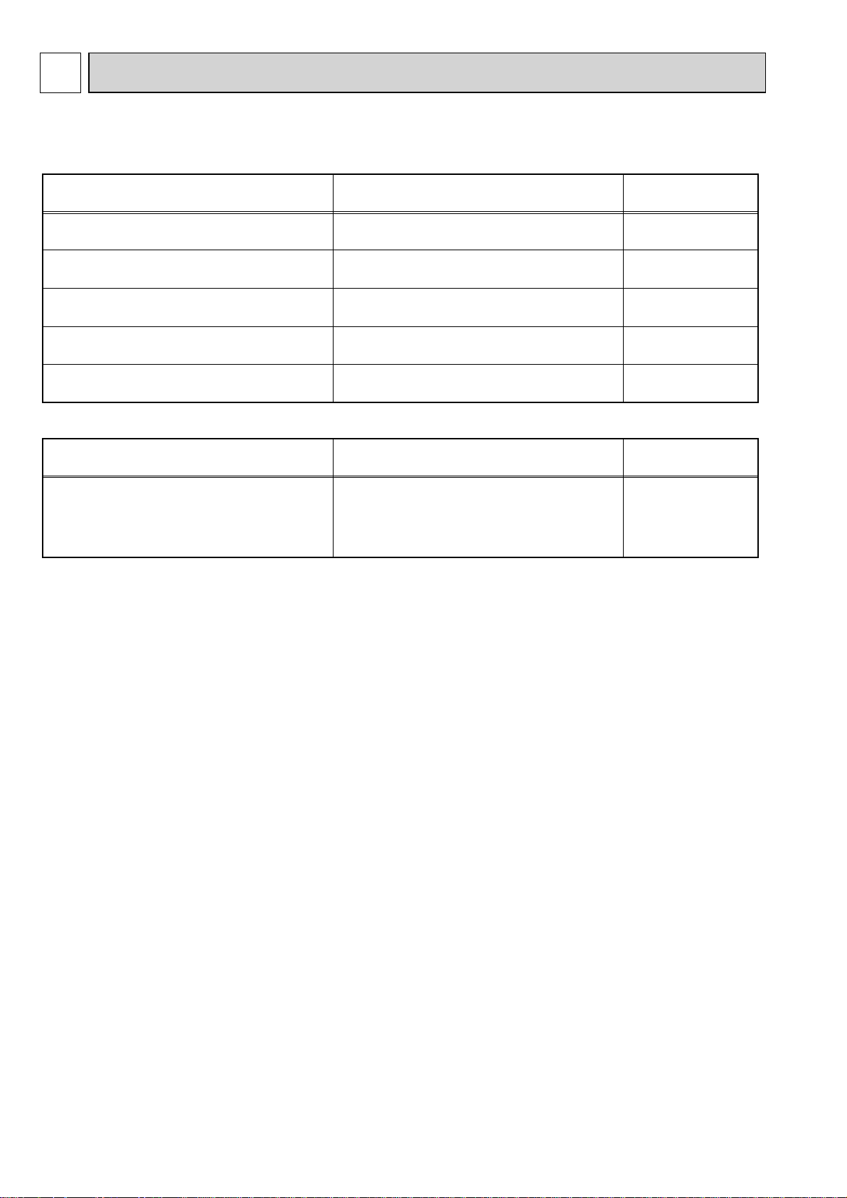
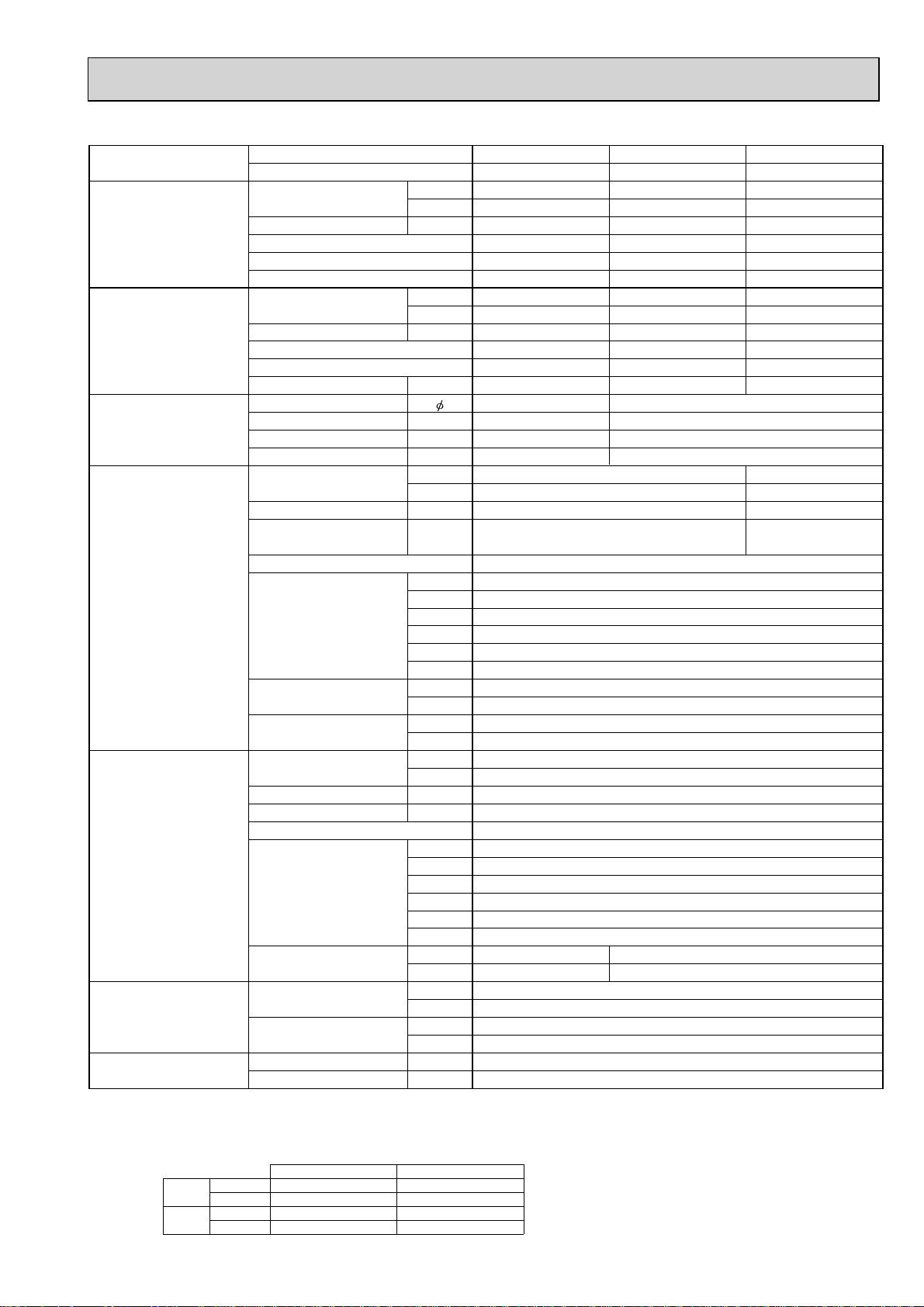
SPECIFICATIONS
2-1. CEILING CASSETTE TYPE
Model name Indoor unit
Outdoor unit
Cooling Capacity Btu/h
kW
Total input kW
EER
Energy label class
SHF
Heating Capacity Btu/h
kW
Total input kW
COP
Energy label class
Booster heater kW
Power supply Phase
Cycle Hz
Voltage V
Breaker size A
Indoor unit Air flow CMM
Outdoor unit Air flow CMM
Refrigerant pipe size Gas side O.D. mm
Refrigerant pipe length
NOTE: 1. Rating conditions (ISO T1)
Cooling Indoor : D.B. 27°C (80°F) W.B. 19°C (66°F) Outdoor : D.B. 35°C (95°F) W.B. 24°C (75°F)
Heating Indoor : D.B. 20°C (68°F) Outdoor : D.B. 7°C (45°F) W.B. 6°C (43°F)
Refrigerant piping length (one way) : 5m (16ft.)
2. Guaranteed operating range
Cooling
Heating
(Low-Medium2-Medium1-High)
External pressure Pa
Sound level
(Low-Medium2-Medium1-High)
External finish (Panel)
Dimension W : mm
Unit (Panel) D : mm
Weight kg
Unit (Panel) lbs
Field drain pipe O.D. mm
Sound level at cooling
Sound level at heating
External finish
Dimension W : mm
Weight kg
Liquid side O.D. mm
Height difference
Length
Upper limit
Lower limit
Upper limit
Lower limit
D.B. 32°C, W.B. 23°C
D.B. 19°C, W.B. 15°C D.B. -5°C *
D.B. 28°C
D.B. 17°C
Indoor Outdoor
CFM
dB(A)
H : mm
W : inch
D : inch
H : inch
inch
CFM
dB(A)
dB(A)
D : mm
H : mm
W : inch
D : inch
H : inch
lbs
inch
inch
m
m
D.B. 46°C
D.B. 21°C, W.B. 15°C
D.B. -25°C, W.B. -25°C
PLA-RP71BA2 PLA-RP100BA2
PUHZ-HRP71VHA2 PUHZ-HRP100VHA2
24,200 34,100
7.1 ( 4.9 - 8.1 ) 10.0 ( 4.9 - 11.4 )
1.94 2.44
3.66 4.10
AA
0.73 0.74
27,300 38,200
8.0 ( 4.5 - 10.2 ) 11.2 ( 4.5 - 14.0 )
1.90 2.54
4.21 4.41
AA
-1
50
230
32 40
14 - 16 - 18 - 21
495 - 565 - 635 - 740
0
White Munsell 6.4Y 8.9/0.4
840 (950)
840 (950)
33-1/16 (37-3/8)
33-1/16 (37-3/8)
10-3/16 (1-3/8) 11-3/4 (1-3/8)
23 (6)
51 (13)
32
1-1/4
100
3,530
51
52
Ivory Munsell 3Y 7.8/1.1
950
330+30
1350
37-3/8
13 + 1-3/16
53-1/8
120
265
15.88
5/8
9.52
3/8
Max. 30
Max. 75
3. Guaranteed voltage
198~264V, 50Hz
4. Above data are based on the indicated voltage.
Indoor unit Single phase 230V 50Hz
Outdoor unit
* If optional air protect guide is installed : D.B.-18°C
Single phase 230V 50Hz
20 - 23 - 26 - 30
710 - 810 - 920 - 1060
32 - 34 - 37 - 4028 - 30 - 32 - 34
298 (35)258 (35)
27 (6)
60 (13)
3
Page 4
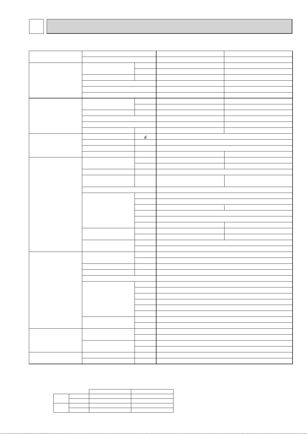
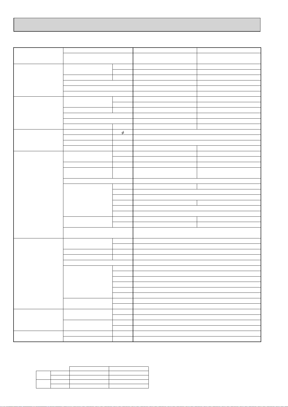
Model name Indoor unit
Outdoor unit
Cooling Capacity Btu/h
kW
Total input kW
EER
Energy label class
SHF
Heating Capacity Btu/h
kW
Total input kW
COP
Energy label class
Booster heater kW
Power supply Phase
Cycle Hz
Voltage V
Breaker size A
Indoor unit Air flow CMM
(Low-Medium2-Medium1-High)
CFM
External pressure Pa
Sound level
(Low-Medium2-Medium1-High)
dB(A)
External finish (Panel)
Dimension W : mm
Unit (Panel) D : mm
H : mm
W : inch
D : inch
H : inch
Weight kg
Unit (Panel) lbs
Field drain pipe O.D. mm
inch
Outdoor unit Air flow CMM
CFM
Sound level at cooling
Sound level at heating
dB(A)
dB(A)
External finish
Dimension W : mm
D : mm
H : mm
W : inch
D : inch
H : inch
Weight kg
lbs
Refrigerant pipe size Gas side O.D. mm
inch
Liquid side O.D. mm
inch
Refrigerant pipe length
NOTE: 1. Rating conditions (ISO T1)
Cooling Indoor : D.B. 27°C (80°F) W.B. 19°C (66°F) Outdoor : D.B. 35°C (95°F) W.B. 24°C (75°F)
Heating Indoor : D.B. 20°C (68°F) Outdoor : D.B. 7°C (45°F) W.B. 6°C (43°F)
Refrigerant piping length (one way) : 5m (16ft.)
2. Guaranteed operating range
Cooling
Heating
Height difference
Length
Upper limit
Lower limit
Upper limit
Lower limit
m
m
D.B. 32°C, W.B. 23°C
D.B. 19°C, W.B. 15°C D.B. -5°C *
D.B. 28°C
D.B. 17°C
Indoor Outdoor
D.B. 46°C
D.B. 21°C, W.B. 15°C
D.B. -25°C, W.B. -25°C
PLA-RP100BA2 PLA-RP125BA2
PUHZ-HRP100YHA2 PUHZ-HRP125YHA2
34,100 42,700
10.0 ( 4.9 - 11.4 ) 12.5 ( 5.5 - 14.0 )
2.50 3.79
4.00 3.30
AA
0.74 0.71
38,200 47,800
11.2 ( 4.5 - 14.0 ) 14.0 ( 5.0 - 16.0 )
2.60 3.57
4.31 3.92
AA
-3
50
400
16
20 - 23 - 26 - 30 22 - 25 - 28 - 31
710 - 810 - 920 - 1060 780 - 880 - 990 - 1090
00
32 - 34 - 37 - 40 34 - 36 - 39 - 41
White Munsell 6.4Y 8.9/0.4
840 (950)
840 (950)
298 (35)
33-1/16 (37-3/8)
33-1/16 (37-3/8)
11-3/4 (1-3/8)
27 (6)
60 (13)
32
1-1/4
100
3,530
51
52
Ivory Munsell 3Y 7.8/1.1
950
330+30
1350
37-3/8
13 + 1-3/16
53-1/8
134
295
15.88
5/8
9.52
3/8
Max. 30
Max. 75
3. Guaranteed voltage
198~264V, 50Hz(HRP100, 125Y : 342~457V, 50Hz)
4. Above data are based on the indicated voltage.
Indoor unit Single phase 230V 50Hz
Outdoor unit
* If optional air protect guide is installed : D.B.-18°C
3 phase 400V 50Hz
4
Page 5
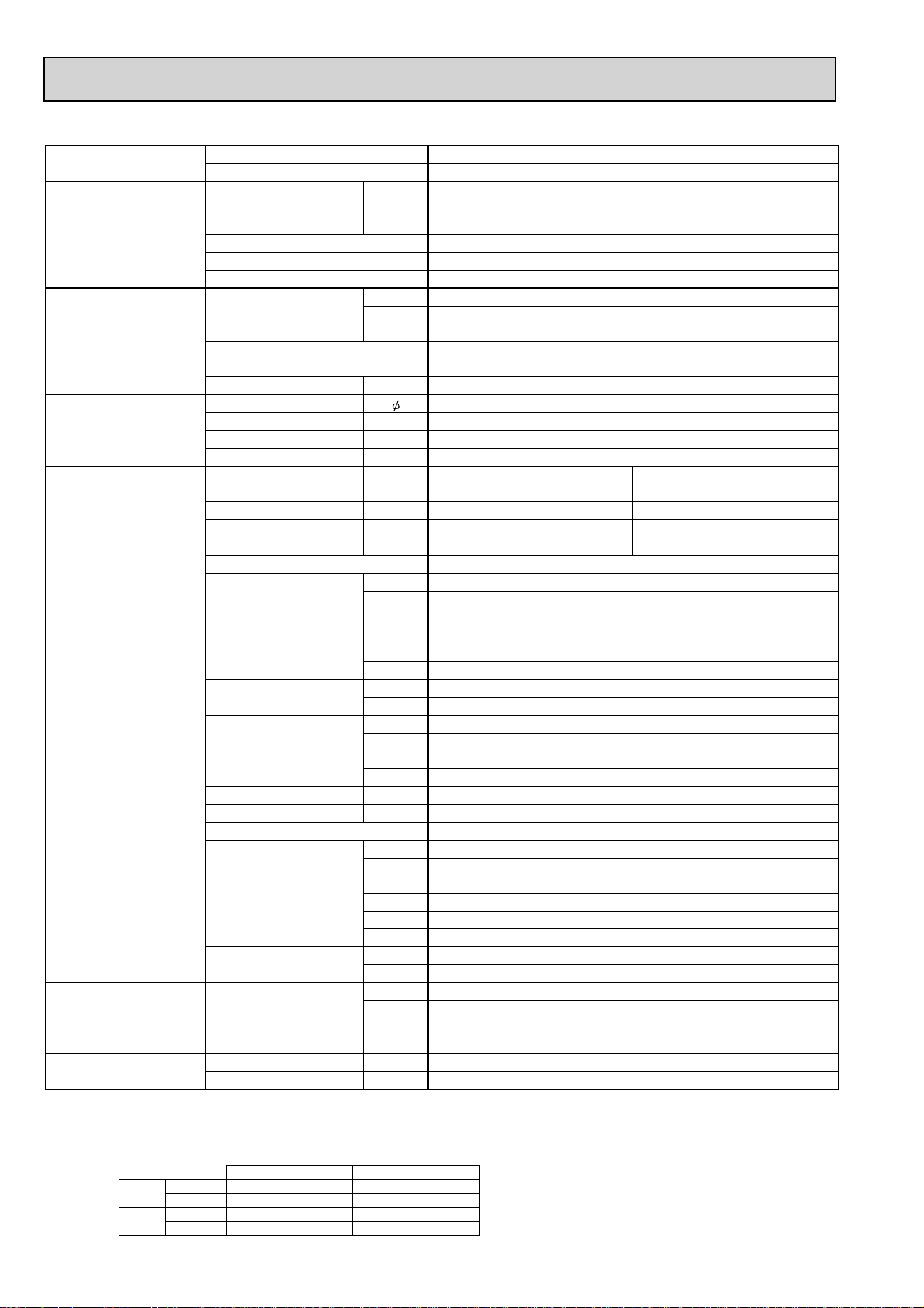
Model name Indoor unit
Outdoor unit
Cooling Capacity Btu/h
kW
Total input kW
EER
Energy label class
SHF
Heating Capacity Btu/h
kW
Total input kW
COP
Energy label class
Booster heater kW
Power supply Phase
Cycle Hz
Voltage V
Breaker size A
Indoor unit Air flow CMM
(Low-Medium2-Medium1-High)
CFM
External pressure Pa
Sound level
(Low-Medium2-Medium1-High)
dB(A)
External finish (Panel)
Dimension W : mm
Unit (Panel) D : mm
H : mm
W : inch
D : inch
H : inch
Weight kg
Unit (Panel) lbs
Field drain pipe O.D. mm
inch
Outdoor unit Air flow CMM
CFM
Sound level at cooling
Sound level at heating
dB(A)
dB(A)
External finish
Dimension W : mm
D : mm
H : mm
W : inch
D : inch
H : inch
Weight kg
lbs
Refrigerant pipe size Gas side O.D. mm
inch
Liquid side O.D. mm
inch
Refrigerant pipe length
NOTE: 1. Rating conditions (ISO T1)
Cooling Indoor : D.B. 27°C (80°F) W.B. 19°C (66°F) Outdoor : D.B. 35°C (95°F) W.B. 24°C (75°F)
Heating Indoor : D.B. 20°C (68°F) Outdoor : D.B. 7°C (45°F) W.B. 6°C (43°F)
Refrigerant piping length (one way) : 5m (16ft.)
2. Guaranteed operating range
Cooling
Heating
Height difference
Length
Upper limit
Lower limit
Upper limit
Lower limit
m
m
D.B. 32°C, W.B. 23°C
D.B. 19°C, W.B. 15°C D.B. -5°C *
D.B. 28°C
D.B. 17°C
Indoor Outdoor
D.B. 46°C
D.B. 21°C, W.B. 15°C
D.B. -25°C, W.B. -25°C
PLA-RP100BA PLA-RP100BA PLA-RP125BA
PUHZ-HRP100VHA PUHZ-HRP100YHA PUHZ-HRP125YHA
34,100 34,100 42,700
10.0 ( 4.9 - 11.4 ) 10.0 ( 4.9 - 11.4 ) 12.5 ( 5.5 - 14.0 )
3.02 3.02 3.87
3.31 3.31 3.23
AAA
0.74 0.74 0.71
38,200 38,200 47,800
11.2 ( 4.5 - 14.0 ) 11.2 ( 4.5 - 14.0 ) 14.0 ( 5.0 - 16.0 )
3.10 3.10 3.88
3.61 3.61 3.61
AAA
---
13
50 50
230 400
32 16
20 - 23 - 26 - 30 22 - 25 - 28 - 31
710 - 810 - 920 - 1060 780 - 880 - 990 - 1090
00
32 - 34 - 37 - 40 34 - 36 - 39 - 41
White Munsell 6.4Y 8.9/0.4
840 (950)
840 (950)
298 (35)
33-1/16 (37-3/8)
33-1/16 (37-3/8)
11-3/4 (1-3/8)
25 (6)
55 (13)
32
1-1/4
100
3,530
52
53
Ivory Munsell 3Y 7.8/1.1
950
330+30
1350
37-3/8
13 + 1-3/16
53-1/8
120 134
265 295
15.88
5/8
9.52
3/8
Max. 30
Max. 75
3. Guaranteed voltage
198~264V, 50Hz(HRP100, 125Y : 342~457V, 50Hz)
4. Above data are based on the indicated voltage.
Indoor unit Single phase 230V 50Hz
Outdoor unit
* If optional air protect guide is installed : D.B.-18°C
V:Single phase 230V 50Hz, Y:3 phase 400V 50Hz
5
Page 6
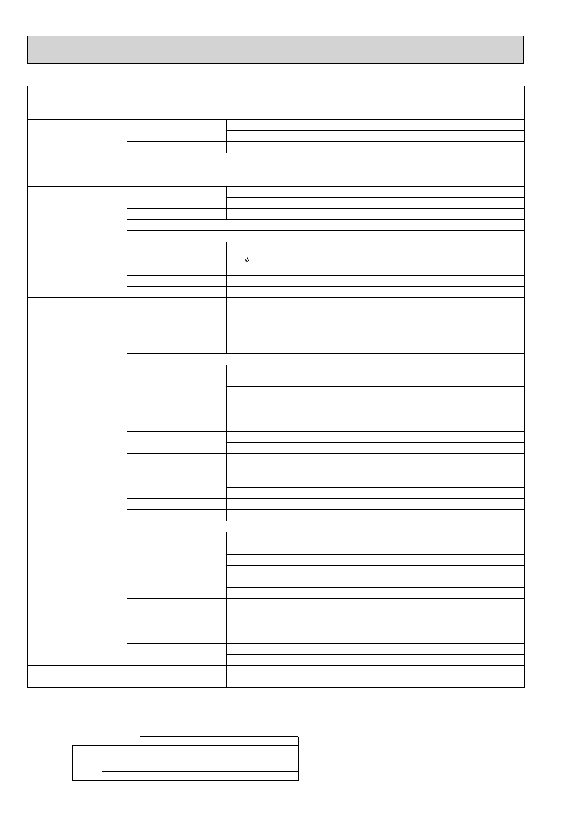
2-2. CEILING-CONCEALED TYPE
Model name Indoor unit
Outdoor unit
Cooling Capacity Btu/h
kW
Total input kW
EER
Energy label class
SHF
Heating Capacity Btu/h
kW
Total input kW
COP
Energy label class
Booster heater kW
Power supply Phase
Cycle Hz
Voltage V
Breaker size A
Indoor unit Air flow CMM
(Low-High)
CFM
External pressure Pa
Sound level
(Low-High)
dB(A)
External finish (Panel)
Dimension W : mm
Unit (Panel) D : mm
H : mm
W : inch
D : inch
H : inch
Weight kg
Unit (Panel) lbs
Unit drain pipe O.D.
PEAD-RP71EA PEAD-RP100EA2
PUHZ-HRP71VHA PUHZ-HRP100VHA
PUHZ-HRP71VHA2 PUHZ-HRP100VHA2
24,200 34,100
7.1 (4.9 - 8.1 ) 10.0 ( 4.9 - 11.4 )
2.15 3.06
3.30 3.27
AA
0.83 0.86
27,300 38,200
8.0 ( 4.5 - 10.2 ) 11.2 ( 4.5 - 14.0 )
2.34 3.10
3.42 3.61
BA
-1
50
230
32 (VHA)/ 40 (VHA2)32
20 - 25 33.5 - 42
706 - 883 1183 - 1483
70 70
37-41 44-50
Galvanized sheets
1175 1415
740
325
46-1/8 55-11/16
29-1/8
12-13/16
44 65
97 143
R1 (External thread)
Outdoor unit Air flow CMM
CFM
Sound level at cooling
Sound level at heating
dB(A)
dB(A)
External finish
Dimension W : mm
D : mm
H : mm
W : inch
D : inch
H : inch
Weight kg
lbs
Refrigerant pipe size Gas side O.D. mm
inch
Liquid side O.D. mm
inch
Refrigerant pipe length
NOTE: 1. Rating conditions (ISO T1)
Cooling Indoor : D.B. 27°C (80°F) W.B. 19°C (66°F) Outdoor : D.B. 35°C (95°F) W.B. 24°C (75°F)
Heating Indoor : D.B. 20°C (68°F) Outdoor : D.B. 7°C (45°F) W.B. 6°C (43°F)
Refrigerant piping length (one way) : 5m (16ft.)
2. Guaranteed operating range
Cooling
Heating
Height difference
Length
Upper limit
Lower limit
Upper limit
Lower limit
m
m
D.B. 32°C, W.B. 23°C
D.B. 19°C, W.B. 15°C D.B. -5°C *
D.B. 28°C
D.B. 17°C
Indoor Outdoor
D.B. 46°C
D.B. 21°C, W.B. 15°C
D.B. -25°C, W.B. -25°C
100
3,530
52 (VHA)/ 51 (VHA2)
53 (VHA)/ 52 (VHA2)
Ivory Munsell 3Y 7.8/1.1
950
330+30
1350
37-3/8
13 + 1-3/16
53-1/8
120
265
15.88
5/8
9.52
3/8
Max. 30
Max. 75
3. Guaranteed voltage
198~264V, 50Hz
4. Above data are based on the indicated voltage.
Indoor unit Single phase 230V 50Hz
Outdoor unit
* If optional air protect guide is installed : D.B.-18°C
Single phase 230V 50Hz
6
Page 7
Model name Indoor unit
Outdoor unit
Cooling Capacity Btu/h
kW
Total input kW
EER
Energy label class
SHF
Heating Capacity Btu/h
kW
Total input kW
COP
Energy label class
Booster heater kW
Power supply Phase
Cycle Hz
Voltage V
Breaker size A
Indoor unit Air flow CMM
(Low-High)
CFM
External pressure Pa
Sound level
(Low-High)
dB(A)
External finish (Panel)
Dimension W : mm
Unit (Panel) D : mm
H : mm
W : inch
D : inch
H : inch
Weight kg
Unit (Panel) lbs
Unit drain pipe O.D.
PEAD-RP100EA2 PEAD-RP125EA
PUHZ-HRP100YHA PUHZ-HRP125YHA
PUHZ-HRP100YHA2 PUHZ-HRP125YHA2
34,100 42,700
10.0 ( 4.9 - 11.4 ) 125. ( 5.5 - 14.0 )
3.06 3.89
3.27 3.21
AA
0.86 0.82
38,200 47,800
11.2 ( 4.5 - 14.0 ) 14.0 ( 5.0 - 16.0 )
3.10 3.88
3.61 3.61
AA
-3
50
400
16
33.5 - 42 33.5 - 42
1183 - 1483 1183 - 1483
70 70
44 - 50 44 - 50
Galvanized sheets
1415
740
325
55-11/16
29-1/8
12-13/16
65
143
R1 (External thread)
Outdoor unit Air flow CMM
CFM
Sound level at cooling
Sound level at heating
dB(A)
dB(A)
External finish
Dimension W : mm
D : mm
H : mm
W : inch
D : inch
H : inch
Weight kg
lbs
Refrigerant pipe size Gas side O.D. mm
inch
Liquid side O.D. mm
inch
Refrigerant pipe length
NOTE: 1. Rating conditions (ISO T1)
Cooling Indoor : D.B. 27°C (80°F) W.B. 19°C (66°F) Outdoor : D.B. 35°C (95°F) W.B. 24°C (75°F)
Heating Indoor : D.B. 20°C (68°F) Outdoor : D.B. 7°C (45°F) W.B. 6°C (43°F)
Refrigerant piping length (one way) : 5m (16ft.)
2. Guaranteed operating range
Cooling
Heating
Height difference
Length
Upper limit
Lower limit
Upper limit
Lower limit
m
m
D.B. 32°C, W.B. 23°C
D.B. 19°C, W.B. 15°C D.B. -5°C *
D.B. 28°C
D.B. 17°C
Indoor Outdoor
D.B. 46°C
D.B. 21°C, W.B. 15°C
D.B. -25°C, W.B. -25°C
100
3,530
52 (YHA)/ 51 (YHA2)
53 (YHA)/ 52 (YHA2)
Ivory Munsell 3Y 7.8/1.1
950
330+30
1350
37-3/8
13 + 1-3/16
53-1/8
134
295
15.88
5/8
9.52
3/8
Max. 30
Max. 75
3. Guaranteed voltage
Indoor unit:198~264V, 50Hz Outdoor unit:342~457V, 50Hz
4. Above data are based on the indicated voltage.
Indoor unit Single phase 230V 50Hz
Outdoor unit
* If optional air protect guide is installed : D.B.-18°C
3 phase 400V 50Hz
7
Page 8
Model name Indoor unit
Outdoor unit
Cooling Capacity Btu/h
kW
Total input kW
EER
Energy label class
SHF
Heating Capacity Btu/h
kW
Total input kW
COP
Energy label class
Booster heater kW
Power supply Phase
Cycle Hz
Voltage V
Breaker size A
Indoor unit Air flow CMM
(Low-High)
CFM
External pressure Pa
Sound level
(Low-High)
dB(A)
External finish (Panel)
Dimension W : mm
Unit (Panel) D : mm
H : mm
W : inch
D : inch
H : inch
Weight kg
Unit (Panel) lbs
Unit drain pipe O.D. mm
inch
Outdoor unit Air flow CMM
CFM
Sound level at cooling
Sound level at heating
dB(A)
dB(A)
External finish
Dimension W : mm
D : mm
H : mm
W : inch
D : inch
H : inch
Weight kg
lbs
Refrigerant pipe size Gas side O.D. mm
inch
Liquid side O.D. mm
inch
Refrigerant pipe length
NOTE: 1. Rating conditions (ISO T1)
Cooling Indoor : D.B. 27°C (80°F) W.B. 19°C (66°F) Outdoor : D.B. 35°C (95°F) W.B. 24°C (75°F)
Heating Indoor : D.B. 20°C (68°F) Outdoor : D.B. 7°C (45°F) W.B. 6°C (43°F)
Refrigerant piping length (one way) : 5m (16ft.)
2. Guaranteed operating range
Cooling
Heating
Height difference
Length
Upper limit
Lower limit
Upper limit
Lower limit
m
m
D.B. 32°C, W.B. 23°C
D.B. 19°C, W.B. 15°C D.B. -5°C *
D.B. 28°C
D.B. 17°C
Indoor Outdoor
D.B. 46°C
D.B. 21°C, W.B. 15°C
D.B. -25°C, W.B. -25°C
PEAD-RP71GA PEAD-RP100GA PEAD-RP100GA
PUHZ-HRP71VHA PUHZ-HRP100VHA PUHZ-HRP100YHA
PUHZ-HRP71VHA2 PUHZ-HRP100VHA2 PUHZ-HRP100YHA2
24,200 34,100 34,100
7.1 ( 4.9 - 8.1 ) 10.0 ( 4.9 - 11.4 ) 10.0 ( 4.9 - 11.4 )
2.15 3.08 3.08
3.30 3.25 3.25
AAA
0.83 0.86 0.86
27,300 38,200 38,200
8.0 ( 4.5 - 10.2 ) 11.2 ( 4.5 - 14.0 ) 11.2 ( 4.5 - 14.0 )
2.34 3.28 3.28
3.42 3.41 3.41
BBB
--13
50 50
230 400
32 (VHA)/ 40 (VHA2)32 16
20-25 26.5-33
706-883 935-1165
10/50/70 10/50/70
35-38/37-41/37-43 40-43/42-45/42-46
Galvanized sheets
1171 1411
740
275
46-1/8 55-9/16
29-1/8
10-13/16
42 50
93 111
R1 (External thread)
1-1/4
100
3,530
52 (VHA, YHA)/ 51 (VHA2, YHA2)
53 (VHA, YHA)/ 52 (VHA2, YHA2)
Ivory Munsell 3Y 7.8/1.1
950
330+30
1350
37-3/8
13 + 1-3/16
53-1/8
120 134
265 295
15.88
5/8
9.52
3/8
Max. 30
Max. 75
3. Guaranteed voltage
198~264V, 50Hz(HRP100Y : 342~457V, 50Hz)
4. Above data are based on the indicated voltage.
Indoor unit Single phase 230V 50Hz
Outdoor unit
* If optional air protect guide is installed : D.B.-18°C
V:Single phase 230V 50Hz, Y:3 phase 400V 50Hz
8
Page 9
Model name Indoor unit
Outdoor unit
Cooling Capacity Btu/h
kW
Total input kW
EER
Energy label class
SHF
Heating Capacity Btu/h
kW
Total input kW
COP
Energy label class
Booster heater kW
Power supply Phase
Cycle Hz
Voltage V
Breaker size A
Indoor unit Air flow CMM
(Low-High)
CFM
External pressure Pa
Sound level
(Low-High)
dB(A)
External finish (Panel)
Dimension W : mm
Unit (Panel) D : mm
H : mm
W : inch
D : inch
H : inch
Weight kg
Unit (Panel) lbs
Field drain pipe I.D.
mm
inch
Outdoor unit Air flow CMM
CFM
Sound level at cooling
Sound level at heating
dB(A)
dB(A)
External finish
Dimension W : mm
D : mm
H : mm
W : inch
D : inch
H : inch
Weight kg
lbs
Refrigerant pipe size Gas side O.D. mm
inch
Liquid side O.D. mm
inch
Refrigerant pipe length
NOTE: 1. Rating conditions (ISO T1)
Cooling Indoor : D.B. 27°C (80°F) W.B. 19°C (66°F) Outdoor : D.B. 35°C (95°F) W.B. 24°C (75°F)
Heating Indoor : D.B. 20°C (68°F) Outdoor : D.B. 7°C (45°F) W.B. 6°C (43°F)
Refrigerant piping length (one way) : 5m (16ft.)
2. Guaranteed operating range
Cooling
Heating
Height difference
Length
Upper limit
Lower limit
Upper limit
Lower limit
m
m
D.B. 32°C, W.B. 23°C
D.B. 19°C, W.B. 15°C D.B. -5°C *
D.B. 28°C
D.B. 17°C
Indoor Outdoor
D.B. 46°C
D.B. 21°C, W.B. 15°C
D.B. -25°C, W.B. -25°C
PKA-RP100FAL PKA-RP100FAL
PUHZ-HRP100VHA PUHZ-HRP100YHA
PUHZ-HRP100VHA2 PUHZ-HRP100YHA2
34,100 34,100
10.0 ( 4.9 - 11.4 ) 10.0 ( 4.9 - 11.4 )
2.93 2.93
3.41 3.41
AA
0.77 0.77
38,200 38,200
11.2 ( 4.5 - 14.0 ) 11.2 ( 4.5 - 14.0 )
3.10 3.10
3.61 3.61
AA
--
13
50 50
230 400
32 (VHA)/ 40 (VHA2) 16
22 - 28
780 - 990
0
41 - 46
White Munsell 3.4Y 7.7/0.8
1680
235
340
66-1/8
9-1/4
13-3/8
28
62
20
13/16
100
3,530
52
(VHA, YHA)/ 51 (VHA2, YHA2)
53 (VHA, YHA)/ 52 (VHA2, YHA2)
Ivory Munsell 3Y 7.8/1.1
950
330+30
1350
37-3/8
13 + 1-3/16
53-1/8
120 134
265 295
15.88
5/8
9.52
3/8
Max. 30
Max. 75
3. Guaranteed voltage
198~264V, 50Hz(HRP100Y : 342~457V, 50Hz)
4. Above data are based on the indicated voltage.
Indoor unit Single phase 230V 50Hz
Outdoor unit
* If optional air protect guide is installed : D.B.-18°C
V:Single phase 230V 50Hz, Y:3 phase 400V 50Hz
9
Page 10
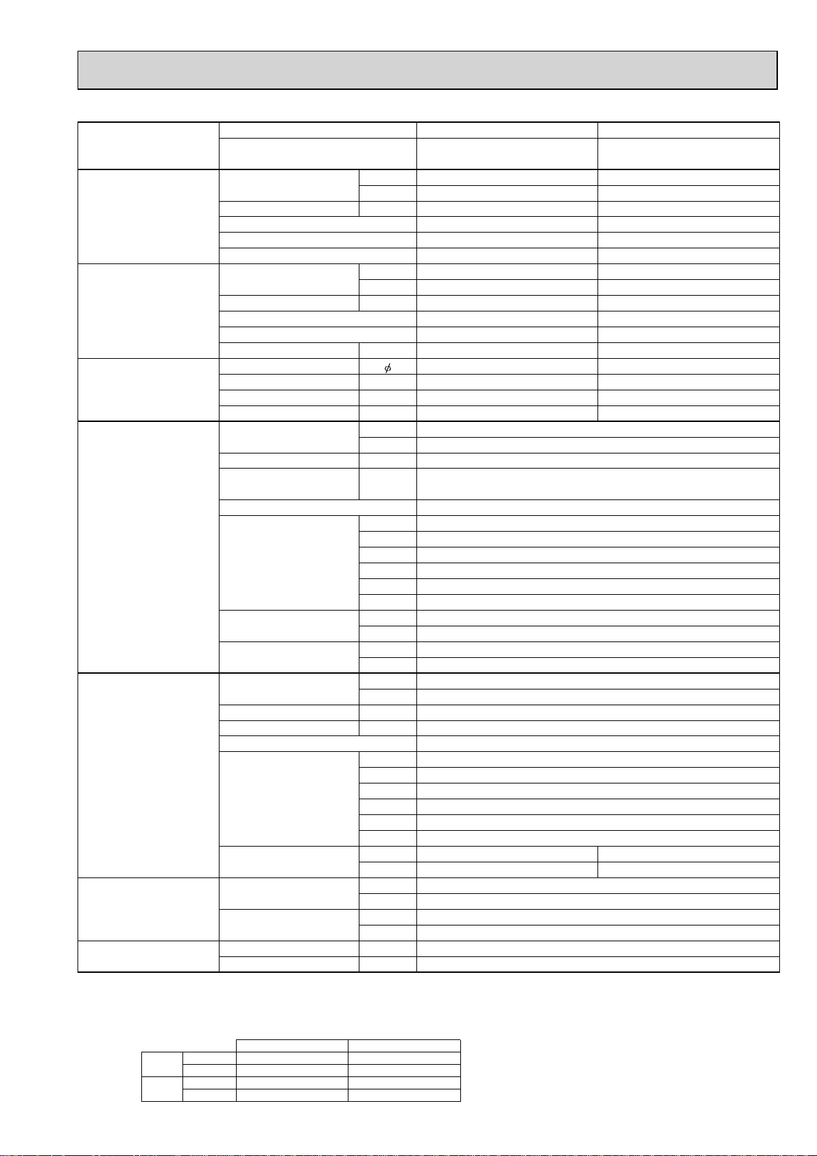
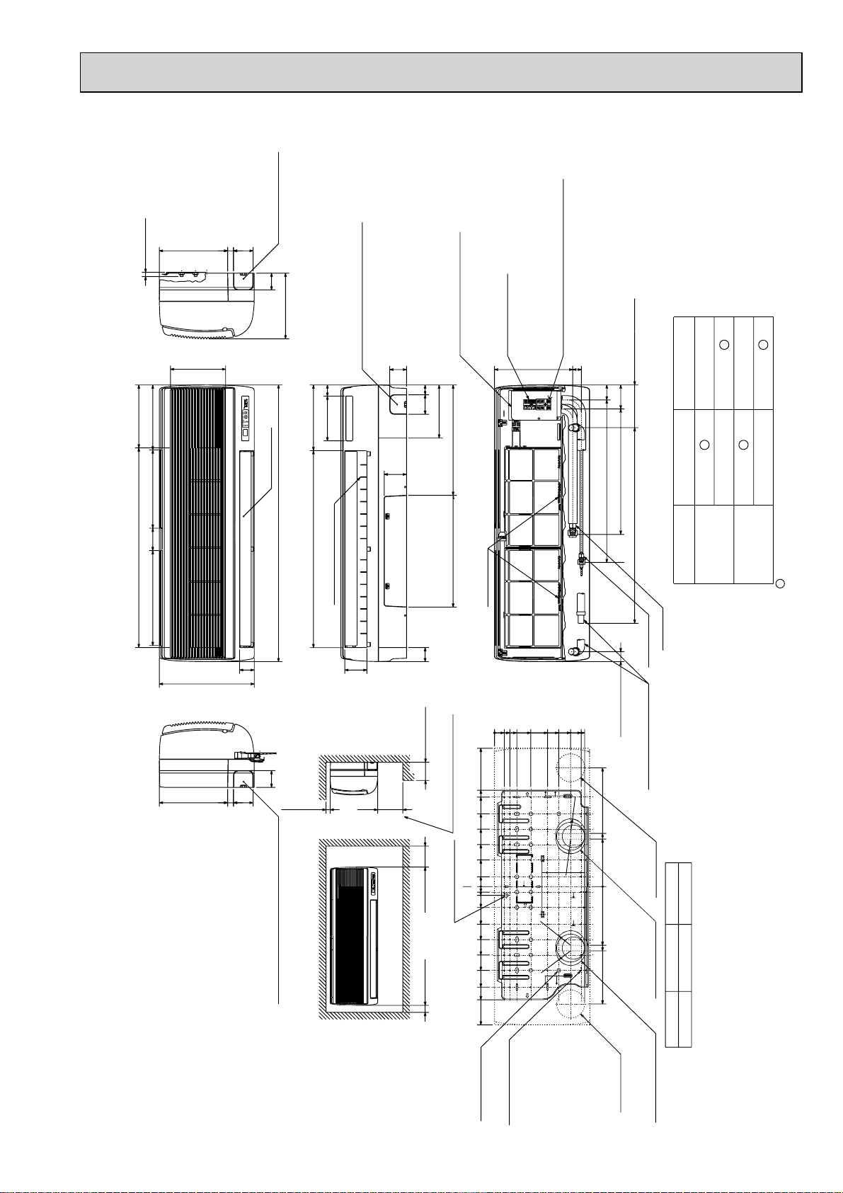
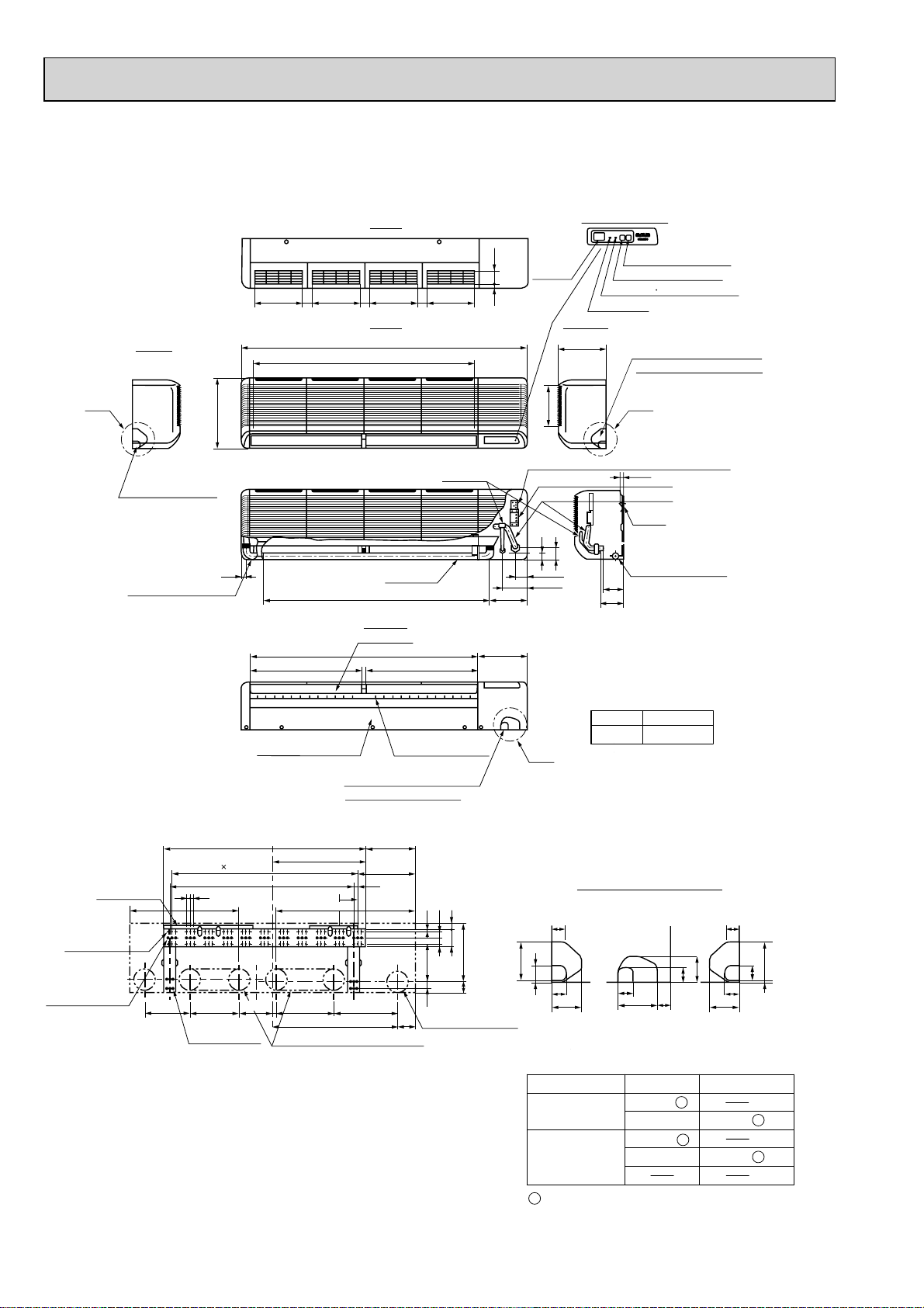
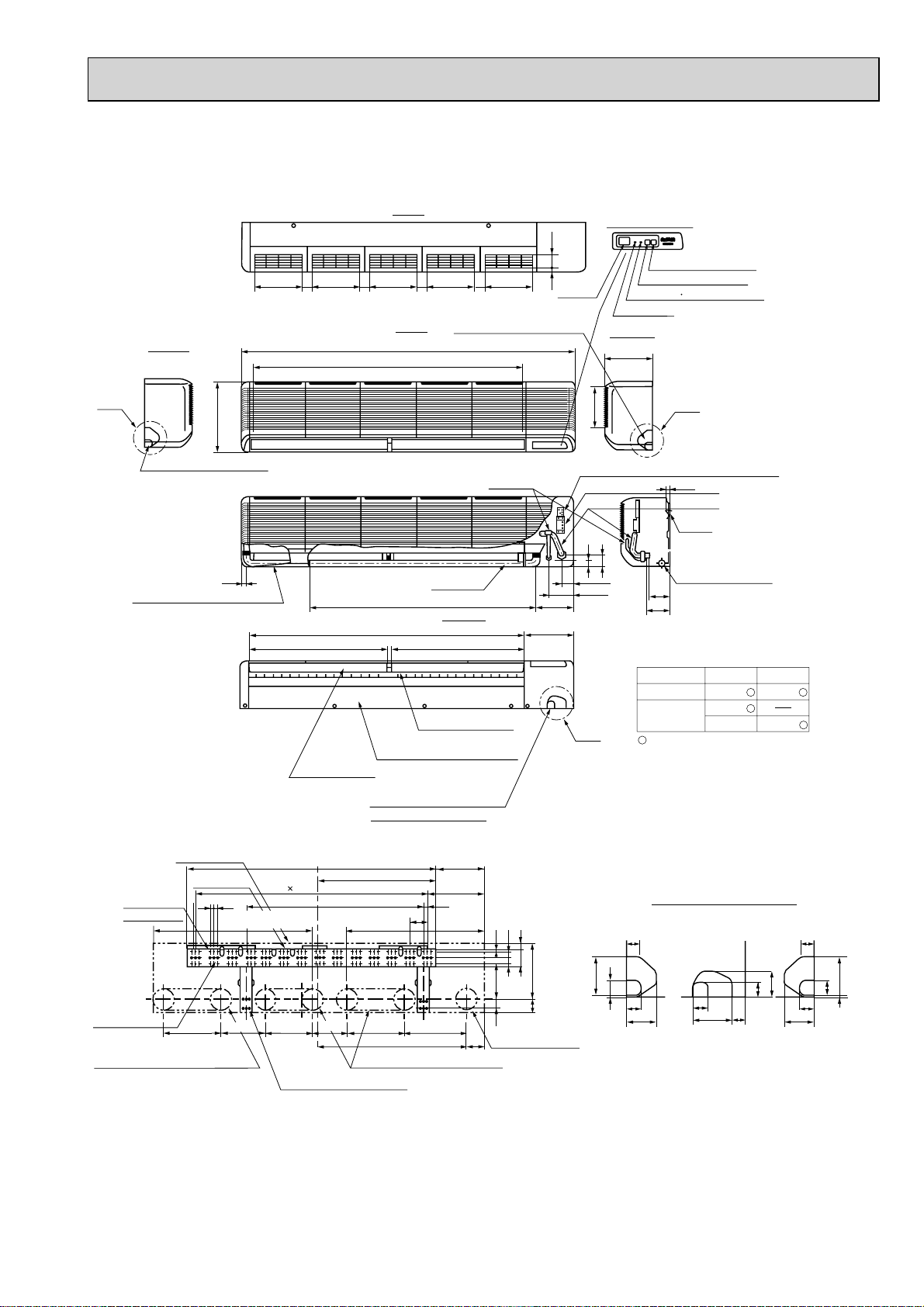
3
OUTLINES AND DIMENSIONS
INDOOR UNIT
Unit : mm
PLA-RP35BA PLA-RP50BA PLA-RP60BA PLA-RP100BA PLA-RP125BA
PLA-RP71BA2 PLA-RP100BA2 PLA-RP125BA2
Ceiling hole
860~910
810
Suspension bolt pitch
Indoor unit/Outdoor unit
connecting terminal block
Indoor power supply
terminal block(Option part)
840
Power supply wire,
Indoor unit/Outdoor unit
connecting wire entry
597
Air intake hole
M
500
Air outlet hole
950
3000mm or more
37728460
Indoor unit
160
Grille
M
M
83
1800mm or more
from floor
For high
attachment
20~45
Detail connecting of branch duct(Both aspects)
20~45
(7.5)(7.5)
+35
620
605
- 5
Suspension bolt pitch
24
160
Drain pipe
connected to VP-25
A
190
156
105
+
+
+
0
+5
Ceiling
Drain hole
Drain pump clean hole
and Drain emergency
drainage hole
597
Vane motor
36
17
Auto vane
(Air outlet)
Air intake hole
Note 1. Please choose the Grille from a standard grille or Auto-Grille.
2. As for drain pipe, please use VP-25(O.D. :32 PVC TUBE).
860~910
Ceiling hole
Branch duct hole
:175
Burring hole pitch
Detail drawing of fresh air intake hole
20~45
Connected the attached
flexible pipe or socket.
()
Keep approximately
10 to 15mm space
between unit ceiling
and ceiling slab.
B35
+
In case of standard grille : PLP-6BA / PLP-6BAMD
In case of Auto-Grille : PLP-6BAJ
In case of wireless remote controller : PLP-6BALM
Emergency operation
switch<Cooling>and
Emergency Up/Down switch<Up>
Emergency operation
switch<Heating>and
Emergency Up/Down switch<Down>
Receiver
Operation lamp
158
+
DEFROST/STAND BY lamp
Drain pump is included.
Max. lifting height is 850mm from the ceiling.
3. As for suspension bolt, please use M10 or W3/8. (Procured at local site)
4. Electrical box may be removed for the service purpose.
Make sure to slack the electrical wire little bit for control/ power wires connection.
5. The height of the indoor unit is able to be adjusted with the grille attached.
6. For the installation of the optional high efficiency filter or optional multi-functional casement.
1) Requires E or more space between transom and ceiling for the installation.
2) Add 135 mm to the dimensions + marked on the figure.
3) The optional high efficiency filter becomes optional multi-functional casement and concomitant use.
7. When installing the branch ducts, be sure to insulate adequately.
Otherwise condensation and dripping may occur. (It becomes the cause of dew drops/water dew.)
8. As for necessary installation/service space, please refer to the left figure.
Models
PLA-RP35/50BA
PLA-RP60BA
PLA-RP71BA
PLA-RP71BA2
PLA-RP100,125,140BA
PLA-RP100,125BA2
1
Refrigerant pipe
···:6.35
Flared connection
···1/4 inch
Refrigerant pipe
:6.35 / :9.52
Flared connection
1/4 inch / 3/8 inch
(compatible)
Refrigerant pipe
···:9.52
Flared connection
···3/8 inch
90 100 100 90
70
Burring hole
3-:2.8
120
2
Refrigerant pipe
···:12.7
Flared connection
···1/2 inch
Refrigerant pipe
···:15.88
Flared connection
···5/8 inch
Cut out hole
100
350
14-:2.8
Burring hole
:150
Cut out hole
Burring hole pitch
:125
Cut out hole
120
:100
Ceiling
Auto Grille
Air intake grille up/down discharge
L.L Filter
Ceiling
Air intake grille
BACDE
80
298
87
85 77
74
400
440
241 258
281
Branch duct hole
840
Suspension bolt
M10 or W3/8
Suspension bolt
lower edge
Air intake grille
Ceiling
Grille
1500mm
or more
Fresh air
intake hole
160
150
C
90
1
2
170
140
+
+
950
Indoor unit
Obstacle
20~45
D
50~70
+
Control wire entry
500
Air outlet hole
M
8336
1000mm
or more
160
Remote controller
terminal block
187.5
Floor
130
++
155
Max. 4.0m
167
10
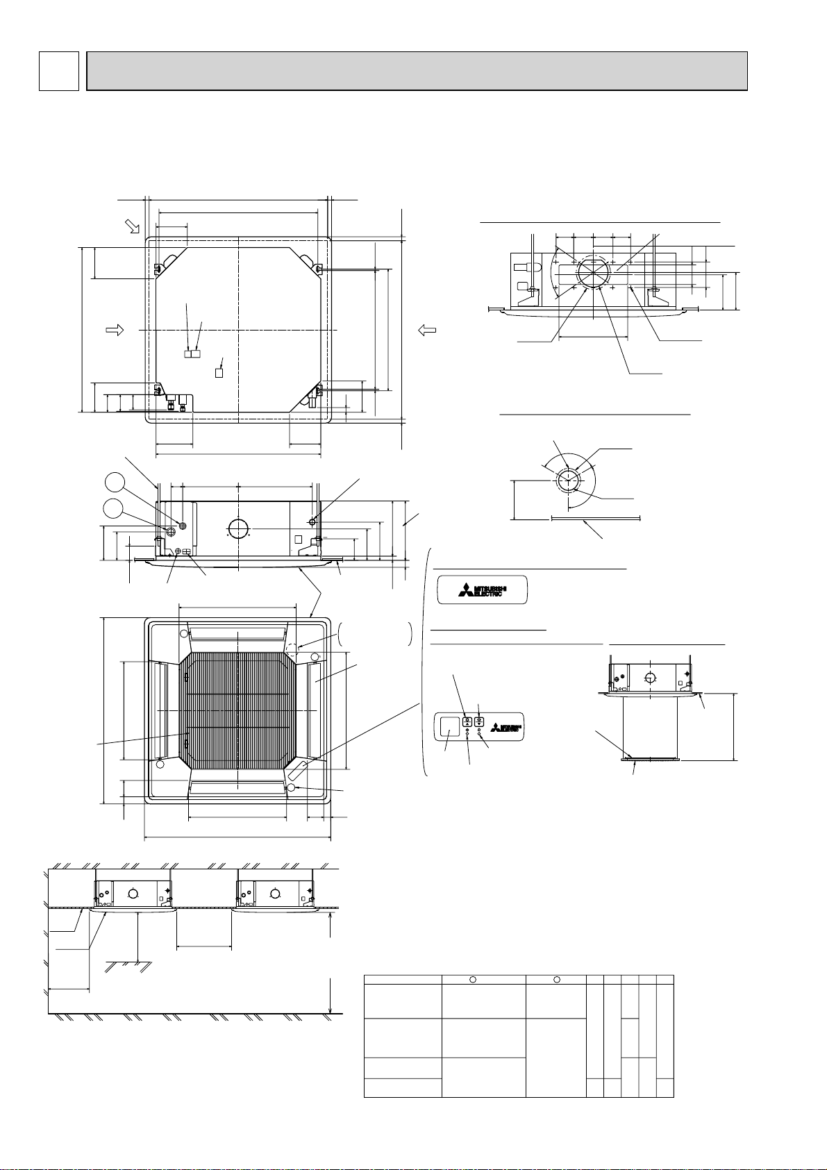
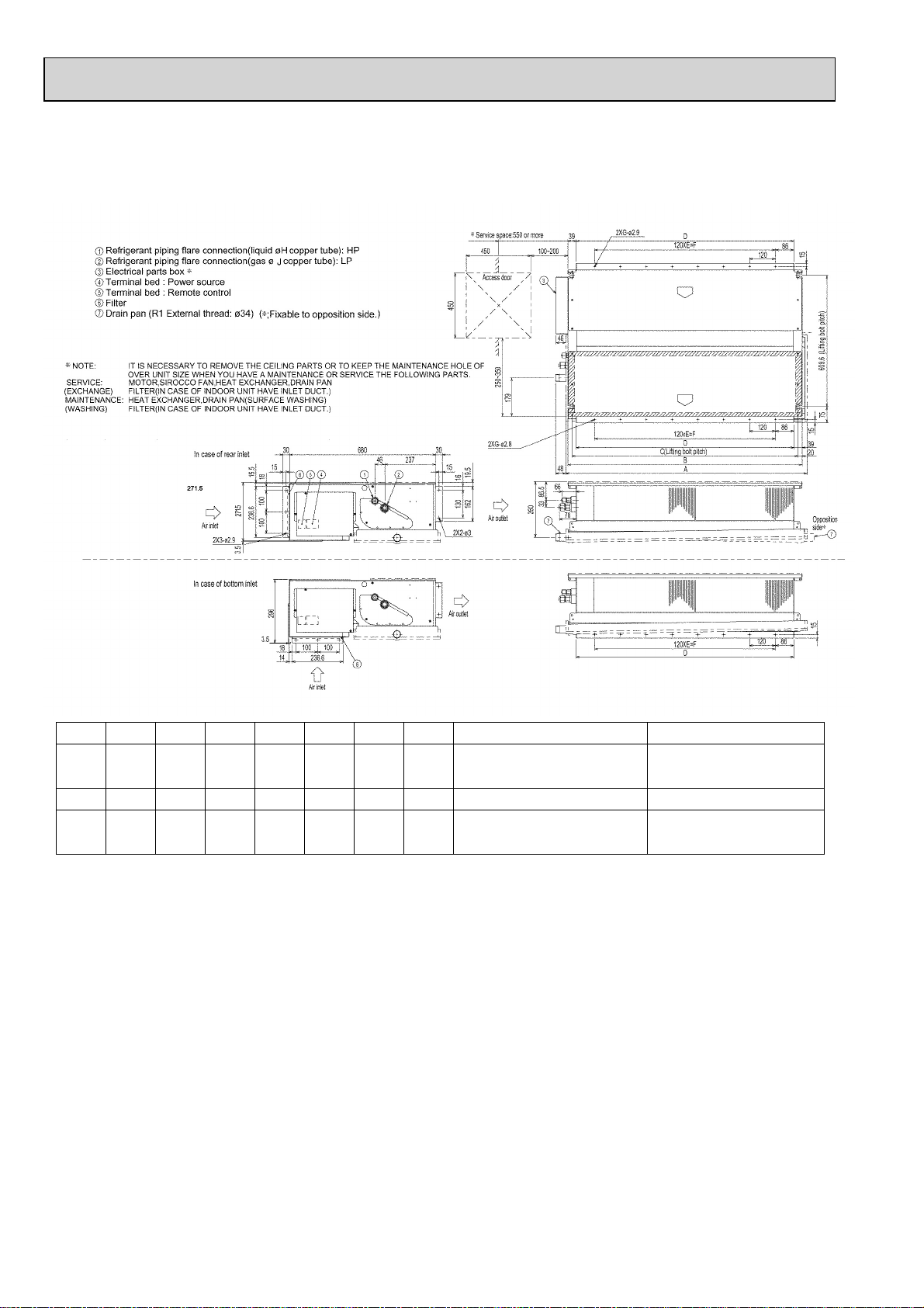
Page 11
PEAD-RP35EA2
PEAD-RP50EA
PEAD-RP60EA
Model
RP35,50
RP60
+ Initial setting
Refrigerant piping flare connection (liquid : F copper tube):HP
1
Refrigerant piping flare connection (gas :G copper tube):LP
2
Drain R1(External thread)
3
4
Electrical parts box
5
Drain Pump (Option)
6
Drain Pipe (Option) ... Flexible joint VP-25(I.D.
7
Filter
305772
In case of rear inlet
21
256
F
:
32)
30
4
10
40
282
176
EDCBA
-
Keep duct-work length 850mm or more.
Be sure to apply the air filter
near the air inlet grille.
R410A Outdoor unit : 6.35 +
804830
R407C Outdoor unit : 9.52
Outdoor unit (SUZ) : 6.35
104410702902801012
R407C Outdoor unit : 9.52 +
3.5
Air inlet
288
7
3.5
R410A Outdoor unit : 12.7 +
R407C Outdoor unit : 15.88
Set
61 227
1
2
450
G
15.88
Access door
30640
10
24
35
109
179
Air outlet
450
Service space:500 or more
50~150
55
197
365~465
159
18
13
75
44
243
6
85
80
45
277
5
3
Unit : mm
81BC
10-:3 (RP35,50)
12-:3 (RP60)
10
Lifting bolt hole
(1422)
56 355
10-:3 (RP35,50)
10
:
3 (RP60)
12-
13E
30
29
81
A
C
A
D
B 81
In case of bottom inlet
PEAD-RP71EA
PEAD-RP100EA2
PEAD-RP125EA
Model
RP71
RP100,125
+ Initial s
1
Refrigerant piping flare connection (liquid :9.52 copper tube):HP
2
Refrigerant piping flare connection (gas :F copper tube):LP
3
Drain R1 (External thread)
4
Electrical parts box
5
Drain Pump (Option)
6
Drain Pipe (Option) ... Flexible joint VP25(I.D.:32)
7
Filter
2801012
1252
etting
Air inlet
Keep duct-work length 850mm or more.
Be sure to apply the air filter
near the air inlet grille.
7
3.5
15
EDCBA
R410A Outdoor unit : 15.88 +
12841310370360
R407C outdoor unit : 19.05158416104704601552RP140
30
30
3.5
40
319
261
181
7
3.5
282
Air outlet
40
176
256
10
Air inlet
81
A
BC 81
10-:3 (RP35,50)
12-
:
3 (RP60)
10
Service space:500 or more
29
365~465
122
45
307
323
50~150
55
81
197
308
81
13
44
75
243
6
113
5
3
A
CB
C B81
A
E13
450
F
15.8810441070290
Access door
450
Set
680
4
30
1053 169
2
1
35
20
210
140
Air outlet
81
12-:3
10
Lifting bolt hole
(14x22)
375
12-:3
80
10
30D
11
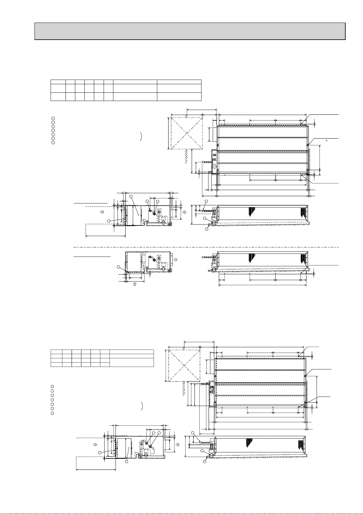
Page 12
PEAD-RP60GA
PEAD-RP71GA
PEAD-RP100GA
Unit : mm
Model A B C D E
RP60
RP71
RP100
*
Initial setting
1125
1125
1365
1090
1090
1330
1050
1050
1290
1012
1012
1252
FG H J
7
840
840
7
1080
9
8
8
10
Outdoor unit(SUZ) : 6.35
Other outdoor unit : 9.52
9.52
9.52
*
R410A Outdoor unit : 15.88 *
R407C Outdoor unit : 19.05
15.88
15.88
12
Page 13
PKA-RP35GAL PKA-RP50GAL Unit : mm
Knockout hole for
right piping
Refrigerant pipe.
Drain pipe.
Wiring hole
21
198
Air intake
70
60
235
Auto vane
Knockout hole for under piping
Refrigerant piping.Drain pipe.
Wiring hole
60
70 35
235
160 40
80
Service panel
(Power supply access)
Terminal block to
outdoor unit
190
395400
Terminal block for
power supply
(Heater (PKH-P35, 50GALH only))
31 280
installation)
(Right side piping
153
86
581 54
449
—
P35, 50
:6.35
RP35, 50
:9.52—:15.88
:9.52
:12.7
:15.88
Less than 15
Right side
Air intake
245
Air intake
715 225
Air intake
340 80 280 233
Front view
Left side
245
340
990
Air outlet
705
12-Louvers(manual)
53
21
70
Lower side
60
Right side
Knock out hole for left piping
Refrigerant pipe.Drain pipe.Wiring hole.
Allowing clearances
Front view
79
50
Less than 130
180 or more 30 or more
(Necessary clearance for
unit installation)
Unit center
Installation plate
balance point hole
50 or more 150 or more
Details of installation plate
Filter grip
Front view(to open the grille)
190
230
R52.5
5
R52.
272
R52.5
310
322
495
345
320
260
205
150
95
35
0
20
32
75
135
190
245
300
360
405
495
0355580130
0
R52.5
(Flexible hose total length800)
700
Use the current nuts meeting the pipe size of the outdoor unit.
Available pipe size
Gas pipe
Liquid pipe
installation)
(Left side piping
35
425
Unit drain pipe O.D.20
190
170
0
Right-rear
piping hole
210
230
Knockout hole for
right-rear piping
420
GAS SIDE
LIQUID SIDE
+1 Sleeves are available on the market.
+2 This size shows the lower end of through hole.
:90~:100:90
Through hole
: Initial flare nut size
Sleeve +1
35, 50
Model
13
for bolts
14-:14hole
49-:5hole
for tapping screw
Left-rear
piping hole
left-rear piping
Knockout hole for
Page 14
PKA-RP50FAL2 Unit : mm
PKA-RP60FAL
A
Left side
Knockout hole for
left piping
Drain hose for
left-hand side piping
340
25
235
552
45
Air outlet
235
1090
1110
To p
235
45
Front
1400
Air intake
Drain hose
Lower side
Auto vanes
1120
552
45
Air outlet
235
Liquid pipe
Display section
62.5
Receiving
section
13
Right side
235
197
Terminal block for indoor/outdoor connecting line
58
42
(Gas pipe)
55
120
183
(Liquid pipe)
Liquid pipe :9.52(3/8F)
240
Gas pipe :15.88(5/8F)
Emergency switch(Heat)
Emergency switch(Cool)
Defrosting Initial heating lamp
Power lamp
Knockout hole for right piping
Refrigerant pipe. Drain pipe
C
15
Bolt
107
111
Terminal block for heater (PKH only)
Gas pipe
Drain hose O.D.20
Wall fixture
66-ø6 hole for
tapping screw
32-ø12 hole for bolt
225
Under panel
Removable at left-hand
side piping
Unit center
990
10 91=(910)
900
18
18
Drainage range
on left-hand side
240 280 314
12-ø6 hole for
tapping screw
Drainage range
on right-hand side
180
Range for left rear piping opening
Knockout hole for under-piping
Refrigerant pipe. Drain pipe
245
455
285
19
91
610
Louvers (manual)
2980
10
3030
18430
90
Rear piping opening
280
60
Sleeve +1
:90
B
+1 Sleeves are available on the market.
Through hole
:90~ :100
Use the current nuts meeting
the pipe size of the outdoor unit.
Knockout hole for wiring
AB C
30
100
439
37
74
39
98
65
37
32
74
Available pipe size
RP60,71 / P60,71
:9.52
:15.88
LIQUID SIDE
GAS SIDE
RP50
:6.35
:9.52
:12.7
:15.88
30
100
39
37
4
14
: Initial flare nut size
Page 15
PKA-RP100FAL Unit : mm
Left side
A
340
Knockout hole for left piping
Drain hose for left-hand side piping
To p
Display section
62.5
Emergency switch(Heat)
235
235
45
235
45
235
45
Front
235
45
Knockout hole for right piping
Receiving
13
section
1680
Air intake
1370
197
Liquid pipe
Terminal block for indoor/outdoor connecting line
42
25
1400
Air outlet
694
1110
Drain hose
Drain hose
Lower side
Air outlet
694
183
240
(Gas pipe)
55
120
(Liquid pipe)
Emergency switch(Cool)
Defrosting Initial heating lamp
Power lamp
Right side
235
C
15
58
102
111
Terminal block for heater (PKH only)
Gas pipe
Bolt
Drain hose O.D.20
Available pipe size
Auto vane
Louvers (manual)
Under panel
(Removable at left-hand side piping)
Knockout hole for under-piping
Refrigerant pipe. Drain pipe
RP100
LIQUID SIDE
GAS SIDE
B
:Initial flare nut size
Use the current nuts meeting the pipe size
of the outdoor unit.
:9.52
:15.88
:19.05
P100
:9.52
:19.05
84-ø6 hole for
tapping screw
41-ø12 hole
for bolt
Unit out line
Wall fixture
18
18
Drainage range
on left-hand side
295 225
Unit center
1270
13 91=(1183)
240 280 314
595
900
Drainage range
on right-hand side
180
91
750
Range for left rear piping openingRange for left rear piping opening
12-ø6 hole for tapping screw
19
245
285
15
10
3030
18430
90
Rear piping opening
Knockout hole for wiring
2980
280
60
AB C
30
100
439
37
74
39
98
65
37
32
74
30
100
39
37
4
Page 16
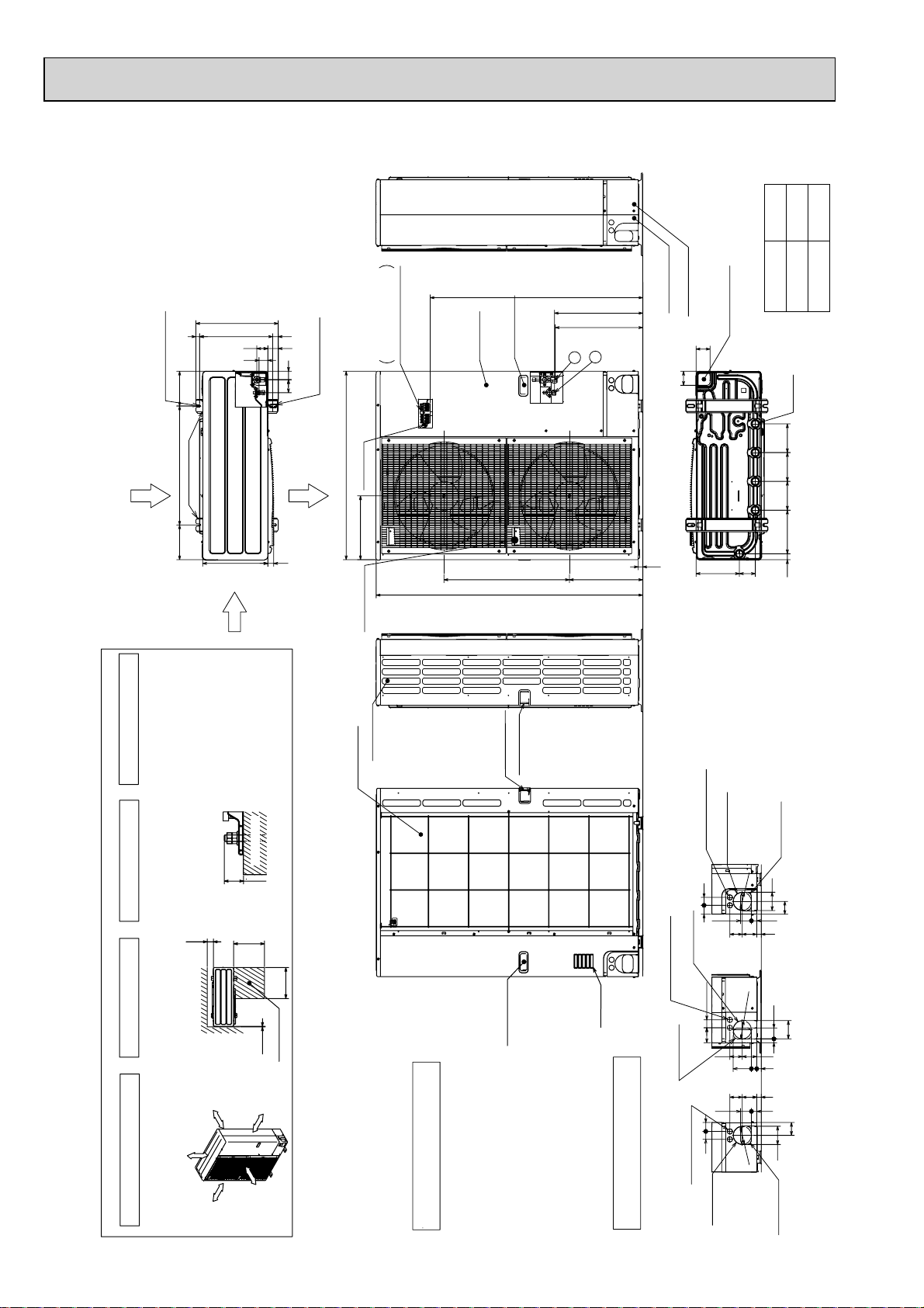
OUTDOOR UNIT Unit : mm
PUHZ-HRP71VHA
PUHZ-HRP100VHA
PUHZ-HRP100YHA
PUHZ-HRP125YHA
A
1,079
930
(19)
2-U Shaped notched holes
(Foundation Bolt M10)
600175 175
Rear Air Intake
Installation Feet
Side Air Intake
417
330
A
28 370
53 56
45
42
66
2-12 x 36 Oval holes
(Foundation Bolt M10)
Air Discharge
30
Terminal connection
950
Earth terminal
322
Left···Power supply wiring
Right···Indoor/Outdoor wiring
Service panel
Handle for moving
1350
+1 447
+1 443
2
1
371 635
Front piping cover
Rear piping cover
71
71
23
Bottom piping hole
(Knockout)
81 219
HRP·VHA
Drain hole
(5-W33)
14514522030 145
HRP·YHA
Handle for moving
Piping and wiring connections
can be made from 4 directions:
front, right, rear and below.
4 PIPING-WIRING DIRECTIONS
FOUNDATION
30
r 150mm
Ove
Over 10mm
Less than
500
Over
10
Over
Service space
Over 10mm
r 1000mm
Over
Ove
500
Please secure the unit firmly
with 4 foundation (M10) bolts.
3 FOUNDATION BOLTS
Dimensions of space needed
for service access are
2 SERVICE SPACE
The diagram below shows a
basic example.
1 FREE SPACE (Around the unit)
<Foundation bolt height>
(Bolts and washers must be
purchased locally.)
150
Over
shown in the below diagram.
FREE
Explantion of particular details are
given in the installation manuals etc.
Side Air Intake
Rear Air Intake
Handle for moving
Handle for moving
Handle for moving
···Refrigerant GAS pipe connction (FLARE)W15.88(5/8 inch)
···Refrigerant LIQUID pipe connection (FLARE)W 9.52(3/8 inch)
Example of Notes
+1 ···Indication of STOP VALVE connection location.
27Knockout)
W
Power supply wiring hole
(2-
Rear trunking hole
(Knockout)
92
W
45 40
Right trunking hole
(Knockout)
27Knockout)
W
Power supply wiring hole
Air intake
Piping Knockout Hole Details
40
(2-
75
Right piping hole
(Knockout)
45
40
27Knockout)
W
Power supply wiring hole
(2-
Front trunking hole
(Knockout)
92
W
27 92
73 63
92
W
Rear piping hole
(Knockout)
92
65
27 55
23 73 63
92
19 55
73 63
23
23
27 55
65
92
Front piping hole
(Knockout)
16
Page 17

PUHZ-HRP71VHA2
PUHZ-HRP100VHA2
PUHZ-HRP100YHA2
PUHZ-HRP125YHA2
Unit : mm
A
1,079
930
(19)28 370
175
(Foundation Bolt M10)
2-U Shaped notched holes
600175
Rear Air Intake
Installation Feet
Side Air Intake
417
330
A
2
Terminal connection
Right··· Indoor/Outdoor wiring
53 56
45
42
66
2-12 x 36 Oval holes
Air Discharge
30
Left ····Power supply wiring
(Foundation Bolt M10)
950
Earth terminal
322
Handle for moving
Service panel
Handle
for
moving
1
Handle for moving
635
1350
371
+1 447
+1 443
HRP·YHA2
Front piping cover
Rear piping cover
Bottom piping hole
(Knockout)
71
71
23
81 219
HRP·VHA2
Drain hole
(5- 33)
14514522030 145
Piping and wiring connections
front, right, rear and below.
can be made from 4 directions:
4 PIPING-WIRING DIRECTIONS
FOUNDATION
30
Over
Over 150mm
Less than
500
Over
10
Ove
500
Over
Service space
r 10mm
(Bolts and washers must be
shown in the below diagram.
purchased locally.)
150
Over
FREE
<Foundation bolt height>
Please secure the unit firmly
with 4 foundation (M10) bolts.
3 FOUNDATION BOLTS
Dimensions of space needed
for service access are
2 SERVICE SPACE
Side Air Intake
Rear Air Intake
Handle for moving
9.52(3/8 inch)
Handle for moving
Handle for moving
Power supply wiring hole
(2- 27Knockout)
Rear trunking hole
(Knockout)
40
45
Right trunking hole
(Knockout)
27Knockout)
Power supply wiring hole
(2-
Air intake
75 40
(Knockout)
Right piping hole
4540
27Knockout)
(2-
Power supply wiring hole
92
92
73 63
92
(Knockout)
Rear piping hole
92
65
27 55
23 73 63
92
19 55
73 63
23 27 92
23
27 55
65
92
given in the installation manuals etc.
basic example.
Explantion of particular details is
The diagram below shows a
1 FREE SPACE (Around the unit)
Over 10mm
Over 1000mm
···Refrigerant GAS pipe connction (FLARE) 15.88(5/8 inch)
···Refrigerant LIQUID pipe connection (FLARE)
Example of Notes
1 ···Indication of STOP VALVE connection location.
17
Piping Knockout Hole Details
(Knockout)
Front trunking hole
Front piping hole
(Knockout)
Page 18

4
WIRING DIAGRAM
4-1. INDOOR UNIT
PLA-RP35BA PLA-RP50BA PLA-RP60BA PLA-RP100BA PLA-RP125BA
[LEGEND]
SYMBOL SYMBOLNAME NAME SYMBOL NAME
I.B
DCL
DP
FS
<Table 1>SW1(MODEL SELECTION)
Manufacture/Service
INDOOR CONTROLLER BOARD
CN2L
CONNECTOR (LOSSNAY)
CN32
CONNECTOR (REMOTE SWITCH)
CONNECTOR (HA TERMINAL-A)
CN41
CN51
CONNECTOR (CENTRALLY CONTROL)
DSA
SURGE ABSORBER
FUSE
FUSE (T6.3AL250V)
LED1
POWER SUPPLY (I.B)
LED2
POWER SUPPLY (R.B)
LED3
TRANSMISSION (INDOOR-OUTDOOR)
SW1
SWITCH (MODEL SELECTION) +See table 1
SW2
SWITCH (CAPACITY CORD) +See table 2
SWE
CONNECTOR (EMERGENCY OPERATION)
X1
RELAY (DRAIN PUMP)
ZNR01,02
VAR IST OR
REACTOR
DRAIN-UP MACHINE
DRAIN FLOAT SWITCH
I.B
CNV(
WHT)
VAN E
18
20
19
3
CN3G
114169
(BLK)
5555
MV
GRILLE
WIRELESS
CN90
(WHT)
9
CNB
SW1
SW2
1 3
AUTO GRILLE
MMMM
MVMVMV
SW1
12345
ON
OFF
1234567891011121314151617
BZ
LED2
LED1
RU
W.B
MF
MV
TB2
TB4
TB5,TB6
TH1
TH2
TH5
Refer to tables 1 and 2.
2
1
TB6
R.B
SW2SW1
Pair No.
CN2L
LED3 LED2 LED1
I-SEE SENSOR
CN4Y
(WHT)
4 5
I-SEE
SENSOR
I-SEE SENSOR
CORNER PANEL
(OPTIONAL PART)
21
I-SEE
SENSOR MOTOR
CN6Y
(RED)
3
M
U.B
MT
CN3G
AUTOMATIC FILTER ELEVATION PANEL
(OPTIONAL PART)
<Table 2>SW2(CAPACITY CODE)
Manufacture/Service
MODELS
PLA-RP35BA
PLA-RP50BA
PLA-RP60BA
PLA-RP71BA
12345
12345
12345
12345
FAN MOTOR
VANE MOTOR
TERMINAL BLOCK (Indoor unit Power (option))
TERMINAL BLOCK (
TERMINAL BLOCK (REMOTE CONTROLLER
TRANSMISSION LINE)
ROOM TEMP. THERMISTOR
(0 / 15k, 25 / 5. 4k DETECT)
PIPE TEMP. THERMISTOR/LIQUID
(0 / 15k, 25 / 5. 4k DETECT)
COND. / EVA. TEMP. THERMISTOR
(0 / 15k, 25 / 5. 4k DETECT)
TRANSMISSION
WIRES
DC12V
J42J41
CN32
(WHT)
CN51(WHT)
51
CN41(WHT)
41
SWE
ON OFF
AUTO GRILLE
POWER
CNAC
(WHT)
31
FLOAT SW
FS
INDOOR/OUTDOOR CONNECTING LINE
TB5
2
1
113
CN4F
(WHT)
REMOCON
CN22
(BLU)
LIQUID/PIPE
CN44
(WHT)
14
4
tt t
TH2 TH5 TH1
3
1
INDOOR/OUTDOOR
COMMUNICATION
CN3C
(BLU)
21
INTAKE
CN20
(RED)
21
13135
CN3A
SW2
PLA-RP100BA
ON
OFF
PLA-RP125BA
ON
OFF
PLA-RP140BA
ON
OFF
ON
OFF
MODELS
Manufacture/Service
12345
12345
12345
OUTDOOR
CN01
(BLK)
DSA
ZNR02
DC280V
RECTIFICATION
FAN
CNMF
(WHT)
741
MS
3~
MF
OPTIONAL PART
)
135
U
U
ZNR01
X1
31
M
1~
DP
PCB FOR WIRELESS REMOTE CONTROLLER
W.B
BZ
BUZZER
LED1
LED (OPERATION INDICATION : GREEN)
LED2
LED (PREPARATION FOR HEATING : ORANGE)
RECEIVING UNIT
RU
SW1
EMERGENCY OPERATION (HEAT / DOWN)
SW2
EMERGENCY OPERATION (COOL / UP)
DCL
YLW
Please set the voltage using the
remote controller.
For the setting method, please refer to
the indoor unit Installation Manual.
TB4
YLW
YLW
ORN
ORN
BRN
ORN
S1
S2
S3
D.U.M
CNP
(BLU)
FUSE
+ Be sure to turn off the power source
and then disconnect fan motor connector.
(Failure to do so will cause trouble in Fan motor.)
+1(Fig. 1)
CN01
I.B
ON
OFF
ON
OFF
ON
OFF
I.B
(BLK)
5
3
1
CN3C
(BLU)
31
YLW
ORN
INDOOR/OUTDOOR
COMMUNICATION
RED
BLU
GRN/YLW
YLW
ORN
ORN
BRN
TB2
TB4
L
N
S1
S2
S3
POWER SUPPLY
~(1PHASE)
230V 50Hz
TO OUTDOOR UNIT
TO OUTDOOR
UNIT
Notes:
1. SymboIs used in wiring diagram above are, : Connector, : Terminal (block).
2. Indoor and outdoor connecting wires have poIarities, make sure to match terminal numbers (S1, S2, S3) for correct wirings.
3. Since the outdoor side electric wiring may change, be sure to check the outdoor unit electric wiring diagram for servicing.
4. This diagram shows the wiring of indoor and outdoor connecting wires (specification of 230V), adopting superimposed system of
power and signal.
+1: When supplying power separately to indoor and outdoor units, refer to Fig 1.
+2: For power supply system of this unit, refer to the caution label located near this diagram.
18
Page 19

PLA-RP71BA2 PLA-RP100BA2 PLA-RP125BA2
[LEGEND]
SYMBOL SYMBOLNAME NAME
I.B
DCL
DP
FS
M M M M
INDOOR CONTROLLER BOARD
CN2L
CONNECTOR (LOSSNAY)
CN32
CONNECTOR (REMOTE SWITCH)
CONNECTOR (HA TERMINAL-A)
CN41
CN51
CONNECTOR (CENTRALLY CONTROL)
DSA
SURGE ABSORBER
FUSE
FUSE (T6.3AL250V)
LED1
POWER SUPPLY (I.B)
LED2
POWER SUPPLY (R.B)
LED3
TRANSMISSION (INDOOR-OUTDOOR)
SW1
SWITCH (MODEL SELECTION) +See table 1
SW2
SWITCH (CAPACITY CODE) +See table 2
SWE
CONNECTOR (EMERGENCY OPERATION)
X1
RELAY (DRAIN PUMP)
ZNR01,02
VAR IST OR
REACTOR
DRAIN-UP MACHINE
DRAIN FLOAT SWITCH
<Table 2>SW2(CAPACITY CODE)
I.B
SW2
PLA-RP71BA2
PLA-RP100BA2
PLA-RP125BA2
VAN E
3
13
AUTO GRILLE
CN3G
1
(BLK)
5555
MVMVMVMV
GRILLE
Manufacture/ServiceMODELS
12345
12345
12345
CNV(
WHT)
1011121314151617181920
WIRELESS
CN90
(WHT)
9
CNB
SW1
SW2
RU
ON
OFF
ON
OFF
ON
OFF
BZ
LED2
LED1
W.B
123456789
LED3 LED2 LED1
I-SEE
SENSOR
CN4Y
(WHT)
9
14
I-SEE
SENSOR
I-SEE SENSOR
CORNER PANEL
(OPTION PART)
MF
MV
TB2
TB4
TB5,TB6
TH1
TH2
TH5
OPTION PART
W.B
Refer to tables 1 and 2.
SW2SW1
I-SEE
SENSOR MOTOR
CN6Y
(RED)
16
4
5
M
MT
FAN MOTOR
VANE MOTOR
TERMINAL BLOCK (Indoor unit Power (option))
TERMINAL BLOCK (
TERMINAL BLOCK (REMOTE CONTROLLER
TRANSMISSION LINE)
ROOM TEMP. THERMISTOR
(0 / 15kΩ, 25 / 5.4kΩ DETECT)
PIPE TEMP. THERMISTOR/LIQUID
(0 / 15kΩ, 25 / 5.4kΩ DETECT)
COND. / EVA. TEMP. THERMISTOR
(0 / 15kΩ, 25 / 5.4kΩ DETECT)
PCB FOR WIRELESS REMOTE CONTROLLER
BZ
BUZZER
LED1
LED (OPERATION INDICATION : GREEN)
LED2
LED (PREPARATION FOR HEATING : ORANGE)
RECEIVING UNIT
RU
SW1
EMERGENCY OPERATION (HEAT / DOWN)
SW2
EMERGENCY OPERATION (COOL / UP)
J42J41
Pair No.
CN2L
21
AUTO GRILLE
3
TRANSMISSION
WIRES
DC12V
CN32
(WHT)
CN51(
WHT)
51
CN41(
WHT)
41
SWE
ON
POWER
CNAC
(WHT)
131414
21
TB6
R.B
U.B
13315
CN3G
AUTOMATIC FILTER ELEVATION PANEL
(OPTION PART)
CN3A
Notes:
1.SymboIs used in wiring diagram above are,
:Connector, : : Terminal (block).
2.Indoor and outdoor connecting wires have poIarities, make sure to
match the terminal numbers (S1, S2, S3) for correct wirings.
3.Since the outdoor side electric wiring may change, be sure to check
the outdoor unit electric wiring for servicing.
4.This diagram shows the wiring of indoor and outdoor connecting
wires.(specification of 230V), adopting superimposed system of
power and signal.
+1:When work to supply power separately to indoor and outdoor
units was applied, refer to Fig 1.
+2:For power supply system of this unit, refer to the caution label
located near this diagram.
INDOOR/OUTDOOR CONNECTING LINE
<Table 1>SW1(MODEL SELECTION)
TB5
2
1
1123
OFF
FLOAT SW
CN4F
(WHT)
INDOOR/OUTDOOR
COMMUNICATION
REMOCON
CN22
(BLU)
LIQUID/PIPE
CN44
(WHT)
t¡ t¡ t¡
TH5TH2FS TH1
)
SW1
Manufacture/Service
12345
ON
OFF
13
CN3C
(BLU)
DC325V
RECTIFICATION
INTAKE
(RED)
FAN
CN20
CNMF
(WHT)
12 7 4 1
MS
OUTDOOR
ZNR02
3~
MF
CN01
(BLK)
DSA
U
DP
153
M
1~
U
ZNR01
X1
13
D.U.M
CNP
(BLU)
YLW
FUSE
DCL
YLW
ORN
ORN
BRN
YLW
ORN
+Be sure to turn off the power source
and then disconnect fan motor connector.
(Failure to do so will cause trouble in fan motor)
+1(Fig. 1
)
CN01
(BLK)
5
3
1
I.B
1
3
CN3C(BLU)
I.B
YLW
ORN
INDOOR/OUTDOOR
COMMUNICATION
RED
BLU
GRN/YLW
YLW
ORN
ORN
BRN
TB2
TB4
S1
S2
S3
L
N
POWER SUPPLY
~(1PHASE)
230V 50Hz
TO OUTDOOR UNIT
TB4
S1
S2
S3
TO OUTDOOR
UNIT
Please set the voltage using the
remote controller.
For the setting method, please refer to
the indoor unit Installation Manual.
19
Page 20

PEAD-RP35EA2 PEAD-RP50EA PEAD-RP60EA PEAD-RP71EA
PEAD-RP100EA2 PEAD-RP125EA
[LEGEND]
SYMBOL
I.B.
INDOOR CONTROLLER BOARD
FUSE
FUSE(T6.3AL250V)
ZNR
VAR IST OR
CN2L
CONNECTOR(LOSSNAY)
NAME
CN24 CONNECTOR(HEATER)
CN32
CONNECTOR(REMOTE SWITCH)
CN41
CONNECTOR(HA TERMINAL-A)
CN51
CONNECTOR(CENTRALLY CONTROL)
CONNECTOR(WIRELESS) DP
CN90
POWER SUPPLY(I.B.)
LED1
LED2
POWER SUPPLY(REMOTE CONTROLLER)
LED3
TRANSMISSION(INDOOR·OUTDOOR)
SW1
SWITCH(MODEL SELECTION)
TO MA-REMOTE
CONTROLLER
DC8.7-13V
TO OUTDOOR UNIT
WHT
BLK
SWITCH(CAPACITY CORD)
SW2
SWITCH(EMERGENCY OPERATION)
SWE
RELAY(DRAIN PUMP)
X1
RELAY(FAN MOTOR)
X4
RELAY(FAN MOTOR)
X5
RELAY(FAN MOTOR)
X6
P. B .
INDOOR POWER BOARD
DRAIN PUMP
(OPTIONAL PARTS)
DRAIN PUMP
DRAIN SENSOR
DS
C
CAPACITOR(FAN MOTOR)
MF
FAN MOTOR
TERMINAL BLOCKTB4
(INDOOR/OUTDOOR CONNECTING LINE)
TB5
TERMINAL BLOCK(REMOTE CONTROLLER)
TH1
INTAKE AIR TEMP. THERMISTOR
(0 /15), 25/5.4) DETECT)
TH2
PIPE TEMP. THERMISTOR/LIQUID
(0 /15), 25/5.4) DETECT)
TH5
COND./EVA. TEMP. THERMISTOR
(0 /15), 25/5.4) DETECT)
INSIDE SECTION OF CONTROL BOX
DS
TH5TH2TH1
1
SYMBOLSYMBOL
B
B
L
L
U
U
1
1
2
2
CN20 CN21 CN29
CN22
(RED)
(BLU)
1
2
CN2L
(RED)
LED1
LED2
LED3
2
CN2D
1
(WHT)
(BLU)
CN3C
(ORN)
CND
31
B
O
R
R
N
N
B
TB5
L
B
U
2
1
TB4
S3
BRN
ORN
S2
S1
YLW
+A
L
U
1
(WHT)
31
O
R
N
2
1
2
(BLK)
FUSE
Y
L
W
W
H
T
1
3
CN31
CN41
12
CN24
(YLW)
123456789 432145321
12
2
3
CN31
(WHT)
CN90
(WHT)
(WHT)
X1
ZNR
(RED)
CNDK
W
B
H
L
T
K
B
L
K
2
1
CN2S
(WHT)
W
H
T
B
L
K
31
P. B .
CNSK
(RED)
X1
(BLU)
CNP
1331
DP
Optional parts
<PEAD-RP35·50·60EA, 35EA2>
External static pressure 70Pa
(RED)
NAMENAME
CN51
(WHT)
CN32
(WHT)
SW1
SW2
SWE
X6X5X4
X5
X4
X6
1375
(WHT)
W
H
T
643521
FAN
P
P
B
N
N
L
K
K
K
<PEAD-RP35·50·60EA, 35EA2>
External static pressure 30Pa
<PEAD-RP71·100·125·140EA, 100EA2>
External static pressure 70Pa
643521
(WHT)
MF
C
I.B.
321
ON
OFF
Optional parts
643521
(RED)
MF
C
<PEAD-RP71·100·125·140EA, 100EA2>
External static pressure 130Pa
MODELS
35EA(2)
50EA
60EA
71EA
100EA(2)
125EA
140EA
SW1
Model selection
switch
54321
ON
OFF
SW2
Capacity cord
switch
12345
12345
12345
12345
12345
12345
12345
ON
OFF
ON
OFF
ON
OFF
ON
OFF
ON
OFF
ON
OFF
ON
OFF
<+A>
(IN CASE OF CONNECTING
THE REPLACEMENT WIRING)
POWER SUPPLY
L
~(1PHASE)
N
12
21
TO CND
12
TO CN3C
Notes:
1. SymboIs used in wiring diagram above are, : Connector, : Terminal (block).
2. Indoor and outdoor connecting wires have poIarities, make sure to match terminal
numbers (S1, S2, S3) for correct wirings.
3. Since the outdoor side electric wiring may change, be sure to check the outdoor unit
electric wiring diagram for servicing.
4. This diagram shows the wiring of indoor and outdoor connecting wires (specification
of 230V), adopting superimposed system of power and signal.
+1: When supplying power separately to indoor and outdoor units, refer to +A.
+2: For power supply system of this unit, refer to the caution label located near this diagram.
230V 50Hz
S1
S2
TO OUTDOOR
S3
UNIT
20
Page 21

PEAD-RP60GA PEAD-RP71GA PEAD-RP100GA
[LEGEND]
SYMBOL
I.B.
INDOOR CONTROLLER BOARD
FUSE
FUSE(T6.3AL250V)
ZNR
VAR ISTO R
CONNECTOR(LOSSNAY)
CN2L
CN24 CONNECTOR(HEATER)
CN32
CONNECTOR(REMOTE SWITCH)
CN41
CONNECTOR(HA TERMINAL-A)
CN51
CONNECTOR(CENTRALLY CONTROL)
CONNECTOR(WIRELESS)
CN90
POWER SUPPLY(I.B.)
LED1
LED2
POWER SUPPLY(REMOTE CONTROLLER)
LED3
TRANSMISSION(INDOOR·OUTDOOR)
NAME
WHT
BLK
B
L
U
CN22
(BLU)
LED1
LED2
LED3
2
1
B
L
U
1
CN2D
(WHT)
(BLU)
CN3C
O
R
N
2
31
1
2
CN20 CN21 CN29
(RED)
(WHT)
1
2
CN2L
(RED)
CND
O
B
R
R
N
N
SWITCH(MODEL SELECTION)
SW1
SWITCH(CAPACITY CORD)
SW2
SWITCH(EMERGENCY OPERATION)
SWE
RELAY(DRAIN PUMP)
X1
RELAY(FAN MOTOR)
X4
RELAY(FAN MOTOR)
X5
RELAY(FAN MOTOR)
X6
P. B .
INDOOR POWER BOARD
C
CAPACITOR(FAN MOTOR)
MF
FAN MOTOR
TB4
TERMINAL BLOCK
(INDOOR/OUTDOOR CONNECTING LINE)
INSIDE SECTION OF CONTROL BOX
TH5TH2TH1
1
1
2
31
Y
L
W
(BLK)
FUSE
12
2
3
123456789
CN31
(WHT)
CN90
(WHT)
X1
ZNR
CNDK
B
W
L
H
K
T
X1
(BLU)(RED)(ORN)
CNP
1331
CN41
(WHT)
321
4
SYMBOLSYMBOL
1
CN24
(YLW)
TERMINAL BLOCK(REMOTE CONTROLLER)
TB5
TH1
INTAKE AIR TEMP.THERMISTOR
(0 /15), 25/5.4) DETECT)
NAMENAME
TH2
PIPE TEMP. THERMISTOR/LIQUID
(0 /15), 25/5.4) DETECT)
TH5
COND./EVA. TEMP. THERMISTOR
(0 /15), 25/5.4) DETECT)
I.B.
2
CN51
(WHT)
G
R
Y
54321
X5
X4
5
Y
Y
L
L
W
W
21
3
CN32
(WHT)
SW1
SW2
SWE
ON
OFF
X6X5X4
X6
137
(WHT)
FAN
B
L
K
B
W
W
B
L
H
K
T
B
TB5
L
TO MA-REMOTE
CONTROLLER
DC8.7-13V
TO OUTDOOR UNIT
<+A>
(IN CASE OF CONNECT
THE REPLACEMENT WIRING)
12
21
TO CND
Notes:
1. SymboIs used in wiring diagram above are, : Connector, : Terminal (block).
2. Indoor and outdoor connecting wires have poIarities, make sure to match terminal numbers (S1, S2, S3) for correct wirings.
3. Since the outdoor side electric wiring may change, be sure to check the outdoor unit electric wiring diagram for servicing.
4. This diagram shows the wiring of indoor and outdoor connecting wires (specification of 230V), adopting superimposed system of
power and signal.
+1: When supplying power separately to indoor and outdoor units, refer to +A.
+2: For power supply system of this unit, refer to the caution label located near this diagram.
12
TO CN3C
2
1
TB4
S3
S2
S1
B
U
L
U
BRN
ORN
YLW
POWER SUPPLY
L
~(1PHASE)
N
230V 50Hz
S1
S2
TO OUTDOOR
S3
UNIT
+A
2
21
MODELS
100GA
1
CN2S
(WHT)
60GA
71GA
L
H
K
T
P. B .
13
CNSK
(RED)
Model selection
switch
54321
ON
OFF
SW2SW1
Capacity cord
switch
12345
12345
12345
ON
OFF
ON
OFF
ON
OFF
MF
O
B
B
R
L
L
G
K
U
C
*External static pressure
*
CONNECTOR COLOR
643521
(WHT)
BLU
WHT
(INITIAL SETTING)
RED
5Pa
35Pa
10Pa
50Pa
70Pa50Pa
240V230V220V
20Pa
60Pa
75Pa
21
Page 22

PKA-RP35GAL PKA-RP50GAL
[LEGEND]
SYMBOL NAME
P. B
I.B
INDOOR POWER BOARD
INDOOR CONTROLLER BOARD
FUSE FUSE (T6.3AL250V)
ZNR VARISTOR
CN2L CONNECTOR <LOSSNAY>
CN32 CONNECTOR <REMOTE SWITCH>
CN41 CONNECTOR <HA TERMINAL-A>
CN51 CONNECTOR <CENTRALLY CONTROL>
SW1 SWITCH <MODEL SELECTION>+See Table 1.
SW2 SWITCH <CAPACITY CODE>+See Table 2.
SWE SWITCH <EMERGENCY OPERATION>
X4 RELAY <FAN MOTOR>
BCR
FAN CONTROL ELEMENT
LED1 POWER SUPPLY <I.B>
POWER SUPPLY <R.B>
LED2
TRANSMISSION <INDOOR-OUTDOOR>LED3
P. B
CNDK
(RED)
1
MF
1
2 3
C
WHT
RED
I.B
1 3 5
FAN
(
)
WHT
BCR
SWE
ON
OFF
Refer to tables 1
and 2 for service PCB.
BLK
POWER
CNDK
(RED)
X4
X4
SW2 SW1
2
3
WHT
RED
LED3 LED2 LED1
PKH-P35,50GALH models only
HEATER
CN24
1
2
(YLW)
I.B
YLW
YLW
61
88H
26H
RED
6
REDGRY
5
DC13.1V
POWER
CND
(ORN)
ZNR
H1
SYMBOL NAME
C CAPACITOR <FAN MOTOR>
MF
MV
TB2
TB4
TB5,TB6
TH1
TH2
TH5
CN2S
(WHT)
FAN MOTOR
VANE MOTOR
TERMINAL BLOCK (HEATER) +PKH-P.GALH
models only or option for PKA-RP.GAL models.
TERMINAL BLOCK <INDOOR/ OUTDOOR
CONNECTING LINE>
TERMINAL BLOCK <REMOTE CONTROLLER
TRANSMISSION LINE> <OPTION>
ROOM TEMP.THERMISTOR
<0/ 15k, 25/ 5.4k DETECT>
PIPE TEMP.THERMISTOR/ LIQUID
<0/ 15k, 25/ 5.4k DETECT>
COND./ EVA.TEMP.THERMISTOR
<0/ 15k, 25/ 5.4k DETECT>
1
2
YLW
ORN
BLK
WHT
1 31 31 3 1 2
INDOOR/OUTDOOR
COMMUNICATION
CN3C(BLU)
CN41 CN2L
CN51 CN32
PIPE
CN29
)
(
BLK
1 2
TH2
1
WHT
2
GRN/YLW
)
TH5TH1
88H
FUSE
INTAKE
CN20
(
)
RED
1 2
FS1
POWER
CN2D(WHT)
LIQUID
CN21
(
WHT
1 2
FS2
TB4
YLW
ORN
ORN
BRN
VAN E
CN6V
(
GRN
WIRELESS
CN90
(
WHT
REMOCON
CN22
(
)
BLU
1 2
TB2
L
REDRED 5 3RED
N
BLU
W.B
RU
BZ
LED1
LED2
SW1
SW2
R.B
HEATER
FS1
FS2
H1
26H
88H
S1
TO
S2
OUTDOOR
S3
UNIT
MV
I.B
POWER
CND
(ORN)
6
)
)
2
TRANSMISSION WIRES DC12V
1
TB5
Please set the voltage using the
POWER SUPPLY
~(1PHASE)
230V 50Hz
remote controller.
For the setting method, please refer to
the indoor unit Installation Manual.
WIRELESS REMOTE CONTROLLER BOARD
RECEIVING UNIT
BUZZER
LED <RUN INDICATOR>
LED <HOT ADJUST>
SWITCH (HEATING ON/ OFF>
SWITCH (COOLING ON/ OFF>
WIRED REMOTE CONTROLLER BOARD
THERMAL FUSE <104
THERMAL FUSE <8410A>
HEATER
HEATER THERMAL SWITCH
HEATER CONTACTOR
NAMESYMBOL
10A>
+1 (Fig.1)
TB2
RED
BLU
GRN/YLW
TB4
YLW
ORN
ORN
YLW
ORN
BRN
L
N
S1
S2
S3
POWER
SUPPLY
~(1PHASE)
230V 50Hz
TO
OUTDOOR
UNIT
3131
INDOOR/OUTDOOR
COMMUNICATION
CN3C
(BLU)
9
CNB
BZ
RU
RECEIVER
LED1 LED2 SW2 SW1
W.B
R.B
1
TB6
2
SW1
Service board
1 2 3 4 5
Notes:
1. SymboIs used in wiring diagram above are, : Connector, : Terminal (block).
2. Indoor and outdoor connecting wires have poIarities, make sure to match terminal numbers (S1, S2, S3) for correct wirings.
3. Since the outdoor side electric wiring may change, be sure to check the outdoor unit electric wiring diagram for servicing.
4. This diagram shows the wiring of indoor and outdoor connecting wires (specification of 230V), adopting superimposed system of
power and signal.
+1: When supplying power separately to indoor and outdoor units, refer to Fig 1.
+2: For power supply system of this unit, refer to the caution label located near this diagram.
PKA-RP35GAL
ON
PKH-P35GALH
OFF
MODELS
Service board Service board
1 2 3 4 5
SW2
MODELS
PKA-RP50GAL
ON
PKH-P50GALH
OFF
1 2 3 4 5
ON
OFF
22
Page 23

PKA-RP50FAL2 PKA-RP60FAL PKA-RP100FAL
[LEGEND]
SYMBOL NAME
P. B
I.B
INDOOR POWER BOARD
INDOOR CONTROLLER BOARD
FUSE FUSE(T6.3AL250V)
ZNR VARISTOR
CN2L CONNECTOR(LOSSNAY)
CN32 CONNECTOR(REMOTE SWITCH)
CN41 CONNECTOR(HA TERMINAL-A)
CN51 CONNECTOR(CENTRALLY CONTROL)
SW1 SWITCH (MODEL SELECTION)
SW2 SWITCH (CAPACITY CODE)
SWE SWITCH(EMERGENCY OPERATION)
X4 RELAY(FAN MOTOR)
BCR
FAN CONTROL ELEMENT
LED1 POWER SUPPLY(I.B)
POWER SUPPLY(R.B)
LED2
TRANSMISSION(INDOOR-OUTDOOR)LED3
P. B
MF
1
2 3
C
BLK
WHT
RED
I.B
X4
POWER
CNDK
(RED)
FAN
(
WHT
BCR
1 3 5
)
X4
LED3 LED2 LED1
SW2 SW1
SWE
ON
OFF
Refer to tables 1
and 2 for service PCB.
Table 1
SW1
Service board
1 2 3 4 5
ON
OFF
+
See Table 1.
+
See Table 2.
CNDK
(RED)
1
DC13.1V
2
3
WHT
RED
POWER
CND
(ORN)
Table 2
MODELS
PKA-RP50FAL2
PKA-RP60FAL
PKH-P60FALH
SYMBOL NAME
C CAPACITOR(FAN MOTOR)
MF
MV
TB2
TB4
TB5
TH1
TH2
TH5
CN2S
(WHT)
FAN MOTOR
VANE MOTOR
TERMINAL BLOCK (HEATER)
models only or option for PKA-RP.FAL models.
TERMINAL BLOCK(INDOOR/OUTDOOR
CONNECTING LINE)
TERMINAL BLOCK(REMOTE CONTROLLER
TRANSMISSION LINE )(OPTION)
ROOM TEMP.THERMISTOR
/15k, 25/5.4k DETECT)
(0
PIPE TEMP.THERMISTOR/LIQUID
/15k, 25/5.4k DETECT)
(0
COND./EVA.TEMP.THERMISTOR
(0
/15k, 25/5.4k DETECT)
Please set the voltage
using the remote controller.
For the setting method,
1
2
please refer to the indoor
unit Installation Manual
+
PKH-P.FALH
W.B
RU
BZ
LED1
LED2
SW1
SW2
R.B
TB6
HEATER
FS1,2
H1
26H
88H
TB4
YLW
S1
TO
S2
YLW
ZNR
INTAKE
CN20
(
RED
1 2
ORN
BLK
POWER
CN2D(WHT)
FUSE
LIQUID
CN21
(
)
WHT
1 2
WHT
1 31 31 3 1 2
INDOOR/OUTDOOR
COMMUNICATION
CN3C(BLU)
CN41 CN2L
CN51 CN32
PIPE
CN29
)
(
)
BLK
1 2
ORN
ORN
BRN
VAN E
CN6V
(
)
GRN
WIRELESS
CN90
(
)
WHT
REMOCON
CN22
(
)
BLU
1 2
S3
OUTDOOR
UNIT
6
MV
I.B
YLW
POWER
CND
(ORN)
2
TRANSMISSION WIRES DC12V
TH2
TH5TH1
1
TB5
SW2
Service board Service board Service board
1 2 3 4 5
PKA-RP71FAL
ON
PKH-P71FALH
OFF
MODELS
1 2 3 4 5
MODELS
PKA-RP100FAL
ON
PKH-P100FALH
OFF
PKH-P60 P100FALH models only
RED
BLU
GRN/YLW
YLW
ORN
ORN
BRN
NAMESYMBOL
10A:60,71FALH/
TB2
L
N
TB4
S1
S2
S3
POWER
SUPPLY
(1PHASE)
230V 50Hz
TO
OUTDOOR
UNIT
WIRELESS REMOTE CONTROLLER BOARD
RECEIVING UNIT
BUZZER
LED(RUN INDICATOR )
LED(HOT ADJUST)
SWITCH(HEATING ON/OFF)
SWITCH(COOLING ON/OFF)
WIRED REMOTE CONTROLLER BOARD(OPTION)
TERMINAL BLOCK(REMOTE CONTROLLER
TRANSMISSION LINE)
THERMAL FUSE(117
117
16A:100FALH)
HEATER
HEATER THERMAL SWITCH
HEATER CONTACTOR
+
1 (Fig.1)
ORN
3131
INDOOR/OUTDOOR
COMMUNICATION
CN3C
(BLU)
9
CNB
BZ
RU
RECEIVER
1 2 3 4 5
LED1 LED2 SW2 SW1
R.B
ON
OFF
1
2
W.B
TB6
HEATER
CN24
1
2
I.B
Notes:
1. SymboIs used in wiring diagram above are, : Connector, : Terminal (block).
2. Indoor and outdoor connecting wires have poIarities, make sure to match terminal numbers (S1, S2, S3) for correct wirings.
3. Since the outdoor side electric wiring may change, be sure to check the outdoor unit electric wiring diagram for servicing.
4. This diagram shows the wiring of indoor and outdoor connecting wires (specification of 230V), adopting superimposed system of
power and signal.
+1: When supplying power separately to indoor and outdoor units, refer to Fig 1.
+2: For power supply system of this unit, refer to the caution label located near this diagram.
(YLW)
YLW
YLW
61
88H
26H
RED
6
REDGRY
5
H1
FS1
FS2
WHT
REDRED 5 3RED
BLU
TB2
L
N
POWER SUPPLY
(1PHASE)
230V 50Hz
88H
1
2
GRN/YLW
23
Page 24

4-2. OUTDOOR UNIT
PUHZ-HRP71VHA PUHZ-HRP100VHA
[LEGEND]
SYMBOL
TB1
MC
MF1, MF2
21S4
63H
63L Low Pressure Switch
SV
TH3,TH32,TH33
TH4
TH6
TH7
TH8
LEV-A, LEV-B,LEV-C
DCL
ACTM
CB
CY1,CY2
Terminal Block<Power Supply, Indoor/Outdoor>
Motor for Compressor
Fan Motor
Solenoid Valve (Four-Way Valve)
High Pressure Switch
Solenoid Valve (Bypass Valve)
Thermistor<Outdoor Pipe>
Thermistor<Discharge>
Thermistor<Outdoor 2-Phase Pipe>
Thermistor<Outdoor>
Thermistor<Heatsink>
Electronic Expansion Valve
Reactor
Active Filter Module
Main Smoothing Capacitor
Capacitor
NAME SYMBOL NAME SYMBOL NAME
P. B.
TABU/V/W
TABS/T
TABP1/P2/P
TABN1/N2/N
DS2, DS3
IPM
N.F.
LI / LO
NI / NO
EI, E2
52C
C.B.
SW1
SW4
SW5
Power Circuit Board
Connection Terminal<U/V/W-Phase>
Connection Terminal <L/N-Phase>
Connection Terminal<DC Voltage>
Connection Terminal<DC Voltage
Diode Bridge
Power Module
Noise Filter Circuit Board
Connection Terminal<L-Phase>
Connection Terminal<N-Phase>
Connection Terminal<Ground>
52C Relay
Controller Circuit Board
<Forced Defrost, Defect History Record
Switch
Reset, Refrigerant Address>
Switch<Test Operation>
Switch<Function Switch>
SW6
SW7
SW8
SW9
>
SWP
CN31
SS
CNM
CNMNT
CNVMNT
CNDM
LED1,LED2
F1~F4
X51,X52,X55
Switch<Model Select>
Switch<Function Setup>
Switch<Function Setup>
Switch
Switch<Pump Down>
Connector<Emergency Operation>
Connector<Connection for Option>
Connector
<A-Control Service Inspection Kit
Connector
<Connected to Optional M-NET Adapter Board
Connector
<Connected to Optional M-NET Adapter Board
Connector
< Connected for Option (Contact Input)>
LED<Operation Inspection Indicators>
Fuse< T6.3AL250V>
Relay
>
>
>
MF1
MF2
MS
3~
MS
3~
C. B.
1
1
LEV-C
M
LEV-B
5
6
1
LEV-B
(RED)
13 13 13
X52
5
1
LEV-C
(BLU)
CNVMNT
(WHT)
6
SV21S4
3
31
CNM
(WHT)
X55
SV2
(BLU)
5
CNMNT
(WHT)
CN52C
(RED)
221
+1+
1
51
SW5SW8SW4 SWP
SW6SW1
141
CN31
X51
SS
(WHT)
31
CN2
(WHT)
63L
63L
(RED)
7
31
71
LEV-A
MM
61
LEV-A
(WHT)
LED1
LED2
CN4
(WHT)
21
2
21S4
(GRN)
TH3
(WHT)
21
43
°
t
°
TH4
(WHT)
63H
63H
(YLW)
F3
F4
TH7 TH6 TH3 TH4
TH32
TH33
t
°
t
°
7
CNF1
(WHT)
7
CNF2
(WHT)
3
2
CNDC
1
(PNK)
CNS
(WHT)
31
t°t°t
2
4121
121
3
1
TH32
TH33
TH7/6
(BLK)
(YLW)
(RED)
TRANS
F2
CNAC
(WHT)
F1
P. B.
4
1
CNAF
(WHT)
6
7
1
CN2
IPM
(WHT)
7
1
2
(WHT)
1
2
(RED)
1
2
(WHT)
TABN
TABP
CN3
CN5
CN4
TABP2
RED
TABU
RED
UVW
TH8
t
°
2
2
WHT
CB
RED
MS
TABV
WHT
3~
BLK
CNDC
(PNK)
2
1
3
TABN1
BLK
TABW
MC
TABT
BLU
DS3
TABS
WHT
DS2
TABP1
RED
U
TABN2
WHT
When M-NET adapter is connected
5
SW7
SW9
1
3
(WHT)
CNDM
1
CN51
(WHT)
5
3
1
CNAC2
(RED
1
CNAC1
(WHT
3
WHT
LO NO
)
)
LI NI
RED
ABS
52C
U
BLU
5
CN5
(WHT)
1
LED2
LED3
LED4
M-NET SUBSTRATE
2
CN2M
(WHT)
1
LED5
TB7
M-NET
N. F.
CN52C
(BLK)
(RED
U
BLU
1
2
1
2
CN5
SW1
LED1
E2
EI
CND
(WHT)
31
3
)
SW11
SW12
2
BLK
2
BLK
M-NET ADAPTER
SYMBOL
TB7
Terminal Block<M-net connection>
CN5
Connector<Transmission>
CND
Connector<Power Supply>
CN2M
Connector<M-NET communication>
SW1
Switch<Status of communication>
SW11
Switch<Address setting : 1st digit>
SW12
Switch<Address setting : 2nd digit>
LED1
LED<Power Supply : DC5V>
LED2
LED<Connection to Outdoor Unit>
LED3
LED<Transmission : Sending>
LED4
LED<Transmission : Recelving>
LED5
LED<Power Supply : DC12V>
NAME
DCL
RED
BLK
BLK
ACTM
4
WHT
L1
L2
61
RED
P
N1
N2
WHT
Io
RED
L N S1 S2 S3
POWER SUPPLY
~/N 230V 50Hz
BLU
YLW
GRN/YLW
INDOOR
UNIT
ORN
BRN
CY1
CY2
TB1
+
1MODEL SELECT
MODEL
ON
71V
OFF
ON
100V
OFF
+
2. SW5 -1 to 5 : Function Switch
SW6
12345678
12345678
ON
OFF
ON
OFF
SW5-6+2
123456
123456
24
Page 25

PUHZ-HRP100YHA PUHZ-HRP125YHA
[LEGEND]
SYMBOL
TB1
TB2 Terminal Block<Indoor/Outdoor >
MC
MF1, MF2
21S4
63H
63L Low Pressure Switch
SV
TH3,TH32,TH33
TH4
TH6
TH7
LEV-A, LEV-B, LEV-C
ACL1~ACL4
CB1, CB2
CK
CY1, CY2
RS
M-NET ADAPTER
TB7 Terminal Block<M-NET connection >
CN5
CND
CN2M
SW1
SW11
Terminal Block<Power Supply>
Motor for Compressor
Fan Motor
Solenoid Valve (Four-Way Valve)
High Pressure Switch
Solenoid Valve (Bypass Valve)
Thermistor<Outdoor Pipe>
Thermistor<Discharge>
Thermistor<Outdoor 2-Phase Pipe>
Thermistor<Outdoor>
Electronic Expansion Valve
Reactor
Main Smoothing Capacitor
Capacitor
Capacitor
Rush Current Protect Resistor
Connector<Transmission>
Connector<Power Supply>
Connector<M-NET communication>
Switch<Status of communication>
Switch<Address setting: 1st digit>
MF1
MS
3~
MF2
MS
3~
TB2
S1
INDOOR
UNIT
POWER SUPPLY
3N~
400V 50Hz
S2
S3
NAME SYMBOL NAME SYMBOL NAME
SW12 Switch<Address setting. 2nd digit >
LED1
LED2
LED3
LED4
LED5
TH33
CY1
1
1
CNS
(WHT)
C.B.
3
CY2
2
1
t
°
CNF1
(WHT)
3
121
7
TH33
(YLW)
CNF2
(WHT)
7
3
TRANS
1
CNDC
(PNK)
F2
F1
BLK
YLW
ORN
P.B.
TB-U/V/W
TB-L1/L2/L3
TB-P2
TB-C1
TB-N1
X52A
N.F.
LI1/LI2/LI3/NI
LO1/LO2/LO3/NO
CONV.B.
L1-A1/IN
L1-A2/OU
L2-A2/OU
L3-A2/OU
LED<Power Supply: DC5V>
LED<Connection to Outdoor Unit>
LED<Transmission: Sending>
LED<Transmission: Receiving>
LED<Power Supply: DC12V>
TH7 TH6 TH3 TH4
TH32
t
°
1
TH32
(BLK)
CNAC
(WHT)
BLU
2
12
34
t°t°t°t
TH7/6
(RED)
4121
TH3
(WHT)
(WHT)
F3
F4
CN2
°
TH4
(WHT)
7
63H
(YLW)
71
P.B.
2
2
RED
RS
RED
Power Circuit Board
Connection Terminal<U/V/W-Phase>
Connection Terminal
Connection Terminal
Connection Terminal
Connection Terminal
52C Relay
Noise Filter Circuit Board
Connection Terminal
Connection Terminal
Connection Terminal<Ground>GD1, GD3
Converter Circuit Board
Connection Terminal<L1-Power Supply>
Connection Terminal<L1-Power Supply>
Connection Terminal<L2-Power Supply>
Connection Terminal<L3-Power Supply>
Connection TerminalN-IN
Connection TerminalCK-OU
63L
63H
31
63L
31
(RED)
37
31
CN7
(WHT)
2
CN4
(WHT)
1
CN5
2
(RED)
1
X52A
BRN
N.F.
CNAC1
NO FUSE
BREAKER
TB1
L1
L2
L3
N
RED
WHT
BLK
BLU
GRN/YLW
LI1
LI2
UU
LI3
U
NI
U
U
BLK
(WHT)
GD1
<L1/L2/L3-Power Supply>
<L1/L2/L3/N-Power Supply
<L1/L2/L3/N-Power Supply
LEV-A LEV-B
MM
61
LEV-A
LEV-B
(WHT)
(RED)
LED1
LED2
X52
13
21S4
(GRN)
SV21S4
71
CN2
(WHT)
+
--
+
--
+
TB-P2
WHT
RED
++
CB1 CB2 CK
31
LEV-C
M
5
61
5
1 14
1
LEV-C
(BLU)
X55
13
SV2
(BLU)
+
TB-C1
TB-N1
BLK
CNDC
GD3
(PNK)
BLK
3
CNVMNT
(WHT)
CNM
(WHT)
(WHT)
6
TB-W
TB-V
TB-U
TB-L3
TB-L2
TB-L1
2
3151
CN4
>
>
221
13
C.B.
SW1
SW4
SW5
SW6
SW7
SW8
SW9
SWP
CN31
LED1, LED2
F1~F4
CNM
CNMNT
CNVMNT
CNDM
CN3S
CN51
SS
X51,X52,X55
5
CNMNT
(WHT)
X51
SS
(WHT)
BLK
WHT
RED
BLK
WHT
RED
CNCT
(RED)
+
Controller Circuit Board
Switch
<Forced Defrost, Defect History Record
Reset, Refrigerant Adress>
Switch<Test Operation>
Switch<Function Switch>
Switch<Model Select>
Switch<Function Setup>
Switch<Function Setup>
Switch
Switch<Pump Down>
Connector<Emergency Operation>
LED<Operatiion Inspection Indicators>
Fuse<T6.3AL250V>
Connector<A-Control Service Inspection Kit>
Connector
<Connect to Optional M-NET Adapter Board>
Connector
<Connect to Optional M-NET Adapter Board>
Connector
< Connection for Option
Connector< Connection for Option>
Connector< Connection for Option>
Connector< Connection for Option>
Relay
+
1
+
1
SW5SW8SW4 SWP
MC
W
V
U
2
SW6SW1
CN31
1
3
CN3S
(WHT)
1
3
(WHT)
CNDM
1
CN51
(WHT)
5
+1MODEL SELECT
MODEL
100Y
125Y
MS
+
2. SW5 -1 to 5 : Function Switch
3
~
3
CNAC2
(RED)
3121
SW7
SW9
LO1
LO2
LO3
NO
(Contact Input)
When M-NET adapter is connected)
5
SW6
ON
OFF
12345678
ON
OFF
12345678
BLK
BLK
WHT
L3-A2
L3-OU
3
CN7
1
(WHT)
L1-A1
RED
RED
WHT
BLK
BLU
+
U
--
1331
CNL
WHT
(BLU)
WHT
ACL4
ABS
WHT
L2-OU
CONV.B.
L1-IN
RED
>
5
SW1
CN5
(WHT)
1
LED2
LED3
LED4
M-NET SUBSTRATE
2
1
CN2M
(WHT)
LED1
LED5
TB7
M-NET
SW5-6 +2
ON
OFF
123456
ON
OFF
123456
RED
RED
L2-A2
L1-A2
L1-OU
N-IN
CK-OU
BLK
BLU
ACL1
ACL2
ACL3
CND
(WHT)
31
3
SW11
SW12
25
Page 26

PUHZ-HRP71VHA2 PUHZ-HRP100VHA2
[LEGEND]
SYMBOL
TB1
MC
MF1, MF2
21S4
SV
63H High Pressure Switch
63L Low Pressure Switch
63HS High Pressure Sensor
TH3 Thermistor<Liquid>
TH4
TH6
TH7
TH32 Thermistor<Suction>
TH33 Thermistor<Ref. check>
LEV-A, LEV-B,LEV-C
DCL
CB
CY1,CY2
Terminal Block<Power Supply, Indoor/Outdoor>
Motor for Compressor
Fan Motor
Solenoid Valve (Four-Way Valve)
Solenoid Valve (Bypass Valve)
Thermistor<Discharge>
Thermistor<2-Phase>
Thermistor<Ambient>
Electronic Expansion Valve
Reactor
Main Smoothing Capacitor
Capacitor
C.B.
1
MF1
MS
3~
1
MF2
MS
3~
CNS
(
WHT
NAME SYMBOL NAME SYMBOL NAME
TH7 TH3 TH4
TH33
TH6
TH32
t°
t°
t° t° t°
CNF1
(
WHT
7
7
3
2
1
)
31
CNF2
(
WHT
CNDC
(
PNK
)
TH33
(
)
)
F2
F1
4121
3t°12131
2
1
TH7/6
TH3
TH32
YLW
)
(
RED
)
(
WHT
)
CNAC
(
WHT
)
)
21
43
TRANS
(
BLK
(
TH4
WHT
7
)
(
YLW
CN2
(
WHT
63H
63H
31
(
)
)
71
F3
F4
P. B .
U/V/W
LI
NI
DCL1, DCL2
IGBT
E1,E2,E3,E4
C.B.
SW1
SW4
SW5
SW6
SW7
SW8
SW9
SWP
CN31
63HS
63L
63HS
(
WHT
31
63L
RED
)
2
LEV-A LEV-B
MM
61
LEV-A
)
(
WHT
)
LED1
LED2
5
CN4
(
WHT
)
21
1
LEV-C
(
BLU
X52
13 13 13
21S4
(
GRN
)
Power Circuit Board
Connection Terminal<U/V/W-Phase>
Connection Terminal <L-Phase>
Connection Terminal<
Recator
Power Module
Connection Terminal (Ground)
Controller Circuit Board
Switch
Reset, Refrigerant Address>
Switch<Test Operation>
Switch<Function Switch>
Switch<Model Select>
Switch<Function Setup>
Switch<Function Setup>
Switch
Switch<Pump Down>
Connector<Emergency Operation>
LEV-C
M
5
61
LEV-B
(
RED
)
1 14
6
)
SV21S4
N-Phase
>
<Forced Defrost, Defect History Record
When M-NET adapter is connected
CNDM
CN51
5
SW7
SW9
)
1
ABS
3
WHT
(
1
)
WHT
(
5
3
CNVMNT
(
WHT
CNM
(
WHT
X55
SV2
(
BLU
3151
)
)
CN52C
(
RED
)
CNMNT
(
WHT
)
331
5
1
1
SW5SW8SW4 SWP
SW6SW1
)
CN31
X51
SS
(
WHT
)
SS
CNM
CNDM
LED1,LED2
F1~F4
X51,X52,X55
5
SW11
CN5
SW1
(WHT)
1
LED2
SW12
LED3
LED4
M-NET SUBSTRATE
2
CN2M
CND
(WHT)
(WHT)
1
31
LED1
LED5
3
TB7
M-NET
Connector<Connection for Option>
Connector
<A-Control Service Inspection Kit
Connector
< Connected for Option (Contact Input)>
LED<Operation Inspection Indicators>
Fuse<T6.3AL250V
Relay
>
M-NET ADAPTER
SYMBOL
TB7
CN5
CND
CN2M
SW1
SW11
SW12
LED1
LED2
LED3
LED4
LED5
Terminal Block
Connector
Connector
Connector
Switch
Switch
Switch
LED
LED
LED
LED
LED
NAME
<
M-NET connection>
<
Transmission>
<
Power Supply>
<
M-NET communication>
<
Status of communication>
<
Address setting : 1st digit>
<
Address setting : 2nd digit>
<
Power Supply : DC5V>
<
Connection to Outdoor Unit>
<
Transmission : Sending>
<
Transmission : Recelving>
<
Power Supply : DC12V>
>
2
2
1
CN4
(
WHT
)
WHT
CB
RED
W
U
V
BLK
RED
WHT
V
W
U
MS
3
~
7
1
CN2
(
WHT
)
2
CNDC
N2
(
PNK
)
3
1
P2
DCL2
DCL
IGBT
DCL1
BLK
1
BLK
CN52C
(
RED
)
3
52C
52C
E4
EI
U
MC
BLU
RED
YLW
GRN/YLW
ORN
L N S1 S2 S3
INDOOR
POWER SUPPLY
~
/N 230V 50Hz
UNIT
BRN
P. B.
BLK
E3
CNAC2
(
RED
)
1
3
BLK
E2
1
RED
3
WHT
CNAC1
(
WHT
)
U
LINI
CY1
CY2
TB1
1MODEL SELECT
MODEL
71V
100V
2. SW5 -1 to 5 : Function Switch
SW6
ON
OFF
12345678
ON
OFF
12345678
ON
OFF
ON
OFF
SW5-62
123456
123456
26
Page 27

PUHZ-HRP100YHA2 PUHZ-HRP125YHA2
[LEGEND]
SYMBOL
TB1
TB2 Terminal Block<Indoor/Outdoor >
MC
MF1, MF2
21S4
SV
63H
63L Low Pressure Switch
63HS High Pressure Sensor
TH3 Thermistor<Liquid>
TH4
TH6
TH7
TH32 Thermistor<Suction>
TH33 Thermistor<Ref. chech>
LEV-A, LEV-B, LEV-C
ACL1~ACL4
RS
CB1, CB2
CK
Terminal Block<Power Supply>
Motor for Compressor
Fan Motor
Solenoid Valve (Four-Way Valve)
Solenoid Valve (Bypass Valve)
High Pressure Switch
Thermistor<Discharge>
Thermistor<Outdoor 2-Phase Pipe>
Thermistor<Outdoor>
Electronic Expansion Valve
Reactor
Rush Current Protect Resistor
Main Smoothing Capacitor
Capacitor
C.B.
1
MF1
MS
~
3
1
MF2
MS
~
3
CNS
(WHT)
TB2
S1
INDOOR
UNIT
POWER SUPPLY
3N~
400V 50Hz
S2
S3
NAME SYMBOL NAME SYMBOL NAME
TH7 TH3 TH4
TH33
CNF1
(WHT)
7
TH33
(
CNF2
(WHT)
7
3
1
2
CNDC
(PNK)
F2
F1
3
1
YLW
ORN
BRN
TH6
TH32
t°
t°
3t°12131
2
1
TH7/6
TH32
YLW
)
(
RED
(
BLK
)
TRANS
CNAC
(
WHT
)
12
34
t° t° t°
4121
TH3
)
(
WHT
)
(
TH4
WHT
F3
F4
(
)
(
CN2
WHT
2
2
RS
63H
63H
YLW
P.B.
P.B.
N.F.
CONV.B.
31
)
TB-U/V/W
TB-L1/L2/L3
TB-P2
TB-C1
TB-N1
X52A
LI1/LI2/LI3/NI
LO1/LO2/LO3/NO
GD1, GD3
L1-A1/IN
L1-A2/OU
L2-A2/OU
L3-A2/OU
N-IN
CK-OU
(
)
71
7
RED
RED
Power Circuit Board
Connection Terminal<U/V/W-Phase>
Connection Terminal
Connection Terminal
Connection Terminal
Connection Terminal
52C Relay
Noise Filter Circuit Board
Connection Terminal
Connection Terminal
Connection Terminal<Ground>
Converter Circuit Board
Connection Terminal<L1-Power Supply>
Connection Terminal<L1-Power Supply>
Connection Terminal<L2-Power Supply>
Connection Terminal<L3-Power Supply>
Connection Terminal
Connection Terminal
63HS
63L
63HS
(
WHT
)
31
63L
RED
)
LED2
(WHT)
37
31
CN7
(WHT)
2
CN4
(WHT)
1
CN5
2
(RED)
1
X52A
LEV-A LEV-B
MM
61
LEV-A
LEV-B
(WHT)
(RED)
1 14
LED1
5
CN4
221
1
LEV-C
(
BLU
X52
13
21S4
(GRN)
71
CN2
(WHT)
+
--
+
--
+
TB-P2
RED
++
CB1 CB2 CK
N.F.
CNAC1
(WHT)
TB1
L1
L2
L3
N
RED
WHT
BLK
BLU
GRN/YLW
LI1
LI2
UU
LI3
U
NI
U
U
GD1
BLK
31
<L1/L2/L3-Power Supply>
<L1/L2/L3/N-Power Supply
<L1/L2/L3/N-Power Supply
LEV-C
M
5
3
5
61
3151
CNVMNT
CNMNT
(WHT)
(WHT)
CNM
(
WHT
)
6
)
X55
13
SV2
(BLU)
SV21S4
TB-W
TB-V
TB-U
TB-L3
TB-L2
TB-L1
+
TB-C1
TB-N1
BLK
WHT
CNDC
GD3
(PNK)
BLK
2
13
(WHT)
C.B.
SW1
SW4
SW5
SW6
SW7
SW8
SW9
>
>
SWP
CN31
SS
LED1, LED2
CNM
CNDM
F1~F4
X51,X52,X55
1
1
SW5SW8SW4 SWP
X51
SS
BLK
WHT
RED
BLK
WHT
RED
CNCT
(RED)
+
BRN
SW6SW1
CN31
2
W
V
U
U
WHT
1331
CNDM
CN51
MC
MS
3
+
--
CNL
(BLU)
SW7
SW9
)
1
3
WHT
(
1
)
WHT
(
5
~
Controller Circuit Board
Switch
<Forced Defrost, Defect History Record
Reset, Refrigerant Adress>
Switch<Test Operation>
Switch<Function Switch>
Switch<Model Select>
Switch<Function Setup>
Switch<Function Setup>
Switch
Switch<Pump Down>
Connector<Emergency Operation>
Connector< Connection for Option>
LED<Operatiion Inspection Indicators>
Connector<A-Control Service Inspection Kit>
Connector
< Connection for Option
Fuse<T6.3AL250V>
Relay
When M-NET adapter is connected
5
ABS
1MODEL SELECT
MODEL
ON
100Y
OFF
12345678
ON
125Y
OFF
12345678
2. SW5 -1 to 5 : Function Switch
BLK
BLK
L3-OU
3
3
CN7
1
L1-A1
CNAC2
(RED)
3121
LO1
RED
LO2
WHT
LO3
BLK
NO
BLU
ACL4
SW6
WHT
L3-A2
(WHT)
RED
5
SW1
CN5
(WHT)
1
LED2
LED3
LED4
M-NET SUBSTRATE
2
1
CN2M
(WHT)
(WHT)
31
LED1
LED5
3
TB7
M-NET
ON
OFF
ON
OFF
RED
WHT
L2-A2
L1-OU
L2-OU
CONV.B.
N-IN
L1-IN
RED
BLU
ACL1
ACL2
ACL3
(Contact Input)
SW11
SW12
CND
SW5-62
123456
123456
RED
BLK
>
L1-A2
CK-OU
M-NET ADAPTER
TB7 Terminal Block<M-NET connection >
CN5
Connector<Transmission>
CND
Connector<Power Supply>
CN2M
Connector<M-NET communication>
SW1
Switch<Status of communication>
SW11
Switch<Address setting: 1st digit>
SW12 Switch<Address setting. 2nd digit >
LED1
LED<Power Supply: DC5V>
LED2
LED<Connection to Outdoor Unit>
LED3
LED<Transmission: Sending>
LED4
LED<Transmission: Receiving>
LED5
LED<Power Supply: DC12V>
27
Page 28

5
REFRIGERANT SYSTEM DIAGRAM
5-1. INDOOR UNIT unit : mm
PLA-RP·BA(2) PKA-RP·GAL PKA-RP·FAL(2) PEAD-RP·EA(2) PEAD-RP·GA
Strainer(#50)
Heat exchanger
Refrigerant GAS pipe connection
(Flare)
Thermistor TH5
(Cond./Eva. temperature)
Refrigerant flow in cooling
Refrigerant flow in heating
Refrigerant LIQUID pipe connection
Distributor
with strainer(#50)
Thermistor TH1
(Room temperature)
Thermistor TH2
Pipe temperature (Liquid)
(Flare)
Strainer(#50)
5-2. OUTDOOR UNIT
PUHZ-HRP71VHA PUHZ-HRP100VHA PUHZ-HRP100YHA PUHZ-HRP125YHA
PUHZ-HRP71VHA2 PUHZ-HRP100VHA2 PUHZ-HRP100YHA2 PUHZ-HRP125YHA2
Refrigerant
GAS pipe
connection
(5/8 inch)
Ball valve
Strainer
#50
Linear
expansion valve B
Charge plug
(Low pressure)
Strainer
#100
Power
receiver
Solenoid valve
(Four-way valve)
Charge plug
(High pressure)
Low pressure
switch 63L
Strainer
#100
Strainer
#100
Muffler
High pressure sensor (63HS)
(only for HRP·HA2)
High pressure
switch 63H
Thermistor
TH32
(Outdoor pipe)
Thermistor TH4
(Discharge)
Linear expansion valve A
Compressor
Injection port
Heat exchanger
Strainer
#100
Thermistor TH7
(Outdoor)
Thermistor
TH6
(Outdoor
2-phase pipe)
Thermistor TH3
(Outdoor pipe)
Distributor
Thermistor TH33
(Outdoor pipe)
Bypass
valve
Replace
filter
Refrigerant
LIQUID pipe
connection
(3/8 inch)
Stop valve
(with service port)
Strainer
#100
Linear
expansion valve C
28
Heat interchange circuit
Restrictor
valve
Strainer
#100
Refrigerant flow in cooling
Refrigerant flow in heating
Page 29

PERFORMANCE CURVES6
FOR THE COMBINATION OF OUTDOOR UNIT PUHZ-HRP·VHA(2), PUHZ-HRP·YHA(2)
Rated cooling capacity
1.4
Indoor intake air wet-bulb temperature <W.B. :>
1.2
1.0
0.8
Cooling capacity ratio
0.6
-5 0 5 10 15 20 25 30 35 40 46
Rated cooling input
1.2
1.0
Outdoor intake air dry-bulb temperature <D.B. >
22
22
20
18
16
20
18
16
0.8
0.6
Cooling input ratio
Indoor intake air wet-bulb temperature <W.B. :>
0.4
-5 0 5 10 15 20 25 30 35 40 46
Outdoor intake air dry-bulb temperature <D.B. >
Note : This diagrams show the case where the operation frequency of a compressor is fixed.
29
Page 30

Rated heating capacity
1.4
1.2
1.0
Capacity ratio
0.8
0.6
-25 -20 -15 -10 -5 0 5 10 15
15
20
25
Indoor intake air dry-bulb temperature <: D.B.>
Outdoor ambient temp.(˚CWB)
Rated heating input
2.5
2.0
1.5
Input ratio
1.0
0.5
-25 -20 -15 -10 -5 0 5 10 15
25
20
15
Indoor intake air dry-bulb temperature <: D.B.>
Outdoor ambient temep.(ºCWB)
30
Page 31

7
CORRECTION FACTORS
PUHZ-HRP71, 100VHA(2) PUHZ-HRP100, 125YHA(2)
Cooling capacity correction factors
Outdoor unit
PUHZ-HRP71VHA(2) 1.00 0.988 0.966 0.946 0.929 0.913 0.905 0.897 0.876 0.870
5m 10m 20m 30m 40m 50m 55m 60m 70m 80m
Refrigerant piping length (one way)
PUHZ-HRP100VHA(2)
PUHZ-HRP100YHA(2)
PUHZ-HRP125YHA(2) 1.00 0.981 0.946 0.914 0.885 0.858 0.845 0.834 0.812 0.792
Heating capacity correction factors
Outdoor unit
PUHZ-HRP71VHA(2) 1.00 0.997 0.991 0.985 0.979 0.973 0.970 0.967 0.961 0.955
PUHZ-HRP100VHA(2)
PUHZ-HRP100YHA(2)
PUHZ-HRP125YHA(2) 1.00 0.997 0.991 0.985 0.979 0.973 0.970 0.967 0.961 0.955
1.00 0.985 0.957 0.931 0.908 0.886 0.876 0.865 0.846 0.829
Refrigerant piping length (one way)
5m 10m 20m 30m 40m 50m 55m 60m 70m 80m
1.00 0.997 0.991 0.985 0.979 0.973 0.970 0.967 0.961 0.955
31
Page 32

APPLICABLE EXTENSION PIPE FOR EACH MODEL8
8-1. PIPE LENGTH
8-1-1. 1:1 SYSTEM
Pipe length
<Table 1> Maximum pipe length
Liquid
OD
pipe
Thickness
(mm)
Gas
OD
pipe
(mm)
Thickness
:12.7
HRP71~125
+ The maximum length is 75m in case of new pipes.
8-1-2. TWIN SYSTEM
(1) TWIN SYSTEM
<Table 2> Maximum pipe length
Main pipe
(mm)
Branch
(mm)
[B, C]
+ The maximum length is 75m in case of new pipes.
[A]
pipe
Liquid pipe
Gas pipe
Liquid pipe
Gas pipe
Liquid pipe
Gas pipe
Liquid pipe
Gas pipe
t0.8
:6.35
:12.7
:9.52
:15.88
:9.52
:19.05
:9.52
t0.8
:15.88
t1.0
Standard size
50m +
[30m]
:6.35
12.7
:
Standard size
:19.05
t1.0
50m
[30m]
:9.52
15.88
:
50m
[30m]
50m
[30m]
:15.88
t1.0
50m
[20m]
:9.52
15.88
:
Standard size
50m +
[30m]
50m
[30m]
:12.7
HRP100(RP50%2)HRP71(RP35%2)
t0.8
:19.05
50m
[20m]
:9.52
:
19.05
50m
[30m]
50m
[30m]
t1.0
<Marks in the table>
[30m]
:12.7
:9.52
:
[20m]
[20m]
19.05
50m
50m
15.88
:
Standard size
50m +
[30m]
50m
HRP125(RP60%2)
:9.52
19.05
:
50m
[30m]
: It can be used.
: Additional refrigerant charge is required when
the pipe length exceeds 20m.
The maximum pipe length
Charge-less pipe length
:12.7
19.05
:
50m
[20m]
Indoor unit side
Indoor unit
h
H
Distribution pipe
B
Indoor unit
C
Outdoor unit
Outdoor unit side
A
<TWIN SYSTEM>
Total length A + B + C
Max. 75 m
Height difference
H(Indoor unit-Outdoor unit) Max. 30m
h(Indoor unit-Indoor unit) Max. 1m
Distance between indoor and indoor units
Pipe length |B-C|
Max. 8m
Number of bends (one way)
Max. 15 (Max. 8 points between main pipe A and each branch pipe(B, C))
32
Page 33

8-2. ADJUSTING THE AMOUNT OF REFRIGERANT
• Check additional refrigerant charging amount referring to table 5, 6 when liquid pipe is one size larger than standard diameter.
<Table 5> Required additional charge when the liquid pipe is one size larger than the standard diameter (1:1 SYSTEM)
Outdoor unit
PUHZ-HRP71-125
<Table 6> Required additional charge when the liquid pipe is one size larger than the standard diameter (TWIN SYSTEM)
Outdoor unit
PUHZ-HRP71-125
If the calculation produces a negative number ( W 0), additional charging is not necessary.
L1:
:
12.7 liquid pipe length (m)
L2::9.52 liquid pipe length (m)
L3::6.35 liquid pipe length (m)
<Table 7> Additional refrigerant charging amount for pipe of standard diameter
Outdoor unitType
1 : 1
PUHZ-HRP71-125
system
Liquid pipe O.D.
:12.7
When the extension pipe length (main piping + branch piping) exceed 20 m
Additional refrigerant amount W(g) = (100 % L1) + (60 % L2) + (30 % L3) - 2000
Permitted
pipe length
75m or less
Refrigerant amount to be added (Exceeding 20m)
100 g per 1 m
Amount of unit
filling refrigerant (kg)
5.5kg
31 – 40m
Additional refrigerant charging amount
for pipe length exceeding 30 m (kg)
41 – 50m
0.6kg
1.2kg
51 – 60m
1.8kg
61 – 70m 71 – 75m
2.4kg
Twin
PUHZ-HRP71-125
system
Outdoor unitType
Permitted
pipe length
75m or less
Amount of unit
filling refrigerant (kg)
5.5kg
31 – 40m
Additional refrigerant charging amount
for pipe length exceeding 30 m (kg)
0.6kg
41 – 50m
1.2kg
51 – 60m
1.8kg
61 – 70m 71 – 75m
2.4kg
33
Page 34

8-3. CAPACITY CORRECTION CURVES
Cooling and heating capacity is lowered according to pipe length. Capacity can be obtained by referring to the capacity
curves below. When the diameter of gas pipe is one size smaller than standard diameter, cooling capacity is lowered comparing to the standard diameter. The lowered capacity can be obtained by referring to capacity curves for gas pipe which is
one size smaller than standard size.
Corrected pipe length (m) = actual pipe length (m) + number of bends x 0.3 (m)
[Sample calculation]
Indoor unit RP60 o 2 units (Twin system)
Outdoor unit HRP125 o 1
• Condition Using existing pipes.
• Outdoor unit side
Liquid pipe [12.7 / Gas pipe [19.05
pipe length (A) 20m
• Indoor unit side
Liquid pipe [9.52 / Gas pipe [15.88
pipe length (B) 20m + (C) 15m
1) Farthest piping length 20m + 15m = 35m
Number of bends : 10
2) Corrected piping length 35m + 0.3 o 10 = 38m
3) Capacity correction Outdoor unit side’s gas pipe [19.05
Standard [15.88 → 1 size up
Refer to 1Capacity curves <Standard size>
4) Capacity Cooling capacity = Standard cooling capacity o 0.89
Heating capacity = Standard heating capacity o 0.98
1 Capacity curves for PUHZ-HRP · HA(2) model <Standard size>
100
95
90
85
Capacity ratio [%]
80
75
Note: The permitted pipe length is up to 80m.
70
5 101520253035404550556065707580
Corrected pipe length [m]
2 When gas pipe is one size larger than standard size for PUHZ-HRP71-125.
1 Capacity can be obtained by referring to capacity curves of standard size.
Heating HRP71-125
Cooling HRP71 model
Cooling HRP100 model
Cooling HRP125 model
Cooling
Heating
34
Page 35
9
AIR FLOW DATA
9-1. OUTLET AIR SPEED AND COVERAGE RANGE
PLA-RP36BA PLA-RP50BA PLA-RP60BA PLA-RP71BA2
Air fl ow m3/min. 15 18 18 21 30 31
Air speed m/sec. 2.6 3.2 3.2 3.7 5.3 5.4
Coverage range m 4.1 4.8 4.8 5.6 8 8.2
PKA-RP35GAL PKA-RP50GAL
3
Air fl ow m
Air speed m/sec. 5.3 5.3
Coverage range m(ft) 10(32.8) 10(32.8)
Air fl ow m3/min. 20 28
Air speed m/sec. 4.9 5.4
Coverage range m(ft) 12.4(40.7) 15.3(50.2)
w The air coverage range is the distance to which the 0.25 m/sec air can reach, when air is blown out horizontally from the unit
at the High notch position.
The coverage range should be used only as a general guideline since it varies according to the size of the room and the
furniture inside the room.
/min. 12 12
PKA-RP50FAL2
PKA-RP60FAL
PKA-RP100FAL
PLA-RP100BA
PLA-RP100BA2
PLA-RP125BA
PLA-RP125BA2
35
Page 36

9-2. PLA-RP·BA(2)
9-2-1 FRESH AIR INTAKE AND BRANCH DUCT
1.
Branch duct hole and fresh air intake hole (Fig. 1)
At the time of i nstallation, use the duct holes ( cut out) located at the positions shown in Fig.1, as and when required.
• A fresh air intake hole for the optional multi function casement can also be made.
Note:
The figure marked with * in the drawing represent the dimensions of the main unit excluding those of the optional
multi function casement.
When installing the optional multi function casement, add 135 mm to the dimensions marked on the figure.
When installing the branch ducts, be sure to insulate adequately.
Otherwise condensation and dripping may occur.
Fresh air intake hole
Refrigerant pipe
Indoor unit
Branch duct hole
Drain pipe
Branch duct
hole diagram
(view from
either side)
:175 burring hole pitch
70
Fig. 1
100 100 90
90
3-:2.8 burring hole
350
Fresh air intake hole diagram
120
*158
100
14-:2.8 burring hole
:150 cut out hole
:125 burring hole pitch
120
:100 cut out hole
Ceiling
130
*155
*167
36
Page 37

3. Fresh air intake volume & static pressure characteristics
PLA-RP35~60BA PLA-RP71BA2
At using multi-function casement, standard filter
50
0
-50
2 - inlet
-100
Static pressure[Pa]
-150
1 - inlet
-200
01234 56
Air flow rate [m3/min]
Direct intake to unit
50
0
-50
-100
Static pressure[Pa]
-150
-200
01234 56
Air flow rate [m
3
/min]
PLA-RP100, 125BA(2)
At using multi-function casement, standard filter
50
0
-50
2 - inlet
-100
Static pressure[Pa]
-150
1 - inlet
-200
02468
Direct intake to unit
50
Air flow rate [m
3
/min]
At using multi-function casement, high efficiency filter
50
0
-50
-100
Static pressure[Pa]
-150
-200
01234 56
Air flow rate [m
3
/min]
1 - inlet
2 - inlet
At using multi-function casement, high efficiency filter
50
0
-50
-100
Static pressure[Pa]
-150
-200
02468
Air flow rate [m
3
/min]
37
0
-50
-100
Static pressure[Pa]
-150
-200
02468
1 - inlet
Air flow rate [m
3
/min]
2 - inlet
Page 38

4. Change of outlet numbers
The optional air outlet is necessary.
To change the air outlet number to 3-, or 2-way outlet, the
outlet number should be closed with the operational air
outlet shutter.
When the air outlets are closed, close the vane by
removing the vane connector.
Indoor unit
Button
Vane motor
Up/down vanes
Connector
Vane motor
Connector
Button
5. Branch duct and change of outlet numbers
<4- way air flow and branch duct>
Branch
duct
Air intake
+ Branch duct should be connected to one of the branch duct holes on the main unit.
Air
outlet
Outlet concave
portion
Air outlet shutter plate
(Option)
<3- way air flow and branch duct>
Branch
duct
Air
outlet
closed
position
<2- way air flow and branch duct>
Branch
duct
Air
Air
outlet
outlet
closed
closed
position
position
Air intake
Air intake
+ Close the outlet on the side of branch duct and air flows in 3 directions.
Air
outlet
+ The outlet on the side of branch duct and one of the other outlets are closed.
Air flows in 2 directions.
Air
outlet
closed
position
38
Page 39

PLA-RP71BA2
4-way airflow (horizontal vane) Round duct 4-way airflow (horizontal vane) Rectangular duct
30
30
20
10
Static pressure [Pa]
Low
0
02
3-way airflow (horizontal vane) Round duct 3-way airflow (horizontal vane) Rectangular duct
80
70
60
50
40
30
Static pressure [Pa]
20
Low
10
Duct
High
468
Airflow rate [m
Duct
Close
High
3
/min]
Duct
20
10
Static pressure [Pa]
High
Low
0
02468
Airflow rate [m
3
/min]
80
70
60
Duct
Close
50
40
30
Static pressure [Pa]
High
20
Low
10
0
0246810
Airflow rate [m
3
/min]
2-way airflow (horizontal vane) Round duct
100
90
80
Duct
Close
Close
70
60
50
40
Static pressure [Pa]
30
20
High
Low
10
0
024681012
Airflow rate [m
3
/min]
0
0246810
Airflow rate [m
3
/min]
2-way airflow (horizontal vane) Rectangular duct
100
90
80
70
60
50
40
Static pressure [Pa]
30
20
Low
10
0
024681012
Duct
Close
High
Airflow rate [m
3
/min]
• Use 1 of the 2 duct holes on the indoor unit.
• Airflow rate of PLA-RP35~60BA can be calculated from the airflow rate based on the characteristic
of the duct for PLA-RP71BA2.
• Use the optional air outlet shutter plate (PAC-SH51SP-E) for 3-way and 2-way airflow.
Close
39
Page 40

PLA-RP125BA(2)
4-way airflow (horizontal vane) Round duct 4-way airflow (horizontal vane) Rectangular duct
30
30
Low
Duct
High
Duct
High
Duct
20
10
Static pressure [Pa]
Low
0
02468
Airflow rate [m
High
3
/min] Airflow rate [m3/min]
3-way airflow (horizontal vane) Round duct 3-way airflow (horizontal vane) Rectangular duct
80
70
60
50
40
Static pressure [Pa]
30
Duct
Close Close
High
20
10
Static pressure [Pa]
0
02468
80
70
60
50
40
Static pressure [Pa]
30
20
10
0
0246810
Low
Airflow rate [m3/min] Airflow rate [m3/min]
20
10
0
0246 810
Low
2-way airflow (horizontal vane) Round duct 2-way airflow (horizontal vane) Rectangular duct
100
90
80
70
60
50
40
Close Close
High
Static pressure [Pa]
30
Low
20
10
0
024681012
Airflow rate [m3/min] Airflow rate [m3/min]
Close Close
100
90
80
70
60
50
40
Static pressure [Pa]
30
20
10
0
024681012
Low
DuctDuct
High
• Use 1 of the 2 duct holes on the indoor unit.
• Airflow rate of PLA-RP100BA(2) can be calculated from the airflow rate based on the characteristic
of the duct for PLA-RP125BA(2).
• Use the optional air outlet shutter plate (PAC-SH51SP-E) for 3-way and 2-way airflow.
40
Page 41
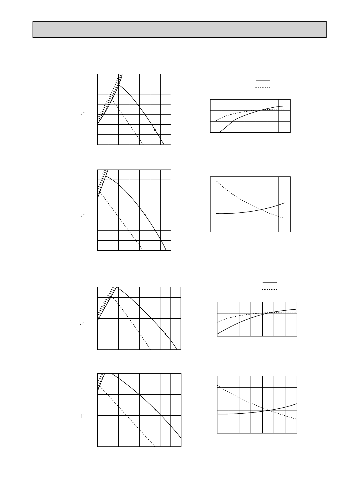
9-3. PEAD-RP·EA,EA2,GA
)
9-3-1. FAN PERFORMANCE AND CORRECTED AIR FLOW
PEAD-RP35EA2
PEAD-RP50EA
140
120
100
(1Pa 0.1mmAq)
External static pressure (Pa)
Fan Performance <30Pa>
80
60
40
20
6 8 10 12 14 16 18 20
Airflow (CMM)
Corrected Airflow
Cooling
1.1
1.0
0.9
0.8
Correction factor
810121416182022
Airflow (CMM)
Capacity
input
PEAD-RP60EA
160
140
120
100
Fan Performance <70Pa>
80
60
(1Pa 0.1mmAq)
40
External static pressure (Pa)
20
810121416182022
Airflow (CMM)
120
100
(1Pa 0.1mmAq)
External static pressure (Pa)
140
120
100
(1Pa 0.1mmAq)
External static pressure (Pa)
Fan Performance <30Pa>
80
60
40
20
81012141618202224
Airflow (CMM)
Fan Performance <70Pa>
80
60
40
20
10 12 14 16 18 20 22 24 26
Airflow (CMM
Heating
1.3
1.2
1.1
1.0
Correction factor
0.9
0.8
810121416182022
Airflow (CMM)
Corrected Airflow
Cooling
1.1
1.0
0.9
0.8
Correction factor
12 14 16 18 20 22 24 26
Airflow (CMM)
Heating
1.3
1.2
1.1
1.0
Correction factor
0.9
0.8
12 14 16 18 20 22 24 26
Airflow (CMM)
Capacity
input
41
Page 42

PEAD-RP71EA
Fan performance <130Pa>
Recommended range
200
180
160
140
120
100
80
=
60
40
(1Pa 0.1mmAq)
20
External static pressure (Pa)
12 16 20 24 28 32
Airflow
Corrected Airflow
1.1
1.0
0.9
Correction factor
0.8
12 16 20 24 28 32
PEAD-RP100EA2
PEAD-RP125EA
Lo
Cooling
Hi
(CMM)
Airflow (CMM)
Capacity
Input
Fan performance <70Pa>
Recommended range
180
160
140
120
100
80
=
60
40
(1Pa 0.1mmAq)
20
External static pressure (Pa)
12 16 20 24 28 32
Airflow
Heating
1.3
1.2
1.1
1.0
Correction factor
0.9
0.8
12 16 20 24 28 32
Lo
Hi
(CMM)
Airflow (CMM)
Fan performance <130Pa>
Recommended range
220
200
180
160
140
120
100
80
=
60
(1Pa 0.1mmAq)
40
20
External static pressure (Pa)
Lo
32 34 36 38 40 42 44 46 48
Airflow
(CMM)
Hi
Corrected Air Flow
Cooling
1.1
1.0
0.9
Correction factor
0.8
32 34 36 38 40 42 44 46 48
Airflow (CMM)
Capacity
Input
Fan performance <70Pa>
Recommended range
220
200
180
160
140
120
100
80
=
60
(1Pa 0.1mmAq)
40
20
External static pressure (Pa)
32 34 36 38 40 42 44 46
Airflow
Heating
1.2
1.1
1.0
0.9
Correction factor
0.8
32 34 36 38 40 42 44 46 48
Hi
Lo
(CMM)
Airflow (CMM)
42
Page 43

PEAD-RP60GA
PEAD-RP71GA
43
Page 44

PEAD-RP100GA
44
Page 45

10
NOISE CRITERION CURVES
10-1. INDOOR UNIT
PLA-RP35BA PLA-RP50BA
NOTCH SPL(dB) LINE
High 31
Medium1 29
Medium2 28
Low 27
OCTAVE BAND SOUND PRESSURE LEVEL, dB (0 dB = 0.0002 μbar)
90
80
70
60
50
40
30
APPROXIMATE
20
THRESHOLD OF
HEARING FOR
CONTINUOUS
NOISE
10
63 125 250 500 1000 2000 4000 8000
BAND CENTER FREQUENCIES, Hz
NC-70
NC-60
NC-50
NC-40
NC-30
NC-20
OCTAVE BAND SOUND PRESSURE LEVEL, dB (0 dB = 0.0002 μbar)
90
80
70
60
50
40
30
APPROXIMATE
20
THRESHOLD OF
HEARING FOR
CONTINUOUS
NOISE
10
63 125 250 500 1000 2000 4000 8000
NOTCH SPL(dB) LINE
High 32
Medium1 31
Medium2 29
Low 28
NC-70
NC-60
NC-50
NC-40
NC-30
NC-20
BAND CENTER FREQUENCIES, Hz
PLA-RP60BA
90
80
70
60
50
40
30
APPROXIMATE
20
OCTAVE BAND SOUND PRESSURE LEVEL, dB (0 dB = 0.0002 μbar)
THRESHOLD OF
HEARING FOR
CONTINUOUS
NOISE
10
63 125 250 500 1000 2000 4000 8000
NOTCH SPL(dB) LINE
High 32
Medium1 31
Medium2 29
Low 28
BAND CENTER FREQUENCIES, Hz
NC-70
NC-60
NC-50
NC-40
NC-30
NC-20
PLA-RP71BA2
90
80
70
60
50
40
30
APPROXIMATE
20
OCTAVE BAND SOUND PRESSURE LEVEL, dB (0 dB = 0.0002 μbar)
THRESHOLD OF
HEARING FOR
CONTINUOUS
NOISE
10
63 125 250 500 1000 2000 4000 8000
NOTCH SPL(dB) LINE
High 34
Medium1 32
Medium2 30
Low 28
NC-70
NC-60
NC-50
NC-40
NC-30
NC-20
BAND CENTER FREQUENCIES, Hz
45
Page 46

PLA-RP100BA
PLA-RP100BA2
NOTCH SPL(dB) LINE
High 40
Medium1 37
Medium2 34
Low 32
PLA-RP125BA
PLA-RP125BA2
NOTCH SPL(dB) LINE
High 41
Medium1 39
Medium2 36
Low 34
OCTAVE BAND SOUND PRESSURE LEVEL, dB (0 dB = 0.0002 μbar)
90
80
70
60
50
40
30
APPROXIMATE
20
THRESHOLD OF
HEARING FOR
CONTINUOUS
NOISE
10
63 125 250 500 1000 2000 4000 8000
BAND CENTER FREQUENCIES, Hz
NC-70
NC-60
NC-50
NC-40
NC-30
NC-20
OCTAVE BAND SOUND PRESSURE LEVEL, dB (0 dB = 0.0002 μbar)
90
80
70
60
50
40
30
APPROXIMATE
20
THRESHOLD OF
HEARING FOR
CONTINUOUS
NOISE
10
63 125 250 500 1000 2000 4000 8000
BAND CENTER FREQUENCIES, Hz
NC-70
NC-60
NC-50
NC-40
NC-30
NC-20
CEILING
UNIT
1.5m
MICROPHONE
46
Page 47

PEAD-RP35EA2
PEAD-RP50EA
70
60
50
40
30
20
10
Approximate minimum
audible limit on
continuous noise
OCTAVE BAND PRESSURE LEVEL (dB) 0dB = 20MPa
0
63 125 250 500 1000 2000 4000 8000
OCTAVE BAND CENTER FREQUENCIES (Hz)
(External static
pressure 30Pa)
High
Low
NC60
NC50
NC40
NC30
NC20
PEAD-RP35EA2
PEAD-RP50EA
70
60
50
40
30
20
10
Approximate minimum
audible limit on
continuous noise
OCTAVE BAND PRESSURE LEVEL (dB) 0dB = 20MPa
0
63 125 250 500 1000 2000 4000 8000
OCTAVE BAND CENTER FREQUENCIES (Hz)
(External static
pressure 70Pa)
High
Low
NC60
NC50
NC40
NC30
NC20
PEAD-RP60EA
70
60
50
40
30
20
10
Approximate minimum
audible limit on
continuous noise
OCTAVE BAND PRESSURE LEVEL (dB) 0dB = 20MPa
0
63 125 250 500 1000 2000 4000 8000
OCTAVE BAND CENTER FREQUENCIES (Hz)
(External static
pressure 30Pa)
High
Low
NC60
NC50
NC40
NC30
NC20
PEAD-RP60EA
70
60
50
40
30
20
10
Approximate minimum
audible limit on
continuous noise
OCTAVE BAND PRESSURE LEVEL (dB) 0dB = 20MPa
0
63 125 250 500 1000 2000 4000 8000
OCTAVE BAND CENTER FREQUENCIES (Hz)
(External static
pressure 70Pa)
High
Low
NC60
NC50
NC40
NC30
NC20
47
Page 48

48
Page 49

PKA-RP35GAL
PKA-RP50GAL
NOTCH
High
Medium1
Medium2
Low
SPL(dB)
43
41
38
36
LINE
PKA-RP50FAL2
PKA-RP60FAL
NOTCH
High
Low
SPL(dB)39LINE
45
OCTAVE BAND SOUND PRESSURE LEVEL, dB (0 dB = 0.0002 μbar)
90
80
70
60
50
40
30
APPROXIMATE
20
TERESHOLD OF
HEARING FOR
CONTINUOUS
NOISE
10
63 125 250 500 1000 2000 4000 8000
BAND CENTER FREQUENCIES, Hz
NC-70
NC-60
NC-50
NC-40
NC-30
NC-20
OCTAVE BAND SOUND PRESSURE LEVEL, dB(0 dB = 0.0002 μbar)
90
80
70
60
50
40
30
APPROXIMATE
20
TERESHOLD OF
HEARING FOR
CONTINUOUS
NOISE
10
63 125 250 500 1000 2000 4000 8000
BAND CENTER FREQUENCIES, Hz
NC-70
NC-60
NC-50
NC-40
NC-30
NC-20
UNIT
1m
1m
MICROPHONE
WALL
PKA-RP100FAL
90
80
70
60
50
40
30
APPROXIMATE
20
TERESHOLD OF
OCTAVE BAND SOUND PRESSURE LEVEL, dB(0 dB = 0.0002 μbar)
HEARING FOR
CONTINUOUS
NOISE
10
63 125 250 500 1000 2000 4000 8000
NOTCH
High
Low
BAND CENTER FREQUENCIES, Hz
SPL(dB)
46
41
LINE
NC-70
NC-60
NC-50
NC-40
NC-30
NC-20
49
Page 50

10-2. OUTDOOR UNIT
PUHZ-HRP71VHA
PUHZ-HRP100VHA
PUHZ-HRP100YHA
PUHZ-HRP125YHA
90
MODE
COOLING
HEATING
SPL(dB)
52
53
LINE
PUHZ-HRP71VHA2
PUHZ-HRP100VHA2
PUHZ-HRP100YHA2
PUHZ-HRP125YHA2
90
MODE
COOLING
HEATING
SPL(dB)
51
52
LINE
80
70
60
50
40
30
APPROXIMATE
20
THRESHOLD OF
HEARING FOR
CONTINUOUS
OCTAVE BAND SOUND PRESSURE LEVEL, dB (0 dB = 0.0002 μbar)
NOISE
10
63 125 250 500 1000 2000 4000 8000
MICROPHONE
BAND CENTER FREQUENCIES, Hz
1m
NC-70
NC-60
NC-50
NC-40
NC-30
NC-20
UNIT
OCTAVE BAND SOUND PRESSURE LEVEL, dB (0 dB = 0.0002 μbar)
80
70
60
50
40
30
APPROXIMATE
20
THRESHOLD OF
HEARING FOR
CONTINUOUS
NOISE
10
63 125 250 500 1000 2000 4000 8000
BAND CENTER FREQUENCIES, Hz
NC-70
NC-60
NC-50
NC-40
NC-30
NC-20
1.5m
GROUND
50
Page 51

11
OPTIONAL PARTS
11-1. INDOOR UNIT
Part Name Model Name Applicable model
Remote sensor PAC-SE41TS-E
Remote operation adapter
Multiple remote controller adapter
Remote on/off adapter PAC-SE55RA-E
Power supply terminal kit L/N/Earth PAC-SG96HR-E
L/N PAC-SG97HR-E
Decoration panel
Decoration panel with Wireless remote controller
Decoration panel with Wired remote controller
Automatic filter elevation panel
i-see sensor corner panel
Wireless signal receiver
Space panel
Air outlet shutter plate
Multi-function casement
Flange for fresh air intake
High-efficiency filter element (PAC-SH53TM-E is needed.)
Wired remote controller kit PAR-21MAAT-E PKA-RP•GAL
(with terminal bed) PKA-RP•FAL(2)
Drain lift up mechanism PAC-SE90DM-E PKA-RP•FAL(2)
Motor
(for high external static pressure) PEAD-RP100EA2
Drain lift up mechanism PAC-KE03DM-F PEAD-RP•EA,EA2
Insulation kit PAC-SK010DK PEAD-RP•GA
PAC-SF40RM-E
PAC-SA88HA-E (1 pc.)
PAC-725AD (10 pcs.)
PAC-SH52HR-E
PLP-6BA
PLP-6BALM
PLP-6BAMD
PLP-6BAJ
PAC-SA1ME-E
PAR-SA9FA-E
PAC-SH48AS-E
PAC-SH51SP-E
PAC-SH53TM-E
PAC-SH65OF-E
PAC-SH59KF-E
PAC-SK003MT-F PEAD-RP125EA
All models
PEAD-RP•EA(2)
PKA-RP•GAL/FAL(2)
PLA-RP•BA(2)
PEAD-RP•GA
PLA-RP•BA(2)
11-2. OUTDOOR UNIT
Part Name Model Name
M-NET adapter PAC-SF80MA-E PUHZ-HRP71-125
A-control service tool PAC-SK52ST
Drain socket PAC-SG61DS-E
Air outlet guide (HRP71/100/125 needs 2 pieces) PAC-SG59SG-E
Air protect guide (HRP71/100/125 needs 2 pieces) PAC-SG57AG-E
Drain pan PAC-SG64DP-E
Filter dryer
Distribution pipe
Joint pipe
Interface (cased) PAC-IF011B-E
(Unit Extension pipe)
(:9.52)
(Twin)
(:15.88 :19.05)
PAC-SG82DR-E
MSDD-50SR-E
PAC-SG75RJ-E
Applicable model
PUHZ-HRP71-125
PUHZ-HRP71-125
PUHZ-HRP71-125
PUHZ-HRP71-125
PUHZ-HRP71-125
PUHZ-HRP71-125
PUHZ-HRP71-125
PUHZ-HRP71-125
PUHZ-HRP71-125
51
Page 52

HEAD OFFICE : TOKYO BLDG., 2-7-3, MARUNOUCHI, CHIYODA-KU, TOKYO 100-8310, JAPAN
Copyright 2007 MITSUBISHI ELECTRIC ENGINEERING CO., LTD.
Distributed in Sep. 2008 No.OCS11 REVISED EDITION-A PDF 6
Distributed in Oct. 2007 No.OCS11 PDF 7
Made in Japan
New publication, effective Sep. 2008
Specifications subject to change without notice.
 Loading...