

Mitsubishi Electric MXZ-3C24NA, MXZ-4C36NA, MXZ-5C42NA, MXZ-3C24NAHZ, MXZ-3C30NAHZ Service Manual
...
HFC
utilized
R410A
TM
INDOOR UNIT
OUTDOOR UNIT
SERVICE MANUAL
Models
MXZ-3C24NA
Revision A:
• MXZ-3C24NA, MXZ-3C30NA and MXZ4C36NA have been added.
Please void OBH702.
No. OBH702
REVISED EDITION-A
MXZ-3C30NA
MXZ-4C36NA
MXZ-5C42NA
MXZ-2C20NAHZ
MXZ-3C24NAHZ
MXZ-3C30NAHZ
Indoor unit service manual
MSZ-FE·NA Series (OBH542)
MSZ-GE·NA Series (OBH548)
MFZ-KA·NA Series (OBH568)
SEZ-KD·NA Series
PLA-A·BA Series (OCH420)
PCA-A·KA Series (OCH455)
PEAD-A·AA Series
SLZ-KA·NA Series (OCH487)
MSZ-FH·NA Series (OBH683)
MVZ-A·AA Series
CONTENTS
1. TECHNICAL CHANGES ··································· 2
2. PART NAMES AND FUNCTIONS ····················· 3
3. SPECIFICATION ················································ 4
4. NOISE CRITERIA CURVES ·····························11
5. OUTLINES AND DIMENSIONS ······················ 13
6. WIRING DIAGRAM ·········································· 18
7. REFRIGERANT SYSTEM DIAGRAM ············· 23
8. DATA ································································ 34
9. ACTUATOR CONTROL ··································· 56
10. SERVICE FUNCTIONS ···································· 57
11. TROUBLESHOOTING ····································· 59
12. DISASSEMBLY INSTRUCTIONS ···················· 77
MXZ-3C24NA
MXZ-3C30NA
MXZ-4C36NA
INDOOR UNITS COMBINATION TABLES
PARTS CATALOG (OBB702)
Revision A:
OBH702A
• MXZ-3C24NA, MXZ-3C30NA and MXZ-4C36NA have been added.
Use the specifi ed refrigerant only
Never use any refrigerant other than that specified.
Doing so may cause a burst, an explosion, or fire when the unit is being used, serviced, or disposed of.
Correct refrigerant is specified in the manuals and on the spec labels provided with our products.
We will not be held responsible for mechanical failure, system malfunction, unit breakdown or accidents caused by
failure to follow the instructions.
1
TECHNICAL CHANGES
MXZ-5C42NA
MXZ-2C20NAHZ
MXZ-3C24NAHZ
MXZ-3C30NAHZ
1. New model
MXZ-3C24NA
MXZ-3C30NA
MXZ-4C36NA
1. New model
2
2
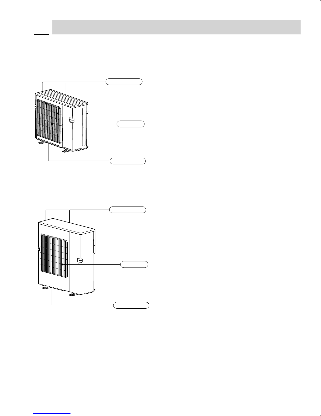
Air outlet
Drain outlet
Air inlet
(Back and side)
OBH702A
PART NAMES AND FUNCTIONS
MXZ-3C24NA
MXZ-3C30NA
MXZ-4C36NA
MXZ-5C42NA
MXZ-2C20NAHZ
MXZ-3C24NAHZ
MXZ-3C30NAHZ
Air inlet
(Back and side)
Air outlet
Drain outlet
3
Cooling
Heating
Mode
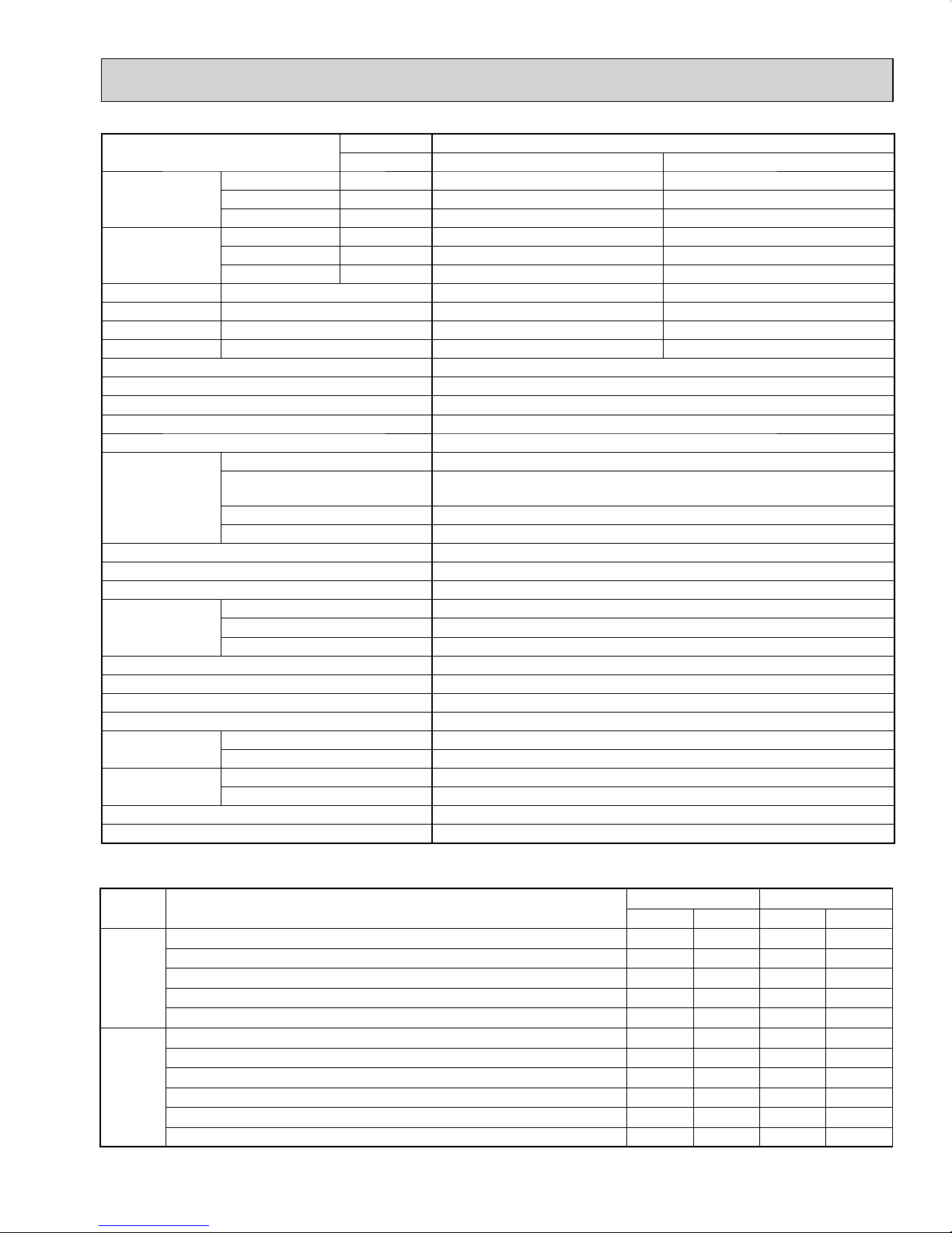
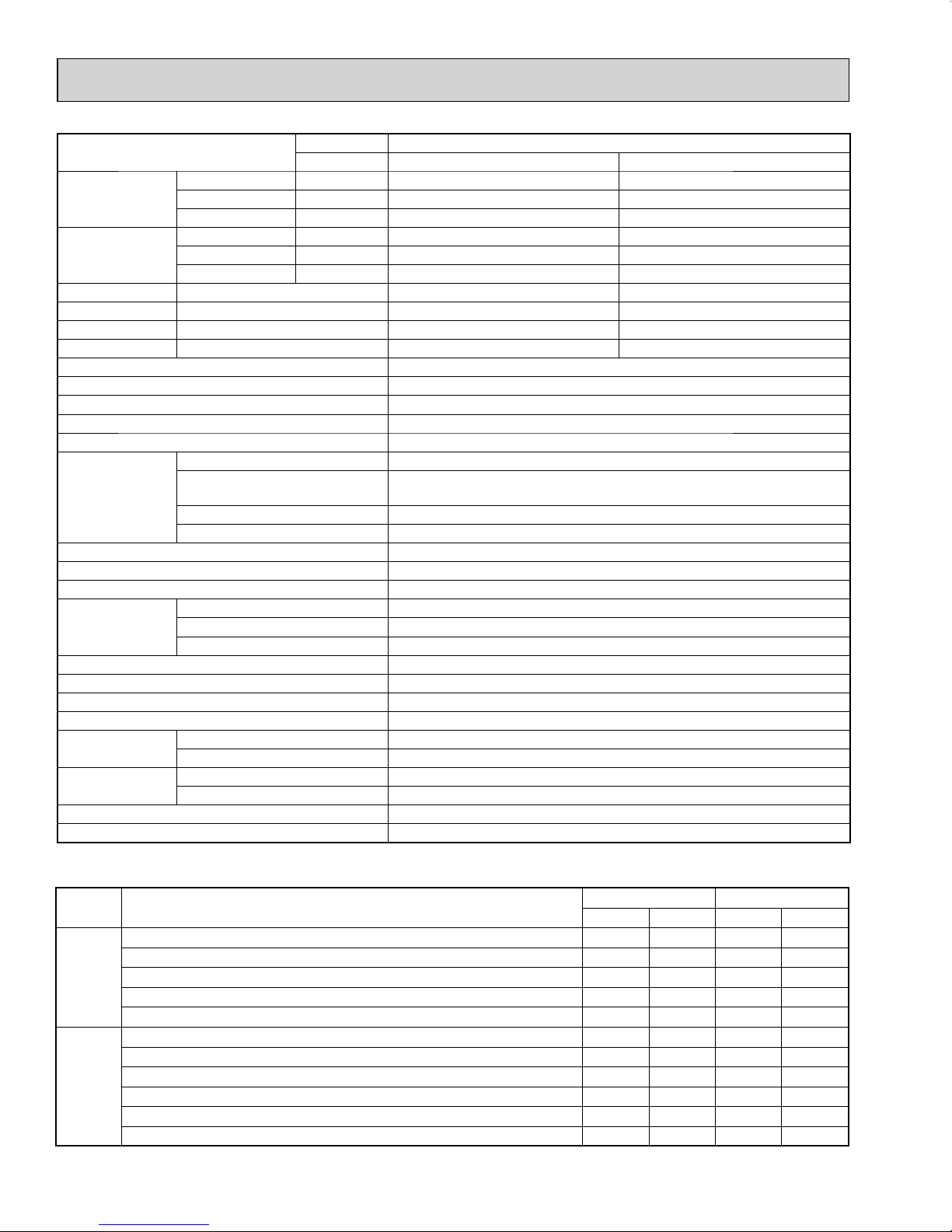
*1: "A" Cooling steady state at rated compressor speed
"B-2" Cooling steady state at rated compressor speed
"B-1" Cooling steady state at minimum compressor speed
Low ambient cooling steady state at minimum compressor speed
Intermediate cooling steady state at intermediate compressor speed
*1: Standard rating-heating at rated compressor speed
*2: Low temperature heating at maximum compressor speed
Maximum temperature heating at minimum compressor speed
High temperature heating at minimum compressor speed
Frost accumulation at rated compressor speed
Frost accumulation at intermediate compressor speed
Test
Indoor air condition Outdoor air condition
Dry bulb
Wet bulb
Dry bulb
Wet bulb
80
80
80
80
80
70
70
70
70
70
70
67
67
67
67
67
60
60
60
60
60
60
95
82
82
67
87
47
17
62
47
35
35
(75)
(65)
(65)
(53.5)
(69)
43
15
56.5
43
33
33
Unit: °F
3
OBH702A
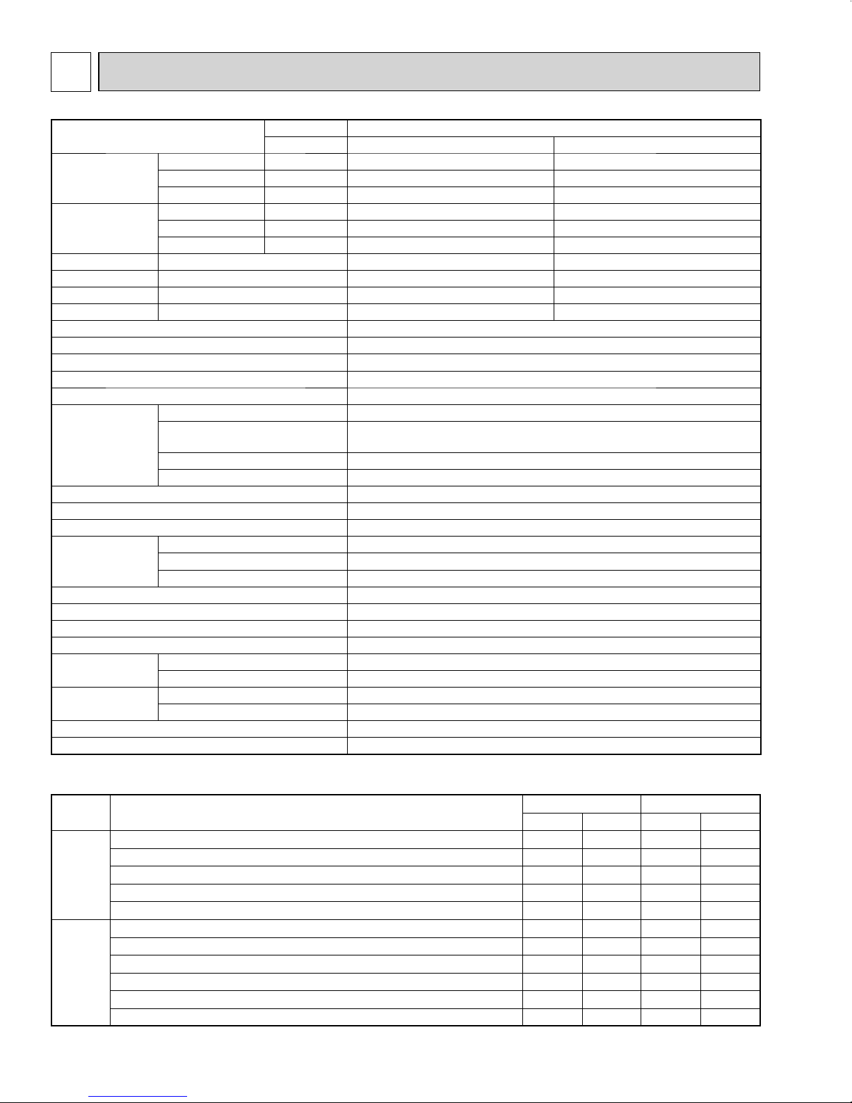
SPECIFICATION
Item
Cooling *1 Btu/h
Capacity
Power
consumption
EER Cooling
SEER Cooling
HSPF IV(V) Heating
COP Heating
External fi nish
Power supply V, phase, Hz
Max. fuse size (time delay) A
Min. circuit ampacity A
Fan motor F.L.A
Compressor
Refrigerant control
Sound level dB(A)
Defrost method
Dimensions
Weight lb.
Remote controller
Control voltage (by built-in transformer)
Refrigerant piping
Valve size
Connection method
Refrigerant charge (R410A) lb.
Refrigeration oil (Model) oz.
NOTE : Test conditions are based on ARI 210/240.
Heating 47 *1 Btu/h
Heating 17 *2 Btu/h
Cooling *1 W
Heating 47 *1 W
Heating 17 *2 W
Model
Winding resistance
(at 68 ºF)
W in.
D in.
H in.
Liquid in.
Gas in.
Indoor
Outdoor
Outdoor model
Indoor type
R.L.A
L.R.A
MXZ-3C24NA
Non-Duct (06+09+09 ) Duct ( 09+09+09)
22,000 23,600
25,000 24,600
19,600 19,600
1,620 2,100
1,750 1,900
2,120 2,230
13.6 11.2
20.0 16.0
9.8 9.2
4.20 3.80
Munsell 3.0Y 7.8/1.1
208/230, 1, 60
25
22.1
1.9
SNB220FQGMC
Ω
U-V 0.95 V-W 0.95 W-U 0.95
12
13.7
LEV
51/55
Reverse cycle
37-13/32
13
31-11/32
135
Wireless type
4
Not supplied (optional parts)
1/4
A:1/2 B,C:3/8
Flared
Flared
6lb. 13oz.
24.7 (FV50S)
4
Cooling
Heating
Mode
*1: "A" Cooling steady state at rated compressor speed
"B-2" Cooling steady state at rated compressor speed
"B-1" Cooling steady state at minimum compressor speed
Low ambient cooling steady state at minimum compressor speed
Intermediate cooling steady state at intermediate compressor speed
*1: Standard rating-heating at rated compressor speed
*2: Low temperature heating at maximum compressor speed
Maximum temperature heating at minimum compressor speed
High temperature heating at minimum compressor speed
Frost accumulation at rated compressor speed
Frost accumulation at intermediate compressor speed
Test
Indoor air condition Outdoor air condition
Dry bulb
Wet bulb
Dry bulb
Wet bulb
80
80
80
80
80
70
70
70
70
70
70
67
67
67
67
67
60
60
60
60
60
60
95
82
82
67
87
47
17
62
47
35
35
(75)
(65)
(65)
(53.5)
(69)
43
15
56.5
43
33
33
Unit: °F
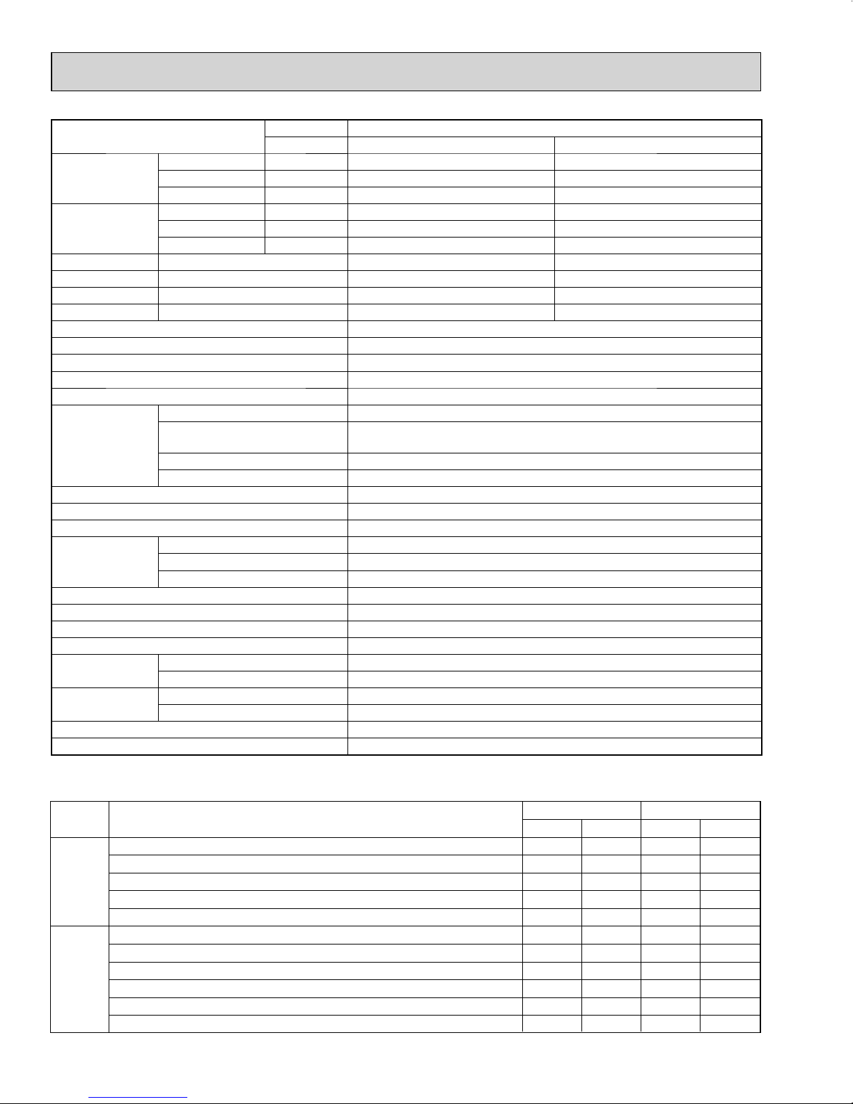
Item
OBH702A
Cooling *1 Btu/h
Capacity
Power
consumption
EER Cooling
SEER Cooling
HSPF IV(V) Heating
COP Heating
External fi nish
Power supply V, phase, Hz
Max. fuse size (time delay) A
Min. circuit ampacity A
Fan motor F.L.A
Compressor
Refrigerant control
Sound level dB(A)
Defrost method
Dimensions
Weight lb.
Remote controller
Control voltage (by built-in transformer)
Refrigerant piping
Valve size
Connection method
Refrigerant charge (R410A) lb.
Refrigeration oil (Model) oz.
NOTE : Test conditions are based on ARI 210/240.
Heating 47 *1 Btu/h
Heating 17 *2 Btu/h
Cooling *1 W
Heating 47 *1 W
Heating 17 *2 W
Model
Winding resistance
(at 68 ºF)
W in.
D in.
H in.
Liquid in.
Gas in.
Indoor
Outdoor
Outdoor model
Indoor type
R.L.A
L.R.A
MXZ-3C30NA
Non-Duct (09+09+12 ) Duct ( 09+09+12)
28,400 27,400
28,600 27,600
21,000 21,000
2,680 2,860
2,150 2,220
2,120 2,140
10.6 9.6
19.0 16.2
10.6 10.6
3.90 3.64
Munsell 3.0Y 7.8/1.1
208/230, 1, 60
25
22.1
1.9
SNB220FQGMC
Ω
U-V 0.95 V-W 0.95 W-U 0.95
12
13.7
LEV
52/56
Reverse cycle
37-13/32
13
31-11/32
135
Wireless type
4
Not supplied (optional parts)
1/4
A:1/2 B,C:3/8
Flared
Flared
6lb. 13oz.
24.7 (FV50S)
5
Cooling
Heating
Mode
*1: "A" Cooling steady state at rated compressor speed
"B-2" Cooling steady state at rated compressor speed
"B-1" Cooling steady state at minimum compressor speed
Low ambient cooling steady state at minimum compressor speed
Intermediate cooling steady state at intermediate compressor speed
*1: Standard rating-heating at rated compressor speed
*2: Low temperature heating at maximum compressor speed
Maximum temperature heating at minimum compressor speed
High temperature heating at minimum compressor speed
Frost accumulation at rated compressor speed
Frost accumulation at intermediate compressor speed
Test
Indoor air condition Outdoor air condition
Dry bulb
Wet bulb
Dry bulb
Wet bulb
80
80
80
80
80
70
70
70
70
70
70
67
67
67
67
67
60
60
60
60
60
60
95
82
82
67
87
47
17
62
47
35
35
(75)
(65)
(65)
(53.5)
(69)
43
15
56.5
43
33
33
Unit: °F
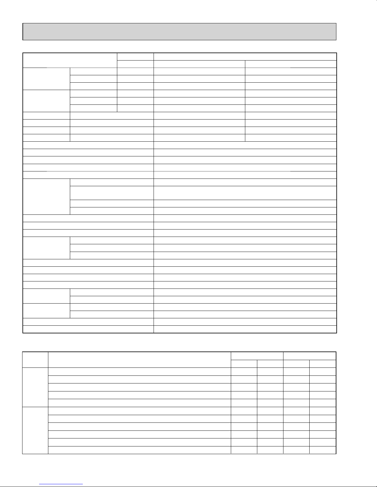
Item
OBH702A
Cooling *1 Btu/h
Capacity
Power
consumption
EER Cooling
SEER Cooling
HSPF IV(V) Heating
COP Heating
External fi nish
Power supply V, phase, Hz
Max. fuse size (time delay) A
Min. circuit ampacity A
Fan motor F.L.A
Compressor
Refrigerant control
Sound level dB(A)
Defrost method
Dimensions
Weight lb.
Remote controller
Control voltage (by built-in transformer)
Refrigerant piping
Valve size
Connection method
Refrigerant charge (R410A) lb.
Refrigeration oil (Model) oz.
NOTE : Test conditions are based on ARI 210/240.
Heating 47 *1 Btu/h
Heating 17 *2 Btu/h
Cooling *1 W
Heating 47 *1 W
Heating 17 *2 W
Model
Winding resistance
(at 68 ºF)
W in.
D in.
H in.
Liquid in.
Gas in.
Indoor
Outdoor
Outdoor model
Indoor type
R.L.A
L.R.A
MXZ-4C36NA
Non-Duct (09+09+09+09 ) Duct ( 09+09+09+09)
35,400 34,400
36,000 34,400
26,600 26,600
3,760 3,940
3,020 3,100
3,340 3,450
9.4 8.7
19.2 16.0
11.0 9.8
3.50 3.25
Munsell 3.0Y 7.8/1.1
208/230, 1, 60
25
22.1
1.9
SNB220FQGMC
Ω
U-V 0.95 V-W 0.95 W-U 0.95
12
13.7
LEV
54/56
Reverse cycle
37-13/32
13
31-11/32
137
Wireless type
4
Not supplied (optional parts)
1/4
A:1/2 B,C,D:3/8
Flared
Flared
6lb. 13oz.
24.7 (FV50S)
6

Cooling
Heating
Mode
*1: "A" Cooling steady state at rated compressor speed
"B-2" Cooling steady state at rated compressor speed
"B-1" Cooling steady state at minimum compressor speed
Low ambient cooling steady state at minimum compressor speed
Intermediate cooling steady state at intermediate compressor speed
*1: Standard rating-heating at rated compressor speed
*2: Low temperature heating at maximum compressor speed
Maximum temperature heating at minimum compressor speed
High temperature heating at minimum compressor speed
Frost accumulation at rated compressor speed
Frost accumulation at intermediate compressor speed
Test
Indoor air condition Outdoor air condition
Dry bulb
Wet bulb
Dry bulb
Wet bulb
80
80
80
80
80
70
70
70
70
70
70
67
67
67
67
67
60
60
60
60
60
60
95
82
82
67
87
47
17
62
47
35
35
(75)
(65)
(65)
(53.5)
(69)
43
15
56.5
43
33
33
Unit: °F
Item
OBH702A
Cooling *1 Btu/h
Capacity
Power
consumption
EER Cooling
SEER Cooling
HSPF IV(V) Heating
COP Heating
External fi nish
Power supply V, phase, Hz
Max. fuse size (time delay) A
Min. circuit ampacity A
Fan motor F.L.A
Compressor
Refrigerant control
Sound level dB(A)
Defrost method
Dimensions
Weight lb.
Remote controller
Control voltage (by built-in transformer)
Refrigerant piping
Valve size
Connection method
Refrigerant charge (R410A) lb.
Refrigeration oil (Model) oz.
NOTE : Test conditions are based on ARI 210/240.
Heating 47 *1 Btu/h
Heating 17 *2 Btu/h
Cooling *1 W
Heating 47 *1 W
Heating 17 *2 W
Model
Winding resistance
(at 68 ºF)
W in.
D in.
H in.
Liquid in.
Gas in.
Indoor
Outdoor
Outdoor model
Indoor type
R.L.A
L.R.A
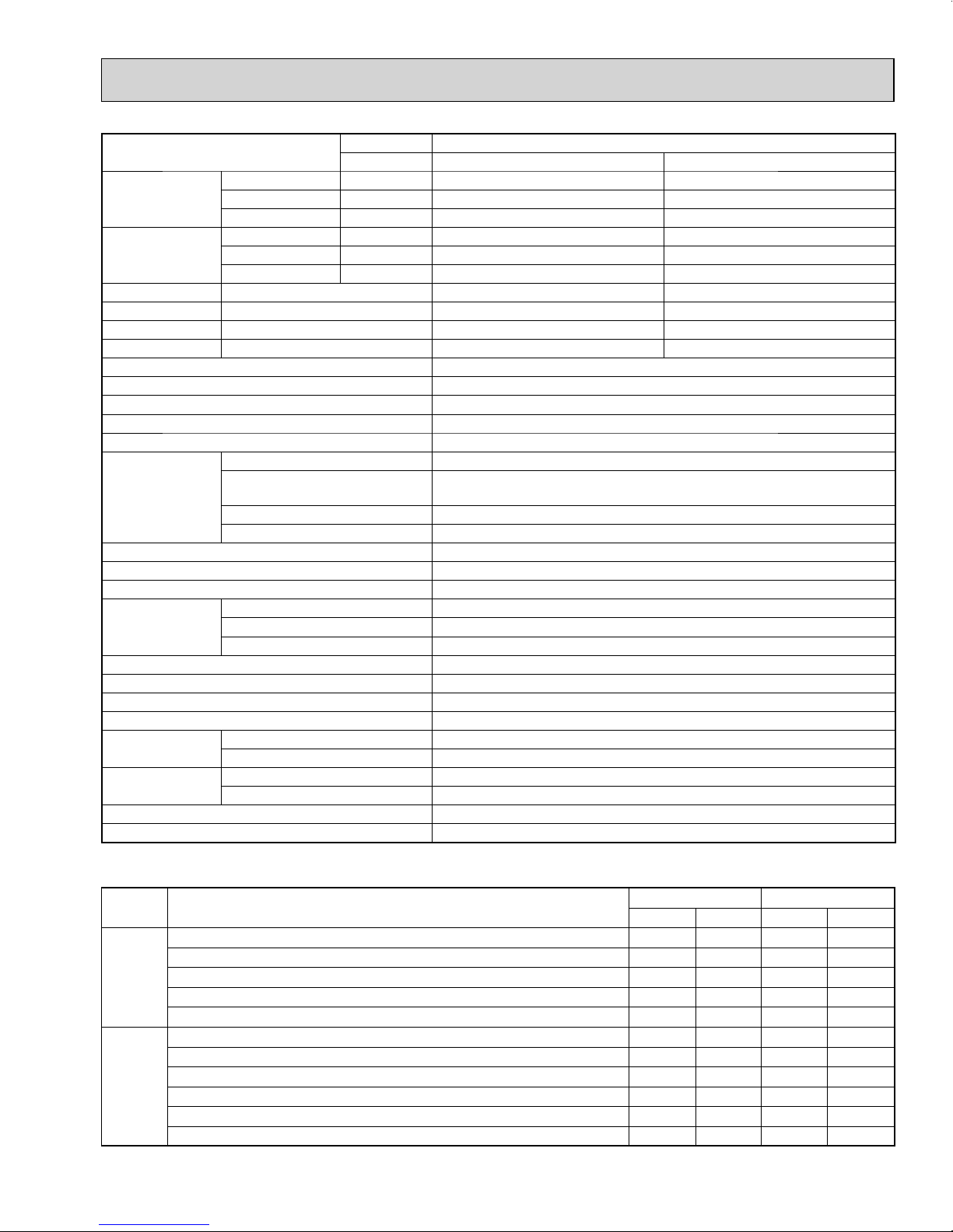
MXZ-5C42NA
Non-Duct (06+09+09+09+09) Duct (09+09+09+09+09)
40,500 37,500
45,000 41,000
24,400 23,000
4,403 4,112
3,575 3,463
2,943 2,869
9.2 9.0
19.7 15.2
10.3 9.1
3.69 3.47
Munsell 3.0Y 7.8/1.1
208/230, 1, 60
40
31.9
1.9
MNB33FBTMC-L
Ω
U-V 0.30 V-W 0.30 W-U 0.30
20
28.8
LEV
56/58
Reverse cycle
37-13/32
13
41-17/64
189
Wireless type
4
Not supplied (optional parts)
1/4
A:1/2 B,C,D,E: 3/8
Flared
Flared
8 lb. 13 oz.
37.4 (FV50S)
7
Cooling
Heating
Mode
*1: "A" Cooling steady state at rated compressor speed
"B-2" Cooling steady state at rated compressor speed
"B-1" Cooling steady state at minimum compressor speed
Low ambient cooling steady state at minimum compressor speed
Intermediate cooling steady state at intermediate compressor speed
*1: Standard rating-heating at rated compressor speed
*2: Low temperature heating at maximum compressor speed
Maximum temperature heating at minimum compressor speed
High temperature heating at minimum compressor speed
Frost accumulation at rated compressor speed
Frost accumulation at intermediate compressor speed
Test
Indoor air condition Outdoor air condition
Dry bulb
Wet bulb
Dry bulb
Wet bulb
80
80
80
80
80
70
70
70
70
70
70
67
67
67
67
67
60
60
60
60
60
60
95
82
82
67
87
47
17
62
47
35
35
(75)
(65)
(65)
(53.5)
(69)
43
15
56.5
43
33
33
Unit: °F
Item
OBH702A
Cooling *1 Btu/h
Capacity
Power
consumption
EER Cooling
SEER Cooling
HSPF IV(V) Heating
COP Heating
External fi nish
Power supply V, phase, Hz
Max. fuse size (time delay) A
Min. circuit ampacity A
Fan motor F.L.A
Compressor
Refrigerant control
Sound level dB(A)
Defrost method
Dimensions
Weight lb.
Remote controller
Control voltage (by built-in transformer)
Refrigerant piping
Valve size
Connection method
Refrigerant charge (R410A) lb.
Refrigeration oil (Model) oz.
NOTE : Test conditions are based on ARI 210/240.
Heating 47 *1 Btu/h
Heating 17 *2 Btu/h
Cooling *1 W
Heating 47 *1 W
Heating 17 *2 W
Model
Winding resistance
(at 68 ºF)
W in.
D in.
H in.
Liquid in.
Gas in.
Indoor
Outdoor
Outdoor model
Indoor type
R.L.A
L.R.A
MXZ-2C20NAHZ
Non-Duct (09+09) Duct (09+12)
18,000 20,000
22,000 22,000
13,700 13,700
1,334 1,819
1,612 1,748
1,450 1,588
13.5 11.0
17.0 15.0
9.8 9.5
4.00 3.69
Munsell 3.0Y 7.8/1.1
208/230, 1, 60
40
28.9
1.9
MNB33FBTMC-L
Ω
U-V 0.30 V-W 0.30 W-U 0.30
20
28.8
LEV
54/58
Reverse cycle
37-13/32
13
41-17/64
187
Wireless type
4
Not supplied (optional parts)
1/4
A,B: 3/8
Flared
Flared
8 lb. 13 oz.
37.4 (FV50S)
8
Cooling
Heating
Mode
*1: "A" Cooling steady state at rated compressor speed
"B-2" Cooling steady state at rated compressor speed
"B-1" Cooling steady state at minimum compressor speed
Low ambient cooling steady state at minimum compressor speed
Intermediate cooling steady state at intermediate compressor speed
*1: Standard rating-heating at rated compressor speed
*2: Low temperature heating at maximum compressor speed
Maximum temperature heating at minimum compressor speed
High temperature heating at minimum compressor speed
Frost accumulation at rated compressor speed
Frost accumulation at intermediate compressor speed
Test
Indoor air condition Outdoor air condition
Dry bulb
Wet bulb
Dry bulb
Wet bulb
80
80
80
80
80
70
70
70
70
70
70
67
67
67
67
67
60
60
60
60
60
60
95
82
82
67
87
47
17
62
47
35
35
(75)
(65)
(65)
(53.5)
(69)
43
15
56.5
43
33
33
Unit: °F
Item
OBH702A
Cooling *1 Btu/h
Capacity
Power
consumption
EER Cooling
SEER Cooling
HSPF IV(V) Heating
COP Heating
External fi nish
Power supply V, phase, Hz
Max. fuse size (time delay) A
Min. circuit ampacity A
Fan motor F.L.A
Compressor
Refrigerant control
Sound level dB(A)
Defrost method
Dimensions
Weight lb.
Remote controller
Control voltage (by built-in transformer)
Refrigerant piping
Valve size
Connection method
Refrigerant charge (R410A) lb.
Refrigeration oil (Model) oz.
NOTE : Test conditions are based on ARI 210/240.
Heating 47 *1 Btu/h
Heating 17 *2 Btu/h
Cooling *1 W
Heating 47 *1 W
Heating 17 *2 W
Model
Winding resistance
(at 68 ºF)
W in.
D in.
H in.
Liquid in.
Gas in.
Indoor
Outdoor
Outdoor model
Indoor type
R.L.A
L.R.A
MXZ-3C24NAHZ
Non-Duct (06+06+09) Duct (09+09+09)
22,000 23,600
25,000 24,600
14,000 14,000
1,630 2,360
1,725 1,871
1,622 1,635
13.5 10.0
19.0 15.5
10.0 9.0
4.25 3.80
Munsell 3.0Y 7.8/1.1
208/230, 1, 60
40
29.9
1.9
MNB33FBTMC-L
Ω
U-V 0.30 V-W 0.30 W-U 0.30
20
28.8
LEV
54/58
Reverse cycle
37-13/32
13
41-17/64
189
Wireless type
4
Not supplied (optional parts)
1/4
A: 1/2 B,C: 3/8
Flared
Flared
8 lb. 13 oz.
37.4 (FV50S)
9
Cooling
Heating
Mode
*1: "A" Cooling steady state at rated compressor speed
"B-2" Cooling steady state at rated compressor speed
"B-1" Cooling steady state at minimum compressor speed
Low ambient cooling steady state at minimum compressor speed
Intermediate cooling steady state at intermediate compressor speed
*1: Standard rating-heating at rated compressor speed
*2: Low temperature heating at maximum compressor speed
Maximum temperature heating at minimum compressor speed
High temperature heating at minimum compressor speed
Frost accumulation at rated compressor speed
Frost accumulation at intermediate compressor speed
Test
Indoor air condition Outdoor air condition
Dry bulb
Wet bulb
Dry bulb
Wet bulb
80
80
80
80
80
70
70
70
70
70
70
67
67
67
67
67
60
60
60
60
60
60
95
82
82
67
87
47
17
62
47
35
35
(75)
(65)
(65)
(53.5)
(69)
43
15
56.5
43
33
33
Unit: °F
Item
OBH702A
Cooling *1 Btu/h
Capacity
Power
consumption
EER Cooling
SEER Cooling
HSPF IV(V) Heating
COP Heating
External fi nish
Power supply V, phase, Hz
Max. fuse size (time delay) A
Min. circuit ampacity A
Fan motor F.L.A
Compressor
Refrigerant control
Sound level dB(A)
Defrost method
Dimensions
Weight lb.
Remote controller
Control voltage (by built-in transformer)
Refrigerant piping
Valve size
Connection method
Refrigerant charge (R410A) lb.
Refrigeration oil (Model) oz.
NOTE : Test conditions are based on ARI 210/240.
Heating 47 *1 Btu/h
Heating 17 *2 Btu/h
Cooling *1 W
Heating 47 *1 W
Heating 17 *2 W
Model
Winding resistance
(at 68 ºF)
W in.
D in.
H in.
Liquid in.
Gas in.
Indoor
Outdoor
Outdoor model
Indoor type
R.L.A
L.R.A
MXZ-3C30NAHZ
Non-Duct (09+09+12) Duct (09+09+12)
28,400 27,400
28,600 27,600
18,000 17,000
2,272 2,661
2,096 2,187
1,991 1,993
12.5 10.3
18.0 16.0
11.0 9.8
4.00 3.70
Munsell 3.0Y 7.8/1.1
208/230, 1, 60
40
29.9
1.9
MNB33FBTMC-L
Ω
U-V 0.30 V-W 0.30 W-U 0.30
20
28.8
LEV
54/58
Reverse cycle
37-13/32
13
41-17/64
189
Wireless type
4
Not supplied (optional parts)
1/4
A: 1/2 B,C: 3/8
Flared
Flared
8 lb. 13 oz.
37.4 (FV50S)
10
CoolingHigh
FUNCTION
FAN SPEED
HeatingHigh
54
SPL(dB(A))56LINE
90
80
70
60
50
40
30
20
10
63 125 250 500 1000 2000 4000 8000
APPROXIMATE
THRESHOLD OF
HEARING FOR
CONTINUOUS
NOISE
NC-60
NC-50
NC-40
NC-30
NC-20
NC-70
OCTAVE BAND SOUND PRESSURE LEVEL, 0dB = 0.0002 MICRO BAR
BAND CENTER FREQUENCIES, Hz
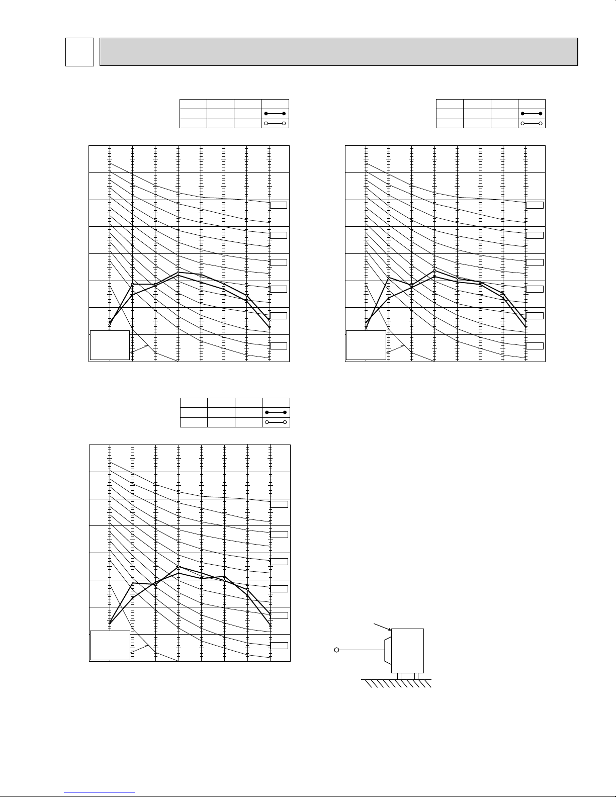
CoolingHigh
FUNCTION
FAN SPEED
HeatingHigh
51
SPL(dB(A))55LINE
90
80
70
60
50
40
30
20
10
63 125 250 500 1000 2000 4000 8000
APPROXIMATE
THRESHOLD OF
HEARING FOR
CONTINUOUS
NOISE
NC-60
NC-50
NC-40
NC-30
NC-20
NC-70
OCTAVE BAND SOUND PRESSURE LEVEL, 0dB = 0.0002 MICRO BAR
BAND CENTER FREQUENCIES, Hz
4
OBH702A
NOISE CRITERIA CURVES
MXZ-3C24NA
MXZ-4C36NA
MXZ-3C30NA
FAN SPEED
90
80
70
60
50
40
30
OCTAVE BAND SOUND PRESSURE LEVEL, 0dB = 0.0002 MICRO BAR
20
APPROXIMATE
THRESHOLD OF
HEARING FOR
CONTINUOUS
NOISE
10
63 125 250 500 1000 2000 4000 8000
BAND CENTER FREQUENCIES, Hz
FUNCTION
CoolingHigh
HeatingHigh
SPL(dB(A))56LINE
52
NC-70
NC-60
NC-50
NC-40
NC-30
NC-20
OUTDOOR UNIT
39.4 in.
MICROPHONE
Test conditions
Cooling: Dry-bulb temperature 95°F Wet-bulb temperature 75°F
Heating: Dry-bulb temperature 45°F Wet-bulb temperature 43°F
11
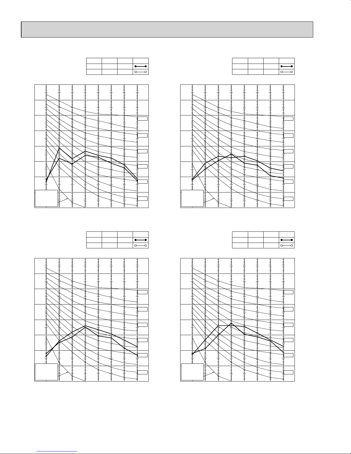
CoolingHigh
FUNCTION
FAN SPEED
HeatingHigh
54
SPL(dB(A))58LINE
90
80
70
60
50
40
30
20
10
63 125 250 500 1000 2000 4000 8000
APPROXIMATE
THRESHOLD OF
HEARING FOR
CONTINUOUS
NOISE
NC-60
NC-50
NC-40
NC-30
NC-20
NC-70
OCTAVE BAND SOUND PRESSURE LEVEL, 0dB = 0.0002 MICRO BAR
BAND CENTER FREQUENCIES, Hz
90
80
70
60
50
40
30
20
10
63 125 250 500 1000 2000 4000 8000
APPROXIMATE
THRESHOLD OF
HEARING FOR
CONTINUOUS
NOISE
NC-60
NC-50
NC-40
NC-30
NC-20
NC-70
OCTAVE BAND SOUND PRESSURE LEVEL, 0dB = 0.0002 MICRO BAR
BAND CENTER FREQUENCIES, Hz
CoolingHigh
FUNCTION
FAN SPEED
HeatingHigh
54
SPL(dB(A))58LINE
CoolingHigh
FUNCTION
FAN SPEED
HeatingHigh
56
SPL(dB(A))58LINE
90
80
70
60
50
40
30
20
10
63 125 250 500 1000 2000 4000 8000
APPROXIMATE
THRESHOLD OF
HEARING FOR
CONTINUOUS
NOISE
NC-60
NC-50
NC-40
NC-30
NC-20
NC-70
OCTAVE BAND SOUND PRESSURE LEVEL, 0dB = 0.0002 MICRO BAR
BAND CENTER FREQUENCIES, Hz
MXZ-5C42NA
OBH702A
MXZ-2C20NAHZ
MXZ-3C24NAHZ MXZ-3C30NAHZ
90
80
70
60
50
40
30
OCTAVE BAND SOUND PRESSURE LEVEL, 0dB = 0.0002 MICRO BAR
20
APPROXIMATE
THRESHOLD OF
HEARING FOR
CONTINUOUS
NOISE
10
FAN SPEED
FUNCTION
SPL(dB(A))58LINE
CoolingHigh
HeatingHigh
54
63 125 250 500 1000 2000 4000 8000
BAND CENTER FREQUENCIES, Hz
NC-70
NC-60
NC-50
NC-40
NC-30
NC-20
12
5
OBH702A
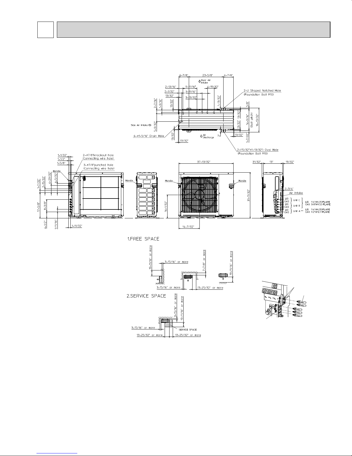
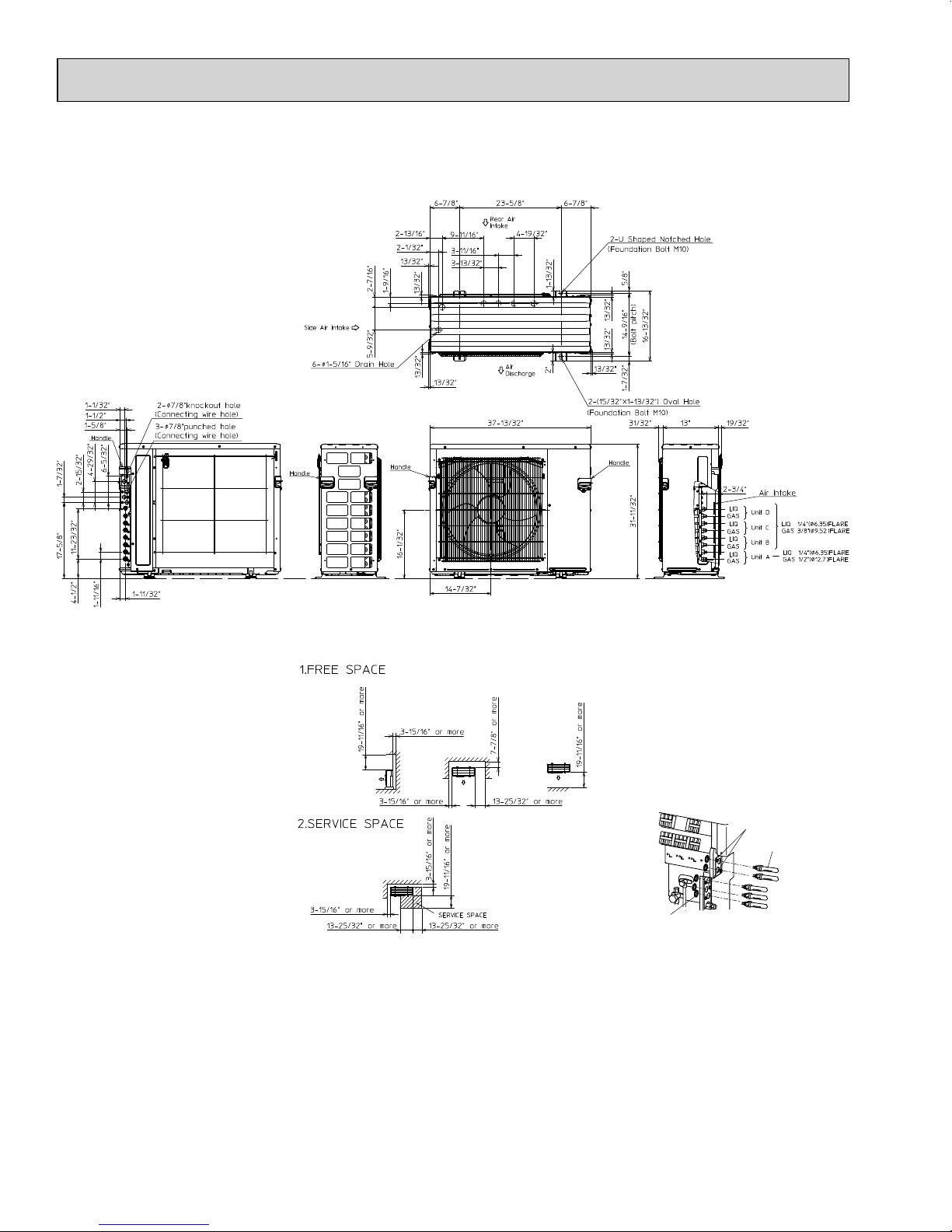
OUTLINES AND DIMENSIONS
MXZ-3C24NA
MXZ-3C30NA
Unit: inch (mm)
Conduit plates
Conduit connector
Lock nut
13
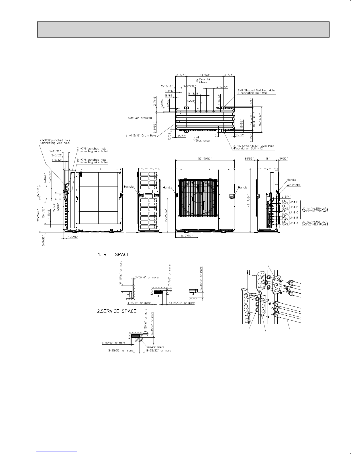
MXZ-4C36NA
OBH702A
Unit: inch (mm)
Conduit plates
Conduit connector
Lock nut
14
MXZ-5C42NA
OBH702A
Unit: inch (mm)
Conduit plate Top
Lock nut
Conduit plate Under
Conduit connector
15
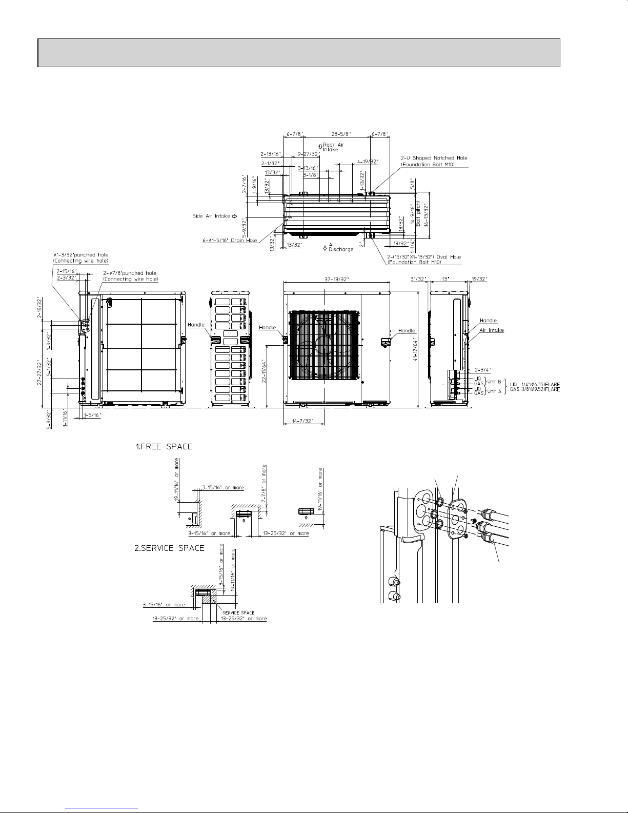
MXZ-2C20NAHZ
OBH702A
Unit: inch (mm)
Lock nut
Conduit plate
Conduit connector
16
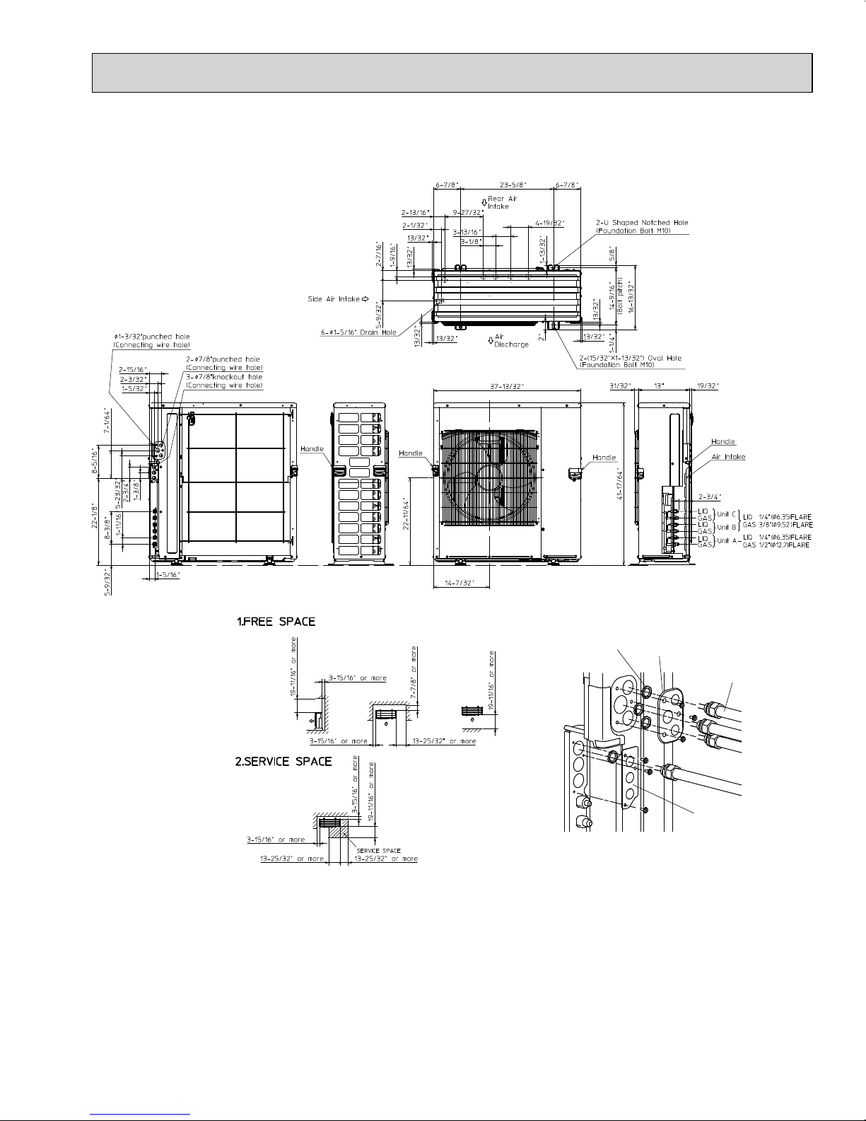
MXZ-3C24NAHZ
OBH702A
MXZ-3C30NAHZ
Unit: inch (mm)
Lock nut
Conduit plate Top
Conduit connector
Conduit plate Under
17
6
OBH702A
MXZ-3C24NA
MXZ-3C30NA
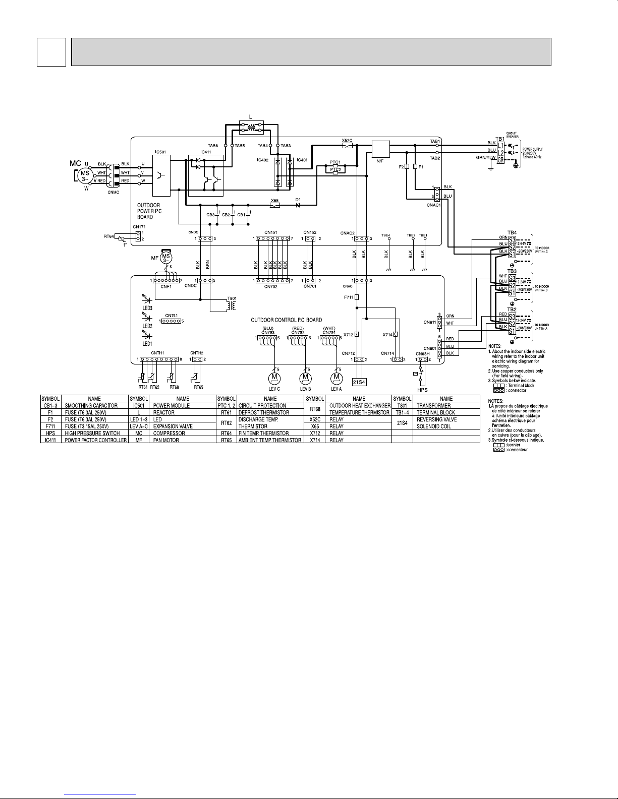
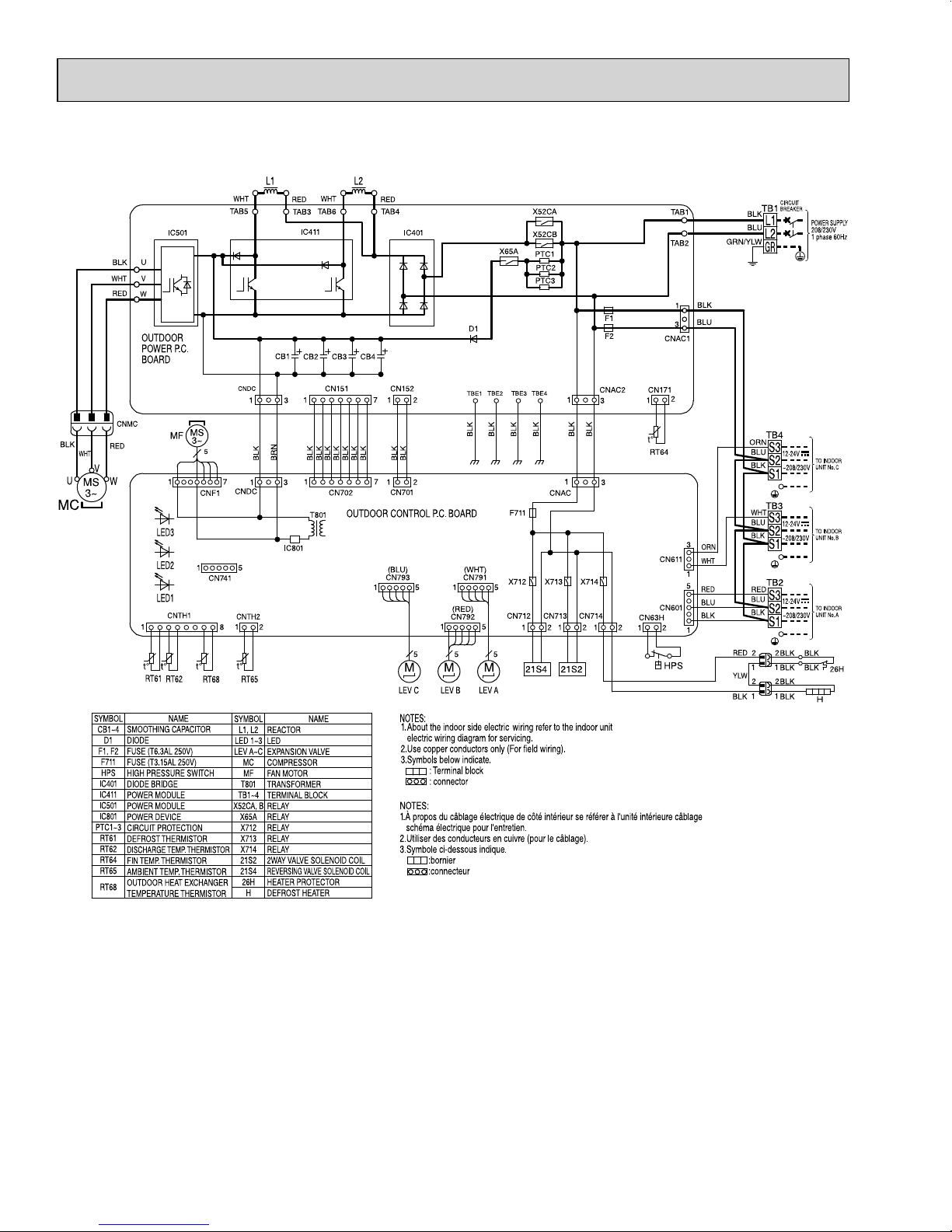
WIRING DIAGRAM
18
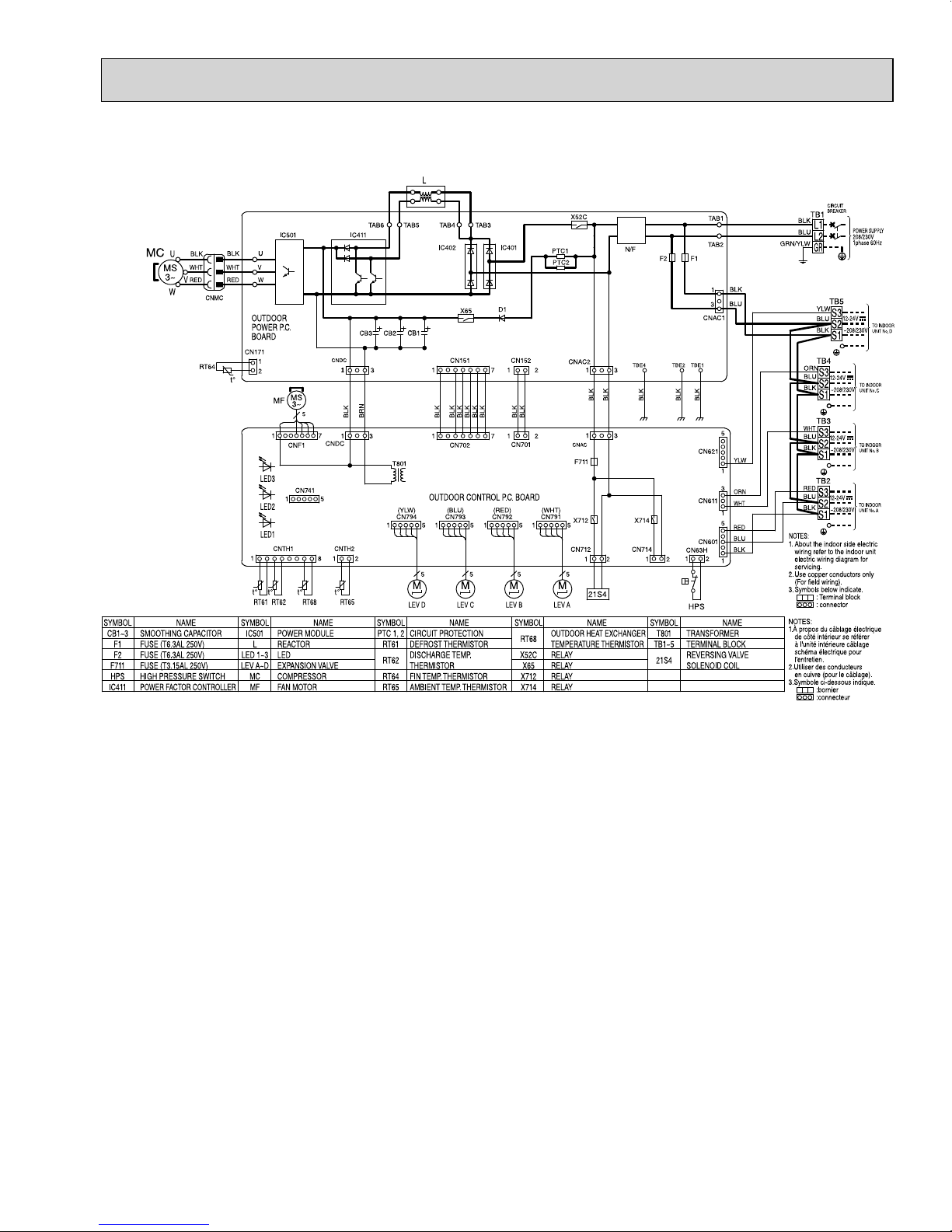
MXZ-4C36NA
OBH702A
19
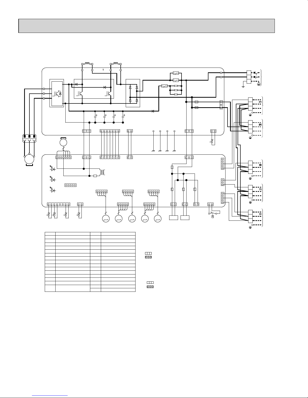
MXZ-5C42NA
OBH702A
U
BLK
WHT
V
RED
W
OUTDOOR
POWER P.C.
BOARD
CNMC
BLK
MC
RED
WHT
V
U
W
MS
3~
LED3
LED2
LED1
1
t°
t°
RT61
WHT WHT
TAB5
IC501
CNDC
13
MS
MF
3~
5
17
CNF1
15
CN741
CNTH1
t°
RT62
RT68
CNDC
CNTH2
1
8
t°
RT65
BLK
13
2
L1 L2
TAB6
TAB3
IC411
CB1
BRN
IC801
CB3 CB4
CB2
CN151 CN152
BLK
BLK
BLK
BLK
BLK
BLK
17
CN702
OUTDOOR CONTROL P.C. BOARD
T801
(BLK)
CN795
15
5
M
LEV D
LEV E
REDRED
TAB4
IC401
D1
2117
BLK
BLK
BLK
21
CN701
(BLU)
CN793
1515
(YLW)
CN794
15
555
5
M
M
TBE1
BLK
(WHT)
CN791
(RED)
CN792
15
MM
LEV C LEV B LEV A
X52CA
X52CB
X65A
PTC1
PTC2
PTC3
TBE4TBE2 TBE3
BLK
BLK
BLK
1
CNAC
F711
X712 X714
X713
CN712 CN714
CN713
21
21S4 21S2
CIRCUIT
BREAKER
TAB1
TAB2
BLK
CN171
1
t°
RT64
CN63H
CNAC1
2
CN622
CN611
CN601
21
1
BLU
3
5
GRY
YLW
1
3
ORN
WHT
1
5
RED
BLU
BLK
1
F1
F2
CNAC2
1
3
BLK
BLK
3
21
21
HPS
BLK
BLU
GRN/YLW
GRY
YLW
ORN
BLU
BLK
BLU
BLK
BLU
BLK
WHT
BLU
BLK
RED
BLU
BLK
TB1
L1
L2
GR
TB6
TB5
TB4
TB3
TB2
S3
S2
S1
S3
S2
S1
S3
S2
S1
S3
S2
S1
S3
S2
S1
12-24V
~208/230V
12-24V
~208/230V
12-24V
~208/230V
12-24V
~208/230V
12-24V
~208/230V
POWER SUPPLY
208/230V
1 phase 60Hz
TO INDOOR
UNIT No. E
TO INDOOR
UNIT No. D
TO INDOOR
UNIT No. C
TO INDOOR
UNIT No. B
TO INDOOR
UNIT No. A
SYMBOL
SMOOTHING CAPACITOR
CB1~4
D1
DIODE
F1, F2
FUSE (T6.3AL 250V)
F711
FUSE (T3.15AL 250V)
HPS
HIGH PRESSURE SWITCH
IC401
DIODE BRIDGE
IC411
POWER MODULE
IC501
POWER MODULE
IC801
POWER DEVICE
PTC1~3
CIRCUIT PROTECTION
RT61
DEFROST THERMISTOR
RT62
DISCHARGE TEMP . THERMIST OR
RT64
FIN TEMP. THERMISTOR
RT65
AMBIENT TEMP. THERMISTOR
OUTDOOR HEAT EXCHANGER
RT68
TEMPERATURE THERMISTOR
NAME
SYMBOL
L1, L2
LED 1~3
LEV A~E
MC
MF
T801
TB1~6
X52CA, B
X65A
X712
X713
X714
21S2
21S4
NAME
REACTOR
LED
EXPANSION VALVE
COMPRESSOR
FAN MOTOR
TRANSFORMER
TERMINAL BLOCK
RELAY
RELAY
RELAY
RELAY
RELAY
2WAY VALVE SOLENOID COIL
REVERSING VALVE SOLENOID COIL
NOTES:
1.About the indoor side electric wiring refer to the indoor unit
electric wiring diagram for servicing.
2.Use copper conductors only (For field wiring).
3.Symbols below indicate.
: Terminal block
: connector
NOTES:
1.À propos du câblage électrique de côté intérieur se référer à l'unité intérieure câblage
schéma électrique pour l'entretien.
2.Utiliser des conducteurs en cuivre (pour le câblage).
3.Symbole ci-dessous indique.
:bornier
:connecteur
20
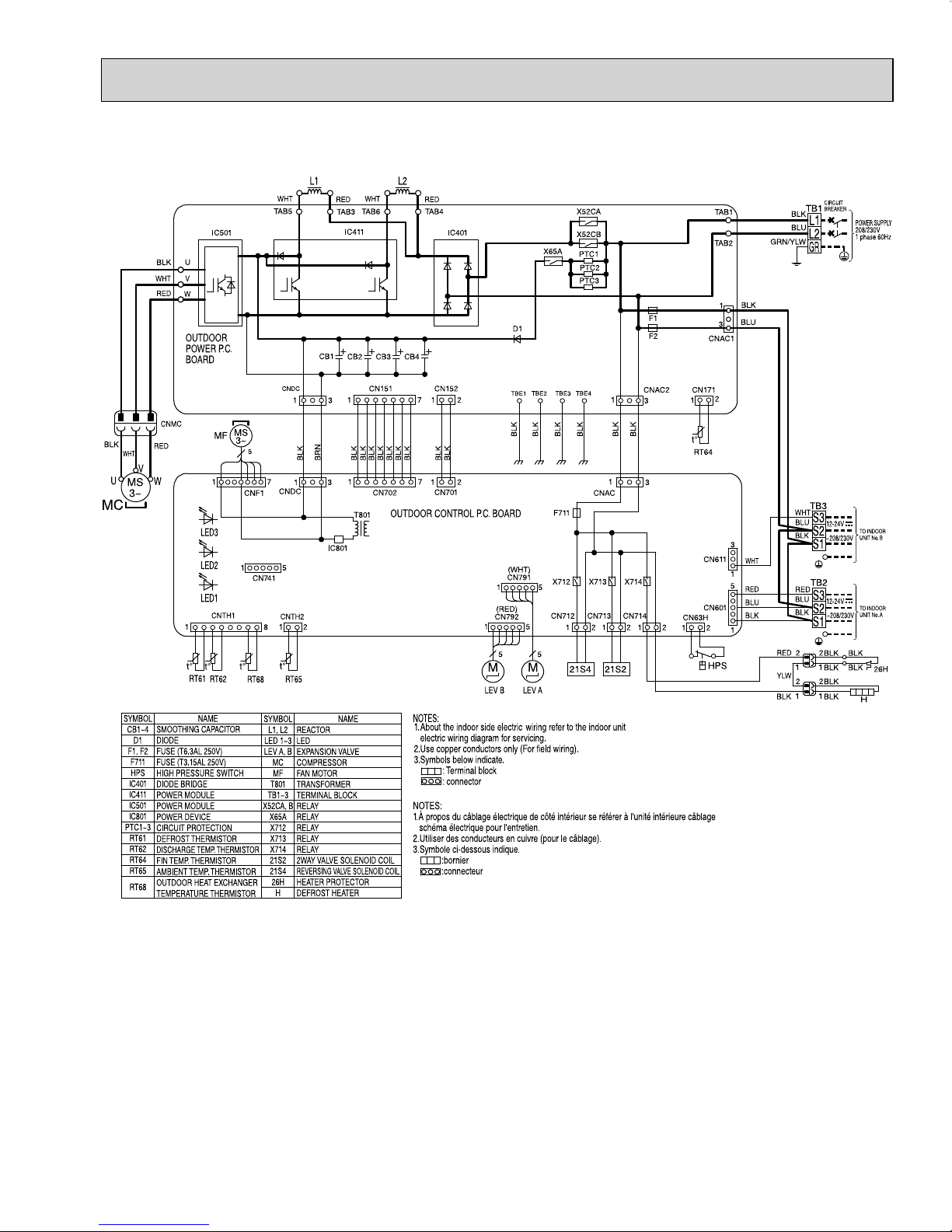
MXZ-2C20NAHZ
OBH702A
21
MXZ-3C24NAHZ
OBH702A
MXZ-3C30NAHZ
22
7
OBH702A
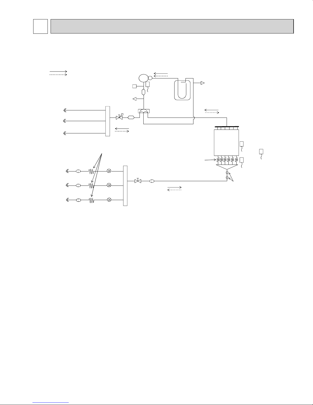
REFRIGERANT SYSTEM DIAGRAM
MXZ-3C24NA
MXZ-3C30NA
R.V.coil
OFF Refrigerant flow in heating
ON Refrigerant flow in cooling
Union
Union
ĭ1/4
ĭ1/4
ĭ1/4
ĭ1/2
ĭ3/8
ĭ3/8
Strainer
#100
Strainer
#100
Strainer
#100
Indoor unit A
Indoor unit B
Indoor unit C
Indoor unit A
Indoor unit B
Indoor unit C
High pressure switch
Header(Gas)
Capillary tube
O.D.0.16 x I.D.0.11 x 3.94
(Ø4.0 x Ø2.8 x 100)
LEVA
LEVB
LEVC
Compressor
Muffler
Service port
Stop valve
(with service port)
Sub
muffler
Stop valve
Compressor shell
temperature
thermistor
RT62
4-way valve
Strainer
#100
Accumulator
Capillary tube
Service port
Distributor
Header (Evaporator)
Outdoor
heat exchanger
Outdoor
heat exchanger temperature
thermistor
RT68
Defrost
temperature
thermistor
RT61
Strainer
#50
Unit: inch (mm)
Ambient
temperature
thermistor
RT65
23
Operating Range MXZ-3C24NA MXZ-3C30NA
Cooling
Heating
Maximum
Minimum
Maximum
Minimum
Indoor intake air temperature
95°FDB, 71°FWB
67°FDB, 57°FWB
80°FDB, 67°FWB
70°FDB, 60°FWB
Outdoor intake air temperature
115°FDB
14°FDB
75°FDB, 65°FWB
6°FDB, 5°FWB
OBH702A
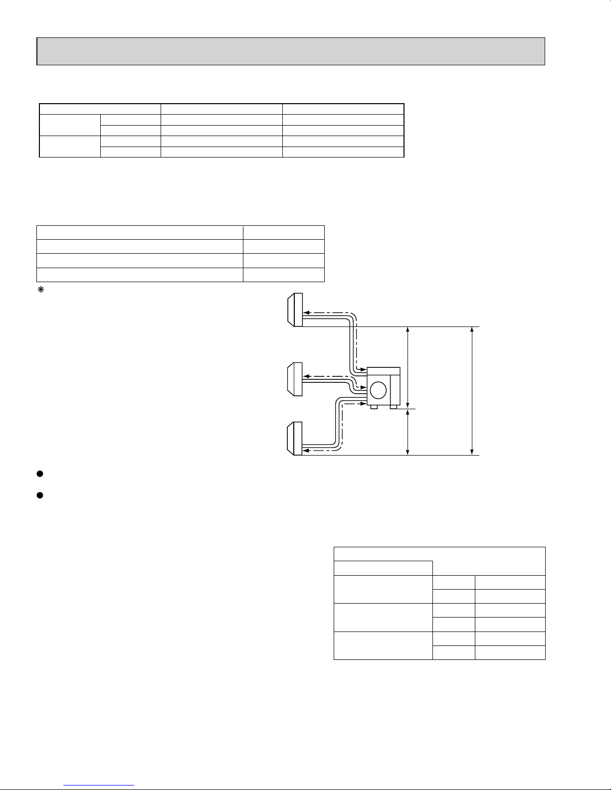
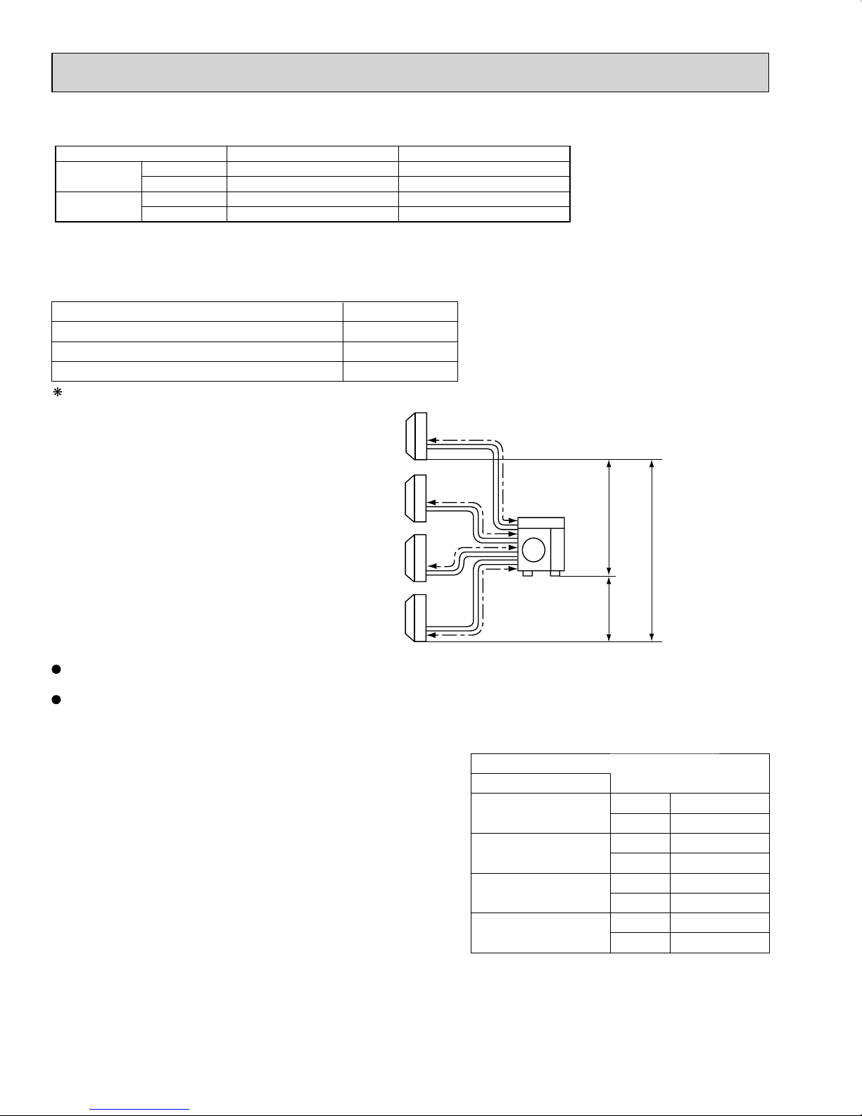
MAX. REFRIGERANT PIPING LENGTH & PIPE SIZE SELECTION
MXZ-3C24NA MXZ-3C30NA
Piping length each indoor unit (a, b, c) 82 ft. MAX.
Total piping length (a+b+c) 230 ft. MAX.
Bending point for each unit 25 MAX.
Total bending point 70 MAX.
It is irrelevant which unit is higher.
Indoor
units
a
Outdoor
c
unit
Max. height difference
49 ft.
49 ft.
b
Refrigerant pipe diameter is different according to indoor unit to be connected. When using extension pipes, refer to the
tables below.
When the diameter of refrigerant pipe is different from that of outdoor unit union, use optional Different-diameter pipe.
For further information on Different-diameter pipe, refer to "PARTS CATALOG".
For
Indoor unit A
Indoor unit B
Indoor unit C
49 ft.
Unit : inch
Outdoor unit union diameter
Liquid 1/4
Gas 1/2
Liquid 1/4
Gas 3/8
Liquid 1/4
Gas 3/8
24
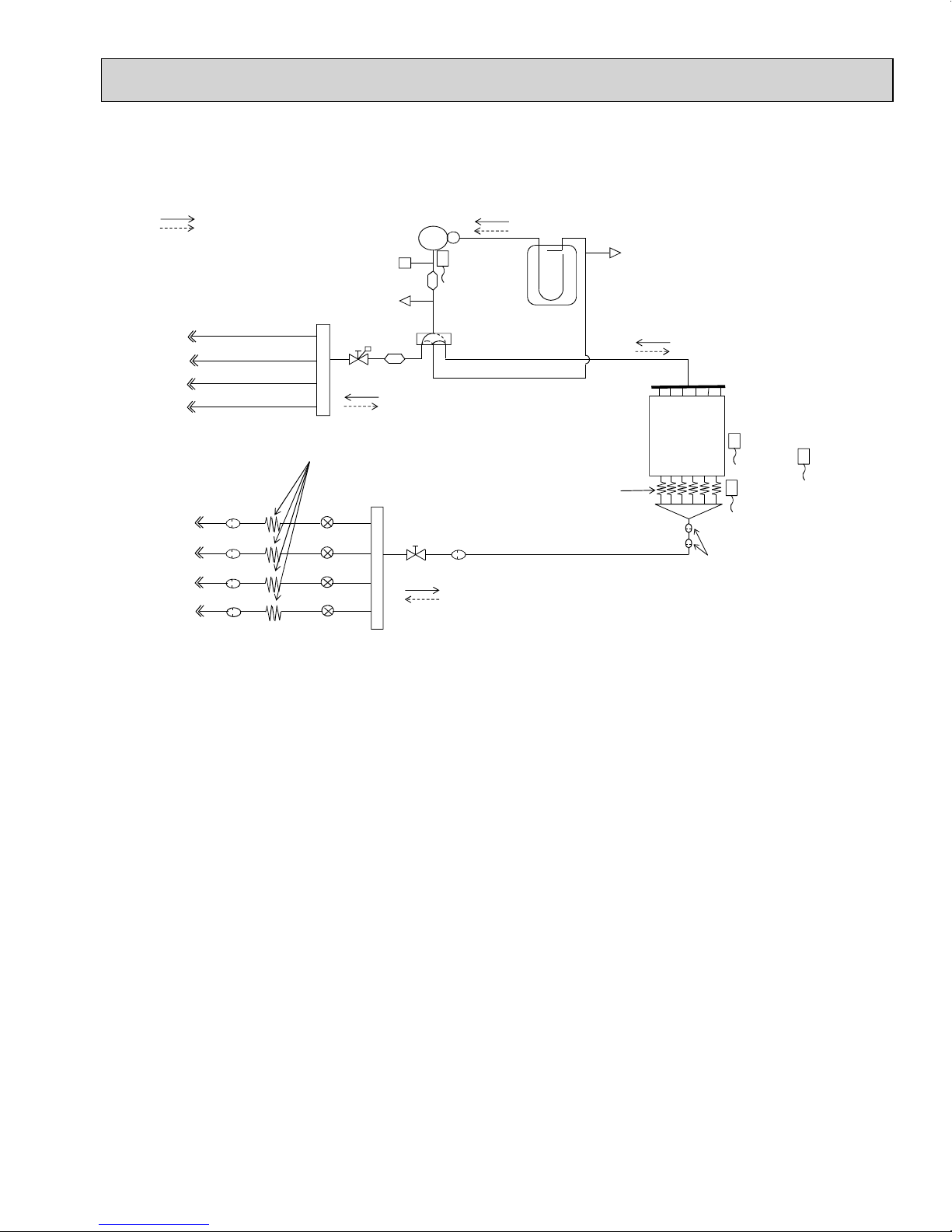
MXZ-4C36NA
OBH702A
R.V.coil
OFF Refrigerant flow in heating
ON Refrigerant flow in cooling
Union
Union
ĭ1/4
ĭ1/4
ĭ1/4
ĭ1/4
ĭ1/2
ĭ3/8
ĭ3/8
ĭ3/8
Strainer
#100
Strainer
#100
Strainer
#100
Strainer
#100
Indoor unit A
Indoor unit B
Indoor unit C
Indoor unit D
Indoor unit A
Indoor unit B
Indoor unit C
Indoor unit D
High pressure switch
Header(Gas)
Capillary tube
O.D.0.16 x I.D.0.11 x 3.94
(Ø4.0 x Ø2.8 x 100)
LEV A
LE
LEV C
LEV D
Compressor
Muffler
Service port
Stop valve
(with service port)
Sub
muffler
V B
Stop valve
Compressor shell
temperature
thermistor
RT62
4-way valve
Strainer
#100
Accumulator
Capillary tube
Service port
Distributor
Header (Evaporator)
Outdoor
heat exchanger
Outdoor
heat exchanger
temperature
thermistor
RT68
Defrost
temperature
thermistor
RT61
Strainer
#50
Unit: inch (mm)
Ambient
temperature
thermistor
RT65
25
Operating Range MXZ-4C36NA
Cooling
Heating
Maximum
Minimum
Maximum
Minimum
Indoor intake air temperature
95°FDB, 71°FWB
67°FDB, 57°FWB
80°FDB, 67°FWB
70°FDB, 60°FWB
Outdoor intake air temperature
115°FDB
14°FDB
75°FDB, 65°FWB
6°FDB, 5°FWB
OBH702A
MAX. REFRIGERANT PIPING LENGTH & PIPE SIZE SELECTION
MXZ-4C36NA
Piping length each indoor unit (a, b, c, d) 82 ft. MAX.
Total piping length (a+b+c+d) 230 ft. MAX.
Bending point for each unit 25 MAX.
Total bending point 70 MAX.
It is irrelevant which unit is higher.
Indoor
units
Refrigerant pipe diameter is different according to indoor unit to be connected. When using extension pipes, refer to the
tables below.
When the diameter of refrigerant pipe is different from that of outdoor unit union, use optional Different-diameter pipe.
For further information on Different-diameter pipe, refer to "PARTS CATALOG".
a
Max. height difference
b
c
d
Outdoor
unit
49 ft.
Outdoor unit union diameter
For
Indoor unit A
Indoor unit B
Indoor unit C
Indoor unit D
49 ft.
49 ft.
Unit : inch
Liquid 1/4
Gas 1/2
Liquid 1/4
Gas 3/8
Liquid 1/4
Gas 3/8
Liquid 1/4
Gas 3/8
26
 Loading...