

Mitsubishi MXZ-3E54VA-ET1, MXZ-4E72VA-E1, MXZ-3E54VA-ER1, MXZ-3E68VA-ER1, MXZ-3E68VA-E1 Service Manual
...
HFC
utilized
R410A
SERVICE MANUAL
No. OBH723
REVISED EDITION-D
OUTDOOR UNIT
NOTE:
RoHS compliant products have <G> mark
on the spec name plate.
PARTS CATALOG (OBB723)
Models
MXZ-3E54VA
-
E1,
ET1, ER1
MXZ-3E68VA
-
E1,
ET1, ER1
MXZ-4E72VA
-
E1,
ET1, ER1
MXZ-4E83VA
-
E1, E2, E3,
ET1, ET2, ET3, ER1, ER2
MXZ-5E102VA
-
E1, E2, E3,
ET1, ET2, ET3, ER1, ER2
MXZ-2E53VAHZ
-
E1,
ER1
MXZ-4E83VAHZ
-
E1, E2,
ER1, ER2
Indoor unit service manual
MSZ-EF•VE Series (OBH589)
MSZ-SF•VA Series (OBH555)
MSZ-SF•VE Series (OBH600)
MSZ-FD•VA Series (OBH488)
MSZ-FH•VE Series (OBH623)
MSZ-GA•VA Series (OB378)
MSZ-GE•VA Series (OBH515)
MSZ-GF•VE Series (OBH634)
MFZ-KA•VA Series (OB409)
MFZ-KJ•VE Series (OBH666)
MLZ-KA•VA Series (OBH483)
SLZ-KA•VA Series (OC320)
SEZ-KD•VA Series (HWE07110)
PLA-RP•BA Series (OCH412)
PCA-RP•KA Series (OCH454)
PEAD-RP•JA Series (HWE08130)
CONTENTS
1. TECHNICAL CHANGES ···································3
2. PART NAMES AND FUNCTIONS ·····················4
3. SPECIFICATION ················································5
4. NOISE CRITERIA CURVES ····························12
5. OUTLINES AND DIMENSIONS ······················14
6. WIRING DIAGRAM ··········································20
7. REFRIGERANT SYSTEM DIAGRAM ·············44
8. PERFORMANCE CURVES ·····························52
9. ACTUATOR CONTROL ···································82
10. SERVICE FUNCTIONS ····································83
11. TROUBLESHOOTING ·····································86
12. DISASSEMBLY INSTRUCTIONS ··················108
INDOOR UNITS COMBINATION SHEETS
MXZ-4E83VA
MXZ-5E102VA
MXZ-2E53VAHZ
OBH723 REVISED EDITION-C is void.
Revision D:
• MXZ-4E83VA- E3,
ET3, ER2
, MXZ-5E102VA-
E3, ET3, ER2
and MXZ-4E83VAHZ- E2,
ER2
have been added.
2
<Preparation before the repair service>
Prepare the proper tools.
Prepare the proper protectors.
Provide adequate ventilation.
After stopping the operation of the air conditioner, turn off the power-supply breaker and remove the power plug.
Discharge the capacitor before the work involving the electric parts.
<Precautions during the repair service>
Do not perform the work involving the electric parts with wet hands.
Do not pour water into the electric parts.
Do not touch the refrigerant.
Do not touch the hot or cold areas in the refrigeration cycle.
When the repair or the inspection of the circuit needs to be done without turning off the power, exercise great caution not to
touch the live parts.
Use the specif ed refrigerant only
Never use any refrigerant other than that specified.
Doing so may cause a burst, an explosion, or fire when the unit is being used, serviced, or disposed of.
Correct refrigerant is specified in the manuals and on the spec labels provided with our products.
We will not be held responsible for mechanical failure, system malfunction, unit breakdown or accidents caused by
failure to follow the instructions.
Revision A:
• MXZ-2E53VAHZ- E1 and MXZ-4E83VAHZ- E1 have been added.
• Values of air flow and fan speed for MXZ-5E102VA-
E1, ET1
have been modified.
Revision B:
• MXZ-3E54VA- E1,
ET1
, MXZ-3E68VA- E1,
ET1
, and MXZ-4E72VA- E1,
ET1
have been added.
Revision C:
• MXZ-3E54VA-
ER1
, MXZ-3E68VA-
ER1
, MXZ-4E72VA-
ER1
, MXZ-4E83VA- E2,
ET2, ER1
, MXZ-5E102VA- E2,
ET2, ER1
,
MXZ-2E53VAHZ-
ER1
and MXZ-4E83VAHZ-
ER1
have been added.
Revision D:
• MXZ-4E83VA- E3,
ET3, ER2
, MXZ-5E102VA- E3,
ET3, ER2
and MXZ-4E83VAHZ- E2,
ER2
have been added.
OBH723D
3
TECHNICAL CHANGES
1
MXZ-4E83VA -E1,
ET1, ER1
MXZ-5E102VA -E1,
ET1, ER1
1. New model
MXZ-2E53VAHZ -E1,
ER1
1. New model
MXZ-4E83VAHZ -E1,
ER1
1. New model
MXZ-3E54VA -E1,
ET1, ER1
MXZ-3E68VA -E1,
ET1, ER1
MXZ-4E72VA -E1,
ET1, ER1
1. New model
MXZ-4E83VA -E1,
ET1
MXZ-4E83VA -
E2, ET2
1. Fan motor has been changed.
2. Outdoor control P.C. board has been changed.
MXZ-5E102VA -E1,
ET1
MXZ-5E102VA -
E2, ET2
1. Fan motor has been changed.
2. Outdoor control P.C. board has been changed.
MXZ-4E83VA -
ER1
MXZ-4E83VA -
ER2
1. Outdoor control P.C. board has been changed.
MXZ-4E83VA -E2,
ET2
MXZ-4E83VA -
E3, ET3
1. Outdoor control P.C. board has been changed.
MXZ-5E102VA -
ER1
MXZ-5E102VA -
ER2
1. Outdoor control P.C. board has been changed.
MXZ-5E102VA -E2,
ET2
MXZ-5E102VA -
E3, ET3
1. Outdoor control P.C. board has been changed.
MXZ-4E83VAHZ -E1,
ER1
MXZ-4E83VAHZ -
E2, ER2
1. Outdoor control P.C. board has been changed.
OBH723D
4
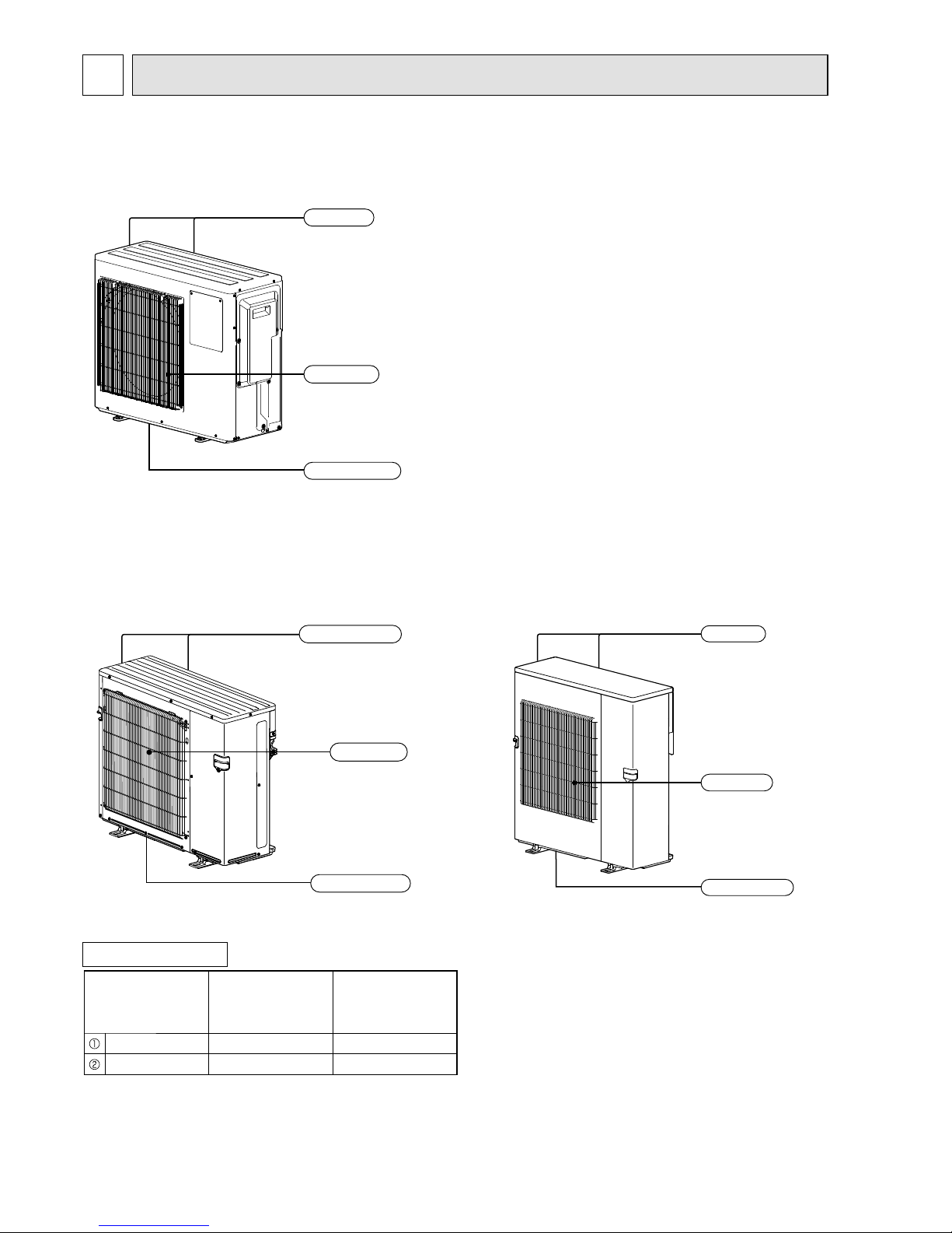
PART NAMES AND FUNCTIONS
2
MXZ-4E83VA
MXZ-5E102VA
MXZ-2E53VAHZ
Air outlet
Drain outlet
Air inlet
(Back and side)
ACCESSORIES
Model
MXZ-3E54VA
MXZ-3E68VA
MXZ-4E72VA
MXZ-4E83VA
MXZ-5E102VA
Drain socket 1 1
Drain cap 2 5
Air outlet
Drain outlet
Air inlet
(Back and side)
MXZ-4E83VAHZ
Air outlet
Drain outlet
Air inlet
(Back and side)
MXZ-3E54VA
MXZ-3E68VA
MXZ-4E72VA
OBH723D
5
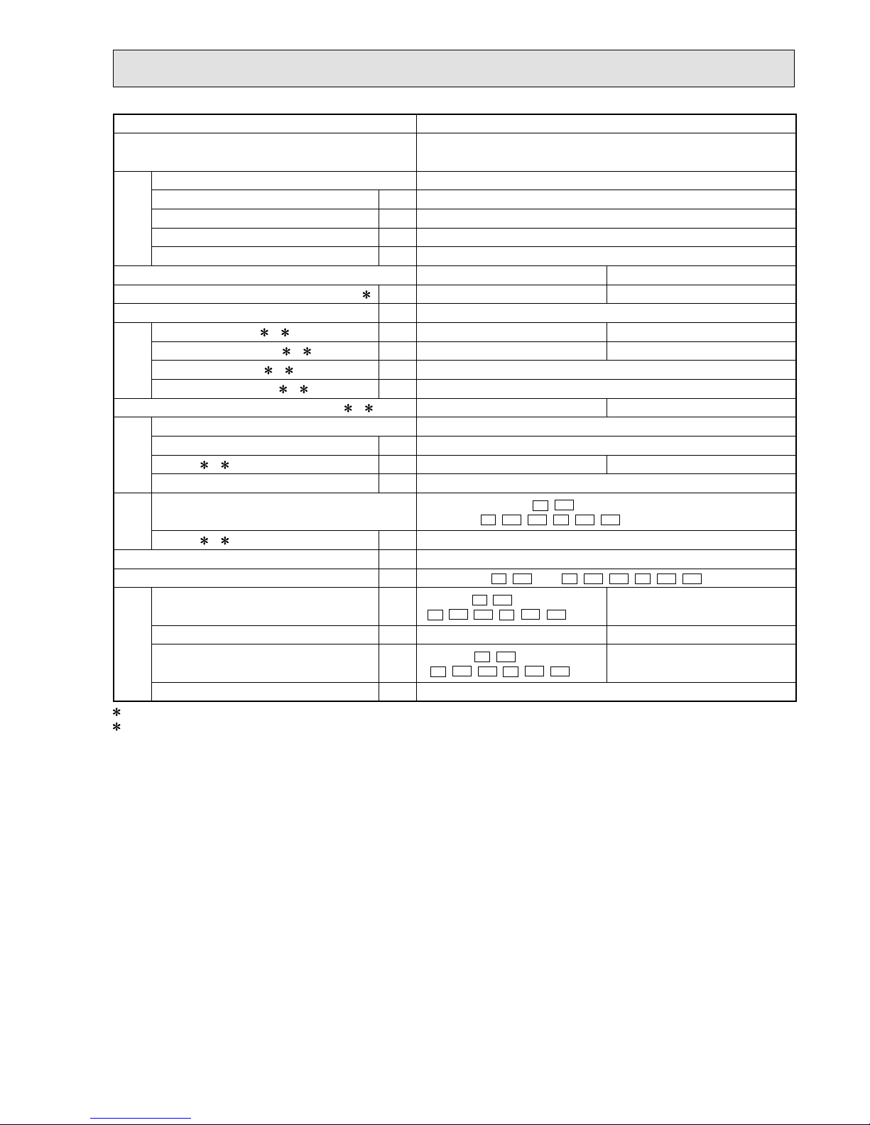
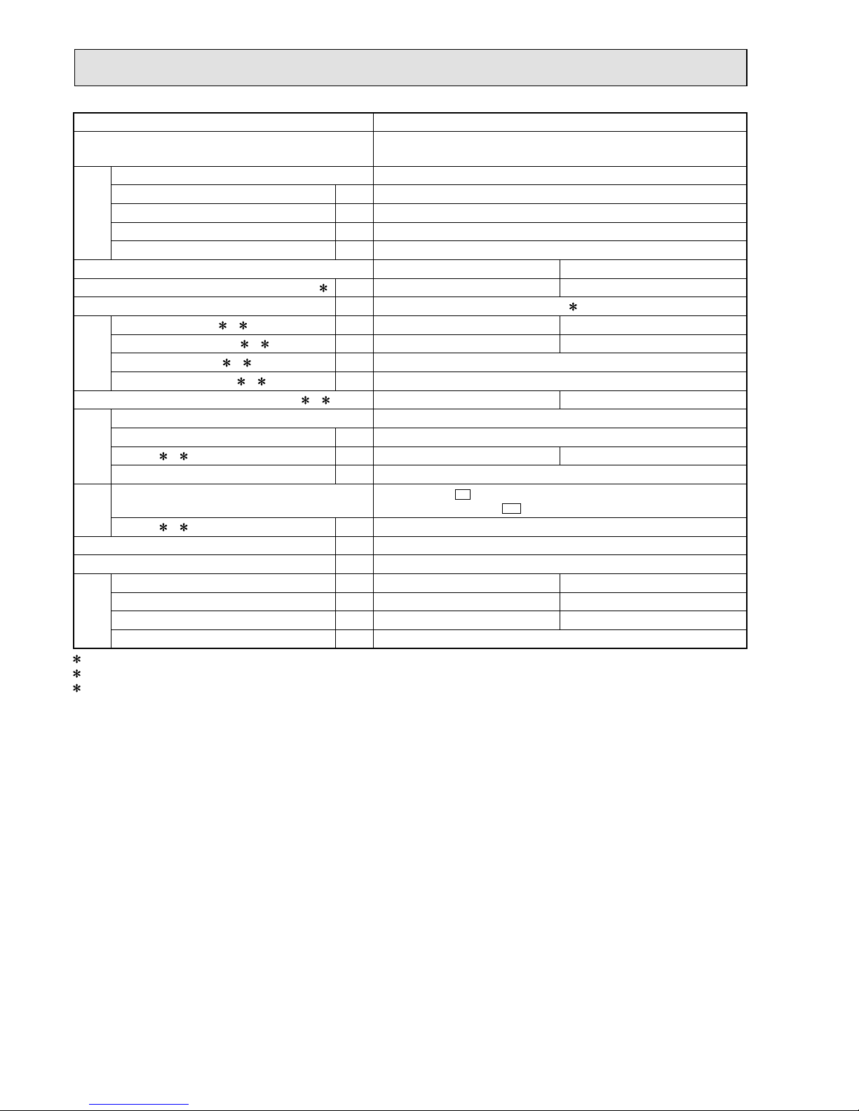
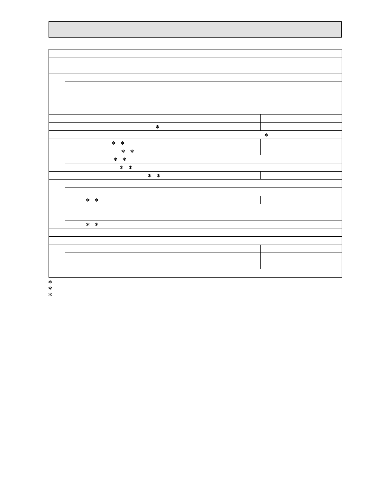
SPECIFICATION
3
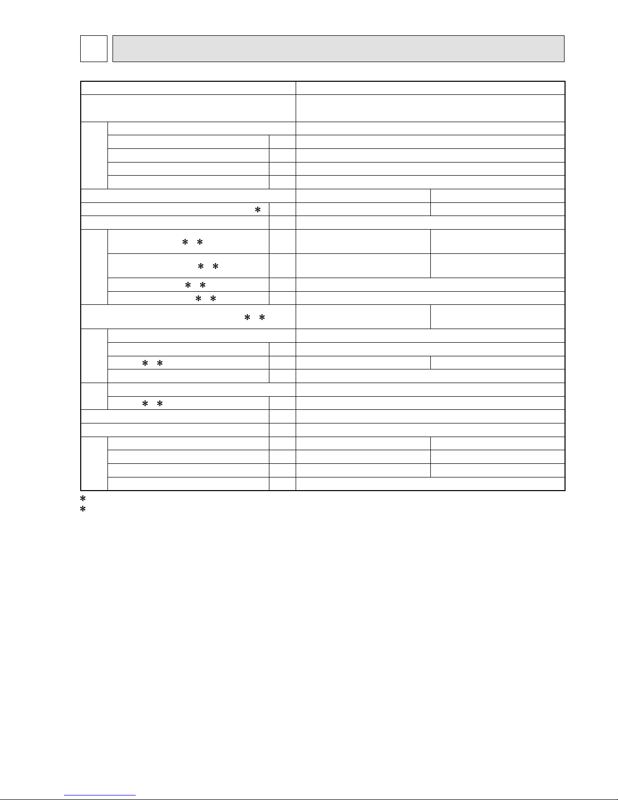
Outdoor model MXZ-3E54VA
Outdoor unit power supply
Single phase
230 V, 50 Hz
System
Indoor units number 2 to 3
Piping total length m Max. 50
Connecting pipe length m Max. 25
Height difference (Indoor ~ Outdoor) m Refer to 7 REFRIGERANT SYSTEM DIAGRAM.
Height difference (Indoor ~ Indoor) m Refer to 7 REFRIGERANT SYSTEM DIAGRAM.
Function Cooling Heating
Capacity Rated frequency (Min.-Max.)
2 kW 5.4 (2.9 - 6.8) 7.0 (2.6 - 9.0)
Breaker capacity A 25
Electrical
data
Power input (Total) 1, 2 W 1,350 1,590
Running current (Total)
1, 2 A 5.9 7.0
Power factor (Total)
1, 2% 99
Starting current (Total)
1, 2 A 7.0
Coeff cient of performance (C.O.P) (Total)
1, 2 4.00 4.40
Compressor
Model SNB130FGBH1T
Output W 1,400
Current
1, 2 A 5.72 6.62
Refrigeration oil (Model) L 0.7 (NEO22)
Fan
motor
Model SIC-71FW-F764-2
Current
1, 2 A 0.2
Dimensions W x H x D mm 840 x 710 x 330
Weight kg 58
Special
remarks
Air f ow (Rated) m3 /h 2,334 2,376
Sound level (Rated) dB(A) 50 53
Fan speed (Rated) rpm 650 660
Refrigerant f lling capacity (R410A) kg 2.7
1 Measured under rated operating frequency.
2 When connected with indoor units below.
MSZ-EF18VE + MSZ-EF18VE + MSZ-EF18VE
NOTE: Test conditions are based on ISO 5151. (Refrigerant piping length (one way): 5 m)
COOLING INDOOR Dry-bulb temperature 27.0 °C Wet-bulb temperature 19.0 °C
OUTDOOR Dry-bulb temperature 35.0 °C Wet-bulb temperature 24.0 °C
HEATING INDOOR Dry-bulb temperature 20.0 °C
OUTDOOR Dry-bulb temperature 7.0 °C Wet-bulb temperature 6.0 °C
OBH723D
6
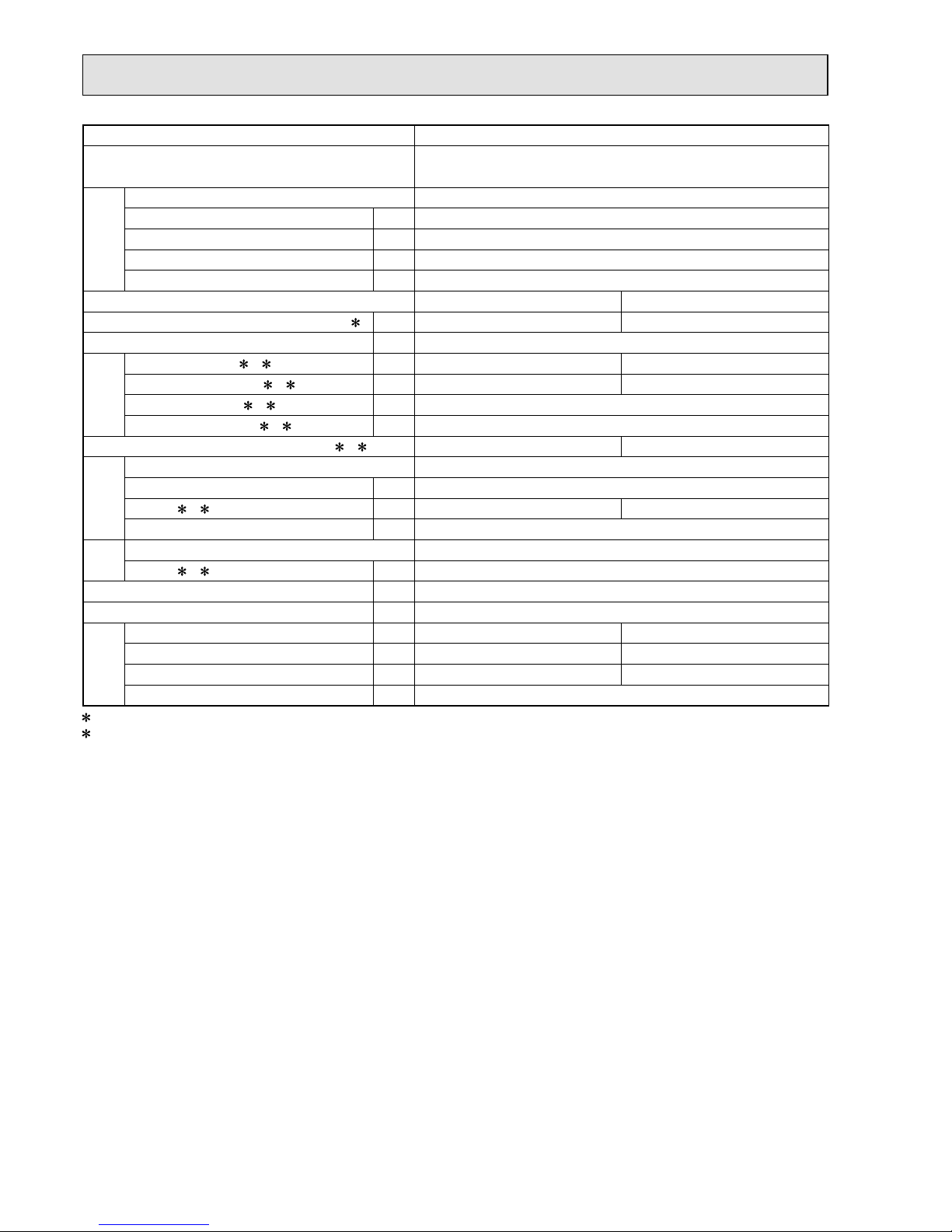
Outdoor model MXZ-3E68VA
Outdoor unit power supply
Single phase
230 V, 50 Hz
System
Indoor units number 2 to 3
Piping total length m Max. 60
Connecting pipe length m Max. 25
Height difference (Indoor ~ Outdoor) m Refer to 7 REFRIGERANT SYSTEM DIAGRAM.
Height difference (Indoor ~ Indoor) m Refer to 7 REFRIGERANT SYSTEM DIAGRAM.
Function Cooling Heating
Capacity Rated frequency (Min.-Max.)
2 kW 6.8 (2.9 - 8.4) 8.6 (2.6 - 10.6)
Breaker capacity A 25
Electrical
data
Power input (Total) 1, 2 W 2,190 2,380
Running current (Total)
1, 2 A 9.6 10.5
Power factor (Total)
1, 2% 99
Starting current (Total)
1, 2 A 10.5
Coeff cient of performance (C.O.P) (Total)
1, 2 3.11 3.61
Compressor
Model SNB172FEGH1T
Output W 1,800
Current
1, 2 A 9.22 10.12
Refrigeration oil (Model) L 0.7 (NEO22)
Fan
motor
Model SIC-71FW-F764-2
Current
1, 2 A 0.2
Dimensions W x H x D mm 840 x 710 x 330
Weight kg 58
Special
remarks
Air f ow (Rated) m3 /h 2,334 2,376
Sound level (Rated) dB(A) 50 53
Fan speed (Rated) rpm 650 660
Refrigerant f lling capacity (R410A) kg 2.7
1 Measured under rated operating frequency.
2 When connected with indoor units below.
MSZ-EF18VE + MSZ-EF25VE + MSZ-EF25VE
NOTE: Test conditions are based on ISO 5151. (Refrigerant piping length (one way): 5 m)
COOLING INDOOR Dry-bulb temperature 27.0 °C Wet-bulb temperature 19.0 °C
OUTDOOR Dry-bulb temperature 35.0 °C Wet-bulb temperature 24.0 °C
HEATING INDOOR Dry-bulb temperature 20.0 °C
OUTDOOR Dry-bulb temperature 7.0 °C Wet-bulb temperature 6.0 °C
OBH723D
7
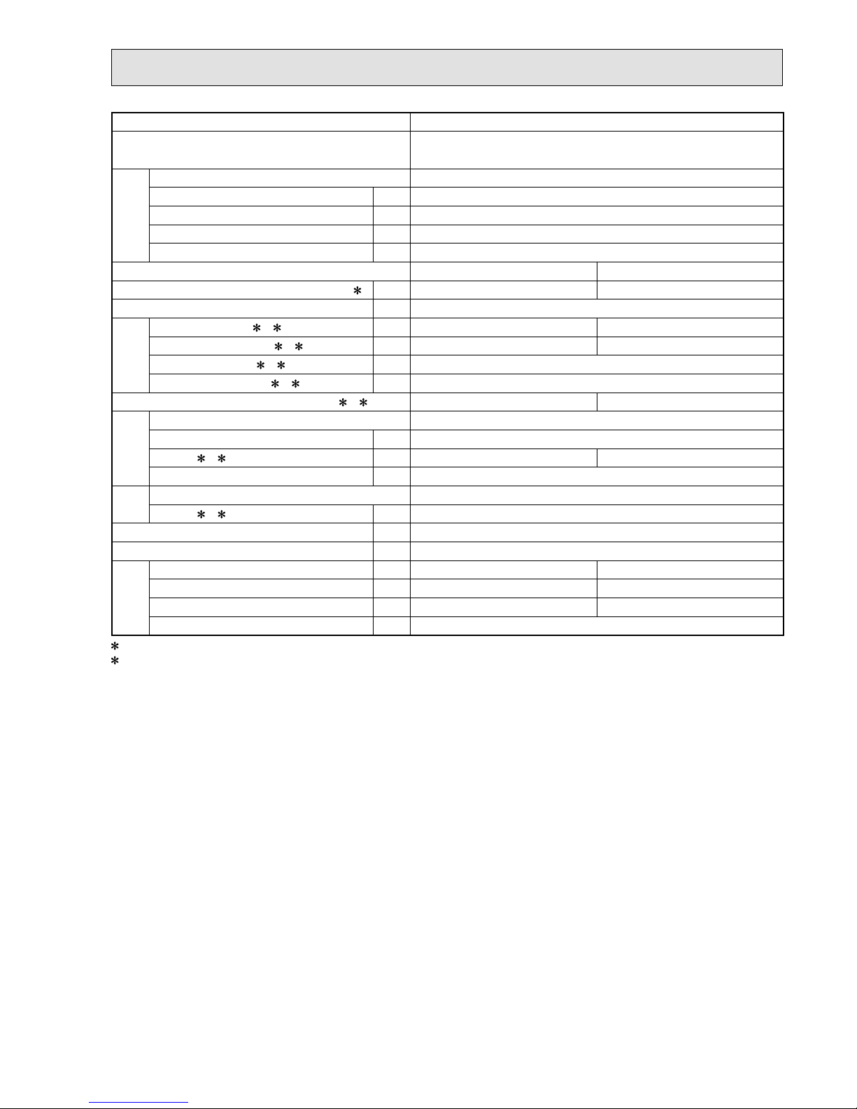
Outdoor model MXZ-4E72VA
Outdoor unit power supply
Single phase
230 V, 50 Hz
System
Indoor units number 2 to 4
Piping total length m Max. 60
Connecting pipe length m Max. 25
Height difference (Indoor ~ Outdoor) m Refer to 7 REFRIGERANT SYSTEM DIAGRAM.
Height difference (Indoor ~ Indoor) m Refer to 7 REFRIGERANT SYSTEM DIAGRAM.
Function Cooling Heating
Capacity Rated frequency (Min.-Max.)
2 kW 7.2 (3.7 - 8.8) 8.6 (3.4 - 10.7)
Breaker capacity A 25
Electrical
data
Power input (Total) 1, 2 W 2,250 2,280
Running current (Total)
1, 2 A 9.9 10.0
Power factor (Total)
1, 2% 99
Starting current (Total)
1, 2 A 10.0
Coeff cient of performance (C.O.P) (Total)
1, 2 3.20 3.77
Compressor
Model SNB172FEGH1T
Output W 2,000
Current
1, 2 A 9.46 9.56
Refrigeration oil (Model) L 0.7 (NEO22)
Fan
motor
Model SIC-71FW-F764-2
Current
1, 2 A 0.2
Dimensions W x H x D mm 840 x 710 x 330
Weight kg 59
Special
remarks
Air f ow (Rated) m3 /h 2,334 2,376
Sound level (Rated) dB(A) 50 53
Fan speed (Rated) rpm 650 660
Refrigerant f lling capacity (R410A) kg 2.7
1 Measured under rated operating frequency.
2 When connected with indoor units below.
MSZ-EF18VE + MSZ-EF18VE + MSZ-EF18VE + MSZ-EF18VE
NOTE: Test conditions are based on ISO 5151. (Refrigerant piping length (one way): 5 m)
COOLING INDOOR Dry-bulb temperature 27.0 °C Wet-bulb temperature 19.0 °C
OUTDOOR Dry-bulb temperature 35.0 °C Wet-bulb temperature 24.0 °C
HEATING INDOOR Dry-bulb temperature 20.0 °C
OUTDOOR Dry-bulb temperature 7.0 °C Wet-bulb temperature 6.0 °C
OBH723D
8
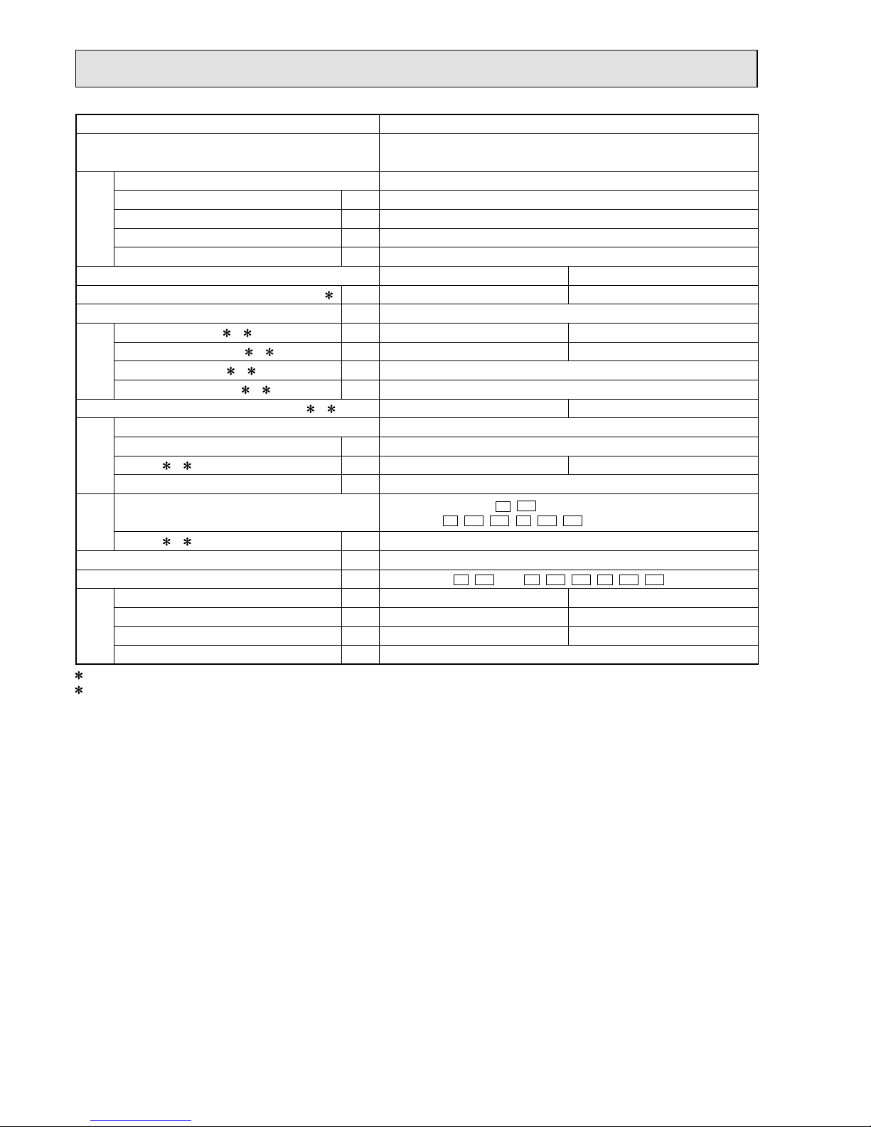
Outdoor model MXZ-4E83VA
Outdoor unit power supply
Single phase
230 V, 50 Hz
System
Indoor units number 2 to 4
Piping total length m Max. 70
Connecting pipe length m Max. 25
Height difference (Indoor ~ Outdoor) m Refer to 7 REFRIGERANT SYSTEM DIAGRAM.
Height difference (Indoor ~ Indoor) m Refer to 7 REFRIGERANT SYSTEM DIAGRAM.
Function Cooling Heating
Capacity Rated frequency (Min.-Max.)
2 kW 8.3 (3.7 - 9.2) 9.3 (3.4 - 11.6)
Breaker capacity A 25
Electrical
data
Power input (Total) 1, 2 W 2,440 2,000
Running current (Total)
1, 2 A 10.7 8.8
Power factor (Total)
1, 2% 99
Starting current (Total)
1, 2 A 10.7
Coeff cient of performance (C.O.P) (Total)
1, 2 3.40 4.65
Compressor
Model SNB220FAGMC
Output W 2,200
Current
1, 2 A 10.1 8.1
Refrigeration oil (Model) L 0.7 (FV50S)
Fan
motor
Model
E1
,
ET1
: SIC-81FW-D888-9
E2
,
ET2
,
ER1
, E3,
ET3
,
ER2
: SIC-88FWJ-D888-1
Current
1, 2 A 0.3
Dimensions W x H x D mm 950 x 796 x 330
Weight kg
E1
,
ET1
: 62 / E2,
ET2
,
ER1
, E3,
ET3
,
ER2
: 63
Special
remarks
Air f ow (Rated) m3 /h 3,336 3,336
Sound level (Rated) dB(A) 49 51
Fan speed (Rated) rpm 620 620
Refrigerant f lling capacity (R410A) kg 2.99
1 Measured under rated operating frequency.
2 When connected with below indoor units.
MSZ-EF18VE + MSZ-EF18VE + MSZ-EF22VE + MSZ-EF25VE
NOTE: Test conditions are based on ISO 5151. (Refrigerant piping length (one way): 5 m)
COOLING INDOOR Dry-bulb temperature 27.0°C Wet-bulb temperature 19.0°C
OUTDOOR Dry-bulb temperature 35.0°C Wet-bulb temperature 24.0°C
HEATING INDOOR Dry-bulb temperature 20.0°C
OUTDOOR Dry-bulb temperature 7.0°C Wet-bulb temperature 6.0°C
OBH723D
9
Outdoor model MXZ-5E102VA
Outdoor unit power supply
Single phase
230 V, 50 Hz
System
Indoor units number 2 to 5
Piping total length m Max. 80
Connecting pipe length m Max. 25
Height difference (Indoor ~ Outdoor) m Refer to 7 REFRIGERANT SYSTEM DIAGRAM.
Height difference (Indoor ~ Indoor) m Refer to 7 REFRIGERANT SYSTEM DIAGRAM.
Function Cooling Heating
Capacity Rated frequency (Min.-Max.)
2 kW 10.2 (3.9 - 11.0) 10.5 (4.1 - 14.0)
Breaker capacity A 25
Electrical
data
Power input (Total) 1, 2 W 3,150 2,340
Running current (Total)
1, 2 A 13.8 10.3
Power factor (Total)
1, 2% 99
Starting current (Total)
1, 2 A 13.8
Coeff cient of performance (C.O.P) (Total)
1, 2 3.24 4.49
Compressor
Model SNB220FAGMC
Output W 2,800
Current
1, 2 A 13.0 9.4
Refrigeration oil (Model) L 0.7 (FV50S)
Fan
motor
Model
E1
,
ET1
: SIC-81FW-D888-9
E2
,
ET2
,
ER1
, E3,
ET3
,
ER2
: SIC-88FWJ-D888-1
Current
1, 2 A 0.5
Dimensions W x H x D mm 950 x 796 x 330
Weight kg
E1
,
ET1
: 63 / E2,
ET2
,
ER1
, E3,
ET3
,
ER2
: 64
Special
remarks
Air f ow (Rated) m3 /h
E1
,
ET1
: 3,336 /
E2
,
ET2
,
ER1
,
E3,
ET3
,
ER2
: 3,906
4,080
Sound level (Rated) dB(A) 52 56
Fan speed (Rated) rpm
E1
,
ET1
: 620 /
E2
,
ET2
,
ER1
,
E3,
ET3
,
ER2
: 720
750
Refrigerant f lling capacity (R410A) kg 2.99
1 Measured under rated operating frequency.
2 When connected with below indoor units.
MSZ-EF18VE + MSZ-EF18VE + MSZ-EF22VE + MSZ-EF22VE + MSZ-EF22VE
NOTE: Test conditions are based on ISO 5151. (Refrigerant piping length (one way): 5 m)
COOLING INDOOR Dry-bulb temperature 27.0°C Wet-bulb temperature 19.0°C
OUTDOOR Dry-bulb temperature 35.0°C Wet-bulb temperature 24.0°C
HEATING INDOOR Dry-bulb temperature 20.0°C
OUTDOOR Dry-bulb temperature 7.0°C Wet-bulb temperature 6.0°C
OBH723D
10
Outdoor model MXZ-2E53VAHZ
Outdoor unit power supply
Single phase
230 V, 50 Hz
System
Indoor units number 2
Piping total length m Max. 30
Connecting pipe length m Max. 20
Height difference (Indoor ~ Outdoor) m Refer to 7 REFRIGERANT SYSTEM DIAGRAM.
Height difference (Indoor ~ Indoor) m Refer to 7 REFRIGERANT SYSTEM DIAGRAM.
Function Cooling Heating
Capacity Rated frequency (Min.-Max.)
2 kW 5.3 (1.1 - 6.0) 6.4 (1.0 - 7.0)
Breaker capacity A 16/25
3
Electrical
data
Power input (Total) 1, 2 W 1,290 1,360
Running current (Total)
1, 2 A 5.7 6.0
Power factor (Total)
1, 2% 98
Starting current (Total)
1, 2 A 6.0
Coeff cient of performance (C.O.P) (Total)
1, 2 4.11 4.71
Compressor
Model SNB220FAGMC
Output W 1,400
Current
1, 2 A 5.3 5.5
Refrigeration oil (Model) L 0.7 (FV50S)
Fan
motor
Model
E1
: SIC-81FW-D888-9, SIC-88FWJ-D888-1
ER1
: SIC-88FWJ-D888-1
Current 1, 2 A 0.3
Dimensions W x H x D mm 950 x 796 x 330
Weight kg 61
Special
remarks
Air f ow (Rated) m3 /h 2,820 2,820
Sound level (Rated) dB(A) 45 47
Fan speed (Rated) rpm 520 520
Refrigerant f lling capacity (R410A) kg 2.0
1 Measured under rated operating frequency.
2 When connected with below indoor units.
3 When the amount of current exceeds the allowed value.
MSZ-EF18VE + MSZ-EF35VE
NOTE: Test conditions are based on ISO 5151. (Refrigerant piping length (one way): 5 m)
COOLING INDOOR Dry-bulb temperature 27.0°C Wet-bulb temperature 19.0°C
OUTDOOR Dry-bulb temperature 35.0°C Wet-bulb temperature 24.0°C
HEATING INDOOR Dry-bulb temperature 20.0°C
OUTDOOR Dry-bulb temperature 7.0°C Wet-bulb temperature 6.0°C
OBH723D
11
Outdoor model MXZ-4E83VAHZ
Outdoor unit power supply
Single phase
230 V, 50 Hz
System
Indoor units number 2 to 4
Piping total length m Max. 70
Connecting pipe length m Max. 25
Height difference (Indoor ~ Outdoor) m Refer to 7 REFRIGERANT SYSTEM DIAGRAM.
Height difference (Indoor ~ Indoor) m Refer to 7 REFRIGERANT SYSTEM DIAGRAM.
Function Cooling Heating
Capacity Rated frequency (Min.-Max.)
2 kW 8.3 ( 3.5 - 9.2 ) 9.0 ( 3.5 - 11.6 )
Breaker capacity A 25/30
3
Electrical
data
Power input (Total) 1, 2 W 2,250 1,900
Running current (Total)
1, 2 A 9.9 8.3
Power factor (Total)
1, 2% 99
Starting current (Total)
1, 2 A 9.9
Coeff cient of performance (C.O.P) (Total)
1, 2 3.68 4.73
Compressor
Model MNB33FBTMC-L
Output W 2,200
Current
1, 2 A 9.30 7.60
Refrigeration oil (Model) L 1.10 (FV50S)
Fan
motor
Model SIC-81FW-D888-9,
SIC-88FWJ-D888-1
Current 1, 2 A 0.3
Dimensions W x H x D mm 950 x 1,048 x 330
Weight kg 87
Special
remarks
Air f ow (Rated) m3 /h 3,780 4,620
Sound level (Rated) dB(A) 53 57
Fan speed (Rated) rpm 650 770
Refrigerant f lling capacity (R410A) kg 3.9
1 Measured under rated operating frequency.
2 When connected with indoor units below.
3 When the amount of current exceeds the allowed value.
MSZ-EF18VE + MSZ-EF18VE + MSZ-EF22VE + MSZ-EF25VE
NOTE: Test conditions are based on ISO 5151. (Refrigerant piping length (one way): 5 m)
COOLING INDOOR Dry-bulb temperature 27.0 °C Wet-bulb temperature 19.0 °C
OUTDOOR Dry-bulb temperature 35.0 °C Wet-bulb temperature 24.0 °C
HEATING INDOOR Dry-bulb temperature 20.0 °C
OUTDOOR Dry-bulb temperature 7.0 °C Wet-bulb temperature 6.0 °C
OBH723D
12
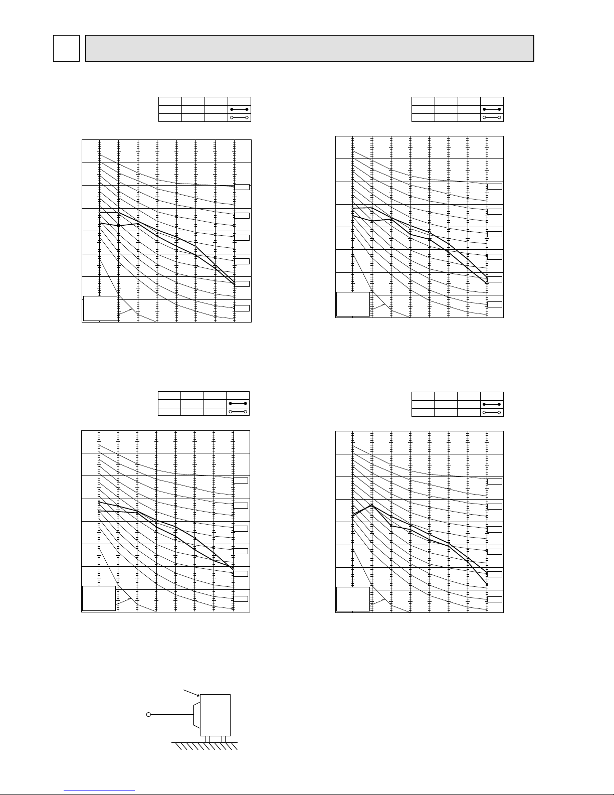
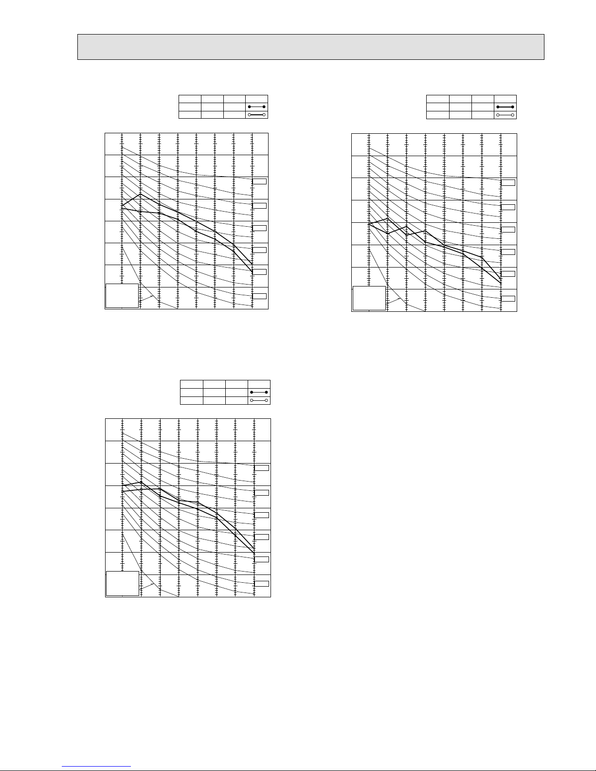
NOISE CRITERIA CURVES
4
90
80
70
60
50
40
30
20
10
63 125 250 500 1000 2000 4000 8000
APPROXIMATE
THRESHOLD OF
HEARING FOR
CONTINUOUS
NOISE
NC-60
NC-50
NC-40
NC-30
NC-20
NC-70
OCTAVE BAND SOUND PRESSURE LEVEL, dB re 0.0002 MICRO BAR
BAND CENTER FREQUENCIES, Hz
CoolingHigh
FUNCTION
FAN SPEED
HeatingHigh
49
SPL(dB(A))51LINE
OUTDOOR UNIT
MICROPHONE
1m
Test conditions
Cooling :Dry-bulb temperature 35.0°C Wet-bulb temperature 24.0°C
Heating :Dry-bulb temperature 7.0°C Wet-bulb temperature 6.0°C
MXZ-4E83VA
90
80
70
60
50
40
30
20
10
63 125 250 500 1000 2000 4000 8000
APPROXIMATE
THRESHOLD OF
HEARING FOR
CONTINUOUS
NOISE
NC-60
NC-50
NC-40
NC-30
NC-20
NC-70
OCTAVE BAND SOUND PRESSURE LEVEL, dB re 0.0002 MICRO BAR
BAND CENTER FREQUENCIES, Hz
CoolingHigh
FUNCTION
FAN SPEED
HeatingHigh
50
SPL(dB(A))53LINE
90
80
70
60
50
40
30
20
10
63 125 250 500 1000 2000 4000 8000
APPROXIMATE
THRESHOLD OF
HEARING FOR
CONTINUOUS
NOISE
NC-60
NC-50
NC-40
NC-30
NC-20
NC-70
OCTAVE BAND SOUND PRESSURE LEVEL, dB re 0.0002 MICRO BAR
BAND CENTER FREQUENCIES, Hz
CoolingHigh
FUNCTION
FAN SPEED
HeatingHigh
50
SPL(dB(A))53LINE
90
80
70
60
50
40
30
20
10
63 125 250 500 1000 2000 4000 8000
APPROXIMATE
THRESHOLD OF
HEARING FOR
CONTINUOUS
NOISE
NC-60
NC-50
NC-40
NC-30
NC-20
NC-70
OCTAVE BAND SOUND PRESSURE LEVEL, dB re 0.0002 MICRO BAR
BAND CENTER FREQUENCIES, Hz
CoolingHigh
FUNCTION
FAN SPEED
HeatingHigh
50
SPL(dB(A))53LINE
MXZ-3E54VA MXZ-3E68VA
MXZ-4E72VA
OBH723D
13
90
80
70
60
50
40
30
20
10
63 125 250 500 1000 2000 4000 8000
APPROXIMATE
THRESHOLD OF
HEARING FOR
CONTINUOUS
NOISE
NC-60
NC-50
NC-40
NC-30
NC-20
NC-70
OCTAVE BAND SOUND PRESSURE LEVEL, dB re 0.0002 MICRO BAR
BAND CENTER FREQUENCIES, Hz
CoolingHigh
FUNCTION
FAN SPEED
HeatingHigh
52
SPL(dB(A))56LINE
MXZ-5E102VA
MXZ-4E83VAHZ
MXZ-2E53VAHZ
90
80
70
60
50
40
30
20
10
63 125 250 500 1000 2000 4000 8000
APPROXIMATE
THRESHOLD OF
HEARING FOR
CONTINUOUS
NOISE
NC-60
NC-50
NC-40
NC-30
NC-20
NC-70
OCTAVE BAND SOUND PRESSURE LEVEL, dB re 0.0002 MICRO BAR
BAND CENTER FREQUENCIES, Hz
CoolingHigh
FUNCTION
FAN SPEED
HeatingHigh
53
SPL(dB(A))57LINE
90
80
70
60
50
40
30
20
10
63 125 250 500 1000 2000 4000 8000
APPROXIMATE
THRESHOLD OF
HEARING FOR
CONTINUOUS
NOISE
NC-60
NC-50
NC-40
NC-30
NC-20
NC-70
OCTAVE BAND SOUND PRESSURE LEVEL, dB re 0.0002 MICRO BAR
BAND CENTER FREQUENCIES, Hz
CoolingHigh
FUNCTION
FAN SPEED
HeatingHigh
45
SPL(dB(A))47LINE
OBH723D
14
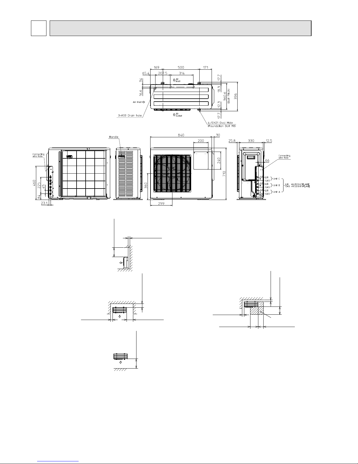
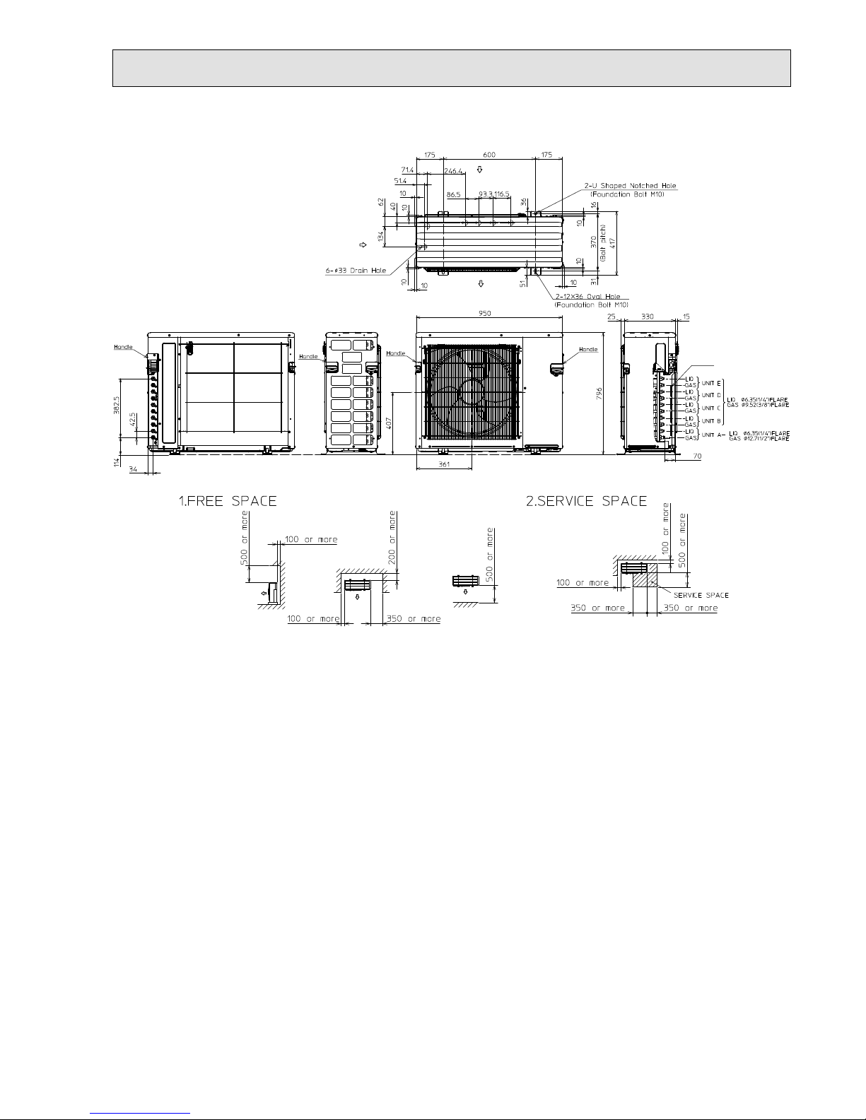
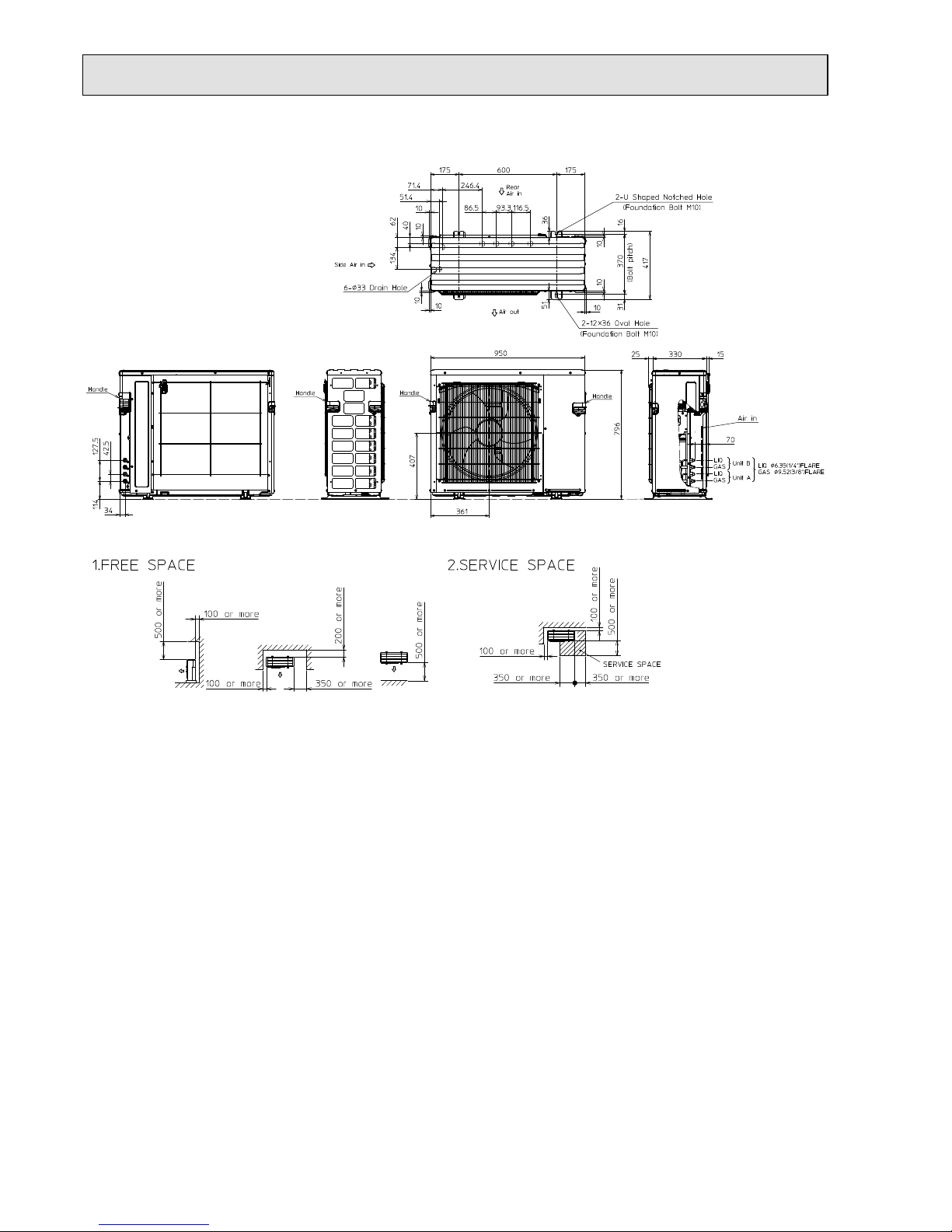
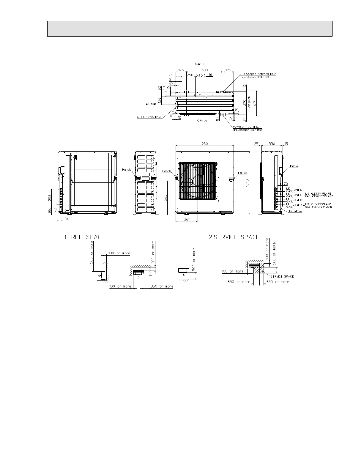
OUTLINES AND DIMENSIONS
5
1.Installation space
Note : Leave front and both sides
free of obstruction.
Note : Leave rear, overhead and
both sides free of obstruction.
500 or more
100 or more
Note : Leave front and overhead
free of obstruction.
100 or more
350 or more
200 or more
500 or more
2.Service space
100 or more
500 or more
350 or more
350 or more
100 or more
Service space
MXZ-3E54VA MXZ-3E68VA
Unit: mm
OBH723D
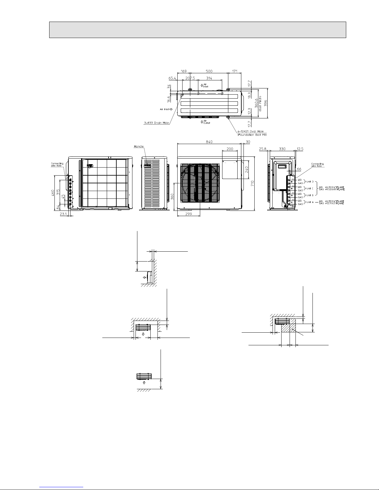
15
1.Installation space
Note : Leave front and both sides
free of obstruction.
Note : Leave rear, overhead and
both sides free of obstruction.
500 or more
100 or more
Note : Leave front and overhead
free of obstruction.
100 or more
350 or more
200 or more
500 or more
2.Service space
100 or more
500 or more
350 or more
350 or more
100 or more
Service space
MXZ-4E72VA
Unit: mm
OBH723D
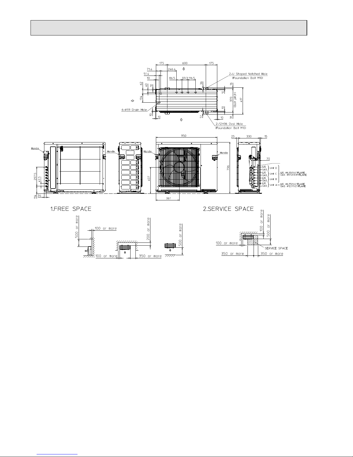
16
MXZ-4E83VA
Unit: mm
Air in
Air in
Air in
Air out
OBH723D
17
MXZ-5E102VA
Unit: mm
Air in
Air in
Air in
Air out
OBH723D
18
Unit: mm
MXZ-2E53VAHZ
OBH723D
19
MXZ-4E83VAHZ
Unit: mm
OBH723D
20
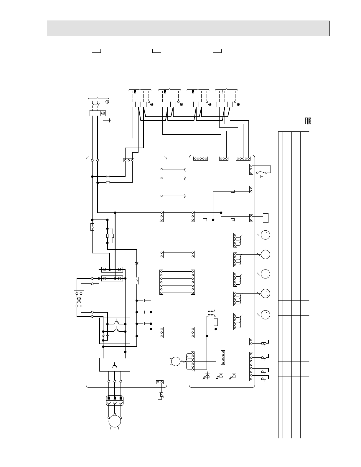
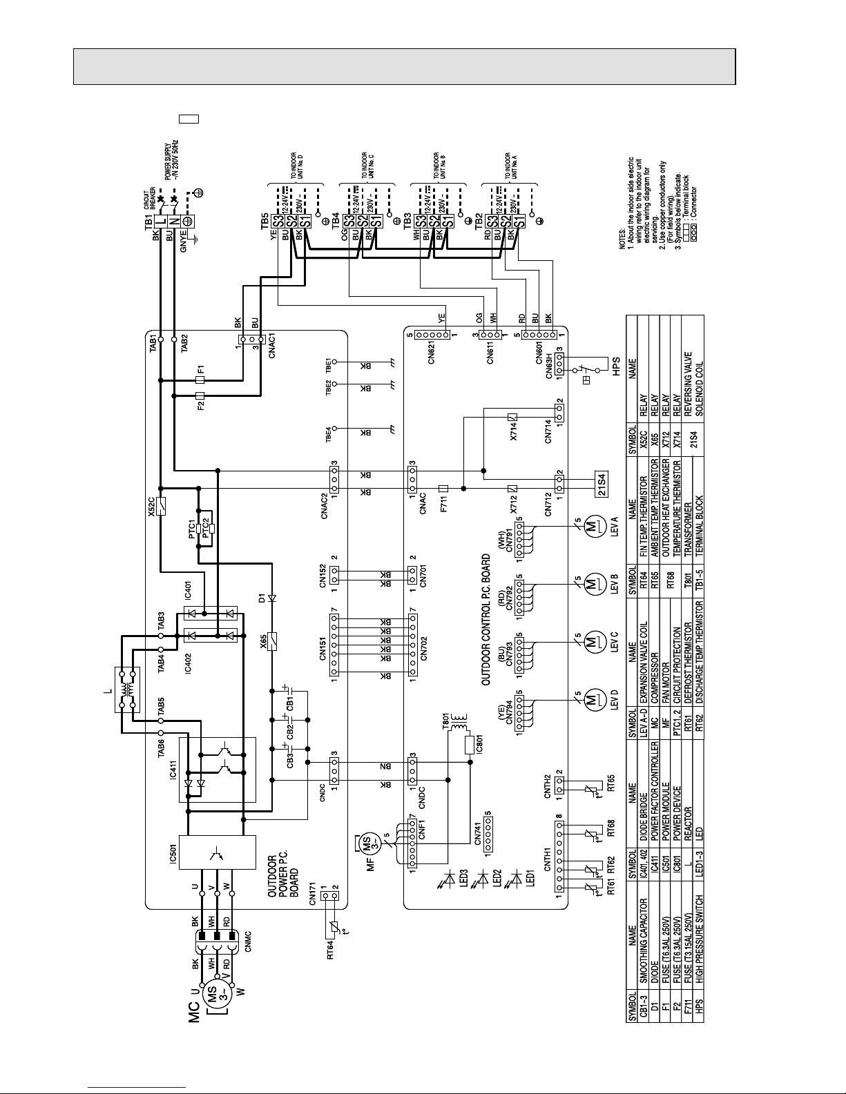
MXZ-3E54VA -E1 MXZ-3E54VA -
ET1
MXZ-3E54VA -
ER1
MXZ-3E68VA -E1 MXZ-3E68VA -
ET1
MXZ-3E68VA -
ER1
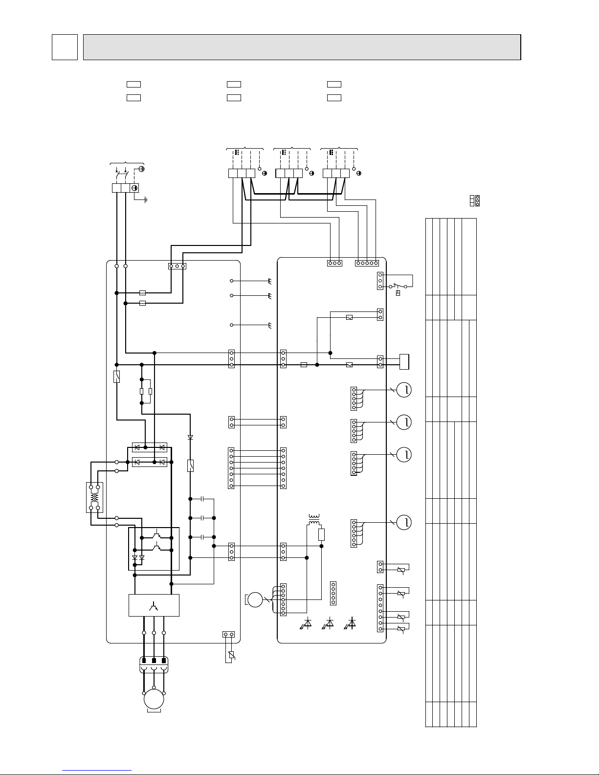
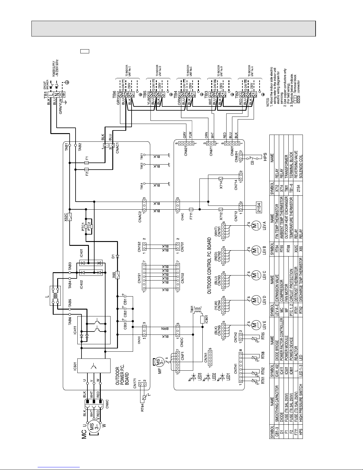
WIRING DIAGRAM
6
t°
21S4
t°°t°t
L
MS
3~
t°
RT64
M
LEV R LEV C LEV ALEV B
RT62
RT61
X714
X712
F711
TO INDOOR
UNIT No.C
TO INDOOR
UNIT No.A
TO INDOOR
UNIT No.B
TB2
TB3
TB4
12-24V
~230V
~230V
12-24V
~230V
12-24V
RT68 RT65
MMM
MS
3~
MF
T801
BLK
WHT
RED
RED
WHT
BLK
U
V
W
MC
CB3
CB2
CB1
BOARD
POWER P.C.
OUTDOOR
OUTDOOR CONTROL P.C. BOARD
F1
F2
TB1
BREAKER
CIRCUIT
POWER SUPPLY
~/N 230V 50Hz
IC801
5
HPS
CN63H
13
1
6
CN797
CN714
1
2
CNAC
CN712
1
2
S1
S2
S3
S1
S2
S3
S1
S2
S3
1
5
CN741
D1
IC401
IC402
2
1
CN171
1
8
CNTH1
2
1
CNTH2
555
CNMC
1
551
1
7
1
CN792 CN791CN793
1
5
5
7
1
CNF1
CN702
1
3
CNDC
U
V
W
1
3
1
CN151
1
7
CNDC
CNAC2
CN701
2
1
1
2
CN152
IC501
IC411
TAB4
TAB6
TAB5
TAB3
X52C
3
5
CN601
1
3
CN611
1
TAB1
TAB2
3
1
CNAC1
3
TBE4 TBE2 TBE1
PTC1
PTC2
X65
L
N
(BLU)
BLK
BLU
RED
BLK
BLU
WHT
BLK
BLU
ORN
BLK
BLK
BRN
BLK
BLK
(RED) (WHT)
(BLU)
BLK
BLK
BLK
BLK
BLK
BLK
BLK
BLK
BLU
RED
BLU
BLK
BLK
BLK
BLK
BLK
BLU
GRN/YLW
WHT
ORN
+++
LEV A~C,R
MC
MF
PTC1,2
RT61
RT62
X52C
X65
X712
X714
21S4
RELAY
RELAY
RELAY
RELAY
REVERSING VALVE
SOLENOID COIL
DEFROST THERMISTOR
FIN TEMP. THERMISTOR
AMBIENT TEMP. THERMISTOR
OUTDOOR HEAT EXCHANGER
TEMPERATURE THERMISTOR
TRANSFORMER
TERMINAL BLOCK
RT64
RT65
RT68
T801
TB1~4
FAN MOTOR
COMPRESSOR
EXPANSION VALVE COIL
DISCHARGE TEMP. THERMISTOR
SMOOTHING CAPACITOR
DIODE
FUSE(T6.3AL250V)
FUSE(T6.3AL250V)
FUSE(T3.15AL250V)
HIGH PRESSURE SWITCH
CB1~3
D1
F1
F2
F711
HPS
CIRCUIT PROTECTION
NOTES:
1.About the indoor side electric
wiring refer to the indoor unit
electric wiring diagram for
servicing.
2.Use copper conductors only
(For field wiring).
3.Symbols below indicate.
:Terminal block
:Connector
SYMBOL
NAME
SYMBOL SYMBOL SYMBOL
NAME NAME NAME
SYMBOL
NAME
DIODE BRIDGE
POWER FACTOR CONTROLLER
POWER MODULE
POWER DEVICE
REACTOR
LED
IC401,402
IC411
IC501
IC801
L
LED1~3
LED3
LED2
LED1
OBH723D
21
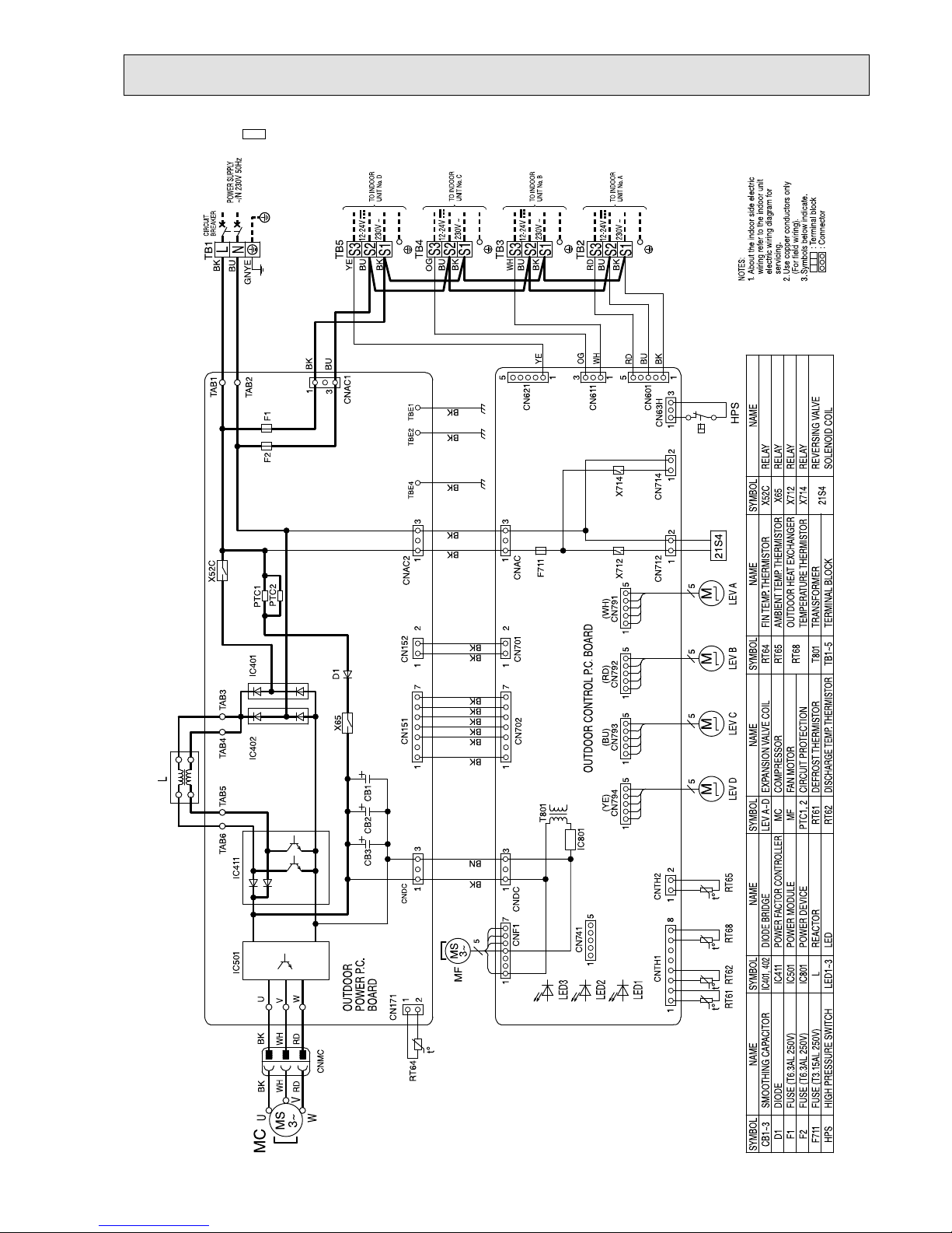
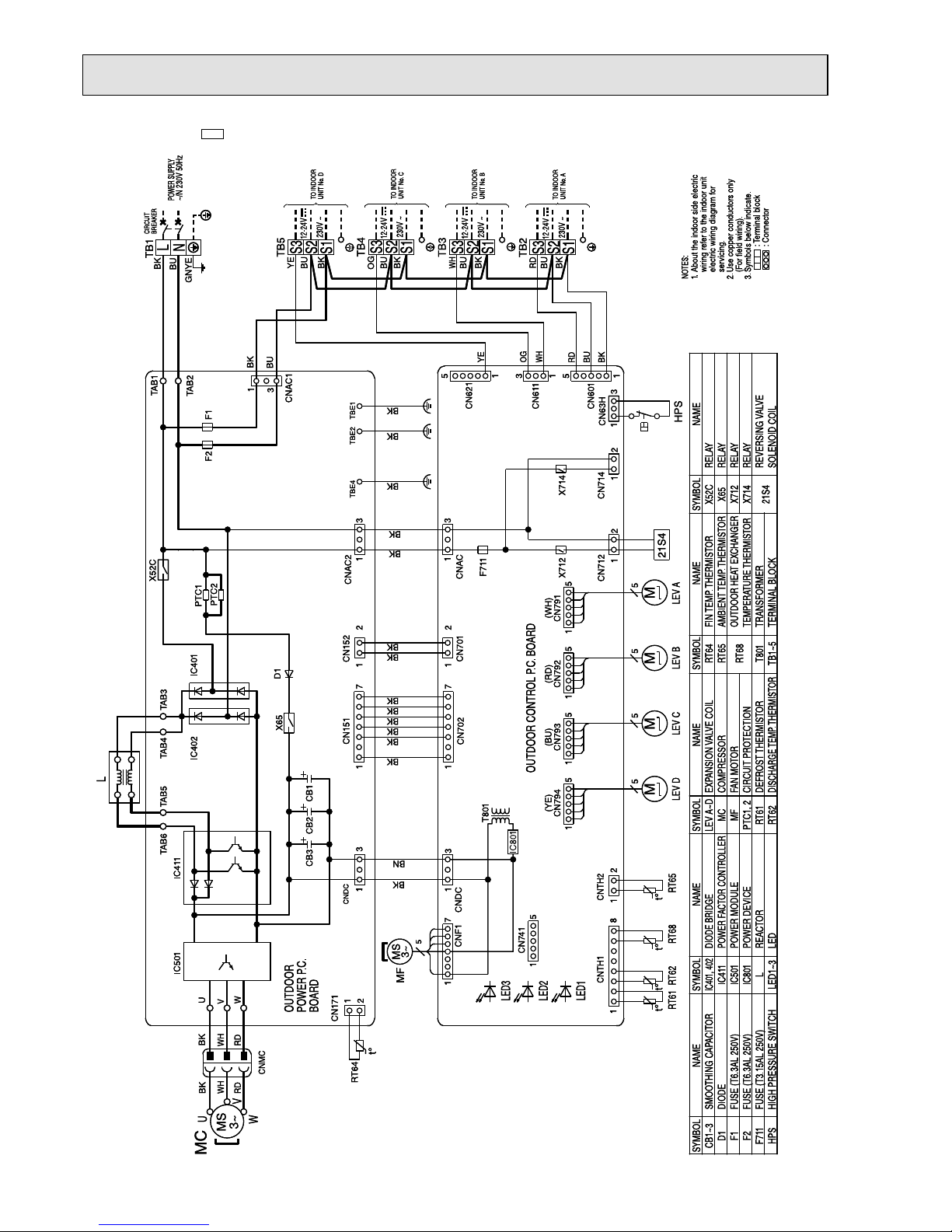
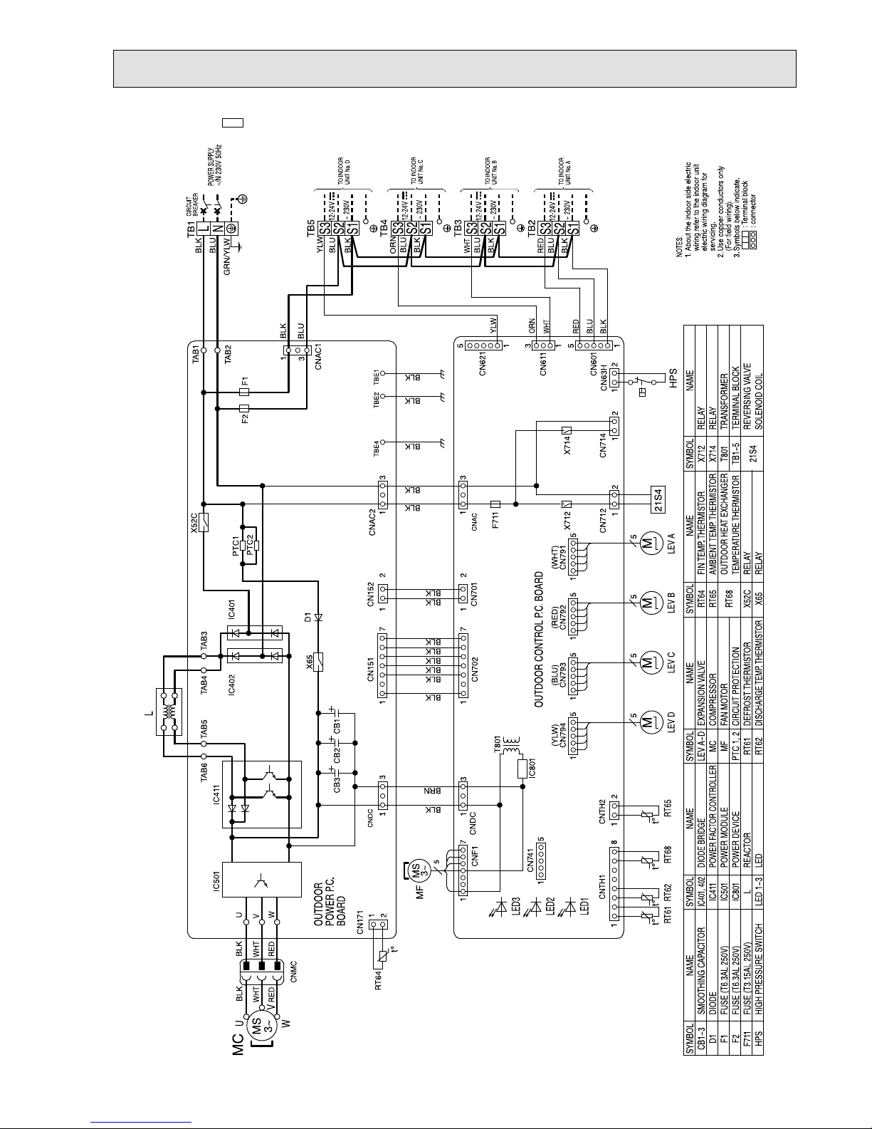
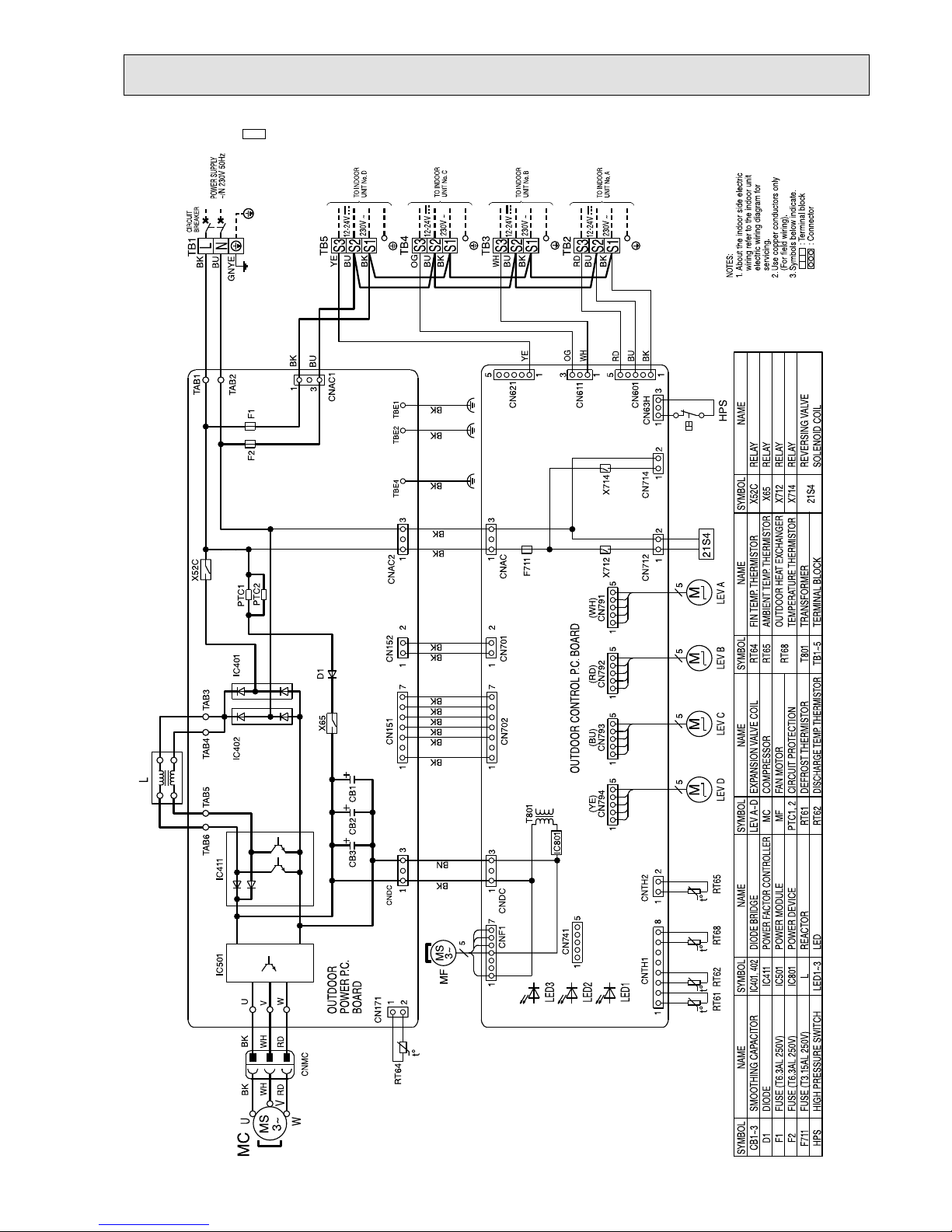
MXZ-4E72VA -E1 MXZ-4E72VA -
ET1
MXZ-4E72VA -
ER1
t°
21S4
t°°t°t
L
MS
3~
RT64
M
LEV R LEV C LEV ALEV B
RT62
RT61
X714
X712
F711
TO INDOOR
UNIT No.C
TO INDOOR
UNIT No.A
TO INDOOR
UNIT No.B
TB2
TB3
TB4
12-24V
~230V
~230V
12-24V
~230V
12-24V
RT68 RT65
MMM
MS
3~
MF
T801
BLK
WHT
RED
RED
WHT
BLK
U
V
W
MC
CB3
CB2
CB1
BOARD
POWER P.C.
OUTDOOR
OUTDOOR CONTROL P.C. BOARD
F1
F2
TB1
BREAKER
CIRCUIT
POWER SUPPLY
~/N 230V 50Hz
LEV D
M
TO INDOOR
UNIT No.D
~230V
12-24V
TB5
IC801
5
HPS
CN63H
13
1
6
CN797
CN714
1
2
CNAC
CN712
1
2
S1
S2
S3
S1
S2
S3
S1
S2
S3
1
5
CN741
D1
IC401
IC402
2
1
CN171
1
8
CNTH1
2
1
CNTH2
555
CNMC
1
551
1
7
1
CN792 CN791CN793
1
5
5
7
1
CNF1
CN702
1
3
CNDC
U
V
W
1
3
1
CN151
1
7
CNDC
CNAC2
CN794
5
1
CN701
2
1
1
2
CN152
IC501
IC411
TAB4
TAB6
TAB5
TAB3
X52C
3
5
CN601
1
3
CN611
1
1
CN621
5
TAB1
TAB2
3
1
CNAC1
3
TBE4 TBE2 TBE1
PTC1
PTC2
X65
L
N
5
S1
S2
S3
(BLU)
BLK
BLU
RED
BLK
BLU
WHT
BLK
BLU
ORN
BLK
BLK
BRN
BLK
BLK
(RED) (WHT)
(BLU)
(YLW)
BLK
BLK
BLK
BLK
BLK
BLK
BLK
BLK
BLU
RED
BLU
BLK
BLK
BLK
BLK
BLK
BLU
GRN/YLW
WHT
ORN
YLW
BLU
BLK
YLW
+++
LEV A~D,R
MC
MF
PTC1,2
RT61
RT62
X52C
X65
X712
X714
21S4
RELAY
RELAY
RELAY
RELAY
REVERSING VALVE
SOLENOID COIL
DEFROST THERMISTOR
FIN TEMP. THERMISTOR
AMBIENT TEMP. THERMISTOR
OUTDOOR HEAT EXCHANGER
TEMPERATURE THERMISTOR
TRANSFORMER
TERMINAL BLOCK
RT64
RT65
RT68
T801
TB1~5
FAN MOTOR
COMPRESSOR
EXPANSION VALVE COIL
DISCHARGE TEMP. THERMISTOR
SMOOTHING CAPACITOR
DIODE
FUSE(T6.3AL250V)
FUSE(T6.3AL250V)
FUSE(T3.15AL250V)
HIGH PRESSURE SWITCH
CB1~3
D1
F1
F2
F711
HPS
CIRCUIT PROTECTION
NOTES:
1.About the indoor side electric
wiring refer to the indoor unit
electric wiring diagram for
servicing.
2.Use copper conductors only
(For field wiring).
3.Symbols below indicate.
:Terminal block
:Connector
SYMBOL
NAME
SYMBOL SYMBOL SYMBOL
NAME NAME NAME
SYMBOL
NAME
DIODE BRIDGE
POWER FACTOR CONTROLLER
POWER MODULE
POWER DEVICE
REACTOR
LED
IC401,402
IC411
IC501
IC801
L
LED1~3
LED3
LED2
LED1
t°
OBH723D

22
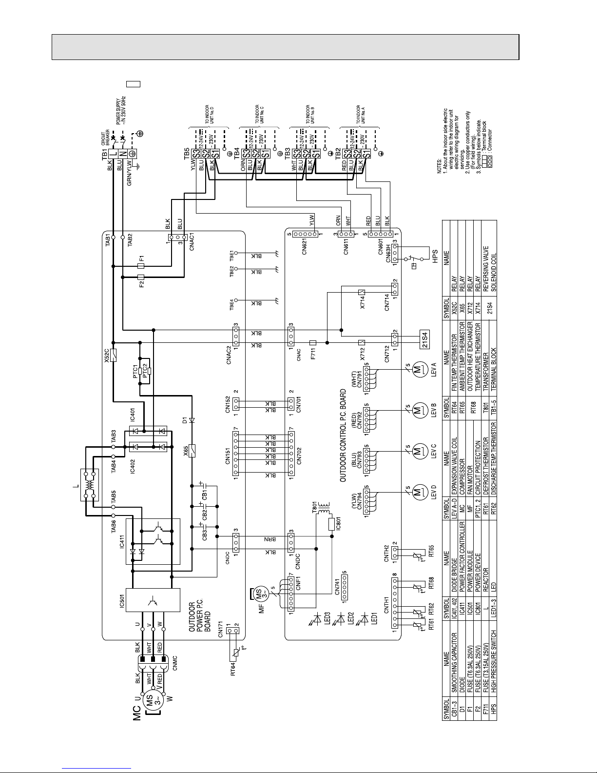
MXZ-4E83VA -
E1
OBH723D
23
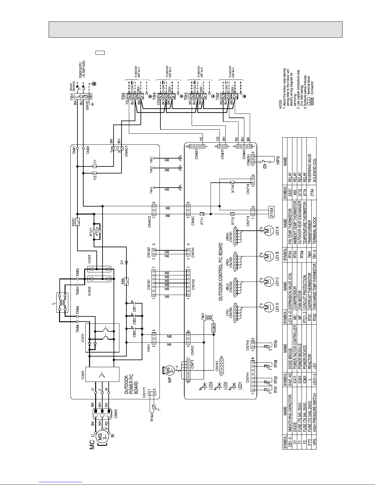
MXZ-4E83VA -
E2
OBH723D
24
MXZ-4E83VA -
E3
OBH723D
25
MXZ-4E83VA -
ET1
OBH723D
26
MXZ-4E83VA -
ET2
OBH723D
27
MXZ-4E83VA -
ET3
OBH723D
28
MXZ-4E83VA -
ER1
OBH723D
29
MXZ-4E83VA -
ER2
OBH723D
30
MXZ-5E102VA -
E1
OBH723D
 Loading...