

Mitsubishi MXZ-2B30VA-E1, MXZ-2B40VA-E1, MXZ-3B54VA-E1, MXZ-3B68VA-E1, MXZ-4B71VA-E1 Service Manual
...
SPLIT-TYPE AIR CONDITIONERS
OUTDOOR UNIT
Revision B:
•
MXZ-2B30VA- E1 and MXZ-2B52VA- E1
have been added.
Please void OBH554
REVISED EDITION-A.
SERVICE MANUAL
Models
MXZ-2B30VA -
MXZ-2B40VA -
MXZ-2B52VA -
MXZ-3B54VA -
MXZ-3B68VA -
E1
E1
E1
E1
E1
MXZ-4B71VA -
MXZ-4B80VA -
MXZ-5B100VA -
HFC
utilized
R410A
Indoor unit service manual
MSZ-FA•VA Series (OB371)
MSZ-FD•VA Series (OBH488)
MSZ-GA•VA Series (OB378, OB388)
MSZ-CB•VA Series (OB441)
MSZ-GC•VA Series (OBH468)
MSZ-GE•VA Series (OBH515)
MSZ-SF•VA Series (OBH555)
MFZ-KA•VA Series (OB409)
MLZ-KA•VA Series (OBH483)
No. OBH554
REVISED EDITION-B
E1
E1
E1
CONTENTS
1. TECHNICAL CHANGES ··································· 2
2. PART NAMES AND FUNCTIONS ····················· 4
3. SPECIFICATION ················································ 5
4. NOISE CRITERIA CURVES ···························· 13
5. OUTLINES AND DIMENSIONS ······················ 15
6. WIRING DIAGRAM ·········································· 19
7. REFRIGERANT SYSTEM DIAGRAM ············· 25
8. PERFORMANCE CURVES ····························· 32
9. ACTUA TOR CONTROL ··································· 59
10. SERVICE FUNCTIONS ···································· 60
11. TROUBLESHOOTING ····································· 64
12. DISASSEMBLY INSTRUCTIONS ···················· 88
MXZ-4B80VA
NOTE:
RoHS compliant products have <G> mark on the spec name plate.
INDOOR UNITS COMBINATION SHEETS
PARTS CATALOG (OBB554)
Revision A :
•
MXZ-2B40VA- E1, MXZ-3B54VA- E1, MXZ-3B68VA- E1 and MXZ-4B71VA- E1
• Power board of
MXZ-4B80VA- E1 and MXZ-5B100VA- E1 has been changed
Revision B :
•
MXZ-2B30VA- E1 and MXZ-2B52VA- E1
have been added.
have been added.
.
1
MXZ-4A80VA -
1. Indoor units combinations have been added (15/20 class).
2. Electronic control P.C. board has been changed.
3. Noise filter P.C. board has been changed.
4. Power board has been changed.
5. LEV coil has been changed.
MXZ-5A100VA -
1. Indoor units combinations have been added (15/20 class).
2. Electronic control P.C. board has been changed.
3. Noise filter P.C. board has been changed.
4. Power board has been changed.
5. LEV coil has been changed.
MXZ-3A54VA -
1. Indoor units combinations have been added (15/20 class).
2. Electronic control P.C. board has been changed.
3. Noise filter P.C. board has been changed.
4. Power board has been changed.
5. LEV coil has been changed.
TECHNICAL CHANGES
E2
E7
MXZ-4B80VA -
E1
MXZ-5B100VA -
MXZ-3B54VA -
E1
E1
E1
MXZ-3B68VA -
1. New model
E1
2

MXZ-4A71VA -
1. Indoor units combinations have been added (15/20 class).
2. Electronic control P.C. board has been changed.
3. Noise filter P.C. board has been changed.
4. Power board has been changed.
5. LEV coil has been changed.
6. Compressor has been changed. (SNB130FGBH1T SNB172FEGH1T)
MXZ-2A30VA -
1. Indoor units combinations have been added (15/20 class).
2. Compressor has been changed. (KNB073FGDH KNB073FGDHC)
3. Inverter P.C. board has been changed.
4. Interface P.C. board has been changed.
5. LEV coil has been changed.
MXZ-2A40VA -
1. Indoor units combinations have been added (15/20 class).
2. Compressor has been changed. (KNB092FEDH KNB092FFDHC)
3. Inverter P.C. board has been changed.
4. Interface P.C. board has been changed.
5. LEV coil has been changed.
E7
E2
E2
MXZ-4B71VA -
MXZ-2B30VA -
MXZ-2B40VA -
E1
E1
E1
MXZ-2A52VA -
1. Indoor units combinations have been added (15/20/42 class).
2. Compressor has been changed. (SNB130FKMH SNB130FGBHT)
3. Inverter P.C. board has been changed.
4. Interface P.C. board has been changed.
5. LEV coil has been changed.
E2
MXZ-2B52VA -
E1
3
2
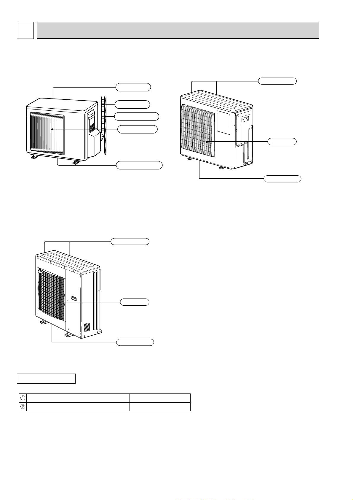
PART NAMES AND FUNCTIONS
MXZ-2B30VA
MXZ-2B40VA
MXZ-2B52VA
MXZ-4B80VA
MXZ-5B100VA
Air inlet
(Back and side)
Piping
Drain hose
Air outlet
Drain outlet
MXZ-3B54VA
MXZ-3B68VA
MXZ-4B71VA
Air inlet
(Back and side)
Air outlet
Drain outlet
ACCESSORIES
Drain socket
Drain cap (MXZ-3B/4B/5B)
Air inlet
(Back and side)
Air outlet
Drain outlet
1
2
4
3
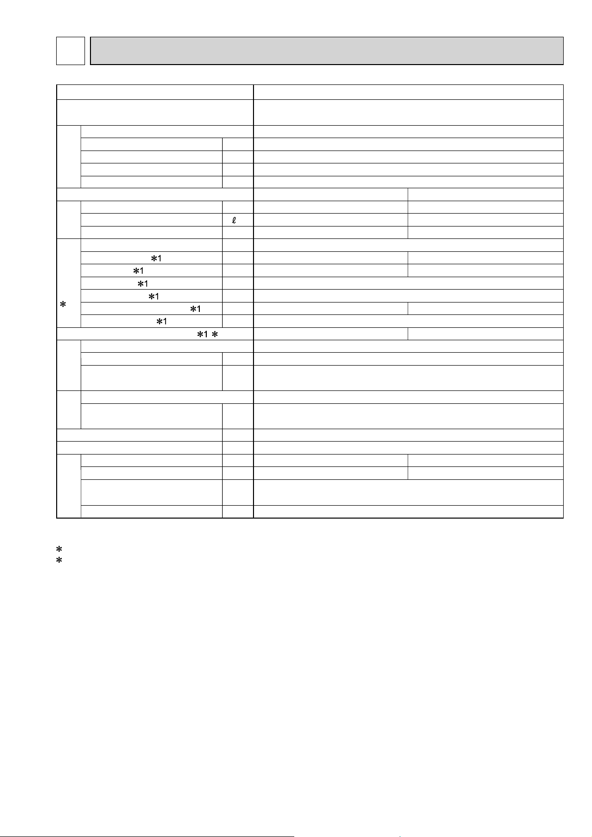
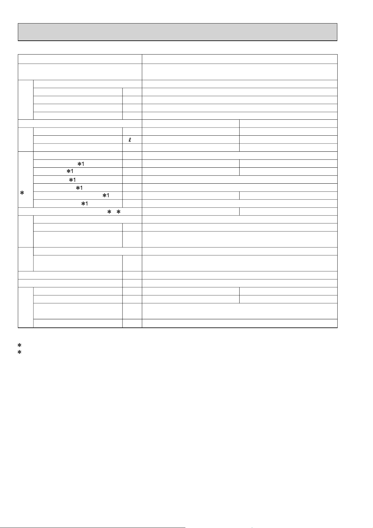
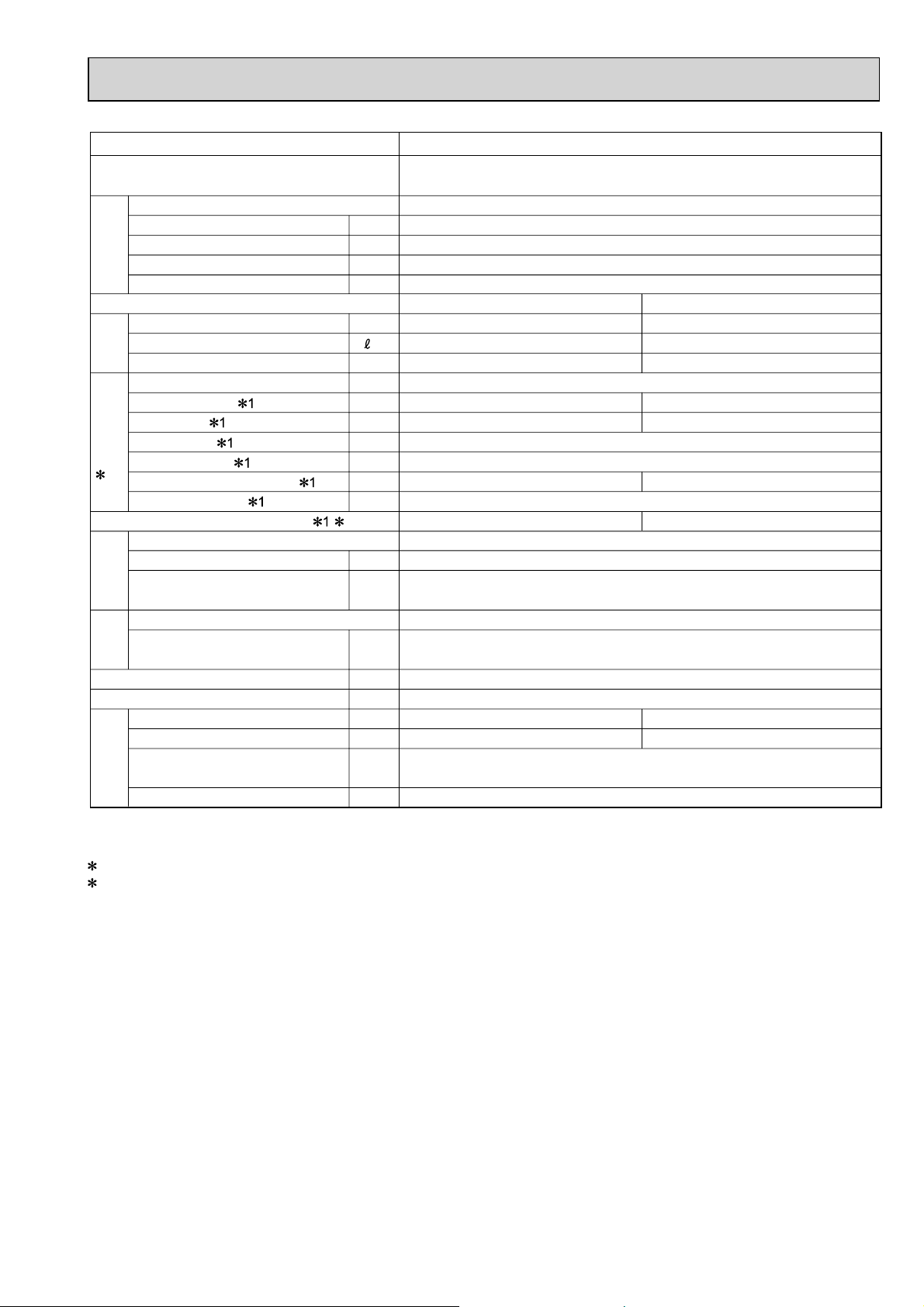
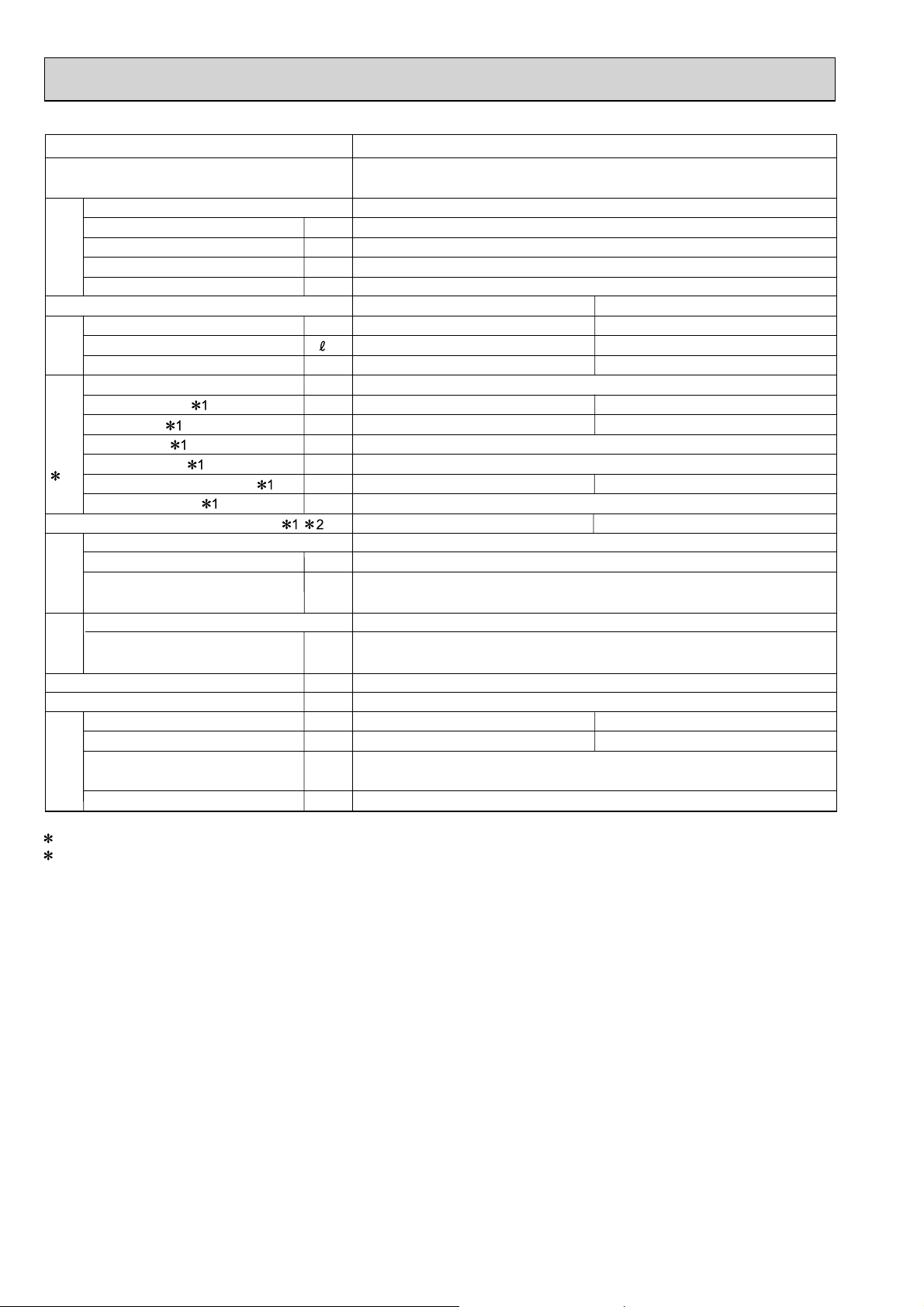
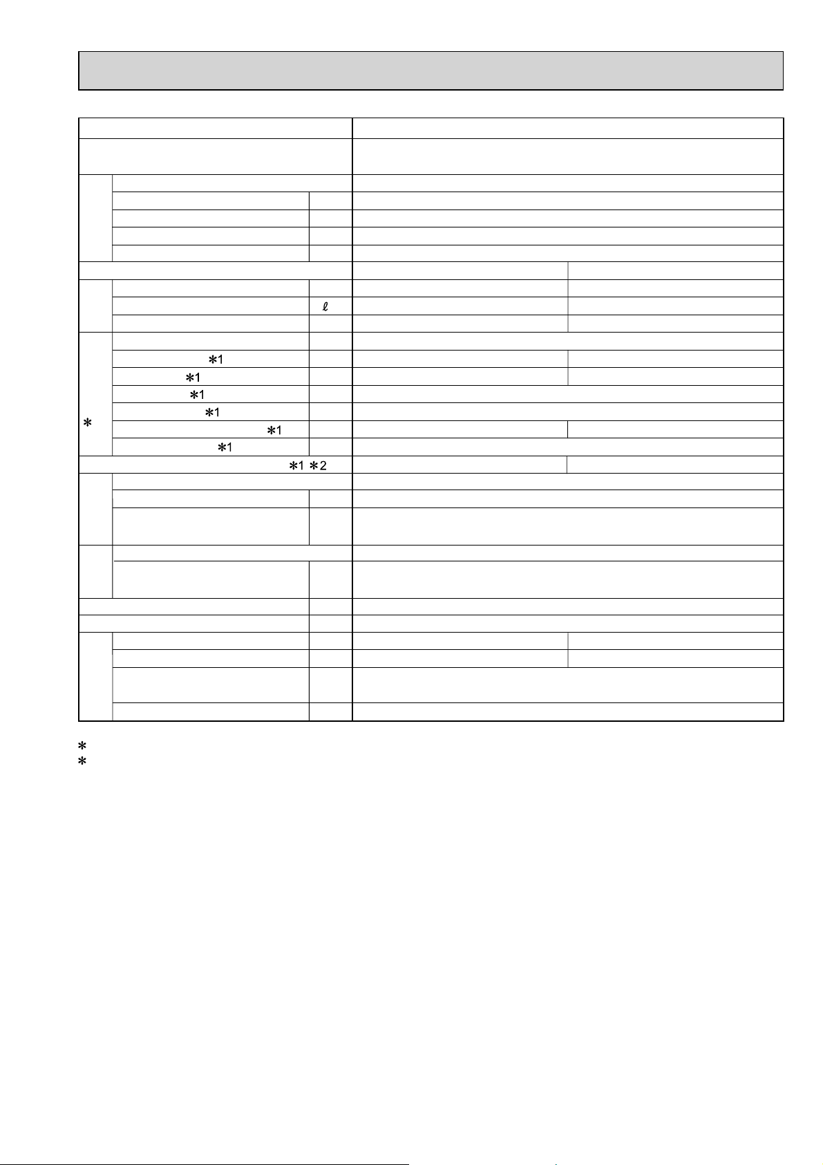
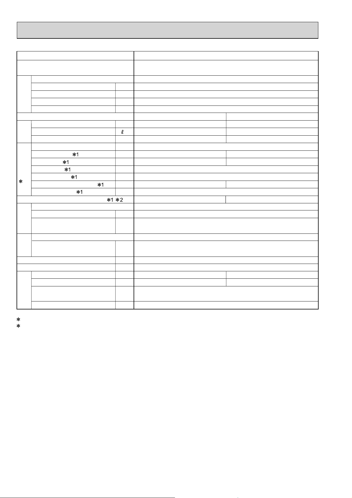
SPECIFICATION
Outdoor model
Outdoor unit power supply
Indoor units number
Piping total length
Connecting pipe length
Height difference (Indoor ~ Outdoor)
Height difference (Indoor ~ Indoor)
Function
Capacity [Rated (Min.-Max.) Hz]
Dehumidification
Outdoor air flow
Capacity System
Breaker capacity
Running current
Power input
Power factor
Starting current
2 Electrical
data
Compressor motor current
Fan motor current
Coefficient of performance(C.O.P) 2
Model
Output
Winding
Compressor
resistance (at 20 °C)
Model
Winding
Fan
motor
resistance (at 20 °C)
Dimensions W x H x D
Weight
Sound level (High/Low)
Fan speed (High/Low)
Refrigerant filling
capacity (R410A)
Special
remarks
Refrigeration oil (Model)
kW
/h
m
mm
dB
rpm
m
m
m
m
W
%
W
Ω
Ω
kg
kg
cc
MXZ-2B30VA
Single phase
230 V, 50 Hz
1 to 2
Max. 20
Max. 15
Refer to 9
Refer to 9
Cooling
3.0 (1.1 - 4.0)
3
/h
A
A
A
A
A
—
2,025
10
2.71
560
90
3.94
2.36
0.35
5.36
KNB073FGDHC
750
U-V 1.70
V-W 1.70 W-U 1.70
RC0J50-CI
BLK-WHT 14.2
WHT-RED 14.2 RED-BLK 14.2
800 x 550 x 285
33
46
880
1.15
320 (NEO22)
Heating
4.0 (1.0 - 4.4)
—
1,855
3.94
815
3.59
4.91
47
810
1 Measured under rated operating frequency.
2 Electrical data is for only outdoor unit.
NOTE: •Test conditions are based on ISO 5151. (Refrigerant piping length (one way): 5 m)
COOLING INDOOR Dry-bulb temperature 27.0°C Wet-bulb temperature 19.0°C
OUTDOOR Dry-bulb temperature 35.0°C Wet-bulb temperature 24.0°C
HEATING INDOOR Dry-bulb temperature 20.0°C
OUTDOOR Dry-bulb temperature 7.0°C Wet-bulb temperature 6.0°C
5
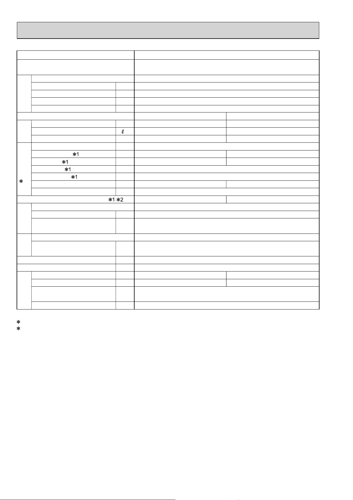
Outdoor model
Outdoor unit power supply
Indoor units number
Piping total length
Connecting pipe length
Height difference (Indoor ~ Outdoor)
Height difference (Indoor ~ Indoor)
Function
Capacity [Rated (Min.-Max.) Hz]
Dehumidification
Outdoor air flow
Capacity System
Breaker capacity
Running current
Power input
Power factor
Starting current
2 Electrical
data
Compressor motor current
Fan motor current
Coefficient of performance(C.O.P) 1 2
Model
Output
Winding
Compressor
resistance (at 20 °C)
Model
Winding
Fan
motor
resistance (at 20 °C)
Dimensions W x H x D
Weight
Sound level
Fan speed
Refrigerant filling
capacity (R410A)
Special
remarks
Refrigeration oil (Model)
kW
/h
m
mm
dB
rpm
m
m
m
m
W
%
W
Ω
Ω
kg
kg
cc
MXZ-2B40VA
Single phase
230 V, 50 Hz
1 to 2
Max. 30
Max. 20
Refer to 9
Refer to 9
Cooling
4.0 (1.1 - 4.5)
—
3
/h
A
A
1,750
15
4.00
875
Heating
4.5 (1.0 - 5.0)
—
1,595
3.98
870
95
A
A
3.65
A
4.57
4.00
3.60
0.35
5.17
KNB092FFDHC
1,100
U-V 1.70
V-W 1.70 W-U 1.70
RC0J50-CI
BLK-WHT 14.2
WHT-RED 14.2 RED-BLK 14.2
800 x 550 x 285
35
47
840
48
770
1.3
320 (NEO22)
1 Measured under rated operating frequency.
2 Electrical data is for only outdoor unit.
NOTE: •Test conditions are based on ISO 5151. (Refrigerant piping length (one way): 5 m)
COOLING INDOOR Dry-bulb temperature 27.0°C Wet-bulb temperature 19.0°C
OUTDOOR Dry-bulb temperature 35.0°C Wet-bulb temperature 24.0°C
HEATING INDOOR Dry-bulb temperature 20.0°C
OUTDOOR Dry-bulb temperature 7.0°C Wet-bulb temperature 6.0°C
6
Outdoor model
Outdoor unit power supply
Indoor units number
Piping total length
Connecting pipe length
Height difference (Indoor ~ Outdoor)
Height difference (Indoor ~ Indoor)
Function
Capacity [Rated (Min.-Max.) Hz]
Dehumidification
Outdoor air flow
Capacity System
Breaker capacity
Running current
Power input
Power factor
Starting current
2 Electrical
data
Compressor motor current
Fan motor current
Coefficient of performance(C.O.P) 2
Model
Output
Winding
Compressor
resistance (at 20 °C)
Model
Winding
Fan
motor
resistance (at 20 °C)
Dimensions W x H x D
Weight
Sound level (High/Low)
Fan speed (High/Low)
Refrigerant filling
capacity (R410A)
Special
remarks
Refrigeration oil (Model)
kW
/h
m
mm
dB
rpm
m
m
m
m
W
%
W
Ω
Ω
kg
kg
cc
MXZ-2B52VA
Single phase
230 V, 50 Hz
1 to 2
Max. 30
Max. 20
Refer to 9
Refer to 9
Cooling
5.2 (1.1 - 6.0)
—
3
/h
A
A
1,975
15
5.83
1,300
Heating
6.4 (1.0 - 7.0)
—
2,000
7.22
1,610
97
A
A
5.48
A
4.00
7.22
6.87
0.35
3.98
SNB130FGBHT
1,400
U-V 0.98
V-W 0.98 W-U 0.98
RC0J50-CI
BLK-WHT 14.2
WHT-RED 14.2 RED-BLK 14.2
800 x 550 x 285
38
49
900
50
910
1.3
450 (NEO22)
1 Measured under rated operating frequency.
2 Electrical data is for only outdoor unit.
NOTE: •Test conditions are based on ISO 5151. (Refrigerant piping length (one way): 5 m)
COOLING INDOOR Dry-bulb temperature 27.0°C Wet-bulb temperature 19.0°C
OUTDOOR Dry-bulb temperature 35.0°C Wet-bulb temperature 24.0°C
HEATING INDOOR Dry-bulb temperature 20.0°C
OUTDOOR Dry-bulb temperature 7.0°C Wet-bulb temperature 6.0°C
7
Outdoor model
Outdoor unit power supply
Indoor units number
Piping total length
Connecting pipe length
Height difference (Indoor ~ Outdoor)
Height difference (Indoor ~ Indoor)
Function
Capacity [Rated (Min.-Max.) Hz]
Dehumidification
Outdoor air flow
Capacity System
Breaker capacity
Running current
Power input
Power factor
Starting current
2 Electrical
data
Compressor motor current
Fan motor current
Coefficient of performance(C.O.P)
Model
Output
Winding
Compressor
resistance (at 20 °C)
Model
Winding
Fan
motor
resistance (at 20°C)
Dimensions W x H x D
Weight
Sound level
Fan speed
Refrigerant filling
Special
remarks
capacity (R410A)
Refrigeration oil (Model)
kW
/h
m
mm
rpm
m
m
m
m
3
A
A
W
%
A
A
A
W
Ω
Ω
kg
dB
kg
cc
/h
MXZ-3B54VA
Single phase
230 V, 50 Hz
1 to 3
Max. 50
Max. 25
Refer to 7 REFRIGERANT SYSTEM DIAGRAM.
Refer to 7 REFRIGERANT SYSTEM DIAGRAM.
Cooling
5.4 (2.9-6.8)
—
2,525
Heating
7.0 (2.6-9.0)
—
2,580
25
5.23
1,190
6.43
1,465
99
6.43
5.03
6.23
0.2
4.23
5.04
SNB130FGBH1T
1,400
U-V 0.98
V-W 0.98 W-U 0.98
RC0J60-AA
BLK-WHT 15.2
WHT-RED 15.2 RED-BLK 15.2
840 x 710 x 330
57
47
650
51
660
2.7
700(NEO22)
1 Measured under rated operating frequency.
2 Electrical data is for only outdoor unit.
NOTE: •Test conditions are based on ISO 5151. (Refrigerant piping length (one way): 5 m)
COOLING INDOOR Dry-bulb temperature 27.0°C Wet-bulb temperature 19.0°C
OUTDOOR Dry-bulb temperature 35.0°C Wet-bulb temperature 24.0°C
HEATING INDOOR Dry-bulb temperature 20.0°C
OUTDOOR Dry-bulb temperature 7.0°C Wet-bulb temperature 6.0°C
8
Outdoor model
Outdoor unit power supply
Indoor units number
Piping total length
Connecting pipe length
Height difference (Indoor ~ Outdoor)
Height difference (Indoor ~ Indoor)
Function
Capacity [Rated (Min.-Max.) Hz]
Dehumidification
Outdoor air flow
Capacity System
Breaker capacity
Running current
Power input
Power factor
Starting current
2 Electrical
data
Compressor motor current
Fan motor current
Coefficient of performance(C.O.P)
Model
Output
Winding
Compressor
resistance (at 20 °C)
Model
Winding
Fan
motor
resistance (at 20°C)
Dimensions W x H x D
Weight
Sound level
Fan speed
Refrigerant filling
Special
remarks
capacity (R410A)
Refrigeration oil (Model)
kW
/h
m
mm
dB
rpm
m
m
m
m
W
%
W
Ω
Ω
kg
kg
cc
MXZ-3B68VA
Single phase
230 V, 50 Hz
1 to 4
Max. 50
Max. 25
Refer to 7 REFRIGERANT SYSTEM DIAGRAM.
Refer to 7 REFRIGERANT SYSTEM DIAGRAM.
Cooling
6.8 (3.7-8.4)
—
3
/h
A
A
2,525
25
7.80
1,775
Heating
8.6 (3.4-10.6)
—
2,580
9.00
2,050
99
A
A
7.60
A
3.83
9.00
8.80
0.2
4.20
SNB172FEGH1T
1,800
U-V 0.72
V-W 0.72 W-U 0.72
RC0J60-AA
BLK-WHT 15.2
WHT-RED 15.2 RED-BLK 15.2
840 x 710 x 330
57
48
650
52
660
2.7
700(NEO22)
1 Measured under rated operating frequency.
2 Electrical data is for only outdoor unit.
NOTE: •Test conditions are based on ISO 5151. (Refrigerant piping length (one way): 5 m)
COOLING INDOOR Dry-bulb temperature 27.0°C Wet-bulb temperature 19.0°C
OUTDOOR Dry-bulb temperature 35.0°C Wet-bulb temperature 24.0°C
HEATING INDOOR Dry-bulb temperature 20.0°C
OUTDOOR Dry-bulb temperature 7.0°C Wet-bulb temperature 6.0°C
9
Outdoor model
Outdoor unit power supply
Indoor units number
Piping total length
Connecting pipe length
Height difference (Indoor ~ Outdoor)
Height difference (Indoor ~ Indoor)
Function
Capacity [Rated (Min.-Max.) Hz]
Dehumidification
Outdoor air flow
Capacity System
Breaker capacity
Running current
Power input
Power factor
Starting current
2 Electrical
data
Compressor motor current
Fan motor current
Coefficient of performance(C.O.P)
Model
Output
Winding
Compressor
resistance (at 20 °C)
Model
Winding
Fan
motor
resistance (at 20°C)
Dimensions W x H x D
Weight
Sound level
Fan speed
Refrigerant filling
Special
remarks
capacity (R410A)
Refrigeration oil (Model)
kW
/h
m
mm
dB
rpm
m
m
m
m
W
%
W
Ω
Ω
kg
kg
cc
MXZ-4B71VA
Single phase
230 V, 50 Hz
1 to 4
Max. 60
Max. 25
Refer to 7 REFRIGERANT SYSTEM DIAGRAM.
Refer to 7 REFRIGERANT SYSTEM DIAGRAM.
Cooling
7.1 (3.7-8.8)
—
3
/h
A
A
2,525
25
7.38
1,680
Heating
8.6 (3.4-10.7)
—
2,580
7.49
1,705
99
A
A
7.18
A
4.54
7.49
7.29
0.2
4.78
SNB172FEGH1T
2,000
U-V 0.72
V-W 0.72 W-U 0.72
RC0J60-AA
BLK-WHT 15.2
WHT-RED 15.2 RED-BLK 15.2
840 x 710 x 330
58
48
650
52
660
2.7
700(NEO22)
1 Measured under rated operating frequency.
2 Electrical data is for only outdoor unit.
NOTE: •Test conditions are based on ISO 5151. (Refrigerant piping length (one way): 5 m)
COOLING INDOOR Dry-bulb temperature 27.0°C Wet-bulb temperature 19.0°C
OUTDOOR Dry-bulb temperature 35.0°C Wet-bulb temperature 24.0°C
HEATING INDOOR Dry-bulb temperature 20.0°C
OUTDOOR Dry-bulb temperature 7.0°C Wet-bulb temperature 6.0°C
10

Outdoor model
Outdoor unit power supply
Indoor units number
Piping total length
Connecting pipe length
Height difference (Indoor ~ Outdoor)
Height difference (Indoor ~ Indoor)
Function
Capacity [Rated (Min.-Max.) Hz]
Dehumidification
Outdoor air flow
Capacity System
Breaker capacity
Running current
Power input
Power factor
Starting current
2 Electrical
data
Compressor motor current
Fan motor current
Coefficient of performance(C.O.P)
Model
Output
Winding
Compressor
resistance (at 20 °C)
Model
Winding
Fan
motor
resistance (at 20°C)
Dimensions W x H x D
Weight
Sound level
Fan speed
Refrigerant filling
Special
remarks
capacity (R410A)
Refrigeration oil (Model)
kW
/h
m
mm
dB
rpm
m
m
m
m
W
%
W
Ω
Ω
kg
kg
cc
MXZ-4B80VA
Single phase
230 V, 50 Hz
1 to 4
Max. 70
Max. 25
Refer to 7 REFRIGERANT SYSTEM DIAGRAM.
Refer to 7 REFRIGERANT SYSTEM DIAGRAM.
Cooling
8.0 (3.7-9.2)
—
3
/h
A
A
2,530
25
8.59
1,955
Heating
9.4 (3.4-11.6)
—
2,630
8.48
1,930
99
A
A
8.39
A
4.09
8.59
8.28
0.2
4.87
TNB220FMCH
2,100
U-V 1.41
V-W 1.41 W-U 1.41
PM8H60-UA
BLK-WHT 15.2
WHT-RED 15.2 RED-BLK 15.2
900 x 900 x 320
67
46
560
48
590
3.5
870(NEO22)
1 Measured under rated operating frequency.
2 Electrical data is for only outdoor unit.
NOTE: •Test conditions are based on ISO 5151. (Refrigerant piping length (one way): 5 m)
COOLING INDOOR Dry-bulb temperature 27.0°C Wet-bulb temperature 19.0°C
OUTDOOR Dry-bulb temperature 35.0°C Wet-bulb temperature 24.0°C
HEATING INDOOR Dry-bulb temperature 20.0°C
OUTDOOR Dry-bulb temperature 7.0°C Wet-bulb temperature 6.0°C
11
Outdoor model
Outdoor unit power supply
Indoor units number
Piping total length
Connecting pipe length
Height difference (Indoor ~ Outdoor)
Height difference (Indoor ~ Indoor)
Function
Capacity [Rated (Min.-Max.) Hz
Dehumidification
Outdoor air flow
Capacity System
Breaker capacity
Running current
Power input
Power factor
Starting current
2 Electrical
data
Compressor motor current
Fan motor current
Coefficient of performance(C.O.P)
Model
Output
Winding
Compressor
resistance(at 20 °C)
Model
Winding
Fan
motor
resistance(at 20 °C)
Dimensions W x H x D
Weight
Sound level
Fan speed
Refrigerant filling
capacity(R410A)
Special
remarks
Refrigeration oil (Model)
kW
/h
m
mm
dB
rpm
m
m
m
m
W
%
W
Ω
Ω
kg
kg
cc
MXZ-5B100VA
Single phase
230 V, 50 Hz
1 to 5
Max. 80
Max. 25
Refer to 7 REFRIGERANT SYSTEM DIAGRAM.
Refer to 7 REFRIGERANT SYSTEM DIAGRAM.
Cooling
10.0 (3.9 - 11.0)
—
3
/h
A
A
3,396
25
12.30
2,880
Heating
12.0 (4.1 - 14.0)
—
3,558
12.45
2,835
99
A
A
12.10
A
3.57
12.45
12.25
0.2
4.23
TNB220FMCH
2,700
U-V 1.41
V-W 1.41 W-U 1.41
PM8H60-UA
BLK-WHT 15.2
WHT-RED 15.2 RED-BLK 15.2
900 x 900 x 320
68
51
720
54
750
4.0
870 (NEO22)
1 Measured under rated operating frequency.
2 Electrical data is for only outdoor unit.
NOTE: •Test conditions are based on ISO 5151. (Refrigerant piping length (one way): 5 m)
COOLING INDOOR Dry-bulb temperature 27.0°C Wet-bulb temperature 19.0°C
OUTDOOR Dry-bulb temperature 35.0°C Wet-bulb temperature 24.0°C
HEATING INDOOR Dry-bulb temperature 20.0°C
OUTDOOR Dry-bulb temperature 7.0°C Wet-bulb temperature 6.0°C
12
4
NOISE CRITERIA CURVES
MXZ-2B30VA
FAN SPEED
FUNCTION
CoolingHigh
HeatingHigh
SPL(dB(A))47LINE
46
MXZ-2B40VA
FAN SPEED
FUNCTION
CoolingHigh
HeatingHigh
SPL(dB(A))48LINE
47
90
80
70
60
50
40
30
20
OCTAVE BAND SOUND PRESSURE LEVEL, 0dB = 0.0002 MICRO BAR
10
63 125 250 500 1000 2000 4000 8000
NC-10
BAND CENTER FREQUENCIES, Hz
FUNCTION
MXZ-2B52VA
FAN SPEED
CoolingHigh
HeatingHigh
NC-70
NC-60
NC-50
NC-40
NC-30
NC-20
SPL(dB(A))50LINE
49
90
80
70
60
50
40
30
APPROXIMATE
20
THRESHOLD OF
HEARING FOR
CONTINUOUS
NOISE
OCTAVE BAND SOUND PRESSURE LEVEL, 0dB = 0.0002 MICRO BAR
10
63 125 250 500 1000 2000 4000 8000
BAND CENTER FREQUENCIES, Hz
FAN SPEED
FUNCTION
MXZ-3B54VA
CoolingHigh
HeatingHigh
SPL(dB(A))51LINE
47
NC-70
NC-60
NC-50
NC-40
NC-30
NC-20
90
80
70
60
50
40
30
20
OCTAVE BAND SOUND PRESSURE LEVEL, 0dB = 0.0002 MICRO BAR
10
63 125 250 500 1000 2000 4000 8000
NC-10
BAND CENTER FREQUENCIES, Hz
NC-70
NC-60
NC-50
NC-40
NC-30
NC-20
90
80
70
60
50
40
30
APPROXIMATE
20
THRESHOLD OF
HEARING FOR
CONTINUOUS
OCTAVE BAND SOUND PRESSURE LEVEL, 0dB = 0.0002 MICRO BAR
NOISE
10
63 125 250 500 1000 2000 4000 8000
BAND CENTER FREQUENCIES, Hz
NC-70
NC-60
NC-50
NC-40
NC-30
NC-20
13
MXZ-3B68VA
FAN SPEED
FUNCTION
CoolingHigh
HeatingHigh
SPL(dB(A))52LINE
48
MXZ-4B71VA
FAN SPEED
FUNCTION
CoolingHigh
HeatingHigh
SPL(dB(A))52LINE
48
90
80
70
60
50
40
30
OCTAVE BAND SOUND PRESSURE LEVEL, 0dB = 0.0002 MICRO BAR
20
APPROXIMATE
THRESHOLD OF
HEARING FOR
CONTINUOUS
NOISE
10
63 125 250 500 1000 2000 4000 8000
MXZ-4B80VA
BAND CENTER FREQUENCIES, Hz
FAN SPEED
90
FUNCTION
CoolingHigh
HeatingHigh
SPL(dB(A))48LINE
46
NC-70
NC-60
NC-50
NC-40
NC-30
NC-20
90
80
70
60
50
40
30
OCTAVE BAND SOUND PRESSURE LEVEL, 0dB = 0.0002 MICRO BAR
20
APPROXIMATE
THRESHOLD OF
HEARING FOR
CONTINUOUS
NOISE
10
63 125 250 500 1000 2000 4000 8000
MXZ-5B100VA
BAND CENTER FREQUENCIES, Hz
90
FAN SPEED
FUNCTION
CoolingHigh
HeatingHigh
NC-70
NC-60
NC-50
NC-40
NC-30
NC-20
SPL(dB(A))54LINE
51
80
70
60
50
40
30
OCTAVE BAND SOUND PRESSURE LEVEL, 0dB = 0.0002 MICRO BAR
20
APPROXIMATE
THRESHOLD OF
HEARING FOR
CONTINUOUS
NOISE
10
63 125 250 500 1000 2000 4000 8000
BAND CENTER FREQUENCIES, Hz
OUTDOOR UNIT
1m
MICROPHONE
80
NC-70
NC-60
NC-50
NC-40
NC-30
NC-20
70
60
50
40
30
OCTAVE BAND SOUND PRESSURE LEVEL, 0dB = 0.0002 MICRO BAR
20
APPROXIMATE
THRESHOLD OF
HEARING FOR
CONTINUOUS
NOISE
10
63 125 250 500 1000 2000 4000 8000
BAND CENTER FREQUENCIES, Hz
Test conditions
Cooling :Dry-bulb temperature 35°C Wet-bulb temperature 24°C
Heating :Dry-bulb temperature 7°C Wet-bulb temperature 6°C
NC-70
NC-60
NC-50
NC-40
NC-30
NC-20
14
5
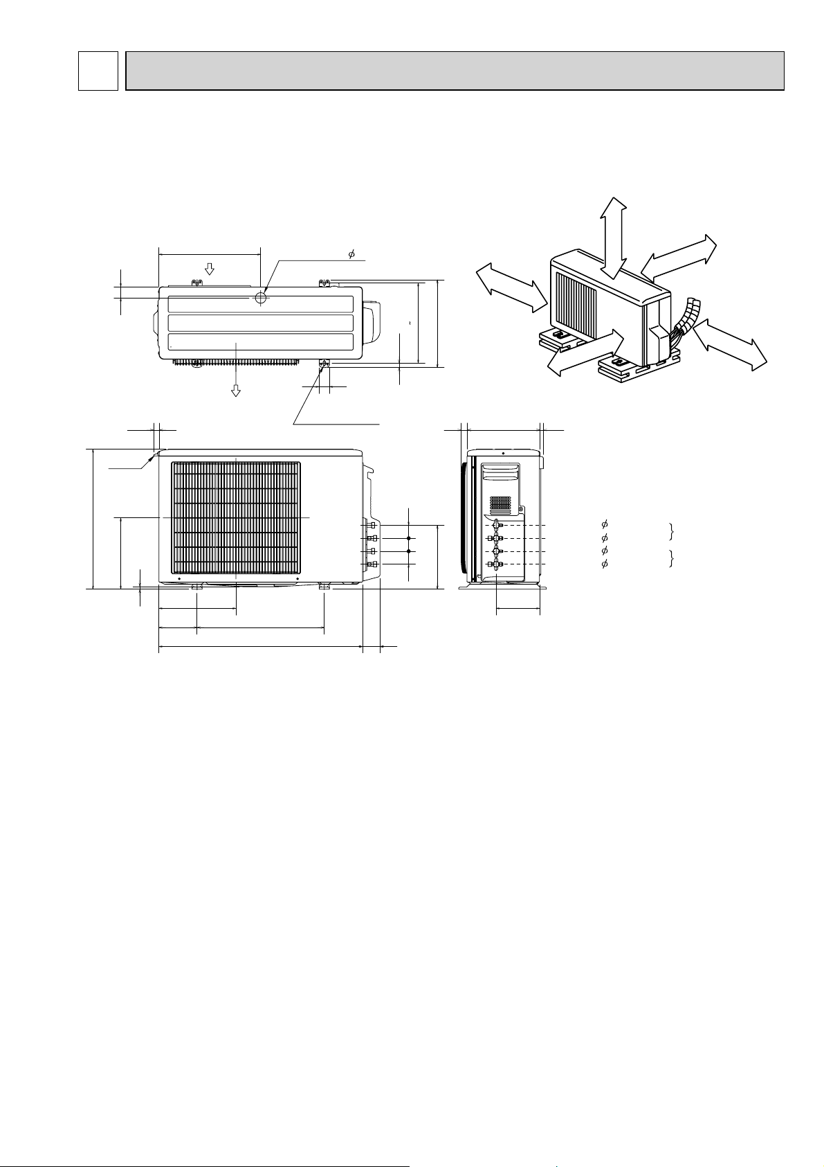
OUTLINES AND DIMENSIONS
MXZ-2B30VA
MXZ-2B40VA
MXZ-2B52VA
550
44
handle
280
22.3
10
400
302.5
Air out
500150
800
Drainage hole 42
40
2-10x21 Oval hole
REQUIRED SPACE
100mm or more
344.5
304 325
17.5
51
51 51
251.1
170.4
69
200mm or more
Open two sides of left,
right, or rear side.
1323 285
Liquid pipe : 6.35(flared)1/4
Gas pipe : 9.52(flared)3/8
Liquid pipe : 6.35(flared)1/4
Gas pipe : 9.52(flared)3/8
Basically open 100mm or more
without any obstruction in front
and on both sides of the unit.
100mm or more
350mm or more
B unit
connection
A unit
connection
15
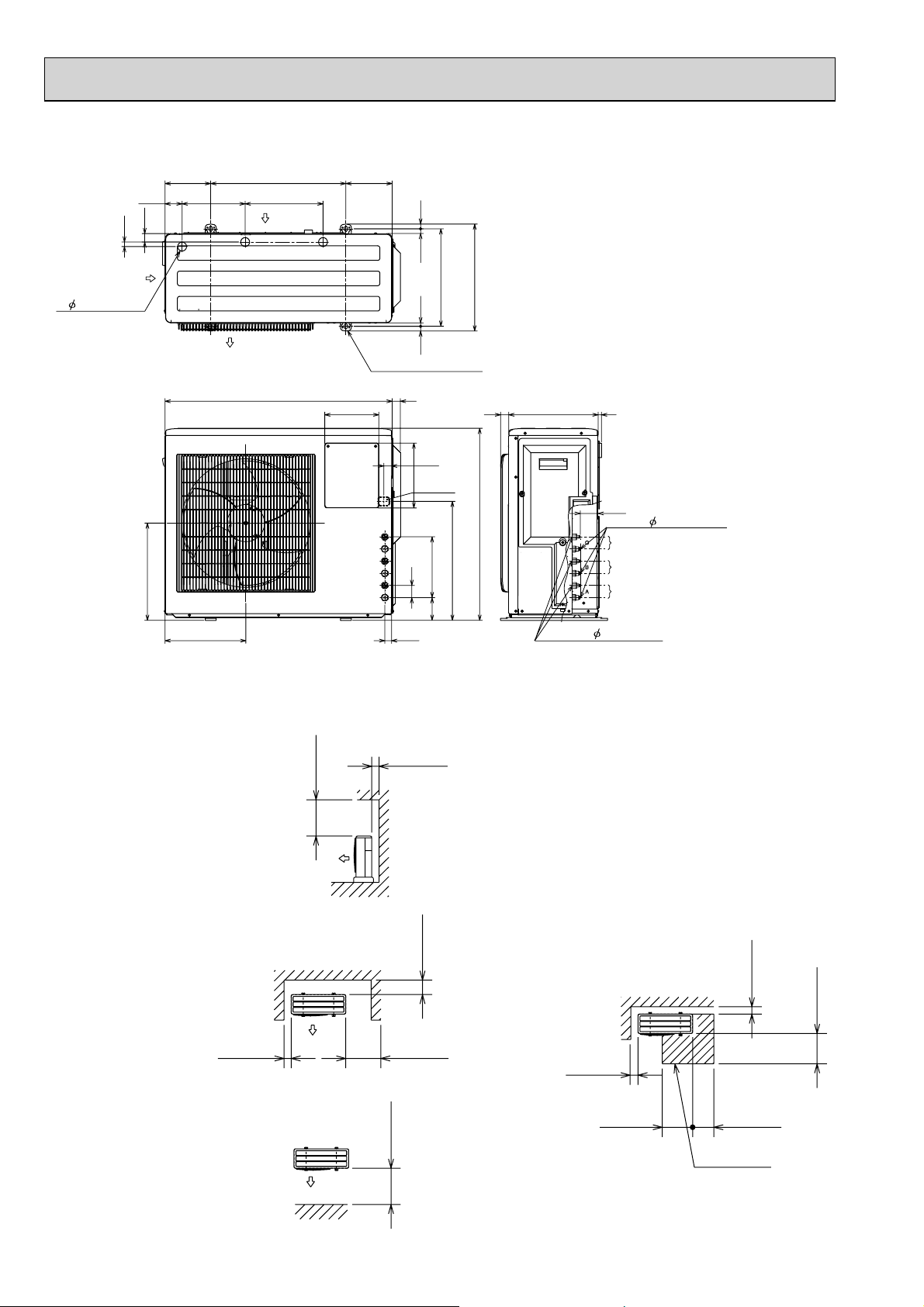
MXZ-3B54VA MXZ-3B68VA
16.8
63.2
31.3
288233.1
Air in
Unit: mm
171500169
17.717.7
Air in
3- 33 Drain hole
360
299
Air out
840
4-10 x 21 Oval hole
(Base bolt M10)
200
13.3 20.3
30
27.1
Indoor and outdoor
connect wiring
240
39 x 27 hole
225
45
84
23.1
360.6
(Bolt Pitch)
440
396
30 330
710
13
66.3
Gas pipe 9.52(flared)3/8
C unit connection
B unit connection
A unit connection
Liquid pipe 6.35(flared)1/4
1.Installation space
Note : Leave front and both sides
free of obstruction.
Note : Leave front and overhead
free of obstruction.
More than
100
Note : Leave rear, overhead and
both sides free of obstruction.
More than
500
More than
100
More than
More than
350
More than
500
200
2.Service space
More than
100
More than
More than
100
More than
350350
Service space
500
More than
16
t
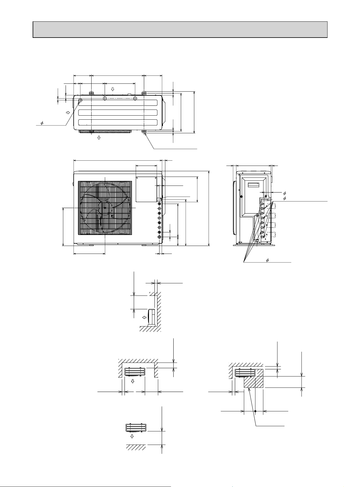
MXZ-4B71VA
Unit: mm
16.8
Air in
3- 33 Drain hole
169
63.2 288233.1
31.3
360
Air in
Air out
840 30
171500
4-10 x 21 Oval hole
(Base bolt M10)
200
17.7
20.313.3
360.6
(Bolt Pitch)
17.7
27.1
Indoor and outdoor
connect wiring
39 x 27 hole
31584
440
45
396
240
710
330 1330
Gas pipe
66.3
9.52(flared)3/8(B,C,D uni
12.7(flared)1/2(A unit)
D unit connection
C unit connection
B unit connection
A unit connection
299
1.Installation space
Note : Leave front and both sides
free of obstruction.
Note : Leave front and overhead
free of obstruction.
More than
100
More than
500
23.1
More than
100
200
More than
More than
350
2.Service space
More than
100
More than
Liquid pipe 6.35(flared)1/4
More than
100
More than
350350
500
More than
Note : Leave rear, overhead and
both sides
free of obstruction.
More than
500
Service space
17
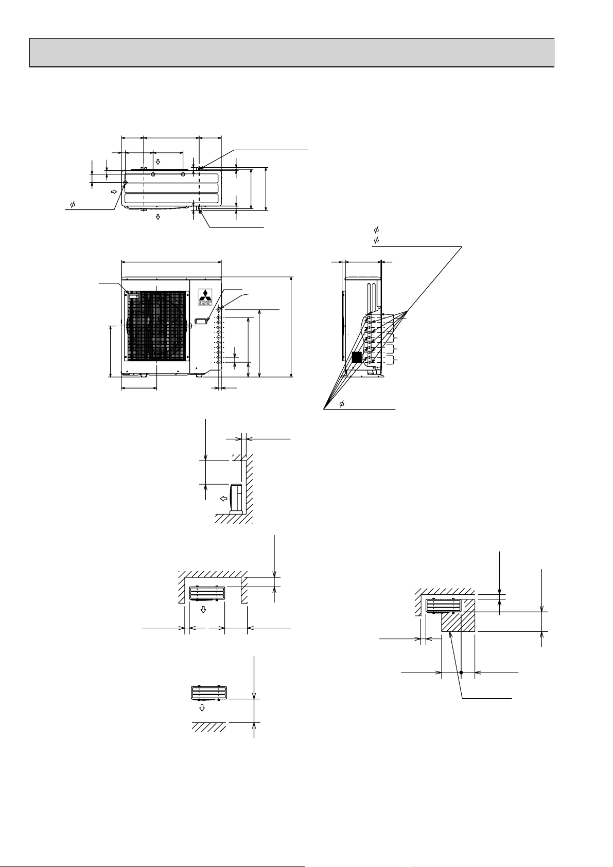
MXZ-4B80VA
74
Air in
3- 33 Drain hole
MXZ-5B100VA
200 200500
35
35
250
270
Air in
Air out
900
27
40
2-12 x 36 Oval hole
(Base bolt M10)
2-U Shaped notched hole
(Base bolt M10)
16
11
355
387
24
(Bolt pitch)
16
Unit: mm
Gas pipe
9.52(flared) 3/8 (B,C,D,E (MXZ-5B100VA) unit)
12.7(flared) 1/2 (A unit)
32030 10
Handle
460
1.Installation space
Note : Leave front and both sides
free of obstruction.
Note : Leave front and overhead
free of obstruction.
317
More than
100
More than
500
Handle
45
23
Indoor and
outdoor
connect
wiring
(35 x 53) hole
597
132 405
More than
100
200
More than
More than
350
900
88
B
A
Liquid pipe
6.35(flared)1/4
2.Service space
More than
100
E unit connection (MXZ-5B100VA)
D unit connection
C unit connection
B unit connection
A unit connection
More than
100
500
More than
Note : Leave rear, overhead and
both sides free of obstruction.
More than
500
18
More than
More than
350350
Service space
6
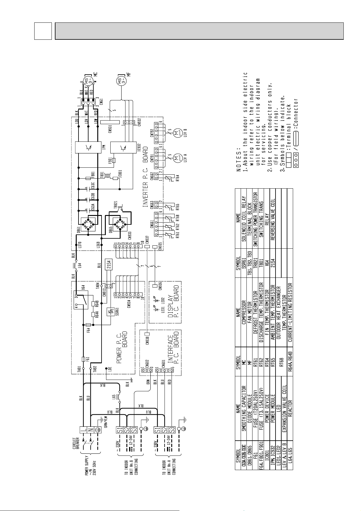
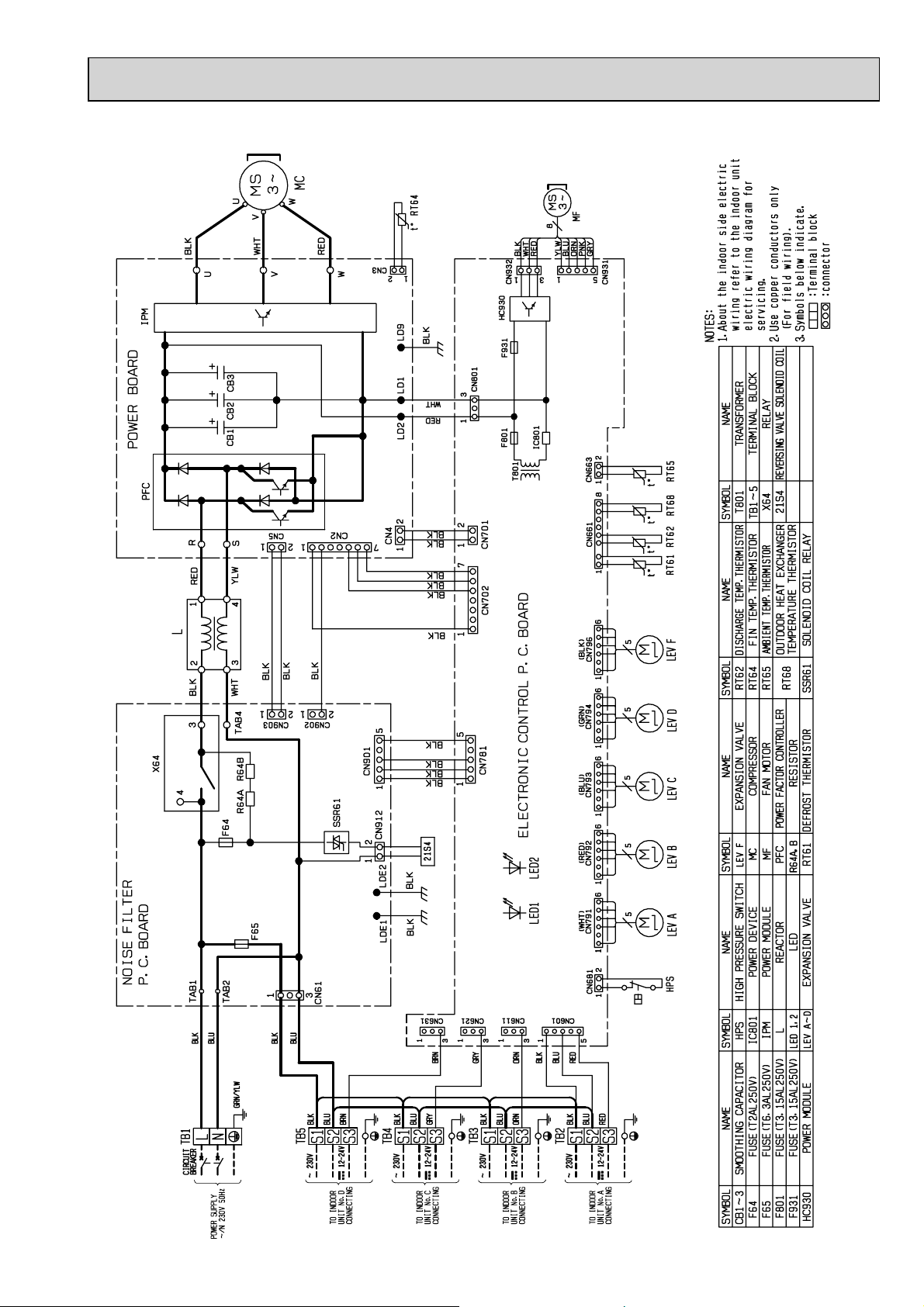
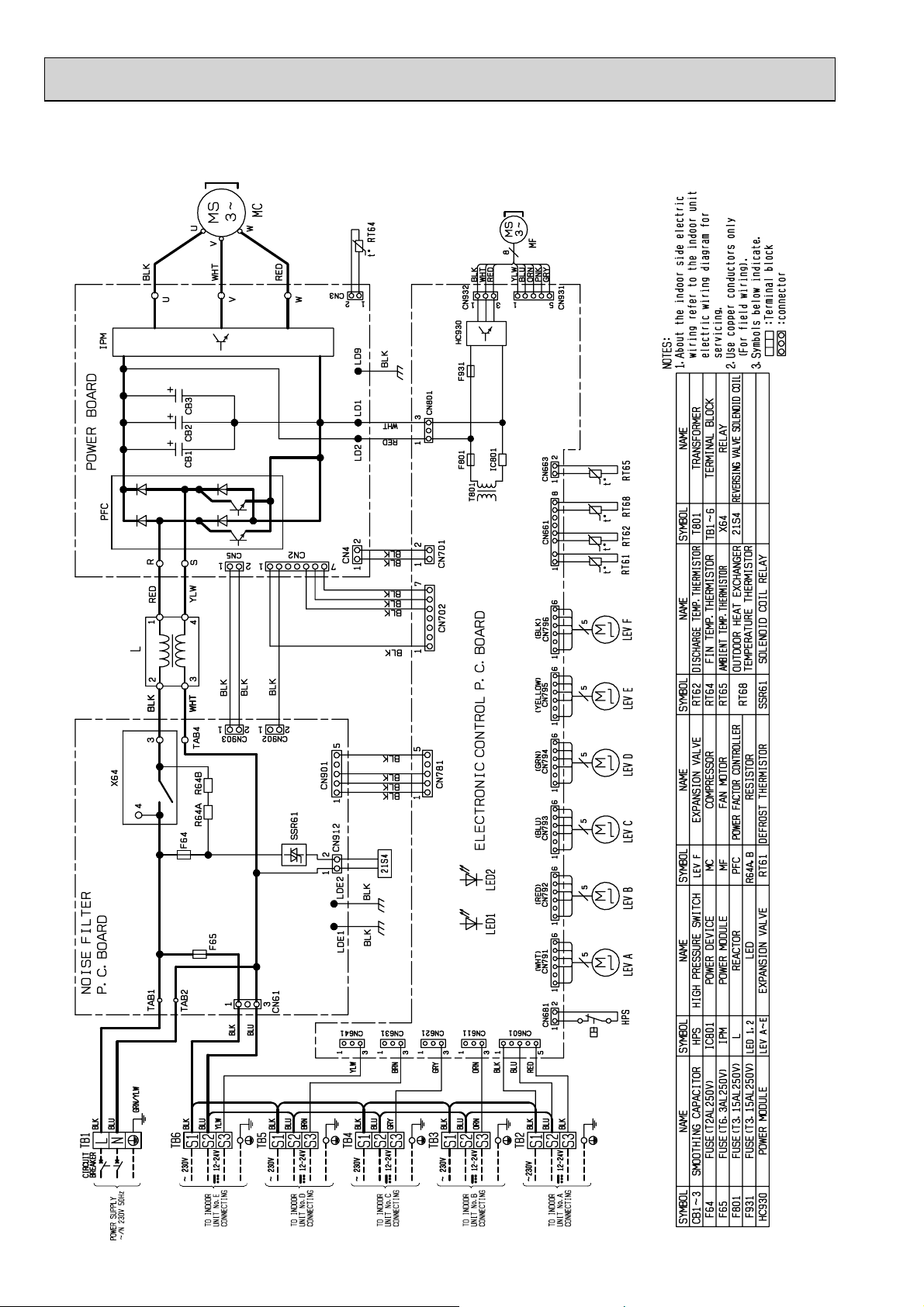
WIRING DIAGRAM
MXZ-2B30VA MXZ-2B40VA MXZ-2B52VA
TB1
TB3
TB2
19
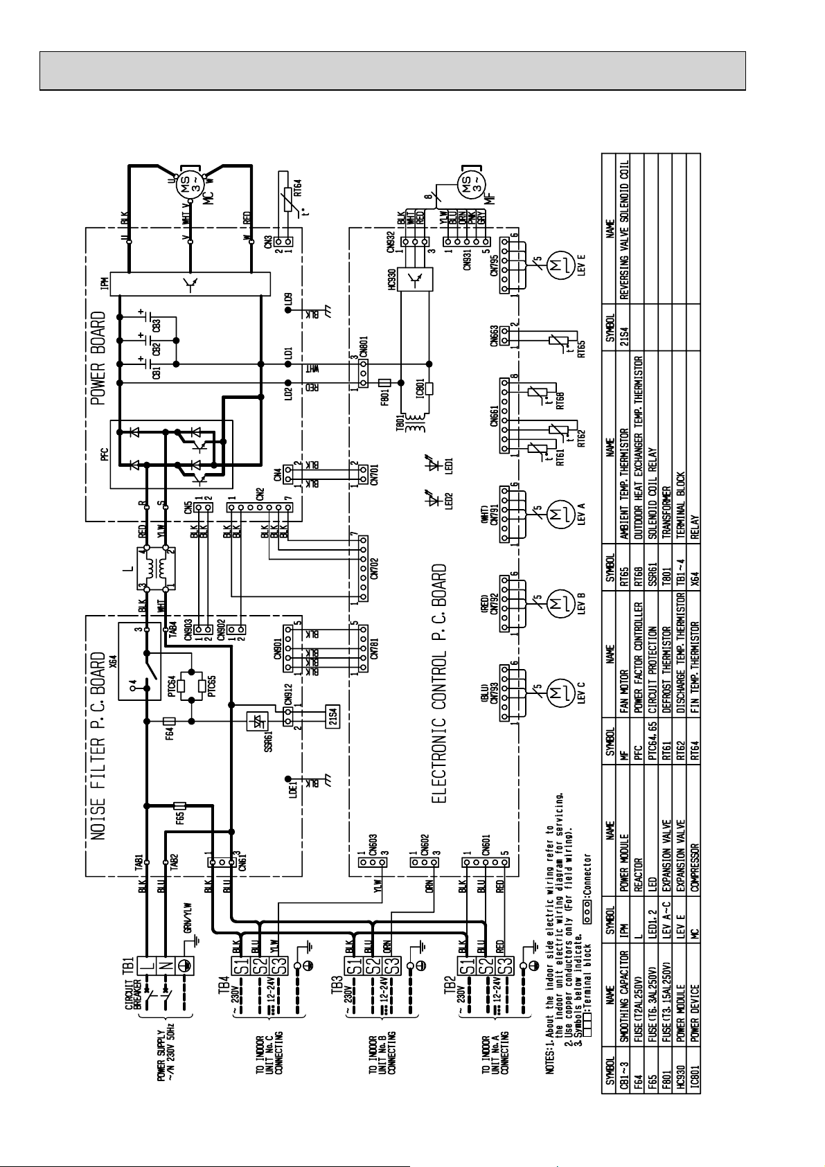
MXZ-3B54VA
20
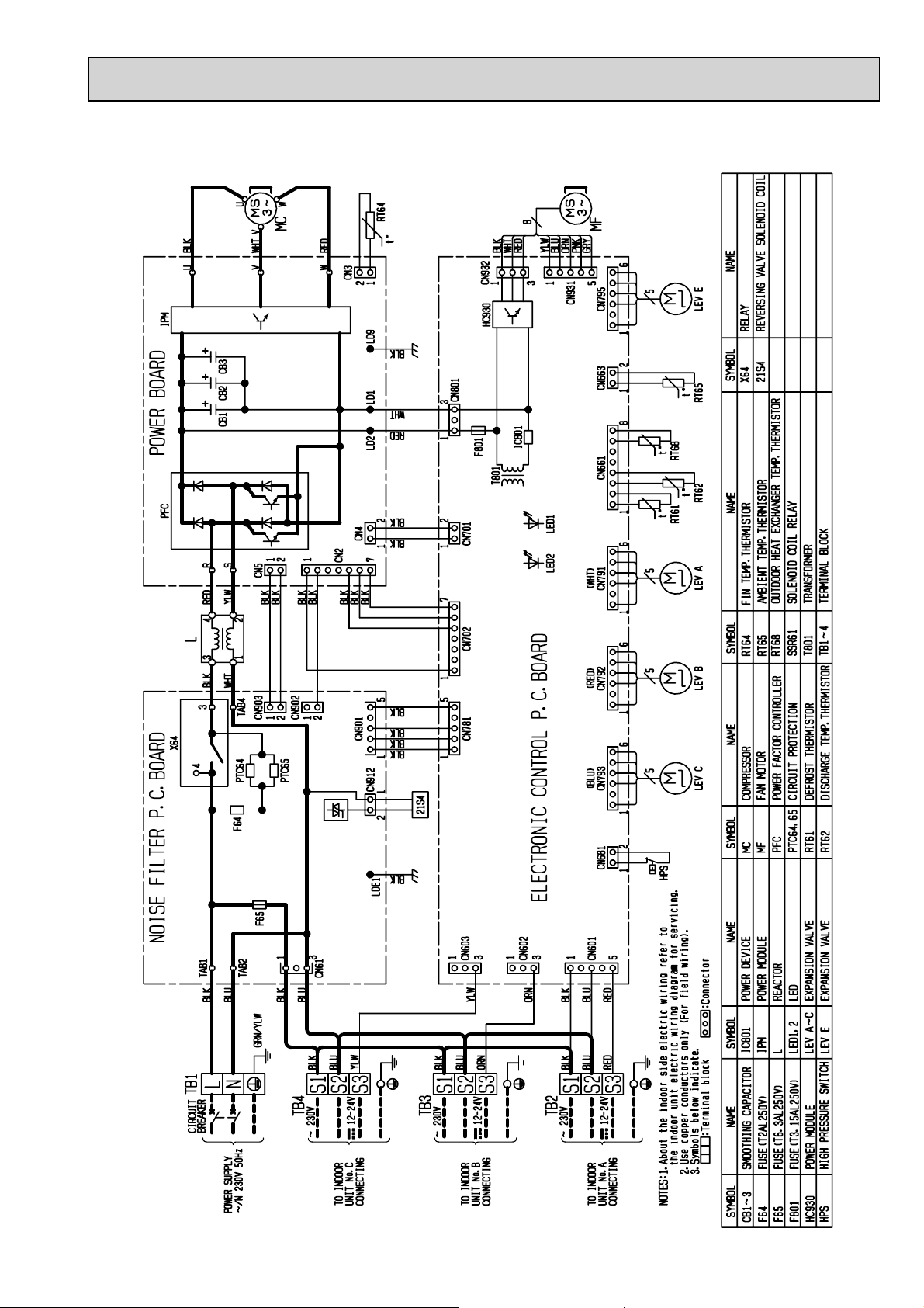
MXZ-3B68VA
21
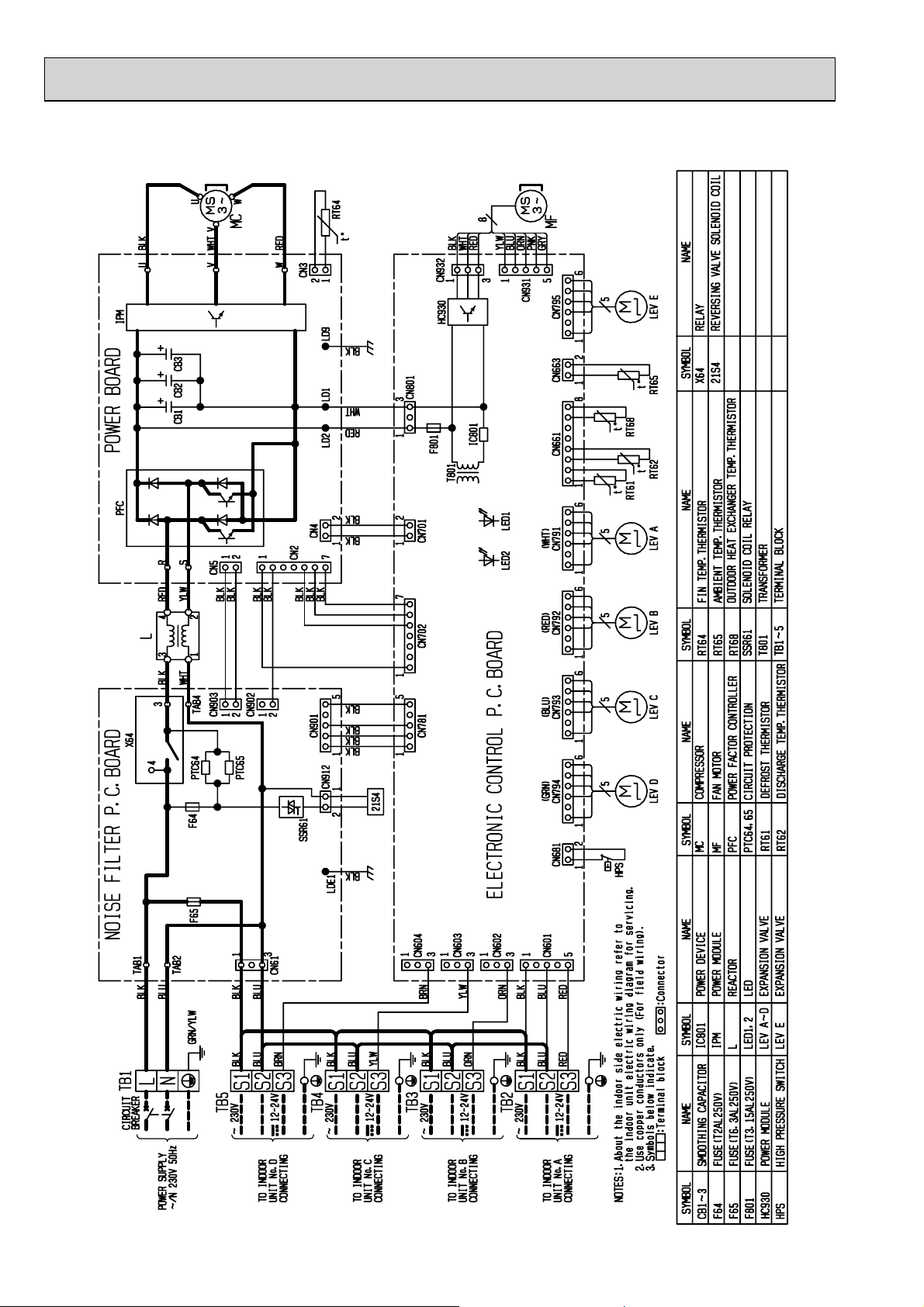
MXZ-4B71VA
22
MXZ-4B80VA
23
MXZ-5B100VA
24
7
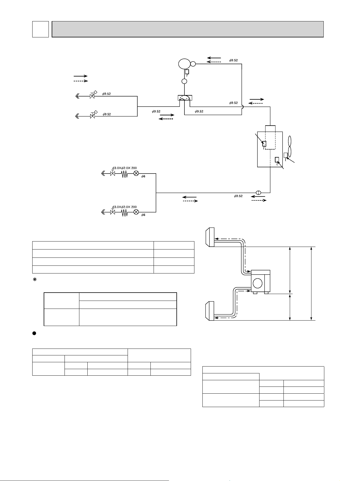
REFRIGERANT SYSTEM DIAGRAM
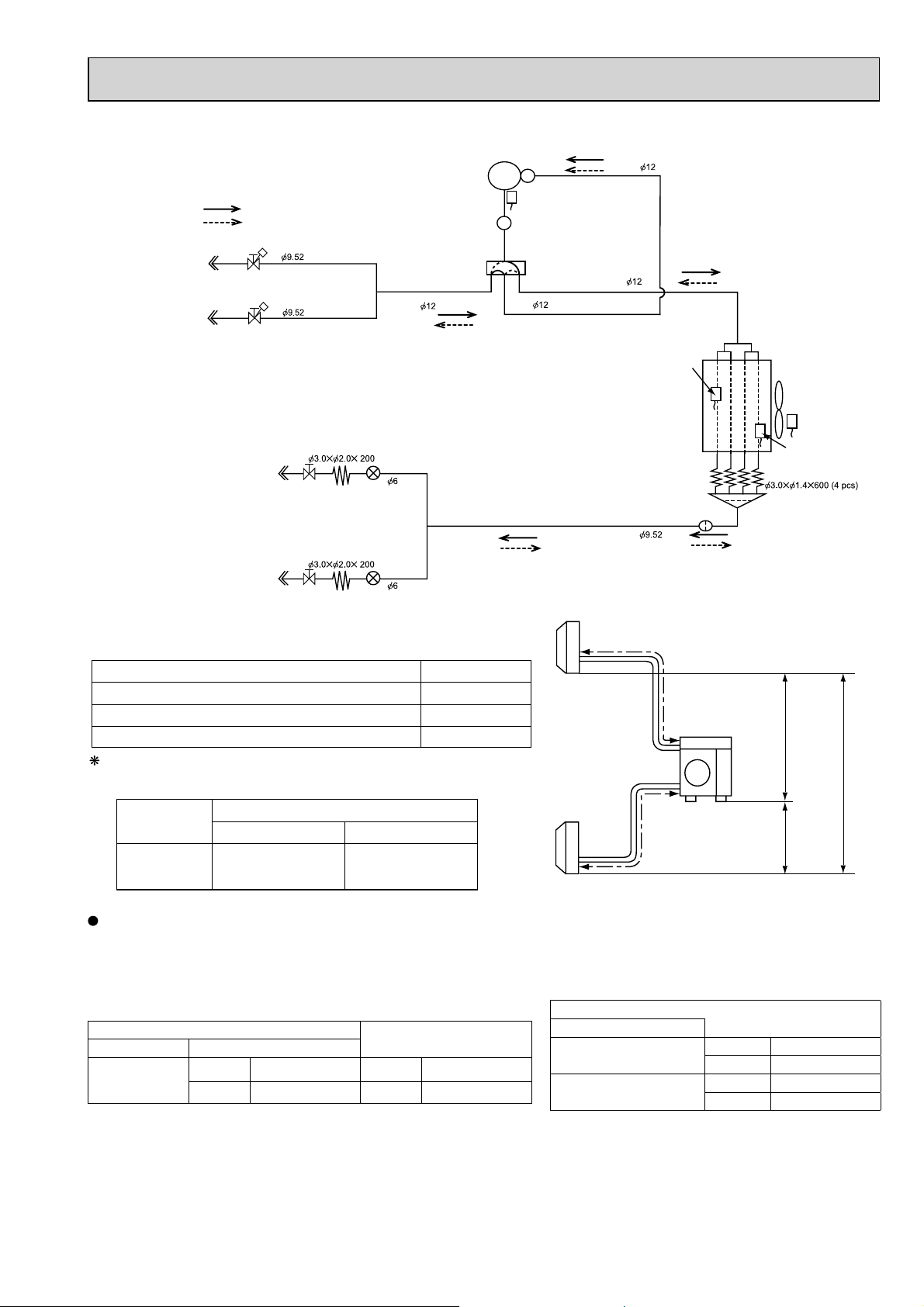
MXZ-2B30VA
R.V. coil
OFF
ON
Indoor unit
B
Indoor unit
A
Refrigerant flow in cooling
Refrigerant flow in heating
Stop valve
(with service port)
Stop valve
(with service port)
Capillary tube
Indoor unit
A
Stop valve
(with strainer #100)
Capillary tube
Indoor unit
B
Stop valve
(with strainer #100)
LEV A
LEV B
Compressor
Discharge
temperature
thermistor RT62
Muffler
4-way valve
Outdoor heat
exchanger
temperature
thermistor
RT68
HEX-OUT
Strainer
#100
FAN-OUT
Defrost
thermistor
RT61
UNIT: mm
Ambient
temperature
thermistor
RT65
MAX REFRIGERANT PIPING LENGTH
Piping length each indoor unit (a, b) 15m
Indoor
units
a
Max.
Height
difference
Total piping length (a+b) 20m
Bending point for each unit 15
Total bending point 20
Outdoor
unit
10m
It is irrelevant which unit is higher.
ADDITIONAL REFRIGERANT CHARGE
Outdoor unit
precharged
(g)
1,150
Refrigerant pipe diameter is different according to indoor unit to be connected. When using extension pipes, refer to the
tables below.
class Pipe diameter
15/20/22/25
Refrigerant piping length (one way, 2 unit total)
20m
0
Indoor unit
Extension pipe diameter
Liquid 6.35(1/4) Liquid 6.35(1/4)
Gas 9.52(3/8) Gas 9.52(3/8)
b
Outdoor unit union diameter
For
Indoor unit A
Indoor unit B
10m
UNIT: mm (inch)
Liquid 6.35(1/4)
Gas 9.52(3/8)
Liquid 6.35(1/4)
Gas 9.52(3/8)
10m
25
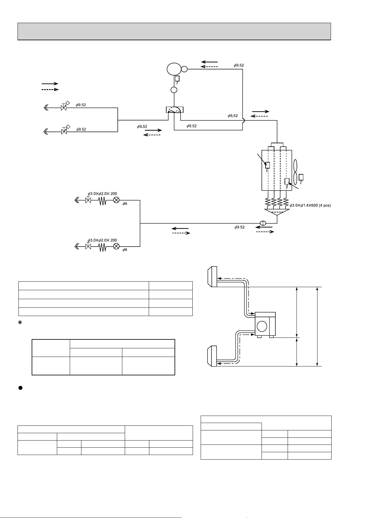
MXZ-2B40VA
R.V. coil
OFF
ON
Refrigerant flow in cooling
Refrigerant flow in heating
Compressor
Discharge
temperature
thermistor RT62
Muffler
UNIT: mm
Indoor unit
B
Indoor unit
A
Stop valve
(with service port)
Stop valve
(with service port)
Indoor unit
A
Indoor unit
B
Capillary tube
Stop valve
(with strainer #100)
Capillary tube
Stop valve
(with strainer #100)
LEV A
LEV B
MAX REFRIGERANT PIPING LENGTH
Piping length each indoor unit (a, b) 20m
Total piping length (a+b) 30m
Bending point for each unit 20
Total bending point 30
4-way valve
Indoor
units
a
Outdoor heat
exchanger
temperature
thermistor
RT68
HEX-OUT
Strainer
#100
Outdoor
unit
Capillary tube
Distributor
FAN-OUT
Ambient
temperature
thermistor
RT65
Defrost
thermistor
RT61
Max.
Height
difference
15m
It is irrelevant which unit is higher.
ADDITIONAL REFRIGERANT CHARGE
Outdoor unit
precharged
(g)
1,300
Calculation : Xg = 20 g/m x (Refrigerant piping length (m) - 20)
Refrigerant pipe diameter is different according to indoor unit to be connected. When using extension pipes, refer to the
tables below.
class Pipe diameter
15/20/22/25/35
Refrigerant piping length (one way, 2 unit total)
20m
0
Indoor unit
30m
200
Extension pipe diameter
Liquid 6.35(1/4) Liquid 6.35(1/4)
Gas 9.52(3/8) Gas 9.52(3/8)
26
b
Outdoor unit union diameter
For
Indoor unit A
Indoor unit B
10m
UNIT: mm (inch)
Liquid 6.35(1/4)
Gas 9.52(3/8)
Liquid 6.35(1/4)
Gas 9.52(3/8)
15m
MXZ-2B52VA
R.V. coil
OFF
ON
Refrigerant flow in cooling
Refrigerant flow in heating
Compressor
Discharge
temperature
thermistor RT62
Muffler
UNIT: mm
Indoor unit
B
Indoor unit
A
Stop valve
(with service port)
Stop valve
(with service port)
Indoor unit
A
Indoor unit
B
Capillary tube
Stop valve
(with strainer #100)
Capillary tube
Stop valve
(with strainer #100)
LEV A
LEV B
MAX REFRIGERANT PIPING LENGTH
Piping length each indoor unit (a, b) 20m
Total piping length (a+b) 30m
Bending point for each unit 20
Total bending point 30
It is irrelevant which unit is higher.
ADDITIONAL REFRIGERANT CHARGE
Outdoor unit
precharged
(g)
1,300
Refrigerant piping length (one way, 2 unit total)
20m
0
30m
200
4-way valve
Indoor
units
Outdoor heat
exchanger
temperature
thermistor
RT68
HEX-OUT
Strainer
#100
a
Distributor
FAN-OUT
Ambient
temperature
thermistor
RT65
Defrost
thermistor
RT61
Capillary tube
Max.
Height
difference
Outdoor
unit
15m
15m
10m
b
Calculation : Xg = 20 g/m x (Refrigerant piping length(m) - 20)
Refrigerant pipe diameter is different according to indoor unit to be connected. When using extension pipes, refer to the
tables below.
UNIT: mm (inch)
Outdoor unit union diameter
Indoor unit
class Pipe diameter
15/20/22/
25/35/42
Liquid 6.35(1/4) Liquid 6.35(1/4)
Gas 9.52(3/8) Gas 9.52(3/8)
Extension pipe diameter
For
Indoor unit A
Indoor unit B
Liquid 6.35(1/4)
Gas 9.52(3/8)
Liquid 6.35(1/4)
Gas 9.52(3/8)
27
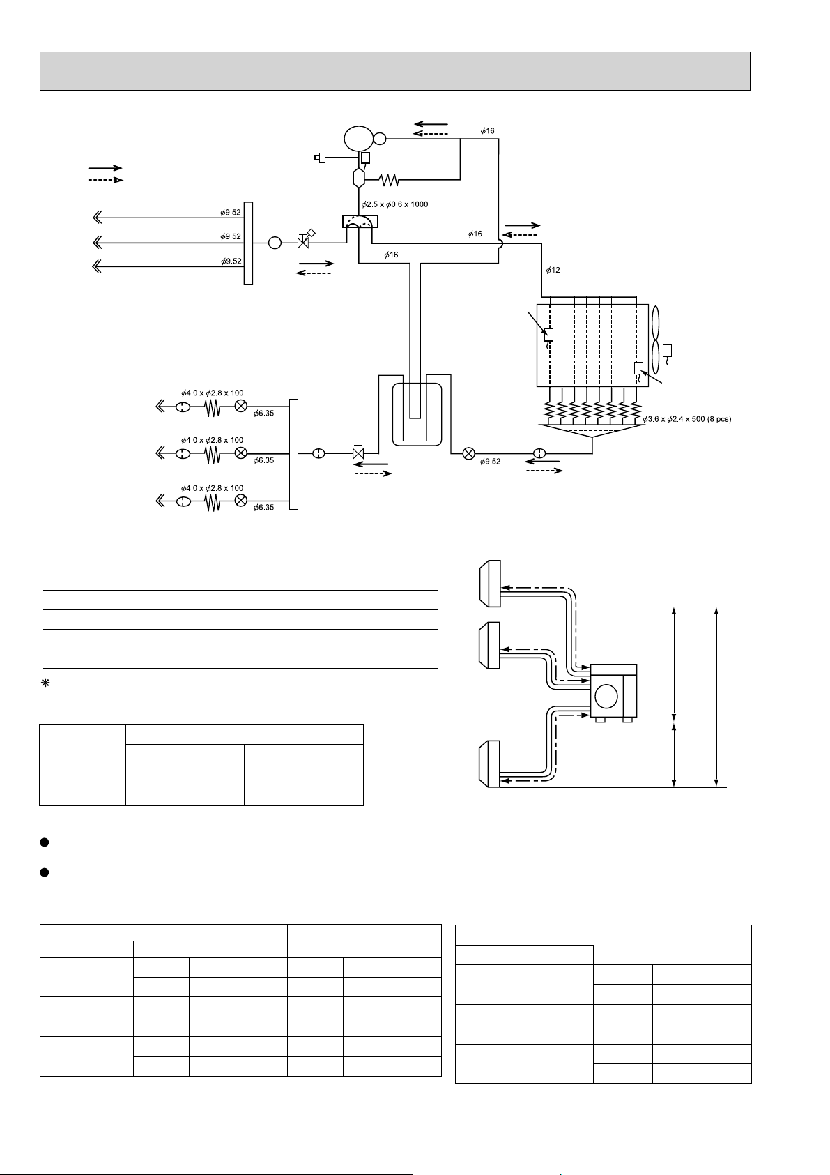
MXZ-3B54VA MXZ-3B68VA
R.V. coil
OFF
ON
Indoor unit
C
Indoor unit
B
Indoor unit
A
Refrigerant flow in cooling
Refrigerant flow in heating
Capillary tube
Indoor unit
A
Strainer
#100
Capillary tube
Indoor unit
B
Indoor unit
C
Strainer
#100
Capillary tube
Strainer
#100
LEV A
LEV B
LEV C
High-pressure switch
(MXZ-3B68VA only)
Oil separator
Stop valve with
service port
Muffler
Strainer
#100
Compressor
Stop valve
Discharge
temperature
thermistor RT62
Capillary tube
4-way valve
Power
receiver
LEV E
Outdoor heat
exchanger
temperature
thermistor
RT68
HEX-OUT
Strainer
#100
Distributor
FAN- OUT
Ambient
temperature
thermistor
RT65
Defrost
thermistor
RT61
Capillary tube
UNIT: mm
MAX REFRIGERANT PIPING LENGTH
Piping length each indoor unit (a, b, c) 25m
Indoor
units
a
Max.
Height
difference
Total piping length (a+b+c) 50m
Bending point for each unit 25
Total bending point 50
b
Outdoor
unit
15m
It is irrelevant which unit is higher.
ADDITIONAL REFRIGERANT CHARGE
Outdoor unit
precharged
(g)
2,700
Calculation : Xg = 20 g/m x (Refrigerant piping length (m) - 40)
Refrigerant pipe diameter is different according to indoor unit to be connected. When using extension pipes, refer to the
tables below.
When diameter of refrigerant pipe is different from that of outdoor unit union, use optional Different-diameter pipe.
For further information on Different-diameter pipe, refer to "PARTS CATALOG".
class Pipe diameter
15/20/22/
25/35/42
50
60
(MXZ-3B68VA)
Refrigerant piping length (one way, 3 unit total)
40m
0
Indoor unit
50m
200
Extension pipe diameter
Liquid 6.35(1/4) Liquid 6.35(1/4)
Gas 9.52(3/8) Gas 9.52(3/8)
Liquid 6.35(1/4) Liquid 6.35(1/4)
Gas 12.7(1/2) Gas 12.7(1/2)
Liquid 6.35(1/4) Liquid 6.35(1/4)
Gas 15.88(5/8) Gas 15.88(5/8)
c
Outdoor unit union diameter
For
Indoor unit A
Indoor unit B
Indoor unit C
10m
UNIT: mm (inch)
Liquid 6.35(1/4)
Gas 9.52(3/8)
Liquid 6.35(1/4)
Gas 9.52(3/8)
Liquid 6.35(1/4)
Gas 9.52(3/8)
15m
28
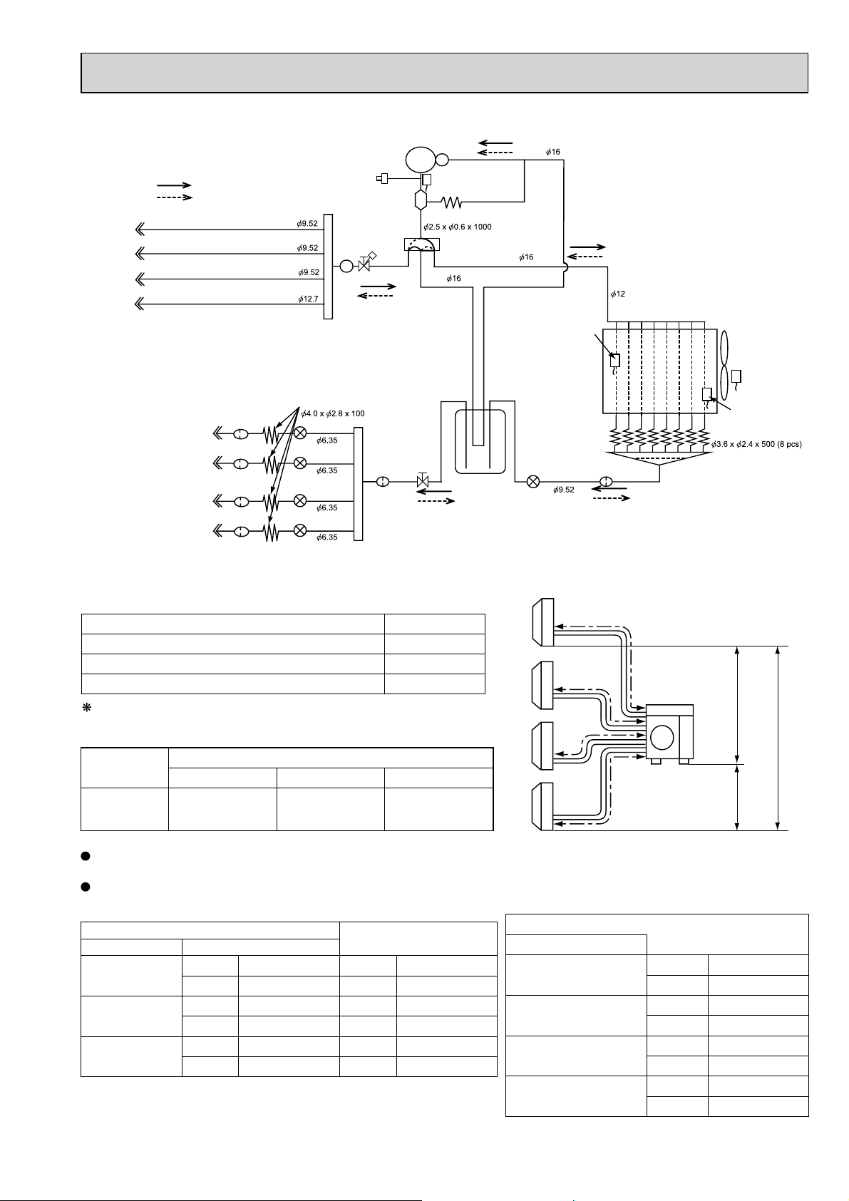
MXZ-4B71VA
UNIT: mm
R.V. coil
OFF
ON
Indoor unit
D
Indoor unit
C
Indoor unit
B
Indoor unit
A
Refrigerant flow in cooling
Refrigerant flow in heating
Indoor unit
A
Indoor unit
B
Indoor unit
C
Indoor unit
D
Strainer
#100
Strainer
#100
Strainer
#100
Strainer
#100
Capillary tube
LEV A
LEV B
LEV C
LEV D
High-pressure
switch
Oil separator
Stop valve with
service port
Muffler
Strainer
#100
Compressor
Capillary tube
Stop valve
Discharge
temperature
thermistor RT62
4-way valve
Power
receiver
LEV E
Outdoor heat
exchanger
temperature
thermistor
RT68
HEX-OUT
Strainer
#100
Distributor
FAN- OUT
Ambient
temperature
thermistor
RT65
Defrost
thermistor
RT61
Capillary tube
MAX REFRIGERANT PIPING LENGTH
Piping length each indoor unit (a, b, c, d) 25m
Total piping length (a+b+c+d) 60m
Indoor
units
a
Max.
Height
difference
Bending point for each unit 25
Total bending point 60
It is irrelevant which unit is higher.
b
Outdoor
unit
15m
ADDITIONAL REFRIGERANT CHARGE
Outdoor unit
precharged
(g)
2,700
Refrigerant piping length (one way, 4 unit total)
40m
0
50m
200
60m
400
Calculation : Xg = 20 g/m x (Refrigerant piping length (m) - 40)
Refrigerant pipe diameter is different according to indoor unit to be connected. When using extension pipes, refer to the
tables below.
When diameter of refrigerant pipe is different from that of outdoor unit union, use optional Different-diameter pipe.
For further information on Different-diameter pipe, refer to "PARTS CATALOG".
Indoor unit
class Pipe diameter
15/20/22/25/35/42
50
60
Liquid 6.35(1/4) Liquid 6.35(1/4)
Gas 9.52(3/8) Gas 9.52(3/8)
Liquid 6.35(1/4) Liquid 6.35(1/4)
Gas 12.7(1/2) Gas 12.7(1/2)
Liquid 6.35(1/4) Liquid 6.35(1/4)
Gas 15.88(5/8) Gas 15.88(5/8)
Extension pipe diameter
c
d
Outdoor unit union diameter
For
Indoor unit A
Indoor unit B
Indoor unit C
Indoor unit D
10m
UNIT: mm (inch)
Liquid 6.35(1/4)
Gas 12.7(1/2)
Liquid 6.35(1/4)
Gas 9.52(3/8)
Liquid 6.35(1/4)
Gas 9.52(3/8)
Liquid 6.35(1/4)
Gas 9.52(3/8)
15m
29
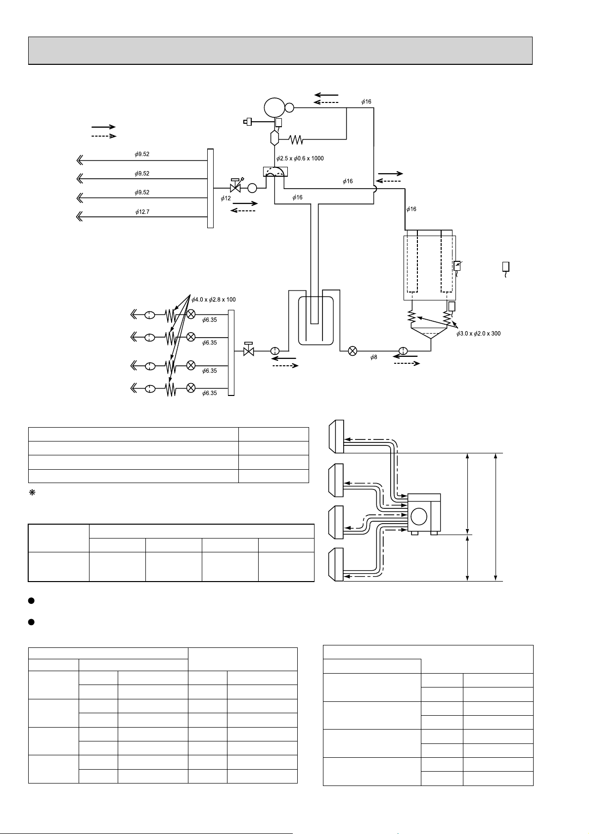
MXZ-4B80VA
UNIT: mm
Oil separator
Muffler
Compressor
Strainer
#100
R.V. coil
OFF
ON
Indoor unit
D
Indoor unit
C
Indoor unit
B
Indoor unit
A
Refrigerant flow in cooling
Refrigerant flow in heating
Indoor unit
A
Indoor unit
B
Indoor unit
C
Indoor unit
D
Strainer
#100
Strainer
#100
Strainer
#100
Strainer
#100
Capillary tube
LEV A
LEV B
LEV C
LEV D
High-pressure
switch
Stop valve
(with service port)
Stop valve
MAX REFRIGERANT PIPING LENGTH
Piping length each indoor unit (a, b, c, d) 25m
Total piping length (a+b+c+d) 70m
Bending point for each unit 25
Total bending point 70
It is irrelevant which unit is higher.
ADDITIONAL REFRIGERANT CHARGE
Outdoor unit
precharged
(g)
3,500
Refrigerant piping length (one way, 4 unit total)
40m
0
50m
200
60m
400
70m
Discharge
temperature
thermistor RT62
Capillary tube
4-way valve
600
Power
receiver
Indoor
units
LEV F
Outdoor
heat
exchanger
Outdoor heat
exchanger
temperature
thermistor
RT68
Defrost
thermistor
RT61
Strainer
#100
a
Capillary tube
Distributor
Max.
Height
Ambient
temperature
thermistor
RT65
difference
b
c
Outdoor
unit
15m
15m
10m
d
Calculation : Xg = 20 g/m x (Refrigerant piping length (m) - 40)
Refrigerant pipe diameter is different according to indoor unit to be connected. When using extension pipes, refer to the
tables below.
When diameter of refrigerant pipe is different from that of outdoor unit union, use optional Different-diameter pipe.
For further information on Different-diameter pipe, refer to "PARTS CATALOG".
Indoor unit
class Pipe diameter
15/20/22/
25/35/42
50
60
71
Liquid 6.35(1/4) Liquid 6.35(1/4)
Gas 9.52(3/8) Gas 9.52(3/8)
Liquid 6.35(1/4) Liquid 6.35(1/4)
Gas 12.7(1/2) Gas 12.7(1/2)
Liquid 6.35(1/4) Liquid 6.35(1/4)
Gas 15.88(5/8) Gas 15.88(5/8)
Liquid 9.52(3/8) Liquid 9.52(3/8)
Gas 15.88(5/8) Gas 15.88(5/8)
Extension pipe diameter
Outdoor unit union diameter
For
Indoor unit A
Indoor unit B
Indoor unit C
Indoor unit D
Liquid 6.35(1/4)
Liquid 6.35(1/4)
Liquid 6.35(1/4)
Liquid 6.35(1/4)
UNIT: mm (inch)
Gas 12.7(1/2)
Gas 9.52(3/8)
Gas 9.52(3/8)
Gas 9.52(3/8)
30

MXZ-5B100VA
Oil separator
Muffler
Stop valve
Compressor
Capillary tube
Strainer
#100
R.V. coil
OFF
ON
Indoor unit
E
Indoor unit
D
Indoor unit
C
Indoor unit
B
Indoor unit
A
Refrigerant flow in cooling
Refrigerant flow in heating
Indoor unit
A
Indoor unit
B
Indoor unit
C
Indoor unit
D
Indoor unit
E
Strainer
#100
Strainer
#100
Strainer
#100
Strainer
#100
Strainer
#100
Capillary tube
LEV A
LEV B
LEV C
LEV D
LEV E
High-pressure
switch
Stop valve
(with service port)
MAX REFRIGERANT PIPING LENGTH
Piping length each indoor unit (a, b, c, d,e) 25m
Total piping length (a+b+c+d+e) 80m
Bending point for each unit 25
Total bending point 80
It is irrelevant which unit is higher.
ADDITIONAL REFRIGERANT CHARGE
Outdoor unit
precharged
(g)
4,000
Refrigerant piping length (one way, 5 unit total)
40m
0
50m
200
60m
400
70m
600
Discharge
temperature
thermistor RT62
4-way valve
Power
receiver
80m
800
LEV F
Indoor
units
UNIT: mm
Outdoor
heat
exchanger
Outdoor heat
exchanger
temperature
thermistor
RT68
Defrost
thermistor
RT61
Strainer
#100
a
Capillary tube
Distributor
Max.
Height
difference
b
Outdoor
unit
c
d
e
15m
10m
Ambient
temperature
thermistor
RT65
15m
Calculation : Xg = 20 g/m x (Refrigerant piping length (m) - 40)
Refrigerant pipe diameter is different according to indoor unit to be connected. When using extension pipes, refer to the
tables below.
When diameter of refrigerant pipe is different from that of outdoor unit union, use optional Different-diameter pipe.
For further information on Different-diameter pipe, refer to "PARTS CATALOG".
UNIT: mm (inch)
Outdoor unit union diameter
Indoor unit
class Pipe diameter
15/20/22/
25/35/42
50
60
71
Liquid 6.35(1/4) Liquid 6.35(1/4)
Gas 9.52(3/8) Gas 9.52(3/8)
Liquid 6.35(1/4) Liquid 6.35(1/4)
Gas 12.7(1/2) Gas 12.7(1/2)
Liquid 6.35(1/4) Liquid 6.35(1/4)
Gas 15.88(5/8) Gas 15.88(5/8)
Liquid 9.52(3/8) Liquid 9.52(3/8)
Gas 15.88(5/8) Gas 15.88(5/8)
Extension pipe diameter
For
Indoor unit A
Indoor unit B
Indoor unit C
Indoor unit D
Indoor unit E
Liquid 6.35(1/4)
Gas 12.7(1/2)
Liquid 6.35(1/4)
Gas 9.52(3/8)
Liquid 6.35(1/4)
Gas 9.52(3/8)
Liquid 6.35(1/4)
Gas 9.52(3/8)
Liquid 6.35(1/4)
Gas 9.52(3/8)
31

8
PERFORMANCE CURVES
MXZ-2B30VA MXZ-2B40VA MXZ-2B52VA MXZ-3B54VA
MXZ-3B68VA MXZ-4B71VA MXZ-4B80VA MXZ-5B100VA
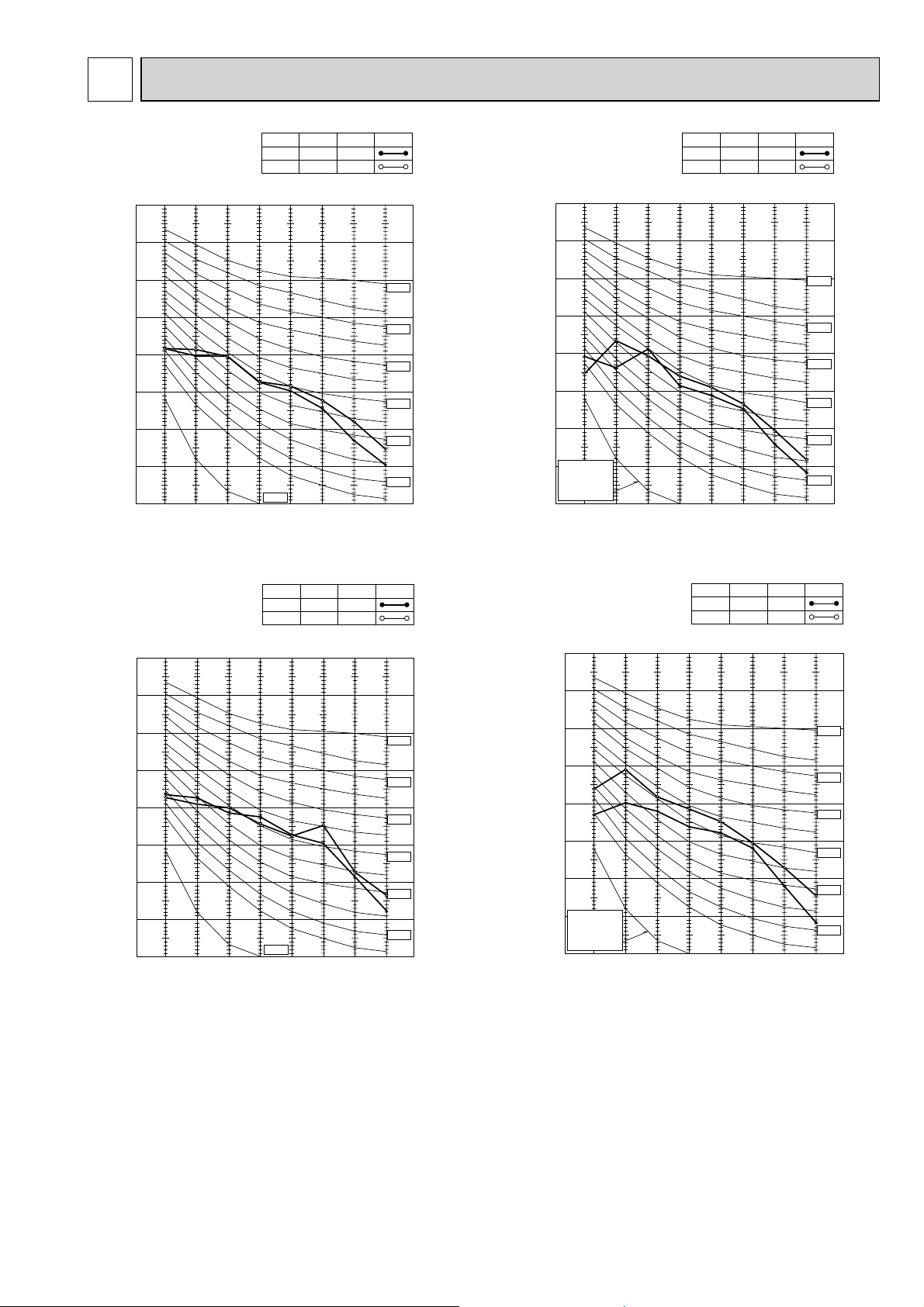
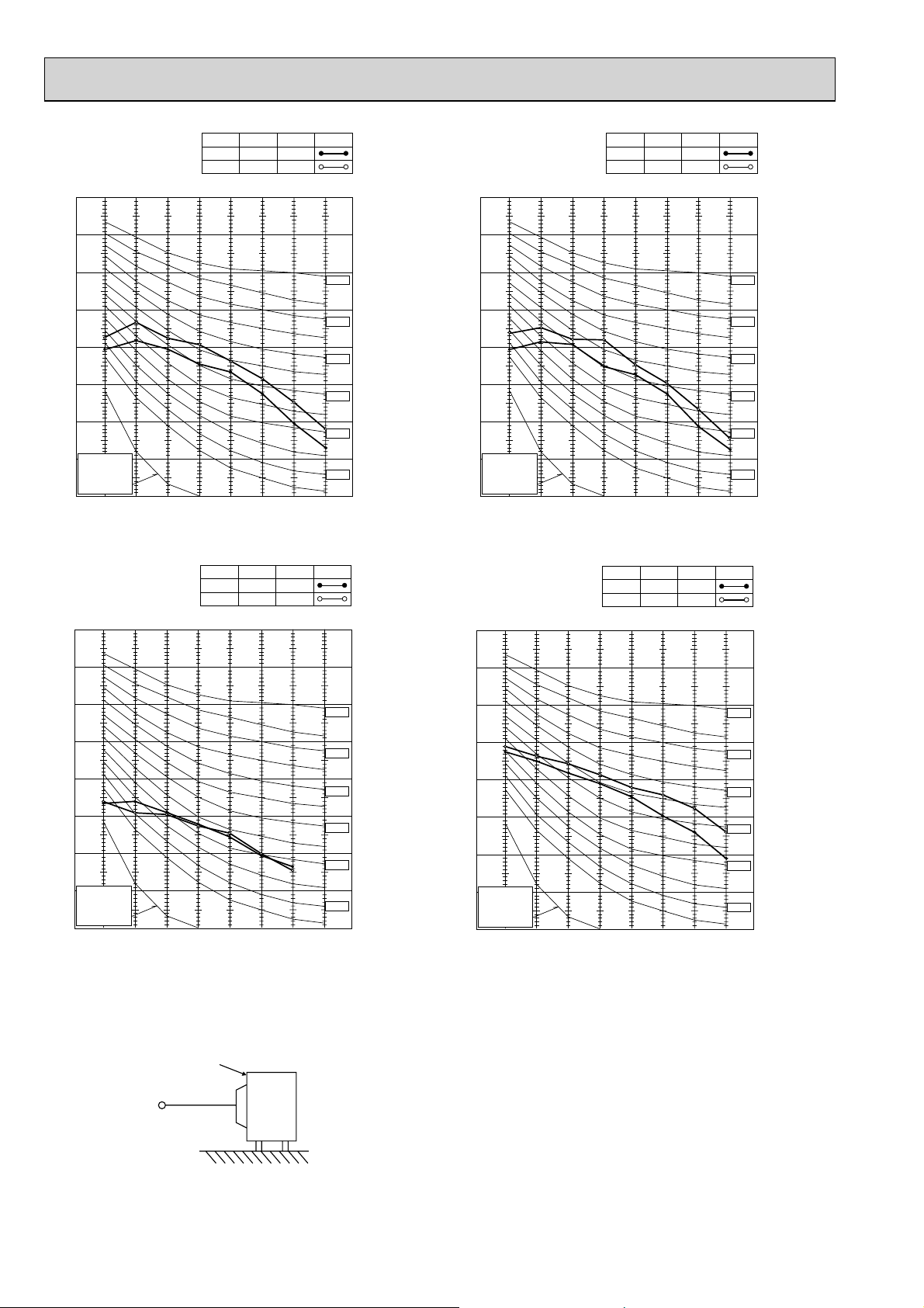
The standard specifications apply only to the operation of the air conditioner under normal conditions.
Since operating conditions vary according to the areas where these units are installed, the following information has been pro-
vided to clarify the operating characteristics of the air conditioner under the conditions indicated by the performance curve.
(1) GUARANTEED VOLTAGE
198~264 V 50 Hz
(2) AIR FLOW
Air flow should be set at MAX.
(3) MAIN READINGS
(1) Indoor intake air wet-bulb temperature : °CWB
(2) Indoor outlet air wet-bulb temperature : °CWB
(3) Outdoor intake air dry-bulb temperature : °CDB
(4) Total input: W
(5) Indoor intake air dry-bulb temperature : °CDB
(6) Outdoor intake air wet-bulb temperature : °CWB
(7) Total input : W
Indoor air wet/dry-bulb temperature difference on the left side of the following chart shows the difference between the
indoor intake air wet/dry-bulb temperature and the indoor outlet air wet/dry-bulb temperature for your reference at service.
How to measure the indoor air wet-bulb/dry-bulb temperature difference
1. Attach at least 2 sets of wet and dry-bulb thermometers to the indoor air intake as shown in the figure, and at least 2 sets
of wet and dry-bulb thermometers to the indoor air outlet. The thermometers must be attached to the position where air
speed is high.
2. Attach at least 2 sets of wet and dry-bulb thermometers to the outdoor air intake.
Cover the thermometers to prevent direct rays of the sun.
3. Check that the air filter is cleaned.
4. Open windows and doors of room.
5. Press the EMERGENCY OPERATION switch once (twice) to start the EMERGENCY COOL
(HEAT) MODE.
6. When system stabilizes after more than 15 minutes, measure temperature and take an average temperature.
7. 10 minutes later, measure temperature again and check that the temperature does not change.
Cooling
}
Heating
}
INDOOR UNIT
Wet and dry-bulb
thermometers
FRONT VIEW
OUTDOOR UNIT
Wet-and dry-bulb
thermometers
BACK VIEW
32

8-1. CAPACITY AND THE INPUT CURVES
MXZ-2B30VA
MXZ-2B40VA
MXZ-2B52VA
8.0
6.3
7.3
5.8
6.7
5.3
6.0
4.8
5.4
4.3
4.8
3.9
Indoor air Wet-bulb temperature
15 class
20 class
19.7
15.8
18.2
14.5
16.7
13.2
15.2
11. 8
13.6
10.5
12.1
9.2
7.9
10.6
9.1
15 class
20 class
Indoor air Dry-bulb temperature
8.5
7.8
7.1
6.4
5.8
5.1
25.417.1
23.4
21.5
19.5
17.6
15.6
13.7
11. 7
9.3
8.5
7.8
7.0
6.3
5.6
22 class
24.0
22.2
20.3
18.5
16.6
14.8
12.9
11. 1
22 class
10.6
9.7
8.8
7.9
7.1
6.3
35 class
25 class
25.9
23.9
21.9
19.9
17.9
15.9
13.9
12.0
25 class
35 class
9.5
8.7
8.0
7.2
6.5
5.7
42 class
27.0
24.9
22.8
20.7
18.7
16.6
14.5
12.4
42 class
Indoor intake air Wet-bulb temperature (°C)
bulb temperature (°C)
Indoor intake air Wet-
Outdoor intake air Dry-bulb temperature (°C) Outdoor intake air Dry-bulb temperature (°C)
(MXZ-2B52VA)
Indoor intake air Dry-bulb temperature (°C)
Indoor intake air Dry-bulb temperature (°C)
Outdoor intake air Wet-bulb temperature (°C) Outdoor intake air Wet-bulb temperature (°C)
(MXZ-2B52VA)
MXZ-3B54VA MXZ-3B68VA MXZ-4B71VA
9.5
13.1
11. 9
10.8
9.7
8.7
7.7
50 class
31.9
29.4
27.0
24.5
22.1
19.6
17.2
14.7
50 class
13.7
12.4
11. 3
10.1
9.0
Indoor
intake air Wet-bulb temperature (°C)
8.0
Outdoor intake air Dry-bulb temperature (°C) Outdoor intake air Dry-bulb temperature (°C)
60 class
Indoor intake air Dry-bulb temperature (°C)
Outdoor intake air Wet-bulb temperature (°C) Outdoor intake air Wet-bulb temperature (°C)
60 class
8.0
7.3
6.7
6.0
5.4
4.8
19.7
18.2
16.7
15.2
13.6
12.1
10.6
9.1
20 class
8.5
7.8
7.1
6.4
5.8
5.1
20 class
25.417.1
23.4
21.5
19.5
17.6
15.6
13.7
11. 7
22 class
24.0
22.2
20.3
18.5
16.6
14.8
12.9
11. 1
22 class
25 class
6.3
5.8
5.3
4.8
4.3
3.9
Indoor air Wet-bulb temperature
15 class
15.8
14.5
13.2
11. 8
10.5
9.2
Indoor air Dry-bulb temperature
7.9
15 class
10.6
9.3
8.5
7.8
7.0
6.3
5.6
25 class
25.9
23.9
21.9
19.9
17.9
15.9
13.9
12.0
9.7
8.8
7.9
7.1
6.3
35 class
27.0
24.9
22.8
20.7
18.7
16.6
14.5
12.4
35 class
8.7
8.0
7.2
6.5
5.7
42 class
31.4
29.0
26.6
24.1
21.7
19.3
16.9
14.5
42 class
Indoor intake air Wet-bulb temperature (°C)
bulb temperature (°C)
Indoor intake air Dry-
33

MXZ-4B80VA
8.0
6.3
7.3
5.8
6.7
5.3
6.0
4.8
5.4
4.3
4.8
3.9
Indoor air Wet-bulb temperature
15 class
20 class
8.0
6.3
7.3
5.8
6.7
5.3
6.0
4.8
5.4
4.3
4.8
3.9
Indoor air Wet-bulb temperature
15 class
20 class
19.7
17.1
18.2
15.8
16.7
14.5
15.2
13.2
13.6
11. 8
12.1
10.5
10.6
9.2
Indoor air Dry-bulb temperature
7.9
13.7
9.1
25.4
23.4
21.5
19.5
17.6
15.6
11. 7
8.5
7.8
7.1
6.4
5.8
5.1
22 class
8.5
7.8
7.1
6.4
5.8
5.1
22 class
9.3
8.5
7.8
7.0
6.3
5.6
9.3
8.5
7.8
7.0
6.3
5.6
24.0
22.2
20.3
18.5
16.6
14.8
12.9
11. 1
10.6
9.7
8.8
7.9
7.1
6.3
25 class
10.6
9.7
8.8
7.9
7.1
6.3
25 class
25.9
23.9
21.9
19.9
17.9
15.9
13.9
12.0
35 class
35 class
27.0
24.9
22.8
20.7
18.7
16.6
14.5
12.4
9.5
8.7
8.0
7.2
6.5
5.7
42 class
9.5
8.7
8.0
7.2
6.5
5.7
42 class
31.4
29.0
26.6
24.1
21.7
19.3
16.9
14.5
13.1
11. 9
10.8
9.7
8.7
7.7
13.1
11. 9
10.8
9.7
8.7
7.7
50 class
50 class
31.9
29.4
27.0
24.5
22.1
19.6
17.2
14.7
13.7
12.4
11. 3
10.1
9.0
8.0
60 class
13.7
12.4
11. 3
10.1
9.0
8.0
60 class
35.1
32.4
29.7
27.0
24.3
21.6
18.9
16.2
17.0
15.4
13.9
12.5
11. 1
9.7
17.0
15.4
13.9
12.5
11. 1
9.7
71 class
71 class
Indoor inta
ke air Wet-bulb temperature (°C)
Outdoor intake air Dry-bulb temperature (°C)
Indoor intake air Wet-bulb temperature (°C)
Outdoor intake air Dry-bulb temperature (°C)
ure (°C)
ke air Dry-bulb temperat
Indoor inta
15 class
20 class
22 class
25 class
19.7
17.1
15.8
14.5
13.2
11. 8
10.5
9.2
Indoor air Dry-bulb temperature
7.9
15 class
18.2
16.7
15.2
13.6
12.1
10.6
9.1
20 class
25.4
23.4
21.5
19.5
17.6
15.6
13.7
11. 7
24.0
22.2
20.3
18.5
16.6
14.8
12.9
11. 1
22 class
25 class
35 class
25.9
23.9
21.9
19.9
17.9
15.9
13.9
12.0
35 class
42 class
27.0
24.9
22.8
20.7
18.7
16.6
14.5
12.4
42 class
50 class
31.4
29.0
26.6
24.1
21.7
19.3
16.9
14.5
50 class
60 class
31.9
29.4
27.0
24.5
22.1
19.6
17.2
14.7
60 class
35.1
32.4
29.7
27.0
24.3
21.6
18.9
16.2
Outdoor intake air Wet-bulb temperature (°C)
71 class
Indoor intake air Dry-bulb temperature (°C)
Outdoor intake air Wet-bulb temperature (°C)
71 class
34

MXZ-5B100VA
8.5
8.0
6.3
7.8
7.3
5.8
7.1
6.7
5.3
6.4
6.0
4.8
5.8
5.4
4.3
5.1
4.8
3.9
Indoor air Wet-bulb temperature
15 class
20 class
8.0
7.3
6.7
6.0
5.4
4.8
8.5
7.8
7.1
6.4
5.8
5.1
20 class
6.3
5.8
5.3
4.8
4.3
3.9
Indoor air Wet-bulb temperature
15 class
22 class
22 class
9.3
8.5
7.8
7.0
6.3
5.6
25 class
9.3
8.5
7.8
7.0
6.3
5.6
25 class
10.6
9.7
8.8
7.9
7.1
6.3
10.6
9.7
8.8
7.9
7.1
6.3
35 class
35 class
9.5
8.7
8.0
7.2
6.5
5.7
42 class
9.5
8.7
8.0
7.2
6.5
5.7
42 class
13.1
11. 9
10.8
9.7
8.7
7.7
13.1
11. 9
10.8
9.7
8.7
7.7
50 class
50 class
13.7
12.4
11. 3
10.1
9.0
8.0
60 class
13.7
12.4
11. 3
10.1
9.0
8.0
60 class
17.0
15.4
13.9
12.5
11. 1
9.7
17.0
15.4
13.9
12.5
11. 1
9.7
71 class
71 class
Indoor inta
ke air Wet-bulb temperature (°C)
Outdoor intake air Dry-bulb temperature (°C)
Indoor intake air Wet-bulb temperature (°C)
Outdoor intake air Dry-bulb temperature (°C)
19.7
17.1
15.8
14.5
13.2
11. 8
10.5
9.2
Indoor air Dry-bulb temperature
7.9
17.1
15.8
14.5
13.2
11. 8
10.5
9.2
Indoor air Dry-bulb temperature
7.9
18.2
16.7
15.2
13.6
12.1
10.6
9.1
15 class
20 class
19.7
18.2
16.7
15.2
13.6
12.1
10.6
9.1
15 class
20 class
25.4
23.4
21.5
19.5
17.6
15.6
13.7
11. 7
25.4
23.4
21.5
19.5
17.6
15.6
13.7
11. 7
24.0
22.2
20.3
18.5
16.6
14.8
12.9
11. 1
22 class
25 class
24.0
22.2
20.3
18.5
16.6
14.8
12.9
11. 1
22 class
25 class
25.9
23.9
21.9
19.9
17.9
15.9
13.9
12.0
35 class
25.9
23.9
21.9
19.9
17.9
15.9
13.9
12.0
35 class
27.0
24.9
22.8
20.7
18.7
16.6
14.5
12.4
42 class
27.0
24.9
22.8
20.7
18.7
16.6
14.5
12.4
42 class
31.4
29.0
26.6
24.1
21.7
19.3
16.9
14.5
31.4
29.0
26.6
24.1
21.7
19.3
16.9
14.5
50 class
31.9
29.4
27.0
24.5
22.1
19.6
17.2
14.7
50 class
31.9
29.4
27.0
24.5
22.1
19.6
17.2
14.7
35.1
32.4
29.7
27.0
24.3
21.6
18.9
16.2
60 class
71 class
35.1
32.4
29.7
27.0
24.3
21.6
18.9
16.2
60 class
71 class
Indoor intake air Dry-bulb temperature (°C)
Outdoor intake air Wet-bulb temperature (°C)
Indoor intake air Dry-bulb temperature (°C)
Outdoor intake air Wet-bulb temperature (°C)
35

8-2. CAPACITY AND INPUT CORRECTION BY INVERTER OUTPUT FREQUENCY (single operation)
MXZ-2B30VA
15-class unit
2.0
<COOL>Capacity
2.5
<COOL>Total input
2.0
<HEAT>Capacity
2.5
<HEAT>Total input
1.5
1.0
0.5
0 50 100 150
Frequency
20-class unit
<COOL>Capacity
2.0
1.5
1.0
0.5
0.0
0 50 100 150
Frequency
22-class unit
<COOL>Capacity
1.5
1.0
0.5
2.0
1.5
1.0
0.5
0.0
Hz
050100150
Frequency
<COOL>Total input
2.0
1.5
1.0
0.5
0.0
Hz
0 50 100 150
Frequency
<COOL>Total input
2.0
1.5
1.0
0.5
1.5
1.0
0.5
0.0
Hz
0 50 100 150
Frequency
<HEAT>Capacity <HEAT>Total input
2.0
1.5
1.0
0.5
0.0
0 50 100 150
Hz
1.5
1.0
0.5
Frequency
<HEAT>Capacity <HEAT>Total input
2.0
1.5
1.0
0.5
0.0
Hz
0 50 100 150
Frequency
2.0
1.5
1.0
0.5
0.0
Hz
0 50 100 150
2.0
1.5
1.0
0.5
Frequency
Hz
Hz
0.0
0 50 100 150
Frequency
25-class unit
<COOL>Capacity
1.5
1.0
0.5
0.0
0 50 100 150
Frequency
0.0
Hz
0 50 100 150
Frequency
<COOL>Total input
1.5
1.0
0.5
0.0
Hz
0 50 100 150
Frequency
0.0
0 50 100 150
Hz
1.5
1.0
0.5
0.0
0 50 100 150
Hz
Frequency
<HEAT>Capacity <HEAT>Total input
Frequency
0.0
Hz
0 50 100 150
2.0
1.5
1.0
0.5
0.0
Hz
0 50 100 150
Frequency
Frequency
Hz
Hz
36

MXZ-2B40VA
15-class unit
<COOL>Capacity
2.0
2.5
<COOL>Total input
2.0
<HEAT>Capacity
3.0
<HEAT>Total input
1.5
1.0
0.5
0 50 100 150
Frequency
20-class unit
<COOL>Capacity
1.5
1.0
0.5
0 50 100 150
Frequency
22-class unit
<COOL>Capacity
1.5
1.0
2.0
1.5
1.0
0.5
Hz
0 50 100 150
Frequency
<COOL>Total input
2.0
1.5
1.0
0.5
Hz
0 50 100 150
Frequency
<COOL>Total input
1.5
1.0
1.5
1.0
0.5
Hz
0 50 100 150
Frequency
<HEAT>Capacity <HEAT>Total input
1.5
1.0
0.5
0 50 100 150
Hz
1.5
1.0
Frequency
<HEAT>Capacity
2.5
2.0
1.5
1.0
0.5
0 50 100 150
Hz
Frequency
2.0
1.5
1.0
0.5
Hz
0 50 100 150
Frequency
<HEAT>Total input
1.5
1.0
Hz
Hz
0.5
0 50 100 150
Frequency
25-class unit
<COOL>Capacity
1.5
1.0
0.5
0 50 100 150
Frequency
35-class unit
<COOL>Capacity
1.5
1.0
0.5
0.5
Hz
050100150
1.5
1.0
0.5
Hz
0 50 100 150
1.5
1.0
0.5
Frequency
<COOL>Total input
Frequency
<COOL>Total input
0.5
Hz
0 50 100 150
1.5
1.0
0.5
Hz
0 50 100 150
1.5
1.0
0.5
Frequency
<HEAT>Capacity
Frequency
<HEAT>Capacity
0.5
Hz
0 50 100 150
1.5
1.0
0.5
Hz
0 50 100 150
1.5
1.0
0.5
Frequency
<HEAT>Total input
Frequency
<HEAT>Total input
Hz
Hz
0 50 100 150
Frequency
Hz
0 50 100 150
Frequency
Hz
0 50 100 150
Frequency
37
Hz
0 50 100 150
Frequency
Hz

MXZ-2B52VA
15-class unit
<COOL>Capacity
2.0
3.0
<COOL>Total input
2.0
<HEAT>Capacity
2.5
<HEAT>Total input
1.5
1.0
0.5
0.0
0 50 100 150
Frequency
20-class unit
<COOL>Capacity
1.5
1.0
0.5
0.0
0 50 100 150
Frequency
22-class unit
<COOL>Capacity
1.5
1.0
2.5
2.0
1.5
1.0
0.5
Hz
0 50 100 150
Frequency
<COOL>Total input
2.0
1.5
1.0
0.5
0.0
Hz
050100150
Frequency
<COOL>Total input
1.5
1.0
1.5
1.0
0.5
0.0
Hz
0 50 100 150
Frequency
<HEAT>Capacity
2.0
1.5
1.0
0.5
0.0
Hz
0 50 100 150
Frequency
<HEAT>Capacity
1.5
1.0
2.0
1.5
1.0
0.5
0.0
0 50 100 150
Hz
Frequency
2.0
1.5
1.0
0.5
0.0
Hz
<HEAT>Total input
0 50 100 150
Frequency
<HEAT>Total input
1.5
1.0
Hz
Hz
0.5
0.0
0 50 100 150
Frequency
25-class unit
<COOL>Capacity
1.5
1.0
0.5
0.0
0 50 100 150
Frequency
35-class unit
<COOL>Capacity
1.5
1.0
0.5
0.5
0.0
Hz
0 50 100 150
1.5
1.0
0.5
0.0
Hz
0 50 100 150
1.5
1.0
0.5
Frequency
<COOL>Total input
Frequency
<COOL>Total input
0.5
0.0
Hz
0 50 100 150
1.5
1.0
0.5
0.0
Hz
0 50 100 150
1.5
1.0
0.5
Frequency
<HEAT>Capacity
Frequency
<HEAT>Capacity
0.5
0.0
Hz
0 50 100 150
1.5
1.0
0.5
0.0
Hz
0 50 100 150
1.5
1.0
0.5
Frequency
<HEAT>Total input
Frequency
<HEAT>Total input
Hz
Hz
0 50 100 150
Frequency
Hz
0 50 100 150
Frequency
Hz
0 50 100 150
Frequency
38
Hz
050100150
Frequency
Hz

42-class unit
<COOL>Capacity
1.5
1.5
<COOL>Total input
1.5
<HEAT>Capacity
1.5
<HEAT>Total input
1.0
0.5
0.0
0 50 100 150
Frequency
MXZ-3B54VA
15-class unit
<COOL>Capacity
2.5
2.0
1.5
1.0
0.5
0 50 100 150
Frequency
20-class unit
<COOL>Capacity
2.0
1.0
0.5
0.0
Hz
0 50 100 150
Frequency
<COOL>Total input
2.5
2.0
1.5
1.0
0.5
Hz
0 50 100 150
Hz
Frequency
<COOL>Total input
2.0
1.0
0.5
0.0
Hz
0 50 100 150
Frequency
<HEAT>Capacity <HEAT>Total input
2.5
2.0
1.5
1.0
0.5
0 50 100 150
Hz
Frequency
<HEAT>Capacity <HEAT>Total input
2.0
1.0
0.5
0.0
0 50 100 150
Hz
Frequency
2.5
2.0
1.5
1.0
0.5
Hz
0 50 100 150
Frequency
2.5
Hz
Hz
1.5
1.0
0.5
0 50 100 150
Frequency
22-class unit
<COOL>Capacity
1.5
1.0
0.5
0 50 100 150
Frequency
25-class unit
<COOL>Capacity
1.5
1.0
1.5
1.0
0.5
Hz
050100150
Frequency
<COOL>Total input
1.5
1.0
0.5
Hz
050100150
Frequency
<COOL>Total input
1.5
1.0
1.5
1.0
0.5
Hz
0 50 100 150
Frequency
<HEAT>Capacity
1.5
1.0
0.5
Hz
0 50 100 150
Frequency
<HEAT>Capacity
1.5
1.0
2.0
1.5
1.0
0.5
Hz
0 50 100 150
Frequency
<HEAT>Total input
1.5
1.0
0.5
Hz
0 50 100 150
Frequency
<HEAT>Total input
1.5
1.0
Hz
Hz
0.5
0 50 100 150
Frequency
0.5
Hz
0 50 100 150
Frequency
0.5
Hz
0 50 100 150
Frequency
39
0.5
Hz
0 50 100 150
Frequency
Hz

MXZ-3B54VA
35-class unit
<COOL>Capacity
1.5
1.5
<COOL>Total input
1.5
<HEAT>Capacity
1.5
<HEAT>Total input
1.0
0.5
0 50 100 150
Frequency
42-class unit
<COOL>Capacity
1.5
1.0
0.5
0 50 100 150
Frequency
50-class unit
<COOL>Capacity
1.5
1.0
0.5
Hz
0 50 100 150
1.5
1.0
0.5
Hz
0 50 100 150
1.5
Frequency
<COOL>Total input
Frequency
<COOL>Total input
1.0
0.5
Hz
0 50 100 150
1.5
1.0
0.5
Hz
0 50 100 150
1.5
Frequency
<HEAT>Capacity
Frequency
<HEAT>Capacity
1.0
0.5
Hz
0 50 100 150
1.5
1.0
0.5
Hz
050100150
1.5
Frequency
<HEAT>Total input
Frequency
<HEAT>Total input
Hz
Hz
1.0
0.5
0 50 100 150
Frequency
1.0
0.5
Hz
0 50 100 150
Frequency
1.0
0.5
Hz
0 50 100 150
Frequency
1.0
0.5
Hz
0 50 100 150
Frequency
Hz
40

MXZ-3B68VA
15-class unit
<COOL>Capacity
2.5
2.5
<COOL>Total input
<HEAT>Capacity <HEAT>Total input
2.5
3.0
2.0
1.5
1.0
0.5
0 50 100 150
Frequency
20-class unit
<COOL>Capacity
2.0
1.5
1.0
0.5
0 50 100 150
Frequency
22-class unit
<COOL>Capacity
2.0
2.0
1.5
1.0
0.5
Hz
0 50 100 150
Frequency
<COOL>Total input
2.0
1.5
1.0
0.5
Hz
050100150
Frequency
<COOL>Total input
2.0
2.0
1.5
1.0
0.5
Hz
0 50 100 150
Frequency
<HEAT>Capacity <HEAT>Total input
2.0
1.5
1.0
0.5
Hz
0 50 100 150
Frequency
<HEAT>Capacity <HEAT>Total input
1.5
2.5
2.0
1.5
1.0
0.5
Hz
050100150
Frequency
2.5
2.0
1.5
1.0
0.5
Hz
0 50 100 150
Frequency
1.5
Hz
Hz
1.5
1.0
0.5
0 50 100 150
Frequency
25-class unit
<COOL>Capacity
1.5
1.0
0.5
0 50 100 150
Frequency
1.5
1.0
0.5
Hz
050100150
Frequency
<COOL>Total input
2.0
1.5
1.0
0.5
Hz
050100150
Frequency
1.0
0.5
Hz
0 50 100 150
Frequency
<HEAT>Capacity <HEAT>Total input
1.5
1.0
0.5
Hz
0 50 100 150
Frequency
1.0
0.5
Hz
0 50 100 150
Frequency
1.5
1.0
0.5
Hz
0 50 100 150
Frequency
Hz
Hz
41

MXZ-3B68VA
35-class unit
<COOL>Capacity
1.5
2.0
<COOL>Total input
<HEAT>Capacity <HEAT>Total input
1.5
1.5
1.0
0.5
0 50 100 150
Frequency
42-class unit
<COOL>Capacity
1.5
1.0
0.5
0 50 100 150
Frequency
50-class unit
<COOL>Capacity
1.5
1.5
1.0
0.5
Hz
0 50 100 150
Frequency
<COOL>Total input
1.5
1.0
0.5
Hz
0 50 100 150
Frequency
<COOL>Total input
1.5
1.0
0.5
Hz
0 50 100 150
Frequency
<HEAT>Capacity <HEAT>Total input
1.5
1.0
0.5
Hz
0 50 100 150
Frequency
<HEAT>Capacity <HEAT>Total input
1.5
1.0
0.5
Hz
0 50 100 150
Frequency
1.5
1.0
0.5
Hz
0 50 100 150
Frequency
1.5
Hz
Hz
1.0
0.5
0 50 100 150
Frequency
60-class unit
<COOL>Capacity
1.5
1.0
0.5
0 50 100 150
Frequency
1.0
0.5
Hz
0 50 100 150
Frequency
<COOL>Total input
1.5
1.0
0.5
Hz
0 50 100 150
Frequency
1.0
0.5
Hz
0 50 100 150
Frequency
<HEAT>Capacity <HEAT>Total input
1.5
1.0
0.5
Hz
0 50 100 150
Frequency
1.0
0.5
Hz
0 50 100 150
Frequency
1.5
1.0
0.5
Hz
0 50 100 150
Frequency
Hz
Hz
42

MXZ-4B71VA
15-class unit
<COOL>Capacity
2.5
2.5
<COOL>Total input
<HEAT>Capacity <HEAT>Total input
2.5
3.0
2.0
1.5
1.0
0.5
0 50 100 150
Frequency
20-class unit
<COOL>Capacity
2.0
1.5
1.0
0.5
0 50 100 150
Frequency
22-class unit
<COOL>Capacity
2.0
2.0
1.5
1.0
0.5
Hz
0 50 100 150
Frequency
<COOL>Total input
2.0
1.5
1.0
0.5
Hz
050100150
Frequency
<COOL>Total input
2.0
2.0
1.5
1.0
0.5
Hz
0 50 100 150
Frequency
<HEAT>Capacity <HEAT>Total input
2.0
1.5
1.0
0.5
Hz
0 50 100 150
Frequency
<HEAT>Capacity <HEAT>Total input
1.5
2.5
2.0
1.5
1.0
0.5
Hz
050100150
Frequency
2.5
2.0
1.5
1.0
0.5
Hz
0 50 100 150
Frequency
1.5
Hz
Hz
1.5
1.0
0.5
0 50 100 150
Frequency
25-class unit
<COOL>Capacity
1.5
1.0
0.5
0 50 100 150
Frequency
1.5
1.0
0.5
Hz
050100150
Frequency
<COOL>Total input
2.0
1.5
1.0
0.5
Hz
050100150
Frequency
1.0
0.5
Hz
0 50 100 150
Frequency
<HEAT>Capacity <HEAT>Total input
1.5
1.0
0.5
Hz
0 50 100 150
Frequency
1.0
0.5
Hz
0 50 100 150
Frequency
1.5
1.0
0.5
Hz
0 50 100 150
Frequency
Hz
Hz
43

MXZ-4B71VA
35-class unit
<COOL>Capacity
1.5
2.0
<COOL>Total input
<HEAT>Capacity <HEAT>Total input
1.5
1.5
1.0
0.5
0 50 100 150
Frequency
42-class unit
<COOL>Capacity
1.5
1.0
0.5
0 50 100 150
Frequency
50-class unit
<COOL>Capacity
1.5
1.5
1.0
0.5
Hz
0 50 100 150
Frequency
<COOL>Total input
1.5
1.0
0.5
Hz
0 50 100 150
Frequency
<COOL>Total input
1.5
1.0
0.5
Hz
0 50 100 150
Frequency
<HEAT>Capacity <HEAT>Total input
1.5
1.0
0.5
Hz
0 50 100 150
Frequency
<HEAT>Capacity <HEAT>Total input
1.5
1.0
0.5
Hz
0 50 100 150
Frequency
1.5
1.0
0.5
Hz
0 50 100 150
Frequency
1.5
Hz
Hz
1.0
0.5
0 50 100 150
Frequency
60-class unit
<COOL>Capacity
1.5
1.0
0.5
0 50 100 150
Frequency
1.0
0.5
Hz
0 50 100 150
Frequency
<COOL>Total input
1.5
1.0
0.5
Hz
0 50 100 150
Frequency
1.0
0.5
Hz
0 50 100 150
Frequency
<HEAT>Capacity <HEAT>Total input
1.5
1.0
0.5
Hz
0 50 100 150
Frequency
1.0
0.5
Hz
0 50 100 150
Frequency
1.5
1.0
0.5
Hz
0 50 100 150
Frequency
Hz
Hz
44

MXZ-4B80VA
15-class unit
<COOL>Capacity
2.0
2.0
<COOL>Total input
2.0
<HEAT>Capacity
3.0
<HEAT>Total input
1.5
1.0
0 50 100 150
Frequency
20-class unit
<COOL>Capacity
2.0
1.5
1.0
0 50 100 150
22-class unit
1.5
1.0
Frequency
<COOL>Capacity
1.5
1.0
Hz
0 50 100 150
2.0
1.5
1.0
Hz
0 50 100 150
1.5
1.0
Frequency
<COOL>Total input
Frequency
<COOL>Total input
1.5
1.0
Hz
0 50 100 150
2.0
1.5
1.0
0 50 100 150
Hz
1.5
1.0
Frequency
<HEAT>Capacity
Frequency
<HEAT>Capacity
2.0
1.0
Hz
0 50 100 150
3.0
2.0
1.0
Hz
0 50 100 150
1.5
1.0
Frequency
<HEAT>Total input
Frequency
<HEAT>Total input
Hz
Hz
0.5
0 50 100 150
25-class unit
1.5
1.0
0.5
0 50 100 150
35-class unit
1.5
1.0
0.5
Frequency
<COOL>Capacity
Frequency
<COOL>Capacity
0.5
Hz
0 50 100 150
1.5
1.0
0.5
Hz
0 50 100 150
1.5
1.0
0.5
Frequency
<COOL>Total input
Frequency
<COOL>Total input
0.5
Hz
0 50 100 150
1.5
1.0
0.5
Hz
0 50 100 150
1.5
1.0
0.5
Frequency
<HEAT>Capacity
Frequency
<HEAT>Capacity
0.5
Hz
050100150
1.5
1.0
0.5
Hz
0 50 100 150
1.5
1.0
0.5
Frequency
<HEAT>Total input
Frequency
<HEAT>Total input
Hz
Hz
0 50 100 150
Frequency
Hz
0 50 100 150
Frequency
Hz
0 50 100 150
Frequency
45
Hz
0 50 100 150
Frequency
Hz

MXZ-4B80VA
42-class unit
<COOL>Capacity
1.5
1.5
<COOL>Total input
1.5
<HEAT>Capacity
1.5
<HEAT>Total input
1.0
0.5
0.0
0 50 100 150
Frequency
50-class unit
<COOL>Capacity
1.5
1.0
0.5
0 50 100 150
Frequency
60-class unit
<COOL>Capacity
1.5
1.0
1.0
0.5
0.0
Hz
0 50 100 150
1.5
1.0
0.5
Hz
0 50 100 150
1.5
1.0
Frequency
<COOL>Total input
Frequency
<COOL>Total input
1.0
0.5
0.0
Hz
0 50 100 150
1.5
1.0
0.5
Hz
050100150
1.5
1.0
Frequency
<HEAT>Capacity
Frequency
<HEAT>Capacity
1.0
0.5
0.0
Hz
0 50 100 150
1.5
1.0
0.5
Hz
0 50 100 150
1.5
1.0
Frequency
<HEAT>Total input
Frequency
<HEAT>Total input
Hz
Hz
0.5
0 50 100 150
Frequency
71-class unit
<COOL>Capacity
1.5
1.0
0.5
0 50 100 150
Frequency
0.5
Hz
0 50 100 150
1.5
1.0
0.5
Hz
0 50 100 150
Frequency
<COOL>Total input
Frequency
0.5
Hz
050100150
1.5
1.0
0.5
Hz
0 50 100 150
Frequency
<HEAT>Capacity
Frequency
0.5
Hz
0 50 100 150
1.5
1.0
0.5
Hz
0 50 100 150
Frequency
<HEAT>Total input
Frequency
Hz
Hz
46

MXZ-5B100VA
15-class unit
<COOL>Capacity
2.0
2.0
<COOL>Total input
2.0
<HEAT>Capacity
3.0
<HEAT>Total input
1.5
1.0
0 50 100 150
Frequency
20-class unit
<COOL>Capacity
2.0
1.5
1.0
0 50 100 150
Frequency
22-class unit
<COOL>Capacity
1.5
1.0
1.5
1.0
0 50 100 150
Hz
2.0
1.5
1.0
Hz
0 50 100 150
1.5
1.0
Frequency
<COOL>Total input
Frequency
<COOL>Total input
1.5
1.0
0 50 100 150
Hz
2.0
1.5
1.0
0 50 100 150
Hz
1.5
1.0
Frequency
<HEAT>Capacity
Frequency
<HEAT>Capacity
2.0
1.0
Hz
0 50 100 150
3.0
2.0
1.0
Hz
0 50 100 150
1.5
1.0
Frequency
<HEAT>Total input
Frequency
<HEAT>Total input
Hz
Hz
0.5
0 50 100 150
Frequency
25-class unit
<COOL>Capacity
1.5
1.0
0.5
0 50 100 150
Frequency
35-class unit
<COOL>Capacity
1.5
1.0
0.5
0.5
Hz
0 50 100 150
1.5
1.0
0.5
Hz
0 50 100 150
1.5
1.0
0.5
Frequency
<COOL>Total input
Frequency
<COOL>Total input
0.5
Hz
0 50 100 150
1.5
1.0
0.5
Hz
0 50 100 150
1.5
1.0
0.5
Frequency
<HEAT>Capacity
Frequency
<HEAT>Capacity
0.5
Hz
0 50 100 150
1.5
1.0
0.5
Hz
0 50 100 150
1.5
1.0
0.5
Frequency
<HEAT>Total input
Frequency
<HEAT>Total input
Hz
Hz
0 50 100 150
Frequency
Hz
050100150
Frequency
Hz
0 50 100 150
Frequency
47
Hz
0 50 100 150
Frequency
Hz

MXZ-5B100VA
42-class unit
<COOL>Capacity
1.5
1.5
<COOL>Total input
1.5
<HEAT>Capacity
1.5
<HEAT>Total input
1.0
0.5
0 50 100 150
Frequency
50-class unit
<COOL>Capacity
1.5
1.0
0.5
0 50 100 150
Frequency
60-class unit
<COOL>Capacity
1.5
1.0
1.0
0.5
Hz
0 50 100 150
1.5
1.0
0.5
Hz
0 50 100 150
1.5
1.0
Frequency
<COOL>Total input
Frequency
<COOL>Total input
1.0
0.5
Hz
050100150
1.5
1.0
0.5
Hz
050100150
1.5
1.0
Frequency
<HEAT>Capacity
Frequency
<HEAT>Capacity
1.0
0.5
Hz
0 50 100 150
1.5
1.0
0.5
Hz
0 50 100 150
1.5
1.0
Frequency
<HEAT>Total input
Frequency
<HEAT>Total input
Hz
Hz
0.5
0 50 100 150
Frequency
71-class unit
<COOL>Capacity
1.5
1.0
0.5
0 50 100 150
Frequency
0.5
Hz
0 50 100 150
1.5
1.0
0.5
Hz
0 50 100 150
Frequency
<COOL>Total input
Frequency
0.5
Hz
0 50 100 150
1.5
1.0
0.5
Hz
0 50 100 150
Frequency
<HEAT>Capacity
Frequency
0.5
Hz
0 50 100 150
1.5
1.0
0.5
Hz
0 50 100 150
Frequency
<HEAT>Total input
Frequency
Hz
Hz
48

8-3. HOW TO OPERATE FIXED-FREQUENCY OPERATION (Test run operation)
1. Press EMERGENCY OPERATION switch to COOL or HEAT mode (COOL : Press once, HEAT : Press twice).
2. Test run operation starts and continues to operate for 30 minutes.
3. Compressor operates at rated frequency.
4. Indoor fan operates at High speed.
5. After 30 minutes, test run operation finishes and EMERGENCY OPERATION starts (Operation frequency of compressor
varies).
6. To cancel test run operation (EMERGENCY OPERATION), press EMERGENCY OPERATION switch or any button on
remote controller.
8-4. OUTDOOR LOW PRESSURE AND OUTDOOR UNIT CURRENT CURVE
(single operation)
NOTE: The unit of pressure has been changed to MPa on the international system of units (SI unit system).
The conversion factor is : 1 (MPa[Gauge]) = 10.2(kgf/cm2 [Gauge])
(1) COOL operation
Both indoor and outdoor unit are under the
same temperature/humidity condition.
Operation : TEST RUN OPERATION (Refer to 8-3.)
Dry-bulb temperature ( )
20
25
30 70
Relative humidity (%)
50
60
MXZ-2B30VA
15-class unit
(MPa[Gauge])
1.3
13
1.2
12
1.1
11
1.0
10
0.9
9
0.8
8
Outdoor low pressure
7
0.7
15 20 25 30 35
50 60
Ambient temperature ( )
Ambient humidity (%)
22-class unit
(MPa[Gauge])
1.5
13
1.4
12
1.3
11
1.2
10
1.1
9
1.0
8
Outdoor low pressure
7
0.9
15 20 25 30 35
50 60
Ambient temperature ( )
Ambient humidity (%)
MXZ-2B40VA
15-class unit
(MPa[Gauge])
1.4
14
1.3
13
1.2
12
1.1
11
10
1.0
9
0.9
8
0.8
Outdoor low pressure
7
0.7
15
20 25
50 60
Ambient temperature ( )
Ambient humidity (%)
42Hz
20-class unit
6
5
48Hz
4
3
2
Outdoor unit current (A)
1
70
15 20 25 30 35
(%)
50 60
48Hz
70
(%)
Ambient temperature ( )
Ambient humidity (%)
(MPa[Gauge])
1.3
13
1.2
12
1.1
11
1.0
10
0.9
9
0.8
8
Outdoor low pressure
7
0.7
15 20 25 30 35
50 60
Ambient temperature ( )
Ambient humidity (%)
5
48Hz
70
4
3
2
1
Outdoor unit current (A)
0
15 20 25 30 35
(%)
50 60
48Hz
70
(%)
Ambient temperature ( )
Ambient humidity (%)
25-class unit
5
4
48Hz
3
2
1
Outdoor unit current (A)
0
70
15 20 25 30 35
(%)
50 60
48Hz
70
(%)
Ambient temperature ( )
Ambient humidity (%)
(MPa[Gauge])
1.5
13
1.4
12
1.3
11
1.2
10
1.1
9
1.0
8
Outdoor low pressure
7
0.9
15 20 25 30 35
50 60
Ambient temperature ( )
Ambient humidity (%)
5
48Hz
70
4
3
2
1
Outdoor unit current (A)
0
15 20 25 30 35
(%)
50 60
48Hz
70
(%)
Ambient temperature ( )
Ambient humidity (%)
20-class unit
(MPa[Gauge])
4
3
2
42Hz
Outdoor unit current (A)
1
35
30
70
15
(%)
20 25
50 60
Ambient temperature ( )
35
30
70
(%)
Ambient humidity (%)
1.4
14
1.3
13
1.2
12
1.1
11
10
1.0
9
0.9
8
0.8
Outdoor low pressure
7
0.7
15
20 25
50 60
Ambient temperature ( )
Ambient humidity (%)
42Hz
30
70
49
4
3
2
Outdoor unit current (A)
1
35
15
(%)
20 25
50 60
Ambient temperature ( )
Ambient humidity (%)
42Hz
35
30
70
(%)

22-class unit
(MPa[Gauge])
1.4
14
1.3
13
1.2
12
1.1
11
10
1.0
9
0.9
8
0.8
Outdoor low pressure
7
0.7
15
20 25
50 60
Ambient temperature ( )
Ambient humidity (%)
35-class unit
(MPa[Gauge])
1.4
14
1.3
13
1.2
12
1.1
11
10
1.0
9
0.9
8
0.8
Outdoor low pressure
7
0.7
15
20 25
50 60
Ambient temperature ( )
Ambient humidity (%)
42Hz
42Hz
25-class unit
4
3
2
Outdoor unit current (A)
1
35
30
70
15
(%)
20 25
50 60
Ambient temperature ( )
42Hz
Outdoor low pressure
35
30
(%)
70
Ambient humidity (%)
4
3
2
42Hz
Outdoor unit current (A)
1
35
30
70
15
(%)
20 25
50 60
Ambient temperature ( )
35
30
(%)
70
Ambient humidity (%)
(MPa[Gauge])
1.4
14
1.3
13
1.2
12
1.1
11
10
1.0
9
0.9
8
0.8
7
0.7
15
20 25
50 60
Ambient temperature ( )
Ambient humidity (%)
42Hz
4
3
2
42Hz
Outdoor unit current (A)
1
35
30
70
15
(%)
20 25
50 60
Ambient temperature ( )
35
30
70
(%)
Ambient humidity (%)
MXZ-2B52VA
15-class unit
(MPa[Gauge])
1.3
13
1.2
12
1.1
11
1.0
10
0.9
9
0.8
8
Outdoor low pressure
7
0.7
15 20 25 30 35
50 60
Ambient temperature ( )
Ambient humidity (%)
22-class unit
(MPa[Gauge])
1.4
14
1.3
13
1.2
12
1.1
11
10
1.0
9
0.9
8
0.8
Outdoor low pressure
7
0.7
15
20 25
50 60
Ambient temperature ( )
Ambient humidity (%)
30Hz
20-class unit
(MPa[Gauge])
6
30Hz
70
5
4
3
2
Outdoor unit current (A)
1
15 20 25 30 35
(%)
50 60
30Hz
70
(%)
Ambient temperature ( )
Ambient humidity (%)
1.3
13
1.2
12
1.1
11
1.0
10
0.9
9
0.8
8
Outdoor low pressure
7
0.7
15 20 25 30 35
50 60
Ambient temperature ( )
Ambient humidity (%)
5
30Hz
70
4
3
2
1
Outdoor unit current (A)
0
15 20 25 30 35
(%)
50 60
30Hz
70
(%)
Ambient temperature ( )
Ambient humidity (%)
25-class unit
(MPa[Gauge])
4
3
2
30Hz
Outdoor unit current (A)
1
35
30
70
15
(%)
20 25
50 60
Ambient temperature ( )
35
30
(%)
70
Ambient humidity (%)
1.4
14
1.3
13
1.2
12
1.1
11
10
1.0
9
0.9
8
0.8
Outdoor low pressure
7
0.7
15
20 25
50 60
Ambient temperature ( )
Ambient humidity (%)
30Hz
30
70
4
3
2
Outdoor unit current (A)
1
35
15
(%)
20 25
50 60
Ambient temperature ( )
Ambient humidity (%)
30Hz
35
30
70
(%)
50

35-class unit 42-class unit
(MPa[Gauge])
1.4
14
1.3
13
1.2
12
1.1
11
10
1.0
9
0.9
8
0.8
Outdoor low pressure
7
0.7
15
20 25
Ambient temperature ( )
Ambient humidity (%)
30Hz
4
3
2
Outdoor unit current (A)
1
35
30
70
15
(%)
20 25
30Hz
Outdoor low pressure
35
30
(%)
70
Ambient temperature ( )
Ambient humidity (%)
(MPa[Gauge])
1.4
14
1.3
13
1.2
12
1.1
11
10
1.0
9
0.9
8
0.8
7
0.7
15
20 25
Ambient temperature ( )
Ambient humidity (%)
MXZ-3B54VA
15-class unit 20-class unit
(MPa[Gauge])
1.3
13
1.2
12
1.1
11
1.0
10
0.9
9
8
0.8
0.7
Outdoor low pressure
7
6
0.6
15 20 25 30 35
50 60
Ambient temperature ( )
Ambient humidity (%)
40Hz
6
5
4
3
2
Outdoor unit current (A)
1
15 20 25 30 35
70
(%)
50 60
40Hz
Outdoor low pressure
70
(%)
Ambient temperature ( )
Ambient humidity (%)
(MPa[Gauge])
1.3
13
1.2
12
1.1
11
1.0
10
0.9
9
8
0.8
0.7
7
6
0.6
15 20 25 30 35
50 60
Ambient temperature ( )
Ambient humidity (%)
30Hz
40Hz
4
3
2
30Hz
Outdoor unit current (A)
1
35
30
70
15
(%)
20 25
35
30
70
(%)
Ambient temperature ( )
Ambient humidity (%)
6
5
4
3
2
Outdoor unit current (A)
1
15 20 25 30 35
70
(%)
50 60
40Hz
70
(%)
Ambient temperature ( )
Ambient humidity (%)
22-class unit 25-class unit
(MPa[Gauge])
1.2
12
1.1
11
1.0
10
0.9
9
0.8
8
7
0.7
Outdoor low pressure
6
0.6
15
20 25
50 60
Ambient temperature ( )
Ambient humidity (%)
40Hz
5
4
3
2
40Hz
Outdoor unit current (A)
1
35
30
70
15
(%)
20 25
50 60
35
30
(%)
70
Ambient temperature ( )
Ambient humidity (%)
(MPa[Gauge])
1.2
12
1.1
11
1.0
10
0.9
9
0.8
8
7
0.7
Outdoor low pressure
6
0.6
15
20 25
50 60
Ambient temperature ( )
Ambient humidity (%)
35-class unit 42-class unit
(MPa[Gauge])
1.3
13
1.2
12
1.1
11
1.0
10
0.9
9
8
0.8
Outdoor low pressure
7
0.7
15
20 25
50 60
Ambient temperature ( )
Ambient humidity (%)
40Hz
5
4
3
2
Outdoor unit current (A)
1
35
30
70
15
(%)
20 25
50 60
Ambient temperature ( )
40Hz
Outdoor low pressure
35
30
(%)
70
Ambient humidity (%)
(MPa[Gauge])
1.3
13
1.2
12
1.1
11
1.0
10
0.9
9
0.8
8
7
0.7
15 20 25 30 35
Ambient temperature ( )
Ambient humidity (%)
40Hz
40Hz
5
4
40Hz
3
2
Outdoor unit current (A)
1
35
30
70
15
(%)
20 25
50 60
35
30
70
(%)
Ambient temperature ( )
Ambient humidity (%)
5
4
3
2
40Hz
Outdoor unit current (A)
1
15 20 25 30 35
(%)
50 60
(%)
70
Ambient temperature ( )
Ambient humidity (%)
51

50-class unit
(MPa[Gauge])
1.3
13
1.2
12
1.1
11
1.0
10
0.9
9
8
0.8
Outdoor low pressure
7
0.7
15
20 25
50 60
Ambient temperature ( )
Ambient humidity (%)
40Hz
30
70
5
4
3
2
Outdoor unit current (A)
1
35
15
(%)
20 25
50 60
Ambient temperature ( )
Ambient humidity (%)
40Hz
35
30
(%)
70
MXZ-3B68VA MXZ-4B71VA
15-class unit 20-class unit
(MPa[Gauge])
1.3
13
1.2
12
1.1
11
1.0
10
0.9
9
8
0.8
0.7
Outdoor low pressure
7
6
0.6
15 20 25 30 35
50 60
Ambient temperature ( )
Ambient humidity (%)
30Hz
6
5
4
3
2
Outdoor unit current (A)
1
15 20 25 30 35
70
(%)
50 60
30Hz
Outdoor low pressure
(%)
70
Ambient temperature ( )
Ambient humidity (%)
(MPa[Gauge])
1.3
13
1.2
12
1.1
11
1.0
10
0.9
9
8
0.8
0.7
7
6
0.6
15 20 25 30 35
50 60
Ambient temperature ( )
Ambient humidity (%)
30Hz
6
5
4
3
2
Outdoor unit current (A)
1
15 20 25 30 35
(%)
70
50 60
30Hz
(%)
70
Ambient temperature ( )
Ambient humidity (%)
22-class unit 25-class unit
(MPa[Gauge])
1.4
14
1.3
13
1.2
12
1.1
11
1.0
10
9
0.9
0.8
Outdoor low pressure
8
7
0.7
15 20 25 30 35
50 60
Ambient temperature ( )
Ambient humidity (%)
30Hz
6
5
4
3
2
Outdoor unit current (A)
1
15 20 25 30 35
70
(%)
50 60
30Hz
Outdoor low pressure
(%)
70
Ambient temperature ( )
Ambient humidity (%)
(MPa[Gauge])
1.4
14
1.3
13
1.2
12
1.1
11
1.0
10
9
0.9
0.8
8
7
0.7
15 20 25 30 35
50 60
Ambient temperature ( )
Ambient humidity (%)
35-class unit 42-class unit
(MPa[Gauge])
1.4
14
1.3
13
1.2
12
1.1
11
1.0
10
9
0.9
0.8
Outdoor low pressure
8
7
0.7
15 20 25 30 35
50 60
Ambient temperature ( )
Ambient humidity (%)
30Hz
6
5
4
3
2
Outdoor unit current (A)
1
15 20 25 30 35
70
(%)
50 60
30Hz
Outdoor low pressure
(%)
70
Ambient temperature ( )
Ambient humidity (%)
(MPa[Gauge])
1.4
14
1.3
13
1.2
12
1.1
11
1.0
10
9
0.9
0.8
8
7
0.7
15 20 25 30 35
50 60
Ambient temperature ( )
Ambient humidity (%)
30Hz
30Hz
6
5
4
3
2
Outdoor unit current (A)
1
15 20 25 30 35
(%)
70
50 60
30Hz
(%)
70
Ambient temperature ( )
Ambient humidity (%)
6
5
4
3
2
Outdoor unit current (A)
1
15 20 25 30 35
(%)
70
50 60
30Hz
(%)
70
Ambient temperature ( )
Ambient humidity (%)
52

50-class unit
(MPa[Gauge])
1.4
14
1.3
13
1.2
12
1.1
11
1.0
10
9
0.9
0.8
Outdoor low pressure
8
7
0.7
15 20 25 30 35
50 60
Ambient temperature ( )
Ambient humidity (%)
MXZ-4B80VA
30Hz
60-class unit
6
5
4
3
2
Outdoor unit current (A)
1
15 20 25 30 35
70
(%)
50 60
30Hz
Outdoor low pressure
70
(%)
Ambient temperature ( )
Ambient humidity (%)
(MPa[Gauge])
1.4
14
1.3
13
1.2
12
1.1
11
1.0
10
9
0.9
0.8
8
7
0.7
15 20 25 30 35
50 60
Ambient temperature ( )
Ambient humidity (%)
30Hz
6
5
4
3
2
Outdoor unit current (A)
1
15 20 25 30 35
70
(%)
50 60
30Hz
70
(%)
Ambient temperature ( )
Ambient humidity (%)
15-class unit
(MPa[Gauge])
1.3
13
1.2
12
1.1
11
1.0
10
0.9
9
0.8
8
Outdoor low pressure
7
0.7
15 20 25 30 35
50 60
Ambient temperature ( )
Ambient humidity (%)
22-class unit
(MPa[Gauge])
1.2
12
1.1
11
1.0
10
0.9
9
0.8
8
7
0.7
Outdoor low pressure
6
0.6
15
20 25
50 60
Ambient temperature ( )
Ambient humidity (%)
24Hz
20-class unit
(MPa[Gauge])
6
24Hz
70
5
4
3
2
Outdoor unit current (A)
1
15 20 25 30 35
(%)
50 60
24Hz
70
(%)
Ambient temperature ( )
Ambient humidity (%)
1.3
13
1.2
12
1.1
11
1.0
10
0.9
9
0.8
8
Outdoor low pressure
7
0.7
15 20 25 30 35
50 60
Ambient temperature ( )
Ambient humidity (%)
6
24Hz
70
5
4
3
2
Outdoor unit current (A)
1
15 20 25 30 35
(%)
50 60
24Hz
70
(%)
Ambient temperature ( )
Ambient humidity (%)
25-class unit
(MPa[Gauge])
5
4
3
2
24Hz
Outdoor unit current (A)
1
35
30
70
15
(%)
20 25
50 60
Ambient temperature ( )
35
30
70
(%)
Ambient humidity (%)
1.2
12
1.1
11
1.0
10
0.9
9
0.8
8
7
0.7
Outdoor low pressure
6
0.6
15
20 25
50 60
Ambient temperature ( )
Ambient humidity (%)
24Hz
30
70
5
4
3
2
Outdoor unit current (A)
1
35
15
(%)
20 25
50 60
Ambient temperature ( )
Ambient humidity (%)
24Hz
35
30
70
(%)
35-class unit 42-class unit
(MPa[Gauge])
1.3
13
1.2
12
1.1
11
1.0
10
0.9
9
8
0.8
Outdoor low pressure
7
0.7
15
20 25
50 60
Ambient temperature ( )
Ambient humidity (%)
24Hz
5
4
3
2
24Hz
Outdoor unit current (A)
1
35
30
70
15
(%)
20 25
50 60
35
30
70
(%)
Ambient temperature ( )
Ambient humidity (%)
53
(MPa[Gauge])
1.3
13
1.2
12
1.1
11
1.0
10
0.9
9
0.8
8
Outdoor low pressure
7
0.7
15 20 25 30
50 60
Ambient temperature ( )
Ambient humidity (%)
24Hz
5
4
3
2
24Hz
Outdoor unit current (A)
1
15 20 25 30 35
35
(%)
70
50 60
70
(%)
Ambient temperature ( )
Ambient humidity (%)

50-class unit
(MPa[Gauge])
1.3
13
1.2
12
1.1
11
1.0
10
0.9
9
8
0.8
Outdoor low pressure
7
0.7
15
20 25
50 60
Ambient temperature ( )
Ambient humidity (%)
71-class unit
(MPa[Gauge])
1.4
14
1.3
13
1.2
12
1.1
11
1.0
10
9
0.9
Outdoor low pressure
8
0.8
15
20 25
50 60
Ambient temperature ( )
Ambient humidity (%)
24Hz
24Hz
60-class unit
(MPa[Gauge])
5
4
3
2
24Hz
Outdoor unit current (A)
1
35
30
70
15
(%)
20 25
50 60
35
30
70
(%)
Ambient temperature ( )
Ambient humidity (%)
5
4
3
2
24Hz
1.4
14
1.3
13
1.2
12
1.1
11
1.0
10
9
0.9
Outdoor low pressure
8
0.8
15
20 25
50 60
Ambient temperature ( )
Ambient humidity (%)
24Hz
30
70
Outdoor unit current (A)
1
35
30
70
15
(%)
20 25
50 60
Ambient temperature ( )
35
30
70
(%)
Ambient humidity (%)
5
4
3
2
Outdoor unit current (A)
1
35
15
(%)
20 25
50 60
Ambient temperature ( )
Ambient humidity (%)
24Hz
35
30
70
(%)
MXZ-5B100VA
15-class unit
(MPa[Gauge])
1.3
13
1.2
12
1.1
11
1.0
10
0.9
9
0.8
8
Outdoor low pressure
7
0.7
15 20 25 30 35
50 60
Ambient temperature ( )
Ambient humidity (%)
(MPa[Gauge])
1.2
12
1.1
11
1.0
10
0.9
9
0.8
8
7
0.7
Outdoor low pressure
6
0.6
15
20 25
50 60
Ambient temperature ( )
Ambient humidity (%)
24Hz
20-class unit
(MPa[Gauge])
6
24Hz
70
5
4
3
2
Outdoor unit current (A)
1
15 20 25 30 35
(%)
50 60
24Hz
70
(%)
Ambient temperature ( )
Ambient humidity (%)
1.3
13
1.2
12
1.1
11
1.0
10
0.9
9
0.8
8
Outdoor low pressure
7
0.7
15 20 25 30 35
50 60
Ambient temperature ( )
Ambient humidity (%)
24Hz
70
6
5
4
3
2
Outdoor unit current (A)
1
15 20 25 30 35
(%)
50 60
Ambient temperature ( )
Ambient humidity (%)
24Hz
70
(%)
25-class unit 22-class unit
5
4
3
2
24Hz
Outdoor unit current (A)
1
35
30
70
15
(%)
20 25
50 60
Ambient temperature ( )
35
30
70
(%)
Ambient humidity (%)
(MPa[Gauge])
1.2
12
1.1
11
1.0
10
0.9
9
0.8
8
7
0.7
Outdoor low pressure
6
0.6
15
20 25
50 60
Ambient temperature ( )
Ambient humidity (%)
24Hz
5
4
3
2
24Hz
Outdoor unit current (A)
1
35
30
70
15
(%)
20 25
50 60
Ambient temperature ( )
35
30
70
(%)
Ambient humidity (%)
54

35-class unit
)
)
(MPa[Gauge])
1.3
13
1.2
12
1.1
11
1.0
10
0.9
9
8
0.8
Outdoor low pressure
7
0.7
15
20 25
50 60
Ambient temperature ( )
Ambient humidity (%)
24Hz
42-class unit
5
4
3
2
24Hz
Outdoor unit current (A)
1
35
30
70
15
(%)
20 25
50 60
35
30
70
(%)
Ambient temperature ( )
Ambient humidity (%)
(MPa[Gauge])
1.3
13
1.2
12
1.1
11
1.0
10
0.9
9
0.8
8
Outdoor low pressure
7
0.7
15 20 25 30 35
50 60
Ambient temperature ( )
Ambient humidity (%)
24Hz
5
4
3
2
24Hz
Outdoor unit current (A)
1
15 20 25 30 35
(%)
70
50 60
70
(%)
Ambient temperature ( )
Ambient humidity (%)
50-class unit
(MPa[Gauge])
1.3
13
1.2
12
1.1
11
1.0
10
0.9
9
8
0.8
Outdoor low pressure
7
0.7
15
20 25
50 60
Ambient temperature ( )
Ambient humidity (%)
71-class unit
(MPa[Gauge])
1.4
14
1.3
13
1.2
12
1.1
11
1.0
10
9
0.9
Outdoor low pressure
8
0.8
15
20 25
50 60
Ambient temperature ( )
Ambient humidity (%
24Hz
24Hz
60-class unit
(MPa[Gauge])
5
4
3
2
24Hz
Outdoor unit current (A)
1
35
30
70
15
(%)
20 25
50 60
35
30
(%)
70
Ambient temperature ( )
Ambient humidity (%)
5
4
3
2
24Hz
1.4
14
1.3
13
1.2
12
1.1
11
1.0
10
9
0.9
Outdoor low pressure
8
0.8
15
20 25
50 60
Ambient temperature ( )
Ambient humidity (%)
24Hz
30
70
Outdoor unit current (A)
1
35
30
70
15
(%)
20 25
50 60
Ambient temperature ( )
35
30
(%)
70
Ambient humidity (%
5
4
3
2
Outdoor unit current (A)
1
35
15
(%)
20 25
50 60
Ambient temperature ( )
Ambient humidity (%)
24Hz
35
30
70
(%)
55

(2) HEAT operation
Condition :
Indoor
Dry bulb temperature (°C)
Wet bulb temperature (°C)
20.0
14.5
Operation : TEST RUN OPERATION (Refer to 8-3.)
MXZ-2B30VA
15-class unit
7
6
5
4
3
Outdoor unit current (A)
2
0 5 10 15 20 25
Ambient temperature ( )
58Hz
20-class unit 22-class unit
7
6
5
4
3
Outdoor unit current (A)
2
0 5 10 15 20 25
Ambient temperature ( )
MXZ-2B40VA
15-class unit
4
48Hz
3
20-class unit
4
3
58Hz
48Hz
Outdoor
2
1
7
6
151220.0
14.5
25-class unit
7
6
5
4
3
Outdoor unit current (A)
2
0 5 10 15 20 25
Ambient temperature ( )
22-class unit
4
3
58Hz
48Hz
7
6
5
4
3
Outdoor unit current (A)
2
0 5 10 15 20 25
Ambient temperature ( )
25-class unit
4
3
58Hz
48Hz
2
Outdoor unit current (A)
1
510152025
Ambient temperature ( )
35-class unit
4
3
2
Outdoor unit current (A)
1
510152025
Ambient temperature ( )
48Hz
2
Outdoor unit current (A)
1
510152025
Ambient temperature ( )
2
Outdoor unit current (A)
1
510152025
Ambient temperature ( )
2
Outdoor unit current (A)
1
510152025
Ambient temperature ( )
56

)
MXZ-2B52VA
15-class unit
7
6
5
4
3
Outdoor unit current (A)
2
0 5 10 15 20 25
Ambient temperature ( )
35-class unit
4
3
2
Outdoor unit current (A)
1
510152025
Ambient temperature ( )
35Hz
35Hz
20-class unit 22-class unit
7
6
5
4
3
Outdoor unit current (A)
2
0 5 10 15 20 25
Ambient temperature ( )
35Hz
4
3
2
Outdoor unit current (A)
1
5 10152025
Ambient temperature ( )
42-class unit
4
3
2
Outdoor unit current (A)
1
510152025
Ambient temperature ( )
35Hz
35Hz
25-class unit
4
3
2
Outdoor unit current (A)
1
510152025
Ambient temperature ( )
35Hz
MXZ-3B54VA
15-class unit
7
6
5
4
3
Outdoor unit current (A)
2
0510
48Hz
15 20 25
Ambient temperature ( )
35-class unit
7
6
5
4
3
Outdoor unit current (A)
2
510152025
Ambient temperature ( )
48Hz
20-class unit
7
6
5
4
3
Outdoor unit current (A)
2
0510
48Hz
15 20 25
Ambient temperature ( )
42-class unit
7
6
5
4
3
Outdoor unit current (A)
2
0 5 10 15 20 25
Ambient temperature (
48Hz
22-class unit 25-class unit
7
6
5
4
3
48Hz
Outdoor unit current (A)
2
5 10152025
Ambient temperature ( )
7
6
5
4
3
Outdoor unit current (A)
2
510152025
Ambient temperature ( )
50-class unit
7
6
5
4
3
Outdoor unit current (A)
2
5 10152025
Ambient temperature ( )
48Hz
48Hz
57

MXZ-3B68VA MXZ-4B71VA
15-class unit
7.0
6.0
5.0
36Hz
20-class unit
7.0
6.0
5.0
36Hz
22-class unit 25-class unit
8.0
7.0
6.0
36Hz
8.0
7.0
6.0
36Hz
4.0
3.0
Outdoor unit current (A)
2.0
0510
15 20 25
Ambient temperature ( )
35-class unit
8.0
7.0
6.0
5.0
4.0
Outdoor unit current (A)
3.0
0510
36Hz
15 20 25
Ambient temperature ( )
MXZ-4B80VA
15-class unit
7
6
5
4
3
Outdoor unit current (A)
2
0 5 10 15 20 25
Ambient temperature ( )
4.0
3.0
Outdoor unit current (A)
2.0
0510
15 20 25
5.0
4.0
Outdoor unit current (A)
3.0
Ambient temperature ( )
42-class unit 50-class unit
32Hz
8.0
7.0
6.0
5.0
4.0
Outdoor unit current (A)
3.0
0510
36Hz
15 20 25
Ambient temperature ( )
20-class unit
7
6
5
4
3
Outdoor unit current (A)
2
0 5 10 15 20 25
Ambient temperature ( )
32Hz
8.0
7.0
6.0
5.0
4.0
Outdoor unit current (A)
3.0
22-class unit
0510
15 20 25
Ambient temperature ( )
36Hz
0510
15 20 25
Ambient temperature ( )
7
6
5
4
3
32Hz
Outdoor unit current (A)
2
510152025
Ambient temperature ( )
5.0
4.0
Outdoor unit current (A)
3.0
0510
15 20 25
Ambient temperature ( )
60-class unit
7.0
6.0
5.0
4.0
3.0
Outdoor unit current (A)
2.0
0510
15 20 25
Ambient temperature ( )
25-class unit
7
6
5
4
3
Outdoor unit current (A)
2
510152025
Ambient temperature ( )
36Hz
32Hz
35-class unit
7
6
5
4
3
Outdoor unit current (A)
2
5 10152025
Ambient temperature ( )
71-class unit
7
6
5
4
3
Outdoor unit current (A)
2
5 10152025
Ambient temperature ( )
32Hz
32Hz
42-class unit
7
6
5
4
3
Outdoor unit current (A)
2
0 5 10 15 20 25
Ambient temperature ( )
32Hz
50-class unit
7
6
5
4
3
Outdoor unit current (A)
2
5 10152025
Ambient temperature ( )
58
32Hz
60-class unit
7
6
5
4
3
Outdoor unit current (A)
2
510152025
Ambient temperature ( )
32Hz

MXZ-5B100VA
15-class unit
7
6
5
4
3
Outdoor unit current (A)
2
0 5 10 15 20 25
Ambient temperature ( )
35-class unit
7
6
5
4
3
Outdoor unit current (A)
2
510152025
Ambient temperature ( )
71-class unit
32Hz
32Hz
20-class unit
7
6
5
4
3
Outdoor unit current (A)
2
0 5 10 15 20 25
Ambient temperature ( )
42-class unit
7
6
5
4
3
Outdoor unit current (A)
2
0 5 10 15 20 25
Ambient temperature ( )
32Hz
22-class unit
32Hz
50-class unit
7
6
5
4
3
Outdoor unit current (A)
2
510152025
Ambient temperature ( )
7
6
5
4
3
Outdoor unit current (A)
2
510152025
Ambient temperature ( )
32Hz
32Hz
25-class unit
7
6
5
4
3
Outdoor unit current (A)
2
510152025
Ambient temperature ( )
60-class unit
7
6
5
4
3
Outdoor unit current (A)
2
510152025
Ambient temperature ( )
32Hz
32Hz
7
6
5
4
3
Outdoor unit current (A)
2
510152025
Ambient temperature ( )
9
ACTUATOR CONTROL
32Hz
MXZ-2B30VA MXZ-2B40VA MXZ-2B52VA MXZ-3B54VA MXZ-3B68VA MXZ-4B71VA
MXZ-4B80VA MXZ-5B100VA
Relation between main sensor and actuator
Sensor
Discharge temperature thermistor
Indoor coil thermistor
Defrost thermistor
Fin temperature thermistor
Ambient temperature thermistor
Outdoor heat exchanger temperature
Capacity code
Purpose
Protection
Defrosting Protection
Defrosting
Protection
Control
Protection
Control
Compressor LEV
Actuator
Outdoor
fan motor
Reversing
valve
59

10
SERVICE FUNCTIONS
MXZ-2B30VA MXZ-2B40VA MXZ-2B52VA MXZ-3B54VA MXZ-3B68VA MXZ-4B71VA
MXZ-4B80VA MXZ-5B100VA
10-1. LOCKING THE OPERATION MODE OF THE AIR CONDITIONER (COOL, DRY, HEAT)
Description of the function:
With this function, you can lock the operation mode of the
outdoor unit. Once the operation mode is locked to either
COOL/DRY mode or HEAT mode, the air conditioner
operates in that mode only.
Initial setting is required to activate this function. Please
explain about this function to your customers and ask
them whether they want to use it.
[How to lock the operation mode]
Turn OFF the power supply for the air conditioner
before making the setting.
Set SW1 on the display P.C. board or the outdoor
electronic control P.C. board as shown in the right figure.
Turn ON the power supply for the air conditioner.
MXZ-2B30/2B40/2B52VA
COOL/DRY HEAT
SW1
ON
SW1
ON
MXZ-2B30/2B40/2B52/
3B54/3B68/4B71VA
COOL/DRY HEAT
SW1
ON
SW1
ON
ON
ON
MXZ-3B54/3B68/4B71VA
SW2
SW1
SW871
MXZ-4B80/5B100VA
MXZ-4B80/5B100VA
10-2. LOWERING THE OPERATING NOISE OF THE OUTDOOR UNIT
Description of the function:
With this function, you can lower the operating noise of the outdoor unit when the operation load is small,
for example, during nighttime in COOL mode. However, please note that the cooling and heating capacity
can also be lowered if this function is activated.
Initial setting is required to activate this function. Please explain about this function to your customers and
ask them whether they want to use it.
[How to lower the operating noise]
Turn OFF the power supply for the air conditioner before making the setting.
Set the 3rd Dip Switch of SW1 on the display P.C. board or the outdoor electronic
SW1
ON
control P.C. board to ON to enable this function.
Turn ON the power supply for the air conditioner.
10-3. PRE-HEAT CONTROL
If moisture gets into the refrigerant cycle, or when refrigerant is liquefied and collected in the compressor, it may interfere
the start-up of the compressor.
To improve start-up condition, the compressor is energized even while it is not operating.
This is to generate heat at the winding.
The compressor uses about 50 W when pre-heat control is turned ON.
Pre-heat control is ON at initial setting.
[How to deactivate pre-heat control]
Turn OFF the power supply for the air conditioner before making the setting.
Set the 4th Dip Switch of SW2 on the outdoor electronic control P.C. board to ON
to deactivate pre-heat control function (MXZ-4B80VA, MXZ-5B100VA).
Set the 4th Dip Switch of SW1 on the outdoor electronic control P.C. board to ON
to deactivate pre-heat control function (MXZ-3B54VA, MXZ-3B68VA, MXZ-4B71VA
Cut the JK wire of the inverter P.C. board to deactivate pre-heat control
function (MXZ-2B30VA, MXZ-2B40VA, MXZ-2B52VA).
Turn ON the power supply for the air conditioner.
NOTE: Pre-heat control will be turned OFF when the breaker is turned OFF.
SW2
ON
SW1
ON
SW2
ON
123456
SW1
MXZ-4B80/5B100VA
JK
SW2
SW871
JK
12345
MXZ-4B80/5B100VA
6
60
1234
MXZ-3B54/3B68/4B71VA
MXZ-2B20/2B40/2B52VA

10-4. AUTO LINE CORRECTING
Outdoor unit has an auto line correcting function which automatically detects and corrects improper wiring or piping.
<MXZ-2B30VA, MXZ-2B40VA, MXZ-2B52VA>
Improper wiring or piping can be automatically detected when one indoor unit is operated in COOL mode for 30 minutes.
When improper wiring or piping is detected, wiring lines are corrected (A to B/ B to A) with the software.
NOTE:
This function may not work due to the condition or environment of the unit, such as the following:
- gas leak, closed stop valve
- unit failure such as defective LEV
- indoor/outdoor temperature
<Correct line>
OUTDOOR UNIT
<Incorrect wiring>
Refrigerant piping
Indoor/outdoor
connecting wire
A
B
A
B
A
B
INDOOR UNIT A
INDOOR UNIT B
INDOOR UNIT A
OUTDOOR UNIT
<Incorrect piping>
OUTDOOR UNIT
A
B
INDOOR UNIT B
A
B
A
B
INDOOR UNIT A
INDOOR UNIT B
61

The record of auto line correcting can be confirmed in the following way:
Turn OFF the power supply.
Turn ON the 4th Dip Switch of SW1 on the display P.C. board.
Turn ON the power supply.
Confirm the correction by the blinking of LED.
Number of blinks
LED1 (Red)
Once
3 times
LED2 (Yellow)
Once
3 times
Wiring line
Not corrected
Corrected
SW1
ON
MXZ-2B
Turn OFF the power supply after the confirmation, and turn OFF the 4th Dip Switch of SW1 on the display P.C. board.
Turn ON the power supply.
NOTE: This function does not work when the jumper wire JGO on the inverter P.C. board is cut.
<MXZ-4B80VA, MXZ-5B100VA>
Improper wiring or piping can be automatically detected by pressing the piping/wiring correction switch (SW871).
When improper wiring or piping is detected, wiring lines are corrected.
This will be completed in about 10 to 15 min.
[How to activate this function]
1. Check that outside temperature is above 0°C .
(This function does not work when outside temperature is not above 0°C.)
2. Check that the stop valves of the liquid pipe and gas pipe are open.
3. Check that the wiring between indoor and outdoor unit is correct.
(If the wiring is not correct, this function does not work.)
SW871
SW871
4. Turn ON the power supply and wait at least 1 minute.
5. Press the piping/wiring correction switch (SW871) on the electronic control P.C. board.
Do not touch energized parts.
LED indication during detection:
LED1(Red)
Lighting
LED2(Yellow)
Lighting
LED3(Green)
Blinking
LED indication after detection:
LED1(Red)
Lighting
Blinking
LED2(Yellow)
Goes out
Blinking
Other indications
LED3(Green)
Lighting
Blinking
Completed (Detected successfully)
Indication
Cannot be corrected
Refer to"SAFETY PRECAUTIONS WHEN LED FLASHES" located behind the service panel.
Make sure that the valves are open and the pipes are not collapsed or clogged.
6. Press the switch to cancel.
LED indication after cancel:
LED1(Red)
Lighting
LED2(Yellow)
Lighting
LED3(Green)
Goes Out
NOTE: Indoor unit cannot be operated while this function is activated.
When this function is activated while indoor unit is operating, the operation will be stopped.
Operate indoor unit after the auto line correcting is finished.
Pressing the switch during detection cancels this function.
The record of auto line correcting can be confirmed in the following way:
Press the switch for more than 5 sec.
LED will show the record of auto correcting for about 30 sec. as shown in the table below:
LED1(Red)
Once
3 times
Number of blinks
LED2(Yellow)
Once
3 times
LED3(Green)
Lighting
Lighting
Wiring line
Not corrected
Corrected
NOTE: Activate this function to confirm the correct wiring after replacing the electronic control P.C. board.
(Previous records are deleted when the electronic control P.C. board is replaced.)
The record cannot be shown if auto line correcting is not canceled (Refer to "How to activate this function").
62

10-5. INCREASING MAXIMUM COMPRESSOR OPERATIONAL FREQUENCY AND FAN SPEED OF THE
OUTDOOR UNIT
<MXZ-4B80VA, MXZ-5B100VA>
Compressor operational frequency and fan speed can be increased.
Capacity of the unit can be improved with this function.
NOTE:
Compressor operational frequency may not be increased under primary current restriction or high pressure protection.
Compressor operational frequency will not be increased when 1 or 2 indoor units are operating.
This function does not work when the function which lowers the operating noise of the outdoor unit is activated.
Noise level of the outdoor unit will increase (You may need to explain this to your customers.)
[How to increase maximum compressor operational frequency and fan speed]
Turn OFF the power supply for the air conditioner before making the setting.
Set the 3rd Dip Switch of SW2 on the outdoor electronic control P.C. board to ON to enable this function.
Turn ON the power supply for the air conditioner.
SW2
ON
123456
10-6. CHANGING DEFROST FINISH TEMPERATURE AND HEAT OPERATION TIME
<MXZ-4B80VA, MXZ-5B100VA>
If defrosting operation starts more than necessary, the defrost finish temperature and heat operation time can be changed.
The number of defrosting operation and defrosting time can be reduced with this function.
Defrost finish temperature (°C)
Heat operation time (min.)
10
31
[How to change defrost finish temperature and heat operation time]
Initial setting
Changed
5
40
Turn OFF the power supply for the air conditioner before making the setting.
Set the 1st Dip Switch of SW2 on the outdoor electronic control P.C. board to ON to enable this function.
Turn ON the power supply for the air conditioner.
SW2
ON
123456
10-7. CHANGING THE AMPERE LIMIT
<MXZ-4B80VA, MXZ-5B100VA>
With this function, you can change the current that flows in the
outdoor unit.
NOTE:
Use this function only when the amount of current exceeds
the allowed value.
[How to change the ampere limit]
Turn OFF the power supply for the air conditioner
before making the setting.
Make the setting referring to the table on the right.
Turn ON the power supply for the air conditioner.
SW 2
ON
ON
ON
MXZ-4B80VA
MXZ-5B100VA
10.5A
15.5A
Initial setting
Full
63

11
TROUBLESHOOTING
MXZ-2B30VA MXZ-2B40VA MXZ-2B52VA MXZ-3B54VA MXZ-3B68VA MXZ-4B71VA
MXZ-4B80VA MXZ-5B100VA
11-1. CAUTIONS ON TROUBLESHOOTING
1. Before troubleshooting, check the following:
1) Check the power supply voltage.
2) Check the indoor/outdoor connecting wire for miswiring.
2. Take care of the following during servicing
1) Before servicing the air conditioner, be sure to turn OFF the unit first with the remote controller, and after confirming
the horizontal vane is closed, turn OFF the breaker and/or disconnect the power plug.
2) Be sure to turn OFF the power supply before removing the front panel, the cabinet, the top panel, and the electronic
control P.C. board.
3) When removing the electrical parts, be careful of the residual voltage of smoothing capacitor.
4) When removing the electronic control P.C. board, hold the edge of the board with care NOT to apply stress on the
components.
5) When connecting or disconnecting the connectors, hold the housing of the connector. DO NOT pull the lead wires.
Lead wiring
3. Troubleshooting procedure
1) First, check if the OPERATION INDICATOR lamp on the indoor unit is flashing on and off to indicate an abnormality.
To make sure, check how many times the abnormality indication is flashing on and off before starting service work.
2) If the electronic control P.C. board seems to be defective, check the copper foil pattern for disconnection and the com-
ponents for bursting and discoloration.
3) Refer to 11-2, 11-3 and 11-4.
Housing point
11-2. FAILURE MODE RECALL FUNCTION
This air conditioner can memorize the abnormal condition which has occurred once.
Even though LED indication listed on the troubleshooting check table (11-4) disappears, the memorized failure details
can be recalled.
This mode is very useful when the unit needs to be repaired for the abnormality which does not recur.
1. Type of failure mode recall function
There are 2 types in failure mode recall function as shown below.
Indoor and outdoor unit failure mode recall function
With this function, failure mode of indoor unit and a part of failure mode of outdoor unit can be recalled.
The details of outdoor unit failure mode recall function
With this function, more detailed failure mode of outdoor unit can be recalled.
Refer to the service manual of indoor unit for how to recall the failure mode and the details of indoor unit failure mode.
The outdoor unit failure mode is indicated by the operation indicator lamp on the indoor unit and the LED of outdoor unit.
See "11-2.2. Outdoor unit failure mode table".
64

2. Outdoor unit failure mode table
MXZ-2B
Upper or left lamp of
OPERATION INDICATOR
lamp (Indoor unit)
OFF
2-time flash
Abnormal point
(Failure mode / protection)
None (Normal)
Outdoor power system
LED indication
(Outdoor P.C. board)
LED 1 LED 2
Lighting Lighting
Lighting Lighting
Condition
Overcurrent protection stop is
continuously performed three times
within 1 minute after the compressor
gets started.
Remedy
• Check the connection
of the compressor
connecting wire.
• Refer to 11-6.
"How to check
inverter/compressor".
• Check the stop valve.
Indoor/outdoor
unit failure mode
recall function
3-time flash
4-time flash
5-time flash
6-time flash
7-time flash
8-time flash
9-time flash
10-time flash
Discharge temperature
thermistor
Defrost thermistor
Ambient temperature thermistor
Fin temperature thermistor
P.C. board temperature
thermistor
Outdoor heat exchanger
temperature thermistor
Overcurrent
Compressor
Discharge temperature
High pressure
Fin temperature
P.C. board temperature
Outdoor fan motor
Nonvolatile memory data
Discharge temperature
Lighting Once
Lighting Once
Lighting Twice
Lighting 3 times
Lighting 4 times
Lighting
9 times
Once
Goes out
Twice
Goes
out
9 times
Goes
out
Lighting
Lighting
Lighting
Lighting
3 times
4 times Goes
Lighting
Lighting
Lighting Lighting
Goes
out
out
Lighting
5 times
Thermistor shorts or opens during
compressor running.
14 A (MXZ-2B30VA)/18 A (MXZ-2B
40VA, MXZ-2B52VA) current flows into
intelligent power module.
The possibility of intercepting the
overcurrent by the compressor lock is
high.
The compressor doesn't synchronize
with the operating power.
Discharge temperature exceeds 116°C
during operation.
Compressor can restart if discharge
temperature thermistor reads 100°C or
less 3 minutes later.
The outdoor heat exchanger
temperature exceeds 70°C during
cooling or the indoor gas pipe
temperature exceeds 70°C during
heating.
The fin temperature exceeds 90°C
during operation.
The P.C. board temperature exceeds
78°C during operation.
Failure occurs continuously three
times within 30 seconds after
the fan gets started.
Nonvolatile memory data cannot be
read properly.
The frequency of the compressor is
kept 68 Hz (MXZ-2B30VA, MXZ2B40VA)/80Hz (MXZ-2B52VA) or
more and the discharge
temperature is kept under
50°C (COOL mode)/40°C (HEAT mode)
for more than 40 minutes.
• Refer to 11-6. "Check
of outdoor thermistors".
• Replace the outdoor
electronic control
P.C. board.
• Refer to 11-6. "Check
of outdoor thermistors".
• Reconnect compressor
connector.
• Refer to 11-6. "How
to check inverter/
compressor".
• Check the stop valve.
• Check the connection of
the compressor
connecting wire.
• Refer to 11-6. "How to
check inverter/
compressor".
• Check refrigerant circuit
and refrigerant amount.
• Refer to 11-6. "Check
of LEV".
• Check refrigerant circuit
and refrigerant amount.
• Check the stop valve.
• Check around outdoor
unit.
• Check outdoor unit air
passage.
• Refer to 11-6. "Check
of outdoor fan motor".
• Refer to 11-6. "Check
of outdoor fan motor".
• Replace the outdoor
electronic control
P.C. board.
• Check refrigerant circuit
and refrigerant amount.
• Refer to 11-6. "Check
of LEV".
NOTE: Blinking patterns of this mode differ from the ones of Troubleshooting check table (11-4).
65

Upper or left lamp of
OPERATION INDICATOR
lamp (Indoor unit)
11-time flash
14-time flash
15-time flash
Current sensor
Bus-bar voltage
Power module
Stop valve
(Closed valve)
LEV for drain
Abnormal point
(Failure mode / protection)
LED indication
(Outdoor P.C. board)
LED 1 LED 2
8 times Goes
6 times
7 times
Lighting
Lighting Lighting
out
Goes
out
Goes
out
12 times
Condition
A short or open circuit is detected in
the current sensor
during compressor operating.
The bus-bar voltage exceeds 430 V
or falls to 50 V or below during
compressor operating.
There is a high possibility that the
power module is out of order.
Closed valve is detected by compressor
current.
(MXZ-2B30VA, MXZ-2B40VA)
The indoor unit detects any
abnormalities in the LEV for drain.
Remedy
• Replace the power
board.
• Replace the power
board.
• Refer to 11-6. "How to
check inverter/
compressor".
• Check the stop valve.
• Refer to 11-6. "Check
of LEV".
• Check the drain pump of
the indoor unit.
NOTE: Blinking patterns of this mode differ from the ones of Troubleshooting check table (11-4).
Indoor/outdoor
unit failure mode
recall function
66

MXZ-3B/4B/5B
Upper or left lamp of
OPERATION INDICATOR
lamp (Indoor unit)
OFF
2-time flash
3-time flash
4-time flash
5-time flash
6-time flash
7-time flash
8-time flash
9-time flash
10-time flash
Abnormal point
(Failure mode / protection)
None (Normal)
Outdoor power system
Discharge temperature
thermistor
Defrost thermistor
Ambient temperature thermistor
Fin temperature thermistor
P.C. board temperature
thermistor
Outdoor heat exchanger
temperature thermistor
Overcurrent
Discharge temperature
High pressure
Fin temperature
P.C. board temperature
Outdoor fan motor
Nonvolatile memory data
Discharge temperature
LED indication
(Outdoor P.C. board)
LED 1 LED 2
Lighting Lighting
Lighting Lighting
Lighting Once
Lighting Once
Lighting Twice
Lighting 3 times
Lighting 4 times
Lighting
9 times
Goes out
Once
Lighting
Lighting
Lighting
Lighting
3 times
4 times Goes
Lighting
Lighting
Lighting
Goes
out
out
Lighting
5 times
Lighting
Condition
Overcurrent protection stop is
continuously performed three times
within 1 minute after the compressor
gets started, or converter protection
stop or bus-bar voltage protection
stop is continuously performed
three times within 3 minutes after
start-up.
Thermistor shorts or opens during
compressor running.
28A current flows into intelligent power
module.
Discharge temperature exceeds 116°C
during operation.
Compressor can restart if discharge
temperature thermistor reads 100°C or
less 3 minutes later.
High-pressure is detected with the
high-pressure switch (HPS)
during operation.
(MXZ-3B68/4B71/4B80/5B100VA)
The outdoor heat exchanger
temperature exceeds 70°C during
cooling or the indoor gas pipe
temperature exceeds 70°C during
heating.
The fin temperature exceeds 89°C
during operation.
The P.C. board temperature exceeds
73°C (MXZ-3B54/3B68/4B71VA)/
87°C (MXZ-4B80/5B100VA)
during operation.
Failure occurs continuously three
times within 30 seconds after the
fan gets started.
Nonvolatile memory data cannot be
read properly.
The frequency of the compressor is
kept 80Hz or more and the discharge
temperature is kept under
50°C (COOL mode)/40°C (HEAT mode)
for more than 40 minutes.
Remedy
• Check the connection
of the compressor
connecting wire.
• Refer to 11-6.
"How to check
inverter/compressor".
• Check the stop valve.
• Refer to 11-6. "Check
of outdoor thermistors".
• Replace the outdoor
electronic control
P.C. board.
• Refer to 11-6. "Check
of outdoor thermistors".
• Reconnect compressor
connector.
• Refer to 11-6. "How to
check inverter/
compressor".
• Check the stop valve.
• Check refrigerant circuit
and refrigerant amount.
• Refer to 11-6. "Check
of LEV".
• Check refrigerant circuit
and refrigerant amount.
• Check the stop valve.
• Check around outdoor
unit.
• Check outdoor unit air
passage.
• Refer to 11-6. "Check
of outdoor fan motor".
• Refer to 11-6. "Check
of outdoor fan motor".
• Replace the outdoor
electronic control
P.C. board.
• Check refrigerant circuit
and refrigerant amount.
• Refer to 11-6. "Check
of LEV".
Indoor/outdoor
unit failure mode
recall function
NOTE: Blinking patterns of this mode differ from the ones of Troubleshooting check table (11-4).
67

Upper or left lamp of
OPERATION INDICATOR
lamp (Indoor unit)
11-time flash
15-time flash
Communication error
between P.C. boards
Current sensor
Zero cross detecting circuit
Converter
Bus-bar voltage
(1)
Bus-bar voltage
(2)
Even if this protection stop is
performed continuously three
times, it does not mean the
abnormality in outdoor power
system.
LEV for drain
Abnormal point
(Failure mode / protection)
LED indication
(Outdoor P.C. board)
LED 1 LED 2
Lighting 6 times
Lighting 7 times
5 times Goes
5 times
5 times
6 times
Lighting
out
Goes
out
Goes
out
Goes
out
Lighting
Condition
Communication error occurs
between the electronic control P.C.
board and power board for more
than 10 seconds.
The communication between boards
protection stop is continuously
performed twice.
A short or open circuit is detected in
the current sensor during compressor
operating.
Current sensor protection stop is
continuously performed twice.
Zero cross signal cannot be detected
while the compressor is operating.
The protection stop of the zero cross
detecting circuit is continuously
performed 10 times.
A failure is detected in the operation
of the converter during operation.
The bus-bar voltage exceeds 400 V or
falls to 200 V or below during
compressor operating.
The bus-bar voltage exceeds
400 V (MXZ-3B54/3B68/4B71VA)
430 V (MXZ-4B80/5B100VA)
or falls to 50V or below during
compressor operating.
The indoor unit detects any
abnormalities in the LEV for drain.
Remedy
• Check the connecting
wire between outdoor
electronic control
P.C. board and power
board.
• Replace the power
board.
• Check the connecting
wire among electronic
control P.C. board,
noise filter P.C. board
and power board.
• Check the voltage of
power supply.
• Replace the power board.
• Check the voltage of
power supply.
• Replace the outdoor
electronic control
P.C. board.
• Refer to 11-6. "Check
of LEV".
• Check the drain pump of
the indoor unit.
Indoor/outdoor
unit failure mode
recall function
NOTE: Blinking patterns of this mode differ from the ones of "Troubleshooting check table" (11-4).
11-3. INSTRUCTION OF TROUBLESHOOTING
• Check the indoor unit by referring to the indoor unit service manual, and confirm whether there is any problem in the indoor
unit.
Then, check the outdoor unit by referring to this page.
Operation start
Check the outdoor unit
LED indicator.
Both LED 1
and LED 2
are OFF.
Refer to 11-6.
"Check of power supply".
• Indoor unit
serial signal
error
Refer to 11-6.
"How to
check
• COOL or
HEAT
operation only
Refer to 11-6.
"Check of
R.V. coil".
miswiring and
serial signal
error".
Both LED 1 and
LED 2 are lighting.
• When cooling, heat
exchanger of
non-operating indoor
unit frosts.
•When heating, nonoperating indoor unit
gets warm.
Refer to 11-6.
"Check of LEV".
• When cooling,
dew drops in the
non-operating
indoor unit.
Check of
mispiping
• When heating,
room does not get
warm.
Refer to 11-6.
"How to check of
inverter/compressor".
Check mispiping,
shortage of capacity
LED 1 or LED 2
has blinked.
Refer to 11-4.
"Troubleshooting check table".
• When cooling,
room does not
cool.
Refer to 11-6.
"How to check
of inverter/
compressor".
68

11-4. TROUBLESHOOTING CHECK TABLE
MXZ-2B
Symptom
No.
Outdoor unit
1
does not
operate.
2
3
4
5
6
Indication
LED1(Red) LED2(Yellow)
Lighting Once
Lighting Twice
Lighting 3 times
Lighting 4 times
5 timesLighting
Lighting 7 times
Abnormal point / Condition
LEV for drain
Outdoor power system
Discharge temperature
thermistor
Fin temperature
thermistor
P.C board temperature
thermistor
Ambient temperature
thermistor
Outdoor heat exchanger
temperature thermistor
Defrost thermistor
Nonvolatile memory data
The indoor unit detects any abnormality in the LEV for drain.
Overcurrent protection stop is continuously performed three times
within 1 minute after the compressor gets started.
A short circuit is detected in the thermistor during operation, or when an
open circuit is detected in the thermistor after 10 minutes of compressor
start-up.
A short or open circuit is detected in the thermistor during operation.
A short or open circuit is detected in the thermistor during operation.
A short circuit is detected in the thermistor during operation, or when
an open circuit is detected in the thermistor after 5 minutes (in cooling)
and 10 minutes (in heating) of compressor start-up.
A short circuit is detected in the thermistor during operation, or when an
open circuit is detected in the thermistor after 5 minutes of compressor
start-up.
The nonvolatile memory data cannot be read properly.
Condition
Remedy
• Refer to 11-6 "Check of LEV".
• Check the drain pump of the indoor unit.
• Check the connection of the compressor connecting
wire.
• Refer to 11-6. "How to check inverter/compressor".
• Check the stop valve.
• Refer to 11-6. "Check of outdoor thermistors".
• Refer to 11-6. "Check of outdoor thermistors".
• Replace the outdoor electronic control P.C. board.
• Refer to 11-6. "Check of outdoor thermistors".
• Replace the outdoor electronic control P.C. board.
7
'Outdoor
unit stops
and restarts
8
3 minutes
later' is
repeated.
9
10
11
12
13
14
15
Outdoor unit
operates.
16
17
18
Lighting 11 times
Goes out
Twice
3 times Goes out
4 times Goes out
5 times Goes out
9 times Goes out
13 times
8 times Goes out
10 times
Goes out
Goes out
Once
Twice Lighting
3 times
Lighting
Lighting
Stop valve
Closed valve
Overcurrent
Discharge temperature
protection
Fin temperature
protection
P.C. board temperature
protection
High-pressure
protection
Bus-bar voltage
protection
Outdoor fan motor
Current sensor
protection
Compressor
Primary current protection
Secondary current protection
High-pressure protection
Defrosting in cooling
Discharge temperature
protection
Closed valve is detected by compressor current.
(MXZ-2B30VA, MXZ-2B40VA)
14 A (MXZ-2B30VA)/18 A (MXZ-2B40VA, MXZ-2B52VA) current flows
into intelligent power module.
Discharge temperature exceeds 116°C during operation. Compressor
restart if discharge temperature thermistor reads 100°C or less 3 minutes
later.
The fin temperature exceeds 90°C during operation.
The P.C. board temperature exceeds 78°C during operation.
The outdoor heat exchanger temperature exceeds 70°C during cooling
or indoor gas pipe temperature exceeds 70°C during heating.
The bus-bar voltage exceeds 430 V or falls to 50 V or below during
compressor operating.
Failure occurs continuously three times within 30 seconds after the fan
gets started.
A short or open circuit is detected in the current sensor during
compressor operating.
The compressor doesn't synchronize
with the operating power.
The input current exceeds 8 A (MXZ-2B30VA)/ 10 A (MXZ-2B40VA,
MXZ-2B52VA).
The current of the compressor exceeds 17 A.
The indoor gas pipe temperature exceeds 45°C during heating.
The indoor gas pipe temperature falls 3°C or below during cooling.
The discharge temperature exceeds 100°C during operation.
• Check the stop valve.
• Reconnect compressor connector.
• Refer to 11-6. "How to check inverter/compressor".
• Check the stop valve.
• Check the amount of gas and refrigerant circuit.
can
• Refer to 11-6. "Check of LEV".
• Check refrigerant circuit and refrigerant amount.
• Refer to 11-6. "Check of outdoor fan motor".
• Check the amount of gas and the refrigerant circuit.
• Check the stop valve.
• Replace the power board.
• Refer to 11-6. "Check of outdoor fan motor".
• Replace the power board.
• Reconnect compressor connector.
• Refer to 11-6. "How to check inverter/compressor".
• Check the stop valve.
These symptoms do not mean any abnormality of the
product, but check the following points.
• Check if indoor filters are clogged.
• Check if refrigerant is short.
• Check if indoor/outdoor unit air circulation is short cycled.
• Check refrigerant circuit and refrigerant amount.
• Refer to 11-6. "Check of LEV".
• Refer to 11-6. "Check of outdoor thermistors".
19
4 times
Lighting
Low discharge
temperature protection
The frequency of the compressor is kept 68 Hz (MXZ-2B30VA, MXZ-2B40
VA)/80 Hz (MXZ-2B52VA) or more and the discharge temperature is kept
under 50°C (COOL mode)/40°C (HEAT mode) for more than 40 minutes.
• Refer to 11-6. "Check of LEV".
• Check refrigerant circuit and refrigerant amount.
69

Symptom
No.
Outdoor unit
operates.
20
Outdoor unit
21
operates
normally.
Indication
LED1(Red) LED2(Yellow)
5 times
9 times
Lighting
Lighting
Abnormal point / Condition
Cooling high-pressure
protection
Inverter check mode
Condition
This symptom does not mean any abnormality of the
The outdoor heat exchanger temperature exceeds 58°C during operation.
The unit is operated with emergency operation switch.
product, but check the following points.
• Check if indoor filters are clogged.
• Check if refrigerant is short.
• Check if indoor/outdoor unit air circulation is short cycled.
Remedy
-
22
Lighting
Lighting
Normal
NOTE 1. The location of LED is illustrated at the right figure. Refer to 11-7.6.
2. LED is lighted during normal operation.
The flashing frequency shows the number of times the LED blinks after every 2.5-second OFF.
(Example) When the flashing frequency is “2”.
ON
2.5-second OFF
OFF
0.5-second ON
2.5-second OFF
-
-
Display P.C. board(Parts side)
LED2
LED1
Lighting
0.5-second ON
70

MXZ-3B/4B/5B
Symptom
No.
Outdoor unit
does not
1
operate.
2
3
4
5
LED1(Red) LED2(Yellow)
Lighting Once
Lighting Twice
Lighting 3 times
Lighting 4 times
Indication
5 timesLighting
Abnormal point / Condition Remedy
LEV for drain
Outdoor power system
Discharge temperature
thermistor
Fin temperature
thermistor
P.C board temperature
thermistor
Ambient temperature
thermistor
Outdoor heat exchanger
temperature thermistor
Defrost thermistor
The indoor unit detects any abnormality in the LEV for drain.
Overcurrent protection stop is continuously performed three times
within 1 minute after the compressor gets started, or converter protection
stop or bus-bar voltage protection stop is continuously performed three
times within 3 minutes after start-up.
A short circuit is detected in the thermistor during operation, or an open
circuit is detected in the thermistor after 10 minutes of compressor start-up.
A short or open circuit is detected in the thermistor during operation.
A short or open circuit is detected in the thermistor during operation.
A short circuit is detected in the thermistor during operation, or an open
circuit is detected in the thermistor after 5 minutes (in cooling) and 10
minutes (in heating) of compressor start-up.
A short circuit is detected in the thermistor during operation, or an open
circuit is detected in the thermistor after 5 minutes of compressor start-up.
Condition
• Refer to 11-6. "Check of LEV".
• Check the drain pump of the indoor unit.
• Check the connection of the compressor connecting
wire.
• Refer to 11-6. "How to check inverter/compressor".
• Check the stop valve.
• Refer to 11-6. "Check of outdoor thermistors".
• Refer to 11-6. "Check of outdoor thermistors".
• Replace the outdoor electronic control P.C. board.
• Refer to 11-6. "Check of outdoor thermistors".
6
7
8
9
'Outdoor unit
stops and
restarts 3
10
minutes
later' is
repeated.
11
12
13
14
15
16
17
18
19
Lighting 7 times
Lighting 8 times
Lighting 11 times
Lighting 12 times
Goes out
Twice
3 times Goes out
4 times Goes out
5 times Goes out
Goes out
8 times
9 times Goes out
13 times Goes out
Lighting 8 times
Lighting 11 times
Lighting 12 times
Nonvolatile memory data
Current sensor
Communication error
between P.C. boards
Zero cross detecting
circuit
IPM protection
Lock protection
Discharge temperature
protection
Fin temperature
protection
P.C. board temperature
protection
High-pressure
protection
Converter protection
Bus-bar voltage
protection (1)
Bus-bar voltage
protection (2)
Outdoor fan motor
Current sensor
protection
Communication protection
between P.C. boards
Zero cross detecting circuit
protection
The nonvolatile memory data cannot be read properly.
Current sensor protection stop is continuously performed twice.
Communication error occurs twice between the outdoor electronic control
P.C. board and power board for more than 10 seconds.
The protection stop of the zero cross detecting circuit is continuously
performed 10 times.
Overcurrent is detected after 30 minutes of compressor start-up.
Overcurrent is detected within 30 minutes of compressor start-up
Discharge temperature exceeds 116°C during operation. Compressor can
restart if discharge temperature thermistor reads 100°C or less 3 minutes
later.
The fin temperature exceeds 89°C during operation.
The P.C. board temperature exceeds 87°C during operation.
High-pressure is detected with the high-pressure switch (HPS) during
operation. (MXZ-3B68/4B71/4B80/5B100VA)
The outdoor heat exchanger temperature exceeds 70°C during cooling
or indoor gas pipe temperature exceeds 70°C during heating.
A failure is detected in the operation of the converter during operation.
The bus-bar voltage exceeds 400 V or falls to 200 V or below during
compressor operating.
The bus-bar voltage exceeds 400 V (MXZ-3B54/3B68/4B71VA)/
430 V (MXZ-4B80/5B100VA) or falls to 50 V or below during
compressor operating.
Failure occurs continuously three times within 30 seconds after the fan
gets started.
A short or open circuit is detected in the current sensor during compressor
operating.
Communication error occurs between the outdoor electronic control P.C.
board and power board for more than 10 seconds.
Zero cross signal cannot be detected while the compressor is operating.
• Replace the outdoor electronic control P.C. board.
• Replace the power board.
• Check the connecting wire between outdoor electronic control
P.C. board and power board.
• Check the connecting wire among outdoor electronic control
P.C. board, noise filter P.C. board and power board.
• Reconnect compressor connector.
• Refer to 11-6. "How to check inverter/compressor".
• Check the stop valve.
• Check the power module (PAM module).
• Check the amount of gas and refrigerant circuit.
• Refer to 11-6. "Check of LEV".
•Check refrigerant circuit and refrigerant amount.
•Refer to 11-6. "Check of outdoor fan motor".
• Check the amount of gas and the refrigerant circuit.
• Check the stop valve.
• Replace the power board.
• Check the voltage of power supply.
• Replace the power board or the outdoor electronic
control P.C. board.
• Refer to 11-6. “Check of bus-bar voltage”.
• Refer to 11-6. "Check of outdoor fan motor".
• Replace the power board.
• Check the connecting wire between outdoor electronic
control P.C. board and power board.
• Check the connecting wire among outdoor electronic
control P.C. board, noise filter P.C. board and power board.
71

Symptom
No.
Outdoor unit
operates.
20
21
22
Indication
LED1(Red) LED2(Yellow)
Once Lighting
Twice Lighting
3 times
Lighting
Abnormal point / Condition Remedy
Primary current protection
Secondary current protection
High-pressure protection
Defrosting in cooling
Discharge temperature
protection
The input current exceeds
17 A (MXZ-4B80VA)/18 A (MXZ-5B100VA)
The current of the compressor exceeds
10 A
(MXZ-4B80/5B100VA)
The indoor gas pipe temperature exceeds 45°C during heating.
The indoor gas pipe temperature falls 3°C or below during cooling.
The discharge temperature exceeds 100°C during operation.
Condition
15 A (MXZ-3B54/3B68/4B71VA)/
.
12 A (MXZ-3B54/3B68/4B71VA)/
.
These symptoms do not mean any abnormality of the
product, but check the following points.
• Check if indoor filters are clogged.
• Check if refrigerant is short.
• Check if indoor/outdoor unit air circulation is short cycled.
• Check refrigerant circuit and refrigerant amount.
• Refer to 11-6. "Check of LEV".
• Refer to 11-6. "Check of outdoor thermistors".
23
24
Outdoor unit
25
operates
normally.
26
4 times
5 times
9 times
Lighting
Low discharge
Lighting
temperature protection
Lighting
Lighting
Lighting
Cooling high-pressure
protection
Inverter check mode
Normal
The frequency of the compressor is kept 80 Hz or more and the discharge
temperature is kept under 50°C (COOL mode) /40°C (HEAT mode) for
more than 40 minutes.
The outdoor heat exchanger temperature exceeds 58°C during operation.
The unit is operated with emergency operation switch.
NOTE 1. The location of LED is illustrated at the right figure. Refer to 11-7.1.
2. LED is lighted during normal operation.
The flashing frequency shows the number of times the LED blinks after every 2.5-second OFF.
(Example) When the flashing frequency is “2”.
0.5-second ON
ON
OFF
2.5-second OFF
2.5-second OFF
• Refer to 11-6. "Check of LEV".
• Check refrigerant circuit and refrigerant amount.
This symptom does not mean any abnormality of the
product, but check the following points.
• Check if indoor filters are clogged.
• Check if refrigerant is short.
• Check if indoor/outdoor unit air circulation is short cycled.
-
-
-
Outdoor electronic control P.C. board(Parts side)
MXZ-3B54/3B68/4B71VA
LED1
LED2
0.5-second ON
Lighting
MXZ-4B80/5B100VA
LED2
LED1
Lighting
72

11-5. TROUBLE CRITERION OF MAIN PARTS
MXZ-2B30VA MXZ-2B40VA MXZ-2B52VA MXZ-3B54VA MXZ-3B68VA MXZ-4B71VA
MXZ-4B80VA MXZ-5B100VA
Part name Check method and criterion
Defrost thermistor (RT61)
Fin temperature thermistor (RT64)
Ambient temperature
thermistor (RT65)
Outdoor heat exchanger temperature
thermistor (RT68)
Discharge temperature
thermistor (RT62)
Compressor
W
RED
V
WHT
U
BLK
Outdoor fan motor
WHT
RED BLK
23
V
W
U
MXZ-2B
1
MXZ-3B/4B/5B
RED
WHT
BLK
(W)
U
(V)
V
(U)
W
Measure the resistance with a tester.
Refer to 11-7. “Test point diagram and voltage”, 1. “Inverter P.C. board,” 2. “Outdoor
electronic control P.C. board,” or 5. “Outdoor Power board”, for the chart of thermistor.
Measure the resistance with a tester.
Before measurement, hold the thermistor with your hands to warm it up.
Refer to 11-7. “Test point diagram and voltage”, 1. “Outdoor electronic control P.C.
board”, for the chart of thermistor.
Measure the resistance between terminals using a tester.
(Winding temperature : -10°C ~ 40°C)
Normal (Each phase)
MXZ-2B30VA
MXZ-2B40VA
1.49 ~ 1.84
MXZ-2B52VA
MXZ-3B54VA
MXZ-3B68VA
MXZ-4B71VA
0.63 ~ 0.78 0.86 ~ 1.06
MXZ-4B80VA
MXZ-5B100VA
1.29 ~ 1.49
Measure the resistance between lead wires using a tester.
(Part temperature : -10°C ~ 40°C)
Normal (Each phase)
MXZ-2B
12 ~ 16
MXZ-3B/4B/5B
13.4 ~ 16.4
R.V. coil
Linear expansion valve
WHT
RED
ORN
YLW
LEV
BLU
High pressure switch (HPS)
MXZ-3B68/4B71/4B80/5B100VA
Measure the resistance using a tester. (Part temperature : -10°C ~ 40°C)
Normal (Each phase)
MXZ-3B54VA
MXZ-3B68VA
MXZ-4B71VA
1.26 k ~ 1.62 k
Other models
1.2 k ~ 1.56 k
Measure the resistance using a tester. (Part temperature : -10°C ~ 40°C)
Color of lead wire
Normal
WHT - RED
RED - ORN
YLW - RED
37.4 ~ 53.9
RED - BLU
Pressure Normal
HPS
3.7 0.15 MPa
+ 0.05
4.8 MPa
-
0.1
Close
Open
73

11-6. TROUBLESHOOTING FLOW
Outdoor unit does not operate.
Check of power supply
MXZ-2B30/2B40/2B52VA
Check the main power supply circuit for proper connections.
Turn ON the power supply.
Is there voltage of 230V AC in the
power supply terminal block?
Yes
Is the output voltage from the power
P.C. board 230V AC?
Yes
Is the input voltage to the inverter P.C.
board 230V AC?
Yes
Replace the inverter P.C. board.
No
No
No
Check the power supply cable.
Replace the power
P.C. board.
Replace the reactor.
MXZ-3B54/3B68/4B71/4B80/5B100VA
Check the main power supply circuit for proper connections.
Turn ON the power supply.
Is there voltage of 230V AC in the
power supply terminal block?
Yes
No
Check the power supply cable.
Is the output voltage from the noise
filter P.C. board 230V AC?
Yes
Is the input voltage to the power board
230V AC?
Yes
Is the input voltage to the outdoor
electronic control P.C. board 325V DC?
Yes
Replace the outdoor electronic control
P.C. board.
Replace the noise
No
filter P.C. board.
No
No
Replace the reactor.
Replace the power board.
74

• When unit cannot operate neither by the remote controller nor by EMERGENCY OPERATION switch.
Indoor unit does not operate.
• When OPERATION INDICATOR lamp flashes ON and OFF every 0.5-second.
Outdoor unit does not operate.
How to check mis-wiring and serial signal error (when outdoor unit does not work)
LED indication
for communication status
Communication status is indicated
by the LED.
Unit status
Blinking: normal communication
Lighting: abnormal communication or
not connected
Pattern 1 and 2 is repeatedly displayed
alternately. Each pattern is displayed for
15 seconds.
NOTE: "Lighting" in the table below does not
indicate abnormal communication.
MXZ-2B30VA
MXZ-2B40VA
MXZ-2B52VA
Outdoor display P.C. board
LED1 LED2
Blinking
LED 1 LED 2
Unit A
status
MXZ-3B54VA
MXZ-3B68VA
MXZ-4B71VA
Outdoor electronic control P.C. board
Pattern
Pattern
LED 3 LED 1LED 2
Lighting
1
2
Goes out
MXZ-4B80VA
MXZ-5B100VA
Outdoor electronic control P.C. board
LED 1 LED 3LED 2
Unit A
1
status
Unit D
2
status
· Turn OFF inverter-controlled lighting
equipment.
· Turn OFF the power supply and
turn ON again.
· Press EMERGENCY OPERATION
switch.
Is serial signal
error indicated
6 minutes later?
Yes
B
Unit B
status
(Parts side)
LED1
LED3 LED2
Blinking
Unit B
status
Unit D
status
(Parts side)
LED3
LED1 LED2
Blinking
Unit B
status
Unit E
status
A
No
Unit A
status
Unit C
status
Unit C
status
Goes out
· Reinstall
either the
unit or the
light away
from each
other.
· Attach a filter
on remote
control
receiving
section of
the indoor
unit.
Turn OFF the power supply.
Is there rated voltage in
the power supply?
Yes
Turn ON the power supply.
Is there rated voltage between
outdoor terminal block S1 and
S2?
Yes
Press EMERGENCY OPERATION switch once.
Does the left lamp of OPERATION
INDICATOR lamp light up?
<Confirmation of the power to the indoor unit>
Yes
Is serial signal error indicated 6 minutes later?
Yes
A
Turn OFF the power supply.
Check once more if the indoor/outdoor
connecting wire is not miswiring.
B
Short-circuit outdoor terminal block S2 and
S3.
1
Turn ON the power supply.
Does the LED on the outdoor display P.C.
board or the outdoor electronic control P.C.
board repeat "3.6-second-OFF and
0.8-second-ON quick blinking"?
Yes
Turn OFF the power supply.
Remove the short-circuit between
outdoor terminal block S2 and S3.
Turn ON the power supply.
Is there amplitude of 10 to 20V DC
between outdoor terminal block S2
and S3? <Confirmation of serial
signal>
Yes
Is there rated voltage between
indoor terminal block S1 and S2?
<Confirmation of power voltage>
Yes
Replace the indoor electronic control P.C. board.
Be sure to release the failure-mode
recall function after checking.
Refer to indoor unit service manual.
No
No
Check the power
supply.
Check the wiring.
No
Is there any miswiring,
poor contact, or wire
No
disconnection of the
indoor/outdoor
connecting wire?
No
1. Miswiring may damage indoor electronic control
P.C. board during the operation.
Be sure to confirm the wiring is correct before the
operation starts.
No
(Lighted
or
not lighted)
No
Is there any error of the
indoor/outdoor connecting wire,
such as the damage of the wire,
intermediate connection, poor
No
contact to the terminal block?
Replace the inverter P.C. board or the
outdoor electronic control P.C. board.
2
2 Be careful of residual
voltage of smoothing capacitor.
No
Yes
Yes
Correct them.
Replace the
indoor/outdoor
connecting wire.
75

The cooling operation or heating operation does not operate.
Check of R.V. coil
• When heating operation does not work.
1. Disconnect the lead wire leading to the compressor.
2. 3 minutes after turning ON the power supply, start EMERGENCY
OPERATION in HEAT mode.
Is there voltage of 230V AC between pin1 and
pin 2 at connector CN912?
Yes
Turn OFF the power supply of indoor and outdoor unit.
Disconnect the connector
CN912. Is there normal
resistance to R.V. coil?
(Refer to 11-5.)
Yes
Replace the 4-way valve.
No
Replace the R.V. coil.
No
1. Turn OFF the power supply of indoor and outdoor unit, and
disconnect the connector CN933 or CN781.
2. 3 minutes after turning ON the power supply, start
EMERGENCY OPERATION in HEAT mode.
Is there voltage 12V DC
between the connector CN933
pin 1 (+) and pin 3 (-) or the
connector CN781 pin 5 (+) and
pin 3 (-) ?
Replace the power P.C. board or
the noise filter P.C. board.
CN912
CN781
CN933
Yes
MXZ-2B
Power P.C. board
Inverter P.C. board
MXZ-3B/4B/5B
Noise filter P.C. board
Outdoor electronic control
P.C. board
No
Replace the inverter P.C.
board or the electronic
control P.C. board.
• When cooling operation does not work.
1. Disconnect the lead wire leading to the compressor.
2. 3 minutes after turning ON the power supply, start EMERGENCY
OPERATION in COOL mode.
Is there voltage of 230V AC between pin1 and
pin 2 at connector CN912?
Yes
1. Turn OFF the power supply of the indoor and the outdoor
unit, and disconnect the connector CN933 or CN781.
2. 3 minutes after turning ON the power supply, start
EMERGENCY OPERATION in COOL mode.
Is there voltage 12V DC
between the connector CN933
pin 1 (+) and pin 3 (-) or the
connector CN781 pin 5 (+) and
pin 3 (-) ?
Yes
Replace the inverter P.C. board or outdoor electronic control P.C. board.
If the connector CN912 is not connected or R.V. coil is open, voltage
occurs between terminals even when the control is OFF.
No
Replace the power P.C. board or
the noise filter P.C. board.
No
Replace the 4-way valve.
76

• When cooling, heat exchanger of non-operating indoor unit frosts.
• When heating, non-operating indoor unit gets warm.
Check of LEV
Turn ON the power supply to the outdoor unit after checking
LEV coil is mounted to the LEV body securely.
Is "click - click" sound heard?
Or, do you feel vibration of LEV coil with your hand?
No
Disconnect the connectors.
CN791: LEV A, CN792: LEV B, CN793: LEV C,
CN794: LEV D, CN795: LEV E, CN796: LEV F.
Is there normal resistance to LEV coil?
(Refer to 11-5.)
No
Replace LEV coil.
CN791
CN792
CN793
CN794
CN795
CN796
Yes
Yes
Normal
Replace the inverter P.C. board or the
outdoor electronic control P.C. board.
MXZ-2B
Inverter
P.C. board
MXZ-3B/4B/5B
Outdoor
electronic
control
P.C. board
77

• When heating, room does not get warm.
• When cooling, room does not get cool.
How to check inverter/compressor
(MXZ-2B)
Disconnect the terminal of the compressor.
EMERGENCY OPERATION.
Measure the voltage between each
lead wire leading to the compressor.
U (BLK) - V (WHT)
V (WHT) - W (RED)
W (RED) - U (BLK)
Output voltage
50V-250V
Is proper output voltage detected?
1 2
Yes
Is output balanced?
Is the input voltage to the outdoor electronic
control P.C. board 370V or more?
Turn OFF the power supply of indoor and outdoor
unit, and measure the compressor winding
resistance between the compressor terminals.
Is there resistance between each terminal normal?
(Refer to 11-5.)
Reconnect the lead wire of compressor, and turn ON
the power supply to indoor and outdoor unit.
3 minutes later, start EMERGENCY OPERATION.
Yes
Yes
Yes
Yes
No
(MXZ-3B/4B/5B)
3 minutes after turning ON the power supply, start
1 After the outdoor fan starts running, wait for 1 minute
or more before measuring the voltage.
The output voltage values have the tolerance of ± 20%.
2 The output differs depending on the capacity or the
number of indoor units to be operated.
No
Replace the inverter P.C. board or
No
power board.
No
Replace the
compressor.
Clarify the causes by counting time until the inverter stops.
0 to 10 seconds: compressor layer short
10 to 60 seconds: compressor lock
60 seconds to 5minutes: refrigerant circuit defective
5 minutes or more: normal
78

• When thermistor is abnormal.
Check of outdoor thermistors
Disconnect the connector in the following table and measure
the resistance of the thermistor to check whether the thermistor
is normal or not. (Refer to 11-7.)
Normal
Reconnect the connector in the following table and
disconnect the lead wire leading to the compressor.
3 minutes after turning ON the power supply,
start EMERGENCY OPERATION.
Does the unit operate 10 minutes or more without
showing thermistor abnormality?
Yes
Normal
MXZ-2B30/2B40/2B52VA
Thermistor
Defrost
Discharge temperature
Outdoor heat exchanger temperature
Fin temperature
Ambient temperature
Symbol
RT61
RT62
RT68
RT64
RT65
Abnormal
Replace the inverter P.C. board, the
No
outdoor electronic control P.C. board, or
the outdoor power board.
Connector, Pin No.
Between CN661 pin1 and pin2
Between CN661 pin3 and pin4
Between CN661 pin5 and pin6
Between CN662 pin1 and pin2
Between CN663 pin1 and pin2
Replace the thermistor except RT64.
In case that RT64 is abnormal,
replace the inverter P.C. board or
the outdoor power board
since RT64 is combined with those
boards.
Board
Inverter P.C. board
MXZ-3B54/3B68/4B71/4B71/5B100VA
Thermistor
Defrost
Discharge temperature
Outdoor heat exchanger temperature
Ambient temperature
Fin temperature
Symbol
RT61
RT62
RT68
RT65
RT64
Connector, Pin No.
Between CN661 pin1 and pin2
Between CN661 pin3 and pin4
Between CN661 pin7 and pin8
Between CN663 pin1 and pin2
Between CN3 pin1 and pin2
Board
Outdoor electronic control P.C. board
Outdoor power board
79

• Fan motor does not operate or stops operating shortly after starting the operation.
Check of outdoor fan motor
MXZ-2B MXZ-3B/4B/5B
Disconnect CN932 and measure the
resistance of the outdoor fan motor.
CN931
CN932
Inverter P.C. board
Outdoor electronic control
P.C. board
Is the resistance of outdoor fan motor
Yes
normal? (Refer to 11-5.)
No
Turn ON the power supply.
Rotate the outdoor fan motor manually and measure the voltage of
CN931.
Between (+) and (-)
Between (+) and (-)
Between (+) and (-)
(Fixed to either 5V or 0V DC)
No
Does the voltage between each terminal become 5V DC and 0V DC
repeatedly?
No
Does the outdoor fan motor rotate smoothly?
Replace the outdoor fan motor.
Replace the inverter P.C. board or the outdoor
electronic control P.C. board.
• When the operation frequency does not go up from lowest frequency.
Yes
Yes
Check of HPS
MXZ-3B68/4B71/4B80/5B100VA
1. Disconnect the connector CN681.
2. Check the resistance of HPS 1 minute after the outdoor unit power supply was turned OFF.
Check the resistance between
each terminal.
0Ω
Reconnect CN681.
Turn ON the power supply to the indoor and outdoor unit.
3 minutes later, start EMERGENCY OPERATION.
Is HPS protection displayed
immediately after compressor
starts?
No
Normal
Infinity
Yes
Replace the electronic control P.C. board.
Replace HPS.
CN681
Outdoor electronic control
P.C. board
80

The other cases
Indoor unit does not operate. (different operating models in multi system)
• When you try to run two indoor units simultaneously, one for cooling and the other for heating, the unit which transmits signal
to the outdoor unit first decides the operation mode.
• When the above situation occurs, set all the indoor units to the same mode, turn OFF the indoor units, then turn them back
ON.
• Though the top of the indoor unit sometimes gets warm, this does not mean malfunction. The reason is that the refrigerant
gas continuously flows into the indoor unit even while it is not operating.
Check of bus-bar voltage
MXZ-3B54/3B68/4B71/4B80/5B100VA
•Check the voltage of power supply.
•Confi rm outdoor unit failure mode
recall function. (Refer to 11-2.2.)
Confi rm LED1 indication lamp on
the outdoor electronic control P.C.
board.
Blink 5 times
Replace the power board.
Turn ON power supply. Start
operation.
Confi rm LED1 indication lamp
on the outdoor electronic con-
trol P.C. board.
Blink 9 times
Replace the outdoor electronic control P.C. board.
Turn OFF power supply before removing P.C. board.
Replace the outdoor electronic control P.C. board.
Lighting Lighting
Blink 6 times
Normal
Lighting
Replace the outdoor electronic control P.C. board.
Turn ON power supply.
Start operation.
Confi rm LED1 indication lamp
on the outdoor electronic con-
trol P.C. board.
Blink 9 times
Replace the power board.
81

11-7. TEST POINT DIAGRAM AND VOLTAGE
1. Inverter P.C. board
MXZ-2B30VA MXZ-2B40VA MXZ-2B52VA
Back side of unit
Output to
drive
compressor
(LDW,
LDV,
LDU)
230V AC
Input
325V DC
8V DC
5V DC
12V DC
FUSE(F801)
T3.15AL250V
FUSE(F901)
T3.15AL250V
JK,JGO
To
interface
P.C. board
(CN937)
LEV A
(CN791)
LEV B
(CN792)
Front side of unit
Fin temperature thermistor (RT64)
200
180
160
140
120
100
80
60
40
20
0
0 1020304050607080
(CN935)
To display P.C. board
100
X64
Zero cross
Defrost thermistor (RT61)
Ambient temperature thermistor (RT65)
Outdoor heat exchanger
temperature thermistor (RT68)
90
80
70
60
50
40
30
20
10
0
-20 -10 0 10 20 30 40
12V
GND
Primary current
R.V. coil (CN933)
Outdoor heat
Discharge temperature
thermistor/RT62 (CN661)
Defrost thermistor/RT61 (CN661)
(
5V DC
(CN931)
pulse wave
Fin temperature
Ambient temperature
exchanger temperature
thermistor /RT65 (CN663)
thermistor /RT68 (CN661)
Discharge temperature thermistor (RT62)
700
600
500
400
300
200
100
0
0 102030405060708090100110120
To fan motor
thermistor/RT64 (CN662)
5V
Output to drive
GND
outdoor fan motor
(CN932)
(
82

2. Outdoor electronic control P.C. board
DM00Y765
MXZ-3B54VA MXZ-3B68VA MXZ-4B71VA
Discharge temperature thermistor (RT62)
700
600
500
400
300
200
Resistance (kΩ)
100
0
0 102030405060708090100110120
Temperature (°C)
CN932
(
To fan
(
20-90V AC
motor
5V DC
pulse wave
(
5V
GND
(
CN931
Defrost thermistor (RT61)
(
Discharge temperature thermistor (RT62)
Signal transmission
(To power board)
5V DC pulse wave
Ambient temperature
thermistor (RT65)
Outdoor heat exchanger
temperature thermistor (RT68)
CN701
(
CN663
CN661
(
(
(–)
(+)
Signal reception
(From power board)
5V DC pulse wave
CN702
(
(+)
GND
(–)
15V
15V
Defrost thermistor (RT61)
Ambient temperature thermistor (RT65)
Outdoor heat exchanger temperature thermistor (RT68)
DC
12V
(
(–)
(+)
LEV E
(
(+)
(
CN781
GND (power board)
R.V. coil (–)
Rush current relay
CN795
12V DC
(–)
(
100
90
80
70
60
50
Resistance (kΩ)
40
30
20
10
0
-20-100 10203040
Temperature (°C)
pulse wave
LED 1
LED 2
LED 3
SW1
Bus-bar
voltage
CN801
325~370
V DC
Input
F801
FUSE
T3.15AL250V
CN604
Serial signal Room D
12~24V DC
CN603
Serial signal Room C
12~24V DC
CN602
Serial signal Room B
12~24V DC
CN601
230V AC
Input
Serial signal
Room A
12~24V DC
(
(
(
(+)
(–)
(
CN794
High pressure switch
CN681 MXZ-3B68/4B71VA
LEV Room
12V DC
pulse wave
CN793
D
(
(+)
(–)
12V DC
pulse wave
83
(
(+)
(
CN792
12V DC
LEV Room
C
(
(
(–)
(
LEV Room
pulse wave
B
(
(+)
CN791
12V DC
(
(–)
(
LEV Room
A
pulse wave

MXZ-4B80VA MXZ-5B100VA
Discharge temperature thermistor (RT62)
700
600
500
400
300
200
Resistance (kΩ)
100
0
0 102030405060708090100110120
Temperature (°C)
(
To fan
motor
Defrost thermistor (RT61)
Ambient temperature thermistor (RT65)
Outdoor heat exchanger temperature thermistor (RT68)
100
90
80
70
60
50
Resistance (kΩ)
40
30
20
10
0
-20-10 0 10203040
Temperature (°C)
(–)
LED 1
LED 2
LED 3
F931
FUSE
T3.15AL250V
SW1
SW2
SW871
Bus-bar voltage
CN801
325~370 V DC
Input
F801
FUSE
T3.15AL250V
CN932
(
20-90V AC
5V DC
(
GND
5V DC
pulse wave
Defrost temperature thermistor (RT61)
Ambient temperature
thermistor (RT65)
Signal transmission
CN663
(To power board)
CN701
Outdoor heat exchanger
temperature thermistor (RT68)
Discharge temperature thermistor (RT62)
CN661
CN681
High pressure switch
(From power board)
5V DC pulse wave
Signal reception
5V DC pulse wave
CN702
15V DC
GND
GND
R.V. coil (–)
Rush current relay
CN781
(+)
(
CN796
–
{
LEV F
12V DC
(
+
pulse wave
CN795
LEV Room E (MXZ-5B100VA)
CN794
LEV Room D
CN793
LEV Room C
CN792
LEV Room B
CN791
LEV Room A
CN641
Serial signal Room E
(MXZ-5B100VA)
12~24V DC
CN631
Serial signal Room D
12~24V DC
CN621
Serial signal Room C
12~24V DC
CN611
Serial signal Room B
12~24V DC
CN601
230V AC
Input
Serial signal
Room A
12~24V DC
84

3. Noise filter P.C. board
MXZ-3B54VA MXZ-3B68VA MXZ-4B71VA
CN901
To electronic
control
P.C. board
{
CN903
To power
board
{
CN902
To power
board
CN912
R.V. coil
230V AC
{
230V AC
Output
F64
FUSE
T2AL250V
MXZ-4B80VA MXZ-5B100VA
CN901
To electronic
control
P.C. board
{
CN902
To power
board
CN903
To power
board
CN61
230V AC
Output
F65
FUSE
T6.3AL250V
230V AC
Input
CN912
R.V. coil
230V AC
{
{
230V AC
Output
F64
FUSE
T2AL250V
CN61
230V AC
Output
F65
FUSE
T6.3AL250V
230V AC
Input
85

4. Power P.C. board
MXZ-2B30VA MXZ-2B40VA MXZ-2B52VA
Back side of unit
230V AC
Output
FUSE (F64)
T3.15AL250V
12V
F61 (FUSE)
T20AL250V
R.V.coil
GND
Zero cross
X64 Primary current
(
To inverter P.C.board (CN934)
Front side of unit
230V AC
Input
R.V.coil
(CN912)
230V AC
5. Outdoor Power board
MXZ-3B54VA MXZ-3B68VA MXZ-4B71VA
MXZ-4B80VA MXZ-5B100VA
325-370V DC
Output
Connect to the
compressor
Voltage among
phases: 5V to
180V
(+)
(–)
(Red)
1
3
(White)
DM00N019 or DM00N095
Fin temperature thermistor (RT64)
200
180
160
140
120
100
80
Resistance (kΩ)
60
40
20
0
0 1020304050607080
Temperature (°C)
Connect to the earth
CN2
Connect to the controller board
(+)1-5(–): Signal transmission
(To electronic control P.C. board)
5V DC pulse wave
(+)2-5(–): Zero cross signal
3-4 : Not used
(+)6-5(–): 15V
(+)7-5(–): 15V
CN3
Fin temperature thermistor RT64
Signal reception (From
)
electronic control P.C. board)
5V DC pulse wave
CN5
Primary current detection
(Connect to the noise filter)
86

6. Display P.C. board
MXZ-2B30VA MXZ-2B40VA MXZ-2B52VA
To inverter P.C. board (CN936)
)
GND5V
SW1
LED1
7. Interface P.C. board
MXZ-2B30VA MXZ-2B40VA MXZ-2B52VA
LED2
To inverter P.C. board (CN938)
5V
GND
)
Serial signal
room A
Serial signal
room B
230V AC
87

12
DISASSEMBLY INSTRUCTIONS
<"Terminal with locking mechanism" Detaching points>
The terminal which has the locking mechanism can be detached as shown below.
There are two types ( Refer to (1) and (2)) of the terminal with locking mechanism.
The terminal without locking mechanism can be detached by pulling it out.
Check the shape of the terminal before detaching.
(1) Slide the sleeve and check if there is a locking lever or not.
Sleeve
Slide the sleeve.
Pull the terminal while
Locking lever
pushing the locking
lever.
12-1. MXZ-2B30VA MXZ-2B40VA MXZ-2B52VA
OPERATING PROCEDURE
1. Removing the cabinet
(1) Remove the screw fixing the service panel.
(2) Pull down the service panel and remove it.
(3)
Disconnect the power supply and indoor/outdoor connecting wire.
(4) Remove the screws fixing the top panel.
(5) Remove the top panel.
(6) Remove the screws fixing the cabinet.
(7) Remove the cabinet.
(8) Remove the screws fixing the back panel.
(9) Remove the back panel.
(2) The terminal with this connector has the
locking mechanism.
Hold the sleeve, and
pull out the terminal
slowly.
Connector
PHOTOS
Photo 1
Screws
of the
top panel
Screw of
the cabinet
Screws of
the top panel
Back
panel
Direction to
remove
Screw
of the
service
panel
Screws of
the cabinet
Hooks
Service
panel
88

OPERATING PROCEDURE
PHOTOS
2. Removing the inverter assembly, inverter P.C. board
and power P.C. board
(1) Remove the top panel, cabinet and service panel (Refer to 1).
(2) Disconnect the power supply and indoor/outdoor
connecting wire and remove the back panel (Refer to 1).
(3) Disconnect the earth wires, the lead wire to the reactor and
the following connectors;
<Power P.C. board>
CN912 (R.V coil)
<Inverter P.C. board>
CN931, CN932 (Fan motor)
CN661 (Defrost thermistor, discharge temperature
thermistor and outdoor heat exchanger
temperature thermistor)
CN663 (Ambient temperature thermistor)
CN791, CN792 (LEV A, LEV B)
(4) Remove the compressor connector (CN61).
(5) Remove the screws fixing the relay panel.
(6) Remove the inverter assembly.
(7) Disconnect all connectors and lead wires on the inverter P.C.
board.
(8) Remove the inverter P.C. board from the inverter assembly.
(9) Remove the screw fixing the power P.C. board.
(10)
Disconnect all connectors and lead wires on the power P.C.
board.
(11)
Remove the power P.C. board from the inverter assembly.
Photo 2
Photo 3
Heat sink
Screws of the
relay panel
Inverter
P.C. board
Inverter
assembly
Screws of
the earth
wires
Power
P.C. board
3. Removing R.V. coil
(1) Remove the top panel, cabinet and service panel
(Refer to 1).
(2) Disconnect the power supply and indoor/outdoor
connecting wire and remove the back panel (Refer to 1).
(3) Remove the inverter assembly (Refer to 2).
(4) Remove the R.V. coil.
4. Removing the discharge temperature thermistor,
defrost thermistor and outdoor heat exchanger
temperature thermistor
(1) Remove the top panel, cabinet and service panel (Refer to 1).
(2) Disconnect the power supply and indoor/outdoor connecting
wire and remove the back panel (Refer to 1).
(3) Remove the inverter assembly (Refer to 2).
(4) Pull out the discharge temperature thermistor from its
holder.
(5) Pull out the defrost thermistor from its holder (Photo 5).
(6) Pull out the outdoor heat exchanger temperature thermistor
from its holder (Photo 5).
Photo 4
Compressor
connector
(CN61)
Screw of the
power P.C. board
R.V. coil
89
Discharge temperature thermistor

OPERATING PROCEDURE
PHOTOS
5. Removing outdoor fan motor
(1) Remove the top panel, cabinet and service panel
(Refer to 1).
(2) Disconnect the power supply and indoor/outdoor
connecting wire.
(3) Disconnect the connectors for outdoor fan motor.
(4) Remove the propeller nut.
(5) Remove the propeller.
(6) Remove the screws fixing the fan motor (Photo 6).
(7) Remove the fan motor.
6. Removing the compressor and 4-way valve
(1) Remove the top panel, cabinet and service panel
(Refer to 1).
(2) Disconnect the power supply and indoor/outdoor
connecting wire and remove the back panel (Refer to 1).
(3) Remove the inverter assembly (Refer to 2).
(4) Recover gas from the refrigerant circuit.
NOTE: Recover gas from the pipes until the pressure gauge
shows 0 kg/cm2 (0 MPa).
(5) Detach the welded part of the suction and the discharge pipe
connected with compressor.
(6) Remove the nuts of compressor legs.
(7) Remove the compressor.
(8) Detach the welded part of pipes connected with 4-way valve
(Photo 7).
Photo 5
Photo 6
Outdoor heat
exchanger
temperature
thermistor
Defrost
thermistor
Screws of the outdoor fan motor
90
Propeller
Photo 7
Propeller nut
Welded parts of 4-way valve

12-2. MXZ-3B54VA MXZ-3B68VA MXZ-4B71VA
NOTE: Turn OFF power supply before disassembling.
OPERATING PROCEDURE
1. Removing the compressor
(1) Remove the screws of the top panel, and remove the top
panel.
(2) Remove the screws of the service panel, and remove the
service panel.
(3) Recover gas from the refrigerant circuit.
NOTE: Recover gas from the pipes until the pressure gauge
shows 0 kg/cm2 (0 MPa).
(4) Remove the screws of the cabinet, and remove the cabinet.
(5) Remove the screws of the back panel, and remove the back
panel (Photo 3).
(6) Disconnect the compressor lead wire from terminal of the
compressor (U, V, W).
(7) Disconnect the outdoor electronic control P.C. board
connectors:
CN661, CN663, CN681 (MXZ-3B68VA, MXZ-4B71VA),
CN791, CN792, CN793,
CN794 (MXZ-4B71VA), CN795, CN931, CN932
Disconnect the noise filter P.C. board connector:
CN912
(8) Remove the screws of the electrical parts, and remove the
electrical parts (Photo 4).
(9) Remove the propeller.
(10)
Remove the screws of the separator, and remove the
separator (Photo 6).
(11)
Remove the sound proof felt (Photo 6).
(12)
Detach the welded parts of the compressor suction and dis charge pipes (Photo 5).
(13)
Remove the compressor nuts and remove the compressor.
Photo 1
Screws of the cabinet
Photo 2
Screws of the
top panel
PHOTOS
Screw of
the cabinet
Screws of
the cabinet
Screws of the
top panel
Screws of
the cabinet
Screws of
service
panel
Screws of the
sub panel
2. Removing the electronic control P.C. board
(1) Remove the screws of the sub panel.
(2) Remove the sub panel.
(3) Disconnect all connectors and lead wires on the electronic
control P.C. board.
(4) Remove the electronic control P.C. board.
Screws of the
cabinet
91

OPERATING PROCEDURE
PHOTOS
Photo 5
R.V. coil
4 way valve
LEV coil E
Expansion valve E
Suction pipe
welded part
Discharge
pipe welded part
Photo 3
Screws of
the back panel
Screws of
the back panel
Photo 4
Screw of the rear guard
Screw of the
back panel
Screw of the
back panel
Compressor nuts
3. Removing the fan motor
(1) Remove the top panel, the service panel, and the cabinet
(Photo 1, 2).
(2) Disconnect the connector CN931 and CN932 on the outdoor
electronic control P.C. board.
(3) Remove the propeller.
(4) Remove the fan motor.
Screws of
the electrical
parts
Photo 6
Screws of the outdoor fan motor
Propeller nut
Propeller
Separator
Sound
proof
felt
92

OPERATING PROCEDURE PHOTOS
4. Removing the 4-way valve
(1) Remove the top panel (Photo 1).
(2) Remove the service panel, the cabinet, and the back panel
(Photo 1, 2, 3).
(3) Recover gas from the refrigerant circuit.
NOTE: Recover gas from the pipes until the pressure gauge
shows 0 kg/cm2 (0 MPa).
(4) Remove the electrical parts (Photo 4).
(5) Detach the welded parts of 4-way valve and pipe (Photo 7).
5. Removing the expansion valve
(1) Remove the top panel (Photo 1).
(2) Remove the service panel, the cabinet, and the back panel
(Photo 1, 2, 3).
(Gas recovery is not required if the unit is pumped down.)
(3) Remove the electrical parts for removing LEV E (Photo 4, 5).
(4) Remove the LEV coils.
(5) Detach the welded parts of expansion valves and pipes.
Photo 7
4 way valve
R.V. coil
Welded parts
Photo 8
6. Removing the reactor
(1) Remove the top panel (Photo 1).
(2) Remove the service panel, cabinet, back panel, and the
electrical parts (Photo 1, 2, 3, 4).
(3) Disconnect the reactor lead wire from the terminal of the
reactor.
(4) Remove the screws of the reactor, and remove the reactor
(Photo 9).
LEV coils
Photo 9
Expansion
valves
Screws of the reactor
93

12-3. MXZ-4B80VA MXZ-5B100VA
NOTE: Turn OFF power supply before disassembling.
OPERATING PROCEDURE
1. Removing the compressor
(1) Remove the screws of the top panel, and remove the top
panel.
(2) Remove the screws of the service panel, and remove the
service panel.
(3) Recover gas from the refrigerant circuit.
NOTE: Recover gas from the pipes until the pressure gauge
shows 0 kg/cm2 (0 MPa).
(4) Remove the screws of the front panel, and remove the front
panel.
(5) Remove the screws of the rear panel, and remove the rear
panel.
(6) Disconnect the compressor lead wire from terminal of
compressor (U, V, W).
(7) Disconnect the outdoor electronic control P.C. board
connectors:
CN661, CN663, CN681, CN791, CN792, CN793, CN794,
CN795 (MXZ-5B100VA), CN796, CN931, CN932
Disconnect the noise filter P.C. board connector:
CN912
(8) Remove the screws of the electrical parts, and remove the
electrical parts.
(9) Remove the propeller.
(10)
Remove the screws of the separator, and remove the
separator.
(11)
Remove the sound proof felt.
(12)
Detach the welded parts of the compressor suction and
discharge pipes (Photo 4).
(13)
Remove the compressor nuts and remove the compressor.
PHOTOS
Photo 1
Screws of the top panel
Screws of
the service
panel
Screws of the front panel
Photo 2
Screws of the top panel
Screws of
the side panel
94
Screws of the
service panel
Screws of
the rear panel

OPERATING PROCEDURE
PHOTOS
Photo 3
Screws
of the
electrical
parts
2. Removing the fan motor
(1) Remove the top panel, the service panel, and the front panel
(Photo 1).
(2) Disconnect the connector CN931 and CN932 on the outdoor
electronic control P.C. board.
(3) Remove the propeller.
(4) Remove the fan motor.
Photo 4
Suction
pipe
welded
part
Discharge
pipe welded part
Photo 5
Compressor nuts (3 places)
Screws of the outdoor fan motor
3. Removing the 4-way valve
(1) Remove the top panel (Photo 1).
(2) Remove the service panel, rear panel, and pipe cover.
(3) Recover gas from the refrigerant circuit.
NOTE: Recover gas from the pipes until the pressure gauge
shows 0 kg/cm2 (0 MPa).
(4) Remove the electrical parts (Photo 3).
(5) Detach the welded parts of 4-way valve and pipe.
Propeller
Propeller nut
Photo 6
Separator
Sound
proof felt
4 way valve
R.V. coil
Welded parts
95

OPERATING PROCEDURE
PHOTOS
4. Removing the expansion valve
(1) Remove the top panel (Photo 1,2).
(2) Remove the service panel (Photo 1).
(Gas recovery is not required if the unit is pumped down.)
(3) Remove the font panel for removing LEV F (Photo 1).
(4) Remove the electrical parts for removing LEV F (Photo 3).
(5) Remove the LEV coils.
(6) Detach the welded parts of expansion valves and pipes.
5. Removing the reactor
(1) Remove the top panel (Photo 1).
(2) Disconnect the reactor lead wire.
(3) Remove the screws of the reactor, and remove the reactor.
Photo 7
LEV coil F
Expansion valve F
LEV coils
Expansion
valves
Photo 8
HEAD OFFICE: TOKYO BLDG., 2-7-3, MARUNOUCHI, CHIYODA-KU, TOKYO 100-8310, JAPAN
Copyright 2009 MITSUBISHI ELECTRIC ENGINEERING CO.,LTD
Distributed in Jan. 2010. No.OBH554 REVISED EDITION-B 5
Distributed in Nov. 2009. No.OBH554 REVISED EDITION-A 6
Distributed in Aug. 2009. No.OBH554 6
Made in Japan
Screws of the reactor
New publication, effective Jan. 2010
Specifications subject to change without notice.

MXZ-2B30VA COOLING
Indoor units
combination
15
20
22
25
15+15
15+20
15+22
15+25
20+20
20+22
20+25
22+22
22+25
25+25
Cooling capacity (kW)
Unit A Unit B (A) factor(%)
1.50
2.00
2.20
2.50
1.20 1.20
1.07 1.43
1.01 1.49
0.98 1.63
1.30 1.30
1.29 1.41
1.24 1.56
1.40 1.40
1.36 1.54
1.50 1.50
( 0.9 - 2.4 ) ( 0.140 - 0.670 )
( 0.9 - 2.6 ) ( 0.140 - 0.720 )
( 0.9 - 3.0 ) ( 0.120 - 0.620 )
( 0.9 - 3.3 ) ( 0.120 - 0.690 )
( 1.1 - 3.8 ) ( 0.300 - 1.100 )
( 1.1 - 3.8 ) ( 0.300 - 1.100 )
( 1.1 - 3.8 ) ( 0.280 - 1.040 )
( 1.1 - 3.8 ) ( 0.300 - 1.100 )
( 1.1 - 3.8 ) ( 0.300 - 1.100 )
( 1.1 - 3.8 ) ( 0.280 - 1.040 )
( 1.1 - 3.8 ) ( 0.280 - 1.040 )
( 1.1 - 3.8 ) ( 0.250 - 0.970 )
( 1.1 - 3.9 ) ( 0.250 - 1.010 )
( 1.1 - 4.0 ) ( 0.250 - 1.040 )
Total
1.5 0.330
2.0 0.440
2.2
2.5 0.490
2.4 0.540
2.5 0.610
2.5 0.520
2.6 0.670
2.6 0.670
2.7 0.590
2.8 0.620
2.8 0.500
2.9 0.530
3.0 0.560
Outdoor unit
power consumption(kW)
0.410
Current Power
1.59 90
2.13
1.98
2.37
2.61
2.95
2.51
3.24
2.85
3.00
2.56
2.71
90
90
90
90
90
90
903.24
90
90
90
902.42
90
90
1/106

MXZ-2B30VA HEATING
Indoor units
combination
15
20
22
25
15+15
15+20
15+22
15+25
20+20
20+22
20+25
22+22
22+25
25+25
Heating capacity (kW)
Unit A Unit B (A) factor(%)
1.70
2.20
3.30
3.60
1.50 1.50
1.41
1.38
1.35 2.25
1.80 1.80
1.76 1.94
1.73
1.90 1.90
1.83
2.00 2.00
1.89
2.02
2.17
2.07
( 0.9 - 3.1 ) ( 0.140 - 0.820 )
( 0.9 - 3.1 ) ( 0.140 - 0.850 )
( 0.9 - 4.0 ) ( 0.110 - 1.100 )
( 0.9 - 4.4 ) ( 0.110 - 1.250 )
( 1.0 - 3.9 ) ( 0.250 - 0.990 )
( 1.0 - 3.9 ) ( 0.250 - 1.010 )
( 1.0 - 4.1 ) ( 0.230 - 0.980 )
( 1.0 - 3.9 ) ( 0.250 - 1.020 )
( 1.0 - 3.9 ) ( 0.250 - 1.020 )
( 1.0 - 4.1 ) ( 0.230 - 1.000 )
( 1.0 - 4.1 ) ( 0.230 - 1.020 )
( 1.0 - 4.3 ) ( 0.200 - 0.970 )
( 1.0 - 4.3 ) ( 0.200 - 0.990 )
( 1.0 - 4.4 ) ( 0.200 - 1.010 )
Total
1.7
2.2 0.470
3.3 0.670
3.6 0.730
3.0 0.640
3.3 0.770
3.4 0.710
3.6 0.890
3.6 0.890
3.7 0.830
3.9 0.860
3.8 0.770
3.9 0.800
4.0 0.815
Outdoor unit
power consumption(kW)
0.350
Current Power
1.69 90
2.27 90
3.24 90
3.53 90
3.09 90
3.72 90
3.43 90
4.30 90
4.30 90
4.01 90
4.15 90
3.72 90
3.86 90
3.94 90
2/106

MXZ-2B40VA COOLING
Indoor units
combination
15
20
22
25
35
15+15
15+20
15+22
15+25
15+35
20+20
20+22
20+25
20+35
22+22
22+25
22+35
25+25
25+35
Cooling capacity (kW)
Unit A Unit B (A) factor(%)
1.50
2.00
2.20
2.50
3.50
1.40 1.40
1.33 1.77
1.34 1.96
1.28 2.13
1.17 2.73
1.70 1.70
1.71 1.89
1.69 2.11
1.42 2.48
1.90 1.90
1.83 2.07
1.51 2.39
1.95 1.95
1.67 2.33
( 0.9 - 2.7 ) ( 0.260 - 0.890 )
( 0.9 - 2.7 ) ( 0.260 - 0.890 )
( 0.9 - 3.0 ) ( 0.120 - 0.620 )
( 0.9 - 3.3 ) ( 0.120 - 0.690 )
( 0.9 - 4.0 ) ( 0.120 - 0.900 )
( 1.1 - 4.3 ) ( 0.450 - 1.350 )
( 1.1 - 4.3 ) ( 0.450 - 1.350 )
( 1.1 - 4.3 ) ( 0.350 - 1.230 )
( 1.1 - 4.3 ) ( 0.550 - 1.470 )
( 1.1 - 4.4 ) ( 0.350 - 1.250 )
( 1.1 - 4.3 ) ( 0.450 - 1.350 )
( 1.1 - 4.3 ) ( 0.350 - 1.230 )
( 1.1 - 4.3 ) ( 0.350 - 1.230 )
( 1.1 - 4.4 ) ( 0.350 - 1.250 )
( 1.1 - 4.3 ) ( 0.250 - 1.110 )
( 1.1 - 4.4 ) ( 0.250 - 1.130 )
( 1.1 - 4.4 ) ( 0.250 - 1.130 )
( 1.1 - 4.4 ) ( 0.250 - 1.130 )
( 1.1 - 4.5 ) ( 0.250 - 1.170 )
Total
2.0 0.500
2.2
2.5 0.490
3.5 0.730
2.8 0.630
3.1 0.750
3.3 0.770
3.4 0.950
3.9 0.930
3.4 0.880
3.6 0.850
3.8 0.890
3.9 0.930
3.8 0.820
3.9 0.860
3.9 0.860
3.9 0.860
4.0 0.875
Outdoor unit
power consumption(kW)
0.3301.5
0.430
Current Power
1.59 90
2.42 90
2.08 90
2.37 90
3.53 90
2.88 95
3.43 95
3.52 95
4.35 95
4.26 95
4.03 95
3.89 95
4.07 95
4.26 95
3.75 95
3.94 95
3.94 95
3.94 95
4.00 95
3/106

MXZ-2B40VA HEATING
Indoor units
combination
15
20
22
25
35
15+15
15+20
15+22
15+25
15+35
20+20
20+22
20+25
20+35
22+22
22+25
22+35
25+25
25+35
Heating capacity (kW)
Unit A Unit B (A) factor(%)
1.70
2.20
3.30
3.60
4.00
1.60
1.54
1.54 2.26
1.50
1.32
2.00
2.00 2.20
1.96
1.60 2.80
2.20
2.06
2.20 2.20
1.88
1.60
2.06
2.50
3.08
2.00
2.44
2.20
2.34
2.701.70
2.63
( 0.9 - 3.1 ) ( 0.230 - 1.080 )
( 0.9 - 3.1 ) ( 0.230 - 1.080 )
( 0.9 - 4.0 ) ( 0.110 - 0.910 )
( 0.9 - 4.5 ) ( 0.110 - 1.050 )
( 0.9 - 4.8 ) ( 0.110 - 1.150 )
( 1.0 - 4.8 ) ( 0.360 - 1.300 )
( 1.0 - 4.8 ) ( 0.360 - 1.270 )
( 1.0 - 4.8 ) ( 0.280 - 1.150 )
( 1.0 - 4.8 ) ( 0.440 - 1.400 )
( 1.0 - 4.9 ) ( 0.280 - 1.170 )
( 1.0 - 4.8 ) ( 0.360 - 1.260 )
( 1.0 - 4.8 ) ( 0.280 - 1.130 )
( 1.0 - 4.8 ) ( 0.280 - 1.130 )
( 1.0 - 4.9 ) ( 0.280 - 1.150 )
( 1.0 - 4.8 ) ( 0.200 - 1.010 )
( 1.0 - 4.8 ) ( 0.200 - 1.010 )
( 1.0 - 4.9 ) ( 0.200 - 1.030 )
( 1.0 - 4.9 ) ( 0.200 - 1.030 )
( 1.0 - 5.0 ) ( 0.200 - 1.050 )
Total
1.7
2.2 0.550
3.3 0.670
3.6 0.730
4.0 0.870
3.2 0.670
3.6 0.830
3.8 0.810
4.0 0.970
4.4 0.920
4.0 0.910
4.2 0.890
4.4 0.920
4.4 0.920
4.4 0.860
4.4 0.860
4.4 0.860
4.4 0.860
4.5 0.870
Outdoor unit
power consumption(kW)
0.380
Current Power
1.84 90
2.66 90
3.24 90
3.53 90
4.20 90
3.07 95
3.80 95
3.71 95
4.44 95
4.21 95
4.16 95
4.07 95
4.21 95
4.21 95
3.94 95
3.94 95
3.94 95
3.94 95
3.98 95
4/106
 Loading...