

Mitsubishi MXZ-2F53VF, MXZ-2F33VF, MXZ-2F42VF-ET1, MXZ-2F42VF-E1, MXZ-2F53VF-E1 Service Manual
...
Models
MXZ-2F33VF
-
E1,
ET1
MXZ-2F42VF
-
E1,
ET1
MXZ-2F53VF
-
E1,
ET1
MXZ-2F53VFH
-
E1
MXZ-3F54VF
-
E1,
ET1
MXZ-3F68VF
-
E1,
ET1
MXZ-4F72VF
-
E1,
ET1
HFC
utilized
R32
SERVICE MANUAL
No. OBH790
OUTDOOR UNIT
NOTE:
RoHS compliant products have <G> mark
on the spec name plate.
PARTS CATALOG (OBB790)
Indoor unit service manual
MSZ-LN•VG Series (OBH766)
MSZ-EF•VG Series (OBH589)
MSZ-AP•VF Series (OBH799)
MSZ-AP•VG Series (OBH788)
MLZ-KP•VF Series (OBH801)
SLZ-M•FA Series
SEZ-M•DA Series
PCA-M•KA Series (OCH659)
PEAD-M•JA(L) Series (HWE16130)
CONTENTS
1. TECHNICAL CHANGES ···································3
2. SAFETY PRECAUTION ···································· 3
3. PART NAMES AND FUNCTIONS ··················· 13
4. SPECIFICATION ·············································· 14
5. NOISE CRITERIA CURVES ···························· 20
6. OUTLINES AND DIMENSIONS ······················ 22
7. WIRING DIAGRAM ·········································· 25
8. REFRIGERANT SYSTEM DIAGRAM ·············29
9. PERFORMANCE CURVES ····························· 35
10. ACTUATOR CONTROL ··································· 56
11. SERVICE FUNCTIONS ···································· 57
12. TROUBLESHOOTING ····································· 61
13. DISASSEMBLY INSTRUCTIONS ···················· 86
MXZ-2F33VF
MXZ-2F42VF
MXZ-2F53VF MXZ-2F53VFH

2
<Preparation before the repair service>
Prepare the proper tools.
Prepare the proper protectors.
Provide adequate ventilation.
After stopping the operation of the air conditioner, turn off the power-supply breaker and remove the power plug.
Discharge the capacitor before the work involving the electric parts.
<Precautions during the repair service>
Do not perform the work involving the electric parts with wet hands.
Do not pour water into the electric parts.
Do not touch the refrigerant.
Do not touch the hot or cold areas in the refrigeration cycle.
When the repair or the inspection of the circuit needs to be done without turning off the power, exercise great caution not to
touch the live parts.
Use the specifi ed refrigerant only
Never use any refrigerant other than that specified.
Doing so may cause a burst, an explosion, or fire when the unit is being used, serviced, or disposed of.
Correct refrigerant is specified in the manuals and on the spec labels provided with our products.
We will not be held responsible for mechanical failure, system malfunction, unit breakdown or accidents caused by
failure to follow the instructions.
OBH790

3
TECHNICAL CHANGES
1
MXZ-2F33VF -E1,
ET1
MXZ-2F42VF -E1,
ET1
MXZ-2F53VF -E1,
ET1
MXZ-2F53VFH -
E1
MXZ-3F54VF -E1,
ET1
MXZ-3F68VF -E1,
ET1
MXZ-4F72VF -E1,
ET1
1. New model
2-1. ALWAYS OBSERVE FOR SAFETY
Before obtaining access to terminal, all supply circuits must be disconnected.
2
SAFETY PRECAUTION
2-2. CAUTIONS RELATED TO NEW REFRIGERANT
Cautions for units utilizing refrigerant R32
Preparation before the repair service.
3UHSDUHWKHSURSHUWRROV
3UHSDUHWKHSURSHUSURWHFWRUV
3URYLGHDGHTXDWHYHQWLODWLRQ
$IWHUVWRSSLQJWKHRSHUDWLRQRIWKHDLUFRQGLWLRQHUWXUQRII
WKHSRZHUVXSSO\EUHDNHU
'LVFKDUJHWKHFRQGHQVHUEHIRUHWKHZRUNLQYROYLQJWKH
HOHFWULFSDUWV
Precautions during the repair service.
'RQRWSHUIRUPWKHZRUNLQYROYLQJWKHHOHFWULFSDUWV
ZLWKZHWKDQGV
'RQRWSRXUZDWHULQWRWKHHOHFWULFSDUWV
'RQRWWRXFKWKHUHIULJHUDQW
'RQRWWRXFKWKHKRWRUFROGDUHDVLQWKHUHIULJHUDWLQJF\FOH
:KHQWKHUHSDLURUWKHLQVSHFWLRQRIWKHFLUFXLWQHHGVWREH
GRQHZLWKRXWWXUQLQJRIIWKHSRZHUH[HUFLVHJUHDWFDXWLRQ
QRWWRWRXFKWKHOLYHSDUWV
Use new refrigerant pipes.
,QFDVHRIXVLQJWKHH[LVWLQJSLSHVIRU5EHFDUHIXOZLWK
WKHIROORZLQJ
Â%HVXUHWRFOHDQWKHSLSHVDQGPDNHVXUHWKDWWKHLQVLGHV
RIWKHSLSHVDUHFOHDQ
Â&KDQJHIODUHQXWWRWKHRQHSURYLGHGZLWKWKLVSURGXFW
8VHDQHZO\IODUHGSLSH
Â$YRLGXVLQJWKLQSLSHV
Use a vacuum pump with a reverse flow check
valve.
9DFXXPSXPSRLOPD\IORZEDFNLQWRUHIULJHUDQWF\FOHDQG
WKDWFDQFDXVHGHWHULRUDWLRQRIUHIULJHUDQWRLOHWF
MEANINGS OF SYMBOLS DISPLAYED ON THE UNIT
WARNING
This mark is for R32 refrigerant only. Refrigerant type is written on nameplate of outdoor unit.
Read the OPERATION MANUAL carefully before operation.
Service personnel are required to carefully read the OPERATION MANUAL and INSTALLATION MANUAL before operation.
Further information is available in the OPERATION MANUAL, INSTALLATION MANUAL, and the like.
OBH790

4
Make sure that the inside and outside of refrigerant piping is clean and it has no contaminants
such as sulfur, oxides, dirt, shaving particles, etc,
which are hazard to refrigerant cycle.
In addition, use pipes with specified thickness.
Contamination inside refrigerant piping can cause deterioration of refrigerant oil, etc.
Store the piping indoors, and both ends of the
piping sealed until just before brazing.
(Leave elbow joints, etc. in their packaging.)
If dirt, dust or moisture enters into refrigerant cycle, that can
cause deterioration of refrigerant oil or malfunction of compressor.
The refrigerant oil applied to flare and flange
connections must be ester oil, ether oil or
alkylbenzene oil in a small amount.
If large amount of mineral oil enters, that can cause deterioration of refrigerant oil, etc.
Do not use refrigerant other than R32.
If other refrigerant (R22, etc.) is used, chlorine in refrigerant can cause deterioration of refrigerant oil, etc.
Handle tools with care.
If dirt, dust or moisture enters into refrigerant cycle, that can
cause deterioration of refrigerant oil or malfunction of compressor.
Use the following tools specifically designed for
use with R32 refrigerant.
The following tools are necessary to use R32 refrigerant.
Flare tool
Electronic refrigerant
charging scale
Vacuum pump adaptor
Size adjustment gauge
Gauge manifold
Torque wrench
Gas leak detector
Charge hose
Tools for R32
Ventilate the room if refrigerant leaks during
operation. If refrigerant comes into contact with
a flame, poisonous gases will be released.
Never use any refrigerant other than that specified.
Doing so may cause a burst, an explosion, or fire when the
unit is being used, serviced, or disposed of.
Correct refrigerant is specified in the manuals and on the
spec labels provided with our products.
We will not be held responsible for mechanical failure,
system malfunction, unit breakdown or accidents caused
by failure to follow the instructions.
Use the specified refrigerant only.
OBH790

5
[1] Warning for service
(1) Do not alter the unit.
(2) For installation and relocation work, follow the instructions in the Installation Manual and use tools and pipe components
specifically made for use with refrigerant specified in the outdoor unit installation manual.
(3) Ask a dealer or an authorized technician to install, relocate and repair the unit.
For appliances not accessible to the general public.
(4) Refrigerant pipes connection shall be accessible for maintenance purposes.
(5)
If the air conditioner is installed in a small room or closed room, measures must be taken to prevent the refrigerant concentra-
tion in the room from exceeding the safety limit in the event of refrigerant leakage. Should the refrigerant leak and cause the
concentration limit to be exceeded, hazards due to lack of oxygen in the room may result.
(6) Keep gas-burning appliances, electric heaters, and other fire sources (ignition sources) away from the location where
installation, repair, and other air conditioner work will be performed.
If refrigerant comes into contact with a flame, poisonous gases will be released.
(7) When installing or relocating, or servicing the air conditioner, use only the specified refrigerant (R32) to charge the refrig-
erant lines.
Do not mix it with any other refrigerant and do not allow air to remain in the lines.
If air is mixed with the refrigerant, then it can be the cause of abnormal high pressure in the refrigerant line, and may
result in an explosion and other hazards.
(8) After installation has been completed, check for refrigerant leaks. If refrigerant leaks into the room and comes into contact
with the flame of a heater or portable cooking range, poisonous gases will be released.
(9) Do not use low temperature solder alloy in case of brazing the refrigerant pipes.
(10)
When performing brazing work, be sure to ventilate the room sufficiently. Make sure that there are no hazardous or flam-
mable materials nearby.
When performing the work in a closed room, small room, or similar location, make sure that there are no refrigerant leaks
before performing the work.
If refrigerant leaks and accumulates, it may ignite or poisonous gases may be released.
(11) Do not install the unit in places where refrigerant may build-up or places with poor ventilation such as a semi-basement or a
sunken place in outdoor: Refrigerant is heavier than air, and inclined to fall away from the leak source.
(12)
Do not use means to accelerate the defrosting process or to clean, other than those recommended by the manufacturer.
(13)
The appliance shall be stored in a room without continuously operating ignition sources (for example: open flames, an
operating gas appliance or an operating electric heater).
(14)
Do not pierce or burn.
(15)
Be aware that refrigerants may not contain an odour.
(16)
Pipe-work shall be protected from physical damage.
(17)
The installation of pipe-work shall be kept to a minimum.
(18)
Compliance with national gas regulations shall be observed.
(19)
Keep any required ventilation openings clear of obstruction.
(20)
Servicing shall be performed only as recommended by the manufacturer.
(21)
The appliance shall be stored in a well-ventilated area where the room size corresponds to the room area as specified
for operation.
(22) Maintenance, service and repair operations shall be performed by authorized technician with required qualification.
(23)
Be sure to have appropriate ventilation in order to prevent ignition. Furthermore, be sure to carry out fire prevention
measures that there are no dangerous or flammable objects in the surrounding area.
[2] Cautions for service
(1) Perform service after recovering the refrigerant left in unit completely.
(2) Do not release refrigerant in the air.
(3) After completing service, charge the cycle with specified amount of refrigerant.
(4) When performing service, install a filter drier simultaneously.
Be sure to use a filter drier for new refrigerant.
[3] Additional refrigerant charge
When charging directly from cylinder
R32 is a single refrigerant and its composition does not change. Therefore, both liquid charging and gas charging are
possible. Liquid charging of refrigerant all at once from the low-pressure side may cause the compressor malfunction.
Accordingly, make sure that charging is gradual.
< Cylinder without a siphon tube >< Cylinder with a siphon tube >
Charging liquid refrigerant
Cylinder
Cylinder
Liquid
Valve
Liquid
Valve
OBH790

6
[4] Cautions for unit using R32 refrigerant
Basic work procedures are the same as those for conventional units using refrigerant R410A. However, pay careful
attention to the following points.
(1) Information on servicing
(1-1) Checks on the Area
Prior to beginning work on systems containing flammable refrigerants, safety checks are necessary to ensure that the
risk of ignition is minimized.
For repair to the refrigerating systems, (1-3) to (1-7) shall be completed prior to conducting work on the systems.
(1-2) Work Procedure
Work shall be undertaken under a controlled procedure so as to minimize the risk of a flammable gas or vapor being
present while the work is being performed.
(1-3) General Work Area
All maintenance staff and others working in the local area shall be instructed on the nature of work being carried out.
Work in confined spaces shall be avoided. The area around the workspace shall be sectioned off. Ensure that the conditions within the area have been made safe by control of flammable material.
(1-4) Checking for Presence of Refrigerant
The area shall be checked with an appropriate refrigerant detector prior to and during work, to ensure the technician is
aware of potentially toxic or flammable atmospheres. Ensure that the leak detection equipment being used is suitable
for use with all applicable refrigerants, i.e. non-sparking, adequately sealed or intrinsically safe.
(1-5) Presence of Fire Extinguisher
If any hot work is to be conducted on the refrigeration equipment or any associated parts, appropriate fire extinguishing
equipment shall be available to hand.
Have a dry powder or CO2 fire extinguisher adjacent to the charging area.
(1-6) No Ignition Sources
No person carrying out work in relation to a refrigeration system which involves exposing any pipe work shall use any
sources of ignition in such a manner that it may lead to the risk of fire or explosion. All possible ignition sources, including cigarette smoking, should be kept sufficiently far away from the site of installation, repairing, removing and disposal,
during which refrigerant can possibly be released to the surrounding space. Prior to work taking place, the area around
the equipment is to be surveyed to make sure that there are no flammable hazards or ignition risks. “No Smoking” signs
shall be displayed.
(1-7) Ventilated Area
Ensure that the area is in the open or that it is adequately ventilated before breaking into the system or conducting any
hot work. A degree of ventilation shall continue during the period that the work is carried out. The ventilation should
safely disperse any released refrigerant and preferably expel it externally into the atmosphere.
(1-8) Checks on the Refrigeration Equipment
Where electrical components are being changed, they shall be fit for the purpose and to the correct specification. At all
times the manufacturer’s maintenance and service guidelines shall be followed. If in doubt, consult the manufacturer’s
technical department for assistance.
The following checks shall be applied to installations using flammable refrigerants:
•
The charge size is in accordance with the room size within which the refrigerant containing parts are installed.
•
The ventilation machinery and outlets are operating adequately and are not obstructed.
•
Marking to the equipment continues to be visible and legible. Markings and signs that are illegible shall be corrected.
•
Refrigeration pipe or components are installed in a position where they are unlikely to be exposed to any substance
which may corrode refrigerant containing components, unless the components are constructed of materials which are
inherently resistant to being corroded or are suitably protected against being corroded.
(1-9) Checks on Electrical Devices
Repair and maintenance to electrical components shall include initial safety checks and component inspection procedures. If a fault exists that could compromise safety, then no electrical supply shall be connected to the circuit until it is
satisfactorily dealt with. If the fault cannot be corrected immediately but it is necessary to continue operation, an adequate temporary solution shall be used. This shall be reported to the owner of the equipment so all parties are advised.
Initial safety checks shall include that:
•
capacitors are discharged: this shall be done in a safe manner to avoid possibility of sparking;
•
no live electrical components and wiring are exposed while charging, recovering or purging the system;
•
there is continuity of earth bonding
(2) Repairs to Sealed Components
(2-1) During repairs to sealed components, all electrical supplies shall be disconnected from the equipment being worked
upon prior to any removal of sealed covers, etc. If it is absolutely necessary to have an electrical supply to equipment
during servicing, then a permanently operating form of leak detection shall be located at the most critical point to warn
of a potentially hazardous situation.
(2-2) Particular attention shall be paid to the following to ensure that by working on electrical components, the casing is not
altered in such a way that the level of protection is affected. This shall include damage to cables, excessive number of
connections, terminals not made to original specification, damage to seals, incorrect fitting of glands, etc.
Ensure that the apparatus is mounted securely.
Ensure that seals or sealing materials have not degraded to the point that they no longer serve the purpose of preventing the ingress of flammable atmospheres.
Replacement parts shall be in accordance with the manufacturer’s specifications.
OBH790

7
(3) Repair to intrinsically Safe Components
Do not apply any permanent inductive or capacitance loads to the circuit without ensuring that this will not exceed the
permissible voltage and current permitted for the equipment in use.
Intrinsically safe components are the only types that can be worked on while live in the presence of a flammable atmosphere. The test apparatus shall be at the correct rating.
Replace components only with parts specified by the manufacturer. Other parts may result in the ignition of refrigerant in
the atmosphere from a leak.
(4) Cabling
Check that cabling will not be subject to wear, corrosion, excessive pressure, vibration, sharp edges or any other adverse
environmental effects. The check shall also take into account the effects of aging or continual vibration from sources such
as compressors or fans.
(5) Detection of Flammable Refrigerants
Under no circumstances shall potential sources of ignition be used in the searching for or detection of refrigerant leaks.
A halide torch (or any other detector using a naked flame) shall not be used.
(6) Leak Detection Methods
Electronic leak detectors may be used to detect refrigerant leaks but, in the case of flammable refrigerants, the sensitivity
may not be adequate, or may need re-calibration. (Detection equipment shall be calibrated in a refrigerant-free area.)
Ensure that the detector is not a potential source of ignition and is suitable for the refrigerant used. Leak detection equipment shall be set at a percentage of the LFL of the refrigerant and shall be calibrated to the refrigerant employed, and the
appropriate percentage of gas (25% maximum) is confirmed.
Leak detection fluids are suitable for use with most refrigerants but the use of detergents containing chlorine shall be
avoided as the chlorine may react with the refrigerant and corrode the copper pipe-work.
If a leak is suspected, all naked flames shall be removed/extinguished.
If a leakage of refrigerant is found which requires brazing, all of the refrigerant shall be recovered from the system, or
isolated (by means of shut off valves) in a part of the system remote from the leak. For appliances containing flammable
refrigerants, oxygen free nitrogen (OFN) shall then be purged through the system both before and during the brazing process.
(7) Removal and Evacuation
When breaking into the refrigerant circuit to make repairs – or for any other purpose conventional procedures shall be
used. However, for flammable refrigerants it is important that best practice is followed since flammability is a consideration. The following procedure shall be adhered to:
• remove refrigerant
• purge the circuit with inert gas
• evacuate
• purge again with inert gas
• open the circuit by cutting or brazing.
The refrigerant charge shall be recovered into the correct recovery cylinders. For appliances containing flammable refrigerants, the system shall be “flushed” with OFN to render the unit safe. This process may need to be repeated several
times.
Compressed air or oxygen shall not be used for purging refrigerant systems.
For appliances containing flammable refrigerants, flushing shall be achieved by breaking the vacuum in the system with
OFN and continuing to fill until the working pressure is achieved, then venting to atmosphere, and finally pulling down to
a vacuum. This process shall be repeated until no refrigerant is within the system. When the final OFN charge is used,
the system shall be vented down to atmospheric pressure to enable work to take place. This operation is absolutely vital
if brazing operations on the pipe-work are to take place.
Ensure that the outlet for the vacuum pump is not close to any ignition sources and that ventilation is available.
(8) Charging Procedures
In addition to conventional charging procedures, the following requirements shall be followed:
•
Ensure that contamination of different refrigerants does not occur when using charging equipment. Hoses or lines
shall be as short as possible to minimize the amount of refrigerant contained in them.
•
Cylinders shall be kept upright.
•
Ensure that the refrigeration system is earthed prior to charging the system with refrigerant.
•
Label the system when charging is complete (if not already).
•
Extreme care shall be taken not to overfill the refrigeration system.
Prior to recharging the system, it shall be pressure-tested with the appropriate purging gas. The system shall be leaktested on completion of charging but prior to commissioning. A follow up leak test shall be carried out prior to leaving the
site.
(9) Decommissioning
Before carrying out this procedure, it is essential that the technician is completely familiar with the equipment and all its
detail. It is recommended good practice that all refrigerants are recovered safely. Prior to the task being carried out, an
oil and refrigerant sample shall be taken in case analysis is required prior to re-use of reclaimed refrigerant. It is essential
that electrical power is available before the task is commenced.
a) Become familiar with the equipment and its operation.
OBH790

8
b) Isolate system electrically.
c) Before attempting the procedure, ensure that:
• mechanical handling equipment is available, if required, for handling refrigerant cylinders;
• all personal protective equipment is available and being used correctly;
• the recovery process is supervised at all times by a competent person;
• recovery equipment and cylinders conform to the appropriate standards.
d) Pump down refrigerant system, if possible.
e) If a vacuum is not possible, make a manifold so that refrigerant can be removed from various parts of the system.
f) Make sure that cylinder is situated on the scales before recovery takes place.
g) Start the recovery machine and operate in accordance with manufacturer ’s instructions.
h) Do not overfill cylinders. (No more than 80 % volume liquid charge).
i) Do not exceed the maximum working pressure of the cylinder, even temporarily.
j) When the cylinders have been filled correctly and the process completed, make sure that the cylinders and the equip-
ment are removed from site promptly and all isolation valves on the equipment are closed off.
k) Recovered refrigerant shall not be charged into another refrigeration system unless it has been cleaned and checked.
(10) Labelling
Equipment shall be labelled stating that it has been de-commissioned and emptied of refrigerant. The label shall be
dated and signed. For appliances containing flammable refrigerants, ensure that there are labels on the equipment stating the equipment contains flammable refrigerant.
(11) Recovery
When removing refrigerant from a system, either for servicing or decommissioning, it is recommended good practice
that all refrigerants are removed safely. When transferring refrigerant into cylinders, ensure that only appropriate refrigerant recovery cylinders are employed. Ensure that the correct number of cylinders for holding the total system charge
are available. All cylinders to be used are designated for the recovered refrigerant and labelled for that refrigerant (i.e.
special cylinders for the recovery of refrigerant). Cylinders shall be complete with pressure-relief valve and associated
shut-off valves in good working order. Empty recovery cylinders are evacuated and, if possible, cooled before recovery
occurs.
The recovery equipment shall be in good working order with a set of instructions concerning the equipment that is at
hand and shall be suitable for the recovery of all appropriate refrigerants including, when applicable, flammable refrigerants. In addition, a set of calibrated weighing scales shall be available and in good working order. Hoses shall be complete with leak-free disconnect couplings and in good condition. Before using the recovery machine, check that it is in
satisfactory working order, has been properly maintained and that any associated electrical components are sealed to
prevent ignition in the event of a refrigerant release. Consult manufacturer if in doubt.
The recovered refrigerant shall be returned to the refrigerant supplier in the correct recovery cylinder, and the relevant
waste transfer note arranged. Do not mix refrigerants in recovery units and especially not in cylinders. If compressors or
compressor oils are to be removed, ensure that they have been evacuated to an acceptable level to make certain that
flammable refrigerant does not remain within the lubricant. The evacuation process shall be carried out prior to returning
the compressor to the suppliers. Only electric heating to the compressor body shall be employed to accelerate this process. When oil is drained from a system, it shall be carried out safely.
OBH790
9
2-3. PRECAUTIONS WHEN REUSING EXISTING R22/R410a REFRIGERANT PIPES
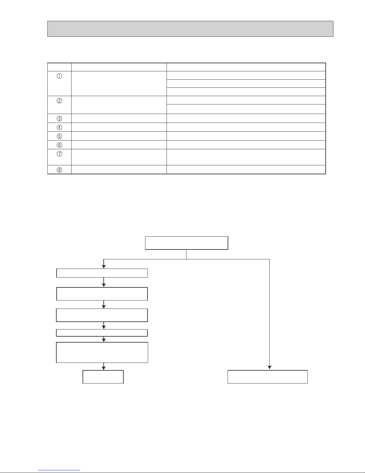
(1) Flowchart
[5] Service tools
Use the below service tools as exclusive tools for R32 refrigerant.
No. Tool name Specifications
Gauge manifold · Only for R32
· Use the existing fitting
specifications
. (UNF1/2)
· Use high-tension side pressure of 5.3MPa·G or over.
Charge hose · Only for R32
· Use pressure performance of 5.09MPa·G or over.
Electronic scale
—
Gas leak detector
· Use the detector for R134a, R407C, R410a or R32.
Adaptor for reverse flow check
· Attach on vacuum pump.
Refrigerant charge base
—
Refrigerant cylinder · Only for R32
· Cylinder with syphon
Refrigerant recovery equipment
—
• Refer to the fl owchart below to determine if the existing pipes can be used and if it is necessary to use a fi lter dryer.
• If the diameter of the existing pipes is different from the specifi ed diameter, refer to technological data materials to confi rm if
the pipes can be used.
Perform the airtight test, vacuum air purging,
additional refrigerant charging (if necessary),
and gas leak check.
Measure the existing pipe thickness and
check for damage.
The existing pipe thickness meets specifi ca-
tions and the pipes are not damaged.
Check if the existing air conditioner can operate.
After operating the cooling system for about 30
minutes, perform pump down work.
Disconnect the existing air conditioner from the
pipes.
Connect the new air conditioner.
Test run
The existing pipes cannot be reused.
Use new pipes.
Note:
If the existing air conditioner cannot operate, use a
refrigerant recovery device to collect the refrigerant.
Use new pipes for MXZ-3F/4F models.
The existing pipe thickness does not meet
specifi cations or the pipes are damaged.
OBH790
10
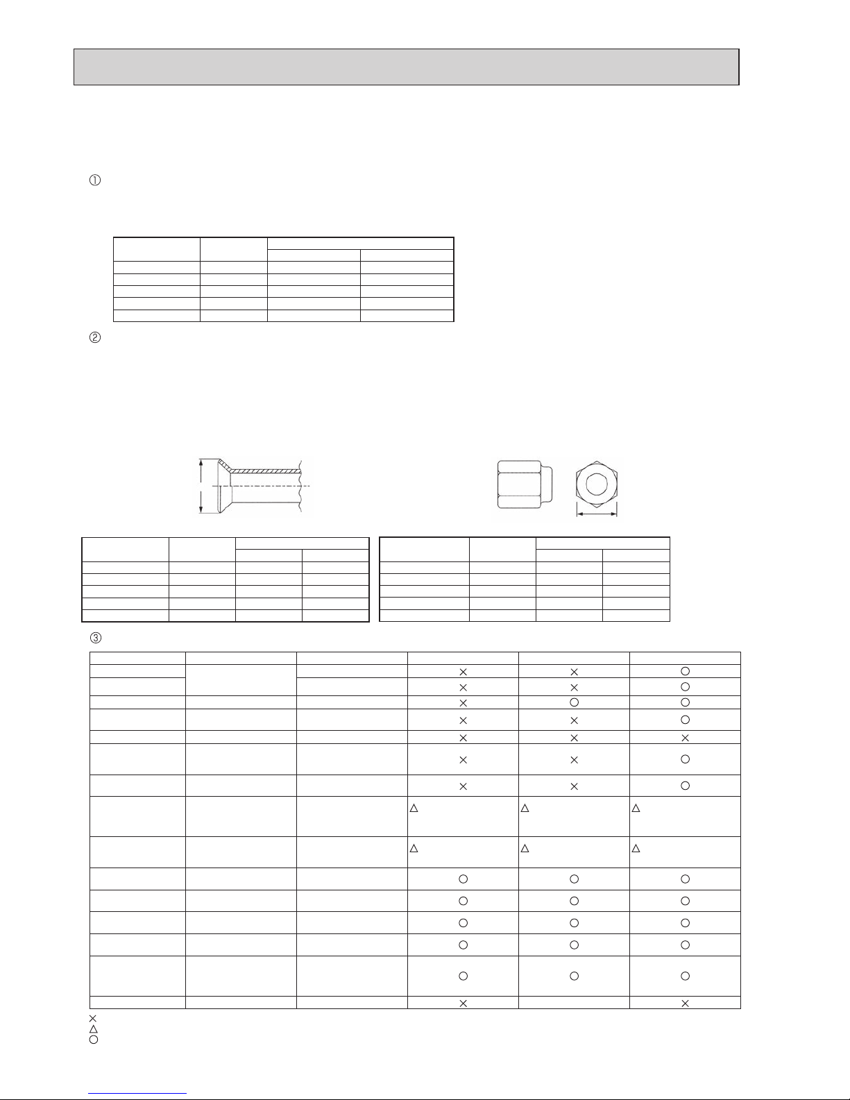
(2) Cautions for refrigerant piping work
New refrigerant R32 is adopted for replacement inverter series. Although the refrigerant piping work for R32 is same as for
R22, exclusive tools are necessary so as not to mix with different kind of refrigerant. Furthermore as the working pressure
of R32 is 1.6 times higher than that of R22, their sizes of flared sections and flare nuts are different.
Thickness of pipes
Because the working pressure of R32 is higher compared to R22, be sure to use refrigerant piping with thickness shown
below. (Never use pipes of 0.7 mm or below.)
Dimensions of flare cutting and flare nut
The component molecules in HFC refrigerant are smaller compared to conventional refrigerants. In addition to that, R32
is a refrigerant, which has higher risk of leakage because its working pressure is higher than that of other refrigerants.
Therefore, to enhance airtightness and strength, flare cutting dimension of copper pipe for R32 has been specified separately from the dimensions for other refrigerants as shown below. The dimension B of flare nut for R32 also has partly
been changed to increase strength as shown below. Set copper pipe correctly referring to copper pipe flaring dimensions
for R32 below. For 1/2 and 5/8 inch pipes, the dimension B changes.
Use torque wrench corresponding to each dimension.
Tools for R32 (The following table shows whether conventional tools can be used or not.)
1/4
3/8
1/2
5/8
3/4
6.35
9.52
12.70
15.88
19.05
0.8
0.8
0.8
1.0
—
0.8
0.8
0.8
1.0
1.0
Nominal
dimensions(inch)
Diagram below: Piping diameter and thickness
Outside
diameter
(mm)
Thickness
(mm)
R32/R410a R22
1/4
3/8
1/2
5/8
3/4
6.35
9.52
12.70
15.88
19.05
9.1
13.2
16.6
19.7
—
9.0
13.0
16.2
19.4
23.3
Nominal
dimensions(inch)
Flare cutting dimensions
Outside
diameter(mm)
R32/R410a R22
Dimension A
( )
+0
-0.4
(mm)
1/4
3/8
1/2
5/8
3/4
6.35
9.52
12.70
15.88
19.05
17.0
22.0
26.0
29.0 *
—
17.0
22.0
24.0
27.0
36.0
Nominal
dimensions(inch)
Flare nut dimensions
Outside
diameter(mm)
Dimension B
R32/R410a
* 36.0mm for
indoor unit
of RP100,
125 and 140
R22
(mm)
Dimension A
Dimension B
Tools and materials Use R32 tools Can R22 tools be used?
Can R407C tools be used?
Can R410a tools be used?
Gauge manifold Air purge, refrigerant
charge and operation
check
Tool exclusive for R32
Charge hose
Tool exclusive for R32
Gas leak detector Gas leak check Tool for HFC refrigerant
Refrigerant recovery
equipment
Refrigerant recovery Tool exclusive for R32
Refrigerant cylinder Refrigerant charge Tool exclusive for R32
Safety charger
Prevent compressor malfunction
when charging refrigerant by
spraying liquid refrigerant
Tool exclusive for R32
Charge valve
Prevent gas from blowing out
when detaching charge hose
Tool exclusive for R32
Vacuum pump
Vacuum drying and air
purge
Tools for other refrigerants
can be used if equipped
with adapter for reverse
fl ow check
(Usable if equipped with
adapter for reverse
fl ow)
(Usable if equipped with
adapter for reverse
fl ow)
(Usable if equipped with
adapter for reverse
fl ow)
Flare tool
Flaring work of piping
Tools for other refrigerants
can be used by adjusting
fl aring dimension
(Usable by adjusting
fl aring dimension)
(Usable by adjusting
fl aring dimension)
(Usable by adjusting
fl aring dimension)
Bender
Bend the pipes
Tools for other refrigerants
can be used
Pipe cutter
Cut the pipes
Tools for other refrigerants
can be used
Welder and nitrogen
gas cylinder
Weld the pipes
Tools for other refrigerants
can be used
Refrigerant charging
scale
Refrigerant charge
Tools for other refrigerants
can be used
Vacuum gauge or
thermistor vacuum
gauge and vacuum
valve
Check the degree of vacuum.
(Vacuum valve prevents back
fl ow of oil and refrigerant to
thermistor vacuum gauge)
Tools for other refrigerants
can be used
Charging cylinder Refrigerant charge Tool exclusive for R32 –
: Prepare a new tool. (Use the new tool as the tool exclusive for R32.)
: Tools for other refrigerants can be used under certain conditions.
: Tools for other refrigerants can be used.
OBH790
11
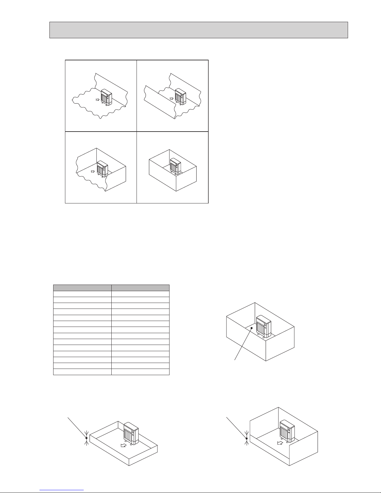
2-4. CHOOSING THE OUTDOOR UNIT INSTALLATION LOCATION
R32 is heavier than air—as well as other refrigerants—
so tends to accumulate at the base (in the vicinity of the
floor). If R32 accumulates around base, it may reach a
flammable concentration in case room is small. To avoid
ignition, maintaining a safe work environment is required
by ensuring appropriate ventilation. If a refrigerant leak is
confirmed in a room or an area where there is insufficient
ventilation, refrain from using of flames until the work
environment can be improved by ensuring appropriate
ventilation.
Install outdoor units in a place where at least one of the
four sides is open, and in a sufficiently large space without depressions.
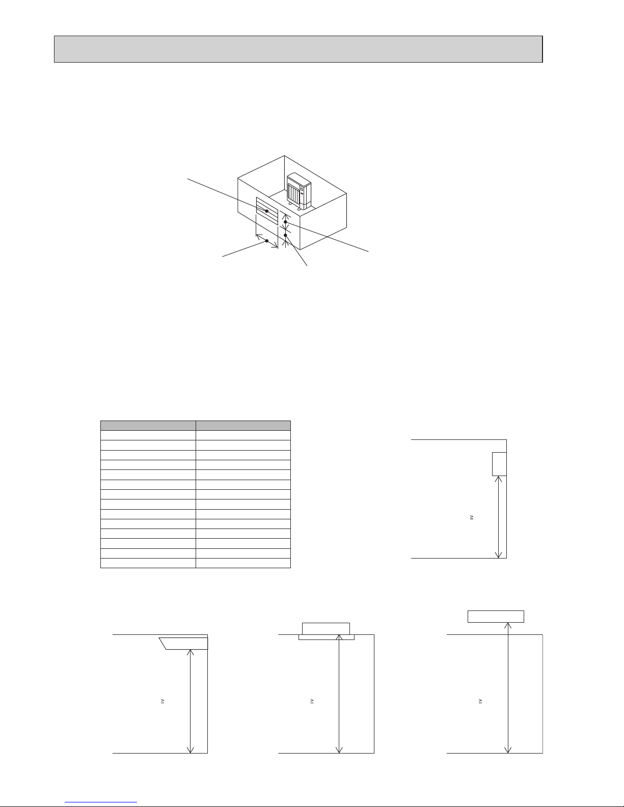
2-5. MINIMUM INSTALLATION AREA
If you unavoidably install a unit in a space where all four sides are blocked or there are depressions, confirm that one of
these situations (A, B or C) is satisfied.
Note: These countermeasures are for keeping safety not for specification guarantee.
A) Secure sufficient installation space (minimum installation area Amin).
Install in a space with an installation area of Amin or more, corresponding to refrigerant quantity M (factory-charged
refrigerant + locally added refrigerant).
B) Install in a space with a depression height of 0.125 [m] or less.
OK OK
OK NG
Amin
Height from the bottom of
0.125 [m] or less
Height from the bottom of
0.125 [m] or less
M [kg] Amin [m²]
1.0 12
1.5 17
2.0 23
2.5 28
3.0 34
3.5 39
4.0 45
4.5 50
5.0 56
5.5 62
6.0 67
6.5 73
7.0 78
7.5 84
OBH790
12
C) Create an appropriate ventilation open area.
Make sure that the width of the open area is 0.9 [m] or more and the height of the open area is 0.15 [m] or more.
However, the height from the bottom of the installation space to the bottom edge of the open area should be 0.125 [m]
or less.
Open area should be 75% or more opening.
■ Indoor units
Install in a room with a floor area of Amin or more, corresponding to refrigerant quantity M (factory-charged refrigerant + locally added refrigerant).
* For the factory-charged refrigerant amount, refer to the spec nameplate or installation manual.
For the amount to be added locally, refer to the installation manual.
Install the indoor unit so that the height from the floor to the bottom of the indoor unit is h0;
for wall mounted: 1.8 m or more;
for ceiling suspended, cassette and ceiling concealed: 2.2 m or more.
* There are restrictions in installation height for each model, so read the installation manual for the particular unit.
75% or more opening
Width W 0.9 [m] or more
Height from the bottom
0.125 [m] or less
Height H 0.15 [m] or more
M [kg] Amin [m²]
1.0 3
1.5 4.5
2.0 6
2.5 7.5
3.0 9
3.5 12
4.0 15.5
4.5 20
5.0 24
5.5 29
6.0 35
6.5 41
7.0 47
7.5 54
Wall mounted
h0
1.8 [m]
Ceiling concealedCassetteCeiling suspended
h0 2.2 [m]h0 2.2 [m]h0 2.2 [m]
OBH790
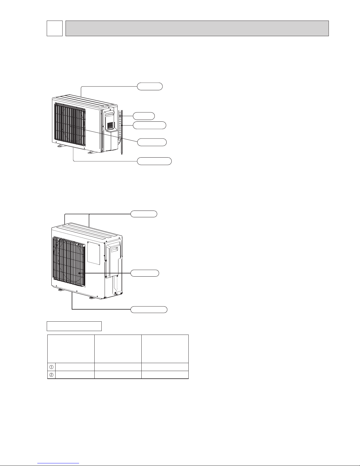
13
PART NAMES AND FUNCTIONS
3
ACCESSORIES
Model
MXZ-2F33VF
MXZ-2F42VF
MXZ-2F53VF
MXZ-3F54VF
MXZ-3F68VF
MXZ-4F72VF
Drain socket 1 1
Drain cap - 2
Air outlet
Drain outlet
Air inlet
(Back and side)
MXZ-3F54VF
MXZ-3F68VF
MXZ-4F72VF
MXZ-2F33VF
MXZ-2F42VF
MXZ-2F53VF
MXZ-2F53VFH
Air inlet
Air outlet
Drain outlet
Piping
Drain hose
(Back and side)
OBH790
14
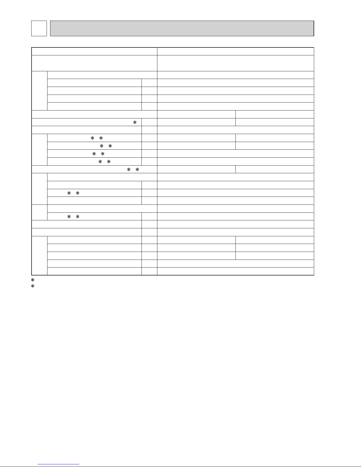
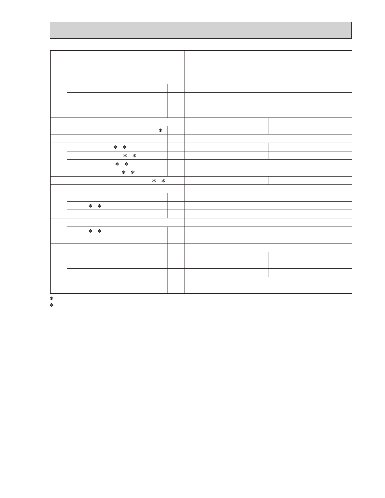
SPECIFICATION
4
Outdoor model MXZ-2F33VF
Outdoor unit power supply
Single phase
220 - 230 - 240 V, 50 Hz
System
Indoor units number 2
Piping total length m Max. 20
Connecting pipe length m Max. 15
Height difference (Indoor ~ Outdoor) m Refer to 8 REFRIGERANT SYSTEM DIAGRAM.
Height difference (Indoor ~ Indoor) m Refer to 8 REFRIGERANT SYSTEM DIAGRAM.
Function Cooling Heating
Capacity Rated frequency (Min.-Max.)
2 kW 3.3 (1.1 - 3.8) 4.0 (1.0 - 4.1)
Breaker capacity A 15
Electrical
data
Power input (Total) 1, 2 W 850 910
Running current (Total)
1, 2 A 4.3 - 4.1 - 3.9 4.6 - 4.4 - 4.2
Power factor (Total)
1, 2% 90
Starting current (Total)
1, 2 A 4.6
Coeffi cient of performance (C.O.P) (Total)
1, 2 3.88 4.40
Compressor
Model KVB073FYXMC
Output W 470
Current
1, 2 A 3.8
Refrigeration oil (Model) L 0.27 (FW68S)
Fan
motor
Model RC0J50-FA
Current
1, 2 A 0.35
Dimensions W x H x D mm 800 x 550 x 285
Weight kg 33
Special
remarks
Air fl ow (Rated) m3 /h 1,890 1,938
Sound level (Rated) dB(A) 49 50
Fan speed (Rated) rpm 860 880
Pre-charged refrigerant quantity (R32) kg 1.0
Max refrigerant quantity (R32) kg 1.0
1 Measured under rated operating frequency.
2 When connected with indoor units below.
MSZ-AP15VF + MSZ-LN18VG
NOTE: Test conditions are based on ISO 5151. (Refrigerant piping length (one way): 5 m)
COOLING INDOOR Dry-bulb temperature 27.0 °C Wet-bulb temperature 19.0 °C
OUTDOOR Dry-bulb temperature 35.0 °C Wet-bulb temperature 24.0 °C
HEATING INDOOR Dry-bulb temperature 20.0 °C
OUTDOOR Dry-bulb temperature 7.0 °C Wet-bulb temperature 6.0 °C
OBH790

15
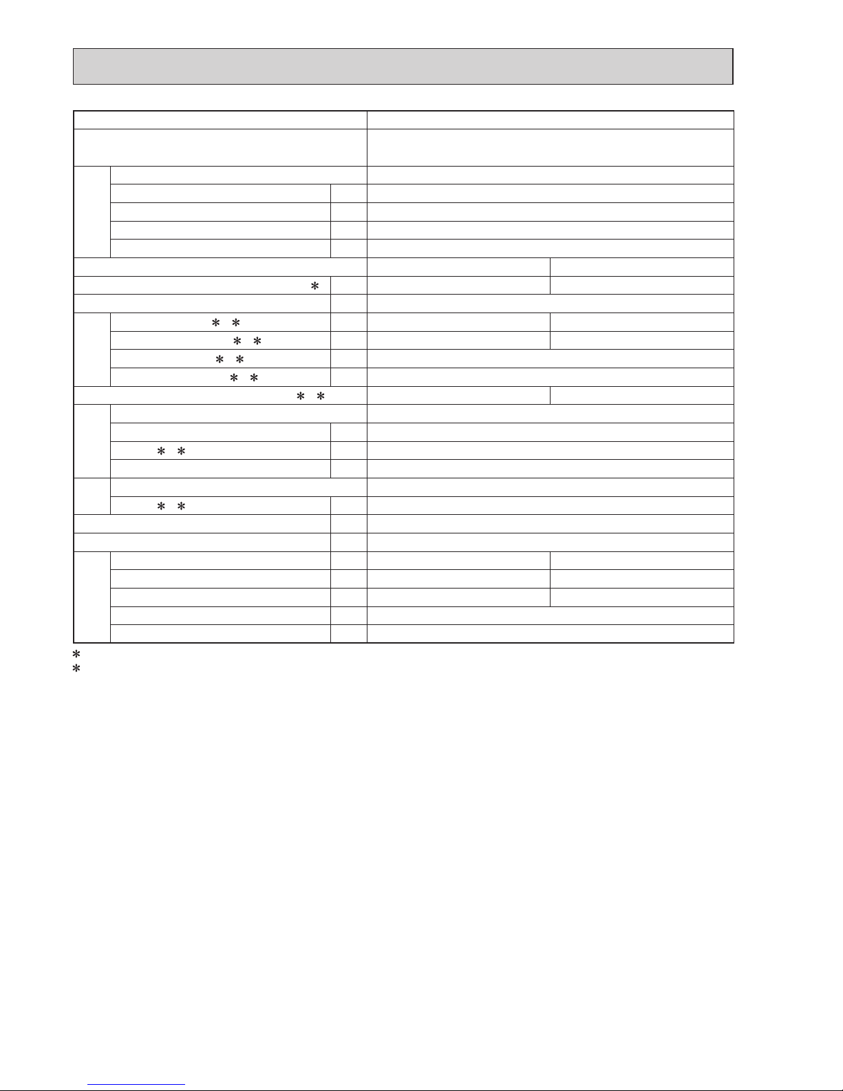
Outdoor model MXZ-2F42VF
Outdoor unit power supply
Single phase
220 - 230 - 240 V, 50 Hz
System
Indoor units number 2
Piping total length m Max. 30
Connecting pipe length m Max. 20
Height difference (Indoor ~ Outdoor) m Refer to 8 REFRIGERANT SYSTEM DIAGRAM.
Height difference (Indoor ~ Indoor) m Refer to 8 REFRIGERANT SYSTEM DIAGRAM.
Function Cooling Heating
Capacity Rated frequency (Min.-Max.)
2 kW 4.2 (1.1 - 4.4) 4.5 (1.0 - 4.8)
Breaker capacity A 15
Electrical
data
Power input (Total) 1, 2 W 980 880
Running current (Total)
1, 2 A 4.9 - 4.7 - 4.5 4.4 - 4.3 - 4.1
Power factor (Total)
1, 2% 90
Starting current (Total)
1, 2 A 7.6
Coeffi cient of performance (C.O.P) (Total)
1, 2 4.29 5.11
Compressor
Model SVB130FBBMT
Output W 1,100
Current
1, 2 A 3.99
Refrigeration oil (Model) L 0.35 (FW68S)
Fan
motor
Model RC0J50-FA
Current
1, 2 A 0.35
Dimensions W x H x D mm 800 x 550 x 285
Weight kg 37
Special
remarks
Air fl ow (Rated) m3 /h 1,704 2,010
Sound level (Rated) dB(A) 44 50
Fan speed (Rated) rpm 780 910
Pre-charged refrigerant quantity (R32) kg 1.2
Max refrigerant quantity (R32) kg 1.2
1 Measured under rated operating frequency.
2 When connected with indoor units below.
MSZ-LN18VG + MSZ-LN25VG
NOTE: Test conditions are based on ISO 5151. (Refrigerant piping length (one way): 5 m)
COOLING INDOOR Dry-bulb temperature 27.0 °C Wet-bulb temperature 19.0 °C
OUTDOOR Dry-bulb temperature 35.0 °C Wet-bulb temperature 24.0 °C
HEATING INDOOR Dry-bulb temperature 20.0 °C
OUTDOOR Dry-bulb temperature 7.0 °C Wet-bulb temperature 6.0 °C
OBH790

16
Outdoor model MXZ-2F53VF MXZ-2F53VFH
Outdoor unit power supply
Single phase
220 - 230 - 240 V, 50 Hz
System
Indoor units number 2
Piping total length m Max. 30
Connecting pipe length m Max. 20
Height difference (Indoor ~ Outdoor) m Refer to 8 REFRIGERANT SYSTEM DIAGRAM.
Height difference (Indoor ~ Indoor) m Refer to 8 REFRIGERANT SYSTEM DIAGRAM.
Function Cooling Heating
Capacity Rated frequency (Min.-Max.)
2 kW 5.3 (1.1 - 5.6) 6.4 (1.0 - 7.0)
Breaker capacity A 15
Electrical
data
Power input (Total) 1, 2 W 1,400 1,560
Running current (Total)
1, 2 A 6.5 - 6.2 - 6.0 7.5 - 7.1 - 6.8
Power factor (Total)
1, 2 % 97.5 95
Starting current (Total)
1, 2 A 7.6
Coeffi cient of performance (C.O.P) (Total)
1, 2 3.79 4.10
Compressor
Model SVB130FBBMT
Output W 1,400
Current
1, 2 A 6.59
Refrigeration oil (Model) L 0.35 (FW68S)
Fan
motor
Model RC0J50-FA
Current
1, 2 A 0.35
Dimensions W x H x D mm 800 x 550 x 285
Weight kg MXZ-2F53VF: 37 MXZ-2F53VFH: 38
Special
remarks
Air fl ow (Rated) m3 /h 1,962 2,082
Sound level (Rated) dB(A) 46 51
Fan speed (Rated) rpm 890 940
Pre-charged refrigerant quantity (R32) kg 1.2
Max refrigerant quantity (R32) kg 1.2
1 Measured under rated operating frequency.
2 When connected with indoor units below.
MSZ-LN18VG + MSZ-LN35VG
NOTE: Test conditions are based on ISO 5151. (Refrigerant piping length (one way): 5 m)
COOLING INDOOR Dry-bulb temperature 27.0 °C Wet-bulb temperature 19.0 °C
OUTDOOR Dry-bulb temperature 35.0 °C Wet-bulb temperature 24.0 °C
HEATING INDOOR Dry-bulb temperature 20.0 °C
OUTDOOR Dry-bulb temperature 7.0 °C Wet-bulb temperature 6.0 °C
OBH790

17
Outdoor model MXZ-3F54VF
Outdoor unit power supply
Single phase
220 - 230 - 240 V, 50 Hz
System
Indoor units number 2 to 3
Piping total length m Max. 50
Connecting pipe length m Max. 25
Height difference (Indoor ~ Outdoor) m Refer to 8 REFRIGERANT SYSTEM DIAGRAM.
Height difference (Indoor ~ Indoor) m Refer to 8 REFRIGERANT SYSTEM DIAGRAM.
Function Cooling Heating
Capacity Rated frequency (Min.-Max.)
2 kW 5.4 (2.9 - 6.8) 7.0 (2.6 - 9.0)
Breaker capacity A 25
Electrical
data
Power input (Total) 1, 2 W 1,320 1,400
Running current (Total)
1, 2 A 6.0 - 5.7 - 5.5 6.4 - 6.1 - 5.9
Power factor (Total)
1, 2% 99
Starting current (Total)
1, 2 A 6.7
Coeffi cient of performance (C.O.P) (Total)
1, 2 4.09 5.00
Compressor
Model SVB130FBBM1T
Output W 1,400
Current
1, 2 A 5.06
Refrigeration oil (Model) L 0.6 (FW68S)
Fan
motor
Model SIC-82FX-F764-1
Current
1, 2 A 0.5
Dimensions W x H x D mm 840 x 710 x 330
Weight kg 57
Special
remarks
Air fl ow (Rated) m3 /h 1,860 1,632
Sound level (Rated) dB(A) 46 50
Fan speed (Rated) rpm 600 560
Pre-charged refrigerant quantity (R32) kg 1.4
Max refrigerant quantity (R32) kg 2.4
1 Measured under rated operating frequency.
2 When connected with indoor units below.
MSZ-LN18VG + MSZ-LN18VG + MSZ-LN18VG
NOTE: Test conditions are based on ISO 5151. (Refrigerant piping length (one way): 5 m)
COOLING INDOOR Dry-bulb temperature 27.0 °C Wet-bulb temperature 19.0 °C
OUTDOOR Dry-bulb temperature 35.0 °C Wet-bulb temperature 24.0 °C
HEATING INDOOR Dry-bulb temperature 20.0 °C
OUTDOOR Dry-bulb temperature 7.0 °C Wet-bulb temperature 6.0 °C
OBH790
18
Outdoor model MXZ-3F68VF
Outdoor unit power supply
Single phase
220 - 230 - 240 V, 50 Hz
System
Indoor units number 2 to 3
Piping total length m Max. 60
Connecting pipe length m Max. 25
Height difference (Indoor ~ Outdoor) m Refer to 8 REFRIGERANT SYSTEM DIAGRAM.
Height difference (Indoor ~ Indoor) m Refer to 8 REFRIGERANT SYSTEM DIAGRAM.
Function Cooling Heating
Capacity Rated frequency (Min.-Max.)
2 kW 6.8 (2.9 - 8.4) 8.6 (2.6 - 10.6)
Breaker capacity A 25
Electrical
data
Power input (Total) 1, 2 W 1,840 1,910
Running current (Total)
1, 2 A 8.4 - 8.0 - 7.7 8.8 - 8.4 - 8.0
Power factor (Total)
1, 2% 99
Starting current (Total)
1, 2 A 10.1
Coeffi cient of performance (C.O.P) (Total)
1, 2 3.70 4.50
Compressor
Model SVB172FCKM1T
Output W 1,800
Current
1, 2 A 8.58
Refrigeration oil (Model) L 0.6 (FW68S)
Fan
motor
Model SIC-82FX-F764-1
Current
1, 2 A 0.5
Dimensions W x H x D mm 840 x 710 x 330
Weight kg 57
Special
remarks
Air fl ow (Rated) m3 /h 2,124 2,376
Sound level (Rated) dB(A) 48 53
Fan speed (Rated) rpm 650 700
Pre-charged refrigerant quantity (R32) kg 1.4
Max refrigerant quantity (R32) kg 2.4
1 Measured under rated operating frequency.
2 When connected with indoor units below.
MSZ-LN18VG + MSZ-LN25VG + MSZ-LN25VG
NOTE: Test conditions are based on ISO 5151. (Refrigerant piping length (one way): 5 m)
COOLING INDOOR Dry-bulb temperature 27.0 °C Wet-bulb temperature 19.0 °C
OUTDOOR Dry-bulb temperature 35.0 °C Wet-bulb temperature 24.0 °C
HEATING INDOOR Dry-bulb temperature 20.0 °C
OUTDOOR Dry-bulb temperature 7.0 °C Wet-bulb temperature 6.0 °C
OBH790
19
Outdoor model MXZ-4F72VF
Outdoor unit power supply
Single phase
220 - 230 - 240 V, 50 Hz
System
Indoor units number 2 to 4
Piping total length m Max. 60
Connecting pipe length m Max. 25
Height difference (Indoor ~ Outdoor) m Refer to 8 REFRIGERANT SYSTEM DIAGRAM.
Height difference (Indoor ~ Indoor) m Refer to 8 REFRIGERANT SYSTEM DIAGRAM.
Function Cooling Heating
Capacity Rated frequency (Min.-Max.)
2 kW 7.2 (3.7 - 8.8) 8.6 (3.4 - 10.7)
Breaker capacity A 25
Electrical
data
Power input (Total) 1, 2 W 1,850 1,870
Running current (Total)
1, 2 A 8.5 - 8.1 - 7.8 8.6 - 8.2 - 7.9
Power factor (Total)
1, 2% 99
Starting current (Total)
1, 2 A 10.1
Coeffi cient of performance (C.O.P) (Total)
1, 2 3.89 4.60
Compressor
Model SVB172FCKM1T
Output W 2,000
Current
1, 2 A 6.98
Refrigeration oil (Model) L 0.6 (FW68S)
Fan
motor
Model SIC-82FX-F764-1
Current
1, 2 A 0.5
Dimensions W x H x D mm 840 x 710 x 330
Weight kg 58
Special
remarks
Air fl ow (Rated) m3 /h 2,124 2,562
Sound level (Rated) dB(A) 48 54
Fan speed (Rated) rpm 650 740
Pre-charged refrigerant quantity (R32) kg 1.4
Max refrigerant quantity (R32) kg 2.4
1 Measured under rated operating frequency.
2 When connected with indoor units below.
MSZ-LN18VG + MSZ-LN18VG + MSZ-LN18VG + MSZ-LN18VG
NOTE: Test conditions are based on ISO 5151. (Refrigerant piping length (one way): 5 m)
COOLING INDOOR Dry-bulb temperature 27.0 °C Wet-bulb temperature 19.0 °C
OUTDOOR Dry-bulb temperature 35.0 °C Wet-bulb temperature 24.0 °C
HEATING INDOOR Dry-bulb temperature 20.0 °C
OUTDOOR Dry-bulb temperature 7.0 °C Wet-bulb temperature 6.0 °C
OBH790
20
NOISE CRITERIA CURVES
5
90
80
70
60
50
40
30
20
10
63 125 250 500 1000 2000 4000 8000
NC-60
NC-50
NC-40
NC-30
NC-20
NC-70
OCTAVE BAND SOUND PRESSURE LEVEL, dB re 0.0002 MICRO BAR
BAND CENTER FREQUENCIES, Hz
APPROXIMATE
THRESHOLD OF
HEARING FOR
CONTINUOUS
NOISE
CoolingHigh
FUNCTION
FAN SPEED
HeatingHigh
44
SPL(dB(A))50LINE
90
80
70
60
50
40
30
20
10
63 125 250 500 1000 2000 4000 8000
NC-60
NC-50
NC-40
NC-30
NC-20
NC-70
OCTAVE BAND SOUND PRESSURE LEVEL, dB re 0.0002 MICRO BAR
BAND CENTER FREQUENCIES, Hz
APPROXIMATE
THRESHOLD OF
HEARING FOR
CONTINUOUS
NOISE
CoolingHigh
FUNCTION
FAN SPEED
HeatingHigh
49
SPL(dB(A))50LINE
90
80
70
60
50
40
30
20
10
63 125 250 500 1000 2000 4000 8000
NC-60
NC-50
NC-40
NC-30
NC-20
NC-70
OCTAVE BAND SOUND PRESSURE LEVEL, dB re 0.0002 MICRO BAR
BAND CENTER FREQUENCIES, Hz
APPROXIMATE
THRESHOLD OF
HEARING FOR
CONTINUOUS
NOISE
CoolingHigh
FUNCTION
FAN SPEED
HeatingHigh
46
SPL(dB(A))51LINE
MXZ-2F53VF
MXZ-2F53VFH
MXZ-2F33VF MXZ-2F42VF
OBH790
21
OUTDOOR UNIT
MICROPHONE
1m
Test conditions
Cooling :Dry-bulb temperature 35.0°C Wet-bulb temperature 24.0°C
Heating :Dry-bulb temperature 7.0°C Wet-bulb temperature 6.0°C
90
80
70
60
50
40
30
20
10
63 125 250 500 1000 2000 4000 8000
NC-60
NC-50
NC-40
NC-30
NC-20
NC-70
OCTAVE BAND SOUND PRESSURE LEVEL, dB re 0.0002 MICRO BAR
BAND CENTER FREQUENCIES, Hz
APPROXIMATE
THRESHOLD OF
HEARING FOR
CONTINUOUS
NOISE
CoolingHigh
FUNCTION
FAN SPEED
HeatingHigh
46
SPL(dB(A))50LINE
90
80
70
60
50
40
30
20
10
63 125 250 500 1000 2000 4000 8000
NC-60
NC-50
NC-40
NC-30
NC-20
NC-70
OCTAVE BAND SOUND PRESSURE LEVEL, dB re 0.0002 MICRO BAR
BAND CENTER FREQUENCIES, Hz
APPROXIMATE
THRESHOLD OF
HEARING FOR
CONTINUOUS
NOISE
CoolingHigh
FUNCTION
FAN SPEED
HeatingHigh
48
SPL(dB(A))53LINE
90
80
70
60
50
40
30
20
10
63 125 250 500 1000 2000 4000 8000
NC-60
NC-50
NC-40
NC-30
NC-20
NC-70
OCTAVE BAND SOUND PRESSURE LEVEL, dB re 0.0002 MICRO BAR
BAND CENTER FREQUENCIES, Hz
APPROXIMATE
THRESHOLD OF
HEARING FOR
CONTINUOUS
NOISE
CoolingHigh
FUNCTION
FAN SPEED
HeatingHigh
48
SPL(dB(A))54LINE
MXZ-3F54VF MXZ-3F68VF
MXZ-4F72VF
OBH790
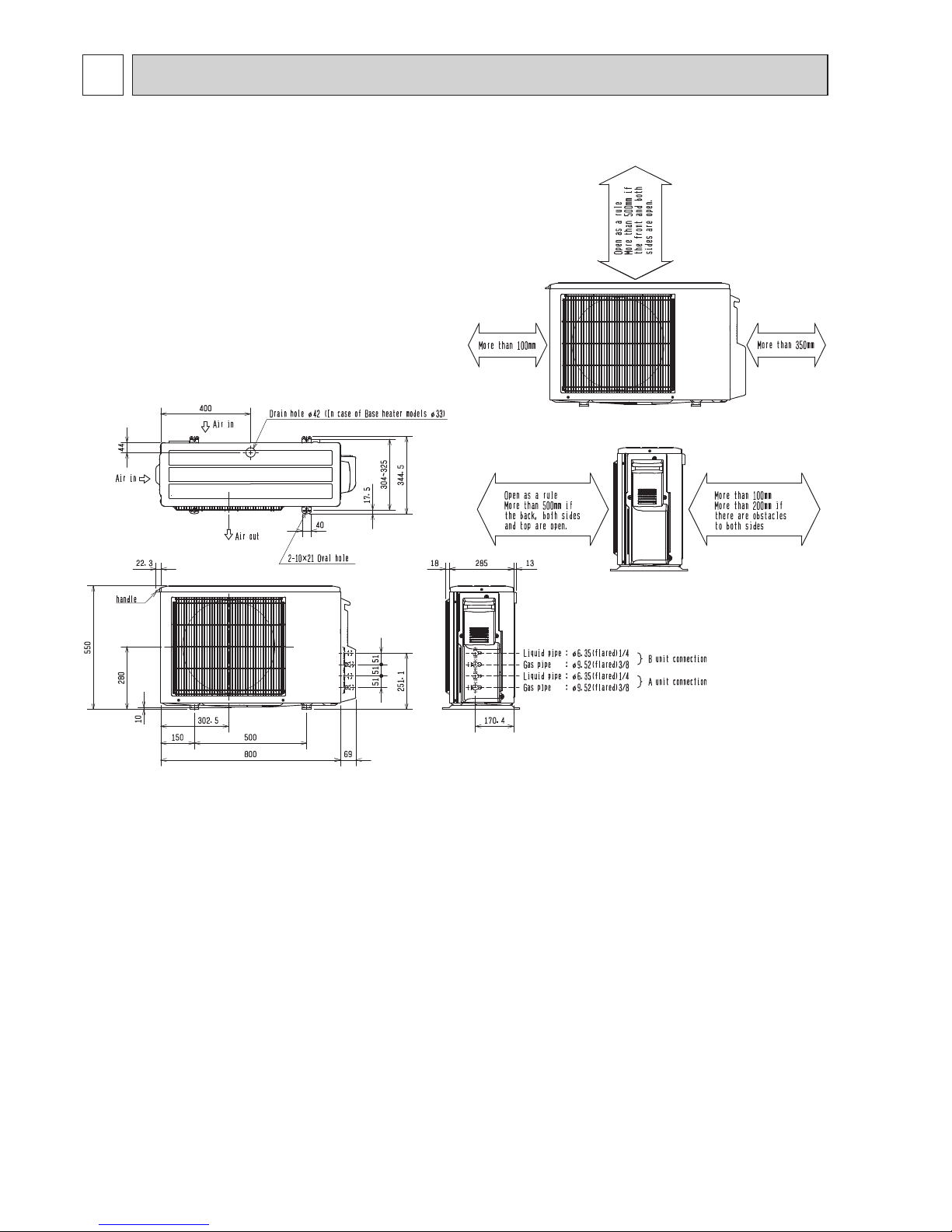
22
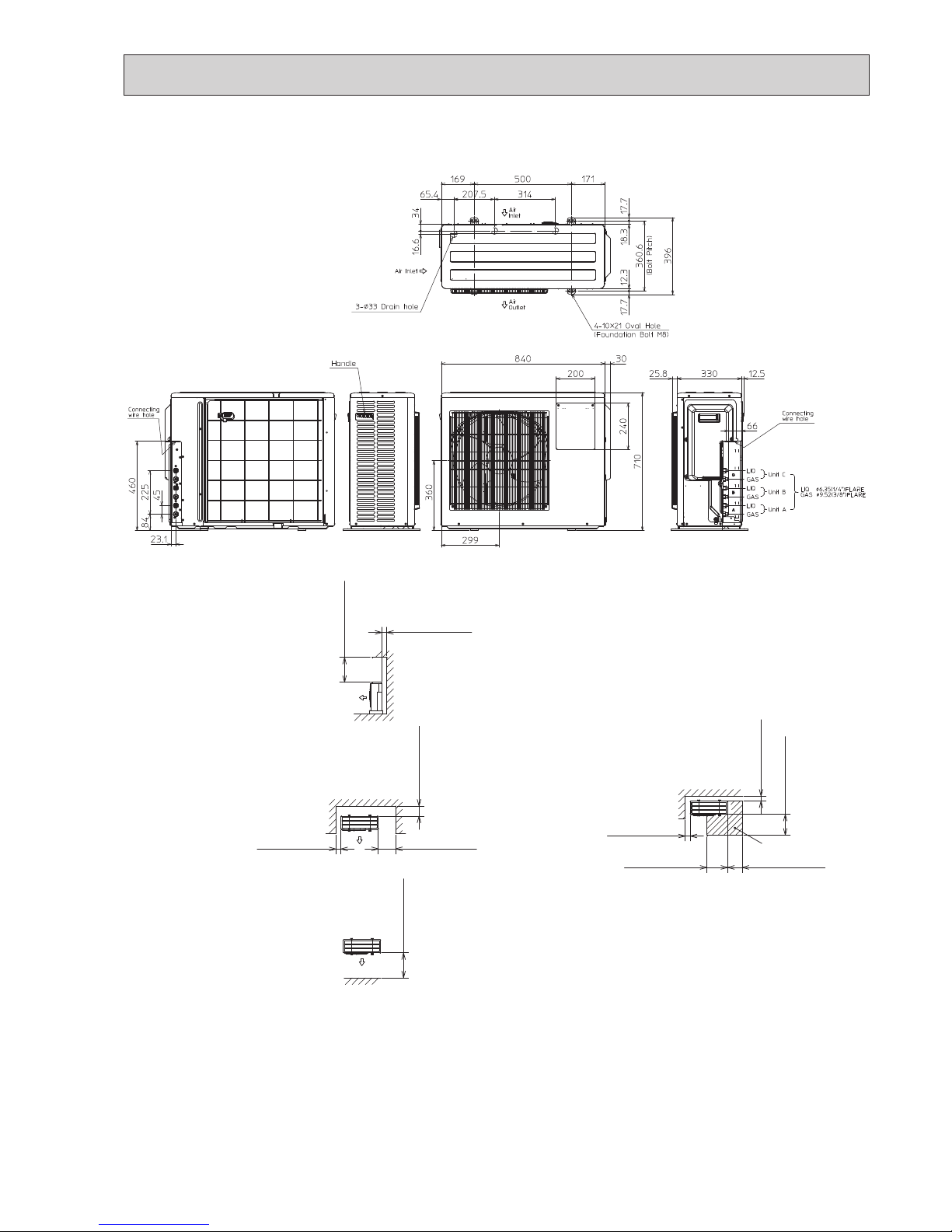
OUTLINES AND DIMENSIONS
6
MXZ-2F33VF MXZ-2F42VF MXZ-2F53VF MXZ-2F53VFH
Unit: mm
OBH790
23
1.Installation space
Note : Leave front and both sides
free of obstruction.
Note : Leave rear, overhead and
both sides free of obstruction.
500 or more
100 or more
Note : Leave front and overhead
free of obstruction.
100 or more
350 or more
200 or more
500 or more
2.Service space
100 or more
500 or more
350 or more
350 or more
100 or more
Service space
MXZ-3F54VF MXZ-3F68VF
Unit: mm
OBH790
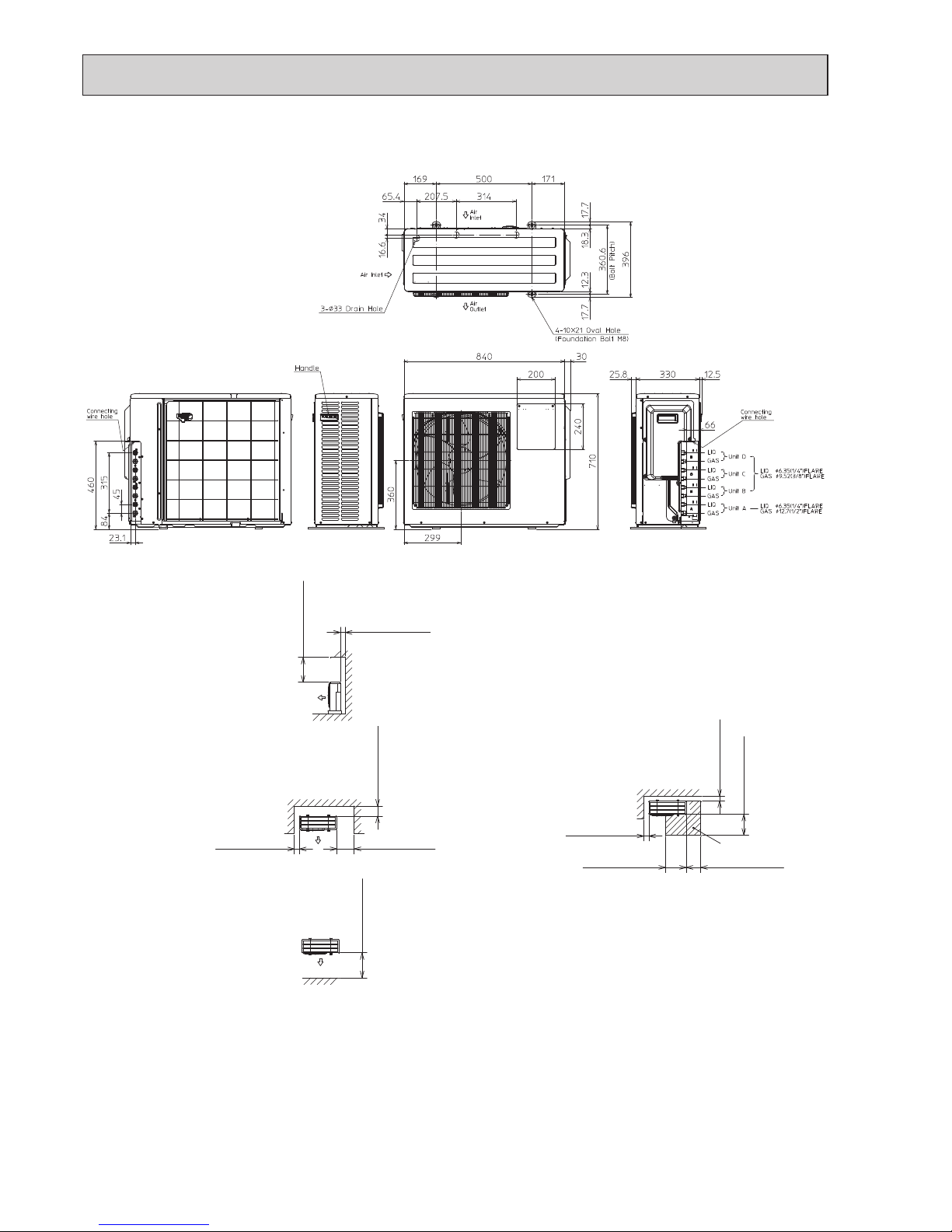
24
1.Installation space
Note : Leave front and both sides
free of obstruction.
Note : Leave rear, overhead and
both sides free of obstruction.
500 or more
100 or more
Note : Leave front and overhead
free of obstruction.
100 or more
350 or more
200 or more
500 or more
2.Service space
100 or more
500 or more
350 or more
350 or more
100 or more
Service space
MXZ-4F72VF
Unit: mm
OBH790
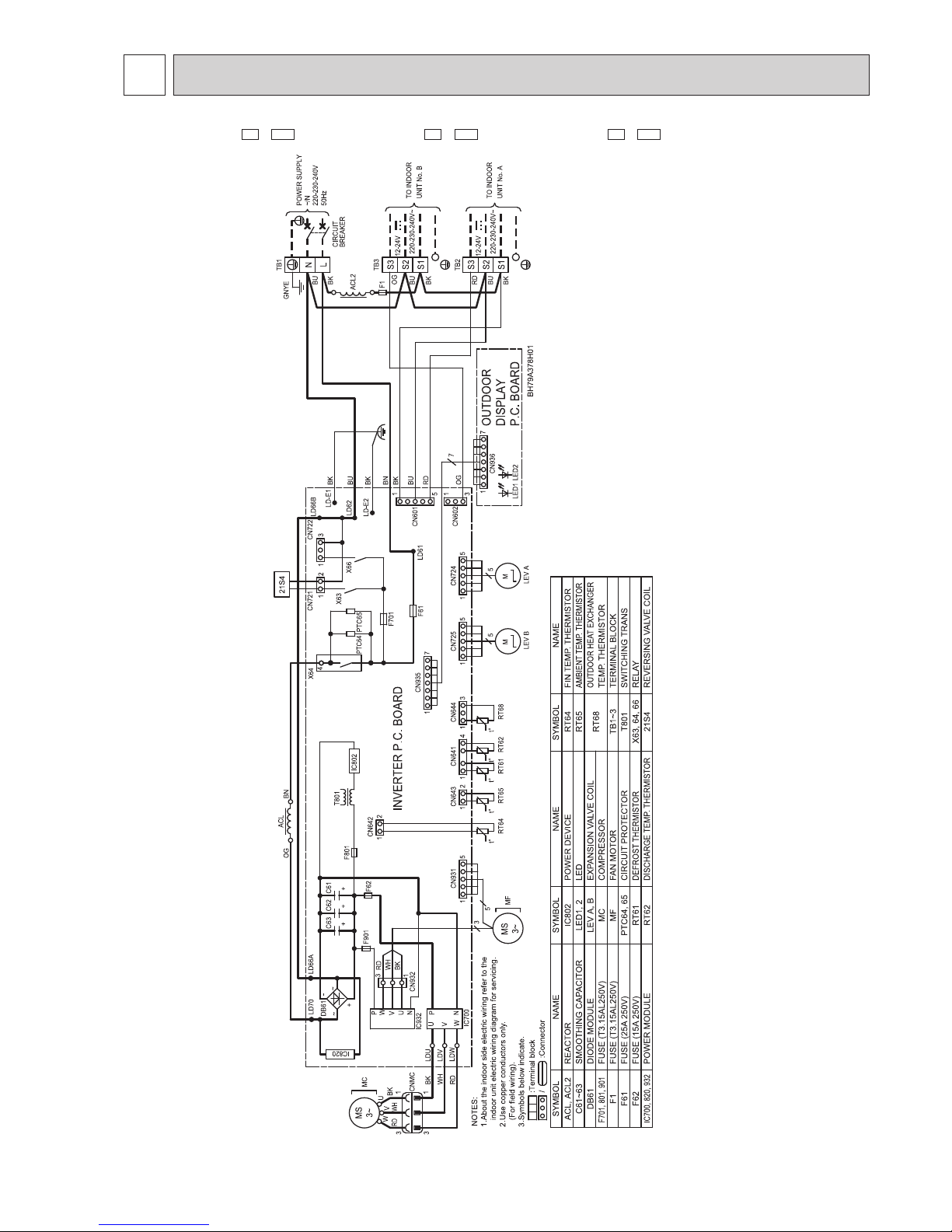
25
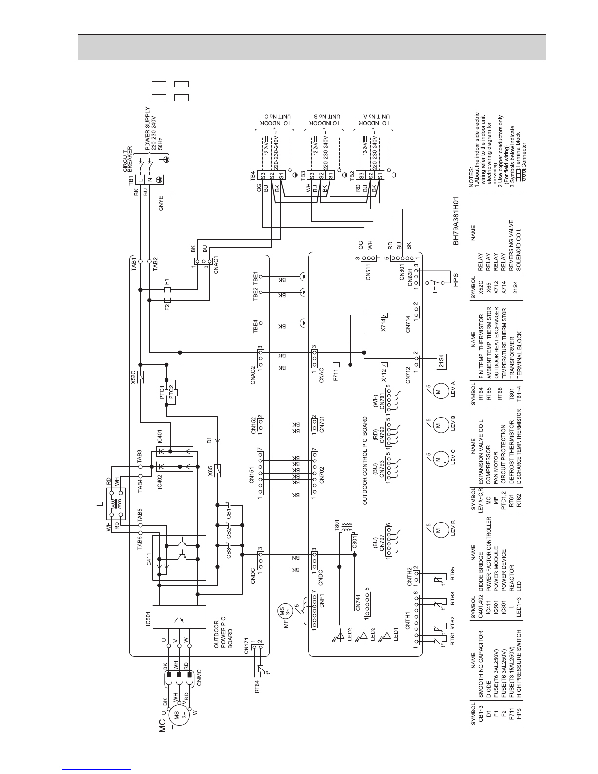
WIRING DIAGRAM
7
MXZ-2F33VF -
E1
,
ET1
MXZ-2F42VF -E1,
ET1
MXZ-2F53VF -
E1, ET1
OBH790
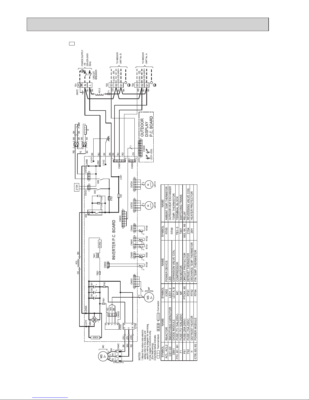
26
MXZ-2F53VFH -
E1
OBH790
27
MXZ-3F54VF -E1,
ET1
MXZ-3F68VF -E1,
ET1
OBH790
28
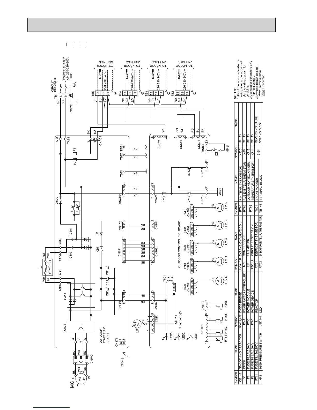
MXZ-4F72VF -E1,
ET1
OBH790
29
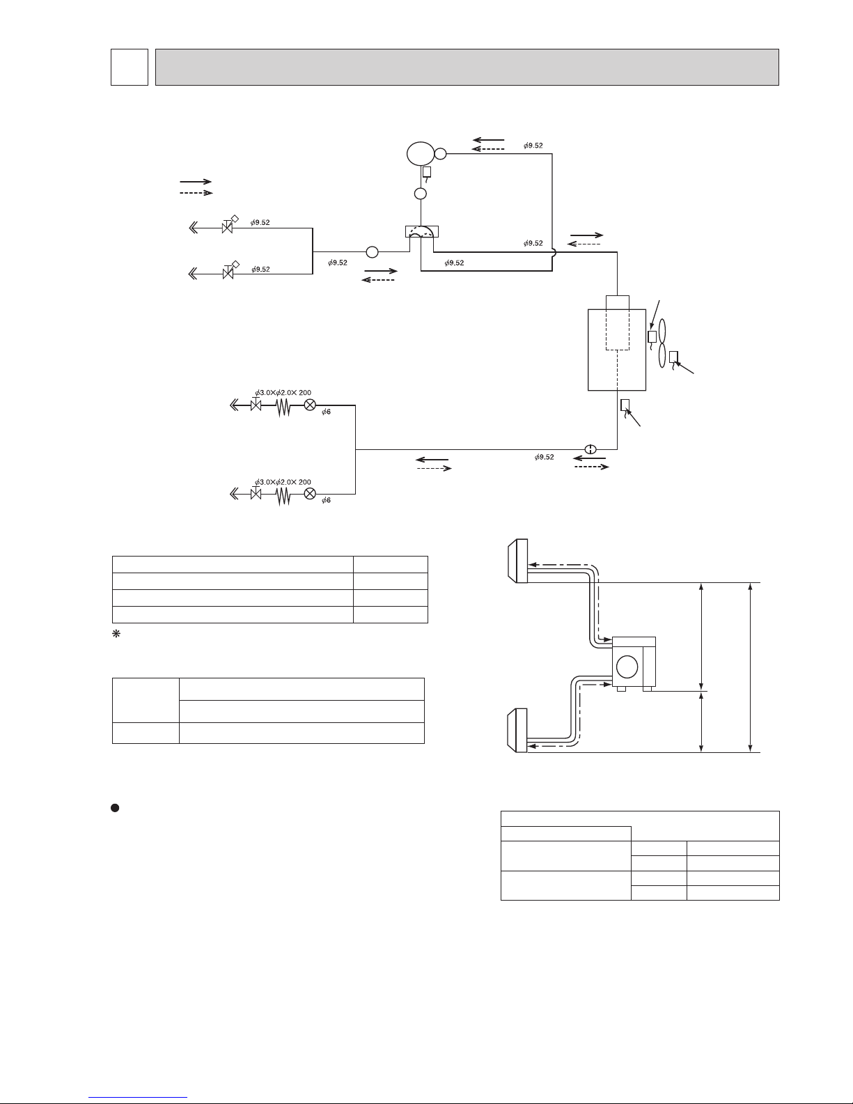
REFRIGERANT SYSTEM DIAGRAM
8
a
b
Outdoor
unit
Indoor
units
10 m
10 m
10 m
Max.
Height
difference
Stop valve
(with strainer #100)
LEV A
LEV B
Compressor
Defrost
thermistor
RT61
Muffler
4-way valve
Indoor unit
A
Indoor unit
B
Indoor unit
A
Indoor unit
B
Capillary tube
Capillary tube
Strainer
#100
Stop valve
(with strainer #100)
R.V. coil
OFF
ON
Refrigerant flow in cooling
Refrigerant flow in heating
Ambient
temperature
thermistor
RT65
Outdoor heat
exchanger
temperature
thermistor
RT68
FAN-OUT
HEX-OUT
Discharge
temperature
thermistor RT62
Stop valve
(with service port)
Stop valve
(with service port)
Sub muffler
UNIT: mm
MXZ-2F33VF
UNIT: mm (inch)
Outdoor unit union diameter
For
Indoor unit A
Liquid 6.35(1/4)
Gas 9.52(3/8)
Indoor unit B
Liquid 6.35(1/4)
Gas 9.52(3/8)
MAX REFRIGERANT PIPING LENGTH
Piping length each indoor unit (a, b) 15 m
Total piping length (a+b) 20 m
Bending point for each unit 15
Total bending point 20
It is irrelevant which unit is higher.
ADDITIONAL REFRIGERANT CHARGE
Outdoor unit
precharged
(g)
Refrigerant piping length (one way, 2 unit total)
20 m
1,000 0
Refrigerant pipe diameter is different according to indoor unit to be
connected. When using extension pipes, refer to the right table. .
OBH790

30
Stop valve
(with strainer #100)
LEV A
LEV B
Compressor
Defrost
thermistor RT61
Distributor
Muffler
4-way valve
Indoor unit
A
Indoor unit
B
Indoor unit
A
Indoor unit
B
Capillary tube
Capillary tube
Capillary tube
Strainer
#100
Stop valve
(with strainer #100)
R.V. coil
OFF
ON
Refrigerant flow in cooling
Refrigerant flow in heating
Ambient
temperature
thermistor
RT65
Outdoor heat
exchanger
temperature
thermistor RT68
FAN-OUT
HEX-OUT
Discharge
temperature
thermistor RT62
Stop valve
(with service port)
Stop valve
(with service port)
Sub muffler
UNIT: mm
MXZ-2F42VF MXZ-2F53VF MXZ-2F53VFH
MAX REFRIGERANT PIPING LENGTH
Piping length each indoor unit (a, b) 20 m
Total piping length (a+b) 30 m
Bending point for each unit 30
Total bending point 20
It is irrelevant which unit is higher.
a
b
Outdoor
unit
Indoor
units
15 m
10 m
15 m
Max.
Height
dif
ference
UNIT: mm (inch)
Outdoor unit union diameter
For
Indoor unit A
Liquid 6.35(1/4)
Gas 9.52(3/8)
Indoor unit B
Liquid 6.35(1/4)
Gas 9.52(3/8)
ADDITIONAL REFRIGERANT CHARGE
Outdoor unit
precharged
(g)
Refrigerant piping length (one way, 2 unit total)
30 m
1,200 0
Refrigerant pipe diameter is different according to indoor unit to be
connected. When using extension pipes, refer to the right table.
For MXZ-2F53VF and MXZ-2F53VFH, when diameter of refriger-
ant pipe is different from that of outdoor unit union, use optional
Different-diameter pipe.
For further information on Different-diameter pipe, refer to "PARTS
CATALOG"
OBH790

31
Strainer
#100
Power
receiver
LEV A
LEV B
LEV C
Oil separator
Compressor
Defrost
thermistor RT61
Distributor
Muffler
4-way
valve
LEV E
Indoor unit
A
Indoor unit
B
Indoor unit
C
Indoor unit
A
Indoor unit
B
Indoor unit
C
Capillary tube
Capillary tube
Charge pipe
Capillary tube
Capillary tube
Capillary tube
Discharge
temperature
thermistor RT62
Strainer
#100
Strainer
#100
Strainer
#100
R.V. coil
OFF
ON
Refrigerant flow in cooling
Refrigerant flow in heating
Ambient
temperature
thermistor
RT65
Outdoor heat
exchanger
temperature
thermistor
RT68
FAN-OUT
HEX-OUT
Strainer
#100
Stop valve with
service port
Stop valve
High-pressure switch
UNIT: mm (inch)
UNIT: mm
MXZ-3F54VF
Outdoor unit union diameter
For
Indoor unit A
Liquid 6.35(1/4)
Gas 9.52(3/8)
Indoor unit B
Liquid 6.35(1/4)
Gas 9.52(3/8)
Indoor unit C
Liquid 6.35(1/4)
Gas 9.52(3/8)
a
b
c
Outdoor
unit
Indoor
units
15 m
10 m
15 m
Max.
Height
difference
MAX REFRIGERANT PIPING LENGTH
Piping length each indoor unit (a, b, c) 25 m
Total piping length (a+b+c) 50 m
Bending point for each unit 25
Total bending point 50
It is irrelevant which unit is higher.
Refrigerant pipe diameter is different according to indoor unit to be
connected. When using extension pipes, refer to the right table.
When diameter of refrigerant pipe is different from that of outdoor
unit union, use optional Different-diameter pipe.
For further information on Different-diameter pipe, refer to "PARTS
CATALOG".
ADDITIONAL REFRIGERANT CHARGE
Refer to "Method of charging refrigerant".
Outdoor unit
precharged
(g)
Refrigerant piping length (one way, 3 unit total)
50 m
1,400 0
OBH790

32
Strainer
#100
Power
receiver
LEV A
LEV B
LEV C
Oil separator
Compressor
Defrost
thermistor RT61
Distributor
Muffler
4-way
valve
LEV E
Indoor unit
A
Indoor unit
B
Indoor unit
C
Indoor unit
A
Indoor unit
B
Indoor unit
C
Capillary tube
Capillary tube
Capillary tube
Capillary tube
Capillary tube
Discharge
temperature
thermistor RT62
Strainer
#100
Strainer
#100
Strainer
#100
R.V. coil
OFF
ON
Refrigerant flow in cooling
Refrigerant flow in heating
Ambient
temperature
thermistor
RT65
Outdoor heat
exchanger
temperature
thermistor
RT68
FAN-OUT
HEX-OUT
Strainer
#100
Stop valve with
service port
Stop valve
High-pressure switch
Charge pipe
UNIT: mm
MXZ-3F68VF
a
b
c
Outdoor
unit
Indoor
units
15 m
10 m
15 m
Max.
Height
difference
MAX REFRIGERANT PIPING LENGTH
Piping length each indoor unit (a, b, c) 25 m
Total piping length (a+b+c) 60 m
Bending point for each unit 25
Total bending point 60
It is irrelevant which unit is higher.
ADDITIONAL REFRIGERANT CHARGE
Refer to "Method of charging refrigerant".
Outdoor unit
precharged
(g)
Refrigerant piping length (one way, 3 unit total)
60 m
1,400 0
UNIT: mm (inch)
Outdoor unit union diameter
For
Indoor unit A
Liquid 6.35(1/4)
Gas 9.52(3/8)
Indoor unit B
Liquid 6.35(1/4)
Gas 9.52(3/8)
Indoor unit C
Liquid 6.35(1/4)
Gas 9.52(3/8)
Refrigerant pipe diameter is different according to indoor unit to be
connected. When using extension pipes, refer to the right table.
When diameter of refrigerant pipe is different from that of outdoor
unit union, use optional Different-diameter pipe.
For further information on Different-diameter pipe, refer to "PARTS
CATALOG".
OBH790

33
MXZ-4F72VF
Indoor unit
A
Power
receiver
LEV A
LEV B
LEV C
LEV D
Oil separator
Compressor
Muffler
4-way
valve
LEV E
Indoor unit
B
Indoor unit
C
Indoor unit
D
Indoor unit
A
Indoor unit
B
Indoor unit
C
Indoor unit
D
Capillary tube
Capillary tube
Discharge
temperature
thermistor RT62
Strainer
#100
Strainer
#100
Strainer
#100
Strainer
#100
Strainer
#100
R.V. coil
OFF
ON
Refrigerant flow in cooling
Refrigerant flow in heating
Distributor
HEX-OUT
Outdoor heat
exchanger
temperature
thermistor
RT68
Defrost
thermistor RT61
Capillary tube
Ambient
temperature
thermistor
RT65
FAN-OUT
Strainer
#100
Stop valve with
service port
Stop valve
High-pressure
switch
Charge pipe
UNIT: mm
a
b
c
d
Outdoor
unit
Indoor
units
15 m
10 m
15 m
Max.
Height
difference
UNIT: mm (inch)
Outdoor unit union diameter
For
Indoor unit A
Liquid 6.35(1/4)
Gas 12.7(1/2)
Indoor unit B
Liquid 6.35(1/4)
Gas 9.52(3/8)
Indoor unit C
Liquid 6.35(1/4)
Gas 9.52(3/8)
Indoor unit D
Liquid 6.35(1/4)
Gas 9.52(3/8)
Refrigerant pipe diameter is different according to indoor unit to be
connected. When using extension pipes, refer to the right table.
When diameter of refrigerant pipe is different from that of outdoor
unit union, use optional Different-diameter pipe.
For further information on Different-diameter pipe, refer to "PARTS
CATALOG".
MAX REFRIGERANT PIPING LENGTH
Piping length each indoor unit (a, b, c, d) 25 m
Total piping length (a+b+c+d)
60 m
Bending point for each unit 25
Total bending point 60
It is irrelevant which unit is higher.
ADDITIONAL REFRIGERANT CHARGE
Refer to "Method of charging refrigerant".
Outdoor unit
precharged
(g)
Refrigerant piping length (one way, 4 unit total)
60 m
1,400 0
OBH790

34
When relocating or disposing of the air conditioner, pump down the system following the procedure below so that no refrigerant is
released into the atmosphere.
1) Turn off the breaker.
2) Connect the gauge manifold valve to the service port of the stop valve on the gas pipe side of the outdoor unit.
3) Fully close the stop valve on the liquid pipe side of the outdoor unit.
4) Turn on the breaker.
5) Start the emergency COOL operation on all the indoor units.
6) When the pressure gauge shows 0.05 to 0 MPa [Gauge] (approximately 0.5 to 0 kgf/cm²), fully close the stop valve on the gas
pipe side of the outdoor unit and stop the operation. (Refer to the indoor unit installation manual about the method for stopping
the operation.)
* If too much refrigerant has been added to the air conditioner system, the pressure may not drop to
0.05 to 0 MPa [Gauge] (ap-
proximately 0.5 to 0 kgf/cm²)
, or the protection function may operate due to the pressure increase in the high pressure refrigerant circuit. If this occurs, use a refrigerant collecting device to collect all of the refrigerant in the system, and then recharge the
system with the correct amount of refrigerant after the indoor and outdoor units have been relocated.
7) Turn off the breaker. Remove the pressure gauge and the refrigerant piping.
Method of Charging refrigerant
ŶMXZ-3F54VF/3F68VF/4F72VF
PipingConnectionIndoor unit
+=
number *1
+
of speci¿c I/U *2
+
length
0.0 kg
k g______k g______1.4 kggk______
ŶMXZ-2F42VF/2F53VF/2F53VFH
Piping
+
=
length
1.2 kg1.2 kg
0.0 kg
ŶMXZ-2F33VF
Piping
+
=
length
1.0 kg1.0 kg
0.0 kg
*1:If you connect indoor unit number 3 or 4 units, please add to charge refrigetrant amount 0.5kg
*2:If you connect specific indoor unit(s), please add to charge refrigetrant amount 0.17kg per 1unit
Specific indoor unit is following: MSZ-LN18/25/35VG MLZ-KP25/35/50VF
SEZ-M50DA(L) PCA-M50/60KA
PEAD-M50JA(L)Q
*3: In case total refrigerant amount exceed 2.4kg depending on combination, please charge only 1.0kg for maximum.
Pre charge
Total
refrigerant
Total
refrigerant *3
Pre charge
Total
refrigerant
Pre charge
When pumping down the refrigerant, stop the compressor before disconnecting the refrigerant pipes.
The compressor may burst and cause injury if any foreign substance, such as air, enters the pipes.
WARNING
PUMPING DOWN
OBH790

35
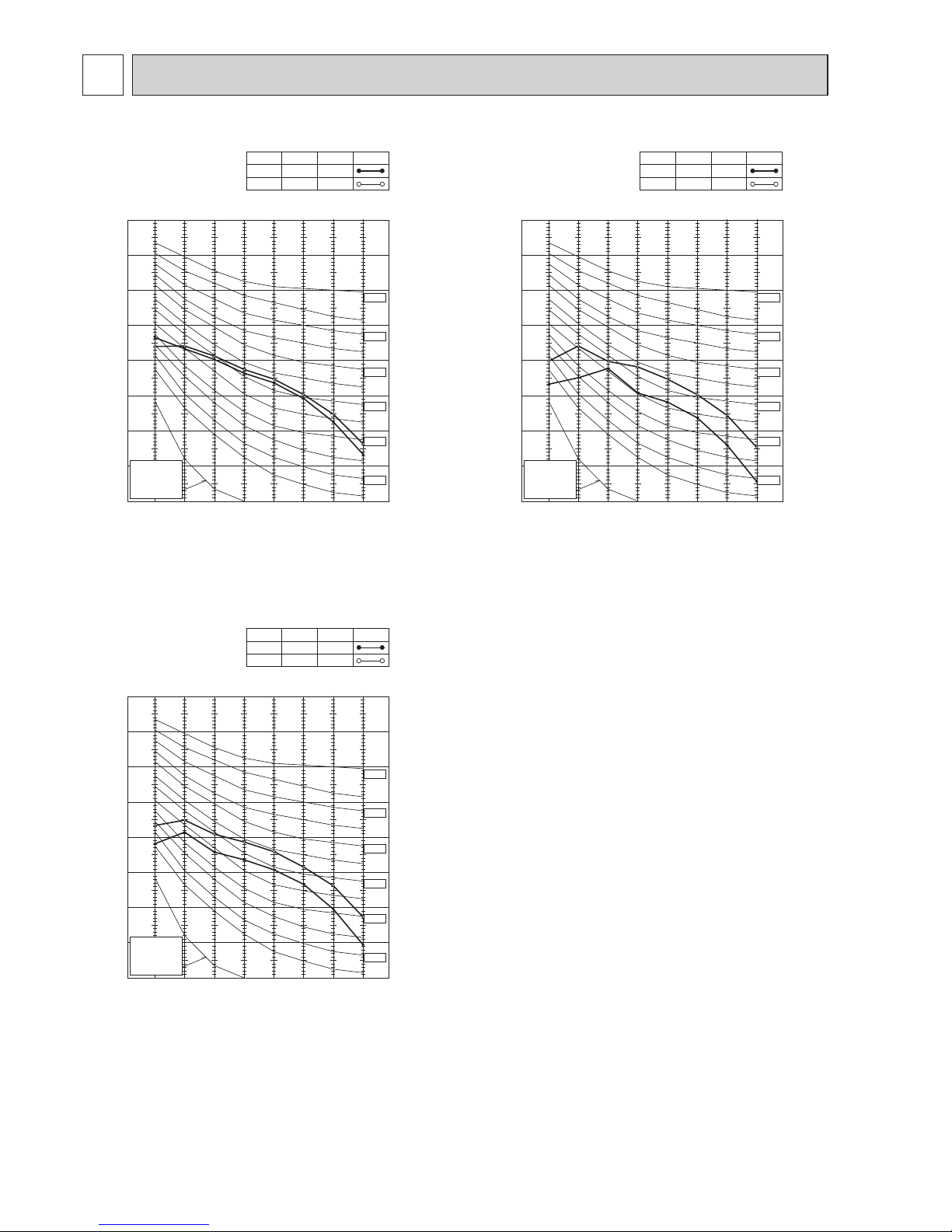
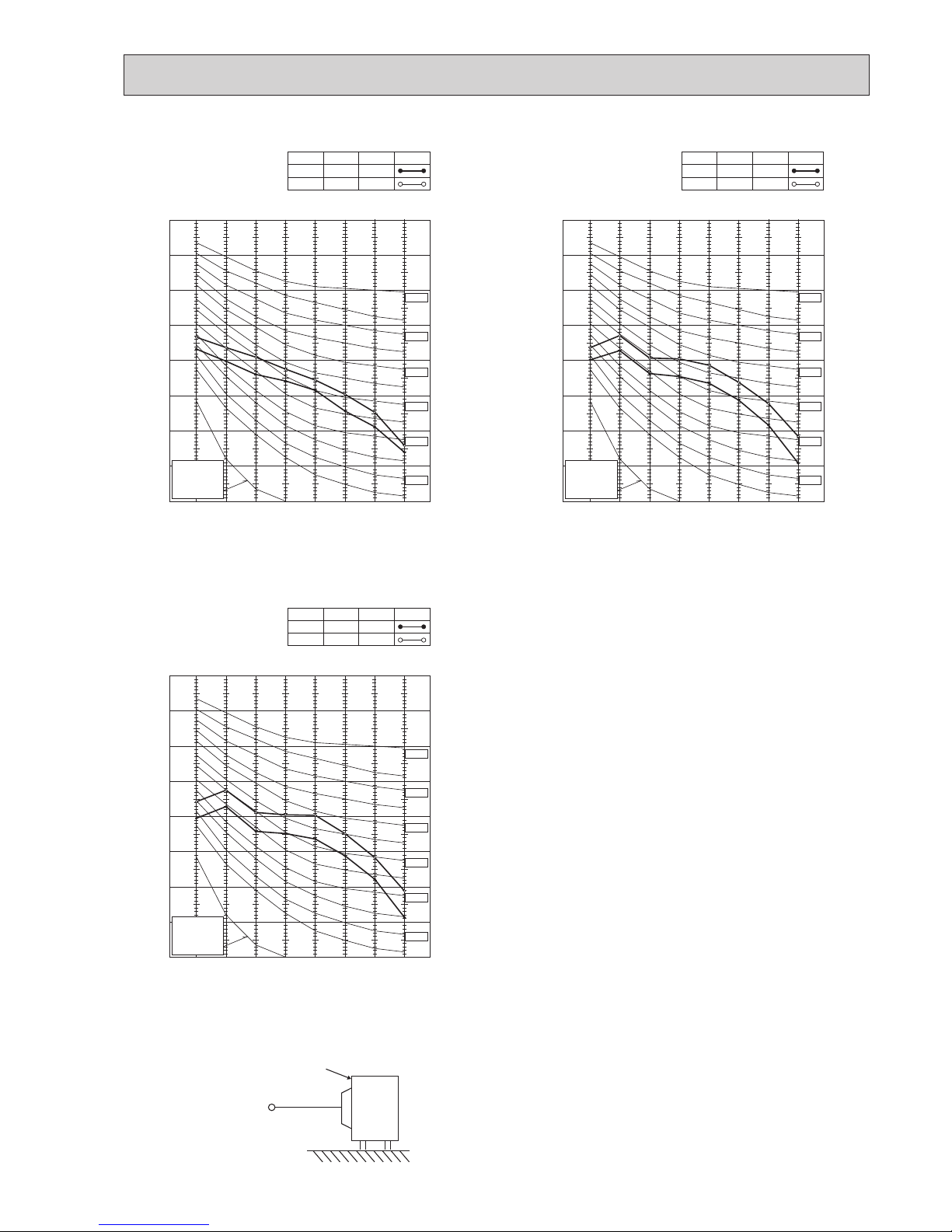
PERFORMANCE CURVES
9
The standard specifications apply only to the operation of the air conditioner under normal conditions.
Since operating conditions vary according to the areas where these units are installed, the following information has been pro-
vided to clarify the operating characteristics of the air conditioner under the conditions indicated by the performance curve.
(1) GUARANTEED VOLTAGE
198 - 264 V 50 Hz
(2) AIR FLOW
Air flow should be set at MAX.
(3) MAIN READINGS
(1) Indoor intake air wet-bulb temperature: °CWB
(2) Indoor outlet air wet-bulb temperature: °CWB
(3) Outdoor intake air dry-bulb temperature: °CDB
(4) Total input: W
(5) Indoor intake air dry-bulb temperature: °CDB
(6) Outdoor intake air wet-bulb temperature: °CWB
(7) Total input: W
Indoor air wet and dry bulb temperature difference on the left side of the following chart shows the difference between the
indoor intake air wet and dry bulb temperature and the indoor outlet air wet and dry bulb temperature for your reference at
service.
How to measure the indoor air wet and dry bulb temperature difference
1. Attach at least 2 sets of wet and dry bulb thermometers to the indoor air intake as shown in the figure, and at least 2 sets
of wet and dry bulb thermometers to the indoor air outlet. The thermometers must be attached to the position where air
speed is high.
2. Attach at least 2 sets of wet and dry bulb thermometers to the outdoor air intake.
Cover the thermometers to prevent direct rays of the sun.
3. Check that the air filter is cleaned.
4. Open windows and doors of room.
5. Press the EMERGENCY OPERATION switch once (twice) to start the EMERGENCY COOL (HEAT) MODE.
6. When system stabilizes after more than 15 minutes, measure temperature and take an average temperature.
7. 10 minutes later, measure temperature again and check that the temperature does not change.
INDOOR UNIT
OUTDOOR UNIT
}
}
Cooling
Heating
Wet and dry bulb
thermometers
BACK VIEW
Wet and dry bulb
thermometers
FRONT VIEW
MXZ-2F33VF MXZ-2F42VF MXZ-2F53VF MXZ-2F53VFH
MXZ-3F54VF MXZ-3F68VF MXZ-4F72VF
OBH790

36
9-1. CAPACITY AND THE INPUT CURVES
MXZ-2F33VF MXZ-2F42VF MXZ-2F53VF MXZ-2F53VFH
Cooling capacity
Capacity correction factors
1.4
0.9
1.0
1.1
1.2
1.3
-10 0 15 30 45
Outdoor intake air Dry - bulb temperature (ºC)
22
20
18
46-5 5 10 20 25 35 40
-10 0 15 30 45
Outdoor intake air Dry - bulb temperature (ºC)
46-5 5 10 20 25 35 40
Total input (Cooling)
Input correction factors
1.4
0.9
0.8
0.8
0.7
0.7
1.0
1.1
1.2
1.3
22
20
18
26
24
26
24
22 class
5.2
4.8
4.4
4.0
3.6
3.2
2.8
2.4
5.8
5.4
4.9
4.5
4.0
3.6
3.2
2.8
5.9
5.5
5.0
4.6
4.1
3.7
3.2
2.8
4.1
3.8
3.5
3.2
2.9
2.6
2.3
2.0
8.7
8.0
7.3
6.6
5.9
5.3
4.6
4.0
35 class
11.1
10.2
9.3
8.3
7.5
6.6
5.8
5.0
42 class
12.8
11.6
10.5
9.5
8.5
7.5
6.6
5.6
50 class
25 class
15 class
18 class
7.4
6.8
6.2
5.7
5.1
4.5
4.0
3.5
20 class
(MXZ-2F53)
(MXZ-2F42/53)
(
MXZ-2F53)
Indoor air Wet-bulb temperature
difference (°C)
Indoor intake air Wet-bulb temperature (°C)
Indoor intake air Wet-bulb temperature (°C)
-16 -8 -4 4 12 16
Capacity correction factors
Outdoor intake air Wet
-
bulb temperature (
ºC
)
15
20
26
0.6
0.7
0.8
0.9
1.0
1.1
1.2
1.3
0.5
0.4
Outdoor intake air Wet
-
Heating capacity
1.4
-12 0 8 18
-16 -8 -4 4 12 16
Outdoor intake air Wet
-
bulb temperature (
ºC
)
0.6
0.7
0.8
0.9
1.0
1.1
1.2
1.3
0.5
0.4
Outdoor intake air Wet
-
1.4
-12 0 8 18
26
20
15
Input correction factors
Total input (Heating)
26
20
15
Indoor intake air Dry-bulb temperature (°C)
Indoor intake air Dry-bulb temperature (°C)
22 class
25 class
35 class
42 class
(MXZ-2F53)
(MXZ-2F42/53)
50 class
(
MXZ-2F53)
15 class
18 class
20 class
Indoor air Dry-bulb temperature
difference (°C)
17.6
16.3
15.1
13.8
12.6
11.3
10.1
8.8
7.5
6.3
5.0
19.5
18.1
16.7
15.3
13.9
12.6
11.2
9.8
8.4
7.0
5.6
21.2
19.7
18.2
16.7
15.2
13.6
12.1
10.6
9.1
7.6
6.1
19.5
18.1
16.7
15.3
13.9
12.6
11.2
9.8
8.4
7.0
5.6
21.3
19.8
18.3
16.7
15.2
13.7
12.2
10.7
9.1
7.6
6.1
22.2
20.6
19.0
17.4
15.8
14.3
12.7
11.1
9.5
7.9
6.3
26.6
24.7
22.8
20.9
19.0
17.1
15.2
13.3
11.4
9.5
7.6
26.7
24.8
22.9
21.0
19.1
17.1
15.2
13.3
11.4
9.5
7.6
OBH790

37
0.9
1.0
1.1
1.2
1.3
1.4
0.8
-10 0 15
30
45 46
Capacity correction factors
Outdoor intake air Dry
- bulb temperature (
)
Cooling capacity
ºC
0.7
-5 5 10 20 25 35 40
-10 0 15
30
45 46
Outdoor intake air Dry
- bulb temperature (
)
ºC
-5 5 10 20 25 35 40
Input correction factors
Total input (Cooling)
0.9
1.0
1.1
1.2
1.3
1.4
0.8
0.7
0.6
0.5
0.4
18
16
19
22
20
24
26
18
16
19
22
20
24
26
Indoor air Wet-bulb temperature
difference (°C)
22 class
5.8
5.4
4.9
4.5
4.0
3.6
3.2
2.8
4.1
3.8
3.5
3.2
2.9
2.6
2.3
2.0
7.4
6.8
6.2
5.7
5.1
4.5
4.0
3.5
5.2
4.8
4.4
4.0
3.6
3.2
2.8
2.4
5.9
5.5
5.0
4.6
4.1
3.7
3.2
2.8
8.7
8.0
7.3
6.6
5.9
5.3
4.6
4.0
11.1
10.2
9.3
8.3
7.5
6.6
5.8
5.0
12.8
11.6
10.5
9.5
8.5
7.5
6.6
5.6
8.7
8.0
7.3
6.6
5.9
5.3
4.6
4.0
60 class
50 class
35 class
42 class
25 class
15 class
18 class
20 class
Indoor intake air Wet-bulb temperature (°C)
Indoor intake air Wet-bulb temperature (°C)
MXZ-3F54VF MXZ-3F68VF MXZ-4F72VF
0.6
0.7
0.8
0.9
1.0
1.1
1.2
1.3
-16 -8 -4 4 12 18
Capacity correction factors
Outdoor intake air Wet
-
bulb temperature (
ºC
)
Heating capacity
15
20
26
1.4
0.5
0.4
-12 0 8 16
-16 -8 -4 4 12 18-12 0 8 16
0.6
0.7
0.8
0.9
1.0
1.1
1.2
1.3
1.4
0.5
0.4
Input correction factors
Total input (Heating)
26
20
15
Outdoor intake air Wet
-
bulb temperature (
ºC
)
22 class
25 class
60 class
35 class
50 class
42 class
15 class
18 class
20 class
17.6
16.3
15.1
13.8
12.6
11.3
10.1
8.8
7.5
6.3
5.0
19.5
18.1
16.7
15.3
13.9
12.6
11.2
9.8
8.4
7.0
5.6
21.2
19.7
18.2
16.7
15.2
13.6
12.1
10.6
9.1
7.6
6.1
19.5
18.1
16.7
15.3
13.9
12.6
11.2
9.8
8.4
7.0
5.6
21.3
19.8
18.3
16.7
15.2
13.7
12.2
10.7
9.1
7.6
6.1
22.2
20.6
19.0
17.4
15.8
14.3
12.7
11.1
9.5
7.9
6.3
29.9
27.8
25.7
23.5
21.4
19.2
17.1
15.0
12.8
10.7
8.6
38.4
35.7
32.9
30.2
27.4
24.7
21.9
19.2
16.5
13.7
11.0
30.9
28.7
26.5
24.3
22.1
19.9
17.7
15.5
13.2
11.0
8.8
Indoor air Dry-bulb temperature
difference (°C)
Indoor intake air Dry-bulb temperature (°C)
Indoor intake air Dry-bulb temperature (°C)
OBH790

38
15-class unit
<COOL>Capacity
Frequency
Hz
<COOL>Total input
Frequency
Hz
<HEAT>Capacity
Frequency
Hz
0 50 100 150
0.5
1.0
1.5
2.0
050100150
0.5
1.0
1.5
2.0
2.5
3.0
<
HEAT>Total i
npu
t
Frequency
Hz
<HEAT>Capacity <HEAT>Total input
Frequency
Hz
Frequency
Hz
0 50 100 150
0.5
1.0
1.5
2.0
0 50 100 150
0.5
1.0
1.5
2.0
2.5
3.0
<COOL>Capacity
Frequency
Hz
050100150
0.5
1.0
1.5
2.0
2.5
050100150
0.5
1.0
1.5
2.0
2.5
3.0
<COOL>Total input
Frequency
Hz
<HEAT>Capacity <HEAT>Total input
Frequency
Hz
Frequency
Hz
0 50 100 150
0.5
1.0
1.5
2.0
0 50 100 150
0.5
1.0
1.5
2.0
2.5
3.0
<COOL>Capacity
Frequency
Hz
050100150
0.5
1.0
1.5
2.0
050100150
0.5
1.0
1.5
2.0
<COOL>Total input
Frequency
Hz
<HEAT>Capacity <HEAT>Total input
Frequency
Hz
Frequency
Hz
0 50 100 150
0.5
1.0
1.5
2.0
0 50 100 150
0.5
1.0
1.5
2.0
<COOL>Capacity
Frequency
Hz
050100150
0.5
1.0
1.5
2.0
050100150
0.5
1.0
1.5
2.0
2.5
<COOL>Total input
Frequency
Hz
<HEAT>Capacity
<HEAT>Total input
Frequency
Hz
Frequency
Hz
050100150
0.5
1.0
1.5
2.0
0 50 100 150
0.5
1.0
1.5
2.0
<COOL>Capacity
Frequency
Hz
050100150
0.5
1.0
1.5
2.0
050100150
0.5
1.0
1.5
2.0
2.5
<COOL>Total input
Frequency
Hz
0 50 100 150
0.5
1.0
1.5
2.0
050100150
0.5
1.0
1.5
2.0
2.5
9-2. CAPACITY AND INPUT CORRECTION BY INVERTER OUTPUT FREQUENCY (single operation)
MXZ-2F33VF
20-class unit
22-class unit
25-class unit
18-class unit
OBH790

39
<COOL>Capacity
Frequency
Hz
0 50 100 150
0.5
1.0
1.5
2.0
050100150
0.5
1.0
1.5
2.0
2.5
<COOL>Total input
Frequency
Hz
<COOL>Capacity
Frequency
Hz
0 50 100 150
0.5
1.0
1.5
2.0
050100150
0.5
1.0
1.5
2.0
2.5
3.0
<COOL>Total input
Frequency
Hz
<COOL>Capacity
Frequency
Hz
0 50 100 150
0.5
1.0
1.5
2.0
050100150
0.5
1.0
1.5
2.0
<COOL>Total input
Frequency
Hz
<COOL>Capacity
Frequency
Hz
0 50 100 150
0.5
1.0
1.5
2.0
050100150
0.5
1.0
1.5
2.0
<COOL>Total input
Frequency
Hz
<COOL>Capacity
Frequency
Hz
0 50 100 150
0.5
1.0
1.5
2.0
050100150
0.5
1.0
1.5
2.0
<COOL>Total input
Frequency
Hz
<HEAT>Capacity
Frequency
Hz
0 50 100 150
0.5
1.0
1.5
2.0
2.5
0 50 100 150
1.0
2.0
3.0
4.0
<HEAT>Total input
Frequency
Hz
<HEAT>Capacity
Frequency
Hz
0 50 100 150
0.5
1.0
1.5
2.0
0 50 100 150
0.5
1.0
1.5
2.0
<HEAT>Total input
Frequency
Hz
<HEAT>Capacity
Frequency
Hz
0 50 100 150
0.5
1.0
1.5
2.0
0 50 100 150
0.5
1.0
1.5
2.0
<HEAT>Total input
Frequency
Hz
<HEAT>Capacity
Frequency
Hz
0 50 100 150
0.5
1.0
1.5
2.0
0 50 100 150
0.5
1.0
1.5
2.0
2.5
<HEAT>Total input
Frequency
Hz
<HEAT>Capacity
Frequency
Hz
0 50 100 150
0.5
1.0
1.5
0 50 100 150
0.5
1.0
1.5
<HEAT>Total input
Frequency
Hz
15-class unit
20-class unit
22-class unit
25-class unit
MXZ-2F42VF
18-class unit
OBH790

40
<COOL>Capacity
Frequency
Hz
0 50 100 150
0.5
1.0
1.5
2.0
0 50 100 150
0.5
1.0
1.5
2.0
2.5
<COOL>Total input
Frequency
Hz
<COOL>Capacity
Frequency
Hz
0 50 100 150
0.5
1.0
1.5
2.0
0 50 100 150
0.5
1.0
1.5
2.0
2.5
3.0
<COOL>Total input
Frequency
Hz
<COOL>Capacity
Fre
q
uenc
y
Hz
0 50 100 150
0.5
1.0
1.5
2.0
0 50 100 150
0.5
1.0
1.5
2.0
<COOL>Total input
Fre
q
uenc
y
Hz
<COOL>Capacity
Frequency
Hz
0 50 100 150
0.5
1.0
1.5
2.0
0 50 100 150
0.5
1.0
1.5
2.0
<COOL>Total input
Frequency
Hz
<HEAT>Capacity
Frequency
Hz
0 50 100 150
0.5
1.0
1.5
2.0
2.5
0 50 100 150
1.0
2.0
3.0
4.0
<HEAT>Total input
Frequency
Hz
<HEAT>Capacity
Frequency
Hz
0 50 100 150
0.5
1.0
1.5
2.0
0 50 100 150
0.5
1.0
1.5
2.0
<HEAT>Total input
Frequency
Hz
<HEAT>Capacity
Fre
q
uenc
y
Hz
0 50 100 150
0.5
1.0
1.5
2.0
0 50 100 150
0.5
1.0
1.5
2.0
<HEAT>Total input
Fre
q
uenc
y
Hz
<HEAT>Capacity
Frequency
Hz
0 50 100 150
0.5
1.0
1.5
0 50 100 150
0.5
1.0
1.5
<HEAT>Total input
Frequency
Hz
MXZ-2F53VF MXZ-2F53VFH
15-class unit
18-class unit
20-class unit
22-class unit
35-class unit
MXZ-2F42VF
<COOL>Capacity
Frequency
Hz
0 50 100 150
0.5
1.0
1.5
2.0
0 50 100 150
0.5
1.0
1.5
2.0
2.5
<COOL>Total input
Frequency
Hz
<HEAT>Capacity
Frequency
Hz
050100150
0.5
1.0
1.5
2.0
0 50 100 150
0.5
1.0
1.5
2.0
<HEAT>Total input
Frequency
Hz
OBH790

41
<COOL>Capacity
Frequency
Hz
0 50 100 150
0.5
1.0
1.5
2.0
0 50 100 150
0.5
1.0
1.5
2.0
<COOL>Total input
Frequency
Hz
<HEAT>Capacity
Frequency
Hz
0 50 100 150
0.5
1.0
1.5
2.0
0 50 100 150
0.5
1.0
1.5
2.0
2.5
<HEAT>Total input
Frequency
Hz
<COOL>Capacity
Frequency
Hz
0 50 100 150
0.5
1.0
1.5
2.0
0 50 100 150
0.5
1.0
1.5
2.0
2.5
<COOL>Total input
Frequency
Hz
<HEAT>Capacity
Frequency
Hz
0 50 100 150
0.5
1.0
1.5
2.0
0 50 100 150
0.5
1.0
1.5
2.0
<HEAT>Total input
Frequency
Hz
<COOL>Capacity
Frequency
Hz
0 50 100 150
0.5
1.0
1.5
2.0
0 50 100 150
0.5
1.0
1.5
2.0
<COOL>Total input
Frequency
Hz
<HEAT>Capacity
Frequency
Hz
0 50 100 150
0.5
1.0
1.5
0 50 100 150
0.5
1.0
1.5
<HEAT>Total input
Frequency
Hz
<COOL>Capacity
Frequency
Hz
0 50 100 150
0.5
1.0
1.5
0 50 100 150
0.5
1.0
1.5
<COOL>Total input
Frequency
Hz
<HEAT>Capacity
Frequency
Hz
0 50 100 150
0.5
1.0
1.5
0 50 100 150
0.5
1.0
1.5
<HEAT>Total input
Frequency
Hz
25-class unit
35-class unit
42-class unit
50-class unit
MXZ-2F53VF MXZ-2F53VFH
OBH790

42
<COOL>Capacity
Frequency
Hz
0 50 100 150
0.5
1.0
1.5
2.0
2.5
0 50 100 150
0.5
1.0
1.5
2.0
2.5
<COOL>Total input
Frequency
Hz
<COOL>Capacity
Frequency
Hz
0 50 100 150
0.5
1.0
1.5
2.0
0 50 100 150
0.5
1.0
1.5
2.0
<COOL>Total input
Frequency
Hz
<COOL>Capacity
Frequency
Hz
0 50 100 150
0.5
1.0
1.5
2.0
0 50 100 150
0.5
1.0
1.5
2.0
<COOL>Total input
Frequency
Hz
<COOL>Capacity
Frequency
Hz
0 50 100 150
0.5
1.0
1.5
0 50 100 150
0.5
1.0
1.5
<COOL>Total input
Frequency
Hz
<HEAT>Capacity
Frequency
Hz
0 50 100 150
0.5
1.0
1.5
2.0
2.5
0 50 100 150
1.0
2.0
3.0
<HEAT>Total input
Frequency
Hz
<HEAT>Capacity
Frequency
Hz
0 50 100 150
0.5
1.0
1.5
0 50 100 150
0.5
1.0
1.5
<HEAT>Total input
Frequency
Hz
<HEAT>Capacity
Frequency
Hz
0 50 100 150
0.5
1.0
1.5
2.0
0 50 100 150
0.5
1.0
1.5
2.0
<HEAT>Total input
Frequency
Hz
<HEAT>Capacity
Frequency
Hz
0 50 100 150
0.5
1.0
1.5
0 50 100 150
0.5
1.0
1.5
<HEAT>Total input
Frequency
Hz
MXZ-3F54VF
15-class unit
22-class unit
18-class unit
20-class unit
OBH790

43
25-class unit
<COOL>Capacity
Frequency
Hz
0 50 100 150
0.5
1.0
1.5
2.0
0 50 100 150
0.5
1.0
1.5
2.0
<COOL>Total input
Frequency
Hz
<COOL>Capacity
Frequency
Hz
0 50 100 150
0.5
1.0
1.5
2.0
0 50 100 150
0.5
1.0
1.5
2.0
<COOL>Total input
Frequency
Hz
<COOL>Capacity
Frequency
Hz
0 50 100 150
0.5
1.0
1.5
0 50 100 150
0.5
1.0
1.5
<COOL>Total input
Frequency
Hz
<COOL>Capacity
Frequency
Hz
0 50 100 150
0.5
1.0
1.5
0 50 100 150
0.5
1.0
1.5
2.0
<COOL>Total input
Frequency
Hz
<HEAT>Capacity
Frequency
Hz
0 50 100 150
0.5
1.0
1.5
2.0
0 50 100 150
0.5
1.0
1.5
2.0
<HEAT>Total input
Frequency
Hz
<HEAT>Capacity
Frequency
Hz
0 50 100 150
0.5
1.0
1.5
2.0
0 50 100 150
0.5
1.0
1.5
2.0
<HEAT>Total input
Frequency
Hz
<HEAT>Capacity
Frequency
Hz
0 50 100 150
0.5
1.0
1.5
0 50 100 150
0.5
1.0
1.5
<HEAT>Total input
Frequency
Hz
<HEAT>Capacity
Frequency
Hz
0 50 100 150
0.5
1.0
1.5
0 50 100 150
0.5
1.0
1.5
<HEAT>Total input
Frequency
Hz
MXZ-3F54VF
35-class unit
42-class unit
50-class unit
OBH790

44
<COOL>Capacity
Frequency
Hz
0 50 100 150
0.5
1.0
1.5
2.0
2.5
0 50 100 150
0.5
1.0
1.5
2.0
2.5
<COOL>Total input
Frequency
Hz
<COOL>Capacity
Frequency
Hz
0 50 100 150
0.5
1.0
1.5
2.0
0 50 100 150
0.5
1.0
1.5
2.0
<COOL>Total input
Frequency
Hz
<COOL>Capacity
Frequency
Hz
0 50 100 150
0.5
1.0
1.5
2.0
0 50 100 150
0.5
1.0
1.5
2.0
<COOL>Total input
Frequency
Hz
<COOL>Capacity
Frequency
Hz
0 50 100 150
0.5
1.0
1.5
0 50 100 150
0.5
1.0
1.5
<COOL>Total input
Frequency
Hz
<HEAT>Capacity
Frequency
Hz
0 50 100 150
0.5
1.0
1.5
2.0
2.5
0 50 100 150
1.0
2.0
3.0
<HEAT>Total input
Frequency
Hz
<HEAT>Capacity
Frequency
Hz
0 50 100 150
0.5
1.0
1.5
0 50 100 150
0.5
1.0
1.5
<HEAT>Total input
Frequency
Hz
<HEAT>Capacity
Frequency
Hz
0 50 100 150
0.5
1.0
1.5
2.0
0 50 100 150
0.5
1.0
1.5
2.0
<HEAT>Total input
Frequency
Hz
<COOL>Capacity
Frequency
Hz
0 50 100 150
0.5
1.0
1.5
2.0
0 50 100 150
0.5
1.0
1.5
2.0
<COOL>Total input
Frequency
Hz
<HEAT>Capacity
Frequency
Hz
0 50 100 150
0.5
1.0
1.5
2.0
0 50 100 150
0.5
1.0
1.5
2.0
<HEAT>Total input
Frequency
Hz
<HEAT>Capacity
Frequency
Hz
0 50 100 150
0.5
1.0
1.5
0 50 100 150
0.5
1.0
1.5
<HEAT>Total input
Frequency
Hz
MXZ-3F68VF
15-class unit
22-class unit
25-class unit
20-class unit
18-class unit
OBH790

45
<COOL>Capacity
Frequency
Hz
0 50 100 150
0.5
1.0
1.5
2.0
0 50 100 150
0.5
1.0
1.5
2.0
<COOL>Total input
Frequency
Hz
<COOL>Capacity
Frequency
Hz
0 50 100 150
0.5
1.0
1.5
2.0
0 50 100 150
0.5
1.0
1.5
2.0
<COOL>Total input
Frequency
Hz
<COOL>Capacity
Frequency
Hz
0 50 100 150
0.5
1.0
1.5
0 50 100 150
0.5
1.0
1.5
2.0
<COOL>Total input
Frequency
Hz
<COOL>Capacity
Frequency
Hz
0 50 100 150
0.5
1.0
1.5
0 50 100 150
0.5
1.0
1.5
<COOL>Total input
Frequency
Hz
<HEAT>Capacity
Frequency
Hz
0 50 100 150
0.5
1.0
1.5
0 50 100 150
0.5
1.0
1.5
<HEAT>Total input
Frequency
Hz
<HEAT>Capacity
Frequency
Hz
0 50 100 150
0.5
1.0
1.5
0 50 100 150
0.5
1.0
1.5
2.0
<HEAT>Total input
Frequency
Hz
<HEAT>Capacity
Frequency
Hz
0 50 100 150
0.5
1.0
1.5
0 50 100 150
0.5
1.0
1.5
<HEAT>Total input
Frequency
Hz
<HEAT>Capacity
Frequency
Hz
0 50 100 150
0.5
1.0
1.5
0 50 100 150
0.5
1.0
1.5
<HEAT>Total input
Frequency
Hz
MXZ-3F68VF
35-class unit
42-class unit
50-class unit
60-class unit
OBH790

46
MXZ-4F72VF
<COOL>Capacity
Frequency
Hz
0 50 100 150
0.5
1.0
1.5
2.0
2.5
0 50 100 150
0.5
1.0
1.5
2.0
2.5
<COOL>Total input
Frequency
Hz
<COOL>Capacity
Frequency
Hz
0 50 100 150
0.5
1.0
1.5
2.0
0 50 100 150
0.5
1.0
1.5
2.0
<COOL>Total input
Frequency
Hz
<COOL>Capacity
Frequency
Hz
0 50 100 150
0.5
1.0
1.5
2.0
0 50 100 150
0.5
1.0
1.5
2.0
<COOL>Total input
Frequency
Hz
<COOL>Capacity
Frequency
Hz
0 50 100 150
0.5
1.0
1.5
0 50 100 150
0.5
1.0
1.5
<COOL>Total input
Frequency
Hz
<HEAT>Capacity
Frequency
Hz
0 50 100 150
0.5
1.0
1.5
2.0
2.5
0 50 100 150
1.0
2.0
3.0
<HEAT>Total input
Frequency
Hz
<HEAT>Capacity
Frequency
Hz
0 50 100 150
0.5
1.0
1.5
0 50 100 150
0.5
1.0
1.5
<HEAT>Total input
Frequency
Hz
<HEAT>Capacity
Frequency
Hz
0 50 100 150
0.5
1.0
1.5
2.0
0 50 100 150
0.5
1.0
1.5
2.0
<HEAT>Total input
Frequency
Hz
<COOL>Capacity
Frequency
Hz
0 50 100 150
0.5
1.0
1.5
2.0
0 50 100 150
0.5
1.0
1.5
2.0
<COOL>Total input
Frequency
Hz
<HEAT>Capacity
Frequency
Hz
0 50 100 150
0.5
1.0
1.5
2.0
0 50 100 150
0.5
1.0
1.5
2.0
<HEAT>Total input
Frequency
Hz
<HEAT>Capacity
Frequency
Hz
0 50 100 150
0.5
1.0
1.5
0 50 100 150
0.5
1.0
1.5
<HEAT>Total input
Frequency
Hz
15-class unit
22-class unit
25-class unit
20-class unit
18-class unit
OBH790

47
MXZ-4F72VF
<COOL>Capacity
Frequency
Hz
0 50 100 150
0.5
1.0
1.5
2.0
0 50 100 150
0.5
1.0
1.5
2.0
<COOL>Total input
Frequency
Hz
<COOL>Capacity
Frequency
Hz
0 50 100 150
0.5
1.0
1.5
2.0
0 50 100 150
0.5
1.0
1.5
2.0
<COOL>Total input
Frequency
Hz
<COOL>Capacity
Frequency
Hz
0 50 100 150
0.5
1.0
1.5
0 50 100 150
0.5
1.0
1.5
2.0
<COOL>Total input
Frequency
Hz
<COOL>Capacity
Frequency
Hz
0 50 100 150
0.5
1.0
1.5
0 50 100 150
0.5
1.0
1.5
<COOL>Total input
Frequency
Hz
<HEAT>Capacity
Frequency
Hz
0 50 100 150
0.5
1.0
1.5
0 50 100 150
0.5
1.0
1.5
<HEAT>Total input
Frequency
Hz
<HEAT>Capacity
Frequency
Hz
0 50 100 150
0.5
1.0
1.5
0 50 100 150
0.5
1.0
1.5
2.0
<HEAT>Total input
Frequency
Hz
<HEAT>Capacity
Frequency
Hz
0 50 100 150
0.5
1.0
1.5
0 50 100 150
0.5
1.0
1.5
<HEAT>Total input
Frequency
Hz
<HEAT>Capacity
Frequency
Hz
0 50 100 150
0.5
1.0
1.5
0 50 100 150
0.5
1.0
1.5
<HEAT>Total input
Frequency
Hz
35-class unit
42-class unit
50-class unit
60-class unit
OBH790

48
1. Press EMERGENCY OPERATION switch to start COOL or HEAT mode (COOL : Press once, HEAT : Press twice).
2. Test run operation starts and continues to operate for 30 minutes.
3. Compressor operates at rated frequency.
4. Indoor fan operates at High speed.
5. After 30 minutes, test run operation finishes and EMERGENCY OPERATION starts (Operation frequency of compressor
varies).
6. To cancel test run operation or EMERGENCY OPERATION, press EMERGENCY OPERATION switch or any button on
remote controller.
9-3. HOW TO OPERATE FIXED-FREQUENCY OPERATION <Test run operation>
Both indoor and outdoor units are under the
same temperature/humidity condition.
Operation : TEST RUN OPERATION (Refer to 9-3.)
Dry-bulb temperature (
)
Relative humidity (%)
20
50
25
60
30 70
9-4. OUTDOOR LOW PRESSURE AND OUTDOOR UNIT CURRENT CURVE
(single operation)
NOTE: The unit of pressure has been changed to MPa on the international system of units (SI unit system).
The conversion factor is : 1 (MPa [Gauge]) = 10.2 (kgf/cm2 [Gauge])
(1) COOL operation
MXZ-2F33VF
15-class unit
20-class unit
Outdoor low pressure
(MPa[Gauge])
Outdoor unit current (A)
Ambient temperature ( )
Ambient humidity (%)
Ambient temperature ( )
Ambient humidity (%)
50 60
70
(%)
50 60
70
(%)
(°C)
(°C)
48Hz
48Hz
12
11
10
9
8
7
6
15 20 25 30 35
0.6
0.7
0.8
0.9
1.0
1.1
1.2
15 20 25 30 35
1
2
3
4
5
6
Outdoor low pressure
(MPa[Gauge])
Outdoor unit current (A)
Ambient temperature ( )
Ambient humidity (%)
Ambient temperature ( )
Ambient humidity (%)
50 60
70
(%)
50 60
70
(%)
(°C)
(°C)
48Hz
48Hz
12
11
10
9
8
7
6
15 20 25 30 35
0.6
0.7
0.8
0.9
1.0
1.1
1.2
15 20 25 30 35
1
2
3
4
5
6
18-class unit
Outdoor low pressure
(MPa[Gauge])
Outdoor unit current (A)
Ambient temperature ( )
Ambient humidity (%)
Ambient temperature ( )
Ambient humidity (%)
50 60
70
(%)
(°C)
50 60
70
(%)
(°C)
48Hz
48Hz
13
12
11
10
9
8
7
15 20 25 30 35
0.7
0.8
0.9
1.0
1.1
1.2
1.3
15 20 25 30 35
0
1
2
3
4
5
22-class unit
Outdoor low pressure
(MPa[Gauge])
Outdoor unit current (A)
Ambient temperature ( )
Ambient humidity (%)
Ambient temperature ( )
Ambient humidity (%)
50 60
70
(%)
(°C)
50 60
70
(%)
(°C)
48Hz
48Hz
13
12
11
10
9
8
7
15 20 25 30 35
0.7
0.8
0.9
1.0
1.1
1.2
1.3
15 20 25 30 35
0
1
2
3
4
5
25-class unit
Outdoor low pressure
(MPa[Gauge])
Outdoor unit current (A)
Ambient temperature ( )
Ambient humidity (%)
Ambient temperature ( )
Ambient humidity (%)
50 60
70
(%)
(°C)
50 60
70
(%)
(°C)
48Hz
48Hz
13
12
11
10
9
8
7
15 20 25 30 35
0.7
0.8
0.9
1.0
1.1
1.2
1.3
15 20 25 30 35
0
1
2
3
4
5
OBH790

49
MXZ-2F42VF
15-class unit
20-class unit
Outdoor low pressure
(MPa[Gauge])
Outdoor unit current (A)
Ambient temperature ( )
Ambient humidity (%)
Ambient temperature ( )
Ambient humidity (%)
50 60
70
(%)
(°C)
50 60
70
(%)
(°C)
30Hz
30Hz
12
11
10
9
8
7
6
15 20 25 30 35
0.6
0.7
0.8
0.9
1.0
1.1
1.2
15 20 25 30 35
1
2
3
4
5
6
Outdoor low pressure
(MPa[Gauge])
Outdoor unit current (A)
Ambient temperature ( )
Ambient humidity (%)
Ambient temperature ( )
Ambient humidity (%)
50 60
70
(%)
(°C)
50 60
70
(%)
(°C)
30Hz
30Hz
12
11
10
9
8
7
6
15 20 25 30 35
0.6
0.7
0.8
0.9
1.0
1.1
1.2
15 20 25 30 35
1
2
3
4
5
6
22-class unit
25-class unit 35-class unit
Outdoor low pressure
(MPa[Gauge])
Outdoor unit current (A)
Ambient temperature ( )
Ambient humidity (%)
Ambient temperature ( )
Ambient humidit
y (%)
50 60
70
(%)
50 60
70
(%)
(°C)
(°C)
30Hz
30Hz
13
12
11
10
9
8
7
15 20 25 30 35
0.7
0.8
0.9
1.0
1.1
1.2
1.3
15 20 25 30 35
1
2
3
4
5
6
Outdoor low pressure
(MPa[Gauge])
Outdoor unit current (A)
Ambient temperature ( )
Ambient humidity (%)
Ambient temperature ( )
Ambient humidity (%)
50 60
70
(%)
(°C)
50 60
70
(%)
(°C)
30Hz
30Hz
13
12
11
10
9
8
7
15 20 25 30 35
0.7
0.8
0.9
1.0
1.1
1.2
1.3
15 20 25 30 35
1
2
3
4
5
6
Outdoor low pressure
(MPa[Gauge])
Outdoor unit current (A)
Ambient temperature ( )
Ambient humidity (%)
Ambient temperature ( )
Ambient humidity (%)
50 60
70
(%)
(°C)
50 60
70
(%)
(°C)
30Hz
30Hz
13
12
11
10
9
8
7
15 20 25 30 35
0.7
0.8
0.9
1.0
1.1
1.2
1.3
15 20 25 30 35
1
2
3
4
5
6
18-class unit
Outdoor low pressure
(MPa[Gauge])
Outdoor unit current (A)
Ambient temperature ( )
Ambient humidity (%)
Ambient temperature ( )
Ambient humidit
y (%)
50 60
70
(%)
50 60
70
(%)
(°C)
(°C)
30Hz
30Hz
13
12
11
10
9
8
7
15 20 25 30 35
0.7
0.8
0.9
1.0
1.1
1.2
1.3
15 20 25 30 35
1
2
3
4
5
6
OBH790

50
MXZ-2F53VF MXZ-2F53VFH
15-class unit
20-class unit
Outdoor low pressure
(MPa[Gauge])
Outdoor unit current (A)
Ambient temperature ( )
Ambient humidity (%)
Ambient temperature ( )
Ambient humidity (%)
50 60
70
(%)
(°C)
50 60
70
(%)
(°C)
30Hz
30Hz
12
11
10
9
8
7
6
15 20 25 30 35
0.6
0.7
0.8
0.9
1.0
1.1
1.2
15 20 25 30 35
1
2
3
4
5
6
Outdoor low pressure
(MPa[Gauge])
Outdoor unit current (A)
Ambient temperature ( )
Ambient humidity (%)
Ambient temperature ( )
Ambient humidity (%)
50 60
70
(%)
(°C)
50 60
70
(%)
(°C)
30Hz
30Hz
12
11
10
9
8
7
6
15 20 25 30 35
0.6
0.7
0.8
0.9
1.0
1.1
1.2
15 20 25 30 35
1
2
3
4
5
6
22-class unit
25-class unit 35-class unit
Outdoor low pressure
(MPa[Gauge])
Outdoor unit current (A)
Ambient temperature ( )
Ambient humidity (%)
Ambient temperature ( )
Ambient humidit
y (%)
50 60
70
(%)
50 60
70
(%)
(°C)
(°C)
30Hz
30Hz
13
12
11
10
9
8
7
15 20 25 30 35
0.7
0.8
0.9
1.0
1.1
1.2
1.3
15 20 25 30 35
1
2
3
4
5
6
Outdoor low pressure
(MPa[Gauge])
Outdoor unit current (A)
Ambient temperature ( )
Ambient humidity (%)
Ambient temperature ( )
Ambient humidity (%)
50 60
70
(%)
(°C)
50 60
70
(%)
(°C)
30Hz
30Hz
13
12
11
10
9
8
7
15 20 25 30 35
0.7
0.8
0.9
1.0
1.1
1.2
1.3
15 20 25 30 35
1
2
3
4
5
6
Outdoor low pressure
(MPa[Gauge])
Outdoor unit current (A)
Ambient temperature ( )
Ambient humidity (%)
Ambient temperature ( )
Ambient humidity (%)
50 60
70
(%)
(°C)
50 60
70
(%)
(°C)
30Hz
30Hz
13
12
11
10
9
8
7
15 20 25 30 35
0.7
0.8
0.9
1.0
1.1
1.2
1.3
15 20 25 30 35
1
2
3
4
5
6
18-class unit
Outdoor low pressure
(MPa[Gauge])
Outdoor unit current (A)
Ambient temperature ( )
Ambient humidity (%)
Ambient temperature ( )
Ambient humidit
y (%)
50 60
70
(%)
50 60
70
(%)
(°C)
(°C)
30Hz
30Hz
13
12
11
10
9
8
7
15 20 25 30 35
0.7
0.8
0.9
1.0
1.1
1.2
1.3
15 20 25 30 35
1
2
3
4
5
6
Outdoor low pressure
(MPa[Gauge])
Outdoor unit current (A)
Ambient temperature ( )
Ambient humidity (%)
Ambient temperature ( )
Ambient humidity (%)
50 60
70
(%)
(°C)
50 60
70
(%)
(°C)
30Hz
30Hz
13
12
11
10
9
8
7
15 20 25 30 35
0.7
0.8
0.9
1.0
1.1
1.2
1.3
15 20 25 30 35
1
2
3
4
5
6
Outdoor low pressure
(MPa[Gauge])
Outdoor unit current (A)
Ambient temperature ( )
Ambient humidity (%)
Ambient temperature ( )
Ambient humidity (%)
50 60
70
(%)
(°C)
50 60
70
(%)
(°C)
30Hz
30Hz
13
12
11
10
9
8
7
15 20 25 30 35
0.7
0.8
0.9
1.0
1.1
1.2
1.3
15 20 25 30 35
1
2
3
4
5
6
42-class unit 50-class unit
OBH790

51
15-class unit
MXZ-3F54VF
Outdoor low pressure
(MPa[Gauge])
Outdoor unit current (A)
Ambient temperature ( )
Ambient humidity (%)
Ambient temperature ( )
Ambient humidity (%)
50 60
70
(%)
(°C)
50 60
70
(%)
(°C)
40Hz
40Hz
12
11
10
9
8
7
6
15 20 25 30 35
0.6
0.7
0.8
0.9
1.0
1.1
1.2
15 20 25 30 35
1
2
3
4
5
6
18-class unit
Outdoor low pressure
(MPa[Gauge])
Outdoor unit current (A)
Ambient temperature ( )
Ambient humidity (%)
Ambient temperature ( )
Ambient humidity (%)
50 60
70
(%)
(°C)
50 60
70
(%)
(°C)
40Hz
40Hz
13
12
11
10
9
8
7
15 20 25 30 35
0.7
0.8
0.9
1.0
1.1
1.2
1.3
15 20 25 30 35
1
2
3
4
5
6
22-class unit 20-class unit
Outdoor low pressure
(MPa[Gauge])
Outdoor unit current (A)
Ambient temperature ( )
Ambient humidity (%)
Ambient temperature ( )
Ambient humidity (%)
50 60
70
(%)
(°C)
50 60
70
(%)
(°C)
40Hz
40Hz
13
12
11
10
9
8
7
15 20 25 30 35
0.7
0.8
0.9
1.0
1.1
1.2
1.3
15 20 25 30 35
1
2
3
4
5
6
Outdoor low pressure
(MPa[Gauge])
Outdoor unit current (A)
Ambient temperature ( )
Ambient humidity (%)
Ambient temperature ( )
Ambient humidity (%)
50 60
70
(%)
(°C)
50 60
70
(%)
(°C)
40Hz
40Hz
12
11
10
9
8
7
6
15 20 25 30 35
0.6
0.7
0.8
0.9
1.0
1.1
1.2
15 20 25 30 35
1
2
3
4
5
6
25-class unit 35-class unit
Outdoor low pressure
(MPa[Gauge])
Outdoor unit current (A)
Ambient temperature ( )
Ambient humidity (%)
Ambient temperature ( )
Ambient humidity (%)
50 60
70
(%)
(°C)
50 60
70
(%)
(°C)
40Hz
40Hz
14
13
12
11
10
9
8
15 20 25 30 35
0.8
0.9
1.0
1.1
1.2
1.3
1.4
15 20 25 30 35
1
2
3
4
5
6
Outdoor low pressure
(MPa[Gauge])
Outdoor unit current (A)
Ambient temperature ( )
Ambient humidity (%)
Ambient temperature ( )
Ambient humidity (%)
50 60
70
(%)
(°C)
50 60
70
(%)
(°C)
40Hz
40Hz
14
13
12
11
10
9
8
15 20 25 30 35
0.8
0.9
1.0
1.1
1.2
1.3
1.4
15 20 25 30 35
1
2
3
4
5
6
42-class unit 50-class unit
Outdoor low pressure
(MPa[Gauge])
Outdoor unit current (A)
Ambient temperature ( )
Ambient humidity (%)
Ambient temperature ( )
Ambient humidity (%)
50 60
70
(%)
(°C)
50 60
70
(%)
(°C)
40Hz
40Hz
14
13
12
11
10
9
8
15 20 25 30 35
0.8
0.9
1.0
1.1
1.2
1.3
1.4
15 20 25 30 35
1
2
3
4
5
6
Outdoor low pressure
(MPa[Gauge])
Outdoor unit current (A)
Ambient temperature ( )
Ambient humidity (%)
Ambient temperature ( )
Ambient humidity (%)
50 60
70
(%)
(°C)
50 60
70
(%)
(°C)
40Hz
40Hz
14
13
12
11
10
9
8
15 20 25 30 35
0.8
0.9
1.0
1.1
1.2
1.3
1.4
15 20 25 30 35
1
2
3
4
5
6
MXZ-3F54VF
OBH790

52
15-class unit
MXZ-3F68VF MXZ-4F72VF
Outdoor low pressure
(MPa[Gauge])
Outdoor unit current (A)
Ambient temperature ( )
Ambient humidity (%)
Ambient temperature ( )
Ambient humidity (%)
50 60
70
(%)
(°C)
50 60
70
(%)
(°C)
30Hz
30Hz
12
11
10
9
8
7
6
15 20 25 30 35
0.6
0.7
0.8
0.9
1.0
1.1
1.2
15 20 25 30 35
1
2
3
4
5
6
18-class unit
Outdoor low pressure
(MPa[Gauge])
Outdoor unit current (A)
Ambient temperature ( )
Ambient humidity (%)
Ambient temperature ( )
Ambient humidity (%)
50 60
70
(%)
(°C)
50 60
70
(%)
(°C)
30Hz
30Hz
13
12
11
10
9
8
7
15 20 25 30 35
0.7
0.8
0.9
1.0
1.1
1.2
1.3
15 20 25 30 35
1
2
3
4
5
6
20-class unit
Outdoor low pressure
(MPa[Gauge])
Outdoor unit current (A)
Ambient temperature ( )
Ambient humidity (%)
Ambient temperature ( )
Ambient humidity (%)
50 60
70
(%)
(°C)
50 60
70
(%)
(°C)
30Hz
30Hz
12
11
10
9
8
7
6
15 20 25 30 35
0.6
0.7
0.8
0.9
1.0
1.1
1.2
15 20 25 30 35
1
2
3
4
5
6
22-class unit
Outdoor low pressure
(MPa[Gauge])
Outdoor unit current (A)
Ambient temperature ( )
Ambient humidity (%)
Ambient temperature ( )
Ambient humidity (%)
50 60
70
(%)
(°C)
50 60
70
(%)
(°C)
30Hz
30Hz
13
12
11
10
9
8
7
15 20 25 30 35
0.7
0.8
0.9
1.0
1.1
1.2
1.3
15 20 25 30 35
1
2
3
4
5
6
42-class unit
Outdoor low pressure
(MPa[Gauge])
Outdoor unit current (A)
Ambient temperature ( )
Ambient humidity (%)
Ambient temperature ( )
Ambient humidity (%)
50 60
70
(%)
(°C)
50 60
70
(%)
(°C)
30Hz
30Hz
14
13
12
11
10
9
8
15 20 25 30 35
0.8
0.9
1.0
1.1
1.2
1.3
1.4
15 20 25 30 35
1
2
3
4
5
6
50-class unit
Outdoor low pressure
(MPa[Gauge])
Outdoor unit current (A)
Ambient temperature ( )
Ambient humidity (%)
Ambient temperature ( )
Ambient humidity (%)
50 60
70
(%)
(°C)
50 60
70
(%)
(°C)
30Hz
30Hz
14
13
12
11
10
9
8
15 20 25 30 35
0.8
0.9
1.0
1.1
1.2
1.3
1.4
15 20 25 30 35
1
2
3
4
5
6
25-class unit
Outdoor low pressure
(MPa[Gauge])
Outdoor unit current (A)
Ambient temperature ( )
Ambient humidity (%)
Ambient temperature ( )
Ambient humidity (%)
50 60
70
(%)
(°C)
50 60
70
(%)
(°C)
30Hz
30Hz
14
13
12
11
10
9
8
15 20 25 30 35
0.8
0.9
1.0
1.1
1.2
1.3
1.4
15 20 25 30 35
1
2
3
4
5
6
35-class unit
Outdoor low pressure
(MPa[Gauge])
Outdoor unit current (A)
Ambient temperature ( )
Ambient humidity (%)
Ambient temperature ( )
Ambient humidity (%)
50 60
70
(%)
(°C)
50 60
70
(%)
(°C)
30Hz
30Hz
14
13
12
11
10
9
8
15 20 25 30 35
0.8
0.9
1.0
1.1
1.2
1.3
1.4
15 20 25 30 35
1
2
3
4
5
6
OBH790

53
MXZ-3F68VF MXZ-4F72VF
60-class unit
Outdoor low pressure
(MPa[Gauge])
Outdoor unit current (A)
Ambient temperature ( )
Ambient humidity (%)
Ambient temperature ( )
Ambient humidity (%)
50 60
70
(%)
50 60
70
(%)
30Hz
30Hz
14
13
12
11
10
9
8
15 20 25 30
35
0.8
0.9
1.0
1.1
1.2
1.3
1.4
15 20 25 30 35
1
2
3
4
5
6
Condition :
Operation : TEST RUN OPERATION (Refer to 9-3.)
(2) HEAT operation
Dry bulb temperature (°C)
Indoor
20.0
14.5
2
1
Outdoor
7
6
151220.0
14.5
Wet bulb temperature (°C)
MXZ-2F33VF
15-class unit
25-class unit
20-class unit
22-class unit
0 5 10 15 20 25
2
3
4
5
6
7
Ambient temperature ( )
58Hz
Outdoor unit current (A)
0 5 10 15 20 25
2
3
4
5
6
7
Ambient temperature ( )
58Hz
Outdoor unit current (A)
0 5 10 15 20 25
2
3
4
5
6
7
Ambient temperature ( )
58Hz
Outdoor unit current (A)
0 5 10 15 20 25
2
3
4
5
6
7
Ambient temperature ( )
58Hz
Outdoor unit current (A)
18-class unit
0 5 10 15 20 25
2
3
4
5
6
7
Ambient temperature ( )
58Hz
Outdoor unit current (A)
OBH790

54
MXZ-2F42VF
15-class unit
0 5 10 15 20 25
2
3
4
5
6
7
Ambient temperature ( )
34Hz
Outdoor unit current (A)
20-class unit
0 5 10 15 20 25
2
3
4
5
6
7
Ambient temperature ( )
34Hz
Outdoor unit current (A)
22-class unit
0 5 10 15 20 25
2
3
4
5
6
7
Ambient temperature ( )
34Hz
Outdoor unit current (A)
25-class unit
0 5 10 15 20 25
2
3
4
5
6
7
Ambient temperature ( )
34Hz
Outdoor unit current (A)
35-class unit
0 5 10 15 20 25
2
3
4
5
6
7
Ambient temperature ( )
34Hz
Outdoor unit current (A)
18-class unit
0 5 10 15 20 25
2
3
4
5
6
7
Ambient temperature ( )
34Hz
Outdoor unit current (A)
25-class unit
0 5 10 15 20 25
2
3
4
5
6
7
Ambient temperature ( )
34Hz
Outdoor unit current (A)
35-class unit 42-class unit
0 5 10 15 20 25
2
3
4
5
6
7
Ambient temperature ( )
34Hz
Outdoor unit current (A)
0 5 10 15 20 25
2
3
4
5
6
7
Ambient temperature ( )
34Hz
Outdoor unit current (A)
0 5 10 15 20 25
2
3
4
5
6
7
Ambient temperature ( )
34Hz
Outdoor unit current (A)
50-class unit
15-class unit 20-class unit 22-class unit
0 5 10 15 20 25
2
3
4
5
6
7
Ambient temperature ( )
34Hz
Outdoor unit current (A)
0 5 10 15 20 25
2
3
4
5
6
7
Ambient temperature ( )
34Hz
Outdoor unit current (A)
0 5 10 15 20 25
2
3
4
5
6
7
Ambient temperature ( )
34Hz
Outdoor unit current (A)
18-class unit
0 5 10 15 20 25
2
3
4
5
6
7
Ambient temperature ( )
34Hz
Outdoor unit current (A)
MXZ-2F53VF MXZ-2F53VFH
OBH790

55
22-class unit
50-class unit 25-class unit
MXZ-3F54VF
15-class unit
20-class unit
42-class unit
0 5 10 15 20 25
2
3
4
5
6
7
Ambient temperature ( )
48Hz
Outdoor unit current (A)
0 5 10 15 20 25
2
3
4
5
6
7
Ambient temperature ( )
48Hz
Outdoor unit current (A)
0 5 10 15 20 25
2
3
4
5
6
7
Ambient temperature ( )
48Hz
Outdoor unit current (A)
0 5 10 15 20 25
2
3
4
5
6
7
Ambient temperature ( )
48Hz
Outdoor unit current (A)
0 5 10 15 20 25
2
3
4
5
6
7
Ambient temperature ( )
48Hz
Outdoor unit current (A)
0 5 10 15 20 25
2
3
4
5
6
7
Ambient temperature ( )
48Hz
Outdoor unit current (A)
0 5 10 15 20 25
2
3
4
5
6
7
Ambient temperature ( )
48Hz
Outdoor unit current (A)
18-class unit
35-class unit
0 5 10 15 20 25
2
3
4
5
6
7
Ambient temperature ( )
48Hz
Outdoor unit current (A)
22-class unit
25-class unit 35-class unit
MXZ-3F68VF MXZ-4F72VF
42-class unit
50-class unit
15-class unit
20-class unit
0 5 10 15 20 25
2
3
4
5
6
7
Ambient temperature ( )
36Hz
Outdoor unit current (A)
0 5 10 15 20 25
2
3
4
5
6
7
Ambient temperature ( )
36Hz
Outdoor unit current (A)
0 5 10 15 20 25
2
3
4
5
6
7
Ambient temperature ( )
36Hz
Outdoor unit current (A)
0 5 10 15 20 25
2
3
4
5
6
7
Ambient temperature ( )
36Hz
Outdoor unit current (A)
0 5 10 15 20 25
2
3
4
5
6
7
Ambient temperature ( )
36Hz
Outdoor unit current (A)
0 5 10 15 20 25
2
3
4
5
6
7
Ambient temperature ( )
36Hz
Outdoor unit current (A)
0 5 10 15 20 25
2
3
4
5
6
7
Ambient temperature ( )
36Hz
Outdoor unit current (A)
18-class unit
0 5 10 15 20 25
2
3
4
5
6
7
Ambient temperature ( )
36Hz
Outdoor unit current (A)
60-class unit
0 5 10 15 20 25
2
3
4
5
6
7
Ambient temperature ( )
36Hz
Outdoor unit current (A)
OBH790

56
ACTUATOR CONTROL
10
Relation between main sensor and actuator
Sensor Purpose
Actuator
Compressor LEV
Outdoor
fan motor
4-way
valve
Discharge temperature
thermistor
Protection
Indoor coil
temperature thermistor
Cooling: Coil frost prevention
Heating: High pressure protection
Defrost thermistor Heating: Defrosting
Fin temperature thermistor Protection
Ambient temperature
thermistor
Control/Protection
Heating: Defrosting (Heater)
Outdoor heat exchanger
temperature thermistor
Cooling: Control/Protection
Capacity code Control
MXZ-3F54VF MXZ-3F68VF MXZ-4F72VF
Relation between main sensor and actuator
Sensor Purpose
Actuator
Compressor LEV
Outdoor
fan motor
R.V. coil
Defrost
heater
1
Discharge temperature thermistor Protection
Indoor coil temperature thermistor
Cooling: Coil frost prevention
Heating: High pressure protection
Defrost thermistor Heating: Defrosting
Fin temperature thermistor Protection
Ambient temperature thermistor
Control/Protection
Heating: Defrosting (Heater)
Outdoor heat exchanger
temperature thermistor
Cooling: Control/Protection
Capacity code Control
1 MXZ-2F53VFH only.
MXZ-2F33VF MXZ-2F42VF MXZ-2F53VF MXZ-2F53VFH
OBH790

57
SERVICE FUNCTIONS
11
MXZ-2F33VF MXZ-2F42VF MXZ-2F53VF MXZ-2F53VFH
MXZ-3F54VF MXZ-3F68VF MXZ-4F72VF
<MXZ-3F54VF MXZ-3F68VF MXZ-4F72VF>
11-1. THE POSITION OF SWITCH
<MXZ-2F33VF/2F42VF/2F53VF/2F53VFH>
With this function, once the operation mode is locked to either COOL/DRY mode or HEAT mode, the air conditioner
operates in that mode only.
Changing the setting is required to activate this function. Explain about this function to your customers and ask them
whether they want to use it.
[How to lock the operation mode]
(1) Turn OFF the power supply and make sure that the LED goes off.
(2) Set SW1 as shown in the figure below.
(3) Turn ON the power supply.
11-2. LOCKING THE OPERATION MODE OF THE AIR CONDITIONER (COOL, DRY, HEAT)
SW1 on the outdoor display P.C. board
<MXZ-2F33VF/2F42VF/2F53VF/2F53VFH> <MXZ-3F53VF/3F68VF/4F72VF>
SW1 on the outdoor control P.C. board
ON
SW1
ON
SW1
Cool/Dry Heat
ON
5
6
SW1
ON
5
6
SW1
Cool/Dry Heat
Outdoor display P.C. board
SW1 SW2
ON
123456
ON
ON
1 2 3 4 5 6
SW1
ON
1 2 3 4 5 6
SW2
CN750
CN751
SW871
Outdoor control
P.C. board
OBH790

58
<MXZ-2F33VF/2F42VF/2F53VF/2F53VFH> <MXZ-3F53VF/3F68VF/4F72VF>
SW1 on the outdoor control P.C. board
11-4.
LOWERING THE OPERATING NOISE OF THE OUTDOOR UNIT
With this function, the operating noise of the outdoor unit can be lowered by reducing the operation load, for example,
during nighttime in COOL mode.
However, note that the cooling and heating capacity may lower if this function is activated.
Changing the setting is required to activate this function. Explain about this function to your customers and ask them
whether they want to use it.
[How to lower the operating noise]
(1) Turn OFF the power supply and make sure that the LED goes off.
(2) Set the "3" switch of SW1 to ON to enable this function. (MXZ-2F33VF/2F42VF/2F53VF/2F53VFH)
Set the "5" switch of the SW1 to ON the enable this function. (MXZ-3F53VF/3F68VF/4F72VF)
(3) Turn ON the power supply.
SW1 on the outdoor display P.C. board
ON
SW1
ON
5
6
SW1
11-3. HOW TO SET LOW STANDBY POWER MODE
MXZ-3F54VF MXZ-3F68VF MXZ-4F72VF
• Before turning on the power supply, settings for dip switch (SW1) and jumper connector (SC751) are necessary
on the outdoor controller board.
• When connecting the ducted type indoor unit, deactivate low standby power mode.
To activate low standby power mode:
Connect SC751 to CN750.
Set the 2 of SW1 to ON.
To deactivate low standby power mode:
Connect SC751 to CN751.
Set the 2 of SW1 to OFF.
NOTE:
• Units come with low standby power mode activated as factory setting.
• When connecting the ducted type indoor unit, outdoor unit will not work with low standby power mode activated.
• In the event that SC751 is missing, outdoor unit will not work.
SC751 SW1 MODE
CN750
Activated
CN751
Deactivated
OBH790

59
11-5. AUTOMATIC LINE CORRECTING
<MXZ-2F33VF/2F42VF/2F53VF/2F53VFH>
This outdoor unit has an automatic line correcting function which automatically detects and corrects improper wiring or piping.
<MXZ-2F33VF/2F42VF/2F53VF/2F53VFH>
Improper wiring or piping can be automatically detected when one indoor unit is operated in COOL mode for 30 minutes.
When improper wiring or piping is detected, wiring lines are corrected (A to B/ B to A) with the software.
NOTE: This function may not work due to the condition or environment of the unit, such as the following:
- gas leak, closed stop valve
- unit failure such as defective LEV
- indoor/outdoor temperature
NOTE: This function does not work when the "2" of SW2 on the outdoor display P.C. board is turned OFF.
SW2
<Correct>
Indoor/outdoor
connecting wire
Terminal
block
Refrigerant pipe
Indoor unit B
Liquid/
Gas pipe
Indoor unit A
Outdoor unit
<Incorrect wiring>
Terminal
block
Indoor unit B
Liquid/
Gas pipe
Indoor unit A
Outdoor unit
<Incorrect piping>
Terminal
block
Indoor unit B
Liquid/
Gas pipe
Indoor unit A
Outdoor unit
B
A
B
A
B
A
B
A
B
A
B
A
MXZ-2F33VF/2F42VF/2F53VF/2F53VFH
SW2 on the outdoor display P.C. board
The record of automatic line correcting can be checked in the following way:
(1) Turn OFF the power supply and make sure that the LED goes off.
(2) Turn ON the "3" of SW2 on the outdoor display P.C. board.
(3) Turn ON the power supply.
(4) Check the correction state with the LED lamps on the outdoor display P.C. board.
(5) Turn OFF the power supply and make sure that the LED goes off.
(6) Turn OFF the "3" of SW2 on the outdoor display P.C. board.
(7) Turn ON the power supply.
Number of blinks
Wiring line
LED1 (Red) LED2 (Yellow)
Once Once Not corrected
3 times 3 times Corrected
SW2
MXZ-2F33VF/2F42VF/2F53VF/2F53VFH
SW2 on the outdoor display P.C. board
OBH790

60
<MXZ-3F54VF/3F68VF/4F72VF>
Outdoor unit has an auto line correcting function which automatically detects and corrects improper wiring or piping.
Improper wiring or piping can be automatically detected by pressing the piping/wiring correction switch (SW871).
When improper wiring or piping is detected, wiring lines are corrected.
This will be completed in about 10 to 15 minutes.
[How to activate this function]
&KHFNWKDWRXWVLGHWHPSHUDWXUHLVDERYHÛ&
7KLVIXQFWLRQGRHVQRWZRUNZKHQWKHRXWVLGHWHPSHUDWXUHLVÛ&RUEHORZ
2. Check that the stop valves of the liquid pipe and gas pipe are open.
3. Check that the wiring between indoor and outdoor unit is correct.
(If the wiring is not correct, this function does not work.)
4. Turn ON the power supply and wait at least 1 minute.
5. Press the piping/wiring correction switch (SW871) on the outdoor control P.C. board.
Do not touch energized parts.
6. Press the switch to cancel.
NOTE: Indoor unit cannot be operated while this function is activated.
When this function is activated while indoor unit is operating, the operation will be stopped.
Operate indoor unit after the auto line correcting is finished.
Pressing the switch during detection cancels this function.
Make sure that the valves are open and the pipes are not collapsed or clogged.
LED indication after cancel :
LED1 (Red)
Lighted
LED indication during detection:
LED indication after detection:
LED2 (Yellow)
Lighted
LED3 (Green)
Once
LED1 (Red)
Lighted
LED2 (Yellow)
Lighted
LED3 (Green)
Not lighted
LED1 (Red)
Lighted
Once
LED2 (Yellow)
Not lighted
Once
Other indications
LED3 (Green)
Lighted
Once
Completed (Problem corrected/ normal)
Not completed (Detection failed)
Refer to "SAFETY PRECAUTIONS WHEN LED FLASHES"
located behind the top panel.
Result
Press the switch for more than 5 seconds.
LED will show the record of auto correcting for about 30 seconds as shown in the table below:
NOTE: Activate this function to confirm the correct wiring after replacing the outdoor control P.C. board.
(Previous records are deleted when the outdoor control P.C. board is replaced.)
The record cannot be shown if auto line correcting is not canceled (Refer to "How to activate this function").
LED1 (Red)
Once
3 times
LED2 (Yellow)
Once
3 times
LED3 (Green)
Lighted
Lighted
Not corrected
Corrected
Number of blinks
Wiring line
The record of auto line correcting can be confirmed in the following way:
OBH790

61
12
TROUBLESHOOTING
3. Troubleshooting procedure
1)
Check if the OPERATION INDICATOR lamp on the indoor unit is fl ashing on and off to indicate an abnormality. To
make sure, check how many times the OPERATION INDICATOR lamp is fl ashing on and off before starting service
work
.
2) Before servicing, check that the connector and terminal are connected properly.
3) When the P.C. board seems to be defective, check the copper foil pattern for disconnection and the components for
bursting and discoloration.
4) Refer to 12-2, 12-3 and 12-4.
12-1. CAUTIONS ON TROUBLESHOOTING
1. Before troubleshooting, check the following:
1) Check the power supply voltage.
2) Check the indoor/outdoor connecting wire for miswiring.
2. Take care of the following during servicing
1) Before servicing the air conditioner, be sure to turn OFF the unit fi rst with the remote controller, and after confi rming
the horizontal vane is closed, turn OFF the breaker and/or disconnect the power plug.
2) Be sure to turn OFF the power supply before removing the front panel, the cabinet, the top panel, and the P.C. board.
3) When removing the electrical parts, be careful of the residual voltage of smoothing capacitor.
4) When removing the P.C. board, hold the edge of the board with care NOT to apply stress on the components.
5) When connecting or disconnecting the connectors, hold the connector housing. DO NOT pull the lead wires.
12-2. FAILURE MODE RECALL FUNCTION
This air conditioner can memorize the abnormal condition which has occurred once.
Even though LED indication listed on the troubleshooting check table (12-4.) disappears, the memorized failure details
can be recalled.
1. Flow chart of failure mode recall function for the indoor/outdoor unit
Refer to the service manual of indoor unit.
Lead wiring
Connector housing
<Incorrect>
<Correct>
MXZ-2F33VF MXZ-2F42VF MXZ-2F53VF MXZ-2F53VFH
MXZ-3F54VF MXZ-3F68VF MXZ-4F72VF
OBH790

62
2. Flow chart of the detailed outdoor unit failure mode recall function
2.Blinking pattern when outdoor unit is abnormal:
ON
OFF
No beep
Beeps
Repeated cycle
2.5-second OFF 3-second ON
Blinking at 0.5second interval
No beep Beeps
Repeated cycle
2.5-second OFF 3-second ON
Blinking at 0.5-
second interval
Repeated cycle
Does the OPERATION INDICATOR lamp on the
indoor unit blink at the interval of 0.5 seconds?
Blinks: The outdoor unit is abnormal. Beep is emit-
ted at the same timing as the blinking of the
OPERATION INDICATOR lamp.
2
Yes
(Blinks
)
No
(OFF)
The outdoor unit might be abnormal.
Check if outdoor unit is abnormal according to the following procedures.
Operational procedure
With the remote controller headed towards the indoor unit, press the
TEMPERATURE buttons to adjust the set temperature to 25°C.
1
1 Regardless of normal or abnormal condition, 2 short
beeps are emitted as the signal is received.
The outdoor unit is abnormal.
Check the blinking pattern, and make sure that the abnormal point with
the table of outdoor unit failure mode recall function (12-2.3.).
Make sure to check at least 2 consecutive blinking cycles.
2
Repair the failure parts.
The outdoor unit is normal.
Release the failure mode recall function. 3
NOTE: 1. Make sure to release the failure mode recall function after it is set up, otherwise the unit cannot operate properly.
2. If the abnormal condition is not deleted from the memory, the last abnormal condition is kept memorized.
Delete the memorized abnormal condition. 3
Release the failure mode recall function. 3
3 Refer to the service manual of indoor unit.
Release the failure mode recall function. 3
Make sure that the remote controller is set to the failure mode recall function.
3
OBH790

63
3. Table of outdoor unit failure mode recall function
MXZ-2F
Upper or
left lamp of
OPERATION
INDICATOR
lamp (Indoor
unit)
Abnormal point
(Failure mode/protection)
LED indication
(Outdoor P.C. board)
Condition Remedy
Indoor/
outdoor
unit failure
mode
recall
function
LED 1 LED 2
OFF None (Normal)
Not lighted Not lighted
— ——
2-time fl ash Outdoor power system Lighted Lighted Overcurrent protection cut-out operates
3 consecutive times within 1 minute after
the compressor gets started.
Compressor protection cut-out
operates 24 consecutive times within
10 seconds after the compressor gets
started.
• Check the compressor connecting
wire.
• Refer to 12-6.
"How to check
inverter/compressor".
• Check the stop valve.
○
3-time fl ash Discharge temperature
thermistor
Lighted Once Thermistor shorts or opens during
compressor running.
• Refer to 12-6. "Check of outdoor thermistors".
○
Defrost thermistor Lighted Once
○
Ambient temperature
thermistor
Lighted Twice
○
Fin temperature thermistor Lighted 3 times
○
P.C. board temperature
thermistor
Lighted 4 times • Replace the inverter P.C. board.
○
Outdoor heat exchanger
temperature thermistor
Lighted 9 times • Refer to 12-6. "Check of out-
door thermistors".
○
4-time fl ash Overcurrent Once Not
lighted
The overcurrent fl ows into intelligent
power module.
• Check the compressor connecting
wire.
• Refer to 12-6.
"How to check
inverter/compressor".
• Check the stop valve.
—
Compressor Twice Not
lighted
The overcurrent fl ows into intelligent
power module within 10 seconds after
the compressor gets started.
( The compressor gets restarted in
15 seconds.)
• Check the compressor connecting
wire.
• Refer to 12-6.
"How to check
inverter/compressor".
—
9 times Not
lighted
Waveform of compressor current is distorted.
—
5-time fl ash Discharge temperature Lighted Lighted Discharge temperature exceeds 116ºC
during operation.
• Check the refrigerant circuit and
the refrigerant amount.
• Refer to 12-6.
"Check of LEV".
—
6-time fl ash High pressure Lighted Lighted The outdoor heat exchanger temperature
exceeds 70ºC during cooling or the indoor
gas pipe temperature exceeds
70ºC during heating.
• Check the refrigerant circuit and
the refrigerant amount.
• Check the stop valve.
—
7-time fl ash Fin temperature 3 times Not
lighted
The fi n temperature exceeds 90ºC
during operation.
•
Check the around outdoor unit.
• Check the outdoor unit air pas-
sage.
—
P.C. board temperature 4 times Not
lighted
The P.C. board temperature exceeds
80ºC during operation.
• Refer to 12-6.
"Check of out-
door fan motor".
—
8-time fl ash Outdoor fan motor Lighted Lighted Failure occurs 3 consecutive times
within 30 seconds after the fan gets
started.
• Refer to 12-6.
"Check of out-
door fan motor".
—
9-time fl ash Nonvolatile memory data Lighted 5 times Nonvolatile memory data cannot be read
properly.
• Replace the inverter P.C. board.
○
Power module 7 times Not
lighted
The output of the power module that
drove the compressor was shorted or
the winding of the compressor was
shorted.
• Refer to 12-6. "How to check
inverter/compressor".
○
10-time fl ash Discharge temperature Lighted Lighted The discharge temperature is kept
under 50ºC (COOL mode)/40ºC (HEAT
mode) for more than 40 minutes.
• Check the refrigerant circuit and
the refrigerant amount.
• Refer to 12-6.
"Check of LEV".
—
11-time fl ash Current sensor 8 times Not
lighted
The sensor circuit of current of
compressor shorts or opens during
compressor operate.
• Replace the inverter P.C. board.
○
Bus-bar voltage 6 times Not
lighted
The bus-bar voltage exceeds 430 V or
falls to 50 V or below during compressor operating.
• Check the power supply.
• Replace the inverter P.C. board.
○
14-time fl ash Stop valve Lighted 12 times The current of compressor is power
module is out of order.
• Check the stop valve.
• Check the refrigerant circuit and
the refrigerant amount.
○
17 time fl ash Outdoor refrigerant system
abnormality
Lighted 17 times A closed valve and air trapped in the
refrigerant circuit are detected based on
the temperature sensed by the indoor and
outdoor thermistors and the current of the
compressor.
•
Check for a gas leak in a connecting
piping etc.
• Check the stop valve.
• Refer to 12-6.
"Check of out-
door refrigerant circuit".
○
NOTE: Blinking patterns of this mode differ from the ones of
Troubleshooting check table (12-4).
OBH790

64
MXZ-3F, 4F
The left lamp of
OPERATION IN-
DICATOR lamp
(Indoor unit)
Abnormal point
(Failure mode/protection)
LED indication
(Outdoor P.C.
board)
Condition Remedy
Indoor/
outdoor unit
failure mode
recall function
LED1 LED2
OFF None (Normal) Lighted Lighted
2-time fl ash Outdoor power system Lighted Lighted
Overcurrent protection cut-out operates 3 consecutive times within 1 minute after the compressor gets started, or converter protection
cut-out or bus-bar voltage protection cut-out
operates 3 consecutive times within 3 minutes
after startup.
• Check the connection of the compressor connecting wire.
• Refer to 12-6.
"How to check inverter/compres-
sor".
• Check the stop valve.
○
3-time fl ash
Discharge temperature thermistor
Lighted Once
A thermistor shorts or opens during
compressor running.
• Refer to 12-6. "Check of outdoor
thermistors".
○
Defrost thermistor
Lighted Once
Ambient temperature thermistor
Lighted Twice
Fin temperature thermistor
Lighted 3 times
P.C. board temperature thermistor
Lighted 4 times • Replace the outdoor control P.C.
board.
Outdoor heat exchanger temperature thermistor
Lighted 9 times • Refer to 12-6.
"Check of outdoor
thermistors".
4-time fl ash Overcurrent Once Not
lighted
21 A current fl ows into power module.
• Reconnect compressor connector.
• Refer to 12-6.
"How to check in-
verter/compressor".
• Check the stop valve.
—
5-time fl ash Discharge temperature Lighted Lighted
The discharge temperature exceeds 115°C
during operation.
Compressor can restart if discharge temperature thermistor reads 80°C or less 3 minutes
later.
• Check refrigerant circuit and refrigerant amount.
• Refer to 12-6.
"Check of LEV". —
6-time fl ash High pressure Lighted Lighted
The outdoor heat exchanger temperature exceeds 70°C during cooling or the indoor gas pipe
temperature exceeds 70°C during heating.
• Check refrigerant circuit and refrigerant amount.
• Check the stop valve.
—
7-time fl ash Fin temperature 3 times Not
lighted
The fi n temperature exceeds 88°C during op-
eration.
• Check around outdoor unit.
• Check outdoor unit air passage.
• Refer to 12-6.
"Check of outdoor
fan motor".
—
P.C. board temperature 4 times Not
lighted
The P.C. board temperature exceeds 67°C
during operation.
8-time fl ash Outdoor fan motor Lighted Lighted
A failure occurs 3 consecutive times within 30
seconds after the fan gets started.
• Refer to 12-6. "Check of outdoor
fan motor".
—
9-time fl ash Outdoor control system Lighted 5 times
Nonvolatile memory data cannot be read properly.
• Replace the outdoor control P.C. board.
○
10-time fl ash Low discharge temperature
protection
Lighted Lighted
The frequency of the compressor is kept 80 Hz
or more and the discharge temperature is kept
under 39°C for more than 20 minutes.
• Check refrigerant circuit and refrigerant amount.
• Refer to 12-6.
"Check of LEV".
—
11-time fl ash Communication error
between P.C. boards
Lighted 6 times
Communication error occurs between the outdoor control P.C. board and outdoor power P.C.
board for more than 10 seconds.
• Check the connecting wire between
outdoor control P.C. board and outdoor power P.C. board.
—
The communication between boards protection cut-out operates 2 consecutive times.
○
Current sensor Lighted 7 times
A short or open circuit is detected in the current sensor during compressor operating.
—
—
Current sensor protection cut-out operates 2
consecutive times.
○
Zero cross detecting circuit 5 times Not
lighted
Zero cross signal cannot be detected while the
compressor is operating.
• Check the connecting wire among
outdoor control P.C. board and outdoor power P.C. board.
—
The protection cut-out of the zero cross
detecting circuit operates 10 consecutive
times.
○
Converter 5 times Not
lighted
A failure is detected in the operation of the
converter during operation.
• Check the voltage of power supply.
• Replace the outdoor power P.C.
board.
—
Bus-bar voltage 5 times Not
lighted
The bus-bar voltage exceeds 400 V or falls to
low level during compressor operating.
• Check the voltage of power supply.
• Replace the outdoor control P.C.
board.
15-time fl ash LEV and drain pump Lighted Lighted The indoor unit detects an abnormality in
the LEV and drain pump.
• Refer to 12-6.
"Check of LEV".
• Check the drain pump of the indoor
unit.
—
NOTE: Blinking patterns of this mode differ from the ones of
Troubleshooting check table (12-4.).
OBH790

65
Operation start
Check the outdoor unit
LED indicator.
Refer to 12-6.
"Check of power supply".
,QGRRUXQLW
serial signal
error
Refer to 12-6.
"How to
check
miswiring and
serial signal
error".
&22/RU
HEAT
operation only
Refer to 12-6.
"Check of
R.V. coil".
:KHQFRROLQJ
room is not
cool.
Refer to 12-6.
"How to check
inverter/
compressor".
:KHQFRROLQJKHDW
exchanger of
non-operating indoor
unit frosts.
:KHQKHDWLQJQRQ
operating indoor unit
gets warm.
Refer to 12-6.
"Check of LEV".
:KHQKHDWLQJ
room does not get
warm.
Refer to 12-6.
"How to check
inverter/compressor".
&KHFNPLVSLSLQJ
shortage of capacity.
:KHQFRROLQJ
dew drops in the
non-operating
indoor unit.
Check of
mispiping.
Refer to 12-4.
"Troubleshooting check table".
Both LED1 and
LED2 are OFF.
Both LED1 and
LED2 are lighting.
LED1 or LED2
has blinked.
12-3. INSTRUCTION OF TROUBLESHOOTING
• Check the indoor unit with referring to the indoor unit service manual, and confirm that there is any problem in the indoor
unit.
Then, check the outdoor unit with referring to this page.
OBH790

66
12-4. TROUBLESHOOTING CHECK TABLE
MXZ-2F
No.
1
2
3
4
5
6
9
10
11
12
13
14
15
16
Symptom
'Outdoor
unit stops
and restarts
3 minutes
later' is
repeated.
Primary current protection
Secondary current protection
High pressure protection
Defrosting in cooling
3 times
Lighted
Discharge temperature
protection
4 times
Lighted
Low discharge
temperature protection
Check the refrigerant circuit and the refrigerant amount.
Refer to 12-6.
"Check of LEV".
Refer to 12-6.
"Check of outdoor thermistors".
Refer to 12-6.
"Check of LEV".
Check the refrigerant circuit and the refrigerant amount.
These symptoms do not mean any abnormality of the
product, but check the following points.
Check if indoor filters are clogged.
Check if refrigerant is short.
Check if indoor/outdoor unit air circulation is short cycled.
Twice Lighted
Once
Lighted
The discharge temperature exceeds 100°C during operation.
The frequency of the compressor is kept 68 Hz (MXZ-2F33VF)/80 Hz
(
MXZ-2F42VF,MXZ-2F53VF/VFH
) or more and the discharge temperature
is kept under 50°C (COOL mode)/40°C (HEAT mode) for more than 40
minutes.
The input current exceeds 8 A (MXZ-2F33VF)/
10 A(
MXZ-2F42VF,MXZ-2F53VF/VFH
).
The current of the compressor exceeds 17 A.
The indoor gas pipe temperature exceeds 45°C during heating.
The indoor gas pipe temperature falls 3°C or below during cooling.
Outdoor unit
operates.
17
18
19
20
7
LED1(Red) LED2(Yellow)
Lighted Twice
Outdoor power system
Lighted 3 times
Discharge temperature
thermistor
Outdoor heat exchanger
temperature thermistor
Defrost thermistor
Lighted 7 times
Nonvolatile memory data
Replace the inverter P.C. board.
Abnormal point / Condition Remedy
A short circuit is detected in the thermistor during operation, or when
an open circuit is detected in the thermistor after 5 minutes (in cooling)
and 10 minutes (in heating) of compressor startup.
A short circuit is detected in the thermistor during operation, or when an
open circuit is detected in the thermistor after 5 minutes of compressor
startup.
Replace the inverter P.C. board.
Indication
Overcurrent protection cut-out operates 3 consecutive times
within 1 minute after the compressor gets started.
A short circuit is detected in the thermistor during operation, or when an
open circuit is detected in the thermistor after 10 minutes of compressor
startup.
Condition
The nonvolatile memory data cannot be read properly.
Fin temperature
thermistor
P.C board temperature
thermistor
Lighted 4 times
Ambient temperature
thermistor
A short or open circuit is detected in the thermistor during operation.
A short or open circuit is detected in the thermistor during operation.
5 timesLighted
Overcurrent
3 times Not lighted
Discharge temperature
protection
Fin temperature
protection
P.C. board temperature
protection
High pressure
protection
Replace the inverter P.C. board.
Bus-bar voltage
protection
Not lighted
Outdoor fan motor
8 times Not lighted
Current sensor
protection
Replace the inverter P.C. board.
Not lighted
Compressor
Refer to 12-6.
"Check of outdoor fan motor".
Reconnect compressor connector.
Refer to 12-6.
"How to check inverter/compressor".
Check the stop valve.
Check the amount of gas and the refrigerant circuit.
Check the stop valve.
Check the amount of gas and the refrigerant circuit.
Refer to 12-6.
"Check of LEV".
&KHFNWKHUHIULJHUDQWFLUFXLWDQGWKHUHIULJHUDQWDPRXQW
5HIHUWR
"Check of outdoor fan motor".
Reconnect compressor connector.
Refer to 12-6.
"How to check inverter/compressor".
Check the stop valve.
Twice Not lighted
4 times Not lighted
5 times Not lighted
9 times Not lighted
14 A (MXZ-2F33VF)/18 A (MXZ-2F42VF,MXZ-2F53VF/VFH) current
flows into intelligent power module.
The bus-bar voltage exceeds 430 V or falls to 50 V or below during
compressor operating.
Discharge temperature exceeds 116°C during operation. Compressor
can
restart if discharge temperature thermistor reads 100°C or less 3 minutes
later.
The fin temperature exceeds 90°C during operation.
The P.C. board temperature exceeds 78°C during operation.
Failure occurs 3 consecutive times within 30 seconds after the fan
gets started.
A short or open circuit is detected in the current sensor during
compressor operating.
The compressor does not synchronize with the operating power.
The outdoor heat exchanger temperature exceeds 70°C during cooling
or indoor gas pipe temperature exceeds 70°C during heating.
Outdoor unit
does not
operate.
Lighted Once
LEV and drain pump
Check the connection of the compressor connecting
wire.
Refer to 12-6.
"How to check inverter/compressor".
Check the stop valve.
Refer to 12-6.
"Check of outdoor thermistors".
Refer to 12-6.
"Check of outdoor thermistors".
Refer to 12-6.
"Check of outdoor thermistors".
Refer to 12-6.
"Check of LEV".
Check the drain pump of the indoor unit.
The indoor unit detects an abnormality in the LEV and drain pump.
Lighted 11 times
Stop valve
Closed valve
Closed valve is detected by compressor current.
(MXZ-2F33VF)
Check the stop valve.
8
A closed valve and air trapped in the refrigerant circuit are detected
based on the temperature sensed by the indoor and outdoor thermistors
and the current of the compressor.
&KHFNIRUDJDVOHDNLQDFRQQHFWLQJSLSLQJHWF
&KHFNWKHVWRSYDOYH
5HIHUWR
"Check of outdoor refrigerant circuit".
Lighted 17 times
Outdoor refrigerant
system abnormality
13 times
10 times
OBH790

67
-
-
9 times
Lighted
Inverter check mode
Lighted
Lighted
Normal
The connector of compressor is disconnected.
Inverter check mode starts.
-
5 times
Lighted
Cooling high pressure
protection
This symptom does not mean any abnormality of the
product, but check the following points.
Check if indoor filters are clogged.
Check if refrigerant is short.
Check if indoor/outdoor unit air circulation is short cycled.
The outdoor heat exchanger temperature exceeds 58°C during operation.
21
LED1(Red) LED2(Yellow)
Abnormal point / Condition Remedy
Indication
Condition
No.
Symptom
Outdoor unit
operates
normally.
23
24
Outdoor unit
operates.
Outdoor display P.C. board (Parts side)
Lighted
8 times
Lighted
Converter protection
A failure is detected in the operation of the converter during operation.
22
Check the voltage of power supply.
Replace the inverter P.C. board.
LED1
LED2
ON
OFF
2.5-second OFF 2.5-second OFF
0.5-second ON
0.5-second ON
NOTE: 1. The location of LED is illustrated at the right figure. Refer to 12-7.4.
2. LED is lighted during normal operation.
The flashing frequency shows the number of times the LED blinks after every 2.5-second OFF.
(Example) The flashing frequency is “2”.
OBH790

68
MXZ-3F, 4F
No. Symptom
Indication
Abnormal point / Con-
dition
Condition Remedy
LED1(Red) LED2(Yellow)
1 Outdoor
unit does
not operate.
Lighted Once LEV and drain pump
The indoor unit detects an abnormality in the LEV
and drain pump.
• Refer to 12-6.
"Check of LEV".
• Check the drain pump of the indoor unit.
2
Lighted Twice
Outdoor power
system
Overcurrent protection cut-out operates 3 consecutive times within 1 minute after the compressor
gets started, or converter protection cut-out or busbar voltage protection cut-out operates 3 consecutive times within 3 minutes after startup.
• Check the connection of the compressor connecting wire.
• Refer to 12-6.
"How to check inverter/compres-
sor".
• Check the stop valve.
3
Lighted 3 times
Discharge temperature
thermistor
A short circuit is detected in the thermistor during
operation, or an open circuit is detected in the thermistor after 10 minutes of compressor startup.
• Refer to 12-6.
"Check of outdoor thermistors".
4
Lighted 4 times
Fin temperature
thermistor
A short or open circuit is detected in the thermistor
during operation.
• Refer to 12-6.
"Check of outdoor thermistors".
P. C. board temperature thermistor
• Replace the outdoor control P.C. board.
5
Lighted 5 times
Ambient temperature
thermistor
A short or open circuit is detected in the thermistor
during operation.
• Refer to 12-6.
"Check of outdoor thermistors".
Outdoor heat exchanger temperature
thermistor
A short circuit is detected in the thermistor during
operation, or an open circuit is detected in the thermistor after 5 minutes (in cooling) and 10 minutes
(in heating) of compressor startup.
Defrost thermistor
A short circuit is detected in the thermistor during
operation, or an open circuit is detected in the thermistor after 5 minutes of compressor startup.
6
Lighted 6 times
Zero cross detecting
circuit (Outdoor control
P.C. board)
Zero cross signal cannot be detected. • Replace the outdoor control P.C. board.
7
Lighted 7 times Outdoor control system
The nonvolatile memory data cannot be read
properly.
• Replace the outdoor control P.C. board.
8
Lighted 8 times Current sensor
Current sensor protection cut-out operates 2 consecutive times.
• Replace the outdoor power P.C. board.
9
Lighted 11 times
Communication error
between P.C. boards
The communication protection cut-out between
boards operates 2 consecutive times.
• Check the connecting wire between outdoor control P.C. board and outdoor power P.C. board.
M-NET communication
error
M-NET adapter P.C. board detects an abnormality
in the communication error.
• Check the connecting wire between M-NET
adapter P.C. board and outdoor control P.C.
board, or terminal block.
10
Lighted 12 times
Zero cross detecting
circuit (Outdoor power
P.C. board)
The protection cut-out of the zero cross detecting
circuit operates 10 consecutive times.
• Replace the outdoor power P.C. board.
11
Lighted 13 times Current sensor
A short or open circuit is detected in the input current detection circuit during operation.
• Replace the outdoor power P.C. board.
12
Lighted 14 times Voltage sensor
A short or open circuit is detected in the input voltage detection circuit during operation.
• Replace the outdoor power P.C. board.
13 Lighted 15 times Relay operation No relay operation is detected during operation. • Replace the outdoor power P.C. board.
14 'Outdoor unit
stops and
restarts
3 minutes
later' is
repeated.
Twice Not lighted
IPM protection
Overcurrent is detected after 30 seconds of compressor startup.
• Reconnect compressor connector.
• Refer to 12-6.
"How to check inverter/
compressor".
• Check the stop valve.
• Check the power module (PAM module).
Lock protection
Overcurrent is detected within 30 seconds of compressor startup.
15
3 times Not lighted
Discharge temperature
protection
The discharge temperature exceeds 115°C during
operation.
Compressor can restart if discharge temperature
thermistor reads 80°C or less 3 minutes later.
• Check the amount of gas and refrigerant circuit.
• Refer to 12-6.
"Check of LEV".
16
4 times Not lighted
Fin temperature
protection
The fi n temperature exceeds during operation.
•Check refrigerant circuit and refrigerant amount.
•Refer to 12-6.
"Check of outdoor fan motor".
P.C. board temperature
protection
The P.C. board temperature exceeds during operation.
17
5 times Not lighted
High pressure
protection
High pressure is detected with the high pressure
switch (HPS) during operation.
• Check around of gas and the refrigerant circuit.
• Check the stop valve.
The outdoor heat exchanger temperature exceeds
70°C during cooling or the indoor gas pipe temperature exceeds 70°C during heating.
18
6 times Not lighted Pre-heating protection Overcurrent is detected during pre-heating.
• Reconnect compressor connector.
• Refer to 12-6.
"How to check inverter/
compressor".
• Check the power module.
19
8 times Not lighted Converter protection
A failure is detected in the operation of the converter during operation.
• Replace the outdoor power P.C. board.
20
9 times Not lighted
Bus-bar voltage
protection
The bus-bar voltage exceeds 400 V or falls to low
level during compressor operating.
• Check the voltage of power supply.
• Replace the outdoor power P.C. board or the outdoor control P.C. board.
• Refer to 12-6.
"Check of bus-bar voltage".
21
11 times Not lighted
Low outside temperature protection(cooling)
The ambient became -12°C or less.
—
OBH790

69
No. Symptom
Indication
Abnormal point / Con-
dition
Condition Remedy
LED1(Red) LED2(Yellow)
22 'Outdoor unit
stops and
restarts
3 minutes
later' is
repeated.
13 times Not lighted Outdoor fan motor
A failure occurs 3 consecutive times within 30
seconds after the fan gets started.
• Refer to 12-6.
"Check of outdoor fan motor".
23
Lighted 8 times
Current sensor protection
A short or open circuit is detected in the current
sensor during compressor operating.
• Replace the outdoor power P.C. board.
24
Lighted 11 times
Communication
between P.C. boards
protection
Communication error occurs between the outdoor
control P.C. board and outdoor power P.C. board
for more than 10 seconds.
• Check the connecting wire between outdoor control P.C. board and outdoor power P.C. board.
25
Lighted 12 times
Zero cross detecting
circuit (Outdoor power
P.C. board)
Zero cross signal cannot be detected while the
compressor is operating.
• Replace the outdoor power P.C. board.
26 Outdoor unit
operates.
Once Lighted
Primary current protection
The input current exceeds 13.6 A.
These symptoms do not mean any abnormality of
the product, but check the following points.
• Check if indoor fi lters are clogged.
• Check if refrigerant is short.
• Check if indoor/outdoor unit air circulation is short
cycled.
27
Twice Lighted
High pressure protection
The indoor gas pipe temperature exceeds 45°C
during heating.
Defrosting in cooling
The indoor gas pipe temperature falls 3°C or below
during cooling.
28
3 times Lighted
Discharge temperature
protection
The frequency of the compressor is kept 80 Hz or
more and the discharge temperature is kept under
50°C(COOL mode)/40°C(HEAT mode) for more
than 40 minutes.
• Check refrigerant circuit and refrigerant amount.
• Refer to 12-6.
"Check of LEV".
• Refer to 12-6.
"Check of outdoor thermistors".
29
4 times Lighted
Low discharge
temperature protection
The frequency of the compressor is kept 80 Hz or
more and the discharge temperature is kept under
39°C for more than 20 minutes.
• Refer to 12-6.
"Check of LEV".
• Check refrigerant circuit and refrigerant amount.
30
5 times Lighted
Cooling high pressure
protection
The outdoor heat exchanger temperature exceeds
58°C during operation.
This symptom does not mean any abnormality of
the product, but check the following points.
• Check if indoor fi lters are clogged.
• Check if refrigerant is short.
• Check if indoor/outdoor unit air circulation is short
cycled.
31
7 times Lighted
High Low
Pressure bypass
valve
Cooling evaporating
temperature drop
prevention control
During cooling operation, the temperature of indoor
heat exchanger becomes 3°C or less within 1 hour
after the compressor starts running, or it becomes
less than 12°C - 16°C* later than that.
* It depends on the difference between the set
temperature and the room temperature.
This symptom does not mean any abnormality of
the product, but check the following points.
• Check the indoor fi lters are not clogged.
• Check there is suffi cient refrigerant.
• Check the indoor/outdoor unit air circulation is not
short cycled.
32
11 times Lighted
M-NET communication
error
M-NET adapter P.C. board detects an abnormality
in the communication error.
• Check the connecting wire between M-NET
adapter P.C. board and outdoor control P.C.
board, or terminal block.
33
Outdoor
unit
operates
normally.
8 times Lighted
Cooling evaporating
temperature
protection
During cooling operation, the temperature of
indoor heat exchanger becomes 7°C - 11°C*
or less within 1 hour after the compressor
starts running, or it becomes 9°C - 17°C* or
less later than that.
* It depends on the indoor unit type/model or the
difference between the set temperature and the
room temperature.
This symptom does not mean any abnormality of
the product.
34
9 times Lighted Inverter check mode
The unit is operated with emergency operation
switch.
—
35 Lighted Lighted Normal
——
NOTE 1. The location of LED is illustrated at the right figure. Refer to 12-7.1.
2. LED is lighted during normal operation.
The flashing frequency shows the number of times the LED blinks after every 2.5-second OFF.
(Example) When the flashing frequency is “2”.
ON
OFF
2.5-second OFF 2.5-second OFF
0.5-second ON 0.5-second ON
LED1
LED2
Lighted
Outdoor control P.C. board
(Parts side)
OBH790

70
12-5. TROUBLE CRITERION OF MAIN PARTS
Part name Check method and criterion
Defrost thermistor (RT61)
Fin temperature thermistor (RT64)
Ambient temperature thermistor (RT65)
Outdoor heat exchanger
temperature thermistor (RT68)
Measure the resistance with a tester.
Refer to 12-7. "TEST POINT DIAGRAM AND VOLTAGE" 1. "Inverter P.C. board", 2.
"Outdoor control P.C. board " or 3. "Outdoor power P.C. board" for the chart of thermistor.
Discharge temperature thermistor
(RT62)
Measure the resistance with a tester.
Before measurement, hold the thermistor with your hands to warm it up.
Refer to 12-7. "TEST POINT DIAGRAM AND VOLTAGE" 1. "Inverter P.C. board", 2.
"Outdoor control P.C. board ", for the chart of thermistor.
Compressor
W
U
V
WHT
RED
BLK
Measure the resistance between terminals with a tester.
(Winding temperature : -10°C - 40°C)
Normal (Each phase)
MXZ-2F33VF
MXZ-2F42VF
MXZ-2F53VF
MXZ-2F53VFH
MXZ-3F54VF
MXZ-3F68VF
MXZ-4F72VF
1.59 - 2.16 0.86 - 1.06 0.91 - 1.13
Outdoor fan motor
23
W
U
V
1
WHT
RED BLK
MXZ-2F33VF/42VF/53VF
MXZ-2F53VFH
Measure the resistance between lead wires with a tester.
(Part temperature : -10°C - 40°C)
Normal (Each phase)
MXZ-2F
12
- 16
Outdoor fan motor
MXZ-3F54VF/3F68VF/4F72VF
Refer to 12-6.
.
R.V. coil
Measure the resistance with a tester. (Part temperature : -10°C - 40°C)
Normal
MXZ-2F33VF
MXZ-2F42VF
MXZ-2F53VF
MXZ-2F53VFH
MXZ-3F54VF
MXZ-3F68VF
MXZ-4F72VF
1.2 k - 1.56 k 1.26 k - 1.62 k
Linear expansion valve
LEV
WHT
RED
YLW
ORN
BLU
Measure the resistance with a tester. (Part temperature : -10°C - 40°C)
Color of lead wire Normal
WHT - RED
37.4
- 53.9
RED - ORN
YLW - RED
RED - BLU
High pressure switch (HPS)
MXZ-3F54VF/3F68VF/4F72VF
Pressure Normal
HPS
3.43 ± 0.15 MPa Close
4.14 ± 0.1 MPa Open
Defrost heater
MXZ-2F53VFH
Measure the resistance with a tester. (Part temperature : -10°C - 40°C)
Normal
349
- 428
MXZ-2F33VF MXZ-2F42VF MXZ-2F53VF MXZ-2F53VFH
MXZ-3F54VF MXZ-3F68VF MXZ-4F72VF
OBH790

71
Check of power supply
Outdoor unit does not operate.
MXZ-3F54VF/3F68VF/4F72VF
12-6. TROUBLESHOOTING FLOW
Turn ON the power supply.
No
Yes
Yes
No
No
Yes
Check the main power supply circuit for proper connections.
Is there voltage of 220 - 230 - 240 V AC
in the power supply terminal block?
Is the output voltage from the outdoor
power P.C. board 311 - 339V DC?
Check the power supply cable.
Replace the outdoor power P.C. board.
Turn OFF the power supply and recconnect the reactor.
Is the reactor short-circuited?
Replace the reactor.
Replace the outdoor control P.C. board.
Turn ON the power supply.
No
Yes
No
Yes
No
Yes
No
Yes
No
Yes
+
-
Check the main power supply circuit for proper connections.
Is there voltage of 220 - 230 - 240 V AC
in the power supply terminal block?
Is there voltage of 220 - 230 - 240 V AC
between LD66B and X64 on
the inverter P.C. board?
Check the power supply and correct them.
Replace the outdoor display P.C. board.
Replace the inverter P.C. board.
Is there voltage of 220 - 230 - 240 V AC
between LD66A and LD70 on the
inverter P.C. board?
Replace the reactor.
Is there voltage of 311 - 339 V DC
between DB61 and DB61 on the
inverter P.C. board?
Replace the inverter P.C. board.
Is there voltage of 5 V DC between
CN936 and CN936 on the
outdoor display P.C. board?
Check the connected wire between
the inverter P.C. board and outdoor
display P.C. board and correct it.
Replace the inverter P.C. board.
MXZ-2F33VF/2F42VF/2F53VF/2F53VFH
OBH790

72
LED indication for communication status
Communication status is indicated by the LED.
Unit status No
Blinking: normal communication
Lighted: abnormal communication or not connected
seYNot lighted: The outdoor P.C. board is abnormal.
NOTE: "Lighted" and "Not lighted" in the table below
does not indicate abnormal.
*1 Turn OFF the power supply before
replacing the indoor electronic control
P.C. board.
MXZ-2F33VF/2F42VF/2F53VF/2F53VFH
Refer to indoor unit service manual.
Outdoor display P.C. board
oNoN
LED 1 LED 2
Unit A Unit B
status status
Yes
oN
seY
seY
No
Yes
No (Lighted or
not lighted)
*1 Turn OFF the power supply before replacing the indoor electronic
control P.C. board.
Refer to indoor unit service manual.
*3 Turn OFF the power supply before replacing the inverter P.C. board.
Be careful of residual voltage of smoothing capacitor.
*4 Remove the short-circuit between outdoor terminal block
S2 and S3. Connect the indoor/outdoor connecting wire.
Turn ON the power supply.
Is there rated voltage
between outdoor
terminal block S1 and S2 ?
Check the power supply
and correct the problem.
Press the EMERGENCY
OPERATION switch
once.
Does the OPERATION
INDICATOR lamp light
up? <Confirmation of
the power to the indoor
unit>
Is there rated
voltage between
outdoor terminal
block S1 and S2?
Check the indoor/outdoor
connecting wire and
correct the problem.
Replace the indoor
electronic control
P.C. board. *1
Is serial signal error
indicated 6 minutes
later?
Is there any miswiring,
poor contact, or wire
disconnection of the
indoor/outdoor
connecting wire?
Check the indoor/outdoor
connecting wire and
correct the problem.
Turn OFF the power supply.
Turn ON the power supply.
Does the LED on the
outdoor display P.C.
board or the outdoor control
P.C. board repeat quick
BLINKING and OFF? *2
Replace the indoor
electronic control
P.C. board. *1 *4
*2 The LED indicates the status of serial
communication.
Check the communication status.
Replace the inverter P.C.
board or the outdoor control
P.C. board. *3 *4
If the trouble sometimes occurs,
possible causes are as follows:
3RRUFRQQHFWLRQRIWKHLQGRRU
outdoor connecting wire
Check for intermediate connection of
the indoor/outdoor connecting wire,
loose connection to the terminal block,
and cut wire inside the cable.
If any of them is found, correct the
problem(s).
(IIHFWVRIWKHLQYHUWHUOLJKWLQJ
on the indoor unit
If the trouble occurs or does not occur
depending on whether the light is on
or off, distance the lighting from the
indoor unit or apply the glass filter on
the receiving part of the indoor unit.
1RLVHRQWKHLQGRRURXWGRRU
connecting wire
Pass the indoor/outdoor connecting
wire through a different route if the
existing wiring is arranged as below:
7KHLQGRRURXWGRRUFRQQHFWLQJZLUH
runs near the
power supply cable of
other equipment.
7KHLQGRRURXWGRRUFRQQHFWLQJZLUH
is detoured and run long.
Remove the
indoor/outdoor connecting
wire from the outdoor
terminal block connected
with the indoor unit on
which miswiring or the
serial signal error is
indicated. Short-circuit
between S2 and S3 of the
outdoor terminal block .
Blinking
LED1 LED2
How to check miswiring and serial signal error (when outdoor unit does not work)
• When the indoor unit does not operate, it cannot be operated either with the remote controller or with the
EMERGENCY OPERATION switch.
• When the outdoor unit does not operate, the OPERATION INDICATOR lamp on the indoor unit flashes ON and OFF
every 0.5-second.
MXZ-2F33VF/2F42VF/2F53VF/2F53VFH
OBH790

73
Is there rated voltage in
the power supply?
Is there any miswiring,
poor contact, or wire
disconnection of the
indoor/outdoor
connecting wire?
1 Miswiring may damage indoor electronic control
P.C. board during the operation.
Be sure to confirm the wiring is correct before the
operation starts.
(Lighted
or
not lighted)
No
Yes
No
Yes
Yes
No
Yes
No
Be sure to release the failure-mode
recall function after checking.
No
No
Yes
No
Yes
Yes
Yes
No
Yes
Refer to indoor unit service manual.
Turn OFF the power supply.
Turn ON the power supply.
Is there rated voltage between
outdoor terminal block S1 and
S2?
Does the left lamp of OPERATION
INDICATOR lamp light up?
<Confirmation of the power to the indoor unit>
Press EMERGENCY OPERATION switch once.
Check the power
supply.
A
Turn OFF the power supply.
Check once more if the indoor/outdoor
connecting wire is not miswiring.
Bridge the outdoor terminal block S2 and
S3.
1
B
Turn ON the power supply.
Check the wiring.
Correct them.
Turn OFF the power supply.
Remove the bridge between
outdoor terminal block S2 and S3.
Turn ON the power supply.
Is there amplitude of 10 to 20 V DC
between outdoor terminal block S2
and S3? <Confirmation of serial
signal>
Is there rated voltage between
indoor terminal block S1 and S2?
<Confirmation of power voltage>
Replace the indoor electronic control P.C. board.
2 Be careful of the residual
voltage of smoothing capacitor.
Replace the outdoor control P.C. board.
2
Is there any error of the
indoor/outdoor connecting wire,
such as the damage of the wire,
intermediate connection, poor
contact to the terminal block?
Replace the
indoor/outdoor
connecting wire.
Is serial signal
error indicated
6 minutes later?
Yes
No
· Turn OFF inverter-controlled lighting
equipment.
· Turn OFF the power supply and
then turn ON again.
· Press EMERGENCY OPERATION
switch.
B
· Reinstall
either the
unit or the
light away
from each
other.
· Attach a filter
on remote
control
receiving
section of
the indoor
unit.
A
Is serial signal error indicated 6 minutes later?
No
Does the LED on the outdoor control P.C.
board repeat "3.6-second-OFF
and 0.8-second-ON quick blinking"?
LED indication
for communication status
Communication status is indicated
by the LED.
Blinking: normal communication
Lighting: abnormal communication or
not connected
Pattern 1 and 2 is repeatedly displayed
alternately. Each pattern is displayed for
10 seconds.
NOTE: "Lighting" in the table below does not
indicate abnormal communication.
Unit status
Outdoor control P.C. board
Blinking
LED1 LED2
LED3
LED 1 LED 3LED 2
Pattern
1
2
3
Unit B
status
Unit C
status
Unit A
status
Unit D
status
Unit E
status
Not lighted
Lighted
Blinking
MXZ-3F54VF/3F68VF/4F72VF
OBH790

74
Check of R.V. coil
The cooling operation or heating operation does not operate.
No
Yes
No
Yes
Yes
No
1. Disconnect the lead wire leading to the compressor.
2. 3 minutes after turning ON the power supply, start EMERGENCY
OPERATION in HEAT mode.
Is there voltage of 220 - 230 - 240 V AC between
pin1 and pin2 at connector CN721?
Turn OFF the power supply. Disconnect the connector CN721.
Replace the inverter P.C. board.
Replace the 4-way valve.
Replace the R.V. coil.
Is there normal resistance
to R.V. coil?
(Refer to 12-5.)
1. Disconnect the lead wire leading to the compressor.
2. 3 minutes after turning ON the power supply, start EMERGENCY
OPERATION in COOL mode.
Is there voltage of 220 - 230 - 240 V AC between
pin1 and pin2 at connector CN721?
Replace the inverter P.C. board.
Replace the 4-way valve.
7KHKHDWLQJRSHUDWLRQGRHVQRWRSHUDWH
7KHFRROLQJRSHUDWLRQGRHVQRWRSHUDWH
MXZ-2F33VF/2F42VF/2F53VF/2F53VFH
Connector MXZ-2F
CN721 Inverter P.C. board
OBH790

75
No
Yes
No
Yes
No
Yes
No
Yes
1. Disconnect the lead wire leading to the compressor.
2. 3 minutes after turning ON the power supply, start EMERGENCY
OPERATION in COOL mode.
Is there voltage of 220 - 230 - 240 V AC
between pin1 and pin2 at connector CN712?
Turn OFF the power supply.
Disconnect the connector CNAC2.
Replace the 4-way valve.
Replace the outdoor
control P.C. board.
Replace the R.V. coil.
Is there voltage 220 - 230 - 240 V AC
between the pin1 and pin3 at
connector CNAC?
Replace the outdoor
power P.C. board.
Is there normal resistance
to R.V. coil? (Refer to 12-5.)
1. Disconnect the lead wire leading to the compressor.
2. 3 minutes after turning ON the power supply, start EMERGENCY
OPERATION in HEAT mode.
Is there voltage of 220 - 230 - 240 V AC between
pin1 and pin2 at connector CN712?
Replace the 4-way valve.
Replace the outdoor control P.C. board.
:KHQFRROLQJRSHUDWLRQGRHVQRWZRUN
:KHQKHDWLQJRSHUDWLRQGRHVQRWZRUN
MXZ-3F54VF/3F68VF/4F72VF
Connector MXZ-3F, 4F
CNAC
CN712
Outdoor control
P.C. board
CNAC2
Outdoor power
P.C. board
OBH790

76
Check of LEV
No
Yes
No
Yes
Turn ON the power supply to the outdoor unit after checking LEV
coil is mounted to the LEV body securely.
Is "click - click" sound heard?
Or, do you feel vibration of LEV coil with your hand?
Disconnect the connectors.
CN724: LEV A, CN725: LEV B (MXZ-2F)
CN791: LEV A, CN792: LEV B,
CN793: LEV C (MXZ-3F/4F),
CN794: LEV D (MXZ-4F),
CN797: LEV R (MXZ-3F/4F)
Is there normal resistance to LEV coil?
(Refer to 12-5.)
Normal
Replace the outdoor control P.C. board.
Replace LEV coil.
• When cooling, heat exchanger of non-operating indoor unit frosts.
• When heating, non-operating indoor unit gets warm.
Connector MXZ-2F MXZ-3F/4F
CN724
CN725
Inverter P.C. board
Outdoor control
P.C. board
CN791
CN792
CN793
CN794
CN795
CN796
―
OBH790

77
How to check inverter/compressor
• When heating, room does not get warm.
• When cooling, room does not get cool.
Disconnect the terminal of the compressor or the connector (CNMC) between the compressor
and the outdoor power P.C. board.
3 minutes after the power supply is turned ON,
start EMERGENCY OPERATION.
Is output balanced?
Clarify the causes by counting time until the inverter stops.
0 to 10 seconds: compressor layer short
10 to 60 seconds: compressor lock
60 seconds to 5 minutes: refrigerant circuit defective
5 minutes or more: normal
Turn OFF the power supply of indoor and
outdoor unit, and measure the compressor
winding resistance between the compressor
terminals.
Is the resistance between each terminal normal?
(Refer to 12-5.)
(Except MXZ-2F)
Is the input voltage to the outdoor control
P.C. board 370 V or more?
Reconnect the lead wire of compressor, and turn ON
the power supply to indoor and outdoor unit.
3 minutes later, start EMERGENCY OPERATION.
Replace the compressor.
Replace the outdoor power P.C. board.
$IWHUWKHRXWGRRUIDQVWDUWVUXQQLQJZDLWIRUPLQXWH
or more before measuring the voltage.
7KHRXWSXWYROWDJHYDOXHVKDYHWKHWROHUDQFHRI
7KHRXWSXWGLIIHUVGHSHQGLQJRQWKHFDSDFLW\RUWKH
number of indoor units to be operated.
Measure the voltage between each
lead wire leading to the compressor.
U (BLK) - V (WHT)
V (WHT) - W (RED)
W (RED) - U (BLK)
Output voltage:
50V-250V
Is proper output voltage detected?
1, 2
No
No
Yes
Yes
Yes
No
Yes
No
OBH790

78
Check of outdoor thermistors
• When thermistor is abnormal.
Replace the thermistor except RT64.
If RT64 is abnormal, replace the outdoor power
P.C. board since RT64 is combined with this board.
Disconnect the connector in the following table and
measure the resistance of the thermistor to check
whether the thermistor is normal or not. (Refer to 12-7.)
Does the unit operate 10 minutes or more without
showing thermistor abnormality?
Normal
Replace the outdoor control P.C. board or the
outdoor power P.C. board.
Reconnect the connector in the following table and
disconnect the lead wire leading to the compressor.
3 minutes after turning ON the power supply,
start EMERGENCY OPERATION.
Thermistor
Defrost
Discharge temperature
Fin temperature
Ambient temperature
Outdoor heat exchanger temperature
Symbol
RT61
RT62
RT64
RT65
RT68
Connector, Pin No.
CN641 pin1 and pin2
CN641 pin3 and pin4
CN642 pin1 and pin2
CN643 pin1 and pin2
CN644 pin1 and pin3
Inverter P.C. board
Board
MXZ-2F33VF/2F42VF/2F53VF
MXZ-2F53VFH
MXZ-3F54VF/3F68VF/4F72VF
Normal
Yes
No
Abnormal
Thermistor
Defrost
Discharge temperature
Outdoor heat exchanger temperature
Ambient temperature
Fin temperature
Symbol
RT61
RT62
RT68
RT65
RT64
Connector, Pin No.
Between CNTH1 pin1 and pin2
Between CNTH1 pin3 and pin4
Between CNTH1 pin7 and pin8
Between CNTH2 pin1 and pin2
Between CN171 pin1 and pin2
Outdoor control P.C. board
Outdoor power P.C. board
Board
OBH790

79
Check of outdoor fan motor
• Fan motor does not operate or stops operating shortly after starting the operation.
Disconnect CN932 and measure the
resistance of the outdoor fan motor.
Turn ON the breaker.
Rotate the outdoor fan motor manually and
measure the voltage of CN931.
Between (+) and (-)
Between (+) and (-)
Between (+) and (-)
Is the resistance of outdoor fan motor
normal? (Refer to 12-5.)
Does the outdoor fan motor rotate smoothly?
Does the voltage between each terminal
become 5 V DC and 0 V DC repeatedly?
Replace the outdoor fan motor.
Replace the inverter P.C. board or the outdoor
control P.C. board.
No
Yes
Yes
No
Yes
No
Connector MXZ-2F
CN931
CN932
Inverter P.C. board
MXZ-2F33VF/2F42VF/2F53VF/2F53VFH
OBH790

80
Disconnect CNF1 and measure the
resistance of the outdoor fan motor.
Is the resistance of outdoor fan motor
normal? (Refer to right table.)
Turn on the power supply to start operation
and measure the voltage of connector CNF1.
Turn OFF the power supply and connect
the connector CNF1.
Turn ON the power supply and measure
the voltage of connector CNF1 while
rotating the motor by the hand.
Does the outdoor fan motor rotate smoothly?
Replace the outdoor fan motor.
Resistance
N
N
Measuring points
* To measure the resistance, connect
the negative (-) end of the tester to pin4.
* To measure the voltage, connect the negative (-)
end of the tester to pin4.
* Voltage between pin4 and pin6 should be measured
within 1 minute after the operation starts.
pin1 - pin4
pin5 - pin4
pin6 - pin4
pin7 - pin4
Voltage
15 V DC
325 V DC
1 - 5 V DC
CNF1
pin1 - pin4
pin5 - pin4
pin6 - pin4
Is the voltage of connector CNF1
normal? (Refer to right table.)
Does the voltage between pin7 and pin4
of connector CNF1 repeat 0 V and 5 V?
Replace the outdoor fan motor.
Does the fan motor operate for about
5 seconds?
Replace the outdoor fan motor.
Replace the outdoor fan motor.
Start operation.
Replace the outdoor control P.C. board.
Replace the outdoor control P.C. board.
No
Yes
No
Yes
No
Yes
No
Yes
No
Yes
MXZ-3F54VF/3F68VF/4F72VF
Connector MXZ-3F, 4F
CNF1
Outdoor control
P.C. board
OBH790

81
The other cases
• When the operation frequency does not go up from the lowest frequency.
Check of bus-bar voltage
•Check the voltage of power supply.
•Confi rm outdoor unit failure mode
recall function. (Refer to 12-2.2.)
Blink 5 times
Confi rm LED1 indication lamp on the
outdoor control P.C. board.
Replace the outdoor power
P.C. board.
Blink 9 times
Replace the outdoor control
P.C. board.
Turn OFF power supply before removing P.C. board.
Confi rm LED1 indication lamp
on the outdoor control P.C.
board.
Turn ON power supply. Start
operation.
Lighting
Replace the outdoor control
P.C. board.
Blink 9 times
Replace the outdoor power
P.C. board.
Confi rm LED1 indication lamp
on the outdoor control P.C.
board.
Turn ON power supply. Start
operation.
Normal
Lighting Lighting
Check of HPS
Infinity
No
Yes
1. Disconnect the connector CN63H in the outdoor control P.C. board.
2. Check the resistance of HPS after 1 minute has passed since the outdoor unit power supply was turned OFF.
Check the resistance between each terminal.
Reconnect CN63H.
Turn ON the power supply to the indoor and outdoor unit.
3 minutes later, start EMERGENCY OPERATION.
Is HPS protection displayed immediately
after compressor starts?
Replace HPS.
Replace the outdoor control P.C. board.
Normal
Connector MXZ-3F, 4F
CN63H
Outdoor control
P.C. board
Indoor unit does not operate. (different operating models in multi system)
• When you try to run 2 indoor units simultaneously, one for cooling and the other for heating, the unit which transmits signal to
the outdoor units fi rst decides the operation mode.
• When the above situation occurs, set all the indoor units to the same mode, turn OFF the indoor units, and then turn them back
ON.
• Though the top of the indoor unit sometimes gets warm, this does not mean malfunction. The reason is that the refrigerant gas
continuously fl ows into the indoor unit even while it is not operating.
MXZ-3F54VF/3F68VF/4F72VF
MXZ-3F54VF/3F68VF/4F72VF
OBH790

82
Check of outdoor refrigerant circuit
Has the operation stopped
during pump down?
Was the operation started with
the stop valve closed, and was
it opened during operation?
No
Yes
The operation has stopped to prevent the diesel explosion caused by
air trapped in the refrigerant circuit.
Close the stop valve, and disconnect
the power plug or turn the power supply OFF.
The unit occasionally stops when the
stop valve is opened or closed during
operation. Open the stop valve and
start the cooling operation again.
Yes
No
The refrigerant gas amount may be
60% or less than the normal amount.
Identify where the gas is leaking from,
and fi x the leak.
CAUTION : Do not start the operation again to prevent hazards.
MXZ-2F33VF/2F42VF/2F53VF/2F53VFH
OBH790

83
12-7. TEST POINT DIAGRAM AND VOLTAGE
MXZ-2F33VF MXZ-2F42VF MXZ-2F53VF MXZ-2F53VFH
1. Inverter P.C. board
Back side of unit
Connect to
outdoor display P.C.
board
(CN935)
Fin temperature
thermistor/RT64
(CN642)
Ambient temperature
thermistor /RT65
(CN643)
Discharge temperature
thermistor/RT62 (CN641)
Defrost thermistor/RT61 (CN641)
220-230-240 V AC
(LD66A, LD70)
Front side of unit
280 - 370 V DC
(DB61(+), (-))
Output to drive
compressor
(LDU, LDV, LDW)
FUSE (F801)
T3.15AL250V
FUSE (F901)
T3.15AL250V
Signal of
outdoor fan motor
(CN931)
Outdoor heat
exchanger temperature
thermistor /RT68 (CN644)
Smoothing capacitor
(C61, C62, C63)
R.V. coil (CN721)
Heater (CN722)
MXZ-2F53VFH
FUSE (F701)
T3.15AL250V
220-230-240 V AC
(X64 , LD66B)
220-230-240 V AC
(LD61, LD62)
220-230-240 V AC
(CN601 , )
Serial signal A
(CN601 , )
Serial signal B
(CN601
,
CN602 )
Output to
drive
outdoor fan
motor
(CN932)
LEV A coil
(CN724)
LEV B coil
(CN725)
-20 -10 0 10 20 30 40
0
10
20
30
40
50
60
70
80
90
100
Temperature (°C)
Defrost thermistor(RT61)
Ambient temperature thermistor(RT65)
Outdoor heat exchanger temperature thermistor(RT68)
0 10 20 30 40 50 60 70 80
0
20
40
60
80
100
120
140
160
180
200
Fin temperature thermistor(RT64)
Resistance(k )
Resistance(k )
Temperature (°C)Temperature (°C)
Discharge temperature thermistor (RT62)
5HVLVWDQFHN
0
100
200
300
400
500
600
700
800
0 10 20 30 40 50 60 70 80 90 100110 120
OBH790

84
CNF1
To fan motor
VFG (Rotate signal)
(Voltage between
right pins of PC931,
pin 3 and pin 4)
(Correspond to
&1)í
VSP (Rotate instruction)
(Voltage between pins
of C930): 0 V DC
(when stopped),
1.8 - 6.5 V DC
(when operated)
(Same as
&1)í
Discharge temperature
thermistor (RT62)
Outdoor heat exchanger
temperature thermistor
(RT68)
CNTH1
CNTH2
Ambient temperature
thermistor
(RT65)
SW1
LED3
LED2
LED1
SW2
SW871
CNAC
to outdoor power P.C. board
220 - 230 - 240 V AC
Input
F711 FUSE
T3.15AL250V
CN741
Signal translation
(
To Communication
adaptor board
)
(-)
CN701 Signal
transmission
(To power board)
5 V DC pulse wave
CN702 Signal
transmission
(To power board)
5 V DC pulse wave
(+)
(+)
(-)
(-)
15 V
(-)
CN63H
High
pressure
switch
CNDC
Bus-bar
voltage
290 - 370
V DC
Bus-bar voltage
290 - 370 V DC
15 V DC
CN601
Room A
Input
Room B
Room C
Room D
LEV: 12 V DC
pulse wave
CN713 Valve coil
220 - 230 - 240 V AC
Output
CN611
Serial signal 12 ~ 24 V
CN791 LEV Room A(CN792 LEV Room B
CN794 LEV Room D
CN793 LEV Room C
)
*
V
15 V: MXZ-3F54VF
MXZ-3F68VF
MXZ-4F72VF
*
V
Rotate instruction
(Constant voltage)
Rotate signal
(Pulse wave)
CN621
CN714 Defrost heater
220 - 230 - 240 V AC
Output
Defrost thermistor (RT61)
CN797 LEV Room R
220 - 230 - 240 V AC
0
100
200
300
400
500
600
700
800
0 10 20 30 40 50 60 70 80 90 100 110 120
Temperature( )
Discharge temperature thermistor (RT62)
Resistance(k )
Thermistor R100 = 13.36 k ± 2%
B constant = 4014 ± 2%
Rt = 13.36exp{4014( )}
273+t1373
1
-20 -10 0 10 20 30 40 (ºC)
100
90
80
70
60
50
40
30
20
10
0
5HVLVWDQFHN
Temperature
273+t1298
1
Thermistor R25 = 10 k ± 2%
B constant = 3950 ± 2%
Rt = 10exp{3950( )}
Defrost thermistor (RT61)
Ambient temperature thermistor (RT65)
Outdoor heat exchanger temperature
thermistor (RT68)
MXZ-3F54VF MXZ-3F68VF
MXZ-4F72VF
2. Outdoor control P.C. board
OBH790

85
3. Outdoor power P.C. board
200
180
160
140
120
100
80
60
40
20
0
5HVLVWDQFHN
Temperature
&
Fin temperature thermistor (RT64)
Thermistor R50 = 17 k ± 2%
B constant = 4150 ± 3%
5W H[S^`
273+t1323
1
0 10 20 30 40 50 60 70 80
Output to drive compressor
Connect to earth
Connect to reactor
(Red line)
Connect to reactor
(White line)
CNDC
Bus-bar voltage
290 - 370 V DC
CNAC1
220-230-240 V AC
Output
F2 FUSE
T6.3AL250V
F1 FUSE
T6.3AL250V
220-230-240 V AC
Input
CNAC2
220-230-240 V AC
Output
Connect to earth
CN152
Signal Transmission
(From Outdoor
Control P.C. board)
5 V DC pulse wave
(-)
(+)
CN171
Fin temperature thermistor
(RT64)
CN151 Signal transmission
(To Outdoor control
P.C. board)
5 V DC pulse wave
(+)
(-)
(-)
15 V
15 V
MXZ-3F54VF MXZ-3F68VF MXZ-4F72VF
MXZ-2F33VF MXZ-2F42VF MXZ-2F53VF MXZ-2F53VFH
4. Outdoor display P.C. board
SW1
GND5V
LED2LED1
To inverter P.C. board (CN936)
)
SW2
OBH790

OPERATING PROCEDURE PHOTOS
1. Removing the cabinet and the panels
(1) Remove the screws fixing the service panel.
(2) Pull down the service panel and remove it.
(3) Disconnect the power supply and indoor/outdoor connect-
ing wire.
(4) Remove the screws fixing the top panel.
(5) Remove the top panel.
(6) Remove the screws fixing the cabinet.
(7) Remove the cabinet.
(8) Remove the screws fixing the back panel.
(9) Remove the back panel.
86
(1) Slide the sleeve and check if there is a locking lever or not. (2) The terminal with the connector shown below
has the locking mechanism.
Slide the sleeve.
Pull the terminal while
pushing the locking
lever.
Hold the sleeve, and
pull out the terminal
slowly.
The terminal which has the locking mechanism can be detached as shown below.
There are following 2 types of the terminal with locking mechanism.
The terminal without locking mechanism can be detached by pulling it out.
Check the shape of the terminal before detaching.
<Detaching method of the terminal with locking mechanism>
Connector
Sleeve
Locking lever
Photo 1
Screws of
Service
panel
Screws of
the top panel
13-1. MXZ-2F33VF MXZ-2F42VF MXZ-2F53VF MXZ-2F53VFH
NOTE: Turn OFF the power supply before disassembly.
Photo 2
Hooks
Photo 3
Direction
to remove
DISASSEMBLY INSTRUCTIONS
13
Screws of
the back panel
Screws of
the cabinet
Screws of the
back panel
OBH790

OPERATING PROCEDURE PHOTOS
2. Removing the inverter assembly and the inverter
P.C. board
(1) Remove the service panel, the top panel and the cabinet
(Refer to 1).
(2) Disconnect the power supply and indoor/outdoor connect-
ing wire and remove the back panel (Refer to section1).
(3) Disconnect all connectors and lead wires on the inverter
P.C. board.
(4) Remove the compressor connector (CNMC).
(5) Remove the screws fixing the heat sink support and the
separator.
(6) Remove the screws of the terminal block support and the
back panel. (Photo 2)
(7) Remove the inverter assembly.
(8) Remove the screw of the earth wire and screws of the ter-
minal block support.
(9) Remove the hooks of the heat sink support and remove
the heat sink support from the P.C. board support.
(
10
) Remove the screw fixing the inverter P.C. board and
remove the inverter P.C. board from the P.C. board sup-
port.
3. Removing the R.V. coil
(1) Remove the service panel, the top panel and the cabinet
(Refer to section1).
(2) Disconnect the power supply and indoor/outdoor connect-
ing wire and remove the back panel (Refer to section1).
(3) Remove the inverter assembly (Refer to section2).
(4) Remove the R.V. coil.
4. Removing the discharge temperature thermistor,
defrost thermistor and outdoor heat exchanger
temperature thermistor
(1) Remove the service panel, the top panel and the cabinet
(Refer to section1).
(2) Disconnect the power supply and indoor/outdoor connect-
ing wire and remove the back panel (Refer to section1).
(3) Remove the inverter assembly (Refer to section2).
(4) Pull out the discharge temperature thermistor from its
holder.
(5) Pull out the defrost thermistor from its holder (Photo 7).
(6) Pull out the outdoor heat exchanger temperature thermis-
tor from its holder (Photo 7).
87
Photo 6
Photo 4
Photo 5
Screws of the heat sink
support and the separator
Discharge temperature thermistor (RT62)
Reactor (ACL)
Screws of the terminal
block support
Reactor
(ACL2)
Compressor
connector
Inverter
assembly
Hooks of the
heat sink
support
P.C. board
support
Screw of the earth wire
Screw of the inverter
P.C. board
R.V. coil
OBH790

OPERATING PROCEDURE PHOTOS
5. Removing the outdoor fan motor
(1) Remove the service panel, the top panel and the cabinet
(Refer to section1).
(2) Disconnect the power supply and indoor/outdoor connect-
ing wire.
(3) Disconnect the connectors for outdoor fan motor.
(4) Remove the propeller fan nut.
(5) Remove the propeller fan.
(6) Remove the screws fixing the fan motor.
(7) Remove the fan motor.
6. Removing the compressor and the 4-way valve
(1) Remove the service panel, the top panel and the cabinet
(Refer to section1).
(2) Disconnect the power supply and indoor/outdoor connect-
ing wire and remove the back panel (Refer to section1).
(3) Remove the inverter assembly (Refer to section2).
(4) Recover gas from the refrigerant circuit.
NOTE: Recover gas from the pipes until the pressure gauge
shows 0 kg/cm
2
(0 MPa).
(5) Detach the brazed part of the suction and the discharge
pipe connected with compressor.
(6) Remove the nuts of compressor legs.
(7) Remove the compressor.
(8) Detach the brazed part of pipes connected with 4-way
valve.
88
Defrost
thermistor
(RT61)
Photo 9
Photo 8
Screws of the fan motor
Outdoor heat
exchanger
temperature
thermistor (RT68)
Propeller fan
Brazed parts of 4-way valve
Propeller fan nut
Photo 7
Base heater
(MXZ-2F53VFH only)
Photo 10
Suction pipe brazed part
Discharge pipe brazed part
Compressor nuts
OBH790

OPERATING PROCEDURE PHOTOS
1. Removing the cabinet and the panels
(1) Remove the screws of the service panel, and remove the
service panel.
(2) Disconnect the power supply and indoor/outdoor connect-
ing wire.
(3) Remove the screws of the top panel, and remove the top
panel.
(4) Remove the screws of the cabinet, and remove the cabi-
net.
(5) Remove the screws of the back panel, and remove the
back panel (Photo 3).
89
13-2. MXZ-3F54VF MXZ-3F68VF MXZ-4F72VF
NOTE: Turn OFF the power supply before disassembly.
Photo 2
Photo 1
Screws of the
top panel
Screws of
the cabinet
Screws of the
top panel
Screws of the
cabinet
Screws of
the cabinet
Screws of the
sub panel
Photo 3
Screw of the rear guard
Screws of the
back panel
Screws of
the back panel
Screws of the
back panel
Screws of the cabinet
Screws
of the
sub
panel
Screws of
service
panel
OBH790

OPERATING PROCEDURE PHOTOS
2. Removing the outdoor control P.C. board, the outdoor power P.C. board and the reactor
(1) Remove the service panel (Photo 1).
(2) Disconnect the power supply and indoor/outdoor con-
necting wire.
(3) Remove the top panel, the cabinet, and the back panel
(Photo 1, 2, 3).
(4) Disconnect all connectors and lead wires on the outdoor
control P.C. board.
(5) Unhook the catches of the outdoor control P.C. board,
and remove the outdoor control P.C. board.
(6) Remove the screws of the electrical box assembly,
unhook the catches of the electrical box assembly, and
remove the electrical box assembly.
(7) Remove the screws of outdoor control P.C. board holder,
and remove the outdoor control P.C. board holder.
(8) Remove the screws of the reactor, and remove the reac-
tor.
(9) Remove the screws of the reactor bed, and remove the
reactor bed.
(
10
) Remove the screws of the heat sink support, and remove
the heat sink support.
(
11
) Remove the screws fixing the outdoor power P.C. board.
(
12
) Disconnect all connectors and lead wires on the outdoor
power P.C. board.
90
Photo 4
Screws of the electrical box assembly
Electrical
box assembly
Catch of the electrical
box assembly
Catches of the
outdoor control
P.C. board
Photo 5
Screws of the outdoor
control P.C. board holder
Screws of the outdoor
control P.C. board holder
Photo 6
Photo 7
Screws of the reactor
Screws of the outdoor
power P.C. board
Heat sink support
Screw of the heat
sink support
Screws of
the reactor bed
Screw of
the reactor bed
OBH790

OPERATING PROCEDURE PHOTOS
3. Removing the fan motor
(1) Remove the service panel (Photo 1).
(2) Disconnect the power supply and indoor/outdoor connect-
ing wire.
(3) Remove the top panel, the cabinet, and the back panel
(Photo 1, 2, 3).
(4) Disconnect connectors CN712, CNF1, CNTH1, CNTH2,
CN63H, CN791, CN792, CN793, CN794 (MXZ-4F72VF),
CN797 on the outdoor control P.C. board and disconnect
the relay connector of the compressor lead wire.
(5) Remove the screws of the electrical box assembly, and
remove the electrical box assembly (Photo 4).
(6) Remove the propeller fan.
(7) Remove the fan motor.
Photo 8
4. Removing the compressor and the 4-way valve
(1) Remove the service panel (Photo 1).
(2) Disconnect the power supply and indoor/outdoor connect-
ing wire.
(3) Remove the top panel, the cabinet, and the back panel
(Photo 1, 2, 3).
(4) Recover gas from the refrigerant circuit.
NOTE: Recover gas from the pipes until the pressure
gauge shows 0 kg/cm
2
(0 MPa).
(5) Disconnect the outdoor control P.C. board connectors:
CN712, CNF1, CNTH1, CNTH2, CN63H, CN791,CN792,
CN793, CN794 (MXZ-4F72VF), CN797.
(6) Disconnect the compressor lead wire from the terminal of
the compressor (U, V, W).
(7) Remove the screws of the electrical box assembly, and
remove the electrical box assembly (Photo 4).
(8) Remove the propeller fan.
(9) Remove the sound proof felt *1, *2 and *3 (MXZ-3F54VF).
NOTE: Before removing the sound proof felt, remove
the hook-and-loop fastener of the top felt by the
power receiver.
(
10
) Remove the screws of the separator, and remove the
separator.
(
11
) Detach the brazed parts of the compressor suction and
discharge pipes.
(
12
) Remove the compressor nuts and remove the compres-
sor.
(
13
) Detach the brazed parts of the 4-way valve and pipe.
Sound
proof
felt *2
R.V. coil
4-way valve
LEV coil R
Expansion valve R
Suction pipe
brazed part
Discharge pipe
brazed part
Compressor nuts
Power receiver
Hook-and-loop
fastener
91
Photo 9
Photo 10
Screws of the outdoor fan motor
Propeller fan
Propeller
fan nut
Separator
Sound
proof felt *1
Sound
proof felt *3
(MXZ-
3F54VF)
OBH790

OPERATING PROCEDURE PHOTOS
5. Removing the expansion valve
(1) Remove the service panel (Photo 1).
(2) Remove the top panel, the cabinet, and the back panel
(Photo 1, 2, 3).
(Gas recovery is not required if the unit is pumped down.)
(3)
Remove the electrical parts for removing LEV R (Photo 4, 8).
(4) Remove the LEV coils.
(5) Detach the brazed parts of expansion valves and pipes.
Photo 11
Photo 12
4-way valve
R.V. coil
Brazed parts
Expansion
valves
LEV coils
92
OBH790

93
OBH790

94
HEAD OFFICE: TOKYO BUILDING, 2-7-3, MARUNOUCHI, CHIYODA-KU, TOKYO 100-8310, JAPAN
© Copyright 2018 MITSUBISHI ELECTRIC CORPORATION
Published: Mar. 2018. No.OBH790
Made in Japan Specifications are subject to change without notice.
 Loading...