

Mitsubishi Electric MUZ-GA25VA, MUZ-GA25VAH, MUZ-GA35VA, MUZ-GA35VAH Service Manual
SERVICE MANUAL
SPLIT-TYPE, HEAT PUMP AIR CONDITIONERS
HFC
utilized
R410A
Wireless type
Models
No. OB379
MUZ-GA25VA MUZ-GA35VA -
E1
E1
MUZ-GA25VAH MUZ-GA35VAH -
Indication of
model name
MUZ-GA25VA MUZ-GA35VA MUZ-GA25VAH MUZ-GA35VAH -
E1
E1
CONTENTS
1. TECHNICAL CHANGES ····································2
2. PART NAMES AND FUNCTIONS······················6
3. SPECIFICATION·················································7
4. NOISE CRITERIA CURVES·······························9
5. OUTLINES AND DIMENSIONS·······················10
6. WIRING DIAGRAM···········································11
E1
E1
7. REFRIGERANT SYSTEM DIAGRAM··············15
E1
8. PERFORMANCE CURVES······························17
E1
9. ACTUA TOR CONTROL····································25
10. SERVICE FUNCTIONS·····································26
11. TROUBLESHOOTING······································26
12. DISASSEMBLY INSTRUCTIONS·····················45
13. PARTS LIST······················································48
NOTE:
This service manual describes technical data of the outdoor units.
•As for indoor units MSZ-GA22VA- , MSZ-GA25VA- and MSZ-GA35VA- , refer to the
service manual OB378.
E1E1E1

1
TECHNICAL CHANGES
MUZ-A09YV - ➔ MUZ-GA25VA -
MUZ-A09YVH - ➔ MUZ-GA25VAH -
1.Indication of capacity has been changed.(BTU base ➔ kW base)
2.Control method between indoor and outdoor unit has been changed.
3.Power supply method has been changed (change to supply from outdoor unit).
4.Terminal block for power supply has been added.
5.Power P.C. board has been changed.
6.Inverter P.C. board has been changed.
7.Refrigerant circuit has been changed.
• Compressor has been changed.(KNB073FBVH➔KNB065FDTH)
• LEV has been removed and capillary tube has been added.
• Bypass circuit for low outside temperature operation has been added.
• Specification and position of muffler have been changed.
• Path of outdoor heat exchanger has been changed.
• 4-way valve and R.V. coil have been changed.
• Stop valve has been changed.
8.Fan motor has been changed. (AC)
9.Shape of grille has been changed.
10.Shape of service panel has been changed.
11.Shape of propeller has been changed.
12.Quick Clean Kit has been added.
13.Symbol on terminal block has been changed (to S1/S2/S3).
MUZ-A12YV - ➔ MUZ-GA35VA MUZ-A12YVH - ➔ MUZ-GA35VAH -
1.Indication of capacity has been changed.(BTU base ➔ kW base)
2.Control method between indoor and outdoor unit has been changed.
3.Power supply method has been changed (change to supply from outdoor unit).
4.Terminal block for power supply has been added.
5.Power P.C. board has been changed.
6.Inverter P.C. board has been changed.
7.Refrigerant circuit has been changed.
• Compressor has been changed.(KNB092FAAH➔KNB073FDVH)
• Specification and position of muffler have been changed.
• Path of outdoor heat exchanger has been changed.
• 4-way valve and R.V. coil have been changed.
• Stop valve has been changed.
8.Fan motor has been changed.(AC➔DC)
9.Shape of grille has been changed.
10.Shape of service panel has been changed.
11.Shape of propeller has been changed.
12.Quick Clean Kit has been added.
13.Symbol on terminal block has been changed (to S1/S2/S3).
E1E1
E1E1
E1E1
E1E1
2
Refrigeration
oil
Refrigerant
New refrigerant
R410A
HFC-32: HFC-125 (50%:50%)
Pseudo-azeotropic refrigerant
Not included
A1/A1
72.6
-51.4
1.557
64
Non combustible
0
1730
From liquid phase in cylinder
Possible
Incompatible oil
Non
Non
Previous refrigerant
R22
R22 (100%)
Single refrigerant
Included
A1
86.5
-40.8
0.94
44.4
Non combustible
0.055
1700
Gas phase
Possible
Compatible oil
Light yellow
Non
Refrigerant
Composition (Ratio)
Refrigerant handling
Chlorine
Safety group (ASHRAE)
Molecular weight
Boiling point (:)
Steam pressure [25:](Mpa)
Saturated steam density [25:](Kg/K)
Combustibility
ODP w1
GWP w2
Refrigerant charge method
Additional charge on leakage
Kind
Color
Smell
w1:Ozone Destruction Parameter : based on CFC-11
w2 :Global Warmth Parameter : based on CO
2
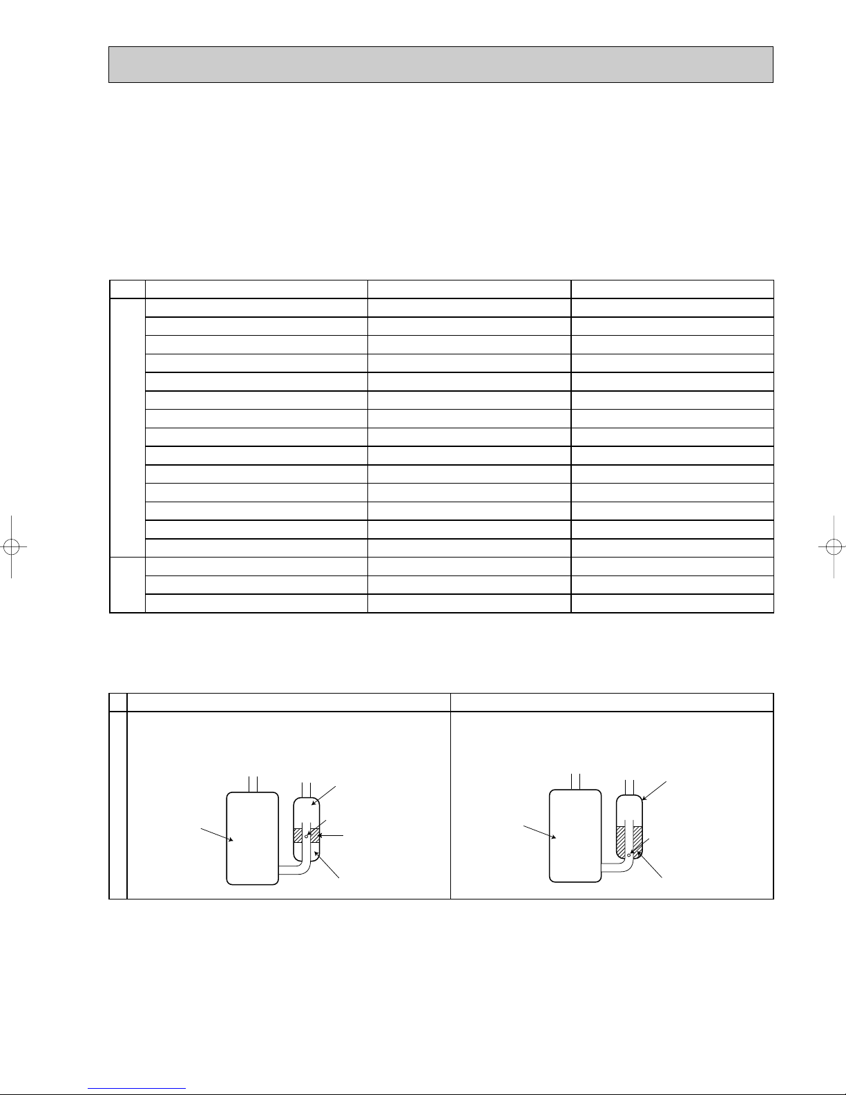
INFORMATION FOR THE AIR CONDITIONER WITH R410A REFRIGERANT
New Specification Current Specification
The incompatible refrigeration oil easily separates from
refrigerant and is in the upper layer inside the suction muffler.
Raising position of the oil back hole enables to back the
refrigeration oil of the upper layer to flow back to the
compressor.
Since refrigerant and refrigeration oil are compatible each,
refrigeration oil goes back to the compressor through the
lower position oil back hole.
Compressor
Suction muffler
Oil back hole
Refrigeration oil
Refrigerant
Compressor
Suction muffler
Oil back hole
Refrigeration oil /Refrigerant
Compressor
• This room air conditioner adopts HFC refrigerant (R410A) which never destroys the ozone layer.
• Pay particular attention to the following points, though the basic installation procedure is same as that for R22 air
conditioners.
1 As R410A has working pressure approximate 1.6 times as high as that of R22, some special tools and piping parts/
materials are required. Refer to the table below.
2 Take sufficient care not to allow water and other contaminations to enter the R410Arefrigerant during storage and
installation, since it is more susceptible to contaminations than R22.
3 For refrigerant piping, use clean, pressure-proof parts/materials specifically designed for R410A. (Refer to 2. Refrigerant
piping.)
4 Composition change may occur in R410A since it is a mixed refrigerant. When charging, charge liquid refrigerant to prevent
composition change.
NOTE : The unit of pressure has been changed to MPa on the international system of units(SI unit system).
The conversion factor is: 1(MPa [Gauge]) =10.2(kgf/
ff
3
[Gauge])
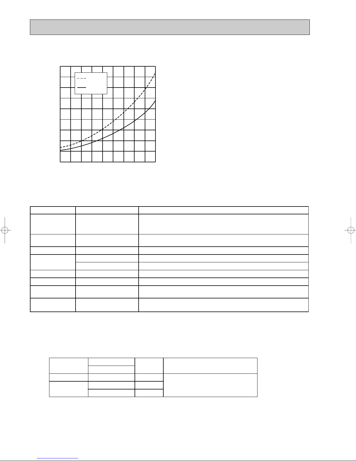
-30 -20 -10 0 10 20
30
40 50 60
-0.5
0.0
0.5
1.0
1.5
2.0
2.5
3.0
3.5
4.0
(MPa [Gauge])
R410A
R22
Conversion chart of refrigerant temperature and pressure
Saturated liquid pressure
(:)
NOTE : The unit of pressure has been changed to MPa on the
R410A tools Can R22 tools be used?
Gas leak detector
R410A has high pressures beyond the measurement range of existing
gauges. Port diameters have been changed to prevent any other refrigerant
from being charged into the unit.
Hose material and cap size have been changed to improve the pressure
resistance.
Dedicated for HFC refrigerant.
6.35 mm and 9.52 mm
Description
Clamp bar hole has been enlarged to reinforce the spring strength in the tool.
Provided for flaring work (to be used with R22 flare tool).
Provided to prevent the back flow of oil. This adapter enables you to use
vacuum pumps.
It is difficult to measure R410A with a charging cylinder because the
refrigerant bubbles due to high pressure and high-speed vaporization
No
No
No
Yes
Yes
New
New
New
Gauge manifold
Charge hose
Torque wrench
Flare tool
Flare gauge
Vacuum pump
adapter
Electronic scale for
refrigerant charging
No : Not Substitutable for R410A Yes : Substitutable for R410A
No 12.7 mm
Wall
thickness
Outside diameter
Pipe
mm
For liquid
For gas
6.35
9.52
12.7
0.8 mm
0.8 mm
0.8 mm
Heat resisting foam plastic
Specific gravity 0.045 Thickness 8 mm
Insulation material
international system of units(SI unit system).
The conversion factor is: 1(MPa [Gauge]) =10.2(kgf/ff[Gauge])
1.Tools dedicated for the air conditioner with R410A refrigerant
The following tools are required for R410A refrigerant. Some R22 tools can be substituted for R410A tools.
The diameter of the service port on the stop valve in outdoor unit has been changed to prevent any other refrigerant being
charged into the unit. Cap size has been changed from 7/16 UNF with 20 threads to 1/2 UNF with 20 threads.
1 Specifications
Use the refrigerant pipes that meet the following specifications.
• Use a copper pipe or a copper-alloy seamless pipe with a thickness of 0.8 mm. Never use any pipe with a thickness less
than 0.8mm, as the pressure resistance is insufficient.
2.Refrigerant piping
4

2 Flaring work and flare nut
Flaring work for R410A pipe differs from that for R22 pipe.
For details of flaring work, refer to Installation manual “FLARING WORK”.
Pipe diameter
mm
6.35
9.52
12.7
Dimension of flare nut
R410A
17
22
26
R22
17
22
24
3.Refrigerant oil
Apply the special refrigeration oil (accessories: packed with indoor unit) to the flare and the union seat surfaces.
4.Air purge
• Do not discharge the refrigerant into the atmosphere.
Take care not to discharge refrigerant into the atmosphere during installation, reinstallation, or repairs to the refrigerant
circuit.
• Use the vacuum pump for air purging for the purpose of environmental protection.
5.Additional charge
For additional charging, charge the refrigerant from liquid phase of the gas cylinder.
If the refrigerant is charged from the gas phase, composition change may occur in the refrigerant inside the cylinder and the
outdoor unit. In this case, ability of the refrigeration cycle decreases or normal operation can be impossible. However,
charging the liquid refrigerant all at once may cause the compressor to be locked. Thus, charge the refrigerant slowly.
Union
Stop valve
Indoor unit
Refrigerant gas
cylinder
operating valve
Liquid pipe
Gas pipe
Service port
Outdoor unit
Gauge manifold
valve (for R410A)
Charge hose (for R410A)
Refrigerant gas cylinder
for R410A with siphon
Refrigerant (liquid)
Electronic scale for refrigerant charging
5
1
Drain socket
1
2
Quick clean kit
1
MUZ-GA25VA -
E1
MUZ-GA35VA -
E1
–
1
MUZ-GA25VAH -
E1
MUZ-GA35VAH -
E1
2
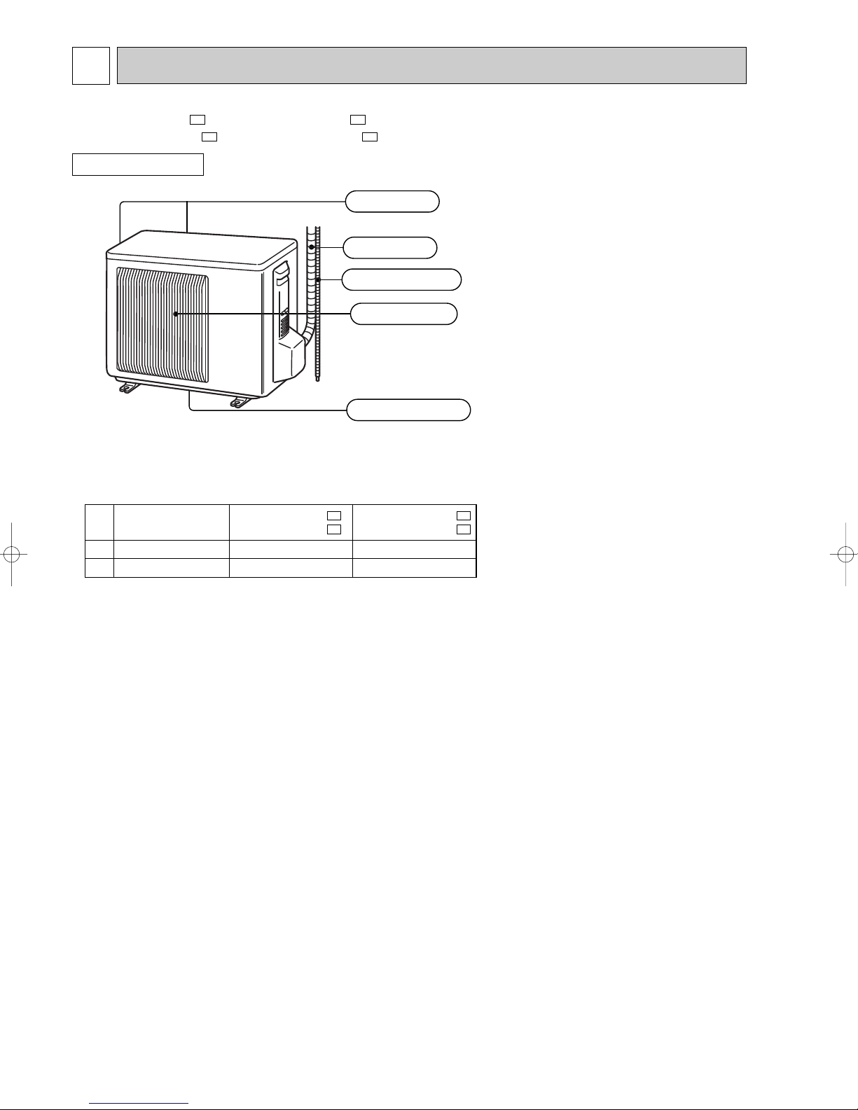
PART NAMES AND FUNCTIONS
MUZ-GA25VA - MUZ-GA35VA MUZ-GA25VAH - MUZ-GA35VAH -
OUTDOOR UNIT
(back and side)
ACCESSORIES
E1E1
E1E1
Air inlet
Piping
Drain hose
Air outlet
Drain outlet
6
3
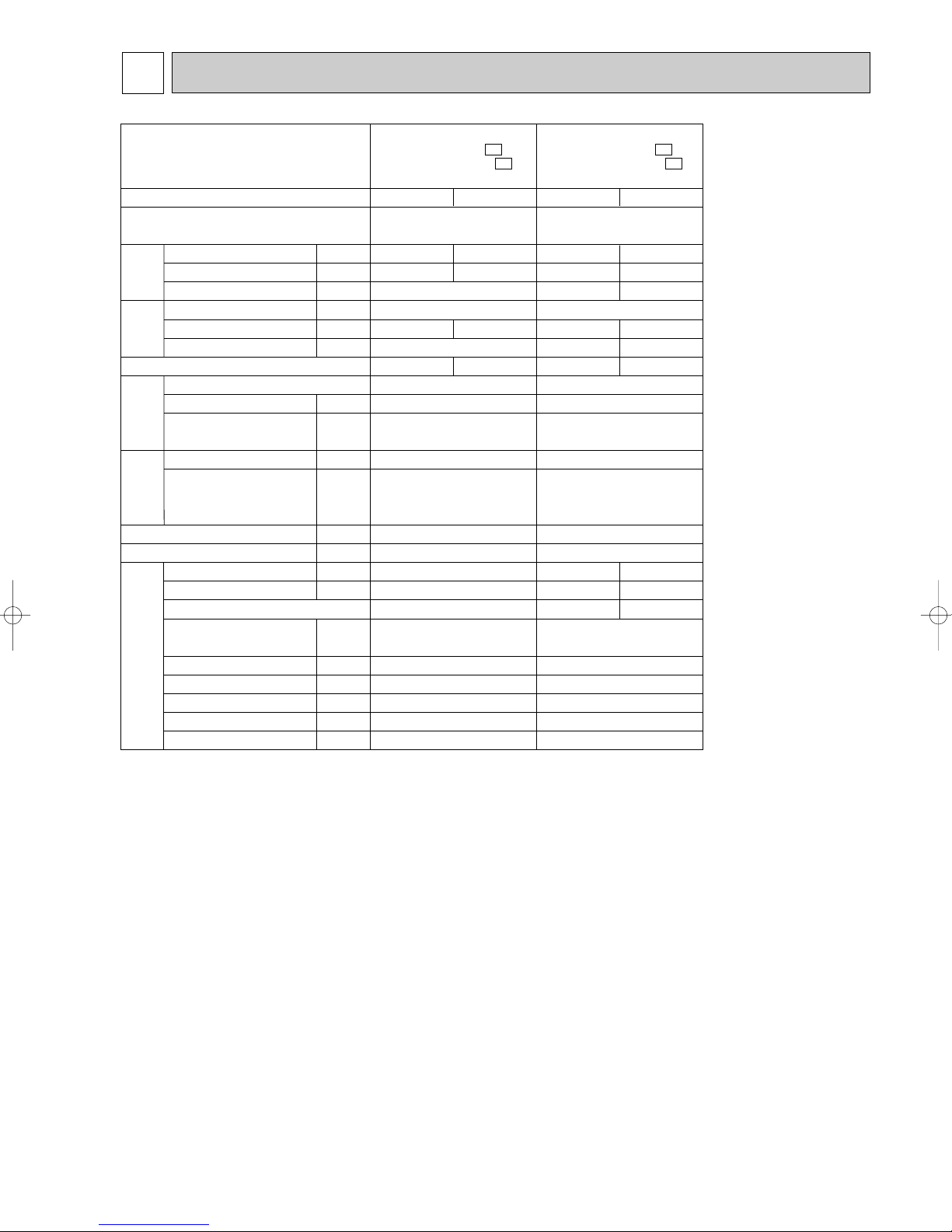
SPECIFICATION
Outdoor model
Function
Power supply
2.5 (0.9-3.0)
Capacity Rated frequency(Min.-Max.)
Dehumidification
Air flow ✽1
Capacity
Starting current ✽1
Compressor motor current ✽1
Fan motor current ✽1
Electrical
data
Coefficient of performance(C.O.P)
kW
r/h
K /h
A
A
A
✽1
Model
Output
Winding
resistance(at 20:)
Compressor
W
"
U-V 1.88
Model
Winding
Fan
motor
resistance(at 20:)
Dimensions WOHOD
Weight
Sound level ✽1
Fan speed(HighW/LowW, HighW/Med.W/LowW)
"
mm
kg
dB(A)
rpm
Fan speed regulator
Refrigerant filling
capacity(R410A)
Refrigeration oil (Model)
Special
remarks
Thermistor RT61
Thermistor RT62(at 100:)
Thermistor RT64(at 50:)
Thermistor RT65(at 25:)
(at 0:)
kg
cc
k"
k"
k"
k"
NOTE : Test conditions are based on ISO 5151
Cooling : Indoor Dry-bulb temperature 27:Wet-bulb temperature 19:
Outdoor Dry-bulb temperature 35:Wet-bulb temperature(24:)
Heating : Indoor Dry-bulb temperature 20: Wet-bulb temperature 15:
Outdoor Dry-bulb temperature 7: Wet-bulb temperature 6:
Refrigerant piping length (one way): 5m
✽1 Measured under rated operating frequency
w Reference value
MUZ-GA25VA MUZ-GA25VAH -
Cooling
Heating
Single phase
230V,50Hz
3.2 (0.9-4.5)
1.4
1,890
3.6
2.71
0.24
3.91
KNB065FDTH
500
U-W 1.88
V-W 1.88
RA6V21-AB
WHT-BLK 347
BLK-RED 281
800o550o285
31
46
810
1
0.85
320 (NEO22)
32.6
13.4
17
10
E1
—
3.11
4.21
E1
MUZ-GA35VA MUZ-GA35VAH -
Cooling
Single phase
230V,50Hz
3.5 (1.0-3.9)
2.0
2,058
5.0
4.44
0.31
3.24
KNB073FDVH
550
U-V 1.53
V-W 1.53
RC0J50-AL
WHT-BLK 37.5
BLK-RED 37.5
RED-WHT 37.5
800o550o285
33
47
810W/750
W
2
0.90
320 (NEO22)
32.6
13.4
17
10
E1
E1
Heating
4.0 (0.9-5.0)
—
2,178
4.20
0.35
3.79
U-W 1.53
48
880W/810W/650
3
W
7

OUTDOOR UNIT
Model
Item
Current transformer
Current transformer
Smoothing capacitor
Diode module
Fuse
Fuse
Defrost heater
Intelligent power module
Expansion valve coil
Reactor
Current-detecting resistor
Current-detecting resistor
Current-limiting resistor
Terminal block
Relay
Relay
Relay
Relay
R.V. coil
Solid state relay
Solenoid valve coil
Heater protector
Outdoor fan motor thermal fuse
MUZ-GA25VA
-
E1
(CT)
(CT761, CT781)
(
C63A, C63B, C63C
)
(DB61, DB65)
(F61)
(F71, F801)
(H)
(IPM)
(LEV)
(L61)
(R61)
(R831)
(
R64A, R64B
)
(TB1,TB2)
(X63)
(X64)
(X66)
(X69)
(21S4)
(SR61)
(21R1)
(26H)
MUZ-GA25VAH -
E1
MUZ-GA35VA -
E1
MUZ-GA35VAH -
E1
ETA19Z59BZ
ETQ19Z71AY
620+ 420V
D25XB60
250V 20A
250V 3.15A
PS21244-A-203
10A 23.0mH
25m" 5W
10" 5W
3P
G5NB-1a
G4A-1A-PS
—
—
—
230V 130W
G5NB-1a
Open 45:
—
—
—
230V 130W
G5NB-1a
Open 45:
45m" 5W (1 element)
CAM-MD12ME 12VDC
—
STF-01AJ503
—
—
—
—
G5NB-1a
SHF-4-10W5
G3MC-202PL
FQ-208-RK
Open 152:
Specifications and rating conditions of main electric parts
8
4
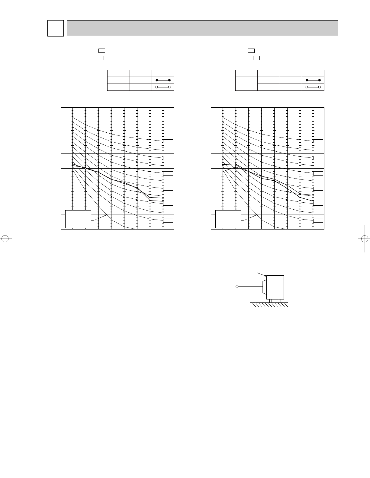
90
80
70
60
50
40
30
20
10
63 125 250 500 1000 2000 4000 8000
NC-60
NC-50
NC-40
NC-30
NC-20
NC-70
OCTAVE BAND SOUND PRESSURE LEVEL, dB re 0.0002 MICRO BAR
BAND CENTER FREQUENCIES, Hz
Test conditions,
Cooling : Dry-bulb temperature 35: Wet-bulb temperature (24:)
APPROXIMATE
THRESHOLD OF
HEARING FOR
CONTINUOUS
NOISE
COOLING
FUNCTION
SPL(dB(A)) LINE
HEATING
46
46
Heating : Dry-bulb temperature 7: Wet-bulb temperature 6:
NOISE CRITERIA CURVES
MUZ-GA25VA MUZ-GA25VAH -
E1
E1
MUZ-GA35VA MUZ-GA35VAH -
Test conditions,
Cooling : Dry-bulb temperature 35: Wet-bulb temperature (24:)
Heating : Dry-bulb temperature 7: Wet-bulb temperature 6:
90
80
70
60
50
40
30
APPROXIMATE
20
THRESHOLD OF
HEARING FOR
CONTINUOUS
NOISE
OCTAVE BAND SOUND PRESSURE LEVEL, dB re 0.0002 MICRO BAR
10
63 125 250 500 1000 2000 4000 8000
E1
E1
SPL(dB(A))
High
Med.
FUNCTION
COOLING
HEATING
FAN SPEED
BAND CENTER FREQUENCIES, Hz
LINE
47
48
NC-70
NC-60
NC-50
NC-40
NC-30
NC-20
OUTDOORUNIT
1m
MICROPHONE
9
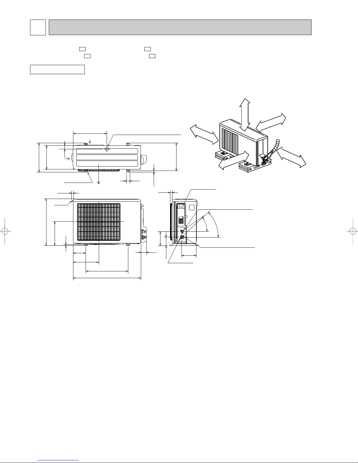
5
10
69
800
302.5
500 Bolt pitch for installation
150
22.3
Handle
550
280
164.5
99.5
170.5
23
Service panel
Service port
285
344.5
44
400
Air in
Air out
Air in
17.5
Bolt pitch for
installation
304~325
40
Liquid refrigerant pipe joint
Refrigerant pipe (flared) [6.35
Gas refrigerant pipe joint
Refrigerant pipe (flared) [9.52
43-
35-
2 holes 10X21
Drain hole [33 (MUZ-GA25/GA35VAH)
REQUIRED SPACE
Basically open 100mm or more
without any obstruction in front
and on both sides of the unit.
350mm or more
200mm or more
100mm or more
100mm or more
Open two sides of left,
right, or rear side.
Drain hole [42 (MUZ-GA25/GA35VA)
OUTLINES AND DIMENSIONS
MUZ-GA25VA - MUZ-GA35VA MUZ-GA25VAH - MUZ-GA35VAH -
OUTDOOR UNIT
E1E1
E1E1
Unit: mm
10
6
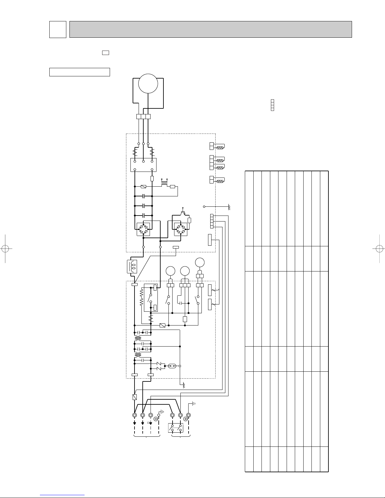
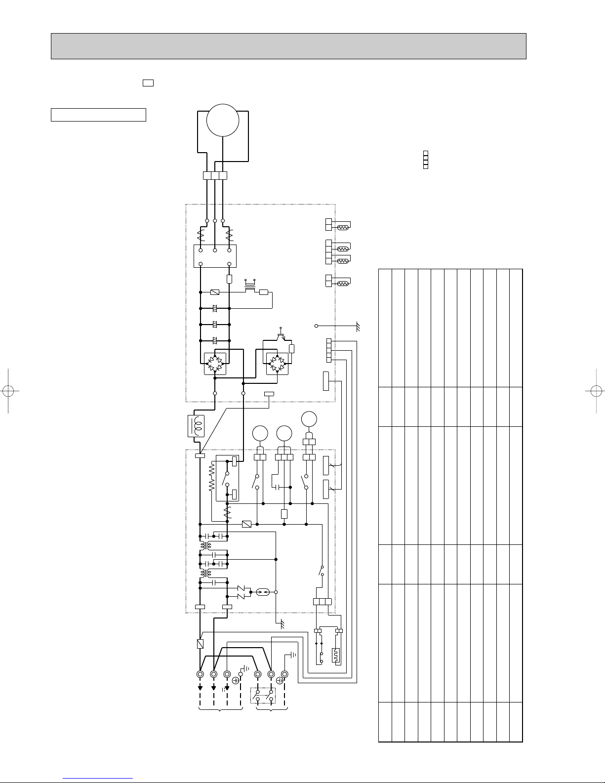
WIRING DIAGRAM
MUZ-GA25VA -
OUTDOOR UNIT
E1
MODEL WIRING DIAGRAM
W
REDRED
2
WHT
LD-V
V
F801
MC
3
N
C63C
C63B
C63A
CN61
LD-W
W
R61
V
WHT
CT781
IPM
T801
BLK
U
BLK
LD-U
U
P
1
CT761
+ + +
IC801
CN642
21 3 4
CN641
21 21
CN643
INVERTER P.C. BOARD
R831
LDY
54321
CN601
TR821
RT64
RT62RT61
RT65
GRN
the indoor unit electric wiring diagram for
servicing.
2.Use copper conductors only. (For field wiring)
3. Symbols below indicate.
/: Terminal block, : Connector
NOTE:1. About the indoor side electric wiring refer to
NAME
BLK
L61
BLK
TB2
DB61
TAB63
R64A
R64B
L63
L62
TAB61
WHT
F61
WHT
230V~
X64
TAB62
BLU
S2S1S3
LD70
RED
V
12-24
LD69
TB800
BLK
BLU
21S4
2
1
CN721
3
4
CT
CONNECTING
TO INDDOR UNIT
CN771
X63
C65
F71
SR61
NR63NR64
DSA61
GRN
TB1
L
N
CIRCUIT BREAKER
~/N
DB65
MF
2
321
2
CN923
X69
LDE
GRN/YLW
PE
POWER
SUPPLY
230V 50Hz
21R1
1
1
CN726 CN725
6 4
CN727
WHITE
BLU
POWER P.C. BOARD
RED
CURRENT-DETECTING RESISTOR
CURRENT-LIMITING RESISTOR
SOLID STATE RELAY
R61,R831
R64A,R64B
SYMBOL
SR61
NAME
REACTOR
CMC COIL
COMPRESSOR
SYMBOL
L61
L62,L63MCMF
NAME
CURRENT TRANSFORMER
SMOOTHING CAPACITOR
OUTDOOR FAN CAPACITOR
TERMINAL BLOCK
SWITCHING POWER TRANSISTOR
TRANSFORMER
RELAY
R.V. COIL
TB1,TB2
TR821
T801
X63,X64,X69
21S4
OUTDOOR FAN MOTOR(INNER FUSE)
VARISTOR
DEFROST THERMISTOR
DISCHARGE TEMPERATURE THERMISTOR
FIN TEMPERATURE THERMISTOR
NR63,NR64
RT61
RT62
RT64
DIODE MODULE
SURGE ABSORBER
FUSE (T20AL250V)
FUSE (T3.15AL250V)
INTELLIGENT POWER DEVICE
SOLENOID VALVE COIL
21R1
AMBIENT TEMPERATURE THERMISTOR
RT65
INTELLIGENT POWER MODULE
11
SYMBOL
CT,CT761,CT781
C63A,C63B,C63C
C65
DB61,DB65
DSA61
F61
F71,F801
IC801
IPM
MUZ-GA25VAH -
PE
CIRCUIT BREAKER
~/N
230V 50Hz
POWER
SUPPLY
230V~
12-24
V
TO INDDOR UNIT
CONNECTING
RED
BLU
WHITE
GRN/YLW
TB1
L
N
R64A
TB2
S3
S1
S2
RED
BLU
WHT
R64B
WHT
H
26H
+ + +
CT
3
4
NR64 NR63
GRN
DSA61
LDE
LDY
GRN
X69
1
2
CN771
21R1
CN923
2
1
46
CN725CN727 CN726
C65
SR61
312
MF
312
X66
CN722
1
2
YLW
BLK BLK
BLKBLK
BLK
BLK
1
2
BLK
RED
21
2 31
CN601
4 5
43 1 21 2
TB800
RT65 RT64RT62RT61
POWER P.C. BOARD
CN643
CN641
INVERTER P.C. BOARD
CN642
21S4
X63
CN721
1
2
IC801
F801
C63C
LD-V
LD-W
LD-U
3
1
WHT
BLK
RED RED
V
BLK
WHT
W
U
MC
CN61
IPM
CT781
CT761
2
R61
N
U
V
W
P
L61
BLK
R831
TAB63
LD69
DB65
DB61
LD70
TR821
C63B
C63A
BLK
T801
L63
F61
TAB61
L62
X64
F71
TAB62
BLK
BLU
OUTDOOR UNIT
E1
MODEL WIRING DIAGRAM
the indoor unit electric wiring diagram for
servicing.
2.Use copper conductors only. (For field wiring)
3. Symbols below indicate.
/: Terminal block, : Connector
NOTE:1. About the indoor side electric wiring refer to
NAME
CURRENT-LIMITING RESISTOR
SOLID STATE RELAY
TERMINAL BLOCK
SWITCHING POWER TRANSISTOR
TRANSFORMER
RELAY
R.V. COIL
SOLENOID VALVE COIL
HEATER PROTECTOR
SYMBOL
R64A,R64B
SR61
TB1,TB2
TR821
T801
X63,X64,X66,X69
21S4
21R1
26H
NAME
REACTOR
OUTDOOR FAN MOTOR(INNER FUSE)
CMC COIL
VARISTOR
COMPRESSOR
DEFROST THERMISTOR
DISCHARGE TEMPERATURE THERMISTOR
FIN TEMPERATURE THERMISTOR
AMBIENT TEMPERATURE THERMISTOR
CURRENT-DETECTING RESISTOR
12
SYMBOL
L61
L62,L63MCMF
NAME
CURRENT TRANSFORMER
SMOOTHING CAPACITOR
OUTDOOR FAN CAPACITOR
SYMBOL
CT,CT761,CT781
C63A,C63B,C63C
C65
NR63,NR64
RT61
RT62
RT64
DIODE MODULE
SURGE ABSORBER
FUSE (T20AL250V)
FUSE (T3.15AL250V)
DEFROST HEATER
DB61,DB65
DSA61
F61
F71,F801HIC801
RT65
R61,R831
INTELLIGENT POWER DEVICE
INTELLIGENT POWER MODULE
IPM

MUZ-GA35VA -
E1
MODEL WIRING DIAGRAM
OUTDOOR UNIT
BLK
L61
BLK
U
BLK
BLK
LD-U
U
DB61
TAB63
R64A
R64B
W
1
2
WHT
LD-V
CT761
V
P
F801
+ + +
MC
3
RED RED
N
C63C
C63B
C63A
LD70
X64
CN61
LD-W
W
R61
BLK
3
4
V
WHT
CT781
IPM
T801
LD69
BLU
LEV
6
CN724
IC801
TB800
21S4
1
X63
CN642
CN641
CN643
INVERTER P.C. BOARD
TR821
2
CN721
DB65
6
CN727CN72
R831
CN931 CN932
LDY
CN601
CN725
4
the indoor unit electric wiring diagram for
servicing.
2.Use copper conductors only. (For field wiring)
3. Symbols below indicate.
/: Terminal block, : Connector
43 1 21 2
21
RT65 RT64RT62RT61
2
5 1 3
5
3
31
2 4
2 4
1
GRN
4 5
2 31
6
NOTE:1. About the indoor side electric wiring refer to
MF
NAME
CURRENT-DETECTING RESISTOR
CURRENT-LIMITING RESISTOR
TERMINAL BLOCK
SWITCHING POWER TRANSISTOR
TRANSFORMER
SYMBOL
R61,R831
R64A,R64B
TB1,TB2
TR821
T801
RELAY
R.V. COIL
X63,X64
21S4
L63
L62
TAB61
WHT
F61
WHT
TB2
S1
230V~
BLU
S2
TAB62
RED
S3
V
12-24
CT
F71
NR63
DSA61
NR64
GRN
TB1
L
N
CONNECTING
TO INDDOR UNIT
CIRCUIT BREAKER
~/N
230V 50Hz
LDE
GRN/YLW
PE
POWER
SUPPLY
13
NAME
POWER P.C. BOARD
SYMBOL
WHITE
BLU
RED
NAME
SYMBOL
REACTOR
CMC COIL
COMPRESSOR
OUTDOOR FAN MOTOR
VARISTOR
L61
L62,L63MCMF
CURRENT TRANSFORMER
SMOOTHING CAPACITOR
CT,CT761,CT781
C63A,C63B,C63C
NR63,NR64
DIODE MODULE
SURGE ABSORBER
FUSE (T20AL250V)
DB61,DB65
DSA61
F61
DISCHARGE TEMPERATURE THERMISTOR
FIN TEMPERATURE THERMISTOR
DEFROST THERMISTOR
RT61
FUSE (T3.15AL250V)
F71,F801
AMBIENT TEMPERATURE THERMISTOR
RT62
RT64
RT65
INTELLIGENT POWER DEVICE
INTELLIGENT POWER MODULE
EXPANSION VALVE COIL
IC801
IPM
LEV

MUZ-GA35VAH -
PE
CIRCUIT BREAKER
~/N
230V 50Hz
POWER
SUPPLY
230V~
TO INDDOR UNIT
CONNECTING
RED
BLU
WHITE
GRN/YLW
TB1
L
N
R64A
TB2
S3
S1
S2
RED
BLU
WHT
R64B
WHT
H
26H
+ + +
CT
4
3
NR64 NR63
GRN
DSA61
LDE
2 31 4 5
CN601
LDY
GRN
MF
RT65 RT64RT62RT61
31
2 4
5
21
3
2
1
2 4
5
1
3
CN931 CN932
43 1 21 2
CN643
CN641
CN642
312
X66
CN722
1
2
YLW
BLK BLK
BLKBLK
BLK
BLK
1
2
BLK
RED
6
4
CN727CN72
6
CN725
TB800
POWER P.C. BOARD
INVERTER P.C. BOARD
21S4
X63
CN721
1
2
IC801
F801
C63C
LD-V
LD-W
LD-U
3
1
WHT
BLK
RED RED
V
BLK
WHT
W
U
MC
CN61
IPM
CT781
CT761
2
CN724
LEV
6
R61
N
U
V
W
P
L61
BLK
R831
TAB63
LD69
DB65
DB61
LD70
TR821
C63B
C63A
BLK
T801
L63
F61
TAB61
L62
X64
F71
TAB62
BLK
BLU
12-24
V
OUTDOOR UNIT
E1
MODEL WIRING DIAGRAM
the indoor unit electric wiring diagram for
servicing.
2.Use copper conductors only. (For field wiring)
3. Symbols below indicate.
/: Terminal block, : Connector
NOTE:1. About the indoor side electric wiring refer to
NAME
CURRENT-LIMITING RESISTOR
TERMINAL BLOCK
SYMBOL
R64A,R64B
TB1,TB2
SWITCHING POWER TRANSISTOR
TRANSFORMER
RELAY
R.V. COIL
TR821
T801
X63,X64,X66
21S4
HEATER PROTECTOR
26H
14
NAME
REACTOR
CMC COIL
COMPRESSOR
SYMBOL
L61
L62,L63MCMF
NAME
CURRENT TRANSFORMER
SMOOTHING CAPACITOR
DIODE MODULE
SYMBOL
CT,CT761,CT781
C63A,C63B,C63C
DB61,DB65
DISCHARGE TEMPERATURE THERMISTOR
OUTDOOR FAN MOTOR
VARISTOR
NR63,NR64
SURGE ABSORBER
FUSE (T20AL250V)
DSA61
F61
FIN TEMPERATURE THERMISTOR
DEFROST THERMISTOR
RT61
RT62
RT64
FUSE (T3.15AL250V)
DEFROST HEATER
INTELLIGENT POWER DEVICE
F71,F801HIC801
AMBIENT TEMPERATURE THERMISTOR
CURRENT-DETECTING RESISTOR
RT65
R61,R831
INTELLIGENT POWER MODULE
EXPANSION VALVE COIL
IPM
LEV
7
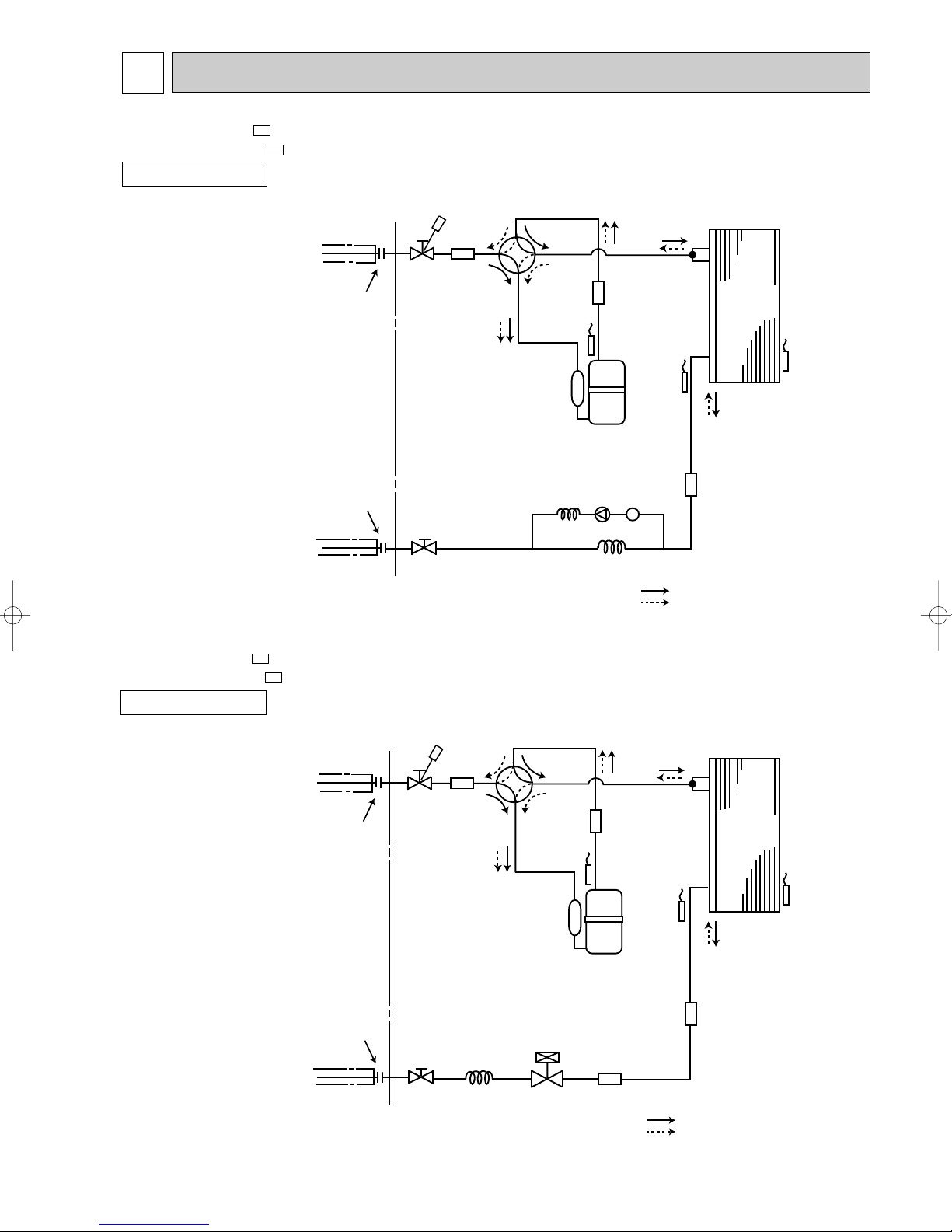
Outdoor
heat
exchanger
Flared connection
Defrost
thermistor
RT61
Discharge
temperatuer
thermistor
RT62
Flared connection
Stop valve
(with strainar)
Stop valve
(with service port)
Refrigerant flow in cooling
Compressor
Muffler
Muffler
4-way valve
Refrigerant flow in heating
Refrigerant pipe [9.52
(with heat insulator)
Refrigerant pipe [6.35
(with heat insulator)
R.V. coil
heating ON
cooling OFF
Strainer
#100
Capillary tube
[3.0✕[1.4✕800
Check
valve
Capillary tube
[3.0✕[1.4✕500
Solenoid
valve
Ambient
temperature
thermistor
RT65
Outdoor
heat
exchanger
Flared connection
Defrost
thermistor
RT61
Discharge
temperatuer
thermistor
RT62
Flared connection
Stop valve
(with strainar)
Stop valve
(with service port)
Capillary tube
[3.0✕[2.0✕240
Refrigerant flow in cooling
Compressor
4-way valve
Refrigerant flow in heating
Refrigerant pipe [9.52
(with heat insulator)
Refrigerant pipe [6.35
(with heat insulator)
Expansion
valve
R.V. coil
heating ON
cooling OFF
Strainer
#100
Muffler
Ambient
temperature
thermistor
RT65
Muffler
Muffler
REFRIGERANT SYSTEM DIAGRAM
MUZ-GA25VA MUZ-GA25VAH -
OUTDOOR UNIT
E1
E1
Unit:mm
MUZ-GA35VA MUZ-GA35VAH -
E1
E1
OUTDOOR UNIT
15
Unit:mm
Outdoor unit
precharged
850
900
14m
270
270
7m
0
0
6m
0
0
5m
0
0
11m
180
180
Model
Refrigerant piping length (one way)
Calculation : Xg=30g/mo(Refrigerant piping length(m) - 5)
8m
90
90
9m
120
120
10m
150
150
12m
210
210
13m
240
240
15m
300
300
20m
450
450
MUZ-GA25VA - E1
MUZ-GA25VAH -
E1
MUZ-GA35VA - E1
MUZ-GA35VAH - E1
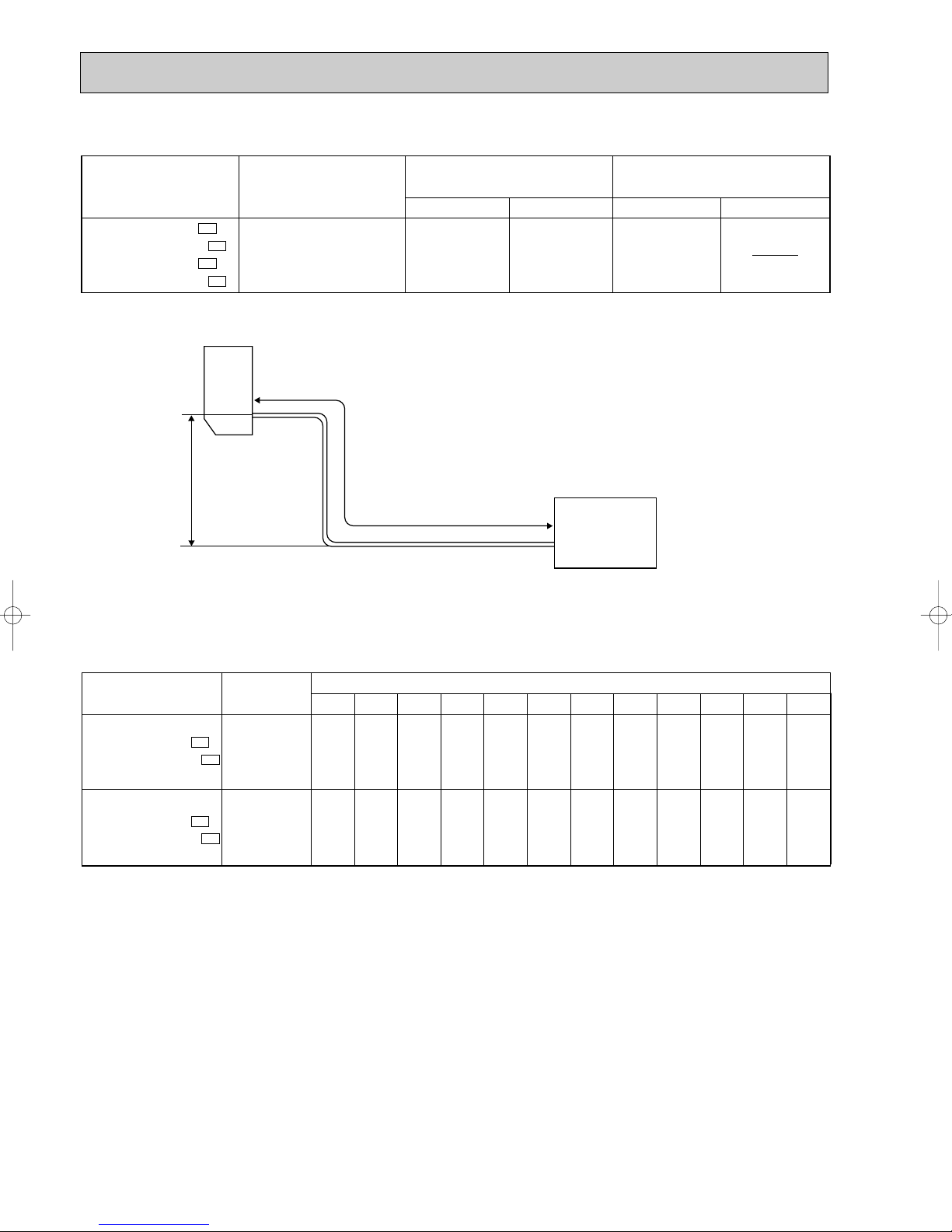
Refrigerant Piping
Max. length
A
w Height difference should be within 12m regardless of which unit, indoor or outdoor position is high.
w Max. Height
difference 12m
Indoor
unit
Outdoor unit
MAX. REFRIGERANT PIPING LENGTH
Refrigerant piping
Max. length : m
A
20
Indoor unit
Gas 0.43
Liquid 0.5
Gas
9.52
Liquid
6.35
Outdoor unit
Piping size O.D : mm Length of connecting pipe : m
Model
MUZ-GA25VA -
E1
MUZ-GA25VAH -
E1
MUZ-GA35VA -
E1
MUZ-GA35VAH -
E1
MAX. HEIGHT DIFFERENCE
ADDITIONAL REFRIGERANT CHARGE (R410A:g)
16
 Loading...