

Mitsubishi Electric MUZ-FH25VE - E1, MUZ-FH35VE - E1, MUZ-FH50VE - E1, MUZ-FH25VE, MUZ-FH35VE Service Manual
...
SERVICE MANUAL
CONTENTS
1. TECHNICAL CHANGES ··································· 3
2. PART NAMES AND FUNCTIONS ····················· 3
3. SPECIFICATION ················································ 4
4. NOISE CRITERIA CURVES ······························ 7
5. OUTLINES AND DIMENSIONS ························ 8
6. WIRING DIAGRAM ············································ 9
7. REFRIGERANT SYSTEM DIAGRAM ··············11
8. PERFORMANCE CURVES ····························· 13
9. ACTUA TOR CONTROL ··································· 24
10. SERVICE FUNCTIONS ···································· 25
11. TROUBLESHOOTING ····································· 26
12. DISASSEMBLY INSTRUCTIONS ···················· 47
Models
SPLIT-TYPE AIR CONDITIONERS
NOTE:
RoHS compliant products have <G> mark on the spec name plate.
HFC
utilized
R410A
No. OBH624
REVISED EDITION-A
OUTDOOR UNIT
Indoor unit service manual
MSZ-FH•VE Series (OBH623)
PARTS CATALOG (OBB624)
MUZ-FH25VE
-
E1
MUZ-FH35VE
-
E1
MUZ-FH50VE
-
E1
Please void OBH624.
Revision A:
•
MUZ-FH50VE- E1 has been added.
MUZ-FH25VE
MUZ-FH35VE

2
<Preparation before the repair service>
Prepare the proper tools.
Prepare the proper protectors.
Provide adequate ventilation.
After stopping the operation of the air conditioner, turn off the power-supply breaker and remove the power plug.
Discharge the capacitor before the work involving the electric parts.
<Precautions during the repair service>
Do not perform the work involving the electric parts with wet hands.
Do not pour water into the electric parts.
Do not touch the refrigerant.
Do not touch the hot or cold areas in the refrigeration cycle.
When the repair or the inspection of the circuit needs to be done without turning off the power, exercise great caution not to
touch the live parts.
Use the specifi ed refrigerant only
Never use any refrigerant other than that specified.
Doing so may cause a burst, an explosion, or fire when the unit is being used, serviced, or disposed of.
Correct refrigerant is specified in the manuals and on the spec labels provided with our products.
We will not be held responsible for mechanical failure, system malfunction, unit breakdown or accidents caused by
failure to follow the instructions.
Revision A:
•
MUZ-FH50VE-
E1
has been added.
OBH624A
3
MUZ-FH25VE -
E1
MUZ-FH35VE -
E1
MUZ-FH50VE -
E1
1. New model
TECHNICAL CHANGES
1
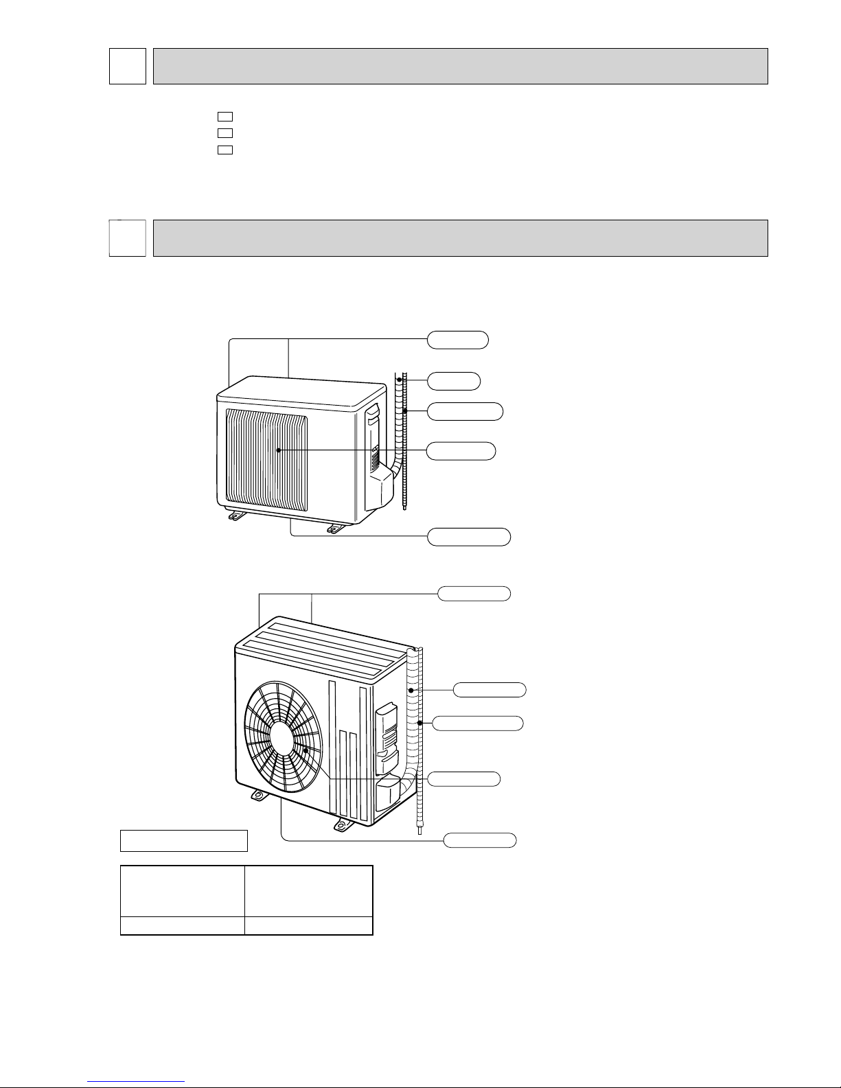
Air outlet
Drain outlet
Piping
Drain hose
Air inlet
(back and side)
MUZ-FH25VE
MUZ-FH35VE
PART NAMES AND FUNCTIONS
2
ACCESSORIES
Model
MUZ-FH25VE
MUZ-FH35VE
MUZ-FH50VE
Drain socket 1
MUZ-FH50VE
Piping
Air outlet
Drain outlet
Air inlet
(back and side)
Drain hose
OBH624A
4
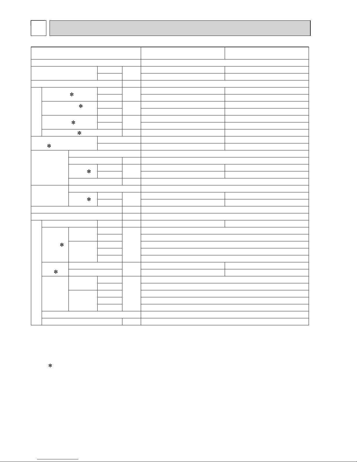
Outdoor model MUZ-FH25VE MUZ-FH35VE
Power supply Single phase, 230 V, 50 Hz
Capacity
Rated frequency (Min.-Max.)
Cooling
kW
2.5 (1.4 - 3.5) 3.5 (0.8 - 4.0)
Heating 3.2 (1.8 - 5.5) 4.0 (1.0 - 6.3)
Breaker Capacity A 10
Electrical data
Power input 1 (Total)
Cooling
W
485 820
Heating 580 800
Running current 1
(Total)
Cooling
A
2.6 3.9
Heating 2.9 3.8
Power factor 1 (Total)
Cooling
%
81 91
Heating 86 91
Starting current
1 (Total) A 2.9 3.9
Coeffi cient of performance
(COP)
1 (Total)
Cooling 5.15 4.27
Heating 5.52 5.00
Compressor
Model SNB140FRUMT
Output W 950
Current 1
Cooling
A
2.04 3.32
Heating 2.34 3.22
Refrigeration oil (Model) L 0.35 (FV50S)
Fan motor
Model RC0J50-CI
Current 1
Cooling
A
0.28 0.30
Heating 0.28 0.30
Dimensions W × H × D mm 800 × 550 × 285
Weight kg 37
Special remarks
Dehumidifi cation Cooling L/h 0.2 0.8
Air fl ow 1
Cooling
High
m3/h
1,806
Low 1,038
Heating
High 2,016
Med. 1,710
Low 1,326
Sound
level 1
Cooling
dB(A)
46 49
Heating 49 50
Fan speed
Cooling
High
rpm
810
Low 490
Heating
High 900
Med. 770
Low 610
Fan speed regulator 3
Refrigerant fi lling capacity (R410A) kg 1.15
NOTE: Test conditions are based on ISO 5151.
Cooling: Indoor Dry-bulb temperature 27°C Wet-bulb temperature 19°C
Outdoor Dry-bulb temperature 35°C
Heating: Indoor Dry-bulb temperature 20°C
Outdoor Dry-bulb temperature 7°C Wet-bulb temperature 6°C
Refrigerant piping length (one way): 5 m
1 Measured under rated operating frequency.
SPECIFICATION
3
OBH624A
5
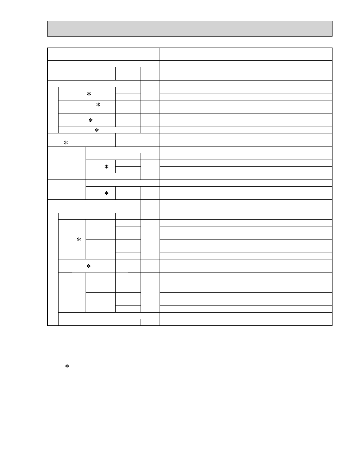
Outdoor model MUZ-FH50VE
Power supply Single phase, 230 V, 50 Hz
Capacity
Rated frequency (Min. - Max.)
Cooling
kW
5.0 (1.9 - 6.0)
Heating 6.0 (1.7 - 8.7)
Breaker Capacity A 16
Electrical data
Power input 1 (Total)
Cooling
W
1,380
Heating 1,480
Running current 1
(Total)
Cooling
A
6.1
Heating 6.5
Power factor
1 (Total)
Cooling
%
98
Heating 98
Starting current 1 (Total) A 6.5
Coeffi cient of performance
(COP) 1 (Total)
Cooling 3.62
Heating 4.05
Compressor
Model SNB172FEKMT
Output W 1,200
Current 1
Cooling
A
4.98
Heating 5.37
Refrigeration oil (Model) L 0.40(FV50S)
Fan motor
Model RC0J60-BC
Current
1
Cooling
A
0.83
Heating 0.84
Dimensions W × H × D mm 840 × 880 × 330
Weight kg 55
Special remarks
Dehumidifi cation Cooling L/h 2.0
Air fl ow 1
Cooling
High
m3/h
3,006
Med. 3,006
Low 1,626
Heating
High 2,892
Med. 2,892
Low 2,280
Sound level 1
Cooling
dB(A)
51
Heating 54
Fan speed
Cooling
High
rpm
840
Med. 840
Low 480
Heating
High 810
Med. 810
Low 650
Fan speed regulator 3
Refrigerant fi lling capacity (R410A) kg 1.55
NOTE: Test conditions are based on ISO 5151.
Cooling: Indoor Dry-bulb temperature 27°C Wet-bulb temperature 19°C
Outdoor Dry-bulb temperature 35°C
Heating: Indoor Dry-bulb temperature 20°C
Outdoor Dry-bulb temperature 7°C Wet-bulb temperature 6°C
Refrigerant piping length (one way): 5 m
1 Measured under rated operating frequency.
OBH624A
6
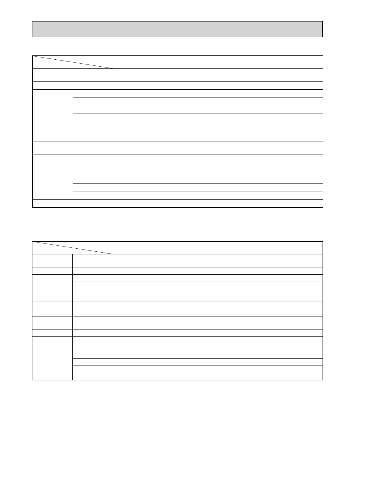
Specifi cations and rated conditions of main electric parts
Model
Item
MUZ-FH25VE MUZ-FH35VE
Smoothing
capacitor
(C61, C62) 600 μF/ 620 μF 420 V
Diode module (DB61) 15 A 600 V
Fuse
(F61) T20AL250V
(F701, F801, F901)
T3.15AL250V
Power module
(IC700) 15 A 600 V
(IC932) 8A600V
Expansion valve
coil
(LEV) 12 V DC
Reactor (L61) 23 mH
Power factor
controller
(IC820) 20A 600V
Circuit
protection
(PTC64, PTC65) 33 Ω
Terminal block (TB) 5 P
Relay
(X63) 3 A 250 V
(X64) 20 A 250 V
(X69) 10A 230V
R.V.coil (21S4) 220 - 240 V AC
Specifi cations and rated conditions of main electric parts
Model
Item
MUZ-FH50VE
Smoothing
capacitor
(CB1, CB2, CB3)
560 μF 450 V
Fuse
(F601, F880, F901)
T3.15AL250 V
IGBT module
(IC932) 5 A 600 V
(IC700) 20 A 600 V
Expansion valve
coil
(LEV) 12 V DC
Reactor (L) 340 μH
Diode module (IC820) 20 A 600 V
Circuit
protection
(PTC64, PTC65) 33 Ω
Terminal block (TB1, TB2) 3 P
Relay
(X64) 20 A 250 V
(X65) 20 A 250 V
(X69) 10 A 250 V
(X601) 3 A 250 V
(X602) 3 A 250 V
R.V. coil (21S4) 220 - 240 V AC
OBH624A
7
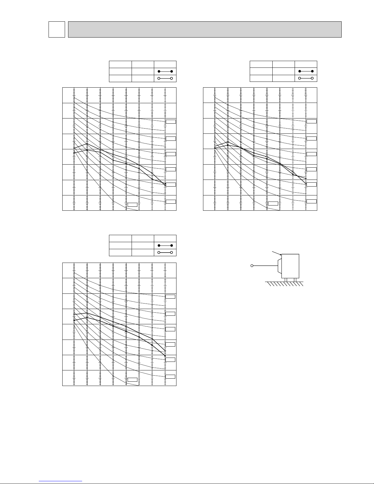
90
80
70
60
50
40
30
20
10
63 125 250 500 1000 2000 4000 8000
NC-60
NC-50
NC-40
NC-30
NC-20
NC-70
OCTAVE BAND SOUND PRESSURE LEVEL, 0dB re 0.0002 MICRO BAR
BAND CENTER FREQUENCIES, Hz
COOLING
FUNCTION
SPL(dB(A)) LINE
HEATING
46
49
NC-10
MUZ-FH25VE
90
80
70
60
50
40
30
20
10
63 125 250 500 1000 2000 4000 8000
NC-60
NC-50
NC-40
NC-30
NC-20
NC-70
OCTAVE BAND SOUND PRESSURE LEVEL, dB re 0.0002 MICRO BAR
BAND CENTER FREQUENCIES, Hz
COOLING
FUNCTION
SPL(dB(A))
LINE
HEATING
49
50
NC-10
MUZ-FH35VE
NOISE CRITERIA CURVES
4
Test conditions
Cooling: Dry-bulb temperature 35°C
Heating: Dry-bulb temperature 7°C Wet-bulb temperature 6°C
OUTDOOR UNIT
MICROPHONE
1 m
MUZ-FH50VE
90
80
70
60
50
40
30
20
10
63 125 250 500 1000 2000 4000 8000
NC-60
NC-50
NC-40
NC-30
NC-20
NC-70
OCTAVE BAND SOUND PRESSURE LEVEL, 0dB re 0.0002 MICRO BAR
BAND CENTER FREQUENCIES, Hz
COOLING
FUNCTION
SPL(dB(A)) LINE
HEATING
51
NC-10
54
OBH624A
8
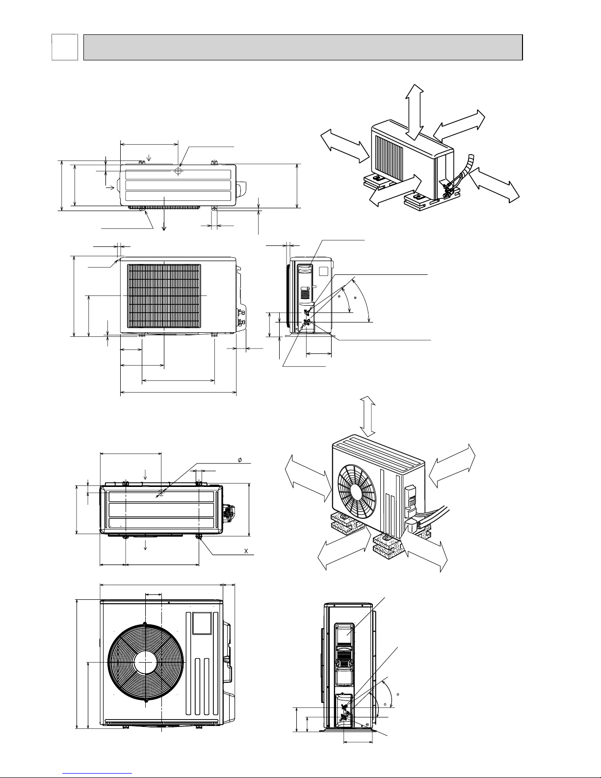
10
69
800
302.5
500 Bolt pitch for installation
150
22.3
Handle
550
280
164.5
99.5
170.5
23
Service panel
Service port
285
344.5
44
400
Air in
Air out
Air in
17.5
Bolt pitch for
installation
304~325
40
Liquid refrigerant pipe joint
Refrigerant pipe (flared) ø6.35
Gas refrigerant pipe joint
Refrigerant pipe (flared) ø9.52
43
35
2 holes 10 X 21
REQUIRED SPACE
100 mm or more
350 mm or more
200 mm or more
100 mm or more
100 mm or more
Drain hole ø42
Unit: mm
MUZ-FH25VE
MUZ-FH35VE
OUTLINES AND DIMENSIONS
5
MUZ-FH50VE
417.5
40
42
Drain hole
175
500
330
50
Air in
Air out
2-holes 10 21
360
840
109
81
880
452
Service panel
99.5
164.5
195
35
44
Liquid refrigerant
pipe joint
Refrigerant pipe
(flared)
Ø 6.35
Gas refrigerant pipe joint
Refrigerant pipe
(flared)
Ø 12.7
350 mm or more
100 mm or more
REQUIRED SPACE
500 mm or more
100 mm or more
500 mm or more
OBH624A
9
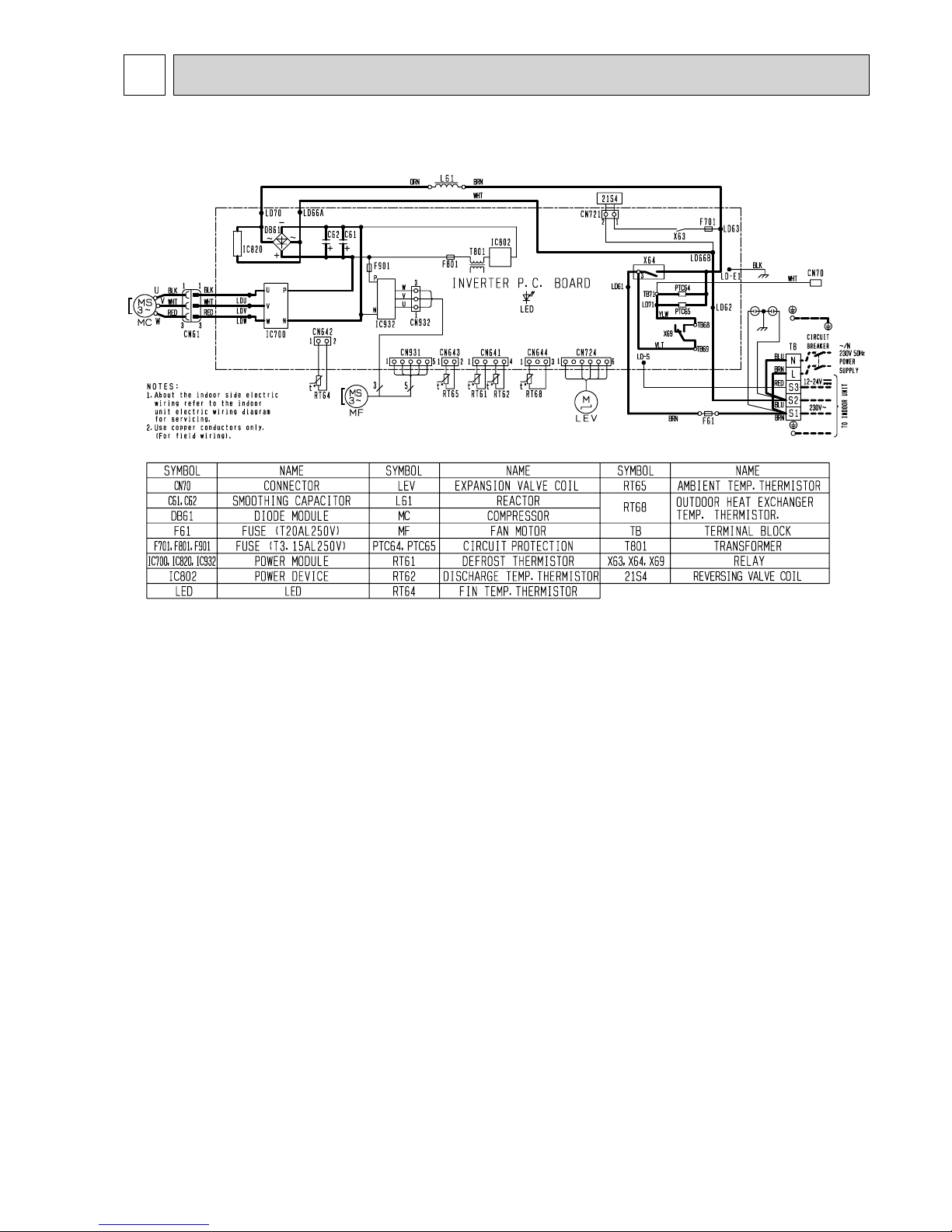
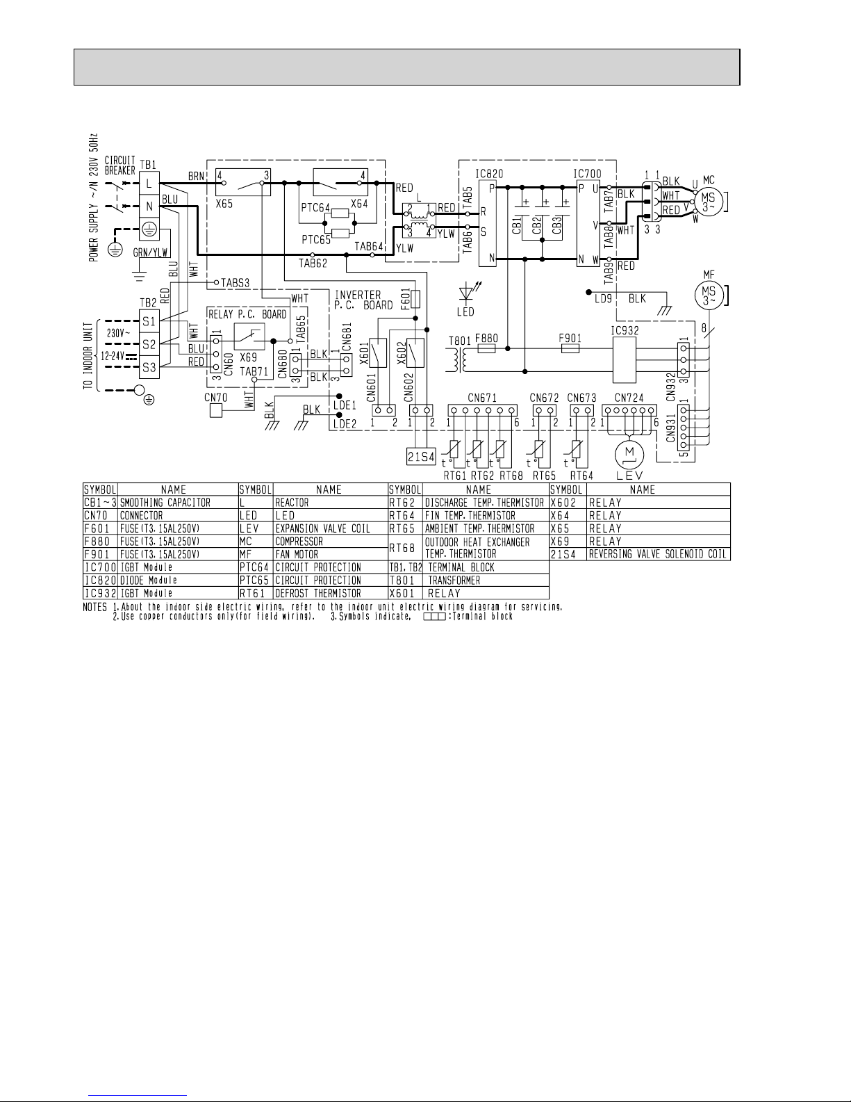
WIRING DIAGRAM
6
MUZ-FH25VE
MUZ-FH35VE
OBH624A
10
MUZ-FH50VE
OBH624A
11
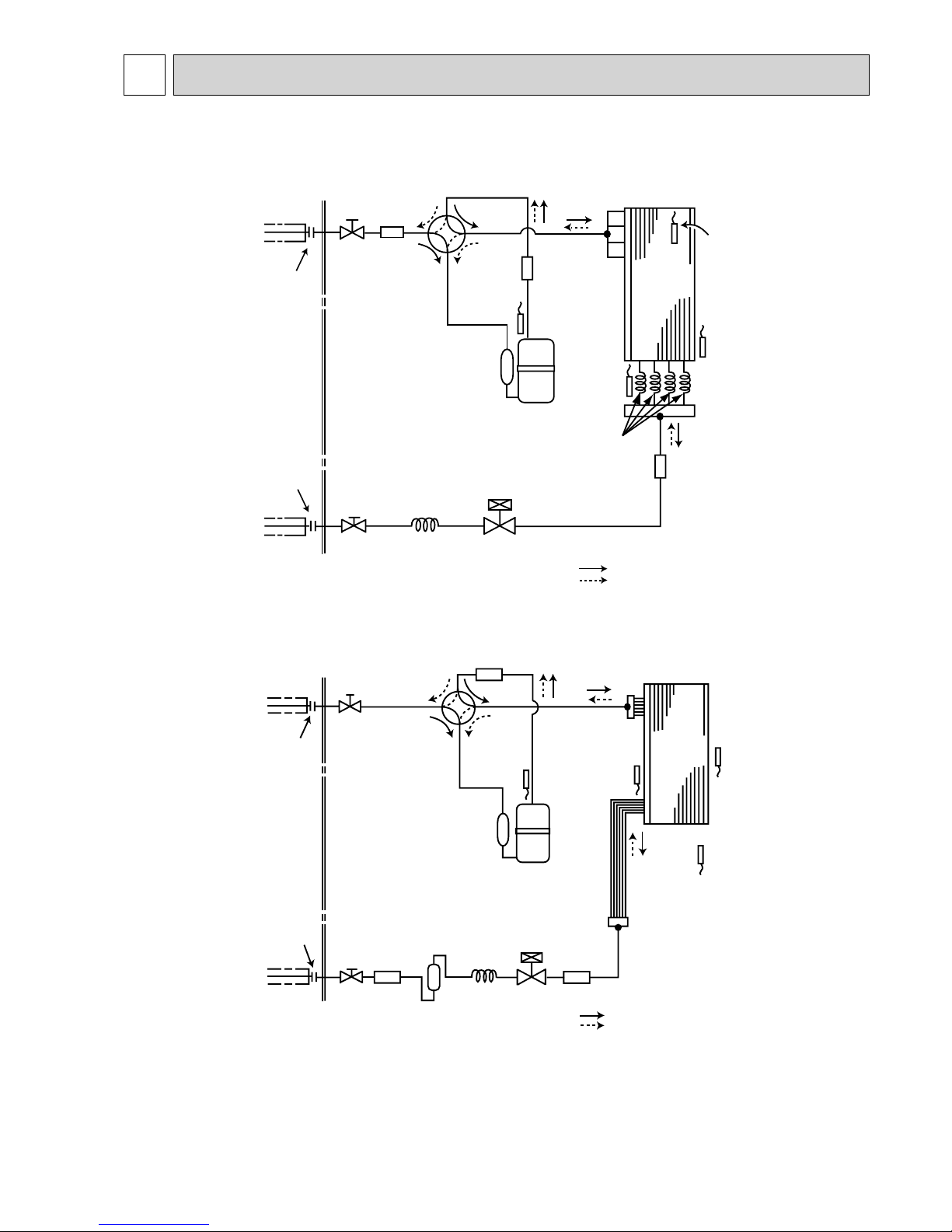
Unit: mm
MUZ-FH25VE
MUZ-FH35VE
Outdoor
heat
exchanger
Flared connection
Defrost
thermistor
RT61
Discharge
temperature
thermistor
RT62
Flared connection
Stop valve
(with strainar)
Stop valve
Refrigerant flow in cooling
Compressor
4-way valve
Refrigerant flow in heating
Refrigerant pipe ø9.52
(with heat insulator)
Refrigerant pipe ø6.35
(with heat insulator)
R.V. coil
heating ON
cooling OFF
Strainer
#100
LEV
Ambient
temperature
thermistor
RT65
Muffler
Capillary tube
ø4.0×ø2.4×240
Outdoor heat
exchanger
temperature
thermistor
RT68
Capillary tube
ø3.0×ø2.0×210
Muffler
REFRIGERANT SYSTEM DIAGRAM
7
MUZ-FH50VE
Outdoor
heat
exchanger
Flared connection
Defrost
thermistor
RT61
Discharge
temperature
thermistor
RT62
Flared connection
Stop valve
Stop valve
Capillary tube
ø
4.0
×
ø
2.4×100
Refrigerant flow in cooling
Compressor
4-way valve
Refrigerant flow in heating
Refrigerant pipe
ø
12.7
(with heat insulator)
Refrigerant pipe ø6.35
(with heat insulator)
LEV
Muffler
R.V. coil
heating ON
cooling OFF
Muffler
#100
Strainer
#100
Outdoor heat
exchanger
temperature
thermistor
RT68
Ambient
temperature
thermistor
RT65
Strainer
#100
OBH624A
12
Max. Length
A
Max. Height
difference
B
Indoor
unit
Outdoor unit
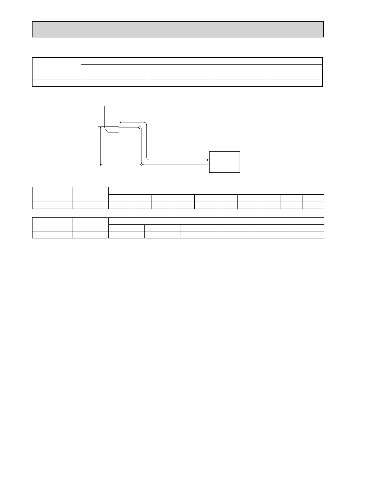
MAX. REFRIGERANT PIPING LENGTH and MAX. HEIGHT DIFFERENCE
Model
Refrigerant piping: m Piping size O.D: mm
Max. Length A Max. Height difference B Gas Liquid
MUZ-FH25/35 20 12 9.52 6.35
MUZ-FH50 30 15 12.7 6.35
ADDITIONAL REFRIGERANT CHARGE (R410A: g)
Model
Outdoor unit
precharged
Refrigerant piping length (one way)
7 m 8 m 9 m 10 m 11 m 12 m 13 m 14 m 15 m 20 m
MUZ-FH25/35 1,150
0 30 60 90 120 150 180 210 240 390
Calculation: X g = 30 g/m × (Refrigerant piping length (m) - 7)
Model
Outdoor unit
precharged
Refrigerant piping length (one way)
7 m 10 m 15 m 20 m 25 m 30 m
MUZ-FH50 1,550 0 60 160 260 360 460
Calculation: X g = 20 g/m × (Refrigerant piping length (m) – 7)
OBH624A
13
PERFORMANCE CURVES8
The standard specifications apply only to the operation of the air conditioner under normal conditions. Since operating conditions vary according to the areas where these units are installed, the following information has been provided to clarify the
operating characteristics of the air conditioner under the conditions indicated by the performance curve.
(1) GUARANTEED VOLTAGE
198 ~ 264 V, 50 Hz
(2) AIR FLOW
Air flow should be set at MAX.
(3) MAIN READINGS
(1) Indoor intake air wet-bulb temperature: °C [WB]
}
Cooling
(2) Indoor outlet air wet-bulb temperature: °C [WB]
(3) Outdoor intake air dry-bulb temperature: °C [DB]
(4) Total input: W
(5) Indoor intake air dry-bulb temperature: °C [DB]
}
Heating(6) Outdoor intake air wet-bulb temperature: °C [WB]
(7) Total input: W
Indoor air wet and dry bulb temperature difference on the left side of the following chart shows the difference between the
indoor intake air wet and dry bulb temperature and the indoor outlet air wet and dry bulb temperature for your reference at
service.
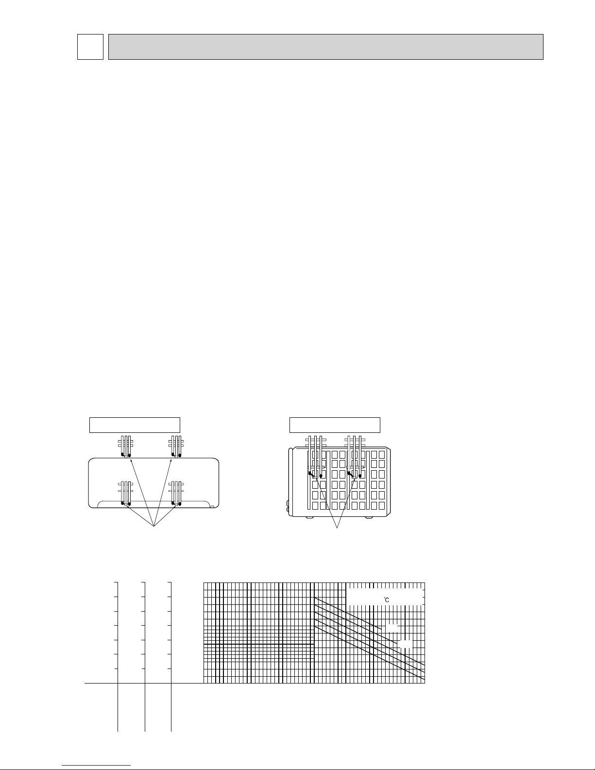
How to measure the indoor air wet and dry bulb temperature difference
1. Attach at least 2 sets of wet and dry bulb thermometers to the indoor air intake as shown in the figure, and at least 2 sets
of wet and dry bulb thermometers to the indoor air outlet. The thermometers must be attached to the position where air
speed is high.
2. Attach at least 2 sets of wet and dry bulb thermometers to the outdoor air intake.
Cover the thermometers to prevent direct rays of the sun.
3. Check that the air filter is cleaned.
4. Open windows and doors of room.
5. Press the EMERGENCY OPERATION switch once (twice) to start the EMERGENCY COOL (HEAT) MODE.
6. When system stabilizes after more than 15 minutes, measure temperature and take an average temperature.
7. 10 minutes later, measure temperature again and check that the temperature does not change.
MUZ-FH25VE
MUZ-FH35VE
MUZ-FH50VE
INDOOR UNIT
OUTDOOR UNIT
Wet and dry bulb
thermometers
FRONT VIEW
Wet and dry bulb
thermometers
BACK VIEW
Cooling capacity (
at Rated frequency)
0.9
1.0
1.1
1.2
1.3
1.4
1.5
-10-5 0 5 1015202530354045
Outdoor intake air Dry-bulb temperature(°C)
Capacity correction factors
26
24
20
18
22
Indoor intake air Wet-bulb
temperature( )
MUZ-FH35VE
MUZ-FH25VE
Indoor air Wet-bulb temperature
difference (°C)
6.4
5.9
5.5
5.0
4.6
4.1
3.7
9.5
8.7
8.0
7.3
6.6
5.9
5.3
MUZ-FH50VE
13.6
12.5
11.4
10.3
9.3
8.3
7.3
8-1. CAPACITY AND INPUT CURVES
OBH624A

14
NOTE: The above broken lines are for the heating operation without any frost and defrost operation.
0.8
0.9
1.0
1.1
1.2
1.3
-10-5 0 5 1015202530354045
Outdoor intake air Dry-bulb temperature (°C)
Input correction factors
26
24
22
20
18
Indoor intake air Wet-bulb
temperature( )
Indoor air Wet-bulb temperature
difference (°C)
5.5
5.0
4.6
4.1
3.7
3.2
8.0
7.3
6.6
5.9
5.3
4.6
MUZ-FH35VE
11.4
10.3
9.3
8.3
7.3
6.4
MUZ-FH50VE
MUZ-FH25VE
Total input (Cooling :
at Rated frequency
)
Indoor air Dry-bulb temperature
difference (°C)
15.9
14.6
13.4
12.2
11.0
9.8
8.5
7.3
6.1
4.9
MUZ-FH25VE
19.8
18.3
16.8
15.2
13.7
12.2
10.7
9.1
7.6
6.1
MUZ-FH35VE
26.9
24.8
22.7
20.7
18.6
16.5
14.5
12.4
10.3
8.3
MUZ-FH50VE
Outdoor intake air Wet-bulb temperature (°C)
-15 -10 -5 0 5 10 15
0.4
0.5
0.6
0.7
0.8
0.9
1.0
1.1
1.2
1.3
Heating capacity (
at Rated frequency)
Capacity correction factor
15
20
26
Indoor intake air Dry-bulb temperature ( )
Indoor air Dry-bulb temperature
difference (°C)
15.9
14.6
13.4
12.2
11.0
9.8
8.5
7.3
6.1
4.9
MUZ-FH25VE
19.8
18.3
16.8
15.2
13.7
12.2
10.7
9.1
7.6
6.1
MUZ-FH35VE
26.9
24.8
22.7
20.7
18.6
16.5
14.5
12.4
10.3
8.3
MUZ-FH50VE
Outdoor intake air Wet-bulb temperature (°C)
-15 -10 -5 0 5 10 15
0.4
0.5
0.6
0.7
0.8
0.9
1.0
1.1
1.2
1.3
Total input (Heating :
at Rated frequency
)
Input correction factor
15
20
26
Indoor intake air Dry-bulb temperature ( )
OBH624A
15
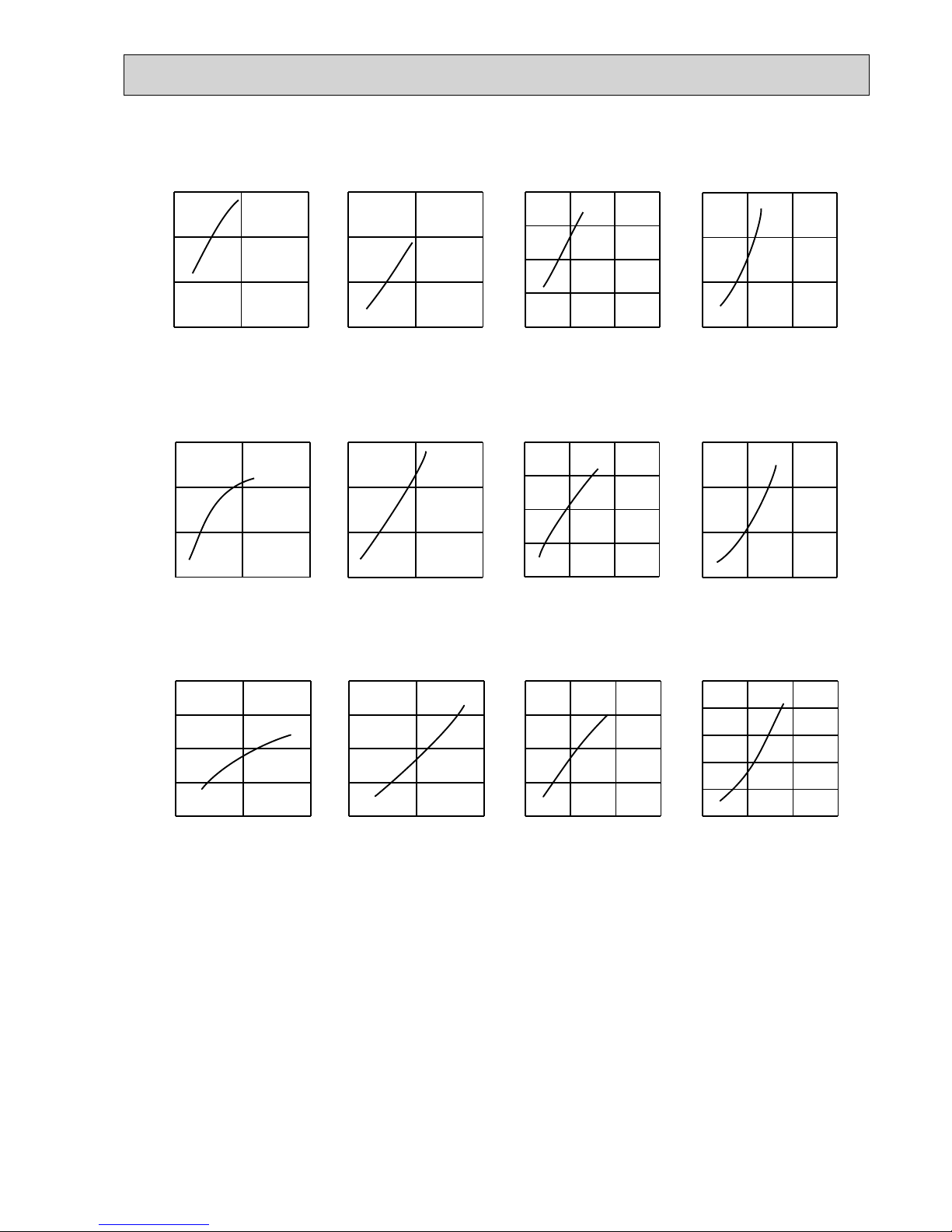
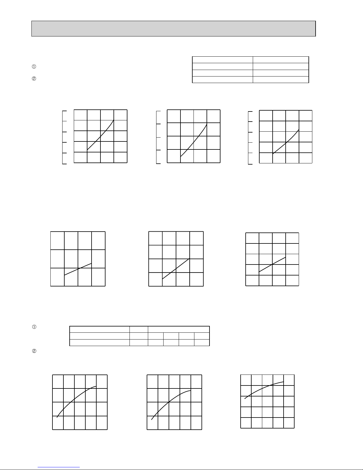
8-2. CAPACITY AND INPUT CORRECTION BY OPERATIONAL FREQUENCY OF COMPRESSOR
0 50 100
0.5
1.0
1.5
0 50 100
0.5
1.0
1.5
0 50 100
0.5
1.0
1.5
0 50 100
1
2
3
050100
150
0.5
1.0
1.5
2.0
0 50 100
150
1
2
3
0 50 100
150
0.5
1.0
1.5
2.0
0 50 100
150
1
2
3
MUZ-FH25VE
MUZ-FH35VE
Correction of Cooling capacity
The operational frequency
of compressor (Hz)
Capacity correction factors
Correction of Cooling input
The operationalfrequency
of compressor(Hz)
Input correction factors
Correction of Heating capacity
The operationalfrequency
of compressor (Hz)
Capacity correction factors
Correction of Heating input
The operational frequency
of compressor (Hz)
Input correction factors
Correction of Cooling capacity
The operational frequency
of compressor (Hz)
Capacity correction factors
Correction of Cooling input
The operational frequency
of compressor (Hz)
Input correction factors
Correction of Heatingcapacity
The operational frequency
of compressor (Hz)
Capacity correction factors
Correction of Heatinginput
The operational frequency
of compressor (Hz)
Input correction factors
Correction of Cooling capacity
Capacity correction factors
Correction of Cooling input
Input correction factors
Correction of Heating capacity
Capacity correction factors
MUZ-FH50VE
Correction of Heating input
Capacity correction factors
The operational frequency
of compressor (Hz)
The operational frequency
of compressor (Hz)
The operational frequency
of compressor (Hz)
The operational frequency
of compressor (Hz)
0 50 100
0.5
1.0
1.5
2.0
0 50 100
0.5
1.0
1.5
2.0
0 50 100 150
0.5
1.0
1.5
2.0
0 50 100 150
0.5
1.0
1.5
2.0
2.5
8-3. HOW TO OPERATE FIXED-FREQUENCY OPERATION
<Test run operation>
1. Press EMERGENCY OPERATION switch to start COOL or HEAT mode (COOL: Press once, HEAT: Press twice).
2. Test run operation starts and continues to operate for 30 minutes.
3. Compressor operates at rated frequency in COOL mode or 58 Hz in HEAT mode.
4. Indoor fan operates at High speed.
5.
After 30 minutes, test run operation finishes and EMERGENCY OPERATION starts (operation frequency of compressor varies).
6. To cancel test run operation (EMERGENCY OPERATION), press EMERGENCY OPERATION switch or any button on
remote controller.
OBH624A
16
15 20 25 30 35
0.4
0.5
0.6
0.7
0.8
0.9
15 20 25 30 35
0.4
0.5
0.6
0.7
0.8
Ambient temperature(°C)
Ambient humidity(%)
15 20 25 30 35
0.3
0.4
0.5
0.6
0.7
0.8
(kgf/cm2[Gauge])(MPa[Gauge])
6
5
4
7
8
9
(kgf/cm2[Gauge])(MPa [Gauge])
3
5
4
6
7
50 60 70
Ambient temperature(°C)
Ambient humidity(%)
50 60 70
Ambient temperature(°C)
Ambient humidity(%)
Outdoor low pressure
MUZ-FH25VE MUZ-FH35VE
MUZ-FH50VE
(kgf/cm2[Gauge])(MPa[Gauge])
50 60 70
3
5
4
6
7
8
COOL operation
Both indoor and outdoor unit are under the same temperature/
humidity condition.
Operation: TEST RUN OPERATION (Refer to 8-3.)
8-4. OUTDOOR LOW PRESSURE AND OUTDOOR UNIT CURRENT
Dry-bulb temperature (°C) Relative humidity (%)
20 50
25 60
30 70
NOTE:
The unit of pressure has been changed to MPa on the international system of units (SI unit system)
The conversion factor is: 1 (MPa [Gauge]) = 10.2 (kgf/cm2 [Gauge])
15 20502560307035
1.5
2.0
2.5
3.0
15 20502560307035
2.5
3.0
3.5
4.0
4.5
Ambient temperature (°C)
Ambi
ent humidity(%)
Outdoor current (A)
Ambient temperature (°C)
Ambient humidity(%)
Outdoor current (A)
MUZ-FH35VEMUZ-FH25VE
Outdoor unit current
15 20502560307035
3
4
5
6
7
8
MUZ-FH50VE
Ambient temperature (°C)
Ambient humidity(%)
Outdoor current (A)
0510
15 20 25
4.0
4.5
5.0
5.5
6.0
0510
15 20 25
4.0
4.5
5.0
5.5
6.0
0 5 10 15 20 25
3
4
5
6
7
8
Ambient temperature (°C)
Outdoor current (A)
Ambient temperature (°C)
Outdoor current (A)
MUZ-FH35VEMUZ-FH25VE
Outdoor unit current
MUZ-FH50VE
Ambient temperature (°C)
Outdoor current (A)
Condition:
Operation: Test run operation (Refer to 8-3.)
HEAT operation
Indoor Outdoor
Dry bulb temperature (°C) 20.0 2 7 15 20.0
Wet bulb temperature (°C) 14.5 1 6 12 14.5
OBH624A

17
PERFORMANCE DATA COOL operation at Rated frequency
MUZ-FH25VE
CAPACITY: 2.5 kW SHF: 0.95 INPUT: 485 W
INDOOR
DB (°C)
INDOOR
WB (°C)
OUTDOOR DB (°C)
21 25 27 30
Q SHC SHF INPUT Q SHC SHF INPUT Q SHC SHF INPUT Q SHC SHF INPUT
21 18 2.94 2.26 0.77 388 2.81 2.17 0.77 407 2.70 2.08 0.77 427 2.60 2.00 0.77 446
21 20 3.06 1.99 0.65 407 2.94 1.91 0.65 432 2.85 1.85 0.65 441 2.75 1.79 0.65 461
22 18 2.94 2.38 0.81 388 2.81 2.28 0.81 407 2.70 2.19 0.81 427 2.60 2.11 0.81 446
22 20 3.06 2.11 0.69 407 2.94 2.03 0.69 432 2.85 1.97 0.69 441 2.75 1.90 0.69 461
22 22 3.19 1.82 0.57 422 3.08 1.75 0.57 449 3.00 1.71 0.57 461 2.88 1.64 0.57 480
23 18 2.94 2.50 0.85 388 2.81 2.39 0.85 407 2.70 2.30 0.85 427 2.60 2.21 0.85 446
23 20 3.06 2.24 0.73 407 2.94 2.14 0.73 432 2.85 2.08 0.73 441 2.75 2.01 0.73 461
23 22 3.19 1.94 0.61 422 3.08 1.88 0.61 449 3.00 1.83 0.61 461 2.88 1.75 0.61 480
24 18 2.94 2.61 0.89 388 2.81 2.50 0.89 407 2.70 2.40 0.89 427 2.60 2.31 0.89 446
24 20 3.06 2.36 0.77 407 2.94 2.26 0.77 432 2.85 2.19 0.77 441 2.75 2.12 0.77 461
24 22 3.19 2.07 0.65 422 3.08 2.00 0.65 449 3.00 1.95 0.65 461 2.88 1.87 0.65 480
24 24 3.35 1.78 0.53 441 3.23 1.71 0.53 466 3.15 1.67 0.53 480 3.05 1.62 0.53 504
25 18 2.94 2.73 0.93 388 2.81 2.62 0.93 407 2.70 2.51 0.93 427 2.60 2.42 0.93 446
25 20 3.06 2.48 0.81 407 2.94 2.38 0.81 432 2.85 2.31 0.81 441 2.75 2.23 0.81 461
25 22 3.19 2.20 0.69 422 3.08 2.12 0.69 449 3.00 2.07 0.69 461 2.88 1.98 0.69 480
25 24 3.35 1.91 0.57 441 3.23 1.84 0.57 466 3.15 1.80 0.57 480 3.05 1.74 0.57 504
26 18 2.94 2.85 0.97 388 2.81 2.73 0.97 407 2.70 2.62 0.97 427 2.60 2.52 0.97 446
26 20 3.06 2.60 0.85 407 2.94 2.50 0.85 432 2.85 2.42 0.85 441 2.75 2.34 0.85 461
26 22 3.19 2.33 0.73 422 3.08 2.24 0.73 449 3.00 2.19 0.73 461 2.88 2.10 0.73 480
26 24 3.35 2.04 0.61 441 3.23 1.97 0.61 466 3.15 1.92 0.61 480 3.05 1.86 0.61 504
26 26 3.45 1.69 0.49 466 3.35 1.64 0.49 490 3.30 1.62 0.49 504 3.20 1.57 0.49 519
27 18 2.94 2.94 1.00 388 2.81 2.81 1.00 407 2.70 2.70 1.00 427 2.60 2.60 1.00 446
27 20 3.06 2.73 0.89 407 2.94 2.61 0.89 432 2.85 2.54 0.89 441 2.75 2.45 0.89 461
27 22 3.19 2.45 0.77 422 3.08 2.37 0.77 449 3.00 2.31 0.77 461 2.88 2.21 0.77 480
27 24 3.35 2.18 0.65 441 3.23 2.10 0.65 466 3.15 2.05 0.65 480 3.05 1.98 0.65 504
27 26 3.45 1.83 0.53 466 3.35 1.78 0.53 490 3.30 1.75 0.53 504 3.20 1.70 0.53 519
28 18 2.94 2.94 1.00 388 2.81 2.81 1.00 407 2.70 2.70 1.00 427 2.60 2.60 1.00 446
28 20 3.06 2.85 0.93 407 2.94 2.73 0.93 432 2.85 2.65 0.93 441 2.75 2.56 0.93 461
28 22 3.19 2.58 0.81 422 3.08 2.49 0.81 449 3.00 2.43 0.81 461 2.88 2.33 0.81 480
28 24 3.35 2.31 0.69 441 3.23 2.23 0.69 466 3.15 2.17 0.69 480 3.05 2.10 0.69 504
28 26 3.45 1.97 0.57 466 3.35 1.91 0.57 490 3.30 1.88 0.57 504 3.20 1.82 0.57 519
29 18 2.94 2.94 1.00 388 2.81 2.81 1.00 407 2.70 2.70 1.00 427 2.60 2.60 1.00 446
29 20 3.06 2.97 0.97 407 2.94 2.85 0.97 432 2.85 2.76 0.97 441 2.75 2.67 0.97 461
29 22 3.19 2.71 0.85 422 3.08 2.61 0.85 449 3.00 2.55 0.85 461 2.88 2.44 0.85 480
29 24 3.35 2.45 0.73 441 3.23 2.35 0.73 466 3.15 2.30 0.73 480 3.05 2.23 0.73 504
29 26 3.45 2.10 0.61 466 3.35 2.04 0.61 490 3.30 2.01 0.61 504 3.20 1.95 0.61 519
30 18 2.94 2.94 1.00 388 2.81 2.81 1.00 407 2.70 2.70 1.00 427 2.60 2.60 1.00 446
30 20 3.06 3.06 1.00 407 2.94 2.94 1.00 432 2.85 2.85 1.00 441 2.75 2.75 1.00 461
30 22 3.19 2.84 0.89 422 3.08 2.74 0.89 449 3.00 2.67 0.89 461 2.88 2.56 0.89 480
30 24 3.35 2.58 0.77 441 3.23 2.48 0.77 466 3.15 2.43 0.77 480 3.05 2.35 0.77 504
30 26 3.45 2.24 0.65 466 3.35 2.18 0.65 490 3.30 2.15 0.65 504 3.20 2.08 0.65 519
31 18 2.94 2.94 1.00 388 2.81 2.81 1.00 407 2.70 2.70 1.00 427 2.60 2.60 1.00 446
31 20 3.06 3.06 1.00 407 2.94 2.94 1.00 432 2.85 2.85 1.00 441 2.75 2.75 1.00 461
31 22 3.19 2.96 0.93 422 3.08 2.86 0.93 449 3.00 2.79 0.93 461 2.88 2.67 0.93 480
31 24 3.35 2.71 0.81 441 3.23 2.61 0.81 466 3.15 2.55 0.81 480 3.05 2.47 0.81 504
31 26 3.45 2.38 0.69 466 3.35 2.31 0.69 490 3.30 2.28 0.69 504 3.20 2.21 0.69 519
32 18 2.94 2.94 1.00 388 2.81 2.81 1.00 407 2.70 2.70 1.00 427 2.60 2.60 1.00 446
32 20 3.06 3.06 1.00 407 2.94 2.94 1.00 432 2.85 2.85 1.00 441 2.75 2.75 1.00 461
32 22 3.19 3.09 0.97 422 3.08 2.98 0.97 449 3.00 2.91 0.97 461 2.88 2.79 0.97 480
32 24 3.35 2.85 0.85 441 3.23 2.74 0.85 466 3.15 2.68 0.85 480 3.05 2.59 0.85 504
32 26 3.45 2.52 0.73 466 3.35 2.45 0.73 490 3.30 2.41 0.73 504 3.20 2.34 0.73 519
NOTE Q : Total capacity (kW) SHF : Sensible heat factor DB : Dry-bulb temperature
SHC : Sensible heat capacity (kW) INPUT : Total power input (W) WB : Wet-bulb temperature
OBH624A
 Loading...