

Mitsubishi MUZ-A09NA, MUZ-A12NA, MUZ-A15NA, MUZ-A17NA, MUZ-A24NA Service Manual
...
SPLIT-TYPE, HEAT PUMP AIR CONDITIONERS
OUTDOOR UNIT
HFC
utilized
R410A
SERVICE MANUAL
Wireless type
Models
No. OB451
MUZ-A09NA MUZ-A09NAMUZ-A12NA MUZ-A12NAMUZ-A15NA MUZ-A15NAMUZ-A17NA MUZ-A17NAMUZ-A24NA MUZ-A24NAMUY-A15NA
MUY-A17NA
MUY-A24NA
MUZ-A09NA MUY-A15NA
MUZ-A12NA MUY-A17NA
MUZ-A15NA
CONTENTS
1. TECHNICAL CHANGES ····································2
2. PART NAMES AND FUNCTIONS······················5
3. SPECIFICATION·················································6
4. OUTLINES AND DIMENSIONS·······················10
5. WIRING DIAGRAM···········································11
6. REFRIGERANT SYSTEM DIAGRAM··············15
7. DATA·································································17
8. ACTUA TOR CONTROL····································30
9. SERVICE FUNCTIONS ····································31
10. TROUBLESHOOTING ······································31
11. DISASSEMBLY INSTRUCTIONS·····················59
12. PARTS LIST······················································66
12-1. PARTS LIST ·············································66
12-2. RoHS PARTS LIST··································72
13. OPTIONAL PARTS ·························BACK PAGE
Indoor unit service manual
MSZ-A•NA Series (OB450)
U1
U1
U1
U1
U1
NOTE:
This service manual describes technical data of the outdoor units.
RoHS compliant products have <G> mark on the spec name plate.
For servicing of RoHS compliant products, refer to the PARTS
LIST (RoHS compliant).
TM
1
Refrigeration
oil
Refrigerant
New refrigerant
R410A
HFC-32: HFC-125 (50%:50%)
Pseudo-azeotropic refrigerant
Not included
A1/A1
72.6
-60.5
225.82
3.995
Non combustible
0
1730
From liquid phase in cylinder
Possible
Incompatible oil
Non
Non
Previous refrigerant
R22
R22 (100%)
Single refrigerant
Included
A1
86.5
-41.4
136.34
2.772
Non combustible
0.055
1700
Gas phase
Possible
Compatible oil
Light yellow
Non
Refrigerant
Composition (Ratio)
Refrigerant handling
Chlorine
Safety group (ASHRAE)
Molecular weight
Boiling point (°F)
Steam pressure [77°F](PSIG)
Saturated steam density [77°F](lb/ft
3
)
Combustibility
ODP w1
GWP w2
Refrigerant charge method
Additional charge on leakage
Kind
Color
Smell
w1:Ozone Destruction Parameter : based on CFC-11
w2 :Global Warmth Parameter : based on CO
2
TECHNICAL CHANGES
MUZ09UN ➔ MUZ-A09NA
MUZ12UN ➔ MUZ-A12NA
MUH15TN ➔ MUZ-A15NA
MUH17TN ➔ MUZ-A17NA
MUH24WN ➔ MUZ-A24NA
MU15TN ➔ MUY-A15NA
MU17TN ➔ MUY-A17NA
MU24WN ➔ MUY-A24NA
1. Outdoor unit model has been changed.
2. Control method between indoor and outdoor unit has been changed.
3. Refrigerant has been changed. (R22 ➔ R410A)
4. Fan motor has been changed. (AC ➔ DC)
5. Compressor has been changed. (AC ➔ DC)
INFORMATION FOR THE AIR CONDITIONER WITH R410A REFRIGERANT
• This room air conditioner adopts HFC refrigerant (R410A) which never destroys the ozone layer.
• Pay particular attention to the following points, though the basic installation procedure is same as that for R22 air
conditioners.
1 As R410A has working pressure approximate 1.6 times as high as that of R22, some special tools and piping parts/
materials are required. Refer to the table below.
2 Take sufficient care not to allow water and other contaminations to enter the R410Arefrigerant during storage and
installation, since it is more susceptible to contaminations than R22.
3 For refrigerant piping, use clean, pressure-proof parts/materials specifically designed for R410A. (Refer to 2. Refrigerant
piping.)
4 Composition change may occur in R410A since it is a mixed refrigerant. When charging, charge liquid refrigerant to prevent
composition change.
2
1.Tools dedicated for the air conditioner with R410A refrigerant
New Specification Current Specification
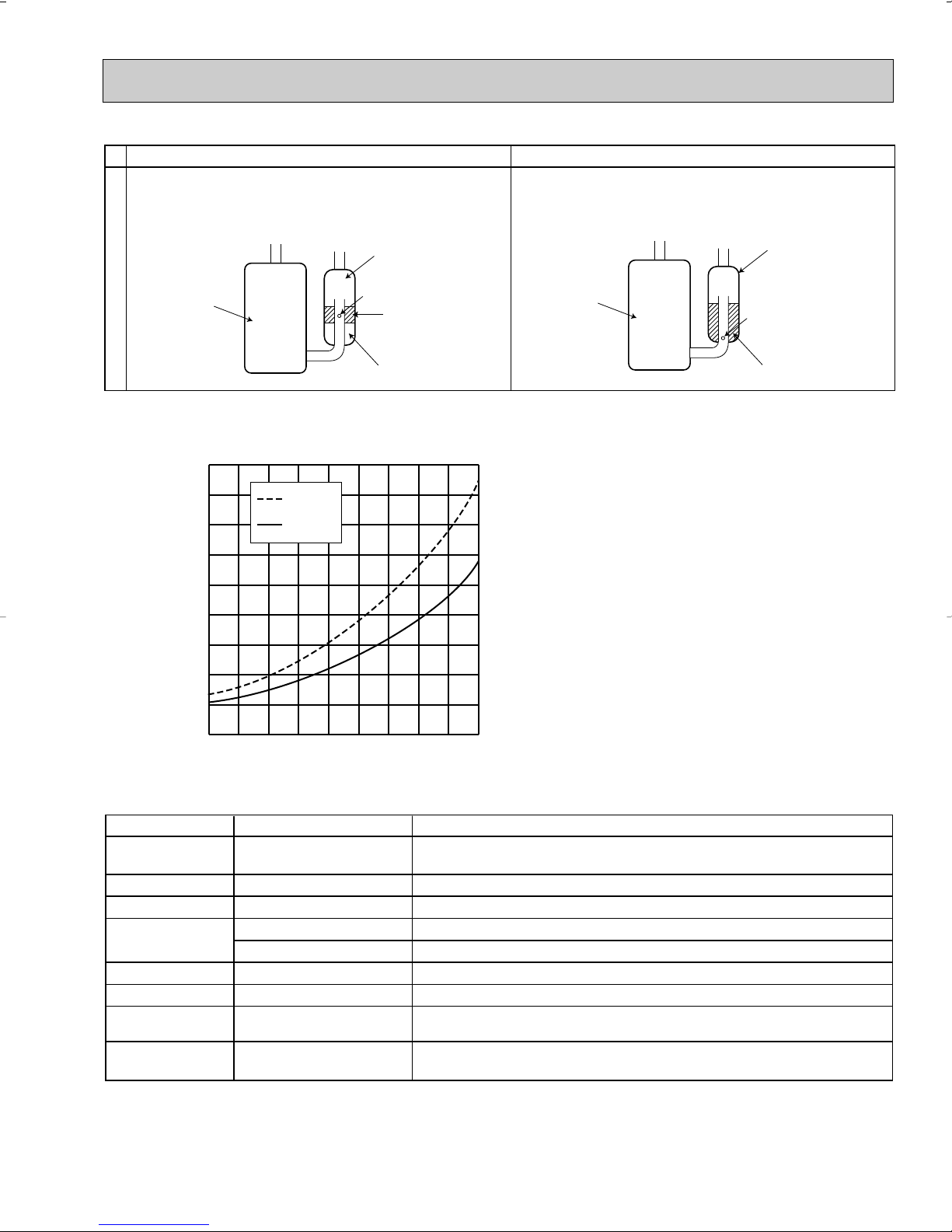
The incompatible refrigeration oil easily separates from
refrigerant and is in the upper layer inside the suction muffler.
Raising position of the oil back hole enables to back the
refrigeration oil of the upper layer to flow back to the
compressor.
Since refrigerant and refrigeration oil are compatible each,
refrigeration oil goes back to the compressor through the
lower position oil back hole.
Compressor
Suction muffler
Oil back hole
refrigeration oil
Refrigerant
Compressor
Suction muffler
Oil back hole
refrigeration oil /Refrigerant
Compressor
-22 -4 14 32 50 68
86
104 122 140
-73
0
73
145
218
290
363
435
508
580
(PSIG)
R410A
R22
Conversion chart of refrigerant temperature and pressure
Saturated liquid pressure
(°F)
The following tools are required for R410A refrigerant. Some R22 tools can be substituted for R410A tools.
R410A tools
Gauge manifold
Charge hose
Gas leak detector
Torque wrench
Can R22 tools be used?
No
No
No
Yes
No 1/2in. and 5/8in.
Flare tool
Flare gauge
Vacuum pump
adapter
Electronic scale for
refrigerant charging
No : Not Substitutable for R410A Yes : Substitutable for R410A
Yes
New
New
New
Description
R410A has high pressures beyond the measurement range of existing
gauges.
Hose material have been changed to improve the pressure resistance.
Dedicated for HFC refrigerant.
1/4in. and 3/8in.
Clamp bar hole has been enlarged to reinforce the spring strength in the tool.
Provided for flaring work (to be used with R22 flare tool).
Provided to prevent the back flow of oil. This adapter enables you to use
vacuum pumps.
It is difficult to measure R410A with a charging cylinder because the
refrigerant bubbles due to high pressure and high-speed vaporization
3
R410A
Pipe diameter
inch
1/4
3/8
1/2
5/8
17 (11/16)
22 (7/8)
26 (1-1/32)
29 (1-5/32)
Dimension of flare nut
R22
mm(in)
17 (11/16)
22 (7/8)
24 (15/16)
27 (1-1/16)
2.Refrigerant piping
Wall thickness (in)
Outside diameter(in)
1/4
3/8
1/2
5/8
0.0315
0.0315
0.0315
0.0394
Heat resisting foam plastic
Specific gravity 0.045 Thickness 0.315 in
Insulation material
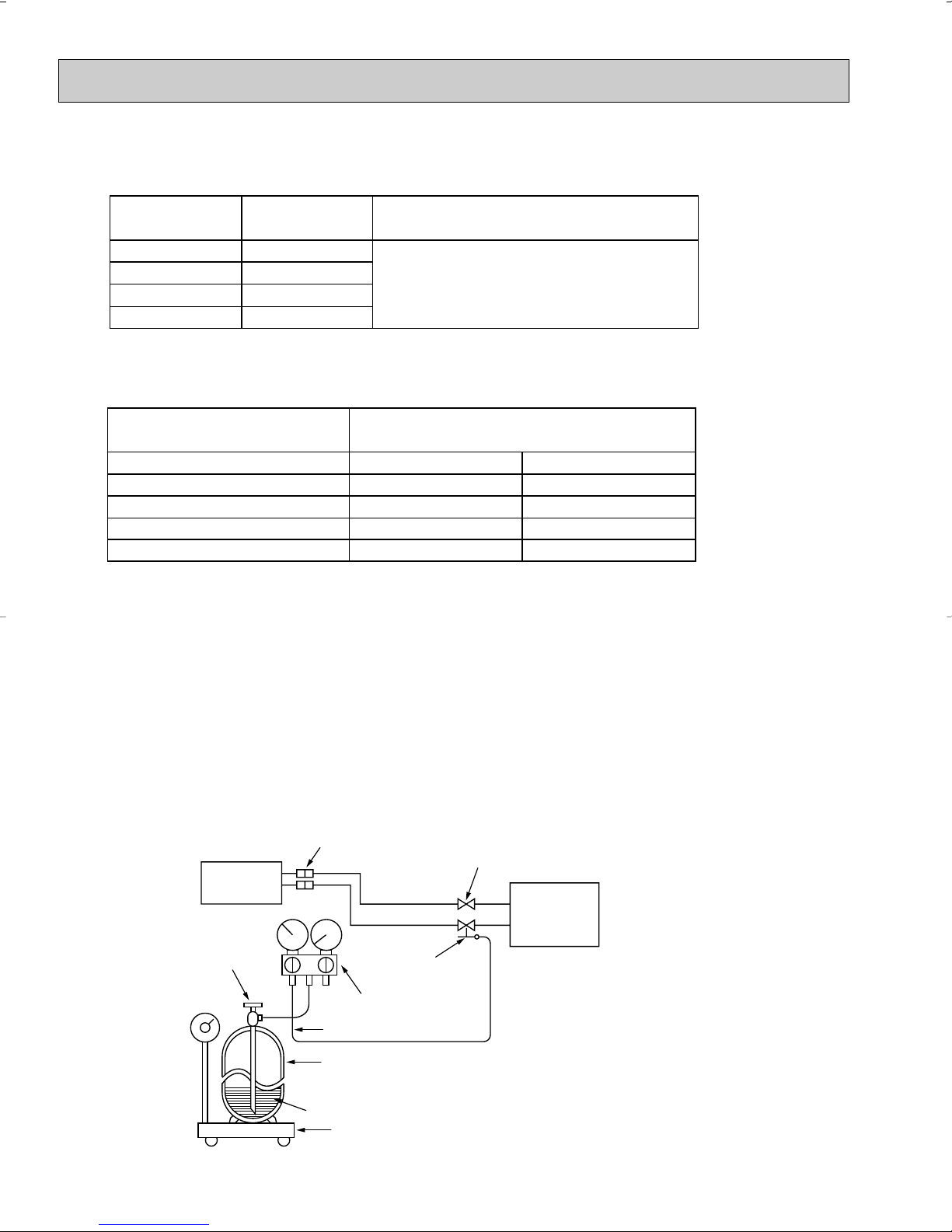
Electronic scale for refrigerant charging
Outdoor unit
Refrigerant gas
cylinder
operating valve
Refrigerant gas cylinder
for R410A with siphon
Refrigerant (liquid)
Service port
Gauge manifold
valve (for R410A)
Union
Liquid pipe
Gas pipe
Stop valve
Indoor unit
Charge hose (for R410A)
1 Specifications
Use the copper or copper-alloy seamless pipes for refrigerant that meet the following specifications.
2 Flaring work and flare nut
Flaring work for R410A pipe differs from that for R22 pipe.
For details of flaring work, refer to Installation manual “FLARING WORK”.
3.Refrigerant oil
Apply the special refrigeration oil (accessories: packed with indoor unit) to the flare and the union seat surfaces.
4.Air purge
• Do not discharge the refrigerant into the atmosphere.
Take care not to discharge refrigerant into the atmosphere during installation, reinstallation, or repairs to the refrigerant
circuit.
• Use the vacuum pump for air purging for the purpose of environmental protection.
5.Additional charge
For additional charging, charge the refrigerant from liquid phase of the gas cylinder.
If the refrigerant is charged from the gas phase, composition change may occur in the refrigerant inside the cylinder and the
outdoor unit. In this case, ability of the refrigeration cycle decreases or normal operation can be impossible. However,
charging the liquid refrigerant all at once may cause the compressor to be locked. Thus, charge the refrigerant slowly.
4
2
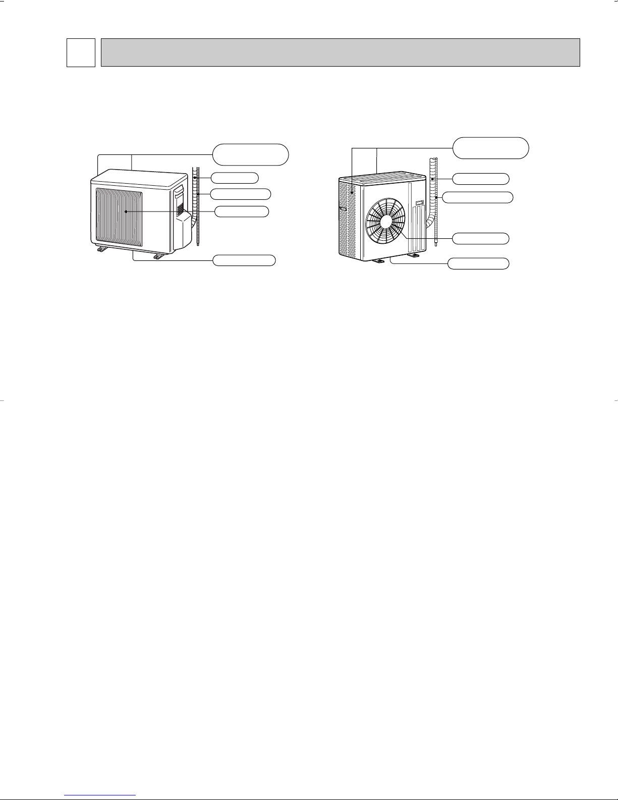
Air outlet
Drain outlet
Piping
Drain hose
Air inlet
(back and side)
Piping
Air outlet
Drain hose
Drain outlet
Air inlet
(back and side)
PART NAMES AND FUNCTIONS
MUZ-A09NA MUZ-A15NA MUY-A15NA
MUZ-A12NA MUZ-A17NA MUY-A17NA
MUZ-A24NA
MUY-A24NA
5
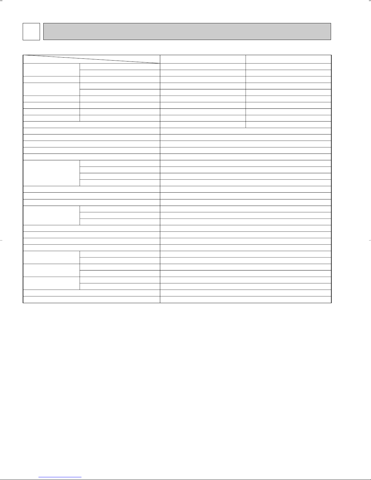
3
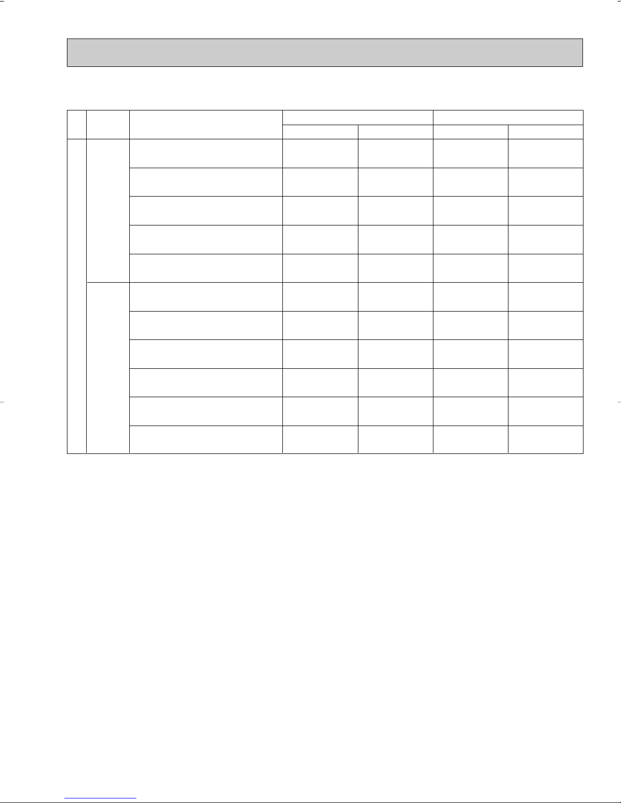
Item
Model
MSZ-A12NA
Capacity
Rated(Minimum~Maximum)
Capacity Rated
Power consumption
Rated(Minimum~Maximum)
Power consumption Rated
EER [SEER]
HSPF IV(V)
COP
OUTDOOR UNIT MODEL
External finish
Power supply
Max. fuse size (time delay)
Min. circuit ampacity
Fan motor
Compressor
Refrigerant control
Sound level
Defrost method
Dimensions
Weight
REMOTE CONTROLLER
Control voltage (by built-in transformer)
REFRIGERANT PIPING
Refrigerant pipe size
(Min. wall thickness)
Connection method
Between the indoor
& outdoor units
Refrigerant charge (R410A)
Refrigerating oil (Model)
Btu/h
Btu/h
Btu/h
W
W
W
V, phase, Hz
A
A
F.L.A
R.L.A
L.R.A
dB(A)
in.
in.
in.
Ib.
in.
in.
ft.
ft.
cc.
Munsell 3Y 7.8/1.1
208/230, 1, 60
15
12
0.52
KNB092FPAH
0.49
7.8
9.2
Liner expansion valve
48
Reverse cycle
31-1/2
11-1/4
21-5/8
82
Wireless type
12-24V DC
Not supplied
1/4 (0.0315)
3/8 (0.0315)
Flared
Flared
40
65
2lb.5oz.
320 (NE022)
9,000 (5,500~9,000)
10,900 (5,200~12,600)
7,700
690 (390~690)
860 (350~1,100)
880
13.0 [17.0]
8.2 (6.7)
3.71
12,000 (5,700~12,000)
13,600 (5,200~13,600)
8,300
1,170 (395~1,170)
1,160 (350~1,160)
930
10.3 [17.0]
8.2 (6.7)
3.44
MUZ-A09NA MUZ-A12NA
❈1 ❈3
❈1
❈1
❈2
❈1
❈1
❈2
Cooling
Heating 47
Heating 17
Cooling
Heating 47
Heating 17
Cooling
Heating
Heating
MSZ-A09NA
Model
Winding resistance (at 68˚F) Ω
W
D
H
Liquid
Gas
Indoor
Outdoor
Height difference
Piping length
❈1
❈1
❈4
SPECIFICATION
NOTE : Test conditions are based on ARI 210/240.
❈1 : Rating conditions (cooling) — Indoor : 80˚FDB, 67˚FWB, Outdoor : 95˚FDB, (75˚FWB) Rated frequency: A09:50Hz A12:76Hz
❈2 : (heating) — Indoor : 70˚FDB, 60˚FWB, Outdoor : 17˚FDB, 15˚FWB Maximum frequency: A09:71Hz A12:76Hz
(heating) — Indoor : 70˚FDB, 60˚FWB, Outdoor : 47˚FDB, 43˚FWB Rated frequency: A09:61Hz A12:76Hz
6
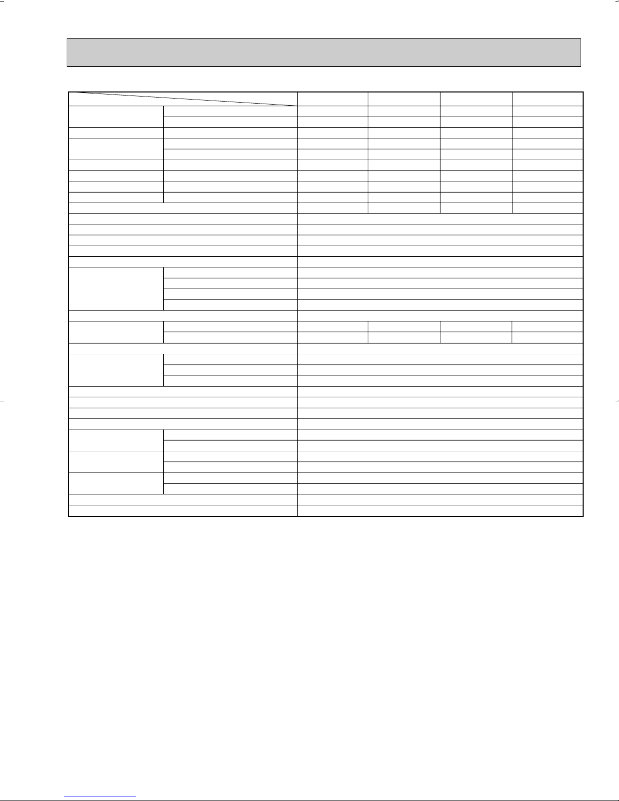
Item
Model
Capacity
Rated(Minimum~Maximum)
Capacity Rated
Power consumption
Rated(Minimum~Maximum)
Power consumption Rated
EER [SEER]
HSPF IV(V)
COP
OUTDOOR UNIT MODEL
External finish
Power supply
Max. fuse size (time delay)
Min. circuit ampacity
Fan motor
Compressor
Refrigerant control
Sound level dB(A)
Defrost method
Dimensions
Weight
REMOTE CONTROLLER
Control voltage (by built-in transformer)
REFRIGERANT PIPING
Refrigerant pipe size
(Min. wall thickness)
Connection method
Between the indoor
& outdoor units
Refrigerant charge (R410A)
Refrigerating oil (Model)
Btu/h
Btu/h
Btu/h
W
W
W
V, phase, Hz
A
A
F.L.A
R.L.A
L.R.A
in.
in.
in.
Ib.
in.
in.
ft.
ft.
cc.
16,200 (3,100~16,200)
–
–
2,070 (210~2,070)
–
–
7.8 [16.0]
–
–
16,200 (3,100~16,200)
20,100 (3,400~20,900)
13,000
2,070 (210~2,070)
2,150 (250~2,330)
1,740
7.8 [16.0]
8.2 (6.7)
2.74
15,000 (3,100~15,000)
18,000 (3,400~20,900)
13,000
1,690 (210~1,690)
1,790 (250~2,330)
1,740
8.9 [16.0]
8.2 (6.7)
2.95
50
51
50
—
52
53
52
—
15,000 (3,100~15,000)
–
–
1,690 (210~1,690)
–
–
8.9 [16.0]
–
–
❈1 ❈3
❈1
❈1
❈2
❈1
❈1
❈2
Cooling
Heating 47
Heating 17
Cooling
Heating 47
Heating 17
Cooling
Heating
Heating
Model
Winding resistance (at 68°F) "
Cooling
Heating
W
D
H
Liquid
Gas
Indoor
Outdoor
Height difference
Piping length
MSZ-A15NA MSY-A15NA MSZ-A17NA MSY-A17NA
MUZ-A15NA MUY-A15NA MUZ-A17NA MUY-A17NA
❈1
❈1 ❈1
❈4
Munsell 3Y 7.8/1.1
208/230, 1, 60
15
14
0.52
SNB130FPDH
0.45
10.1
12.0
Liner expansion valve
Reverse cycle
31-1/2
11-1/4
21-5/8
88
Wireless type
12-24V DC
Not supplied
1/4 (0.0315)
1/2 (0.0315)
Flared
Flared
40
65
2lb.7oz.
450 (NE022)
NOTE : Test conditions are based on ARI 210/240.
❈1 : Rating conditions (cooling) — Indoor : 80˚FDB, 67˚FWB, Outdoor : 95˚FDB, (75˚FWB) Rated frequency: A15:77Hz A17:89Hz
❈2 : (heating) — Indoor : 70˚FDB, 60˚FWB, Outdoor : 17˚FDB, 15˚FWB Maximum frequency: A15:93Hz A17:93Hz
(heating) — Indoor : 70˚FDB, 60˚FWB, Outdoor : 47˚FDB, 43˚FWB Rated frequency: A15:78Hz A17:88Hz
7
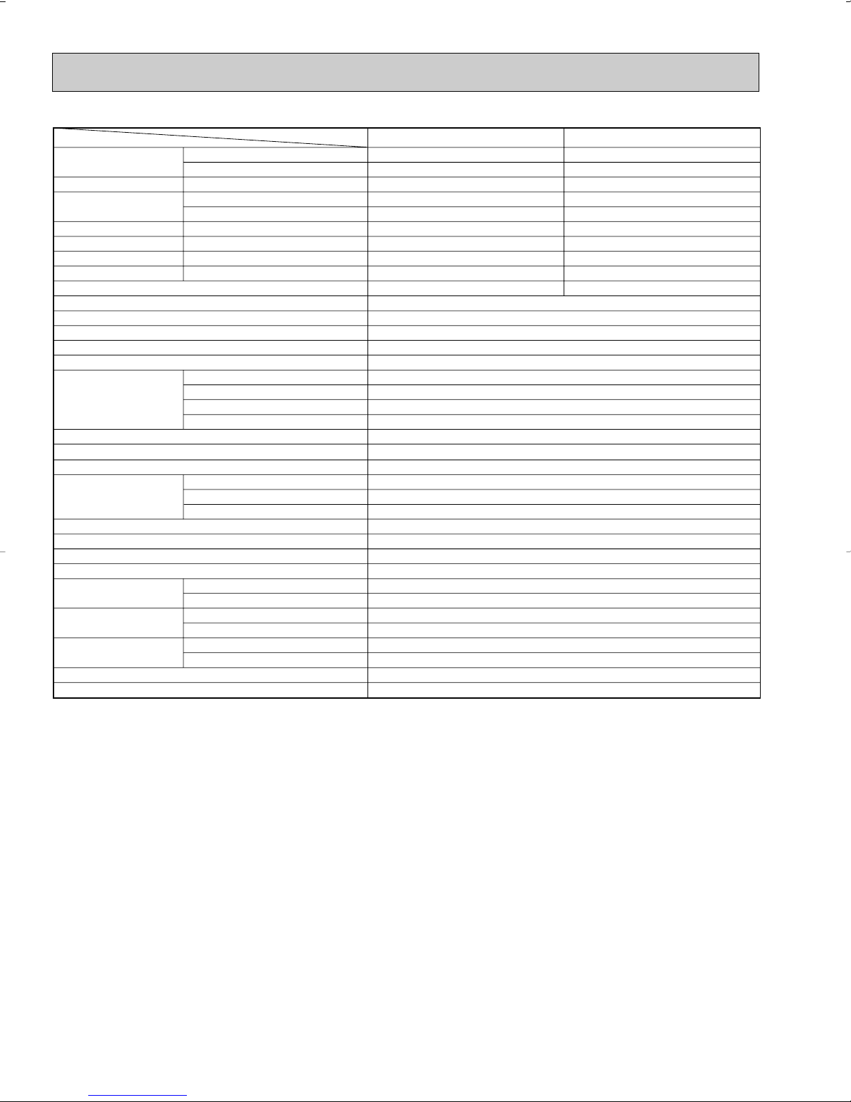
Item
Model
MSY-A24NA
Capacity
Rated(Minimum~Maximum)
Capacity Rated
Power consumption
Rated(Minimum~Maximum)
Power consumption Rated
EER [SEER]
HSPF IV(V)
COP
OUTDOOR UNIT MODEL
External finish
Power supply
Max. fuse size (time delay)
Min. circuit ampacity
Fan motor
Compressor
Refrigerant control
Sound level
Defrost method
Dimensions
Weight
REMOTE CONTROLLER
Control voltage (by built-in transformer)
REFRIGERANT PIPING
Refrigerant pipe size
(Min. wall thickness)
Connection method
Between the indoor
& outdoor units
Refrigerant charge (R410A)
Refrigerating oil (Model)
Btu/h
Btu/h
Btu/h
W
W
W
V, phase, Hz
A
A
F.L.A
R.L.A
L.R.A
dB(A)
in.
in.
in.
Ib.
in.
in.
ft.
ft.
cc.
Munsell 3Y 7.8 1.1
208/230, 1, 60
20
17
0.93
SNB130FPDH
0.45
10.1
16.0
Liner expansion valve
55
Reverse cycle
33-1/16
13
33-7/16
128
Wireless type
12-24VDC
Not supplied
1/4 (0.0315)
5/8 (0.0394)
Flared
Flared
50
100
4lb.
450 (NE022)
22,000 (4,400~22,000)
23,200 (3,600~24,400)
15,200
2,880 (290~2,880)
2,350 (260~2,570)
1,960
7.6 [16.0]
8.2 (6.7)
2.89
22,000 (4,400~22,000)
—
—
2,880 (290~2,880)
—
—
7.6 [16.0]
—
—
❈1 ❈3
❈1
❈1
❈2
❈1
❈1
❈2
Cooling
Heating 47
Heating 17
Cooling
Heating 47
Heating 17
Cooling
Heating
Heating
MSZ-A24NA
MUZ-A24NA MUY-A24NA
Model
Winding resistance (at 68˚F) Ω
W
D
H
Liquid
Gas
Indoor
Outdoor
Height difference
Piping length
❈1
❈1
❈4
NOTE : Test conditions are based on ARI 210/240.
❈1 : Rating conditions (cooling) — Indoor : 80˚FDB, 67˚FWB, Outdoor : 95˚FDB, (75˚FWB) Rated frequency: 110Hz
❈2 : (heating) — Indoor : 70˚FDB, 60˚FWB, Outdoor : 17˚FDB, 15˚FWB Maximum frequency: 108Hz
(heating) — Indoor : 70˚FDB, 60˚FWB, Outdoor : 47˚FDB, 43˚FWB Rated frequency: 101Hz
8
Test condition
SEER
(Cooling)
HSPF
(Heating)
ARI
Mode
"A" Cooling Steady State
at rated compressor Speed
"B-2" Cooling Steady State
at rated compressor Speed
"B-1" Cooling Steady State
at minimum compressor Speed
Low ambient Cooling Steady State
at minimum compressor Speed
Intermediate Cooling Steady State
At Intermediate compressor Speed
❈5
Standard Rating-Heating
at rated compressor Speed
Low temperature Heating
at rated compressor Speed
Max temperature Heating
at minimum compressor Speed
High temperature Heating
at minimum compressor Speed
Frost Accumulation
at rated compressor Speed
Test
Indoor air condition Outdoor air condition
Dry bulb
Wet bulb
Dry bulb
Wet bulb
80
80
80
80
80
70
70
70
70
70
70
67
67
67
67
67
60
60
60
60
60
60
Frost Accumulation
at Intermediate compressor Speed
❈5
95
82
82
67
87
47
17
62
47
35
35
(75)
(65)
(65)
(53.5)
(69)
43
15
56.5
43
33
33
❈5 : At Intermediate compressor Speed
=("Cooling rated compressor speed" - "minimum compressor speed") / 3 + "minimum compressor speed".
(Unit : [˚F])
❈3, ❈4
9
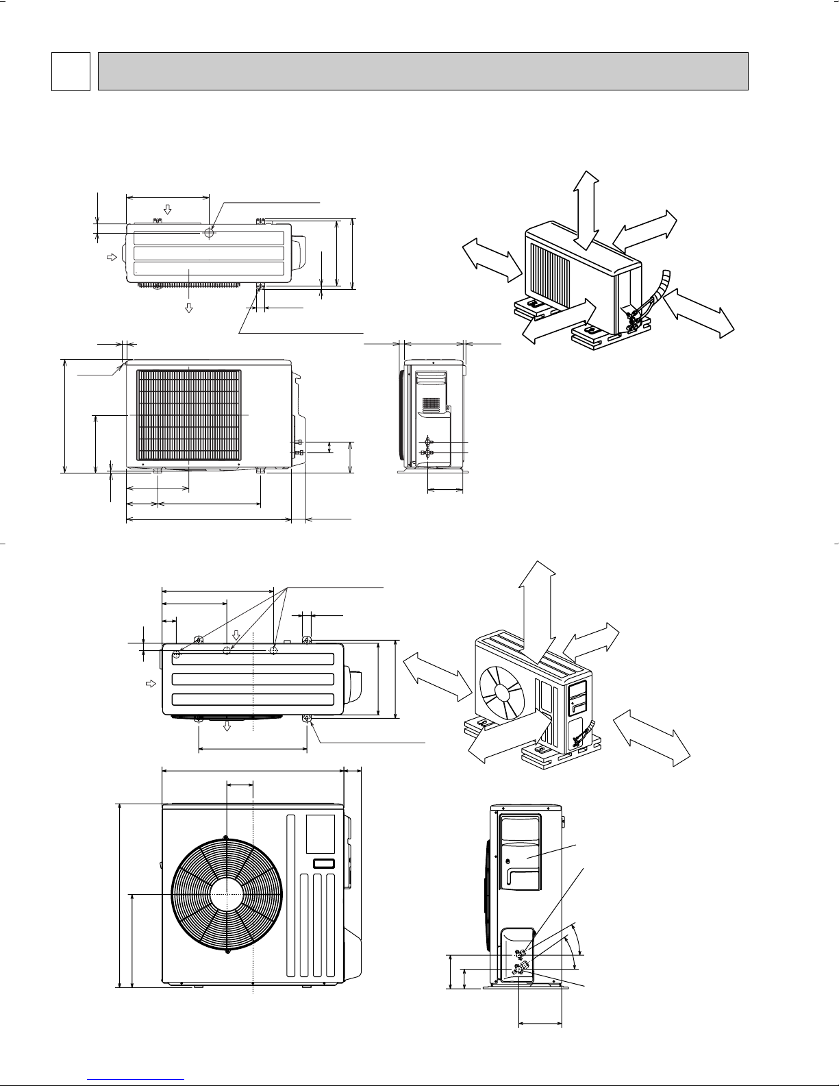
4
Liquid pipe :1/4 (flared)
Gas pipe :3/8 (flared) · · · MUZ-A09/12NA
:1/2 (flared) · · · MUZ-A15/17NA, MUY-A15/17NA
6-23/32
2
5-7/8
2-23/32
1-3/4
15-3/4
12 ~ 12-3/4
13-9/16
11/16
1-9/16
7/8
21-5/8
11-1/32
13/32
31-1/2
19-11/16
5-15/16
11-29/32
17/3229/32 11-1/4
Air in
handle
Air in
Air out
2- 3/8 o 13/16 Oval hole
Drainage hole [ 1-5/8
{
REQUIRED SPACE
Basically open 4inch or more
without any obstruction in front
and on both sides of the unit.
14 in.
or m
ore
8 in
. o
r m
o
re
4 in.
or more
4
in
. o
r m
o
re
Open two sides of left,
right, or rear side.
30-
3
5-
6-1/28
3-17/32
7-25/32
1-9/16
20-9/32
11-25/32
2-19/32
2
14-3/16
33-7/16
16-15/16
19-11/16
3-3/16
4-25/32
33-1/16
Open as a rule
20inch or more if
the front and both
sides are open
4inch or more
8inch or more if
there are obstacles
to both sides
Open as a rule
20inch or more if the back,
both sides and top are open
1
4
in
. o
r m
o
re
4
in
. o
r m
o
re
Air in
Air out
13
Service panel
Gas refrigerant
pipe joint
Refrigerant pipe
(flared) [5/8
Liquid refrigerant
pipe joint
Refrigerant pipe
(flared) [1/4
Drainage hole [ 1-5/8
4-3/8 o 13/16 Oval hole
REQUIRED SPACE
Air in
OUTLINES AND DIMENSIONS
MUZ-A09NA MUZ-A12NA MUZ-A15NA
MUZ-A17NA MUY-A15NA MUY-A17NA
Unit: inch
MUZ-A24NA MUY-A24NA
10
5
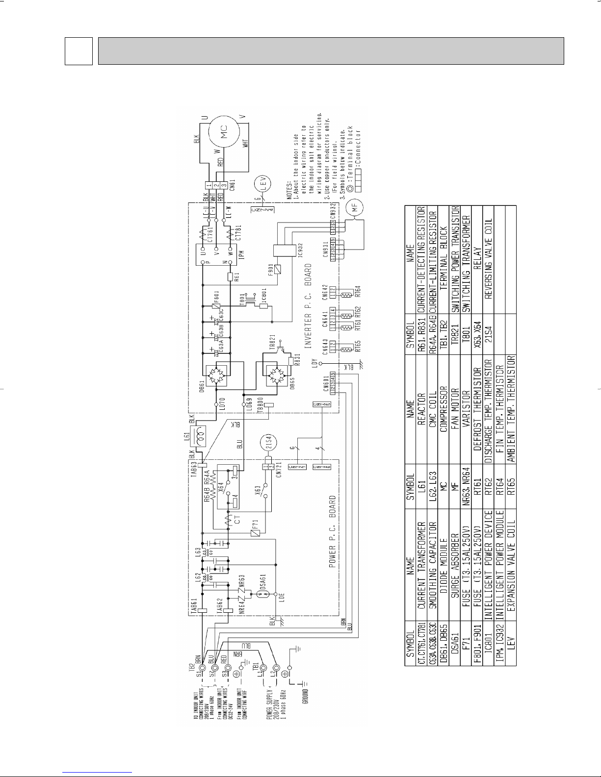
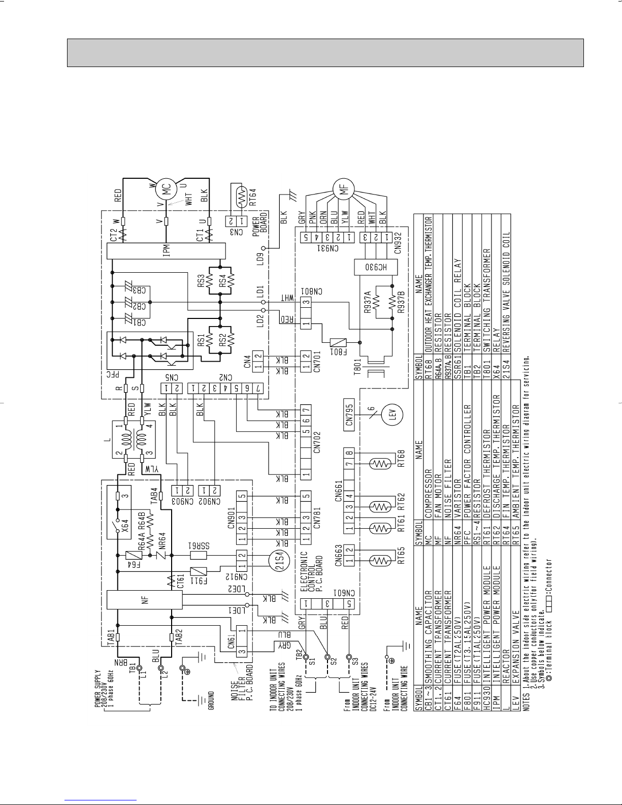
MUZ-A09NA MUZ-A12NA MUZ-A15NA MUZ-A17NA
WIRING DIAGRAM
11
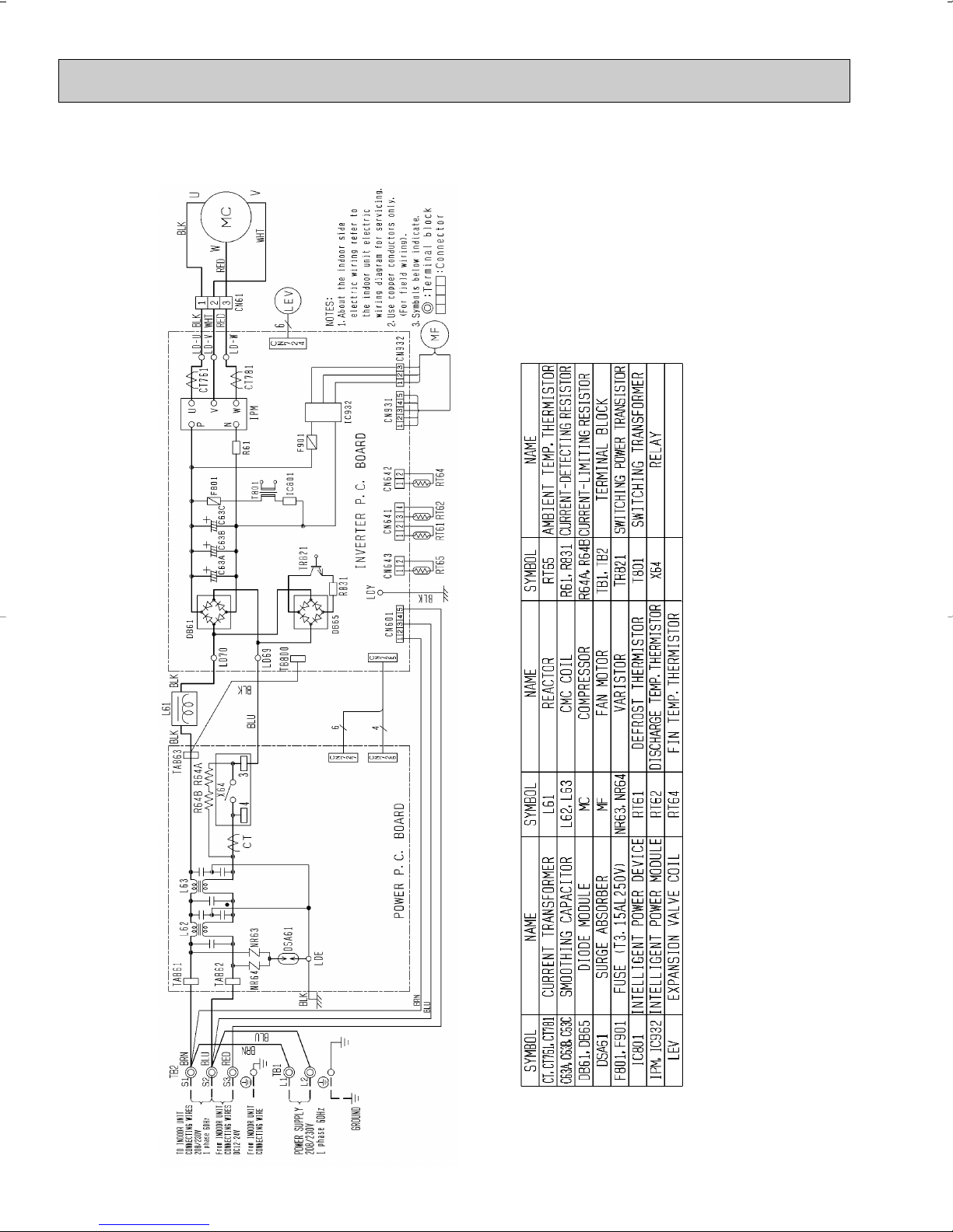
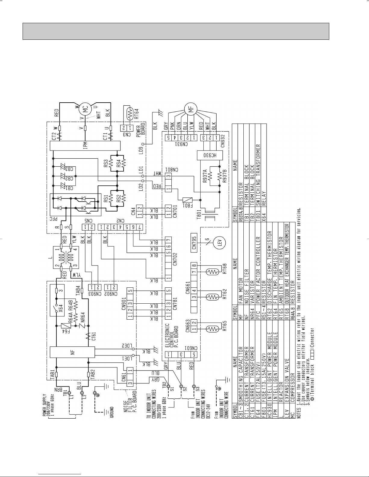
MUY-A15NA MUY-A17NA
12
MUZ-A24NA
13
MUY-A24NA
14
6
Outdoor
heat
exchanger
Flared connection
Defrost
thermistor
RT61
Discharge
temperature
thermistor
RT62
Service
port
Service
port
Flared connection
Stop valve
(with strainer)
Stop valve
(with service port)
Refrigerant flow in cooling
Compressor
4-way valve
Refrigerant flow in heating (MUZ)
Refrigerant pipe [3/8 (MUZ-A09/12)
[1/2 (MUZ-A15/17,MUY-A15/17)
(with heat insulator)
Refrigerant pipe [1/4
(with heat insulator)
R.V. coil
heating ON
cooling OFF
Strainer
#100
Capillary tube
O.D. 0.118 o I.D. 0.071
o 23-5/8
(
[3.0 o [1.8 o 600
)
Expansion
valve
Ambient
temperature
thermistor
RT65
Muffler
Muffler
Muffler
Outdoor
heat
exchanger
Flared connection
Defrost
thermistor
RT61
Service
port
Service
port
Discharge
temperature
thermistor
RT62
Flared connection
Stop valve
Stop valve
(with service port)
Capillary tube
Refrigerant flow in cooling
Compressor
4-way valve
Refrigerant flow in heating
Refrigerant pipe [5/8
(with heat insulator)
Refrigerant pipe [1/4
(with heat insulator)
LEV
R.V. coil
heating ON
cooling OFF
Muffler
#100
Strainer
#100
Receiver
Outdoor heat
exchanger
temperature
thermistor
RT68
Ambient
temperature
thermistor
RT65
Strainer
#100
O.D. 0.142 o I.D. 0.094
o 1-31/32
(
[3.6 o [2.4 o 50
)
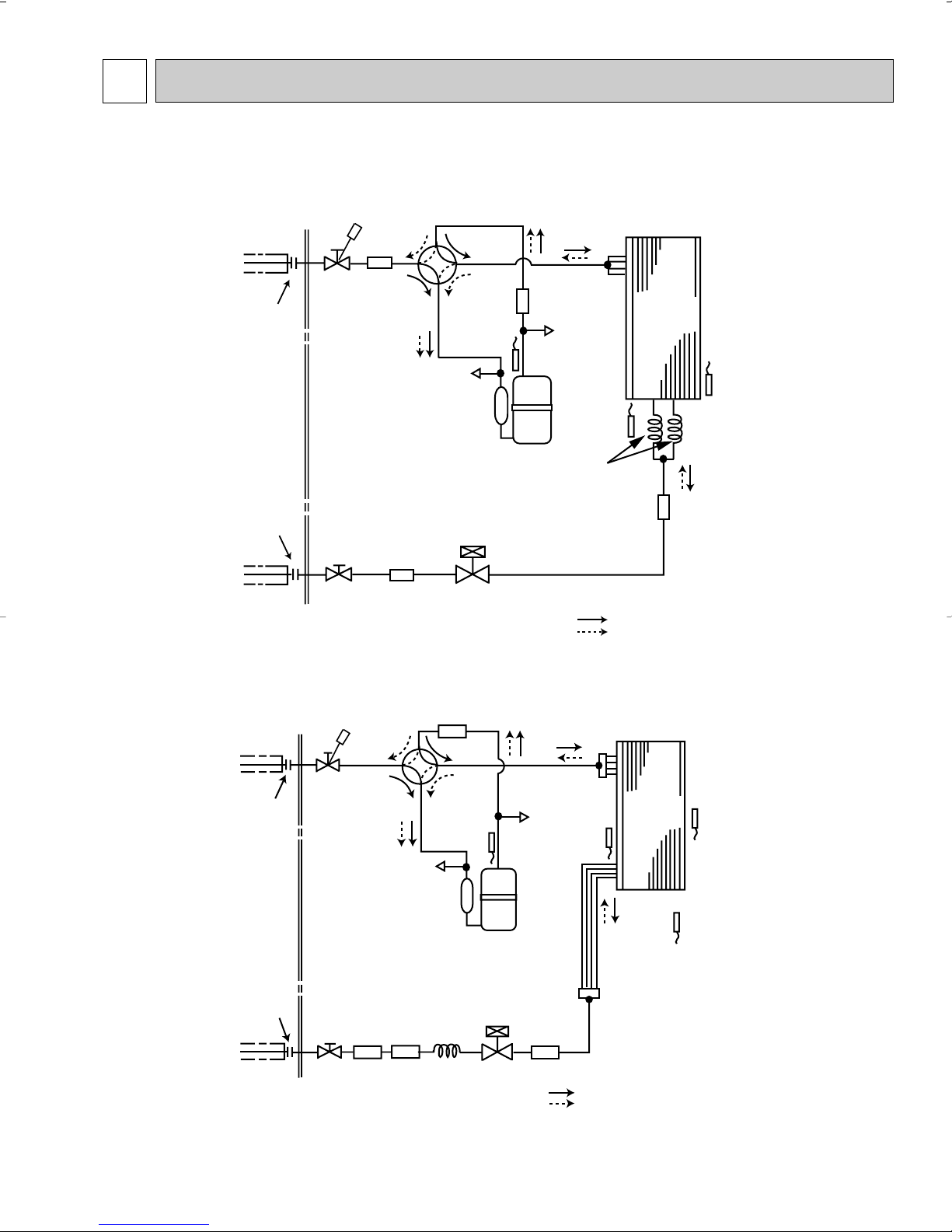
REFRIGERANT SYSTEM DIAGRAM
MUZ-A09NA MUZ-A15NA MUY-A15NA
MUZ-A12NA MUZ-A17NA MUY-A17NA
Unit:inch
MUZ-A24NA
15
Max. length
A
Max. Height
difference
B
Indoor
unit
Outdoor unit
Max. length
A
Max. Height difference
B
Model
Gas
Liquid
3/8
1/4
1/2
1/4
5/8
40
50
65
100
1/4
Piping size O.D : in
Refrigerant piping : ft
MUZ-A09NA
MUZ-A12NA
MUZ-A15NA
MUY-A15NA
MUZ-A17NA
MUY-A17NA
MUZ-A24NA
MUY-A24NA
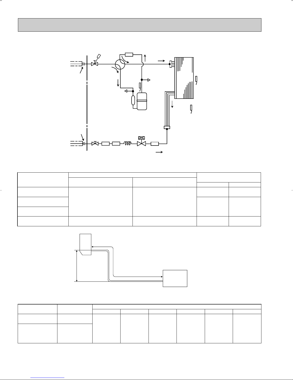
MUY-A24NA
Outdoor
heat
exchanger
Flared connection
Discharge
temperature
thermistor
RT62
Flared connection
Stop valve
Stop valve
(with service port)
Capillary tube
Refrigerant flow in cooling
Compressor
Service
port
Service
port
4-way valve
Refrigerant pipe [5/8
(with heat insulator)
Refrigerant pipe [1/4
(with heat insulator)
LEV
Muffler
#100
Strainer
#100
Receiver
Outdoor heat
exchanger
temperature
thermistor
RT68
Ambient
temperature
thermistor
RT65
Strainer
#100
O.D. 0.142 o I.D. 0.094
o 1-31/32
(
[3.6 o [2.4 o 50
)
Outdoor unit
precharged
3025 50
Model
Refrigerant piping length (one way) : ft
40
60 65
2lb.5oz.
2lb.7oz.
0 1.62 4.86 11.34 12.968.10
MUZ-A09NA
MUZ-A12NA
MUZ-A15NA
MUY-A15NA
MUZ-A17NA
MUY-A17NA
Calculation : Xoz. = 1.62/ 5oz./ ft o (Refrigerant piping length (ft)-25)
MAX. REFRIGERANT PIPING LENGTH and MAX. HEIGHT DIFFERENCE
Unit:inch
ADDITIONAL REFRIGERANT CHARGE (R410A:oz.)
Refrigerant piping exceeding 25ft. requires additional refrigterant charge according to the calculation.
16
7DATA
Model
Indoor air Outdoor intake air DB temperature(˚F
)
71
67
63
71
67
63
71
67
63
71
67
63
71
67
63
11.0
10.4
9.8
14.7
13.9
13.1
18.4
17.4
16.4
19.8
18.8
17.7
27.0
25.5
24.0
6.4
7.4
8.3
8.5
9.9
11.0
9.5
11.3
12.8
10.3
12.2
13.8
13.4
16.1
18.3
0.61
0.58
0.55
1.04
0.98
0.94
1.50
1.42
1.35
1.84
1.74
1.66
2.56
2.42
2.30
10.3
9.7
9.1
13.7
13.0
12.1
17.2
16.2
15.2
18.5
17.5
16.4
25.2
23.8
22.2
5.9
6.9
7.7
7.9
9.2
10.2
8.9
10.5
11.9
9.6
11.4
12.8
12.5
15.0
17.0
0.67
0.64
0.61
1.14
1.08
1.04
1.65
1.56
1.50
2.02
1.91
1.83
2.81
2.66
2.55
9.7
9.0
8.5
12.9
12.0
11.3
16.1
15.0
14.1
17.4
16.2
15.2
23.7
22.0
20.7
5.6
6.4
7.1
7.4
8.5
9.5
8.3
9.8
11.0
9.0
10.5
11.9
11.7
13.9
15.8
0.72
0.69
0.66
1.23
1.17
1.12
1.77
1.69
1.61
2.17
2.07
1.98
3.02
2.88
2.75
9.0
8.4
7.7
12.0
11.2
10.3
15.0
14.0
12.8
16.2
15.1
13.9
22.0
20.5
18.8
5.2
5.9
6.5
6.9
7.9
8.7
7.8
9.1
10.0
8.4
9.8
10.8
10.9
12.9
14.4
0.76
0.73
0.70
1.29
1.24
1.19
1.87
1.79
1.72
2.29
2.19
2.11
3.18
3.05
2.94
8.3
7.7
7.0
11.0
10.3
9.4
13.8
12.8
11.7
14.9
13.9
12.6
20.2
18.8
17.2
4.8
5.5
5.9
6.4
7.3
7.9
7.1
8.3
9.2
7.7
9.0
9.9
10.1
11.9
13.1
0.79
0.77
0.73
1.35
1.30
1.24
1.94
1.88
1.79
2.38
2.30
2.19
3.31
3.20
3.05
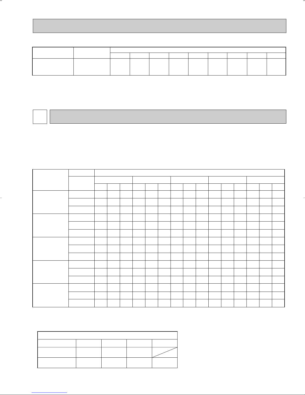
IWB
(˚F)
75 85 95 105 115
NOTE 1. IWB : Intake air wet-bulb temperature
TC : Total Capacity (x10
3
Btu/h), SHC : Sensible Heat Capacity (x10
3
Btu/h)
TPC : Total Power Consumption (kW)
2. SHC is based on 80˚F of indoor intake air DB temperature.
TC SHC
TPC TC SHC
TPC
TC SHC
TPC
TC SHC TPC
TC SHC
TPC
MSZ-A09NA
MSZ-A12NA
MSY-A15NA
MSY-A17NA
MSY-A24NA
MSZ-A15NA
MSZ-A17NA
MSZ-A24NA
Refrigerant piping length (one way : ft.)
1.0
25 (std.)
40
65
1.0
MSZ-A09/12/15/17NA
MSY-A15/17NA
MSZ-A24NA
MSY-A24NA
Model
0.954
0.95
0.878
0.878
100
0.713
50 60 70 80 90 100
Model
MUZ-A24NA
MUY-A24NA
Refrigerant piping length (one way) : ft
Outdoor unit
precharged
4lb. 0 1.08 3.24 5.40 7.56 9.72 11.88 14.04 16.20
25 30 40
Calculation : Xoz. = 1.08/ 5oz./ ft o (Refrigerant piping length (ft)-25)
NOTE : Refrigerant piping exceeding 25ft. requies additional refrigerant charge according to the calculation.
MUZ-A09NA MUZ-A12NA MUZ-A15NA
MUZ-A17NA MUZ-A24NA
MUY-A15NA MUY-A17NA MUY-A24NA
7-1. PERFORMANCE DATA
1) COOLING CAPACITY
2) COOLING CAPACITY CORRECTIONS
17
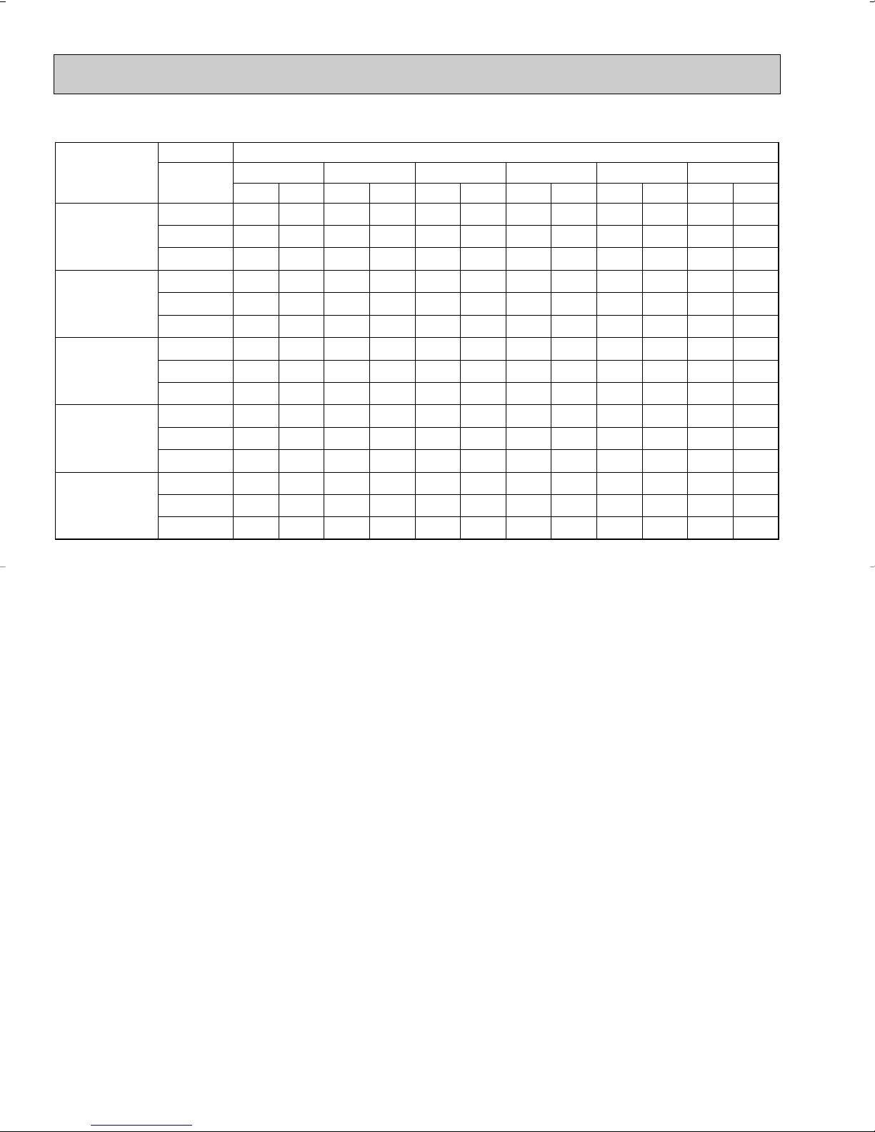
3) HEATING CAPACITY
Model
Indoor air Outdoor intake air WB temperature(˚F
)
75
70
65
75
70
65
75
70
65
75
70
65
75
70
65
6.3
6.7
6.9
7.9
8.4
8.6
10.4
11.1
11.3
11.7
12.4
12.7
13.5
14.3
14.6
0.64
0.62
0.59
0.86
0.84
0.80
1.33
1.29
1.24
1.60
1.55
1.48
1.75
1.69
1.62
7.9
8.2
8.6
9.9
10.2
10.7
13.1
13.5
14.1
14.6
15.1
15.8
16.8
17.4
18.2
0.75
0.74
0.71
1.02
0.99
0.96
1.57
1.53
1.48
1.88
1.84
1.77
2.06
2.01
1.94
9.4
9.6
10.0
11.8
12.0
12.4
15.6
15.9
16.5
17.4
17.8
18.4
20.1
20.5
21.2
0.84
0.82
0.80
1.13
1.10
1.07
1.75
1.70
1.66
2.10
2.04
1.99
2.29
2.23
2.17
10.6
10.9
11.2
13.3
13.6
14.0
17.6
18.0
18.5
19.6
20.1
20.7
22.6
23.2
23.9
0.88
0.86
0.84
1.19
1.16
1.13
1.83
1.79
1.75
2.20
2.15
2.10
2.41
2.35
2.29
11.0
11.2
11.6
13.7
14.0
14.4
18.1
18.5
19.1
20.2
20.7
21.3
23.3
23.9
24.6
0.89
0.88
0.85
1.21
1.18
1.15
1.86
1.83
1.77
2.24
2.19
2.13
2.44
2.40
2.33
12.4
12.7
13.0
15.5
15.8
16.2
20.5
21.0
21.4
22.9
23.4
23.9
26.4
27.0
27.6
0.93
0.91
0.89
1.25
1.23
1.21
1.93
1.90
1.86
2.32
2.28
2.24
2.54
2.49
2.44
IDB
(˚F)
15 25 35 43 45 55
MSZ-A09NA
MSZ-A12NA
MSZ-A15NA
MSZ-A17NA
MSZ-A24NA
NOTE: 1. IDB : Intake air dry-bulb temperature
TC : Total Capacity (x10
3
Btu/h)
TPC : Total Power Consumption (kW)
2. Above data is for heating operation without any frost.
TC TPC TC TPC TC TPC TC TPC TC TPC TC TPC
How to operate with fixed operational frequency of the compressor.
1. Press the EMERGENCY OPERATION switch on the front of the indoor unit, and select either EMERGENCY COOL mode
or EMERGENCY HEAT mode before starting to operate the air conditioner.
2. The compressor starts up.
The operational frequency of the compressor.
3. The fan speed of the indoor unit is High.
4. This operation continues for 30minutes.
5. In order to release this operation, press the EMERGENCY OPERATION switch twice or once, or press any button on the
remote controller.
18
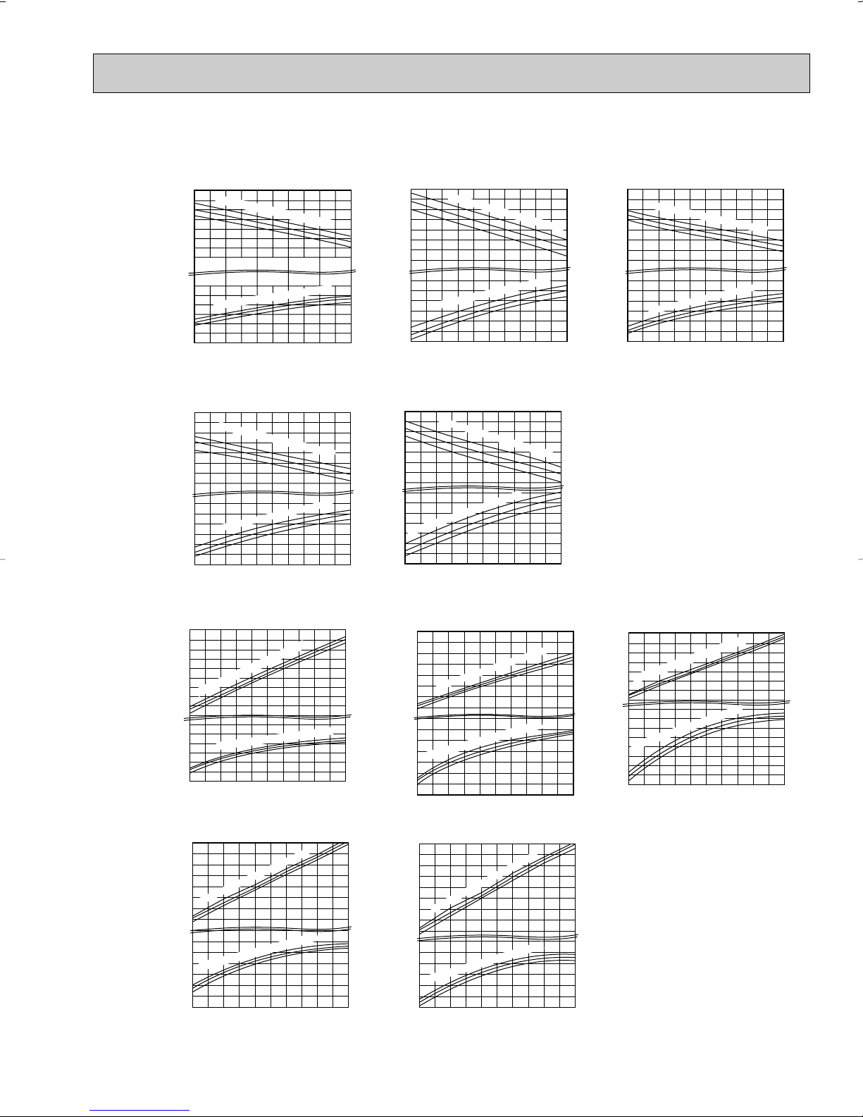
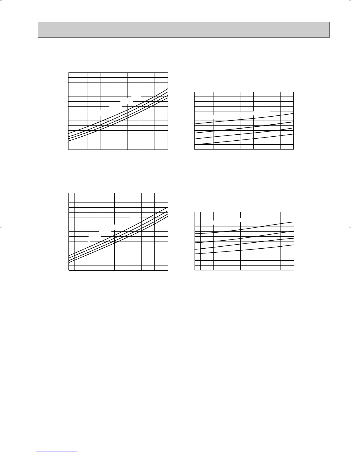
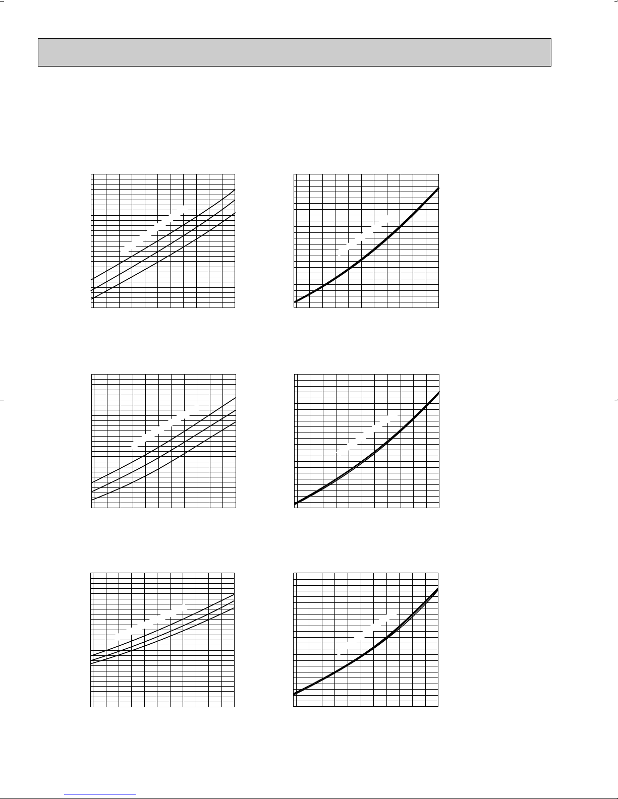
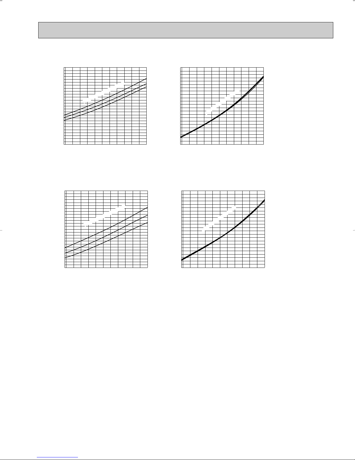
7-2. PERFORMANCE CURVE
65
70
75
75
70
65
Total power consumption
(kW)
Total capacity
( ✕10
3
Btu/h)
Outdoor intake air WB temperature (°F)
= 307CFM
Airflow
12
14
10
8
9
11
13
15
7
1.0
15 25 35 45 55
0.8
0.6
0.7
0.9
In
d
o
o
r in
ta
k
e
a
ir D
B
te
m
p
e
ra
tu
re
(
°F
)
In
d
o
o
r in
ta
ke
a
ir D
B
te
m
p
e
ra
tu
re
(
°F
)
65
70
75
75
70
65
20
12
8
16
22
18
10
14
In
d
o
o
r in
ta
k
e
a
ir D
B
te
m
p
e
ra
tu
re
(
°F
)
= 318CFM
Airflow
15 25 35 45 55
Outdoor intake air WB temperature (°F)
1.3
0.8
0.9
1.0
1.1
1.2
Indoor intake air DB temperature (
°F)
Total power consumption
(kW)
Total capacity
( ✕10
3
Btu/h)
65
70
75
75
70
65
Outdoor intake air WB temperature (°F)
= 381CFM
Airflow
18
22
24
14
10
1.8
1.9
1.7
15 25 35 45 55
1.5
1.3
1.4
1.6
I
n
d
o
o
r
in
t
a
k
e
a
ir
D
B
t
e
m
p
e
r
a
t
u
r
e
(
°
F
)
Indoor intake air D
B tem
perature (
°F)
Total power consumption
(kW)
Total capacity
( ✕10
3
Btu/h)
65
70
75
75
70
65
24
20
12
16
I
n
d
o
o
r
in
t
a
k
e
a
ir
D
B
t
e
m
p
e
r
a
t
u
r
e
(
°
F
)
= 381CFM
Airflow
15 25 35 45 55
Outdoor intake air WB temperature (°F)
2.4
1.4
1.6
1.8
2.0
2.2
Indoor intake air DB temperature (
°F)
Total power consumption
(kW)
Total capacity
( ✕10
3
Btu/h)
65
70
75
75
70
65
28
26
24
22
16
14
20
18
2.6
1.6
Indoor intake air DB temperature (
°F)
= 431CFM
Airflow
15 25 35 45 55
Outdoor intake air WB temperature (°F)
1.8
2.0
2.2
2.4
Indoor intake air DB temperature (°F)
Total power consumption
(kW)
Total capacity
( ✕10
3
Btu/h)
71
67
63
71
67
63
Outdoor intake air DB temperature (°F)
SHF at rating condition = 0.71
= 275CFM
Airflow
6
8
7
9
10
11
12
0.9
65 75 85 95 105 115
0.7
0.6
0.8
In
d
o
o
r
in
ta
k
e
a
ir W
B
te
m
p
e
r
a
tu
r
e
(
°
F
)
Indoor intake air WB temperature (
°F)
0.5
0.4
Total power consumption
(kW)
Total capacity
( ✕10
3
Btu/h)
71
67
63
71
67
63
24
22
20
18
12
16
14
2.5
2.3
2.1
1.9
1.7
1.5
In
d
o
o
r in
ta
k
e
a
ir W
B
te
m
p
e
ra
tu
re
(
°F
)
In
do
or in
ta
ke air W
B
te
m
pe
ra
tu
re (
°F
)
SHF at rating condition = 0.65
= 342CFM
Airflow
65 75 85 95 105 115
Outdoor intake air DB temperature (°F)
Total power consumption
(kW)
Total capacity
( ✕10
3
Btu/h)
71
63
67
71
63
67
27
29
23
19
25
21
17
3.1
2.9
2.7
2.5
2.3
2.1
Indoor intake air W
B
tem
perature (
°F)
Indoor intake air WB temperature (
°F)
SHF at rating condition = 0.63
= 385CFM
Airflow
65 75 85 95 105 115
Outdoor intake air DB temperature (°F)
Total power consumption
(kW)
Total capacity
( ✕10
3
Btu/h)
71
67
63
71
67
63
15
13
9
11
1.4
1.3
1.2
1.1
1.0
0.9
Indoor intake air WB temperature (
°F)
In
d
oo
r in
ta
k
e
a
ir W
B
te
m
pe
ra
tu
re
(
°F
)
SHF at rating condition = 0.70
= 318CFM
Airflow
65 75 85 95 105 115
Outdoor intake air DB temperature (°F)
Total power consumption
(kW)
Total capacity
( ✕10
3
Btu/h)
71
67
63
71
67
63
22
18
10
14
2.2
2.0
1.8
1.6
1.4
1.2
In
d
o
o
r in
ta
k
e
a
ir W
B
te
m
p
e
ra
tu
re
(
°
F
)
In
d
o
or in
ta
ke
a
ir W
B
te
m
p
e
ra
tu
re (
°F
)
SHF at rating condition = 0.65
= 342CFM
Airflow
65 75 85 95 105 115
Outdoor intake air DB temperature (°F)
Total power consumption
(kW)
Total capacity
( ✕10
3
Btu/h)
Cooling
MSZ-A09NA MSZ-A12NA
MSZ-A15NA MSY-A15NA
Heating
MSZ-A17NA MSY-A17NA
MSZ-A09NA
MSZ-A24NA MSY-A24NA
MSZ-A12NA
MSZ-A15NA
MSZ-A17NA
This value of frequency is not the same as the actual frequency in operating. Refer to 7-6 and 7-7 for the relationships
between frequency and capacity.
MSZ-A24NA
19
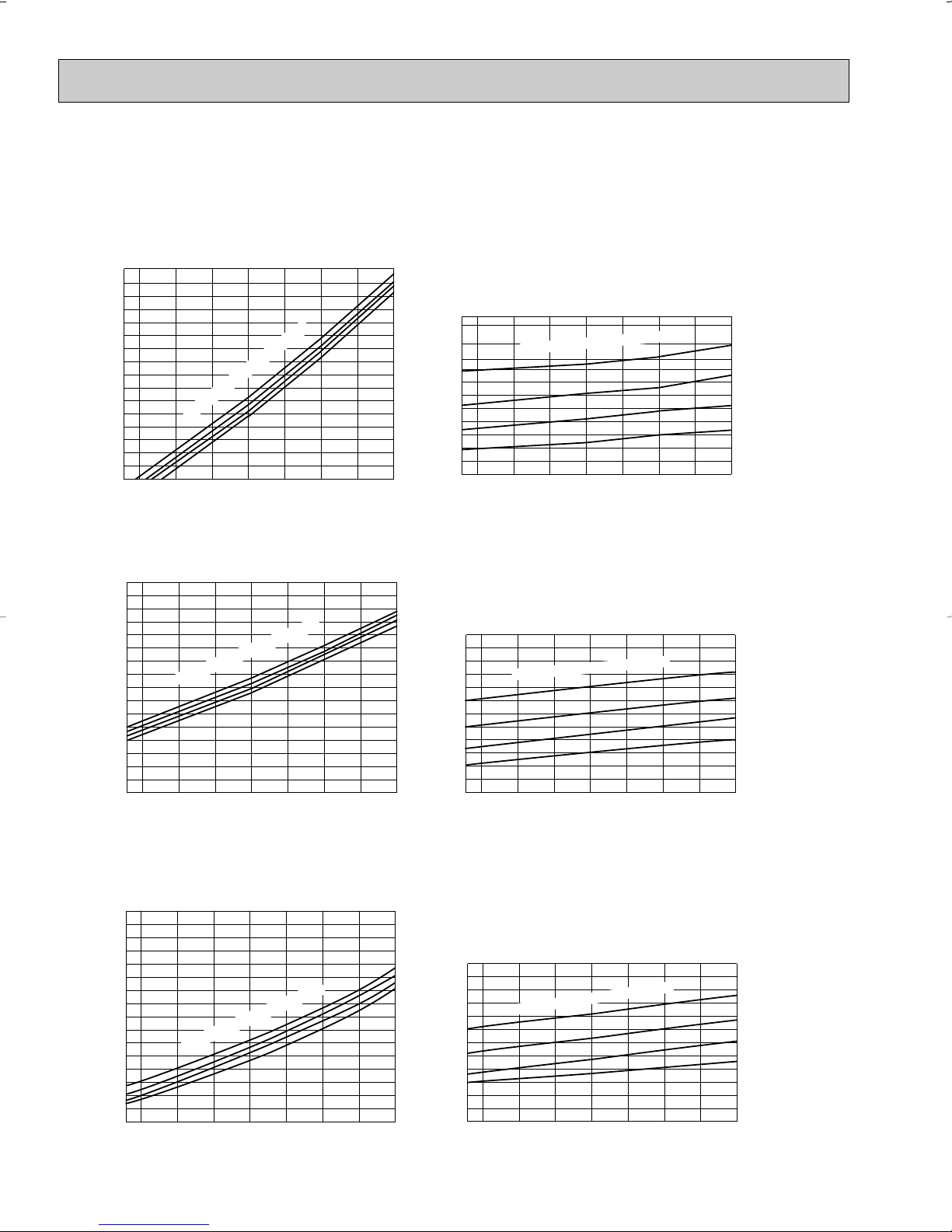
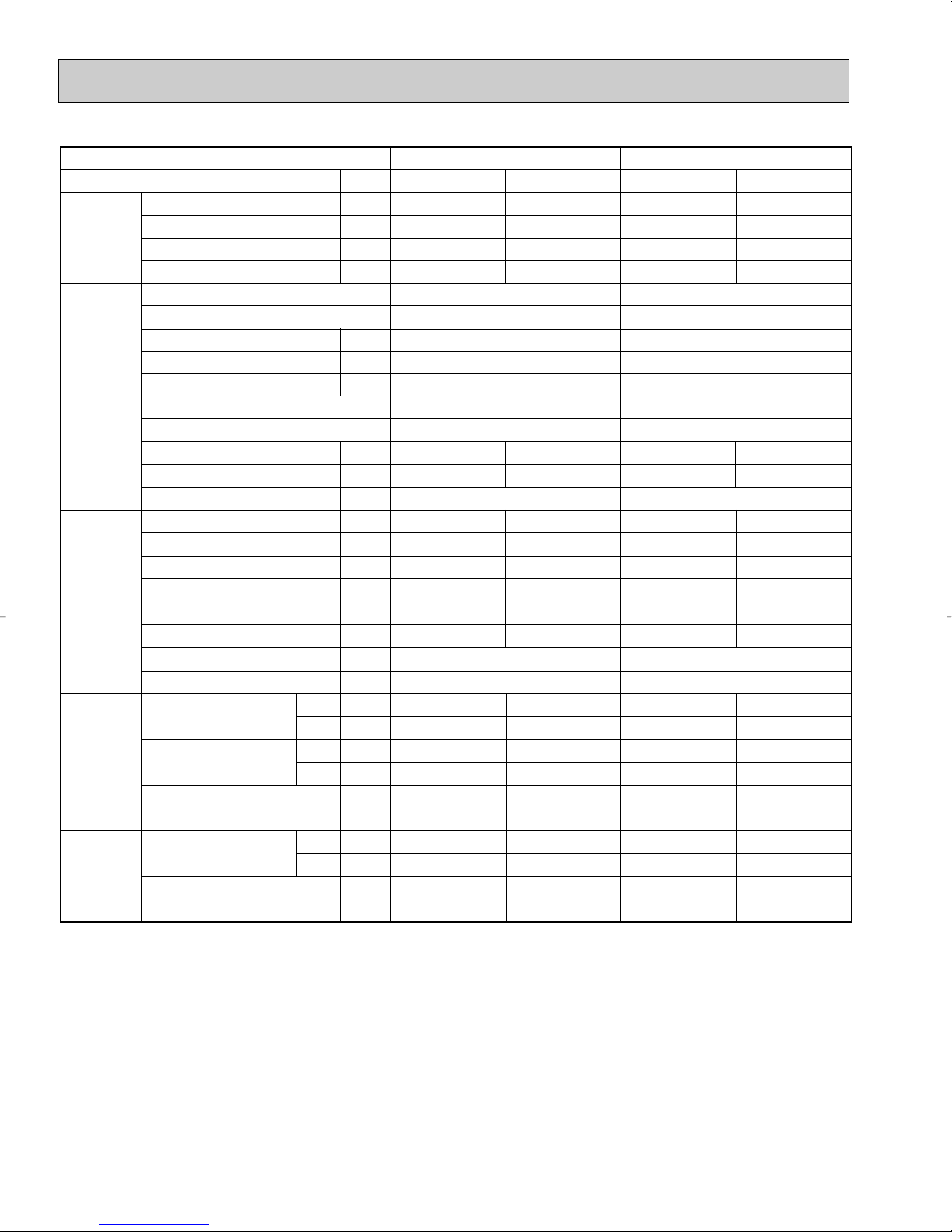
7-3. Condensing pressure
68 70 75 80 85 90 95 100 105
(°F)
110
115
120
125
130
135
140
145
150
155
160
165
170
(PSIG)
Condensing pressure
86
80
75
70
Suction pressure
Outdoor ambient temperature
Indoor DB temperature (
°F)
(PSIG)
86
80
75
70
68 70 75 80 85 90 95 100 105
(°F)
260
280
300
320
340
360
380
400
420
Indoor DB temperature (
°F)
Outdoor ambient temperature
68 70 75 80 85 90 95 100 105
(°F)
90
95
100
105
110
115
120
125
130
135
140
145
150
(PSIG)
Condensing pressure
86
80
75
70
Suction pressure
Outdoor ambient temperature
Indoor DB temperature (
°F)
(PSIG)
86
80
75
70
68 70 75 80 85 90 95 100 105
(°F)
180
220
260
300
340
380
420
460
500
Indoor D
B
tem
perature (
°F
)
Outdoor ambient temperature
68 70 75 80 85 90 95 100 105(°F)
80
85
90
95
100
105
110
115
120
125
130
135
140
(PSIG)
Condensing pressure
86
80
75
70
Suction pressure
Outdoor ambient temperature
Indoor DB temperature (°F)
(PSIG)
86
80
75
70
68 70 75 80 85 90 95 100 105(°F)
260
300
340
380
420
460
500
540
580
Indoor DB temperature (
°F)
Outdoor ambient temperature
Cooling
Data is based on the condition of indoor humidity 50%.
Air flow should be set to High speed.
MSZ-A09NA
MSZ-A12NA
MSZ-A15NA
MSY-A15NA
20
68 70 75 80 85 90 95 100 105(°F)
70
75
80
85
90
95
100
105
110
115
120
125
130
(PSIG)
Condensing pressure
86
80
75
70
Suction pressure
Outdoor ambient temperature
Indoor DB temperature (
°F)
(PSIG)
86
80
75
70
68 70 75 80 85 90 95 100 105(°F)
260
300
340
380
420
460
500
540
580
Indoor D
B tem
perature (
°F
)
Outdoor ambient temperature
MSZ-A17NA
(PSIG)
Condensing pressure
86
80
75
70
68 70 75 80 85 90 95 100 105(°F)
80
85
90
95
100
105
110
115
120
125
130
135
140
Suction pressure
Outdoor ambient temperature
Indoor DB temperature (
°F)
(PSIG)
86
80
75
70
68 70 75 80 85 90 95 100 105(°F)
260
300
340
380
420
460
500
540
580
Indoor DB temperature (
°F)
Outdoor ambient temperature
MSY-A17NA
MSZ-A24NA
MSY-A24NA
21
Heating
75
70
65
(PSIG) (PSIG)
Condensing pressure
Outdoor ambient temperature
14 20 25 30 35 40 45 50 55 60 65 70(°F)
340
320
300
280
260
240
360
380
400
440
420
460
480
Indoor DB temperature(
°F)
75
70
65
Suction pressure
Outdoor ambient temperature
14 20 25 30 35 40 45 50 55
58Hz
58Hz
60 65 70(°F)
70
60
80
90
100
110
120
130
140
150
160
170
In
d
o
o
r D
B
te
m
p
e
ra
tu
re
(
°
F
)
75
70
65
(PSIG) (PSIG)
Condensing pressure
Outdoor ambient temperature
14 20 25 30 35 40 45 50 55 60 65 70(°F)
260
220
180
140
100
300
340
380
460
420
500
540
580
620
In
d
o
o
r D
B
te
m
p
e
ra
tu
re
(°
F
)
75
70
65
Suction pressure
Outdoor ambient temperature
14 20 25 30 35 40 45 50 55
58Hz
58Hz
60 65 70(°F)
70
60
50
80
90
100
110
120
130
140
150
160
In
d
o
o
r
D
B
te
m
p
e
ra
tu
re
(
°
F
)
75
70
65
(PSIG) (PSIG)
Condensing pressure
Outdoor ambient temperature
14 20 25 30 35 40 45 50 55 60 65 70(°F)
340
320
300
280
260
240
360
380
400
440
420
460
480
Indoor DB temperature(
°F)
75
70
65
Suction pressure
Outdoor ambient temperature
14 20 25 30 35 40 45 50 55
58Hz
58Hz
60 65 70(°F)
70
60
80
90
100
110
120
130
140
150
160
170
In
d
o
o
r D
B
te
m
p
e
ra
tu
re
(
°
F
)
Data is based on the condition of outdoor humidity 75%.
Air flow should be set to High speed.
Data is for heating operation without any frost.
MSZ-A09NA
MSZ-A12NA
MSZ-A15NA
22
MSZ-A17NA
75
70
65
(PSIG) (PSIG)
Condensing pressure
Outdoor ambient temperature
14 20 25 30 35 40 45 50 55 60 65 70(°F)
260
220
180
140
100
300
340
380
460
420
500
540
580
620
In
d
o
o
r D
B
te
m
p
e
ra
tu
re
(°
F
)
75
70
65
Suction pressure
Outdoor ambient temperature
14 20 25 30 35 40 45 50 55
58Hz
58Hz
60 65 70(°F)
70
60
50
80
90
100
110
120
130
140
150
160
In
d
o
o
r D
B
te
m
p
e
ra
tu
re
(
°
F
)
75
70
65
(PSIG) (PSIG)
Condensing pressure
Outdoor ambient temperature
14 20 25 30 35 40 45 50 55 60 65 70(°F)
280
260
240
220
200
300
320
340
380
360
400
420
440
460
In
d
o
o
r D
B
te
m
p
e
ra
tu
re
(°
F
)
75
70
65
Suction pressure
Outdoor ambient temperature
14 20 25 30 35 40 45 50 55
58Hz
60 65 70(°F)
70
60
50
80
90
100
110
120
130
140
150
160
In
d
o
o
r D
B
te
m
p
e
ra
tu
re
(
°
F
)
58Hz
MSZ-A24NA
23
7-4. STANDARD OPERATION DATA
Capacity
SHF
Input
Rated frequency
Indoor unit
Power supply (V, phase, Hz)
Input
Fan motor current
Aux. heater current
Outdoor unit
Power supply (V, phase, Hz)
Input
Comp. current
Fan motor current
Condensing pressure
Suction pressure
Discharge temperature
Condensing temperature
Suction temperature
Comp. shell bottom temp
Ref. pipe length
Refrigerant charge (R410A)
Intake air temperature
Discharge air temperature
Fan speed (High)
Airflow (High)
Intake air temperature
Fan speed
Airflow
Unit
Btu / h
—
kW
Hz
kW
A
A
kW
A
A
PSIG
PSIG
˚F
˚F
˚F
˚F
ft.
—
˚F
˚F
˚F
˚F
rpm
CFM
˚F
˚F
rpm
CFM
Cooling
9,000
0.71
0.690
50
0.674
2.80 / 2.53
363
144
145
107
55
140
80
67
57
56
1,080
275 (Wet)
95
–
840
1,094
Cooling
12,000
0.70
1,170
76
1.149
5.08 / 4.59
395
124
169
112
54
163
80
67
56
54
1,220
318 (Wet)
95
–
840
1,094
Heating
10,900
–
0.860
61
0.844
3.63 / 3.28
368
109
153
108
37
147
70
60
105
71
1,080
307
47
43
840
1,094
Heating
13,600
–
1,160
76
1.139
5.03 / 4.54
393
103
164
113
35
158
70
60
108
72
1,220
353
47
43
840
1,094
DB
WB
DB
WB
DB
WB
Item
Model
Total
Electrical
circuit
Refrigerant
circuit
Indoor
unit
Outdoor
unit
MSZ-A09NA
MSZ-A09NA
208/230, 1, 60
0.016
0.18 / 0.16
–
MUZ-A09NA
208/230, 1, 60
0.37 / 0.34
25
2lb.5oz.
MSZ-A12NA
MSZ-A12NA
208/230, 1, 60
0.021
0.23 / 0.21
–
MUZ-A12NA
208/230, 1, 60
0.37 / 0.34
25
2lb.5oz.
24
 Loading...