

Page 1
HFC
utilized
R410A
SPLIT-TYPE, AIR CONDITIONERS
SPLIT-TYPE, HEAT PUMP AIR CONDITIONERS
Revision:
●MXZ-A18WV - have been added.
●MSC-A07/09/12WV - Part No..have changed.
VARISTOR (NR11& NR12)
E02 336 385 ➔ E02 749 385
●Please void OB307.
E1
E1
SERVICE MANUAL
Wireless type
Models
MSC-A07WV MSC-A09WV MSC-A12WV MSC-A07WV MSC-A09WV MSC-A12WV -
Multi system type
Models
MSC-A07WV MSC-A09WV MSC-A12WV -
Inverter-controlled multi system Model
(WH)
(WH)
(WH)
(WH)
(WH)
(WH)
(WH)
(WH)
(WH)
· MU-A07WV -
· MU-A09WV -
· MU-A12WV -
· MUH-A07WV -
· MUH-A09WV -
· MUH-A12WV -
· MUX-A10WV -
· MUX-A19WV -
· MUX-A20WV -
· MUX-A25WV -
· MUX-A26WV -
· MXZ-A18WV -
REVISED EDITION-A
No. OB307
E1E1
E1E1
E1E1
E1E1
E1E1
E1E1
E1E1
E1E1
E1E1
E1
E1
E1
MSC-A07WV MSC-A09WV MSC-A12WV -
Remote
controller
E1
E1
E1
Indication of
model name
CONTENTS
1. TECHNICAL CHANGES ····································2
2. PART NAMES AND FUNCTIONS······················6
3. INDOOR/OUTDOOR
CORRESPONDENCE TABLE ···························8
4. INDOOR UNITS COMBINATION ·······················9
5. SPECIFICATION···············································10
6. NOISE CRITERIA CURVES···························· 17
7. OUTLINES AND DIMENSIONS······················ 20
8. WIRING DIAGRAM ··········································25
9. REFRIGERANT SYSTEM DIAGRAM··············32
10. PERFORMANCE CURVES······························45
11. MICROPROCESSOR CONTROL·····················84
12. SERVICE FUNCTIONS···································102
13. TROUBLESHOOTING····································104
14. DISASSEMBLY INSTRUCTIONS···················129
15. PARTS LIST····················································144
16. OPTIONAL PARTS ·········································157
Page 2
1
TECHNICAL CHANGES
MSC-07RV- ➔MSC-A07WVMSC-09RV- ➔MSC-A09WVMSC-12RV- ➔MSC-A12WV-
1. Rated voltage has changed. (220-240V➔230V)
2. Indoor model has changed.
MU-07RV- ➔MU-A07WV-
1. Refrigerant has changed. (R22➔R410A)
2. Compressor has changed. (RH130VGCT➔RN092VHSHT)
MU-09RV- ➔MU-A09WV-
1. Refrigerant has changed. (R22➔R410A)
2. Compressor has changed. (RH140VGCT➔RN099VHSHT)
MU-12RV- ➔MU-A12WV-
1. Refrigerant has changed. (R22➔R410A)
2. Compressor has changed. (RH220VHAT➔RN135VHSHT)
MUH-07RV- ➔MUH-A07WV-
1. Refrigerant has changed. (R22➔R410A)
2. Compressor has changed. (RH130VGCT➔RN092VHSHT)
MUH-09RV- ➔MUH-A09WV-
1. Refrigerant has changed. (R22➔R410A)
2. Compressor has changed. (RH165VGCT➔RN104VHSHT)
E1E4
E1E4
E1E4
E1E4
E1E4
E1E4
E1E4
E1E4
MUH-12RV- ➔MUH-A12WV-
1. Refrigerant has changed. (R22➔R410A)
2. Compressor has changed. (RH220VHAT➔RN135VHSHT)
MUX-10RV- ➔MUX-A10WV-
1. Outdoor model has changed.
2. Refrigerant has changed. (R22➔R410A)
MUX-19TV- ➔MUX-A19WVMUX-20TV- ➔MUX-A20WVMUX-25TV- ➔MUX-A25WV-
1. Refrigerant has changed. (R22➔R410A)
MUX-24RV- ➔MUX-A26WV-
1. Outdoor model has changed.
2. Refrigerant has changed. (R22➔R410A)
MXZ-18TV - ➔ MXZ-A18WV -
• Outdoor model has changed.
• Refrigerant has changed.
E1E4
E1E2
E1E1
E1E1
E1E1
E1E2
E1E2
2
Page 3

Refrigerating
oil
Refrigerant
New refrigerant
R410A
HFC-32: HFC-125 (50%:50%)
Pseudo-azeotropic refrigerant
Not included
A1/A1
72.6
-51.4
1.557
64
Non combustible
0
1730
From liquid phase in cylinder
Possible
Incompatible oil
Non
Non
Previous refrigerant
R22
R22 (100%)
Single refrigerant
Included
A1
86.5
-40.8
0.94
44.4
Non combustible
0.055
1700
Gas phase
Possible
Compatible oil
Light yellow
Non
Refrigerant
Composition (Ratio)
Refrigerant handling
Chlorine
Safety group (ASHRAE)
Molecular weight
Boiling point (:)
Steam pressure [25:](Mpa)
Saturated steam density [25:](Kg/K)
Combustibility
ODP w1
GWP w2
Refrigerant charge method
Additional charge on leakage
Kind
Color
Smell
w1:Ozone Destruction Parameter : based on CFC-11
w2 :Global Warmth Parameter : based on CO
2
INFORMATION FOR THE AIR CONDITIONER WITH R410A REFRIGERANT
New Specification Current Specification
The incompatible refrigerating oil easily separates from
refrigerant and is in the upper layer inside the suction muffler.
Raising position of the oil back hole enables to back the
refrigerating oil of the upper layer to flow back to the
compressor.
Since refrigerant and refrigerating oil are compatible each,
refrigerating oil backs to the compressor through the lower
position oil back hole.
Compressor
Suction muffler
Oil back hole
Refrigerating oil
Refrigerant
Compressor
Suction muffler
Oil back hole
Refrigerating oil /Refrigerant
Compressor
• This room air conditioner adopts an HFC refrigerant (R410A) which never destroys the ozone layer.
• Pay particular attention to the following points, though the basic installation procedure is same as that for R22 conditioners.
1 As R410A has working pressure approximate 1.6 times as high as that of R22, some special tools and piping parts/
materials are required. Refer to the table below.
2 Take sufficient care not to allow water and other contaminations to enter the R410A refrigerant during storage and
installation, since it is more susceptible to contaminations than R22.
3 For refrigerant piping, use clean, pressure-proof parts/materials specifically designed for R410A. (Refer to 2. Refrigerant
piping.)
4 Composition change may occur in R410A since it is a mixed refrigerant. When charging, charge liquid refrigerant to prevent
composition change.
NOTE : The unit of pressure has been changed to MPa on the international system of units(SI unit system).
The conversion factor is: 1(MPa [Gauge]) =10.2(kgf/ff[Gauge])
3
Page 4
-30 -20 -10 0 10 20
30
40 50 60
-0.5
0.0
0.5
1.0
1.5
2.0
2.5
3.0
3.5
4.0
(MPa [Gauge])
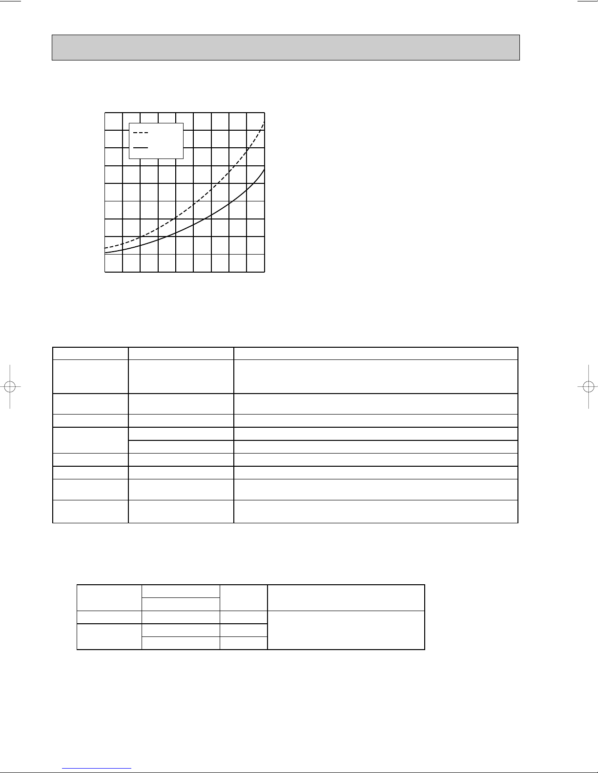
R410A
R22
Conversion chart of refrigerant temperature and pressure
Saturated liquid pressure
(:)
NOTE : The unit of pressure has been changed to MPa on the
R410A tools Can R22 tools be used?
Gas leak detector
R410A has high pressures beyond the measurement range of existing
gauges. Port diameters have been changed to prevent any other refrigerant
from being charged into the unit.
Hose material and cap size have been changed to improve the pressure
resistance.
Dedicated for HFC refrigerant.
6.35 mm and 9.52 mm
Description
Clamp bar hole has been enlarged to reinforce the spring strength in the tool.
Provided for flaring work (to be used with R22 flare tool).
Provided to prevent the back flow of oil. This adapter enables you to use
vacuum pumps.
It is difficult to measure R410A with a charging cylinder because the
refrigerant bubbles due to high pressure and high-speed vaporization
No
No
No
Yes
Yes
New
New
New
Gauge manifold
Charge hose
Torque wrench
Flare tool
Flare gauge
Vacuum pump
adapter
Electronic scale for
refrigerant charging
No : Not Substitutable for R410A Yes : Substitutable for R410A
No 12.7 mm
Wall
thickness
Outside diameter
Pipe
mm
For liquid
For gas
6.35
9.52
12.7
0.8 mm
0.8 mm
0.8 mm
Heat resisting foam plastic
Specific gravity 0.045 Thickness 8 mm
Insulation material
international system of units(SI unit system).
The conversion factor is: 1(MPa [Gauge]) =10.2(kgf/ff[Gauge])
1.Tools dedicated for the air conditioner with R410A refrigerant
The following tools are required for R410A refrigerant. Some R22 tools can be substituted for R410A tools.
The diameter of the service port on the stop valve in outdoor unit has been changed to prevent any other refrigerant being
charged into the unit. Cap size has been changed from 7/16 UNF with 20 threads to 1/2 UNF with 20 threads.
2.Refrigerant piping
1 Specifications
Use the refrigerant pipes that meet the following specifications.
• Use a copper pipe or a copper-alloy seamless pipe with a thickness of 0.8 mm. Never use any pipe with a thickness less
than 0.8mm, as the pressure resistance is insufficient.
4
Page 5
2 Flaring work and flare nut
Flaring work for R410A pipe differs from that for R22 pipe.
For details of flaring work, refer to Installation manual “FLARING WORK”.
Pipe diameter
mm
6.35
9.52
12.7
Dimension of flare nut
R410A
17
22
26
R22
17
22
24
3.Refrigerant oil
Apply the special refrigeration oil (accessories: packed with indoor unit) to the flare and the union seat surfaces.
4.Air purge
• Do not discharge the refrigerant into the atmosphere.
Take care not to discharge refrigerant into the atmosphere during installation, reinstallation, or repairs to the refrigerant
circuit.
• Use the vacuum pump for air purging for the purpose of environmental protection.
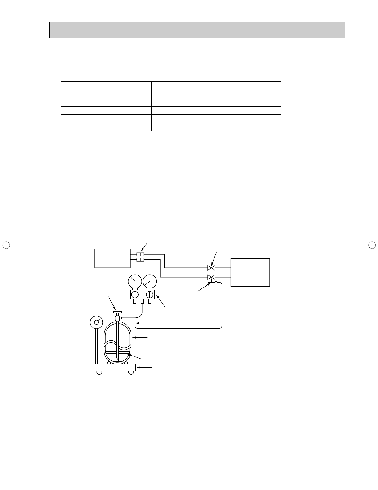
5.Additional charge
For additional charging, charge the refrigerant from liquid phase of the gas cylinder.
If the refrigerant is charged from the gas phase, composition change may occur in the refrigerant inside the cylinder and the
outdoor unit. In this case, ability of the refrigerating cycle decreases or normal operation can be impossible. However,
charging the liquid refrigerant all at once may cause the compressor to be locked. Thus, charge the refrigerant slowly.
Union
Stop valve
Indoor unit
Refrigerant gas
cylinder
operating valve
Liquid pipe
Gas pipe
Service port
Outdoor unit
Gauge manifold
valve (for R410A)
Charge hose (for R410A)
Refrigerant gas cylinder
for R410A with siphon
Refrigerant (liquid)
Electronic scale for refrigerant charging
5
Page 6

2
PART NAMES AND FUNCTIONS
INDOOR UNIT
MSC-A07WV MSC-A09WV MSC-A12WV -
E1
E1
E1
Air cleaning filter
(White bellows type)
Deodorizing filter
(Gray sponge type)
Panel
Air filter
Air outlet
Vertical vane
Horizontal vane
Operation section
(When the front panel is opened)
Emergency operation switch
Front panel
Air inlet
to Breaker
Power supply cord
Remote control
receiving section
Remote controller
Display section
Operation indicator lamp
Receiving section
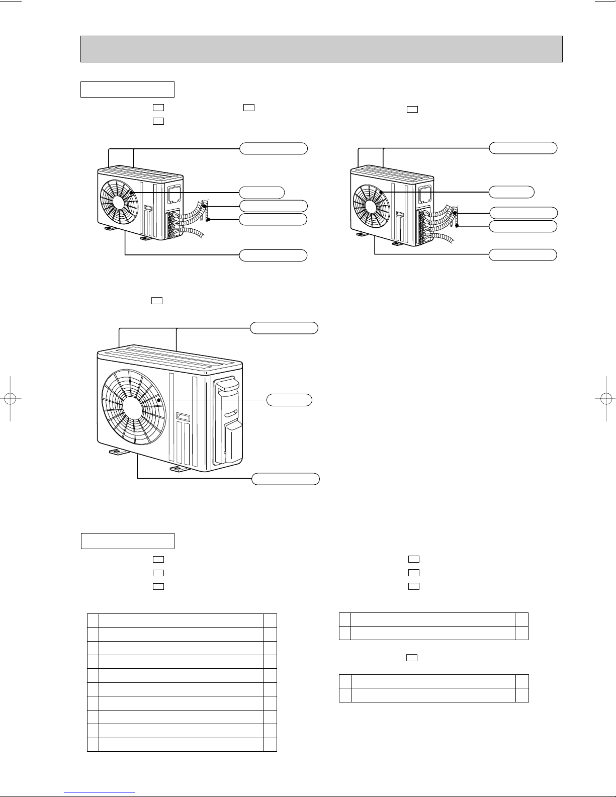
OUTDOOR UNIT
MU-A07WV - MUH-A07WV MU-A09WV - MUH-A09WV MU-A12WV - MUH-A12WV -
Air inlet
(back and side)
Piping
Air outlet
Drain outlet
E1E1
E1E1
E1E1
Drain hose
MUX-A10WV-
6
E1
Air inlet
(back and side)
Piping
Drain hose
Air outlet
Drain outlet
Page 7
OUTDOOR UNIT
Installation plate
Installation plate fixing screw 4 o 25 mm
Remote controller holder
Fixing screw for 3 3.5 o 16 mm
Battery (AAA) for remote controller
Wireless remote controller
Felt tape (Used for left or left-rear piping)
Deodorizing filter
Air cleaning filter
Refrigerant oil
1
5
1
2
2
1
1
1
1
1
<Indoor unit>
1
2
3
4
5
6
7
8
9
0
Drain socket
Drain cap
1
2
<Outdoor unit: MUH type>
1
2
Air outlet
Drain outlet
Air inlet
(Back and side)
MUX-A19WV- MUX-A25WVMUX-A20WV-
E1
E1E1
MUX-A26WV-
E1
MXZ-A18WV-
Air inlet
(Back and side)
Air outlet
Piping
Drainage hose
Drain outlet
E1
Air inlet
(Back and side)
Air outlet
Piping
Drainage hose
Drain outlet
ACCESSORIES
MSC-A07WVMSC-A09WVMSC-A12WV-
E1
E1
E1
MUH-A07WVMUH-A09WVMUH-A12WV-
MXZ-A18WV-
1
Drain socket
2
Drain cap
7
E1
E1
E1
E1
1
2
Page 8
MUX-A19WV-
E1
MUX-A25WV-
E1
MUX-A20WV-
E1
MUX-A10WV-
E1
MUX-A26WV-
E1
Combination of
the connectable
indoor units
OUTDOOR UNIT
A: MSC-A12WV- E1
B: MSC-A07WV-
E1
A:
B:
MSC-A09WV- E1
C:
A:
MSC-A07WV- E1
B:
A:
MSC-A12WV- E1
B:
C:
MSC-A09WV- E1
D:
A:
MSC-A12WV- E1
B:
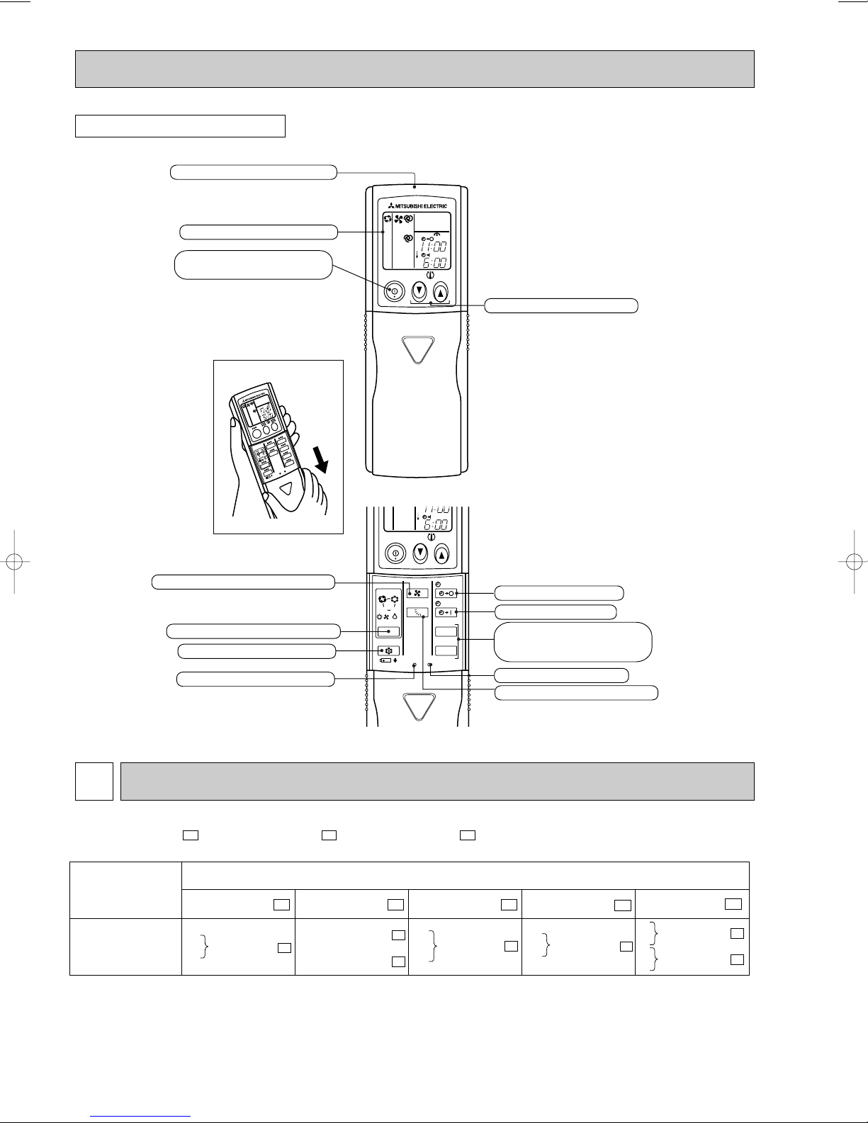
REMOTE CONTROLLER
Signal transmitting section
Operation display section
OPERATE /STOP
(ON /OFF)button
Open the front lid.
FAN SPEED CONTROL button
OPERATION SELECT button
ECONO COOL button
RESET button
ON/OFF
ON/OFF
I FEEL
COOL
VANE
HEAT
DRY
/FAN
/
MODE
ECONO COOL
RESET
TOO
WARM
TOO
WARM
FAN
CLOCK
CLOCK
PM
AM
TOO
COOL
PM
AM
TOO
COOL
STOP
START
HR.
MIN.
TEMPERATURE buttons
OFF-TIMER button
ON-TIMER button
HR. button
MIN. button
(TIME SET button)
CLOCK SET button
VANE CONTROL button
INDOOR/ OUTDOOR CORRESPONDENCE TABLE3
MSC-A07WV - MSC-A09WV - MSC-A12WV -
E1E1E1
8
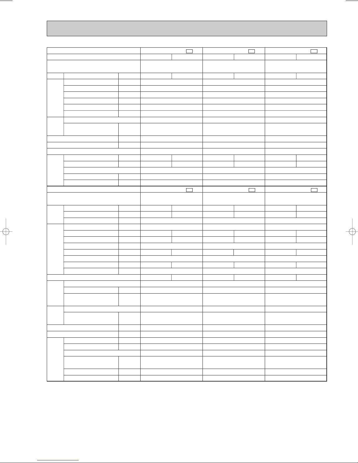
Page 9
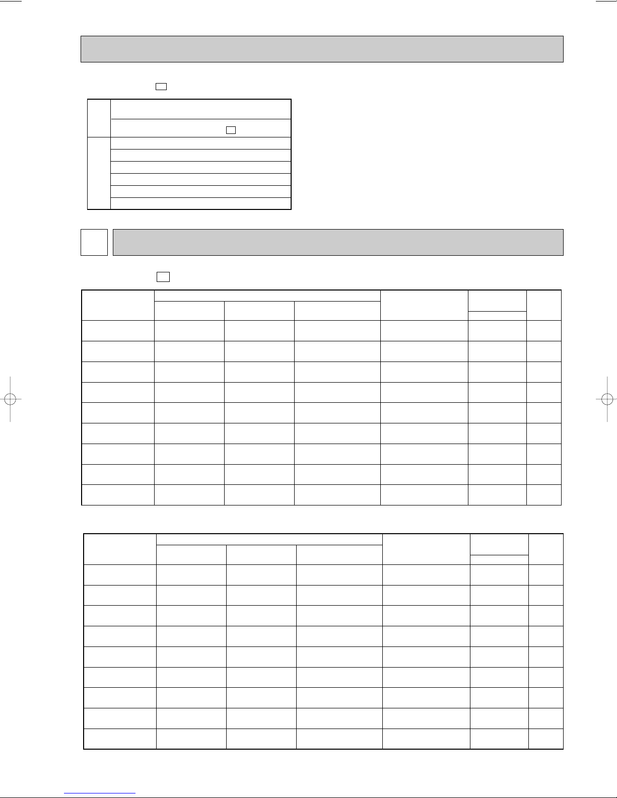
07
09
12
07+07
07+09
07+12
09+09
09+12
12+12
90
90
90
90
90
90
90
90
90
3.62
3.91
5.70
7.15
7.73
7.78
8.60
8.84
8.99
2.3
(0.9-2.95)
2.5
(0.9-3.30)
3.4
(0.9-4.00)
4.6
(1.49-5.30)
4.8
(1.49-5.40)
5.0
(1.51-5.60)
5.0
(1.51-5.55)
5.3
(1.53-5.80)
5.4
(1.55-6.00)
0.750
(0.225-1.000)
0.810
(0.225-1.070)
1.180
(0.220-1.450)
1.480
(0.370-2.060)
1.600
(0.370-2.070)
1.610
(0.365-2.100)
1.780
(0.370-2.105)
1.830
(0.365-2.110)
1.860
(0.370-2.130)
–
–
–
2.3
2.5
2.98
2.5
3.1
2.65
2.3
2.5
3.4
2.3
2.3
2.02
2.5
2.2
2.65
Indoor units
combination
Unit A Unit B
Cooling capacity (kW)
Total
Outdoor unit
power consumption
(kW)
Current
(A)
Power
factor
(%)
230V
NOTE: Electrical data is for outdoor unit only.
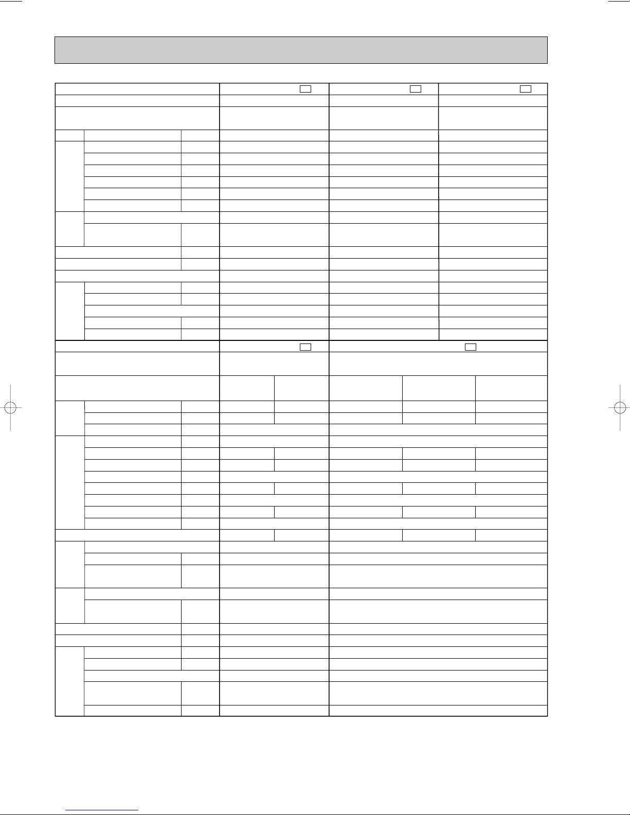
MXZ-A18WV -
E1
NOTE: Electrical data is for outdoor unit only.
07
09
12
07+07
07+09
07+12
09+09
09+12
12+12
90
90
90
90
90
90
90
90
90
4.73
5.14
6.76
9.32
9.37
9.03
9.28
8.91
8.55
3.3
(0.9-4.0)
3.6
(0.9-4.5)
4.0
(0.9-4.8)
6.1
(1.53-6.70)
6.2
(1.53-6.80)
6.5
(1.55-7.00)
6.5
(1.55-7.0)
6.55
(1.56-7.1)
6.6
(1.58-7.2)
0.980
(0.225-1.115)
1.065
(0.225-1.195)
1.400
(0.220-1.680)
1.930
(0.300-2.070)
1.940
(0.300-2.040)
1.870
(0.295-1.980)
1.920
(0.295-2.010)
1.845
(0.295-1.950)
1.770
(0.290-1.850)
–
–
–
3.05
3.23
3.88
3.25
3.77
3.30
3.3
3.6
4.0
3.05
2.97
2.62
3.25
2.78
3.30
Indoor units
combination
Unit A Unit B
Heating capacity (kW)
Total
Outdoor unit
power consumption
(kW)
Current
(A)
Power
factor
(%)
230V
MXZ-A18WV -
E1
OUTDOOR UNIT
MXZ-A18WV-
Combination of the
connectable indoor units
07+07
07+09
07+12
09+09
09+12
12+12
E1
❈There is no combination other than this table.
4
INDOOR UNITS COMBINATION
9
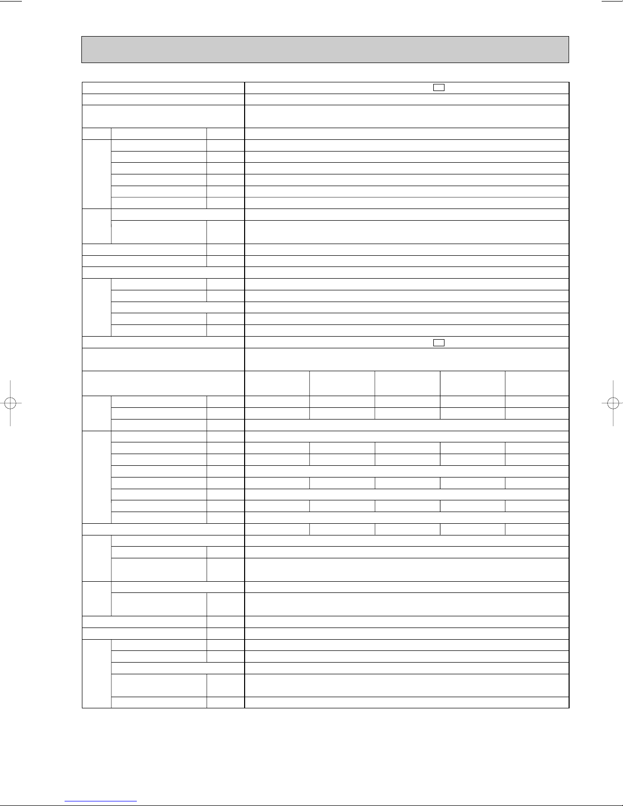
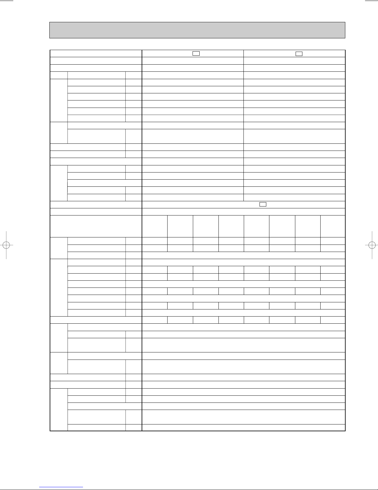
Page 10
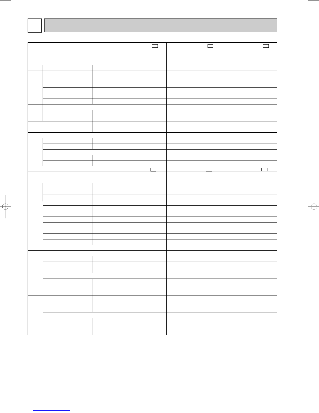
5
Indoor model
Function
Indoor unit power supply
Air flow(High/Med. /Low )
Power outlet
Running current
Power input
Power factor
Starting current
Fan motor current
Model
Winding
resistance(at 20:)
Dimensions WOHOD
Weight
Air direction
Sound level(High/Med. /Low )
Fan speed (High/Med. /Low )
Fan speed regulator
Thermistor RT11(at 25:)
Thermistor RT12(at 25:)
Outdoor model
Capacity
Dehumidification
Outdoor air flow
Power outlet
Running current
Power input
Auxiliary heater
Power factor
Starting current
Compressor motor current
Fan motor current
Model
Output
Winding
resistance(at 20:)
Model
Winding
resistance(at 20:)
Dimensions WOHOD
Weight
Sound level
Fan speed
Fan speed regulator
Refrigerant filling
capacity (R410A)
Refrigerating oil (Model)
K /h
A
A
W
%
A
A
"
mm
kg
dB
rpm
k"
k"
kW
R/h
K /h
A
A
W
A(kW)
%
A
A
A
W
"
"
mm
kg
dB
rpm
kg
cc
MSC-A07WV -
E1
Single phase
230V,50Hz
10
0.17
35
90
—
0.17
WHT-BLK 413
BLK-RED 334
815O278O217
9
5
3
10
10
MU-A07WV -
E1
Single phase
230V,50Hz
10
—
2.76
0.22
RN092VHSHT
600
C-R 3.87
C-S 6.14
RA6V23-FC
WHT-BLK 353
BLK-RED 321
780o540o255
34
45
735
1
0.75
350 (NEO22 )
Cooling
474/372 /276
RC4V19-LA
36/31 /25
900/750 /600
2.3
0.9
1,686
2.98
675
98
23
3.24
MSC-A09WV - E1
Single phase
230V,50Hz
10
0.17
35
RC4V19-LA
WHT-BLK 413
BLK-RED 334
815O278O217
9
5
3
10
10
MU-A09WV -
E1
Single phase
230V,50Hz
10
—
RN099VHSHT
700
C-R 3.40
C-S 4.56
RA6V23-FC
WHT-BLK 353
BLK-RED 321
780o540o255
34
45
735
1
0.80
350 (NEO22 )
Cooling
474/384 /306
90
—
0.17
36/31 /25
900/770 /650
2.55
1.1
1,686
3.26
745
99
24
3.04
0.22
3.27
MSC-A12WV - E1
Single phase
230V,50Hz
582/444 /324
10
0.19
40
RC4V19-KA
WHT-BLK 316
BLK-RED 299
815O278O217
10
5
3
10
10
MU-A12WV -
E1
Single phase
230V,50Hz
1.6
1,914
10
4.91
—
97
29
RN135VHSHT
900
C-R 2.79
C-S 3.36
RA6V33-DC
WHT-BLK 301
BLK-RED 332
780o540o255
36
49
825
1
0.83
620 (NEO22)
Cooling
92
—
0.19
40/33 /26
930/760 /600
3.45
1,100
4.60
0.31
3.03
Electrical
data
Fan
motor
Special
remarks
Compressor
Electrical
data
Fan
motor
Special
remarks
Capacity
Coefficient of performance(C.O.P)
Outdoor unit power supply
Capacity
ww
ww
w
w
w
w
w
w
w
w
w
w
ww
w
w
ww
ww
w
w
SPECIFICATION
NOTE: Test conditions are based on ISO 5151.
Cooling : Indoor DB27°C WB19°C
Outdoor DB35°C WB24°C
Indoor-Outdoor piping length 5m
w Reference value
10
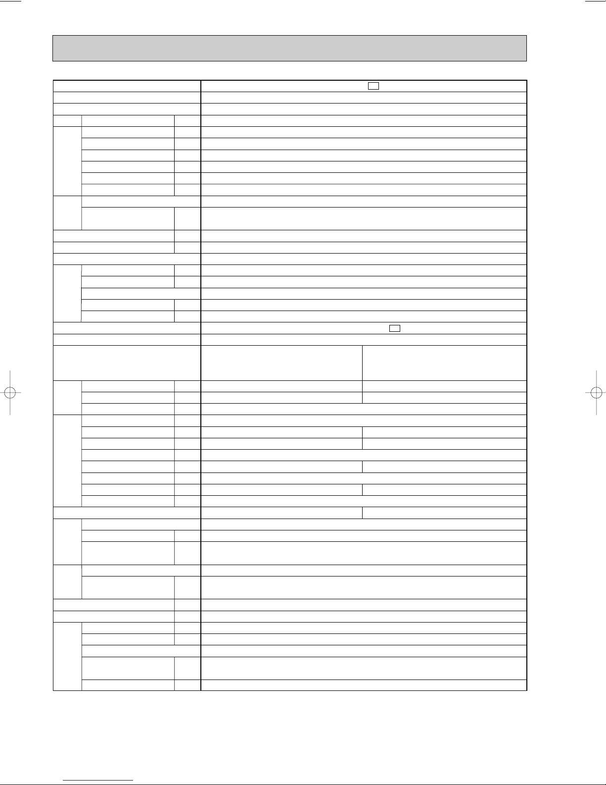
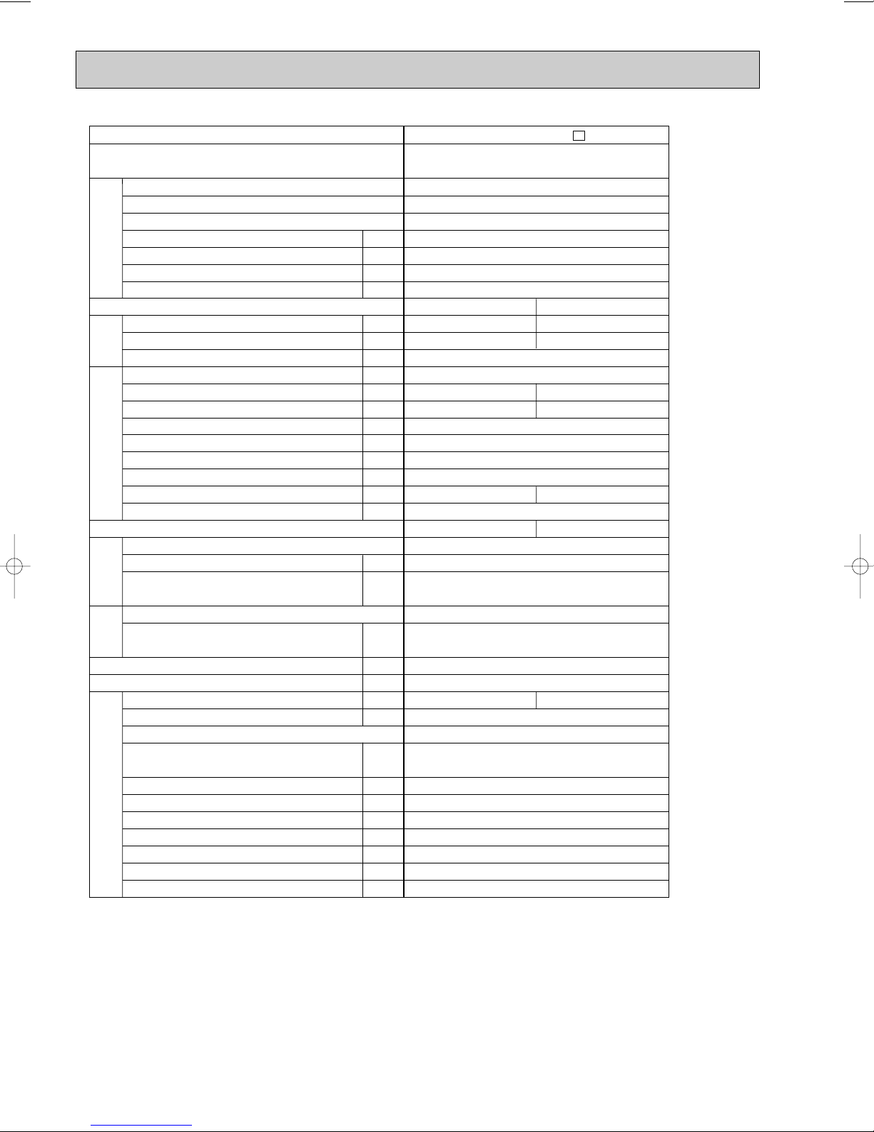
Page 11
Indoor model
Cooling
474/372 /276
Indoor unit power supply
Capacity
Air flow(High/Med. /Low )
Power outlet
Running current
Power input
Power factor
Electrical
data
Starting current
Fan motor current
Function
w
w
K /h
A
A
W
%
A
A
Model
Winding
Fan
motor
resistance(at 20:)
Dimensions WOHOD
Weight
"
mm
kg
Air direction
Sound level(High/Med. /Low )
Fan speed(High/Med. /Low )
ww
ww
dB
rpm
36/31 /25
900/750 /600
Fan speed regulator
Thermistor RT11(at 25:)
Special
remarks
Thermistor RT12(at 25:)
k"
k"
Outdoor model
Outdoor unit power supply
Capacity
Dehumidification
Outdoor air flow
Capacity
Power outlet
Running current
Power input
Auxiliary heater
Power factor
Electrical
data
Starting current
Compressor motor current
Fan motor current
kW
R/h
K /h
A
A
W
A(kW)
%
A
A
A
Coefficient of performance (C.O.P)
Model
Output
Winding
Compressor
resistance (at 20:)
Model
Winding
Fan
motor
resistance (at 20:)
Dimensions WOHOD
Weight
Sound level
Fan speed
W
"
"
mm
kg
dB
rpm
Fan speed regulator
Refrigerant filling
Special
remarks
capacity (R410A)
Refrigerating oil (Model)
Thermistor RT61 (at 0:)
kg
cc
k"
350 (NEO22)
NOTE: Test conditions are based on ISO 5151.
Cooling : Indoor DB27°C WB19°C Heating : Indoor DB20°C
Outdoor DB35°C WB24°C Outdoor DB 7°C/WB 6°C
Indoor-Outdoor piping length 5m
w Reference value
MSC-A07WV -
Heating
Single phase
230V,50Hz
w
w
510/420 /342
10
0.17
35
90
—
0.17
RC4V19-LA
WHT-BLK 413
BLK-RED 334
815O278O217
9
5
w
w
36/31 /25
w
w
950/820 /700
3
10
10
MUH-A07WV -
Single phase
230V,50Hz
2.3
2.5
0.9
1,686
10
2.98
675
2.86
655
—
98
100
23
2.76
2.64
0.22
3.24
3.62
RN092VHSHT
600
C-R 3.87
C-S 6.14
RA6V23-FB
WHT-BLK 353
BLK-RED 321
780o540o255
35
47
735
1
0.75
33.18
—
E1
w
w
w
E1
MSC-A09WV - E1
Cooling
Single phase
230V,50Hz
w
w
474/384 /306
RC4V19-LA
WHT-BLK 413
BLK-RED 334
815O278O217
w
w
w
36/31 /25
w
900/770 /650
MUH-A09WV -
Single phase
230V,50Hz
2.55
1.1
3.26
745
99
2.95
3.27
RN104VHSHT
RA6V33-DB
WHT-BLK 301
BLK-RED 332
780o540o255
350 (NEO22)
Heating
w
588/456 /342
10
0.17
35
90
—
0.17
9
5
w
39/32 /25
w
1,050/870 /700
3
10
10
1,710
10
—
24
0.31
700
C-R 3.40
C-S 4.56
38
49
825
1
1.10
33.18
3.05
—
3.52
805
99
3.21
3.69
w
w
w
E1
MSC-A12WV - E1
Cooling
Single phase
w
582/444 /324
RC4V19-KA
WHT-BLK 316
BLK-RED 299
815O278O217
w
w
w
40/33 /26
w
930/760 /600
MUH-A12WV -
Single phase
3.4
1.6
4.51
1,020
98
4.20
3.21
RN135VHSHT
RA6V33-DB
WHT-BLK 301
BLK-RED 332
780o540o255
620 (NEO22)
Heating
230V,50Hz
w
w
606/498 /396
10
0.19
40
92
—
0.19
10
5
w
39/33 /26
w
960/830 /700
3
10
10
230V,50Hz
1,710
10
—
29
0.31
900
C-R 2.79
C-S 3.36
40
49
825
1
1.15
33.18
w
w
w
E1
3.9
—
4.61
1,040
98
4.30
3.61
w
w
w
11
Page 12
Indoor model
Function
Indoor unit power supply
Air flow (High/Med./Low)
Power outlet
Running current
Power input
Power factor
Starting current
Fan motor current
Model
Winding
resistance(at 20:)
Dimensions WOHOD
Weight
Air direction
Sound level
(High/Med./Low)
Fan speed
(High/Med./Low)
Fan speed regulator
Thermistor RT11 (at 25:)
Thermistor RT12 (at 25:)
Outdoor model
Capacity
Dehumidification
Outdoor air flow
Power outlet
Running current
Power input
Auxiliary heater
Power factor
Starting current
Compressor motor current
Fan motor current
Model
Output
Winding
resistance (at 20:)
Model
Winding
resistance (at 20:)
Dimensions WOHOD
Weight
Sound level
Fan speed
Fan speed regulator
Refrigerant filling
capacity (R410A)
Refrigerating oil (Model)
K /h
A
A
W
%
A
A
"
mm
kg
dB
rpm
k"
k"
kW
R/h
K /h
A
A
W
A(kW)
%
A
A
A
W
"
"
mm
kg
dB
rpm
kg
cc
MSC-A07WV -
E1
Cooling
Single phase
230V,50Hz
474/372 /276
10
0.17
35
90
—
0.17
RC4V19-LA
WHT-BLK 413
BLK-RED 334
815O278O217
9
5
36/31 /25
900/750 /600
3
10
10
MUX-A10WV -
E1
Single phase
230V,50Hz
1,914
10
—
21
0.29
RN092VHSHT
600
C-R 3.87
C-S 6.14
RA6V33-FC
WHT-BLK 223
BLK-RED 221
780O540O255
35
49
825
1
0.90 (Room A+B)
350 (NEO22)
Single
A or B
2.4
0.9
3.20
725
98.5
2.91
3.16
Single
A
3.5
1.4
5.73
1,280
97.1
5.16
2.65
Double
A+B
3.5+2.4
1.4+0.9
8.96
2,005
97.3
8.39
2.84
Double
A+B
1.4O2
0.2O2
3.25
730
97.7
2.96
3.50
MSC-A07WV -
E1
Cooling
Single phase
230V,50Hz
474/372 /276
10
0.17
35
90
—
0.17
RC4V19-LA
WHT-BLK 413
BLK-RED 334
815O278O217
9
5
36/31 /25
900/750 /600
3
10
10
MUX-A19WV -
E1
Single phase
230V,50Hz
MSC-A12WV -
E1
Electrical
data
Fan
motor
Special
remarks
Compressor
Electrical
data
Fan
motor
Special
remarks
Capacity
Coefficient of performance (C.O.P)
Outdoor unit power supply
Indoor unit No.
Capacity
w
w
ww
w
w
Cooling
Single phase
230V,50Hz
582/444 /324
10
0.19
40
92
—
0.19
RC4V19-KA
WHT-BLK 316
BLK-RED 299
815O278O217
10
5
40/33 /26
930/760 /600
3
10
10
Single
B
2.4
0.9
2,460
20
3.51
785
—
97.2
48
2.94
0.57
2.93
MC1 : RN145VHSHT, MC2 : RN092VHSHT
MC1 : 1,000, MC2 : 600
RA6V60-GA
WHT-BLK 90
BLK-RED 146
840O640O330
66
52
730
1
1.00 (Room A)
0.80 (Room B)
MC1 : 620 (NEO22), MC2 : 350 (NEO22)
C-R 2.43
C-S 3.80
MC1 : , MC2 :
C-R 3.87
C-S 6.14
w
ww
w
w
ww
w
w
ww
ww
ww
w
ww
NOTE: Test conditions are based on ISO 5151.
Cooling : Indoor DB27°C WB19°C Heating : Indoor DB20°C
Indoor-Outdoor piping length 5m
w Reference value
Outdoor DB35°C WB24°C Outdoor DB 7°C/WB 6°C
12
Page 13
Indoor model
Function
Indoor unit power supply
w
K /h
A
A
W
%
A
A
Capacity
Air flow (High/Med./Low)
Power outlet
Running current
Power input
Power factor
Electrical
data
Starting current
Fan motor current
w
Model
Winding
Fan
motor
resistance (at 20:)
Dimensions WOHOD
Weight
Air direction
Sound level
Fan speed
Fan speed regulator
Special
remarks
Thermistor RT11 (at 25:)
(High/Med./Low)
Thermistor RT12 (at 25:)
w
(High/Med./Low)
ww
"
mm
kg
w
dB
rpm
k"
k"
Outdoor model
Outdoor unit power supply
Indoor unit No.
Capacity
Dehumidification
Outdoor air flow
Capacity
Power outlet
Running current
Power input
Auxiliary heater
Power factor
Electrical
data
Starting current
Compressor motor current
Fan motor current
kW
R/h
K /h
A
A
W
A(kW)
%
A
A
A
Coefficient of performance (C.O.P)
Model
Output
Winding
Compressor
resistance (at 20:)
Model
Winding
Fan
motor
resistance (at 20:)
Dimensions WOHOD
Weight
Sound level
Fan speed
W
"
"
mm
kg
dB
rpm
Fan speed regulator
Refrigerant filling
Special
remarks
capacity (R410A)
Refrigerating oil (Model)
kg
cc
NOTE: Test conditions are based on ISO 5151.
Cooling : Indoor DB27°C WB19°C Heating : Indoor DB20°C
Outdoor DB35°C WB24°C Outdoor DB 7°C/WB 6°C
Indoor-Outdoor piping length 5m
w Reference value
Single
A
2.6
0.9
3.64
815
97.3
3.07
3.06
E1
MSC-A09WV -
Cooling
Single phase
230V,50Hz
ww
474/384 /306
10
0.17
35
90
—
0.17
RC4V19-LA
WHT-BLK 413
BLK-RED 334
815O278O217
9
5
ww
36/31 /25
ww
900/770 /650
3
10
10
E1
MUX-A20WV -
Single phase
230V,50Hz
Single
B or C
2.9
1.2
Double
A+B or A+C
2.6+2.8
0.9+1.1
Double
B+C
1.75O2
0.3O2
2,460
20
4.86
1,075
8.18
1,850
4.86
1,090
—
96.2
98.3
97.5
47
4.29
7.61
4.29
0.57
2.61
2.81
3.02
MC1 : RN099VHSHT, MC2 : RN125VHSHT
MC1 : 650, MC2 : 800
C-R 3.40
MC1 : , MC2 :
C-S 4.56
C-R 2.86
C-S 5.72
RA6V60-GA
WHT-BLK 90
BLK-RED 146
840O640O330
65
52
730
1
0.80 (Room A)
1.00 (Room B+C)
MC1 : 350 (NEO22), MC2 : 350 (NEO22)
13
Triple
A+B+C
2.5+1.75O2
0.8+0.3O2
8.41
1,885
97.5
7.84
3.02
Page 14
Indoor model
Function
Indoor unit power supply
Air flow (High/Med./Low)
Power outlet
Running current
Power input
Power factor
Starting current
Fan motor current
Model
Winding
resistance(at20:)
Dimensions WOHOD
Weight
Air direction
Sound level
(High/Med./Low)
Fan speed
(High/Med./Low)
Fan speed regulator
Thermistor RT11 (at 25:)
Thermistor RT12 (at 25:)
Outdoor model
Capacity
Dehumidification
Outdoor air flow
Power outlet
Running current
Power input
Auxiliary heater
Power factor
Starting current
Compressor motor current
Fan motor current
Model
Output
Winding
resistance (at 20:)
Model
Winding
resistance (at 20:)
Dimensions WOHOD
Weight
Sound level
Fan speed
Fan speed regulator
Refrigerant filling
capacity (R410A)
Refrigerating oil (Model)
K /h
A
A
W
%
A
A
"
mm
kg
dB
rpm
k"
k"
kW
R/h
K /h
A
A
W
A(kW)
%
A
A
A
W
"
"
mm
kg
dB
rpm
kg
cc
MSC-A12WV -
E1
(Unit A ,B)
Cooling
Single phase 230V,50Hz
582/444 /324
10
0.19
40
92
—
0.19
RC4V19-KA
WHT-BLK 316
BLK-RED 299
815O278O217
10
5
40/33 /26
930/760 /600
3
10
10
Electrical
data
Fan
motor
Special
remarks
Compressor
Electrical
data
Fan
motor
Special
remarks
Capacity
Coefficient of performance (C.O.P)
Outdoor unit power supply
Indoor unit No.
Capacity
MUX-A25WV -
E1
Single phase 230V,50Hz
2,460
20
—
54
0.57
MC1 : RN145VHSHT, MC2 : RN145VHSHT
MC1 : 1,000, MC2 : 1,000
RA6V60-GA
WHT-BLK 90
BLK-RED 146
840O640O330
68
52
730
1
0.95 (Room A)
0.95 (Room B)
MC1 : 620 (NEO22), MC2 : 620 (NEO22)
w
ww
w
ww
ww
Single
A or B
3.5
1.4
5.88
1,300
96.1
5.31
2.61
Double
A+B
3.5O2
1.4O2
11.49
2,540
96.1
10.92
2.67
C-R 2.43
C-S 3.80
MC1 : , MC2 :
C-R 2.43
C-S 3.80
w
ww
NOTE: Test conditions are based on ISO 5151.
Cooling : Indoor DB27°C WB19°C Heating : Indoor DB20°C
Indoor-Outdoor piping length 5m
w Reference value
Outdoor DB35°C WB24°C Outdoor DB 7°C/WB 6°C
14
Page 15
Indoor model
MSC-A09WV -
Function
Indoor unit power supply
Capacity
Air flow (High/Med./Low)
Power outlet
Running current
Power input
Power factor
Electrical
data
Starting current
Fan motor current
w
K /h
A
A
W
%
A
A
Model
Winding
Fan
motor
resistance (at 20:)
Dimensions WOHOD
Weight
Air direction
Sound level
Fan speed
Fan speed regulator
Special
remarks
Thermistor RT11 (at 25:)
(High/Med./Low)
Thermistor RT12 (at 25:)
w
(High/Med./Low)
ww
"
mm
kg
w
dB
rpm
k"
k"
Outdoor model
Outdoor unit power supply
Single
Indoor unit No.
Capacity
Dehumidification
Outdoor air flow
Capacity
Power outlet
Running current
Power input
Auxiliary heater
Power factor
Electrical
data
Starting current
Compressor motor current
Fan motor current
Coefficient of performance (C.O.P)
R/h
K /h
A(kW)
kW
A
A
W
%
A
A
A
A or B
3.4
1.2
5.28
1,180
97.2
4.75
2.79
Model
Output
Winding
Compressor
resistance (at 20:)
Model
Winding
Fan
motor
resistance (at 20:)
Dimensions WOHOD
Weight
Sound level
Fan speed
W
"
"
mm
kg
dB
rpm
Fan speed regulator
Refrigerant filling
Special
remarks
capacity (R410A)
Refrigerating oil (Model)
NOTE: Test conditions are based on ISO 5151.
Cooling : Indoor DB27°C WB19°C Heating : Indoor DB20°C
kg
cc
Outdoor DB35°C WB24°C Outdoor DB 7°C/WB 6°C
Indoor-Outdoor piping length 5m
w Reference value
E1
(Unit C ,D)
Cooling
Single phase 230V,50Hz
474/384 /306
ww
10
0.17
35
90
—
0.17
RC4V19-LA
WHT-BLK 413
BLK-RED 334
815O278O217
9
5
ww
36/31 /25
900/770 /650
ww
3
10
10
Single phase 230V,50Hz
Single
C or D
2.75
1.1
4.54
1,015
97.2
4.01
2.62
Double
A+B
1.95O2
0.2O2
5.46
1,210
96.4
4.93
3.02
MC1 : RN145VHSHT, MC2 : RN125VHSHT
MC1 : , MC2 :
MC1 : 620 (NEO22), MC2 : 350 (NEO22)
15
MSC-A12WV -
Single phase 230V,50Hz
MUX-A26WV -
Double
A+C or A+D
or
B+C or B+D
3.4+2.7
1.2+1.1
E1
Double
C+D
1.7O2
0.3O2
2,760
20
9.57
2,095
4.78
1,060
—
95.2
96.4
52
9.04
4.25
0.53
2.81
3.01
MC1 : 1,000, MC2 : 800
C-R 2.43
C-S 3.80
C-R 2.86
C-S 5.72
RA6V60-FA
WHT-BLK 79
BLK-RED 80
840O850O330
76
52
730
1
1.05 (Room A+B)
1.05 (Room C+D)
582/444 /324
RC4V19-KA
WHT-BLK 316
BLK-RED 299
815O278O217
930/760 /600
Triple
A+B+C
or
A+B+D
1.95O2+2.8
0.2O2+1.1
9.61
2,105
95.2
9.08
3.02
E1
Cooling
w
10
0.19
40
92
—
0.19
10
5
ww
40/33 /26
w
3
10
10
3.4+1.7O2
1.2+0.3O2
(Unit A ,B)
w
w
Triple
A+C+D
or
B+C+D
A+B+C+D
1.95O2+1.7O2
0.2O2+0.3O2
9.66
2,140
96.3
9.13
3.02
Four
9.75
2,210
98.6
9.22
3.09
Page 16
Outdoor model
Indoor units number
Indoor units total capacity (Connectable)
indoor units total capacity (Simultaneous operation)
Piping total length
Connecting pipe length
Height difference (Indoor ~ Outdoor)
Height difference (Indoor ~ Indoor)
Function
Capacity
Dehumidification
Outdoor air flow
Power outlet
Running current
Power input
Auxiliary heater
Crankcase heater
Power factor
Starting current
Compressor motor current
Fan motor current
Model
Output
Winding
resistance (at 20:)
Model
Winding
resistance (at 20:)
Dimensions WOHOD
Weight
Sound level (Hi)
Fan speed (Hi)
Fan speed regulator
Refrigerant filling
capacity (R410A)
Refrigerating oil (Model)
Thermistor RT61
Thermistor RT62
Thermistor RT63
Thermistor RT6A,6B
Thermistor RT65
Thermistor RT68
m
m
m
m
kW
R/h
K /h
A
A
W
A(kW)
W
%
A
A
A
W
"
"
mm
kg
dB
rpm
kg
cc
k"
k"
k"
k"
k"
k"
Compressor
Electrical
data
Fan
motor
Special
remarks
Capacity System
Coefficient of performance (C.O.P)
Outdoor unit power supply
MXZ-A18WV -
E1
Single phase
230V,50Hz
2
Total model name 24
Total model name 24
Max. 30 (chargeless 20)
Max. 20
10
10
2,460
20
—
—
90.0
8.98
0.57
SNV-092FJYH (ROTARY)
1,450
U-V 2.56
V-W 2.56 W-U 2.56
RA6V49-AA
WHT-BLK 139.9 BLK-YLW 34.2
BLK-RED 205.3
840(+69)o640o330
52
725
2
1.75
450 (NE022)
13.4 (at 100:)
10.0 (at 25:)
10.0 (at 25:)
10.0 (at 25:)
17.0 (at 50:)
10.0 (at 25:)
Cooling
5.4 (1.55~6.0)
—
8.98
1,860 (370~2,130)
8.41
2.90
49
Heating
6.6 (1.58~7.2)
—
8.55
1,770 (290~1,850)
7.98
3.73
50
NOTE: Test conditions are based on ISO 5151 (Refrigerant piping length (one way) :5m
✽1 Electrical data is for only outdoor unit.
TEST CONDITIONS COOLING INDOOR DB27.0°C WB19.0°C
OUTDOOR DB35.0°C WB24.0°C
HEATING INDOOR DB20.0°C
OUTDOOR DB 7.0°C WB 6.0°C
16
Page 17
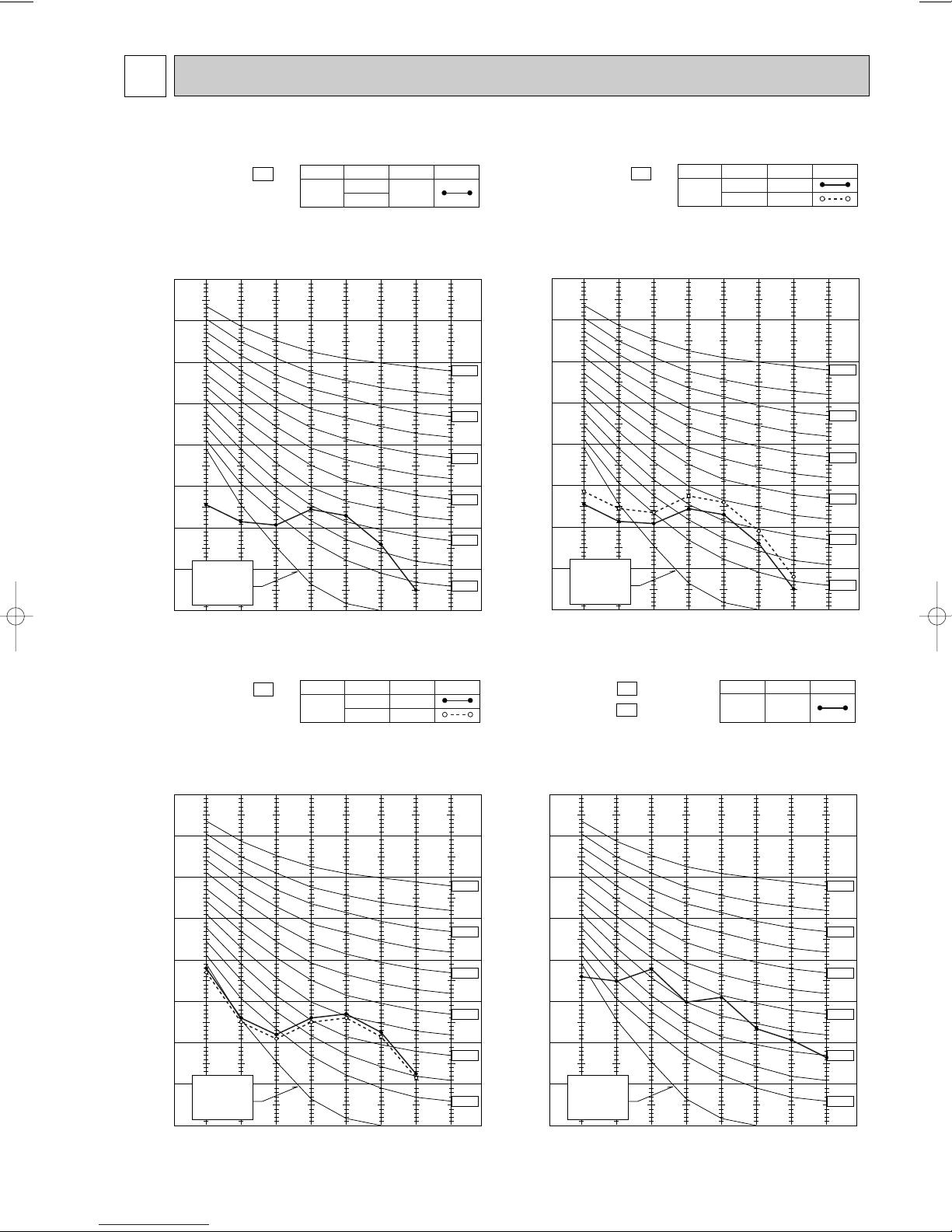
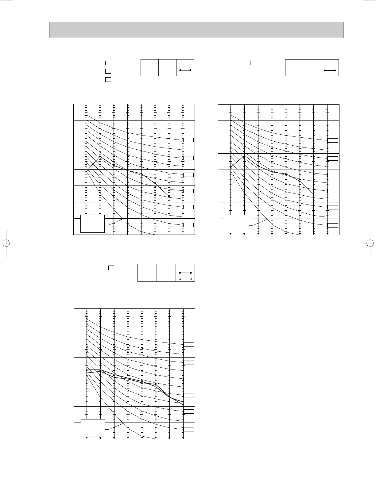
NOISE CRITERIA CURVES6
90
80
70
60
50
40
30
20
10
63 125 250 500 1000 2000 4000 8000
APPROXIMATE
TERESHOLD OF
HEARING FOR
CONTINUOUS
NOISE
NC-60
NC-50
NC-40
NC-30
NC-20
NC-70
OCTAVE BAND SOUND PRESSURE LEVEL, dB re 0.0002 MICRO BAR
BAND CENTER FREQUENCIES, Hz
Test conditions,
Cooling : DB27: WB19:
Heating : DB20: WB -:
MSC-A07WV- E1
COOL
High
FUNCTIONFAN SPEED
36
HEAT
SPL(dB
(A)) LINE
90
80
70
60
50
40
30
20
10
63 125 250 500 1000 2000 4000 8000
APPROXIMATE
TERESHOLD OF
HEARING FOR
CONTINUOUS
NOISE
NC-60
NC-50
NC-40
NC-30
NC-20
NC-70
OCTAVE BAND SOUND PRESSURE LEVEL, dB re 0.0002 MICRO BAR
BAND CENTER FREQUENCIES, Hz
Test conditions.
Cooling : DB27: WB19:
Heating : DB20: WB -:
MSC-A09WV- E1
COOL
High
FUNCTIONFAN SPEED
36
HEAT 39
SPL(dB
(A)) LINE
90
80
70
60
50
40
30
20
10
63 125 250 500 1000 2000 4000 8000
APPROXIMATE
TERESHOLD OF
HEARING FOR
CONTINUOUS
NOISE
NC-60
NC-50
NC-40
NC-30
NC-20
NC-70
OCTAVE BAND SOUND PRESSURE LEVEL, dB re 0.0002 MICRO BAR
BAND CENTER FREQUENCIES, Hz
Test conditions,
Cooling : DB27: WB19:
MSC-A12WV- E1
COOL
FUNCTIONFAN SPEED
40
HEAT
High
39
SPL(dB
(A)) LINE
90
80
70
60
50
40
30
20
10
63 125 250 500 1000 2000 4000 8000
APPROXIMATE
TERESHOLD OF
HEARING FOR
CONTINUOUS
NOISE
NC-60
NC-50
NC-40
NC-30
NC-20
NC-70
OCTAVE BAND SOUND PRESSURE LEVEL, dB re 0.0002 MICRO BAR
BAND CENTER FREQUENCIES, Hz
Test conditions,
Cooling : DB27: WB19:
MU-A07WV- E1
MU-A09WV- E1
COOL
FUNCTION
45
SPL(dB(A)) LINE
17
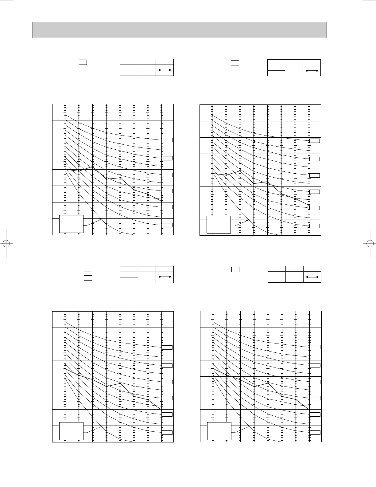
Page 18
90
80
70
60
50
40
30
20
10
63 125 250 500 1000 2000 4000 8000
APPROXIMATE
TERESHOLD OF
HEARING FOR
CONTINUOUS
NOISE
NC-60
NC-50
NC-40
NC-30
NC-20
NC-70
OCTAVE BAND SOUND PRESSURE LEVEL, dB re 0.0002 MICRO BAR
BAND CENTER FREQUENCIES, Hz
Test conditions,
Cooling :DB35: WB24:
Heating :DB 7: WB 6:
MUH-A09WV- E1
MUH-A12WV- E1
COOL
FUNCTION
49
HEAT
SPL(dB
(A)) LINE
90
80
70
60
50
40
30
20
10
63 125 250 500 1000 2000 4000 8000
APPROXIMATE
TERESHOLD OF
HEARING FOR
CONTINUOUS
NOISE
NC-60
NC-50
NC-40
NC-30
NC-20
NC-70
OCTAVE BAND SOUND PRESSURE LEVEL, dB re 0.0002 MICRO BAR
BAND CENTER FREQUENCIES, Hz
Test conditions.
Cooling : DB27: WB19:
MUX-A10WV- E1
COOL
FUNCTION
49
SPL(dB(A)) LINE
90
80
70
60
50
40
30
20
10
63 125 250 500 1000 2000 4000 8000
APPROXIMATE
TERESHOLD OF
HEARING FOR
CONTINUOUS
NOISE
NC-60
NC-50
NC-40
NC-30
NC-20
NC-70
OCTAVE BAND SOUND PRESSURE LEVEL, dB re 0.0002 MICRO BAR
BAND CENTER FREQUENCIES, Hz
Test conditions,
Cooling :DB35: WB24:
Heating :DB 7: WB 6:
MUH-A07WV- E1
COOL
FUNCTION
47
HEAT
SPL(dB
(A)) LINE
90
80
70
60
50
40
30
20
10
63 125 250 500 1000 2000 4000 8000
APPROXIMATE
TERESHOLD OF
HEARING FOR
CONTINUOUS
NOISE
NC-60
NC-50
NC-40
NC-30
NC-20
NC-70
OCTAVE BAND SOUND PRESSURE LEVEL, dB re 0.0002 MICRO BAR
BAND CENTER FREQUENCIES, Hz
Test conditions,
Cooling :DB35: WB24:
MU-A12WV- E1
COOL
FUNCTION
49
SPL(dB(A)) LINE
18
Page 19
MUX-A19WV - E1
MUX-A20WV - E1
MUX-A25WV - E1
FUNCTION
COOL
SPL(dB(A)) LINE
52
MUX-A26WV - E1
FUNCTION
COOL
SPL(dB(A)) LINE
52
Test conditions.
90
Cooling :DB35: WB24:
80
70
60
50
40
30
OCTAVE BAND SOUND PRESSURE LEVEL, dB re 0.0002 MICRO BAR
MXZ-A18WV - E1
APPROXIMATE
20
TERESHOLD OF
HEARING FOR
CONTINUOUS
NOISE
10
63 125 250 500 1000 2000 4000 8000
BAND CENTER FREQUENCIES, Hz
NOTCH
Cooling
Heating
SPL(dB(A))50LINE
49
NC-70
NC-60
NC-50
NC-40
NC-30
NC-20
Test conditions.
90
Cooling :DB35: WB24:
80
70
60
50
40
30
OCTAVE BAND SOUND PRESSURE LEVEL, dB re 0.0002 MICRO BAR
APPROXIMATE
20
TERESHOLD OF
HEARING FOR
CONTINUOUS
NOISE
10
63 125 250 500 1000 2000 4000 8000
BAND CENTER FREQUENCIES, Hz
NC-70
NC-60
NC-50
NC-40
NC-30
NC-20
Test conditions.
Cooling :DB 35: WB 24:
90
Heating :DB 7: WB 6:
80
70
60
50
40
30
OCTAVE BAND SOUND PRESSURE LEVEL, 0dB = 0.0002 MICRO BAR
APPROXIMATE
20
TERESHOLD OF
HEARING FOR
CONTINUOUS
NOISE
10
63 125 250 500 1000 2000 4000 8000
BAND CENTER FREQUENCIES, Hz
NC-70
NC-60
NC-50
NC-40
NC-30
NC-20
19
Page 20

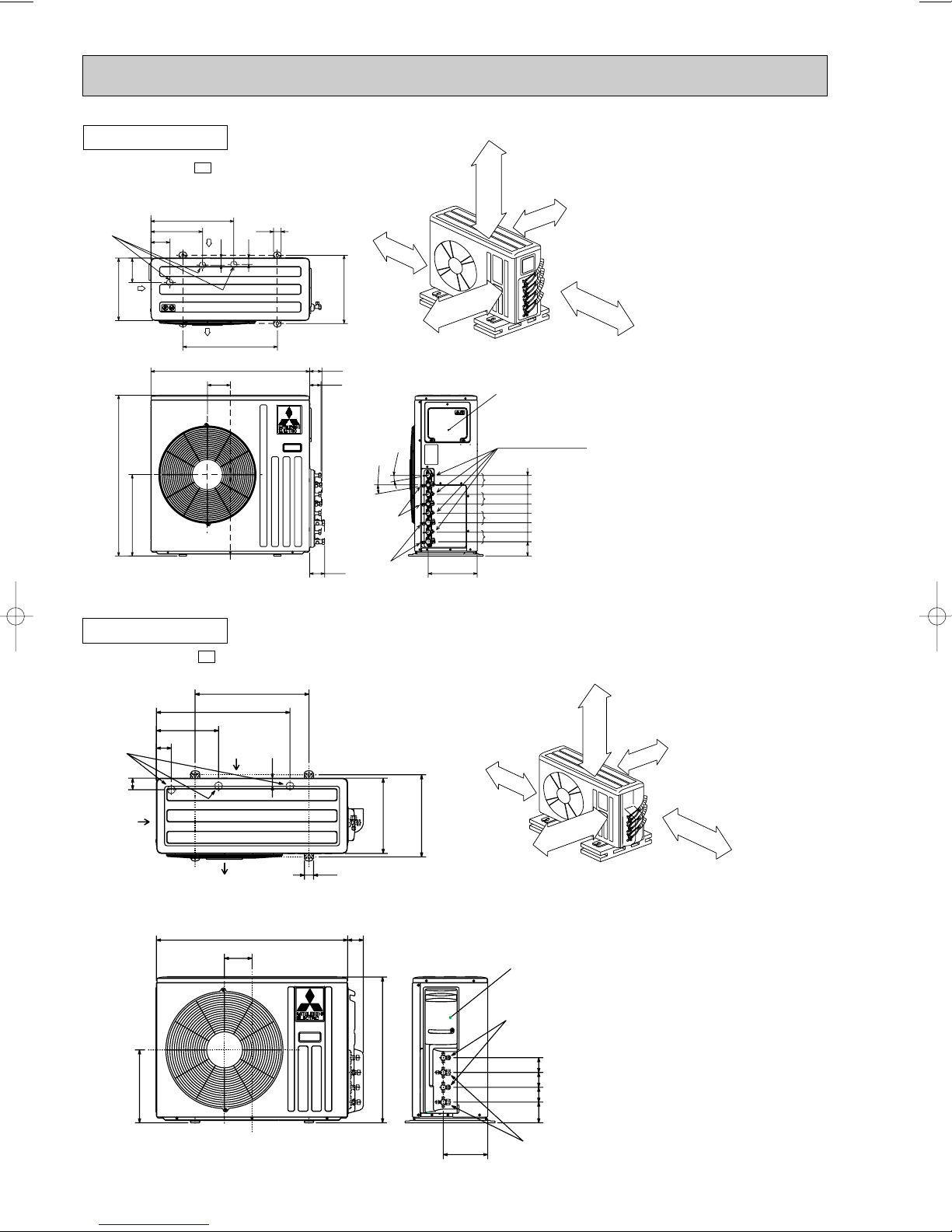
7
OUTLINES AND DIMENSIONS
MSC-A07WV MSC-A09WV -
INDOOR UNIT
Unit: mm
E1
E1
Installation plate
81.5
133.5
4.5
783
815
278
60
58
162
Wireless remote controller
606
Indoor unit
19
41
81.5
Air in
149
Power supply cord
Lead to right 1.0m
Lead to left 0.3m
7 or more
30
Air out
215
217
326326
5
Installation plate
Liquid line
Gas line
{
Insulation
90
110
Drain hose
(Connected part O,D)
Insulation
231.5
42
2.5
81.5
Wall hole
[9.52-0.43m
[37 O.D
[16
[28
271
[65
[6.35-0.5m
[21 I.D
MSC-A12WV -
INDOOR UNIT
278
60
58
162
E1
783
815
606
161.5
Installation plate
Indoor unit
149
19
Power supply cord
Lead to right 1.0m
Lead to left 0.3m
41
Air in
7 or more
30
Air out
215
217
326326
5
Installation plate
90
110
161.5
17.5
258
218.5
42
2.5
81.581.5
Wall hole
Liquid line
Gas line
{
Insulation
Drain hose
(Connected part O,D)
Insulation
[65
[6.35-0.5m
[9.52-0.43m
[37 O.D
[21 I.D
[16
[28
Wireless remote controller
20
Page 21
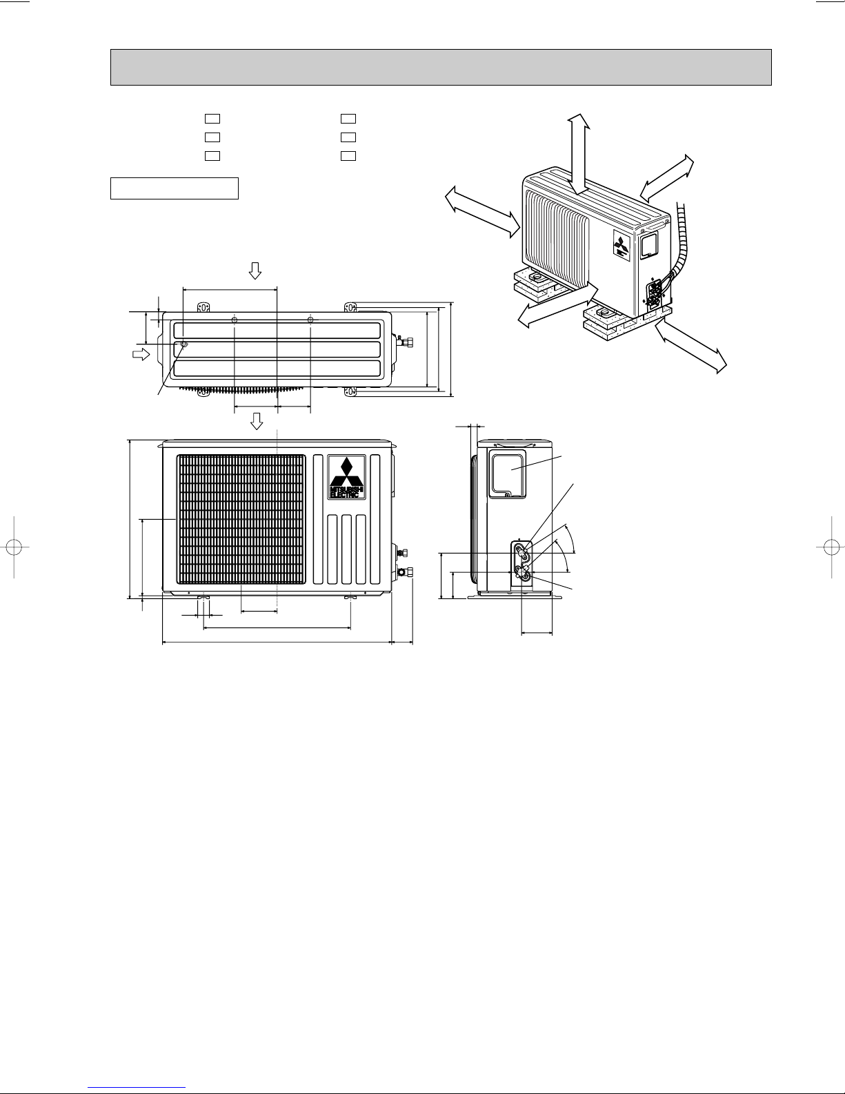
MU-A07WV - MUH-A07WV MU-A09WV - MUH-A09WV MU-A12WV - MUH-A12WV -
Unit: mm
E1E1
E1E1
E1E1
REQUIRED SPACE
OUTDOOR UNIT
320
32
109
Air in
Drainage
3holes [33
540
260
10
40
Air in
147
122
110
Air out
500
780
74
100mm or more
320
285
255
25
155
90
100mm or more
400mm or more
Service panel
Liquid refrigerant
pipe joint
Refrigerant pipe
(flared) [6.35
35-
43-
Gas refrigerant
pipe joint
104
Refrigerant pipe
(flared) [9.52 (MU-A07/A09WV
[12.7 (MU-A12WV
(MUH-A12WV
100mm or more
350mm or more
(MUH-A07/A09WV
)
)
)
)
21
Page 22
320
25
10-
126
76
120
56
260
10
780
500
122
40
540
320
285
255
Service panel
Gas refrigerant
pipe joint
Refrigerant pipe
(flared) [9.52
Liquid refrigerant
pipe joint
Refrigerant pipe
(flared) [6.35
Air out
Air in
Air in
176
226
109
32
110
147
Drainage
3holes [33
100mm or more
100mm or more
100mm or more
350mm or more
REQUIRED SPACE
400mm or more
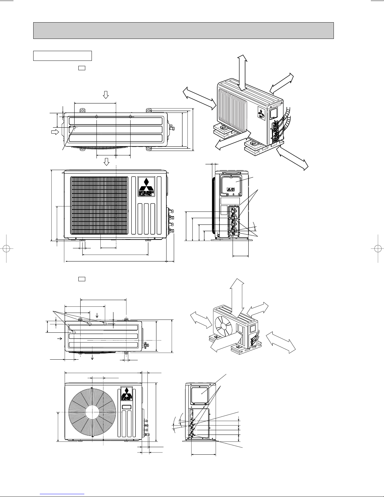
OUTDOOR UNIT
500
840 61
264
10°
10°
Service panel
Open as a rule
500mm or more if
the front and both
sides are open
100mm or more
200mm or more if
there are obstacles
to both sides
Open as a rule
500mm or more if the back,
both sides and top are open
350mm or more
100mm or more
B UNIT
A UNIT
Gas refrigerant
pipe joint
Refrigerant pipe
(flared) {9.52
Gas refrigerant
pipe joint
Refrigerant pipe
(flared) {12.7
Liquid refrigerant
pipe joint
Refrigerant pipe
(flared) {6.35
65
80
121
40
438
Air in
Air out
Air in
273
100
125
320
30
330
640
360
76
505050
Drainage
3holes {33
}
}
34
Unit: mm
MUX-A10WV-
E1
MUX-A19WV-
E1
22
Page 23
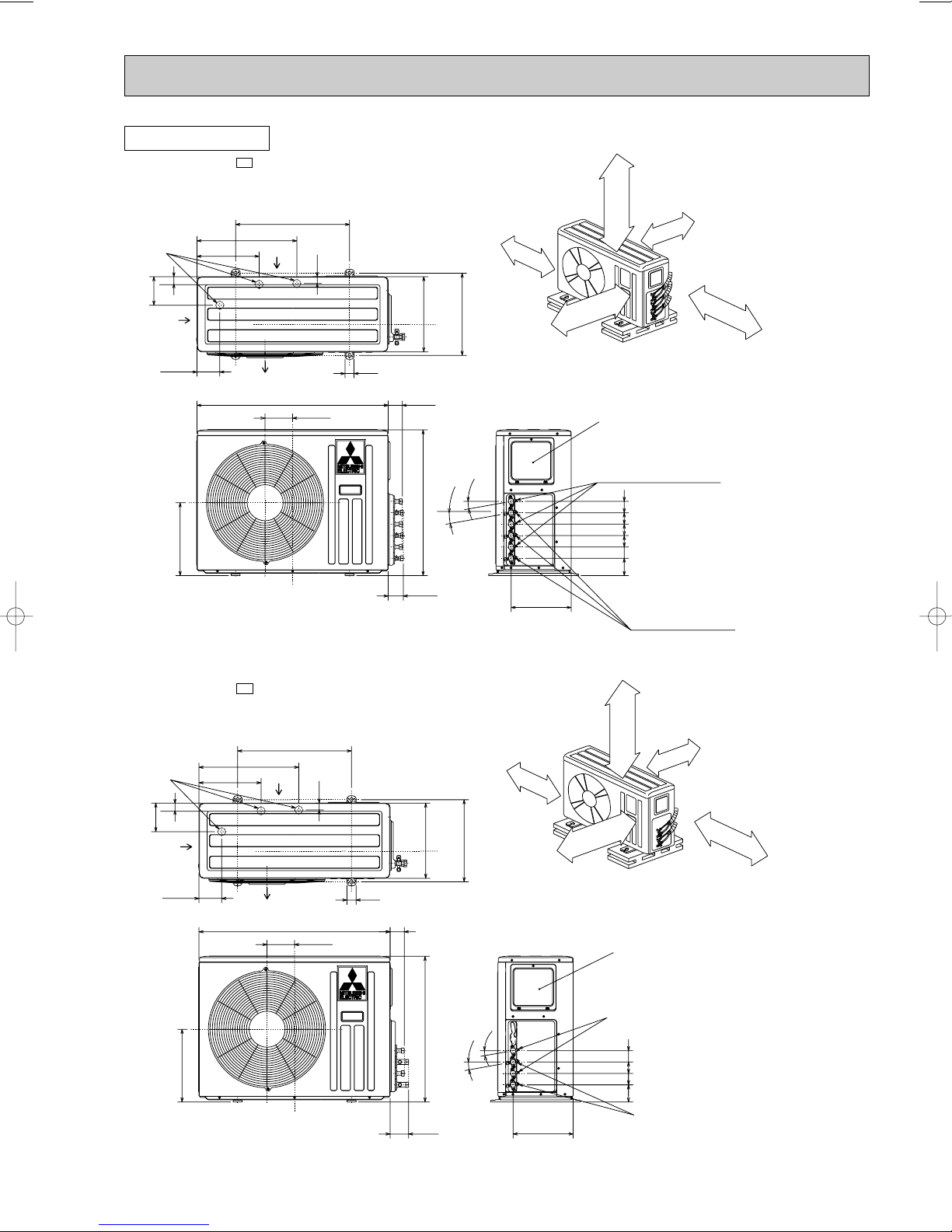
OUTDOOR UNIT
MUX-A20WV-
Drainage
3holes {33
34
125
Air in
100
320
E1
273
500
438
Air in
30
Air out
840 61
121
Unit: mm
Open as a rule
500mm or more if
the front and both
sides are open
100mm or more
100mm or more
330
360
Open as a rule
500mm or more if the back,
40
640
65
both sides and top are open
10°
10°
264
Service panel
Liquid refrigerant
pipe joint
Refrigerant pipe
(flared) {6.35
C UNIT
}
B UNIT
}
A UNIT
}
5050505050
76
Gas refrigerant
pipe joint
Refrigerant pipe
(flared) {9.52
200mm or more if
there are obstacles
to both sides
350mm or more
MUX-A25WV-
Drainage
3holes {33
125
Air in
273
34
100
320
E1
500
438
Air in
30
Air out
840 61
121
330
40
640
80
100mm or more
360
Open as a rule
500mm or more if the back,
both sides and top are open
10°
10°
264
}
}
B UNIT
A UNIT
Open as a rule
500mm or more if
the front and both
sides are open
Service panel
Liquid refrigerant
pipe joint
Refrigerant pipe
(flared) {6.35
505050
76
Gas refrigerant
pipe joint
Refrigerant pipe
(flared) {12.7
100mm or more
200mm or more if
there are obstacles
to both sides
350mm or more
23
Page 24
Service panel
D Unit
C Unit
B Unit
A Unit
{33
Drainage
3 holes
Air out
Air in
Air in
125
330
500
100
273
438
40
30
360
34
430
850
840
121
80
61
65
76
50
50
50
5050
50
50
260
10°
10°
Liquid refrigerant
pipe joint
Refrigerant pipe
(flared) {6.35
Gas refrigerant
pipe joint
Refrigerant pipe
(flared) {9.52
Gas refrigerant
pipe joint
Refrigerant pipe
(flared) {12.7
Open as a rule
500mm or more if
the front and both
sides are open
100mm or more
200mm or more if
there are obstacles
to both sides
Open as a rule
500mm or more if the back,
both sides and top are open
350mm or more
100mm or more
OUTDOOR UNIT
Unit: mm
MUX-A26WV-
E1
OUTDOOR UNIT
MXZ-A18WV -
Drainage
3 holes
([33)
50
Air in
320
E1
500
587
273
65
Air in
Air out
840
121
34
REQUIRED SPACE
More than
330
360
40
69
640
100mm
Open as a rule
More than 200mm if the back,
both sides and top are open
Note:
*
The dimensions given along the arrrows above are required to guarantee
the air conditioner's performance. Install the unit in as wide a place as
possible for later service or repairs.
Service panel
Liquid refrigerant valve
(flared [6.35)
B UNIT
}
195
}
A UNIT
90 65 65 65
Gas refrigerant valve
(flared [9.52)
24
Open as a rule
More than100mm
if the front and both
sides are open
*
More than 100mm
200mm or more if
there are obstacles
to both sides
More than 350mm
Page 25
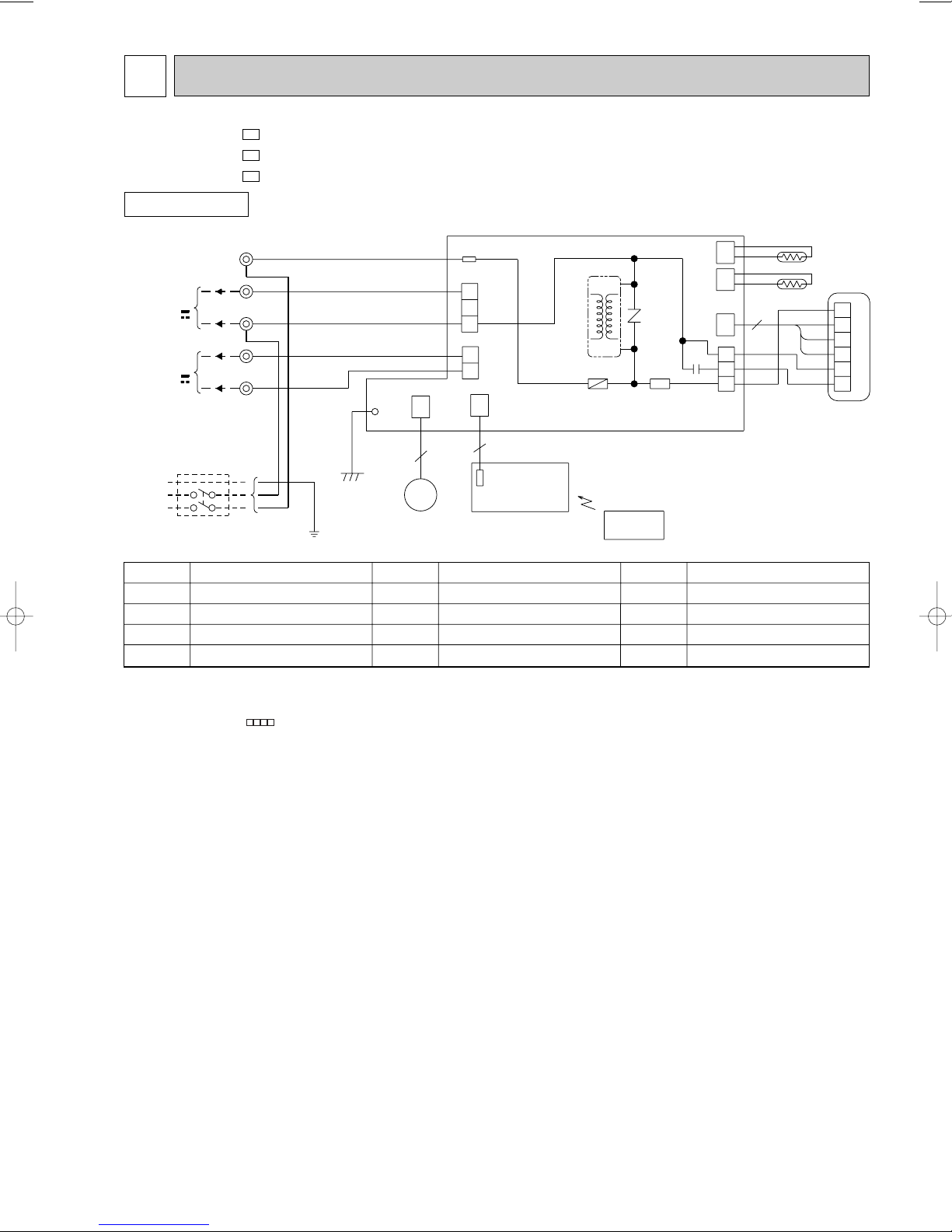
8
SYMBOL
NR11
RT11
RT12
SR141
NAME
NAME NAME
INDOOR FAN CAPACITOR
FUSE(3.15A)
INDOOR FAN MOTOR (INNER FUSE)
VANE MOTOR
VARISTOR
ROOM TEMPERATURE THERMIST OR
INDOOR COIL THERMISTOR
SOLID STATE RELAY
TERMINAL BLOCK
SYMBOL
C11
F11
MF
MV
SYMBOL
TB
T11
TRANSFORMER
CIRCUIT BREAKER
SR141
C11
RED
WHT
3
6
5
BRN
YLW
GRY
BLK
4
3
2
1
MF
121
CN
1
3
5
111
CN
112
CN
RT12
RT11
NR11
F11
ELECTRONIC CONTROL P.C. BOARD
CN211
TAB12
CN201
3
2
1
CN202
2
1
151
CN
5
5
BRN
RED
BLU
WHT
BLK
BLU
BRN
TB
L
3
N
2
1
12V
TO OUTDOOR
UNIT
CONNECTING
POWER
SUPPLY
CORD
~/N 230V
50Hz
GRN/YLW
POWER MONITOR,
RECEIVER
P.C.BOARD
REMOTE
CONTROLLER
MV
FOR
MUH OR
MXZ TYPE
FOR
MU OR
MUX TYPE
12V
PE
101
CN
T11
GRN
LD103
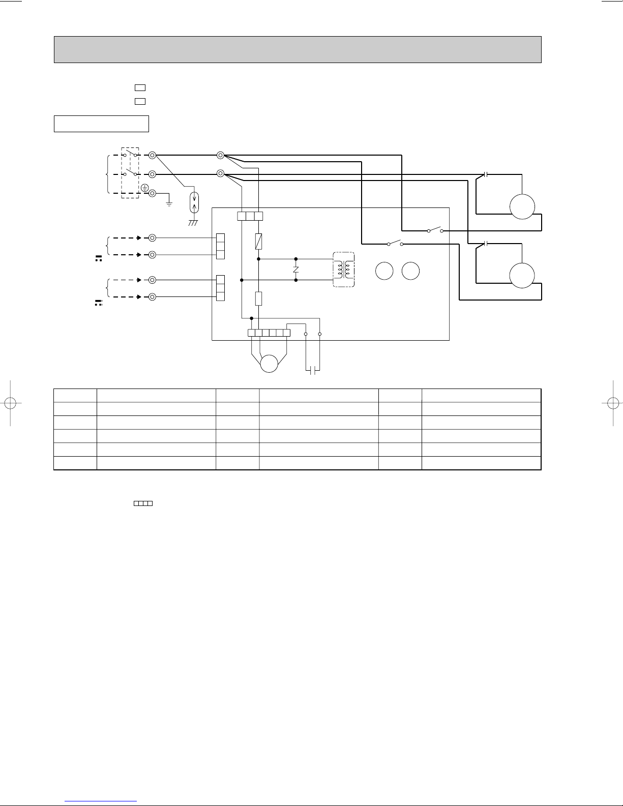
WIRING DIAGRAM
MSC-A07WV MSC-A09WV MSC-A12WV -
INDOOR UNIT
E1
E1
E1
MODELS WIRING DIAGRAM
NOTE:1. About the outdoor side electric wiring refer to the outdoor unit electric wiring diagram for servicing.
2. Use copper conductors only. (For field wiring)
3. Symbols below indicate.
/: Terminal block, : Connector
25
SG79J617H01
Page 26
SYMBOL
TB1,TB2
21S4
52C
SYMBOL
MF
NR61
RT61
SR61,SR62
T61
SYMBOL
C1
C65
DSAR
F61
MC
NAME
NAME NAME
COMPRESSOR CAPACITOR
OUTDOOR FAN CAPACITOR
SURGE ABSORBER
FUSE(2A)
COMPRESSOR(INNER PROTECTOR)
OUTDOOR FAN MOTOR(INNER FUSE)
VARISTOR
DEFROST THERMISTOR
SOLID STATE RELAY
TRANS FORMER
TERMINAL BLOCK
R.V. COIL
COMPRESSOR CONTACTOR
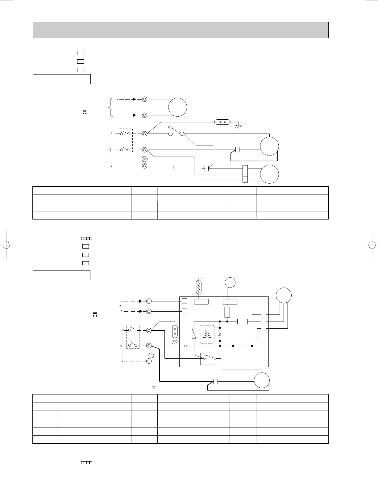
MU-A07WV -
MC
CN661
3
1
2
CN721
21S4
MF
SR62
SR61
TAB20
GRN/YLW
BLU
CIRCUIT BREAKER
POWER SUPPLY
BLU
BRN
DSAR
BLK
BRN
RED
DEICER P.C.BOARD
4
C1
BLK
RED
3
WHT
S
C
R
CN730
RT61
BLK
2
3
1
RED
WHT
12V
FROM
CONNECTING
INDOOR UNIT
TB2
3
N
TB1
L
N
PE
~/N
NR61
F61
T61
C65
CN711
52C
230V
50Hz
R.V.coil
heating ON
cooling OFF
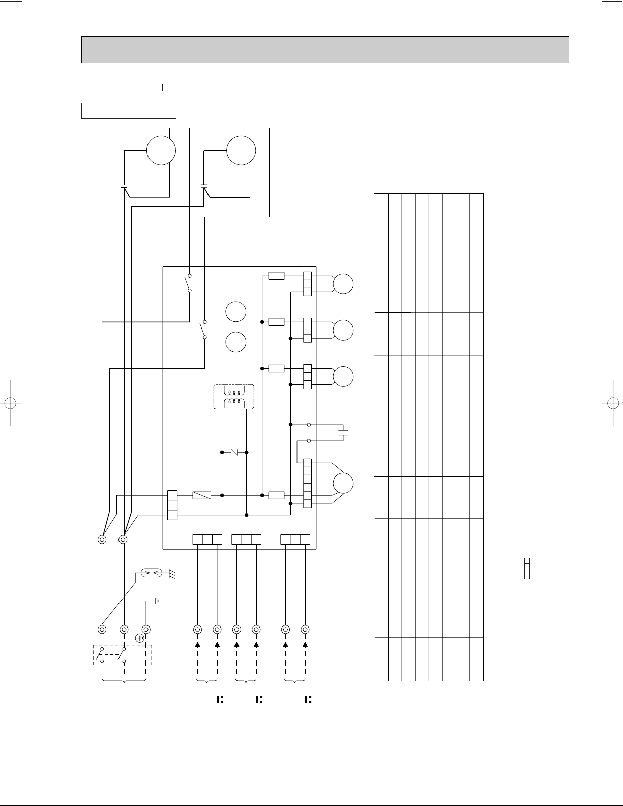
MU-A09WV MU-A12WV -
E1
E1
E1
OUTDOOR UNIT
FROM
INDOOR UNIT
CONNECTING
12V
POWER SUPPLY
~/N
230V 50Hz
MODELS WIRING DIAGRAM
TB2
2
WHT
1
BLK
CIRCUIT BREAKER
TB1
PE
L
BRN
N
BLU
GRN/YLW
NO
52C
52C
COM
BRN
WHT
WHT
C2
DSAR
C1
WHT
BLU
RED
RED
BLK
1
2
3
WHT
BLK
RED
C
MC
S
R
MF
SYMBOL
C1
COMPRESSOR CAPACITOR
C2
OUTDOOR FAN CAPACITOR
DSAR
NOTE:1. About the indoor side electric wiring refer to the indoor unit electric wiring diagram for servicing.
SURGE ABSORBER
2. Use copper conductors only. (For field wiring)
3. Symbols below indicate.
/: Terminal block, : Connector
MUH-A07WV MUH-A09WV MUH-A12WV -
NAME
SYMBOL
MC
MF
TB1,TB2
E1
E1
E1
MODELS WIRING DIAGRAM
NAME NAME
COMPRESSOR(INNER PROTECTOR)
OUTDOOR FAN MOTOR(INNER FUSE)
TERMINAL BLOCK
OUTDOOR UNIT
SYMBOL
52C
CONTACTOR
VG79B194H02
NOTE:1. About the indoor side electric wiring refer to the indoor unit electric wiring diagram for servicing.
2. Use copper conductors only. (For field wiring)
3. Symbols below indicate.
/: Terminal block, : Connector
26
VG79B195H02
Page 27
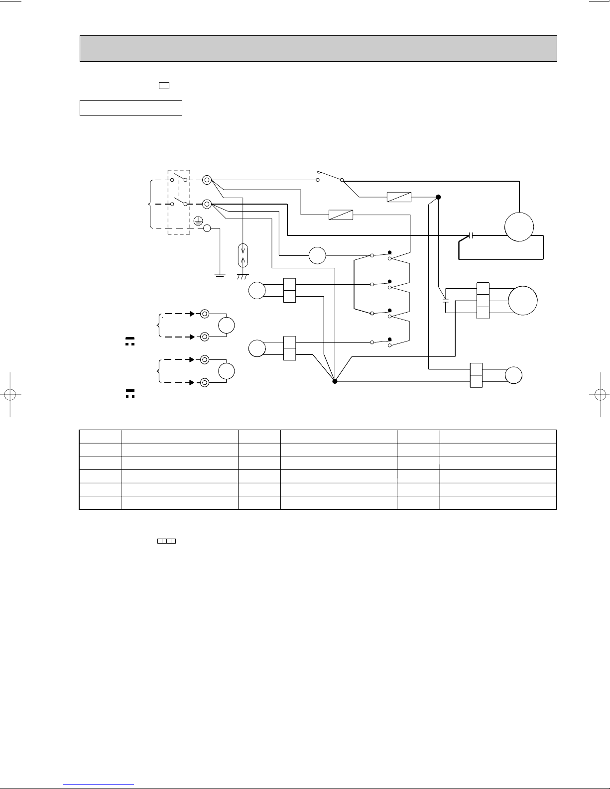
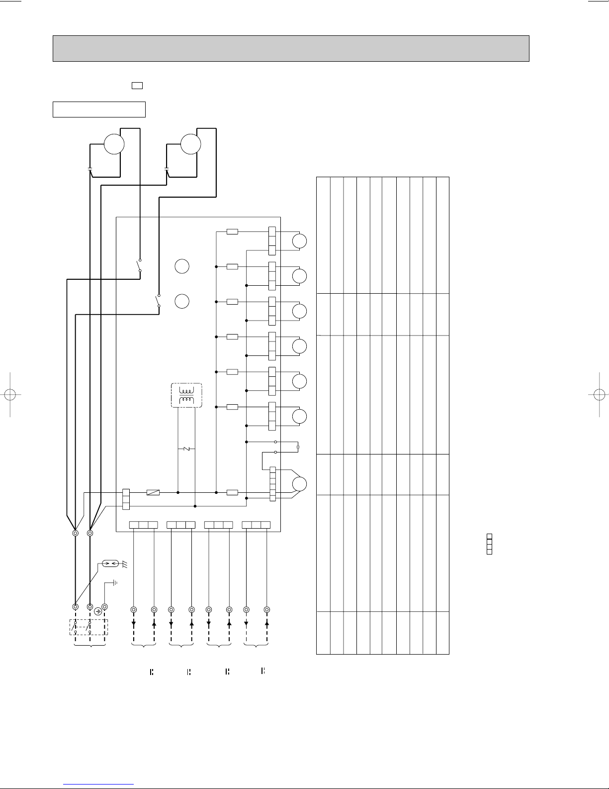
MUX-A10WV -
E1
OUTDOOR UNIT
POWER SUPPLY
~ / N
230V
50Hz
CIRCUIT BREAKER
FROM INDOOR
UNIT No.A
CONNECTING
12V
FROM INDOOR
UNIT No.B
CONNECTING
12V
MODEL WIRING DIAGRAM
TB1
2
1
2
1
L
N
PE
TB2
WHT
X1
BLK
YLW
X2
ORN
7
8
7
8
BRN
BRN
DSAR
21R1
21R2
BLU
BLU
BLU
BLU
BLU
BLU
BLU
2
1
2
1
NO
BRN
2
BLU
BLU
BLU
BLU
52C
52C
1
2
TB3
F61
BLU
COM
BRN
BLU
WHT
5
6
5
6
X1
X1
X2
X2
2
1
F62
1
3
4
3
2
4
WHT
BRN BRN BRN
WHT
1
TB3
WHT
C2
C1
WHT
BLU
RED
WHT
BLU
RED
1
2
3
2
1
WHT
BLK
RED
BLU
BLU
S
BLK
C
MC
21R
R
MF
SYMBOL
COMPRESSOR CAPACITOR
C1
OUTDOOR FAN CAPACITOR
C2
DSAR
F61,F62
NOTE:1. About the indoor side electric wiring refer to the indoor unit electric wiring diagram for servicing.
SURGE ABSORBER
FUSE(2A)
COMPRESSOR(INNER PROTECTOR)
MC
2. Use copper conductors only. (For field wiring)
3. Symbols below indicate.
/: Terminal block, : Connector
NAME
SYMBOL
OUTDOOR FAN MOTOR(INNER FUSE)
MF
TB1,TB2,TB3
21R
TERMINAL BLOCK
RELAY(A)
X1
RELAY(B)
X2
SOLENOID COIL
NAME NAME
SYMBOL
21R1
21R2
52C
SOLENOID COIL(A)
SOLENOID COIL(B)
COMPRESSOR CONTACTOR
VG79B203H01
27
Page 28
1
2
3
123
2
1
3
RED
RED
NR61
T61
1
2
4
3
4
3
C61
LD1
WHT
WHT
OUTDOOR CONTROL
P.C. BOARD
BRN
BLU
BRN
BLU
BRN
X522
X521
BLK
SR861
LD2
RED
BLK
WHT
6
52341
BRN
BLU
BLU
TB4
CN90
TB2
X521X522
F61
CN73
CN71
FROM INDOOR
UNIT B
CONNECTING
12V
PE
CIRCUIT BREAKER
GRN/YLW
ORN
CN91
BLU
YLW
BLU
RED
RED
FROM INDOOR
UNIT A
CONNECTING
12V
1
2
C2
C1
RC
S
C
R
S
MC2
MF61
MC1
BLK
TB1
POWER SUPPLY
~/N
230V
50Hz
1
2
L
N
DSAR
BRN
MUX-A19WV MUX-A25WV -
OUTDOOR UNIT
E1
E1
MODELS WIRING DIAGRAM
SYMBOL
C1
C2
C61
DSAR
F61
NOTE:1. About the indoor side electric wiring refer to the indoor unit electric wiring diagram for servicing.
NAME
COMPRESSOR CAPACITOR(MC1)
COMPRESSOR CAPACITOR(MC2)
OUTDOOR FAN CAPACITOR
SURGE ABSORBER
FUSE(3.15A)
2. Use copper conductors only. (For field wiring)
3. Symbols below indicate.
/: Terminal block, : Connector
SYMBOL
MC1
MC2
MF61
NR61
SR861
COMPRESSOR(INNER PROTECTOR)
COMPRESSOR(INNER PROTECTOR)
OUTDOOR FAN MOTOR (INNER PROTECTOR)
SURGE ABSORBER
OUTDOOR FAN RELAY
NAME NAME
SYMBOL
TB1
TB2~TB4
T61
X521
X522
TERMINAL BLOCK
TERMINAL BLOCK
TRANSFORMER
COMPRESSOR CONTACTOR(MC1)
COMPRESSOR CONTACTOR(MC2)
VG79B200H02
28
Page 29
SYMBOL
MF61
NR61
SR861
SR863
SR865
SR866
TB1
SYMBOL
C1
C2
C61
DSAR
F61
MC1
MC2
NAME
NAME NAME
COMPRESSOR CAPACITOR(MC1)
COMPRESSOR CAPACITOR(MC2)
OUTDOOR FAN CAPACITOR
SURGE ABSORBER
FUSE(3.15A)
COMPRESSOR(INNER PROTECTOR)
COMPRESSOR(INNER PROTECTOR)
OUTDOOR FAN MOTOR(INNER PROTECTOR)
SURGE ABSORBER
OUTDOOR FAN RELAY
RELAY (21RB)
RELAY (C) (21R4)
RELAY (B) (21R3)
TERMINAL BLOCK
TERMINAL BLOCK
TRANS FORMER
COMPRESSOR CONTACTOR(MC1)
COMPRESSOR CONTACTOR(MC2)
SOLENOID COIL
SOLENOID COIL (B)
SOLENOID COIL (C)
SYMBOL
TB2~TB4
T61
X521
X522
21RB
21R3
21R4
MUX-A20WV -
E1
OUTDOOR UNIT
S
MC1
RED
C1
BLU
BLU
BRN
BRN
CR
BLK
WHT
X521
MODEL WIRING DIAGRAM
S
MC2
RED
C2
43
43
X522
RC
WHT
BLK
SR865
X521
SR866
X522
SR863
T61
CN86
123123123
CN85
CN81
BLU
BLU
BLU
BLU
BLU
BLU
VG79B201H02
21R421R3
21RB
TB4
2
BRN
TB1
L
1
BLU
N
BRN
PE
OUTDOOR CONTROL P.C. BOARD
CN90
BRN
123
BLU
DSAR
GRN/YLW
CIRCUIT BREAKER
BLU
TB2
2
F61
213
YLW
1
CN71
NR61
3
BLU
2
2
ORN
1
CN73
1
SR861
3
BLU
TB3
2
2
WHT
1
LD1
LD2
652341
CN74
CN91
1
RED
RED
RED
BLK
WHT
C61
MF61
2. Use copper conductors only. (For field wiring)
/: Terminal block, : Connector
3. Symbols below indicate.
NOTE:1. About the indoor side electric wiring refer to the indoor unit electric wiring diagram for servicing.
POWER SUPPLY
~/N
230V
50Hz
FROM INDOOR
UNIT A
FROM INDOOR
UNIT B
CONNECTING
CONNECTING
12V
12V
FROM INDOOR
UNIT C
CONNECTING
12V
29
Page 30
DSAR
CIRCUIT BREAKER
L
N
2
1
2
112
1
2
BLK
RED
MF61
21R1
BLU
BLU
RED
RED
OUTDOOR CONTROL P.C. BOARD
T61
34
43
X521
X522
MC1
S
RC
MC2
S
RC
C1
C2
BLK
RED
WHT
RED
BLK
WHT
X522 X521
13
3
1
3
113
1
3
621
CONNECTING
FROM INDOOR
POWER SUPPLY
WHT
BLU
ORN
BLU
BRN
BLU
YLW
CN74CN73CN72CN71
TB1
TB3
TB2
2
2
2
2
2
BRN
BLU
TB4
2
1
BLU
F61
BRN
BLU
SR861
CN91
435
SR868
BLU
BLU
BRN
BRN
LD1
LD2
C61
NR61
CN90
WHT
123 123
21R2
BLU
BLU
SR867
21R3
BLU
BLU
SR866
123
BLU
BLU
21R4
123
SR865
BLU
BLU
21RA
123
SR864
BLU
BLU
21RB
123
SR863
CN83 CN84 CN85 CN86 CN81CN82
~/N
12V
230V
50Hz
UNIT C
FROM INDOOR
CONNECTING
12V
UNIT A
PE
GRN/YLW
FROM INDOOR
CONNECTING
UNIT D
12V
CONNECTING
FROM INDOOR
12V
UNIT B
BRN
SYMBOL
SR861
SR863
SR864
SR865
SR866
SR867
SR868
TB1~TB4
T61
SYMBOL
C1
C2
C61
DSAR
F61
MC1
MC2
MF61
NR61
NAME
NAME NAME
COMPRESSOR CAPACITOR(MC1)
COMPRESSOR CAPACITOR(MC2)
OUTDOOR FAN CAPACITOR
SURGE ABSORBER
FUSE(3.15A)
COMPRESSOR(INNER PROTECTOR)
COMPRESSOR(INNER PROTECTOR)
OUTDOOR FAN MOTOR(INNER PROTECTOR)
SURGE ABSORBER
OUTDOOR FAN RELAY
RELAY (21RB)
RELAY (21RA)
RELAY (D) (21R4)
RELAY (C) (21R3)
RELAY (B) (21R2)
RELAY (A) (21R1)
TERMINAL BLOCK
TRANS FORMER
COMPRESSOR CONTACTOR(MC1)
COMPRESSOR CONTACTOR(MC2)
SOLENOID COIL (BALANCE)
SOLENOID COIL (BALANCE)
SOLENOID COIL (A)
SOLENOID COIL (B)
SOLENOID COIL (C)
SOLENOID COIL (D)
SYMBOL
X521
X522
21RA
21RB
21R1
21R2
21R3
21R4
MUX-A26WV -
E1
OUTDOOR UNIT
MODEL WIRING DIAGRAM
VG79B198H03
2. Use copper conductors only. (For field wiring)
/: Terminal block, : Connector
3. Symbols below indicate.
NOTE:1. About the indoor side electric wiring refer to the indoor unit electric wiring diagram for servicing.
30
Page 31

OUTDOOR UNIT
MODEL MXZ-A18WV-
E1
TO INDOOR
UNIT No.A
CONNECTING
12V
TO INDOOR
UNIT No.B
CONNECTING
12V
CIRCUIT
BREAKER
POWER
SUPPLY
~/N
230V
50Hz
TB1
L
N
BLK
PE
TB2
3
N
3
N
F61
BLU
BLK
TAB1
TAB2
GRN
LDE
GRN/YLW
X62
X61
C65
45
CN911
BLK
WHT
RED
YLW
MF
SYMBOL
ACTIVE FILTER MODULEAFM
CT61 CURRENT TRANSFORMER
CT761
CURRENT TRANSFORMER
C61 SMOOTHING CAPACITOR
C62
SMOOTHING CAPACITOR
C63
SMOOTHING CAPACITOR
C65 FAN MOTOR CAPACITOR
DS61 DIODE MODULE
DS62 DIODE MODULE
F61 FUSE(20A)
F801 FUSE(1A)
F911 FUSE(1A)
F912 FUSE(3.15A)
IPM POWER TRANSISTOR MODULE
L
REACTOR
NAME
F912
NR63
X64
R64BR64A
BLU
3
NF
CT61
TAB4
3131
F911
7
CN901
SSR61
TAB65
2113
BRN
BRN
21S4
NOISE
FILTER
P.C.BOARD
CN912
SYMBOL
CN61
U
BLK
V
MC
W
NAME
LEV(A) EXPANSION VALVE A,COIL
LEV(B)
EXPANSION VALVE B,COIL
L63
NORMAL MODE CHOKE COIL
COMPRESSOR
MC
FAN MOTOR
MF
NF NOISE FILTER
NR63
VARISTOR
RT6A
GAS PIPE TEMP.A THERMISTOR
RT6B GAS PIPE TEMP.B THERMISTOR
RT61
DISCHARGE TEMP.THERMISTOR
RT62 DEFROST TEMP.THERMISTOR
EVAPORATOR TEMP.THERMISTOR
RT63
RT65 FIN TEMP.THERMISTOR
RT68
HIGH-PRESSURE PROTECT THERMISTOR
R62
RESISTOR
BLU
ORN
CT761
CN851
TAB66
WHT
BLK
RED
123 56781234341212
WHT
RED
CN601CN602
N
WVUP
IPM
TAB67
RT65
TAB61 TAB63
ORN
RED
L63
TAB62
BLU
R62
C63
F801
T801
C62
C61
ELECTRONIC
CONTROL
P.C.BOARD
RT6A RT6B RT62 RT61 RT63 RT68
SYMBOL
NAME
RESISTORR64A
R64B
RESISTOR
SOLENOID COIL RELAY
SSR61
TB1 TERMINAL BLOCK
TB2 TERMINAL BLOCK
T801
TRANSFORMER
FAN MOTOR RELAY
X61
FAN MOTOR RELAY
X62
RELAY
X64
REVERSING VALVE SOLENOID COIL
21S4
1.About the indoor side electric wiringNOTES
refer to the indoor unit electric wiring
diagram for servicing.
2.Use copper conductors only(for field wiring).
3.Symbols below indicate.
:Terminal block :Connector
DS61
AFM
CN662CN661CN663
DS62
TAB64
CN771CN772
BLK
BLK
6
6
L
LEV
(A)
LEV
(B)
SG79J614H02
31
Page 32

9
REFRIGERANT SYSTEM DIAGRAM
MSC-A07WV MSC-A09WV -
Unit:mm
E1
E1
MU-A07WV MU-A09WV -
E1
E1
INDOOR UNIT
Indoor
heat
exchanger
Room temperature
thermistor
RT11
Indoor coil
thermistor
RT12
MSC-A12WV -
INDOOR UNIT
Refrigerant pipe
(with heat insulator)
Flared connection
Flared connection
Refrigerant pipe [6.35
(with heat insulator)
E1
Refrigerant pipe [12.7
(with heat insulator)
[9.52
Stop valve
(with service port)
Compressor
Capillary tube
[3.0x[1.4x500(MU-A07WV)
[3.0x[1.4x700(MU-A09WV)
OUTDOOR UNIT
Muffler
Outdoor
heat
exchanger
Strainer
Refrigerant flow in cooling
Unit:mm
MU-A12WV -
OUTDOOR UNIT
E1
Indoor
heat
exchanger
Room temperature
thermistor
RT11
Indoor coil
thermistor
RT12
Flared connection
Flared connection
Refrigerant pipe [6.35
(with heat insulator)
Stop valve
(with service port)
Stop valve
32
Muffler
Outdoor
heat
exchanger
Compressor
Strainer
Capillary tube
[3.0x[1.4x550
Refrigerant flow in cooling
Page 33

MSC-A07WV MSC-A09WV -
INDOOR UNIT
E1
E1
Refrigerant pipe [ 9.52
(with heat insulator)
4-way valve
Unit:mm
MUH-A07WV MUH-A09WV -
OUTDOOR UNIT
E1
E1
Indoor
heat
exchanger
Indoor coil
thermistor
RT12
Room temperature
thermistor
RT11
MSC-A12WV -
INDOOR UNIT
Defrost
thermistor
RT61
Outdoor
heat
exchanger
Flared connection
Stop valve
(with service
port)
Muffler
Capillary tube
[3.0x[1.4x800(2 pcs)
(MUH-A07WV)
[3.0x[1.4x500(2 pcs)
(MUH-A09WV)
R.V. coil
heating ON
cooling OFF
Flared connection
Strainer
Stop valve
Compressor
Capillary tube
[3.0x[1.6x350(MUH-A07WV)
[3.0x[1.6x600(MUH-A09WV)
Check valve
Capillary tube
[3.0x[1.4x1050(MUH-A07WV)
Refrigerant pipe [6.35
(with heat insulator)
[3.0x[1.4x1300(MUH-A09WV)
Refrigerant flow in cooling
Refrigerant flow in heating
Unit:mm
E1
Refrigerant pipe [12.7
4-way valve
MUH-A12WV -
OUTDOOR UNIT
E1
(with heat insulator)
Indoor
heat
exchanger
Indoor coil
thermistor
RT12
Flared connection
Room temperature
thermistor
RT11
Flared connection
Refrigerant pipe [6.35
(with heat insulator)
Stop valve
(with service port)
Strainer
Stop valve
33
Muffler
Compressor
Capillary tube
[3.0x[1.6x1350
Check
valve
Defrost
thermistor
RT61
Outdoor
heat
exchanger
Capillary tube
[3.0x[1.4x500(2pcs)
Capillary tube
[3.0x[1.6x400
R.V. coil
heating ON
cooling OFF
Refrigerant flow in cooling
Refrigerant flow in heating
Page 34

Piping size O.D : mm Length of connecting pipe : m
Model
Piping size O.D : mm Length of connecting pipe : m
Model
Refrigerant piping
Max. length : m
A
20
25
Indoor unit
Gas 0.43
Liquid 0.5
Gas
9.52
12.7
Liquid
6.35
Outdoor unit
Gas 0
Liquid 0
MSC-A07WV - E1
MUH-A07WV - E1
MSC-A09WV - E1
MUH-A09WV - E1
MSC-A12WV - E1
MUH-A12WV - E1
{
{
{
Refrigerant piping
Max. length : m
A
20
25
Indoor unit
Gas 0.43
Liquid 0.5
Gas
9.52
12.7
Liquid
6.35
Outdoor unit
Gas 0
Liquid 0
MSC-A07WV - E1
MU-A07WV - E1
MSC-A09WV - E1
MU-A09WV - E1
MSC-A12WV - E1
MU-A12WV - E1
{
{
{
Indoor
unit
w Max. Height
difference 10m
Height difference should be within
10m regardless of which unit,
indoor or outdoor position is high.
Outdoor unit
Refrigerant Piping
Max.length
A
Model
Refrigerant piping length (one way)
Model
Refrigerant piping length (one way)
7m
0
10m
60
15m
160
20m
260
MSC-A07WV - E1
MUH-A07WV - E1
MSC-A09WV - E1
MUH-A09WV - E1
MSC-A12WV - E1
MUH-A12WV - E1
{
{
{
Calculation : Xg=20g/m 5 x(A-7)m
Outdoor unit precharged
750
800
830
25m
360
25m
360
7m
0
10m
60
15m
160
20m
260
MSC-A07WV - E1
MU-A07WV - E1
MSC-A09WV - E1
MU-A09WV - E1
MSC-A12WV - E1
MU-A12WV - E1
{
{
{
Calculation : Xg=20g/m x(A-7)m
Outdoor unit precharged
750
1100
1150
MAX. REFRIGERANT PIPING LENGTH
MAX. HEIGHT DIFFERENCE
ADDITIONAL REFRIGERANT CHARGE(R410A : g)
34
Page 35

MSC-A07WV-
UNIT A
E1
Room
temperature
thermistor
RT11
Indoor
heat
exchanger
Indoor coil
thermistor
RT12
Room
temperature
thermistor
RT11
Refrigerant pipe
9.52
(With insulation)
Flared connection
Refrigerant pipe
6.35
(With insulation)
Refrigerant pipe
9.52
(With insulation)
Stop valve
with service port
Solenoid valve
21R1
Stop
valve
Capillary tube
[3.0 x [1.4 x 400
Capillary tube
[3.0 x [1.4 x 1000
Compressor
Capillary tube
[3.0 x [1.6 x 900
Strainer
Strainer
MUX-A10WV-
OUTDOOR UNITINDOOR UNIT
Solenoid
valve
21R
Muffler
E1
Outdoor
heat
exchanger
Unit : mm
UNIT B
MSX-A10WV-
Indoor
heat
exchanger
Indoor coil
thermistor
RT12
E1
Flared connection
Refrigerant pipe
6.35
(With insulation)
Stop valve
with service port
Solenoid valve
21R2
Stop
valve
[3.0 x [1.4 x 400
Capillary tube
Refrigerant flow in cooling
MAX. REFRIGERANT PIPING LENGTH & MAX. HEIGHT DIFFERENCE
Outdoor unit
MUX-A10WV
Indoor unit A
MSC-A07WV
E1
E1
Additional piping max. length 15m
Indoor unit B
MSC-A07WV
E1
Max. length
difference
10m
ADDITIONAL REFRIGERANT CHARGE (R410A:g)
UNIT No.
BA
unit + unit
Outdoor unit
precharged
1000g
10m11m12m13m14m15m16m17m18m19m20m21m22m23m24m25m26m27m28m29m30
0 102030405060
Refrigerant piping length (one way)
70 80 90 100 110 120 130 140 150 160 170 180 190 200
m
PIPING PREPARATION
1 Table below shows the specifications of pipes commercially available.
UNIT No. Pipe
BA
and
UNIT
2 Ensure that the 2 refrigerant pipes are well insulated to prevent condensation.
3 Refrigerant bending radius must be 10cm or more.
For liquid 6.35 8 mm Heat resisting foam plastic
For gas 9.52 8 mm 0.045 specific gravity
Outside diameter Insulation
mm thickness
35
Insulation material
Page 36

OUTDOOR UNIT
INDOOR UNIT
UNIT A
Indoor
heat
exchanger
Indoor coil
thermistor
RT12
Room
temperature
thermistor
RT11
UNIT B
Indoor
heat
exchanger
Outdoor
heat
exchanger
Indoor coil
thermistor
RT12
Room
temperature
thermistor
RT11
(With insulation)
Refrigerant pipe
12.7
(With insulation)
Refrigerant pipe
9.52
(With insulation)
Refrigerant pipe
6.35
Flared connection
(With insulation)
Refrigerant pipe
6.35
Flared connection
Stop valve
with service port
Stop valve
Stop valve
with
service port
Capillary tube
Capillary tube
Strainer
Muffler
Muffler
Strainer
Compressor(A)
Compressor(B)
Refrigerant flow in cooling
MSC-A12WV
E1
MSC-A07WV
E1
Stop valve
[3.0 x [1.4 x 850
[3.0 x [1.4 x 1100
Unit : mm
MSC-A07WVMSC-A12WV-
E1
E1
MUX-A19WV-
E1
36
Page 37

MSX-A19WV-
E1
MAX.REFRIGERANT PIPING LENGTH & MAX. HEIGHT DIFFERENCE
Max.
limits
MUX-A19WV - E1
UNIT No.
A
B
Indoor unit A
MSC-A12WV - E1
Outdoor unit
A
L
LB
LA
Pipe length
15m
15m
Indoor unit B
MSC-A07WV - E1
HL
B H
Height difference (H)
10m
10m
No. of bends
10
10
ADDITIONAL REFRIGERANT CHARGE (R410A:g)
Outdoor unit
A
unit
B
unit
precharged
1000g
Outdoor unit
precharged
800g
7m
0
7m
8m
20
8m
0
20
Refrigerant piping length (one way)
9m
40
Refrigerant piping length (one way,2 unit total)
9m4010m6011m8012m
10m6011m8012m
PIPING PREPARATION
1Table below shows the specifications of pipes commercially available.
UNIT No.
A
unit
B
unit
2Ensure that the 2 refrigerant pipes are well insulated to prevent condensation.
3Refrigerant bending radius must be 10cm or more.
Pipe
For liquid
For gas
For liquid
For gas
Outside diameter
mm
6.35
12.7
6.35
9.52
Insulation
thickness
8mm
8mm
8mm
8mm
13m
100
100
Heat resisting foam plastic
0.045 specific gravity
120
13m
120
Insulation material
14m
140
14m
140
15m
160
15m
160
37
Page 38
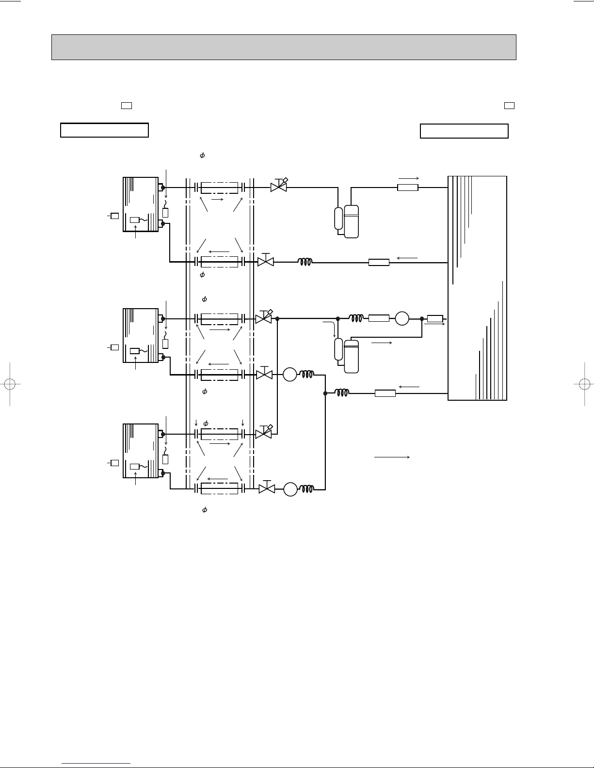
Unit : mm
OUTDOOR UNIT
INDOOR UNIT
UNIT A
Indoor
heat
exchanger
Indoor coil
thermistor
RT12
Room
temperature
thermistor
RT11
UNIT B
Indoor
heat
exchanger
Outdoor
heat
exchanger
Indoor coil
thermistor
RT12
Room
temperature
thermistor
RT11
(With insulation)
Refrigerant pipe
9.52
(With insulation)
Refrigerant pipe
9.52
(With insulation)
Refrigerant pipe
6.35
Flared connection
(With insulation)
Refrigerant pipe
6.35
Flared connection
Refrigerant pipe
9.52
(With insulation)
Refrigerant pipe
6.35
Flared connection
Stop valve
with service port
Stop valve
Solenoid valve
21R3
Solenoid valve
21R4
Solenoid
valve
21RB
Stop valve
with
service port
Stop valve
with
service port
Capillary tube
Capillary tube
Capillary tube
Capillary tube
Capillary tube
Compressor(A)
Compressor(B,C)
Refrigerant flow in cooling
MSC-A09WV
E1
MSC-A09WV
E1
UNIT C
Indoor
heat
exchanger
Indoor coil
thermistor
RT12
Room
temperature
thermistor
RT11
MSC-A09WV
E1
Strainer
Stop
valve
Stop
valve
Strainer
Strainer
Muffler
Muffler
[3.0 x [1.4 x 950
[3.0 x [1.4 x 1000
[3.0 x [1.6 x 900
[3.0 x [1.6 x 900
[3.0 x [1.6 x 900
MSC-A09WV-
E1
MUX-A20WV-
E1
38
Page 39

MSX-A20WV-
E1
MAX.REFRIGERANT PIPING LENGTH & MAX. HEIGHT DIFFERENCE
Outdoor unit
MUX-A20WV - E1
Max.
limits
Indoor unit A
MSC-A09WV - E1
LA
UNIT No.
A
B
C
L
LB
LC
Indoor unit B
MSC-A09WV - E1
HL
B HLC
Pipe length
A
15m
15m
15m
L
+
LC
B
Total
30m
Indoor unit C
MSC-A09WV - E1
Height difference (H)
10m
10m
10m
No. of bends
10
10
10
H
Total
15
ADDITIONAL REFRIGERANT CHARGE (R410A:g)
Refrigerant piping length (one way)
9m
40
10m
50
Refrigerant piping length (one way, 2 unit total)
70 80 90 100 110 120 130 140 150 160 170 180 190 200
A
unit
CB
unit + unit
Outdoor unit
precharged
800g
Outdoor unit
precharged
1000g
7m
0
8m
20
10m11m12m13m14m15m16m17m18m19m20m21m22m23m24m25m26m27m28m29m30
0 102030405060
PIPING PREPARATION
1Table below shows the specifications of pipes commercially available.
UNIT No.
BA
, and
C
unit
Pipe
For liquid
For gas
2Ensure that the 2 refrigerant pipes are well insulated to prevent condensation.
3Refrigerant bending radius must be 100mm or more.
Outside diameter
mm
6.35
9.52
11m
80
Insulation
thickness
8mm
8mm
12m
100
13m
120
14m
140
Insulation material
Heat resisting foam plastic
0.045 specific gravity
15m
160
m
39
Page 40

OUTDOOR UNIT
INDOOR UNIT
UNIT A
Indoor
heat
exchanger
Indoor coil
thermistor
RT12
Room
temperature
thermistor
RT11
UNIT B
Indoor
heat
exchanger
Outdoor
heat
exchanger
Indoor coil
thermistor
RT12
Room
temperature
thermistor
RT11
(With insulation)
Refrigerant pipe
12.7
(With insulation)
Refrigerant pipe
12.7
(With insulation)
Refrigerant pipe
6.35
Flared connection
(With insulation)
Refrigerant pipe
6.35
Flared connection
Stop valve
with service port
Stop valve
Stop valve
with
service port
Capillary tube
Capillary tube
Strainer
Muffler
Muffler
Strainer
Compressor(A)
Compressor(B)
Refrigerant flow in cooling
MSC-A12WV
E1
MSC-A12WV
E1
Stop valve
[3.0 x [1.4 x 700
[3.0 x [1.4 x 700
Unit : mm
MSC-A12WV-
E1
MUX-A25WV-
E1
40
Page 41

MSX-A25WV-
E1
MAX.REFRIGERANT PIPING LENGTH & MAX. HEIGHT DIFFERENCE
Indoor unit A
MSC-A12WV - E1
Max.
limits
UNIT No.
A
B
LA
Outdoor unit
MUX-A25WV - E1
Pipe length
LA
LB
HL
15m
15m
ADDITIONAL REFRIGERANT CHARGE (R410A:g)
Outdoor unit
A
unit
B
unit
precharged
950g
Outdoor unit
precharged
950g
7m
0
7m
0
8m
20
8m
20
9m
40
9m
40
Indoor unit B
MSC-A12WV - E1
B H
Height difference (H)
10m
10m
Refrigerant piping length (one way)
10m6011m8012m
100
Refrigerant piping length (one way)
10m6011m8012m
100
13m
120
13m
120
No. of bends
10
10
14m
140
14m
140
15m
160
15m
160
PIPING PREPARATION
1Table below shows the specifications of pipes commercially available.
UNIT No.
BA
and unit
2Ensure that the 2 refrigerant pipes are well insulated to prevent condensation.
3Refrigerant bending radius must be 10cm or more.
Pipe
For liquid
For gas
Outside diameter
mm
6.35
12.7
41
Insulation
thickness
8mm
8mm
Insulation material
Heat resisting foam plastic
0.045 specific gravity
Page 42
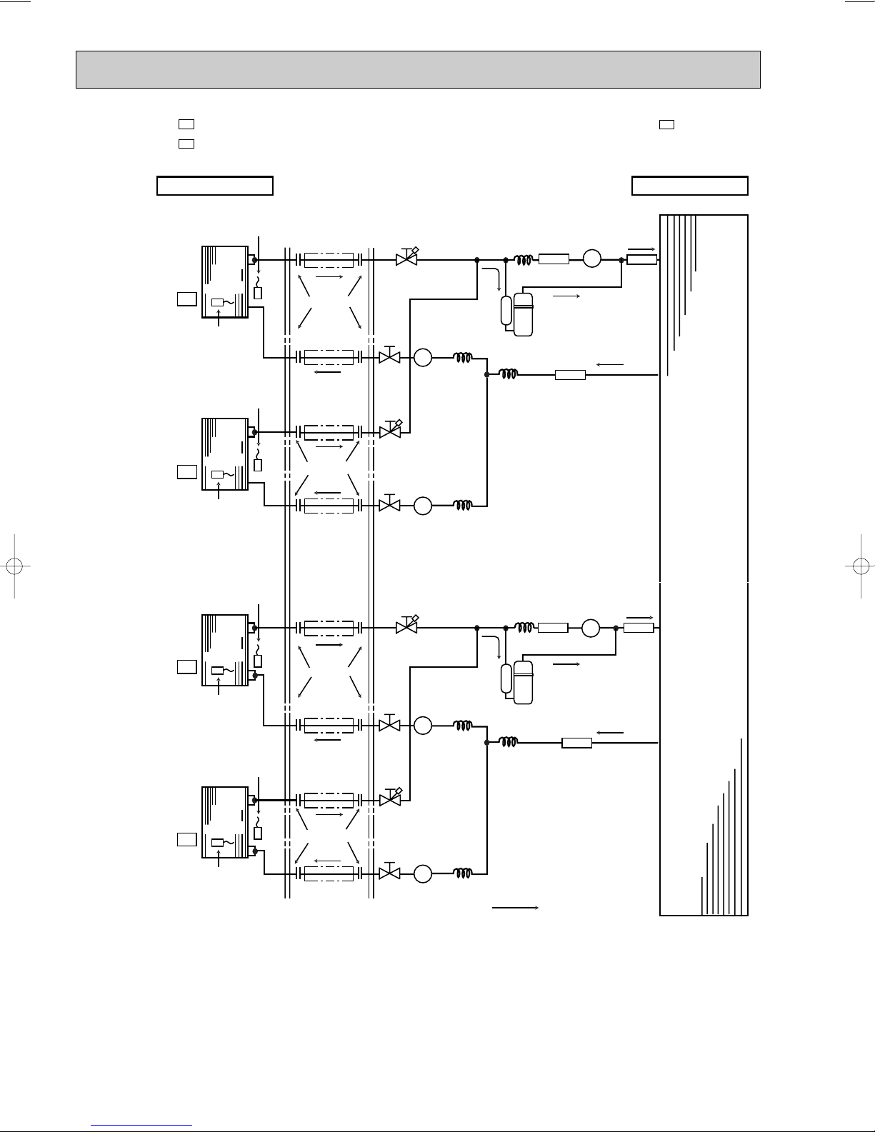
MSC-A09WV-
OUTDOOR UNITINDOOR UNIT
UNIT A
Indoor
heat
exchanger
Indoor coil
thermistor
RT12
Room
temperature
thermistor
RT11
UNIT B
Indoor
heat
exchanger
Outdoor
heat
exchanger
Indoor coil
thermistor
RT12
Room
temperature
thermistor
RT11
(With insulation)
Refrigerant pipe
{12.7
(With insulation)
Refrigerant pipe
{12.7
Flared connection
(With insulation)
Refrigerant pipe
{6.35
(With insulation)
Refrigerant pipe
{6.35
Flared connection
Stop valve
with service port
Solenoid valve
21R1
Solenoid
valve
21RA
Solenoid valve
21R2
Capillary tube
Capillary tube
Capillary tube
Capillary tube
Compressor 1
Refrigerant flow in cooling
Stop valve
with service port
Stop
valve
Stop
valve
UNIT C
Indoor
heat
exchanger
Indoor coil
thermistor
RT12
Room
temperature
thermistor
RT11
UNIT D
Indoor
heat
exchanger
Indoor coil
thermistor
RT12
Room
temperature
thermistor
RT11
(With insulation)
Refrigerant pipe
{9.52
(With insulation)
Refrigerant pipe
{9.52
Flared connection
(With insulation)
Refrigerant pipe
{6.35
(With insulation)
Refrigerant pipe
{6.35
Flared connection
Stop valve
with service port
Solenoid valve
21R3
Solenoid
valve
21RB
Solenoid valve
21R4
Capillary tube
Capillary tube
Capillary tube
Capillary tube
Compressor 2
Stop valve
with service port
Stop
valve
Stop
valve
MSC-A09WV- E1
MSC-A09WV- E1
Strainer
Strainer
Muffler
Strainer
Strainer
Muffler
MSC-A12WV- E1
MSC-A12WV- E1
[3.0 x [1.4 x 1000
[3.0 x [2.0 x 700
[3.0 x [1.8 x 700
[3.0 x [1.8 x 700
[3.0 x [1.4 x 1000
[3.0 x [1.8 x 800
[3.0 x [1.6 x 600
[3.0 x [1.6 x 600
MSC-A12WV-
E1
E1
MUX-A26WV-
E1
Unit : mm
42
Page 43

MSX-A26WV-
E1
MAX.REFRIGERANT PIPING LENGTH & MAX. HEIGHT DIFFERENCE
Outdoor unit
MUX-A26WV- E1
Max.
limits
Indoor unit A
MSC-A12WV- E1
UNIT No.
A
B
C
D
LA
LB
LC
LD
Indoor unit B
MSC-A12WV- E1
Pipe length
15m
15m
15m
15m
LA
LB
LC
LD
Indoor unit C
MSC-A09WV- E1
Height difference (H)
+
+
Total
30m
Total
30m
10m
10m
10m
10m
Indoor unit D
MSC-A09WV- E1
No. of bends
10
10
10
10
HLDHLCHLBHLA
Total
15
Total
15
ADDITIONAL REFRIGERANT CHARGE (R410A:g)
UNIT No.
BA
unit + unit
DC
unit + unit
Outdoor unit
precharged
1050g
1050g
10m11m12m13m14m15m16m17m18m19m20m21m22m23m24m25m26m27m28m29m30
0 102030405060
0
10 20 30 40 50 60
Refrigerant piping length (one way, 2 unit total)
70 80 90 100 110 120 130 140 150 160 170 180 190 200
70 80 90 100 110 120 130 140 150 160 170 180 190 200
PIPING PREPARATION
UNIT No.
BA
and unit
DC
and unit
Pipe
For liquid
For gas
For liquid
For gas
Outside diameter
mm
6.35
12.7
6.35
9.52
43
Insulation
thickness
8mm
8mm
8mm
8mm
m
Insulation material
Heat resisting foam plastic
0.045 specific gravity
Page 44

MXZ-A18WV -
High pressure
protect thermistor
Compressor
Discharge
temperature
thermistor
R.V. coil
heating ON
cooling OFF
Refrigerant flow in cooling
Refrigerant flow in heating
Muffler
Outdoor
heat
exchanger
Muffler
LEV (A)
Evaporation
temperature
thermistor
LEV (B)
Strainer
Strainer
Strainer
Defrost
thermistor
Capillary tube
{3.0✕{1.8✕600
Capillary tube
{1.8✕{0.6✕750
Capillary tube
{3.0✕{2.0✕400
Capillary tube
{3.0✕{2.0✕400
Stop valve
(with service port)
Gas pipe temperature
B thermistor
Gas pipe temperature
A thermistor
Stop valve
Stop valve
Indoor
Unit B
Indoor
Unit B
Indoor
Unit A
Indoor
Unit A
Stop valve
(with service port)
4-way valve
{8
{6
{6
{12
{12
a
Outdoor
unit
b
H
H
H
E1
Unit:mm
MAX REFRIGERANT PIPING LENGTH
-
MXY-A18WV
Piping length each indoor unit (a, b) 20m
Total piping length (a+b) 30m
Height difference between units (H) 10m
Bending point for each unit 15
Total bending point 30
❋It does not matter which unit is higher.
● Refrigerant pipe diameter is different according to indoor unit to be connected. When using extension pipes, refer to the
tables below.
● When diameter of refrigerant pipe is different from that of outdoor unit union, use optional Different-diameter pipe.
For further information on Different-diameter pipe, see page BACK COVER.
class Pipe diameter
07/09
12
Liquid 6.35(1/4) Liquid 6.35(1/4)
Liquid 6.35(1/4) Liquid 6.35(1/4)
E1
Indoor unit
Gas 9.52(3/8) Gas 9.52(3/8)
Gas 12.7(1/2) Gas 12.7(1/2)
Extension pipe diameter
44
Outdoor unit union diameter
For
Indoor unit A
Indoor unit B
Unit : mm (inch)
Liquid 6.35(1/4)
Gas 9.52(3/8)
Liquid 6.35(1/4)
Gas 9.52(3/8)
Page 45

10
Wet-and dry-bulb
thermometers
Wet-and dry-bulb
thermometers
MSC-A07WV - E1
(MU-A07WV - E1 )
(MU-A12WV - E1 )
MSC-A12WV - E1
(MU-A09WV - E1 )
MSC-A09WV - E1
8.5
7.8
7.1
6.4
5.8
5.1
9.6
8.8
8.0
7.2
6.5
5.7
10.8
9.8
8.9
8.1
7.2
6.4
PERFORMANCE CURVES
MSC-A07WV - MU-A07WV - MUH-A07WV - MUX-A10WV - MUX-A25WV MSC-A09WV - MU-A09WV - MUH-A09WV - MUX-A19WV - MUX-A26WV MSC-A12WV - MU-A12WV - MUH-A12WV - MUX-A20WV - MXZ-A18WV -
The standard data contained in these specifications apply only to the operation of the air conditioner under normal conditions,
since operating conditions vary according to the areas where these units are installed. The following information has been provided to clarify the operating characteristics of the air conditioner under the conditions indicated by the performance curve.
E1E1E1E1E1
E1E1E1E1E1
E1E1E1E1E1
(1) GUARANTEED VOLTAGE
198~264V
(2) AIR FLOW
Air flow should be set at MAX.
(3) MAIN READINGS
(1) Indoor intake air wet-bulb temperature : °CWB
(2) Indoor outlet air wet-bulb temperature : °CWB
(3) Outdoor intake air dry-bulb temperature : °CDB
(4) Total input: W
(5) Indoor intake air dry-bulb temperature : °CDB
(6) Outdoor intake air wet-bulb temperature : °CWB
(7) Total input : W
Indoor air wet/dry-bulb temperature difference on the left side of the chart on page 41,42 and 45 shows the difference
between the indoor intake air wet/dry-bulb temperature and the indoor outlet air wet/dry-bulb temperature for your reference at service.
Cooling
}
Heating
}
<MUH-A07/A09/A12WV>
How to measure the indoor air wet-bulb/dry-bulb temperature difference
1. Attach at least 2 sets of wet-and dry-bulb thermometers to the indoor air intake as shown in the figure, and at least 2 sets
of wet-and dry-bulb thermometers to the indoor air outlet. The thermometers must be attached to the position where air
speed is high.
2. Attach at least 2 sets of wet-and dry-bulb thermometers to the outdoor air intake.
Cover the thermometers to prevent direct rays of the sun.
3. Check that the air filter is cleaned.
4. Open windows and doors of room.
5. Press the EMERGENCY OPERATION switch once(twice) to start the EMERGENCY COOL
(HEAT
<MUH-A07/A09/A12WV>) MODE.
6. When system stabilizes after more than 15 minutes, measure temperature and take an average temperature.
7. 10 minutes later, measure temperature again and check that the temperature does not change.
INDOOR UNIT
10-1.CAPACITY AND THE INPUT CURVES
45
OUTDOOR UNIT
Page 46

10
12
9
8
7
15 20
50
25
60
30
70(%)
35(:)
0.7
0.8
0.9
1.0
1.2
11
1.1
230V
15 20
50
25
603070(%)
35(:)
2.0
2.5
3.0
3.5
4.0
230V
MSC-A07WV - E1
(MUH-A07WV - E1 )
(MUH-A12WV - E1 )
MSC-A12WV - E1
(MUH-A09WV - E1 )
MSC-A09WV - E1
8.5
7.8
7.1
6.4
5.8
5.1
9.6
8.8
8.0
7.2
6.5
5.1
10.6
9.7
8.8
7.9
7.1
6.3
20.4
18.8
17.2
15.7
14.1
12.5
11.0
9.4
19.2
17.8
16.3
14.8
13.3
11.8
10.4
8.9
MSC-A07WV - E1
(MUH-A07WV - E1 )
(MUH-A09WV - E1 )
MSC-A09WV -
E1
(MUH-A12WV - E1 )
MSC-A12WV - E1
25.2
23.3
21.4
19.4
17.5
15.5
13.6
11.7
NOTE:The above curves are for the heating operation without any frost.
10-2.OUTDOOR LOW PRESSURE AND OUTDOOR UNIT CURRENT
COOL operation
① Both indoor and outdoor unit are under the same temperature/humidity condition.
Dry-bulb temperature
Relative humidity(%)
20
25
30 70
➁ Air flow should be set at MAX.
③ The unit of pressure has been changed to MPa on the international system of units(SI unit system).
The conversion factor is : 1(MPa[Gauge]) =10.2(kgf/
(kgf/F[Gauge])(MPa[Gauge])
Outdoor low pressure
MU-A07WV -
Ambient temperature(˚C)
Ambient humidity(%)
50
60
E1
ff
[Gauge] )
46
MU-A07WV -
Outdoor unit current (A)
Ambient temperature(˚C)
Ambient humidity(%)
E1
Page 47

15 20
50
256030
70(%)
35(:)
2.0
2.5
3.0
3.5
4.0
230V
10
11
12
9
8
7
15 20
502560
30
70(%)
35(:)
0.7
0.8
0.9
1.0
1.2
1.1
230V
15 20
50
25
60
30
70(%)
35(:)
0.7
0.8
0.9
1.0
1.2
10
11
12
1.1
9
8
7
230V
15 20
50
25
60
30
70(%)
35(:)
2.0
2.5
3.0
3.5
4.0
230V
15 20
50
25
60
30
70(%)
35(:)
0.7
0.8
0.9
1.0
1.2
10
11
12
1.1
9
8
7
230V
15 205025
60
30
70(%)
35(:)
2.0
2.5
3.0
3.5
4.0
230V
(kgf/F[Gauge])(MPa[Gauge])
MU-A09WV -
E1
MU-A09WV -
E1
Outdoor low pressure
Ambient temperature(˚C)
Ambient humidity(%)
(kgf/F[Gauge])(MPa[Gauge])
1.2
12
1.1
11
1.0
10
0.9
9
0.8
8
Outdoor low pressure
0.7
7
15 20
Ambient temperature(˚C)
Ambient humidity(%)
(kgf/F[Gauge])(MPa[Gauge])
MU-A12WV -
256030
50
70(%)
MUH-A07WV -
E1
230V
35(:)
E1
Outdoor unit current (A)
Ambient temperature(˚C)
Ambient humidity(%)
MU-A12WV -
7.0
6.0
5.0
4.0
Outdoor unit current (A)
3.0
15 20
50
Ambient temperature(˚C)
Ambient humidity(%)
MUH-A07WV -
E1
230V
25
30
60
35(:)
70(%)
E1
Outdoor low pressure
Ambient temperature(˚C)
Ambient humidity(%)
(kgf/F[Gauge])(MPa[Gauge])
Outdoor low pressure
MUH-A09WV -
Ambient temperature(˚C)
Ambient humidity(%)
Outdoor unit current (A)
Ambient temperature(˚C)
Ambient humidity(%)
E1
MUH-A09WV -
E1
Outdoor unit current (A)
Ambient temperature(˚C)
Ambient humidity(%)
47
Page 48

5 10152025(:)
4.0
4.5
5.0
5.5
6.0
230V
7
5 10152025(:)
2.0
2.5
3.0
3.5
4.0
7
230V
5 10152025(:)
3.0
3.5
4.0
4.5
5.0
7
230V
15 20
50
2560 30
70(%)
35(:)
2.0
3.0
4.0
5.0
6.0
230V
(kgf/F[Gauge])(MPa[Gauge])
13
12
11
10
9
Outdoor low pressure
8
7
MUH-A12WV -
1.3
1.2
1.1
1.0
0.9
0.8
0.7
15 205025
Ambient temperature(˚C)
Ambient humidity(%)
HEAT operation
Condition indoor:Dry bulb temperature 20.0°C
Wet bulb temperature 14.5°C
E1
230V
MUH-A12WV -
E1
Outdoor unit current (A)
30
60
35(:)
70(%)
Ambient temperature(˚C)
Ambient humidity(%)
Outdoor:Dry bulb temperature 7,15,20°C
Wet bulb temperature 6,12,14.5°C
MUH-A07WV -
Ambient temperature(˚C)
MUH-A12WV -
Outdoor unit current (A) Outdoor unit current (A)
E1
MUH-A09WV -
E1
Outdoor unit current (A)
Ambient temperature(˚C)
E1
Ambient temperature(˚C)
48
Page 49

MSC-A07WV - MUX-A10WV - MUX-A25WV MSC-A09WV - MUX-A19WV - MUX-A26WV MSC-A12WV - MUX-A20WV -
E1E1
E1E1E1
E1E1E1
10-3.CAPACITY AND THE INPUT CURVES
(ONE INDOOR UNIT WITH ONE OUTDOOR UNIT)
10.2
9.4
9.4
8.6
8.5
7.8
7.7
7.1
6.9
6.3
6.1
5.6
Indoor air WB temperature
difference (deg.)
A A B
A or B
MUX-A10WV- E1
MUX-A19WV- E1
(MSC-A07WV- E1 )
9.5
9.4
8.7
8.6
7.9
7.8
7.1
7.1
6.4
6.3
5.7
5.6
MUX-A20WV- E1
MUX-A19WV- E1
(MSC-A07WV- E1 )
(MSC-A09WV- E1 )
(MSC-A12WV- E1 )
9.4
9.9
8.5
9.0
7.7
8.1
6.9
7.3
6.1
6.4
B or C
A or B
MUX-A25WV- E1
MUX-A20WV- E1
(MSC-A09WV- E1 )
9.4
9.4
8.6
8.5
7.7
7.7
6.9
6.9
6.2
6.1
A or B
C or D
MUX-A26WV- E1
MUX-A26WV- E1
(MSC-A12WV- E1 )
(MSC-A12WV- E1 )
(MSC-A09WV- E1 )
10.3
10.2
10.2
10.8
10-4.OUTDOOR LOW PRESSURE AND OUTDOOR UNIT CURRENT
COOL operation
① Both indoor and outdoor unit are under same temperature/humidity condition.
Dry-bulb temperature Relative humidity (%)
20
25
30
➁ Air flow should be set at MAX.
③ The unit of pressure has been changed to MPa on the international system of units(SI unit system).
The conversion factor is : 1(MPa[Gauge]) =10.2(kgf/ff[Gauge] )
50
60
70
MUX-A10WV-
(kgf/F[Gauge])(MPa[Gauge])
1.3
13
1.2
12
1.1
11
1.0
10
0.9
9
0.8
8
Outdoor low pressure (kgf/F[Gauge])
0.7
7
20
50
Ambient temperature(˚C)
Ambient humidity(%)
MUX-A19WV-
(kgf/F[Gauge])(MPa[Gauge])
1.2
12
1.1
11
1.0
10
0.9
9
0.8
8
0.7
7
Outdoor low pressure (kgf/F[Gauge])
0.6
6
20
50
Ambient temperature(˚C)
Ambient humidity(%)
E1
Single operation (Unit A or B)
230V
25603070 (˚C)
E1
Single operation (Unit A) Single operation (Unit B)
230V
2560 30
70
4.0
3.5
3.0
2.5
Outdoor unit current (A)
2.0
(%)
(˚C)
(%)
20
50
Ambient temperature(˚C)
Ambient humidity(%)
7.0
6.0
5.0
4.0
Outdoor unit current (A)
3.0
20
50
Ambient temperature(˚C)
Ambient humidity(%)
230V
2560 30
230V
2560 30
(˚C)
70
(%)
˚C)
(%)
(kgf/F[Gauge])(MPa[Gauge])
Outdoor low pressure (kgf/F[Gauge])
(˚C)
70
(%)
1.3
13
1.2
12
1.1
11
1.0
10
0.9
9
0.8
8
0.7
7
230V
2560 30
20
50
Ambient temperature(˚C)
Ambient humidity(%)
4.0
3.5
3.0
2.5
Outdoor unit current (A)
2.0
(˚C)
70
(%)
20
50
Ambient temperature(˚C)
Ambient humidity(%)
230V
2560 30
(˚C)
70
(%)
49
Page 50

07 class
7.5
6.9
6.3
5.7
5.1
4.6
7.7
7.1
6.4
5.8
5.3
4.7
6.0
5.5
5.1
4.6
4.1
3.7
12 class
09 class
1.2
1.0
0.9
0.8
0.7
0.6
(kgf/F[Gauge])(MPa[Gauge])
Outdoor low pressure (kgf/F[Gauge])
10
9
8
7
6
12
1.1
11
Outdoor unit current (A)
Single operation (Unit A)
2.0
3.0
4.0
5.0
230V
230V
Ambient temperature(˚C)
Ambient humidity(%)
20
50
25603070 (˚C)
(%)
Ambient temperature(˚C)
Ambient humidity(%)
20
50
2560 30
70
(˚C)
(%)
0.9
0.8
0.7
0.6
0.5
0.4
(kgf/F[Gauge])(MPa[Gauge])
Outdoor low pressure (kgf/F[Gauge])
8
7
6
5
4
9
Outdoor unit current (A)
Single operation (Unit B or C)
3.0
4.0
5.0
6.0
230V
230V
Ambient temperature(˚C)
Ambient humidity(%)
20
50
25603070 (˚C)
(%)
Ambient temperature(˚C)
Ambient humidity(%)
20
50
25603070 (˚C)
(%)
MUX-A20WV-
E1
MUX-A25WV-
(kgf/F[Gauge])(MPa[Gauge])
1.2
12
1.1
11
1.0
10
0.9
9
0.8
8
0.7
7
Outdoor low pressure (kgf/F[Gauge])
0.6
6
20
50
Ambient temperature(˚C)
Ambient humidity(%)
MUX-A26WV-
(kgf/F[Gauge])(MPa[Gauge])
1.1
11
1.0
10
0.9
9
0.8
8
0.7
7
Outdoor low pressure (kgf/F[Gauge])
0.6
6
20
50
Ambient temperature(˚C)
Ambient humidity(%)
E1
Single operation (Unit A or B)
230V
7.0
6.0
5.0
Outdoor unit current (A)
2560 30
70
E1
Single operation (Unit A or B)
230V
(˚C)
(%)
4.0
6.0
5.0
4.0
Outdoor unit current (A)
2560 30
70
(˚C)
(%)
3.0
230V
20
50
Ambient temperature(˚C)
20
50
Ambient temperature(˚C)
2560 30
Ambient humidity(%)
230V
25603070 (˚C)
Ambient humidity(%)
(˚C)
70
(%)
(kgf/F[Gauge])(MPa[Gauge])
11
10
9
8
7
Outdoor low pressure (kgf/F[Gauge])
6
(%)
1.1
1.0
0.9
0.8
0.7
0.6
20
50
Ambient temperature(˚C)
Ambient humidity(%)
Single operation (Unit C or D)
230V
2560 30
(˚C)
70
(%)
5.0
4.0
3.0
230V
Outdoor unit current (A)
2.0
20
50
Ambient temperature(˚C)
2560 30
Ambient humidity(%)
(˚C)
70
(%)
MXZ-A18WV-
E1
10-5. CAPACITY AND THE INPUT CURVES
50
Page 51

10-6. Capacity and input correction by inverter output frequency
0 50 100 150
0.5
1.0
1.5
0 50 100 150
0.5
1.0
1.5
0 50 100 150
0.5
1.0
1.5
0 50 100 150
0.5
1.0
1.5
0 50 100 150
0.5
1.0
1.5
0 50 100 150
0.5
1.0
1.5
0 50 100 150
0.5
1.0
1.5
0 50 100 150
0.5
1.0
1.5
0 50 100 150
0.5
1.0
1.5
0 50 100 150
0.5
1.0
1.5
0 50 100 150
0.5
1.0
1.5
<COOL>Capacity
Frequency
Hz
Frequency
<COOL>Total input
Hz Hz
<HEAT>Capacity
Frequency
Frequency
<HEAT>Total input
Hz
<COOL>Capacity
Frequency
Hz
Frequency
<COOL>Total input
Hz
<HEAT>Capacity
Frequency
0 50 100 150
0.5
1.0
1.5
Frequency
<HEAT>Total input
Hz
<COOL>Capacity
Frequency
Hz
Frequency
<COOL>Total input
Hz
<HEAT>Capacity
Frequency
Hz
Hz
Frequency
<HEAT>Total input
Hz
1. 07-class unit in single operation
2. 09-class unit in single operation
3. 12-class unit in single operation
22.9
21.2
19.4
17.6
15.9
14.1
12.4
10.6
23.7
21.9
20.1
18.2
16.4
14.6
12.8
10.9
22.6
20.9
19.2
17.4
15.7
13.9
12.2
10.4
07 class
09 class
12 class
(OUTDOOR UNIT : MXZ-A18WV)
NOTE 1 : Compressor running frequency at 33Hz (COOL) or 45Hz (HEAT).
NOTE 2 : The dotted line on graphs connects the frequency range in normal operation shown by the full line and the
frequency in test run shown by the point.
51
Page 52

10-7. Outdoor low pressure and outdoor unit current
1. 07-class unit in single operation (OUTDOOR UNIT : MXZ-A18WV)
NOTE:The unit of pressure has been changed to MPa on the international system of units(SI unit system).
The converted score against the traditional unit system can be gotten according to the formula below.
1(MPa • G) =10.2(kgf/ff• G)
(1) COOL operation
1Both indoor and outdoor units are under the same
temperature/humidity condition.
Dry-bulb temperature(°C) Relative humidity(%)
20 50
25 60
30 70
2Air flow speed : HI
3Inverter output frequency : 55Hz
15
14
13
12
11
10
9
8
7
6
5
(MPa•Gauge)
1.5
1.4
1.3
1.2
1.1
1.0
0.9
0.8
0.7
0.6
0.5
15
20 25
50 60
Ambient temperature(:)/ Ambient humidity(%)
33Hz
(kgf/F• Gauge)
Outdoor low pressure
30
70
35
<How to work fixed-frequency operation>
1.Set emergency switch to COOL or HEAT. The switch is located
on indoor unit.
2.Press emergency run ON/OFF button.
3.Compressor starts running at 33Hz (COOL) or 45Hz (HEAT).
4.Indoor fan runs at HI speed and continues for 30 minutes.
5.T o cancel this operation, press emergency run ON/OFF button
or any button on remote controller.
5.0
4.5
4.0
3.5
33Hz
3.0
2.5
Outdoor unit current (A)
2.0
1.5
(:)
(%)
1.0
15
20 25 30
50 60 70
Ambient temperature(:)/ Ambient humidity(%)
35
(:)
(%)
(2) HEAT operation
①
Indoor Outdoor
➁
Set air flow to Hi speed.
➂
Inverter output frequency is 80Hz.
DB(°C) 20.0
WB(°C) 14.5
DB(°C) 2 7 15 20.0
WB(°C) 1 6 12 14.5
8
7
6
5
4
Outdoor unit current (A)
3
2
0 5 10 15 20 25
52
45Hz
Ambient temperature(:)
Page 53

2. 09-class unit in single operation (OUTDOOR UNIT : MXZ-A18WV)
NOTE: The unit of pressure has been changed to MPa on the international system of units(SI unit system).
The converted score against the traditional unit system can be gotten according to the formula below.
1(MPa • G) =10.2(kgf/ff• G)
(1) COOL operation
1Both indoor and outdoor units are under the same
temperature/humidity condition.
Dry-bulb temperature(°C) Relative humidity(%)
20 50
25 60
30 70
2Air flow speed : HI
3Inverter output frequency : 55Hz
<How to work fixed-frequency operation>
1.Set emergency switch to COOL or HEAT. The switch is located
on indoor unit.
2.Press emergency run ON/OFF button.
3.Compressor starts running at 33Hz (COOL) or 45Hz (HEAT).
4.Indoor fan runs at HI speed and continues for 30 minutes.
5.T o cancel this operation, press emergency run ON/OFF button
or any button on remote controller.
15
14
13
12
11
10
9
8
7
6
5
(MPa•Gauge)
1.4
1.3
1.2
1.1
1.0
0.9
0.8
0.7
0.6
0.5
15
Ambient temperature(:)/ Ambient humidity(%)
kgf/F• Gauge)
Outdoor low pressure
(2) HEAT operation
①
Indoor Outdoor
➁
Set air flow to Hi speed.
➂
Inverter output frequency is 80Hz.
DB(°C) 20.0
WB(°C) 14.5
20 25
50 60
5.0
4.5
4.0
3.5
33Hz
(:)
35
30
70
DB(°C) 2 7 15 20.0
WB(°C) 1 6 12 14.5
(%)
3.0
2.5
Outdoor unit current (A)
2.0
1.5
1.0
Ambient temperature(:)/ Ambient humidity(%)
15
20 25 30
20 25 30
33Hz
35
(:)
(%)
8
7
6
5
4
Outdoor unit current (A)
3
2
53
45Hz
0 5 10 15 20 25
Ambient temperature(:)
Page 54

3. 12-class unit in single operation (OUTDOOR UNIT : MXZ-A18WV)
NOTE: The unit of pressure has been changed to MPa on the international system of units(SI unit system).
The converted score against the traditional unit system can be gotten according to the formula below.
1(MPa • G) =10.2(kgf/ff• G)
(1) COOL operation
1Both indoor and outdoor units are under the same
temperature/humidity condition.
Dry-bulb temperature(°C) Relative humidity(%)
20 50
25 60
30 70
2Air flow speed : HI
3Inverter output frequency : 55Hz
<How to work fixed-frequency operation>
1.Set emergency switch to COOL or HEAT. The switch is located
on indoor unit.
2.Press emergency run ON/OFF button.
3.Compressor starts running at 33Hz (COOL) or 45Hz (HEAT).
4.Indoor fan runs at HI speed and continues for 30 minutes.
5.T o cancel this operation, press emergency run ON/OFF button
or any button on remote controller.
15
14
13
12
11
10
9
8
7
6
5
(MPa•Gauge)
1.4
1.3
1.2
1.1
1.0
0.9
0.8
0.7
0.6
0.5
15
Ambient temperature(:)/ Ambient humidity(%)
(kgf/F• Gauge)
Outdoor low pressure
(2) HEAT operation
①
Indoor Outdoor
➁
Set air flow to Hi speed.
➂
Inverter output frequency is 80Hz.
DB(°C) 20.0
WB(°C) 14.5
20 25
50 60
5.0
4.5
4.0
3.5
33Hz
(:)
35
30
70
DB(°C) 2 7 15 20.0
WB(°C) 1 6 12 14.5
(%)
3.0
2.5
Outdoor unit current (A)
2.0
1.5
1.0
Ambient temperature(:)/ Ambient humidity(%)
33Hz
15
20 25 30
20 25 30
35
(:)
(%)
54
8
7
6
5
4
Outdoor unit current (A)
3
2
0 5 10 15 20 25
Ambient temperature(:)
45Hz
Page 55

PERFORMANCE DATA
21 18 2.70 1.51 0.56 568 2.59 1.45 0.56 596 2.48 1.39 0.56 625 2.39 1.34 0.56 653
21 20 2.82 1.24 0.44 596 2.70 1.19 0.44 632 2.62 1.15 0.44 646 2.53 1.11 0.44 675
22 18 2.70 1.62 0.60 568 2.59 1.55 0.60 596 2.48 1.49 0.60 625 2.39 1.44 0.60 653
22 20 2.82 1.35 0.48 596 2.70 1.30 0.48 632 2.62 1.26 0.48 646 2.53 1.21 0.48 675
22 22 2.93 1.06 0.36 618 2.83 1.02 0.36 657 2.76 0.99 0.36 675 2.65 0.95 0.36 703
23 18 2.70 1.73 0.64 568 2.59 1.66 0.64 596 2.48 1.59 0.64 625 2.39 1.53 0.64 653
23 20 2.82 1.47 0.52 596 2.70 1.41 0.52 632 2.62 1.36 0.52 646 2.53 1.32 0.52 675
23 22 2.93 1.17 0.40 618 2.83 1.13 0.40 657 2.76 1.10 0.40 675 2.65 1.06 0.40 703
24 18 2.70 1.84 0.68 568 2.59 1.76 0.68 596 2.48 1.69 0.68 625 2.39 1.63 0.68 653
24 20 2.82 1.58 0.56 596 2.70 1.51 0.56 632 2.62 1.47 0.56 646 2.53 1.42 0.56 675
24 22 2.93 1.29 0.44 618 2.83 1.24 0.44 657 2.76 1.21 0.44 675 2.65 1.16 0.44 703
24 24 3.08 0.99 0.32 646 2.97 0.95 0.32 682 2.90 0.93 0.32 703 2.81 0.90 0.32 738
25 18 2.70 1.95 0.72 568 2.59 1.86 0.72 596 2.48 1.79 0.72 625 2.39 1.72 0.72 653
25 20 2.82 1.69 0.60 596 2.70 1.62 0.60 632 2.62 1.57 0.60 646 2.53 1.52 0.60 675
25 22 2.93 1.41 0.48 618 2.83 1.36 0.48 657 2.76 1.32 0.48 675 2.65 1.27 0.48 703
25 24 3.08 1.11 0.36 646 2.97 1.07 0.36 682 2.90 1.04 0.36 703 2.81 1.01 0.36 738
26 18 2.70 2.05 0.76 568 2.59 1.97 0.76 596 2.48 1.89 0.76 625 2.39 1.82 0.76 653
26 20 2.82 1.80 0.64 596 2.70 1.73 0.64 632 2.62 1.68 0.64 646 2.53 1.62 0.64 675
26 22 2.93 1.52 0.52 618 2.83 1.47 0.52 657 2.76 1.44 0.52 675 2.65 1.38 0.52 703
26 24 3.08 1.23 0.40 646 2.97 1.19 0.40 682 2.90 1.16 0.40 703 2.81 1.12 0.40 738
26 26 3.17 0.89 0.28 682 3.08 0.86 0.28 717 3.04 0.85 0.28 738 2.94 0.82 0.28 760
27 18 2.70 2.16 0.80 568 2.59 2.07 0.80 596 2.48 1.99 0.80 625 2.39 1.91 0.80 653
27 20 2.82 1.92 0.68 596 2.70 1.84 0.68 632 2.62 1.78 0.68 646 2.53 1.72 0.68 675
27 22 2.93 1.64 0.56 618 2.83 1.58 0.56 657 2.76 1.55 0.56 675 2.65 1.48 0.56 703
27 24 3.08 1.36 0.44 646 2.97 1.31 0.44 682 2.90 1.28 0.44 703 2.81 1.23 0.44 738
27 26 3.17 1.02 0.32 682 3.08 0.99 0.32 717 3.04 0.97 0.32 738 2.94 0.94 0.32 760
28 18 2.70 2.27 0.84 568 2.59 2.17 0.84 596 2.48 2.09 0.84 625 2.39 2.01 0.84 653
28 20 2.82 2.03 0.72 596 2.70 1.95 0.72 632 2.62 1.89 0.72 646 2.53 1.82 0.72 675
28 22 2.93 1.76 0.60 618 2.83 1.70 0.60 657 2.76 1.66 0.60 675 2.65 1.59 0.60 703
28 24 3.08 1.48 0.48 646 2.97 1.42 0.48 682 2.90 1.39 0.48 703 2.81 1.35 0.48 738
28 26 3.17 1.14 0.36 682 3.08 1.11 0.36 717 3.04 1.09 0.36 738 2.94 1.06 0.36 760
29 18 2.70 2.38 0.88 568 2.59 2.28 0.88 596 2.48 2.19 0.88 625 2.39 2.10 0.88 653
29 20 2.82 2.14 0.76 596 2.70 2.05 0.76 632 2.62 1.99 0.76 646 2.53 1.92 0.76 675
29 22 2.93 1.88 0.64 618 2.83 1.81 0.64 657 2.76 1.77 0.64 675 2.65 1.69 0.64 703
29 24 3.08 1.60 0.52 646 2.97 1.54 0.52 682 2.90 1.51 0.52 703 2.81 1.46 0.52 738
29 26 3.17 1.27 0.40 682 3.08 1.23 0.40 717 3.04 1.21 0.40 738 2.94 1.18 0.40 760
30 18 2.70 2.49 0.92 568 2.59 2.38 0.92 596 2.48 2.29 0.92 625 2.39 2.20 0.92 653
30 20 2.82 2.25 0.80 596 2.70 2.16 0.80 632 2.62 2.10 0.80 646 2.53 2.02 0.80 675
30 22 2.93 1.99 0.68 618 2.83 1.92 0.68 657 2.76 1.88 0.68 675 2.65 1.80 0.68 703
30 24 3.08 1.73 0.56 646 2.97 1.66 0.56 682 2.90 1.62 0.56 703 2.81 1.57 0.56 738
30 26 3.17 1.40 0.44 682 3.08 1.36 0.44 717 3.04 1.34 0.44 738 2.94 1.30 0.44 760
31 18 2.70 2.59 0.96 568 2.59 2.48 0.96 596 2.48 2.38 0.96 625 2.39 2.30 0.96 653
31 20 2.82 2.37 0.84 596 2.70 2.27 0.84 632 2.62 2.20 0.84 646 2.53 2.13 0.84 675
31 22 2.93 2.11 0.72 618 2.83 2.04 0.72 657 2.76 1.99 0.72 675 2.65 1.90 0.72 703
31 24 3.08 1.85 0.60 646 2.97 1.78 0.60 682 2.90 1.74 0.60 703 2.81 1.68 0.60 738
31 26 3.17 1.52 0.48 682 3.08 1.48 0.48 717 3.04 1.46 0.48 738 2.94 1.41 0.48 760
32 18 2.70 2.70 1.00 568 2.59 2.59 1.00 596 2.48 2.48 1.00 625 2.39 2.39 1.00 653
32 20 2.82 2.48 0.88 596 2.70 2.38 0.88 632 2.62 2.31 0.88 646 2.53 2.23 0.88 675
32 22 2.93 2.23 0.76 618 2.83 2.15 0.76 657 2.76 2.10 0.76 675 2.65 2.01 0.76 703
32 24 3.08 1.97 0.64 646 2.97 1.90 0.64 682 2.90 1.85 0.64 703 2.81 1.80 0.64 738
32 26 3.17 1.65 0.52 682 3.08 1.60 0.52 717 3.04 1.58 0.52 738 2.94 1.53 0.52 760
CAPACITY : 2.3(kW) SHF : 0.74 INPUT : 710(W)
OUTDOOR DB(:)
INDOOR
INDOOR
21 25 27 30
DB(:)
WB(:)
Q
SHC
SHF
INPUT
Q
SHC SHF INPUT Q SHC SHF INPUT Q SHC SHF INPUT
COOL operation (230V)
MSC-A07WV - : MU-A07WV -
NOTE Q :Total capacity (kW) SHF :Sensible heat factor DB :Dry-bulb temperature
SHC :Sensible heat capacity (kW) INPUT :Total power input (W) WB :Wet-bulb temperature
E1E1
55
Page 56

PERFORMANCE DATA
21 18 2.25 1.26 0.56 696 2.07 1.16 0.56 738 1.99 1.11 0.56 753
21 20 2.37 1.04 0.44 724 2.21 0.97 0.44 760 2.13 0.94 0.44 781
22 18 2.25 1.35 0.60 696 2.07 1.24 0.60 738 1.99 1.19 0.60 753
22 20 2.37 1.14 0.48 724 2.21 1.06 0.48 760 2.13 1.02 0.48 781
22 22 2.51 0.90 0.36 753 2.35 0.84 0.36 795 2.27 0.82 0.36 809
23 18 2.25 1.44 0.64 696 2.07 1.32 0.64 738 1.99 1.27 0.64 753
23 20 2.37 1.23 0.52 724 2.21 1.15 0.52 760 2.13 1.11 0.52 781
23 22 2.51 1.00 0.40 753 2.35 0.94 0.40 795 2.27 0.91 0.40 809
24 18 2.25 1.53 0.68 696 2.07 1.41 0.68 738 1.99 1.35 0.68 753
24 20 2.37 1.33 0.56 724 2.21 1.24 0.56 760 2.13 1.19 0.56 781
24 22 2.51 1.10 0.44 753 2.35 1.03 0.44 795 2.27 1.00 0.44 809
24 24 2.65 0.85 0.32 781 2.48 0.79 0.32 817 2.42 0.77 0.32 834
25 18 2.25 1.62 0.72 696 2.07 1.49 0.72 738 1.99 1.43 0.72 753
25 20 2.37 1.42 0.60 724 2.21 1.32 0.60 760 2.13 1.28 0.60 781
25 22 2.51 1.20 0.48 753 2.35 1.13 0.48 795 2.27 1.09 0.48 809
25 24 2.65 0.95 0.36 781 2.48 0.89 0.36 817 2.42 0.87 0.36 834
26 18 2.25 1.71 0.76 696 2.07 1.57 0.76 738 1.99 1.51 0.76 753
26 20 2.37 1.52 0.64 724 2.21 1.41 0.64 760 2.13 1.36 0.64 781
26 22 2.51 1.30 0.52 753 2.35 1.22 0.52 795 2.27 1.18 0.52 809
26 24 2.65 1.06 0.40 781 2.48 0.99 0.40 817 2.42 0.97 0.40 834
26 26 2.78 0.78 0.28 809 2.62 0.73 0.28 845 2.54 0.71 0.28 863
27 18 2.25 1.80 0.80 696 2.07 1.66 0.80 738 1.99 1.59 0.80 753
27 20 2.37 1.61 0.68 724 2.21 1.50 0.68 760 2.13 1.45 0.68 781
27 22 2.51 1.40 0.56 753 2.35 1.31 0.56 795 2.27 1.27 0.56 809
27 24 2.65 1.16 0.44 781 2.48 1.09 0.44 817 2.42 1.06 0.44 834
27 26 2.78 0.89 0.32 809 2.62 0.84 0.32 845 2.54 0.81 0.32 863
28 18 2.25 1.89 0.84 696 2.07 1.74 0.84 738 1.99 1.67 0.84 753
28 20 2.37 1.71 0.72 724 2.21 1.59 0.72 760 2.13 1.53 0.72 781
28 22 2.51 1.50 0.60 753 2.35 1.41 0.60 795 2.27 1.36 0.60 809
28 24 2.65 1.27 0.48 781 2.48 1.19 0.48 817 2.42 1.16 0.48 834
28 26 2.78 1.00 0.36 809 2.62 0.94 0.36 845 2.54 0.91 0.36 863
29 18 2.25 1.98 0.88 696 2.07 1.82 0.88 738 1.99 1.75 0.88 753
29 20 2.37 1.80 0.76 724 2.21 1.68 0.76 760 2.13 1.62 0.76 781
29 22 2.51 1.60 0.64 753 2.35 1.50 0.64 795 2.27 1.45 0.64 809
29 24 2.65 1.38 0.52 781 2.48 1.29 0.52 817 2.42 1.26 0.52 834
29 26 2.78 1.11 0.40 809 2.62 1.05 0.40 845 2.54 1.02 0.40 863
30 18 2.25 2.07 0.92 696 2.07 1.90 0.92 738 1.99 1.83 0.92 753
30 20 2.37 1.90 0.80 724 2.21 1.77 0.80 760 2.13 1.70 0.80 781
30 22 2.51 1.70 0.68 753 2.35 1.60 0.68 795 2.27 1.54 0.68 809
30 24 2.65 1.48 0.56 781 2.48 1.39 0.56 817 2.42 1.35 0.56 834
30 26 2.78 1.22 0.44 809 2.62 1.15 0.44 845 2.54 1.12 0.44 863
31 18 2.25 2.16 0.96 696 2.07 1.99 0.96 738 1.99 1.91 0.96 753
31 20 2.37 1.99 0.84 724 2.21 1.85 0.84 760 2.13 1.79 0.84 781
31 22 2.51 1.81 0.72 753 2.35 1.69 0.72 795 2.27 1.63 0.72 809
31 24 2.65 1.59 0.60 781 2.48 1.49 0.60 817 2.42 1.45 0.60 834
31 26 2.78 1.34 0.48 809 2.62 1.26 0.48 845 2.54 1.22 0.48 863
32 18 2.25 2.25 1.00 696 2.07 2.07 1.00 738 1.99 1.99 1.00 753
32 20 2.37 2.08 0.88 724 2.21 1.94 0.88 760 2.13 1.87 0.88 781
32 22 2.51 1.91 0.76 753 2.35 1.78 0.76 795 2.27 1.72 0.76 809
32 24 2.65 1.69 0.64 781 2.48 1.59 0.64 817 2.42 1.55 0.64 834
32 26 2.78 1.45 0.52 809 2.62 1.36 0.52 845 2.54 1.32 0.52 863
CAPACITY : 2.3(kW) SHF : 0.74 INPUT : 710(W)
OUTDOOR DB(:)
INDOOR
INDOOR
DB(:)
WB(:)
Q
SHC
SHF
INPUT
Q
SHC SHF INPUT Q SHC SHF INPUT
35 40 43
COOL operation (230V)
MSC-A07WV - : MU-A07WV -
NOTE Q :Total capacity (kW) SHF :Sensible heat factor DB :Dry-bulb temperature
SHC :Sensible heat capacity (kW) INPUT :Total power input (W) WB :Wet-bulb temperature
E1E1
56
Page 57
PERFORMANCE DATA
21 18 3.00 1.56 0.52 624 2.87 1.49 0.52 655 2.75 1.43 0.52 686 2.65 1.38 0.52 718
21 20 3.12 1.25 0.40 655 3.00 1.20 0.40 694 2.91 1.16 0.40 710 2.81 1.12 0.40 741
22 18 3.00 1.68 0.56 624 2.87 1.61 0.56 655 2.75 1.54 0.56 686 2.65 1.49 0.56 718
22 20 3.12 1.37 0.44 655 3.00 1.32 0.44 694 2.91 1.28 0.44 710 2.81 1.23 0.44 741
22 22 3.25 1.04 0.32 679 3.14 1.00 0.32 722 3.06 0.98 0.32 741 2.93 0.94 0.32 772
23 18 3.00 1.80 0.60 624 2.87 1.72 0.60 655 2.75 1.65 0.60 686 2.65 1.59 0.60 718
23 20 3.12 1.50 0.48 655 3.00 1.44 0.48 694 2.91 1.40 0.48 710 2.81 1.35 0.48 741
23 22 3.25 1.17 0.36 679 3.14 1.13 0.36 722 3.06 1.10 0.36 741 2.93 1.06 0.36 772
24 18 3.00 1.92 0.64 624 2.87 1.84 0.64 655 2.75 1.76 0.64 686 2.65 1.70 0.64 718
24 20 3.12 1.62 0.52 655 3.00 1.56 0.52 694 2.91 1.51 0.52 710 2.81 1.46 0.52 741
24 22 3.25 1.30 0.40 679 3.14 1.25 0.40 722 3.06 1.22 0.40 741 2.93 1.17 0.40 772
24 24 3.42 0.96 0.28 710 3.29 0.92 0.28 749 3.21 0.90 0.28 772 3.11 0.87 0.28 811
25 18 3.00 2.04 0.68 624 2.87 1.95 0.68 655 2.75 1.87 0.68 686 2.65 1.80 0.68 718
25 20 3.12 1.75 0.56 655 3.00 1.68 0.56 694 2.91 1.63 0.56 710 2.81 1.57 0.56 741
25 22 3.25 1.43 0.44 679 3.14 1.38 0.44 722 3.06 1.35 0.44 741 2.93 1.29 0.44 772
25 24 3.42 1.09 0.32 710 3.29 1.05 0.32 749 3.21 1.03 0.32 772 3.11 1.00 0.32 811
26 18 3.00 2.16 0.72 624 2.87 2.07 0.72 655 2.75 1.98 0.72 686 2.65 1.91 0.72 718
26 20 3.12 1.87 0.60 655 3.00 1.80 0.60 694 2.91 1.74 0.60 710 2.81 1.68 0.60 741
26 22 3.25 1.56 0.48 679 3.14 1.51 0.48 722 3.06 1.47 0.48 741 2.93 1.41 0.48 772
26 24 3.42 1.23 0.36 710 3.29 1.18 0.36 749 3.21 1.16 0.36 772 3.11 1.12 0.36 811
26 26 3.52 0.84 0.24 749 3.42 0.82 0.24 788 3.37 0.81 0.24 811 3.26 0.78 0.24 835
27 18 3.00 2.28 0.76 624 2.87 2.18 0.76 655 2.75 2.09 0.76 686 2.65 2.02 0.76 718
27 20 3.12 2.00 0.64 655 3.00 1.92 0.64 694 2.91 1.86 0.64 710 2.81 1.80 0.64 741
27 22 3.25 1.69 0.52 679 3.14 1.63 0.52 722 3.06 1.59 0.52 741 2.93 1.52 0.52 772
27 24 3.42 1.37 0.40 710 3.29 1.32 0.40 749 3.21 1.29 0.40 772 3.11 1.24 0.40 811
27 26 3.52 0.99 0.28 749 3.42 0.96 0.28 788 3.37 0.94 0.28 811 3.26 0.91 0.28 835
28 18 3.00 2.40 0.80 624 2.87 2.30 0.80 655 2.75 2.20 0.80 686 2.65 2.12 0.80 718
28 20 3.12 2.12 0.68 655 3.00 2.04 0.68 694 2.91 1.98 0.68 710 2.81 1.91 0.68 741
28 22 3.25 1.82 0.56 679 3.14 1.76 0.56 722 3.06 1.71 0.56 741 2.93 1.64 0.56 772
28 24 3.42 1.50 0.44 710 3.29 1.45 0.44 749 3.21 1.41 0.44 772 3.11 1.37 0.44 811
28 26 3.52 1.13 0.32 749 3.42 1.09 0.32 788 3.37 1.08 0.32 811 3.26 1.04 0.32 835
29 18 3.00 2.52 0.84 624 2.87 2.41 0.84 655 2.75 2.31 0.84 686 2.65 2.23 0.84 718
29 20 3.12 2.25 0.72 655 3.00 2.16 0.72 694 2.91 2.09 0.72 710 2.81 2.02 0.72 741
29 22 3.25 1.95 0.60 679 3.14 1.88 0.60 722 3.06 1.84 0.60 741 2.93 1.76 0.60 772
29 24 3.42 1.64 0.48 710 3.29 1.58 0.48 749 3.21 1.54 0.48 772 3.11 1.49 0.48 811
29 26 3.52 1.27 0.36 749 3.42 1.23 0.36 788 3.37 1.21 0.36 811 3.26 1.18 0.36 835
30 18 3.00 2.64 0.88 624 2.87 2.52 0.88 655 2.75 2.42 0.88 686 2.65 2.33 0.88 718
30 20 3.12 2.37 0.76 655 3.00 2.28 0.76 694 2.91 2.21 0.76 710 2.81 2.13 0.76 741
30 22 3.25 2.08 0.64 679 3.14 2.01 0.64 722 3.06 1.96 0.64 741 2.93 1.88 0.64 772
30 24 3.42 1.78 0.52 710 3.29 1.71 0.52 749 3.21 1.67 0.52 772 3.11 1.62 0.52 811
30 26 3.52 1.41 0.40 749 3.42 1.37 0.40 788 3.37 1.35 0.40 811 3.26 1.31 0.40 835
31 18 3.00 2.76 0.92 624 2.87 2.64 0.92 655 2.75 2.53 0.92 686 2.65 2.44 0.92 718
31 20 3.12 2.50 0.80 655 3.00 2.40 0.80 694 2.91 2.33 0.80 710 2.81 2.24 0.80 741
31 22 3.25 2.21 0.68 679 3.14 2.13 0.68 722 3.06 2.08 0.68 741 2.93 1.99 0.68 772
31 24 3.42 1.91 0.56 710 3.29 1.84 0.56 749 3.21 1.80 0.56 772 3.11 1.74 0.56 811
31 26 3.52 1.55 0.44 749 3.42 1.50 0.44 788 3.37 1.48 0.44 811 3.26 1.44 0.44 835
32 18 3.00 2.88 0.96 624 2.87 2.75 0.96 655 2.75 2.64 0.96 686 2.65 2.55 0.96 718
32 20 3.12 2.62 0.84 655 3.00 2.52 0.84 694 2.91 2.44 0.84 710 2.81 2.36 0.84 741
32 22 3.25 2.34 0.72 679 3.14 2.26 0.72 722 3.06 2.20 0.72 741 2.93 2.11 0.72 772
32 24 3.42 2.05 0.60 710 3.29 1.97 0.60 749 3.21 1.93 0.60 772 3.11 1.87 0.60 811
32 26 3.52 1.69 0.48 749 3.42 1.64 0.48 788 3.37 1.62 0.48 811 3.26 1.57 0.48 835
CAPACITY : 2.55(kW) SHF : 0.70 INPUT : 780(W)
OUTDOOR DB(:)
INDOOR
INDOOR
21 25 27 30
DB(:)
WB(:)
Q
SHC
SHF
INPUT
Q
SHC SHF INPUT Q SHC SHF INPUT Q SHC SHF INPUT
COOL operation (230V)
MSC-A09WV - : MU-A09WV -
NOTE Q :Total capacity (kW) SHF :Sensible heat factor DB :Dry-bulb temperature
SHC :Sensible heat capacity (kW) INPUT :Total power input (W) WB :Wet-bulb temperature
E1E1
57
Page 58

PERFORMANCE DATA
21 18 2.50 1.30 0.52 764 2.30 1.19 0.52 811 2.21 1.15 0.52 827
21 20 2.63 1.05 0.40 796 2.45 0.98 0.40 835 2.36 0.94 0.40 858
22 18 2.50 1.40 0.56 764 2.30 1.29 0.56 811 2.21 1.24 0.56 827
22 20 2.63 1.16 0.44 796 2.45 1.08 0.44 835 2.36 1.04 0.44 858
22 22 2.78 0.89 0.32 827 2.60 0.83 0.32 874 2.51 0.80 0.32 889
23 18 2.50 1.50 0.60 764 2.30 1.38 0.60 811 2.21 1.32 0.60 827
23 20 2.63 1.26 0.48 796 2.45 1.18 0.48 835 2.36 1.13 0.48 858
23 22 2.78 1.00 0.36 827 2.60 0.94 0.36 874 2.51 0.90 0.36 889
24 18 2.50 1.60 0.64 764 2.30 1.47 0.64 811 2.21 1.41 0.64 827
24 20 2.63 1.37 0.52 796 2.45 1.27 0.52 835 2.36 1.23 0.52 858
24 22 2.78 1.11 0.40 827 2.60 1.04 0.40 874 2.51 1.00 0.40 889
24 24 2.93 0.82 0.28 858 2.75 0.77 0.28 897 2.68 0.75 0.28 917
25 18 2.50 1.70 0.68 764 2.30 1.56 0.68 811 2.21 1.50 0.68 827
25 20 2.63 1.47 0.56 796 2.45 1.37 0.56 835 2.36 1.32 0.56 858
25 22 2.78 1.22 0.44 827 2.60 1.14 0.44 874 2.51 1.11 0.44 889
25 24 2.93 0.94 0.32 858 2.75 0.88 0.32 897 2.68 0.86 0.32 917
26 18 2.50 1.80 0.72 764 2.30 1.65 0.72 811 2.21 1.59 0.72 827
26 20 2.63 1.58 0.60 796 2.45 1.47 0.60 835 2.36 1.42 0.60 858
26 22 2.78 1.33 0.48 827 2.60 1.25 0.48 874 2.51 1.21 0.48 889
26 24 2.93 1.06 0.36 858 2.75 0.99 0.36 897 2.68 0.96 0.36 917
26 26 3.09 0.74 0.24 889 2.91 0.70 0.24 928 2.82 0.68 0.24 948
27 18 2.50 1.90 0.76 764 2.30 1.74 0.76 811 2.21 1.68 0.76 827
27 20 2.63 1.68 0.64 796 2.45 1.57 0.64 835 2.36 1.51 0.64 858
27 22 2.78 1.45 0.52 827 2.60 1.35 0.52 874 2.51 1.31 0.52 889
27 24 2.93 1.17 0.40 858 2.75 1.10 0.40 897 2.68 1.07 0.40 917
27 26 3.09 0.86 0.28 889 2.91 0.81 0.28 928 2.82 0.79 0.28 948
28 18 2.50 2.00 0.80 764 2.30 1.84 0.80 811 2.21 1.76 0.80 827
28 20 2.63 1.79 0.68 796 2.45 1.66 0.68 835 2.36 1.60 0.68 858
28 22 2.78 1.56 0.56 827 2.60 1.46 0.56 874 2.51 1.41 0.56 889
28 24 2.93 1.29 0.44 858 2.75 1.21 0.44 897 2.68 1.18 0.44 917
28 26 3.09 0.99 0.32 889 2.91 0.93 0.32 928 2.82 0.90 0.32 948
29 18 2.50 2.10 0.84 764 2.30 1.93 0.84 811 2.21 1.85 0.84 827
29 20 2.63 1.89 0.72 796 2.45 1.76 0.72 835 2.36 1.70 0.72 858
29 22 2.78 1.67 0.60 827 2.60 1.56 0.60 874 2.51 1.51 0.60 889
29 24 2.93 1.41 0.48 858 2.75 1.32 0.48 897 2.68 1.29 0.48 917
29 26 3.09 1.11 0.36 889 2.91 1.05 0.36 928 2.82 1.01 0.36 948
30 18 2.50 2.20 0.88 764 2.30 2.02 0.88 811 2.21 1.94 0.88 827
30 20 2.63 2.00 0.76 796 2.45 1.86 0.76 835 2.36 1.79 0.76 858
30 22 2.78 1.78 0.64 827 2.60 1.66 0.64 874 2.51 1.61 0.64 889
30 24 2.93 1.52 0.52 858 2.75 1.43 0.52 897 2.68 1.39 0.52 917
30 26 3.09 1.23 0.40 889 2.91 1.16 0.40 928 2.82 1.13 0.40 948
31 18 2.50 2.30 0.92 764 2.30 2.11 0.92 811 2.21 2.03 0.92 827
31 20 2.63 2.10 0.80 796 2.45 1.96 0.80 835 2.36 1.89 0.80 858
31 22 2.78 1.89 0.68 827 2.60 1.77 0.68 874 2.51 1.71 0.68 889
31 24 2.93 1.64 0.56 858 2.75 1.54 0.56 897 2.68 1.50 0.56 917
31 26 3.09 1.36 0.44 889 2.91 1.28 0.44 928 2.82 1.24 0.44 948
32 18 2.50 2.40 0.96 764 2.30 2.20 0.96 811 2.21 2.12 0.96 827
32 20 2.63 2.21 0.84 796 2.45 2.06 0.84 835 2.36 1.98 0.84 858
32 22 2.78 2.00 0.72 827 2.60 1.87 0.72 874 2.51 1.81 0.72 889
32 24 2.93 1.76 0.60 858 2.75 1.65 0.60 897 2.68 1.61 0.60 917
32 26 3.09 1.48 0.48 889 2.91 1.40 0.48 928 2.82 1.35 0.48 948
CAPACITY : 2.55(kW) SHF : 0.70 INPUT : 780(W)
OUTDOOR DB(:)
INDOOR
INDOOR
DB(:)
WB(:)
Q
SHC
SHF
INPUT
Q
SHC SHF INPUT Q SHC SHF INPUT
35 40 43
COOL operation (230V)
MSC-A09WV - : MU-A09WV -
NOTE Q :Total capacity (kW) SHF :Sensible heat factor DB :Dry-bulb temperature
SHC :Sensible heat capacity (kW) INPUT :Total power input (W) WB :Wet-bulb temperature
E1E1
58
Page 59

PERFORMANCE DATA
21 18 4.05 1.99 0.49 912 3.88 1.90 0.49 958 3.73 1.83 0.49 1003 3.59 1.76 0.49 1049
21 20 4.23 1.56 0.37 958 4.05 1.50 0.37 1015 3.93 1.46 0.37 1037 3.80 1.40 0.37 1083
22 18 4.05 2.15 0.53 912 3.88 2.06 0.53 958 3.73 1.97 0.53 1003 3.59 1.90 0.53 1049
22 20 4.23 1.73 0.41 958 4.05 1.66 0.41 1015 3.93 1.61 0.41 1037 3.80 1.56 0.41 1083
22 22 4.40 1.28 0.29 992 4.24 1.23 0.29 1055 4.14 1.20 0.29 1083 3.97 1.15 0.29 1129
23 18 4.05 2.31 0.57 912 3.88 2.21 0.57 958 3.73 2.12 0.57 1003 3.59 2.05 0.57 1049
23 20 4.23 1.90 0.45 958 4.05 1.82 0.45 1015 3.93 1.77 0.45 1037 3.80 1.71 0.45 1083
23 22 4.40 1.45 0.33 992 4.24 1.40 0.33 1055 4.14 1.37 0.33 1083 3.97 1.31 0.33 1129
24 18 4.05 2.47 0.61 912 3.88 2.37 0.61 958 3.73 2.27 0.61 1003 3.59 2.19 0.61 1049
24 20 4.23 2.07 0.49 958 4.05 1.99 0.49 1015 3.93 1.93 0.49 1037 3.80 1.86 0.49 1083
24 22 4.40 1.63 0.37 992 4.24 1.57 0.37 1055 4.14 1.53 0.37 1083 3.97 1.47 0.37 1129
24 24 4.62 1.16 0.25 1037 4.45 1.11 0.25 1094 4.35 1.09 0.25 1129 4.21 1.05 0.25 1186
25 18 4.05 2.63 0.65 912 3.88 2.52 0.65 958 3.73 2.42 0.65 1003 3.59 2.33 0.65 1049
25 20 4.23 2.24 0.53 958 4.05 2.15 0.53 1015 3.93 2.08 0.53 1037 3.80 2.01 0.53 1083
25 22 4.40 1.80 0.41 992 4.24 1.74 0.41 1055 4.14 1.70 0.41 1083 3.97 1.63 0.41 1129
25 24 4.62 1.34 0.29 1037 4.45 1.29 0.29 1094 4.35 1.26 0.29 1129 4.21 1.22 0.29 1186
26 18 4.05 2.80 0.69 912 3.88 2.68 0.69 958 3.73 2.57 0.69 1003 3.59 2.48 0.69 1049
26 20 4.23 2.41 0.57 958 4.05 2.31 0.57 1015 3.93 2.24 0.57 1037 3.80 2.16 0.57 1083
26 22 4.40 1.98 0.45 992 4.24 1.91 0.45 1055 4.14 1.86 0.45 1083 3.97 1.79 0.45 1129
26 24 4.62 1.53 0.33 1037 4.45 1.47 0.33 1094 4.35 1.43 0.33 1129 4.21 1.39 0.33 1186
26 26 4.76 1.00 0.21 1094 4.62 0.97 0.21 1151 4.55 0.96 0.21 1186 4.42 0.93 0.21 1220
27 18 4.05 2.96 0.73 912 3.88 2.83 0.73 958 3.73 2.72 0.73 1003 3.59 2.62 0.73 1049
27 20 4.23 2.58 0.61 958 4.05 2.47 0.61 1015 3.93 2.40 0.61 1037 3.80 2.31 0.61 1083
27 22 4.40 2.16 0.49 992 4.24 2.08 0.49 1055 4.14 2.03 0.49 1083 3.97 1.94 0.49 1129
27 24 4.62 1.71 0.37 1037 4.45 1.65 0.37 1094 4.35 1.61 0.37 1129 4.21 1.56 0.37 1186
27 26 4.76 1.19 0.25 1094 4.62 1.16 0.25 1151 4.55 1.14 0.25 1186 4.42 1.10 0.25 1220
28 18 4.05 3.12 0.77 912 3.88 2.99 0.77 958 3.73 2.87 0.77 1003 3.59 2.76 0.77 1049
28 20 4.23 2.75 0.65 958 4.05 2.63 0.65 1015 3.93 2.56 0.65 1037 3.80 2.47 0.65 1083
28 22 4.40 2.33 0.53 992 4.24 2.25 0.53 1055 4.14 2.19 0.53 1083 3.97 2.10 0.53 1129
28 24 4.62 1.90 0.41 1037 4.45 1.82 0.41 1094 4.35 1.78 0.41 1129 4.21 1.73 0.41 1186
28 26 4.76 1.38 0.29 1094 4.62 1.34 0.29 1151 4.55 1.32 0.29 1186 4.42 1.28 0.29 1220
29 18 4.05 3.28 0.81 912 3.88 3.14 0.81 958 3.73 3.02 0.81 1003 3.59 2.91 0.81 1049
29 20 4.23 2.92 0.69 958 4.05 2.80 0.69 1015 3.93 2.71 0.69 1037 3.80 2.62 0.69 1083
29 22 4.40 2.51 0.57 992 4.24 2.42 0.57 1055 4.14 2.36 0.57 1083 3.97 2.26 0.57 1129
29 24 4.62 2.08 0.45 1037 4.45 2.00 0.45 1094 4.35 1.96 0.45 1129 4.21 1.89 0.45 1186
29 26 4.76 1.57 0.33 1094 4.62 1.53 0.33 1151 4.55 1.50 0.33 1186 4.42 1.46 0.33 1220
30 18 4.05 3.45 0.85 912 3.88 3.30 0.85 958 3.73 3.17 0.85 1003 3.59 3.05 0.85 1049
30 20 4.23 3.09 0.73 958 4.05 2.96 0.73 1015 3.93 2.87 0.73 1037 3.80 2.77 0.73 1083
30 22 4.40 2.68 0.61 992 4.24 2.59 0.61 1055 4.14 2.53 0.61 1083 3.97 2.42 0.61 1129
30 24 4.62 2.27 0.49 1037 4.45 2.18 0.49 1094 4.35 2.13 0.49 1129 4.21 2.06 0.49 1186
30 26 4.76 1.76 0.37 1094 4.62 1.71 0.37 1151 4.55 1.68 0.37 1186 4.42 1.63 0.37 1220
31 18 4.05 3.61 0.89 912 3.88 3.45 0.89 958 3.73 3.32 0.89 1003 3.59 3.19 0.89 1049
31 20 4.23 3.25 0.77 958 4.05 3.12 0.77 1015 3.93 3.03 0.77 1037 3.80 2.92 0.77 1083
31 22 4.40 2.86 0.65 992 4.24 2.76 0.65 1055 4.14 2.69 0.65 1083 3.97 2.58 0.65 1129
31 24 4.62 2.45 0.53 1037 4.45 2.36 0.53 1094 4.35 2.30 0.53 1129 4.21 2.23 0.53 1186
31 26 4.76 1.95 0.41 1094 4.62 1.90 0.41 1151 4.55 1.87 0.41 1186 4.42 1.81 0.41 1220
32 18 4.05 3.77 0.93 912 3.88 3.61 0.93 958 3.73 3.47 0.93 1003 3.59 3.34 0.93 1049
32 20 4.23 3.42 0.81 958 4.05 3.28 0.81 1015 3.93 3.19 0.81 1037 3.80 3.07 0.81 1083
32 22 4.40 3.04 0.69 992 4.24 2.93 0.69 1055 4.14 2.86 0.69 1083 3.97 2.74 0.69 1129
32 24 4.62 2.64 0.57 1037 4.45 2.54 0.57 1094 4.35 2.48 0.57 1129 4.21 2.40 0.57 1186
32 26 4.76 2.14 0.45 1094 4.62 2.08 0.45 1151 4.55 2.05 0.45 1186 4.42 1.99 0.45 1220
CAPACITY : 3.45(kW) SHF : 0.67 INPUT : 1140(W)
OUTDOOR DB(:)
INDOOR
INDOOR
21 25 27 30
DB(:)
WB(:)
Q
SHC
SHF
INPUT
Q
SHC SHF INPUT Q SHC SHF INPUT Q SHC SHF INPUT
COOL operation (230V)
MSC-A12WV - : MU-A12WV -
NOTE Q :Total capacity (kW) SHF :Sensible heat factor DB :Dry-bulb temperature
SHC :Sensible heat capacity (kW) INPUT :Total power input (W) WB :Wet-bulb temperature
E1E1
59
Page 60

PERFORMANCE DATA
21 18 3.38 1.66 0.49 1117 3.11 1.52 0.49 1186 2.98 1.46 0.49 1208
21 20 3.55 1.31 0.37 1163 3.31 1.23 0.37 1220 3.19 1.18 0.37 1254
22 18 3.38 1.79 0.53 1117 3.11 1.65 0.53 1186 2.98 1.58 0.53 1208
22 20 3.55 1.46 0.41 1163 3.31 1.36 0.41 1220 3.19 1.31 0.41 1254
22 22 3.76 1.09 0.29 1208 3.52 1.02 0.29 1277 3.40 0.99 0.29 1300
23 18 3.38 1.93 0.57 1117 3.11 1.77 0.57 1186 2.98 1.70 0.57 1208
23 20 3.55 1.60 0.45 1163 3.31 1.49 0.45 1220 3.19 1.44 0.45 1254
23 22 3.76 1.24 0.33 1208 3.52 1.16 0.33 1277 3.40 1.12 0.33 1300
24 18 3.38 2.06 0.61 1117 3.11 1.89 0.61 1186 2.98 1.82 0.61 1208
24 20 3.55 1.74 0.49 1163 3.31 1.62 0.49 1220 3.19 1.56 0.49 1254
24 22 3.76 1.39 0.37 1208 3.52 1.30 0.37 1277 3.40 1.26 0.37 1300
24 24 3.97 0.99 0.25 1254 3.73 0.93 0.25 1311 3.62 0.91 0.25 1340
25 18 3.38 2.20 0.65 1117 3.11 2.02 0.65 1186 2.98 1.94 0.65 1208
25 20 3.55 1.88 0.53 1163 3.31 1.76 0.53 1220 3.19 1.69 0.53 1254
25 22 3.76 1.54 0.41 1208 3.52 1.44 0.41 1277 3.40 1.39 0.41 1300
25 24 3.97 1.15 0.29 1254 3.73 1.08 0.29 1311 3.62 1.05 0.29 1340
26 18 3.38 2.33 0.69 1117 3.11 2.14 0.69 1186 2.98 2.06 0.69 1208
26 20 3.55 2.03 0.57 1163 3.31 1.89 0.57 1220 3.19 1.82 0.57 1254
26 22 3.76 1.69 0.45 1208 3.52 1.58 0.45 1277 3.40 1.53 0.45 1300
26 24 3.97 1.31 0.33 1254 3.73 1.23 0.33 1311 3.62 1.20 0.33 1340
26 26 4.17 0.88 0.21 1300 3.93 0.83 0.21 1357 3.81 0.80 0.21 1385
27 18 3.38 2.47 0.73 1117 3.11 2.27 0.73 1186 2.98 2.18 0.73 1208
27 20 3.55 2.17 0.61 1163 3.31 2.02 0.61 1220 3.19 1.95 0.61 1254
27 22 3.76 1.84 0.49 1208 3.52 1.72 0.49 1277 3.40 1.67 0.49 1300
27 24 3.97 1.47 0.37 1254 3.73 1.38 0.37 1311 3.62 1.34 0.37 1340
27 26 4.17 1.04 0.25 1300 3.93 0.98 0.25 1357 3.81 0.95 0.25 1385
28 18 3.38 2.60 0.77 1117 3.11 2.39 0.77 1186 2.98 2.30 0.77 1208
28 20 3.55 2.31 0.65 1163 3.31 2.15 0.65 1220 3.19 2.07 0.65 1254
28 22 3.76 1.99 0.53 1208 3.52 1.87 0.53 1277 3.40 1.80 0.53 1300
28 24 3.97 1.63 0.41 1254 3.73 1.53 0.41 1311 3.62 1.49 0.41 1340
28 26 4.17 1.21 0.29 1300 3.93 1.14 0.29 1357 3.81 1.11 0.29 1385
29 18 3.38 2.74 0.81 1117 3.11 2.52 0.81 1186 2.98 2.42 0.81 1208
29 20 3.55 2.45 0.69 1163 3.31 2.29 0.69 1220 3.19 2.20 0.69 1254
29 22 3.76 2.14 0.57 1208 3.52 2.01 0.57 1277 3.40 1.94 0.57 1300
29 24 3.97 1.79 0.45 1254 3.73 1.68 0.45 1311 3.62 1.63 0.45 1340
29 26 4.17 1.38 0.33 1300 3.93 1.30 0.33 1357 3.81 1.26 0.33 1385
30 18 3.38 2.87 0.85 1117 3.11 2.64 0.85 1186 2.98 2.54 0.85 1208
30 20 3.55 2.59 0.73 1163 3.31 2.42 0.73 1220 3.19 2.33 0.73 1254
30 22 3.76 2.29 0.61 1208 3.52 2.15 0.61 1277 3.40 2.07 0.61 1300
30 24 3.97 1.94 0.49 1254 3.73 1.83 0.49 1311 3.62 1.78 0.49 1340
30 26 4.17 1.54 0.37 1300 3.93 1.46 0.37 1357 3.81 1.41 0.37 1385
31 18 3.38 3.01 0.89 1117 3.11 2.76 0.89 1186 2.98 2.66 0.89 1208
31 20 3.55 2.74 0.77 1163 3.31 2.55 0.77 1220 3.19 2.46 0.77 1254
31 22 3.76 2.44 0.65 1208 3.52 2.29 0.65 1277 3.40 2.21 0.65 1300
31 24 3.97 2.10 0.53 1254 3.73 1.97 0.53 1311 3.62 1.92 0.53 1340
31 26 4.17 1.71 0.41 1300 3.93 1.61 0.41 1357 3.81 1.56 0.41 1385
32 18 3.38 3.14 0.93 1117 3.11 2.89 0.93 1186 2.98 2.78 0.93 1208
32 20 3.55 2.88 0.81 1163 3.31 2.68 0.81 1220 3.19 2.58 0.81 1254
32 22 3.76 2.59 0.69 1208 3.52 2.43 0.69 1277 3.40 2.34 0.69 1300
32 24 3.97 2.26 0.57 1254 3.73 2.12 0.57 1311 3.62 2.06 0.57 1340
32 26 4.17 1.88 0.45 1300 3.93 1.77 0.45 1357 3.81 1.72 0.45 1385
CAPACITY : 3.45(kW) SHF : 0.67 INPUT : 1140(W)
OUTDOOR DB(:)
INDOOR
INDOOR
DB(:)
WB(:)
Q
SHC
SHF
INPUT
Q
SHC SHF INPUT Q SHC SHF INPUT
35 40 43
COOL operation (230V)
MSC-A12WV - : MU-A12WV -
NOTE Q :Total capacity (kW) SHF :Sensible heat factor DB :Dry-bulb temperature
SHC :Sensible heat capacity (kW) INPUT :Total power input (W) WB :Wet-bulb temperature
E1E1
60
Page 61

PERFORMANCE DATA
21 18 2.70 1.51 0.56 568 2.59 1.45 0.56 596 2.48 1.39 0.56 625 2.39 1.34 0.56 653
21 20 2.82 1.24 0.44 596 2.70 1.19 0.44 632 2.62 1.15 0.44 646 2.53 1.11 0.44 675
22 18 2.70 1.62 0.60 568 2.59 1.55 0.60 596 2.48 1.49 0.60 625 2.39 1.44 0.60 653
22 20 2.82 1.35 0.48 596 2.70 1.30 0.48 632 2.62 1.26 0.48 646 2.53 1.21 0.48 675
22 22 2.93 1.06 0.36 618 2.83 1.02 0.36 657 2.76 0.99 0.36 675 2.65 0.95 0.36 703
23 18 2.70 1.73 0.64 568 2.59 1.66 0.64 596 2.48 1.59 0.64 625 2.39 1.53 0.64 653
23 20 2.82 1.47 0.52 596 2.70 1.41 0.52 632 2.62 1.36 0.52 646 2.53 1.32 0.52 675
23 22 2.93 1.17 0.40 618 2.83 1.13 0.40 657 2.76 1.10 0.40 675 2.65 1.06 0.40 703
24 18 2.70 1.84 0.68 568 2.59 1.76 0.68 596 2.48 1.69 0.68 625 2.39 1.63 0.68 653
24 20 2.82 1.58 0.56 596 2.70 1.51 0.56 632 2.62 1.47 0.56 646 2.53 1.42 0.56 675
24 22 2.93 1.29 0.44 618 2.83 1.24 0.44 657 2.76 1.21 0.44 675 2.65 1.16 0.44 703
24 24 3.08 0.99 0.32 646 2.97 0.95 0.32 682 2.90 0.93 0.32 703 2.81 0.90 0.32 738
25 18 2.70 1.95 0.72 568 2.59 1.86 0.72 596 2.48 1.79 0.72 625 2.39 1.72 0.72 653
25 20 2.82 1.69 0.60 596 2.70 1.62 0.60 632 2.62 1.57 0.60 646 2.53 1.52 0.60 675
25 22 2.93 1.41 0.48 618 2.83 1.36 0.48 657 2.76 1.32 0.48 675 2.65 1.27 0.48 703
25 24 3.08 1.11 0.36 646 2.97 1.07 0.36 682 2.90 1.04 0.36 703 2.81 1.01 0.36 738
26 18 2.70 2.05 0.76 568 2.59 1.97 0.76 596 2.48 1.89 0.76 625 2.39 1.82 0.76 653
26 20 2.82 1.80 0.64 596 2.70 1.73 0.64 632 2.62 1.68 0.64 646 2.53 1.62 0.64 675
26 22 2.93 1.52 0.52 618 2.83 1.47 0.52 657 2.76 1.44 0.52 675 2.65 1.38 0.52 703
26 24 3.08 1.23 0.40 646 2.97 1.19 0.40 682 2.90 1.16 0.40 703 2.81 1.12 0.40 738
26 26 3.17 0.89 0.28 682 3.08 0.86 0.28 717 3.04 0.85 0.28 738 2.94 0.82 0.28 760
27 18 2.70 2.16 0.80 568 2.59 2.07 0.80 596 2.48 1.99 0.80 625 2.39 1.91 0.80 653
27 20 2.82 1.92 0.68 596 2.70 1.84 0.68 632 2.62 1.78 0.68 646 2.53 1.72 0.68 675
27 22 2.93 1.64 0.56 618 2.83 1.58 0.56 657 2.76 1.55 0.56 675 2.65 1.48 0.56 703
27 24 3.08 1.36 0.44 646 2.97 1.31 0.44 682 2.90 1.28 0.44 703 2.81 1.23 0.44 738
27 26 3.17 1.02 0.32 682 3.08 0.99 0.32 717 3.04 0.97 0.32 738 2.94 0.94 0.32 760
28 18 2.70 2.27 0.84 568 2.59 2.17 0.84 596 2.48 2.09 0.84 625 2.39 2.01 0.84 653
28 20 2.82 2.03 0.72 596 2.70 1.95 0.72 632 2.62 1.89 0.72 646 2.53 1.82 0.72 675
28 22 2.93 1.76 0.60 618 2.83 1.70 0.60 657 2.76 1.66 0.60 675 2.65 1.59 0.60 703
28 24 3.08 1.48 0.48 646 2.97 1.42 0.48 682 2.90 1.39 0.48 703 2.81 1.35 0.48 738
28 26 3.17 1.14 0.36 682 3.08 1.11 0.36 717 3.04 1.09 0.36 738 2.94 1.06 0.36 760
29 18 2.70 2.38 0.88 568 2.59 2.28 0.88 596 2.48 2.19 0.88 625 2.39 2.10 0.88 653
29 20 2.82 2.14 0.76 596 2.70 2.05 0.76 632 2.62 1.99 0.76 646 2.53 1.92 0.76 675
29 22 2.93 1.88 0.64 618 2.83 1.81 0.64 657 2.76 1.77 0.64 675 2.65 1.69 0.64 703
29 24 3.08 1.60 0.52 646 2.97 1.54 0.52 682 2.90 1.51 0.52 703 2.81 1.46 0.52 738
29 26 3.17 1.27 0.40 682 3.08 1.23 0.40 717 3.04 1.21 0.40 738 2.94 1.18 0.40 760
30 18 2.70 2.49 0.92 568 2.59 2.38 0.92 596 2.48 2.29 0.92 625 2.39 2.20 0.92 653
30 20 2.82 2.25 0.80 596 2.70 2.16 0.80 632 2.62 2.10 0.80 646 2.53 2.02 0.80 675
30 22 2.93 1.99 0.68 618 2.83 1.92 0.68 657 2.76 1.88 0.68 675 2.65 1.80 0.68 703
30 24 3.08 1.73 0.56 646 2.97 1.66 0.56 682 2.90 1.62 0.56 703 2.81 1.57 0.56 738
30 26 3.17 1.40 0.44 682 3.08 1.36 0.44 717 3.04 1.34 0.44 738 2.94 1.30 0.44 760
31 18 2.70 2.59 0.96 568 2.59 2.48 0.96 596 2.48 2.38 0.96 625 2.39 2.30 0.96 653
31 20 2.82 2.37 0.84 596 2.70 2.27 0.84 632 2.62 2.20 0.84 646 2.53 2.13 0.84 675
31 22 2.93 2.11 0.72 618 2.83 2.04 0.72 657 2.76 1.99 0.72 675 2.65 1.90 0.72 703
31 24 3.08 1.85 0.60 646 2.97 1.78 0.60 682 2.90 1.74 0.60 703 2.81 1.68 0.60 738
31 26 3.17 1.52 0.48 682 3.08 1.48 0.48 717 3.04 1.46 0.48 738 2.94 1.41 0.48 760
32 18 2.70 2.70 1.00 568 2.59 2.59 1.00 596 2.48 2.48 1.00 625 2.39 2.39 1.00 653
32 20 2.82 2.48 0.88 596 2.70 2.38 0.88 632 2.62 2.31 0.88 646 2.53 2.23 0.88 675
32 22 2.93 2.23 0.76 618 2.83 2.15 0.76 657 2.76 2.10 0.76 675 2.65 2.01 0.76 703
32 24 3.08 1.97 0.64 646 2.97 1.90 0.64 682 2.90 1.85 0.64 703 2.81 1.80 0.64 738
32 26 3.17 1.65 0.52 682 3.08 1.60 0.52 717 3.04 1.58 0.52 738 2.94 1.53 0.52 760
CAPACITY : 2.3(kW) SHF : 0.74 INPUT : 710(W)
OUTDOOR DB(:)
INDOOR
INDOOR
21 25 27 30
DB(:)
WB(:)
Q
SHC
SHF
INPUT
Q
SHC SHF INPUT Q SHC SHF INPUT Q SHC SHF INPUT
COOL operation (230V)
MSC-A07WV - : MUH-A07WV -
NOTE Q :Total capacity (kW) SHF :Sensible heat factor DB :Dry-bulb temperature
SHC :Sensible heat capacity (kW) INPUT :Total power input (W) WB :Wet-bulb temperature
E1E1
61
Page 62

PERFORMANCE DATA
21 18 2.25 1.26 0.56 696 2.07 1.16 0.56 738 1.99 1.11 0.56 753
21 20 2.37 1.04 0.44 724 2.21 0.97 0.44 760 2.13 0.94 0.44 781
22 18 2.25 1.35 0.60 696 2.07 1.24 0.60 738 1.99 1.19 0.60 753
22 20 2.37 1.14 0.48 724 2.21 1.06 0.48 760 2.13 1.02 0.48 781
22 22 2.51 0.90 0.36 753 2.35 0.84 0.36 795 2.27 0.82 0.36 809
23 18 2.25 1.44 0.64 696 2.07 1.32 0.64 738 1.99 1.27 0.64 753
23 20 2.37 1.23 0.52 724 2.21 1.15 0.52 760 2.13 1.11 0.52 781
23 22 2.51 1.00 0.40 753 2.35 0.94 0.40 795 2.27 0.91 0.40 809
24 18 2.25 1.53 0.68 696 2.07 1.41 0.68 738 1.99 1.35 0.68 753
24 20 2.37 1.33 0.56 724 2.21 1.24 0.56 760 2.13 1.19 0.56 781
24 22 2.51 1.10 0.44 753 2.35 1.03 0.44 795 2.27 1.00 0.44 809
24 24 2.65 0.85 0.32 781 2.48 0.79 0.32 817 2.42 0.77 0.32 834
25 18 2.25 1.62 0.72 696 2.07 1.49 0.72 738 1.99 1.43 0.72 753
25 20 2.37 1.42 0.60 724 2.21 1.32 0.60 760 2.13 1.28 0.60 781
25 22 2.51 1.20 0.48 753 2.35 1.13 0.48 795 2.27 1.09 0.48 809
25 24 2.65 0.95 0.36 781 2.48 0.89 0.36 817 2.42 0.87 0.36 834
26 18 2.25 1.71 0.76 696 2.07 1.57 0.76 738 1.99 1.51 0.76 753
26 20 2.37 1.52 0.64 724 2.21 1.41 0.64 760 2.13 1.36 0.64 781
26 22 2.51 1.30 0.52 753 2.35 1.22 0.52 795 2.27 1.18 0.52 809
26 24 2.65 1.06 0.40 781 2.48 0.99 0.40 817 2.42 0.97 0.40 834
26 26 2.78 0.78 0.28 809 2.62 0.73 0.28 845 2.54 0.71 0.28 863
27 18 2.25 1.80 0.80 696 2.07 1.66 0.80 738 1.99 1.59 0.80 753
27 20 2.37 1.61 0.68 724 2.21 1.50 0.68 760 2.13 1.45 0.68 781
27 22 2.51 1.40 0.56 753 2.35 1.31 0.56 795 2.27 1.27 0.56 809
27 24 2.65 1.16 0.44 781 2.48 1.09 0.44 817 2.42 1.06 0.44 834
27 26 2.78 0.89 0.32 809 2.62 0.84 0.32 845 2.54 0.81 0.32 863
28 18 2.25 1.89 0.84 696 2.07 1.74 0.84 738 1.99 1.67 0.84 753
28 20 2.37 1.71 0.72 724 2.21 1.59 0.72 760 2.13 1.53 0.72 781
28 22 2.51 1.50 0.60 753 2.35 1.41 0.60 795 2.27 1.36 0.60 809
28 24 2.65 1.27 0.48 781 2.48 1.19 0.48 817 2.42 1.16 0.48 834
28 26 2.78 1.00 0.36 809 2.62 0.94 0.36 845 2.54 0.91 0.36 863
29 18 2.25 1.98 0.88 696 2.07 1.82 0.88 738 1.99 1.75 0.88 753
29 20 2.37 1.80 0.76 724 2.21 1.68 0.76 760 2.13 1.62 0.76 781
29 22 2.51 1.60 0.64 753 2.35 1.50 0.64 795 2.27 1.45 0.64 809
29 24 2.65 1.38 0.52 781 2.48 1.29 0.52 817 2.42 1.26 0.52 834
29 26 2.78 1.11 0.40 809 2.62 1.05 0.40 845 2.54 1.02 0.40 863
30 18 2.25 2.07 0.92 696 2.07 1.90 0.92 738 1.99 1.83 0.92 753
30 20 2.37 1.90 0.80 724 2.21 1.77 0.80 760 2.13 1.70 0.80 781
30 22 2.51 1.70 0.68 753 2.35 1.60 0.68 795 2.27 1.54 0.68 809
30 24 2.65 1.48 0.56 781 2.48 1.39 0.56 817 2.42 1.35 0.56 834
30 26 2.78 1.22 0.44 809 2.62 1.15 0.44 845 2.54 1.12 0.44 863
31 18 2.25 2.16 0.96 696 2.07 1.99 0.96 738 1.99 1.91 0.96 753
31 20 2.37 1.99 0.84 724 2.21 1.85 0.84 760 2.13 1.79 0.84 781
31 22 2.51 1.81 0.72 753 2.35 1.69 0.72 795 2.27 1.63 0.72 809
31 24 2.65 1.59 0.60 781 2.48 1.49 0.60 817 2.42 1.45 0.60 834
31 26 2.78 1.34 0.48 809 2.62 1.26 0.48 845 2.54 1.22 0.48 863
32 18 2.25 2.25 1.00 696 2.07 2.07 1.00 738 1.99 1.99 1.00 753
32 20 2.37 2.08 0.88 724 2.21 1.94 0.88 760 2.13 1.87 0.88 781
32 22 2.51 1.91 0.76 753 2.35 1.78 0.76 795 2.27 1.72 0.76 809
32 24 2.65 1.69 0.64 781 2.48 1.59 0.64 817 2.42 1.55 0.64 834
32 26 2.78 1.45 0.52 809 2.62 1.36 0.52 845 2.54 1.32 0.52 863
CAPACITY : 2.3(kW) SHF : 0.74 INPUT : 710(W)
OUTDOOR DB(:)
INDOOR
INDOOR
DB(:)
WB(:)
Q
SHC
SHF
INPUT
Q
SHC SHF INPUT Q SHC SHF INPUT
35 40 43
COOL operation (230V)
MSC-A07WV - : MUH-A07WV -
NOTE Q :Total capacity (kW) SHF :Sensible heat factor DB :Dry-bulb temperature
SHC :Sensible heat capacity (kW) INPUT :Total power input (W) WB :Wet-bulb temperature
E1E1
62
Page 63

PERFORMANCE DATA
21 18 3.00 1.56 0.52 624 2.87 1.49 0.52 655 2.75 1.43 0.52 686 2.65 1.38 0.52 718
21 20 3.12 1.25 0.40 655 3.00 1.20 0.40 694 2.91 1.16 0.40 710 2.81 1.12 0.40 741
22 18 3.00 1.68 0.56 624 2.87 1.61 0.56 655 2.75 1.54 0.56 686 2.65 1.49 0.56 718
22 20 3.12 1.37 0.44 655 3.00 1.32 0.44 694 2.91 1.28 0.44 710 2.81 1.23 0.44 741
22 22 3.25 1.04 0.32 679 3.14 1.00 0.32 722 3.06 0.98 0.32 741 2.93 0.94 0.32 772
23 18 3.00 1.80 0.60 624 2.87 1.72 0.60 655 2.75 1.65 0.60 686 2.65 1.59 0.60 718
23 20 3.12 1.50 0.48 655 3.00 1.44 0.48 694 2.91 1.40 0.48 710 2.81 1.35 0.48 741
23 22 3.25 1.17 0.36 679 3.14 1.13 0.36 722 3.06 1.10 0.36 741 2.93 1.06 0.36 772
24 18 3.00 1.92 0.64 624 2.87 1.84 0.64 655 2.75 1.76 0.64 686 2.65 1.70 0.64 718
24 20 3.12 1.62 0.52 655 3.00 1.56 0.52 694 2.91 1.51 0.52 710 2.81 1.46 0.52 741
24 22 3.25 1.30 0.40 679 3.14 1.25 0.40 722 3.06 1.22 0.40 741 2.93 1.17 0.40 772
24 24 3.42 0.96 0.28 710 3.29 0.92 0.28 749 3.21 0.90 0.28 772 3.11 0.87 0.28 811
25 18 3.00 2.04 0.68 624 2.87 1.95 0.68 655 2.75 1.87 0.68 686 2.65 1.80 0.68 718
25 20 3.12 1.75 0.56 655 3.00 1.68 0.56 694 2.91 1.63 0.56 710 2.81 1.57 0.56 741
25 22 3.25 1.43 0.44 679 3.14 1.38 0.44 722 3.06 1.35 0.44 741 2.93 1.29 0.44 772
25 24 3.42 1.09 0.32 710 3.29 1.05 0.32 749 3.21 1.03 0.32 772 3.11 1.00 0.32 811
26 18 3.00 2.16 0.72 624 2.87 2.07 0.72 655 2.75 1.98 0.72 686 2.65 1.91 0.72 718
26 20 3.12 1.87 0.60 655 3.00 1.80 0.60 694 2.91 1.74 0.60 710 2.81 1.68 0.60 741
26 22 3.25 1.56 0.48 679 3.14 1.51 0.48 722 3.06 1.47 0.48 741 2.93 1.41 0.48 772
26 24 3.42 1.23 0.36 710 3.29 1.18 0.36 749 3.21 1.16 0.36 772 3.11 1.12 0.36 811
26 26 3.52 0.84 0.24 749 3.42 0.82 0.24 788 3.37 0.81 0.24 811 3.26 0.78 0.24 835
27 18 3.00 2.28 0.76 624 2.87 2.18 0.76 655 2.75 2.09 0.76 686 2.65 2.02 0.76 718
27 20 3.12 2.00 0.64 655 3.00 1.92 0.64 694 2.91 1.86 0.64 710 2.81 1.80 0.64 741
27 22 3.25 1.69 0.52 679 3.14 1.63 0.52 722 3.06 1.59 0.52 741 2.93 1.52 0.52 772
27 24 3.42 1.37 0.40 710 3.29 1.32 0.40 749 3.21 1.29 0.40 772 3.11 1.24 0.40 811
27 26 3.52 0.99 0.28 749 3.42 0.96 0.28 788 3.37 0.94 0.28 811 3.26 0.91 0.28 835
28 18 3.00 2.40 0.80 624 2.87 2.30 0.80 655 2.75 2.20 0.80 686 2.65 2.12 0.80 718
28 20 3.12 2.12 0.68 655 3.00 2.04 0.68 694 2.91 1.98 0.68 710 2.81 1.91 0.68 741
28 22 3.25 1.82 0.56 679 3.14 1.76 0.56 722 3.06 1.71 0.56 741 2.93 1.64 0.56 772
28 24 3.42 1.50 0.44 710 3.29 1.45 0.44 749 3.21 1.41 0.44 772 3.11 1.37 0.44 811
28 26 3.52 1.13 0.32 749 3.42 1.09 0.32 788 3.37 1.08 0.32 811 3.26 1.04 0.32 835
29 18 3.00 2.52 0.84 624 2.87 2.41 0.84 655 2.75 2.31 0.84 686 2.65 2.23 0.84 718
29 20 3.12 2.25 0.72 655 3.00 2.16 0.72 694 2.91 2.09 0.72 710 2.81 2.02 0.72 741
29 22 3.25 1.95 0.60 679 3.14 1.88 0.60 722 3.06 1.84 0.60 741 2.93 1.76 0.60 772
29 24 3.42 1.64 0.48 710 3.29 1.58 0.48 749 3.21 1.54 0.48 772 3.11 1.49 0.48 811
29 26 3.52 1.27 0.36 749 3.42 1.23 0.36 788 3.37 1.21 0.36 811 3.26 1.18 0.36 835
30 18 3.00 2.64 0.88 624 2.87 2.52 0.88 655 2.75 2.42 0.88 686 2.65 2.33 0.88 718
30 20 3.12 2.37 0.76 655 3.00 2.28 0.76 694 2.91 2.21 0.76 710 2.81 2.13 0.76 741
30 22 3.25 2.08 0.64 679 3.14 2.01 0.64 722 3.06 1.96 0.64 741 2.93 1.88 0.64 772
30 24 3.42 1.78 0.52 710 3.29 1.71 0.52 749 3.21 1.67 0.52 772 3.11 1.62 0.52 811
30 26 3.52 1.41 0.40 749 3.42 1.37 0.40 788 3.37 1.35 0.40 811 3.26 1.31 0.40 835
31 18 3.00 2.76 0.92 624 2.87 2.64 0.92 655 2.75 2.53 0.92 686 2.65 2.44 0.92 718
31 20 3.12 2.50 0.80 655 3.00 2.40 0.80 694 2.91 2.33 0.80 710 2.81 2.24 0.80 741
31 22 3.25 2.21 0.68 679 3.14 2.13 0.68 722 3.06 2.08 0.68 741 2.93 1.99 0.68 772
31 24 3.42 1.91 0.56 710 3.29 1.84 0.56 749 3.21 1.80 0.56 772 3.11 1.74 0.56 811
31 26 3.52 1.55 0.44 749 3.42 1.50 0.44 788 3.37 1.48 0.44 811 3.26 1.44 0.44 835
32 18 3.00 2.88 0.96 624 2.87 2.75 0.96 655 2.75 2.64 0.96 686 2.65 2.55 0.96 718
32 20 3.12 2.62 0.84 655 3.00 2.52 0.84 694 2.91 2.44 0.84 710 2.81 2.36 0.84 741
32 22 3.25 2.34 0.72 679 3.14 2.26 0.72 722 3.06 2.20 0.72 741 2.93 2.11 0.72 772
32 24 3.42 2.05 0.60 710 3.29 1.97 0.60 749 3.21 1.93 0.60 772 3.11 1.87 0.60 811
32 26 3.52 1.69 0.48 749 3.42 1.64 0.48 788 3.37 1.62 0.48 811 3.26 1.57 0.48 835
CAPACITY : 2.55(kW) SHF : 0.70 INPUT : 780(W)
OUTDOOR DB(:)
INDOOR
INDOOR
21 25 27 30
DB(:)
WB(:)
Q
SHC
SHF
INPUT
Q
SHC SHF INPUT Q SHC SHF INPUT Q SHC SHF INPUT
COOL operation (230V)
MSC-A09WV - : MUH-A09WV -
NOTE Q :Total capacity (kW) SHF :Sensible heat factor DB :Dry-bulb temperature
SHC :Sensible heat capacity (kW) INPUT :Total power input (W) WB :Wet-bulb temperature
E1E1
63
Page 64

PERFORMANCE DATA
21 18 2.50 1.30 0.52 764 2.30 1.19 0.52 811 2.21 1.15 0.52 827
21 20 2.63 1.05 0.40 796 2.45 0.98 0.40 835 2.36 0.94 0.40 858
22 18 2.50 1.40 0.56 764 2.30 1.29 0.56 811 2.21 1.24 0.56 827
22 20 2.63 1.16 0.44 796 2.45 1.08 0.44 835 2.36 1.04 0.44 858
22 22 2.78 0.89 0.32 827 2.60 0.83 0.32 874 2.51 0.80 0.32 889
23 18 2.50 1.50 0.60 764 2.30 1.38 0.60 811 2.21 1.32 0.60 827
23 20 2.63 1.26 0.48 796 2.45 1.18 0.48 835 2.36 1.13 0.48 858
23 22 2.78 1.00 0.36 827 2.60 0.94 0.36 874 2.51 0.90 0.36 889
24 18 2.50 1.60 0.64 764 2.30 1.47 0.64 811 2.21 1.41 0.64 827
24 20 2.63 1.37 0.52 796 2.45 1.27 0.52 835 2.36 1.23 0.52 858
24 22 2.78 1.11 0.40 827 2.60 1.04 0.40 874 2.51 1.00 0.40 889
24 24 2.93 0.82 0.28 858 2.75 0.77 0.28 897 2.68 0.75 0.28 917
25 18 2.50 1.70 0.68 764 2.30 1.56 0.68 811 2.21 1.50 0.68 827
25 20 2.63 1.47 0.56 796 2.45 1.37 0.56 835 2.36 1.32 0.56 858
25 22 2.78 1.22 0.44 827 2.60 1.14 0.44 874 2.51 1.11 0.44 889
25 24 2.93 0.94 0.32 858 2.75 0.88 0.32 897 2.68 0.86 0.32 917
26 18 2.50 1.80 0.72 764 2.30 1.65 0.72 811 2.21 1.59 0.72 827
26 20 2.63 1.58 0.60 796 2.45 1.47 0.60 835 2.36 1.42 0.60 858
26 22 2.78 1.33 0.48 827 2.60 1.25 0.48 874 2.51 1.21 0.48 889
26 24 2.93 1.06 0.36 858 2.75 0.99 0.36 897 2.68 0.96 0.36 917
26 26 3.09 0.74 0.24 889 2.91 0.70 0.24 928 2.82 0.68 0.24 948
27 18 2.50 1.90 0.76 764 2.30 1.74 0.76 811 2.21 1.68 0.76 827
27 20 2.63 1.68 0.64 796 2.45 1.57 0.64 835 2.36 1.51 0.64 858
27 22 2.78 1.45 0.52 827 2.60 1.35 0.52 874 2.51 1.31 0.52 889
27 24 2.93 1.17 0.40 858 2.75 1.10 0.40 897 2.68 1.07 0.40 917
27 26 3.09 0.86 0.28 889 2.91 0.81 0.28 928 2.82 0.79 0.28 948
28 18 2.50 2.00 0.80 764 2.30 1.84 0.80 811 2.21 1.76 0.80 827
28 20 2.63 1.79 0.68 796 2.45 1.66 0.68 835 2.36 1.60 0.68 858
28 22 2.78 1.56 0.56 827 2.60 1.46 0.56 874 2.51 1.41 0.56 889
28 24 2.93 1.29 0.44 858 2.75 1.21 0.44 897 2.68 1.18 0.44 917
28 26 3.09 0.99 0.32 889 2.91 0.93 0.32 928 2.82 0.90 0.32 948
29 18 2.50 2.10 0.84 764 2.30 1.93 0.84 811 2.21 1.85 0.84 827
29 20 2.63 1.89 0.72 796 2.45 1.76 0.72 835 2.36 1.70 0.72 858
29 22 2.78 1.67 0.60 827 2.60 1.56 0.60 874 2.51 1.51 0.60 889
29 24 2.93 1.41 0.48 858 2.75 1.32 0.48 897 2.68 1.29 0.48 917
29 26 3.09 1.11 0.36 889 2.91 1.05 0.36 928 2.82 1.01 0.36 948
30 18 2.50 2.20 0.88 764 2.30 2.02 0.88 811 2.21 1.94 0.88 827
30 20 2.63 2.00 0.76 796 2.45 1.86 0.76 835 2.36 1.79 0.76 858
30 22 2.78 1.78 0.64 827 2.60 1.66 0.64 874 2.51 1.61 0.64 889
30 24 2.93 1.52 0.52 858 2.75 1.43 0.52 897 2.68 1.39 0.52 917
30 26 3.09 1.23 0.40 889 2.91 1.16 0.40 928 2.82 1.13 0.40 948
31 18 2.50 2.30 0.92 764 2.30 2.11 0.92 811 2.21 2.03 0.92 827
31 20 2.63 2.10 0.80 796 2.45 1.96 0.80 835 2.36 1.89 0.80 858
31 22 2.78 1.89 0.68 827 2.60 1.77 0.68 874 2.51 1.71 0.68 889
31 24 2.93 1.64 0.56 858 2.75 1.54 0.56 897 2.68 1.50 0.56 917
31 26 3.09 1.36 0.44 889 2.91 1.28 0.44 928 2.82 1.24 0.44 948
32 18 2.50 2.40 0.96 764 2.30 2.20 0.96 811 2.21 2.12 0.96 827
32 20 2.63 2.21 0.84 796 2.45 2.06 0.84 835 2.36 1.98 0.84 858
32 22 2.78 2.00 0.72 827 2.60 1.87 0.72 874 2.51 1.81 0.72 889
32 24 2.93 1.76 0.60 858 2.75 1.65 0.60 897 2.68 1.61 0.60 917
32 26 3.09 1.48 0.48 889 2.91 1.40 0.48 928 2.82 1.35 0.48 948
CAPACITY : 2.55(kW) SHF : 0.70 INPUT : 780(W)
OUTDOOR DB(:)
INDOOR
INDOOR
DB(:)
WB(:)
Q
SHC
SHF
INPUT
Q
SHC SHF INPUT Q SHC SHF INPUT
35 40 43
COOL operation (230V)
MSC-A09WV - : MUH-A09WV -
NOTE Q :Total capacity (kW) SHF :Sensible heat factor DB :Dry-bulb temperature
SHC :Sensible heat capacity (kW) INPUT :Total power input (W) WB :Wet-bulb temperature
E1E1
64
Page 65

PERFORMANCE DATA
21 18 4.00 1.96 0.49 848 3.83 1.87 0.49 890 3.67 1.80 0.49 933 3.54 1.73 0.49 975
21 20 4.17 1.54 0.37 890 4.00 1.48 0.37 943 3.88 1.43 0.37 965 3.74 1.38 0.37 1007
22 18 4.00 2.12 0.53 848 3.83 2.03 0.53 890 3.67 1.95 0.53 933 3.54 1.87 0.53 975
22 20 4.17 1.71 0.41 890 4.00 1.64 0.41 943 3.88 1.59 0.41 965 3.74 1.53 0.41 1007
22 22 4.34 1.26 0.29 922 4.18 1.21 0.29 981 4.08 1.18 0.29 1007 3.91 1.13 0.29 1049
23 18 4.00 2.28 0.57 848 3.83 2.18 0.57 890 3.67 2.09 0.57 933 3.54 2.02 0.57 975
23 20 4.17 1.87 0.45 890 4.00 1.80 0.45 943 3.88 1.74 0.45 965 3.74 1.68 0.45 1007
23 22 4.34 1.43 0.33 922 4.18 1.38 0.33 981 4.08 1.35 0.33 1007 3.91 1.29 0.33 1049
24 18 4.00 2.44 0.61 848 3.83 2.33 0.61 890 3.67 2.24 0.61 933 3.54 2.16 0.61 975
24 20 4.17 2.04 0.49 890 4.00 1.96 0.49 943 3.88 1.90 0.49 965 3.74 1.83 0.49 1007
24 22 4.34 1.60 0.37 922 4.18 1.55 0.37 981 4.08 1.51 0.37 1007 3.91 1.45 0.37 1049
24 24 4.56 1.14 0.25 965 4.39 1.10 0.25 1018 4.28 1.07 0.25 1049 4.15 1.04 0.25 1102
25 18 4.00 2.60 0.65 848 3.83 2.49 0.65 890 3.67 2.39 0.65 933 3.54 2.30 0.65 975
25 20 4.17 2.21 0.53 890 4.00 2.12 0.53 943 3.88 2.05 0.53 965 3.74 1.98 0.53 1007
25 22 4.34 1.78 0.41 922 4.18 1.71 0.41 981 4.08 1.67 0.41 1007 3.91 1.60 0.41 1049
25 24 4.56 1.32 0.29 965 4.39 1.27 0.29 1018 4.28 1.24 0.29 1049 4.15 1.20 0.29 1102
26 18 4.00 2.76 0.69 848 3.83 2.64 0.69 890 3.67 2.53 0.69 933 3.54 2.44 0.69 975
26 20 4.17 2.37 0.57 890 4.00 2.28 0.57 943 3.88 2.21 0.57 965 3.74 2.13 0.57 1007
26 22 4.34 1.95 0.45 922 4.18 1.88 0.45 981 4.08 1.84 0.45 1007 3.91 1.76 0.45 1049
26 24 4.56 1.50 0.33 965 4.39 1.45 0.33 1018 4.28 1.41 0.33 1049 4.15 1.37 0.33 1102
26 26 4.69 0.99 0.21 1018 4.56 0.96 0.21 1071 4.49 0.94 0.21 1102 4.35 0.91 0.21 1134
27 18 4.00 2.92 0.73 848 3.83 2.79 0.73 890 3.67 2.68 0.73 933 3.54 2.58 0.73 975
27 20 4.17 2.54 0.61 890 4.00 2.44 0.61 943 3.88 2.36 0.61 965 3.74 2.28 0.61 1007
27 22 4.34 2.12 0.49 922 4.18 2.05 0.49 981 4.08 2.00 0.49 1007 3.91 1.92 0.49 1049
27 24 4.56 1.69 0.37 965 4.39 1.62 0.37 1018 4.28 1.59 0.37 1049 4.15 1.53 0.37 1102
27 26 4.69 1.17 0.25 1018 4.56 1.14 0.25 1071 4.49 1.12 0.25 1102 4.35 1.09 0.25 1134
28 18 4.00 3.08 0.77 848 3.83 2.95 0.77 890 3.67 2.83 0.77 933 3.54 2.72 0.77 975
28 20 4.17 2.71 0.65 890 4.00 2.60 0.65 943 3.88 2.52 0.65 965 3.74 2.43 0.65 1007
28 22 4.34 2.30 0.53 922 4.18 2.22 0.53 981 4.08 2.16 0.53 1007 3.91 2.07 0.53 1049
28 24 4.56 1.87 0.41 965 4.39 1.80 0.41 1018 4.28 1.76 0.41 1049 4.15 1.70 0.41 1102
28 26 4.69 1.36 0.29 1018 4.56 1.32 0.29 1071 4.49 1.30 0.29 1102 4.35 1.26 0.29 1134
29 18 4.00 3.24 0.81 848 3.83 3.10 0.81 890 3.67 2.97 0.81 933 3.54 2.86 0.81 975
29 20 4.17 2.87 0.69 890 4.00 2.76 0.69 943 3.88 2.67 0.69 965 3.74 2.58 0.69 1007
29 22 4.34 2.47 0.57 922 4.18 2.38 0.57 981 4.08 2.33 0.57 1007 3.91 2.23 0.57 1049
29 24 4.56 2.05 0.45 965 4.39 1.97 0.45 1018 4.28 1.93 0.45 1049 4.15 1.87 0.45 1102
29 26 4.69 1.55 0.33 1018 4.56 1.50 0.33 1071 4.49 1.48 0.33 1102 4.35 1.44 0.33 1134
30 18 4.00 3.40 0.85 848 3.83 3.25 0.85 890 3.67 3.12 0.85 933 3.54 3.01 0.85 975
30 20 4.17 3.04 0.73 890 4.00 2.92 0.73 943 3.88 2.83 0.73 965 3.74 2.73 0.73 1007
30 22 4.34 2.64 0.61 922 4.18 2.55 0.61 981 4.08 2.49 0.61 1007 3.91 2.39 0.61 1049
30 24 4.56 2.23 0.49 965 4.39 2.15 0.49 1018 4.28 2.10 0.49 1049 4.15 2.03 0.49 1102
30 26 4.69 1.74 0.37 1018 4.56 1.69 0.37 1071 4.49 1.66 0.37 1102 4.35 1.61 0.37 1134
31 18 4.00 3.56 0.89 848 3.83 3.40 0.89 890 3.67 3.27 0.89 933 3.54 3.15 0.89 975
31 20 4.17 3.21 0.77 890 4.00 3.08 0.77 943 3.88 2.98 0.77 965 3.74 2.88 0.77 1007
31 22 4.34 2.82 0.65 922 4.18 2.72 0.65 981 4.08 2.65 0.65 1007 3.91 2.54 0.65 1049
31 24 4.56 2.41 0.53 965 4.39 2.32 0.53 1018 4.28 2.27 0.53 1049 4.15 2.20 0.53 1102
31 26 4.69 1.92 0.41 1018 4.56 1.87 0.41 1071 4.49 1.84 0.41 1102 4.35 1.78 0.41 1134
32 18 4.00 3.72 0.93 848 3.83 3.56 0.93 890 3.67 3.41 0.93 933 3.54 3.29 0.93 975
32 20 4.17 3.37 0.81 890 4.00 3.24 0.81 943 3.88 3.14 0.81 965 3.74 3.03 0.81 1007
32 22 4.34 2.99 0.69 922 4.18 2.89 0.69 981 4.08 2.82 0.69 1007 3.91 2.70 0.69 1049
32 24 4.56 2.60 0.57 965 4.39 2.50 0.57 1018 4.28 2.44 0.57 1049 4.15 2.36 0.57 1102
32 26 4.69 2.11 0.45 1018 4.56 2.05 0.45 1071 4.49 2.02 0.45 1102 4.35 1.96 0.45 1134
CAPACITY : 3.40(kW) SHF : 0.67 INPUT : 1060(W)
OUTDOOR DB(:)
INDOOR
INDOOR
21 25 27 30
DB(:)
WB(:)
Q
SHC
SHF
INPUT
Q
SHC SHF INPUT Q SHC SHF INPUT Q SHC SHF INPUT
COOL operation (230V)
MSC-A12WV - : MUH-A12WV -
NOTE Q :Total capacity (kW) SHF :Sensible heat factor DB :Dry-bulb temperature
SHC :Sensible heat capacity (kW) INPUT :Total power input (W) WB :Wet-bulb temperature
E1E1
65
Page 66

PERFORMANCE DATA
21 18 3.33 1.63 0.49 1039 3.06 1.50 0.49 1102 2.94 1.44 0.49 1124
21 20 3.50 1.30 0.37 1081 3.26 1.21 0.37 1134 3.15 1.16 0.37 1166
22 18 3.33 1.77 0.53 1039 3.06 1.62 0.53 1102 2.94 1.56 0.53 1124
22 20 3.50 1.44 0.41 1081 3.26 1.34 0.41 1134 3.15 1.29 0.41 1166
22 22 3.71 1.07 0.29 1124 3.47 1.01 0.29 1187 3.35 0.97 0.29 1208
23 18 3.33 1.90 0.57 1039 3.06 1.74 0.57 1102 2.94 1.68 0.57 1124
23 20 3.50 1.58 0.45 1081 3.26 1.47 0.45 1134 3.15 1.42 0.45 1166
23 22 3.71 1.22 0.33 1124 3.47 1.14 0.33 1187 3.35 1.11 0.33 1208
24 18 3.33 2.03 0.61 1039 3.06 1.87 0.61 1102 2.94 1.79 0.61 1124
24 20 3.50 1.72 0.49 1081 3.26 1.60 0.49 1134 3.15 1.54 0.49 1166
24 22 3.71 1.37 0.37 1124 3.47 1.28 0.37 1187 3.35 1.24 0.37 1208
24 24 3.91 0.98 0.25 1166 3.67 0.92 0.25 1219 3.57 0.89 0.25 1246
25 18 3.33 2.17 0.65 1039 3.06 1.99 0.65 1102 2.94 1.91 0.65 1124
25 20 3.50 1.86 0.53 1081 3.26 1.73 0.53 1134 3.15 1.67 0.53 1166
25 22 3.71 1.52 0.41 1124 3.47 1.42 0.41 1187 3.35 1.37 0.41 1208
25 24 3.91 1.13 0.29 1166 3.67 1.06 0.29 1219 3.57 1.04 0.29 1246
26 18 3.33 2.30 0.69 1039 3.06 2.11 0.69 1102 2.94 2.03 0.69 1124
26 20 3.50 2.00 0.57 1081 3.26 1.86 0.57 1134 3.15 1.79 0.57 1166
26 22 3.71 1.67 0.45 1124 3.47 1.56 0.45 1187 3.35 1.51 0.45 1208
26 24 3.91 1.29 0.33 1166 3.67 1.21 0.33 1219 3.57 1.18 0.33 1246
26 26 4.11 0.86 0.21 1208 3.88 0.81 0.21 1261 3.76 0.79 0.21 1288
27 18 3.33 2.43 0.73 1039 3.06 2.23 0.73 1102 2.94 2.15 0.73 1124
27 20 3.50 2.14 0.61 1081 3.26 1.99 0.61 1134 3.15 1.92 0.61 1166
27 22 3.71 1.82 0.49 1124 3.47 1.70 0.49 1187 3.35 1.64 0.49 1208
27 24 3.91 1.45 0.37 1166 3.67 1.36 0.37 1219 3.57 1.32 0.37 1246
27 26 4.11 1.03 0.25 1208 3.88 0.97 0.25 1261 3.76 0.94 0.25 1288
28 18 3.33 2.57 0.77 1039 3.06 2.36 0.77 1102 2.94 2.26 0.77 1124
28 20 3.50 2.28 0.65 1081 3.26 2.12 0.65 1134 3.15 2.04 0.65 1166
28 22 3.71 1.96 0.53 1124 3.47 1.84 0.53 1187 3.35 1.77 0.53 1208
28 24 3.91 1.60 0.41 1166 3.67 1.51 0.41 1219 3.57 1.46 0.41 1246
28 26 4.11 1.19 0.29 1208 3.88 1.12 0.29 1261 3.76 1.09 0.29 1288
29 18 3.33 2.70 0.81 1039 3.06 2.48 0.81 1102 2.94 2.38 0.81 1124
29 20 3.50 2.42 0.69 1081 3.26 2.25 0.69 1134 3.15 2.17 0.69 1166
29 22 3.71 2.11 0.57 1124 3.47 1.98 0.57 1187 3.35 1.91 0.57 1208
29 24 3.91 1.76 0.45 1166 3.67 1.65 0.45 1219 3.57 1.61 0.45 1246
29 26 4.11 1.36 0.33 1208 3.88 1.28 0.33 1261 3.76 1.24 0.33 1288
30 18 3.33 2.83 0.85 1039 3.06 2.60 0.85 1102 2.94 2.50 0.85 1124
30 20 3.50 2.56 0.73 1081 3.26 2.38 0.73 1134 3.15 2.30 0.73 1166
30 22 3.71 2.26 0.61 1124 3.47 2.12 0.61 1187 3.35 2.04 0.61 1208
30 24 3.91 1.92 0.49 1166 3.67 1.80 0.49 1219 3.57 1.75 0.49 1246
30 26 4.11 1.52 0.37 1208 3.88 1.43 0.37 1261 3.76 1.39 0.37 1288
31 18 3.33 2.97 0.89 1039 3.06 2.72 0.89 1102 2.94 2.62 0.89 1124
31 20 3.50 2.70 0.77 1081 3.26 2.51 0.77 1134 3.15 2.42 0.77 1166
31 22 3.71 2.41 0.65 1124 3.47 2.25 0.65 1187 3.35 2.18 0.65 1208
31 24 3.91 2.07 0.53 1166 3.67 1.95 0.53 1219 3.57 1.89 0.53 1246
31 26 4.11 1.69 0.41 1208 3.88 1.59 0.41 1261 3.76 1.54 0.41 1288
32 18 3.33 3.10 0.93 1039 3.06 2.85 0.93 1102 2.94 2.74 0.93 1124
32 20 3.50 2.84 0.81 1081 3.26 2.64 0.81 1134 3.15 2.55 0.81 1166
32 22 3.71 2.56 0.69 1124 3.47 2.39 0.69 1187 3.35 2.31 0.69 1208
32 24 3.91 2.23 0.57 1166 3.67 2.09 0.57 1219 3.57 2.03 0.57 1246
32 26 4.11 1.85 0.45 1208 3.88 1.74 0.45 1261 3.76 1.69 0.45 1288
CAPACITY : 3.40(kW) SHF : 0.67 INPUT : 1060(W)
OUTDOOR DB(:)
INDOOR
INDOOR
DB(:)
WB(:)
Q
SHC
SHF
INPUT
Q
SHC SHF INPUT Q SHC SHF INPUT
35 40 43
COOL operation (230V)
MSC-A12WV - : MUH-A12WV -
NOTE Q :Total capacity (kW) SHF :Sensible heat factor DB :Dry-bulb temperature
SHC :Sensible heat capacity (kW) INPUT :Total power input (W) WB :Wet-bulb temperature
E1E1
66
Page 67

PERFORMANCE DATA
HEAT operation (230V)
MSC-A07WV - : MUH-A07WV -
CAPACITY : 2.5 kW INPUT : 690 W
INDOOR
DB(;)
15 1.58 449 1.90 538 2.23 607 2.55 656 2.88 697 3.18 718 3.50 731
21 1.50 483 1.80 573 2.13 635 2.43 683 2.75 718 3.05 738 3.36 766
26 1.35 518 1.68 607 1.98 669 2.30 718 2.63 752 2.93 773 3.25 794
-10 -5 0 5 10 15 20
Q INPUT Q INPUT Q INPUT Q INPUT Q INPUT Q INPUT Q INPUT
E1E1
OUTDOOR WB(;)
MSC-A09WV - : MUH-A09WV -
CAPACITY : 3.05 kW INPUT : 840 W
INDOOR
DB(;)
15 1.92 546 2.32 655 2.71 739 3.11 798 3.51 848 3.87 874 4.27 890
21 1.83 588 2.20 697 2.59 773 2.96 832 3.36 874 3.72 899 4.10 932
26 1.65 630 2.04 739 2.41 815 2.81 874 3.20 916 3.57 941 3.97 966
-10 -5 0 5 10 15 20
Q INPUT Q INPUT Q INPUT Q INPUT Q INPUT Q INPUT Q INPUT
MSC-A12WV - : MUH-A12WV -
CAPACITY : 3.9 kW INPUT : 1080 W
INDOOR
DB(;)
15 2.46 702 2.96 842 3.47 950 3.98 1026 4.49 1091 4.95 1123 5.46 1145
21 2.34 756 2.81 896 3.32 994 3.78 1069 4.29 1123 4.76 1156 5.25 1199
26 2.11 810 2.61 950 3.08 1048 3.59 1123 4.10 1177 4.56 1210 5.07 1242
NOTE Q:Total capacity (kW) INPUT:Total power input (W) DB:Dry-bulb temperature WB:Wet-bulb temperature
-10 -5 0 5 10 15 20
Q INPUT Q INPUT Q INPUT Q INPUT Q INPUT Q INPUT Q INPUT
E1E1
OUTDOOR WB(;)
E1E1
OUTDOOR WB(;)
67
Page 68

PERFORMANCE DATA
21 18 2.82 1.58 0.56 608 2.70 1.51 0.56 638 2.59 1.45 0.56 669 2.50 1.40 0.56 699
21 20 2.94 1.29 0.44 638 2.82 1.24 0.44 676 2.74 1.20 0.44 692 2.64 1.16 0.44 722
22 18 2.82 1.69 0.60 608 2.70 1.62 0.60 638 2.59 1.56 0.60 669 2.50 1.50 0.60 699
22 20 2.94 1.41 0.48 638 2.82 1.35 0.48 676 2.74 1.31 0.48 692 2.64 1.27 0.48 722
22 22 3.06 1.10 0.36 661 2.95 1.06 0.36 703 2.88 1.04 0.36 722 2.76 0.99 0.36 752
23 18 2.82 1.80 0.64 608 2.70 1.73 0.64 638 2.59 1.66 0.64 669 2.50 1.60 0.64 699
23 20 2.94 1.53 0.52 638 2.82 1.47 0.52 676 2.74 1.42 0.52 692 2.64 1.37 0.52 722
23 22 3.06 1.22 0.40 661 2.95 1.18 0.40 703 2.88 1.15 0.40 722 2.76 1.10 0.40 752
24 18 2.82 1.92 0.68 608 2.70 1.84 0.68 638 2.59 1.76 0.68 669 2.50 1.70 0.68 699
24 20 2.94 1.65 0.56 638 2.82 1.58 0.56 676 2.74 1.53 0.56 692 2.64 1.48 0.56 722
24 22 3.06 1.35 0.44 661 2.95 1.30 0.44 703 2.88 1.27 0.44 722 2.76 1.21 0.44 752
24 24 3.22 1.03 0.32 692 3.10 0.99 0.32 730 3.02 0.97 0.32 752 2.93 0.94 0.32 790
25 18 2.82 2.03 0.72 608 2.70 1.94 0.72 638 2.59 1.87 0.72 669 2.50 1.80 0.72 699
25 20 2.94 1.76 0.60 638 2.82 1.69 0.60 676 2.74 1.64 0.60 692 2.64 1.58 0.60 722
25 22 3.06 1.47 0.48 661 2.95 1.42 0.48 703 2.88 1.38 0.48 722 2.76 1.32 0.48 752
25 24 3.22 1.16 0.36 692 3.10 1.11 0.36 730 3.02 1.09 0.36 752 2.93 1.05 0.36 790
26 18 2.82 2.14 0.76 608 2.70 2.05 0.76 638 2.59 1.97 0.76 669 2.50 1.90 0.76 699
26 20 2.94 1.88 0.64 638 2.82 1.80 0.64 676 2.74 1.75 0.64 692 2.64 1.69 0.64 722
26 22 3.06 1.59 0.52 661 2.95 1.54 0.52 703 2.88 1.50 0.52 722 2.76 1.44 0.52 752
26 24 3.22 1.29 0.40 692 3.10 1.24 0.40 730 3.02 1.21 0.40 752 2.93 1.17 0.40 790
26 26 3.31 0.93 0.28 730 3.22 0.90 0.28 768 3.17 0.89 0.28 790 3.07 0.86 0.28 813
27 18 2.82 2.26 0.80 608 2.70 2.16 0.80 638 2.59 2.07 0.80 669 2.50 2.00 0.80 699
27 20 2.94 2.00 0.68 638 2.82 1.92 0.68 676 2.74 1.86 0.68 692 2.64 1.80 0.68 722
27 22 3.06 1.71 0.56 661 2.95 1.65 0.56 703 2.88 1.61 0.56 722 2.76 1.55 0.56 752
27 24 3.22 1.42 0.44 692 3.10 1.36 0.44 730 3.02 1.33 0.44 752 2.93 1.29 0.44 790
27 26 3.31 1.06 0.32 730 3.22 1.03 0.32 768 3.17 1.01 0.32 790 3.07 0.98 0.32 813
28 18 2.82 2.37 0.84 608 2.70 2.27 0.84 638 2.59 2.18 0.84 669 2.50 2.10 0.84 699
28 20 2.94 2.12 0.72 638 2.82 2.03 0.72 676 2.74 1.97 0.72 692 2.64 1.90 0.72 722
28 22 3.06 1.84 0.60 661 2.95 1.77 0.60 703 2.88 1.73 0.60 722 2.76 1.66 0.60 752
28 24 3.22 1.54 0.48 692 3.10 1.49 0.48 730 3.02 1.45 0.48 752 2.93 1.41 0.48 790
28 26 3.31 1.19 0.36 730 3.22 1.16 0.36 768 3.17 1.14 0.36 790 3.07 1.11 0.36 813
29 18 2.82 2.48 0.88 608 2.70 2.38 0.88 638 2.59 2.28 0.88 669 2.50 2.20 0.88 699
29 20 2.94 2.23 0.76 638 2.82 2.14 0.76 676 2.74 2.08 0.76 692 2.64 2.01 0.76 722
29 22 3.06 1.96 0.64 661 2.95 1.89 0.64 703 2.88 1.84 0.64 722 2.76 1.77 0.64 752
29 24 3.22 1.67 0.52 692 3.10 1.61 0.52 730 3.02 1.57 0.52 752 2.93 1.52 0.52 790
29 26 3.31 1.32 0.40 730 3.22 1.29 0.40 768 3.17 1.27 0.40 790 3.07 1.23 0.40 813
30 18 2.82 2.59 0.92 608 2.70 2.48 0.92 638 2.59 2.38 0.92 669 2.50 2.30 0.92 699
30 20 2.94 2.35 0.80 638 2.82 2.26 0.80 676 2.74 2.19 0.80 692 2.64 2.11 0.80 722
30 22 3.06 2.08 0.68 661 2.95 2.01 0.68 703 2.88 1.96 0.68 722 2.76 1.88 0.68 752
30 24 3.22 1.80 0.56 692 3.10 1.73 0.56 730 3.02 1.69 0.56 752 2.93 1.64 0.56 790
30 26 3.31 1.46 0.44 730 3.22 1.42 0.44 768 3.17 1.39 0.44 790 3.07 1.35 0.44 813
31 18 2.82 2.71 0.96 608 2.70 2.59 0.96 638 2.59 2.49 0.96 669 2.50 2.40 0.96 699
31 20 2.94 2.47 0.84 638 2.82 2.37 0.84 676 2.74 2.30 0.84 692 2.64 2.22 0.84 722
31 22 3.06 2.20 0.72 661 2.95 2.13 0.72 703 2.88 2.07 0.72 722 2.76 1.99 0.72 752
31 24 3.22 1.93 0.60 692 3.10 1.86 0.60 730 3.02 1.81 0.60 752 2.93 1.76 0.60 790
31 26 3.31 1.59 0.48 730 3.22 1.54 0.48 768 3.17 1.52 0.48 790 3.07 1.47 0.48 813
32 18 2.82 2.82 1.00 608 2.70 2.70 1.00 638 2.59 2.59 1.00 669 2.50 2.50 1.00 699
32 20 2.94 2.59 0.88 638 2.82 2.48 0.88 676 2.74 2.41 0.88 692 2.64 2.32 0.88 722
32 22 3.06 2.33 0.76 661 2.95 2.24 0.76 703 2.88 2.19 0.76 722 2.76 2.10 0.76 752
32 24 3.22 2.06 0.64 692 3.10 1.98 0.64 730 3.02 1.94 0.64 752 2.93 1.87 0.64 790
32 26 3.31 1.72 0.52 730 3.22 1.67 0.52 768 3.17 1.65 0.52 790 3.07 1.60 0.52 813
CAPACITY : 2.4(kW) SHF : 0.74 INPUT : 760(W)
OUTDOOR DB(:)
INDOOR
INDOOR
21 25 27 30
DB(:)
WB(:)
Q
SHC
SHF
INPUT
Q
SHC SHF INPUT Q SHC SHF INPUT Q SHC SHF INPUT
COOL operation (230V)
MSC-A07WV - (Single) : MUX-A10WV -
NOTE Q :Total capacity (kW) SHF :Sensible heat factor DB :Dry-bulb temperature
SHC :Sensible heat capacity (kW) INPUT :Total power input (W) WB :Wet-bulb temperature
E1E1
68
Page 69

PERFORMANCE DATA
21 18 2.35 1.32 0.56 745 2.16 1.21 0.56 790 2.08 1.16 0.56 806
21 20 2.47 1.09 0.44 775 2.30 1.01 0.44 813 2.22 0.98 0.44 836
22 18 2.35 1.41 0.60 745 2.16 1.30 0.60 790 2.08 1.25 0.60 806
22 20 2.47 1.19 0.48 775 2.30 1.11 0.48 813 2.22 1.07 0.48 836
22 22 2.62 0.94 0.36 806 2.45 0.88 0.36 851 2.36 0.85 0.36 866
23 18 2.35 1.51 0.64 745 2.16 1.38 0.64 790 2.08 1.33 0.64 806
23 20 2.47 1.29 0.52 775 2.30 1.20 0.52 813 2.22 1.15 0.52 836
23 22 2.62 1.05 0.40 806 2.45 0.98 0.40 851 2.36 0.95 0.40 866
24 18 2.35 1.60 0.68 745 2.16 1.47 0.68 790 2.08 1.41 0.68 806
24 20 2.47 1.38 0.56 775 2.30 1.29 0.56 813 2.22 1.24 0.56 836
24 22 2.62 1.15 0.44 806 2.45 1.08 0.44 851 2.36 1.04 0.44 866
24 24 2.76 0.88 0.32 836 2.59 0.83 0.32 874 2.52 0.81 0.32 893
25 18 2.35 1.69 0.72 745 2.16 1.56 0.72 790 2.08 1.49 0.72 806
25 20 2.47 1.48 0.60 775 2.30 1.38 0.60 813 2.22 1.33 0.60 836
25 22 2.62 1.26 0.48 806 2.45 1.18 0.48 851 2.36 1.13 0.48 866
25 24 2.76 0.99 0.36 836 2.59 0.93 0.36 874 2.52 0.91 0.36 893
26 18 2.35 1.79 0.76 745 2.16 1.64 0.76 790 2.08 1.58 0.76 806
26 20 2.47 1.58 0.64 775 2.30 1.47 0.64 813 2.22 1.42 0.64 836
26 22 2.62 1.36 0.52 806 2.45 1.27 0.52 851 2.36 1.23 0.52 866
26 24 2.76 1.10 0.40 836 2.59 1.04 0.40 874 2.52 1.01 0.40 893
26 26 2.90 0.81 0.28 866 2.74 0.77 0.28 904 2.65 0.74 0.28 923
27 18 2.35 1.88 0.80 745 2.16 1.73 0.80 790 2.08 1.66 0.80 806
27 20 2.47 1.68 0.68 775 2.30 1.57 0.68 813 2.22 1.51 0.68 836
27 22 2.62 1.46 0.56 806 2.45 1.37 0.56 851 2.36 1.32 0.56 866
27 24 2.76 1.21 0.44 836 2.59 1.14 0.44 874 2.52 1.11 0.44 893
27 26 2.90 0.93 0.32 866 2.74 0.88 0.32 904 2.65 0.85 0.32 923
28 18 2.35 1.98 0.84 745 2.16 1.81 0.84 790 2.08 1.74 0.84 806
28 20 2.47 1.78 0.72 775 2.30 1.66 0.72 813 2.22 1.60 0.72 836
28 22 2.62 1.57 0.60 806 2.45 1.47 0.60 851 2.36 1.42 0.60 866
28 24 2.76 1.32 0.48 836 2.59 1.24 0.48 874 2.52 1.21 0.48 893
28 26 2.90 1.05 0.36 866 2.74 0.98 0.36 904 2.65 0.95 0.36 923
29 18 2.35 2.07 0.88 745 2.16 1.90 0.88 790 2.08 1.83 0.88 806
29 20 2.47 1.88 0.76 775 2.30 1.75 0.76 813 2.22 1.69 0.76 836
29 22 2.62 1.67 0.64 806 2.45 1.57 0.64 851 2.36 1.51 0.64 866
29 24 2.76 1.44 0.52 836 2.59 1.35 0.52 874 2.52 1.31 0.52 893
29 26 2.90 1.16 0.40 866 2.74 1.09 0.40 904 2.65 1.06 0.40 923
30 18 2.35 2.16 0.92 745 2.16 1.99 0.92 790 2.08 1.91 0.92 806
30 20 2.47 1.98 0.80 775 2.30 1.84 0.80 813 2.22 1.78 0.80 836
30 22 2.62 1.78 0.68 806 2.45 1.66 0.68 851 2.36 1.61 0.68 866
30 24 2.76 1.55 0.56 836 2.59 1.45 0.56 874 2.52 1.41 0.56 893
30 26 2.90 1.28 0.44 866 2.74 1.20 0.44 904 2.65 1.17 0.44 923
31 18 2.35 2.26 0.96 745 2.16 2.07 0.96 790 2.08 1.99 0.96 806
31 20 2.47 2.08 0.84 775 2.30 1.94 0.84 813 2.22 1.86 0.84 836
31 22 2.62 1.88 0.72 806 2.45 1.76 0.72 851 2.36 1.70 0.72 866
31 24 2.76 1.66 0.60 836 2.59 1.56 0.60 874 2.52 1.51 0.60 893
31 26 2.90 1.39 0.48 866 2.74 1.31 0.48 904 2.65 1.27 0.48 923
32 18 2.35 2.35 1.00 745 2.16 2.16 1.00 790 2.08 2.08 1.00 806
32 20 2.47 2.18 0.88 775 2.30 2.03 0.88 813 2.22 1.95 0.88 836
32 22 2.62 1.99 0.76 806 2.45 1.86 0.76 851 2.36 1.80 0.76 866
32 24 2.76 1.77 0.64 836 2.59 1.66 0.64 874 2.52 1.61 0.64 893
32 26 2.90 1.51 0.52 866 2.74 1.42 0.52 904 2.65 1.38 0.52 923
CAPACITY : 2.4(kW) SHF : 0.74 INPUT : 760(W)
OUTDOOR DB(:)
INDOOR
INDOOR
DB(:)
WB(:)
Q
SHC
SHF
INPUT
Q
SHC SHF INPUT Q SHC SHF INPUT
35 40 43
COOL operation (230V)
MSC-A07WV - (Single) : MUX-A10WV -
NOTE Q :Total capacity (kW) SHF :Sensible heat factor DB :Dry-bulb temperature
SHC :Sensible heat capacity (kW) INPUT :Total power input (W) WB :Wet-bulb temperature
E1E1
69
Page 70

PERFORMANCE DATA
21 18 2.82 1.58 0.56 656 2.70 1.51 0.56 689 2.59 1.45 0.56 722 2.50 1.40 0.56 754
21 20 2.94 1.29 0.44 689 2.82 1.24 0.44 730 2.74 1.20 0.44 746 2.64 1.16 0.44 779
22 18 2.82 1.69 0.60 656 2.70 1.62 0.60 689 2.59 1.56 0.60 722 2.50 1.50 0.60 754
22 20 2.94 1.41 0.48 689 2.82 1.35 0.48 730 2.74 1.31 0.48 746 2.64 1.27 0.48 779
22 22 3.06 1.10 0.36 713 2.95 1.06 0.36 759 2.88 1.04 0.36 779 2.76 0.99 0.36 812
23 18 2.82 1.80 0.64 656 2.70 1.73 0.64 689 2.59 1.66 0.64 722 2.50 1.60 0.64 754
23 20 2.94 1.53 0.52 689 2.82 1.47 0.52 730 2.74 1.42 0.52 746 2.64 1.37 0.52 779
23 22 3.06 1.22 0.40 713 2.95 1.18 0.40 759 2.88 1.15 0.40 779 2.76 1.10 0.40 812
24 18 2.82 1.92 0.68 656 2.70 1.84 0.68 689 2.59 1.76 0.68 722 2.50 1.70 0.68 754
24 20 2.94 1.65 0.56 689 2.82 1.58 0.56 730 2.74 1.53 0.56 746 2.64 1.48 0.56 779
24 22 3.06 1.35 0.44 713 2.95 1.30 0.44 759 2.88 1.27 0.44 779 2.76 1.21 0.44 812
24 24 3.22 1.03 0.32 746 3.10 0.99 0.32 787 3.02 0.97 0.32 812 2.93 0.94 0.32 853
25 18 2.82 2.03 0.72 656 2.70 1.94 0.72 689 2.59 1.87 0.72 722 2.50 1.80 0.72 754
25 20 2.94 1.76 0.60 689 2.82 1.69 0.60 730 2.74 1.64 0.60 746 2.64 1.58 0.60 779
25 22 3.06 1.47 0.48 713 2.95 1.42 0.48 759 2.88 1.38 0.48 779 2.76 1.32 0.48 812
25 24 3.22 1.16 0.36 746 3.10 1.11 0.36 787 3.02 1.09 0.36 812 2.93 1.05 0.36 853
26 18 2.82 2.14 0.76 656 2.70 2.05 0.76 689 2.59 1.97 0.76 722 2.50 1.90 0.76 754
26 20 2.94 1.88 0.64 689 2.82 1.80 0.64 730 2.74 1.75 0.64 746 2.64 1.69 0.64 779
26 22 3.06 1.59 0.52 713 2.95 1.54 0.52 759 2.88 1.50 0.52 779 2.76 1.44 0.52 812
26 24 3.22 1.29 0.40 746 3.10 1.24 0.40 787 3.02 1.21 0.40 812 2.93 1.17 0.40 853
26 26 3.31 0.93 0.28 787 3.22 0.90 0.28 828 3.17 0.89 0.28 853 3.07 0.86 0.28 877
27 18 2.82 2.26 0.80 656 2.70 2.16 0.80 689 2.59 2.07 0.80 722 2.50 2.00 0.80 754
27 20 2.94 2.00 0.68 689 2.82 1.92 0.68 730 2.74 1.86 0.68 746 2.64 1.80 0.68 779
27 22 3.06 1.71 0.56 713 2.95 1.65 0.56 759 2.88 1.61 0.56 779 2.76 1.55 0.56 812
27 24 3.22 1.42 0.44 746 3.10 1.36 0.44 787 3.02 1.33 0.44 812 2.93 1.29 0.44 853
27 26 3.31 1.06 0.32 787 3.22 1.03 0.32 828 3.17 1.01 0.32 853 3.07 0.98 0.32 877
28 18 2.82 2.37 0.84 656 2.70 2.27 0.84 689 2.59 2.18 0.84 722 2.50 2.10 0.84 754
28 20 2.94 2.12 0.72 689 2.82 2.03 0.72 730 2.74 1.97 0.72 746 2.64 1.90 0.72 779
28 22 3.06 1.84 0.60 713 2.95 1.77 0.60 759 2.88 1.73 0.60 779 2.76 1.66 0.60 812
28 24 3.22 1.54 0.48 746 3.10 1.49 0.48 787 3.02 1.45 0.48 812 2.93 1.41 0.48 853
28 26 3.31 1.19 0.36 787 3.22 1.16 0.36 828 3.17 1.14 0.36 853 3.07 1.11 0.36 877
29 18 2.82 2.48 0.88 656 2.70 2.38 0.88 689 2.59 2.28 0.88 722 2.50 2.20 0.88 754
29 20 2.94 2.23 0.76 689 2.82 2.14 0.76 730 2.74 2.08 0.76 746 2.64 2.01 0.76 779
29 22 3.06 1.96 0.64 713 2.95 1.89 0.64 759 2.88 1.84 0.64 779 2.76 1.77 0.64 812
29 24 3.22 1.67 0.52 746 3.10 1.61 0.52 787 3.02 1.57 0.52 812 2.93 1.52 0.52 853
29 26 3.31 1.32 0.40 787 3.22 1.29 0.40 828 3.17 1.27 0.40 853 3.07 1.23 0.40 877
30 18 2.82 2.59 0.92 656 2.70 2.48 0.92 689 2.59 2.38 0.92 722 2.50 2.30 0.92 754
30 20 2.94 2.35 0.80 689 2.82 2.26 0.80 730 2.74 2.19 0.80 746 2.64 2.11 0.80 779
30 22 3.06 2.08 0.68 713 2.95 2.01 0.68 759 2.88 1.96 0.68 779 2.76 1.88 0.68 812
30 24 3.22 1.80 0.56 746 3.10 1.73 0.56 787 3.02 1.69 0.56 812 2.93 1.64 0.56 853
30 26 3.31 1.46 0.44 787 3.22 1.42 0.44 828 3.17 1.39 0.44 853 3.07 1.35 0.44 877
31 18 2.82 2.71 0.96 656 2.70 2.59 0.96 689 2.59 2.49 0.96 722 2.50 2.40 0.96 754
31 20 2.94 2.47 0.84 689 2.82 2.37 0.84 730 2.74 2.30 0.84 746 2.64 2.22 0.84 779
31 22 3.06 2.20 0.72 713 2.95 2.13 0.72 759 2.88 2.07 0.72 779 2.76 1.99 0.72 812
31 24 3.22 1.93 0.60 746 3.10 1.86 0.60 787 3.02 1.81 0.60 812 2.93 1.76 0.60 853
31 26 3.31 1.59 0.48 787 3.22 1.54 0.48 828 3.17 1.52 0.48 853 3.07 1.47 0.48 877
32 18 2.82 2.82 1.00 656 2.70 2.70 1.00 689 2.59 2.59 1.00 722 2.50 2.50 1.00 754
32 20 2.94 2.59 0.88 689 2.82 2.48 0.88 730 2.74 2.41 0.88 746 2.64 2.32 0.88 779
32 22 3.06 2.33 0.76 713 2.95 2.24 0.76 759 2.88 2.19 0.76 779 2.76 2.10 0.76 812
32 24 3.22 2.06 0.64 746 3.10 1.98 0.64 787 3.02 1.94 0.64 812 2.93 1.87 0.64 853
32 26 3.31 1.72 0.52 787 3.22 1.67 0.52 828 3.17 1.65 0.52 853 3.07 1.60 0.52 877
CAPACITY : 2.4(kW) SHF : 0.74 INPUT : 820(W)
OUTDOOR DB(:)
INDOOR
INDOOR
21 25 27 30
DB(:)
WB(:)
Q
SHC
SHF
INPUT
Q
SHC SHF INPUT Q SHC SHF INPUT Q SHC SHF INPUT
COOL operation (230V)
MSC-A07WV - (Single : Room B) : MUX-A19WV -
NOTE Q :Total capacity (kW) SHF :Sensible heat factor DB :Dry-bulb temperature
SHC :Sensible heat capacity (kW) INPUT :Total power input (W) WB :Wet-bulb temperature
70
E1E1
Page 71

PERFORMANCE DATA
21 18 2.35 1.32 0.56 804 2.16 1.21 0.56 853 2.08 1.16 0.56 869
21 20 2.47 1.09 0.44 836 2.30 1.01 0.44 877 2.22 0.98 0.44 902
22 18 2.35 1.41 0.60 804 2.16 1.30 0.60 853 2.08 1.25 0.60 869
22 20 2.47 1.19 0.48 836 2.30 1.11 0.48 877 2.22 1.07 0.48 902
22 22 2.62 0.94 0.36 869 2.45 0.88 0.36 918 2.36 0.85 0.36 935
23 18 2.35 1.51 0.64 804 2.16 1.38 0.64 853 2.08 1.33 0.64 869
23 20 2.47 1.29 0.52 836 2.30 1.20 0.52 877 2.22 1.15 0.52 902
23 22 2.62 1.05 0.40 869 2.45 0.98 0.40 918 2.36 0.95 0.40 935
24 18 2.35 1.60 0.68 804 2.16 1.47 0.68 853 2.08 1.41 0.68 869
24 20 2.47 1.38 0.56 836 2.30 1.29 0.56 877 2.22 1.24 0.56 902
24 22 2.62 1.15 0.44 869 2.45 1.08 0.44 918 2.36 1.04 0.44 935
24 24 2.76 0.88 0.32 902 2.59 0.83 0.32 943 2.52 0.81 0.32 964
25 18 2.35 1.69 0.72 804 2.16 1.56 0.72 853 2.08 1.49 0.72 869
25 20 2.47 1.48 0.60 836 2.30 1.38 0.60 877 2.22 1.33 0.60 902
25 22 2.62 1.26 0.48 869 2.45 1.18 0.48 918 2.36 1.13 0.48 935
25 24 2.76 0.99 0.36 902 2.59 0.93 0.36 943 2.52 0.91 0.36 964
26 18 2.35 1.79 0.76 804 2.16 1.64 0.76 853 2.08 1.58 0.76 869
26 20 2.47 1.58 0.64 836 2.30 1.47 0.64 877 2.22 1.42 0.64 902
26 22 2.62 1.36 0.52 869 2.45 1.27 0.52 918 2.36 1.23 0.52 935
26 24 2.76 1.10 0.40 902 2.59 1.04 0.40 943 2.52 1.01 0.40 964
26 26 2.90 0.81 0.28 935 2.74 0.77 0.28 976 2.65 0.74 0.28 996
27 18 2.35 1.88 0.80 804 2.16 1.73 0.80 853 2.08 1.66 0.80 869
27 20 2.47 1.68 0.68 836 2.30 1.57 0.68 877 2.22 1.51 0.68 902
27 22 2.62 1.46 0.56 869 2.45 1.37 0.56 918 2.36 1.32 0.56 935
27 24 2.76 1.21 0.44 902 2.59 1.14 0.44 943 2.52 1.11 0.44 964
27 26 2.90 0.93 0.32 935 2.74 0.88 0.32 976 2.65 0.85 0.32 996
28 18 2.35 1.98 0.84 804 2.16 1.81 0.84 853 2.08 1.74 0.84 869
28 20 2.47 1.78 0.72 836 2.30 1.66 0.72 877 2.22 1.60 0.72 902
28 22 2.62 1.57 0.60 869 2.45 1.47 0.60 918 2.36 1.42 0.60 935
28 24 2.76 1.32 0.48 902 2.59 1.24 0.48 943 2.52 1.21 0.48 964
28 26 2.90 1.05 0.36 935 2.74 0.98 0.36 976 2.65 0.95 0.36 996
29 18 2.35 2.07 0.88 804 2.16 1.90 0.88 853 2.08 1.83 0.88 869
29 20 2.47 1.88 0.76 836 2.30 1.75 0.76 877 2.22 1.69 0.76 902
29 22 2.62 1.67 0.64 869 2.45 1.57 0.64 918 2.36 1.51 0.64 935
29 24 2.76 1.44 0.52 902 2.59 1.35 0.52 943 2.52 1.31 0.52 964
29 26 2.90 1.16 0.40 935 2.74 1.09 0.40 976 2.65 1.06 0.40 996
30 18 2.35 2.16 0.92 804 2.16 1.99 0.92 853 2.08 1.91 0.92 869
30 20 2.47 1.98 0.80 836 2.30 1.84 0.80 877 2.22 1.78 0.80 902
30 22 2.62 1.78 0.68 869 2.45 1.66 0.68 918 2.36 1.61 0.68 935
30 24 2.76 1.55 0.56 902 2.59 1.45 0.56 943 2.52 1.41 0.56 964
30 26 2.90 1.28 0.44 935 2.74 1.20 0.44 976 2.65 1.17 0.44 996
31 18 2.35 2.26 0.96 804 2.16 2.07 0.96 853 2.08 1.99 0.96 869
31 20 2.47 2.08 0.84 836 2.30 1.94 0.84 877 2.22 1.86 0.84 902
31 22 2.62 1.88 0.72 869 2.45 1.76 0.72 918 2.36 1.70 0.72 935
31 24 2.76 1.66 0.60 902 2.59 1.56 0.60 943 2.52 1.51 0.60 964
31 26 2.90 1.39 0.48 935 2.74 1.31 0.48 976 2.65 1.27 0.48 996
32 18 2.35 2.35 1.00 804 2.16 2.16 1.00 853 2.08 2.08 1.00 869
32 20 2.47 2.18 0.88 836 2.30 2.03 0.88 877 2.22 1.95 0.88 902
32 22 2.62 1.99 0.76 869 2.45 1.86 0.76 918 2.36 1.80 0.76 935
32 24 2.76 1.77 0.64 902 2.59 1.66 0.64 943 2.52 1.61 0.64 964
32 26 2.90 1.51 0.52 935 2.74 1.42 0.52 976 2.65 1.38 0.52 996
CAPACITY : 2.4(kW) SHF : 0.74 INPUT : 820(W)
OUTDOOR DB(:)
INDOOR
INDOOR
DB(:)
WB(:)
Q
SHC
SHF
INPUT
Q
SHC SHF INPUT Q SHC SHF INPUT
35 40 43
COOL operation (230V)
MSC-A07WV - (Single : Room B) : MUX-A19WV -
NOTE Q :Total capacity (kW) SHF :Sensible heat factor DB :Dry-bulb temperature
SHC :Sensible heat capacity (kW) INPUT :Total power input (W) WB :Wet-bulb temperature
71
E1E1
Page 72

PERFORMANCE DATA
21 18 4.11 2.25 0.55 1056 3.94 2.15 0.55 1109 3.78 2.07 0.55 1162 3.64 1.99 0.55 1214
21 20 4.29 1.83 0.43 1109 4.11 1.76 0.43 1175 3.99 1.70 0.43 1201 3.85 1.64 0.43 1254
22 18 4.11 2.41 0.59 1056 3.94 2.31 0.59 1109 3.78 2.22 0.59 1162 3.64 2.14 0.59 1214
22 20 4.29 2.00 0.47 1109 4.11 1.92 0.47 1175 3.99 1.86 0.47 1201 3.85 1.80 0.47 1254
22 22 4.46 1.55 0.35 1148 4.31 1.49 0.35 1221 4.20 1.46 0.35 1254 4.03 1.40 0.35 1307
23 18 4.11 2.58 0.63 1056 3.94 2.47 0.63 1109 3.78 2.37 0.63 1162 3.64 2.28 0.63 1214
23 20 4.29 2.17 0.51 1109 4.11 2.09 0.51 1175 3.99 2.02 0.51 1201 3.85 1.95 0.51 1254
23 22 4.46 1.73 0.39 1148 4.31 1.67 0.39 1221 4.20 1.63 0.39 1254 4.03 1.56 0.39 1307
24 18 4.11 2.74 0.67 1056 3.94 2.63 0.67 1109 3.78 2.52 0.67 1162 3.64 2.43 0.67 1214
24 20 4.29 2.35 0.55 1109 4.11 2.25 0.55 1175 3.99 2.18 0.55 1201 3.85 2.11 0.55 1254
24 22 4.46 1.91 0.43 1148 4.31 1.84 0.43 1221 4.20 1.79 0.43 1254 4.03 1.72 0.43 1307
24 24 4.69 1.44 0.31 1201 4.52 1.39 0.31 1267 4.41 1.35 0.31 1307 4.27 1.31 0.31 1373
25 18 4.11 2.91 0.71 1056 3.94 2.78 0.71 1109 3.78 2.67 0.71 1162 3.64 2.57 0.71 1214
25 20 4.29 2.52 0.59 1109 4.11 2.41 0.59 1175 3.99 2.34 0.59 1201 3.85 2.26 0.59 1254
25 22 4.46 2.08 0.47 1148 4.31 2.01 0.47 1221 4.20 1.96 0.47 1254 4.03 1.88 0.47 1307
25 24 4.69 1.63 0.35 1201 4.52 1.57 0.35 1267 4.41 1.53 0.35 1307 4.27 1.48 0.35 1373
26 18 4.11 3.07 0.75 1056 3.94 2.94 0.75 1109 3.78 2.82 0.75 1162 3.64 2.72 0.75 1214
26 20 4.29 2.69 0.63 1109 4.11 2.58 0.63 1175 3.99 2.50 0.63 1201 3.85 2.41 0.63 1254
26 22 4.46 2.26 0.51 1148 4.31 2.18 0.51 1221 4.20 2.13 0.51 1254 4.03 2.04 0.51 1307
26 24 4.69 1.82 0.39 1201 4.52 1.75 0.39 1267 4.41 1.71 0.39 1307 4.27 1.65 0.39 1373
26 26 4.83 1.29 0.27 1267 4.69 1.25 0.27 1333 4.62 1.23 0.27 1373 4.48 1.20 0.27 1412
27 18 4.11 3.24 0.79 1056 3.94 3.10 0.79 1109 3.78 2.97 0.79 1162 3.64 2.86 0.79 1214
27 20 4.29 2.86 0.67 1109 4.11 2.74 0.67 1175 3.99 2.66 0.67 1201 3.85 2.57 0.67 1254
27 22 4.46 2.44 0.55 1148 4.31 2.35 0.55 1221 4.20 2.30 0.55 1254 4.03 2.20 0.55 1307
27 24 4.69 2.00 0.43 1201 4.52 1.93 0.43 1267 4.41 1.88 0.43 1307 4.27 1.82 0.43 1373
27 26 4.83 1.48 0.31 1267 4.69 1.44 0.31 1333 4.62 1.42 0.31 1373 4.48 1.38 0.31 1412
28 18 4.11 3.40 0.83 1056 3.94 3.26 0.83 1109 3.78 3.13 0.83 1162 3.64 3.01 0.83 1214
28 20 4.29 3.03 0.71 1109 4.11 2.91 0.71 1175 3.99 2.82 0.71 1201 3.85 2.72 0.71 1254
28 22 4.46 2.62 0.59 1148 4.31 2.53 0.59 1221 4.20 2.47 0.59 1254 4.03 2.36 0.59 1307
28 24 4.69 2.19 0.47 1201 4.52 2.11 0.47 1267 4.41 2.06 0.47 1307 4.27 1.99 0.47 1373
28 26 4.83 1.68 0.35 1267 4.69 1.63 0.35 1333 4.62 1.60 0.35 1373 4.48 1.55 0.35 1412
29 18 4.11 3.57 0.87 1056 3.94 3.41 0.87 1109 3.78 3.28 0.87 1162 3.64 3.16 0.87 1214
29 20 4.29 3.20 0.75 1109 4.11 3.07 0.75 1175 3.99 2.98 0.75 1201 3.85 2.88 0.75 1254
29 22 4.46 2.80 0.63 1148 4.31 2.70 0.63 1221 4.20 2.63 0.63 1254 4.03 2.52 0.63 1307
29 24 4.69 2.38 0.51 1201 4.52 2.29 0.51 1267 4.41 2.24 0.51 1307 4.27 2.16 0.51 1373
29 26 4.83 1.87 0.39 1267 4.69 1.82 0.39 1333 4.62 1.79 0.39 1373 4.48 1.73 0.39 1412
30 18 4.11 3.73 0.91 1056 3.94 3.57 0.91 1109 3.78 3.43 0.91 1162 3.64 3.30 0.91 1214
30 20 4.29 3.37 0.79 1109 4.11 3.24 0.79 1175 3.99 3.14 0.79 1201 3.85 3.03 0.79 1254
30 22 4.46 2.98 0.67 1148 4.31 2.87 0.67 1221 4.20 2.80 0.67 1254 4.03 2.68 0.67 1307
30 24 4.69 2.57 0.55 1201 4.52 2.47 0.55 1267 4.41 2.41 0.55 1307 4.27 2.34 0.55 1373
30 26 4.83 2.06 0.43 1267 4.69 2.00 0.43 1333 4.62 1.97 0.43 1373 4.48 1.91 0.43 1412
31 18 4.11 3.89 0.95 1056 3.94 3.73 0.95 1109 3.78 3.58 0.95 1162 3.64 3.45 0.95 1214
31 20 4.29 3.55 0.83 1109 4.11 3.40 0.83 1175 3.99 3.30 0.83 1201 3.85 3.18 0.83 1254
31 22 4.46 3.15 0.71 1148 4.31 3.04 0.71 1221 4.20 2.97 0.71 1254 4.03 2.85 0.71 1307
31 24 4.69 2.75 0.59 1201 4.52 2.65 0.59 1267 4.41 2.59 0.59 1307 4.27 2.51 0.59 1373
31 26 4.83 2.26 0.47 1267 4.69 2.19 0.47 1333 4.62 2.16 0.47 1373 4.48 2.09 0.47 1412
32 18 4.11 4.06 0.99 1056 3.94 3.89 0.99 1109 3.78 3.73 0.99 1162 3.64 3.59 0.99 1214
32 20 4.29 3.72 0.87 1109 4.11 3.57 0.87 1175 3.99 3.46 0.87 1201 3.85 3.34 0.87 1254
32 22 4.46 3.33 0.75 1148 4.31 3.22 0.75 1221 4.20 3.14 0.75 1254 4.03 3.01 0.75 1307
32 24 4.69 2.94 0.63 1201 4.52 2.83 0.63 1267 4.41 2.77 0.63 1307 4.27 2.68 0.63 1373
32 26 4.83 2.45 0.51 1267 4.69 2.38 0.51 1333 4.62 2.34 0.51 1373 4.48 2.27 0.51 1412
CAPACITY : 3.5(kW) SHF : 0.73 INPUT : 1320(W)
OUTDOOR DB(:)
INDOOR
INDOOR
21 25 27 30
DB(:)
WB(:)
Q
SHC
SHF
INPUT
Q
SHC SHF INPUT Q SHC SHF INPUT Q SHC SHF INPUT
COOL operation (230V)
MSC-A12WV - (Single : Room A) : MUX-A19WV -
NOTE Q :Total capacity (kW) SHF :Sensible heat factor DB :Dry-bulb temperature
SHC :Sensible heat capacity (kW) INPUT :Total power input (W) WB :Wet-bulb temperature
72
E1E1
Page 73
PERFORMANCE DATA
21 18 3.43 1.88 0.55 1294 3.15 1.72 0.55 1373 3.03 1.66 0.55 1399
21 20 3.61 1.54 0.43 1346 3.36 1.43 0.43 1412 3.24 1.38 0.43 1452
22 18 3.43 2.01 0.59 1294 3.15 1.85 0.59 1373 3.03 1.78 0.59 1399
22 20 3.61 1.68 0.47 1346 3.36 1.57 0.47 1412 3.24 1.51 0.47 1452
22 22 3.82 1.32 0.35 1399 3.57 1.24 0.35 1478 3.45 1.20 0.35 1505
23 18 3.43 2.15 0.63 1294 3.15 1.98 0.63 1373 3.03 1.90 0.63 1399
23 20 3.61 1.83 0.51 1346 3.36 1.70 0.51 1412 3.24 1.64 0.51 1452
23 22 3.82 1.48 0.39 1399 3.57 1.38 0.39 1478 3.45 1.33 0.39 1505
24 18 3.43 2.29 0.67 1294 3.15 2.10 0.67 1373 3.03 2.02 0.67 1399
24 20 3.61 1.97 0.55 1346 3.36 1.84 0.55 1412 3.24 1.77 0.55 1452
24 22 3.82 1.63 0.43 1399 3.57 1.52 0.43 1478 3.45 1.47 0.43 1505
24 24 4.03 1.24 0.31 1452 3.78 1.16 0.31 1518 3.68 1.13 0.31 1551
25 18 3.43 2.43 0.71 1294 3.15 2.23 0.71 1373 3.03 2.14 0.71 1399
25 20 3.61 2.12 0.59 1346 3.36 1.97 0.59 1412 3.24 1.90 0.59 1452
25 22 3.82 1.78 0.47 1399 3.57 1.67 0.47 1478 3.45 1.61 0.47 1505
25 24 4.03 1.40 0.35 1452 3.78 1.31 0.35 1518 3.68 1.28 0.35 1551
26 18 3.43 2.56 0.75 1294 3.15 2.35 0.75 1373 3.03 2.26 0.75 1399
26 20 3.61 2.26 0.63 1346 3.36 2.11 0.63 1412 3.24 2.03 0.63 1452
26 22 3.82 1.93 0.51 1399 3.57 1.81 0.51 1478 3.45 1.75 0.51 1505
26 24 4.03 1.56 0.39 1452 3.78 1.46 0.39 1518 3.68 1.42 0.39 1551
26 26 4.24 1.13 0.27 1505 3.99 1.07 0.27 1571 3.87 1.03 0.27 1604
27 18 3.43 2.70 0.79 1294 3.15 2.48 0.79 1373 3.03 2.38 0.79 1399
27 20 3.61 2.40 0.67 1346 3.36 2.24 0.67 1412 3.24 2.16 0.67 1452
27 22 3.82 2.09 0.55 1399 3.57 1.95 0.55 1478 3.45 1.89 0.55 1505
27 24 4.03 1.72 0.43 1452 3.78 1.61 0.43 1518 3.68 1.57 0.43 1551
27 26 4.24 1.30 0.31 1505 3.99 1.22 0.31 1571 3.87 1.19 0.31 1604
28 18 3.43 2.84 0.83 1294 3.15 2.61 0.83 1373 3.03 2.50 0.83 1399
28 20 3.61 2.55 0.71 1346 3.36 2.38 0.71 1412 3.24 2.29 0.71 1452
28 22 3.82 2.24 0.59 1399 3.57 2.10 0.59 1478 3.45 2.02 0.59 1505
28 24 4.03 1.88 0.47 1452 3.78 1.77 0.47 1518 3.68 1.72 0.47 1551
28 26 4.24 1.47 0.35 1505 3.99 1.38 0.35 1571 3.87 1.34 0.35 1604
29 18 3.43 2.97 0.87 1294 3.15 2.73 0.87 1373 3.03 2.62 0.87 1399
29 20 3.61 2.69 0.75 1346 3.36 2.51 0.75 1412 3.24 2.42 0.75 1452
29 22 3.82 2.39 0.63 1399 3.57 2.24 0.63 1478 3.45 2.16 0.63 1505
29 24 4.03 2.04 0.51 1452 3.78 1.92 0.51 1518 3.68 1.86 0.51 1551
29 26 4.24 1.64 0.39 1505 3.99 1.54 0.39 1571 3.87 1.50 0.39 1604
30 18 3.43 3.11 0.91 1294 3.15 2.86 0.91 1373 3.03 2.75 0.91 1399
30 20 3.61 2.84 0.79 1346 3.36 2.64 0.79 1412 3.24 2.55 0.79 1452
30 22 3.82 2.54 0.67 1399 3.57 2.38 0.67 1478 3.45 2.30 0.67 1505
30 24 4.03 2.20 0.55 1452 3.78 2.07 0.55 1518 3.68 2.01 0.55 1551
30 26 4.24 1.81 0.43 1505 3.99 1.70 0.43 1571 3.87 1.65 0.43 1604
31 18 3.43 3.25 0.95 1294 3.15 2.98 0.95 1373 3.03 2.87 0.95 1399
31 20 3.61 2.98 0.83 1346 3.36 2.78 0.83 1412 3.24 2.68 0.83 1452
31 22 3.82 2.70 0.71 1399 3.57 2.52 0.71 1478 3.45 2.44 0.71 1505
31 24 4.03 2.36 0.59 1452 3.78 2.22 0.59 1518 3.68 2.16 0.59 1551
31 26 4.24 1.98 0.47 1505 3.99 1.86 0.47 1571 3.87 1.81 0.47 1604
32 18 3.43 3.39 0.99 1294 3.15 3.11 0.99 1373 3.03 2.99 0.99 1399
32 20 3.61 3.13 0.87 1346 3.36 2.91 0.87 1412 3.24 2.81 0.87 1452
32 22 3.82 2.85 0.75 1399 3.57 2.67 0.75 1478 3.45 2.58 0.75 1505
32 24 4.03 2.52 0.63 1452 3.78 2.37 0.63 1518 3.68 2.30 0.63 1551
32 26 4.24 2.15 0.51 1505 3.99 2.02 0.51 1571 3.87 1.96 0.51 1604
CAPACITY : 3.5(kW) SHF : 0.73 INPUT : 1320(W)
OUTDOOR DB(:)
INDOOR
INDOOR
DB(:)
WB(:)
Q
SHC
SHF
INPUT
Q
SHC SHF INPUT Q SHC SHF INPUT
35 40 43
COOL operation (230V)
MSC-A12WV - (Single : Room A) : MUX-A19WV -
NOTE Q :Total capacity (kW) SHF :Sensible heat factor DB :Dry-bulb temperature
SHC :Sensible heat capacity (kW) INPUT :Total power input (W) WB :Wet-bulb temperature
73
E1E1
Page 74

PERFORMANCE DATA
21 18 3.06 1.74 0.57 680 2.93 1.67 0.57 714 2.81 1.60 0.57 748 2.70 1.54 0.57 782
21 20 3.19 1.43 0.45 714 3.06 1.37 0.45 757 2.96 1.33 0.45 774 2.86 1.29 0.45 808
22 18 3.06 1.86 0.61 680 2.93 1.78 0.61 714 2.81 1.71 0.61 748 2.70 1.65 0.61 782
22 20 3.19 1.56 0.49 714 3.06 1.50 0.49 757 2.96 1.45 0.49 774 2.86 1.40 0.49 808
22 22 3.32 1.23 0.37 740 3.20 1.18 0.37 786 3.12 1.15 0.37 808 2.99 1.11 0.37 842
23 18 3.06 1.99 0.65 680 2.93 1.90 0.65 714 2.81 1.83 0.65 748 2.70 1.76 0.65 782
23 20 3.19 1.69 0.53 714 3.06 1.62 0.53 757 2.96 1.57 0.53 774 2.86 1.52 0.53 808
23 22 3.32 1.36 0.41 740 3.20 1.31 0.41 786 3.12 1.28 0.41 808 2.99 1.23 0.41 842
24 18 3.06 2.11 0.69 680 2.93 2.02 0.69 714 2.81 1.94 0.69 748 2.70 1.87 0.69 782
24 20 3.19 1.82 0.57 714 3.06 1.74 0.57 757 2.96 1.69 0.57 774 2.86 1.63 0.57 808
24 22 3.32 1.49 0.45 740 3.20 1.44 0.45 786 3.12 1.40 0.45 808 2.99 1.35 0.45 842
24 24 3.48 1.15 0.33 774 3.35 1.11 0.33 816 3.28 1.08 0.33 842 3.17 1.05 0.33 884
25 18 3.06 2.23 0.73 680 2.93 2.14 0.73 714 2.81 2.05 0.73 748 2.70 1.97 0.73 782
25 20 3.19 1.94 0.61 714 3.06 1.86 0.61 757 2.96 1.81 0.61 774 2.86 1.74 0.61 808
25 22 3.32 1.62 0.49 740 3.20 1.57 0.49 786 3.12 1.53 0.49 808 2.99 1.47 0.49 842
25 24 3.48 1.29 0.37 774 3.35 1.24 0.37 816 3.28 1.21 0.37 842 3.17 1.17 0.37 884
26 18 3.06 2.35 0.77 680 2.93 2.25 0.77 714 2.81 2.16 0.77 748 2.70 2.08 0.77 782
26 20 3.19 2.07 0.65 714 3.06 1.99 0.65 757 2.96 1.93 0.65 774 2.86 1.86 0.65 808
26 22 3.32 1.76 0.53 740 3.20 1.69 0.53 786 3.12 1.65 0.53 808 2.99 1.58 0.53 842
26 24 3.48 1.43 0.41 774 3.35 1.38 0.41 816 3.28 1.34 0.41 842 3.17 1.30 0.41 884
26 26 3.59 1.04 0.29 816 3.48 1.01 0.29 859 3.43 1.00 0.29 884 3.33 0.97 0.29 910
27 18 3.06 2.47 0.81 680 2.93 2.37 0.81 714 2.81 2.27 0.81 748 2.70 2.19 0.81 782
27 20 3.19 2.20 0.69 714 3.06 2.11 0.69 757 2.96 2.05 0.69 774 2.86 1.97 0.69 808
27 22 3.32 1.89 0.57 740 3.20 1.82 0.57 786 3.12 1.78 0.57 808 2.99 1.70 0.57 842
27 24 3.48 1.57 0.45 774 3.35 1.51 0.45 816 3.28 1.47 0.45 842 3.17 1.43 0.45 884
27 26 3.59 1.18 0.33 816 3.48 1.15 0.33 859 3.43 1.13 0.33 884 3.33 1.10 0.33 910
28 18 3.06 2.60 0.85 680 2.93 2.49 0.85 714 2.81 2.39 0.85 748 2.70 2.30 0.85 782
28 20 3.19 2.33 0.73 714 3.06 2.23 0.73 757 2.96 2.16 0.73 774 2.86 2.09 0.73 808
28 22 3.32 2.02 0.61 740 3.20 1.95 0.61 786 3.12 1.90 0.61 808 2.99 1.82 0.61 842
28 24 3.48 1.71 0.49 774 3.35 1.64 0.49 816 3.28 1.61 0.49 842 3.17 1.55 0.49 884
28 26 3.59 1.33 0.37 816 3.48 1.29 0.37 859 3.43 1.27 0.37 884 3.33 1.23 0.37 910
29 18 3.06 2.72 0.89 680 2.93 2.60 0.89 714 2.81 2.50 0.89 748 2.70 2.41 0.89 782
29 20 3.19 2.45 0.77 714 3.06 2.35 0.77 757 2.96 2.28 0.77 774 2.86 2.20 0.77 808
29 22 3.32 2.15 0.65 740 3.20 2.08 0.65 786 3.12 2.03 0.65 808 2.99 1.94 0.65 842
29 24 3.48 1.85 0.53 774 3.35 1.78 0.53 816 3.28 1.74 0.53 842 3.17 1.68 0.53 884
29 26 3.59 1.47 0.41 816 3.48 1.43 0.41 859 3.43 1.41 0.41 884 3.33 1.36 0.41 910
30 18 3.06 2.84 0.93 680 2.93 2.72 0.93 714 2.81 2.61 0.93 748 2.70 2.51 0.93 782
30 20 3.19 2.58 0.81 714 3.06 2.47 0.81 757 2.96 2.40 0.81 774 2.86 2.32 0.81 808
30 22 3.32 2.29 0.69 740 3.20 2.21 0.69 786 3.12 2.15 0.69 808 2.99 2.06 0.69 842
30 24 3.48 1.99 0.57 774 3.35 1.91 0.57 816 3.28 1.87 0.57 842 3.17 1.81 0.57 884
30 26 3.59 1.61 0.45 816 3.48 1.57 0.45 859 3.43 1.54 0.45 884 3.33 1.50 0.45 910
31 18 3.06 2.96 0.97 680 2.93 2.84 0.97 714 2.81 2.72 0.97 748 2.70 2.62 0.97 782
31 20 3.19 2.71 0.85 714 3.06 2.60 0.85 757 2.96 2.52 0.85 774 2.86 2.43 0.85 808
31 22 3.32 2.42 0.73 740 3.20 2.33 0.73 786 3.12 2.28 0.73 808 2.99 2.18 0.73 842
31 24 3.48 2.13 0.61 774 3.35 2.05 0.61 816 3.28 2.00 0.61 842 3.17 1.93 0.61 884
31 26 3.59 1.76 0.49 816 3.48 1.71 0.49 859 3.43 1.68 0.49 884 3.33 1.63 0.49 910
32 18 3.06 3.09 1.01 680 2.93 2.95 1.01 714 2.81 2.84 1.01 748 2.70 2.73 1.01 782
32 20 3.19 2.83 0.89 714 3.06 2.72 0.89 757 2.96 2.64 0.89 774 2.86 2.55 0.89 808
32 22 3.32 2.55 0.77 740 3.20 2.46 0.77 786 3.12 2.40 0.77 808 2.99 2.30 0.77 842
32 24 3.48 2.26 0.65 774 3.35 2.18 0.65 816 3.28 2.13 0.65 842 3.17 2.06 0.65 884
32 26 3.59 1.90 0.53 816 3.48 1.85 0.53 859 3.43 1.82 0.53 884 3.33 1.76 0.53 910
CAPACITY : 2.6(kW) SHF : 0.75 INPUT : 850(W)
OUTDOOR DB(:)
INDOOR
INDOOR
21 25 27 30
DB(:)
WB(:)
Q
SHC
SHF
INPUT
Q
SHC SHF INPUT Q SHC SHF INPUT Q SHC SHF INPUT
COOL operation (230V)
MSC-A09WV - (Single : Room A) : MUX-A20WV -
NOTE Q :Total capacity (kW) SHF :Sensible heat factor DB :Dry-bulb temperature
SHC :Sensible heat capacity (kW) INPUT :Total power input (W) WB :Wet-bulb temperature
74
E1E1
Page 75

PERFORMANCE DATA
21 18 2.55 1.45 0.57 833 2.34 1.33 0.57 884 2.25 1.28 0.57 901
21 20 2.68 1.21 0.45 867 2.50 1.12 0.45 910 2.41 1.08 0.45 935
22 18 2.55 1.55 0.61 833 2.34 1.43 0.61 884 2.25 1.37 0.61 901
22 20 2.68 1.31 0.49 867 2.50 1.22 0.49 910 2.41 1.18 0.49 935
22 22 2.83 1.05 0.37 901 2.65 0.98 0.37 952 2.56 0.95 0.37 969
23 18 2.55 1.66 0.65 833 2.34 1.52 0.65 884 2.25 1.46 0.65 901
23 20 2.68 1.42 0.53 867 2.50 1.32 0.53 910 2.41 1.27 0.53 935
23 22 2.83 1.16 0.41 901 2.65 1.09 0.41 952 2.56 1.05 0.41 969
24 18 2.55 1.76 0.69 833 2.34 1.61 0.69 884 2.25 1.55 0.69 901
24 20 2.68 1.53 0.57 867 2.50 1.42 0.57 910 2.41 1.37 0.57 935
24 22 2.83 1.28 0.45 901 2.65 1.19 0.45 952 2.56 1.15 0.45 969
24 24 2.99 0.99 0.33 935 2.81 0.93 0.33 978 2.73 0.90 0.33 999
25 18 2.55 1.86 0.73 833 2.34 1.71 0.73 884 2.25 1.64 0.73 901
25 20 2.68 1.63 0.61 867 2.50 1.52 0.61 910 2.41 1.47 0.61 935
25 22 2.83 1.39 0.49 901 2.65 1.30 0.49 952 2.56 1.25 0.49 969
25 24 2.99 1.11 0.37 935 2.81 1.04 0.37 978 2.73 1.01 0.37 999
26 18 2.55 1.96 0.77 833 2.34 1.80 0.77 884 2.25 1.73 0.77 901
26 20 2.68 1.74 0.65 867 2.50 1.62 0.65 910 2.41 1.56 0.65 935
26 22 2.83 1.50 0.53 901 2.65 1.41 0.53 952 2.56 1.36 0.53 969
26 24 2.99 1.23 0.41 935 2.81 1.15 0.41 978 2.73 1.12 0.41 999
26 26 3.15 0.91 0.29 969 2.96 0.86 0.29 1012 2.87 0.83 0.29 1033
27 18 2.55 2.06 0.81 833 2.34 1.90 0.81 884 2.25 1.82 0.81 901
27 20 2.68 1.85 0.69 867 2.50 1.72 0.69 910 2.41 1.66 0.69 935
27 22 2.83 1.62 0.57 901 2.65 1.51 0.57 952 2.56 1.46 0.57 969
27 24 2.99 1.35 0.45 935 2.81 1.26 0.45 978 2.73 1.23 0.45 999
27 26 3.15 1.04 0.33 969 2.96 0.98 0.33 1012 2.87 0.95 0.33 1033
28 18 2.55 2.17 0.85 833 2.34 1.99 0.85 884 2.25 1.91 0.85 901
28 20 2.68 1.95 0.73 867 2.50 1.82 0.73 910 2.41 1.76 0.73 935
28 22 2.83 1.73 0.61 901 2.65 1.62 0.61 952 2.56 1.56 0.61 969
28 24 2.99 1.47 0.49 935 2.81 1.38 0.49 978 2.73 1.34 0.49 999
28 26 3.15 1.16 0.37 969 2.96 1.10 0.37 1012 2.87 1.06 0.37 1033
29 18 2.55 2.27 0.89 833 2.34 2.08 0.89 884 2.25 2.00 0.89 901
29 20 2.68 2.06 0.77 867 2.50 1.92 0.77 910 2.41 1.85 0.77 935
29 22 2.83 1.84 0.65 901 2.65 1.72 0.65 952 2.56 1.66 0.65 969
29 24 2.99 1.58 0.53 935 2.81 1.49 0.53 978 2.73 1.45 0.53 999
29 26 3.15 1.29 0.41 969 2.96 1.22 0.41 1012 2.87 1.18 0.41 1033
30 18 2.55 2.37 0.93 833 2.34 2.18 0.93 884 2.25 2.09 0.93 901
30 20 2.68 2.17 0.81 867 2.50 2.02 0.81 910 2.41 1.95 0.81 935
30 22 2.83 1.96 0.69 901 2.65 1.83 0.69 952 2.56 1.77 0.69 969
30 24 2.99 1.70 0.57 935 2.81 1.60 0.57 978 2.73 1.56 0.57 999
30 26 3.15 1.42 0.45 969 2.96 1.33 0.45 1012 2.87 1.29 0.45 1033
31 18 2.55 2.47 0.97 833 2.34 2.27 0.97 884 2.25 2.18 0.97 901
31 20 2.68 2.28 0.85 867 2.50 2.12 0.85 910 2.41 2.04 0.85 935
31 22 2.83 2.07 0.73 901 2.65 1.94 0.73 952 2.56 1.87 0.73 969
31 24 2.99 1.82 0.61 935 2.81 1.71 0.61 978 2.73 1.67 0.61 999
31 26 3.15 1.54 0.49 969 2.96 1.45 0.49 1012 2.87 1.41 0.49 1033
32 18 2.55 2.57 1.01 833 2.34 2.36 1.01 884 2.25 2.27 1.01 901
32 20 2.68 2.38 0.89 867 2.50 2.22 0.89 910 2.41 2.14 0.89 935
32 22 2.83 2.18 0.77 901 2.65 2.04 0.77 952 2.56 1.97 0.77 969
32 24 2.99 1.94 0.65 935 2.81 1.83 0.65 978 2.73 1.77 0.65 999
32 26 3.15 1.67 0.53 969 2.96 1.57 0.53 1012 2.87 1.52 0.53 1033
CAPACITY : 2.6(kW) SHF : 0.75 INPUT : 850(W)
OUTDOOR DB(:)
INDOOR
INDOOR
DB(:)
WB(:)
Q
SHC
SHF
INPUT
Q
SHC SHF INPUT Q SHC SHF INPUT
35 40 43
COOL operation (230V)
MSC-A09WV - (Single : Room A) : MUX-A20WV -
NOTE Q :Total capacity (kW) SHF :Sensible heat factor DB :Dry-bulb temperature
SHC :Sensible heat capacity (kW) INPUT :Total power input (W) WB :Wet-bulb temperature
75
E1E1
Page 76

PERFORMANCE DATA
21 18 3.41 1.82 0.53 888 3.26 1.74 0.53 932 3.13 1.67 0.53 977 3.02 1.61 0.53 1021
21 20 3.55 1.47 0.41 932 3.41 1.41 0.41 988 3.31 1.37 0.41 1010 3.19 1.32 0.41 1055
22 18 3.41 1.95 0.57 888 3.26 1.87 0.57 932 3.13 1.79 0.57 977 3.02 1.73 0.57 1021
22 20 3.55 1.61 0.45 932 3.41 1.54 0.45 988 3.31 1.50 0.45 1010 3.19 1.45 0.45 1055
22 22 3.70 1.23 0.33 966 3.57 1.19 0.33 1027 3.48 1.16 0.33 1055 3.34 1.11 0.33 1099
23 18 3.41 2.09 0.61 888 3.26 2.00 0.61 932 3.13 1.92 0.61 977 3.02 1.85 0.61 1021
23 20 3.55 1.75 0.49 932 3.41 1.68 0.49 988 3.31 1.63 0.49 1010 3.19 1.57 0.49 1055
23 22 3.70 1.38 0.37 966 3.57 1.33 0.37 1027 3.48 1.30 0.37 1055 3.34 1.24 0.37 1099
24 18 3.41 2.23 0.65 888 3.26 2.13 0.65 932 3.13 2.05 0.65 977 3.02 1.97 0.65 1021
24 20 3.55 1.89 0.53 932 3.41 1.82 0.53 988 3.31 1.76 0.53 1010 3.19 1.70 0.53 1055
24 22 3.70 1.53 0.41 966 3.57 1.47 0.41 1027 3.48 1.44 0.41 1055 3.34 1.38 0.41 1099
24 24 3.89 1.14 0.29 1010 3.74 1.10 0.29 1066 3.65 1.07 0.29 1099 3.54 1.04 0.29 1154
25 18 3.41 2.36 0.69 888 3.26 2.26 0.69 932 3.13 2.17 0.69 977 3.02 2.09 0.69 1021
25 20 3.55 2.04 0.57 932 3.41 1.95 0.57 988 3.31 1.89 0.57 1010 3.19 1.83 0.57 1055
25 22 3.70 1.67 0.45 966 3.57 1.62 0.45 1027 3.48 1.58 0.45 1055 3.34 1.51 0.45 1099
25 24 3.89 1.29 0.33 1010 3.74 1.25 0.33 1066 3.65 1.22 0.33 1099 3.54 1.18 0.33 1154
26 18 3.41 2.50 0.73 888 3.26 2.39 0.73 932 3.13 2.30 0.73 977 3.02 2.21 0.73 1021
26 20 3.55 2.18 0.61 932 3.41 2.09 0.61 988 3.31 2.03 0.61 1010 3.19 1.96 0.61 1055
26 22 3.70 1.82 0.49 966 3.57 1.76 0.49 1027 3.48 1.72 0.49 1055 3.34 1.64 0.49 1099
26 24 3.89 1.45 0.37 1010 3.74 1.40 0.37 1066 3.65 1.36 0.37 1099 3.54 1.32 0.37 1154
26 26 4.00 1.01 0.25 1066 3.89 0.98 0.25 1121 3.83 0.97 0.25 1154 3.71 0.94 0.25 1188
27 18 3.41 2.63 0.77 888 3.26 2.52 0.77 932 3.13 2.42 0.77 977 3.02 2.33 0.77 1021
27 20 3.55 2.32 0.65 932 3.41 2.23 0.65 988 3.31 2.16 0.65 1010 3.19 2.08 0.65 1055
27 22 3.70 1.97 0.53 966 3.57 1.90 0.53 1027 3.48 1.85 0.53 1055 3.34 1.78 0.53 1099
27 24 3.89 1.60 0.41 1010 3.74 1.55 0.41 1066 3.65 1.51 0.41 1099 3.54 1.46 0.41 1154
27 26 4.00 1.17 0.29 1066 3.89 1.14 0.29 1121 3.83 1.12 0.29 1154 3.71 1.09 0.29 1188
28 18 3.41 2.77 0.81 888 3.26 2.65 0.81 932 3.13 2.55 0.81 977 3.02 2.45 0.81 1021
28 20 3.55 2.46 0.69 932 3.41 2.36 0.69 988 3.31 2.29 0.69 1010 3.19 2.21 0.69 1055
28 22 3.70 2.12 0.57 966 3.57 2.04 0.57 1027 3.48 1.99 0.57 1055 3.34 1.91 0.57 1099
28 24 3.89 1.76 0.45 1010 3.74 1.69 0.45 1066 3.65 1.66 0.45 1099 3.54 1.60 0.45 1154
28 26 4.00 1.33 0.33 1066 3.89 1.29 0.33 1121 3.83 1.27 0.33 1154 3.71 1.24 0.33 1188
29 18 3.41 2.91 0.85 888 3.26 2.78 0.85 932 3.13 2.67 0.85 977 3.02 2.57 0.85 1021
29 20 3.55 2.60 0.73 932 3.41 2.50 0.73 988 3.31 2.42 0.73 1010 3.19 2.34 0.73 1055
29 22 3.70 2.27 0.61 966 3.57 2.19 0.61 1027 3.48 2.13 0.61 1055 3.34 2.04 0.61 1099
29 24 3.89 1.92 0.49 1010 3.74 1.84 0.49 1066 3.65 1.80 0.49 1099 3.54 1.74 0.49 1154
29 26 4.00 1.49 0.37 1066 3.89 1.45 0.37 1121 3.83 1.43 0.37 1154 3.71 1.38 0.37 1188
30 18 3.41 3.04 0.89 888 3.26 2.91 0.89 932 3.13 2.80 0.89 977 3.02 2.69 0.89 1021
30 20 3.55 2.75 0.77 932 3.41 2.63 0.77 988 3.31 2.56 0.77 1010 3.19 2.47 0.77 1055
30 22 3.70 2.41 0.65 966 3.57 2.33 0.65 1027 3.48 2.27 0.65 1055 3.34 2.18 0.65 1099
30 24 3.89 2.07 0.53 1010 3.74 1.99 0.53 1066 3.65 1.95 0.53 1099 3.54 1.89 0.53 1154
30 26 4.00 1.65 0.41 1066 3.89 1.60 0.41 1121 3.83 1.58 0.41 1154 3.71 1.53 0.41 1188
31 18 3.41 3.18 0.93 888 3.26 3.04 0.93 932 3.13 2.92 0.93 977 3.02 2.81 0.93 1021
31 20 3.55 2.89 0.81 932 3.41 2.77 0.81 988 3.31 2.69 0.81 1010 3.19 2.59 0.81 1055
31 22 3.70 2.56 0.69 966 3.57 2.47 0.69 1027 3.48 2.41 0.69 1055 3.34 2.31 0.69 1099
31 24 3.89 2.23 0.57 1010 3.74 2.14 0.57 1066 3.65 2.09 0.57 1099 3.54 2.03 0.57 1154
31 26 4.00 1.81 0.45 1066 3.89 1.76 0.45 1121 3.83 1.73 0.45 1154 3.71 1.68 0.45 1188
32 18 3.41 3.32 0.97 888 3.26 3.17 0.97 932 3.13 3.05 0.97 977 3.02 2.93 0.97 1021
32 20 3.55 3.03 0.85 932 3.41 2.91 0.85 988 3.31 2.82 0.85 1010 3.19 2.72 0.85 1055
32 22 3.70 2.71 0.73 966 3.57 2.61 0.73 1027 3.48 2.55 0.73 1055 3.34 2.44 0.73 1099
32 24 3.89 2.38 0.61 1010 3.74 2.29 0.61 1066 3.65 2.24 0.61 1099 3.54 2.17 0.61 1154
32 26 4.00 1.97 0.49 1066 3.89 1.92 0.49 1121 3.83 1.89 0.49 1154 3.71 1.83 0.49 1188
CAPACITY : 2.9(kW) SHF : 0.71 INPUT : 1110(W)
OUTDOOR DB(:)
INDOOR
INDOOR
21 25 27 30
DB(:)
WB(:)
Q
SHC
SHF
INPUT
Q
SHC SHF INPUT Q SHC SHF INPUT Q SHC SHF INPUT
COOL operation (230V)
MSC-A09WV - (Single : Room B) : MUX-A20WV -
NOTE Q :Total capacity (kW) SHF :Sensible heat factor DB :Dry-bulb temperature
SHC :Sensible heat capacity (kW) INPUT :Total power input (W) WB :Wet-bulb temperature
76
E1E1
Page 77

PERFORMANCE DATA
21 18 2.84 1.51 0.53 1088 2.61 1.39 0.53 1154 2.51 1.34 0.53 1177
21 20 2.99 1.23 0.41 1132 2.78 1.15 0.41 1188 2.68 1.11 0.41 1221
22 18 2.84 1.63 0.57 1088 2.61 1.50 0.57 1154 2.51 1.44 0.57 1177
22 20 2.99 1.35 0.45 1132 2.78 1.26 0.45 1188 2.68 1.22 0.45 1221
22 22 3.16 1.05 0.33 1177 2.96 0.99 0.33 1243 2.86 0.95 0.33 1265
23 18 2.84 1.74 0.61 1088 2.61 1.60 0.61 1154 2.51 1.54 0.61 1177
23 20 2.99 1.47 0.49 1132 2.78 1.37 0.49 1188 2.68 1.32 0.49 1221
23 22 3.16 1.18 0.37 1177 2.96 1.10 0.37 1243 2.86 1.07 0.37 1265
24 18 2.84 1.86 0.65 1088 2.61 1.70 0.65 1154 2.51 1.64 0.65 1177
24 20 2.99 1.59 0.53 1132 2.78 1.48 0.53 1188 2.68 1.43 0.53 1221
24 22 3.16 1.31 0.41 1177 2.96 1.22 0.41 1243 2.86 1.18 0.41 1265
24 24 3.34 0.98 0.29 1221 3.13 0.92 0.29 1277 3.05 0.89 0.29 1304
25 18 2.84 1.97 0.69 1088 2.61 1.81 0.69 1154 2.51 1.74 0.69 1177
25 20 2.99 1.71 0.57 1132 2.78 1.60 0.57 1188 2.68 1.54 0.57 1221
25 22 3.16 1.43 0.45 1177 2.96 1.34 0.45 1243 2.86 1.29 0.45 1265
25 24 3.34 1.11 0.33 1221 3.13 1.04 0.33 1277 3.05 1.01 0.33 1304
26 18 2.84 2.08 0.73 1088 2.61 1.91 0.73 1154 2.51 1.84 0.73 1177
26 20 2.99 1.83 0.61 1132 2.78 1.71 0.61 1188 2.68 1.64 0.61 1221
26 22 3.16 1.56 0.49 1177 2.96 1.46 0.49 1243 2.86 1.41 0.49 1265
26 24 3.34 1.24 0.37 1221 3.13 1.17 0.37 1277 3.05 1.14 0.37 1304
26 26 3.51 0.89 0.25 1265 3.31 0.84 0.25 1321 3.20 0.81 0.25 1349
27 18 2.84 2.20 0.77 1088 2.61 2.02 0.77 1154 2.51 1.94 0.77 1177
27 20 2.99 1.95 0.65 1132 2.78 1.82 0.65 1188 2.68 1.75 0.65 1221
27 22 3.16 1.68 0.53 1177 2.96 1.58 0.53 1243 2.86 1.52 0.53 1265
27 24 3.34 1.38 0.41 1221 3.13 1.29 0.41 1277 3.05 1.26 0.41 1304
27 26 3.51 1.03 0.29 1265 3.31 0.97 0.29 1321 3.20 0.94 0.29 1349
28 18 2.84 2.31 0.81 1088 2.61 2.12 0.81 1154 2.51 2.04 0.81 1177
28 20 2.99 2.07 0.69 1132 2.78 1.93 0.69 1188 2.68 1.86 0.69 1221
28 22 3.16 1.81 0.57 1177 2.96 1.69 0.57 1243 2.86 1.64 0.57 1265
28 24 3.34 1.51 0.45 1221 3.13 1.42 0.45 1277 3.05 1.38 0.45 1304
28 26 3.51 1.17 0.33 1265 3.31 1.10 0.33 1321 3.20 1.07 0.33 1349
29 18 2.84 2.42 0.85 1088 2.61 2.23 0.85 1154 2.51 2.14 0.85 1177
29 20 2.99 2.19 0.73 1132 2.78 2.04 0.73 1188 2.68 1.97 0.73 1221
29 22 3.16 1.94 0.61 1177 2.96 1.81 0.61 1243 2.86 1.75 0.61 1265
29 24 3.34 1.64 0.49 1221 3.13 1.54 0.49 1277 3.05 1.50 0.49 1304
29 26 3.51 1.31 0.37 1265 3.31 1.23 0.37 1321 3.20 1.20 0.37 1349
30 18 2.84 2.54 0.89 1088 2.61 2.33 0.89 1154 2.51 2.24 0.89 1177
30 20 2.99 2.31 0.77 1132 2.78 2.15 0.77 1188 2.68 2.07 0.77 1221
30 22 3.16 2.06 0.65 1177 2.96 1.93 0.65 1243 2.86 1.87 0.65 1265
30 24 3.34 1.78 0.53 1221 3.13 1.67 0.53 1277 3.05 1.62 0.53 1304
30 26 3.51 1.45 0.41 1265 3.31 1.37 0.41 1321 3.20 1.32 0.41 1349
31 18 2.84 2.65 0.93 1088 2.61 2.44 0.93 1154 2.51 2.34 0.93 1177
31 20 2.99 2.43 0.81 1132 2.78 2.26 0.81 1188 2.68 2.18 0.81 1221
31 22 3.16 2.19 0.69 1177 2.96 2.05 0.69 1243 2.86 1.98 0.69 1265
31 24 3.34 1.91 0.57 1221 3.13 1.79 0.57 1277 3.05 1.74 0.57 1304
31 26 3.51 1.59 0.45 1265 3.31 1.50 0.45 1321 3.20 1.45 0.45 1349
32 18 2.84 2.77 0.97 1088 2.61 2.54 0.97 1154 2.51 2.44 0.97 1177
32 20 2.99 2.55 0.85 1132 2.78 2.37 0.85 1188 2.68 2.29 0.85 1221
32 22 3.16 2.32 0.73 1177 2.96 2.17 0.73 1243 2.86 2.09 0.73 1265
32 24 3.34 2.04 0.61 1221 3.13 1.92 0.61 1277 3.05 1.87 0.61 1304
32 26 3.51 1.73 0.49 1265 3.31 1.63 0.49 1321 3.20 1.58 0.49 1349
CAPACITY : 2.9(kW) SHF : 0.71 INPUT : 1110(W)
OUTDOOR DB(:)
INDOOR
INDOOR
DB(:)
WB(:)
Q
SHC
SHF
INPUT
Q
SHC SHF INPUT Q SHC SHF INPUT
35 40 43
COOL operation (230V)
MSC-A09WV - (Single : Room B) : MUX-A20WV -
NOTE Q :Total capacity (kW) SHF :Sensible heat factor DB :Dry-bulb temperature
SHC :Sensible heat capacity (kW) INPUT :Total power input (W) WB :Wet-bulb temperature
77
E1E1
Page 78

PERFORMANCE DATA
21 18 4.11 2.25 0.55 1072 3.94 2.15 0.55 1126 3.78 2.07 0.55 1179 3.64 1.99 0.55 1233
21 20 4.29 1.83 0.43 1126 4.11 1.76 0.43 1193 3.99 1.70 0.43 1219 3.85 1.64 0.43 1273
22 18 4.11 2.41 0.59 1072 3.94 2.31 0.59 1126 3.78 2.22 0.59 1179 3.64 2.14 0.59 1233
22 20 4.29 2.00 0.47 1126 4.11 1.92 0.47 1193 3.99 1.86 0.47 1219 3.85 1.80 0.47 1273
22 22 4.46 1.55 0.35 1166 4.31 1.49 0.35 1240 4.20 1.46 0.35 1273 4.03 1.40 0.35 1327
23 18 4.11 2.58 0.63 1072 3.94 2.47 0.63 1126 3.78 2.37 0.63 1179 3.64 2.28 0.63 1233
23 20 4.29 2.17 0.51 1126 4.11 2.09 0.51 1193 3.99 2.02 0.51 1219 3.85 1.95 0.51 1273
23 22 4.46 1.73 0.39 1166 4.31 1.67 0.39 1240 4.20 1.63 0.39 1273 4.03 1.56 0.39 1327
24 18 4.11 2.74 0.67 1072 3.94 2.63 0.67 1126 3.78 2.52 0.67 1179 3.64 2.43 0.67 1233
24 20 4.29 2.35 0.55 1126 4.11 2.25 0.55 1193 3.99 2.18 0.55 1219 3.85 2.11 0.55 1273
24 22 4.46 1.91 0.43 1166 4.31 1.84 0.43 1240 4.20 1.79 0.43 1273 4.03 1.72 0.43 1327
24 24 4.69 1.44 0.31 1219 4.52 1.39 0.31 1286 4.41 1.35 0.31 1327 4.27 1.31 0.31 1394
25 18 4.11 2.91 0.71 1072 3.94 2.78 0.71 1126 3.78 2.67 0.71 1179 3.64 2.57 0.71 1233
25 20 4.29 2.52 0.59 1126 4.11 2.41 0.59 1193 3.99 2.34 0.59 1219 3.85 2.26 0.59 1273
25 22 4.46 2.08 0.47 1166 4.31 2.01 0.47 1240 4.20 1.96 0.47 1273 4.03 1.88 0.47 1327
25 24 4.69 1.63 0.35 1219 4.52 1.57 0.35 1286 4.41 1.53 0.35 1327 4.27 1.48 0.35 1394
26 18 4.11 3.07 0.75 1072 3.94 2.94 0.75 1126 3.78 2.82 0.75 1179 3.64 2.72 0.75 1233
26 20 4.29 2.69 0.63 1126 4.11 2.58 0.63 1193 3.99 2.50 0.63 1219 3.85 2.41 0.63 1273
26 22 4.46 2.26 0.51 1166 4.31 2.18 0.51 1240 4.20 2.13 0.51 1273 4.03 2.04 0.51 1327
26 24 4.69 1.82 0.39 1219 4.52 1.75 0.39 1286 4.41 1.71 0.39 1327 4.27 1.65 0.39 1394
26 26 4.83 1.29 0.27 1286 4.69 1.25 0.27 1353 4.62 1.23 0.27 1394 4.48 1.20 0.27 1434
27 18 4.11 3.24 0.79 1072 3.94 3.10 0.79 1126 3.78 2.97 0.79 1179 3.64 2.86 0.79 1233
27 20 4.29 2.86 0.67 1126 4.11 2.74 0.67 1193 3.99 2.66 0.67 1219 3.85 2.57 0.67 1273
27 22 4.46 2.44 0.55 1166 4.31 2.35 0.55 1240 4.20 2.30 0.55 1273 4.03 2.20 0.55 1327
27 24 4.69 2.00 0.43 1219 4.52 1.93 0.43 1286 4.41 1.88 0.43 1327 4.27 1.82 0.43 1394
27 26 4.83 1.48 0.31 1286 4.69 1.44 0.31 1353 4.62 1.42 0.31 1394 4.48 1.38 0.31 1434
28 18 4.11 3.40 0.83 1072 3.94 3.26 0.83 1126 3.78 3.13 0.83 1179 3.64 3.01 0.83 1233
28 20 4.29 3.03 0.71 1126 4.11 2.91 0.71 1193 3.99 2.82 0.71 1219 3.85 2.72 0.71 1273
28 22 4.46 2.62 0.59 1166 4.31 2.53 0.59 1240 4.20 2.47 0.59 1273 4.03 2.36 0.59 1327
28 24 4.69 2.19 0.47 1219 4.52 2.11 0.47 1286 4.41 2.06 0.47 1327 4.27 1.99 0.47 1394
28 26 4.83 1.68 0.35 1286 4.69 1.63 0.35 1353 4.62 1.60 0.35 1394 4.48 1.55 0.35 1434
29 18 4.11 3.57 0.87 1072 3.94 3.41 0.87 1126 3.78 3.28 0.87 1179 3.64 3.16 0.87 1233
29 20 4.29 3.20 0.75 1126 4.11 3.07 0.75 1193 3.99 2.98 0.75 1219 3.85 2.88 0.75 1273
29 22 4.46 2.80 0.63 1166 4.31 2.70 0.63 1240 4.20 2.63 0.63 1273 4.03 2.52 0.63 1327
29 24 4.69 2.38 0.51 1219 4.52 2.29 0.51 1286 4.41 2.24 0.51 1327 4.27 2.16 0.51 1394
29 26 4.83 1.87 0.39 1286 4.69 1.82 0.39 1353 4.62 1.79 0.39 1394 4.48 1.73 0.39 1434
30 18 4.11 3.73 0.91 1072 3.94 3.57 0.91 1126 3.78 3.43 0.91 1179 3.64 3.30 0.91 1233
30 20 4.29 3.37 0.79 1126 4.11 3.24 0.79 1193 3.99 3.14 0.79 1219 3.85 3.03 0.79 1273
30 22 4.46 2.98 0.67 1166 4.31 2.87 0.67 1240 4.20 2.80 0.67 1273 4.03 2.68 0.67 1327
30 24 4.69 2.57 0.55 1219 4.52 2.47 0.55 1286 4.41 2.41 0.55 1327 4.27 2.34 0.55 1394
30 26 4.83 2.06 0.43 1286 4.69 2.00 0.43 1353 4.62 1.97 0.43 1394 4.48 1.91 0.43 1434
31 18 4.11 3.89 0.95 1072 3.94 3.73 0.95 1126 3.78 3.58 0.95 1179 3.64 3.45 0.95 1233
31 20 4.29 3.55 0.83 1126 4.11 3.40 0.83 1193 3.99 3.30 0.83 1219 3.85 3.18 0.83 1273
31 22 4.46 3.15 0.71 1166 4.31 3.04 0.71 1240 4.20 2.97 0.71 1273 4.03 2.85 0.71 1327
31 24 4.69 2.75 0.59 1219 4.52 2.65 0.59 1286 4.41 2.59 0.59 1327 4.27 2.51 0.59 1394
31 26 4.83 2.26 0.47 1286 4.69 2.19 0.47 1353 4.62 2.16 0.47 1394 4.48 2.09 0.47 1434
32 18 4.11 4.06 0.99 1072 3.94 3.89 0.99 1126 3.78 3.73 0.99 1179 3.64 3.59 0.99 1233
32 20 4.29 3.72 0.87 1126 4.11 3.57 0.87 1193 3.99 3.46 0.87 1219 3.85 3.34 0.87 1273
32 22 4.46 3.33 0.75 1166 4.31 3.22 0.75 1240 4.20 3.14 0.75 1273 4.03 3.01 0.75 1327
32 24 4.69 2.94 0.63 1219 4.52 2.83 0.63 1286 4.41 2.77 0.63 1327 4.27 2.68 0.63 1394
32 26 4.83 2.45 0.51 1286 4.69 2.38 0.51 1353 4.62 2.34 0.51 1394 4.48 2.27 0.51 1434
CAPACITY : 3.5(kW) SHF : 0.73 INPUT : 1340(W)
OUTDOOR DB(:)
INDOOR
INDOOR
21 25 27 30
DB(:)
WB(:)
Q
SHC
SHF
INPUT
Q
SHC SHF INPUT Q SHC SHF INPUT Q SHC SHF INPUT
COOL operation (230V)
MSC-A12WV - (Single) : MUX-A25WV -
NOTE Q :Total capacity (kW) SHF :Sensible heat factor DB :Dry-bulb temperature
SHC :Sensible heat capacity (kW) INPUT :Total power input (W) WB :Wet-bulb temperature
E1E1
78
Page 79

PERFORMANCE DATA
21 18 3.43 1.88 0.55 1313 3.15 1.72 0.55 1394 3.03 1.66 0.55 1420
21 20 3.61 1.54 0.43 1367 3.36 1.43 0.43 1434 3.24 1.38 0.43 1474
22 18 3.43 2.01 0.59 1313 3.15 1.85 0.59 1394 3.03 1.78 0.59 1420
22 20 3.61 1.68 0.47 1367 3.36 1.57 0.47 1434 3.24 1.51 0.47 1474
22 22 3.82 1.32 0.35 1420 3.57 1.24 0.35 1501 3.45 1.20 0.35 1528
23 18 3.43 2.15 0.63 1313 3.15 1.98 0.63 1394 3.03 1.90 0.63 1420
23 20 3.61 1.83 0.51 1367 3.36 1.70 0.51 1434 3.24 1.64 0.51 1474
23 22 3.82 1.48 0.39 1420 3.57 1.38 0.39 1501 3.45 1.33 0.39 1528
24 18 3.43 2.29 0.67 1313 3.15 2.10 0.67 1394 3.03 2.02 0.67 1420
24 20 3.61 1.97 0.55 1367 3.36 1.84 0.55 1434 3.24 1.77 0.55 1474
24 22 3.82 1.63 0.43 1420 3.57 1.52 0.43 1501 3.45 1.47 0.43 1528
24 24 4.03 1.24 0.31 1474 3.78 1.16 0.31 1541 3.68 1.13 0.31 1575
25 18 3.43 2.43 0.71 1313 3.15 2.23 0.71 1394 3.03 2.14 0.71 1420
25 20 3.61 2.12 0.59 1367 3.36 1.97 0.59 1434 3.24 1.90 0.59 1474
25 22 3.82 1.78 0.47 1420 3.57 1.67 0.47 1501 3.45 1.61 0.47 1528
25 24 4.03 1.40 0.35 1474 3.78 1.31 0.35 1541 3.68 1.28 0.35 1575
26 18 3.43 2.56 0.75 1313 3.15 2.35 0.75 1394 3.03 2.26 0.75 1420
26 20 3.61 2.26 0.63 1367 3.36 2.11 0.63 1434 3.24 2.03 0.63 1474
26 22 3.82 1.93 0.51 1420 3.57 1.81 0.51 1501 3.45 1.75 0.51 1528
26 24 4.03 1.56 0.39 1474 3.78 1.46 0.39 1541 3.68 1.42 0.39 1575
26 26 4.24 1.13 0.27 1528 3.99 1.07 0.27 1595 3.87 1.03 0.27 1628
27 18 3.43 2.70 0.79 1313 3.15 2.48 0.79 1394 3.03 2.38 0.79 1420
27 20 3.61 2.40 0.67 1367 3.36 2.24 0.67 1434 3.24 2.16 0.67 1474
27 22 3.82 2.09 0.55 1420 3.57 1.95 0.55 1501 3.45 1.89 0.55 1528
27 24 4.03 1.72 0.43 1474 3.78 1.61 0.43 1541 3.68 1.57 0.43 1575
27 26 4.24 1.30 0.31 1528 3.99 1.22 0.31 1595 3.87 1.19 0.31 1628
28 18 3.43 2.84 0.83 1313 3.15 2.61 0.83 1394 3.03 2.50 0.83 1420
28 20 3.61 2.55 0.71 1367 3.36 2.38 0.71 1434 3.24 2.29 0.71 1474
28 22 3.82 2.24 0.59 1420 3.57 2.10 0.59 1501 3.45 2.02 0.59 1528
28 24 4.03 1.88 0.47 1474 3.78 1.77 0.47 1541 3.68 1.72 0.47 1575
28 26 4.24 1.47 0.35 1528 3.99 1.38 0.35 1595 3.87 1.34 0.35 1628
29 18 3.43 2.97 0.87 1313 3.15 2.73 0.87 1394 3.03 2.62 0.87 1420
29 20 3.61 2.69 0.75 1367 3.36 2.51 0.75 1434 3.24 2.42 0.75 1474
29 22 3.82 2.39 0.63 1420 3.57 2.24 0.63 1501 3.45 2.16 0.63 1528
29 24 4.03 2.04 0.51 1474 3.78 1.92 0.51 1541 3.68 1.86 0.51 1575
29 26 4.24 1.64 0.39 1528 3.99 1.54 0.39 1595 3.87 1.50 0.39 1628
30 18 3.43 3.11 0.91 1313 3.15 2.86 0.91 1394 3.03 2.75 0.91 1420
30 20 3.61 2.84 0.79 1367 3.36 2.64 0.79 1434 3.24 2.55 0.79 1474
30 22 3.82 2.54 0.67 1420 3.57 2.38 0.67 1501 3.45 2.30 0.67 1528
30 24 4.03 2.20 0.55 1474 3.78 2.07 0.55 1541 3.68 2.01 0.55 1575
30 26 4.24 1.81 0.43 1528 3.99 1.70 0.43 1595 3.87 1.65 0.43 1628
31 18 3.43 3.25 0.95 1313 3.15 2.98 0.95 1394 3.03 2.87 0.95 1420
31 20 3.61 2.98 0.83 1367 3.36 2.78 0.83 1434 3.24 2.68 0.83 1474
31 22 3.82 2.70 0.71 1420 3.57 2.52 0.71 1501 3.45 2.44 0.71 1528
31 24 4.03 2.36 0.59 1474 3.78 2.22 0.59 1541 3.68 2.16 0.59 1575
31 26 4.24 1.98 0.47 1528 3.99 1.86 0.47 1595 3.87 1.81 0.47 1628
32 18 3.43 3.39 0.99 1313 3.15 3.11 0.99 1394 3.03 2.99 0.99 1420
32 20 3.61 3.13 0.87 1367 3.36 2.91 0.87 1434 3.24 2.81 0.87 1474
32 22 3.82 2.85 0.75 1420 3.57 2.67 0.75 1501 3.45 2.58 0.75 1528
32 24 4.03 2.52 0.63 1474 3.78 2.37 0.63 1541 3.68 2.30 0.63 1575
32 26 4.24 2.15 0.51 1528 3.99 2.02 0.51 1595 3.87 1.96 0.51 1628
CAPACITY : 3.5(kW) SHF : 0.73 INPUT : 1340(W)
OUTDOOR DB(:)
INDOOR
INDOOR
DB(:)
WB(:)
Q
SHC
SHF
INPUT
Q
SHC SHF INPUT Q SHC SHF INPUT
35 40 43
COOL operation (230V)
MSC-A12WV - (Single) : MUX-A25WV -
NOTE Q :Total capacity (kW) SHF :Sensible heat factor DB :Dry-bulb temperature
SHC :Sensible heat capacity (kW) INPUT :Total power input (W) WB :Wet-bulb temperature
E1E1
79
Page 80

PERFORMANCE DATA
21 18 3.23 1.76 0.55 840 3.09 1.69 0.55 882 2.97 1.62 0.55 924 2.86 1.56 0.55 966
21 20 3.37 1.43 0.43 882 3.23 1.37 0.43 935 3.14 1.33 0.43 956 3.03 1.29 0.43 998
22 18 3.23 1.89 0.59 840 3.09 1.81 0.59 882 2.97 1.74 0.59 924 2.86 1.67 0.59 966
22 20 3.37 1.57 0.47 882 3.23 1.50 0.47 935 3.14 1.46 0.47 956 3.03 1.41 0.47 998
22 22 3.51 1.21 0.35 914 3.38 1.17 0.35 971 3.30 1.14 0.35 998 3.16 1.09 0.35 1040
23 18 3.23 2.02 0.63 840 3.09 1.93 0.63 882 2.97 1.86 0.63 924 2.86 1.79 0.63 966
23 20 3.37 1.70 0.51 882 3.23 1.63 0.51 935 3.14 1.58 0.51 956 3.03 1.53 0.51 998
23 22 3.51 1.35 0.39 914 3.38 1.30 0.39 971 3.30 1.27 0.39 998 3.16 1.22 0.39 1040
24 18 3.23 2.15 0.67 840 3.09 2.06 0.67 882 2.97 1.98 0.67 924 2.86 1.90 0.67 966
24 20 3.37 1.84 0.55 882 3.23 1.76 0.55 935 3.14 1.71 0.55 956 3.03 1.65 0.55 998
24 22 3.51 1.49 0.43 914 3.38 1.44 0.43 971 3.30 1.40 0.43 998 3.16 1.34 0.43 1040
24 24 3.69 1.12 0.31 956 3.55 1.08 0.31 1008 3.47 1.06 0.31 1040 3.36 1.02 0.31 1092
25 18 3.23 2.28 0.71 840 3.09 2.18 0.71 882 2.97 2.09 0.71 924 2.86 2.02 0.71 966
25 20 3.37 1.97 0.59 882 3.23 1.89 0.59 935 3.14 1.83 0.59 956 3.03 1.77 0.59 998
25 22 3.51 1.63 0.47 914 3.38 1.57 0.47 971 3.30 1.53 0.47 998 3.16 1.47 0.47 1040
25 24 3.69 1.27 0.35 956 3.55 1.22 0.35 1008 3.47 1.20 0.35 1040 3.36 1.16 0.35 1092
26 18 3.23 2.41 0.75 840 3.09 2.30 0.75 882 2.97 2.21 0.75 924 2.86 2.13 0.75 966
26 20 3.37 2.11 0.63 882 3.23 2.02 0.63 935 3.14 1.96 0.63 956 3.03 1.89 0.63 998
26 22 3.51 1.77 0.51 914 3.38 1.71 0.51 971 3.30 1.67 0.51 998 3.16 1.60 0.51 1040
26 24 3.69 1.42 0.39 956 3.55 1.37 0.39 1008 3.47 1.33 0.39 1040 3.36 1.29 0.39 1092
26 26 3.80 1.01 0.27 1008 3.69 0.98 0.27 1061 3.63 0.96 0.27 1092 3.52 0.93 0.27 1124
27 18 3.23 2.54 0.79 840 3.09 2.43 0.79 882 2.97 2.33 0.79 924 2.86 2.25 0.79 966
27 20 3.37 2.24 0.67 882 3.23 2.15 0.67 935 3.14 2.08 0.67 956 3.03 2.01 0.67 998
27 22 3.51 1.91 0.55 914 3.38 1.84 0.55 971 3.30 1.80 0.55 998 3.16 1.72 0.55 1040
27 24 3.69 1.57 0.43 956 3.55 1.51 0.43 1008 3.47 1.47 0.43 1040 3.36 1.43 0.43 1092
27 26 3.80 1.16 0.31 1008 3.69 1.12 0.31 1061 3.63 1.11 0.31 1092 3.52 1.07 0.31 1124
28 18 3.23 2.67 0.83 840 3.09 2.55 0.83 882 2.97 2.45 0.83 924 2.86 2.36 0.83 966
28 20 3.37 2.37 0.71 882 3.23 2.28 0.71 935 3.14 2.21 0.71 956 3.03 2.13 0.71 998
28 22 3.51 2.05 0.59 914 3.38 1.98 0.59 971 3.30 1.93 0.59 998 3.16 1.85 0.59 1040
28 24 3.69 1.71 0.47 956 3.55 1.65 0.47 1008 3.47 1.61 0.47 1040 3.36 1.56 0.47 1092
28 26 3.80 1.31 0.35 1008 3.69 1.27 0.35 1061 3.63 1.25 0.35 1092 3.52 1.21 0.35 1124
29 18 3.23 2.80 0.87 840 3.09 2.68 0.87 882 2.97 2.57 0.87 924 2.86 2.47 0.87 966
29 20 3.37 2.51 0.75 882 3.23 2.41 0.75 935 3.14 2.34 0.75 956 3.03 2.25 0.75 998
29 22 3.51 2.19 0.63 914 3.38 2.11 0.63 971 3.30 2.06 0.63 998 3.16 1.98 0.63 1040
29 24 3.69 1.86 0.51 956 3.55 1.79 0.51 1008 3.47 1.75 0.51 1040 3.36 1.69 0.51 1092
29 26 3.80 1.46 0.39 1008 3.69 1.42 0.39 1061 3.63 1.40 0.39 1092 3.52 1.36 0.39 1124
30 18 3.23 2.92 0.91 840 3.09 2.80 0.91 882 2.97 2.69 0.91 924 2.86 2.59 0.91 966
30 20 3.37 2.64 0.79 882 3.23 2.54 0.79 935 3.14 2.46 0.79 956 3.03 2.37 0.79 998
30 22 3.51 2.33 0.67 914 3.38 2.25 0.67 971 3.30 2.19 0.67 998 3.16 2.10 0.67 1040
30 24 3.69 2.01 0.55 956 3.55 1.93 0.55 1008 3.47 1.89 0.55 1040 3.36 1.83 0.55 1092
30 26 3.80 1.61 0.43 1008 3.69 1.57 0.43 1061 3.63 1.54 0.43 1092 3.52 1.50 0.43 1124
31 18 3.23 3.05 0.95 840 3.09 2.92 0.95 882 2.97 2.81 0.95 924 2.86 2.70 0.95 966
31 20 3.37 2.78 0.83 882 3.23 2.67 0.83 935 3.14 2.59 0.83 956 3.03 2.50 0.83 998
31 22 3.51 2.47 0.71 914 3.38 2.38 0.71 971 3.30 2.33 0.71 998 3.16 2.23 0.71 1040
31 24 3.69 2.16 0.59 956 3.55 2.08 0.59 1008 3.47 2.03 0.59 1040 3.36 1.96 0.59 1092
31 26 3.80 1.76 0.47 1008 3.69 1.71 0.47 1061 3.63 1.69 0.47 1092 3.52 1.64 0.47 1124
32 18 3.23 3.18 0.99 840 3.09 3.05 0.99 882 2.97 2.93 0.99 924 2.86 2.82 0.99 966
32 20 3.37 2.91 0.87 882 3.23 2.80 0.87 935 3.14 2.71 0.87 956 3.03 2.62 0.87 998
32 22 3.51 2.61 0.75 914 3.38 2.52 0.75 971 3.30 2.46 0.75 998 3.16 2.36 0.75 1040
32 24 3.69 2.30 0.63 956 3.55 2.22 0.63 1008 3.47 2.17 0.63 1040 3.36 2.10 0.63 1092
32 26 3.80 1.92 0.51 1008 3.69 1.86 0.51 1061 3.63 1.83 0.51 1092 3.52 1.78 0.51 1124
CAPACITY : 2.75(kW) SHF :0.73 INPUT : 1050(W)
OUTDOOR DB(:)
INDOOR
INDOOR
21 25 27 30
DB(:)
WB(:)
Q
SHC
SHF
INPUT
Q
SHC SHF INPUT Q SHC SHF INPUT Q SHC SHF INPUT
COOL operation (230V)
MSC-A09WV - (Single : Room C ) : MUX-A26WV -
NOTE Q :Total capacity (kW) SHF :Sensible heat factor DB :Dry-bulb temperature
SHC :Sensible heat capacity (kW) INPUT :Total power input (W) WB :Wet-bulb temperature
80
E1E1
Page 81

PERFORMANCE DATA
21 18 2.70 1.47 0.55 1029 2.48 1.35 0.55 1092 2.38 1.30 0.55 1113
21 20 2.83 1.20 0.43 1071 2.64 1.12 0.43 1124 2.54 1.08 0.43 1155
22 18 2.70 1.58 0.59 1029 2.48 1.45 0.59 1092 2.38 1.39 0.59 1113
22 20 2.83 1.32 0.47 1071 2.64 1.23 0.47 1124 2.54 1.18 0.47 1155
22 22 3.00 1.03 0.35 1113 2.81 0.97 0.35 1176 2.71 0.93 0.35 1197
23 18 2.70 1.68 0.63 1029 2.48 1.55 0.63 1092 2.38 1.49 0.63 1113
23 20 2.83 1.43 0.51 1071 2.64 1.33 0.51 1124 2.54 1.28 0.51 1155
23 22 3.00 1.15 0.39 1113 2.81 1.08 0.39 1176 2.71 1.04 0.39 1197
24 18 2.70 1.79 0.67 1029 2.48 1.65 0.67 1092 2.38 1.58 0.67 1113
24 20 2.83 1.54 0.55 1071 2.64 1.44 0.55 1124 2.54 1.39 0.55 1155
24 22 3.00 1.27 0.43 1113 2.81 1.19 0.43 1176 2.71 1.15 0.43 1197
24 24 3.16 0.96 0.31 1155 2.97 0.91 0.31 1208 2.89 0.88 0.31 1234
25 18 2.70 1.90 0.71 1029 2.48 1.74 0.71 1092 2.38 1.68 0.71 1113
25 20 2.83 1.66 0.59 1071 2.64 1.54 0.59 1124 2.54 1.49 0.59 1155
25 22 3.00 1.39 0.47 1113 2.81 1.30 0.47 1176 2.71 1.26 0.47 1197
25 24 3.16 1.09 0.35 1155 2.97 1.02 0.35 1208 2.89 1.00 0.35 1234
26 18 2.70 2.01 0.75 1029 2.48 1.84 0.75 1092 2.38 1.77 0.75 1113
26 20 2.83 1.77 0.63 1071 2.64 1.65 0.63 1124 2.54 1.59 0.63 1155
26 22 3.00 1.51 0.51 1113 2.81 1.42 0.51 1176 2.71 1.37 0.51 1197
26 24 3.16 1.22 0.39 1155 2.97 1.14 0.39 1208 2.89 1.11 0.39 1234
26 26 3.33 0.88 0.27 1197 3.14 0.83 0.27 1250 3.04 0.81 0.27 1276
27 18 2.70 2.12 0.79 1029 2.48 1.94 0.79 1092 2.38 1.87 0.79 1113
27 20 2.83 1.88 0.67 1071 2.64 1.76 0.67 1124 2.54 1.69 0.67 1155
27 22 3.00 1.63 0.55 1113 2.81 1.53 0.55 1176 2.71 1.48 0.55 1197
27 24 3.16 1.34 0.43 1155 2.97 1.26 0.43 1208 2.89 1.23 0.43 1234
27 26 3.33 1.01 0.31 1197 3.14 0.96 0.31 1250 3.04 0.93 0.31 1276
28 18 2.70 2.22 0.83 1029 2.48 2.04 0.83 1092 2.38 1.96 0.83 1113
28 20 2.83 2.00 0.71 1071 2.64 1.86 0.71 1124 2.54 1.79 0.71 1155
28 22 3.00 1.75 0.59 1113 2.81 1.64 0.59 1176 2.71 1.58 0.59 1197
28 24 3.16 1.47 0.47 1155 2.97 1.38 0.47 1208 2.89 1.34 0.47 1234
28 26 3.33 1.15 0.35 1197 3.14 1.08 0.35 1250 3.04 1.05 0.35 1276
29 18 2.70 2.33 0.87 1029 2.48 2.14 0.87 1092 2.38 2.06 0.87 1113
29 20 2.83 2.11 0.75 1071 2.64 1.97 0.75 1124 2.54 1.90 0.75 1155
29 22 3.00 1.87 0.63 1113 2.81 1.75 0.63 1176 2.71 1.69 0.63 1197
29 24 3.16 1.60 0.51 1155 2.97 1.50 0.51 1208 2.89 1.46 0.51 1234
29 26 3.33 1.28 0.39 1197 3.14 1.21 0.39 1250 3.04 1.17 0.39 1276
30 18 2.70 2.44 0.91 1029 2.48 2.24 0.91 1092 2.38 2.15 0.91 1113
30 20 2.83 2.22 0.79 1071 2.64 2.07 0.79 1124 2.54 2.00 0.79 1155
30 22 3.00 1.99 0.67 1113 2.81 1.87 0.67 1176 2.71 1.80 0.67 1197
30 24 3.16 1.72 0.55 1155 2.97 1.62 0.55 1208 2.89 1.57 0.55 1234
30 26 3.33 1.41 0.43 1197 3.14 1.33 0.43 1250 3.04 1.29 0.43 1276
31 18 2.70 2.55 0.95 1029 2.48 2.34 0.95 1092 2.38 2.25 0.95 1113
31 20 2.83 2.34 0.83 1071 2.64 2.18 0.83 1124 2.54 2.10 0.83 1155
31 22 3.00 2.11 0.71 1113 2.81 1.98 0.71 1176 2.71 1.91 0.71 1197
31 24 3.16 1.85 0.59 1155 2.97 1.74 0.59 1208 2.89 1.69 0.59 1234
31 26 3.33 1.55 0.47 1197 3.14 1.46 0.47 1250 3.04 1.41 0.47 1276
32 18 2.70 2.65 0.99 1029 2.48 2.44 0.99 1092 2.38 2.34 0.99 1113
32 20 2.83 2.45 0.87 1071 2.64 2.28 0.87 1124 2.54 2.20 0.87 1155
32 22 3.00 2.23 0.75 1113 2.81 2.09 0.75 1176 2.71 2.02 0.75 1197
32 24 3.16 1.98 0.63 1155 2.97 1.86 0.63 1208 2.89 1.80 0.63 1234
32 26 3.33 1.68 0.51 1197 3.14 1.58 0.51 1250 3.04 1.53 0.51 1276
CAPACITY : 2.75(kW) SHF : 0.73 INPUT : 1050(W)
OUTDOOR DB(:)
INDOOR
INDOOR
DB(:)
WB(:)
Q
SHC
SHF
INPUT
Q
SHC SHF INPUT Q SHC SHF INPUT
35 40 43
COOL operation (230V)
MSC-A09WV - (Single : Room C ) : MUX-A26WV -
NOTE Q :Total capacity (kW) SHF :Sensible heat factor DB :Dry-bulb temperature
SHC :Sensible heat capacity (kW) INPUT :Total power input (W) WB :Wet-bulb temperature
E1E1
81
Page 82
PERFORMANCE DATA
21 18 4.00 2.37 0.59 976 3.83 2.27 0.59 1025 3.67 2.18 0.59 1074 3.54 2.10 0.59 1122
21 20 4.17 1.97 0.47 1025 4.00 1.89 0.47 1086 3.88 1.83 0.47 1110 3.74 1.77 0.47 1159
22 18 4.00 2.53 0.63 976 3.83 2.42 0.63 1025 3.67 2.32 0.63 1074 3.54 2.24 0.63 1122
22 20 4.17 2.14 0.51 1025 4.00 2.05 0.51 1086 3.88 1.99 0.51 1110 3.74 1.92 0.51 1159
22 22 4.34 1.70 0.39 1061 4.18 1.64 0.39 1129 4.08 1.60 0.39 1159 3.91 1.54 0.39 1208
23 18 4.00 2.69 0.67 976 3.83 2.57 0.67 1025 3.67 2.47 0.67 1074 3.54 2.38 0.67 1122
23 20 4.17 2.30 0.55 1025 4.00 2.21 0.55 1086 3.88 2.14 0.55 1110 3.74 2.07 0.55 1159
23 22 4.34 1.88 0.43 1061 4.18 1.81 0.43 1129 4.08 1.77 0.43 1159 3.91 1.69 0.43 1208
24 18 4.00 2.85 0.71 976 3.83 2.73 0.71 1025 3.67 2.62 0.71 1074 3.54 2.52 0.71 1122
24 20 4.17 2.47 0.59 1025 4.00 2.37 0.59 1086 3.88 2.30 0.59 1110 3.74 2.22 0.59 1159
24 22 4.34 2.05 0.47 1061 4.18 1.98 0.47 1129 4.08 1.93 0.47 1159 3.91 1.85 0.47 1208
24 24 4.56 1.61 0.35 1110 4.39 1.55 0.35 1171 4.28 1.51 0.35 1208 4.15 1.46 0.35 1269
25 18 4.00 3.01 0.75 976 3.83 2.88 0.75 1025 3.67 2.77 0.75 1074 3.54 2.66 0.75 1122
25 20 4.17 2.64 0.63 1025 4.00 2.53 0.63 1086 3.88 2.45 0.63 1110 3.74 2.37 0.63 1159
25 22 4.34 2.22 0.51 1061 4.18 2.15 0.51 1129 4.08 2.09 0.51 1159 3.91 2.01 0.51 1208
25 24 4.56 1.79 0.39 1110 4.39 1.72 0.39 1171 4.28 1.68 0.39 1208 4.15 1.63 0.39 1269
26 18 4.00 3.17 0.79 976 3.83 3.03 0.79 1025 3.67 2.91 0.79 1074 3.54 2.80 0.79 1122
26 20 4.17 2.80 0.67 1025 4.00 2.69 0.67 1086 3.88 2.61 0.67 1110 3.74 2.52 0.67 1159
26 22 4.34 2.40 0.55 1061 4.18 2.31 0.55 1129 4.08 2.26 0.55 1159 3.91 2.16 0.55 1208
26 24 4.56 1.97 0.43 1110 4.39 1.90 0.43 1171 4.28 1.85 0.43 1208 4.15 1.80 0.43 1269
26 26 4.69 1.47 0.31 1171 4.56 1.43 0.31 1232 4.49 1.40 0.31 1269 4.35 1.36 0.31 1305
27 18 4.00 3.33 0.83 976 3.83 3.19 0.83 1025 3.67 3.06 0.83 1074 3.54 2.95 0.83 1122
27 20 4.17 2.97 0.71 1025 4.00 2.85 0.71 1086 3.88 2.76 0.71 1110 3.74 2.67 0.71 1159
27 22 4.34 2.57 0.59 1061 4.18 2.48 0.59 1129 4.08 2.42 0.59 1159 3.91 2.32 0.59 1208
27 24 4.56 2.15 0.47 1110 4.39 2.07 0.47 1171 4.28 2.03 0.47 1208 4.15 1.96 0.47 1269
27 26 4.69 1.66 0.35 1171 4.56 1.61 0.35 1232 4.49 1.58 0.35 1269 4.35 1.54 0.35 1305
28 18 4.00 3.49 0.87 976 3.83 3.34 0.87 1025 3.67 3.21 0.87 1074 3.54 3.09 0.87 1122
28 20 4.17 3.14 0.75 1025 4.00 3.01 0.75 1086 3.88 2.92 0.75 1110 3.74 2.82 0.75 1159
28 22 4.34 2.74 0.63 1061 4.18 2.65 0.63 1129 4.08 2.58 0.63 1159 3.91 2.48 0.63 1208
28 24 4.56 2.34 0.51 1110 4.39 2.25 0.51 1171 4.28 2.20 0.51 1208 4.15 2.13 0.51 1269
28 26 4.69 1.84 0.39 1171 4.56 1.79 0.39 1232 4.49 1.76 0.39 1269 4.35 1.71 0.39 1305
29 18 4.00 3.65 0.91 976 3.83 3.49 0.91 1025 3.67 3.35 0.91 1074 3.54 3.23 0.91 1122
29 20 4.17 3.30 0.79 1025 4.00 3.17 0.79 1086 3.88 3.07 0.79 1110 3.74 2.97 0.79 1159
29 22 4.34 2.92 0.67 1061 4.18 2.81 0.67 1129 4.08 2.75 0.67 1159 3.91 2.63 0.67 1208
29 24 4.56 2.52 0.55 1110 4.39 2.43 0.55 1171 4.28 2.37 0.55 1208 4.15 2.29 0.55 1269
29 26 4.69 2.03 0.43 1171 4.56 1.97 0.43 1232 4.49 1.94 0.43 1269 4.35 1.88 0.43 1305
30 18 4.00 3.81 0.95 976 3.83 3.65 0.95 1025 3.67 3.50 0.95 1074 3.54 3.37 0.95 1122
30 20 4.17 3.47 0.83 1025 4.00 3.33 0.83 1086 3.88 3.23 0.83 1110 3.74 3.12 0.83 1159
30 22 4.34 3.09 0.71 1061 4.18 2.98 0.71 1129 4.08 2.91 0.71 1159 3.91 2.79 0.71 1208
30 24 4.56 2.70 0.59 1110 4.39 2.60 0.59 1171 4.28 2.54 0.59 1208 4.15 2.46 0.59 1269
30 26 4.69 2.22 0.47 1171 4.56 2.15 0.47 1232 4.49 2.12 0.47 1269 4.35 2.06 0.47 1305
31 18 4.00 3.97 0.99 976 3.83 3.80 0.99 1025 3.67 3.65 0.99 1074 3.54 3.51 0.99 1122
31 20 4.17 3.64 0.87 1025 4.00 3.49 0.87 1086 3.88 3.38 0.87 1110 3.74 3.27 0.87 1159
31 22 4.34 3.26 0.75 1061 4.18 3.15 0.75 1129 4.08 3.07 0.75 1159 3.91 2.94 0.75 1208
31 24 4.56 2.88 0.63 1110 4.39 2.78 0.63 1171 4.28 2.71 0.63 1208 4.15 2.63 0.63 1269
31 26 4.69 2.41 0.51 1171 4.56 2.34 0.51 1232 4.49 2.30 0.51 1269 4.35 2.23 0.51 1305
32 18 4.00 4.13 1.03 976 3.83 3.95 1.03 1025 3.67 3.79 1.03 1074 3.54 3.65 1.03 1122
32 20 4.17 3.80 0.91 1025 4.00 3.65 0.91 1086 3.88 3.54 0.91 1110 3.74 3.41 0.91 1159
32 22 4.34 3.44 0.79 1061 4.18 3.32 0.79 1129 4.08 3.24 0.79 1159 3.91 3.10 0.79 1208
32 24 4.56 3.07 0.67 1110 4.39 2.95 0.67 1171 4.28 2.88 0.67 1208 4.15 2.79 0.67 1269
32 26 4.69 2.59 0.55 1171 4.56 2.52 0.55 1232 4.49 2.48 0.55 1269 4.35 2.41 0.55 1305
CAPACITY : 3.4(kW) SHF : 0.77 INPUT : 1220(W)
OUTDOOR DB(:)
INDOOR
INDOOR
21 25 27 30
DB(:)
WB(:)
Q
SHC
SHF
INPUT
Q
SHC SHF INPUT Q SHC SHF INPUT Q SHC SHF INPUT
COOL operation (230V)
MSC-A12WV - (Single : Room A) : MUX-A26WV -
NOTE Q :Total capacity (kW) SHF :Sensible heat factor DB :Dry-bulb temperature
SHC :Sensible heat capacity (kW) INPUT :Total power input (W) WB :Wet-bulb temperature
82
E1E1
Page 83

PERFORMANCE DATA
21 18 3.33 1.98 0.59 1196 3.06 1.81 0.59 1269 2.94 1.74 0.59 1293
21 20 3.50 1.66 0.47 1244 3.26 1.54 0.47 1305 3.15 1.49 0.47 1342
22 18 3.33 2.11 0.63 1196 3.06 1.94 0.63 1269 2.94 1.86 0.63 1293
22 20 3.50 1.80 0.51 1244 3.26 1.67 0.51 1305 3.15 1.61 0.51 1342
22 22 3.71 1.46 0.39 1293 3.47 1.36 0.39 1366 3.35 1.32 0.39 1391
23 18 3.33 2.24 0.67 1196 3.06 2.06 0.67 1269 2.94 1.98 0.67 1293
23 20 3.50 1.94 0.55 1244 3.26 1.80 0.55 1305 3.15 1.74 0.55 1342
23 22 3.71 1.60 0.43 1293 3.47 1.50 0.43 1366 3.35 1.45 0.43 1391
24 18 3.33 2.38 0.71 1196 3.06 2.18 0.71 1269 2.94 2.10 0.71 1293
24 20 3.50 2.08 0.59 1244 3.26 1.94 0.59 1305 3.15 1.86 0.59 1342
24 22 3.71 1.75 0.47 1293 3.47 1.64 0.47 1366 3.35 1.58 0.47 1391
24 24 3.91 1.38 0.35 1342 3.67 1.30 0.35 1403 3.57 1.26 0.35 1434
25 18 3.33 2.51 0.75 1196 3.06 2.30 0.75 1269 2.94 2.21 0.75 1293
25 20 3.50 2.22 0.63 1244 3.26 2.07 0.63 1305 3.15 1.99 0.63 1342
25 22 3.71 1.90 0.51 1293 3.47 1.78 0.51 1366 3.35 1.72 0.51 1391
25 24 3.91 1.54 0.39 1342 3.67 1.44 0.39 1403 3.57 1.40 0.39 1434
26 18 3.33 2.64 0.79 1196 3.06 2.43 0.79 1269 2.94 2.33 0.79 1293
26 20 3.50 2.36 0.67 1244 3.26 2.20 0.67 1305 3.15 2.12 0.67 1342
26 22 3.71 2.05 0.55 1293 3.47 1.92 0.55 1366 3.35 1.85 0.55 1391
26 24 3.91 1.69 0.43 1342 3.67 1.59 0.43 1403 3.57 1.55 0.43 1434
26 26 4.11 1.29 0.31 1391 3.88 1.21 0.31 1452 3.76 1.18 0.31 1482
27 18 3.33 2.78 0.83 1196 3.06 2.55 0.83 1269 2.94 2.45 0.83 1293
27 20 3.50 2.50 0.71 1244 3.26 2.33 0.71 1305 3.15 2.24 0.71 1342
27 22 3.71 2.20 0.59 1293 3.47 2.06 0.59 1366 3.35 1.99 0.59 1391
27 24 3.91 1.85 0.47 1342 3.67 1.74 0.47 1403 3.57 1.69 0.47 1434
27 26 4.11 1.45 0.35 1391 3.88 1.37 0.35 1452 3.76 1.33 0.35 1482
28 18 3.33 2.91 0.87 1196 3.06 2.67 0.87 1269 2.94 2.57 0.87 1293
28 20 3.50 2.64 0.75 1244 3.26 2.46 0.75 1305 3.15 2.37 0.75 1342
28 22 3.71 2.35 0.63 1293 3.47 2.20 0.63 1366 3.35 2.12 0.63 1391
28 24 3.91 2.01 0.51 1342 3.67 1.88 0.51 1403 3.57 1.83 0.51 1434
28 26 4.11 1.62 0.39 1391 3.88 1.52 0.39 1452 3.76 1.48 0.39 1482
29 18 3.33 3.04 0.91 1196 3.06 2.79 0.91 1269 2.94 2.69 0.91 1293
29 20 3.50 2.78 0.79 1244 3.26 2.59 0.79 1305 3.15 2.49 0.79 1342
29 22 3.71 2.49 0.67 1293 3.47 2.33 0.67 1366 3.35 2.25 0.67 1391
29 24 3.91 2.16 0.55 1342 3.67 2.03 0.55 1403 3.57 1.97 0.55 1434
29 26 4.11 1.78 0.43 1391 3.88 1.68 0.43 1452 3.76 1.63 0.43 1482
30 18 3.33 3.18 0.95 1196 3.06 2.92 0.95 1269 2.94 2.80 0.95 1293
30 20 3.50 2.92 0.83 1244 3.26 2.72 0.83 1305 3.15 2.62 0.83 1342
30 22 3.71 2.64 0.71 1293 3.47 2.47 0.71 1366 3.35 2.39 0.71 1391
30 24 3.91 2.32 0.59 1342 3.67 2.18 0.59 1403 3.57 2.12 0.59 1434
30 26 4.11 1.95 0.47 1391 3.88 1.83 0.47 1452 3.76 1.78 0.47 1482
31 18 3.33 3.31 0.99 1196 3.06 3.04 0.99 1269 2.94 2.92 0.99 1293
31 20 3.50 3.06 0.87 1244 3.26 2.85 0.87 1305 3.15 2.75 0.87 1342
31 22 3.71 2.79 0.75 1293 3.47 2.61 0.75 1366 3.35 2.52 0.75 1391
31 24 3.91 2.48 0.63 1342 3.67 2.32 0.63 1403 3.57 2.26 0.63 1434
31 26 4.11 2.11 0.51 1391 3.88 1.99 0.51 1452 3.76 1.93 0.51 1482
32 18 3.33 3.44 1.03 1196 3.06 3.16 1.03 1269 2.94 3.04 1.03 1293
32 20 3.50 3.20 0.91 1244 3.26 2.98 0.91 1305 3.15 2.87 0.91 1342
32 22 3.71 2.94 0.79 1293 3.47 2.75 0.79 1366 3.35 2.66 0.79 1391
32 24 3.91 2.63 0.67 1342 3.67 2.47 0.67 1403 3.57 2.40 0.67 1434
32 26 4.11 2.28 0.55 1391 3.88 2.14 0.55 1452 3.76 2.08 0.55 1482
CAPACITY : 3.4(kW) SHF : 0.77 INPUT : 1220(W)
OUTDOOR DB(:)
INDOOR
INDOOR
DB(:)
WB(:)
Q
SHC
SHF
INPUT
Q
SHC SHF INPUT Q SHC SHF INPUT
35 40 43
COOL operation (230V)
MSC-A12WV - (Single : Room A) : MUX-A26WV -
NOTE Q :Total capacity (kW) SHF :Sensible heat factor DB :Dry-bulb temperature
SHC :Sensible heat capacity (kW) INPUT :Total power input (W) WB :Wet-bulb temperature
83
E1E1
Page 84

11
ON/OFF
FAN
TOO
WARM
TOO
COOL
VANE
MODE
ECONO COOL
STOP
START
HR.
MIN.
I FEEL
COOL
DRY
PM
CLOCK
AM
RESET
CLOCK
HEAT
/FAN
/
Open the front lid.
ON/OFF
TOO
COOL
PM
AM
TOO
WARM
Signal transmitting section
Operation display section
OPERATE /STOP
(ON /OFF)button
TEMPERATURE buttons
OPERATION SELECT button
FAN SPEED CONTROL button
OFF-TIMER button
HR. button
MIN. button
(TIME SET button)
ON-TIMER button
RESET button
ECONO COOL button
VANE CONTROL button
CLOCK SET button
MICROPROCESSOR CONTROL
MSC-A07WV - MU-A07WV - MUH-A07WV - MUX-A10WV - MUX-A25WV MSC-A09WV - MU-A09WV - MUH-A09WV - MUX-A19WV - MUX-A26WV MSC-A12WV - MU-A12WV - MUH-A12WV - MUX-A20WV -
E1E1E1E1
E1E1E1E1E1
E1E1E1E1E1
Once the operation mode are set, the same operation mode can be repeated by simply turning the OPERATE/STOP
(ON/OFF) button ON. Indoor unit receives the signal with a beep tone.
When the system turns off, 3-minute time delay will operate to protect system from overload and compressor will not restart for
3 minutes.
WIRELESS REMOTE CONTROLLER
INDOOR UNIT DISPLAY SECTION
Operation Indicator lamp
The operation indicator at the right side of the indoor
unit indicates the operation state.
• The following indication does not
depend on the shape of lamp.
Operation Indicator
lighted
not lighted
Difference
between target
Operation stateIndication
This shows that the
air conditioner is
operating to reach
the target temperature.
Please wait until the
target temperature is
obtained.
temperature
and room
temperature
Approx. 2 :
or more
11-1. COOL ( ) OPERATION
(1) Press OPERATE/STOP(ON/OFF) button. OPERATION INDICATOR lamp of the indoor unit turns on with a beep tone.
(2) Select COOL mode with the OPERATION SELECT button.
(3) Press TEMPERATURE buttons (TOO WARM or TOO COOL button)to select the desired temperature.
The setting range is 16 ~ 31°C
1. Thermostat control
Thermostat is ON or OFF by difference between room temperature and set temperature
Room temperature minus set temperature : 0.3 : or more················································ON
Room temperature minus set temperature : less than -0.3 :············································OFF
2. Indoor fan speed control
Indoor fan operates continuously at the set speed by FAN SPEED CONTROL button regardless
of thermostat’s OFF-ON.
In Auto the fan speed is as follows.
Room temperature minus set temperature : 1.7 degrees or more·······························High
Room temperature minus set temperature : Between 1 and 1.7 degrees···················Med.
Room temperature minus set temperature : less than 1 degree··································Low
This shows that the
room temperature is
approaching the
target temperature.
Initial temperature difference Thermostat
Initial temperature difference
Fan speed
84
Approx. 2 :
or less
Difference between room
temperature and set temperature during operation
Set temperature
-0.3 :
0.3 :
Difference between room
temperature and set temperature during operation
3 deg.
1.7 deg.
1 deg.
Page 85

35
30
25
20
15
10
:
10 15 20 25 30 35
Set temperature
Initial room temperature
Set temperature and
initial room temperature in dry mode
:
3. Coil frost prevention
① Temperature control
When the indoor coil thermistor RT12 reads 4°C or below(MSC-A07/A09WV) / 0°C or below(MSC-A12WV) for 5 minutes,
the coil frost prevention mode starts.
The indoor fan operates at the set speed and the compressor stops for 5 minutes.
After that, if RT12 still reads below 4°C (MSC-A07/A09WV) / 0°C (MSC-A12WV), this mode is prolonged until the RT12
reads over 4°C (MSC-A07/A09WV) / 0°C (MSC-A12WV).
② Time control
When the three conditions as follows have been satisfied for 1 hour and 45 minutes, the compressor stops for 3 minutes.
The indoor fan operates at the set speed.
a. Compressor has been continuously operating.
b. Indoor fan speed is Low or Med.
c. Room temperature is below 26°C.
When compressor stops, the accumulated time is cancelled. When compressor restarts, time counting starts
from the beginning.
Time counting also stops temporarily when the indoor fan speed becomes High or the room temperature exceeds
26°C. However, when two of the above conditions (b.and c.) are satisfied again, time accumulation is resumed.
Operation chart
Example
ON
ON
Compressor
OFF
Outdoor fan
ON
Indoor fan
( continuously at set speed)
11-2. DRY ( ) OPERATION
(1) Press OPERATE/STOP(ON/OFF) button.
OPERATION INDICATOR lamp of the indoor unit turns on with a beep tone.
(2) Select DRY mode with the OPERATION SELECT button.
(3) The microprocessor reads the room temperature and determines the set tem-
perature. Set temperature is as shown on the right chart.
DRY operation will not function when the room temperature is 13°C or below.
(4) When DRY operation functions the fan speed is lower than COOL operation
except at (fan speed) Low.
The system for dry operation uses the same refrigerant circuit as the cooling
circuit.
The compressor and the indoor fan are controlled by the room temperature.
1. Thermostat control
Thermostat is ON or OFF by difference between room temperature and set temperature.
Room temperature minus set temperature : 0.3 : or more················································ON
Room temperature minus set temperature : less than -0.3 :············································OFF
2. Indoor fan speed control
Indoor fan operates at the set speed by FAN SPEED CONTROL button.
In Auto fan speed becomes Low.
3. The operation of the compressor and indoor / outdoor fan <MU-A07/A09/A12WV, MUH-A07/A09/A12WV,
Compressor operates by room temperature control and time control.
Indoor fan and outdoor fan operate in the same cycle as the compressor.
● When the room temperature is 23°C or over:
When the thermostat is ON, the compressor repeats 8 minutes ON and 3 minutes OFF.
When the thermostat is OFF, the compressor repeats 4 minutes OFF and 1 minute ON.
● When the room temperature is under 23°C.
When the thermostat is ON, the compressor repeats 2 minutes ON and 3 minutes OFF.
When the thermostat is OFF, the compressor repeats 4 minutes OFF and 1 minute ON.
OFF
Initial temperature difference Thermostat
MUX-A10/A19/A20/A25/A26WV>
85
Difference between room
temperature and set temperature during operation
Set temperature
-0.3 :
0.3 :
Page 86

Operation time chart
Released
Cold Air Prevention
18: 22:
Fan speed
Set speed
Very Low or stop
Example
Thermostat
OFF
ON
ON
OFF
Indoor fan
Outdoor fan
Compressor
ON
ON
OFF
8 min. 1 min.
OFFOFF
OFF
ON
ON
3 min.
ON
OFF
ON
OFF
4 min.
4. Coil frost prevention
The operation is as same as coil frost prevention during COOL operation.(Refer to 11-1.3.)
However when coil frost prevention works while the indoor fan is OFF, its speed becomes set speed.
11-3. FAN ( ) OPERATION <MU-A07/A09/A12WV, MUX-A10/A19/A20/A25/A26WV>
(1) Press OPERATE/STOP(ON/OFF) button. OPERATION INDICATOR lamp of the indoor unit turns on with a beep tone.
(2) Select FAN mode with the OPERATION SELECT button.
(3) Select the desired fan speed. When AUTO, it becomes Low.
Only indoor fan operates.
Outdoor unit does not operate.
11-4. HEAT ( ) OPERATION <MUH-A07/A09/A12WV>
(1) Press OPERATE/STOP(ON/OFF) button.
OPERATION INDICATOR lamp of the indoor unit turns on with a beep tone.
(2) Select HEAT mode with the OPERATION SELECT button.
(3) Press TEMPERATURE buttons (TOO WARM or TOO COOL button) to select the desired temperature.
The setting range is 16 ~ 31°C.
1. Thermostat control
Thermostat is ON or OFF by difference between room temperature and set temperature.
Initial temperature difference Thermostat
Room temperature minus set temperature : less than -0.3 :··············································ON
Room temperature minus set temperature : 0.3 : or more·················································OFF
Difference between room
temperature and set temperature during operation
Set temperature
-0.3 deg.
0.3 deg.
2. Indoor fan speed control
(1) Indoor fan operates at the set speed by FAN SPEED CONTROL button.
In Auto the fan speed is as follows.
Set temperature minus room temperature: 1.7 degrees or more·············································· High
Set temperature minus room temperature: Between 1 and 1.7 degrees·································· Med.
Set temperature minus room temperature: less than 1 degree················································· Low
(2) Cold air prevention control
1 When the compressor is not operating,
(1) if the temperature of indoor coil thermistor RT12 is 0°C or less, the fan stops.
(2) if the temperature of indoor coil thermistor RT12 is more than 0°C, the fan operates at Very Low.
2 When the compressor is operating,
(1) if the temperature of RT12 is 22°C or more, the fan operates at set speed.
(2) if the temperature of RT12 is less than 22°C and
(1) if the temperature of room temperature thermistor RT11 is 15°C or less, the fan stops.
(2) if the temperature of room temperature thermistor RT11 is more than 15°C, the fan operates at Very Low.
NOTE : If the temperature of RT12 reads from 18°C to 22°C at the air conditioner stating and also after defrosting,
this control works.
Initial temperature difference
86
Fan speed
Difference between room
temperature and set temperature during operation
3 deg.
1.7 deg.
1 deg.
Page 87

(3) Warm air control.
<Time condition>
<Indoor fan speed>
less than 2 minutes Low
2 minutes to 4 minutes Med.
more than 4 minutes High
High pressure protection
Released
48: 52:
Outdoor fan
OFF
ON
When the following any condition of 1 (a. ~ c.) and the condition of 2 are satisfied at the same time, warm air control
works.
1 a.) When outdoor unit starts operating inHEAT mode.
b.) When cold air prevention has been released.
c.) When defrosting has been finished
2 When the temperature of indoor coil thermistor RT12 is less than 37°C.
When warm air control works, the fan speed changes as follows to blow out warm air gradually.
Gradation of fan speed in initial
The upper limit of the fan speed in MANUAL is the set speed.
The upper limit of the fan speed in AUTO is the speed decided by indoor fan speed control.(Refer to 11-4.2.(1).)
When the temperature of RT12 has been 37°C or more, or when the set speed has been changed, this control is
released and the fan speed is the set speed.
3. High pressure protection <MUH-A07/A09/A12WV>
During heating operation, the outdoor fan motor is controlled by the temperature of indoor coil thermistor RT12 for excess
rise protection of compressor discharge pressure.
Outdoor fan OFF: 52:
Outdoor fan ON: 48:
Operation chart
Example
Indoor coil thermistor
RT12 temperature
52˚C
Outdoor fan motor
turn OFF
48˚C
Outdoor fan motor
ON
OFF
ON
OFF
Outdoor fan motor
turn ON
NOTE : During high pressure protection and for 4 min. and 15 sec. after high pressure protection, defrosting of outdoor heat
exchanger is not detected by the defrost thermistor RT61.(Refer to 11-4.4. Defrosting.)
87
Page 88
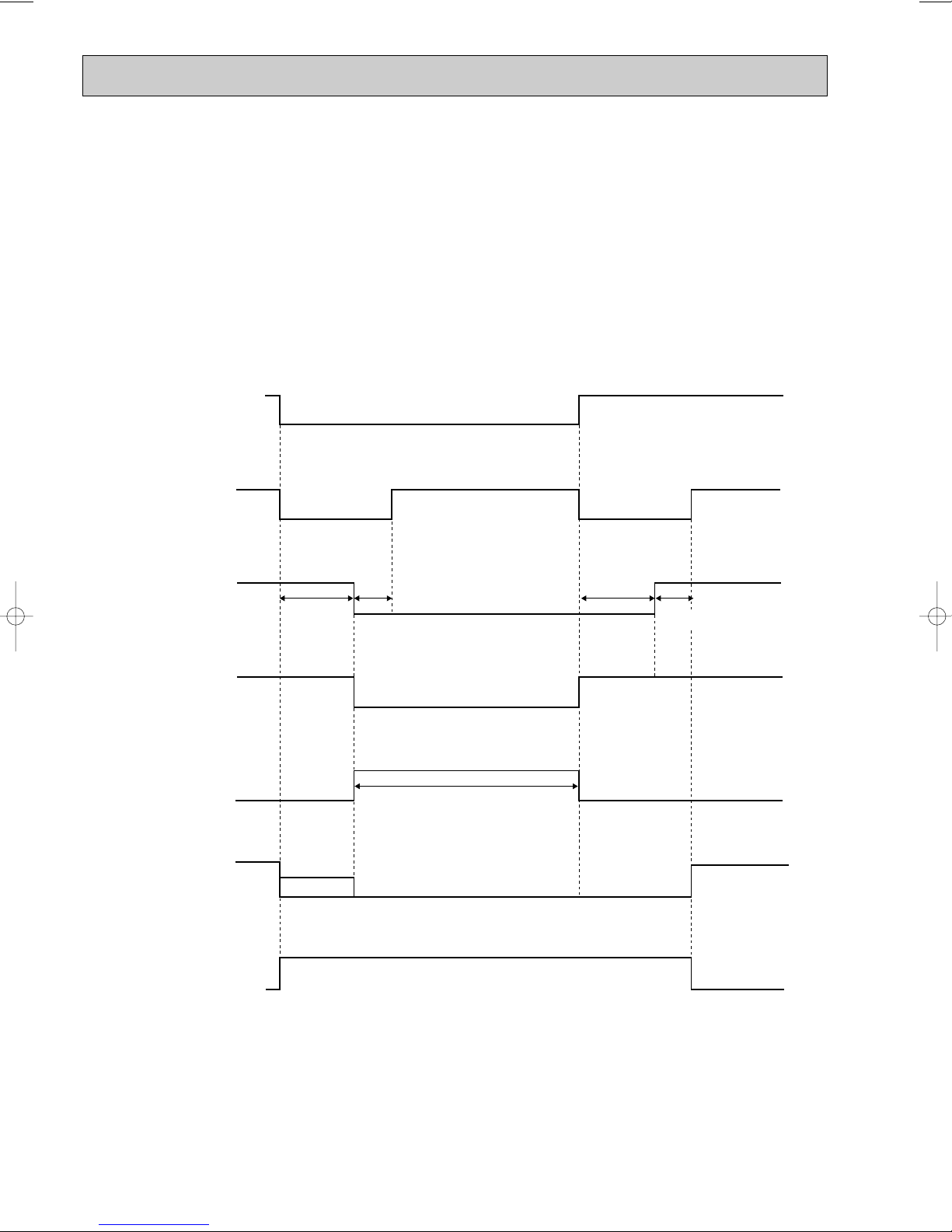
4. Defrosting <MUH-A07/A09/A12WV>
Defrosting of outdoor heat exchanger is controlled by DEICER P.C. board, with detection by the defrost thermistor RT61.
(1) Starting conditions of defrost
When all conditions of a) ~ c) are satisfied, the defrosting operation starts.
a) The compressor cumulative operation time exceeds 40 minutes without the defrosting operation working.
b) RT61 reads - 3°C or less.
c) After releasing the high pressure protection 4 minutes and 15 seconds have elapsed.
(2) Releasing conditions of defrost
When the condition d) or e) is satisfied, the defrosting operation stops.
d) RT61 reads 3.1°C or more.
e) The defrosting time exceeds 10 minutes.
Operation time chart
Example
Defrost thermistor RT61
3.1: or more
-3: or less
Outdoor 52C
contactor
(Compressor)
ON
OFF
X62
(R.V. coil)
ON
OFF
30 sec.
15 sec.
30 sec.
5 sec.
SR61
Outdoor fan
Defrost
counter
Indoor fan
ON
OFF
ON
OFF
ON
Very Low
❈
Max 10 min.
NOTE
OFF
Indoor
Horizontal
Horizontal vane
Set position
NOTE ● When the indoor coil thermistor RT12 reads above 0°C, indoor fan operates at Very Low for 30 seconds.
● When the indoor coil thermistor RT12 reads 0°C or less, the indoor fan stops.
88
Page 89

5. R.V. coil control <MUH-A07/A09/A12WV>
Mode
COOL mode of
"I FEEL CONTROL"
DRY mode of
"I FEEL CONTROL"
HEAT mode of
"I FEEL CONTROL"
Initial room temperature
MUH type
25: or more
23:or more,
less than 25:
less than 23:
MU&MUX type
25: or more
more than13:,
less than 25:
Heating · · · · · ON
Cooling · · · · · OFF
Dry · · · · · · · · OFF
When operation starts, the 4-way valve reverses for 5 seconds right before start-up of the compressor.
Operation time chart
(COOL/DRY)
5 sec.
(HEAT)
5 sec.
Compressor
R.V. coil
Outdoor fan
ON
OFF
ON
OFF
ON
OFF
ON
OFF
ON
OFF
ON
OFF
11-5. “I FEEL CONTROL” ( ) OPERATION
(1) Press OPERATE/STOP(ON/OFF) button.
OPERATION INDICATOR lamp of the indoor unit turns on
with a beep tone.
(2) Select “I FEEL CONTROL”( ) mode with the OPERA-
TION SELECT button.
(3) The operation mode is determined by the initial room tem-
perature at start-up of the operation, as shown on the
right table.
● Once the mode is fixed, the mode does not change by room temperature afterwards.
● Under the ON-TIMER ( ) operation, mode is determined according to the room temperature at set time the opera-
tion starts.
● When the system is stopped on the remote controller and restarted within 2 hours in “I FEEL CONTROL” ( ) mode,
the system operates in previous mode automatically regardless of the room temperature.
Operation time chart
Example
Previous operation
COOL mode of
“I FEEL CONTROL”
or COOL mode
Restart
COOL mode of
“I FEEL CONTROL”
When the system is restarted after 2 hours and more, the operation mode is determined by the room temperature at
start-up of the operation.
Operation time chart
Example
Previous operation
COOL mode of
“I FEEL CONTROL”
or COOL mode
Restart
COOL or DRY or
HEAT mode of “I FEEL
CONTROL” that determined by room temperature at start-up of
the operation.
89
Page 90

Mode
COOL mode of
"I FEEL CONTROL"
DRY mode of
"I FEEL CONTROL"
HEAT mode of
"I FEEL CONTROL"
Initial room temperature
Initial set temperature
26:
26: or more
25: or more,
less than 26:
23: or more,
less than25:
24:
Initial room temperature
minus 2:
Initial room temperature
minus 2:
❈1
more than 13:,
less than 25:
26: or more
25: or more,
less than 26:
less than 23:
MU & MUX type
MUH type
(4) The initial set temperature is decided by the initial room temperature.
TOO
COOL
TOO
WARM
❈1 When the system is restarted with the remote controller, the system operates with the previous set temperature regard-
less of the room temperature at restart.
(5) TEMPERATURES buttons
In “I FEEL CONTROL” ( ) mode, set temperature is decided by the microprocessor based on the room temperature.
In addition, set temperature can be controlled by TOO WARM or TOO COOL buttons when you feel too cool or too
warm. Each time the TOO WARM or TOO COOLbutton is pressed, the indoor unit receives the signal and emits a beep
tone.
● Fuzzy control
When the TOO COOL or TOO WARM button is pressed, the microprocessor changes the set temperature, considering
the room temperature, the frequency of pressing TOO COOL or TOO WARM button and the user’s preference to heat or
cool. So this is called “Fuzzy control”, and works only in “I FEEL CONTROL” mode.
In DRY mode of “I FEEL CONTROL”, the set temperature doesn’t change.
…
To raise the set temperature 1~2 degrees(°C)
…
To lower the set temperature 1~2 degrees(°C)
11-5-1. COOL mode of “I FEEL CONTROL”
1. Thermostat control
Thermostat control is as same as COOL OPERATION.(11-1.1.)
2. Indoor fan speed control
Indoor fan speed control is as same as COOL OPERATION.(11-1.2.)
3. Coil frost prevention
Coil frost prevention is as same as COOL OPERATION.(11-1.3.)
11-5-2. DRY mode of “I FEEL CONTROL”
1. Thermostat control
Thermostat control is as same as DRY OPERATION.(11-2.1.)
2. Indoor fan speed control
Indoor fan speed control is as same as DRY OPERATION.(11-2.2.)
3. The operation of the compressor and indoor/outdoor fan
The operation of the compressor and indoor/outdoor fan is as same as DRY OPERATION.(11-2.3.)
4. Coil frost prevention
Coil frost prevention is as same as DRY OPERATION.(11-2.4.)
11-5-3. HEAT mode of “I FEEL CONTROL” <MUH-A07/A09/A12WV>
1. Thermostat control
Thermostat control is as same as HEAT OPERATION.(11-4.1.)
2. Indoor fan speed control
Indoor fan speed control is as same as HEAT OPERATION.(11-4.2.)
3. High pressure protection
High pressure protection is as same as HEAT OPERATION.(11-4.3.)
4. Defrosting
Defrosting is as same as HEAT OPERATION.(11-4.4.)
5. R.V. coil control
R.V. coil control is as same as HEAT OPERATION.(11-4.5.)
90
Page 91

11-6. FAN MOTOR CONTROL
(1) Rotational frequency feedback control
The indoor fan motor is equipped with a rotational frequency sensor, and outputs signal to the microprocessor to
feedback the rotational frequency. Comparing the current rotational frequency with the target rotational
frequency (High,Med.,Low), the microprocessor controls SR141 and adjusts fan motor electric current to make the
current rotational frequency close to the target rotational frequency. With this control, when the fan speed is switched,
the rotational frequency changes smoothly.
High High
Med.
Low
(2) Fan motor lock-up protection
When the rotational frequency feedback signal is not output for 12 seconds, (or when the microprocessor cannot detect
the signal for 12 seconds) the fan motor is regarded locked-up. Then the electric current to the fan motor is shut off. 3 minutes later, the electric current is applied to the fan motor again. During the fan motor lock-up, the OPERATION INDICATOR lamp flashes on and off to show the fan motor abnormality. (Refer to page 109.)
11-7. AUTO VANE OPERATION
(1) Vane motor drive
These models are equipped with a stepping motor for the horizontal vane. The rotating direction, speed, and angle of
the motor are controlled by pulse signals (approx. 12V) transmitted from indoor microprocessor.
(2) The horizontal vane angle and mode changes as follows by pressing the VANE CONTROL button.
(3) Positioning
The vane is once pressed to the vane stopper below to confirm the standard position and then set to the desired angle.
Confirming of standard position is performed in case of follows.
(a) When the OPERATE/STOP(ON/OFF) button is pressed.
(b) When the vane control is changed from AUTO to MANUAL.
(c) When the SWING is finished.
(d) When the test run starts.
(e) When the power supply turns ON.
(4) VANE AUTO ( ) mode
In VANE AUTO mode, the microprocessor automatically determines the vane angle to make the optimum room-temperature distribution.
1 In COOL and DRY operation
Vane angle is fixed to Angle 1.
2 In FAN operation <MU-A07/A09/A12WV>
2 In HEAT operation
(5) Dew prevention
During COOL or DRY operation at Vane Angle 4 or 5 when the cumulative operation time of compressor exceeds 1
hour, the vane angle automatically changes to Angle 1 for dew prevention.
(6) SWING MODE ( )
By selecting SWING mode with the VANE CONTROLbutton, the horizontal vane swings vertically. The remote controller
displays “ ”.
<MUH-A07/A09/A12WV>
Vane angle is fixed to Angle 4.
91
Page 92

(7) Cold air prevention in HEAT operation
Set position
Angle 1
Released
Cold air prevention
24:
28:
When any of the following conditions occurs in HEAT operation, the horizontal vane angle changes to Angle 1 automatically to prevent cold air blowing on users.
① Compressor is not operating.
➁ Defrosting is performed.
➂ Indoor coil thermistor RT12 reads 24: or below.
➃ Indoor coil thermistor RT12 temperature is raising from 24°C or below, but it does not exceed 28:.
Indoor coil thermistor
RT12 temperature
NOTE : If the temperature of RT12 reads from 24°C to 28°C at the air conditioner stating , this control works.
(8) ECONO COOL ( ) operation (ECONOmical operation)
When the ECONO COOL button is pressed in COOL mode, set temperature is automatically set 2°C higher than that in
COOL mode.
Also the horizontal vane swings in various cycle according to the temperature of indoor heat exchanger(RT12).
SWING operation makes you feel cooler than set temperature. So, even though the set temperature is higher than that
in COOL mode, the air conditioner can keep comfort. As a result, energy can be saved.
ECONO COOL operation is cancelled when the ECONO COOL button is pressed once again or VANE CONTROL button is pressed or operation mode is changed.
NOTE : ECONO COOL operation does not work in COOL mode of “I FEEL CONTROL”.
SWING operation
In swing operation of ECONO COOL operation mode, the initial air flow direction is adjusted to “Horizontal”.
According to the temperature of indoor coil thermistor RT12 at starting of this operation, next downward blow time is
decided. Then when the downward blow has been finished, next upward blow time is decided.
For initial 10 min. the swing operation is performed in table G~H for quick cooling.
Also, after 10 min. when the difference of set temperature and room temperature is more than 2 degrees, the swing
operation is performed in table D~H for more cooling.
The air conditioner repeats the swing operation in various cycle as follows.
<MUH-A07/A09/A12WV>
Horizontal vane
Temperature of indoor
coil thermistor RT12
A
B
C
D
E
F
G
H
15°C or less
15°C to 17°C
17°C to 18°C
18°C to 20°C
20°C to 21°C
21°C to 22°C
22°C to 24°C
more than 24°C
Downward blow time
(sec.)
2
5
8
11
14
17
20
23
Horizontal blow time
(sec.)
23
20
17
14
11
8
5
2
11-8. TIMER OPERATION
1. How to set the timer
(1) Press OPERATE/STOP(ON/OFF) button to start the air conditioner.
(2) Check that the current time is set correctly.
NOTE : Timer operation will not work without setting the current time. Initially “AM0:00” blinks at the current time display
of TIME MONITOR, so set the current time correctly with CLOCK SET button.
(3) Press ON or OFF TIMER buttons to select the operation.
“ ” button... AUTO START operation (ON timer)
“ ” button... AUTO STOP operation (OFF timer)
92
Page 93

PM
AM
PM
PM
(4) Press HR. and MIN. button to set the timer. Time setting is 10-minute units.
HR. and MIN. button will work when “ ” or “ ” mark is flashing.
These marks disappear in 1 minute.
After setting the ON timer, check that OPERATION INDICATOR lamp of the indoor unit lights.
NOTE1 : Be sure to place the remote controller at the position where its signal can reach the air conditioner even during
TIMER operation, or the set time may deviate within the range of about 10 minutes.
NOTE2 : Reset the timer in the following cases, or the set time may deviate and other malfunctions may occur.
● A power failure occurs.
● The circuit breaker functions.
2. Cancel
TIMER setting can be cancelled with the ON or OFF TIMER buttons. (“ ” or “ ”)
To cancel the ON timer, press the “ ” button.
To cancel the OFF timer, press the “ ” button.
TIMER is cancelled and the display of set time disappears.
PROGRAM TIMER
● The OFF timer and ON timer can be used in combination.
● “ ” and “ ” display shows the order of the OFF timer and ON timer operation.
(Example 1) The current time is 8:00 PM.
The unit turns off at 11:00 PM, and on at 6:00 AM.
(Example 2) The current time is 11:00 AM.
The unit turns on at 5:00 PM, and off at 9:00 PM.
NOTE : TIMER setting will be cancelled by power failure or breaker functioning.
11-9. EMERGENCY-TEST OPERATION
In case of test run operation or emergency operation, use the EMERGENCY OPERATION switch on the front of the
indoor unit. Emergency operation is available when the remote controller is missing, has failed or the batteries of remote
controller run down. The unit will start and the OPERATION INDICATOR lamp will light.
The first 30 minutes of operation is the test run operation. This operation is for servicing. The indoor fan speed runs at
High speed and the system is in continuous operation. (The thermostat is ON.)
After 30 minutes of test run operation the system shifts to EMERGENCY COOL [/HEAT <MUH-A07/A09/A12WV,
MXZ-A18WV>] MODE with a set temperature of 24°C. The fan speed shifts to Med. speed.
The coil frost prevention works even in emergency operation [, and defrosting <MUH-A07/A09/A12WV, MXZ-A18WV>
too].
In the test run or emergency operation, the horizontal vane operates in VANE AUTO ( ) mode.
Emergency operation continues until the EMERGENCY OPERATION switch is pressed once again (MU-A07/A09/A12WV,
MUX-A10/A19/A20/A25/A26WV)/once or twice (MUH-A07/A09/A12WV, MXZ-A18WV) or the unit receives any signal
from the remote controller. In case of latter normal operation will start.
NOTE : Do not press the EMERGENCY OPERATION switch during normal operation.
EMERGENCY OPERATION switch
93
• The following indication does not depend on the
shape of lamp.
OPERATION INDICATOR lamp
Press once <Cool>
Press again <Heat>
Press once again <Stop>
w Heat is available only in MUH-A07/A09/A12WV and
MXZ-A18WV.
Page 94

11-10. OUTDOOR UNIT ACTUATOR CONTROL
ACTUATOR
ON
OFF
ON
OFF
ON
OFF
ON (OPEN)
OFF (CLOSE)
ON (OPEN)
OFF (CLOSE)
ON (OPEN)
OFF (CLOSE)
ON (OPEN)
OFF (CLOSE)
ON (CLOSE)
OFF (OPEN)
ON (CLOSE)
OFF (OPEN)
SOLENOID
VALVE
MUX-A26WV -
E1
INDOOR UNIT
MC1
MC2
MF61
21R1
21R2
21R3
21R4
21RA
(BALANCE)
21RB
(BALANCE)
COMPRESSOR
OUTDOOR
FAN MOTOR
A
ON
ON
OFF
OFF
–
–
–
–
OFF
ON
OFF
–
–
–
–
–
–
ON
ON
OFF
OFF
–
–
–
–
B
ON
OFF
ON
OFF
–
–
–
–
ANY UNIT ON
OFF
–
–
ON
OFF
–
–
–
–
ON
OFF
ON
OFF
–
–
–
–
C
–
–
–
–
ON
ON
OFF
OFF
OFF
–
–
–
–
ON
OFF
–
–
–
–
–
–
ON
ON
OFF
OFF
D
–
–
–
–
ON
OFF
ON
OFF
OFF
–
–
–
–
–
–
ON
OFF
–
–
–
–
ON
OFF
ON
OFF
ACTUATOR
ON
OFF
ON
OFF
ON
OFF
ON (OPEN)
OFF (CLOSE)
ON (OPEN)
OFF (CLOSE)
ON (CLOSE)
OFF (OPEN)
SOLENOID
VALVE
MUX-A20WV -
E1
INDOOR UNIT
MC1
MC2
MF61
21R3
21R4
21RB
COMPRESSOR
OUTDOOR
FAN MOTOR
A
ON
OFF
–
–
–
–
OFF
–
–
–
–
–
–
–
–
B
–
–
ON
ON
OFF
OFF
ANY UNIT ON
OFF
ON
OFF
–
–
ON
ON
OFF
OFF
C
–
–
ON
OFF
ON
OFF
OFF
–
–
ON
OFF
ON
OFF
ON
OFF
ACTUATOR
ON
OFF
ON
OFF
ON (CLOSE)
OFF (OPEN)
ON (OPEN)
OFF (CLOSE)
ON (OPEN)
OFF (CLOSE)
SOLENOID
VALVE
MUX-A10WV - E1
INDOOR UNIT
MC
MF61
21R
(BALANCE)
21R1
21R2
COMPRESSOR
OUTDOOR
FAN MOTOR
A
ON
ON
OFF
OFF
ANY UNIT ON
OFF
ON
ON
OFF
OFF
ON
OFF
–
–
B
ON
OFF
ON
OFF
OFF
ON
OFF
ON
OFF
–
–
ON
OFF
ACTUATOR
ON
OFF
ON
OFF
ON
OFF
MUX-A19WV -
E1 MUX-A25WV - E1
INDOOR UNIT
MC1
MC2
MF61
COMPRESSOR
OUTDOOR
FAN MOTOR
A
ON
OFF
–
–
ANY UNIT ON
OFF
B
–
–
ON
OFF
OFF
“–” means that the indoor unit is not related to the control of actuator.
94
Page 95

11-11 INVERTER MULTI SYSTEM CONTROL
MXZ-18WV -
Indoor unit
microprocessor
E1
Outdoor unit control microprocessor
SSR61
Compressor
power
factor
Drive
circuit
Transistor
module
Fin temperature
thermistor RT65
Comp.
Discharge
temperature
thermistor
RT61
Compressor
primary
current
Output signal
Input signal
Compressor
secondary
current
x 61
x 62
Indoor Unit
Indoor Unit
Indoor Unit
Indoor Unit
Gas pipe
temperature
thermistor RT6B
R. V. coil
21S4
B
Highpressure protect
Gas pipe
A
temperature
thermistor RT6A
Evaporation
temperature
thermistor
RT63
thermistor RT68
Outdoor
fan motor
MF61
LEV (A)
A
LEV (B)
Defrost
thermistor
RT62
B
95
Page 96

11-11-2. Outline of main power supply circuit
1. At the start of operation
Rush current is generated the instant the electricity is turned on to the main power
supply circuit to operate the compressor.
To prevent the rush current from running into the main power supply circuit, R64A, R64B (Current-limiting resistor) absorbs
the rush current.
After the rush current is absorbed, X64 (Relay) is ON and the circuit to R is
short-circuited, then the electricity to R is bypassed.
When X64 is ON, the system starts the operation of compressor.
2. At normal operation
The noise of alternating current of power supply is eliminated by L61, L62 (Common mode choke coil).
Then DS61, DS62 (Diode stack) performs full-wave rectification of alternating current and the
alternating current is converted to direct current.
C61, C62 and C63 (Smoothing capacitor) stabilizes the power supply converted to direct current from alternating current
and supplies it to IPM (Intelligent power module).
Direct current rectified by DS61, DS62 is converted to three-phase alternating current by IPM.
Microcomputer installed in the electronic control P.C. board controls frequency and voltage of three-phase alternating
current converted by IPM.
Three-phase alternating current is supplied from IPM to the compressor with frequency and voltage decided by
microcomputer based on various kinds of information.
CT61, CT761 (Current transformer) measures the current of main power supply circuit.
3. Power-factor improvement of power supply and harmonics control
Although C61, C62, and C63 [smoothing capacitor] are used in this inverter circuit in order to supply direct-current stably,
since the charge current to a capacitor turns into intermittent current in the stable circuit with only a capacitor, power factor
of power supply gets worse and harmonics ingredient also becomes large.
Then, AFM [active filter module] and L [reactor] have been arranged on direct-current circuit, and the improvement of
power factor and generating of harmonics are controlled by bringing the intermittent current waveform of alternating
power supply close to sine wave synchronized with the power supply voltage waveform. (Note 1)
Note 1: When short-circuited between plus and minus pole of direct-current circuit,
alternating power supply current flows. By controlling time of short-circuiting to flow proper amount of current in the
intermittent portion of alternating power supply current constantly, the current waveform of alternating power supply is
brought close to sine wave.
4. Removal of electric noise
Because of the noise filter circuit formed by L61 and L62 [CMC coil] and the capacitor on the noise filter board, the electric
noise of the alternating power supply supplied to the main power supply circuit is removed.
Moreover, common mode noise is absorbed with the above-mentioned noise filter, and the normal mode noise is
absorbed in the noise filter circuit formed by L63 [NMC coil] and the capacitors [C650A, C650B, and C650C] on the
control board so that the electric noise generated in the inverter circuit may not leak out.
POWER
SUPPLY
X64
R64A/R64B
DS61/DS62 AFM
L
L61/L62
L
N
U
U
V
V
W
W
P
N
NOISE FILTER
P.C.BOARD
ELECTRONIC CONTROL P.C. BOARD
CT61 L63
CT761
+
+
-
MC
IPM
11-11-1. INVERTER MAIN POWER SUPPLY CIRCUIT
96
Page 97

5. IPM
Target power factor minus detected power factor
(Calculated value is supposed to be "A".)
Calculation of voltage
correction value (%)
A[-2%
-2%<A<+2%
A]+2%
Previous voltage correction value minus 1
Same as previous voltage correction value
Previous voltage correction value plus 1
1 slip 0
Power factor
efficiency
Six power transistors that outputs the direct current waveform as three-phase alternating current waveform, the driving
circuit which operates the power transistors, and the overcurrent detecting circuit which protects the power transistors are
built into the IPM. It can simplify and miniaturize the control circuit.
6.AFM [Active Filter Module]
The circuit that detects power supply voltage waveform, the circuit that detects the current flowing in module, the switching
element that short-circuits between plus and minus pole of direct-current circuit, and the switching element driving current
are built into AFM.
The current waveform is automatically adjusted by controlling the interval of short-circuit between plus and minus pole of
direct-current circuit so that the waveform of actual current flowing to service power supply is synchronized with the phase
of power supply voltage waveform detected by AFM.
11-11-3. Function of main parts
SYMBOL
C61,C62, C63
CT61, CT761
DS61, DS62
IPM
L
L61, L62
L63
R
X64
NAME
SMOOTHING CAPACITOR
CURRENT TRANSFORMER
DIODE STACK
INTELLIGENT POWER MODULE
REACTOR
COMMON MODE CHOKE COIL
NORMAL MODE CH6KE COIL
CURRENT-LIMITING RESISTOR
RELAY
FUNCTION
It stabilizes the direct current voltage.
It measures the current of main power supply circuit.
It converts the alternating current voltage to direct current voltage.
It generates three-phase alternating current and operates compressor.
It is combined with DS62 to improve the power factor of power supply.
It eliminates and absorbs the electrical noise.
It absorbs the rush current not to run into the main power supply
when the electricity is turned on.
It short-circuits the circuit to current-limiting resistor when the
compressor operates.
circuit
11-12. Optimal voltage control
The purpose of optimal voltage control is to operate the compressor at optimal
voltage that meets the load detected by the power factor of the compressor.
1. Optimal
As shown on the right the efficiency (ratio of output against input) of the
motor in the compressor becomes optimal when the sliding (ratio of difference between the actual number of rotation and the number of synchronous
rotation of motor) is one fixed value. The value of sliding can be calculated
from the power factor since the sliding and the power factor are mutually
related as shown in the table on the right. To make the value of sliding so
that the efficiency of motor is optimal, the power factor of the compressor is
detected. Then the detected power factor is controlled so that its efficiency
can be high. As a result, it is possible to operate the compressor at optimal
voltage.
2. How to determine the optimal voltage
Compare the detected power factor with the target power factor so that the efficiency of motor is optimal, the voltage
correction value is changed and the optimal output voltage is determined.
Optimal output voltage[V]= Standard voltage at certain frequency [V]x voltage correction value(%)
97
Page 98

11-13 LEV control
Linear expansion valve (LEV) is controlled by "Thermostat ON" commands given from each unit.
Indoor unit status
Stop of all indoor unit
When outdoor unit is operating,
some indoor units stop and
some operate.
Thermostat OFF in
COOL or DRY mode
When the outdoor unit operates (When the other indoor unit operates): 5 pulse.
When outdoor unit stops. (When the other indoor unit stops or thermo off):
Maintain LEV opening before stop ➝ 500 pulse in 15 minutes
Opening before stop ➝ 500 pulse in 15 minutes
• LEV opening for each indoor unit is determined by adding adjustment in accordance
with the number of operating unit and the capacity class to standard opening, based
on the operation frequency:
Ex.) Opening 130 pulse in standard opening 1 ➝ Minimum 80 pulse, Maximum 205
Thermostat ON in
COOL or DRY mode
pulse. (Capacity code 4 at 1 unit operation) (Capacity code 1 at 4 units operation)
• After starting operation, adjustment in accordance with intake super heat, discharge
temperature is included in standard opening. w1
Note: LEV opening in each frequency at DRY operation and COOL operation is the
same. However, velocity and compressor operation frequency controls are
different. See 11-2 Operational frequency range
(As far as the indoor unit velocity control goes, refer to DRY operation in
MICROPROCESSOR CONTROL in the indoor unit service manual.)
• When the outdoor unit operates. (When the other indoor unit operates): 59 pulse
Thermostat OFF in HEAT mode
• When the outdoor unit stops. (When the other indoor unit stops or thermo off):
Maintain LEV opening before stop ➝ 500 pulse in 15 minutes.
• LEV opening for each indoor unit is determined by adding adjustment in accordance
with the number of operating unit and the capacity class to standard opening, based
Thermostat ON in HEAT mode
on the operation frequency:
Ex.) Opening 120 pulse in standard opening 1 ➝ Minimum 70 pulse, Maximum 165
pulse. (Capacity code 4 at 1 unit operation) (Capacity code 1 at 4 units operation)
• After starting operation, opening becomes the one that adjustment in accordance
with discharge temperature was added to basic opening. w1
w1 LEV opening when the outdoor unit is operating: Upper limit 500 pulse, Lower limit 59 pulse.
LEV opening
COOL : 5 pulse (full closed)
HEAT : 59 pulse (slightly opened)
Determination of LEV standard opening in each indoor unit
• The standard opening is on the straight line, which connects an each standard point in the section where divided
into seven according to the operation frequency of compressor as shown in the figure below.
(LEV opening is controlled in proportion to the operation frequency.)
Note: Opening is adjusted at the standard opening according to the indoor unit conditions.
However, inclination of standard opening in each point of opening does not change with the original curve.
• Add opening provided in Difference in Capacity in the table below to the standard opening from 1 to 8,
when capacity of the indoor unit is excluding code 1.
• Add opening provided in Difference in Operation number in the table below to determined LEV opening for
each indoor unit, when 2, 3 or 4 indoor units are operated at the same time.
Note: Even when the adjusted standard opening exceeds the driving range from 59 to 500 pulse, actual
driving output opening is in a range from 59 to 500 pulse.
< Calculation example of LEV opening >
Cool operation: Compressor frequency 70Hz: 2 units ON: 18 class
(170-150)p(80-60)o(70-60)+150+75-30=205 pulse
Standard opening
12345678
220
210
200
190
180
170
160
150
140
LEV opening (Pulse)
130
120
7 20 40 60 80 100 120 140
Operation frequency of compressor (Hz) : F
COOL
HEAT
98
Page 99

(1) LEV opening correction by suction super heat (COOL, DRY)
Suction superheat (S.H.)
LEV opening
correction (pulse)
more than 12
10 to12
8 to 10
6 to 8
6 or less
7
5
4
3
0
Superheat
LEV opening
correction (pulse)
more than 9
6 to9
3to 6
6 or less
10
8
4
0
1 Suction super heat
(MIN gas pipe temperature thermistor - Evaporation temperature thermistor)
2 Each correction w 1
• (Each gas pipe temperature thermistor - Evaporation temperature thermistor)
w 1 Perform this, when number of operation units is 2 units or more.
w 2 When the correction opening of suction super heat is 0, correct the LEV opening by discharge temperature.
3 Discharge temperature
COOL DRY HEAT
••
-
•
w 2
•
w 2
•
<Correction>
2
Code3Code2
Standard opening (pulse)
Difference in
capacity
Difference in
operation number
12345678
COOL
HEAT
200
160
210
170
220
180
230
190
Capacity code
Indoor unit
1
07209312418
240
200
240
210
250
210
250
2202520
50
40
-60
-70
(Suction super heat) = (Minimum gas pipe temperature) - (Evaporation temperature)
When COOL and DRY, correct the LEV openings corrected from the table below.
(2) Separate correction (COOL,DRY)
(When number of operation unit is 2 units)
(a) Correction by the separate super heat
Correct the LEV separately by temperature difference between each gas pipe temperature thermistor and evaporator
temperature thermistor.
1 Calculate each super heat of the unit from the expression below;
(Super heat) = (Each gas pipe temperature) - (Minimum gas pipe temperature)
2 Separate correction is performed according to each super heat in the table below.
99
Page 100

(3) LEV opening correction by discharge temperature
Operation frequency
of compressor
Minimum ~ 20
21 ~ 33
34 ~ 46
47 ~ 59
60 ~ 72
73 ~ 85
86 ~ 98
97 ~ 111
111 ~ Maximum
Single
40
40
45
52
62
67
72
75
80
Double
40
40
45
52
62
67
72
75
80
Single
45
50
55
60
65
70
70
75
76
Double
45
50
55
60
65
70
70
75
76
Number of operating unit Number of operating unit
COOL, DRY HEAT
LEV opening correction (pulse)
Discharge temperature (;)
LEV opening
correction (pulse)
More than Target discharge temperature+11
Target discharge temperature+11 to Target discharge temperature+8
Target discharge temperature+8 to Target discharge temperature+5
Target discharge temperature+5 to Target discharge temperature+2
Target discharge temperature+2 to Target discharge temperature-2
Target discharge temperature-2 to Target discharge temperature-5
Target discharge temperature-5 to Target discharge temperature-8
Target discharge temperature-8 to Target discharge temperature-11
Target discharge temperature-11 or less
COOL
10
4
2
1
0
-1
-2
-5
-8
HEAT
8
2
1
1
0
-1
-1
-2
-6
DRY
(Hz)
Min. Max. Rated Min. Max.
Defrost
Rated
Note: When the fan speed of indoor unit is
totally Low notch, the maximum frequency
is rated frequency.
COOL (Hz)
HEAT (Hz)
Number of
operating
unit
1
2
3
2
3
4
5
6
7
25
40
76
90
100
120
55
61
85
110
27
41
53
722543
100
100
122
122
120
120
120
120
72
76
88
120
1
2
capacity
code
When LEV correction output is 0 pulse by the suction super heat at COOL or DRY operation, or HEAT operating, correct
LEV is corrected according to the following table.
The target discharge temperature is determined according to frequency zone and number of operation unit of the
compressor.
Correct the LEV opening according to the difference between target discharge temperature and discharge temperature.
11-14.Operational frequency range
11-15.Heat defrosting control
(1) Conditions to enter defrosting mode
1. When temperature of defrosting thermistor is -3; or less.
2.When specified non-defrosting time, is counted in the control p.c.board is satisfied.
(Total time of compressor operating)
Going to defrosting mode at both condition of 1 and 2.
(2) Defrosting operation
1. Compressor stops for 50 seconds, Indoor fan is off, Defrosting lamp lights.
2.4-way valve reverses flow, Compressor operates by the frequency in heat defrosting control.
3. After compressor stops for 35 seconds, 4-way valve reverses flow, then defrosting finishes.
(3) Conditions to finish defrosting mode
1. When the defrosting thermistor temperature is 13.2; or more.
2. When it has spent 10 minutes for defrosting.
Defrosting finishes at condition of 1 or 2.
100
 Loading...