

Mitsubishi MU-GA20VB, MSC-CA25VB, MUH-GA20VB, MUX-2A28VB, MSC-CB20VB Service Technical Manual
...
SPLIT-TYPE, AIR CONDITIONERS
SPLIT-TYPE, HEAT PUMP AIR CONDITIONERS
FLOOR AND CEILING TYPE AIR CONDITIONERS
FLOOR TYPE, HEAT PUMP AIR CONDITIONERS
Revision D:
• MXZ-5A100VA- has been added.
Please void OBT06 REVISED EDITION-C.
E
No. OBT06
REVISED EDITION-D
SERVICE TECHNICAL GUIDE
Wireless type Models
MSC-CA•VB - · MU-GA•VB MSC-CB•VB - · MUH-GA•VB MSC-GA•VB -
Multi system type Models
E
· MUX-A•VB -
Wireless type Models
MS-GA•VB - · MU-GA•VB MSH-CA•VB MSH-CB•VB -
E
E
MSH-GA•VB - · MUH-GA•VB MSZ-CA•VB - · MUZ-CA•VB MSZ-FA•VA - · MUZ-FA•VA -
· MUZ-FA•VAH -
MSZ-GA•VA - · MUZ-GA•VA -
· MUZ-GA•VAH -
MSZ-CB•VA -
E
MSZ-HA•VA - · MUZ-HA•VA MSZ-GB•VA - · MUZ-GB•VA -
EE
EE
E
EE
EE
EE
EE
E
EE
E
EE
EE
Inverter-controlled multi system type Models
Wireless type Models
MCF-GA•VB
MCFH-GA•VB
MFZ-KA•VA
- · MUCF-GA•VB -
- · MUCFH-GA•VB -
E
-
· MXZ-A•VA -
E
EE
EE
CONTENTS
1. MSC MICROPROCESSOR CONTROL················6
2. MS MICROPROCESSOR CONTROL················15
3. MSH MICROPROCESSOR CONTROL··············26
4. MSZ-CA MICROPROCESSOR CONTROL········39
5. MSZ-FA MICROPROCESSOR CONTROL ········54
6. MSZ-GA, MSZ-CB
MICROPROCESSOR CONTROL ············72
7. MCF MICROPROCESSOR CONTROL············100
8. MCFH MICROPROCESSOR CONTROL·········106
9. MFZ MICROPROCESSOR CONTROL ············115
10. MSZ-HA MICROPROCESSOR CONTROL·····127
11. MSZ-GB MICROPROCESSOR CONTROL·····137
12. MXZ MICROPROCESSOR CONTROL···········150
Revision D: • MXZ-5A100VA- and MXZ-4A80VA- have been added.
E2E
Revision C: • MXZ-2A30VA- and MXZ-2A40VA- have been added.
Revision B: • MSZ-CB•VA- has been added.
• MSZ-HA•VA- has been added.
• MSZ-GB•VA- has been added.
• MXZ-2A40/52VA- has been added.
Revision A: • MFZ-KA•VA - has been added.
E
E
E
E
E
E2E
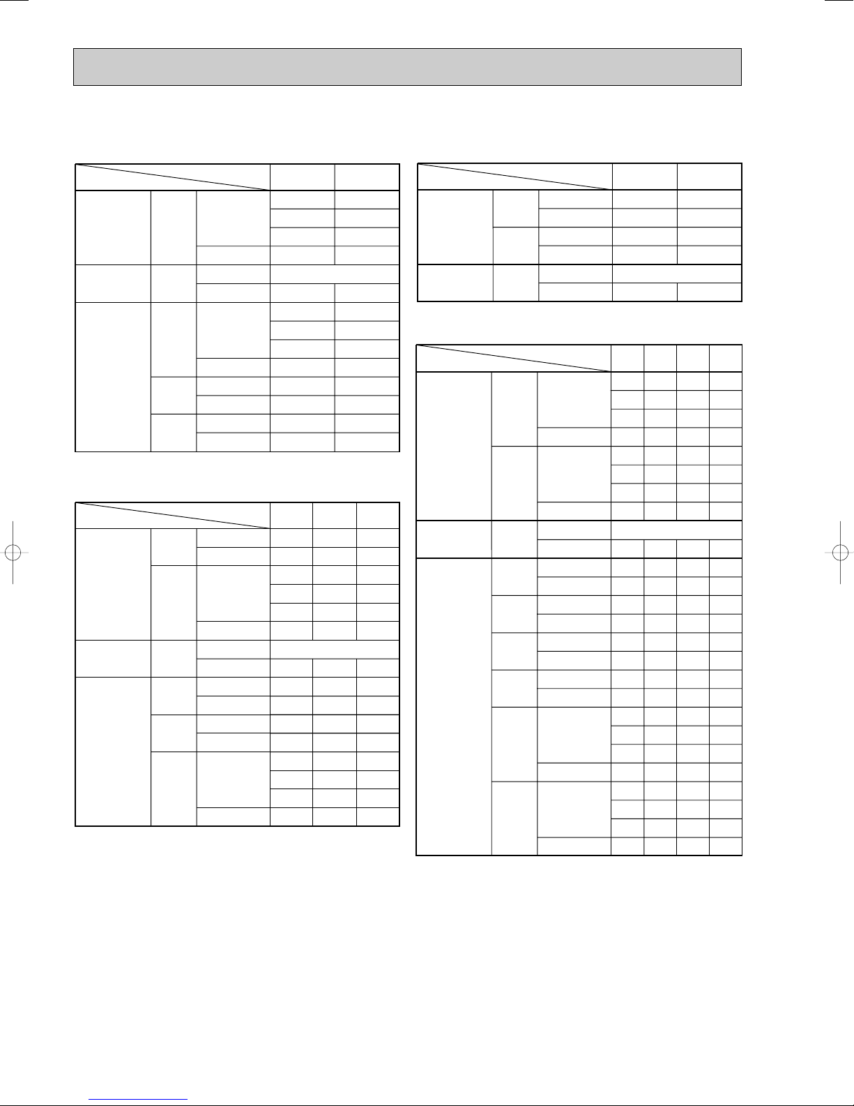
1. MSC MICROPROCESSOR CONTROL·························································6
Indoor unit models Outdoor unit models
MSC-CA20VB MSC-CB20VB MSC-GA20VB MU-GA20VB MUH-GA20VB MUX-2A28VB
MSC-CA25VB MSC-CB25VB MSC-GA25VB MU-GA25VB MUH-GA25VB MUX-2A59VB
MSC-CA35VB MSC-CB35VB MSC-GA35VB MU-GA35VB MUH-GA35VB MUX-3A60VB
MUX-2A70VB
MUX-3A63VB
MUX-4A73VB
1-1. COOL OPERATION················································································6
1-2. DRY OPERATION ··················································································7
1-3. FAN OPERATION ···················································································8
1-4. HEAT OPERATION················································································8
1-5.“I FEEL CONTROL” OPERATION·························································9
1-6. INDOOR FAN MOTOR CONTROL ······················································11
1-7. AUTO VANE OPERATION ···································································11
1-8. TIMER OPERATION·············································································12
1-9. EMERGENCY / TEST OPERATION····················································13
. OUTDOOR UNIT ACTUATOR CONTROL··········································14
1-
10
2. MS MICROPROCESSOR CONTROL ·························································15
Indoor unit models Outdoor unit models
MS-GA50VB MU-GA50VB
MS-GA60VB MU-GA60VB
MS-GA80VB MU-GA80VB
2-1. “I FEEL CONTROL” OPERATION······················································15
2-2. COOL OPERATION··············································································18
2-3. DRY OPERATION ················································································19
2-4. FAN OPERATION ·················································································19
2-5. INDOOR FAN MOTOR CONTROL······················································19
2-6. AUTO VANE OPERATION ···································································19
2-7. TIMER OPERATION·············································································22
2-8. EMERGENCY / TEST OPERATION····················································23
2-9. EXPANSION VALVE CONTROL (LEV CONTROL) ····························24
2-
10.
FUNCTION OF SOFT START RELAY ·················································25
3. MSH MICROPROCESSOR CONTROL·······················································26
Indoor unit models Outdoor unit models
MSH-CA50VB MSH-GA50VB MUH-GA50VB
MSH-CB50VB MSH-GA60VB MUH-GA60VB
MSH-GA80VB MUH-GA80VB
3-1. “I FEEL CONTROL” OPERATION······················································26
3-2. COOL OPERATION··············································································32
3-3. DRY OPERATION ················································································32
3-4. HEAT OPERATION··············································································32
3-5. INDOOR FAN MOTOR CONTROL······················································32
3-6. AUTO VANE OPERATION ···································································33
3-7. TIMER OPERATION·············································································35
3-8. EMERGENCY / TEST OPERATION····················································36
3-9. EXPANSION VALVE CONTROL (LEV CONTROL) ····························37
3-
10.
FUNCTION OF SOFT START RELAY·················································38
2

4. MSZ-CA MICROPROCESSOR CONTROL·················································39
Indoor unit models Outdoor unit models
MSZ-CA25VB MUZ-CA25VB
MSZ-CA35VB MUZ-CA35VB
4-1. “I FEEL CONTROL” OPERATION·····················································39
4-2. AUTO CHANGE OVER ··· AUTO MODE OPERATION······················44
4-3. COOL OPERATION·············································································45
4-4. DRY OPERATION ···············································································45
4-5. HEAT OPERATION·············································································45
4-6. INDOOR FAN MOTOR CONTROL·····················································46
4-7. AUTO VANE OPERATION ··································································46
4-8. TIMER OPERATION············································································47
4-9. EMERGENCY / TEST OPERATION···················································48
4-
10.
INVERTER SYSTEM CONTROL ························································49
11.
OPERATION FREQUENCY CONTROL OF OUTDOOR UNIT··········51
44-
12.
EXPANSION VALVE CONTROL (LEV CONTROL)···························52
5. MSZ-FA MICROPROCESSOR CONTROL ·················································54
Indoor unit models Outdoor unit models
MSZ-FA25VA MUZ-FA25VA MUZ-FA25VAH
MSZ-FA35VA MUZ-FA35VA MUZ-FA35VAH
5-1. COOL OPERATION·············································································55
5-2. DRY OPERATION ···············································································56
5-3. HEAT OPERATION·············································································56
5-4. AUTO CHANGE OVER ··· AUTO MODE OPERATION······················58
5-5. INDOOR FAN MOTOR CONTROL·····················································59
5-6. OUTDOOR FAN MOTOR CONTROL·················································59
5-7. AUTO VANE OPERATION··································································59
5-8. i-see CONTROL OPERATION····························································61
5-9. AREA SETTING ··················································································62
5-10. PLASMA DUO OPERATION ······························································64
. AUTO FRONT PANEL ········································································65
5-
11
5-
12
. TIMER OPERATION ···········································································65
5-13. EMERGENCY / TEST OPERATION···················································66
INVERTER SYSTEM CONTROL ························································67
5-
14.
5-
15.
OPERATIONAL FREQUENCY CONTROL OF OUTDOOR UNIT ·····69
5-
16.
EXPANSION VALVE CONTROL (LEV CONTROL)···························70
6. MSZ-GA, MSZ-CB MICROPROCESSOR CONTROL ································72
Indoor unit models Outdoor unit models
MSZ-GA22VA MSZ-CB22VA
MSZ-GA25VA MSZ-CB25VA MUZ-GA25VA MUZ-GA25VAH
MSZ-GA35VA MSZ-CB35VA MUZ-GA35VA MUZ-GA35VAH
6-1. COOL OPERATION·············································································73
6-2. DRY OPERATION ···············································································74
6-3. HEAT OPERATION·············································································74
6-4. AUTO CHANGE OVER ··· AUTO MODE OPERATION······················76
6-5. INDOOR FAN MOTOR CONTROL·····················································77
6-6. OUTDOOR FAN MOTOR CONTROL·················································77
6-7. AUTO VANE OPERATION··································································77
6-8. TIMER OPERATION············································································79
6-9. EMERGENCY / TEST OPERATION···················································80
6-10.
INVERTER SYSTEM CONTROL·······················································81
11.
OPERATIONAL FREQUENCY CONTROL OF OUTDOOR UNIT ·····83
66-
12.
EXPANSION VALVE CONTROL (LEV CONTROL) ···························84
3

Indoor unit models Outdoor unit models
MSZ-GA50VA MUZ-GA50VA
MSZ-GA60VA MUZ-GA60VA
MSZ-GA71VA MUZ-GA71VA
6-13. COOL OPERATION············································································86
6-14. DRY OPERATION ···············································································87
15
. HEAT OPERATION·············································································88
66-
16
. AUTO CHANGE OVER ··· AUTO MODE OPERATION ·····················90
6-17. INDOOR FAN MOTOR CONTROL·····················································90
18
. OUTDOOR FAN MOTOR CONTROL·················································91
66-
19
. AUTO VANE OPERATION··································································91
6-20. TIMER OPERATION ···········································································94
21
. EMERGENCY/TEST OPERATION·····················································95
66-
22.
INVERTER SYSTEM CONTROL ·······················································95
23.
OPERATIONAL FREQUENCY CONTROL OF OUTDOOR UNIT ·····97
66-
24.
EXPANSION VALVE CONTROL (LEV CONTROL) ···························98
7. MCF MICROPROCESSOR CONTROL·····················································100
Indoor unit models Outdoor unit models
MCF-GA35VB MUCF-GA35VB
MCF-GA50VB MUCF-GA50VB
MCF-GA60VB MUCF-GA60VB
7-1. “I FEEL CONTROL” OPERATION····················································100
7-2. COOL OPERATION············································································103
7-3. DRY OPERATION ··············································································103
7-4. FAN OPERATION ···············································································103
7-5. AUTO VANE OPERATION ·································································103
7-6. TIMER OPERATION···········································································105
7-7. EMERGENCY / TEST OPERATION··················································105
8. MCFH MICROPROCESSOR CONTROL ··················································106
Indoor unit models Outdoor unit models
MCFH-GA35VB MUCFH-GA35VB
MCFH-GA50VB MUCFH-GA50VB
MCFH-GA60VB MUCFH-GA60VB
8-1. “I FEEL CONTROL” OPERATION····················································106
8-2. COOL OPERATION············································································110
8-3. DRY OPERATION···············································································111
8-4. HEAT OPERATION·············································································111
8-5. AUTO VANE OPERATION··································································111
8-6. TIMER OPERATION···········································································113
8-7. EMERGENCY / TEST OPERATION···················································114
9. MFZ MICROPROCESSOR CONTROL······················································115
Indoor unit models
MFZ-KA25VA
MFZ-KA35VA
As for outdoor units SUZ-KA25/35/50VA.TH and SUZKA25/35VAH.TH, refer to service manual OC322.
(
MFZ-KA50VA
9-1. COOL OPERATION···········································································117
9-2. DRY OPERATION··············································································117
9-3. HEAT OPERATION············································································117
9-4. AUTO CHANGE OVER ··· AUTO MODE OPERATION ····················119
9-5. INDOOR FAN MOTOR CONTROL···················································120
9-6. OUTDOOR FAN MOTOR CONTROL···············································120
9-7. AUTO VANE OPERATION································································120
9-8. i-save OPERATION···········································································124
9-9. TIMER OPERATION··········································································125
9-
10.
EMERGENCY / TEST OPERATION·················································126
)
4

10. MSZ-HA MICROPROCESSOR CONTROL·············································127
Indoor unit models Outdoor unit models
MSZ-HA25VA MUZ-HA25VA
MSZ-HA35VA MUZ-HA35VA
10-1. COOL OPERATION·········································································128
10-2. DRY OPERATION ···········································································128
10-3. HEAT OPERATION·········································································129
10-4. INDOOR FAN MOTOR CONTROL·················································130
10-5. AUTO VANE OPERATION······························································131
10-6. TIMER OPERATION········································································133
10-7. EMERGENCY / TEST OPERATION···············································133
10-8. INVERTER SYSTEM CONTROL ····················································134
.
OPERATIONAL FREQUENCY CONTROL OF OUTDOOR UNIT
10-9
11. MSZ-GB MICROPROCESSOR CONTROL·············································137
Indoor unit models Outdoor unit models
······136
MSZ-GB50VA MUZ-GB50VA
11-1. COOL OPERATION·········································································138
11-2. DRY OPERATION············································································139
11-3. HEAT OPERATION··········································································139
11-4. AUTO CHANGE OVER ··· AUTO MODE OPERATION··················141
11-5. INDOOR FAN MOTOR CONTROL ·················································141
11-6. OUTDOOR FAN MOTOR CONTROL ·············································142
11-7. AUT O VANE OPERATION······························································142
11-8. TIMER OPERATION········································································144
11-9. EMERGENCY / TEST OPERATION················································145
11-10.
INVERTER SYSTEM CONTROL ···················································145
11-
11.
OPERATIONAL FREQUENCY CONTROL OF OUTDOOR UNIT
11-
12.
EXPANSION VALVE CONTROL (LEV CONTROL)·······················148
······147
12. MXZ MICROPROCESSOR CONTROL···················································150
Outdoor unit models
MXZ-2A30VA
MXZ-2A40VA
MXZ-2A52VA
MXZ-3A54VA
MXZ-4A71VA
MXZ-4A80VA
MXZ-5A100VA
12-1. INVERTER SYSTEM CONTROL·····················································150
12-2. EXPANSION VALVE CONTROL (LEV CONTROL) ························153
12-3. OPERATIONAL FREQUENCY RANGE···········································159
12-4. HEAT DEFROSTING CONTROL·····················································160
12-5. DISCHARGE TEMPERATURE PROTECTION CONTROL·············161
12-6. REFRIGERANT RECOVERY CONTROL ON HEATING·················161
12-7. OUTDOOR FAN CONTROL·····························································161
12-8. PRE-HEAT CONTROL·····································································162
12-9. COOL OPERATION··········································································162
12-10. DRY OPERATION ············································································163
12-
11
. HEAT OPERATION··········································································163
As for outdoor unit MXZ-8A140VA, refer to service manual
(
OC316.
)
5
1
ON/OFF
FAN
TOO
WARM
TOO
COOL
VANE
MODE
ECONO COOL
STOP
START
HR.
MIN.
I FEEL
COOL
DRY
PM
CLOCK
AM
RESET
CLOCK
HEAT
/FAN
/
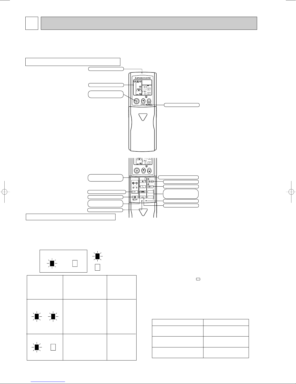
Open the front lid.
ON/OFF
TOO
COOL
PM
AM
TOO
WARM
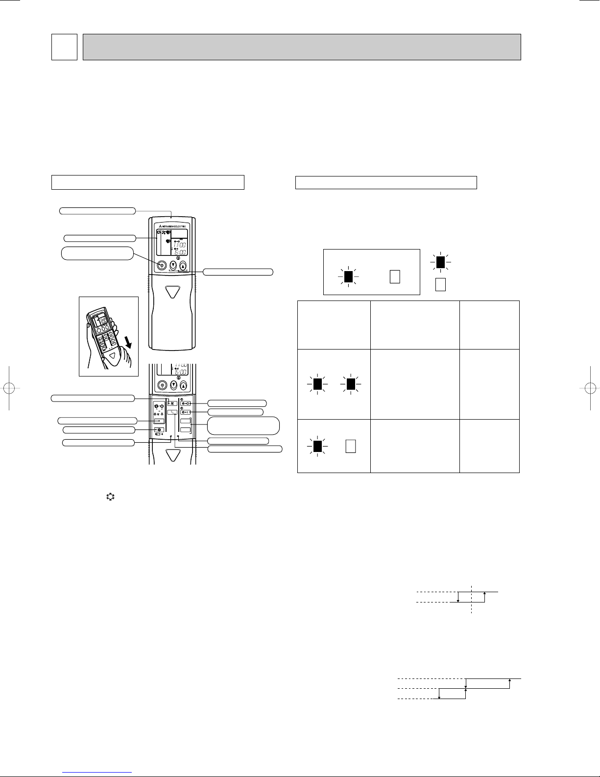
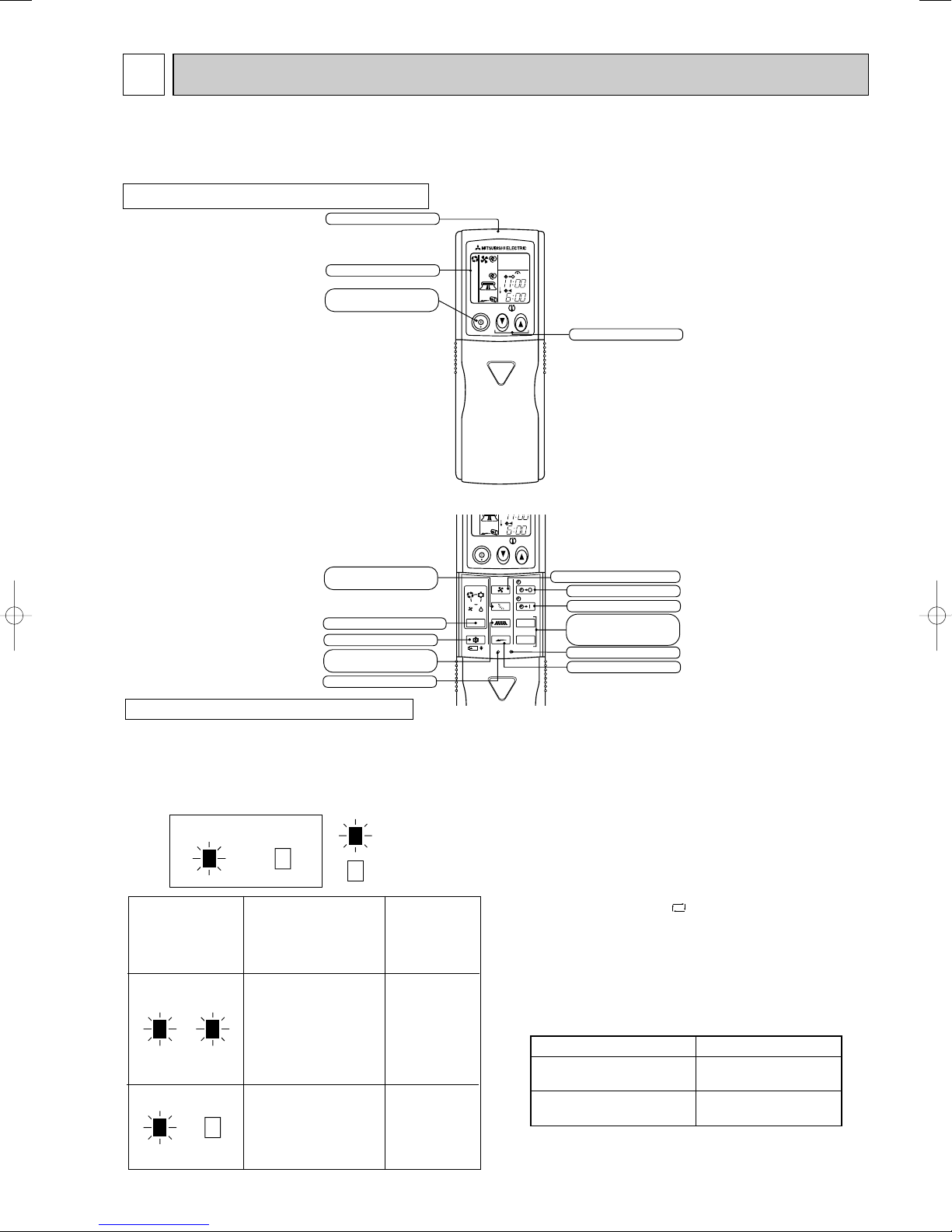
Signal transmitting section
Operation display section
OPERATE /STOP
(ON /OFF) button
TEMPERATURE buttons
OPERATION SELECT button
FAN SPEED CONTROL button
OFF-TIMER button
HR. button
MIN. button
(TIME SET button)
ON-TIMER button
RESET button
ECONO COOL button
VANE CONTROL button
CLOCK SET button
lighted
not lighted
Approx. 2 :
or more
Difference
between target
temperature
and room
temperature
Approx. 2 :
or less
This shows that the
air conditioner is
operating to reach
the target temperature.
Please wait until the
target temperature is
obtained.
This shows that the
room temperature is
approaching the
target temperature.
Operation state
Indication
Operation Indicator
Operation Indicator lamp
The operation indicator at the right side of the indoor
unit indicates the operation state.
INDOOR UNIT DISPLAY SECTION
• The following indication does not
depend on the shape of lamp.
MSC MICROPROCESSOR CONTROL
MSC-CA20VB MSC-CB20VB MSC-GA20VB MU-GA20VB MUH-GA20VB MUX-2A28VB MUX-3A63VB
MSC-CA25VB MSC-CB25VB MSC-GA20VB MU-GA25VB MUH-GA25VB MUX-2A59VB MUX-2A70VB
MSC-CA35VB MSC-CB35VB MSC-GA35VB MU-GA35VB MUH-GA35VB MUX-3A60VB MUX-4A73VB
Once the operation mode is set, the same operation mode can be repeated by simply turning OPERATE/STOP (ON/OFF) button ON. Indoor unit receives the signal with a beep tone.
When the system turns off, 3-minute time delay will operate to protect system from overload and compressor will not restart for
3 minutes.
WIRELESS REMOTE CONTROLLER
1-1. COOL ( ) OPERATION
(1) Press OPERATE/STOP(ON/OFF) button. OPERATION INDICATOR lamp of the indoor unit turns on with a beep tone.
(2) Select COOL mode with OPERATION SELECT button.
(3) Press TEMPERATURE buttons (TOO WARM or TOO COOL button)to select the desired temperature.
The setting range is 16 ~ 31°C
1. Thermostat control
Thermostat is ON or OFF by difference between room temperature and set temperature
Room temperature minus set temperature : 0.3 : or more················································ON
Room temperature minus set temperature : less than -0.3 :············································OFF
2. Indoor fan speed control
Indoor fan operates continuously at the set speed by FAN SPEED CONTROL button regardless
of thermostat’s OFF-ON.
In Auto the fan speed is as follows.
Room temperature minus set temperature : 1.7 : or more·······························High
Room temperature minus set temperature : Between 1 and 1.7 :···················Med.
Room temperature minus set temperature : less than 1 :·································Low
Initial temperature difference Thermostat
Initial temperature difference
Fan speed
6
Difference between room
temperature and set temperature during operation
Set temperature
-0.3 :
0.3 :
Difference between room
temperature and set temperature during operation
3 :
1.7 :
1 :
35
30
25
20
15
10
:
10 15 20 25 30 35
Set temperature
Initial room temperature
Set temperature and
initial room temperature in dry mode
:
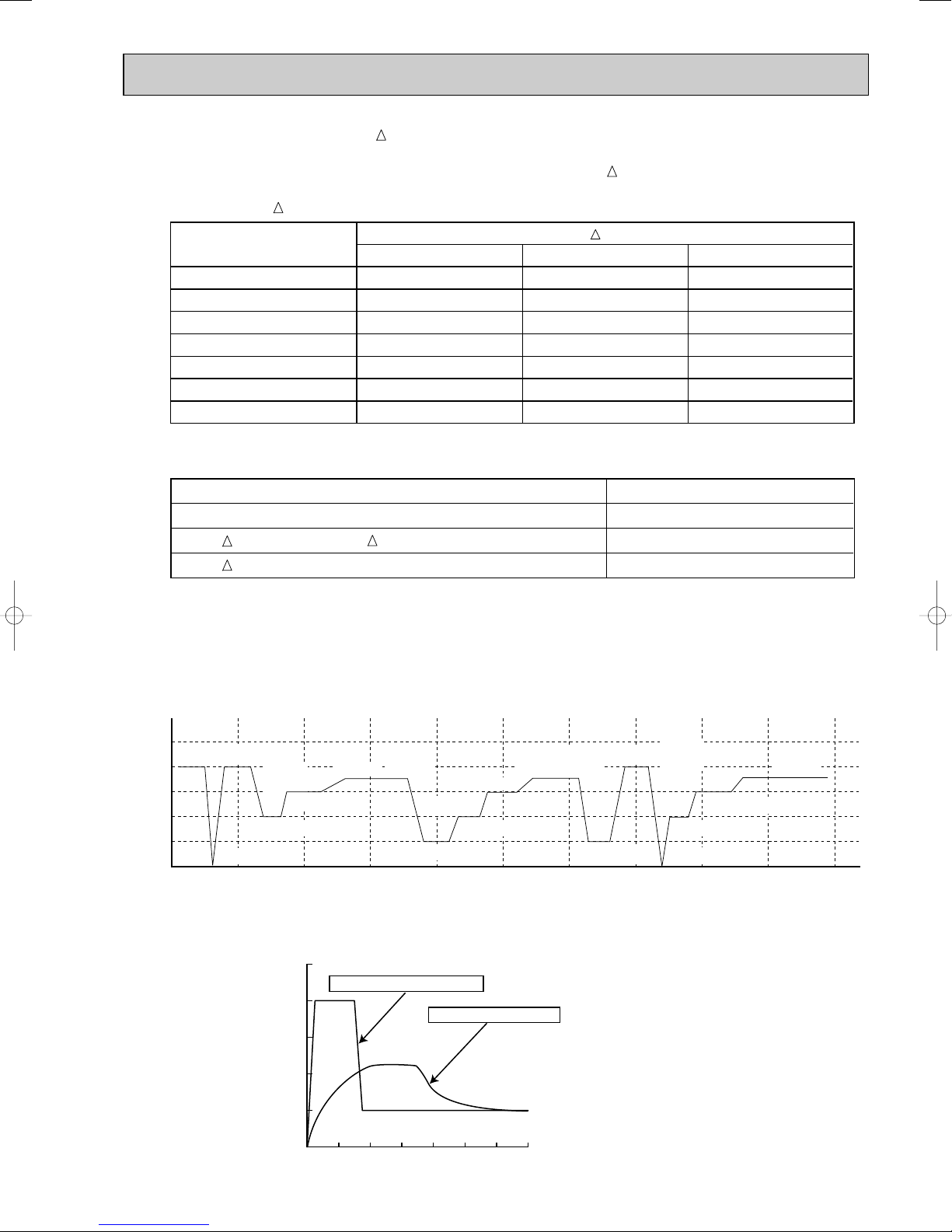
3. Coil frost prevention
① Temperature control
When the indoor coil thermistor RT12 reads 4°C or below(MSC-CA20/CA25/CB20/CB25/GA20/GA25VB) / 0°C or
below(MSC-CA35/CB35/GA35VB) for 5 minutes, the coil frost prevention mode starts.
The indoor fan operates at the set speed and the compressor stops for 5 minutes.
After that, if RT12 still reads below 4°C (MSC-CA20/CA25/CB20/CB25/GA20/GA25VB) / 0°C (MSC-CA35/CB35/GA35VB),
this mode is prolonged until RT12 reads over 4°C (MSC-CA20/CA25/CB20/CB25/GA20/GA25VB) / 0°C (MSCCA35/CB35/GA35VB).
② Time control
When the three conditions as follows have been satisfied for 1 hour and 45 minutes, the compressor stops for 3 minutes.
The indoor fan operates at the set speed.
a. Compressor has been continuously operating.
b. Indoor fan speed is Low or Med.
c. Room temperature is below 26°C.
When compressor stops, the accumulated time is cancelled. When compressor restarts, time counting starts
from the beginning.
Time counting also stops temporarily when the indoor fan speed becomes High or the room temperature exceeds
26°C. However, when two of the above conditions (b.and c.) are satisfied again, time accumulation is resumed.
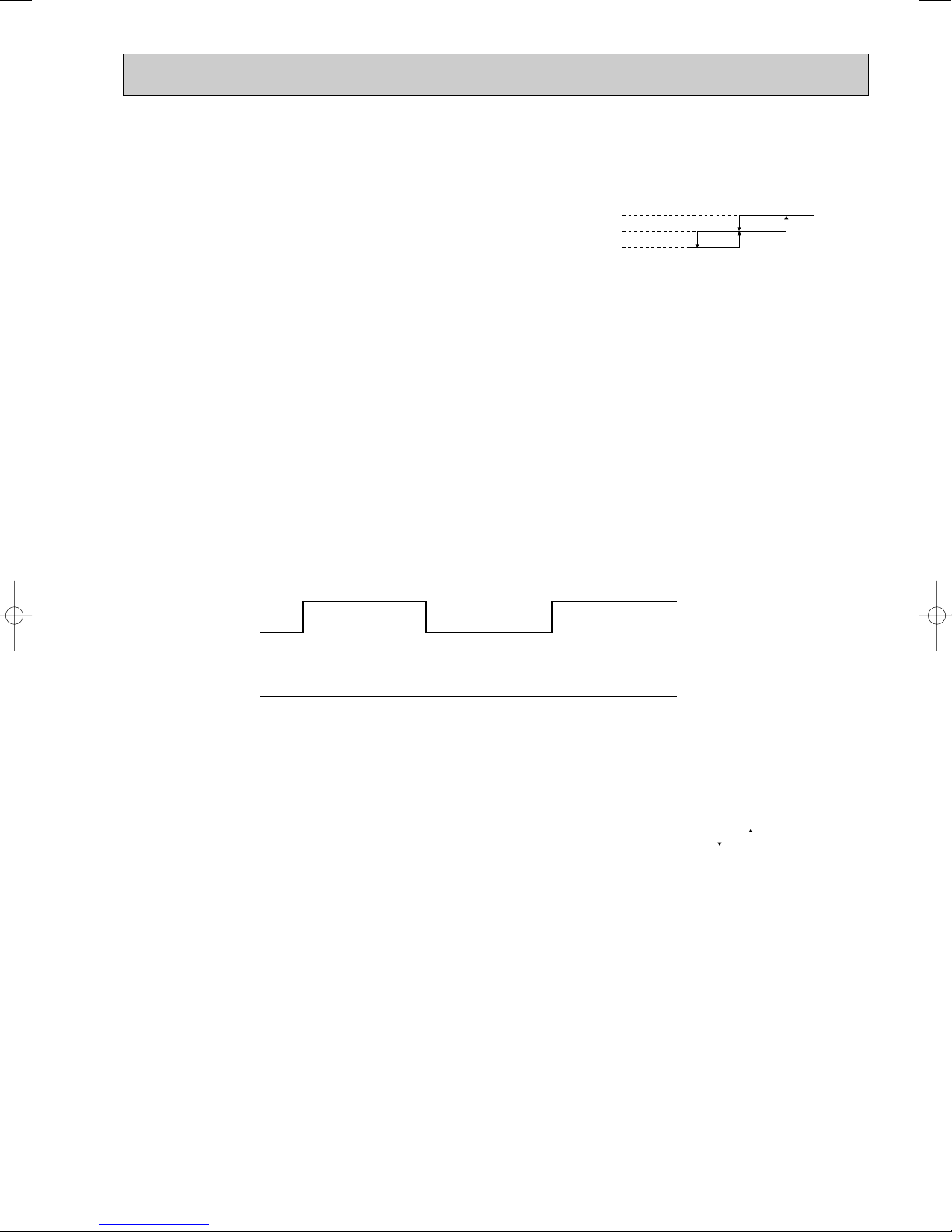
Operation chart
Example
ON
ON
Compressor
OFF
Outdoor fan
ON
Indoor fan
( continuously at set speed)
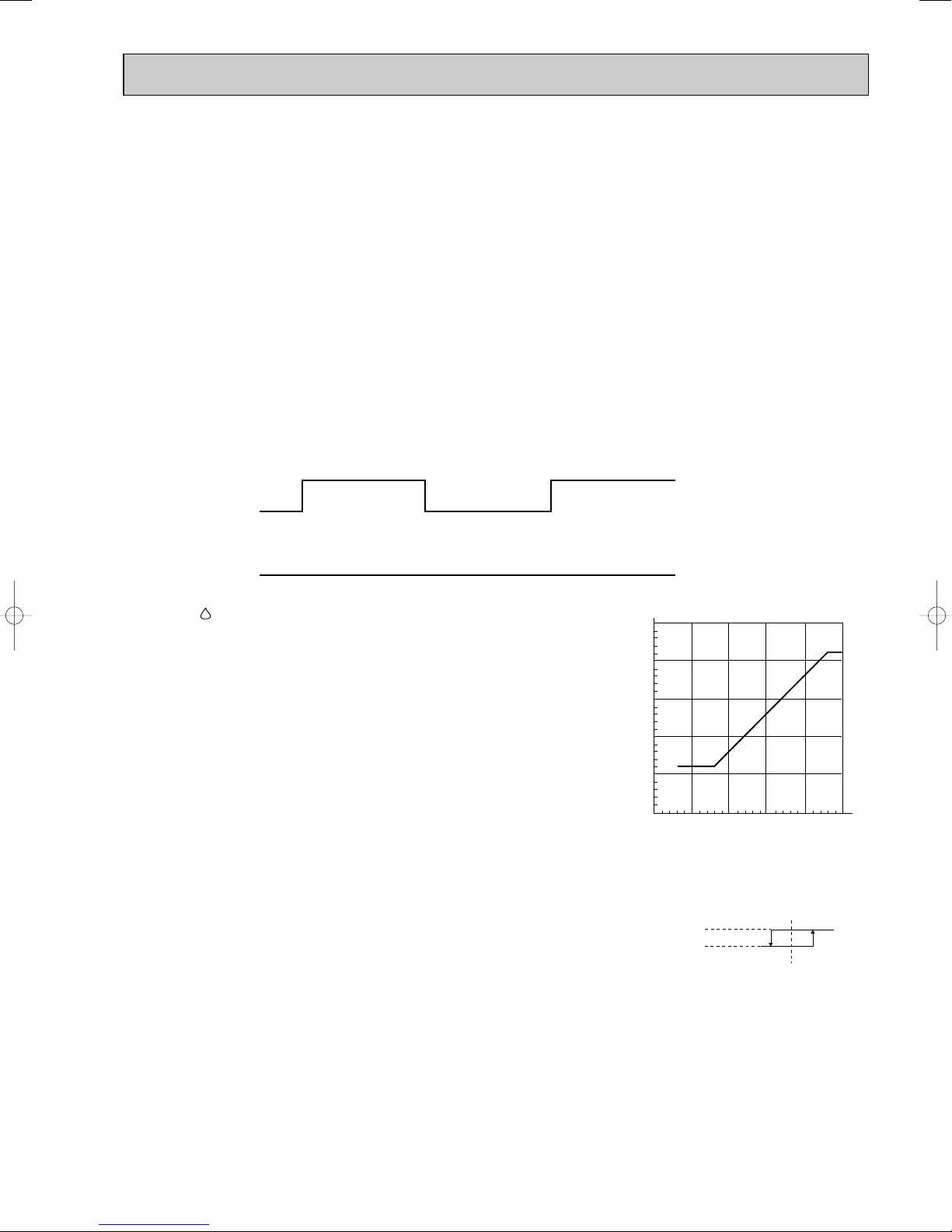
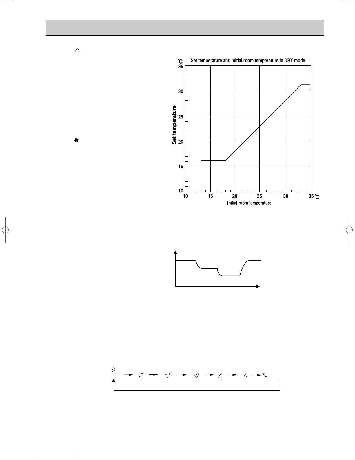
1-2. DRY ( ) OPERATION
(1) Press OPERATE/STOP(ON/OFF) button.
OPERATION INDICATOR lamp of the indoor unit turns on with a beep tone.
(2) Select DRY mode with the OPERATION SELECT button.
(3) The microprocessor reads the room temperature and determines the set tem-
perature. Set temperature is as shown on the right chart.
DRY operation will not function when the room temperature is 13°C or below.
(4) When DRY operation functions the fan speed is lower than COOL operation
except at (fan speed) Low.
The system for dry operation uses the same refrigerant circuit as the cooling
circuit.
The compressor and the indoor fan are controlled by the room temperature.
1. Thermostat control
Thermostat is ON or OFF by difference between room temperature and set temperature.
Room temperature minus set temperature : 0.3 : or more················································ON
Room temperature minus set temperature : less than -0.3 :············································OFF
2. Indoor fan speed control
Indoor fan operates at the set speed by FAN SPEED CONTROL button.
In Auto fan speed becomes Low.
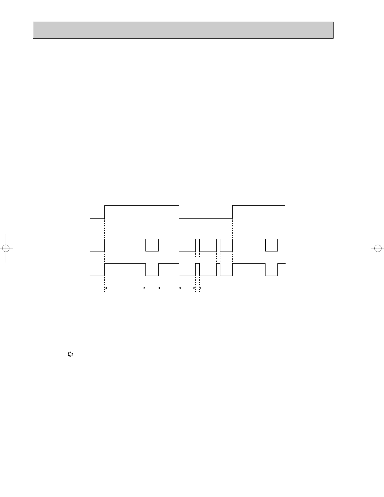
3. The operation of the compressor and indoor / outdoor fan
<MU-GA20/GA25/GA35VB, MUH-GA20/GA25/GA35VB, MUX-2A28/2A59/3A60/3A63/2A70/4A73VB>
Compressor operates by room temperature control and time control.
Indoor fan and outdoor fan operate in the same cycle as the compressor.
• When the room temperature is 23°C or over:
When the thermostat is ON, the compressor repeats 8 minutes ON and 3 minutes OFF.
When the thermostat is OFF, the compressor repeats 4 minutes OFF and 1 minute ON.
• When the room temperature is under 23°C.
When the thermostat is ON, the compressor repeats 2 minutes ON and 3 minutes OFF.
When the thermostat is OFF, the compressor repeats 4 minutes OFF and 1 minute ON.
OFF
Initial temperature difference Thermostat
7
Difference between room
temperature and set temperature during operation
Set temperature
-0.3 :
0.3 :

Operation time chart
Released
Cold Air Prevention
18: 22:
Fan speed
Set speed
Very Low or stop
Example
Thermostat
OFF
ON
ON
OFF
Indoor fan
Outdoor fan
Compressor
ON
ON
OFF
8 minutes
OFFOFF
OFF
ON
ON
3 minutes
OFF
OFF
4 minutes
ON
ON
1 minute
4. Coil frost prevention
The operation is as same as coil frost prevention during COOL operation.(Refer to 1-1.3.)
However when coil frost prevention works while the indoor fan is OFF, its speed becomes set speed.
1-3. FAN ( ) OPERATION <MU-GA20/GA25/GA35VB, MUX-2A28/2A59/3A60/3A63/2A70/4A73VB>
(1) Press OPERATE/STOP(ON/OFF) button. OPERATION INDICATOR lamp of the indoor unit turns on with a beep tone.
(2) Select FAN mode with OPERATION SELECT button.
(3) Select the desired fan speed. When AUTO, it becomes Low.
Only indoor fan operates.
Outdoor unit does not operate.
1-4. HEAT ( ) OPERATION <MUH-GA20/GA25/GA35VB>
(1) Press OPERATE/STOP(ON/OFF) button.
OPERATION INDICATOR lamp of the indoor unit turns on with a beep tone.
(2) Select HEAT mode with the OPERATION SELECT button.
(3) Press TEMPERATURE buttons (TOO WARM or TOO COOL button) to select the desired temperature.
The setting range is 16 ~ 31°C.
1. Thermostat control
Thermostat is ON or OFF by difference between room temperature and set temperature.
Initial temperature difference Thermostat
Room temperature minus set temperature : less than -0.3 :··············································ON
Room temperature minus set temperature : 0.3 : or more·················································OFF
Difference between room
temperature and set temperature during operation
Set temperature
-0.3 :
0.3 :
2. Indoor fan speed control
(1) Indoor fan operates at the set speed by FAN SPEED CONTROL button.
In Auto the fan speed is as follows.
Set temperature minus room temperature: 1.7 :or more······················································· High
Set temperature minus room temperature: Between 1 and 1.7 :··········································· Med.
Set temperature minus room temperature: less than 1
(2) Cold air prevention control
1 When the compressor is not operating,
(1) if the temperature of indoor coil thermistor RT12 is 0°C or less, the fan stops.
(2) if the temperature of indoor coil thermistor RT12 is more than 0°C, the fan operates at Very Low.
2 When the compressor is operating,
(1) if the temperature of RT12 is 22°C or more, the fan operates at set speed.
(2) if the temperature of RT12 is less than 22°C and
(1) if the temperature of room temperature thermistor RT11 is 15°C or less, the fan stops.
(2) if the temperature of room temperature thermistor RT11 is more than 15°C, the fan operates at Very Low.
NOTE : If the temperature of RT12 reads from 18°C to 22°C at the air conditioner stating and also after defrosting,
this control works.
Initial temperature difference
:
························································ Low
8
Fan speed
Difference between room
temperature and set temperature during operation
3 :
1.7 :
1:
(3) Warm air control
<Time condition>
<Indoor fan speed>
less than 2 minutes Low
2 minutes to 4 minutes Med.
more than 4 minutes High
Mode
COOL mode of
"I FEEL CONTROL"
DRY mode of
"I FEEL CONTROL"
HEAT mode of
"I FEEL CONTROL"
Initial room temperature
MUH type
25: or more
23:or more,
less than 25:
less than 23:
MU & MUX type
25: or more
more than13:,
less than 25:
When the following any conditions of 1 (a. ~ c.) and the condition of 2 are satisfied at the same time, warm air control
works.
1 a.) When outdoor unit starts operating in HEAT mode.
b.) When cold air prevention has been released.
c.) When defrosting has been finished
2 When the temperature of indoor coil thermistor RT12 is less than 37°C.
When warm air control works, the fan speed changes as follows to blow out warm air gradually.
Gradation of fan speed in initial
The upper limit of the fan speed in MANUAL is the set speed.
The upper limit of the fan speed in AUTO is the speed decided by indoor fan speed control.(Refer to 1-4.2.(1).)
When the temperature of RT12 has been 37°C or more, or when the set speed has been changed, this control is
released and the fan speed is the set speed.
NOTE: As for high pressure protection, defrosting and R.V. coil control, refer to service manual for outdoor unit.
1-5. “I FEEL CONTROL” ( ) OPERATION
(1) Press OPERATE/STOP(ON/OFF) button.
OPERATION INDICATOR lamp of the indoor unit turns on
with a beep tone.
(2) Select “I FEEL CONTROL”( ) mode with the OPERA-
TION SELECT button.
(3) The operation mode is determined by the initial room tem-
perature at start-up of the operation, as shown on the
right table.
• Once the mode is fixed, the mode does not change by room temperature afterwards.
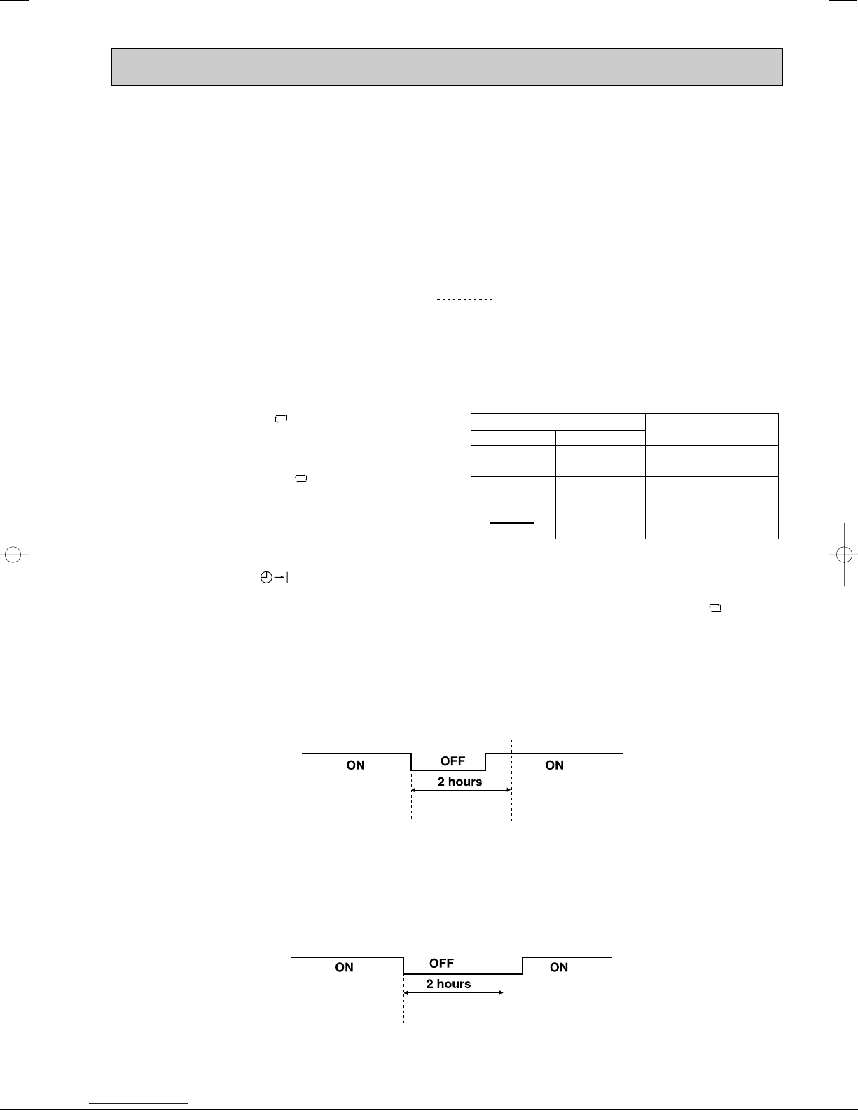
• Under the ON-TIMER ( ) operation, mode is determined as follows.
When the system is stopped on the remote controller and restarted within 2 hours in “I FEEL CONTROL” ( ) mode,
the system operates in previous mode automatically regardless of the room temperature.
Operation time chart
Example
Previous operation
COOL mode of
“I FEEL CONTROL”
or COOL mode
When the system is restarted after 2 hours and more, the operation mode is determined by the room temperature at
start-up of the operation.
Operation time chart
Example
Previous operation
COOL mode of
“I FEEL CONTROL”
or COOL mode
Restart
COOL mode of
“I FEEL CONTROL”
Restart
COOL or DRY or
HEAT mode of “I FEEL
CONTROL” that determined by room temperature at start-up of
the operation.
9
Mode
COOL mode of
"I FEEL CONTROL"
DRY mode of
"I FEEL CONTROL"
HEAT mode of
"I FEEL CONTROL"
Initial room temperature
Initial set temperature
26:
26: or more
25: or more,
less than 26:
23: or more,
less than25:
24:
Initial room temperature
minus 2:
Initial room temperature
minus 2:
❈1
more than 13:,
less than 25:
26: or more
25: or more,
less than 26:
less than 23:
MU & MUX type
MUH type
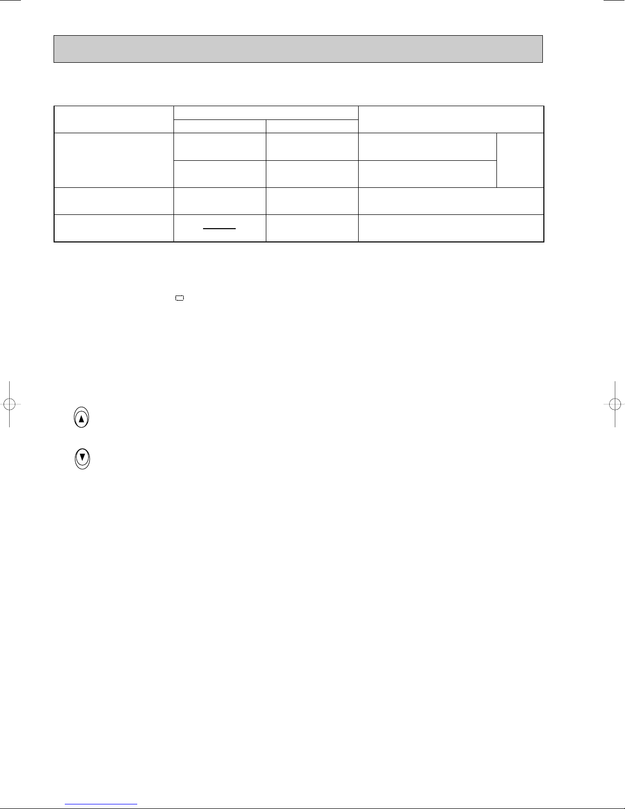
(4) The initial set temperature is decided by the initial room temperature.
TOO
COOL
TOO
WARM
❈1 When the system is restarted with the remote controller, the system operates with the previous set temperature regard-
less of the room temperature at restart.
(5) TEMPERATURES buttons
In “I FEEL CONTROL” ( ) mode, set temperature is decided by the microprocessor based on the room temperature.
In addition, set temperature can be controlled by TOO WARM or TOO COOL buttons when you feel too cool or too
warm. Each time the TOO WARM or TOO COOL button is pressed, the indoor unit receives the signal and emits a beep
tone.
• Fuzzy control
When the TOO COOL or TOO WARM button is pressed, the microprocessor changes the set temperature, considering
the room temperature, the frequency of pressing TOO COOL or TOO WARM button and the user’s preference to heat or
cool. So this is called “Fuzzy control”, and works only in “I FEEL CONTROL” mode.
In DRY mode of “I FEEL CONTROL”, the set temperature doesn’t change.
…
To raise the set temperature 1~2 degrees(°C)
…
To lower the set temperature 1~2 degrees(°C)
1-5-1. COOL mode of “I FEEL CONTROL”
1. Thermostat control
Thermostat control is as same as COOL OPERATION.(1-1.1.)
2. Indoor fan speed control
Indoor fan speed control is as same as COOL OPERATION.(1-1.2.)
3. Coil frost prevention
Coil frost prevention is as same as COOL OPERATION.(1-1.3.)
1-5-2. DRY mode of “I FEEL CONTROL”
1. Thermostat control
Thermostat control is as same as DRY OPERATION.(1-2.1.)
2. Indoor fan speed control
Indoor fan speed control is as same as DRY OPERATION.(1-2.2.)
3. The operation of the compressor and indoor/outdoor fan
The operation of the compressor and indoor/outdoor fan is as same as DRY OPERATION.(1-2.3.)
4. Coil frost prevention
Coil frost prevention is as same as DRY OPERATION.(1-2.4.)
1-5-3. HEAT mode of “I FEEL CONTROL” <MUH-GA20/GA25/GA35VB>
1. Thermostat control
Thermostat control is as same as HEAT OPERATION.(1-4.1.)
2. Indoor fan speed control
Indoor fan speed control is as same as HEAT OPERATION.(1-4.2.)
NOTE: As for high pressure protection, defrosting and R.V. coil control, refer to service manual for outdoor unit.
10
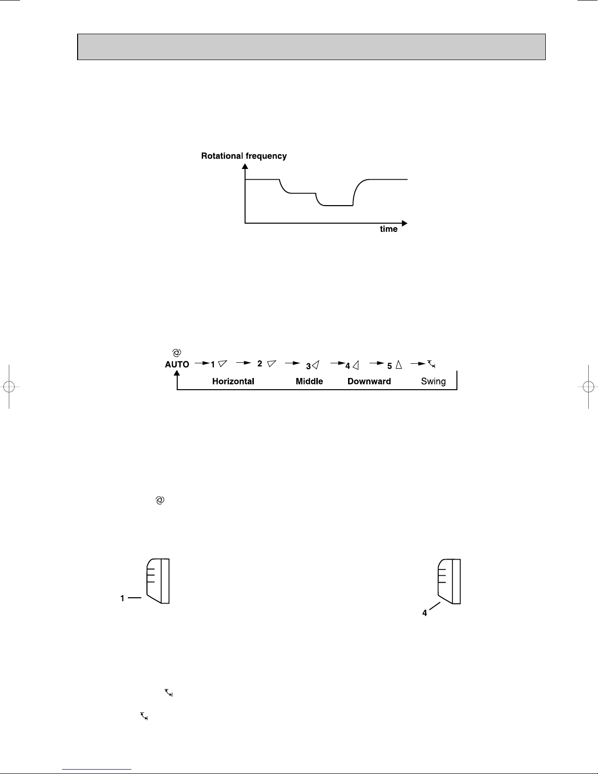
1-6. INDOOR FAN MOTOR CONTROL
(1) Rotational frequency feedback control
The indoor fan motor is equipped with a rotational frequency sensor, and outputs signal to the microprocessor to
feedback the rotational frequency. Comparing the current rotational frequency with the target rotational
frequency (High,Med.,Low), the microprocessor controls SR141 and adjusts fan motor electric current to make the
current rotational frequency close to the target rotational frequency. With this control, when the fan speed is switched,
the rotational frequency changes smoothly.
High High
Med.
Low
(2) Fan motor lock-up protection
When the rotational frequency feedback signal is not output for 12 seconds, (or when the microprocessor cannot detect
the signal for 12 seconds) the fan motor is regarded locked-up. Then the electric current to the fan motor is shut off. 3 minutes later, the electric current is applied to the fan motor again. During the fan motor lock-up, the OPERATION INDICATOR lamp flashes on and off to show the fan motor abnormality.
1-7. AUTO VANE OPERATION
(1) Vane motor drive
These models are equipped with a stepping motor for the horizontal vane. The rotating direction, speed, and angle of
the motor are controlled by pulse signals (approx. 12V) transmitted from indoor microprocessor.
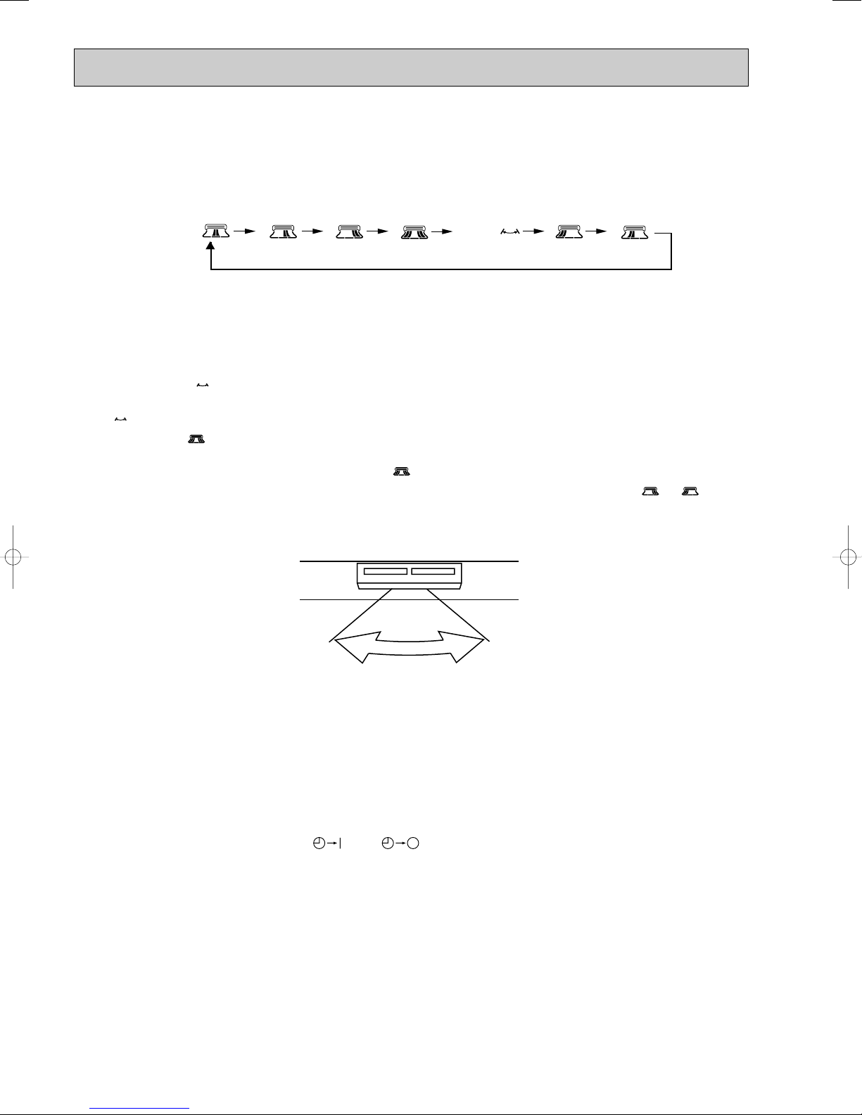
(2) The horizontal vane angle and mode change as follows by pressing the VANE CONTROL button.
(3) Positioning
The vane presses the vane stopper once to confirm the standard position and then set to the desired angle.
Confirming of standard position is performed in case of follows.
(a) When the OPERATE/STOP(ON/OFF) button is pressed.
(b) When the vane control is changed from AUTO to MANUAL.
(c) When the SWING is finished.
(d) When the test run starts.
(e) When the power supply turns ON.
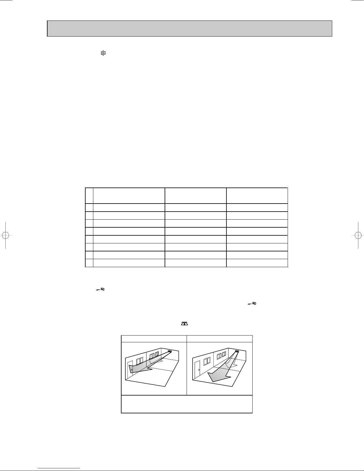
(4) VANE AUTO ( ) mode
The microprocessor automatically determines the vane angle to make the optimum room temperature distribution.
COOL and DRY operation
Vane angle is fixed to Angle 1.
(5) Dew prevention
During COOL or DRY operation at Vane Angle 4 or 5 when the cumulative operation time of compressor exceeds 1
hour, the vane angle automatically changes to Angle 1 for dew prevention.
(6) SWING MODE ( )
By selecting SWING mode with the VANE CONTROLbutton, the horizontal vane swings vertically. The remote controller
displays “”.
FAN operation
<MU-GA20/GA25/GA35VB, MUX-A28/2A59/3A60/3A63/2A70/4A73VB>
HEAT operation
<MUH-GA20/GA25/GA35VB>
Vane angle is fixed to Angle 4.
11
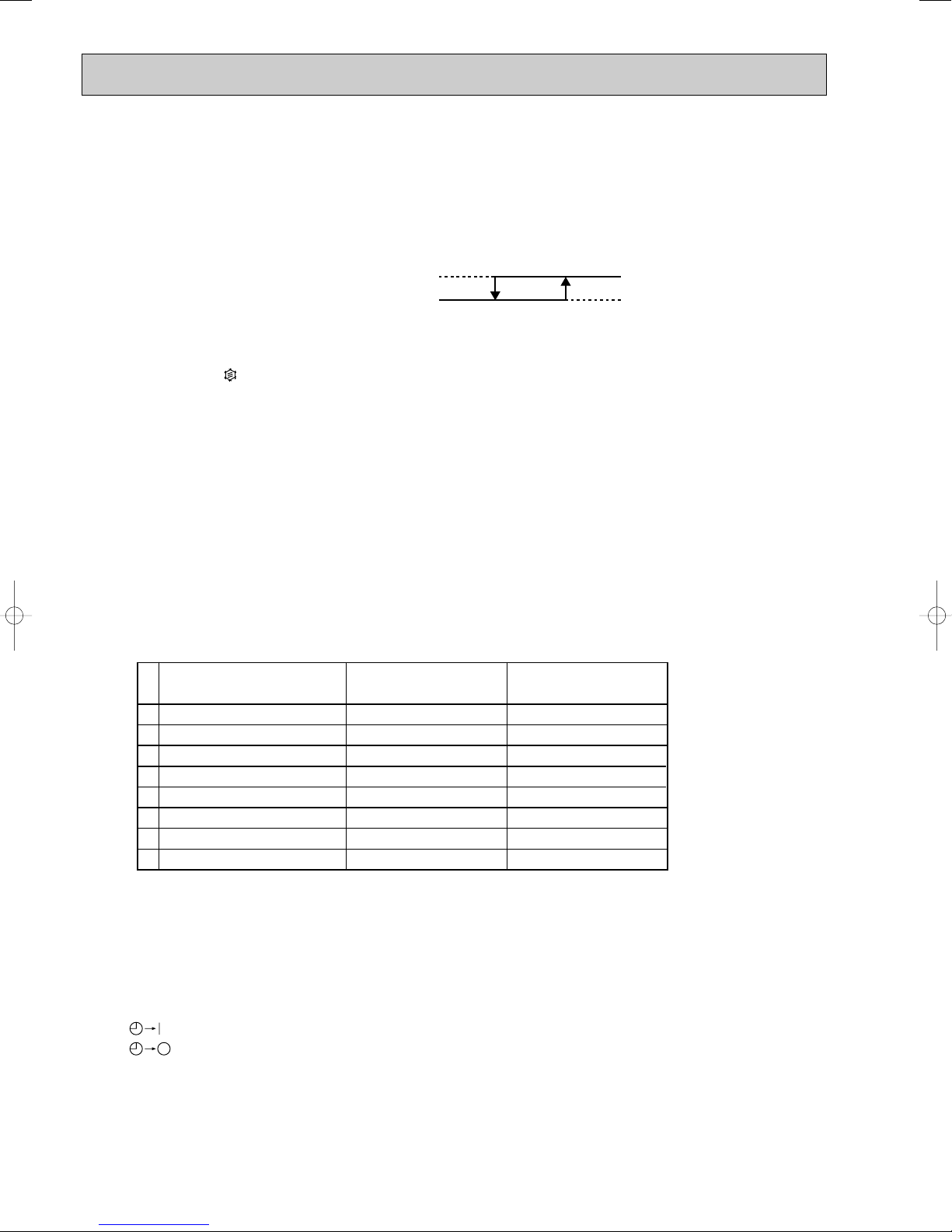
(7) Cold air prevention in HEAT operation
Set position
Angle 1
Released
Cold air prevention
24:
28:
When any of the following conditions occurs in HEAT operation, the horizontal vane angle changes to Angle 1 automatically to prevent cold air blowing on users.
① Compressor is not operating.
➁ Defrosting is performed.
➂ Indoor coil thermistor RT12 reads 24: or below.
➃ Indoor coil thermistor RT12 temperature is raising from 24°C or below, but it does not exceed 28:.
Indoor coil thermistor
RT12 temperature
NOTE : If the temperature of RT12 reads from 24°C to 28°C at the air conditioner stating , this control works.
(8) ECONO COOL ( ) operation (ECONOmical operation)
When the ECONO COOL button is pressed in COOL mode, set temperature is automatically set 2°C higher.
Also the horizontal vane swings in various cycle according to the temperature of indoor heat exchanger(RT12).
SWING operation makes you feel cooler than set temperature. So, even though the set temperature is higher, the air
conditioner can keep comfort. As a result, energy can be saved.
ECONO COOL operation is cancelled when the ECONO COOL button is pressed once again or VANE CONTROL button is pressed or operation mode is changed.
NOTE : ECONO COOL operation does not work in COOL mode of “I FEEL CONTROL”.
<SWING operation>
In swing operation of ECONO COOL operation mode, the initial air flow direction is adjusted to “Horizontal”.
According to the temperature of indoor coil thermistor RT12 at starting of this operation, next downward blow time is
decided. Then when the downward blow has been finished, next upward blow time is decided.
For initial 10 min. the swing operation is performed in table G~H for quick cooling.
Also, after 10 min. when the difference of set temperature and room temperature is more than 2 degrees, the swing
operation is performed in table D~H for more cooling.
The air conditioner repeats the swing operation in various cycle as follows.
<MUH-GA20/GA25/GA35VB>
Horizontal vane
Temperature of indoor
coil thermistor RT12
A
B
C
D
E
F
G
H
15°C or less
15°C to 17°C
17°C to 18°C
18°C to 20°C
20°C to 21°C
21°C to 22°C
22°C to 24°C
more than 24°C
Downward blow time
(sec.)
2
5
8
11
14
17
20
23
Horizontal blow time
(sec.)
23
20
17
14
11
8
5
2
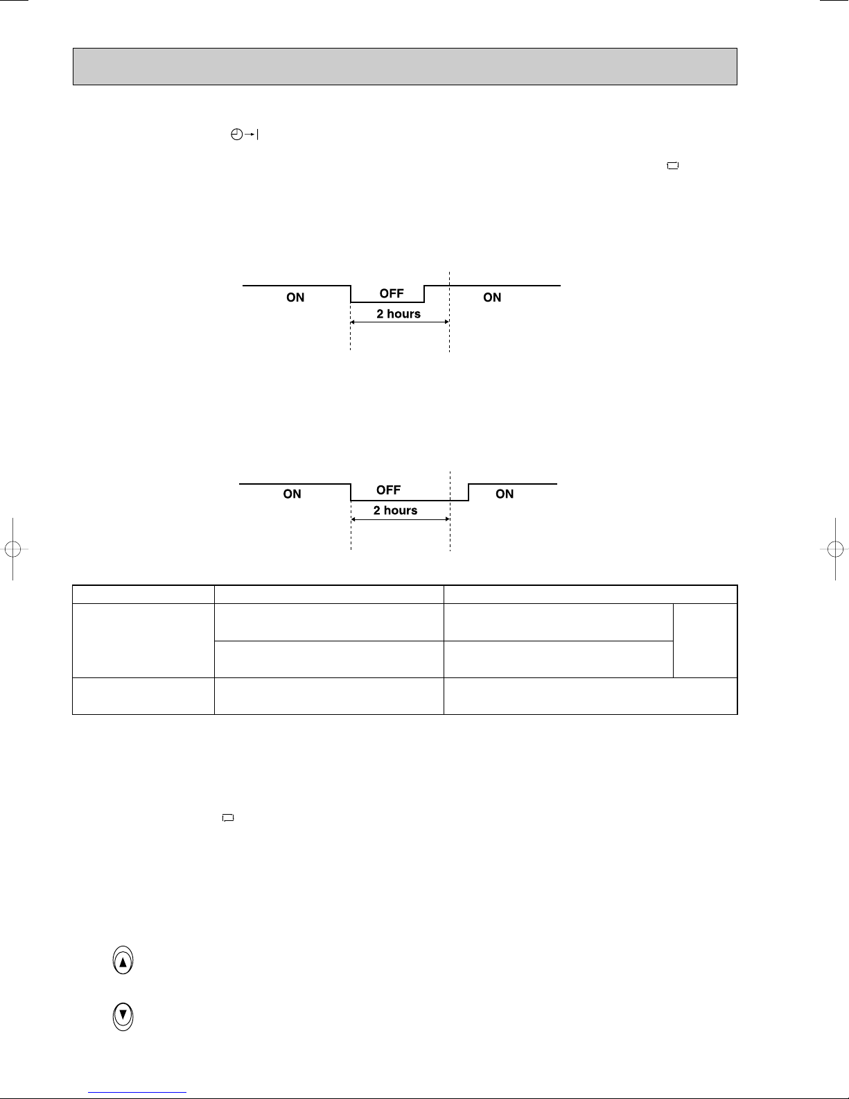
1-8. TIMER OPERATION
1. How to set the timer
(1) Press OPERATE/STOP(ON/OFF) button to start the air conditioner.
(2) Check that the current time is set correctly.
NOTE : Timer operation will not work without setting the current time. Initially “AM0:00” blinks at the current time display
of TIME MONITOR, so set the current time correctly with CLOCK SET button.
(3) Press ON or OFF TIMER buttons to select the operation.
“” button... AUTO START operation (ON timer)
“” button... AUTO STOP operation (OFF timer)
12
Lighted
Not lighted
PM
AM
PM
PM
(4) Press HR. and MIN. button to set the timer. Time setting is 10-minute units.
HR. and MIN. button will work when “” or “” mark is flashing.
These marks disappear in 1 minute.
After setting ON timer, check that OPERATION INDICATOR lamp of the indoor unit lights.
NOTE1 : Be sure to place the remote controller at the position where its signal can reach the air conditioner even during
TIMER operation, or the set time may deviate within the range of about 10 minutes.
NOTE2 : Reset the timer in the following cases, or the set time may deviate and other malfunctions may occur.
• Apower failure occurs.
• The circuit breaker functions.
2. Cancel
TIMER setting can be cancelled with ON or OFF TIMER buttons. (“” or “”)
To cancel ON timer, press “” button.
To cancel OFF timer, press “” button.
TIMER is cancelled and the display of set time disappears.
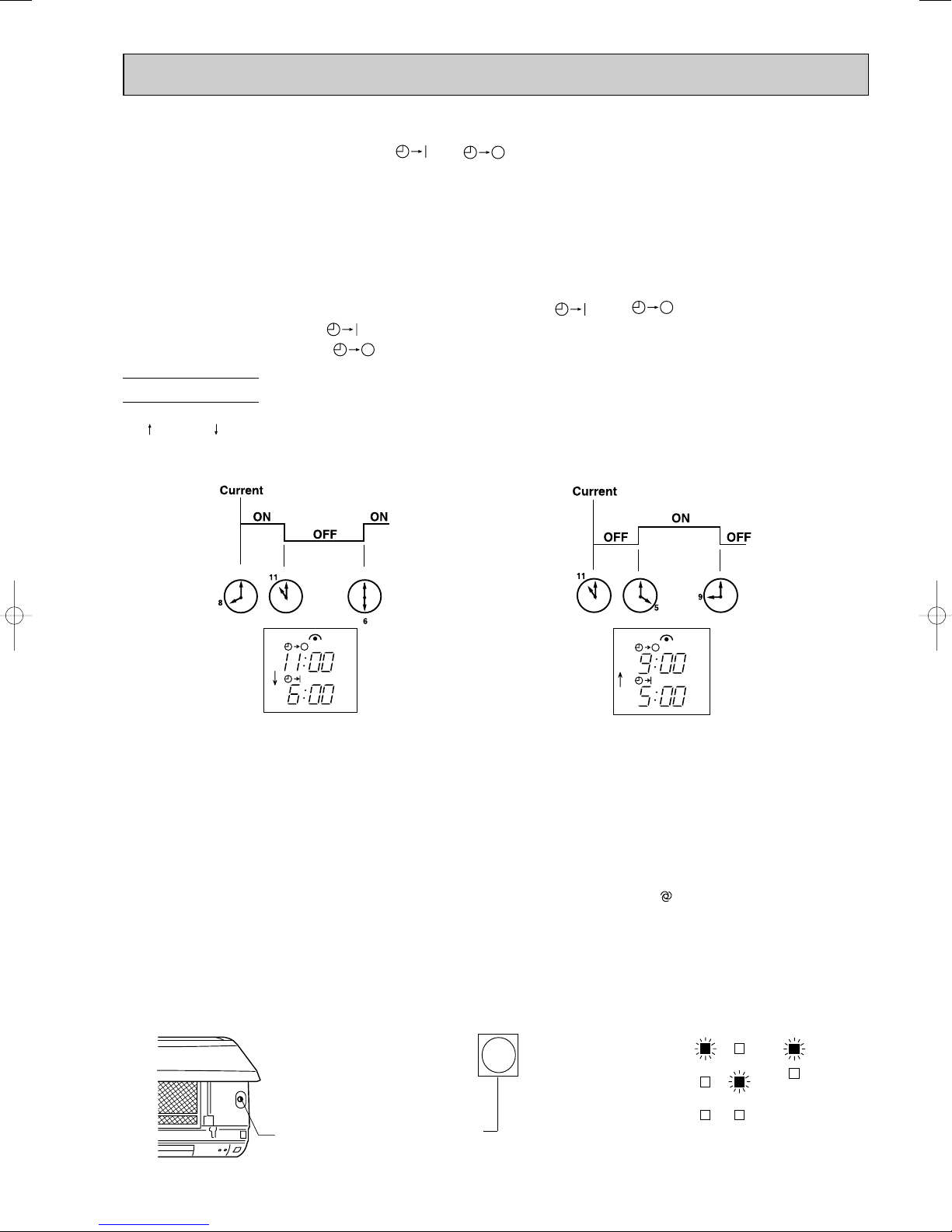
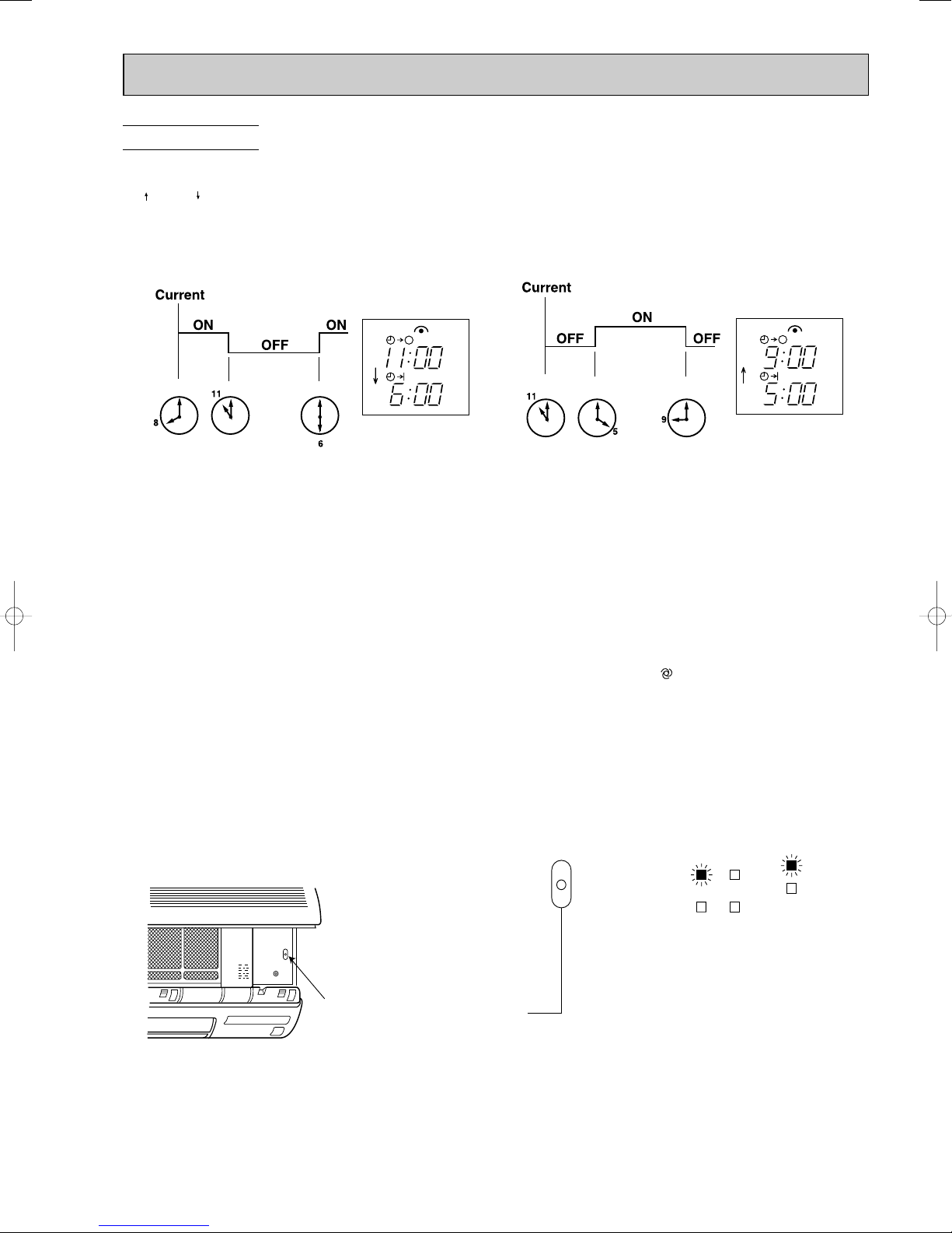
PROGRAM TIMER
• OFF timer and ON timer can be used in combination.
• “” and “ ” display shows the order of OFF timer and ON timer operation.
(Example 1) The current time is 8:00 PM.
The unit turns off at 11:00 PM, and on at 6:00 AM.
(Example 2) The current time is 11:00 AM.
The unit turns on at 5:00 PM, and off at 9:00 PM.
NOTE : TIMER setting will be cancelled by power failure or breaker functioning.
1-9. EMERGENCY / TEST OPERATION
In case of test run operation or emergency operation, use EMERGENCY OPERATION switch on the front of the
indoor unit. Emergency operation is available when the remote controller is missing, has failed or the batteries of remote
controller run down. The unit will start and OPERATION INDICATOR lamp will light.
The first 30 minutes of operation is the test run operation. This operation is for servicing. The indoor fan speed runs at
High speed and the system is in continuous operation. (The thermostat is ON.)
After 30 minutes of test run operation, the system shifts to EMERGENCY COOL [/ HEAT<MUH-GA20/GA25/GA35VB>]
MODE with a set temperature of 24°C. The fan speed shifts to Med. speed.
The coil frost prevention works even in emergency operation [, and defrosting<MUH-GA20/GA25/GA35VB> too].
In the test run or emergency operation, the horizontal vane operates in VANE AUTO ( ) mode.
Emergency operation continues until EMERGENCY OPERATION switch is pressed once again
(MU-GA20/GA25/GA35VB, MUX-2A28/2A59/3A60/3A63/2A70/4A73VB)/once or twice (MUH-GA20/GA25/GA35VB) or the
unit receives any signal from the remote controller.
In case of latter, normal operation will start.
NOTE : Do not press EMERGENCY OPERATION switch during normal operation.
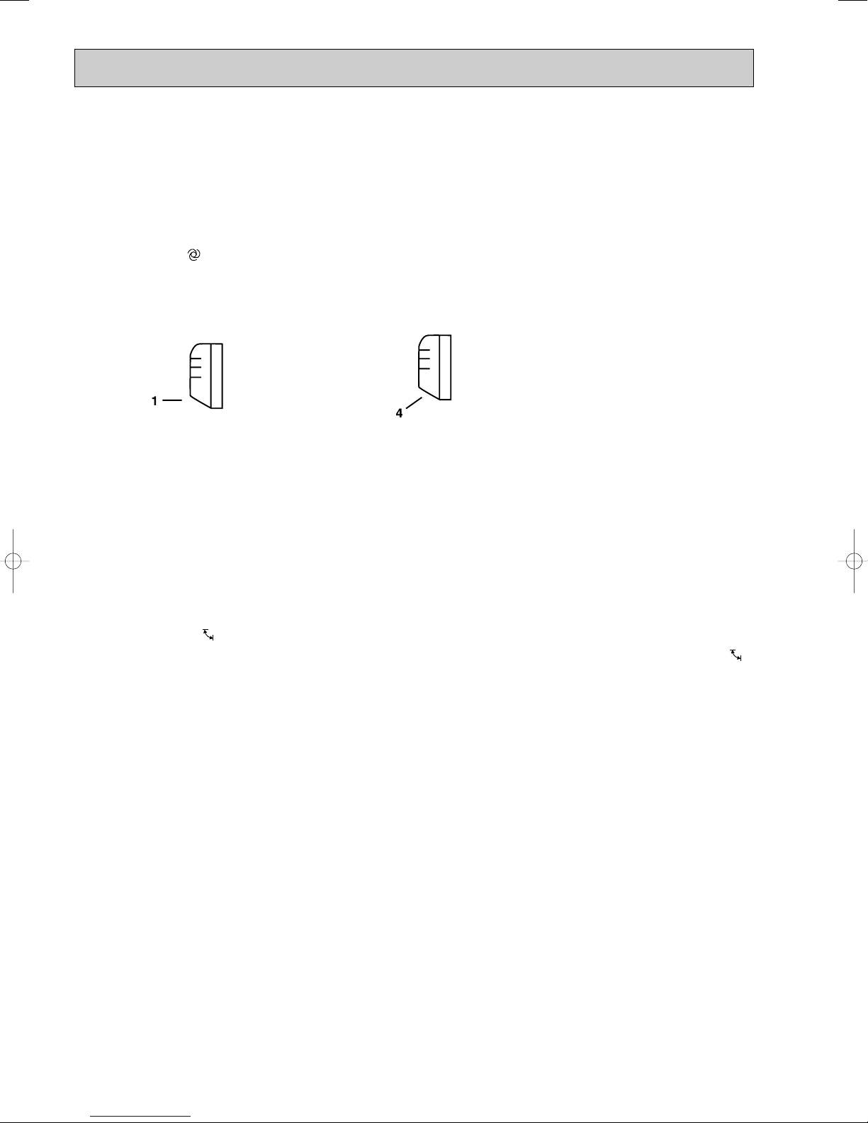
• The following indication does not depend on the
shape of lamp.
Press once <Cool>
OPERATION INDICATOR lamp
EMERGENCY OPERATION switch
Press again <Heat>
Press once again <Stop>
w Heat is available only in MUH-GA20/GA25/GA35VB.
13
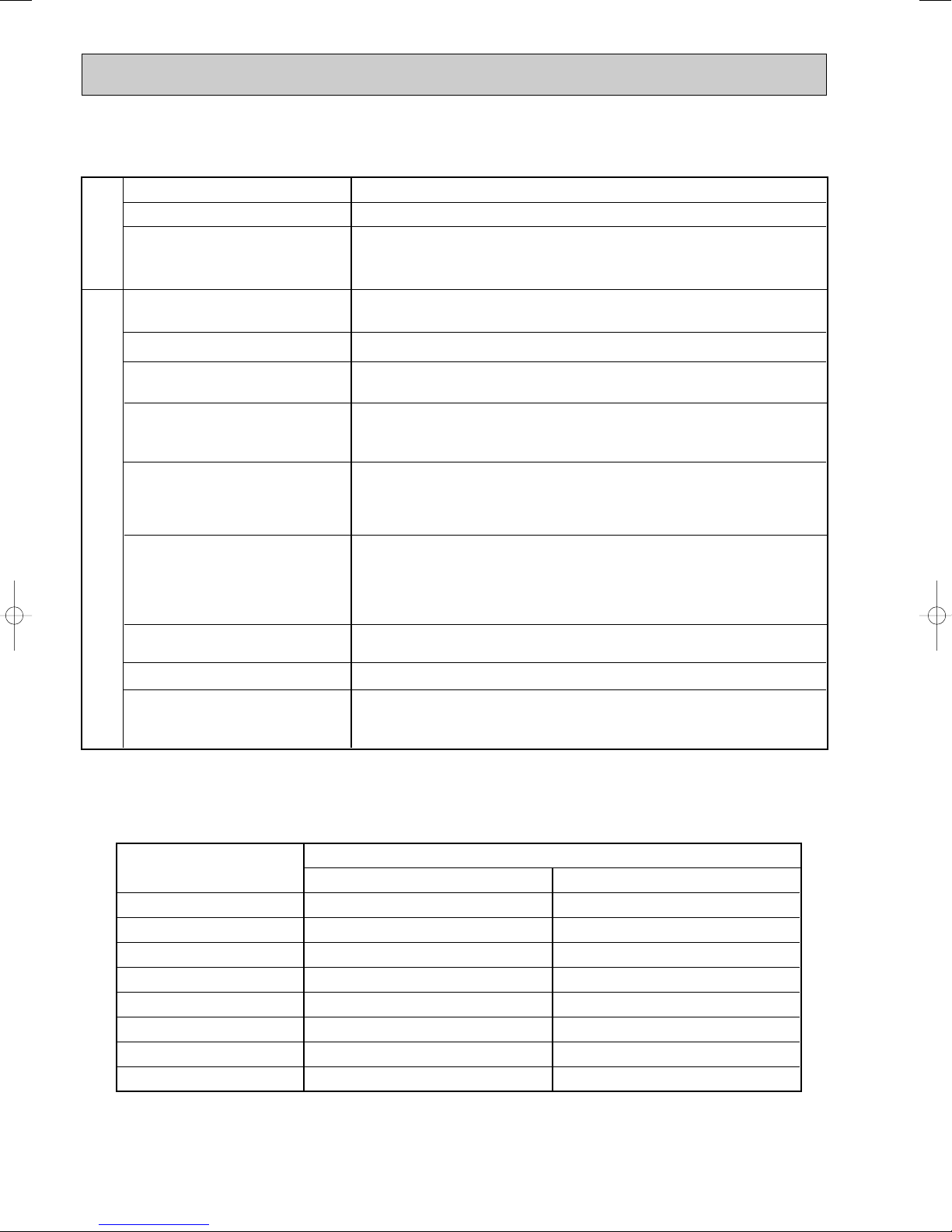
1-10. OUTDOOR UNIT ACTUATOR CONTROL
ACTUATOR
ON
OFF
ON
OFF
ON
OFF
ON (OPEN)
OFF (CLOSE)
ON (OPEN)
OFF (CLOSE)
ON (OPEN)
OFF (CLOSE)
ON (OPEN)
OFF (CLOSE)
ON (CLOSE)
OFF (OPEN)
ON (CLOSE)
OFF (OPEN)
SOLENOID
VALVE
MUX-4A73VB
INDOOR UNIT
MC1
MC2
MF61
21R1
21R2
21R3
21R4
21RA
(BALANCE)
21RB
(BALANCE)
COMPRESSOR
OUTDOOR
FAN MOTOR
A
ON
ON
OFF
OFF
–
–
–
–
OFF
ON
OFF
–
–
–
–
–
–
ON
ON
OFF
OFF
–
–
–
–
B
ON
OFF
ON
OFF
–
–
–
–
ANY UNIT ON
OFF
–
–
ON
OFF
–
–
–
–
ON
OFF
ON
OFF
–
–
–
–
C
–
–
–
–
ON
ON
OFF
OFF
OFF
–
–
–
–
ON
OFF
–
–
–
–
–
–
ON
ON
OFF
OFF
D
–
–
–
–
ON
OFF
ON
OFF
OFF
–
–
–
–
–
–
ON
OFF
–
–
–
–
ON
OFF
ON
OFF
ACTUATOR
ON
OFF
ON
OFF
ON
OFF
ON (OPEN)
OFF (CLOSE)
ON (OPEN)
OFF (CLOSE)
ON (CLOSE)
OFF (OPEN)
SOLENOID
VALVE
INDOOR UNIT
MC1
MC2
MF61
21R3
21R4
21RB
COMPRESSOR
OUTDOOR
FAN MOTOR
A
ON
OFF
–
–
–
–
OFF
–
–
–
–
–
–
–
–
B
–
–
ON
ON
OFF
OFF
ANY UNIT ON
OFF
ON
OFF
–
–
ON
ON
OFF
OFF
C
–
–
ON
OFF
ON
OFF
OFF
–
–
ON
OFF
ON
OFF
ON
OFF
ACTUATOR
ON
OFF
ON
OFF
ON (CLOSE)
OFF (OPEN)
ON (OPEN)
OFF (CLOSE)
ON (OPEN)
OFF (CLOSE)
SOLENOID
VALVE
MUX-2A28VB
INDOOR UNIT
MC
MF
21R
(BALANCE)
21R1
21R2
COMPRESSOR
OUTDOOR
FAN MOTOR
A
ON
ON
OFF
OFF
ANY UNIT ON
OFF
ON
ON
OFF
OFF
ON
OFF
–
–
B
ON
OFF
ON
OFF
OFF
ON
OFF
ON
OFF
–
–
ON
OFF
ACTUATOR
ON
OFF
ON
OFF
ON
OFF
MUX-2A59VB
MUX-2A70VB
INDOOR UNIT
MC1
MC2
MF61
COMPRESSOR
OUTDOOR
FAN MOTOR
A
ON
OFF
–
–
ANY UNIT ON
OFF
B
–
–
ON
OFF
OFF
MUX-3A60VB MUX-3A63VB
“–” means that the indoor unit is not related to the control of actuator.
14
2
ON/OFF
FAN
TOO
WARM
TOO
COOL
VANE
MODE
ECONO COOL
STOP
START
HR.
MIN.
WIDE VANE
LONG
I FEEL
COOL
DRY
PM
CLOCK
AM
RESET CLOCK
OPERATION SELECT button
FAN SPEED CONTROL button
OFF-TIMER button
HR. button
MIN. button
(TIME SET button)
ON-TIMER button
RESET button
ECONO COOL button
VANE button
(Horizontal vane button)
CLOCK SET button
LONG button
WIDE VANE button
(Vertical vane button)
ON/OFF
TOO
COOL
PM
AM
TOO
WARM
FAN
Signal transmitting section
Operation display section
OPERATE/ STOP
(ON/ OFF) button
TEMPERATURE buttons
Lighted
Not lighted
Approx.
2 : or more
Difference
between target
temperature
and room
temperature
Approx.
2 : or less
This shows that the
air conditioner is
operating to reach
the target temperature.
Please wait until the
target temperature is
obtained.
This shows that the
room temperature is
approaching the
target temperature.
Operation state
Indication
Operation Indicator
Operation Indicator lamp
The operation indicator at the right side of the indoor
unit indicates the operation state.
INDOOR UNIT DISPLAY SECTION
• The following indication applies regardless of
shape of the indicator.
MS MICROPROCESSOR CONTROL
MS-GA50VB MU-GA50VB
MS-GA60VB MU-GA60VB
MS-GA80VB MU-GA80VB
WIRELESS REMOTE CONTROLLER
Once the operation mode is set, the same operation mode can
be repeated by simply turning OPERATE/STOP (ON/OFF) button ON.
Indoor unit receives the signal with a beep tone.
When the system turns off, 3-minute time delay will operate to
protect system from overload and compressor will not restart
for 3 minutes.
2-1. “I FEEL CONTROL” ( ) OPERATION
(1) Press OPERATE/STOP (ON/OFF) button on the remote
controller. OPERATION INDICATOR lamp of the indoor
unit turns on with a beep tone.
(2) Select “I FEEL CONTROL” mode with OPERATION
SELECT button.
(3) The operation mode is determined by the room tempera-
ture at start-up of the operation.
Initial room temperature
25: or more
more than 13:,
less than 25:
15
Mode
COOL mode of
"I FEEL CONTROL"
DRY mode of
"I FEEL CONTROL"
• Once the mode is fixed, the mode does not change by room temperature afterwards.
Model
COOL mode of
"I FEEL CONTROL"
DRY mode of
"I FEEL CONTROL"
Initial room temperature Initial set temperature
26: or more
25: to 26:
more than 13:, less than 25:
24:
Initial room temperature
minus 2:
Initial room temperature
minus 2:
❈1
TOO
COOL
TOO
WARM
• Under the ON-TIMER ( ) operation, mode is determined as follows.
When the system is stopped on the remote controller, and restarted within 2 hours in “I FEEL CONTROL” ( ) mode,
the system operates in previous mode automatically regardless of the room temperature.
Operation timer chart
Example
Previous operation
COOL mode of
“I FEEL CONTROL”
Restart
COOL mode of
“I FEEL CONTROL”
or COOL mode
When the system is restarted after 2 hours and more, the operation mode is determined by the room temperature at
start-up of the operation.
Operation timer chart
Example
Previous operation
COOL mode of
“I FEEL CONTROL”
or COOL mode
Restart
COOL or DRY mode
of “I FEEL CONTROL”
that determined by
room temperature at
start-up of the operation.
(4) The initial set temperature is decided by the initial room temperature.
❈1 When the system is restarted with the remote controller, the system operates with the previous set temperature regard-
less of room temperature at restart.
The set temperature is calculated by the previous set temperature.
(5) TEMPERATURE buttons
In “I FEEL CONTROL” ( ) mode, set temperature is decided by the microprocessor based on the room temperature.
In addition, set temperature can be controlled by TOO WARM or TOO COOL buttons when you feel too cool or too warm.
Each time the TOO WARM or TOO COOL button is pressed, the indoor unit receives the signal and emits a beep tone.
• Fuzzy control
When the TOO COOL or TOO WARM button is pressed, the microprocessor changes the set temperature, considering
the room temperature, the frequency of pressing TOO COOL or TOO WARM button and the user’s preference to heat or
cool. So this is called “Fuzzy control”, and works only in “I FEEL CONTROL” mode.
In DRY mode of “I FEEL CONTROL”, the set temperature doesn’t change.
…
To raise the set temperature 1~2°C
…
To lower the set temperature 1~2°C
16
2-1-1. COOL mode of “I FEEL CONTROL”
Difference between room
temperature and set temperature
during operation
1°C 1.7°C
3°C
Outdoor fan speed
20: 22:
High
Ambient temperature
thermistor RT63 temperature
Low
1. Indoor fan speed control
Indoor fan operates at the set speed by FAN SPEED CONTROL button.
In AUTO the fan speed is as follows.
Initial temperature difference Fan Speed
Room temperature minus set temperature : 1.7 °Cor more
Room temperature minus set temperature : Between 1 and 1.7
Room temperature minus set temperature : less than 1
2. Coil frost prevention
① Temperature control
When the indoor coil thermistor RT12 reads 3°C or below(MS-GA50VB) /1°C or below(MS-GA60VB)/ RT12 or RT13
reads -1°C or below (MS-GA80VB), the coil frost prevention mode starts immediately.
However, the coil frost prevention doesn’t work for 5 minutes since the compressor has started.
The indoor fan operates at the set speed and the compressor stops for 5 minutes.
After that, if RT12 still reads below 3°C(MS-GA50VB)/ 1°C(MS-GA60VB)/ RT12 or RT13 still reads below-1°C
(MS-GA80VB) this mode prolonged until the RT12 reads over 3°C(MS-GA50VB)/ 1°C(MS-GA60VB) / RT12 or RT13 still
reads over-1°C(MS-GA80VB).
② Time control
When the three conditions as follows have been satisfied for 1 hour and 45 minutes, compressor stops for 3 minutes.
a. Compressor has been continuously operating.
b. Indoor fan speed is Low or Med.
c. Room temperature is below 26°C.
When compressor stops, the accumulated time is cancelled and when compressor restarts, time counting starts from the
beginning.
Time counting also stops temporarily when the indoor fan speed becomes High or the room temperature exceeds
26°C. However, when two of the above conditions (b.and c.) are satisfied again. Time accumulation is resumed.
Operation chart
Example
Compressor
OFF
ON
Outdoor fan
···································High
°C························Med.
°C····································Low
ON
OFF
(continuously at set speed)
Indoor fan
ON
3. Outdoor fan speed control <MU-GA80VB>
Outdoor fan speed is controlled according to the temperature of ambient temperature thermistor RT63.
Outdoor fan Low operation : When the outside temperature decreases to 20°C or less.
Until the outside temperature goes to 22°C.
Outdoor fan High operation : Until the outside temperature decreases to 20°C or less.
When the outside temperature goes to 22°C.
NOTE : When indoor fan speed is Low except FAN operation mode and the outside temperature is 30: or less, the
outdoor fan operates at Low.
Outdoor fan Low operation is cancelled according to the following conditions(1 or 2):
1 When the operation is not changed and the outside temperature goes to 33: or more.
2 When the operation is changed. (Change to FAN operation mode / Change of the indoor fan speed)
4. Discharge temperature protection <MU-GA80VB>
The compressor is controlled by the temperature of discharge temperature thermistor RT62 for excess rise protection of
compressor discharge pressure.
• Compressor
When the temperature of discharge temperature thermistor RT62 goes to 120: or more, the compressor is turned OFF.
After 3 minutes since the compressor has been turned OFF, if the temperature of discharge temperature thermistor RT62
becomes 100: or less, the compressor is turned ON.
17
2-1-2. DRY mode of “I FEEL CONTROL”
The system for dry operation uses the same refrigerant circuit as the cooling circuit.
The compressor and the indoor fan are controlled by the room temperature.
By such controls, indoor flow amounts will be reduced in order to lower humidity without much room temperature decrease.
1. Indoor fan speed control
Indoor fan operates at the set speed by FAN SPEED CONTROL button.
However, in AUTO fan operation, fan speed becomes Low.
2. The operation of the compressor and indoor/ outdoor fan
Compressor operates by room temperature control and time control.
Set temperature is controlled to fall 2°C from initial room temperature.
Indoor fan and outdoor fan operate in the same cycle as the compressor.
•When the room temperature is 23°C or over:
When the thermostat is ON, the compressor repeats 8 minutes ON and 3 minutes OFF.
When the thermostat is OFF, the compressor repeats 4 minutes OFF and 1 minute ON.
•When the room temperature is under 23°C.
When the thermostat is ON, the compressor repeats 2 minutes ON and 3 minutes OFF.
When the thermostat is OFF, the compressor repeats 4 minutes OFF and 1 minute ON.
Operation time chart
Example
ON
ON
Thermostat
Indoor fan
Outdoor fan
OFF
OFF
OFF
ON
ON
ON
OFF
ON
OFF
OFF
ON
OFF
ON
OFF
Compressor
8 minutes
3 minutes
4 minutes
1 minute
3. Coil frost prevention
• The operation is as same as coil frost prevention during COOL mode of “I FEEL CONTROL”.
• Indoor fan operates at the set speed and the compressor stops for 5 minutes, because protection(Coil frost
prevention) has the priority.
However, when coil frost prevention works while the compressor is not operating, its speed becomes Low.
4. Outdoor fan speed control <MU-GA80VB>
Outdoor fan speed control is as same as one of COOL mode of “I FEEL CONTROL”.
2-2. COOL ( ) OPERATION
(1) Press OPERATE/STOP (ON/OFF) button.
OPERATION INDICATOR lamp of the indoor unit turns on with a beep tone.
(2) Select COOL mode with OPERATION SELECT button.
(3) Press TEMPERATURE buttons.
(TOO WARM or TOO COOL button) to select the desired temperature.
The setting range is 16 ~ 31°C.
✻ Indoor fan continues to operate regardless of thermostat’s OFF-ON at set speed.
✻ Coil frost prevention is as same as COOL mode of “I FEEL CONTROL”.
18
AUTO
Horizontal
12
34 5
Middle Downward Swing
2-3. DRY ( ) OPERATION
(1) Press OPERATE/STOP (ON/OFF) button.
OPERATION INDICATOR lamp of the indoor
unit turns on with a beep tone.
(2) Select DRY mode with OPERATION SELECT
button.
(3) The microprocessor reads the room tempera-
ture and determines the set temperature. Set
temperature is as shown on the right chart.
Thermostat (SET TEMP.)does not work.
The other operations are same as DRY mode of
“I FEEL CONTROL”.
(4) DRY operation will not function when the room
temperature is 13°C or below.
2-4. FAN ( ) OPERATION
(1) Press OPERATE/STOP(ON/OFF) button.
OPERATION INDICATOR lamp of the indoor
unit turns ON with a beep tone.
(2) Select FAN mode with OPERATION
SELECT button.
(3) Select the desired fan speed. When AUTO, it
becomes Low.
Only indoor fan operates. Outdoor unit does not
operate.
2-5. INDOOR FAN MOTOR CONTROL
(1) Rotational frequency feedback control
The indoor fan motor is equipped with a rotational frequency sensor, and outputs signal to the microprocessor to
feedback the rotational frequency. Comparing the current rotational frequency with the target rotational frequency
(High, Med., Low), the microprocessor controls SR141 and adjusts fan motor electric current to make the current rotational frequency close to the target rotational frequency. With this control, when the fan speed is switched, the rotational
frequency changes smoothly.
Rotational frequency
High
High
Med.
Low
(2) Fan motor lock-up protection
When the rotational frequency feedback signal has not output for 12 seconds, (or when the microprocessor cannot
detect the signal for 12 seconds) the fan motor is regarded locked-up. Then the electric current to the fan motor is shut
off. 3 minutes later, the electric current is applied to the fan motor again. During the fan motor lock-up, the OPERATION
INDICATOR Indicator lamp flashes on and off to show the fan motor abnormality.
2-6. AUTO VANE OPERATION
1. Horizontal vane
(1) Vane motor drive
These models are equipped with a stepping motor for the horizontal vane. The rotating direction, speed, and angle of
the motor are controlled by pulse signals (approx. 12V) transmitted from indoor microprocessor.
(2) The horizontal vane angle and mode change as follows by pressing the VANE button.
time
19
(3) Positioning
The vane presses the vane stopper once to confirm the standard position and then moves to the set angle.
Confirming of standard position is performed in case of follows.
(a) When the power supply turns ON.
(b) When the operation starts or finishes (including timer operation).
(c) When the test run starts.
(d) When the vane control is changed AUTO to MANUAL(except SWING).
(e) When the SWING is finished (including ECONO COOL).
(4) VANE AUTO ( ) mode
The microprocessor automatically determines the horizontal vane angle and operation to make the optimum room temperature distribution.
COOL and DRY operation
Vane angle is fixed to Angle 1.
FAN operation
Vane angle is fixed to Angle 4.
(5) STOP (operation OFF) and ON-TIMER standby
When the following cases occur, the horizontal vane returns to the closed position.
(a) When OPERATE/STOP (ON/OFF) button is pressed (POWER OFF).
(b) When the operation is stopped by the emergency operation.
(c) When ON-TIMER is on standby.
(6) Dew prevention
During COOL or DRY operation at Vane Angle 4 or 5 when the compressor cumulative operation time of compressor
exceeds 1 hour, the vane angle automatically changes to Angle 1 for dew prevention.
(7) SWING MODE ( )
By selecting SWING mode with VANE button, the horizontal vane swings vertically. The remote controller displays “”.
SWING mode is cancelled when VANE button is pressed once again.
20
COOL / DRY FAN
Fan speed : Faster
Solid arrow : When LONG mode is used.
Dotted arrow : When LONG mode is not used.
(8) ECONO COOL ( ) operation (ECONOmical operation)
When ECONO COOL button is pressed in COOL mode, set temperature is automatically set 2°C higher.
Also the horizontal vane swings in various cycle according to the temperature of indoor heat exchanger(Tp
(w 1)).
SWING operation makes you feel cooler than set temperature. So, even though the set temperature is higher, the air
conditioner can keep comfort. As a result, energy can be saved.
ECONO COOL operation is cancelled when ECONO COOL button is pressed once again or VANE button is pressed or
LONG button is pressed or change to other operation mode.
NOTE : ECONO COOL operation does not work in COOL mode of “I FEEL CONTROL”.
<SWING operation>
w 1 Tp : • Value of RT12 (MS-GA50/GA60VB)
• Minimum value of indoor coil thermistor (main) RT12 and indoor coil thermistor (sub) RT13 (MS-GA80VB)
In swing operation of ECONO COOL operation mode, the initial air flow direction is adjusted to “Horizontal”.
According to the temperature of indoor coil thermistor Tp
(w 1) at starting of this operation, next downward blow time is
decided. Then when the downward blow has been finished, next horizontal blow time is decided.
For initial 10 minutes the swing operation is performed in table G~H for quick cooling.
Also, after 10 minutes when the difference of set temperature and room temperature is more than 2:, the swing operation is performed in table D~H for more cooling.
The air conditioner repeats the swing operation in various cycle as follows.
Temperature of Tp
A
B
C
D
E
F
G
H
15°C or less
15°C to 17°C
17°C to 18°C
18°C to 20°C
20°C to 21°C
21°C to 22°C
22°C to 24°C
more than 24°C
(w 1)
Downward blow time
(second)
2
5
8
11
14
17
20
23
Horizontal blow time
(second)
23
20
17
14
11
8
5
2
(9) LONG MODE ( )
By pressing LONG button indoor fan speed becomes faster than setting fan speed on the remote controller, and the horizontal vane moves to the position for LONG mode. The remote controller displays “”. LONG mode is cancelled
when LONG button is pressed once again or VANE button is pressed or ECONO COOLbutton is pressed in COOL
mode.
• In the following example, the vertical vane is set to (front.).
21
About 100-
Horizontal AIR FLOW blowing range
61
23
45SWING
2. Vertical vane
(1) Vane motor drive
These models are equipped with a stepping motor for the vertical vane. The rotating direction, speed, and angle of the
motor are controlled by pulse signals (approx. 12V) transmitted from microprocessor.
(2) The vertical vane angle and mode change as follows by pressing WIDE VANE button.
(3) Positioning
The vane is once pressed to the vane stopper to confirm the standard position and then set to the desired angle.
Confirming of standard position is performed in case of follows.
(a) When OPERATE/STOP(ON/OFF) button is pressed (POWER ON/OFF).
(b) When SWING is started or finished.
(c) When the power supply turns ON.
(4) SWING MODE ( )
By selecting SWING mode with WIDE VANE button, the vertical vane swings horizontally. The remote controller displays
“”. The vane moves right and left in the width of Angle 4 repeatedly.
(5) WIDE MODE ( )
By selecting WIDE mode with WIDE VANE button, indoor fan speed becomes faster than setting fan speed on the
remote controller (W). The remote controller displays “”.
W Indoor fan speed becomes faster than setting fan speed on the remote controller even when or is
selected.
2-7. TIMER OPERATION
1. How to set the timer
(1) Press OPERATE/STOP (ON/OFF) button to start the air conditioner.
(2) Check that the current time is set correctly.
NOTE : Timer operation will not work without setting the current time. Initially “AM0:00” blinks at the current time display of
TIME MONITOR, so set the current time correctly with CLOCK SET button.
(3) Press ON/OFF TIMER buttons to select the operation.
“ON-TIMER” button... AUTO START operation (ON timer)
“OFF-TIMER” button... AUTO STOP operation (OFF timer)
(4) Press HR. and MIN. button to set the timer. Time setting is 10-minute units.
HR. and MIN. button will work when “” or “” mark is flashing.
These marks disappear in 1 minute.
After setting the ON timer, check that OPERATION INDICATOR lamp of the indoor unit lights.
NOTE1 : Be sure to place the remote controller at the position where its signal can reach the air conditioner even during
TIMER operation, or the set time may deviate within the range of about 10 minutes.
NOTE2 : Reset the timer in the following cases, or the set time may deviate and other malfunctions may occur.
• Apower failure occurs.
•The circuit breaker functions.
2. Cancel
TIMER setting can be cancelled with ON/OFF TIMER buttons.
To cancel ON timer, press “ON-TIMER” button.
To cancel OFF timer, press “OFF-TIMER” button.
TIMER is cancelled and the display of set time disappears.
22
PROGRAM TIMER
PM
AM
PM
PM
• OFF timer and ON timer can be used in combination.
• “” and “” display shows the order of OFF timer and ON timer operation.
(Example 1) The current time is 8:00 PM.
The unit turns off at 11:00 PM, and on at 6:00 AM.
(Example 2) The current time is 11:00 AM.
The unit turns on at 5:00 PM, and off at 9:00 PM.
NOTE : TIMER setting will be cancelled by power failure or breaker functioning.
2-8. EMERGENCY / TEST OPERATION
In case of test run operation or emergency operation, use EMERGENCY OPERATION switch on the front of the indoor
unit. Emergency operation is available when the remote controller is missing, has failed or the batteries of remote controller run down. The unit will start and OPERATION INDICATOR lamp will light.
The first 30 minutes of operation is the test run operation. This operation is for servicing. The indoor fan speed runs at
High speed and the system is in continuous operation. (The thermostat is ON.)
After 30 minutes of test run operation, the system shifts to EMERGENCY COOL MODE with a set temperature of 24°C.
The fan speed shifts to Med. speed.
The coil frost prevention works even in emergency operation.
In the test run or emergency operation, the horizontal vane operates in VANE AUTO ( ) mode.
Emergency operation continues until EMERGENCY OPERATION switch is pressed again or the unit receives any
signal from the remote controller. In case of latter, normal operation will start.
NOTE : Do not press EMERGENCY OPERATION switch during normal operation.
• The following indication applies regardless of
shape of the indicator.
OPERATION INDICATOR lamp
Press once <Cool>
Press again <Stop>
EMERGENCY OPERATION switch
23
Lighted
Not Lighted
Rank
Ta (:)
more than Tb+10
Tb+5 to Tb+10
Tb+2 to Tb+5
Tb-2 to Tb+2
Tb-5 to Tb-2
Tb-10 to Tb-5
less than Tb-10
100 pulse or less
Cooling
5
2
1
0
-1
-2
-5
NOTE : Discharge temperature : Ta, Target discharge temperature : Tb
100 pulse or more
Cooling
20
10
2
0
-2
-5
-10
Opening immediately before having stopped last time
2-9. EXPANSION VALVE CONTROL (LEV CONTROL) <MU-GA80VB>
Controlled range
Basic specification
Minimum : 54 pulse, Maximum : 500 pulse
Drive speed
30 ~ 90 pulse / second
Opening set
The setting is always in opening direction.
(To close the LEV, it is closed to the pulse smaller than the one which is
set finally. Then the LEV is opened to the final setting pulse.)
Stop of indoor unit
Opening in stop : 150 pulse ➔ LEV opening is set to becomes 500 pulse
after 3 minutes passed.
Remote controller ON
LEV positioning (LEV is closed completely at once)
Power ON (Breaker ON)
LEV is positioned. However, afterwards, LEV is not positioned at the first
remote controller ON.
Approximate for 2 minutes since
compressor has started.
Opening is set by the initial opening.
(Initial opening is set according to each operation modes and
outer temperature conditions.)
From approximate 2 minutes to
approximate 13 minutes
(for 11 minutes) since compressor
has started.
Opening is set by standard opening.
(Standard opening is set according to each operation modes and
outer temperature conditions.)
After 13 minutes passed since
compressor has started.
LEV opening is corrected to be once every 2 minutes so that discharge
temperature becomes the target discharge temperature.
(When the discharge temperature is lower than target : LEV is corrected in
closed direction, when the discharge temperature is higher than target :
LEV is corrected in opening direction.)
At thermostat OFF
Opening in stop : 150 pulse ➔ LEV is set to the initial opening after about
3 minutes passed.
At thermostat ON
Same as the starting of compressor operation
At remote controller OFF
Opening in stop : 150 pulse ➔ LEV is set so that the opening is opened
completely at the speed of 4 pulse every 5 seconds in opening after about
3 minutes passed.
General operation
LEV (Expansion valve) is controlled by “Thermostat ON” commands given from the unit.
(1) LEV opening correction by discharge temperature
The LEV opening is corrected according to the temperature difference between target discharge temperature (Tb) and
actual discharge temperature (Ta).
1 The LEV correction is used properly for two kinds according to the LEV opening status at operation off.
24
2 When the temperature difference RT between indoor coil thermistor (main) RT12 and indoor coil thermistor (sub)
Ta (:)
more than Tb+10
Tb+5 to Tb+10
Tb+2 to Tb+5
Tb-2 to Tb+2
Tb-5 to Tb-2
Tb-10 to Tb-5
less than Tb-10
less than 2:
20
10
2
0
-2
-5
-10
NOTE : Discharge temperature : Ta, Target discharge temperature : Tb
3: or more
60
20
2
0
-2
-5
-10
RT
2: or more and less than 3:
60
20
2
0
-2
-5
-10
Tb (:)
COOL (Normal)
COOL ( RT is less than 2:, or RT is 2:or more and less than 3:.)
COOL ( RT is 3 :or more.)
NOTE : Target discharge temperature : Tb
80
70
65
Operation mode
NOTE : Opening increases and decreases to be in the target discharge temperature during operation.
Opening
completely
Positioning
Power ON
Initial opening
Standard opening
Remote
controller
ON
➔
Operation
Thermostat
OFF
Standard opening
Thermostat
ON
Opening in stop
Operation
Opening in stop
Remote
controller
OFF
Opening
completely
Remote
controller
ON
➔
Positioning
Standard opening
Operation
Time
LEV opening
Initial opening
Initial opening
Open
Close
(Second)
(A)
WITH SOFT START RELAY
WITHOUT SOFT START RELAY
RT13 in the indoor unit is 2: or more for a fixed time at cool or dry operation, the target discharge temperature is
changed. After the temperature is changed, when temperature difference RT is 3: or more, the target temperature
is changed again. The LEV opening is controlled based on the changed target discharge temperature and the temperature difference RT.
The target discharge temperature (Tb) is set according to the operation mode or the unit status as follows.
NOTE : When the discharge temperature (Ta) is 50: or less on the cool operation LEV opening is set in 54 pulse.
When this state continues for 20 minutes, the compressor is stopped and restarts in 3 minutes.
When the compressor is stopped, the indoor unit indicates the abnormality of refrigerant system and stops.
(OPERATION INDICATOR lamp is 10-time flashing on and off.)
(2) LEV time chart
2-10. FUNCTION OF SOFT START RELAY
Soft start relay will chop some starting current.
Starting current is reduced as shown in the following figures.
25
3
Lighted
Not lighted
Approx.
2 :
or more
Difference
between target
temperature
and room
temperature
Approx.
2 :
or less
This shows that the
air conditioner is
operating to reach
the target temperature.
Please wait until the
target temperature is
obtained.
This shows that the
room temperature is
approaching the
target temperature.
Operation state
Indication
Operation Indicator
Operation Indicator lamp
The operation indicator at the right side of the indoor
unit indicates the operation state.
INDOOR UNIT DISPLAY SECTION
• The following indication applies regardless of
shape of the indicator.
MSH MICROPROCESSOR CONTROL
MSH-CA50VB MSH-GA50VB MUH-GA50VB
MSH-CB50VB MSH-GA60VB MUH-GA60VB
MSH-GA80VB MUH-GA80VB
WIRELESS REMOTE CONTROLLER
Signal transmitting section
Operation display section
OPERATE /STOP
(ON /OFF) button
VANE button
(Horizontal vane button)
OPERATION SELECT button
ECONO COOL button
WIDE VANE button
(Vertical vane button)
RESET button
ON/OFF
ON/OFF
I FEEL
COOL
VANE
DRY
HEAT
MODE
WIDE VANE
ECONO COOL
LONG
RESET CLOCK
TOO
WARM
TOO
WARM
FAN
CLOCK
PM
AM
TOO
COOL
PM
AM
TOO
COOL
FAN SPEED CONTROL button
STOP
START
HR.
MIN.
TEMPERATURE buttons
OFF-TIMER button
ON-TIMER button
HR. button
MIN. button
(TIME SET button)
CLOCK SET button
LONG button
Once the operation mode is set, the same operation mode can
be repeated by simply turning OPERATE/STOP (ON/OFF) button ON.
Indoor unit receives the signal with a beep tone.
When the system turns off, 3-minute time delay will operate to
protect system from overload and compressor will not restart
for 3 minutes.
3-1. “I FEEL CONTROL” ( ) OPERATION
(1) Press OPERATE/STOP (ON/OFF) button on the remote
controller. OPERATION INDICATOR lamp of the indoor
unit turns on with a beep tone.
(2) Select “I FEEL CONTROL” mode with OPERATION
SELECT button.
(3) The operation mode is determined by the room tempera-
ture at start-up of the operation.
Initial room temperature
25: or more
23:to 25:
less than 23:
26
Mode
COOL mode of
"I FEEL CONTROL"
DRY mode of
"I FEEL CONTROL"
HEAT mode of
"I FEEL CONTROL"
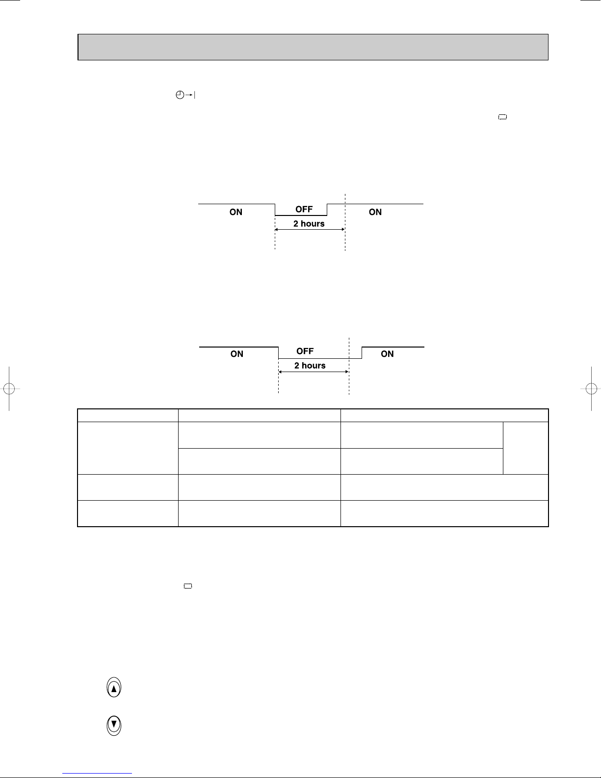
• Once the mode is fixed, the mode does not change by room temperature afterwards.
Model
COOL mode of
"I FEEL CONTROL"
DRY mode of
"I FEEL CONTROL"
HEAT mode of
"I FEEL CONTROL"
Initial room temperature Initial set temperature
26:
26: or more
25: to 26:
less than 23:
23: to 25:
24:
Initial room temperature
minus 2:
Initial room temperature
minus 2:
❈1
TOO
COOL
TOO
WARM
• Under ON-TIMER ( ) operation, mode is determined as follows.
When the system is stopped on the remote controller, and restarted within 2 hours in “I FEEL CONTROL” ( ) mode,
the system operates in previous mode automatically regardless of the room temperature.
Operation time chart
Example
Previous operation
COOL mode of
“I FEEL CONTROL”
Restart
COOL mode of
“I FEEL CONTROL”
or COOL mode
When the system is restarted after 2 hours and more, the operation mode is determined by the room temperature at
start-up of the operation.
Operation time chart
Example
Previous operation
COOL mode of
“I FEEL CONTROL”
or COOL mode
Restart
COOL or DRY or
HEAT mode of “I FEEL
CONTROL” that determined by room temperature at start-up of
the operation.
(4) The initial set temperature is decided by the initial room temperature.
❈1 When the system is restarted with the remote controller, the system operates with the previous set temperature regard-
less of room temperature at restart.
The set temperature is calculated by the previous set temperature.
(5) TEMPERATURE buttons
In “I FEEL CONTROL” ( ) mode, set temperature is decided by the microprocessor based on the room temperature.
In addition, set temperature can be controlled by TOO WARM or TOO COOL buttons when you feel too cool or too warm.
Each time TOO WARM or TOO COOL button is pressed, the indoor unit receives the signal and emits a beep tone.
• Fuzzy control
When TOO COOL or TOO WARM button is pressed, the microprocessor changes the set temperature, considering the
room temperature, the frequency of pressing TOO COOL or TOO WARM button and the user’s preference to heat or
cool. So this is called “Fuzzy control”, and works only in “I FEEL CONTROL” mode.
In DRY mode of “I FEEL CONTROL”, the set temperature doesn’t change.
…
To raise the set temperature 1~2°C
…
To lower the set temperature 1~2°C
27
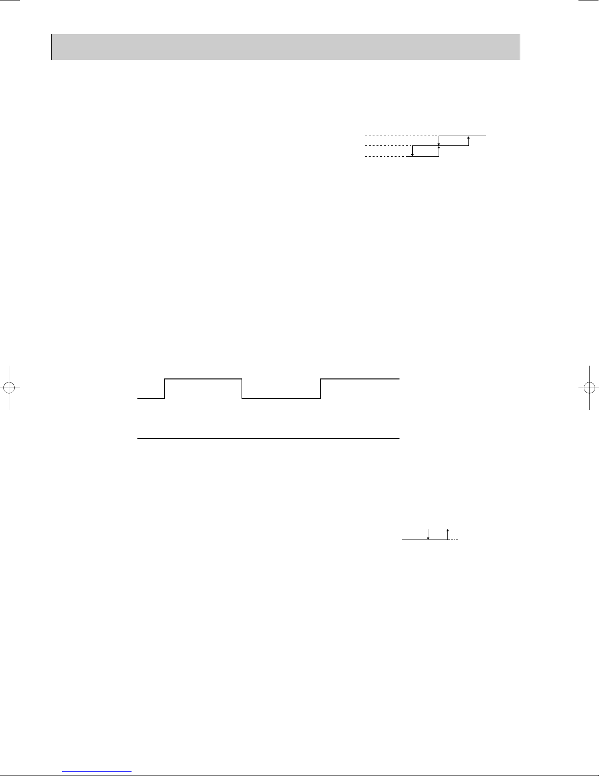
3-1-1. COOL mode of “I FEEL CONTROL”
Difference between room
temperature and set temperature
during operation
1°C 1.7°C
3°C
Outdoor fan speed
20: 22:
High
Ambient temperature
thermistor RT63 temperature
Low
1. Indoor fan speed control
Indoor fan operates at the set speed by FAN SPEED CONTROL button.
In AUTO the fan speed is as follows.
Initial temperature difference Fan Speed
Room temperature minus set temperature : 1.7 : or more
Room temperature minus set temperature : Between 1 and 1.7 :
Room temperature minus set temperature : less than 1 :
2. Coil frost prevention
① Temperature control
When the indoor coil thermistor RT12 reads 1°C or below(MSH-CA50/CB50/GA50VB) /–1°C or below(MSH-GA60VB)/
RT12 or RT13 reads 1°C or below (MSH-GA80VB), the coil frost prevention mode starts immediately.
However, the coil frost prevention doesn’t work for 5 minutes since the compressor has started.
The indoor fan operates at the set speed and the compressor stops for 5 minutes.
After that, if RT12 still reads below 1°C(MSH-CA50/CB50/GA50VB)/ –1°C(MSH-GA60VB)/ RT12 or RT13 still reads
below 1°C (MSH-GA80VB) this mode prolonged until RT12 reads over 1°C(MSH-CA50/CB50/GA50VB)/ –1°C(MSHGA60VB) / RT12 or RT13 still reads over 1°C(MSH-GA80VB).
② Time control
When the three conditions as follows have been satisfied for 1 hour and 45 minutes, compressor stops for 3 minutes.
a. Compressor has been continuously operating.
b. Indoor fan speed is Low or Med.
c. Room temperature is below 26°C.
When compressor stops, the accumulated time is cancelled and when compressor restarts, time counting starts from the
beginning.
Time counting also stops temporarily when the indoor fan speed becomes High or the room temperature exceeds
26°C. However, when two of the above conditions (b.and c.) are satisfied again. Time accumulation is resumed.
Operation chart
Example
Compressor
OFF
ON
Outdoor fan
····································High
·························Med.
·····································Low
ON
OFF
(continuously at set speed)
Indoor fan
ON
3. Outdoor fan speed control <MUH-GA80VB>
Outdoor fan speed is controlled according to the temperature of ambient temperature thermistor RT63.
Outdoor fan Low operation : When the outside temperature decreases to 20°C or less.
Until the outside temperature goes to 22°C.
Outdoor fan High operation : Until the outside temperature decreases to 20°C or less.
When the outside temperature goes to 22°C.
NOTE1 : If the temperature of RT63 reads from 20: to 22: at the air conditioner starting outdoor fan speed is High.
NOTE2 : When indoor fan speed is Low except HEAT operation mode and the outside temperature is 30: or less, the
outdoor fan operates at Low.
Outdoor fan Low operation is cancelled according to the following conditions(1 or 2):
1 When the operation is not changed and the outside temperature goes to 33: or more.
2 When the operation is changed. (Change to HEAT operation mode / Change of the indoor fan speed)
4. Discharge temperature protection <MUH-GA80VB>
The compressor is controlled by the temperature of discharge temperature thermistor RT62 for excess rise protection of
compressor discharge pressure.
• Compressor
When the temperature of discharge temperature thermistor RT62 goes to 120: or more, the compressor is turned OFF.
After 3 minutes since the compressor has been turned OFF, if the temperature of discharge temperature thermistor RT62
becomes 100: or less, the compressor is turned ON.
28
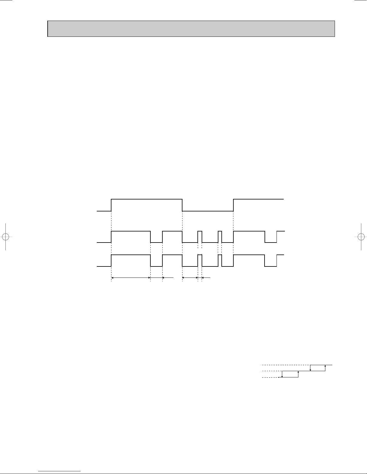
3-1-2. DRY mode of “I FEEL CONTROL”
Difference between room
temperature and set temperature
during operation
1°C 1.7°C
4°C
2°C
The system for dry operation uses the same refrigerant circuit as the cooling circuit.
The compressor and the indoor fan are controlled by the room temperature.
By such controls, indoor flow amounts will be reduced in order to lower humidity without much room temperature decrease.
1. Indoor fan speed control
Indoor fan operates at the set speed by FAN SPEED CONTROL button.
However, in AUTO fan operation, fan speed becomes Low.
2. The operation of the compressor and indoor/ outdoor fan
Compressor operates by room temperature control and time control.
Set temperature is controlled to fall 2°C from initial room temperature.
Indoor fan and outdoor fan operate in the same cycle as the compressor.
•When the room temperature is 23°C or over:
When the thermostat is ON, the compressor repeats 8 minutes ON and 3 minutes OFF.
When the thermostat is OFF, the compressor repeats 4 minutes OFF and 1 minute ON.
•When the room temperature is under 23°C.
When the thermostat is ON, the compressor repeats 2 minutes ON and 3 minutes OFF.
When the thermostat is OFF, the compressor repeats 4 minutes OFF and 1 minute ON.
Operation time chart
Example
ON
ON
Thermostat
Indoor fan
Outdoor fan
OFF
OFF
OFF
ON
ON
ON
OFF
ON
OFF
OFF
ON
OFF
ON
OFF
Compressor
3. Coil frost prevention
8 minutes
3 minutes
4 minutes
1 minute
• The operation is as same as coil frost prevention during COOL mode of “I FEEL CONTROL”.
• Indoor fan operates at the set speed and the compressor stops for 5 minutes, because protection(Coil frost
prevention) has the priority.
However, when coil frost prevention works while the compressor is not operating, its speed becomes Low.
4. Outdoor fan speed control <MUH-GA80VB>
Outdoor fan speed is as same as one of COOL mode of “I FEEL CONTROL”.
3-1-3. HEAT mode of “I FEEL CONTROL”
1. Indoor fan speed control
(1) In AUTO the fan speed is as follows.
Set temperature minus room temperature: 2 : or more·························································· High
Set temperature minus room temperature: Between 1 and 2 : ·············································· Med.
Set temperature minus room temperature: less than 1: ························································· Low
Initial temperature difference Fan speed
29
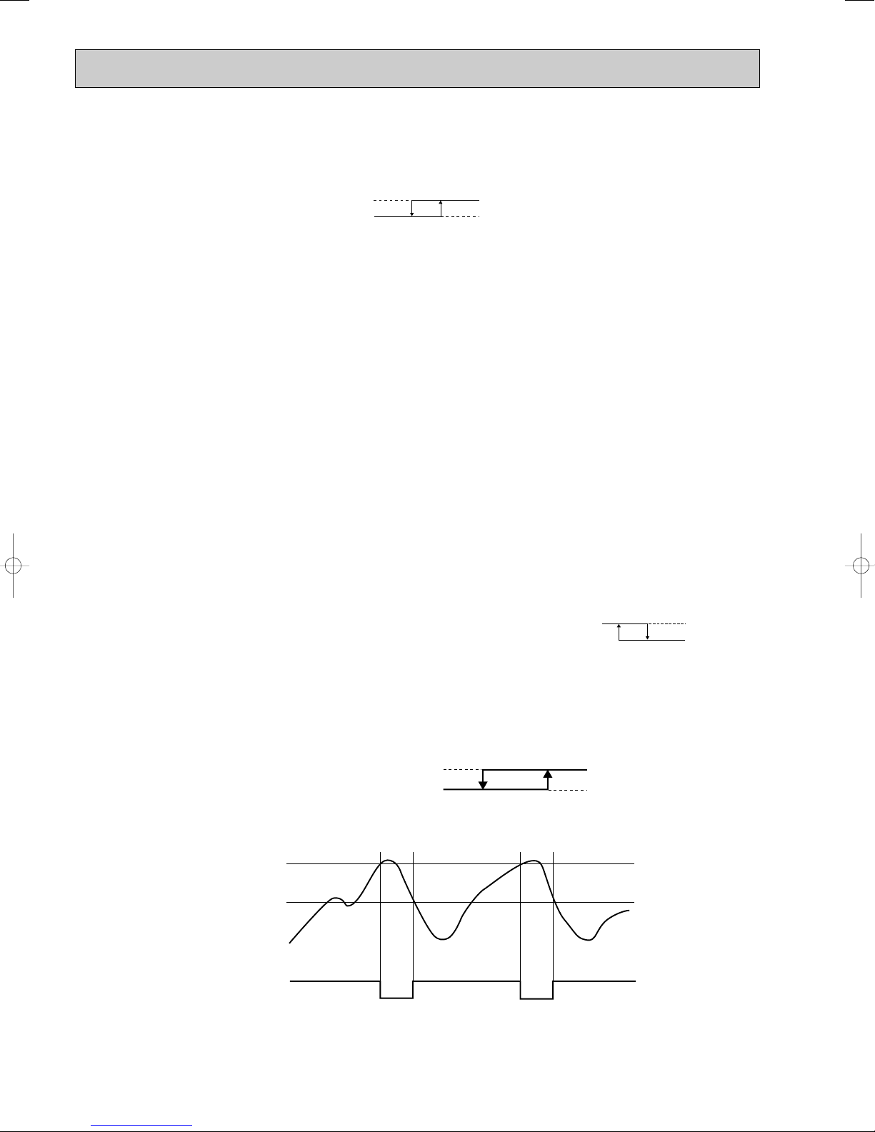
(2) Cold air prevention control
Released
Cold Air Prevention
18: 22:
Fan speed
Set speed
Very Low or stop
High pressure protection
Released
48: 52:
ON
Outdoor fan
OFF
55:
(MUH-GA50VB)
(MUH-GA60VB) 58:
Outdoor fan speed
13: 18:
High
Ambient temperature
thermistor RT63 temperature
Low
The fan runs at set speed when the indoor coil thermistor RT12 temperature exceeds 22°C. The fan operates Low when
the temperature of indoor coil thermistor RT12 is below 18°C. But the fan stops when the indoor fan operates at Very
Low and the room temperature is 15°C or less.
Indoor coil thermistor
RT12 temperature
NOTE : If the temperature of RT12 reads from 18°C to 22°C at the air conditioner starting and also after defrosting, this
control works.
(3) Warm air control
When compressor starts in heating operation or after defrosting, the fan changes the speed due to the indoor coil thermistor RT12 temperature to blow out warm air.
After releasing of cold air prevention, when the indoor coil thermistor RT12 temperature is 37°C or above, the fan speed
shifts to the set speed, and when the fan speed is changed by the remote controller, the fan speed is the set speed.
When the indoor coil thermistor RT12 temperature is less than 37°C, the fan speed is controlled by time as below.
<Time condition> <Indoor fan speed>
less than 2 minutes························Low
2 minutes to 4 minutes···················Med.
4 minutes or more··························High
The upper limit of the fan speed is the set speed.
If the thermostat turns off, this operation changes to flow soft control.
(4) Flow soft control
After the thermostat turns off, the indoor fan operates at Very Low.
NOTE : When the thermostat turns on, the fan operates at the set speed. Due to the cold air prevention control, the fan
does not start at set speed until the indoor coil thermistor RT12 reads 22°C or more.
2. Outdoor fan speed control <MUH-GA80VB>
Outdoor fan speed is controlled according to the temperature of ambient temperature thermistor RT63.
Outdoor fan Low operation : Until the outside temperature decreases to 13°C.
When the outside temperature goes to 18°C or more.
Outdoor fan High operation :When the outside temperature decreases to 13°C or less.
Until the outside temperature goes to 18°C.
3. High pressure protection
<MUH-GA50/60VB>
During heating operation, the outdoor fan motor is controlled by the temperature of indoor coil thermistor RT12 for excess
rise protection of compressor discharge pressure.
(MUH-GA50VB) Outdoor fan OFF : 52°C
Outdoor fan ON : 48°C
(MUH-GA60VB) Outdoor fan OFF : 58°C
Outdoor fan ON : 55°C
High pressure protection chart
Example
Indoor coil thermistor
RT12 temperature
(MUH-GA50VB) 52˚C
(MUH-GA60VB) 58˚C
(MUH-GA50VB) 48˚C
(MUH-GA60VB) 55˚C
Outdoor fan motor
ON
OFF
ON
OFF
Outdoor fan motor
turn OFF
Outdoor fan motor
turn ON
NOTE : During high pressure protection and for 4 minutes and 15 seconds after high pressure protection, defrosting of
outdoor heat exchanger is not detected by the defrost thermistor RT61.
30

<MUH-GA80VB>
During heating operation, the outdoor fan and the compressor are controlled by the temperature of indoor coil thermistor
RT12 for excess rise protection of compressor discharge pressure.
• Outdoor fan
When the temperature of indoor coil thermistor RT12 goes to 55: or more, the outdoor fan is turned OFF.
When the temperature of indoor coil thermistor RT12 becomes to 52: or less, the outdoor fan is turned ON.
• Compressor
When the temperature of indoor coil thermistor RT12 goes to 75: or more, the compressor is turned OFF.
3 minutes after the compressor is turned OFF and if the temperature of indoor coil thermistor RT12 becomes 75: or less,
the compressor is turned ON.
NOTE : During the high pressure protection and for 10 seconds after high pressure protection, defrosting of outdoor heat
exchanger is not detected by the defrost thermistor RT61.
4. Discharge temperature protection <MUH-GA80VB>
Discharge temperature protection is as same as during COOL mode of “I FEEL CONTROL”.
5. Defrosting
Defrosting of outdoor heat exchanger is controlled by deicer P.C. board, with detection by the defrost thermistor RT61.
(1) Starting conditions of defrost
When all conditions of a) ~ c) are satisfied, the defrosting operation starts.
a) Under the heat operation, the compressor cumulative operation time exceeds 40 minutes without the defrosting opera-
tion working.
b) The defrost thermistor RT61 reads -3°C or less.
c) After releasing the high pressure protection 4 minutes and 15 seconds(MUH-GA50/GA60VB) / 10 seconds
(MUH-GA80VB) have elapsed.
(2) Releasing conditions of defrost
When the condition d) or e) is satisfied, the defrosting operation stops.
d) The defrost thermistor RT61 reads 3°C(MUH-GA50/GA60VB)/ 13°C(MUH-GA80VB) or more.
e) The defrosting time exceeds 10 minutes.
(3) Defrosting time chart
Defrost thermistor RT61
13: or more
3: or more
(MUH-GA80VB)
(MUH-GA50/GA60VB)
-3: or less
Outdoor 52C
contactor(Compressor)
ON
OFF
X62
(R.V. coil)
SR61
Outdoor fan
Defrost
counter
Indoor fan
ON
OFF
ON
OFF
ON
OFF
ON
Very Low
15 seconds
30 seconds
Max. 10 minutes
NOTE
30 seconds
5 seconds
OFF
Indoor vane
Horizontal
Set position
NOTE: • When the indoor coil thermistor RT12 reads above 18°C, indoor fan operates at Very Low for 30 seconds.
• When the indoor coil thermistor RT12 reads 18°C or less, the indoor fan stops.
31

High
Rotational frequency
High
time
Med.
Low
3-2. COOL ( ) OPERATION
(1) Press OPERATE/STOP (ON/OFF) button.
OPERATION INDICATOR lamp of the indoor unit turns on with a beep tone.
(2) Select COOL mode with OPERATION SELECT
button.
(3) Press TEMPERATURE buttons.
(TOO WARM or TOO COOL button) to select
the desired temperature.
The setting range is 16 ~ 31°C.
✻ Indoor fan continues to operate regardless of
thermostat’s OFF-ON at set speed.
✻ Coil frost prevention is as same as COOL
mode of “I FEEL CONTROL”.
3-3. DRY ( ) OPERATION
(1) Press OPERATE/STOP (ON/OFF) button.
OPERATION INDICATOR lamp of the indoor
unit turns on with a beep tone.
(2) Select DRY mode with OPERATION SELECT
button.
(3) The microprocessor reads the room tempera-
ture and determines the set temperature. Set
temperature is as shown on the right chart.
Thermostat (SET TEMP.)does not work.
The other operations are same as DRY mode of
“I FEEL CONTROL”.
(4) DRY operation will not function when the room
temperature is 13°C or below.
3-4. HEAT ( ) OPERATION
(1) Press OPERATE/STOP (ON/OFF) button.
OPERATION INDICATOR lamp of the indoor unit turns on with a beep tone.
(2) Select HEAT mode with OPERATION SELECT button.
(3) Press TEMPERATURE buttons (TOO WARM or TOO COOL button) to select the desired temperature.
The setting range is 16 ~ 31°C.
(4) Indoor fan speed control, high pressure protection, defrosting, R.V. coil control are the same as HEAT mode of “I FEEL
CONTROL”.
3-5. INDOOR FAN MOTOR CONTROL
(1) Rotational frequency feedback control
The indoor fan motor is equipped with a rotational frequency sensor, and outputs signal to the microprocessor to
feedback the rotational frequency. Comparing the current rotational frequency with the target rotational frequency
(High, Med., Low), the microprocessor controls SR141 and adjusts fan motor electric current to make the current rota-
tional frequency close to the target rotational frequency. With this control, when the fan speed is switched, the rotational
frequency changes smoothly.
(2) Fan motor lock-up protection
When the rotational frequency feedback signal has not output for 12 seconds, (or when the microprocessor cannot
detect the signal for 12 seconds) the fan motor is regarded locked-up. Then the electric current to the fan motor is shut
off. 3 minutes later, the electric current is applied to the fan motor again. During the fan motor lock-up, the OPERATION
INDICATOR Indicator lamp flashes on and off to show the fan motor abnormality.
32

3-6. AUTO VANE OPERATION
Released
Cold Air Prevention
24: 28:
Angle 1
Horizontal vane
Set position
1. Horizontal vane
(1) Vane motor drive
These models are equipped with a stepping motor for the horizontal vane. The rotating direction, speed, and angle of
the motor are controlled by pulse signals (approx. 12V) transmitted from indoor microprocessor.
(2) The horizontal vane angle and mode change as follows by pressing the VANE button.
AUTO
12
Horizontal
34 5
Middle Downward Swing
(3) Positioning
The vane presses the vane stopper once to confirm the standard position and then moves to the set angle.
Confirming of standard position is performed in case of follows.
(a) When the power supply turns ON.
(b) When the operation starts or finishes (including timer operation).
(c) When the test run starts.
(d) When the vane control is changed AUTO to MANUAL(except SWING).
(e) When SWING is finished (including ECONO COOL).
(f) When multi-standby starts or finishes.
(4) VANE AUTO ( ) mode
The microprocessor automatically determines the horizontal vane angle and operation to make the optimum room tem-
perature distribution.
COOL and DRY operation
Vane angle is fixed to Angle 1.
HEAT operation
Vane angle is fixed to Angle 4.
(5) STOP (operation OFF) and ON-TIMER standby
When the following cases occur, the horizontal vane returns to the closed position.
(a) When OPERATE/STOP (ON/OFF) button is pressed (POWER OFF).
(b) When the operation is stopped by the emergency operation.
(c) When ON-TIMER is on standby.
(6) Dew prevention
During COOL or DRY operation at Vane Angle 4 or 5 when the compressor cumulative operation time of compressor
exceeds 1 hour, the vane angle automatically changes to Angle 1 for dew prevention.
(7) SWING MODE ( )
By selecting SWING mode with VANE button, the horizontal vane swings vertically. The remote controller displays “ ”.
SWING mode is cancelled when VANE button is pressed once again.
(8) Cold air prevention in HEAT operation
When any of the following conditions occurs in HEAT operation, the vane angle changes to Angle 1
automatically to prevent cold air blowing on users.
① Compressor is not operating.
➁ Defrosting is performed.
➂ Indoor coil thermistor RT12 reads 24: or below.
➃ Indoor coil thermistor RT12 temperature is raising from 24°C or below, but it does not exceed 28:.
Indoor coil thermistor RT12 temperature
NOTE1: If the temperature of RT12 reads from 24: to 28: at the air conditioner starting, this control works.
NOTE2: When 2 or more indoor units are operated with multi outdoor unit, even if any indoor unit turns thermostat off,
this control doesn’t work in the indoor unit.
33

COOL / DRY HEAT
Fan speed : Faster
Solid arrow : When LONG mode is used.
Dotted arrow : When LONG mode is not used.
(9) ECONO COOL ( ) operation (ECONOmical operation)
When ECONO COOL button is pressed in COOL mode, set temperature is automatically set 2°C higher.
Also the horizontal vane swings in various cycle according to the temperature of indoor heat exchanger(Tp(w 1)).
SWING operation makes you feel cooler than set temperature. So, even though the set temperature is higher, the air
conditioner can keep comfort. As a result, energy can be saved.
ECONO COOL operation is cancelled when ECONO COOL button is pressed once again or VANE button is pressed or
LONG button is pressed or change to other operation mode.
NOTE : ECONO COOL operation does not work in COOL mode of “I FEEL CONTROL”.
<SWING operation>
w 1 Tp : • Value of RT12 (MSH-CA50/GA50/GA60VB)
• Minimum value of indoor coil thermistor (main) RT12 and indoor coil thermistor (sub) RT13 (MSH-GA80VB)
In swing operation of ECONO COOL operation mode, the initial air flow direction is adjusted to “Horizontal”.
According to the temperature of indoor coil thermistor Tp
(w 1) at starting of this operation, next downward blow time is
decided. Then when the downward blow has been finished, next horizontal blow time is decided.
For initial 10 minutes the swing operation is performed in table G~H for quick cooling.
Also, after 10 minutes when the difference of set temperature and room temperature is more than 2:, the swing operation is performed in table D~H for more cooling.
The air conditioner repeats the swing operation in various cycle as follows.
Temperature of Tp(w 1)
A
B
C
D
E
F
G
H
15°C to 17°C
17°C to 18°C
18°C to 20°C
20°C to 21°C
21°C to 22°C
22°C to 24°C
more than 24°C
15°C or less
Downward blow time
(second)
2
5
8
11
14
17
20
23
Horizontal blow time
(second)
23
20
17
14
11
8
5
2
(10) LONG MODE ( )
By pressing LONG button indoor fan speed becomes faster than setting fan speed on the remote controller, and the hor-
izontal vane moves to the position for LONG mode. The remote controller displays “”. LONG mode is cancelled
when LONG button is pressed once again or VANE button is pressed or ECONO COOLbutton is pressed in COOL
mode.
• In the following example, the vertical vane is set to (front.).
34

2. Vertical vane
COOL and DRY
HEAT
About 100-
About 150-
Horizontal AIR FLOW blowing range
(1) Vane motor drive
These models are equipped with a stepping motor for the vertical vane. The rotating direction, speed, and angle of the
motor are controlled by pulse signals (approx. 12V) transmitted from microprocessor.
(2) The vertical vane angle and mode change as follows by pressing the WIDE VANE button.
23
45SWING
61
(3) Positioning
The vane is once pressed to the vane stopper to confirm the standard position and then set to the desired angle.
Confirming of standard position is performed in case of follows.
(a) When OPERATE/STOP(ON/OFF) button is pressed (POWER ON/OFF).
(b) When SWING is started or finished.
(c) When the power supply turns ON.
(4) SWING MODE ( )
By selecting SWING mode with WIDE VANE button, the vertical vane swings horizontally. The remote controller displays
“”. The vane moves right and left in the width of Angle 4 repeatedly.
(5) WIDE MODE ( )
By selecting WIDE mode with WIDE VANE button, indoor fan speed becomes faster than setting fan speed on the
remote controller (W). The remote controller displays “”.
NOTE : The position of vane angle 3, angle 4 and angle 5 are different in COOL operation and HEAT operation.
W Indoor fan speed becomes faster than setting fan speed on the remote controller even when or is
selected.
3-7. TIMER OPERATION
1. How to set the timer
(1) Press OPERATE/STOP (ON/OFF) button to start the air conditioner.
(2) Check that the current time is set correctly.
NOTE : Timer operation will not work without setting the current time. Initially “AM0:00” blinks at the current time display of
TIME MONITOR, so set the current time correctly with CLOCK SET button.
(3) Press ON/OFF TIMER buttons to select the operation.
“ON-TIMER” button... AUTO START operation (ON timer)
“OFF-TIMER” button... AUTO STOP operation (OFF timer)
(4) Press HR. and MIN. button to set the timer. Time setting is 10-minute units.
HR. and MIN. button will work when “” or “” mark is flashing.
These marks disappear in 1 minute.
After setting the ON timer, check that OPERATION INDICATOR lamp of the indoor unit lights.
NOTE1 : Be sure to place the remote controller at the position where its signal can reach the air conditioner even during
TIMER operation, or the set time may deviate within the range of about 10 minutes.
NOTE2 : Reset the timer in the following cases, or the set time may deviate and other malfunctions may occur.
• Apower failure occurs.
•The circuit breaker functions.
35

EMERGENCY OPERATION switch
Press once <Cool>
Press again <Heat>
Press once again <Stop>
OPERATION INDICATOR lamp
• The following indication applies regardless of
shape of the indicator.
Lighted
Not Lighted
2. Cancel
PM
AM
PM
PM
TIMER setting can be cancelled with the ON/OFF TIMER buttons.
To cancel ON timer, press “ON-TIMER” button.
To cancel OFF timer, press “OFF-TIMER” button.
TIMER is cancelled and the display of set time disappears.
PROGRAM TIMER
• OFF timer and ON timer can be used in combination.
• “” and “” display shows the order of OFF timer and ON timer operation.
(Example 1) The current time is 8:00 PM.
The unit turns off at 11:00 PM, and on at 6:00 AM.
(Example 2) The current time is 11:00 AM.
The unit turns on at 5:00 PM, and off at 9:00 PM.
NOTE : TIMER setting will be cancelled by power failure or breaker functioning.
3-8. EMERGENCY / TEST OPERATION
In case of test run operation or emergency operation, use EMERGENCY OPERATION switch on the front of the indoor
unit. Emergency operation is available when the remote controller is missing, has failed or the batteries of remote controller run down. The unit will start and OPERATION INDICATOR lamp will light.
The first 30 minutes of operation is the test run operation. This operation is for servicing. The indoor fan speed runs at
High speed and the system is in continuous operation. (The thermostat is ON.)
After 30 minutes of test run operation, the system shifts to EMERGENCY COOL / HEAT MODE with a set temperature of
24°C.
The fan speed shifts to Med. speed.
The coil frost prevention works even in emergency operation, and defrosting too.
In the test run or emergency operation, the horizontal vane operates in VANE AUTO ( ) mode.
Emergency operation continues until EMERGENCY OPERATION switch is pressed once or twice or the unit receives any
signal from the remote controller. In case of latter, normal operation will start.
NOTE : Do not press EMERGENCY OPERATION switch during normal operation.
36

3-9. EXPANSION VALVE CONTROL (LEV CONTROL) <MUH-GA80VB>
Controlled range
Basic specification
Minimum : 54 pulse, Maximum : 500 pulse
Drive speed
30 ~ 90 pulse / second
Opening set
The setting is always in opening direction.
(To close the LEV, it is closed to the pulse smaller than the one which is
set finally. Then the LEV is opened to the final setting pulse.)
Stop of indoor unit
Opening in stop : 150 pulse ➔ LEV opening is set to becomes 500 pulse
after 3 minutes passed.
Remote controller ON
LEV positioning (LEV is closed completely at once)
Power ON (Breaker ON)
LEV is positioned. However, afterwards, LEV is not positioned at the first
remote controller ON.
Approximate for 2 minutes since
compressor has started.
Opening is set by the initial opening.
(Initial opening is set according to each operation modes and
outer temperature conditions.)
From approximate 2 minutes to
approximate 13 minutes
(for 11 minutes) since compressor
has started.
Opening is set by standard opening.
(Standard opening is set according to each operation modes and
outer temperature conditions.)
After 13 minutes passed since
compressor has started.
LEV opening is corrected to be once every 2 minutes so that discharge
temperature becomes the target discharge temperature.
(When the discharge temperature is lower than target one : LEV is corrected in
closed direction, when the discharge temperature is higher than target one :
LEV is corrected in opening direction.)
At thermostat OFF
Opening in stop : 150 pulse ➔ LEV is set to the initial opening after about
3 minutes passed.
At thermostat ON
Same as the starting of compressor operation
At remote controller OFF
Opening in stop : 150 pulse ➔ LEV is set so that the opening is opened
completely at the speed of 4 pulse every 5 seconds in opening after about
3 minutes passed.
General operation
Rank
Ta (:)
more than Tb+10
Tb+5 to Tb+10
Tb+2 to Tb+5
Tb-2 to Tb+2
Tb-5 to Tb-2
Tb-10 to Tb-5
less than Tb-10
100 pulse or less
Cooling / Heating
5
2
1
0
-1
-2
-5
NOTE : Discharge temperature : Ta, Target discharge temperature : Tb
100 pulse or more
Cooling / Heating
20
10
2
0
-2
-5
-10
Opening immediately before having stopped last time
LEV (Expansion valve) is controlled by “Thermostat ON” commands given from the unit.
(1) LEV opening correction by discharge temperature
The LEV opening is corrected according to the temperature difference between target discharge temperature (Tb) and
actual discharge temperature (Ta).
1 The LEV correction is used properly for two kinds according to the LEV opening status at operation off.
37

2 When the temperature difference RT between indoor coil thermistor (main) RT12 and indoor coil thermistor (sub)
Ta (:)
more than Tb+10
Tb+5 to Tb+10
Tb+2 to Tb+5
Tb-2 to Tb+2
Tb-5 to Tb-2
Tb-10 to Tb-5
less than Tb-10
less than 2:
20
10
2
0
-2
-5
-10
NOTE : Discharge temperature : Ta, Target discharge temperature : Tb
3: or more
60
20
2
0
-2
-5
-10
RT
2: or more and less than 3:
60
20
2
0
-2
-5
-10
Tb (:)
HEAT
COOL (Normal)
COOL ( RT is less than 2:, or RT is 2:or more and less than 3:.)
COOL ( RT is 3 :or more.)
NOTE : Target discharge temperature : Tb
85
80
70
65
Operation mode
NOTE : Opening increases and decreases to be in the target discharge temperature during operation.
Opening
completely
Positioning
Power ON
Initial opening
Standard opening
Remote
controller
ON
➔
Operation
Thermostat
OFF
Standard opening
Thermostat
ON
Opening in stop
Operation
Opening in stop
Remote
controller
OFF
Opening
completely
Remote
controller
ON
➔
Positioning
Standard opening
Operation
Time
LEV opening
Initial opening
Initial opening
Open
Close
(Second)
(A)
WITH SOFT START RELAY
WITHOUT SOFT START RELAY
RT13 in the indoor unit is 2: or more for a fixed time at cool or dry operation, the target discharge temperature is
changed. After the temperature is changed, when temperature difference RT is 3: or more, the target temperature
is changed again. The LEV opening is controlled based on the changed target discharge temperature and the temperature difference RT.
The target discharge temperature (Tb) is set according to the operation mode or the unit status as follows.
NOTE : When the discharge temperature (Ta) is 50: or less on the cool operation, or is 49: or less on heat operation,
LEV opening is set in 54 pulse.
When this state continues for 20 minutes, the compressor is stopped and restarts in 3 minutes.
When the compressor is stopped, the indoor unit indicates the abnormality of refrigerant system and stops.
(OPERATION INDICATOR lamp is 10-time flashing on and off.)
(2) LEV time chart
3-10. FUNCTION OF SOFT START RELAY
Soft start relay will chop some starting current.
Starting current is reduced as shown in the following figures.
38

4
Approx.
2 :
or more
Difference
between target
temperature
and room
temperature
Approx.
2 :
or less
This shows that the
air conditioner is
operating to reach
the target temperature.
Please wait until the
target temperature is
obtained.
This shows that the
room temperature is
approaching the
target temperature.
Operation state
Indication
Lighted
Not lighted
•The following indication applies regardless of shape of the indicator.
Operation Indicator
Mode
COOL mode of
"I FEEL CONTROL"
DRY mode of
"I FEEL CONTROL"
HEAT mode of
"I FEEL CONTROL"
Initial room temperature
25: or more
23: to 25:
less than 23:
ON/OFF
FAN
TOO
WARM
TOO
COOL
VANE
MODE
ECONO COOL
STOP
START
HR.
MIN.
AM PM
CLOCK
˚C
AM
RESET CLOCK
I FEEL
COOL
DRY
AUTO
HEAT
OPERATION SELECT button
FAN SPEED CONTROL button
OFF-TIMER button
HR. button
MIN. button
(TIME SET button)
ON-TIMER button
RESET button
ECONO COOL button
VANE CONTROL button
CLOCK SET button
ON/OFF
TOO
COOL
PM
AM
TOO
WARM
Signal transmitting section
Operation display section
OPERATE /STOP
(ON /OFF) button
TEMPERATURE buttons
Indication of remote controller model
is on back
MSZ-CA MICROPROCESSOR CONTROL
MSZ-CA25VB MUZ-CA25VB
MSZ-CA35VB MUZ-CA35VB
WIRELESS REMOTE CONTROLLER
INDOOR UNIT DISPLAY SECTION
Operation Indicator lamp
The operation indicator at the right side of the indoor unit indicates the operation state.
Once the operation mode is set, the same operation mode
can be repeated by simply turning OPERATE/STOP
(ON/OFF) button ON.
Indoor unit receives the signal with a beep tone.
When the system turns off, 3-minute time delay will operate
to protect system from overload and compressor will not
restart for 3 minutes.
4-1. “I FEEL CONTROL” ( ) OPERATION
1. Press OPERATE/STOP(ON/OFF) button on the remote
controller. OPERATION INDICATOR lamp of the indoor
unit will turn on with a beep tone.
2. Select “I FEEL CONTROL”( ) mode with OPERATION
SELECT button.
3. The operation mode is determined by the room temperature at start-up of the operation.
39

• Once the mode is fixed, the mode does not change by room temperature afterwards.
Model
COOL mode of
"I FEEL CONTROL"
DRY mode of
"I FEEL CONTROL"
HEAT mode of
"I FEEL CONTROL"
Initial room temperature Initial set temperature
26:
26: or more
25: to 26:
less than 23:
23: to 25:
24:
Initial room temperature minus 2:
Initial room temperature minus 2:
❈1
TOO
COOL
TOO
WARM
• Under ON-TIMER ( ) operation, mode is determined as follows.
When the system is stopped on the remote controller, and restarted within 2 hours in “I FEEL CONTROL” ( ) mode, the
system operates in previous mode automatically regardless of the room temperature.
Operation time chart
Example
Previous operation
COOL mode of
“I FEEL CONTROL” or
Restart
COOL mode of “I FEEL
CONTROL”
COOL mode
When the system is restarted after 2 hours and more, the operation mode is determined by the room temperature at
start-up of the operation.
Operation time chart
Example
Previous operation
COOL mode of “I FEEL
CONTROL” or COOL
mode
Restart
COOL or DRY or
HEAT mode of “I
FEEL CONTROL”
that determined
by room temperature at start-up of
the operation.
4. The initial set temperature is decided by the initial room temperature.
❈1 When the system is restarted with the remote controller, the system operates with the previous set temperature regard-
less of the room temperature at restart.
The set temperature is calculated by the previous set temperature.
5. TEMPERATURE buttons
In “I FEEL CONTROL” ( )mode, set temperature is decided by the microprocessor based on the room temperature.
In addition, set temperature can be controlled by TOO WARM or TOO COOL buttons when you feel too cool or too warm.
Each time TOO WARM or TOO COOL button is speed, the indoor unit receives the signal emits a beep tone.
• Fuzzy control
When TOO COOL or TOO WARM button is pressed, the microprocessor changes the set temperature, considering
the room temperature, the frequency of pressing TOO COOL or TOO WARM button and the user’s preference to heat
or cool. So this is called “Fuzzy control”, and works only in “I FEEL CONTROL” mode.
In DRY mode of “I FEEL CONTROL”, the set temperature doesn’t change.
…
To raise the set temperature 1 ~ 2:
…
To lower the set temperature 1 ~ 2:
40

4-1-1. COOL mode of “I FEEL CONTROL”
1. Thermostat control
Thermostat is ON or OFF by difference between room temperature and set temperature
Initial temperature difference Thermostat
Room temperature minus set temperature : 0.3 : or more················································ON
Difference between room
temperature and set temperature during operation.
Set temperature
Room temperature minus set temperature : less than -0.3 :············································OFF
2. Indoor fan speed control
-0.3 :
Indoor fan operates continuously at the set speed by FAN SPEED CONTROL button
regardless of the thermostat’s OFF-ON.
In AUTO the fan speed is as follows.
Initial temperature difference
Fan speed
Difference between room
temperature and set temperature during operation ( T)
Room temperature minus set temperature : 1.7 : or more·············································High
Room temperature minus set temperature : Between 1 and 1.7 :·································Med.
Room temperature minus set temperature : less than 1 :··············································Low
ww
In case that T has been any following condition for 30 minutes, the value in the parentheses is applied.
1
:
(0 :)W
a. Fan speed is Auto Low, and T is 1 : or more.
b. Fan speed is Auto Med., and T is 1.7 : or more.
3. Coil frost prevention
1 Temperature control
The operational frequency of the compressor is controlled based on the temperature of the indoor coil thermistor.
Temperature of indoor coil thermistor
8°C or more
6°C to 8°C
3°C to 6°C
Lower at the rate of 3 Hz / 90 seconds
Operation frequency
Normal (variable)
Fixed
Lower at the rate of 6 Hz / 90 seconds
3°C or less
Compressor is turned OFF for 5 minutes when temperature of
indoor coil thermistor continues 3°C or less for 5 minutes or more.
0.3 :
1.7
:
(0.7 :)W
3
:
(1.7 :)W
The indoor fan maintains the actual speed of the moment.
2 Time control
When the three conditions as follows have been satisfied for 1 hour and 45 minutes, compressor stops for 3 minutes.
The indoor fan operates at set speed.
a. Compressor has been continuously operating.
b. Indoor fan speed is Low or Med.
c. Room temperature is below 26:.
When compressor stops, the accumulated time is cancelled. When compressor restarts, time counting starts from the
beginning.
Time counting also stops temporarily when the indoor fan speed becomes High or the room temperature exceeds 26:.
However, when two of the above conditions(b and c.) are satisfied again. Time accumulation is resumed.
4. Low outside temperature operation
When the ambient temperature thermistor RT65 reads 17: or less, the operation mode moves to cool operation in low outside temperature from normal cool operation.
Each outdoor actuator (compressor/ fan/ LEV) is operated in the exclusive control, which is different from one of normal
cool operation.
Especially fan motor doesn’t operates continuously to maintain sufficient cooling capacity.
(1) Outdoor fan control
Outdoor unit (compressor) operates with outdoor fan OFF basically.
But any of following conditions is satisfied, the outdoor fan turns ON for about 5 seconds.
a). the defrost thermistor RT61 reads 50: or more.
b). the fin temperature thermistor RT64 reads 60: or more.
(2) LEV (expansion valve) control
In normal cool operation the opening degree of expansion valve is corrected according to the discharge temperature
(RT62). But in this mode it is fixed to the value corresponding to the operation frequency of compressor.
(3) Dew drop prevention
When the ambient temperature thermistor RT65 reads -13: or less, as coil frost or dew drop from indoor unit may
occur, the compressor turns OFF with the outdoor fan ON for prevention of them.
NOTE: This control can be released by cut of the jumper line JG on the outdoor inverter P.C. board.
Be sure to cut it since user accepts that maker can’t be responsible for coil frost or dew drop from indoor unit.
(4) Outside temperature detecting control
In this mode to detect the exact outside temperature the compressor turns OFF with the outdoor fan ON for 3 minutes
once 1 hour.
41

4-1-2. DRY mode of “I FEEL CONTROL”
The system for dry operation uses the same refrigerant circuit as the cooling circuit.
The compressor and the indoor fan are controlled by the room temperature.
By such controls, indoor flow amounts will be reduced in order to lower humidity without much room temperature decrease.
Difference between room
1. Thermostat control
Thermostat is ON or OFF by difference between room temperature and set temperature.
Initial temperature difference Thermostat
temperature and set temperature during operation
Set temperature
Room temperature minus set temperature : 0.3 : or more················································ON
Room temperature minus set temperature : less than -0.3 :············································OFF
-0.3 :
0.3 :
2. Indoor fan speed control
Indoor fan operates at the set speed by FAN SPEED CONTROL button.
When thermostat OFF (compressor OFF) fan speed becomes Very Low.
3. The operation of the compressor and indoor fan/ outdoor fan
Compressor operates by temperature control and time control.
1 Set temperature is controlled to fall 2°C from initial room temperature.
2 Operational frequency of compressor during operation is fixed to 30Hz.
4. Coil frost prevention
Coil frost prevention is as same as COOL mode of “I FEEL CONTROL”. (4-1-1.3.)
The indoor fan maintains the actual speed of the moment. However, when coil frost prevention works while the compressor
is not operating (= indoor fan speed Very Low), it’s speed becomes the set speed.
5. Low outside temperature operation
Low outside temperature operation is as same as COOL mode of “I FEEL CONTROL”. (4-1-1.4.)
4-1-3. HEAT mode of “I FEEL CONTROL”
Difference between room
temperature and set tem-
1. Thermostat control
perature during operation
Thermostat is ON or OFF by difference between room temperature and set temperature.
Initial temperature difference Thermostat
Set temperature
Room temperature minus set temperature : less than -0.3 :··············································ON
Room temperature minus set temperature : 0.3 : or more·················································OFF
-0.3 : 0.3 :
2. Indoor fan speed control
(1) Indoor fan operates at the set speed by FAN SPEED CONTROL button.
In Auto the fan speed is as follows.
Initial temperature difference
Set temperature minus room temperature: 2 :or more
Set temperature minus room temperature:
Between 1 and 2 : ·····································
Set temperature minus room temperature: less than 1
··················································· High
:··················································
Fan speed
Med.
Low
Difference between room
temperature and set temperature during operation
2 :
1 :
1.7 :
4 :
(2) Cold air prevention control
1 When the compressor is not operating,
(1) if the temperature of indoor coil thermistor RT12 is 0°C or less, the fan stops.
(2) if the temperature of indoor coil thermistor RT12 is more than 0°C, the fan operates at Very Low.
2 When the compressor is operating,
(1) if the temperature of RT12 is 40°C or more, the fan operates at set speed.
(2) if the temperature of RT12 is less than 40°C and
(1) if heating operation starts after defrosting, the fan stops.
(2) if the temperature of room temperature thermistor RT11 is 15°C or less, the fan stops.
(3) if the temperature of room temperature thermistor RT11 is more than 15°C, the fan operates at Very Low.
NOTE : When 3 minutes have passed since the compressor started operation, this control is released regardless of the
temperature of RT12.
42

Compressor
OFF
ON
Fan
Very Low
Set speed
<Time condition>
<Indoor fan speed>
less than 2 minutes Low
2 minutes to 4 minutes Med.
more than 4 minutes High
(3) Warm air control
When the following conditions of a) ~ b) are satisfied, warm air control works.
a) when cold air prevention has been released after the compressor started operation
b) when defrosting has been finished
When warm air control works, the fan speed changes from Low as follows to blow out warm air gradually.
When every 2 minutes have passed
(1) if the temperature of RT12 is 22°C or more, the indoor fan speed is up by 1 step.
(2) if the temperature of RT12 is 18°C to 22°C, the indoor fan speed is continued with the present speed.
(3) if the temperature of RT12 is less than 18°C, the indoor fan speed is down by 1 step.
Gradation of fan speed in initial (example)
The upper limit of the fan speed in MANUAL is the set speed.
The upper limit of the fan speed in AUTO is the speed decided by indoor fan speed control.
When the temperature of RT12 has been 37°C or more, or when the set speed has been changed, this control is
released and the fan speed is the set speed.
(4) Flow soft control
When the thermostat (compressor) is off, the indoor fan operates as follows.
NOTE : When the thermostat(compressor) turns ON, the fan will operate
at set speed. But until cold air prevention and warm air control is
released, the fan speed follow them.
3. High pressure protection
In HEAT operation the indoor coil thermistor detects the temperature of the indoor heat exchanger. The compressor operational frequency is controlled to prevent the condensing pressure from increasing excessively.
4. Overload starting
When the room temperature thermistor RT11 reads 18°C or more, the compressor runs with its maximum frequency regulated for 10 minutes after the start-up.
5. Defrosting
(1) Starting conditions of defrosting
When the following conditions a) ~ c) are satisfied, the defrosting starts.
a) The defrost thermistor reads -3°C or less.
b) The cumulative operation time of the compressor has reached any of the set valuesw (40, 45, 55, 65, 75, 85, 95, 105,
115, 125 minutes).
c) More than 5 minutes have passed since the start-up of the compressor.
w Set value of compressor operation time(hereinafter referred to as defrost interval)
This is decided by the temperature of defrost thermistor and ambient temperature thermistor, the previous defrosting
time. For example, the first defrost interval is 40 minutes long, and the second is 45 minutes long. The third and sub-
sequent intervals are set to be longer, and less frequent, depending on defrosting time.
The third and subsequent defrost intervals follow any of the three patterns …5 or 10 to 20 minutes longer, the same,
or 5 or 10 to 20 minutes shorter compared with the previous defrost interval … with the longest 125 minutes and the
shortest 40 minutes.
(2) Releasing conditions of defrosting
Defrosting is released when any of the following conditions is satisfied:
a) The defrost thermistor continues to read 5°C or more for 10 seconds.
b) Defrosting time has exceeded 10 minutes.
c) Any other mode than HEAT mode is set during defrosting.
43

Time chart of defrosting in HEAT mode (reverse type)
set position
set speed
set position
set speed
Indoor fan
Compressor normal
Outdoor fan
R.V. coil
(21S4)
OFF (COOL)
OFF
Maximum frequency
horizontal
Horizontal vane
Very Low (temperature of indoor coil thermistor > 18:)
30
seconds
30
seconds
30
seconds
5 seconds 5 seconds
40
seconds
OFF
OFF
OFF
ON (HEAT)
ON ON
ON (HEAT)
<indoor unit>
<outdoor unit>
4-2. AUTO CHANGE OVER ··· AUTO MODE OPERATION
1. Mode selection
Once desired temperature is set, unit operation is switched automatically between COOL and HEAT operation.
(1) Initial mode
At first indoor unit operates only indoor fan with outdoor unit OFF for 3 minutes to detect present room temperature.
Following the conditions below, operation mode is selected.
1 If the room temperature thermistor RT11 reads more than set temperature, COOL mode is selected.
2 If the room temperature thermistor RT11 reads set temperature or less, HEAT mode is selected.
(2) Mode change
In case of the following conditions the operation mode is changed.
1 COOL mode changes to HEAT mode when 15 minutes have passed with the room temperature 2 degrees below the
set temperature.
2 HEAT mode changes to COOL mode when 15 minutes have passed with the room temperature 2 degrees above the
set temperature.
In the other cases than the above conditions, the present operation mode is continued.
NOTE1: Mode selection is performed when multi standby (refer to NOTE2) is released and the unit starts operation with
ON-timer.
NOTE2: If two or more indoor units are operating in multi system, there might be a case that the indoor unit, which is
operating in AUTO ( ), cannot change over the other operating mode (COOL HEAT) and becomes a
state of standby.
(3) Indoor fan control/ Vane control
As the indoor fan speed and the horizontal vane position depend on the selected operation mode, when the operation
mode changes over, they change to the exclusive ones.
44

35
30
25
20
15
10
:
10 15 20 25 30 35
Set temperature
Initial room temperature
Set temperature and
initial room temperature in dry mode
:
4-3. COOL ( ) OPERATION
(1) Press OPERATE/STOP(ON/OFF) button.
OPERATION INDICATOR lamp of the indoor unit turns on with a beep tone.
(2) Select COOL mode with OPERATION SELECT button.
(3) Press TEMPERATURE buttons (TOO WARM or TOO COOL button)to select the desired temperature.
The setting range is 16 ~ 31°C
1. Thermostat control
Thermostat control is as same as COOL mode of “I FEEL CONTROL”.(4-1-1.1.)
2. Indoor fan speed control
Indoor fan speed control is as same as COOL mode of “I FEEL CONTROL”.(4-1-1.2.)
3. Coil frost prevention
Coil frost prevention is as same as COOL mode of “I FEEL CONTROL”.(4-1-1.3.)
4. Low outside temperature operation
Low outside temperature operation is as same as COOL mode of “I FEEL CONTROL”.(4-1-1.4.)
4-4. DRY ( ) OPERATION
(1) Press OPERATE/STOP(ON/OFF) button.
OPERATION INDICATOR lamp of the indoor unit turns on with a
beep tone.
(2) Select DRY mode with OPERATION SELECT button.
(3) The microprocessor reads the room temperature and determines
the set temperature. Set temperature is as shown on the right
chart.
(4) DRY operation will not function when the room temperature is
13°C or below.
1. Thermostat control
Thermostat control is as same as DRY mode of “I FEEL
CONTROL”.(4-1-2.1.)
2. Indoor fan speed control
Indoor fan speed control is as same as DRY mode of “I FEEL
CONTROL”.(4-1-2.2.)
3. The operation of the compressor and indoor/outdoor fan
The operation of the compressor and indoor/outdoor fan is as
same as DRY mode of “I FEEL CONTROL”.(4-1-2.3.)
4. Coil frost prevention
Coil frost prevention is as same as DRY mode of “I FEEL CONTROL”.(4-1-2.4.)
5. Low outside temperature operation
Low outside temperature operation is as same as DRY mode of “I FEEL CONTROL”.(4-1-2.5.)
4-5. HEAT ( ) OPERATION
(1) Press OPERATE/STOP(ON/OFF) button.
OPERATION INDICATOR lamp of the indoor unit turns on with a beep tone.
(2) Select HEAT mode with OPERATION SELECT button.
(3) Press TEMPERATURE buttons (TOO WARM or TOO COOL button) to select the desired temperature.
The setting range is 16 ~ 31°C.
1. Thermostat control
Thermostat control is as same as HEAT mode of “I FEEL CONTROL”.(4-1-3.1.)
2. Indoor fan speed control
Indoor fan speed control is as same as HEAT mode of “I FEEL CONTROL”.(4-1-3.2.)
3. High pressure protection
High pressure protection is as same as HEAT mode of “I FEEL CONTROL”.(4-1-3.3.)
4. Overload starting
Overload starting is as same as HEAT mode of “I FEEL CONTROL”.(4-1-3.4.)
5. Defrosting
Defrosting is as same as HEAT mode of “I FEEL CONTROL”.(4-1-3.5.)
45

High
Med.
Low
High
Rotational frequency
time
4-6. INDOOR FAN MOTOR CONTROL
1. Rotational frequency feedback control
The indoor fan motor is equipped with a rotational frequency sensor, and outputs signal to the microprocessor to feedback the rotational frequency. Comparing the current rotational frequency with the target rotational frequency (High,
Med.,Low) the microprocessor controls SR141 and adjusts fan motor electric current to make the current rotational frequency close to the target rotational frequency. With this control, when the fan speed is switched, the rotational frequency
changes smoothly.
2. Fan motor lock-up protection
When the rotational frequency feedback signal is not output for 12 seconds, (or when the microprocessor cannot detect
the signal for 12 seconds) the fan motor is regarded locked-up. Then the electric current to the fan motor is shut off. 3
minutes later, the electric current is applied to the fan motor again. During the fan motor lock-up, the OPERATION
INDICATOR lamp flashes on and off to show the fan motor abnormality.
4-7. AUTO VANE OPERATION
(1) Vane motor drive
These models are equipped with a stepping motor for the horizontal vane. The rotating direction, speed, and angle of
the motor are controlled by pulse signals (approx. 12V) transmitted from indoor microprocessor.
(2) The horizontal vane angle and mode change as follows by pressing the VANE CONTROL button.
(3) Positioning
The vane presses the vane stopper once to confirm the standard position and then moves to the set angle.
Confirming of standard position is performed in case of follows.
(a) When the power supply turns ON.
(b) When the operation starts or finishes (including timer operation).
(c) When the test run starts.
(d) When the vane control is changed AUTO to MANUAL(except SWING).
(e) When SWING is finished (including ECONO COOL).
(f) When multi-standby starts or finishes.
(4) VANE AUTO ( ) mode
The microprocessor automatically determines the vane angle and operation to make the optimum room temperature distribution.
COOL and DRY operation
Vane angle is fixed to Angle 1.
(5) STOP (operation OFF) and ON-TIMER standby
When the following cases occur, the horizontal vane returns to the closed position.
(a) When OPERATE/STOP (ON/OFF) button is pressed (POWER OFF).
(b) When the operation is stopped by the emergency operation.
(c) When ON-TIMER is ON standby.
(6) Dew prevention
During COOL or DRY operation with the vane angle at Angle 4 or 5 when the compressor cumulative operation time
exceeds 1 hour, the vane angle automatically changes to Angle 1 for dew prevention.
HEAT operation
Vane angle is fixed to Angle 4.
46

Horizontal vane
Set position
Angle 1
38:18:
Released
Cold Air Prevention
(7) SWING MODE ( )
By selecting SWING mode with VANE CONTROLbutton, the horizontal vane swings vertically. The remote controller
displays “”. SWING mode is cancelled when VANE CONTROLbutton is pressed once again.
(8) Cold air prevention in HEAT operation.
When any of the following conditions occurs in HEAT operation, the vane angle changes to Angle 1 automatically to prevent cold air blowing on users.
① Compressor is not operating.
➁ Defrosting is performed.
➂ Indoor coil thermistor RT12 reads 18: or below.
➃ Indoor coil thermistor RT12 temperature is raising from 18°C or below, but it does not exceed 38:.
Indoor coil thermistor RT12 temperature
NOTE1: If the temperature of RT12 reads from 18: to 38: at the air conditioner starting, this control works.
NOTE2: When 2 or more indoor units are operated with multi outdoor unit, even if any indoor unit turns thermostat off,
this control doesn’t work in the indoor unit.
(9) ECONO COOL ( ) operation (ECONOmical operation)
When ECONO COOL button is pressed in COOL mode, set temperature is automatically set 2°C higher.
Also the horizontal vane swings in various cycle according to the temperature of indoor heat exchanger(RT12).
SWING operation makes you feel cooler than set temperature. So, even though the set temperature is higher, the air
conditioner can keep comfort. As a result, energy can be saved.
ECONO COOL operation is cancelled when ECONO COOL button is pressed once again or VANE CONTROL
button is pressed or change to other operation mode.
NOTE : ECONO COOL operation does not work in COOL mode of “I FEEL CONTROL”.
<SWING operation>
In swing operation of ECONO COOL operation mode, the initial air flow direction is adjusted to “Horizontal”.
According to the temperature of indoor coil thermistor RT12 at starting of this operation, next downward blow time is
decided. Then when the downward blow has been finished, next horizontal blow time is decided.
For initial 10 minutes the swing operation is performed in table G~H for quick cooling.
Also, after 10 minutes when the difference of set temperature and room temperature is more than 2:, the swing operation is performed in table D~H for more cooling.
The air conditioner repeats the swing operation in various cycle as follows.
Temperature of indoor
coil thermistor RT12
A
B
C
D
E
F
G
H
15°C or less
15°C to 17°C
17°C to 18°C
18°C to 20°C
20°C to 21°C
21°C to 22°C
22°C to 24°C
more than 24°C
4-8. TIMER OPERATION
1. How to set the timer
(1) Press OPERATE/STOP(ON/OFF) button to start the air conditioner.
(2) Check that the current time is set correctly.
NOTE : Timer operation will not work without setting the current time. Initially “AM0:00” blinks at the current time display
of TIME MONITOR, so set the current time correctly with CLOCK SET button.
(3) Press ON / OFF TIMER buttons to select the operation.
“
ON-TIMER
“
OFF-TIMER
(4) Press HR. and MIN. button to set the timer. Time setting is 10-minute units.
HR. and MIN. button will work when “” or “” mark is flashing.
These marks disappear in 1 minute.
After setting the ON timer, check that OPERATION INDICATOR lamp of the indoor unit lights.
” button ... AUTO START operation (ON timer)
” button... AUTO STOP operation (OFF timer)
Downward blow time
(second)
2
5
8
11
14
17
20
23
47
Horizontal blow time
(second)
23
20
17
14
11
8
5
2

EMERGENCY
OPERATION switch
Press once <Cool>
Press again <Heat>
Press once again <Stop>
OPERATION INDICATOR lamp
• The following indication applies
regardless of the shape of lamp.
Lighted
Not Lighted
PM
AM
PM
PM
NOTE1 : Be sure to place the remote controller at the position where its signal can reach the air conditioner even during
TIMER operation, or the set time may deviate within the range of about 10 minutes.
NOTE2 : Reset the timer in the following cases, or the set time may deviate and other malfunctions may occur.
● A power failure occurs.
● The circuit breaker functions.
2. Cancel
TIMER setting can be cancelled with ON / OFF TIMER buttons.
To cancel ON timer, press “
To cancel OFF timer, press “
ON-TIMER
OFF-TIMER
” button.
” button.
TIMER is cancelled and the display of set time disappears.
PROGRAM TIMER
● OFF timer and ON timer can be used in combination.
● “” and “” display shows the order of OFF timer and ON timer operation.
(Example 1) The current time is 8:00 PM.
The unit turns off at 11:00 PM, and on at 6:00 AM.
(Example 2) The current time is 11:00 AM.
The unit turns on at 5:00 PM, and off at 9:00 PM.
NOTE : TIMER setting will be cancelled by power failure or breaker functioning.
4-9. EMERGENCY / TEST OPERATION
In case of test run operation or emergency operation, use EMERGENCY OPERATION switch on the front of the indoor
unit. Emergency operation is available when the remote controller is missing, has failed or the batteries of remote controller run down. The unit will start and OPERATION INDICATOR lamp will light.
The first 30 minutes of operation is the test run operation. This operation is for servicing. The indoor fan speed runs at
High speed and the system is in continuous operation. (The thermostat is ON.)
After 30 minutes of test run operation, the system shifts to EMERGENCY COOL / HEAT MODE with a set temperature of
24°C.
The fan speed shifts to Med. speed.
The coil frost prevention works even in emergency operation, and defrosting too.
In the test run or emergency operation, the horizontal vane operates in VANE AUTO ( ) mode.
Emergency operation continues until EMERGENCY OPERATION switch is pressed once or twice or the unit receives any
signal from the remote controller. In case of latter, normal operation will start.
NOTE : Do not press EMERGENCY OPERATION switch during normal operation.
48

4-10. INVERTER SYSTEM CONTROL
POWER P.C. BOARD
Power
supply
INVERTER P.C. BOARD
R64A R64B
CT
TR821
DB65
X64
L62 L63
C62A
C62B
C61B
DB61
L61
P
W
V
U
N
CT761
CT781
IPM
U
W
MC
V
+
Booster chopper circucuit
SYMBOL
IPM
C62A/C62B/C61B
CT761/CT781
CT
DB61
R64A, R64B
X64
DB65
TR821
L61
NAME
INTELLIGENT POWER MODULE
SMOOTHING CAPACITOR
CURRENT TRANSFORMER
CURRENT TRANSFORMER
DIODE MODULE
CURRENT-LIMITING RESISTOR
RELAY
DIODE MODULE
SWITCHING POWER TRANSISTOR
REACTOR
FUNCTION
It supplies three-phase AC power to compressor.
It stabilizes the DC voltage.
It measures the current of the compressor motor.
It measures the value of current which is supplied to the main power
supply circuit.
It converts the AC voltage to DC voltage.
It absorbs the rush current not to run into the main power supply circuit
when the electricity turns ON.
It short-circuits the resistance which restricts rush current during the
normal operation after the compressor startup.
Booster
chopper
circuit
Function of main parts
It improves power factor.
It rectifies AC and controls its voltage.
4-10-2. Outline of main power supply circuit
1. At the start of operation
Main power supply circuit is formed when X64 (Relay) is turned ON at compressor startup.
To prevent rush current from running into the circuit when power supply is turned ON,
R64A and R64B (Current-limitting resistor) are placed in sub circuit.
2. At normal operation
1 When AC runs into POWER P.C. board, its external noise is eliminated in the noise filter circuit.
2 After noise is eliminated from AC, it is rectified to DC by DB61 (Diode module).
3 DC voltage, to which AC has been rectified by process 2, is stabilized by C62A, C62B and C61B (Smoothing capacitor)
and supplied to IPM (INTELLIGENT POWER MODULE).
4 DC voltage, which has been stabilized in process 3, is converted to three-phase AC by IPM and supplied to
compressor.
5 CT761 and CT781 (Current Transformer), which are placed in the power supply circuit to compressor, are used to
measure the value of phase current and locate the polar direction of rotor with algorithm. PWM (Pulse width modulation)
controls impressed voltage and frequency with those information.
4-10-1. Inverter main power supply circuit
49

4. Intelligent power module
IPM consists of the following components
· IGBT (x6) : Converts DC waveform to three-phase AC waveform and outputs it.
· Drive Circuit : Drives transistors.
· Protection circuit : Protects transistors from overcurrent.
Since the above components are all integrated in IPM, IPM has a merit to make the control circuit simplify and miniaturize.
5. Smoothing capacitor
C62A, C62B and C61B stabilize the DC voltage and supply it to IPM.
6. Elimination of electrical noice
Noise filter circuit, which is formed by *CMC COILS capacitors placed on the POWER P.C. board, eliminates electrical
noise of AC power that is supplied to main power supply circuit. And this circuit prevents the electrical noise generated in
the inverter circuit from leaking out.
*CMC COILS; Common mode choke coils
Outline of simple partial switching method
In conventional inverter models, diode module rectifies AC voltage to DC voltage, smoothing capacitor makes its DC waveform
smooth, and IPM converts its DC voltage to imitated AC voltage again in order to drive the compressor motor.
However, it has been difficult to meet IEC harmonic current emission standard by above circuit because harmonic gets
generated in the input current waveform and power factor gets down. The simple partial switching method with PAM, which has
been adopted this time, places and utilizes the booster chopper circuit (L61, DB65 and TR821) before rectifying AC voltage in
the general passive-method converter circuit. As harmonic gets suppressed and the peak of waveform gets lower by adding
booster chopper circuit as mentioned above and by synchronizing the timing of one-time switching with the zero-cross point of
waveform, the input current waveform can be improved and the requirement of IEC harmonic current emission standard can be
satisfied. Since the switching times is just once by synchronizing with the zero cross point, this simple partial switching method
has the feature of lower energy loss compared to active filter method. In addition, output and efficiency is enhanced by
combining with vector-controlled inverter in order to boost the voltage of power supplied to IPM.
Input current waveform without PAM Input current waveform with PAM
Due to the time of no electricity;
· Power factor gets worse.
· Harmonic gets increased.
Input voltage
Release of energy stored in L
Energized time is
extended by optimization
of L inductance.
Peak gets down.
Energized time is short in
case L inductance is small.
No electricity runs into
diode module because the
voltage at both sides of smoothing
capacitor is higher than input voltage.
Compulsory energizing
by switching.
Input current
Owing to the increase of energized time;
· Power factor gets better.
· Harmonic gets suppressed.
3. Purpose of PAM adoption
PAM : Pulse Amplitude Modulation
PAM has been adopted for the efficiency improvement and the adaptation to IEC harmonic current emission standard.
4-10-3. Sine wave control
In these air conditioners, compressor equips brushless DC motor which doesn't have Hall element.
In short, the motor is sensorless. However, it's necessary to locate the polar direction of rotor in order to drive brushless DC
motor efficiently. The general detection method of the polar direction for such a DC motor is to locate it from the voltage induced
by unenergized stator.
Therefore, It is necessary to have a certain period of time in which the stator is being unenergized for the rotor position
detection when the voltage of supplied power is impressed.
So the motor has been driven by square wave control (the conventional motor drive system) which energizes the motor only
when the range of electrical angle is within 120_ because it is forced to be unenergized within 30_ at start & end of one heap
in one waveform cycle (180_) when the voltage is impressed.
However, torque pulsation occurs at rotation in this method when the current-carrying phases are switched over to other
phases in sequence. Therefore, sine wave control system is adopted for these air conditioners because it can make the
phase-to-phase current waveform smoother (sine wave) in order to drive the motor more efficiently and smoothly.
50

1hour
Time
Maximum
frequency
Upper limit
frequency
Rated frequency or less
4-11. OPERATIONAL FREQUENCY CONTROL OF OUTDOOR UNIT
Rotor
Rotor Position Signal
Permanent magnet is embedded.
Necessary
DC Motor
Excited by magnetic field of stator
Unnecessary
AC Motor
4-10-4. Characteristics of sine wave control in case of brushless DC motor
● Although ordinary three-phase induction motor requires energy to excite the magnetic field of rotor, brushless DC motor
doesn't need it. So, higher efficiency and torque are provided.
● This control provides the most efficient waveform corresponding to the rotation times of compressor motor.
● The rotation can be set to higher compared to the conventional motor drive system. So, the time in which air conditioner
can be operated with energy saved is longer than conventional models. This can save annual electric consumption.
● Compared to square wave control, the torque pulsation is reduced at rotation so that the motor operates more quietly.
● Since response and efficiency of motor are enhanced in sine wave control, finer adjustment can be provided.
w In brushless DC motor, permanent magnet is embedded in the rotor. Therefore, it doesn't require energy to excite the rotor
like AC motor does. However, it's necessary to control the frequency of three-phase AC current supplied to the stator
according to the polar direction of magnet embedded in the rotor so as to drive the motor efficiently. Controlling three-phase
AC current frequency also means controlling the timing to switch the polarity of stator. Therefore, the polar direction of rotor
needs to be detected.
4-10-5. Control Method of Rotation Times
Sine wave control makes the current transformers conduct real time detection of the value of the current running into the motor,
locates the rotor position from the detected value, and decides if voltage should be impressed and if frequency should be chan ged.
Compared to the conventional control and rotor position detection method, sine wave control can provide finer adjustment of the
voltage of supplied power. The value of the current running into the motor is determined by each motor characteristic.
1. Outline
The operational frequency is as following:
First, the target operational frequency is set based on the difference between the room temperature and the set temperature.
Second, the target operational frequency is regulated by discharge temperature protection, high pressure protection,
electric current protection and overload protection and also by the maximum/minimum frequency.
2. Maximum/minimum frequency in each operation mode.
COOL
Applied
model
MUZ-CA25VB
MUZ-CA35VB
Minimum
frequency
30
30 69
Rated
frequency
57
Maximum
frequency
87
84
Minimum
frequency
40
30
HEAT
Rated
frequency
75 98
76 98 30
Maximum
frequency
w The operation frequency in COOL mode is restricted the upper limit frequency after 1 hour as shown below for dew
prevention.
It is rated frequency or less.
51
DRY
30

4-12. EXPANSION VALVE CONTROL (LEV CONTROL)
(1) Outline of LEV control
The LEV basic control is comprised of setting LEV opening degree to the standard opening degrees set for each opera-
tional frequency of the compressor. However, when any change in indoor/outdoor temperatures or other factors cause
air conditioning load fluctuation, the LEV control also works to correct LEV opening degree based on discharge temperature (Shell temperature) of the compressor, developing the unit’s performance.
Control range from minimum 33 pulse to maximum 500 pulse.
Actuating speed LEV opens 40 pulse/second and close 90 pulse/second
Opening degree adjustment LEV opening degree is always adjusted in opening direction.
standard
specification
Unit OFF LEV remains at maximum opening degree (reaches maxi-
Remote controller ON LEV is positioned. (first full-closed at zero pulse and then
During 2 to 13 minutes after compressor starts LEV is fixed to standard opening degree according to opera-
(When reducing the opening degree, LEV is once overclosed, and then adjusted to the proper degree by opening.
mum opening degree approximate in 15 minutes after compressor stops)
positioned.)
tional frequency of compressor.
More than 13 minutes have passed since compressor
start-up
general operation
Thermostat OFF LEV is adjusted to exclusive opening degree for thermostat
Thermostat ON LEV is controlled in the same way as that after the compres-
Defrosting in HEAT mode LEV is adjusted to open 500 pulse.
LEV opening degree is corrected to get target discharge
temperature of compressor.
(For discharge temperature lower than target temperature,
LEV is corrected in closing direction.)
(For discharge temperature higher than target temperature,
LEV is corrected in opening direction.)
wIt may take more than 30 minutes to reach target temperature, depending on operating conditions.
OFF.
sor has started up.
52

(2) Time chart
OFF Time
Time
ON
Operational frequency
of the compressor
Commanded
to open
Standard
opening
degree
Opening degree is
corrected according
to discharge
temperature.
Positioning
Air conditioner ON
Air conditioner OFF
(thermostat off)
LEV opening degree
about 15 minutes
06
05
04
03
02
01
LEV opening degree
A(target discharge temperature)
B
C
D
E
F
30 50 70
Operational frequency of the compressor
90 110 130
(Hz)
(3) Control data
(a) Reference value of target discharge temperature
(COOL/HEAT :)
Applied model
MUZ-CA25VB
MUZ-CA35VB
Applied model
In COOL operation, the two indoor coil thermistors (one main and one sub) sense temperature ununiformity (super
heat) at the heat exchanger, and when temperature difference have developed, the indoor coil thermistors adjust
LEV opening degree to get approximate 10 degrees lower temperature than the target temperature in the table
above, thus diminishing super heat.
(b) Reference value of LEV standard opening degree
A
50/46B54/53C60/58
57/45
57/53 63/59
(COOL/ HEAT pulse)
01
02
MUZ-CA25VB
MUZ-CA35VB
110/80
150/90
120/12003130/16004220/19005280/20006280/200
170/130 180/140
D
64/63
67/65
260/200
E
67/68F67/72
67/69 67/72
280/210
280/210
53

5
MSZ-FA MICROPROCESSOR CONTROL
MSZ-FA25VA MUZ-FA25VA MUZ-FA25VAH
MSZ-FA35VA MUZ-FA35VA MUZ-FA35VAH
WIRELESS REMOTE CONTROLLER
Signal transmitting section
Operation display section
OPERATE/STOP
(ON/OFF) button
Temperature buttons
Indication of
remote controller
model
(This diagram shows an overall view.)
(This diagram shows an overall view.)
WIDE VANE button
(Vertical vane button)
FAN SPEED CONTROL button
OPERATION SELECT button
ECONO COOL button
PLASMA button
AREA button
i-see button
RESET button
OFF-TIMER button
ON-TIMER button
TIME SET buttons
FORWARD button
BACKWARD button
CLOCK SET button
VANE CONTROL button
(Horizontal vane button)
Once the operation mode is set, the same operation mode can be repeated by simply turning OPERATE/STOP
(ON/OFF) button ON.
Indoor unit receives the signal with a beep tone.
When the system turns off, 3-minute time delay will operate to protect system from overload and compressor will not
restart for 3 minutes.
54

5-1. COOL ( ) OPERATION
(1) Press OPERATE/STOP(ON/OFF) button.
POWER lamp of the indoor unit turns on with a beep tone.
(2) Select COOL mode with OPERATION SELECT button.
(3) Press TEMPERATURE buttons (TOO WARM or TOO COOL button)to select the desired temperature.
The setting range is 16 ~ 31°C
Difference between room
1. Thermostat control
Thermostat is ON or OFF by difference between room temperature and set temperature
Initial temperature difference Thermostat
Room temperature minus set temperature : -1.0 : or more··············································ON
Room temperature minus set temperature : less than -1.0 :············································OFF
2. Indoor fan speed control
Indoor fan operates continuously at the set speed by FAN SPEED CONTROL button
regardless of the thermostat’s OFF-ON.
In AUTO the fan speed is as follows.
Initial temperature difference
Fan speed
Room temperature minus set temperature : 1.7 : or more ········································High
Room temperature minus set temperature : Between 1 and 1.7 :
··································
Med.
Room temperature minus set temperature : less than 1 : ········································Low
3. Coil frost prevention
Temperature control
When indoor coil thermistor detects following temperature for 90 seconds, operational frequency
of compressor is controlled according to the following table.
temperature and set temperature during operation.
Difference between room
temperature and set temperature during operation
Set temperature
-1.0 :
-0.7 :
3 :
1.7 :
1 :
Temperature of indoor coil thermistor
10°C or more
Operation frequency
Normal (variable)
8°C to 10°C Raise 6 Hz
6°C to 8°C
3°C to 6°C
Fixed
Lower 3Hz
Lower 6Hz
3°C or less
when temperature of indoor coil thermistor continues 3°C or less
Compressor is turned OFF for 5 minutes
for 5 minutes or more.
The indoor fan maintains the actual speed of the moment.
4. Low outside temperature operation
If the outside temperature falls to 18°C or less during operation in COOL mode, the unit enters the low outside temperature
operation mode.
<Operation>
(1) If the unit enters the low outside temperature operation mode, the outside fan rotation speed gets slow down.
(2) Even when the unit is in the "thermostat-off" status under the low outside temperature operation mode, the outside fan
rotation does not stop.
(3) In this mode to detect the exact outside temperature the compressor turns OFF with the outdoor fan ON for 3 minutes
once 1 hour; if the outside temperature rises over 18°C, the unit goes back to the normal COOL mode, and if the outside
temperature is still 18°C or less, the unit stays in the low outside temperature operation mode.
(4) Dew drop prevention
When the ambient temperature thermistor RT65 reads -12: or less, as coil frost or dew drop from indoor unit may
occur, the compressor turns OFF with the outdoor fan ON for prevention of them.
WOther protections work as well as in the normal COOL mode.
55

5-2. DRY ( ) OPERATION
35
30
25
20
15
10
:
10 15 20 25 30 35
Set temperature
Initial room temperature
Set temperature and
initial room temperature in dry mode
:
(1) Press OPERATE/STOP(ON/OFF) button.
POWER lamp of the indoor unit turns on with a beep tone.
(2) Select DRY mode with OPERATION SELECT button.
(3) The microprocessor reads the room temperature and determines
the set temperature. Set temperature is as shown on the right
chart.
The system for dry operation uses the same refrigerant circuit as the cooling circuit.
The compressor and the indoor fan are controlled by the room temperature.
By such controls, indoor flow amounts will be reduced in order to lower humidity without much room temperature decrease.
1. Thermostat control
Thermostat is ON or OFF by difference between room temperature and set temperature.
Room temperature minus set temperature : -1.0 : or more················································ON
Room temperature minus set temperature : less than -1.0 :··············································OFF
2. Indoor fan speed control
Indoor fan operates at the set speed by FAN SPEED CONTROL button.
When thermostat OFF (compressor OFF) fan speed becomes Very Low.
In AUTO the fan speed is as follows.
Room temperature minus set temperature : 1.7 : or more ········································High
Room temperature minus set temperature : Between 1 and 1.7 :
Room temperature minus set temperature : less than 1 : ········································Low
3. Coil frost prevention
Coil frost prevention is as same as COOL mode. (5-1.3.)
The indoor fan maintains the actual speed of the moment.
4. Low outside temperature operation
Low outside temperature operation is as same as COOL mode. (5-1.4.)
5-3. HEAT ( ) OPERATION
(1) Press OPERATE/STOP(ON/OFF) button.
POWER lamp of the indoor unit turns on with a beep tone.
(2) Select HEAT mode with OPERATION SELECT button.
(3) Press TEMPERATURE buttons (TOO WARM or TOO COOL button) to select the desired temperature.
The setting range is 16 ~ 31°C.
1. Thermostat control
Thermostat is ON or OFF by difference between room temperature and set temperature.
Room temperature minus set temperature : less than 2.0 :···············································ON
Room temperature minus set temperature : 2.0 : or more·················································OFF
2. Indoor fan speed control
(1) Indoor fan operates at the set speed by FAN SPEED CONTROL button.
In Auto the fan speed is as follows.
Set temperature minus room temperature: 2 :or more
Set temperature minus room temperature:
Set temperature minus room temperature: less than 0.2
(2) Cold air prevention control
1 When the compressor is not operating,
(1) if the temperature of room temperature thermistor RT11 is less than 19°C, the fan stops.
(2) if the temperature of room temperature thermistor RT11 is 19°C or more and
(1) if the temperature of RT12 is less than 0°C, the fan stops.
(2) if the temperature of RT12 is 0°C or more, the fan operates at Very Low.
2 When the compressor is operating,
(1) if the temperature of RT12 is 40°C or more, the fan operates at set speed.
(2) if the temperature of RT12 is less than 40°C and
(1) if heating operation starts after defrosting, the fan stops.
(2) if the temperature of room temperature thermistor RT11 is 19°C or less, the fan stops.
(3) if the temperature of room temperature thermistor RT11 is more than 19°C, the fan operates at Very Low.
NOTE : When 3 minutes have passed since the compressor started operation, this control is released regardless of the
temperature of RT11 and RT12.
Initial temperature difference Thermostat
Initial temperature difference
··································
Fan speed
Med.
Initial temperature difference Thermostat
Initial temperature difference
Fan speed
··················································High
Between 0.2 and 2 : ·································
:··············································
Med.
Low
56
Difference between room
temperature and set temperature during operation
Set temperature
-1.0 :
-0.7 :
Difference between room
temperature and set temperature during operation
2.5 :
1.7 :
1 :
Difference between room
temperature and set temperature during operation
Set temperature
1.7 :
2.0 :
Difference between room
temperature and set temperature during operation
2 :
4 :
0.2 :
1.7 :

3. High pressure protection
In HEAT operation the indoor coil thermistor detects the temperature of the indoor heat exchanger. The compressor operational frequency is controlled to prevent the condensing pressure from increasing excessively.
4. Overload starting
When the room temperature thermistor RT11 reads 18°C or more, the compressor runs with its maximum frequency regulated for 10 minutes after the start-up.
5. Defrosting
(1) Starting conditions of defrosting
When the following conditions a) ~ c) are satisfied, the defrosting starts.
a) The defrost thermistor reads -3°C or less.
b) The cumulative operation time of the compressor has reached any of the set valuesw (30, 35, 40, 45, 55, 65, 75, 85,
95, 105, 115, 125, 150 minutes).
c) More than 5 minutes have passed since the start-up of the compressor.
w Set value of compressor operation time(hereinafter referred to as defrost interval)
This is decided by the temperature of defrost thermistor and ambient temperature thermistor, the previous defrosting
time. For example, the first defrost interval is 40 minutes long, and the second is 45 minutes long. The third and sub-
sequent intervals are set to be longer, and less frequent, depending on defrosting time.
The third and subsequent defrost intervals follow any of the three patterns …5 or 10 to 20 minutes longer, the same,
or 5 or 10 to 20 minutes shorter compared with the previous defrost interval … with the longest 150 minutes and the
shortest 30 minutes.
(2) Releasing conditions of defrosting
Defrosting is released when any of the following conditions is satisfied:
a) The defrost thermistor continues to read 5°C or more (MUZ-FA25VA) / 8°C or more (MUZ-FA25VAH) / 10°C or more
(MUZ-FA35VA) / 13°Cw1or 10°Cw2or more (MUZ-FA35VAH) for 30 seconds.
w1 13°C (Serial No: ~6002550)
w2 10°C (Serial No: 6002551~)
b) Defrosting time has exceeded 10 minutes.
c) Any other mode than HEAT mode is set during defrosting.
6. Defrost heater (MUZ-FA25/ FA35VAH)
(1) Starting conditions
When all of the following conditions a) ~ d) are satisfied, defrost heater turns ON to prevent ice from foaming on the
base of outdoor unit.
a) HEAT mode is selected.
b) The ambient temperature thermistor RT65 reads 5: or less for 5 minutes continuously. (NOTE 1).
c) The defrost thermistor RT61 reads -1: or less for 5 minutes continuously.
d) Outdoor fan motor is turned ON.
(2) Releasing conditions
When any of the following conditions is satisfied, defrost heater turns OFF.
a) Any other mode than HEAT mode is selected. (NOTE 2).
b) The ambient temperature thermistor RT65 reads 8: or more for 5 minutes continuously. (NOTE 1).
c) The defrost thermistor RT61 reads more than 15: for 5 minutes continuously.
d) Outdoor fan motor is turned OFF.
NOTE1 : Ambient temperature thermistor RT65.
5: 8:
Defrost heater
ON
OFF
NOTE2 : During defrosting operation defrost heater continues to be ON.
57
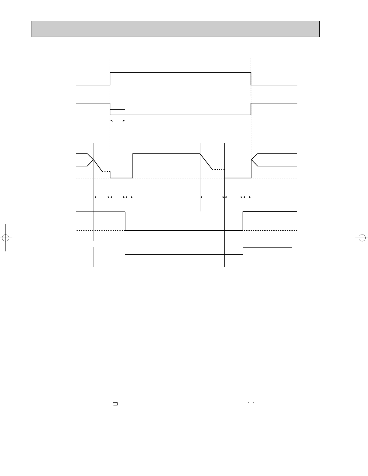
Time chart of defrosting in HEAT mode (reverse type)
set position
set speed
set position
set speed
Indoor fan
Compressor normal
Outdoor fan
R.V. coil
(21S4)
OFF (COOL)
OFF
Maximum frequency
horizontal
Horizontal vane
Very Low (temperature of indoor coil thermistor > 18:)
30
seconds
30
seconds
30
seconds
40
seconds
5 seconds 5 seconds
40
seconds
OFF
OFF
OFF
ON (HEAT)
ON ON
ON (HEAT)
<indoor unit>
<outdoor unit>
5-4. AUTO CHANGE OVER ··· AUTO MODE OPERATION
1. Mode selection
Once desired temperature is set, unit operation is switched automatically between COOL and HEAT operation.
(1) Initial mode
At first indoor unit operates only indoor fan with outdoor unit OFF for 3 minutes to detect present room temperature.
Following the conditions below, operation mode is selected.
1 If the room temperature thermistor RT11 reads more than set temperature, COOL mode is selected.
2 If the room temperature thermistor RT11 reads set temperature or less, HEAT mode is selected.
(2) Mode change
In case of the following conditions the operation mode is changed.
1 COOL mode changes to HEAT mode when 15 minutes have passed with the room temperature 2 degrees below the
set temperature.
2 HEAT mode changes to COOL mode when 15 minutes have passed with the room temperature 2 degrees above the
set temperature.
In the other cases than the above conditions, the present operation mode is continued.
NOTE1: Mode selection is performed when multi standby (refer to NOTE2) is released and the unit starts operation with
ON-timer.
NOTE2: If two or more indoor units are operating in multi system, there might be a case that the indoor unit, which is
operating in AUTO ( ), cannot change over the other operating mode (COOL HEAT) and becomes a
state of standby.
(3) Indoor fan control/ Vane control
As the indoor fan speed and the horizontal vane position depend on the selected operation mode, when the operation
mode changes over, they change to the exclusive ones.
58

5-5. INDOOR FAN MOTOR CONTROL
COOL
Fan speed
Up
Down
Up
Down
Mode
HEAT
Compressor frequency
MUZ-FA25 MUZ-FA35
<Relation between compressor frequency and fan speed>
43Hz
33Hz
43Hz
33Hz
54Hz
41Hz
54Hz
41Hz
Up
Down
Fan speed
High
Low
Compressor frequency
Min.
Max.
(1) Rotational frequency feedback control
The indoor fan motor is equipped with a rotational frequency sensor, and outputs signal to the microprocessor to feedback
the rotational frequency. Comparing the current rotational frequency with the target rotational frequency (Super High, High,
Med., Low), the microprocessor adjusts fan motor electric current to make the current rotational frequency close to the
target rotational frequency. With this control, when the fan speed is switched, the rotational frequency changes smoothly.
Rotational frequency
Super High
High
Med.
Low
Super High
(2) Fan motor lock-up protection
time
When the rotational frequency feedback signal has not output for 12 seconds, (or when the microprocessor cannot
detect the signal for 12 seconds) energizing to the fan motor is stopped. Then the microprocessor retries detection 3
times every 30 seconds. If the microprocessor still cannot detect the signal, the fan motor is regarded locked-up. When
the fan motor lock-up, POWER lamp flashes on and off to show the fan motor abnormality.
5-6. OUTDOOR FAN MOTOR CONTROL
Fan speed is switched according to the compressor frequency.
5-7. AUTO VANE OPERATION
1. Horizontal vane
(1) Vane motor drive
These models are equipped with a stepping motor for the horizontal vane. The rotating direction, speed, and angle of
the motor are controlled by pulse signals (approx. 12V) transmitted from indoor microprocessor.
(2) The horizontal vane angle and mode changes as follows by pressing VANE CONTROL button.
(3) Positioning
The vane is once pressed to the vane stopper to confirm the standard position and then moves to the set angle.
Confirming of standard position is performed in case of follows.
(a) When the operation starts or finishes (including timer operation).
(b) When the test run starts.
(c) When multi-standby starts or finishes.
59

(4) VANE AUTO ( ) mode
Horizontal
position
The air conditioner starts heating operation approx. 3 minutes
after the vane has moved to the
horizontal position.
• Sometimes the area
around your feet may not
warm. To warn the area
around the feet, set the
horizontal vane to
(AUTO) or the downwardblowing position.
• When VANE CONTROL
button is pressed again,
the vane returns to the
previously-set position
and the air conditioner
starts the heating operation
in approx. 3minutes.
To change the air
flow direction
When to use this function?
Use this function if you don’t
want the air from the indoor
unit to blow directly onto your
body.
• Depending on the shape of
the room,the air may blow
directly onto your body.
• Press VANE CONTROL
button again to return the
vane to the previously-set
position.
The air conditioner starts the
cooling or drying operation
approx. 3 minutes after the
vane has moved to the horizontal position.
•
Pressing and holding
VANE CONTROL
button for 2 seconds
or more causes
the horizontal vane
to reverse and
move to horizontal
position.
COOL/DRY
HEAT
NOTE:
• If you make the air flow not to blow directly onto your body by pressing VANE CONTROL button,
the compressor stops for 3 minutes even during the operation of the air conditioner.
• The air conditioner operates with decreased air flow until the compressor turns on again.
(9) To change the air flow direction not to blow directly onto your body.
Horizontal
position
When VANE CONTROL
button is pressed again,
the vane returns to the
previously-set position
and the air conditioner
starts the cooling or
drying operation in
approx. 3minutes.
The microprocessor automatically determines the vane angle and operation to make the optimum room temperature distribution.
COOL and DRY operation
Vane angle is fixed to Horizontal position.
HEAT operation
Vane angle is fixed to Angle 4.
(5) STOP (operation OFF) and ON-TIMER standby
When the following cases occur, the horizontal vane returns to the closed position.
(a) When OPERATE/STOP (ON/OFF) button is pressed (POWER OFF).
(b) When the operation is stopped by the emergency operation.
(c) When ON-TIMER is ON standby.
(6) Dew prevention
During COOL or DRY operation with the vane angle at Angle 2 ~ 4 when the compressor cumulative operation time
exceeds 1 hour, the vane angle automatically changes to Angle 1 for dew prevention.
(7) SWING MODE ( )
By selecting SWING mode with VANE CONTROLbutton, the horizontal vane swings vertically. The remote controller
displays “”. SWING mode is cancelled when VANE CONTROLbutton is pressed once again.
(8) Cold air prevention in HEAT operation.
When any of the following conditions occurs in HEAT operation, the vane angle changes to Horizontal position automatically to prevent cold air blowing on users.
① Compressor is not operating.
➁ Defrosting is performed.
➂ Indoor coil thermistor RT12 reads 24: or below.
➃ Indoor coil thermistor RT12 temperature is raising from 24°C or below, but it does not exceed 39:.
⑤ For about 3 minutes after compressor starts.
NOTE : When 2 or more indoor units are operated with multi outdoor unit, even if any indoor unit turns thermostat off,
this control doesn’t work in the indoor unit.
60

(
(SWING)
1
23
45
10
) ECONO COOL ( ) operation (ECONOmical operation)
When ECONO COOL button is pressed in COOL mode, set temperature is automatically set 2°C higher.
Also the horizontal vane swings in various cycle according to the temperature of indoor heat exchanger(RT12).
SWING operation makes you feel cooler than set temperature. So, even though the set temperature is higher, the air
conditioner can keep comfort. As a result, energy can be saved.
ECONO COOL operation is cancelled when ECONO COOL button is pressed once again or VANE CONTROL
button is pressed or change to other operation mode.
<SWING operation>
In swing operation of ECONO COOL operation mode, the initial air flow direction is adjusted to “Horizontal”.
According to the temperature of indoor coil thermistor RT12 at starting of this operation, next downward blow time is
decided. Then when the downward blow has been finished, next horizontal blow time is decided.
For initial 10 minutes the swing operation is performed in table G~H for quick cooling.
Also, after 10 minutes when the difference of set temperature and room temperature is more than 2:, the swing operation is performed in table D~H for more cooling.
The air conditioner repeats the swing operation in various cycle as follows.
Temperature of indoor
coil thermistor RT12
A
B
C
D
E
F
G
H
15°C or less
15°C to 17°C
17°C to 18°C
18°C to 20°C
20°C to 21°C
21°C to 22°C
22°C to 24°C
more than 24°C
Downward blow time
(second)
2
5
8
11
14
17
20
23
Horizontal blow time
(second)
23
20
17
14
11
8
5
2
2. Vertical vane
(1) Vane motor drive
These models are equipped with a stepping motor for the vertical vane. The rotating direction, speed, and angle of the
motor are controlled by pulse signals (approximate 12V) transmitted from microprocessor.
(2) The vertical vane angle and mode change as follows by pressing WIDE VANE button.
(3) Positioning
The vane presses the vane stopper once to confirm the standard position and then set to the desired angle.
Confirming of standard position is performed in case of follows.
(a) When OPERATE/STOP(ON/OFF) button is pressed (POWER ON).
(b) When SWING is started.
(4) SWING MODE ( )
By selecting SWING mode with WIDE VANE button, the vertical vane swings horizontally. The remote controller displays
“”. Swing mode is cancelled when WIDE MODE button is pressed once again.
5-8. i-see CONTROL OPERATION
The sensors constantly measure the room and floor/wall temperatures to automatically adjust to the set temperature
by estimating the temperature actually perceived by a person inside the room (“sensory temperature”).
Advantages
· The air inside the room is conditioned quickly to a comfortable condition.
· The room will not become too cold or hot even when the air conditioner is kept on for a long period.
· The air conditioner will not overcool or overheat, which means you can save on electricity.
i-see control operation is activated when i-see button is pressed with a thin stick in manual COOL or manual HEAT mode.
NOTE :
i-see control operation is activated when the remote controller is first used following replacement of the batteries or
resetting of the remote controller.
i-see control operation is cancelled when i-see button is pressed with a thin stick once again.
NOTE :
If the conditioner is turned OFF without cancelling i-see control operation, i-see control operation is activated the next
time the air conditioner is turned ON.
61

i-see Sensor
(1) Press OPERATE / STOP (ON/ OFF)button to start the air conditioner.
(2) Press i-see button. (NOTE 1)
(3) Press AREA button.
Each time the button is pressed, the area is changed in sequence:
NOTE1: AREA setting is only available during i-see control operation.
NOTE2: If AREA setting is canceled, the vertical vane returns to the previously set position before AREA setting.
NOTE3: The horizontal air flow direction (WIDE VANE button), including horizontal SWING, cannot be set during AREA setting.
(AUTO) (LEFT) (RIGHT) Cancel
The indoor unit delivers warm air detecting the cold area in the room.
· If AREA setting is set to AUTO in heating operation, the indoor unit automatically delivers warm air to the area
where the floor/wall temperature is the lowest in the room.
· If AREA setting is set to AUTO in cooling operation, the indoor unit automatically delivers cool air to the area
where the floor/wall temperature is the highest in the room.
Ex.) In heating operation
Moving of horiz
ontal air flow direction
Indoor unit
display
NOTE
· The horizontal air flow direction changes if i-see Sensor detects approx. 3; temperature difference.
· In AUTO of AREA setting, both right and left lamps are lighted when the room is evenly air-conditioned.
Indication of AREA setting
Day
Night
Warm area Cold area
Lighted
Not lighted
i-see Sensor moves intermittently, measuring the floor and wall temperature.
i-see Sensor, which is installed on the right side of the air outlet of the indoor unit, is moved with the stepping motor and it
detects the floor/ wall temperature.
i-see Sensor is installed here.
Enlarged view of i-see Sensor
i-see Sensor
When AREA setting is not activated, the sensing range of i-see Sensor differs depending on the installation
·
location of the air conditioner.
Installation
position
Image of sensing
range
Direction of sensor
Refer to the description on service manual OB371 (8-4. Remote controller) for slide switch settinng.
Installed at left Installed at center Installed at right
Right Center Left
· Install the front panel correctly after being removed for maintenance or service so that the
floor/wall temperatures can be measured correctly.
5-9. AREA ( ) SETTING
62

(4) AREA setting is cancelled when the "cancel" is sellected by pressing AREA button, or when WIDE VANE
button is pressed.
Indoor unit installation location and air-conditioning area
Installed at left Installed at center Installed at right
LEFT RIGHT LEFT RIGHT LEFT RIGHT
· Be sure to set the slide switch inside the remote controller to an appropriate position in accordance with the installed
position of the indoor unit. If the switch is not set correctly, the air conditioner may not function properly.
(Refer to Service manual OB371 8-4.)
To air-condition mainly
the left area of the room
AREA
Press AREA button
to select LEFT.
Remote controller button
Remote controller display
i-see Sensor operation
Control range
of horizontal air
flow direction.
The vertical air
flow direction
conforms to the
setting on the
remote controller.
(The horizontal
air flow direction
is controlled in
this range.)
Indoor unit
display
NOTE: If the AREA setting is activated (AUTO), i-see Sensor moves in a range of 150 degrees detecting
floor/wall temperature of 3 area (left, right, center). Therefore, the detected temperatures
may be different from the temperatures measured on commercial thermometers
depending on the condition or temperature distribution on the floor and/or wall.
Installed
at center
Installed
at left
Installed
at right
To air-condition the entire room
The horizontal air flow direction and indoor unit display are switched according to the room temperature (floor/wall).
Press AREA button to select AUTO.
or
or
Operation and operating range
i-see sensor moves 30 degrees from the center in both right and left side.
To air-condition mainly
the right area of the room
Press AREA button
to select RIGHT.
Approx. 150 degrees
i-see Sensor turning to the left
i-see Sensor operates as follows in accordance with AREAsetting made with the remote controller.
“AUTO” in AREAsetting; first turning to the LEFT for adjusting the position then.....
CENTER RIGHT CENTER LEFT CENTER......
(The sensor turns to the right, left and center.)
“RIGHT” in AREAsetting; first turning to the LEFT for adjusting the position then....
CENTER RIGHT CENTER RIGHT CENTER......
(The sensor turns to the right and center.)
“LEFT” in AREAsetting; first turning to the LEFT for adjusting the position then....
CENTER LEFT CENTER LEFT CENTER......
(The sensor turns to the left and center.)
The sensor finishes turning to one area to another for 3 seconds and it operates one area for 5 seconds.
i-see Sensor turning to the center
63
i-see Sensor turning to the right

PLASMA/WASH lamp
Blinking
Not lighted
Lighted
WASH reset switch
WASH
reset
E.O.
SW
Each time this b utton is pressed, the oper ation mode of PLASMA is changed in
sequence:
Cancel (The sign of PLASMA oper ation disappears .)
PLASMA/WASH lamp tur ns on in the displa y section of the indoor unit and
PLASMA DEODORIZING and/or PLASMA AIR PURIFYING unit is energyz ed.
Adjust the air flow to your desired speed.
(1) Press OPERATE/STOP (ON/OFF) button to start the air conditioner.
(2) Press PLASMA button to set PLASMA DUO operation.
(3) PLASMA operation is cancelled when the "cancel" is selected by pressing PLASMA button.
Once PLASMA operation is selected, PLASMA operation will be performed every time
the air conditioner is turned on until the "Cancel" is selected with PLASMA button.
5-10. PLASMA DUO ( ) OPERATION
● Never touch the PLASMA DEODORIZING/AIR PURIFYING filter units during the operation of the air
conditioner. Although the filter units are safety-conscious design, touching the units could be the cause
of trouble as they discharge high voltage electricity.
PLASMA/WASH lamp
Not lighted
Lighted
Description of PLASMA DUO operation:
< function>
Both PLASMA DEODORIZING and PLASMA AIR PURIFYING operation work.
<
function>
PLASMA DEODORIZING operation cleans the air inside the room by adsorbing and decomposing
the particles of odor-releasing substances and gases such as formaldehyde.
<
function>
PLASMA AIR PURIFYING operation cleans the air inside the room by absorbing the particles of cigarette
smoke or allergens such as pollens and house dust.
NOTE1: Carbon monoxide released from cigarettes cannot be removed by PLASMA operation.
Open the windows to let the outside air in from time to time.
NOTE2: During PLASMA operation, you may smell ozone that is generated in small quantities
from PLASMA DEODORIZING/AIR PURIFYING filter units. This is not a malfunction.
NOTE3: You may hear a small "hissing" sound during PLASMA operation. This is the sound of plasma
discharge, and not a malfunction.
<Cleaning>
When PLASMA/WASH lamp is blinking, please clean PLASMA DEODORIZING/AIR PURIFYING filter units.
After cleaning of PLASMA DEODORIZING/AIR PURIFYING filter units, press WASH reset switch.
A short “beep” is heard and the blinks of PLASMA/WASH lamp will be cancelled.
64

START
STOP
START
STOP
5-11. AUTO FRONT PANEL
When the unit starts operating, the front panel opens automatically to draw in air.
When the unit stops operating, the front panel closes automatically.
Open
Closed
Operation and operating range of the auto front panel
The front panel fully opens 10 mm or more upper than the level line of the top end of the nozzle assembly.
It takes about 13 seconds to open the front panel completely.
10 mm or more
Z-Z Side view
5-12. TIMER OPERATION
1. How to set the timer
(1) Press OPERATE/STOP (ON/OFF) button to start the air conditioner.
(2) Check that the current time is set correctly.
NOTE : Timer operation will not work without setting the current time. Initially “AM0:00” blinks at the current time display of
TIME MONITOR, so set the current time correctly with CLOCK SET button.
ON timer setting
(1) Press ON-TIMER button( ) to set ON timer.
Each time the button is pressed, ON timer mode alternates between ON and OFF.
(2) Set the time of the timer using TIME SET buttons ( and ).
Each time FORWARD button( ) is pressed, the set time increases by 10 minutes; each time BACKWARD
button ( ) is pressed, the set time decreases by 10 minutes.
OFF timer setting
(1) Press OFF-TIMER button ( ) to set OFF timer.
Each time the button is pressed, OFF timer mode alternates between ON and OFF.
(2) Set the time of the timer using TIME SET buttons ( and ).
Each time FORWARD button ( ) is pressed, the set time increases by 10 minutes; each time BACKWARD ( )
button is pressed, the set time decreases by 10 minutes.
2. Cancel
TIMER setting can be cancelled with ON/OFF TIMER buttons.
To cancel ON timer, press ON-TIMER button ( ).
To cancel OFF timer, press OFF-TIMER button( ).
TIMER is cancelled and the display of set time disappears.
65

EMERGENCY OPERATION switch
WASH
reset
E.O.
SW
Operation mode COOL HEAT
Set temperature
24:
24:
Fan speed Medium Medium
Horizontal vane Auto Auto
Vertical vane Straight Straight
The operation mode is indicated by the Operation Indicator lamp on the indoor unit as following figure.
Operation Indicator lamp
NOTE:
This is the indication of EMERGENCY OPERATION
mode. AREA setting is not available during EMERGENCY OPERATION.
Press again <Heat>
Press once <Cool>
Lighted
Not lighted
Press once again <Stop>
PROGRAM TIMER
• The OFF timer and ON timer can be used in combination. The timer of the set time that is reached first will operate first.
• “” and “” display shows the order of the OFF timer and the ON timer operation.
(Example 1) The current time is 8:00 PM.
The unit turns off at 11:00 PM, and on at 6:00 AM.
(Example 2) The current time is 11:00 AM.
The unit turns on at 5:00 PM, and off at 9:00 PM.
NOTE : If the main power is turned off or a power failure occurs while AUTO START/STOP timer is active, the timer setting is
cancelled. As these models are equipped with an auto restart function, the air conditioner starts operating with timer
cancelled when power is restored.
5-13. EMERGENCY / TEST OPERATION
In case of test run operation or emergency operation, use EMERGENCY OPERATION switch on the front of the indoor
unit. Emergency operation is available when the remote controller is missing, has failed or the batteries of the remote
controller run down. The unit will start and AREAlamp will light.
The first 30 minutes of operation is the test run operation. This operation is for servicing. The Indoor fan speed runs at
High speed and the system is in continuous operation (The thermostat in ON).
After 30 minutes of test run operation, the system shifts to EMERGENCY COOL / HEAT MODE with a set temperature of
24°C. The fan speed shifts to Med..
The coil frost prevention works even in emergency operation, and defrosting too.
In the test run or emergency operation, the horizontal vane operates in VANE AUTO ( ) mode.
Emergency operation continues until EMERGENCY OPERATION switch is pressed once or twice or the unit receives any
signal from the remote controller. In case of latter, normal operation will start.
NOTE1 : Do not press EMERGENCY OPERATION switch during normal operation.
NOTE2 : 3 seconds after EMERGENCY OPERATION switch is pressed, the front panel starts moving forward
automatically.
66

5-14. INVERTER SYSTEM CONTROL
POWER P.C. BOARD
Power
supply
INVERTER P.C. BOARD
R64A R64B
CT
TR821
DB65
X64
L62 L63
C63A
C63B
C63C
DB61
L61
P
W
V
U
N
CT761
CT781
IPM
U
W
MC
V
+
Booster chopper circucuit
SYMBOL
IPM
C63A/C63B/C63C
CT761/CT781
CT
DB61
R64A, R64B
X64
DB65
TR821
L61
NAME
INTELLIGENT POWER MODULE
SMOOTHING CAPACITOR
CURRENT TRANSFORMER
CURRENT TRANSFORMER
DIODE MODULE
CURRENT-LIMITING RESISTOR
RELAY
DIODE MODULE
SWITCHING POWER TRANSISTOR
REACTOR
FUNCTION
It supplies three-phase AC power to compressor.
It stabilizes the DC voltage.
It measures the current of the compressor motor.
It measures the value of current which is supplied to the main power
supply circuit.
It converts the AC voltage to DC voltage.
It absorbs the rush current not to run into the main power supply circuit
when the electricity turns ON.
It short-circuits the resistance which restricts rush current during the
normal operation after the compressor startup.
Booster
chopper
circuit
Function of main parts
It improves power factor.
It rectifies AC and controls its voltage.
5-14-2. Outline of main power supply circuit
1. At the start of operation
Main power supply circuit is formed when X64 (Relay) is turned ON at compressor startup.
To prevent rush current from running into the circuit when power supply is turned ON,
R64A and R64B (Current-limitting resistor) are placed in sub circuit.
2. At normal operation
1 When AC runs into POWER P.C. board, its external noise is eliminated in the noise filter circuit.
2 After noise is eliminated from AC, it is rectified to DC by DB61 (Diode module).
3 DC voltage, to which AC has been rectified by process 2, is stabilized by C63A, C63B and C63C (Smoothing capacitor)
and supplied to IPM (Intelligent power module).
4 DC voltage, which has been stabilized in process 3, is converted to three-phase AC by IPM and supplied to
compressor.
5 CT761 and CT781 (Current Transformer), which are placed in the power supply circuit to compressor, are used to
measure the value of phase current and locate the polar direction of rotor with algorithm. PWM (Pulse width modulation)
controls impressed voltage and frequency with those information.
5-14-1. Inverter main power supply circuit
67

4. Intelligent power module
IPM consists of the following components
· IGBT (x6) : Converts DC waveform to three-phase AC waveform and outputs it.
· Drive Circuit : Drives transistors.
· Protection circuit : Protects transistors from overcurrent.
Since the above components are all integrated in IPM, IPM has a merit to make the control circuit simplify and miniaturize.
5. Smoothing capacitor
C63A, C63B and C63C stabilize the DC voltage and supply it to IPM.
6. Elimination of electrical noice
Noise filter circuit, which is formed by *CMC COILS capacitors placed on the POWER P.C. board, eliminates electrical
noise of AC power that is supplied to main power supply circuit. And this circuit prevents the electrical noise generated in
the inverter circuit from leaking out.
*CMC COILS; Common mode choke coils
Outline of simple partial switching method
In conventional inverter models, diode module rectifies AC voltage to DC voltage, smoothing capacitor makes its DC waveform
smooth, and IPM converts its DC voltage to imitated AC voltage again in order to drive the compressor motor.
However, it has been difficult to meet IEC harmonic current emission standard by above circuit because harmonic gets
generated in the input current waveform and power factor gets down. The simple partial switching method with PAM, which has
been adopted this time, places and utilizes the booster chopper circuit (L61, DB65 and TR821) before rectifying AC voltage in
the general passive-method converter circuit. As harmonic gets suppressed and the peak of waveform gets lower by adding
booster chopper circuit as mentioned above and by synchronizing the timing of one-time switching with the zero-cross point of
waveform, the input current waveform can be improved and the requirement of IEC harmonic current emission standard can be
satisfied. Since the switching times is just once by synchronizing with the zero cross point, this simple partial switching method
has the feature of lower energy loss compared to active filter method. In addition, output and efficiency is enhanced by
combining with vector-controlled inverter in order to boost the voltage of power supplied to IPM.
Input current waveform without PAM Input current waveform with PAM
Due to the time of no electricity;
· Power factor gets worse.
· Harmonic gets increased.
Input voltage
Release of energy stored in L
Energized time is
extended by optimization
of L inductance.
Peak gets down.
Energized time is short in
case L inductance is small.
No electricity runs into
diode module because the
voltage at both sides of smoothing
capacitor is higher than input voltage.
Compulsory energizing
by switching.
Input current
Owing to the increase of energized time;
· Power factor gets better.
· Harmonic gets suppressed.
3. Purpose of PAM adoption
PAM : Pulse Amplitude Modulation
PAM has been adopted for the efficiency improvement and the adaptation to IEC harmonic current emission standard.
Sine wave control
In these air conditioners, compressor equips brushless DC motor which doesn't have Hall element.
In short, the motor is sensorless. However, it's necessary to locate the polar direction of rotor in order to drive brushless DC
motor efficiently. The general detection method of the polar direction for such a DC motor is to locate it from the voltage induced
by unenergized stator.
Therefore, It is necessary to have a certain period of time in which the stator is being unenergized for the rotor position
detection when the voltage of supplied power is impressed.
So the motor has been driven by square wave control (the conventional motor drive system) which energizes the motor only
when the range of electrical angle is within 120_ because it is forced to be unenergized within 30_ at start & end of one heap
in one waveform cycle (180_) when the voltage is impressed.
However, torque pulsation occurs at rotation in this method when the current-carrying phases are switched over to other
phases in sequence. Therefore, sine wave control system is adopted for these air conditioners because it can make the
phase-to-phase current waveform smoother (sine wave) in order to drive the motor more efficiently and smoothly.
68

1 hour
Time
Maximum
frequency
Upper limit
frequency
Rated frequency or less
5-15. OPERATIONAL FREQUENCY CONTROL OF OUTDOOR UNIT
Rotor
Rotor Position Signal
Permanent magnet is embedded.
Necessary
DC Motor
Excited by magnetic field of stator
Unnecessary
AC Motor
5-14-3. Characteristics of sine wave control in case of brushless DC motor
● Although ordinary three-phase induction motor requires energy to excite the magnetic field of rotor, brushless DC motor
doesn't need it. So, higher efficiency and torque are provided.
● This control provides the most efficient waveform corresponding to the rotation times of compressor motor.
● The rotation can be set to higher compared to the conventional motor drive system. So, the time in which air conditioner
can be operated with energy saved is longer than conventional models. This can save annual electric consumption.
● Compared to square wave control, the torque pulsation is reduced at rotation so that the motor operates more quietly.
● Since response and efficiency of motor are enhanced in sine wave control, finer adjustment can be provided.
w In brushless DC motor, permanent magnet is embedded in the rotor. Therefore, it doesn't require energy to excite the rotor
like AC motor does. However, it's necessary to control the frequency of three-phase AC current supplied to the stator
according to the polar direction of magnet embedded in the rotor so as to drive the motor efficiently. Controlling three-phase
AC current frequency also means controlling the timing to switch the polarity of stator. Therefore, the polar direction of rotor
needs to be detected.
5-14-4. Control Method of Rotation Times
Sine wave control makes the current transformers conduct real time detection of the value of the current running into the motor,
locates the rotor position from the detected value, and decides if voltage should be impressed and if frequency should be chan ged.
Compared to the conventional control and rotor position detection method, sine wave control can provide finer adjustment of the
voltage of supplied power. The value of the current running into the motor is determined by each motor characteristic.
1. Outline
The operational frequency is as following:
First, the target operational frequency is set based on the difference between the room temperature and the set temperature.
Second, the target operational frequency is regulated by discharge temperature protection, high pressure protection,
electric current protection and overload protection and also by the maximum/minimum frequency.
2. Maximum/minimum frequency in each operation mode
COOL
Applied
model
MUZ-FA25VA
MUZ-FA25VAH
MUZ-FA35VA
MUZ-FA35VAH
w The operation frequency in COOL mode is restricted the upper limit frequency after 1 hour as shown below for
dew prevention.
It is rated frequency or less.
Minimum
frequency
28
28 70
Rated
frequency
57
Maximum
frequency
98
86
Minimum
frequency
45
35
HEAT
Rated
frequency
77 105
73 98 28
Maximum
frequency
Minimum
frequency
28
69
DRY
Maximum
frequency
58
57
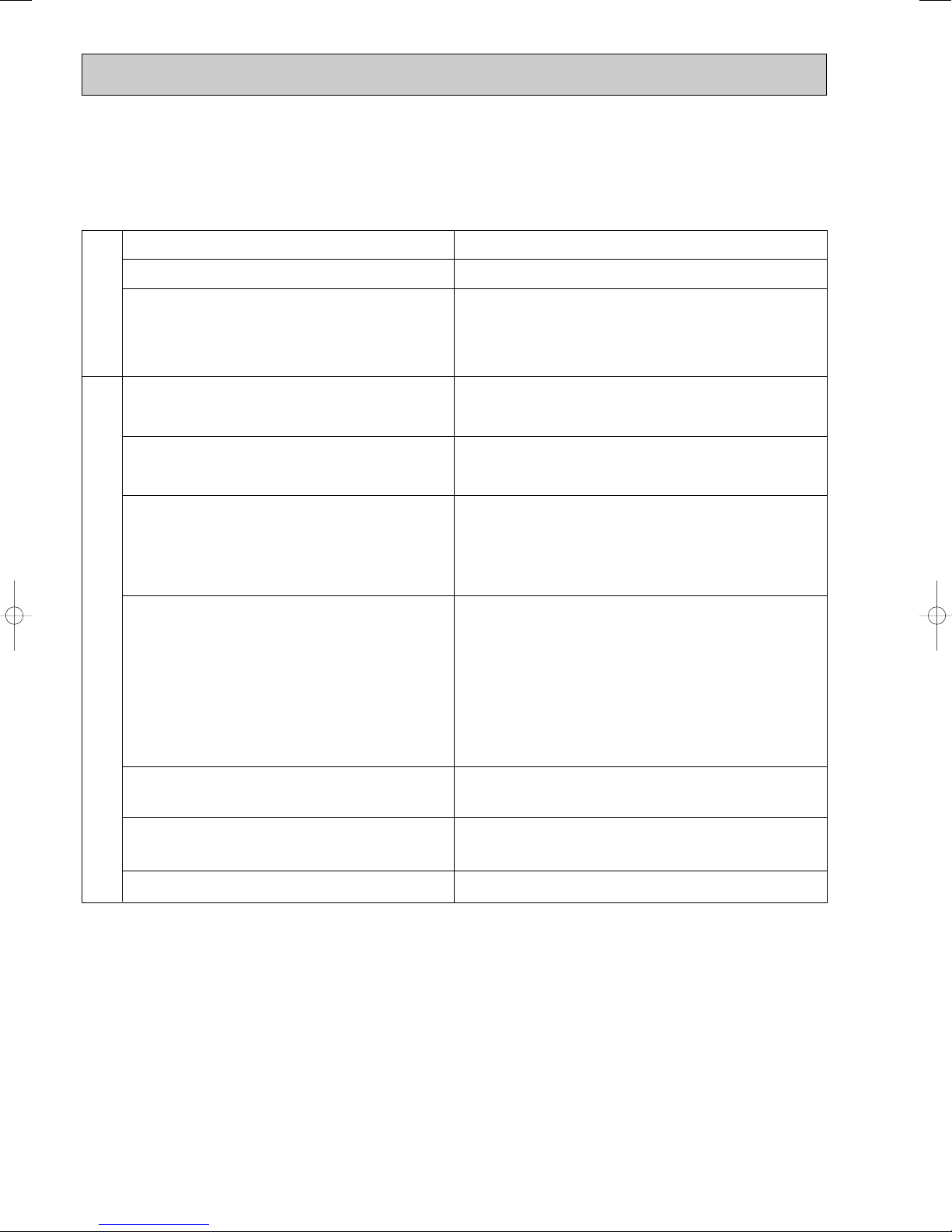
5-16. EXPANSION VALVE CONTROL (LEV CONTROL)
(1) Outline of LEV control
The LEV basic control is comprised of setting LEV opening degree to the standard opening degrees set for each opera-
tional frequency of the compressor. However, when any change in indoor/outdoor temperatures or other factors cause
air conditioning load fluctuation, the LEV control also works to correct LEV opening degree based on discharge temperature (Shell temperature) of the compressor, developing the unit’s performance.
Control range from minimum 33 pulse to maximum 500 pulse.
Actuating speed LEV opens 40 pulse/second and close 90 pulse/second
Opening degree adjustment LEV opening degree is always adjusted in opening direction.
standard
specification
Unit OFF LEV remains at maximum opening degree (reaches maxi-
Remote controller ON LEV is positioned. (first full-closed at zero pulse and then
(When reducing the opening degree, LEV is once overclosed, and then adjusted to the proper degree by opening.
mum opening degree approximate in 15 minutes after compressor stops)
positioned.)
COOL · DRY MODE
During 1 to 5 minutes after compressor starts
HEAT MODE
During 1 to 15 minutes after compressor starts
More than COOL, DRY: 5/ HEAT: 15 minutes have
passed since compressor start-up
general operation
Thermostat OFF LEV is adjusted to exclusive opening degree for thermostat
Thermostat ON
Defrosting in HEAT mode LEV is adjusted to open 500 pulse.
LEV is fixed to standard opening degree according to operational frequency of compressor.
LEV opening degree is corrected to get target discharge
temperature of compressor.
(For discharge temperature lower than target temperature,
LEV is corrected in closing direction.)
(For discharge temperature higher than target temperature,
LEV is corrected in opening direction.)
wIt may take more than 30 minutes to reach target temperature, depending on operating conditions.
OFF.
LEV is controlled in the same way as that after the compressor has started up.
70

(2) Time chart
OFF Time
Time
ON
Operational frequency
of the compressor
Commanded
to open
Standard
opening
degree
Opening degree is
corrected according
to discharge
temperature.
Positioning
Air conditioner ON
Air conditioner OFF
(thermostat off)
LEV opening degree
about 5 minutes <COOL, DRY>
about 15 minutes <HEAT>
06
05
04
03
02
01
LEV opening degree
A(target discharge temperature)
B
C
D
E
F
30 50 70
Operational frequency of the compressor
90 110 130
(Hz)
(3) Control data
(a) Reference value of target discharge temperature
(COOL/HEAT :)
A
MUZ-FA25VA
MUZ-FA25VAH
MUZ-FA35VA
MUZ-FA35VAH
In COOL operation, the two indoor coil thermistors (one main and one sub) sense temperature ununiformity (super
heat) at the heat exchanger, and when temperature difference have developed, the indoor coil thermistors adjust
LEV opening degree to get approximate 10 degrees lower temperature than the target temperature in the table
above, thus diminishing super heat.
47/41B53/48C58/55
50/45
53/52 60/59
(b) Reference value of LEV standard opening degree
(COOL/ HEAT pulse)
MUZ-FA25VA
MUZ-FA25VAH
MUZ-FA35VA
MUZ-FA35VAH
01
150/110
130/100
02
190/11003240/15004280/17005310/20006340/230
190/130 240/170
D
63/60
66/68
260/210
E
67/65F67/65
70/76 70/76
260/230
260/230
71

6
Approx.
2 :
or more
Difference
between target
temperature
and room
temperature
Approx.
2 :
or less
This shows that the
air conditioner is
operating to reach
the target temperature.
Please wait until the
target temperature is
obtained.
This shows that the
room temperature is
approaching the
target temperature.
Operation state
Indication
Lighted
Not lighted
•The following indication applies regardless of shape of the indicator.
Operation Indicator
MSZ-GA • MSZ-CB MICROPROCESSOR CONTROL
MSZ-GA22VA MSZ-CB22VA
MSZ-GA25VA MSZ-CB25VA MUZ-GA25VA MUZ-GA25VAH
MSZ-GA35VA MSZ-CB35VA MUZ-GA35VA MUZ-GA35VAH
WIRELESS REMOTE CONTROLLER
Signal transmitting section
Operation display section
OPERATE/STOP
(ON/OFF) button
Temperature buttons
Indication of
remote controller
model is on back
(This diagram shows an overall view.)
FAN SPEED CONTROL button
OPERATION SELECT button
ECONO COOL button
RESET button
Once the operation mode is set, the same operation mode can be repeated by simply turning OPERATE/STOP
(ON/OFF) button ON.
Indoor unit receives the signal with a beep tone.
When the system turns off, 3-minute time delay will operate to protect system from overload and compressor will not
restart for 3 minutes.
INDOOR UNIT DISPLAY SECTION
Operation Indicator lamp
The operation indicator at the right side of the indoor unit indicates the operation state.
OFF-TIMER button
ON-TIMER button
TIME SET buttons
FORWARD button
BACKWARD button
CLOCK SET button
VANE CONTROL button
72

6-1. COOL ( ) OPERATION
(1) Press OPERATE/STOP(ON/OFF) button.
OPERATION INDICATOR lamp of the indoor unit turns on with a beep tone.
(2) Select COOL mode with OPERATION SELECT button.
(3) Press TEMPERATURE buttons (TOO WARM or TOO COOL button)to select the desired temperature.
The setting range is 16 ~ 31°C
1. Thermostat control
Thermostat is ON or OFF by difference between room temperature and set temperature
Initial temperature difference Thermostat
Room temperature minus set temperature : -1.0 : or more··············································ON
Room temperature minus set temperature : less than -1.0 :············································OFF
2. Indoor fan speed control
Indoor fan operates continuously at the set speed by FAN SPEED CONTROL button
regardless of the thermostat’s OFF-ON.
In AUTO the fan speed is as follows.
Initial temperature difference
Fan speed
Room temperature minus set temperature : 1.7 : or more ········································High
Room temperature minus set temperature : Between 1 and 1.7 :
··································
Med.
Room temperature minus set temperature : less than 1 : ········································Low
3. Coil frost prevention
Temperature control
When indoor coil thermistor detects following temperature for 90 seconds, operational frequency
of compressor is controlled according to the following table.
Temperature of indoor coil thermistor
10°C or more
Operation frequency
Normal (variable)
8°C to 10°C Raise 6Hz
6°C to 8°C
3°C to 6°C
Fixed
Lower 3Hz
Lower 6Hz
3°C or less
Compressor is turned OFF for 5 minutes when temperature of
indoor coil thermistor continues 3°C or less for 5 minutes or more.
The indoor fan maintains the actual speed of the moment.
4. Low outside temperature operation
MUZ-GA25
When the ambient temperature thermistor RT65 reads 17: or less, the operation mode moves to cool operation in low outside temperature from normal cool operation.
Each outdoor actuator (compressor/ fan/ solenoid valve) is operated in the exclusive control, which is different from one of
normal cool operation.
Especially fan motor doesn’t operates continuously to maintain sufficient cooling capacity.
(1) Outdoor fan control
Outdoor unit (compressor) operates with outdoor fan OFF basically.
But any of following conditions is satisfied, the outdoor fan turns ON for about 5 seconds.
a). the defrost thermistor RT61 reads 50: or more.
b). the fin temperature thermistor RT64 reads 60: or more.
(2) Solenoid valve control
In low outside temperature operation solenoid valve coil is energized and solenoid valve is open.
(3) Dew drop prevention
When the ambient temperature thermistor RT65 reads -12: or less, as coil frost or dew drop from indoor unit may
occur, the compressor turns OFF with the outdoor fan ON for prevention of them.
NOTE: This control can be released by cut of the jumper line JG on the outdoor inverter P.C. board.
Be sure to cut it since user accepts that maker can’t be responsible for coil frost or dew drop from indoor unit.
(4) Outside temperature detecting control
In this mode to detect the exact outside temperature the compressor turns OFF with the outdoor fan ON for 3 minutes
once 1 hour.
MUZ-GA35
If the outside temperature falls to 18°C or less during operation in COOL mode, the unit enters the low outside temperature
operation mode.
<Operation>
(1) If the unit enters the low outside temperature operation mode, the outside fan rotation speed gets slow down.
(2) Even when the unit is in the "thermostat-off" status under the low outside temperature operation mode, the outside fan
rotation does not stop.
(3) In this mode to detect the exact outside temperature the compressor turns OFF with the outdoor fan ON for 3 minutes
once 1 hour; if the outside temperature rises over 18°C, the unit goes back to the normal COOL mode, and if the
outside temperature is still 18°C or less, the unit stays in the low outside temperature operation mode.
(4) Dew drop prevention
When the ambient temperature thermistor RT65 reads -12: or less, as coil frost or dew drop from indoor unit may
occur, the compressor turns OFF with the outdoor fan ON for prevention of them.
WOther protections work as well as in the normal COOL mode.
Difference between room
temperature and set temperature during operation.
Set temperature
-0.7 :
-1.0 :
Difference between room
temperature and set temperature during operation
3 :
1.7 :
1 :
73

6-2. DRY ( ) OPERATION
35
30
25
20
15
10
:
10 15 20 25 30 35
Set temperature
Initial room temperature
Set temperature and
initial room temperature in dry mode
:
(1) Press OPERATE/STOP(ON/OFF) button.
OPERATION INDICATOR lamp of the indoor unit turns on with a
beep tone.
(2) Select DRY mode with OPERATION SELECT button.
(3) The microprocessor reads the room temperature and determines
the set temperature. Set temperature is as shown on the right
chart.
The system for dry operation uses the same refrigerant circuit as the cooling circuit.
The compressor and the indoor fan are controlled by the room temperature.
By such controls, indoor flow amounts will be reduced in order to lower humidity without much room temperature decrease.
1. Thermostat control
Thermostat is ON or OFF by difference between room temperature and set temperature.
Room temperature minus set temperature : -1.0 : or more··············································ON
Room temperature minus set temperature : less than -1.0 :············································OFF
2. Indoor fan speed control
Indoor fan operates at the set speed by FAN SPEED CONTROL button.
When thermostat OFF (compressor OFF) fan speed becomes Very Low.
In AUTO the fan speed is as follows.
Room temperature minus set temperature : 1.7 : or more ········································High
Room temperature minus set temperature : Between 1 and 1.7 :
Room temperature minus set temperature : less than 1 : ········································Low
3. Coil frost prevention
Coil frost prevention is as same as COOL mode. (6-1.3.)
The indoor fan maintains the actual speed of the moment.
4. Low outside temperature operation
Low outside temperature operation is as same as COOL mode. (6-1.4.)
6-3. HEAT ( ) OPERATION
(1) Press OPERATE/STOP(ON/OFF) button.
OPERATION INDICATOR lamp of the indoor unit turns on with a beep tone.
(2) Select HEAT mode with OPERATION SELECT button.
(3) Press TEMPERATURE buttons (TOO WARM or TOO COOL button) to select the desired temperature.
The setting range is 16 ~ 31°C.
1. Thermostat control
Thermostat is ON or OFF by difference between room temperature and set temperature.
Room temperature minus set temperature : less than 2.0 :··············································ON
Room temperature minus set temperature : 2.0 : or more················································OFF
2. Indoor fan speed control
(1) Indoor fan operates at the set speed by FAN SPEED CONTROL button.
In Auto the fan speed is as follows.
Set temperature minus room temperature: 2 :or more
Set temperature minus room temperature:
Set temperature minus room temperature: less than 0.2
(2) Cold air prevention control
1 When the compressor is not operating,
(1) if the temperature of room temperature thermistor RT11 is less than 19°C, the fan stops.
(2) if the temperature of room temperature thermistor RT11 is 19°C or more and
(1) if the temperature of RT12 is less than 0°C, the fan stops.
(2) if the temperature of RT12 is 0°C or more, the fan operates at Very Low.
2 When the compressor is operating,
(1) if the temperature of RT12 is 40°C or more, the fan operates at set speed.
(2) if the temperature of RT12 is less than 40°C and
(1) if heating operation starts after defrosting, the fan stops.
(2) if the temperature of room temperature thermistor RT11 is 19°C or less, the fan stops.
(3) if the temperature of room temperature thermistor RT11 is more than 19°C, the fan operates at Very Low.
NOTE : When 3 minutes have passed since the compressor started operation, this control is released regardless of the
temperature of RT11 and RT12.
Initial temperature difference Thermostat
Initial temperature difference
··································
Fan speed
Med.
Initial temperature difference Thermostat
Initial temperature difference
Fan speed
·················································· High
Between 0.2 and 2 : ·································
:··············································
Med.
Low
74
Difference between room
temperature and set temperature during operation
Set temperature
-1.0 :
-0.7 :
Difference between room
temperature and set temperature during operation
2.5 :
1.7 :
1 :
Difference between room
temperature and set temperature during operation
Set temperature
2.0 :
1.7 :
Difference between room
temperature and set temperature during operation
2 :
4 :
0.2 :
1.7 :

3. High pressure protection
5: 8:
Defrost heater
ON
OFF
In HEAT operation the indoor coil thermistor detects the temperature of the indoor heat exchanger. The compressor operational frequency is controlled to prevent the condensing pressure from increasing excessively.
4. Overload starting
When the room temperature thermistor RT11 reads 18°C or more, the compressor runs with its maximum frequency regulated for 10 minutes after the start-up.
5. Defrosting
(1) Starting conditions of defrosting
When the following conditions a) ~ c) are satisfied, the defrosting starts.
a) The defrost thermistor reads -3°C or less.
b) The cumulative operation time of the compressor has reached any of the set valuesw (40, 45, 55, 65, 75, 85, 95, 105,
115, 125, 150 minutes).
c) More than 5 minutes have passed since the start-up of the compressor.
w Set value of compressor operation time(hereinafter referred to as defrost interval)
This is decided by the temperature of defrost thermistor and ambient temperature thermistor, the previous defrosting
time. For example, the first defrost interval is 40 minutes long, and the second is 45 minutes long. The third and sub-
sequent intervals are set to be longer, and less frequent, depending on defrosting time.
The third and subsequent defrost intervals follow any of the three patterns …5 or 10 to 20 minutes longer, the same,
or 5 or 10 to 20 minutes shorter compared with the previous defrost interval … with the longest 125 minutes and the
shortest 40 minutes.
(2) Releasing conditions of defrosting
Defrosting is released when any of the following conditions is satisfied:
a) The defrost thermistor continues to read 5°C or more (MUZ-GA25 / 35VA) / 8°C or more (MUZ-GA25 / 35VAH) for
30 seconds.
b) Defrosting time has exceeded 10 minutes.
c) Any other mode than HEAT mode is set during defrosting.
6. Defrost heater (MUZ-GA25 / GA35VAH)
(1) Starting conditions
When all of the following conditions a) ~ d) are satisfied, defrost heater turns ON to prevent ice from foaming on the
base of outdoor unit.
a) HEAT mode is selected.
b) The ambient temperature thermistor RT65 reads 5: or less for 5 minutes continuously. (NOTE 1).
c) The defrost thermistor RT61 reads -1: or less for 5 minutes continuously.
d) Outdoor fan motor is turned ON.
(2) Releasing conditions
When any of the following conditions is satisfied, defrost heater turns OFF.
a) Any other mode than HEAT mode is selected. (NOTE 2).
b) The ambient temperature thermistor RT65 reads 8: or more for 5 minutes continuously. (NOTE 1).
c) The defrost thermistor RT61 reads more than 15: for 5 minutes continuously.
d) Outdoor fan motor is turned OFF.
NOTE1 : Ambient temperature thermistor RT65.
NOTE2 : During defrosting operation defrost heater continues to be ON.
75

Time chart of defrosting in HEAT mode (reverse type)
set position
set speed
set position
set speed
Indoor fan
Compressor normal
Outdoor fan
R.V. coil
(21S4)
OFF (COOL)
OFF
Maximum frequency
horizontal
Horizontal vane
Very Low (temperature of indoor coil thermistor > 18:)
30
seconds
30
seconds
30
seconds
40
seconds
5 seconds 5 seconds
40
seconds
OFF
OFF
OFF
ON (HEAT)
ON ON
ON (HEAT)
<indoor unit>
<outdoor unit>
6-4. AUTO CHANGE OVER ··· AUTO MODE OPERATION
1. Mode selection
Once desired temperature is set, unit operation is switched automatically between COOL and HEAT operation.
(1) Initial mode
At first indoor unit operates only indoor fan with outdoor unit OFF for 3 minutes to detect present room temperature.
Following the conditions below, operation mode is selected.
1 If the room temperature thermistor RT11 reads more than set temperature, COOL mode is selected.
2 If the room temperature thermistor RT11 reads set temperature or less, HEAT mode is selected.
(2) Mode change
In case of the following conditions the operation mode is changed.
1 COOL mode changes to HEAT mode when 15 minutes have passed with the room temperature 2 degrees below the
set temperature.
2 HEAT mode changes to COOL mode when 15 minutes have passed with the room temperature 2 degrees above the
set temperature.
In the other cases than the above conditions, the present operation mode is continued.
NOTE1: Mode selection is performed when multi standby (refer to NOTE2) is released and the unit starts operation with
ON-timer.
NOTE2: If two or more indoor units are operating in multi system, there might be a case that the indoor unit, which is
operating in AUTO ( ), cannot change over the other operating mode (COOL HEAT) and becomes a
state of standby.
(3) Indoor fan control/ Vane control
As the indoor fan speed and the horizontal vane position depend on the selected operation mode, when the operation
mode changes over, they change to the exclusive ones.
76
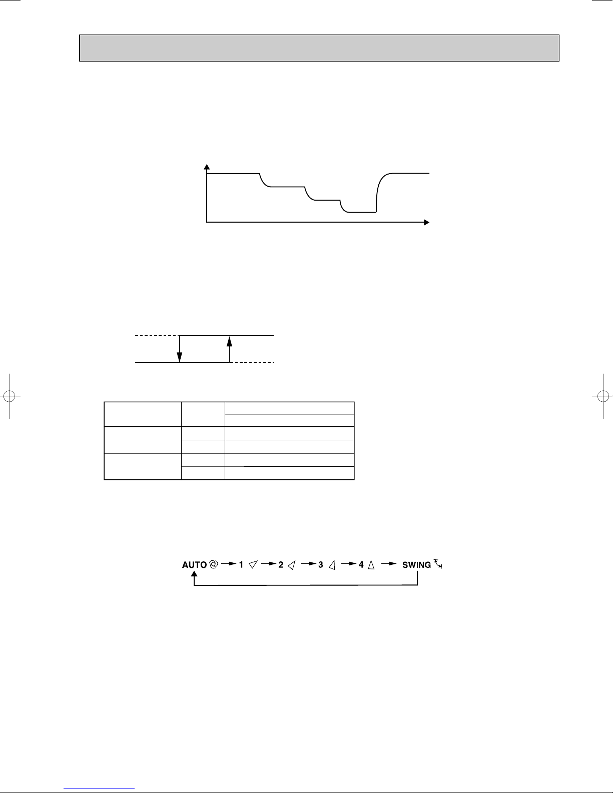
6-5. INDOOR FAN MOTOR CONTROL
COOL
Fan speed
Up
Down
Up
Down
Mode
HEAT
Compressor frequency
MUZ-GA35
<Relation between compressor frequency and fan speed>
54Hz
41Hz
54Hz
41Hz
Up
Down
Fan speed
High
Low
Compressor frequency
Min.
Max.
(1) Rotational frequency feedback control
The indoor fan motor is equipped with a rotational frequency sensor, and outputs signal to the microprocessor to feedback
the rotational frequency. Comparing the current rotational frequency with the target rotational frequency (Super High, High,
Med., Low), the microprocessor adjusts fan motor electric current to make the current rotational frequency close to the
target rotational frequency. With this control, when the fan speed is switched, the rotational frequency changes smoothly.
Rotational frequency
Super High
High
Med.
Low
Super High
time
(2) Fan motor lock-up protection
When the rotational frequency feedback signal has not output for 12 seconds, (or when the microprocessor cannot
detect the signal for 12 seconds) energizing to the fan motor is stopped. Then the microprocessor retries detection 3
times every 30 seconds. If the microprocessor still cannot detect the signal, the fan motor is regarded locked-up. When
the fan motor lock-up, POWER lamp flashes on and off to show the fan motor abnormality.
6-6. OUTDOOR FAN MOTOR CONTROL MUZ-GA35
Fan speed is switched according to the compressor frequency.
6-7. AUTO VANE OPERATION
1. Horizontal vane
(1) Vane motor drive
These models are equipped with a stepping motor for the horizontal vane. The rotating direction, speed, and angle of
the motor are controlled by pulse signals (approx. 12V) transmitted from indoor microprocessor.
(2) The horizontal vane angle and mode change as follows by pressing VANE CONTROL button.
(3) Positioning
The vane presses the vane stopper once to confirm the standard position and then moves to the set angle.
Confirming of standard position is performed in case of follows.
(a) When the operation starts or finishes (including timer operation).
(b) When the test run starts.
(c) When multi-standby starts or finishes.
77

(4) VANE AUTO ( ) mode
Horizontal
position
The air conditioner starts heating operation approx. 3 minutes
after the vane has moved to the
horizontal position.
• Sometimes the area
around your feet may not
warm. To warn the area
around the feet, set the
horizontal vane to
(AUTO) or the downwardblowing position.
• When VANE CONTROL
button is pressed again,
the vane returns to the
previously-set position
and the air conditioner
starts the heating operation
in approx. 3minutes.
To change the air
flow direction
When to use this function?
Use this function if you don’t
want the air from the indoor
unit to blow directly onto your
body.
• Depending on the shape of
the room,the air may blow
directly onto your body.
• Press VANE CONTROL
button again to return the
vane to the previously-set
position.
The air conditioner starts the
cooling or drying operation
approx. 3 minutes after the
vane has moved to the horizontal position.
•
Pressing and holding
VANE CONTROL
button for 2 seconds
or more causes
the horizontal vane
to reverse and
move to horizontal
position.
COOL/DRY
HEAT
NOTE:
• If you make the air flow not to blow directly onto your body by pressing VANE CONTROL button,
the compressor stops for 3 minutes even during the operation of the air conditioner.
• The air conditioner operates with decreased air flow until the compressor turns on again.
(9) To change the air flow direction not to blow directly onto your body.
Horizontal
position
When VANE CONTROL
button is pressed again,
the vane returns to the
previously-set position
and the air conditioner
starts the cooling or
drying operation in
approx. 3minutes.
The microprocessor automatically determines the vane angle and operation to make the optimum room temperature distribution.
COOL and DRY operation
Vane angle is fixed to Horizontal position.
HEAT operation
Vane angle is fixed to Angle 4.
(5) STOP (operation OFF) and ON-TIMER standby
When the following cases occur, the horizontal vane returns to the closed position.
(a) When OPERATE/STOP (ON/OFF) button is pressed (POWER OFF).
(b) When the operation is stopped by the emergency operation.
(c) When ON-TIMER is ON standby.
(6) Dew prevention
During COOL or DRY operation with the vane angle at Angle 2 ~ 4 when the compressor cumulative operation time
exceeds 1 hour, the vane angle automatically changes to Angle 1 for dew prevention.
(7) SWING MODE ( )
By selecting SWING mode with VANE CONTROLbutton, the horizontal vane swings vertically. The remote controller
displays “”. SWING mode is cancelled when VANE CONTROLbutton is pressed once again.
(8) Cold air prevention in HEAT operation
When any of the following conditions occurs in HEAT operation, the vane angle changes to Horizontal position automatically to prevent cold air blowing on users.
① Compressor is not operating.
➁ Defrosting is performed.
➂ Indoor coil thermistor RT12 reads 24: or below.
➃ Indoor coil thermistor RT12 temperature is raising from 24°C or below, but it does not exceed 39:.
⑤ For about 3 minutes after compressor starts.
NOTE: When 2 or more indoor units are operated with multi outdoor unit, even if any indoor unit turns thermostat off,
this control doesn’t work in the indoor unit.
78

(
START
STOP
START
STOP
10
) ECONO COOL ( ) operation (ECONOmical operation)
When ECONO COOL button is pressed in COOL mode, set temperature is automatically set 2°C higher.
Also the horizontal vane swings in various cycle according to the temperature of indoor heat exchanger(RT12).
SWING operation makes you feel cooler than set temperature. So, even though the set temperature is higher, the air
conditioner can keep comfort. As a result, energy can be saved.
ECONO COOL operation is cancelled when ECONO COOL button is pressed once again or VANE CONTROL
button is pressed or change to other operation mode.
<SWING operation>
In swing operation of ECONO COOL operation mode, the initial air flow direction is adjusted to “Horizontal”.
According to the temperature of indoor coil thermistor RT12 at starting of this operation, next downward blow time is
decided. Then when the downward blow has been finished, next horizontal blow time is decided.
For initial 10 minutes the swing operation is performed in table G~H for quick cooling.
Also, after 10 minutes when the difference of set temperature and room temperature is more than 2:, the swing operation is performed in table D~H for more cooling.
The air conditioner repeats the swing operation in various cycle as follows.
Temperature of indoor
coil thermistor RT12
A
B
C
D
E
F
G
H
15°C or less
15°C to 17°C
17°C to 18°C
18°C to 20°C
20°C to 21°C
21°C to 22°C
22°C to 24°C
more than 24°C
Downward blow time
(second)
2
5
8
11
14
17
20
23
Horizontal blow time
(second)
23
20
17
14
11
8
5
2
6-8. TIMER OPERATION
1. How to set the timer
(1) Press OPERATE/STOP (ON/OFF) button to start the air conditioner.
(2) Check that the current time is set correctly.
NOTE : Timer operation will not work without setting the current time. Initially “AM0:00” blinks at the current time display of
TIME MONITOR, so set the current time correctly with CLOCK SET button.
ON timer setting
(1) Press ON-TIMER button( ) to set ON timer.
Each time the button is pressed, ON timer mode alternates between ON and OFF.
(2) Set the time of the timer using TIME SET buttons ( and ).
Each time FORWARD button( ) is pressed, the set time increases by 10 minutes; each time BACKWARD
button ( ) is pressed, the set time decreases by 10 minutes.
OFF timer setting
(1) Press OFF-TIMER button ( ) to set OFF timer.
Each time the button is pressed, OFF timer mode alternates between ON and OFF.
(2) Set the time of the timer using TIME SET buttons ( and ).
Each time FORWARD button ( ) is pressed, the set time increases by 10 minutes; each time BACKWARD ( )
button is pressed, the set time decreases by 10 minutes.
2. Cancel
TIMER setting can be cancelled with ON/OFF TIMER buttons.
To cancel ON timer, press ON-TIMER button ( ).
To cancel OFF timer, press OFF-TIMER button( ).
TIMER is cancelled and the display of set time disappears.
79

EMERGENCY OPERATION switch
E.O.
SW
Operation mode COOL HEAT
Set temperature
24:
24:
Fan speed Medium Medium
Horizontal vane Auto Auto
The operation mode is indicated by the Operation
Indicator lamp on the indoor unit as following
Operation indicator lamp
Press again <Heat>
Press once <Cool>
Press once again <Stop>
Not lighted
Lighted
PROGRAM TIMER
• OFF timer and ON timer can be used in combination. The timer of the set time that is reached first will operate first.
• “” and “” display shows the order of OFF timer and ON timer operation.
(Example 1) The current time is 8:00 PM.
The unit turns off at 11:00 PM, and on at 6:00 AM.
(Example 2) The current time is 11:00 AM.
The unit turns on at 5:00 PM, and off at 9:00 PM.
NOTE : If the main power is turned off or a power failure occurs while AUTO START/STOP timer is active, the timer setting is
cancelled. As these models are equipped with an auto restart function, the air conditioner starts operating with timer
cancelled when power is restored.
6-9. EMERGENCY/TEST OPERATION
In case of test run operation or emergency operation, use EMERGENCY OPERATION switch on the front of the indoor
unit. Emergency operation is available when the remote controller is missing, has failed or the batteries of the remote
controller run down. The unit will start and AREAlamp will light.
The first 30 minutes of operation is the test run operation. This operation is for servicing. The Indoor fan speed runs at
High speed and the system is in continuous operation (The thermostat in ON).
After 30 minutes of test run operation, the system shifts to EMERGENCY COOL / HEAT MODE with a set temperature of
24°C. The fan speed shifts to Med..
The coil frost prevention works even in emergency operation, and defrosting too.
In the test run or emergency operation, the horizontal vane operates in VANE AUTO ( ) mode.
Emergency operation continues until EMERGENCY OPERATION switch is pressed once or twice or the unit receives any
signal from the remote controller. In case of latter, normal operation will start.
NOTE : Do not press EMERGENCY OPERATION switch during normal operation.
80

6-10. INVERTER SYSTEM CONTROL
POWER P.C. BOARD
Power
supply
INVERTER P.C. BOARD
R64A R64B
CT
TR821
DB65
X64
L62 L63
C63A
C63B
C63C
DB61
L61
P
W
V
U
N
CT761
CT781
IPM
U
W
MC
V
+
Booster chopper circucuit
SYMBOL
IPM
C63A/C63B/C63C
CT761/CT781
CT
DB61
R64A, R64B
X64
DB65
TR821
L61
NAME
INTELLIGENT POWER MODULE
SMOOTHING CAPACITOR
CURRENT TRANSFORMER
CURRENT TRANSFORMER
DIODE MODULE
CURRENT-LIMITING RESISTOR
RELAY
DIODE MODULE
SWITCHING POWER TRANSISTOR
REACTOR
FUNCTION
It supplies three-phase AC power to compressor.
It stabilizes the DC voltage.
It measures the current of the compressor motor.
It measures the value of current which is supplied to the main power
supply circuit.
It converts the AC voltage to DC voltage.
It absorbs the rush current not to run into the main power supply circuit
when the electricity turns ON.
It short-circuits the resistance which restricts rush current during the
normal operation after the compressor startup.
Booster
chopper
circuit
Function of main parts
It improves power factor.
It rectifies AC and controls its voltage.
6-10-2. Outline of main power supply circuit
1. At the start of operation
Main power supply circuit is formed when X64 (Relay) is turned ON at compressor startup.
To prevent rush current from running into the circuit when power supply is turned ON,
R64A and R64B (Current-limitting resistor) are placed in sub circuit.
2. At normal operation
1 When AC runs into POWER P.C. board, its external noise is eliminated in the noise filter circuit.
2 After noise is eliminated from AC, it is rectified to DC by DB61 (Diode module).
3 DC voltage, to which AC has been rectified by process 2, is stabilized by C63A, C63B and C63C (Smoothing capacitor)
and supplied to IPM (Intelligent power module).
4 DC voltage, which has been stabilized in process 3, is converted to three-phase AC by IPM and supplied to
compressor.
5 CT761 and CT781 (Current Transformer), which are placed in the power supply circuit to compressor, are used to
measure the value of phase current and locate the polar direction of rotor with algorithm. PWM (Pulse width modulation)
controls impressed voltage and frequency with those information.
6-10-1. Inverter main power supply circuit
81

4. Intelligent power module
IPM consists of the following components
· IGBT (x6) : Converts DC waveform to three-phase AC waveform and outputs it.
· Drive Circuit : Drives transistors.
· Protection circuit : Protects transistors from overcurrent.
Since the above components are all integrated in IPM, IPM has a merit to make the control circuit simplify and miniaturize.
5. Smoothing capacitor
C63A, C63B and C63C stabilize the DC voltage and supply it to IPM.
6. Elimination of electrical noice
Noise filter circuit, which is formed by *CMC COILS capacitors placed on the POWER P.C. board, eliminates electrical
noise of AC power that is supplied to main power supply circuit. And this circuit prevents the electrical noise generated in
the inverter circuit from leaking out.
*CMC COILS; Common mode choke coils
Outline of simple partial switching method
In conventional inverter models, diode module rectifies AC voltage to DC voltage, smoothing capacitor makes its DC waveform
smooth, and IPM converts its DC voltage to imitated AC voltage again in order to drive the compressor motor.
However, it has been difficult to meet IEC harmonic current emission standard by above circuit because harmonic gets
generated in the input current waveform and power factor gets down. The simple partial switching method with PAM, which has
been adopted this time, places and utilizes the booster chopper circuit (L61, DB65 and TR821) before rectifying AC voltage in
the general passive-method converter circuit. As harmonic gets suppressed and the peak of waveform gets lower by adding
booster chopper circuit as mentioned above and by synchronizing the timing of one-time switching with the zero-cross point of
waveform, the input current waveform can be improved and the requirement of IEC harmonic current emission standard can be
satisfied. Since the switching times is just once by synchronizing with the zero cross point, this simple partial switching method
has the feature of lower energy loss compared to active filter method. In addition, output and efficiency is enhanced by
combining with vector-controlled inverter in order to boost the voltage of power supplied to IPM.
Input current waveform without PAM Input current waveform with PAM
Due to the time of no electricity;
· Power factor gets worse.
· Harmonic gets increased.
Input voltage
Release of energy stored in L
Energized time is
extended by optimization
of L inductance.
Peak gets down.
Energized time is short in
case L inductance is small.
No electricity runs into
diode module because the
voltage at both sides of smoothing
capacitor is higher than input voltage.
Compulsory energizing
by switching.
Input current
Owing to the increase of energized time;
· Power factor gets better.
· Harmonic gets suppressed.
3. Purpose of PAM adoption
PAM : Pulse Amplitude Modulation
PAM has been adopted for the efficiency improvement and the adaptation to IEC harmonic current emission standard.
Sine wave control
In these air conditioners, compressor equips brushless DC motor which doesn't have Hall element.
In short, the motor is sensorless. However, it's necessary to locate the polar direction of rotor in order to drive brushless DC
motor efficiently. The general detection method of the polar direction for such a DC motor is to locate it from the voltage induced
by unenergized stator.
Therefore, It is necessary to have a certain period of time in which the stator is being unenergized for the rotor position
detection when the voltage of supplied power is impressed.
So the motor has been driven by square wave control (the conventional motor drive system) which energizes the motor only
when the range of electrical angle is within 120_ because it is forced to be unenergized within 30_ at start & end of one heap
in one waveform cycle (180_) when the voltage is impressed.
However, torque pulsation occurs at rotation in this method when the current-carrying phases are switched over to other
phases in sequence. Therefore, sine wave control system is adopted for these air conditioners because it can make the
phase-to-phase current waveform smoother (sine wave) in order to drive the motor more efficiently and smoothly.
82

1 hour
Time
Maximum
frequency
Upper limit
frequency
Rated frequency or less
6-11. OPERATIONAL FREQUENCY CONTROL OF OUTDOOR UNIT
Rotor
Rotor Position Signal
Permanent magnet is embedded.
Necessary
DC Motor
Excited by magnetic field of stator
Unnecessary
AC Motor
6-10-3. Characteristics of sine wave control in case of brushless DC motor
● Although ordinary three-phase induction motor requires energy to excite the magnetic field of rotor, brushless DC motor
doesn't need it. So, higher efficiency and torque are provided.
● This control provides the most efficient waveform corresponding to the rotation times of compressor motor.
● The rotation can be set to higher compared to the conventional motor drive system. So, the time in which air conditioner
can be operated with energy saved is longer than conventional models. This can save annual electric consumption.
● Compared to square wave control, the torque pulsation is reduced at rotation so that the motor operates more quietly.
● Since response and efficiency of motor are enhanced in sine wave control, finer adjustment can be provided.
w In brushless DC motor, permanent magnet is embedded in the rotor. Therefore, it doesn't require energy to excite the rotor
like AC motor does. However, it's necessary to control the frequency of three-phase AC current supplied to the stator
according to the polar direction of magnet embedded in the rotor so as to drive the motor efficiently. Controlling three-phase
AC current frequency also means controlling the timing to switch the polarity of stator. Therefore, the polar direction of rotor
needs to be detected.
6-10-4. Control Method of Rotation Times
Sine wave control makes the current transformers conduct real time detection of the value of the current running into the motor,
locates the rotor position from the detected value, and decides if voltage should be impressed and if frequency should be chan ged.
Compared to the conventional control and rotor position detection method, sine wave control can provide finer adjustment of the
voltage of supplied power. The value of the current running into the motor is determined by each motor characteristic.
1. Outline
The operational frequency is as following:
First, the target operational frequency is set based on the difference between the room temperature and the set temperature.
Second, the target operational frequency is regulated by discharge temperature protection, high pressure protection,
electric current protection and overload protection and also by the maximum/minimum frequency.
2. Maximum/minimum frequency in each operation mode
COOL
Applied
model
MUZ-GA25VA
MUZ-GA25VAH
MUZ-GA35VA
MUZ-GA35VAH
w The operation frequency in COOL mode is restricted the upper limit frequency after 1 hour as shown below for
dew prevention.
It is rated frequency or less.
Minimum
frequency
28
28 88
Rated
frequency
65
Maximum
frequency
70
98
Minimum
frequency
48
45
HEAT
Rated
frequency
85 105
96 105 28
Maximum
frequency
Minimum
frequency
28
83
DRY
Maximum
frequency
40
58

6-12. EXPANSION VALVE CONTROL (LEV CONTROL) MUZ-GA35
(1) Outline of LEV control
The LEV basic control is comprised of setting LEV opening degree to the standard opening degrees set for each opera-
tional frequency of the compressor. However, when any change in indoor/outdoor temperatures or other factors cause
air conditioning load fluctuation, the LEV control also works to correct LEV opening degree based on discharge temperature (Shell temperature) of the compressor, developing the unit’s performance.
Control range from minimum 33 pulse to maximum 500 pulse.
Actuating speed LEV opens 40 pulse/second and close 90 pulse/second
Opening degree adjustment LEV opening degree is always adjusted in opening direction.
standard
specification
Unit OFF LEV remains at maximum opening degree (reaches maxi-
Remote controller ON LEV is positioned. (first full-closed at zero pulse and then
(When reducing the opening degree, LEV is once overclosed, and then adjusted to the proper degree by opening.
mum opening degree approximate in 15 minutes after compressor stops)
positioned.)
COOL · DRY MODE
During 1 to 5 minutes after compressor starts
HEAT MODE
During 1 to 15 minutes after compressor starts
More than COOL, DRY: 5/ HEAT: 15 minutes have
passed since compressor start-up
general operation
Thermostat OFF LEV is adjusted to exclusive opening degree for thermostat
Thermostat ON LEV is controlled in the same way as that after the compres-
Defrosting in HEAT mode LEV is adjusted to open 500 pulse.
LEV is fixed to standard opening degree according to operational frequency of compressor.
LEV opening degree is corrected to get target discharge
temperature of compressor.
(For discharge temperature lower than target temperature,
LEV is corrected in closing direction.)
(For discharge temperature higher than target temperature,
LEV is corrected in opening direction.)
wIt may take more than 30 minutes to reach target temperature, depending on operating conditions.
OFF.
sor has started up.
84

(2) Time chart
OFF Time
Time
ON
Operational frequency
of the compressor
Commanded
to open
Standard
opening
degree
Opening degree is
corrected according
to discharge
temperature.
Positioning
Air conditioner ON
Air conditioner OFF
(thermostat off)
LEV opening degree
about 5 minutes <COOL, DRY>
about 15 minutes <HEAT>
06
05
04
03
02
01
LEV opening degree
A(target discharge temperature)
B
C
D
E
F
30 50 70
Operational frequency of the compressor
90 110 130
(Hz)
(3) Control data
(a) Reference value of target discharge temperature
(COOL/HEAT :)
Applied model
MUZ-GA35VA
MUZ-GA35VAH
ABCDEF
47/41
53/48 58/55
In COOL operation, the two indoor coil thermistors (one main and one sub) sense temperature ununiformity (super
heat) at the heat exchanger, and when temperature difference have developed, the indoor coil thermistors adjust
LEV opening degree to get approximate 10 degrees lower temperature than the target temperature in the table
above, thus diminishing super heat.
(b) Reference value of LEV standard opening degree
(COOL/ HEAT pulse)
Applied model
MUZ-GA35VA
MUZ-GA35VAH
01 02 03 04 05 06
150/110
190/110 240/150
63/60
280/170
67/65 67/65
310/200
340/230
85

MSZ-GA50VA MUZ-GA50VA
MSZ-GA60VA MUZ-GA60VA
MSZ-GA71VA MUZ-GA71VA
WIRELESS REMOTE CONTROLLER
Signal transmitting section
Operation display section
OPERATE /STOP
(ON /OFF)button
ON/OFF
TOO
WARM
TOO
COOL
TEMPERATURE buttons
Indication of remote controller
model is on back.
WIDE VANE button
(Vertical vane button)
FAN SPEED CONTROL button
OPERATION SELECT button
ECONO COOL button
LONG button
RESET button
LONG
OFF-TIMER button
ON-TIMER button
TIME SET buttons
FORWARD button
BACKWARD button
CLOCK SET button
VANE CONTROL button
(Horizontal vane button)
Once the operation mode is set, the same operation mode can be repeated by simply turning OPERATE/STOP
(ON/OFF) button ON.
Indoor unit receives the signal with a beep tone.
When the system turns off, 3-minute time delay will operate to protect system from overload and compressor will not
restart for 3 minutes.
6-13. COOL ( ) OPERATION
(1) Press OPERATE/STOP(ON/OFF) button.
OPERATION INDICATOR lamp of the indoor unit turns on with a beep tone.
(2) Select COOL mode with OPERATION SELECT button.
(3) Press TEMPERATURE buttons (TOO WARM or TOO COOL button)to select the desired temperature.
The setting range is 16 ~ 31°C
1. Thermostat control
Thermostat is ON or OFF by difference between room temperature and set temperature
Initial temperature difference Thermostat
Room temperature minus set temperature : -1.0 : or more··············································ON
Room temperature minus set temperature : less than -1.0 :············································OFF
86
Difference between room
temperature and set temperature during operation.
Set temperature
-1.0 :
-0.7 :

35
30
25
20
15
10
:
10 15 20 25 30 35
Set temperature
Initial room temperature
Set temperature and
initial room temperature in dry mode
:
2. Indoor fan speed control
Indoor fan operates continuously at the set speed by FAN SPEED CONTROL button
regardless of the thermostat’s OFF-ON.
In AUTO the fan speed is as follows.
Initial temperature difference
Fan speed
Difference between room
temperature and set temperature during operation
Room temperature minus set temperature : 1.7 : or more ········································High
Room temperature minus set temperature : Between 1 and 1.7 :
··································
Room temperature minus set temperature : less than 1 : ········································Low
Med.
1 :
3 :
1.7 :
3. Coil frost prevention
Temperature control
When indoor coil thermistor detects following temperature for 90 seconds, operational frequency
of compressor is controlled according to the following table.
Temperature of indoor coil thermistor
10°C or more
Operation frequency
Normal (variable)
8°C to 10°C Raise 6Hz
6°C to 8°C
3°C to 6°C
Fixed
Lower 3Hz
Lower 6Hz
3°C or less
Compressor is turned OFF for 5 minutes when temperature of
indoor coil thermistor continues 3°C or less for 5 minutes or more.
The indoor fan maintains the actual speed of the moment.
4. Low outside temperature operation
If the outside temperature falls to 18°C or less during operation in COOL mode, the unit enters the low outside temperature
operation mode.
<Operation>
(1) If the unit enters the low outside temperature operation mode, the outside fan rotation speed gets slow down.
(2) Even when the unit is in the "thermostat-off" status under the low outside temperature operation mode, the outside fan
rotation does not stop.
(3) Outside temperature detecting control
In this mode to detect the exact outside temperature the compressor turns OFF with the outdoor fan ON for 3 minutes
once 1 hour; if the outside temperature rises over 18°C, the unit goes back to the normal COOL mode, and if the outside
temperature is still 18°C or less, the unit stays in the low outside temperature operation mode.
(4) Dew drop prevention
When the ambient temperature thermistor RT65 reads -12: or less, as coil frost or dew drop from indoor unit may
occur, the compressor turns OFF with the outdoor fan ON for prevention of them.
WOther protections work as well as in the normal COOL mode.
6-14. DRY ( ) OPERATION
(1) Press OPERATE/STOP(ON/OFF) button.
OPERATION INDICATOR lamp of the indoor unit turns on with a
beep tone.
(2) Select DRY mode with OPERATION SELECT button.
(3) The microprocessor reads the room temperature and determines
the set temperature. Set temperature is as shown on the right
chart.
The system for dry operation uses the same refrigerant circuit as the cooling circuit.
The compressor and the indoor fan are controlled by the room temperature.
By such controls, indoor flow amounts will be reduced in order to lower humidity without much room temperature decrease.
87

Difference between room
1. Thermostat control
Thermostat is ON or OFF by difference between room temperature and set temperature.
Initial temperature difference Thermostat
temperature and set temperature during operation
Set temperature
Room temperature minus set temperature : -1.0 : or more··············································ON
Room temperature minus set temperature : less than -1.0 :············································OFF
-1.0 :
2. Indoor fan speed control
-0.7 :
Indoor fan operates at the set speed by FAN SPEED CONTROL button.
When thermostat OFF (compressor OFF) fan speed becomes Very Low.
Difference between room
temperature and set tempera-
Initial temperature difference
Fan speed
ture during operation
Room temperature minus set temperature : 1.7 : or more ········································High
Room temperature minus set temperature : Between 1 and 1.7 :
··································
Room temperature minus set temperature : less than 1 : ········································Low
Med.
1 :
1.7 :
3. Coil frost prevention
Coil frost prevention is as same as COOL mode. (6-13.3.)
The indoor fan maintains the actual speed of the moment. However, when coil frost prevention works while the compressor
is not operating it’s speed becomes the set speed.
4. Low outside temperature operation
Low outside temperature operation is as same as COOL mode. (6-13.4.)
6-15. HEAT ( ) OPERATION
(1) Press OPERATE/STOP(ON/OFF) button.
OPERATION INDICATOR lamp of the indoor unit turns on with a beep tone.
(2) Select HEAT mode with OPERATION SELECT button.
(3) Press TEMPERATURE buttons (TOO WARM or TOO COOL button) to select the desired temperature.
The setting range is 16 ~ 31°C.
1. Thermostat control
Thermostat is ON or OFF by difference between room temperature and set temperature.
Initial temperature difference Thermostat
Room temperature minus set temperature : less than 2.0 :··············································ON
Room temperature minus set temperature : 2.0 : or more················································OFF
2. Indoor fan speed control
(1) Indoor fan operates at the set speed by FAN SPEED CONTROL button.
In Auto the fan speed is as follows.
Initial temperature difference
Set temperature minus room temperature: 2 :or more
Set temperature minus room temperature:
Between 1 and 2 : ····································
Set temperature minus room temperature: less than 1
·················································· High
:·················································
Fan speed
Med.
Low
(2) Cold air prevention control
1 When the compressor is not operating,
(1) if the temperature of room temperature thermistor RT11 is 15°C or less, or RT12 is less than 18°C,
the fan stops.
(2) if the temperature of room temperature thermistor RT11 is more than 15°C, or RT12 is more than 18°C,
the fan operates at Very Low.
2 When the compressor is operating,
(1) if the temperature of RT12 is 18°C or more, the fan operates at set speed.
(2) if the temperature of RT12 is less than 18°C and
(1) if heating operation starts after defrosting, the fan stops.
(2) if the temperature of room temperature thermistor RT11 is 15°C or less, the fan stops.
(3) if the temperature of room temperature thermistor RT11 is more than 15°C, the fan operates at Very Low.
Difference between room
temperature and set temperature during operation
Set temperature
2.0 :
1.7 :
Difference between room
temperature and set temperature during operation
2 :
1 :
1.7 :
3 :
4 :
NOTE : When 3 minutes have passed since the compressor started operation, this control is released regardless of the
temperature of RT11 and RT12.
88

set position
set speed
set position
set speed
Indoor fan
Compressor normal
Outdoor fan
R.V. coil
(21S4)
OFF (COOL)
OFF
Maximum frequency
horizontal
Horizontal vane
Very Low (temperature of indoor coil thermistor > 18:)
30
seconds
30
seconds
30
seconds
40
seconds
5 seconds 5 seconds
40
seconds
OFF
OFF
OFF
ON (HEAT)
ON ON
ON (HEAT)
3. High pressure protection
In HEAT operation the indoor coil thermistor detects the temperature of the indoor heat exchanger. The compressor operational frequency is controlled to prevent the condensing pressure from increasing excessively.
4. Overload starting
When the room temperature thermistor RT11 reads 18°C or more, the compressor runs with its maximum frequency regulated for 10 minutes after the start-up.
5. Defrosting
(1) Starting conditions of defrosting
When the following conditions a) ~ c) are satisfied, the defrosting starts.
a) The defrost thermistor reads -3°C or less.
b) The cumulative operation time of the compressor has reached any of the set valuesw (31, 35, 45, 55, 65, 75, 85, 95,
105, 115, 150 minutes).
c) More than 5 minutes have passed since the start-up of the compressor.
w Set value of compressor operation time(hereinafter referred to as defrost interval)
This is decided by the temperature of defrost thermistor and ambient temperature thermistor, the previous defrosting
time. For example, the first defrost interval is 40 minutes long, and the second is 45 minutes long. The third and sub-
sequent intervals are set to be longer, and less frequent, depending on defrosting time.
The third and subsequent defrost intervals follow any of the three patterns …5 or 10 to 20 minutes longer, the same,
or 5 or 10 to 20 minutes shorter compared with the previous defrost interval … with the longest 125 minutes and the
shortest 40 minutes.
(2) Releasing conditions of defrosting
Defrosting is released when any of the following conditions is satisfied:
a) The defrost thermistor continues to read 15°C or more for 30 seconds.
b) Defrosting time has exceeded 10 minutes.
c) Any other mode than HEAT mode is set during defrosting.
Time chart of defrosting in HEAT mode (reverse type)
<indoor unit>
<outdoor unit>
89

6-16. AUTO CHANGE OVER ··· AUTO MODE OPERATION
High
Med.
Low
High
Rotational frequency
time
Once desired temperature is set, unit operation is switched automatically between COOL and HEAT operation.
1. Mode selection
(1) Initial mode
At first indoor unit operates only indoor fan with outdoor unit OFF for 3 minutes to detect present room temperature.
Following the conditions below, operation mode is selected.
1 If the room temperature thermistor RT11 reads more than set temperature, COOL mode is selected.
2 If the room temperature thermistor RT11 reads set temperature or less, HEAT mode is selected.
(2) Mode change
In case of the following conditions the operation mode is changed.
1 COOL mode changes to HEAT mode when 15 minutes have passed with the room temperature 2 degrees below the
set temperature.
2 HEAT mode changes to COOL mode when 15 minutes have passed with the room temperature 2 degrees above the
set temperature.
In the other cases than the above conditions, the present operation mode is continued.
NOTE1: Mode selection is performed when multi standby (refer to NOTE2) is released and the unit starts operation with
ON-timer.
NOTE2: If two or more indoor units are operating in multi system, there might be a case that the indoor unit, which is
operating in AUTO ( ), cannot change over the other operating mode (COOL HEAT) and becomes a
state of standby.
(3) Indoor fan control/ Vane control
As the indoor fan speed and the horizontal vane position depend on the selected operation mode, when the operation
mode changes over, they change to the exclusive ones.
6-17. INDOOR FAN MOTOR CONTROL
(1) Rotational frequency feedback control
The indoor fan motor is equipped with a rotational frequency sensor, and outputs signal to the microprocessor to feedback
the rotational frequency. Comparing the current rotational frequency with the target rotational frequency (High, Med., Low),
the microprocessor adjusts fan motor electric current to make the current rotational frequency close to the target
rotational frequency. With this control, when the fan speed is switched, the rotational frequency changes smoothly.
(2) Fan motor lock-up protection
When the rotational frequency feedback signal has not output for 12 seconds, (or when the microprocessor cannot
detect the signal for 12 seconds) energizing to the fan motor is stopped. Then the microprocessor retries detection 3
times every 30 seconds. If the microprocessor still cannot detect the signal, the fan motor is regarded locked-up. When
the fan motor lock-up, POWER lamp flashes on and off to show the fan motor abnormality.
90

6-18. OUTDOOR FAN MOTOR CONTROL
COOL
Fan speed
Up
Down
Up
Down
Mode
HEAT
Compressor frequency
MUZ-GA50/GA60
MUZ-GA71
<Relation between compressor frequency and fan speed>
54Hz
39Hz
54Hz
39Hz
44Hz
33Hz
44Hz
33Hz
Up
Down
Fan speed
High
Low
Compressor frequency
Min.
Max.
Fan speed is switched according to the compressor frequency.
6-19. AUTO VANE OPERATION
1. Horizontal vane
(1) Vane motor drive
These models are equipped with a stepping motor for the horizontal vane. The rotating direction, speed, and angle of
the motor are controlled by pulse signals (approx. 12V) transmitted from indoor microprocessor.
(2) The horizontal vane angle and mode changes as follows by pressing VANE CONTROL button.
(3) Positioning
The vane presses the vane stopper once to confirm the standard position and then moves to the set angle.
Confirming of standard position is performed in case of follows.
(a) When the power supply turns ON.
(b) When the operation starts or finishes (including timer operation).
(c) When the test run starts.
(d) When multi-standby starts or finishes.
(4) VANE AUTO ( ) mode
The microprocessor automatically determines the horizontal vane angle and operation to make the optimum room temperature distribution.
COOL and DRY operation
Vane angle is fixed to Angle 1.
(5) STOP (operation OFF) and ON-TIMER standby
When the following cases occur, the horizontal vane returns to the closed position.
(a) When OPERATE/STOP (ON/OFF) button is pressed (POWER OFF).
(b) When the operation is stopped by the emergency operation.
(c) When ON-TIMER is ON standby.
(6) Dew prevention
During COOL or DRY operation with the vane angle at Angle 4 or 5 when the compressor cumulative operation time
exceeds 1 hour, the vane angle automatically changes to Angle 1 for dew prevention.
HEAT operation
Vane angle is fixed to Angle 4.
91

Horizontal vane
Set position
Horizontal Position
22:18:
Released
Cold Air Prevention
(7) SWING MODE ( )
By selecting SWING mode with VANE CONTROLbutton, the horizontal vane swings vertically. The remote controller
displays “”. SWING mode is cancelled when VANE CONTROLbutton is pressed once again.
(8) Cold air prevention in HEAT operation
When any of the following conditions occurs in HEAT operation, the vane angle changes to Horizontal position automatically to prevent cold air blowing on users.
① Compressor is not operating.
➁ Defrosting is performed.
➂ Indoor coil thermistor RT12 reads 18: or below.
➃ Indoor coil thermistor RT12 temperature is raising from 18°C or below, but it does not exceed 22:.
Indoor coil thermistor RT12 temperature
NOTE1: If the temperature of RT12 reads from 18: to 22: at the air conditioner starting, this control works.
NOTE2: When 2 or more indoor units are operated with multi outdoor unit, even if any indoor unit turns thermostat off,
this control doesn’t work in the indoor unit.
(9) ECONO COOL ( ) operation (ECONOmical operation)
When ECONO COOL button is pressed in COOL mode, set temperature is automatically set 2°C higher.
Also the horizontal vane swings in various cycle according to the temperature of indoor heat exchanger(RT12).
SWING operation makes you feel cooler than set temperature. So, even though the set temperature is higher, the air
conditioner can keep comfort. As a result, energy can be saved.
ECONO COOL operation is cancelled when ECONO COOL button is pressed once again or VANE CONTROL
button is pressed or change to other operation mode.
SWING operation
In swing operation of ECONO COOL operation mode, the initial air flow direction is adjusted to “Horizontal”.
According to the temperature of indoor coil thermistor RT12 at starting of this operation, next downward blow time is
decided. Then when the downward blow has been finished, next horizontal blow time is decided.
For initial 10 minutes the swing operation is performed in table G~H for quick cooling.
Also, after 10 minutes when the difference of set temperature and room temperature is more than 2:, the swing operation is performed in table D~H for more cooling.
The air conditioner repeats the swing operation in various cycle as follows.
Temperature of indoor
coil thermistor RT12
A
B
C
D
E
F
G
H
15°C or less
15°C to 17°C
17°C to 18°C
18°C to 20°C
20°C to 21°C
21°C to 22°C
22°C to 24°C
more than 24°C
Downward blow time
(second)
2
5
8
11
14
17
20
23
Horizontal blow time
(second)
23
20
17
14
11
8
5
2
92

(10) LONG MODE ( )
COOL / DRY HEAT
Fan speed : Faster
Solid arrow : When the LONG mode is used.
Dotted arrow : When the LONG mode is not used.
61
23
45SWING
COOL and DRY
HEAT
About 100-
About 150-
Horizontal AIR FLOW blowing range
By pressing LONG button indoor fan speed becomes faster than setting fan speed on the remote controller, and the horizontal vane moves to the position for LONG mode. The remote controller displays “”. LONG mode is cancelled
when LONG button is pressed once again or VANE button is pressed or ECONO COOLbutton is pressed in COOL
mode.
• In the following example, the vertical vane is set to (front.).
2. Vertical vane
(1) Vane motor drive
These models are equipped with a stepping motor for the vertical vane. The rotating direction, speed, and angle of the
motor are controlled by pulse signals (approx. 12V) transmitted from microprocessor.
(2) The vertical vane angle and mode change as follows by pressing WIDE VANE button.
(3) Positioning
The vane is once pressed to the vane stopper to confirm the standard position and then set to the desired angle.
Confirming of standard position is performed in case of follows.
(a) When OPERATE/STOP(ON/OFF) button is pressed (POWER ON/OFF).
(b) When SWING is started or finished.
(c) When the power supply turns ON.
(4) SWING MODE ( )
By selecting SWING mode with WIDE VANE button, the vertical vane swings horizontally. The remote controller displays
“”. The vane moves right and left in the width of Angle 4 repeatedly.
(5) WIDE MODE ( )
By selecting WIDE mode with WIDE VANE button, indoor fan speed becomes faster than setting fan speed on the
remote controller (W). The remote controller displays “”.
NOTE : The position of vane angle 3, angle 4 and angle 5 are different in COOL operation and HEAT operation.
W Indoor fan speed becomes faster than setting fan speed on the remote controller even when or is
selected.
93
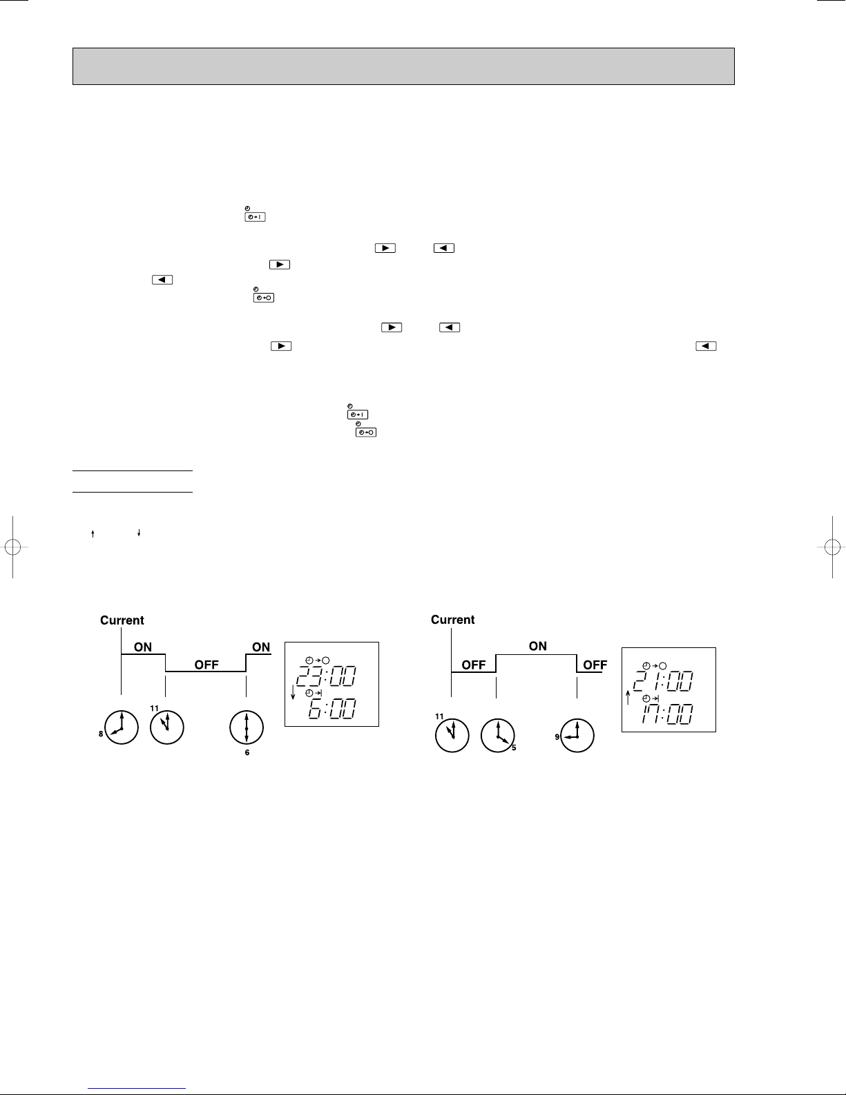
6-20. TIMER OPERATION
START
STOP
START
STOP
1. How to set the timer
(1) Press OPERATE/STOP (ON/OFF) button to start the air conditioner.
(2) Check that the current time is set correctly.
NOTE : Timer operation will not work without setting the current time. Initially “AM0:00” blinks at the current time display of
TIME MONITOR, so set the current time correctly with CLOCK SET button.
(3) Press ON-TIMER button( ) to set ON timer.
Each time the button is pressed, ON timer mode alternates between ON and OFF.
(4) Set the time of the timer using TIME SET buttons ( and ).
Each time FORWARD button( ) is pressed, the set time increases by 10 minutes; each time BACKWARD
button ( ) is pressed, the set time decreases by 10 minutes.
(5) Press OFF-TIMER button ( ) to set OFF timer.
Each time the button is pressed, OFF timer mode alternates between ON and OFF.
(6) Set the time of the timer using TIME SET buttons ( and ).
Each time FORWARD button ( ) is pressed, the set time increases by 10 minutes; each time BACKWARD ( )
button is pressed, the set time decreases by 10 minutes.
2. Cancel
TIMER setting can be cancelled with ON/OFF TIMER buttons.
To cancel ON timer, press ON-TIMER button ( ).
To cancel OFF timer, press OFF-TIMER button( ).
TIMER is cancelled and the display of set time disappears.
PROGRAM TIMER
• The OFF timer and ON timer can be used in combination. The timer of the set time that is reached first will operate first.
• “” and “” display shows the order of the OFF timer and the ON timer operation.
(Example 1) The current time is 8:00 PM.
The unit turns off at 11:00 PM, and on at 6:00 AM.
(Example 2) The current time is 11:00 AM.
The unit turns on at 5:00 PM, and off at 9:00 PM.
NOTE : If the main power is turned off or a power failure occurs while AUTO START/STOP timer is active, the timer setting is
cancelled. As these models are equipped with an auto restart function, the air conditioner starts operating with timer
cancelled at the same time that power is restored.
94

6-21. EMERGENCY / TEST OPERATION
EMERGENCY
OPERATION switch
Lighted
Not lighted
Press once <Cool>
Press again <Heat>
Press once again <Stop>
OPERATION INDICATOR lamp
• The following indication applies
regardless of the shape of lamp.
6-22. INVERTER SYSTEM CONTROL
6-22-1. Inverter main power supply circuit
SYMBOL
IPM
CB1~3
CT1~2
CT61
L
PFC
R64A, R64B
X64
NAME
INTELLIGENT POWER MODULE
SMOOTHING CAPACITOR
CURRENT TRANSFORMER
CURRENT TRANSFORMER
REACTOR
POWER FACTOR CONTROLLER
CURRENT-LIMITING RESISTOR
RELAY
FUNCTION
It supplies three-phase AC power to compressor.
It stabilizes the DC voltage.
It measures the current of the compressor motor.
It measures the current of the main power supply circuit.
It rectifies AC, controls its voltage and improves the power factor of
power supply.
It restricts rush current with the resistance.
It short-circuits the resistance which restricts rush current during the
compressor operates.
Function of main parts
W
MC
V
U
W
V
U
IPM
CB3
CB2
+CB1
PFC
CT61
N/F
CT2
CT1
X64
R64A/R64B
L
POWER
SUPPLY
POWER BOARD
P. C. BOARD
FILTERNOISE
In case of test run operation or emergency operation, use EMERGENCY OPERATION switch on the front of the indoor
unit. Emergency operation is available when the remote controller is missing, has failed or the batteries of remote controller run down. The unit will start and OPERATION INDICATOR lamp will light.
The first 30 minutes of operation is the test run operation. This operation is for servicing. The indoor fan speed runs at
High speed and the system is in continuous operation. (The thermostat is ON.)
After 30 minutes of test run operation, the system shifts to EMERGENCY COOL / HEAT MODE with a set temperature of
24°C.
The fan speed shifts to Med. speed.
The coil frost prevention works even in emergency operation, and defrosting too.
In the test run or emergency operation, the horizontal vane operates in VANE AUTO ( ) mode.
Emergency operation continues until EMERGENCY OPERATION switch is pressed once or twice or the unit receives any
signal from the remote controller. In case of latter, normal operation will start.
NOTE : Do not press EMERGENCY OPERATION switch during normal operation.
95

4. Power transistor module
IPM consists of the following components.
· Power Transistors (x6): Converts DC waveform to three-phase AC waveform and outputs it.
· Drive Circuit : Drives transistors.
· Protection circuit : Protects transistors from over current.
Since the above components are all integrated in IPM, IPM has a merit that can get the control circuit simplified and mini-
aturized.
6-22-2. Outline of main power supply circuit
1. At the start of operation
Main power supply circuit is formed when X64 (Relay) is turned ON at compressor startup.
To prevent rush current from running into the circuit when power supply is turned ON, R64A and R64B
(Current-limiting resistor) are placed in sub circuit.
2. At normal operation
1 When AC runs into noise filter P.C. board, its external noise is eliminated in the noise filter circuit.
2 After noise being eliminated from AC, it is rectified to DC by L (Reactor) and PFC (Power factor controller). If the operating
frequency becomes 25Hz or more, DC voltage rises to 370V.
3 DC voltage, to which has AC been rectified by process 2, is stabilized by CB1~3 (Smoothing capacitor) and supplied to
IPM (Intelligent power module).
4 The DC (Bus voltage), which has been stabilized in process 3, is converted to three-phase AC by IPM and supplied to
compressor.
5 CT1 and CT2 (Current Transformer), which are placed in the power supply circuit to compressor, are used to measure the
value of phase current and locate the polar direction of rotor with algorithm. PWM (Pulse width modulation) controls impre ssed voltage and frequency with those information.
3. Power factor improvement
Booster coil L (Reactor) and PFC rectify AC to DC and control its voltage.
In the motor drive system of sine wave control, power factor can be improved by reducing harmonics PFC and L (Reactor)
stabilize the voltage of DC supplied to inverter circuit and make its waveform smooth.
6-22-3. Sine wave control
In these air conditioners, compressor equips brushless DC motor which doesn't have Hall element.
In short, the motor is sensorless. However, it's necessary to locate the polar direction of rotor in order to drive brushless DC
motor efficiently. The general detection method of the polar direction for such a DC motor is to locate it from the voltage induced
by unenergized stator.
Therefore, it is necessary to have a certain period of time in which the stator is being unenergized for the rotor position
detection when the voltage of supplied power is impressed.
So the motor has been driven by square wave control (the conventional motor drive system) which energizes the motor only
when
the range of electrical angle is within 120_ because it is forced to be unenergized within 30_ at start & end of one heap
in one
waveform cycle (180_) when the voltage is impressed.
However, torque pulsation occurs at rotation in this method when the current-carrying phases are switched over to other
phases in sequence. Therefore, sine wave control system is adopted for these air conditioners because it can make the
phase-to-phase current waveform smoother (sine wave) in order to drive the motor more efficiently and smoothly.
5. Smoothing capacitor
CB1, CB2 and CB3 stabilize the DC voltage and supply it to IPM.
6. Elimination of electrical noise
Noise filter circuit, which is formed by *CMC COILS and capacitors placed on the noise filter P.C. board, eliminates electrical
noise of AC power that is supplied to main power supply circuit. In short, common mode noise is absorbed in this circuit.
Moreover, normal mode noise is absorbed in another noise filter circuit which is formed by *NMC COILS and capacitors.
Both noise filter circuit exists for preventing the electrical noise generated in the inverter circuit from leaking out.
*CMC COILS; Common mode choke coils
*NMC COILS; Normal mode choke coils
96

1Hr
Time
Maximum
frequency
Upper limit
frequency
Rated frequency or less
6-22-5. Control Method of Rotation Times
Sine wave control makes the current transformers conduct real time detection of the value of the current running into the motor,
locates the rotor position from the detected value and decides if voltage should be impressed and if frequency should be chan ged.
Compared to the conventional control and rotor position detection method, sine wave control can provide finer adjustment of the
voltage of supplied power. The value of the current running into the motor is determined by each motor characteristic.
Rotor
Rotor Position Signal
Permanent magnet is embedded.
Necessary
DC Motor
Excited by magnetic field of stator
Unnecessary
AC Motor
6-22-4. Characteristics of sine wave control in case of brushless DC motor
● Although ordinary three-phase induction motor requires energy to excite the magnetic field of rotor, brushless DC motor
doesn't need it. So, higher efficiency and torque are provided.
● This control provides the most efficient waveform corresponding to the rotation times of compressor motor.
● The rotation can be set to higher compared to the conventional motor drive system. So, the time in which air conditioner
can be operated with energy saved is longer than conventional models. This can save annual electric consumption.
● Compared to square wave control, the torque pulsation is reduced at rotation so that the motor operates more quietly.
● Since response and efficiency are enhanced in sine wave control, finer adjustment can be provided.
w In brushless DC motor, permanent magnet is embedded in the rotor. Therefore, it doesn't require energy to excite the rotor
like AC motor does. However, it's necessary to control the frequency of three-phase AC current supplied to the stator
according to the polar direction of magnet embedded in the rotor so as to drive the motor efficiently. Controlling three-phase
AC current frequency also means controlling the timing to switch the polarity of stator. Therefore, the polar direction of rotor
needs to be detected.
6-23. OPERATIONAL FREQUENCY CONTROL OF OUTDOOR UNIT
Applied
model
COOL
DRYHEAT
Minimum
frequency
Minimum
frequency
Minimum
frequency
Rated
frequency
Rated
frequency
Maximum
frequency
Maximum
frequency
Maximum
frequency
20
20
20
81
96
66
71
87
62
30
30
20
98
102
79
108
108
84
98
102
79
20
20
20
MUZ-GA50VA
MUZ-GA60VA
MUZ-GA71VA
1. Outline
The operational frequency is as following:
First, the target operational frequency is set based on the difference between the room temperature and the set temperature.
Second, the target operational frequency is regulated by discharge temperature protection, high pressure protection,
electric current protection and overload protection and also by the maximum/minimum frequency.
2. Maximum/minimum frequency in each operation mode
w The operation frequency in COOL mode is restricted the upper limit frequency after 1 hour as shown below for
dew prevention.
It is rated frequency or less.
97

6-24. EXPANSION VALVE CONTROL (LEV CONTROL)
(1) Outline of LEV control
The LEV basic control is comprised of setting LEV opening degree to the standard opening degrees set for each opera-
tional frequency of the compressor. However, when any change in indoor/outdoor temperatures or other factors cause
air conditioning load fluctuation, the LEV control also works to correct LEV opening degree based on discharge temperature (Shell temperature) of the compressor, developing the unit’s performance.
Control range from minimum 59 pulse to maximum 500 pulse.
Actuating speed LEV opens 40 pulse/second and close 90 pulse/second
Opening degree adjustment LEV opening degree is always adjusted in opening direction.
standard
specification
Unit OFF LEV remains at maximum opening degree (reaches maxi-
Remote controller ON LEV is positioned. (first full-closed at zero pulse and then
(When reducing the opening degree, LEV is once overclosed, and then adjusted to the proper degree by opening.
mum opening degree approximate in 15 minutes after compressor stops)
positioned.)
COOL · DRY MODE
During 1 to 5 minutes after compressor starts
HEAT MODE
During 1 to 15 minutes after compressor starts
More than COOL, DRY: 5/ HEAT: 15 minutes have
passed since compressor start-up
general operation
Thermostat OFF LEV is adjusted to exclusive opening degree for thermostat
Thermostat ON LEV is controlled in the same way as that after the compres-
Defrosting in HEAT mode
LEV is fixed to standard opening degree according to operational frequency of compressor.
LEV opening degree is corrected to get target discharge
temperature of compressor.
(For discharge temperature lower than target temperature,
LEV is corrected in closing direction.)
(For discharge temperature higher than target temperature,
LEV is corrected in opening direction.)
wIt may take more than 30 minutes to reach target temperature, depending on operating conditions.
OFF.
sor has started up.
LEV is adjusted to open 500 pulse.
98

(2) Time chart
OFF Time
Time
ON
Operational frequency
of the compressor
Commanded
to open
Standard
opening
degree
Opening degree is
corrected according
to discharge
temperature.
Positioning
Air conditioner ON
Air conditioner OFF
(thermostat off)
LEV opening degree
about 5 minutes <COOL, DRY>
about 15 minutes <HEAT>
06
05
04
03
02
01
LEV opening degree
A(target discharge temperature)
B
C
D
E
F
30 50 70
Operational frequency of the compressor
90 110
(Hz)
(3) Control data
(a) Reference value of target discharge temperature
(COOL/HEAT :)
Applied model
MUZ-GA50VA
MUZ-GA60VA
MUZ-GA71VA
A
60/60B60/63C60/65
60/60
60/63 60/65
62/60
62/65 64/67
In COOL operation, the two indoor coil thermistors (one main and one sub) sense temperature ununiformity (super
heat) at the heat exchanger, and when temperature difference have developed, the indoor coil thermistors adjust
LEV opening degree to get approximate 10 degrees lower temperature than the target temperature in the table
above, thus diminishing super heat.
(b) Reference value of LEV standard opening degree
(COOL/ HEAT pulse)
Applied model
MUZ-GA50VA
MUZ-GA60VA
150/130
150/130
MUZ-GA71VA
170/140
01
02
166/15003186/17004206/19605230/21006260/226
166/150 186/170
200/160 240/200
D
63/67
63/67
E
66/70F67/70
64/70 67/70
68/72 74/80 82/85
206/196
270/220
230/210
280/230
260/226
290/250
99

7
ON/OFF
FAN
TOO
WARM
TOO
COOL
VANE
MODE
STOP
START
HR.
MIN.
I FEEL
COOL
DRY
PM
CLOCK
AM
RESET
CLOCK
FAN
OPERATION SELECT button
FAN SPEED CONTROL button
OFF-TIMER button
HR. button
MIN. button
(TIME SET button)
ON-TIMER button
RESET button
VANE CONTROL button
CLOCK SET button
ECONO COOL
ECONO COOL button
ON/OFF
TOO
COOL
PM
AM
TOO
WARM
Signal transmitting section
Operation display section
OPERATE /STOP
(ON /OFF)button
TEMPERATURE buttons
Indication of remote controller model
is on back
MCF MICROPROCESSOR CONTROL
MCF-GA35VB MUCF-GA35VB
MCF-GA50VB MUCF-GA50VB
MCF-GA60VB MUCF-GA60VB
WIRELESS REMOTE CONTROLLER
Once the operation mode is set, the same operation mode
can be repeated by simply turning OPERATE/STOP (ON/OFF)
button ON.
Indoor unit receives the signal with a beep tone.
When the system turns off, 3-minute time delay will operate to
protect system from overload and compressor will not restart
for 3 minutes.
7-1. “I FEEL CONTROL” ( ) OPERATION
(1) Press OPERATE/STOP (ON/OFF) button on the remote
controller. OPERATION INDICATOR lamp of the indoor
unit will turn on with a beep tone.
(2) Select “I FEEL CONTROL”( )mode with OPERATION
SELECT button.
(3) The operation mode is determined by the room
temperature at start-up of the operation.
INDOOR UNIT DISPLAY SECTION
Operation Indicator lamp
The operation indicator at the right side of the indoor
unit indicates the operation state.
• The following indication applies regardless of shape of
the indicator.
Operation Indicator
Lighted
Not lighted
Initial room temperature
25°C or more
more than 13°C, less than 25°C
mode
COOL mode of
“I FEEL CONTROL”
DRY mode of
“I FEEL CONTROL”
• Once the mode is fixed, the mode will not change by room
temperature afterwards.
• Under the ON-TIMER ( )timer operation, the mode is
determined as follows.
When the system is stopped with OPERATE/ STOP
(ON/OFF) button on the remote controller, and restarted
within 2 hours in “I FEEL CONTROL” ( ) mode, the
system operates in previous mode automatically regardless of the room temperature.
Operation timer chart
Example
Previous operation
COOL mode of
“I FEEL CONTROL”
Restart
COOL mode of
“I FEEL CONTROL”
or COOL mode
Indication
Operation state
This shows that the
air conditioner is
operating to reach
the target temperature.
Please wait until the
target temperature is
obtained.
This shows that the
room temperature is
approaching the
target temperature.
Difference
between target
temperature
and room
temperature
Approx. 2 :
or more
Approx. 2 :
or less
When the system is restarted after 2 hours, the operation
mode is determined by the initial room temperature at
start-up of the operation.
Operation timer chart
Example
Restart
COOL or DRY mode of
Previous operation
COOL mode of “I FEEL
CONTROL” or COOL
mode
“I FEEL CONTROL” that
is determined by initial
room temperature at
start-up of the operation.
100
 Loading...