

Page 1
SPLIT-TYPE,AIR CONDITIONERS
SERVICE MANUAL
Multi system type
Models
No. OB284
MUX-19TV MUX-20TV MUX-25TV -
E1
E1
E1
CONTENTS
1. TECHNICAL CHANGES ····································2
2. PART NAMES AND FUNCTIONS······················2
3. INDOOR/OUTDOOR
CORRESPONDENCE TABLE ···························3
4. SPECIFICATION·················································3
5. NOISE CRITERIA CURVES······························ 6
6. OUTLINES AND DIMENSIONS························ 7
7. WIRING DIAGRAM ············································9
8. REFRIGERANT SYSTEM DIAGRAM··············10
MUX-19TV MUX-20TV MUX-25TV -
This manual describes technical data of outdoor unit.
For indoor unit refer to the service manuals No.OB227 REVISED EDITION-B and OB252 REVISED EDITION-A of corresponding models.
E1
E1
E1
9. PERFORMANCE CURVES······························14
10. TROUBLESHOOTING ······································26
11. DISASSEMBLY INSTRUCTIONS·····················32
12. PARTS LIST······················································35
13. OPTIONAL PARTS ···········································37
Page 2

1
TECHNICAL CHANGES
MUX-19TV MUX-20TV MUX-25TV -
New models
2
E1
E1
E1
PART NAMES AND FUNCTIONS
OUTDOOR UNIT
MUX-19TV MUX-20TV MUX-25TV -
E1
E1
E1
Air inlet
(Back and side)
Piping
Drainage hose
Air outlet
2
Page 3
3
❈There is no combination other than this table.
MUX-19TV-
E1
MUX-20TV-
E1
MUX-25TV-
E1
Combination of the
connectable indoor units
OUTDOOR UNIT
A:07, B:12 A:09, B:09, C:09 A:12, B:12
Outdoor model
Capacity
Dehumidification
Outdoor air flow
Power outlet
Running current
Power input
Auxiliary heater
Power factor
Starting current
Compressor motor current
Fan motor current
Model
Output
Winding
resistance(at20:)
Model
Winding
resistance(at20:)
Dimensions WOHOD
Weight
Sound level
Fan speed
Fan speed regulator
Refrigerant filling
capacity(R22)
Refrigerating oil (Model)
kW
R/h
K /h
A
A
W
A(kW)
%
A
A
A
W
"
"
mm
kg
dB
rpm
kg
cc
Opetate 1 unit
A
3.5
1.6
6.01
1,280
92.6
5.68
0.33
2.65
Opetate 2 unit
A+B
3.5+2.2
1.6+0.8
8.94
2,005
97.5
8.37
0.57
2.74
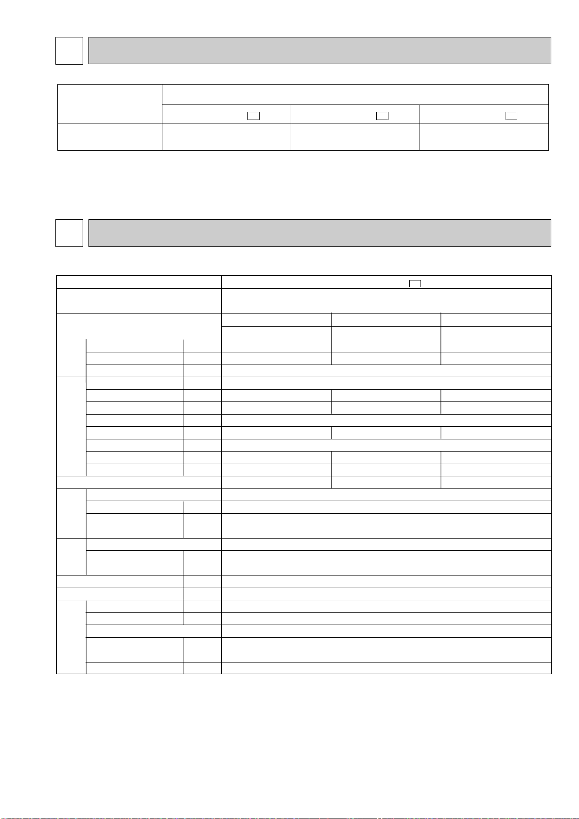
MUX-19TV -
E1
Single phase
230V, 50Hz
Opetate 1 unit
B
2.2
0.8
Hi:2,460 / Lo:1,920
15
3.33
745
—
97.3
45.6
3.00
0.33
2.82
RH220VHAT (Room A) / RH135VHAT (Room B)
1,050 / 650
C-R 2.13/4.18
C-S 3.91/5.76
RA6V60-DA
WHT-BLK 90 BKL-YLW 54
BLK-RED 146
840✕640✕330
63
52
High:730 / Low:580
2
Room A : 0.87
Room B :1.0
520(MS56) / 300(MS56)
Compressor
Electrical
data
Fan
motor
Special
remarks
Capacity
Coefficient of performance(C.O.P)
Outdoor unit power supply
Indoor unit No.
INDOOR / OUTDOOR CORRESPONDENCE TABLE
4
NOTE: Test conditions are based on ISO 5151.
SPECIFICATION
Cooling : Indoor DB27°C / WB19°C
Outdoor DB35°C / WB(24°C)
3
Page 4

Outdoor model
Capacity
Dehumidification
Outdoor air flow
Power outlet
Running current
Power input
Auxiliary heater
Power factor
Starting current
Compressor motor current
Fan motor current
Model
Output
Winding
resistance(at20:)
Model
Winding
resistance(at20:)
Dimensions WOHOD
Weight
Sound level
Fan speed
Fan speed regulator
Refrigerant filling
capacity(R22)
Refrigerating oil (Model)
kW
R/h
K /h
A
A
W
A(kW)
%
A
A
A
W
"
"
mm
kg
dB
rpm
kg
cc
Opetate 1 unit
A
2.5
1.1
3.43
775
98.2
3.10
0.33
3.09
Opetate 1 unit
B or C
2.7
1.2
4.23
965
99.2
3.90
0.33
2.70
Opetate 2 unit
A+B or A+C
2.4+2.7
0.9+1.2
7.56
1,740
99.9
6.99
0.57
2.82
Opetate 3 unit
A+B+C
2.4+1.75✕2
0.9+0.3✕2
7.79
1,785
99.6
7.22
0.57
3.12
MUX-20TV -
E1
Single phase
230V, 50Hz
Opetate 2 unit
B+C
1.75✕2
0.3✕2
High: 2,460 / Low: 1,920
15
4.36
1,000
—
99.7
40
4.03
0.33
3.27
RH140VHAT (Room A) / RH174VHAT (Room B,C)
700/800
C-R 4.03/3.30
C-S 5.71/5.80
RA6V60-DA
WHT-BLK 90 BLK-YLW 54
BLK-RED 146
840✕640✕330
62
52
High: 730 / Low: 580
2
Room A : 0.8
Room B,C : 0.96
300(MS56) / 300(MS56)
Compressor
Electrical
data
Fan
motor
Special
remarks
Capacity
Coefficient of performance(C.O.P)
Outdoor unit power supply
Indoor unit No.
NOTE: Test conditions are based on ISO 5151.
Cooling : Indoor DB27°C / WB19°C
Outdoor DB35°C / WB(24°C)
4
Page 5
Outdoor model
Outdoor unit power supply
Indoor unit No.
Capacity
Dehumidification
Outdoor air flow
Capacity
Power outlet
Running current
Power input
Auxiliary heater
Power factor
Electrical
data
Starting current
Compressor motor current
Fan motor current
kW
R/h
K /h
A
A
W
A(kW)
%
A
A
A
Coefficient of performance(C.O.P)
Model
Output
Winding
Compressor
resistance(at20:)
Model
Winding
Fan
motor
resistance(at20:)
Dimensions WOHOD
Weight
Sound level
Fan speed
W
"
"
mm
kg
dB
rpm
Fan speed regulator
Refrigerant filling
Special
remarks
capacity(R22)
Refrigerating oil (Model)
kg
cc
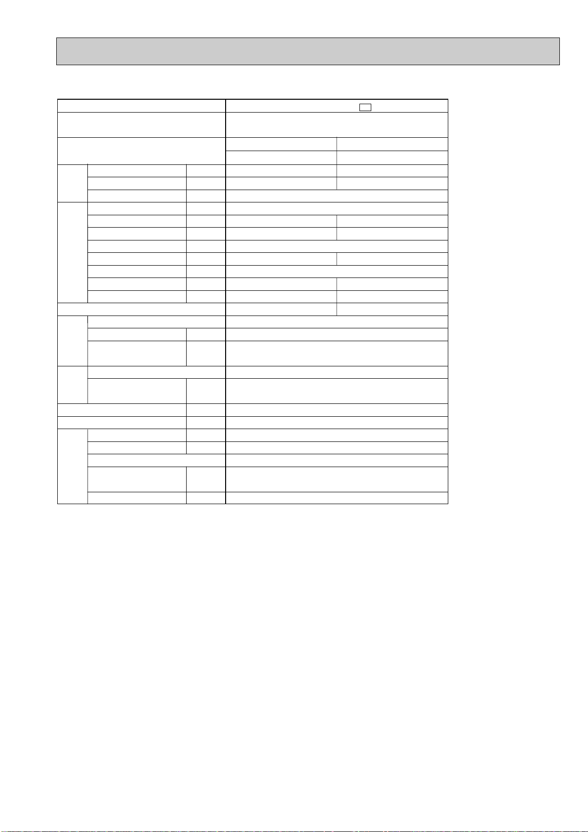
NOTE: Test conditions are based on ISO 5151.
Cooling : Indoor DB27°C / WB19°C
Outdoor DB35°C / WB(24°C)
MUX-25TV -
Single phase
230V, 50Hz
Opetate 1 unit
A or B
3.5
1.6
High:2,760 / Low:1,920
6.11
1,350
96.1
5.79
0.32
2.52
RH231VHAT✕2
1,100✕2
C-R 2.13
C-S 3.91
RA6V60-EA
WHT-BLK 67 BLK-YLW 75
BLK-RED 73
840✕640✕330
High: 810 / Low: 580
Room A: 0.9
Room B: 0.9
520(MS56) / 520(MS56)
25
—
56
65
54
E1
Opetate 2 unit
A+B
3.5✕2
1.6✕2
12.42
2,760
96.6
11.81
0.61
2.46
2
5
Page 6
NOISE CRITERIA CURVES5
90
80
70
60
50
40
30
20
10
63 125 250 500 1000 2000 4000 8000
APPROXIMATE
TERESHOLD OF
HEARING FOR
CONTINUOUS
NOISE
NC-60
NC-50
NC-40
NC-30
NC-20
NC-70
OCTAVE BAND SOUND PRESSURE LEVEL, dB re 0.002 MICRO BAR
BAND CENTER FREQUENCIES, Hz
Test conditions.
Cooling :DB35: WB24:
High
SPEED
52
SPL(dB(A)) LINE
MUX-19TV - E1
MUX-20TV - E1
90
80
70
60
50
40
30
20
10
63 125 250 500 1000 2000 4000 8000
APPROXIMATE
TERESHOLD OF
HEARING FOR
CONTINUOUS
NOISE
NC-60
NC-50
NC-40
NC-30
NC-20
NC-70
OCTAVE BAND SOUND PRESSURE LEVEL, dB re 0.002 MICRO BAR
BAND CENTER FREQUENCIES, Hz
Test conditions.
Cooling :DB35: WB24:
High
SPEED
54
SPL(dB(A)) LINE
MUX-25TV - E1
6
Page 7
6
500
840 61.7
264.2
10°
10°
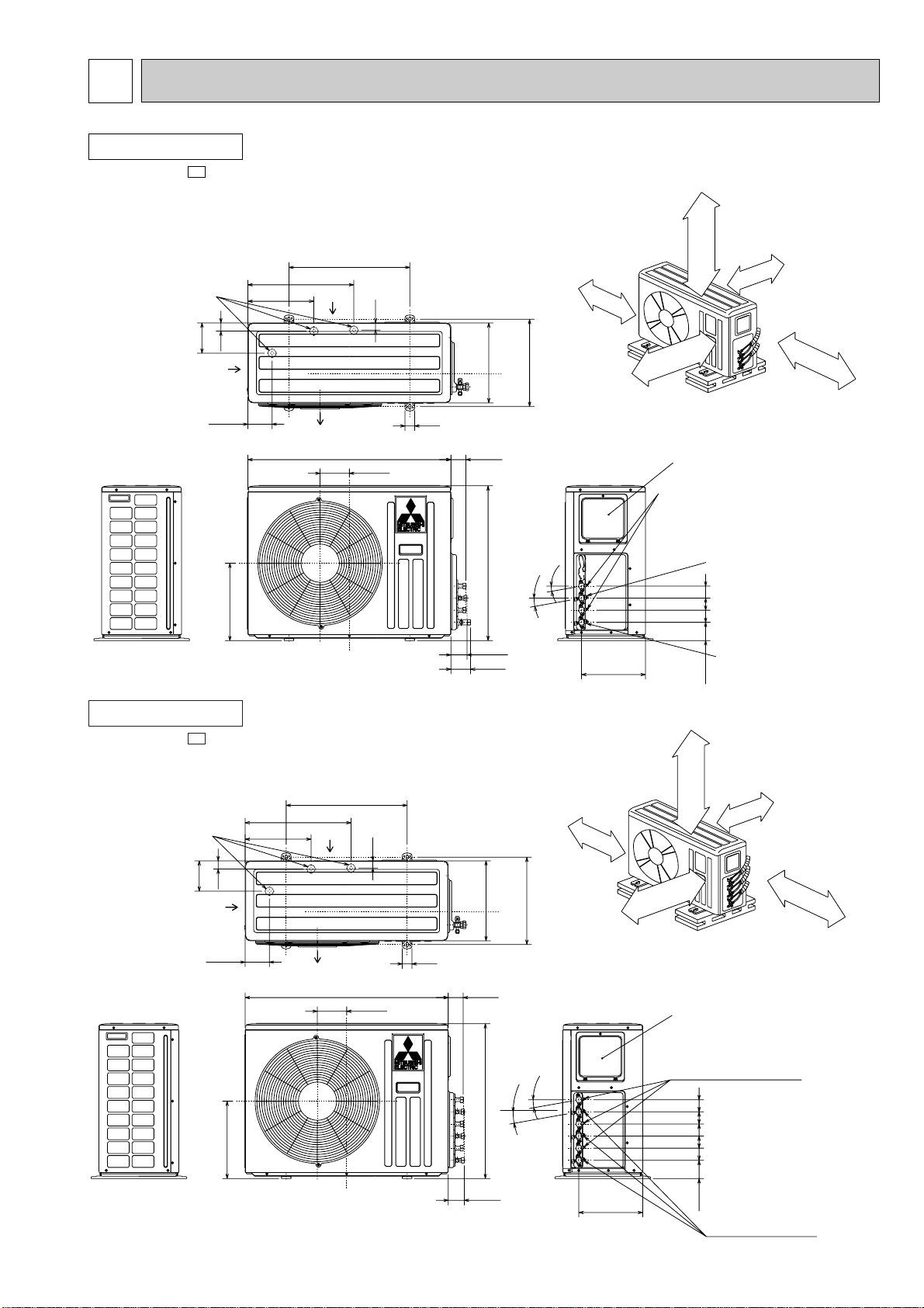
Service panel
Open as a rule
500mm or more if
the front and both
sides are open
100mm or more
200mm or more if
there are obstacles
to both sides
Open as a rule
500mm or more if the back,
both sides and top are open
350mm or more
100mm or more
B UNIT
A UNIT
Gas refrigerant
pipe joint
Refrigerant pipe
(flared) {9.52
Gas refrigerant
pipe joint
Refrigerant pipe
(flared) {12.7
Liquid refrigerant
pipe joint
Refrigerant pipe
(flared) {6.35
66.2
80.7
121.3
40
438.4
Air in
Air out
Air in
272.9
100.3
125.6
319.8
34
330
640
360.6
75.8
505050
Drainage
3hoies {33
}
}
OUTLINES AND DIMENSIONS
OUTDOOR UNIT
MUX-19TV-
E1
Unit: mm
OUTDOOR UNIT
MUX-20TV-
E1
Drainage
3hoies {33
125.6
Air in
34
100.3
319.8
272.9
438.4
Air in
Air out
500
40
840 61.7
121.3
330
640
66.2
7
100mm or more
360.6
Open as a rule
500mm or more if the back,
both sides and top are open
10°
10°
}
}
}
264.2
Service panel
Liquid refrigerant
pipe joint
Refrigerant pipe
(flared) {6.35
C UNIT
B UNIT
A UNIT
5050505050
75.8
Unit: mm
Open as a rule
500mm or more if
the front and both
sides are open
100mm or more
200mm or more if
there are obstacles
to both sides
350mm or more
Gas refrigerant
pipe joint
Refrigerant pipe
(flared) {9.52
Page 8
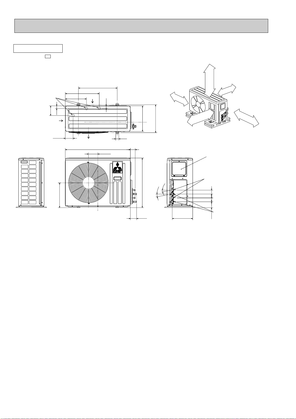
OUTDOOR UNIT
MUX-25TV-
E1
Drainage
3hoies {33
125.6
Air in
34
100.3
319.8
272.9
500
438.4
Air in
Air out
840 61.7
121.3
Unit: mm
Open as a rule
500mm or more if
the front and both
sides are open
100mm or more
100mm or more
330
360.6
Open as a rule
500mm or more if the back,
40
640
both sides and top are open
10°
10°
B UNIT
}
A UNIT
}
Service panel
Liquid refrigerant
pipe joint
Refrigerant pipe
(flared) {6.35
505050
200mm or more if
there are obstacles
to both sides
350mm or more
80.7
264.2
Gas refrigerant
pipe joint
75.8
Refrigerant pipe
(flared) {12.7
8
Page 9
7
1
2
3
123
2
1
3
(3.15A)
RED
RED
NR61
T61
1
2
43
43
C61
LD1
WHT
WHT
OUTDOOR CONTROL PC BOARD
BRN
BLU
BRN
BLU
BRN
X522
X521
BLK
SR862
SR861
LD2
RED
BLK
YLW
WHT
652341
BRN
BLU
BLU
TB4
CN91
CN90
TB2
X521X522
F61
CN73 CN71
TO INDOOR
UNIT B
CONNECTING
12V
PE
CIRCUIT BREAKER
GRN/YLW
ORN
BLU
YLW
BLU
RED
RED
TO INDOOR
UNIT A
CONNECTING
12V
1
2
C2
C1
RC
S
CR
S
MC2
MF61
MC1
BLK
TB1
POWER SUPPLY
~/N
230V
50Hz
1
2
L
N
SYMBOL
C1
C2
C61
F61
MC1
SYMBOL
MC2
MF61
NR61
SR861
SR862
SYMBOL
TB1
TB2~TB4
T61
X521
X522
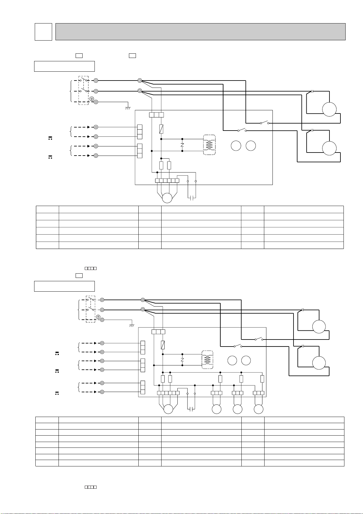
NAME
COMPRESSOR CAPACITOR (MC1)
COMPRESSOR CAPACITOR (MC2)
FAN MOTOR CAPACITOR
FUSE (3.15A)
COMPRESSOR (INNER PROTECTOR)
NAME
COMPRESSOR (INNER PROTECTOR)
FAN MOTOR (INNER PROTECTOR)
SURGE ABSORBER
FAN MOTOR RELAY
FAN MOTOR RELAY
NAME
TERMINAL BLOCK
TERMINAL BLOCK
TRANSFORMER
COMPRESSOR CONTACTOR (MC1)
COMPRESSOR CONTACTOR (MC2)
1
2
3
1
2
3
123
2
1
3
(3.15A)
123123123
RED
RED
21R421R3
NR61
T61
1
2
43
43
C61
LD1
WHT
WHT
OUTDOOR CONTROL PC BOARD
BRN
BLU
BRN
BLU
BRN
BLU
BLU
X522
X521
BLK
SR865
SR866
SR863
SR862
SR861
LD2
RED
BLK
YLW
WHT
652341
BRN
BLU
BLU
TB4
CN86
CN85
CN81
CN91
CN90
TB3
TB2
X521
BLU
BLU
X522
BLU
BLU
21RB
F61
CN74 CN73 CN71
TO INDOOR
UNIT B
CONNECTING
12V
PE
CIRCUIT BREAKER
GRN/YLW
WHT
BLU
ORN
BLU
YLW
BLU
RED
RED
TO INDOOR
UNIT A
CONNECTING
12V
1
2
1
2
C2
C1
RC
S
CR
S
MC2
TO INDOOR
UNIT C
CONNECTING
12V
MF61
MC1
BLK
TB1
POWER SUPPLY
~/N
230V
50Hz
1
2
L
N
SYMBOL
C1
C2
C61
F61
MC1
MC2
MF61
SYMBOL
NR61
SR861
SR862
SR863
SR865
SR866
TB1
SYMBOL
TB2~TB4
T61
X521
X522
21RB
21R3
21R4
NAME
COMPRESSOR CAPACITOR (MC1)
COMPRESSOR CAPACITOR (MC2)
FAN MOTOR CAPACITOR
FUSE (3.15A)
COMPRESSOR (INNER PROTECTOR)
COMPRESSOR (INNER PROTECTOR)
FAN MOTOR (INNER PROTECTOR)
NAME
SURGE ABSORBER
FAN MOTOR RELAY
FAN MOTOR RELAY
RELAY (21RB)
RELAY (C) (21R4)
RELAY (B) (21R3)
TERMINAL BLOCK
NAME
TERMINAL BLOCK
TRANSFORMER
COMPRESSOR CONTACTOR (MC1)
COMPRESSOR CONTACTOR (MC2)
SOLENOID COIL
SOLENOID COIL (B)
SOLENOID COIL (C)
WIRING DIAGRAM
MUX-19TV - MUX-25TV -
OUTDOOR UNIT
MODELS WIRING DIAGRAM
E1E1
NOTE:1. About the outdoor side electric wiring refer to the outdoor unit electric wiring diagram for servicing.
MUX-20TV -
OUTDOOR UNIT
NOTE:1. About the outdoor side electric wiring refer to the outdoor unit electric wiring diagram for servicing.
2. Use copper conductors only. (For field wiring)
3. Symbols below indicate.
/: Terminal block, : Connector
E1
MODEL WIRING DIAGRAM
2. Use copper conductors only. (For field wiring)
3. Symbols below indicate.
/: Terminal block, : Connector
9
VG79B082H01
VG79B081H01
Page 10
8
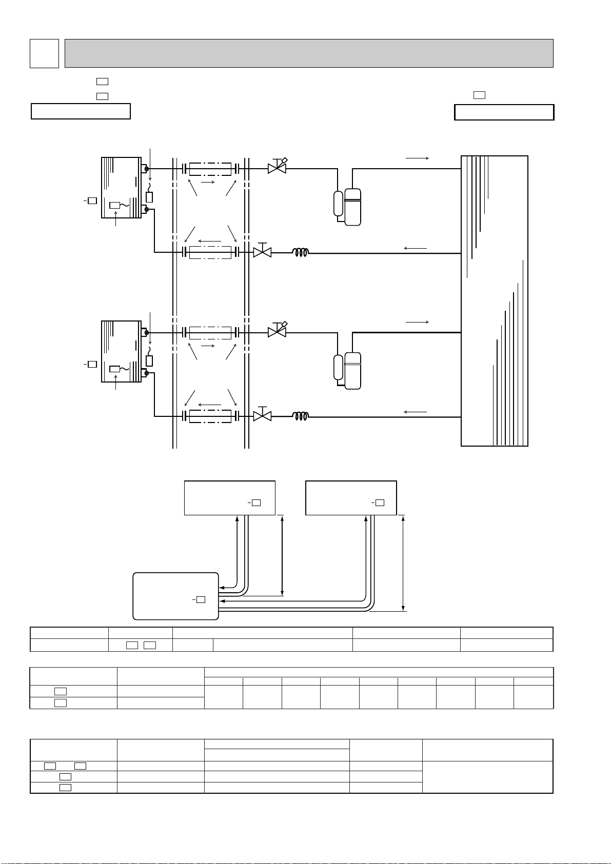
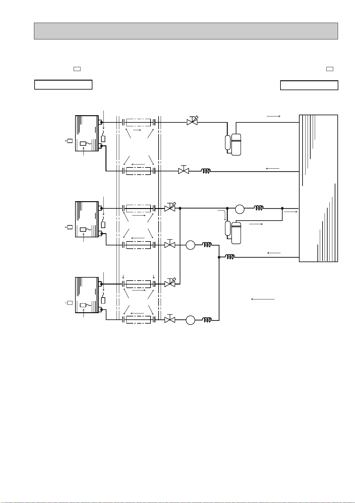
REFRIGERANT SYSTEM DIAGRAM
MSC-07RVMSC-12RV-
INDOOR UNIT
UNIT A
MSC-12RV
MSC-07RV
E3
UNIT B
E3
E3
E3
Indoor
heat
exchanger
Indoor coil
thermistor
RT12
Indoor
heat
exchanger
Room
temperature
thermistor
RT11
Room
temperature
thermistor
RT11
Refrigerant pipe
{12.7
(With insulation)
Flared connection
Refrigerant pipe
{6.35
(With insulation)
Refrigerant pipe
{9.52
(With insulation)
Flared connection
Stop valve
with service port
Stop valve
Capillary tube
{
Stop valve
with service port
3.0 ✕{1.6 ✕ 660
Compressor(MC1)
MUX-19TV-
OUTDOOR UNIT
E1
Outdoor
heat
exchanger
Unit: mm
Indoor coil
thermistor
RT12
Refrigerant pipe
{6.35
(With insulation)
Stop valve
Capillary tube
{
3.0 ✕{1.4 ✕ 810
Compressor(MC2)
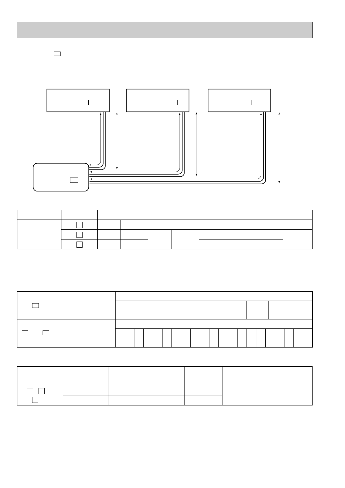
MAX. REFRIGERANT PIPING LENGTH & MAX. HEIGHT DIFFERENCE
Max. limits
MUX-19TV
UNIT No.
,
Outdoor unit
BA
Indoor unit B
MSC-07RV
E1
L
E3
LLHH
Additional piping max. length 15m
Pipe length
15m
Indoor unit A
MSC-12RV
E3
Height difference (H)
10m
ADDITIONAL REFRIGERANT CHARGE (R22:g)
A
B
UNIT
UNIT
Outdoor unit
precharged (g)
870
1,000
7m
0 153045607590105120
8m 9m 10m 11m 12m 13m 14m 15m
Refrigerant piping length (one way)
PIPING PREPARATION
1 Table below shows the specifications of pipes commercially available.
UNIT No. Pipe
BA
and UNIT For liquid 6.35 8 mm
B
UNIT For gas 9.52 8 mm
A
UNIT For gas 12.7 8 mm
2 Ensure that the 2 refrigerant pipes are well insulated to prevent condensation.
3 Refrigerant bending radius must be 10cm or more.
Outside diameter Insulation
mm thickness
10
No. of bends
10
Insulation material
Heat resisting foam plastic
0.045 specific gravity
Page 11
Unit: mm
MSC-09RV-
INDOOR UNIT
UNIT A
MSC-09RV
MSC-09RV
E3
UNIT B
E3
E3
Indoor
heat
exchanger
Indoor coil
thermistor
RT12
Indoor
heat
exchanger
Indoor coil
thermistor
RT12
Room
temperature
thermistor
RT11
Room
temperature
thermistor
RT11
Room
temperature
thermistor
RT11
Refrigerant pipe
{9.52
(With insulation)
Flared connection
Refrigerant pipe
{6.35
(With insulation)
Refrigerant pipe
{9.52
(With insulation)
Flared connection
Refrigerant pipe
{6.35
(With insulation)
Refrigerant pipe
{9.52
Stop valve
with service port
Stop valve
Stop valve
with service port
Stop valve
Solenoid valve
21R3
{
Capillary tube
{
3.0✕{1.4 ✕ 450
Capillary tube
3.0✕{1.6 ✕ 900
Compressor(MC1)
Solenoid valve
21RB
Capillary tube
{
3.0✕{1.6 ✕ 1,000
Compressor(MC2)
Capillary tube
{
3.0✕{1.8 ✕ 450
MUX-20TV-
E1
OUTDOOR UNIT
Outdoor
heat
exchanger
UNIT C
MSC-09RV
E3
Indoor
heat
exchanger
Indoor coil
thermistor
RT12
Flared connection
Refrigerant pipe
{6.35
(With insulation)
Stop valve
with service port
Solenoid valve
21R4
Stop valve
Capillary tube
{
3.0✕{1.6 ✕ 900
Refrigerant flow
11
Page 12
LC
Indoor unit C
MSC-09RV - E3
HL
B HLA
H
Indoor unit B
MSC-09RV - E3
Indoor unit A
MSC-09RV - E3
Outdoor unit
MUX-20TV - E1
MUX-20TV-
7m
0
10m011m1012m2013m3014m4015m5016m6017m7018m8019m9020m
100
21m
110
22m
120
23m
130
24m
140
25m
150
26m
160
27m
170
28m
180
29m
190
30m
200
8m
15
9m
30
10m4511m
60
12m7513m
90
14m
105
15m
120
Refrigerant piping length (one way)
A
unit
Refrigerant piping length (one way, 2 unit total)
Outdoor unit
precharged (g)
800
Outdoor unit
precharged (g)
960
B
unit + C unit
E1
MAX.REFRIGERANT PIPING LENGTH & MAX. HEIGHT DIFFERENCE
Max.
limits
UNIT No.
A
B
C
LA
LB
LC
Pipe length
15m
15m
15m
L
B
+
LC
Total
30m
Height difference (H)
10m
10m
10m
Note: The length of piping to individual units (A,B,C) should not exceed 10 meters.
If units B and C are linked, the maximum combined length of piping should not exceed 15 meters.
ADDITIONAL REFRIGERANT CHARGE (R22:g)
PIPING PREPARATION
1Table below shows the specifications of pipes commercially available.
UNIT No.
BA
, and
C
unit
Pipe
For liquid
For gas
Outside diameter
mm
6.35
9.52
Insulation
thickness
8mm
8mm
No. of bends
10
10
10
Insulation material
Heat resisting foam plastic
0.045 specific gravity
Total
15
2Ensure that the 2 refrigerant pipes are well insulated to prevent condensation.
3Refrigerant bending radius must be 10cm or more.
12
Page 13

MSC-12RV-
E3
MUX-25TV-
E1
Unit: mm
INDOOR UNIT
UNIT A
MSC-12RV
MSC-12RV
E3
UNIT B
E3
Room
temperature
thermistor
RT11
Indoor
heat
exchanger
Indoor coil
thermistor
RT12
Room
temperature
thermistor
RT11
Indoor
heat
exchanger
Indoor coil
thermistor
RT12
Refrigerant pipe
{12.7
(With insulation)
Flared connection
Refrigerant pipe
{6.35
(With insulation)
Refrigerant pipe
{12.7
(With insulation)
Flared connection
Refrigerant pipe
{6.35
(With insulation)
Stop valve
with service port
Stop valve
Capillary tube
{
Stop valve
with service port
Stop valve
Capillary tube
{
Compressor(MC1)
3.0 ✕{1.6 ✕ 550
Compressor(MC2)
3.0 ✕{1.6 ✕ 600
OUTDOOR UNIT
Outdoor
heat
exchanger
MAX. REFRIGERANT PIPING LENGTH & MAX. HEIGHT DIFFERENCE
Max. limits
MUX-25TV
UNIT No.
BA
,
Outdoor unit
MSC-12RV
E1
L
Indoor unit B
E3
LLHH
Additional piping max. length 10m
Pipe length
15m
Indoor unit A
MSC-12RV
E3
Height difference (H)
10m
ADDITIONAL REFRIGERANT CHARGE (R22:g)
A
B
UNIT
UNIT
Outdoor unit
precharged (g)
900
900
7m
0 153045607590105120
8m 9m 10m 11m 12m 13m 14m 15m
Refrigerant piping length (one way)
PIPING PREPARATION
1 Table below shows the specifications of pipes commercially available.
UNIT No. Pipe
BA
and UNIT
For liquid 6.35 8 mm Heat resisting foam plastic
For gas 12.7 8 mm 0.045 specific gravity
2 Ensure that the 2 refrigerant pipes are well insulated to prevent condensation.
3 Refrigerant bending radius must be 10cm or more.
Outside diameter Insulation
mm thickness
13
No. of bends
10
Insulation material
Page 14

9
0.8
0.7
0.6
0.5
0.4
0.3
(kgf/F•G)(MPa•G)
Outdoor low pressure (kgf/F•G)
7
6
5
4
3
8
0.7
0.6
0.5
0.4
0.3
(kgf/F•G)(MPa•G)
Outdoor low pressure (kgf/F•G)
6
5
4
3
7
Outdoor unit current (A)
Outdoor unit current (A)
Single operation (Unit A) Single operation (Unit B)
0.7
0.6
0.5
0.4
0.3
0.2
(kgf/F•G)(MPa•G)
Outdoor low pressure (kgf/F•G)
6
5
4
3
2
7
Outdoor unit current (A)
Single operation (Unit A or B)
7
6
3
4
3
2
7
6
4
5
3
8
4
5
0.8
PERFORMANCE CURVES
MSC-07RV MSC-09RV MSC-12RV -
E3
MUX-19TV -
E3
MUX-20TV -
E3
MUX-25TV -
E1
E1
E1
9-1-1.CAPACITY AND THE INPUT CURVES
(ONE INDOOR UNIT WITH ONE OUTDOOR UNIT)
8.9
11.6
8.2
10.6
7.4
9.6
8.7
6.7
7.8
6.0
6.9
5.4
Indoor air WB temperature
difference (deg.)
MUX-19TV- E1
MUX-19TV- E1
(MSC-12RV- E3 )
(MSC-07RV- E3 )
10.2
9.3
8.5
7.7
6.9
6.1
MUX-20TV- E1
(Single unit A)
(MSC-09RV- E3 )
11.2
10.6
10.2
9.3
8.4
7.5
6.6
MUX-20TV- E1
(MSC-09RV- E3 )
(Single unit B or C)
9.6
8.7
7.8
6.9
MUX-25TV- E1
(MSC-12RV- E3 )
11.6
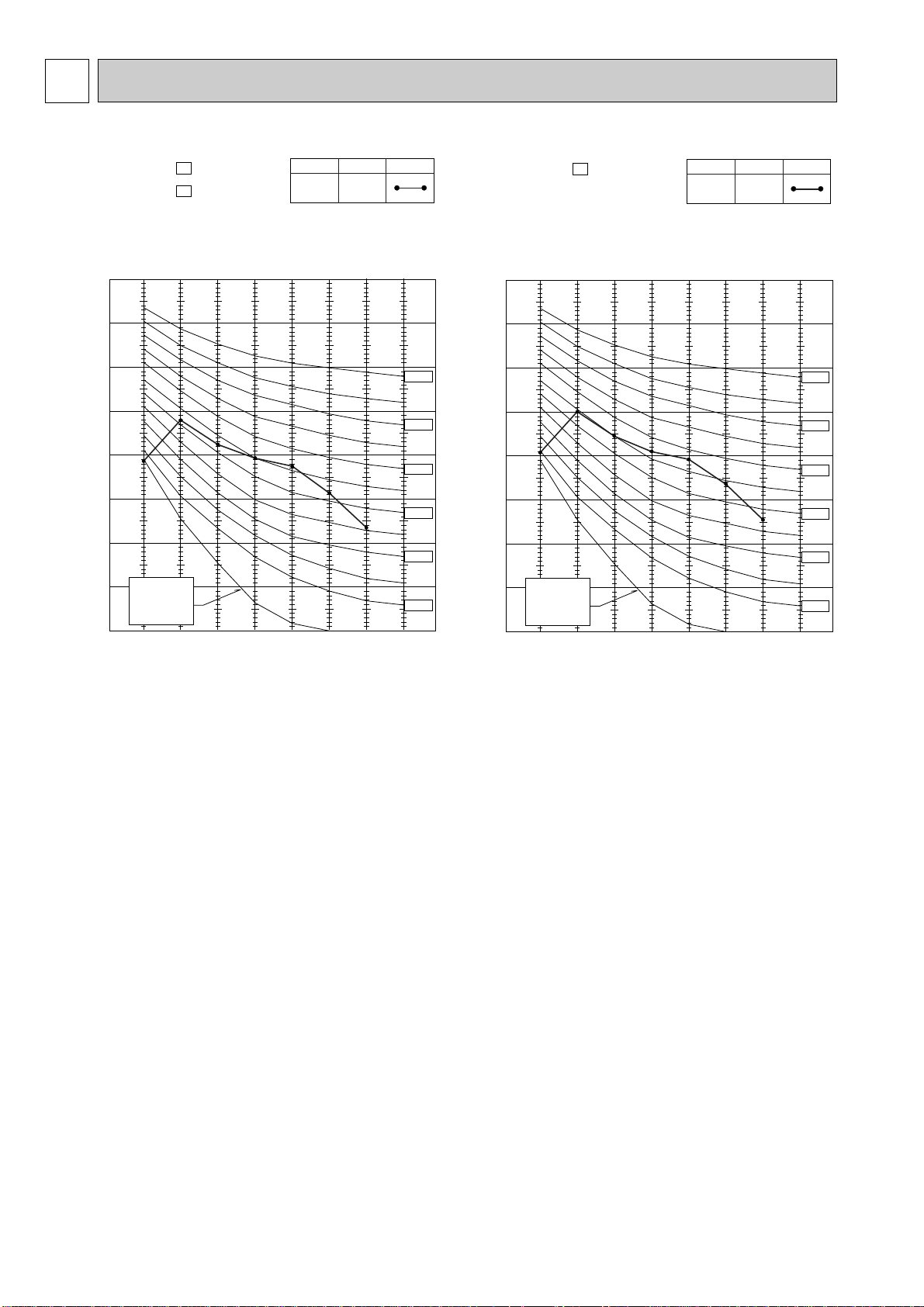
9-1-2.OUTDOOR LOW PRESSURE AND OUTDOOR UNIT CURRENT
COOL operation
① Both indoor and outdoor unit are under same temperature/humidity condition.
Dry-bulb temperature Relative humidity (%)
20
25
30
➁ Air flow should be set at MAX.
MUX-19TV-
E1
50
60
70
MUX-25TV-
E1
14
Page 15

MUX-20TV-
(kgf/F•G)(MPa•G)
Outdoor low pressure (kgf/F•G)
0.8
8
0.7
7
0.6
6
0.5
5
0.4
4
0.3
3
E1
Single operation (Unit A)
4
3
Outdoor unit current (A)
2 2
(kgf/F•G)(MPa•G)
Outdoor low pressure (kgf/F•G)
0.8
8
0.7
7
0.6
6
0.5
5
0.4
4
0.3
3
Single operation (Unit B or C)
6
5
4
3
Outdoor unit current (A)
15
Page 16

PERFORMANCE DATA
INDOOR INDOOR
21 25 27 30
DB(;) WB(;)
Q SHC SHF INPUT Q SHC SHF INPUT Q SHC SHF INPUT Q SHC SHF INPUT
CAPACITY : 2.2 kW INPUT(Total=Indoor+Outdoor) : 780 W SHF : 0.74
OUTDOOR DB(;)
21
21
22
22
22
24
24
24
24
26
26
26
26
26
28
28
28
28
28
30
30
30
30
30
32
32
32
32
32
18
20
18
20
22
18
20
22
24
18
20
22
24
26
18
20
22
24
26
18
20
22
24
26
18
20
22
24
26
2.59
2.70
2.59
2.70
2.81
2.59
2.70
2.81
2.95
2.59
2.70
2.81
2.95
3.04
2.59
2.70
2.81
2.95
3.04
2.59
2.70
2.81
2.95
3.04
2.59
2.70
2.81
2.95
3.04
1.45
1.19
1.55
1.29
1.01
1.76
1.51
1.23
0.94
1.96
1.72
1.46
1.18
0.85
2.17
1.94
1.68
1.42
1.09
2.38
2.16
1.91
1.65
1.34
2.59
2.37
2.13
1.89
1.58
0.56
0.44
0.60
0.48
0.36
0.68
0.56
0.44
0.32
0.76
0.64
0.52
0.40
0.28
0.84
0.72
0.60
0.48
0.36
0.92
0.80
0.68
0.56
0.44
1.00
0.88
0.76
0.64
0.52
624
655
624
655
679
624
655
679
710
624
655
679
710
749
624
655
679
710
749
624
655
679
710
749
624
655
679
710
749
2.48
2.59
2.48
2.59
2.71
2.48
2.59
2.71
2.84
2.48
2.59
2.71
2.84
2.95
2.48
2.59
2.71
2.84
2.95
2.48
2.59
2.71
2.84
2.95
2.48
2.59
2.71
2.84
2.95
1.39
1.14
1.49
1.24
0.97
1.68
1.45
1.19
0.91
1.88
1.65
1.41
1.14
0.83
2.08
1.86
1.62
1.36
1.06
2.28
2.07
1.84
1.59
1.30
2.48
2.27
2.06
1.82
1.53
0.56
0.44
0.60
0.48
0.36
0.68
0.56
0.44
0.32
0.76
0.64
0.52
0.40
0.28
0.84
0.72
0.60
0.48
0.36
0.92
0.80
0.68
0.56
0.44
1.00
0.88
0.76
0.64
0.52
655
694
655
694
722
655
694
722
749
655
694
722
749
788
655
694
722
749
788
655
694
722
749
788
655
694
722
749
788
2.38
2.51
2.38
2.51
2.64
2.38
2.51
2.64
2.77
2.38
2.51
2.64
2.77
2.90
2.38
2.51
2.64
2.77
2.90
2.38
2.51
2.64
2.77
2.90
2.38
2.51
2.64
2.77
2.90
1.33
1.10
1.43
1.20
0.95
1.62
1.40
1.16
0.89
1.81
1.61
1.37
1.11
0.81
2.00
1.81
1.58
1.33
1.05
2.19
2.01
1.80
1.55
1.28
2.38
2.21
2.01
1.77
1.51
0.56
0.44
0.60
0.48
0.36
0.68
0.56
0.44
0.32
0.76
0.64
0.52
0.40
0.28
0.84
0.72
0.60
0.48
0.36
0.92
0.80
0.68
0.56
0.44
1.00
0.88
0.76
0.64
0.52
686
710
686
710
741
686
710
741
772
686
710
741
772
811
686
710
741
772
811
686
710
741
772
811
686
710
741
772
811
2.29
2.42
2.29
2.42
2.53
2.29
2.42
2.53
2.68
2.29
2.42
2.53
2.68
2.82
2.29
2.42
2.53
2.68
2.82
2.29
2.42
2.53
2.68
2.82
2.29
2.42
2.53
2.68
2.82
1.28
1.06
1.37
1.16
0.91
1.56
1.36
1.11
0.86
1.74
1.55
1.32
1.07
0.79
1.92
1.74
1.52
1.29
1.01
2.10
1.94
1.72
1.50
1.24
2.29
2.13
1.92
1.72
1.46
0.56
0.44
0.60
0.48
0.36
0.68
0.56
0.44
0.32
0.76
0.64
0.52
0.40
0.28
0.84
0.72
0.60
0.48
0.36
0.92
0.80
0.68
0.56
0.44
1.00
0.88
0.76
0.64
0.52
718
741
718
741
772
718
741
772
811
718
741
772
811
835
718
741
772
811
835
718
741
772
811
835
718
741
772
811
835
COOL operation (230V)
MSC-07RV - (Single) : MUX-19TV -
E1E3
NOTE Q :Total capacity (kW) SHF :Sensible heat factor
SHC :Sensible heat capacity (kW) INPUT :Total power input (W)
16
Page 17

PERFORMANCE DATA
INDOOR INDOOR
35 40 46
DB(;) WB(;)
Q SHC SHF INPUT Q SHC SHF INPUT Q SHC SHF INPUT
CAPACITY : 2.2 kW INPUT(Total=Indoor+Outdoor) : 780 W SHF : 0.74
OUTDOOR DB(;)
21
21
22
22
22
24
24
24
24
26
26
26
26
26
28
28
28
28
28
30
30
30
30
30
32
32
32
32
32
18
20
18
20
22
18
20
22
24
18
20
22
24
26
18
20
22
24
26
18
20
22
24
26
18
20
22
24
26
2.16
2.27
2.16
2.27
2.40
2.16
2.27
2.40
2.53
2.16
2.27
2.40
2.53
2.66
2.16
2.27
2.40
2.53
2.66
2.16
2.27
2.40
2.53
2.66
2.16
2.27
2.40
2.53
2.66
1.21
1.00
1.29
1.09
0.86
1.47
1.27
1.06
0.81
1.64
1.45
1.25
1.01
0.75
1.81
1.63
1.44
1.21
0.96
1.98
1.81
1.63
1.42
1.17
2.16
1.99
1.82
1.62
1.38
0.56
0.44
0.60
0.48
0.36
0.68
0.56
0.44
0.32
0.76
0.64
0.52
0.40
0.28
0.84
0.72
0.60
0.48
0.36
0.92
0.80
0.68
0.56
0.44
1.00
0.88
0.76
0.64
0.52
764
796
764
796
827
764
796
827
858
764
796
827
858
889
764
796
827
858
889
764
796
827
858
889
764
796
827
858
889
1.98
2.11
1.98
2.11
2.24
1.98
2.11
2.24
2.38
1.98
2.11
2.24
2.38
2.51
1.98
2.11
2.24
2.38
2.51
1.98
2.11
2.24
2.38
2.51
1.98
2.11
2.24
2.38
2.51
1.11
0.93
1.19
1.01
0.81
1.35
1.18
0.99
0.76
1.50
1.35
1.17
0.95
0.70
1.66
1.52
1.35
1.14
0.90
1.82
1.69
1.53
1.33
1.10
1.98
1.86
1.71
1.52
1.30
0.56
0.44
0.60
0.48
0.36
0.68
0.56
0.44
0.32
0.76
0.64
0.52
0.40
0.28
0.84
0.72
0.60
0.48
0.36
0.92
0.80
0.68
0.56
0.44
1.00
0.88
0.76
0.64
0.52
811
835
811
835
874
811
835
874
897
811
835
874
897
928
811
835
874
897
928
811
835
874
897
928
811
835
874
897
928
1.83
1.96
1.83
1.96
2.09
1.83
1.96
2.09
2.24
1.83
1.96
2.09
2.24
2.35
1.83
1.96
2.09
2.24
2.35
1.83
1.96
2.09
2.24
2.35
1.83
1.96
2.09
2.24
2.35
1.02
0.86
1.10
0.94
0.75
1.24
1.10
0.92
0.72
1.39
1.25
1.09
0.90
0.66
1.53
1.41
1.25
1.08
0.85
1.68
1.57
1.42
1.26
1.04
1.83
1.72
1.59
1.44
1.22
0.56
0.44
0.60
0.48
0.36
0.68
0.56
0.44
0.32
0.76
0.64
0.52
0.40
0.28
0.84
0.72
0.60
0.48
0.36
0.92
0.80
0.68
0.56
0.44
1.00
0.88
0.76
0.64
0.52
842
881
842
881
905
842
881
905
936
842
881
905
936
967
842
881
905
936
967
842
881
905
936
967
842
881
905
936
967
COOL operation (230V)
MSC-07RV - (Single) : MUX-19TV -
E1E3
NOTE Q :Total capacity (kW) SHF :Sensible heat factor
SHC :Sensible heat capacity (kW) INPUT :Total power input (W)
17
Page 18

PERFORMANCE DATA
INDOOR INDOOR
21 25 27 30
DB(;) WB(;)
Q SHC SHF INPUT Q SHC SHF INPUT Q SHC SHF INPUT Q SHC SHF INPUT
CAPACITY : 3.5 kW INPUT(Total=Indoor+Outdoor) : 1320W SHF : 0.67
OUTDOOR DB(;)
21
21
22
22
22
24
24
24
24
26
26
26
26
26
28
28
28
28
28
30
30
30
30
30
32
32
32
32
32
18
20
18
20
22
18
20
22
24
18
20
22
24
26
18
20
22
24
26
18
20
22
24
26
18
20
22
24
26
4.11
4.29
4.11
4.29
4.46
4.11
4.29
4.46
4.69
4.11
4.29
4.46
4.69
4.83
4.11
4.29
4.46
4.69
4.83
4.11
4.29
4.46
4.69
4.83
4.11
4.29
4.46
4.69
4.83
2.02
1.59
2.18
1.76
1.29
2.51
2.10
1.65
1.17
2.84
2.44
2.01
1.55
1.01
3.17
2.79
2.37
1.92
1.40
3.50
3.13
2.72
2.30
1.79
3.82
3.47
3.08
2.67
2.17
0.49
0.37
0.53
0.41
0.29
0.61
0.49
0.37
0.25
0.69
0.57
0.45
0.33
0.21
0.77
0.65
0.53
0.41
0.29
0.85
0.73
0.61
0.49
0.37
0.93
0.81
0.69
0.57
0.45
0.49
0.37
0.53
0.41
0.29
0.61
0.49
0.37
0.25
0.69
0.57
0.45
0.33
0.21
0.77
0.65
0.53
0.41
0.29
0.85
0.73
0.61
0.49
0.37
0.93
0.81
0.69
0.57
0.45
0.49
0.37
0.53
0.41
0.29
0.61
0.49
0.37
0.25
0.69
0.57
0.45
0.33
0.21
0.77
0.65
0.53
0.41
0.29
0.85
0.73
0.61
0.49
0.37
0.93
0.81
0.69
0.57
0.45
0.49
0.37
0.53
0.41
0.29
0.61
0.49
0.37
0.25
0.69
0.57
0.45
0.33
0.21
0.77
0.65
0.53
0.41
0.29
0.85
0.73
0.61
0.49
0.37
0.93
0.81
0.69
0.57
0.45
1056
1109
1056
1109
1148
1056
1109
1148
1201
1056
1109
1148
1201
1267
1056
1109
1148
1201
1267
1056
1109
1148
1201
1267
1056
1109
1148
1201
1267
3.94
4.11
3.94
4.11
4.31
3.94
4.11
4.31
4.52
3.94
4.11
4.31
4.52
4.69
3.94
4.11
4.31
4.52
4.69
3.94
4.11
4.31
4.52
4.69
3.94
4.11
4.31
4.52
4.69
1.93
1.52
2.09
1.69
1.25
2.40
2.02
1.59
1.13
2.72
2.34
1.94
1.49
0.98
3.03
2.67
2.28
1.85
1.36
3.35
3.00
2.63
2.21
1.74
3.66
3.33
2.97
2.57
2.11
1109
1175
1109
1175
1221
1109
1175
1221
1267
1109
1175
1221
1267
1333
1109
1175
1221
1267
1333
1109
1175
1221
1267
1333
1109
1175
1221
1267
1333
3.78
3.99
3.78
3.99
4.20
3.78
3.99
4.20
4.41
3.78
3.99
4.20
4.41
4.62
3.78
3.99
4.20
4.41
4.62
3.78
3.99
4.20
4.41
4.62
3.78
3.99
4.20
4.41
4.62
1.85
1.48
2.00
1.64
1.22
2.31
1.96
1.55
1.10
2.61
2.27
1.89
1.46
0.97
2.91
2.59
2.23
1.81
1.34
3.21
2.91
2.56
2.16
1.71
3.52
3.23
2.90
2.51
2.08
1162
1201
1162
1201
1254
1162
1201
1254
1307
1162
1201
1254
1307
1373
1162
1201
1254
1307
1373
1162
1201
1254
1307
1373
1162
1201
1254
1307
1373
3.64
3.85
3.64
3.85
4.03
3.64
3.85
4.03
4.27
3.64
3.85
4.03
4.27
4.48
3.64
3.85
4.03
4.27
4.48
3.64
3.85
4.03
4.27
4.48
3.64
3.85
4.03
4.27
4.48
1.78
1.42
1.93
1.58
1.17
2.22
1.89
1.49
1.07
2.51
2.19
1.81
1.41
0.94
2.80
2.50
2.13
1.75
1.30
3.09
2.81
2.46
2.09
1.66
3.39
3.12
2.78
2.43
2.02
1214
1254
1214
1254
1307
1214
1254
1307
1373
1214
1254
1307
1373
1412
1214
1254
1307
1373
1412
1214
1254
1307
1373
1412
1214
1254
1307
1373
1412
COOL operation (230V)
MSC-12RV - (Single) : MUX-19TV -
E1E3
NOTE Q :Total capacity (kW) SHF :Sensible heat factor
SHC :Sensible heat capacity (kW) INPUT :Total power input (W)
18
Page 19

PERFORMANCE DATA
INDOOR INDOOR
35 40 46
DB(;) WB(;)
Q SHC SHF INPUT Q SHC SHF INPUT Q SHC SHF INPUT
CAPACITY : 3.5 kW INPUT(Total=Indoor+Outdoor) : 1320W SHF : 0.67
OUTDOOR DB(;)
21
21
22
22
22
24
24
24
24
26
26
26
26
26
28
28
28
28
28
30
30
30
30
30
32
32
32
32
32
18
20
18
20
22
18
20
22
24
18
20
22
24
26
18
20
22
24
26
18
20
22
24
26
18
20
22
24
26
3.43
3.61
3.43
3.61
3.82
3.43
3.61
3.82
4.03
3.43
3.61
3.82
4.03
4.24
3.43
3.61
3.82
4.03
4.24
3.43
3.61
3.82
4.03
4.24
3.43
3.61
3.82
4.03
4.24
1.68
1.33
1.82
1.48
1.11
2.09
1.77
1.41
1.01
2.37
2.05
1.72
1.33
0.89
2.64
2.34
2.02
1.65
1.23
2.92
2.63
2.33
1.97
1.57
3.19
2.92
2.63
2.29
1.91
0.49
0.37
0.53
0.41
0.29
0.61
0.49
0.37
0.25
0.69
0.57
0.45
0.33
0.21
0.77
0.65
0.53
0.41
0.29
0.85
0.73
0.61
0.49
0.37
0.93
0.81
0.69
0.57
0.45
0.49
0.37
0.53
0.41
0.29
0.61
0.49
0.37
0.25
0.69
0.57
0.45
0.33
0.21
0.77
0.65
0.53
0.41
0.29
0.85
0.73
0.61
0.49
0.37
0.93
0.81
0.69
0.57
0.45
0.49
0.37
0.53
0.41
0.29
0.61
0.49
0.37
0.25
0.69
0.57
0.45
0.33
0.21
0.77
0.65
0.53
0.41
0.29
0.85
0.73
0.61
0.49
0.37
0.93
0.81
0.69
0.57
0.45
1294
1346
1294
1346
1399
1294
1346
1399
1452
1294
1346
1399
1452
1505
1294
1346
1399
1452
1505
1294
1346
1399
1452
1505
1294
1346
1399
1452
1505
3.15
3.36
3.15
3.36
3.57
3.15
3.36
3.57
3.78
3.15
3.36
3.57
3.78
3.99
3.15
3.36
3.57
3.78
3.99
3.15
3.36
3.57
3.78
3.99
3.15
3.36
3.57
3.78
3.99
1.54
1.24
1.67
1.38
1.04
1.92
1.65
1.32
0.95
2.17
1.92
1.61
1.25
0.84
2.43
2.18
1.89
1.55
1.16
2.68
2.45
2.18
1.85
1.48
2.93
2.72
2.46
2.15
1.80
1373
1412
1373
1412
1478
1373
1412
1478
1518
1373
1412
1478
1518
1571
1373
1412
1478
1518
1571
1373
1412
1478
1518
1571
1373
1412
1478
1518
1571
2.91
3.12
2.91
3.12
3.33
2.91
3.12
3.33
3.57
2.91
3.12
3.33
3.57
3.75
2.91
3.12
3.33
3.57
3.75
2.91
3.12
3.33
3.57
3.75
2.91
3.12
3.33
3.57
3.75
1.42
1.15
1.54
1.28
0.96
1.77
1.53
1.23
0.89
2.00
1.78
1.50
1.18
0.79
2.24
2.02
1.76
1.46
1.09
2.47
2.27
2.03
1.75
1.39
2.70
2.52
2.29
2.03
1.69
1426
1492
1426
1492
1531
1426
1492
1531
1584
1426
1492
1531
1584
1637
1426
1492
1531
1584
1637
1426
1492
1531
1584
1637
1426
1492
1531
1584
1637
COOL operation (230V)
MSC-12RV - (Single) : MUX-19TV -
E1E3
NOTE Q :Total capacity (kW) SHF :Sensible heat factor
SHC :Sensible heat capacity (kW) INPUT :Total power input (W)
19
Page 20

PERFORMANCE DATA
INDOOR INDOOR
21 25 27 30
DB(;) WB(;)
Q SHC SHF INPUT Q SHC SHF INPUT Q SHC SHF INPUT Q SHC SHF INPUT
CAPACITY : 2.5 kW INPUT(Total=Indoor+Outdoor) : 810W SHF : 0.70
OUTDOOR DB(;)
21
21
22
22
22
24
24
24
24
26
26
26
26
26
28
28
28
28
28
30
30
30
30
30
32
32
32
32
32
18
20
18
20
22
18
20
22
24
18
20
22
24
26
18
20
22
24
26
18
20
22
24
26
18
20
22
24
26
2.94
3.06
2.94
3.06
3.19
2.94
3.06
3.19
3.35
2.94
3.06
3.19
3.35
3.45
2.94
3.06
3.19
3.35
3.45
2.94
3.06
3.19
3.35
3.45
2.94
3.06
3.19
3.35
3.45
1.53
1.23
1.65
1.35
1.02
1.88
1.59
1.28
0.94
2.12
1.84
1.53
1.21
0.83
2.35
2.08
1.79
1.47
1.10
2.59
2.33
2.04
1.74
1.38
2.82
2.57
2.30
2.01
1.66
0.52
0.40
0.56
0.44
0.32
0.64
0.52
0.40
0.28
0.72
0.60
0.48
0.36
0.24
0.80
0.68
0.56
0.44
0.32
0.88
0.76
0.64
0.52
0.40
0.96
0.84
0.72
0.60
0.48
0.52
0.40
0.56
0.44
0.32
0.64
0.52
0.40
0.28
0.72
0.60
0.48
0.36
0.24
0.80
0.68
0.56
0.44
0.32
0.88
0.76
0.64
0.52
0.40
0.96
0.84
0.72
0.60
0.48
0.52
0.40
0.56
0.44
0.32
0.64
0.52
0.40
0.28
0.72
0.60
0.48
0.36
0.24
0.80
0.68
0.56
0.44
0.32
0.88
0.76
0.64
0.52
0.40
0.96
0.84
0.72
0.60
0.48
0.52
0.40
0.56
0.44
0.32
0.64
0.52
0.40
0.28
0.72
0.60
0.48
0.36
0.24
0.80
0.68
0.56
0.44
0.32
0.88
0.76
0.64
0.52
0.40
0.96
0.84
0.72
0.60
0.48
648
680
648
680
705
648
680
705
737
648
680
705
737
778
648
680
705
737
778
648
680
705
737
778
648
680
705
737
778
2.81
2.94
2.81
2.94
3.08
2.81
2.94
3.08
3.23
2.81
2.94
3.08
3.23
3.35
2.81
2.94
3.08
3.23
3.35
2.81
2.94
3.08
3.23
3.35
2.81
2.94
3.08
3.23
3.35
1.46
1.18
1.58
1.29
0.98
1.80
1.53
1.23
0.90
2.03
1.76
1.48
1.16
0.80
2.25
2.00
1.72
1.42
1.07
2.48
2.23
1.97
1.68
1.34
2.70
2.47
2.21
1.94
1.61
680
721
680
721
749
680
721
749
778
680
721
749
778
818
680
721
749
778
818
680
721
749
778
818
680
721
749
778
818
2.70
2.85
2.70
2.85
3.00
2.70
2.85
3.00
3.15
2.70
2.85
3.00
3.15
3.30
2.70
2.85
3.00
3.15
3.30
2.70
2.85
3.00
3.15
3.30
2.70
2.85
3.00
3.15
3.30
1.40
1.14
1.51
1.25
0.96
1.73
1.48
1.20
0.88
1.94
1.71
1.44
1.13
0.79
2.16
1.94
1.68
1.39
1.06
2.38
2.17
1.92
1.64
1.32
2.59
2.39
2.16
1.89
1.58
713
737
713
737
770
713
737
770
802
713
737
770
802
842
713
737
770
802
842
713
737
770
802
842
713
737
770
802
842
2.60
2.75
2.60
2.75
2.88
2.60
2.75
2.88
3.05
2.60
2.75
2.88
3.05
3.20
2.60
2.75
2.88
3.05
3.20
2.60
2.75
2.88
3.05
3.20
2.60
2.75
2.88
3.05
3.20
1.35
1.10
1.46
1.21
0.92
1.66
1.43
1.15
0.85
1.87
1.65
1.38
1.10
0.77
2.08
1.87
1.61
1.34
1.02
2.29
2.09
1.84
1.59
1.28
2.50
2.31
2.07
1.83
1.54
745
770
745
770
802
745
770
802
842
745
770
802
842
867
745
770
802
842
867
745
770
802
842
867
745
770
802
842
867
COOL operation (230V)
MSC-09RV - (Single Room A) : MUX-20TV -
E1E3
NOTE Q :Total capacity (kW) SHF :Sensible heat factor
SHC :Sensible heat capacity (kW) INPUT :Total power input (W)
20
Page 21

PERFORMANCE DATA
INDOOR INDOOR
35 40 46
DB(;) WB(;)
Q SHC SHF INPUT Q SHC SHF INPUT Q SHC SHF INPUT
CAPACITY : 2.5 kW INPUT(Total=Indoor+Outdoor) : 810W SHF : 0.70
OUTDOOR DB(;)
21
21
22
22
22
24
24
24
24
26
26
26
26
26
28
28
28
28
28
30
30
30
30
30
32
32
32
32
32
18
20
18
20
22
18
20
22
24
18
20
22
24
26
18
20
22
24
26
18
20
22
24
26
18
20
22
24
26
2.45
2.58
2.45
2.58
2.73
2.45
2.58
2.73
2.88
2.45
2.58
2.73
2.88
3.03
2.45
2.58
2.73
2.88
3.03
2.45
2.58
2.73
2.88
3.03
2.45
2.58
2.73
2.88
3.03
1.27
1.03
1.37
1.13
0.87
1.57
1.34
1.09
0.81
1.76
1.55
1.31
1.04
0.73
1.96
1.75
1.53
1.27
0.97
2.16
1.96
1.74
1.50
1.21
2.35
2.16
1.96
1.73
1.45
0.52
0.40
0.56
0.44
0.32
0.64
0.52
0.40
0.28
0.72
0.60
0.48
0.36
0.24
0.80
0.68
0.56
0.44
0.32
0.88
0.76
0.64
0.52
0.40
0.96
0.84
0.72
0.60
0.48
0.52
0.40
0.56
0.44
0.32
0.64
0.52
0.40
0.28
0.72
0.60
0.48
0.36
0.24
0.80
0.68
0.56
0.44
0.32
0.88
0.76
0.64
0.52
0.40
0.96
0.84
0.72
0.60
0.48
0.52
0.40
0.56
0.44
0.32
0.64
0.52
0.40
0.28
0.72
0.60
0.48
0.36
0.24
0.80
0.68
0.56
0.44
0.32
0.88
0.76
0.64
0.52
0.40
0.96
0.84
0.72
0.60
0.48
794
826
794
826
859
794
826
859
891
794
826
859
891
923
794
826
859
891
923
794
826
859
891
923
794
826
859
891
923
2.25
2.40
2.25
2.40
2.55
2.25
2.40
2.55
2.70
2.25
2.40
2.55
2.70
2.85
2.25
2.40
2.55
2.70
2.85
2.25
2.40
2.55
2.70
2.85
2.25
2.40
2.55
2.70
2.85
1.17
0.96
1.26
1.06
0.82
1.44
1.25
1.02
0.76
1.62
1.44
1.22
0.97
0.68
1.80
1.63
1.43
1.19
0.91
1.98
1.82
1.63
1.40
1.14
2.16
2.02
1.84
1.62
1.37
842
867
842
867
907
842
867
907
932
842
867
907
932
964
842
867
907
932
964
842
867
907
932
964
842
867
907
932
964
2.08
2.23
2.08
2.23
2.38
2.08
2.23
2.38
2.55
2.08
2.23
2.38
2.55
2.68
2.08
2.23
2.38
2.55
2.68
2.08
2.23
2.38
2.55
2.68
2.08
2.23
2.38
2.55
2.68
1.08
0.89
1.16
0.98
0.76
1.33
1.16
0.95
0.71
1.49
1.34
1.14
0.92
0.64
1.66
1.51
1.33
1.12
0.86
1.83
1.69
1.52
1.33
1.07
1.99
1.87
1.71
1.53
1.28
875
915
875
915
940
875
915
940
972
875
915
940
972
1004
875
915
940
972
1004
875
915
940
972
1004
875
915
940
972
1004
COOL operation (230V)
MSC-09RV - (Single Room A) : MUX-20TV -
E1E3
NOTE Q :Total capacity (kW) SHF :Sensible heat factor
SHC :Sensible heat capacity (kW) INPUT :Total power input (W)
21
Page 22

PERFORMANCE DATA
INDOOR INDOOR
21 25 27 30
DB(;) WB(;)
Q SHC SHF INPUT Q SHC SHF INPUT Q SHC SHF INPUT Q SHC SHF INPUT
CAPACITY : 2.7 kW INPUT(Total=Indoor+Outdoor) : 1000W SHF : 0.69
OUTDOOR DB(;)
21
21
22
22
22
24
24
24
24
26
26
26
26
26
28
28
28
28
28
30
30
30
30
30
32
32
32
32
32
18
20
18
20
22
18
20
22
24
18
20
22
24
26
18
20
22
24
26
18
20
22
24
26
18
20
22
24
26
3.17
3.31
3.17
3.31
3.44
3.17
3.31
3.44
3.62
3.17
3.31
3.44
3.62
3.73
3.17
3.31
3.44
3.62
3.73
3.17
3.31
3.44
3.62
3.73
3.17
3.31
3.44
3.62
3.73
1.62
1.29
1.74
1.42
1.07
2.00
1.69
1.34
0.98
2.25
1.95
1.62
1.27
0.86
2.51
2.22
1.89
1.56
1.16
2.76
2.48
2.17
1.85
1.45
3.01
2.75
2.44
2.13
1.75
0.51
0.39
0.55
0.43
0.31
0.63
0.51
0.39
0.27
0.71
0.59
0.47
0.35
0.23
0.79
0.67
0.55
0.43
0.31
0.87
0.75
0.63
0.51
0.39
0.95
0.83
0.71
0.59
0.47
0.51
0.39
0.55
0.43
0.31
0.63
0.51
0.39
0.27
0.71
0.59
0.47
0.35
0.23
0.79
0.67
0.55
0.43
0.31
0.87
0.75
0.63
0.51
0.39
0.95
0.83
0.71
0.59
0.47
0.51
0.39
0.55
0.43
0.31
0.63
0.51
0.39
0.27
0.71
0.59
0.47
0.35
0.23
0.79
0.67
0.55
0.43
0.31
0.87
0.75
0.63
0.51
0.39
0.95
0.83
0.71
0.59
0.47
0.51
0.39
0.55
0.43
0.31
0.63
0.51
0.39
0.27
0.71
0.59
0.47
0.35
0.23
0.79
0.67
0.55
0.43
0.31
0.87
0.75
0.63
0.51
0.39
0.95
0.83
0.71
0.59
0.47
800
840
800
840
870
800
840
870
910
800
840
870
910
960
800
840
870
910
960
800
840
870
910
960
800
840
870
910
960
3.04
3.17
3.04
3.17
3.32
3.04
3.17
3.32
3.48
3.04
3.17
3.32
3.48
3.62
3.04
3.17
3.32
3.48
3.62
3.04
3.17
3.32
3.48
3.62
3.04
3.17
3.32
3.48
3.62
1.55
1.24
1.67
1.36
1.03
1.91
1.62
1.30
0.94
2.16
1.87
1.56
1.22
0.83
2.40
2.13
1.83
1.50
1.12
2.64
2.38
2.09
1.78
1.41
2.89
2.63
2.36
2.05
1.70
840
890
840
890
925
840
890
925
960
840
890
925
960
1010
840
890
925
960
1010
840
890
925
960
1010
840
890
925
960
1010
2.92
3.08
2.92
3.08
3.24
2.92
3.08
3.24
3.40
2.92
3.08
3.24
3.40
3.56
2.92
3.08
3.24
3.40
3.56
2.92
3.08
3.24
3.40
3.56
2.92
3.08
3.24
3.40
3.56
1.49
1.20
1.60
1.32
1.00
1.84
1.57
1.26
0.92
2.07
1.82
1.52
1.19
0.82
2.30
2.06
1.78
1.46
1.10
2.54
2.31
2.04
1.74
1.39
2.77
2.55
2.30
2.01
1.68
880
910
880
910
950
880
910
950
990
880
910
950
990
1040
880
910
950
990
1040
880
910
950
990
1040
880
910
950
990
1040
2.81
2.97
2.81
2.97
3.11
2.81
2.97
3.11
3.29
2.81
2.97
3.11
3.29
3.46
2.81
2.97
3.11
3.29
3.46
2.81
2.97
3.11
3.29
3.46
2.81
2.97
3.11
3.29
3.46
1.43
1.16
1.54
1.28
0.96
1.77
1.51
1.21
0.89
1.99
1.75
1.46
1.15
0.79
2.22
1.99
1.71
1.42
1.07
2.44
2.23
1.96
1.68
1.35
2.67
2.47
2.20
1.94
1.62
920
950
920
950
990
920
950
990
1040
920
950
990
1040
1070
920
950
990
1040
1070
920
950
990
1040
1070
920
950
990
1040
1070
COOL operation (230V)
MSC-09RV - (Single Room B or C) : MUX-20TV -
E1E3
NOTE Q :Total capacity (kW) SHF :Sensible heat factor
SHC :Sensible heat capacity (kW) INPUT :Total power input (W)
22
Page 23

PERFORMANCE DATA
INDOOR INDOOR
35 40 46
DB(;) WB(;)
Q SHC SHF INPUT Q SHC SHF INPUT Q SHC SHF INPUT
CAPACITY : 2.7 kW INPUT(Total=Indoor+Outdoor) : 1000W SHF : 0.69
OUTDOOR DB(;)
21
21
22
22
22
24
24
24
24
26
26
26
26
26
28
28
28
28
28
30
30
30
30
30
32
32
32
32
32
18
20
18
20
22
18
20
22
24
18
20
22
24
26
18
20
22
24
26
18
20
22
24
26
18
20
22
24
26
2.65
2.78
2.65
2.78
2.94
2.65
2.78
2.94
3.11
2.65
2.78
2.94
3.11
3.27
2.65
2.78
2.94
3.11
3.27
2.65
2.78
2.94
3.11
3.27
2.65
2.78
2.94
3.11
3.27
1.35
1.08
1.46
1.20
0.91
1.67
1.42
1.15
0.84
1.88
1.64
1.38
1.09
0.75
2.09
1.86
1.62
1.34
1.01
2.30
2.09
1.85
1.58
1.27
2.51
2.31
2.09
1.83
1.54
0.51
0.39
0.55
0.43
0.31
0.63
0.51
0.39
0.27
0.71
0.59
0.47
0.35
0.23
0.79
0.67
0.55
0.43
0.31
0.87
0.75
0.63
0.51
0.39
0.95
0.83
0.71
0.59
0.47
0.51
0.39
0.55
0.43
0.31
0.63
0.51
0.39
0.27
0.71
0.59
0.47
0.35
0.23
0.79
0.67
0.55
0.43
0.31
0.87
0.75
0.63
0.51
0.39
0.95
0.83
0.71
0.59
0.47
0.51
0.39
0.55
0.43
0.31
0.63
0.51
0.39
0.27
0.71
0.59
0.47
0.35
0.23
0.79
0.67
0.55
0.43
0.31
0.87
0.75
0.63
0.51
0.39
0.95
0.83
0.71
0.59
0.47
980
1020
980
1020
1060
980
1020
1060
1100
980
1020
1060
1100
1140
980
1020
1060
1100
1140
980
1020
1060
1100
1140
980
1020
1060
1100
1140
2.43
2.59
2.43
2.59
2.75
2.43
2.59
2.75
2.92
2.43
2.59
2.75
2.92
3.08
2.43
2.59
2.75
2.92
3.08
2.43
2.59
2.75
2.92
3.08
2.43
2.59
2.75
2.92
3.08
1.24
1.01
1.34
1.11
0.85
1.53
1.32
1.07
0.79
1.73
1.53
1.29
1.02
0.71
1.92
1.74
1.51
1.25
0.95
2.11
1.94
1.74
1.49
1.20
2.31
2.15
1.96
1.72
1.45
1040
1070
1040
1070
1120
1040
1070
1120
1150
1040
1070
1120
1150
1190
1040
1070
1120
1150
1190
1040
1070
1120
1150
1190
1040
1070
1120
1150
1190
2.24
2.40
2.24
2.40
2.57
2.24
2.40
2.57
2.75
2.24
2.40
2.57
2.75
2.89
2.24
2.40
2.57
2.75
2.89
2.24
2.40
2.57
2.75
2.89
2.24
2.40
2.57
2.75
2.89
1.14
0.94
1.23
1.03
0.80
1.41
1.23
1.00
0.74
1.59
1.42
1.21
0.96
0.66
1.77
1.61
1.41
1.18
0.90
1.95
1.80
1.62
1.40
1.13
2.13
1.99
1.82
1.62
1.36
1080
1130
1080
1130
1160
1080
1130
1160
1200
1080
1130
1160
1200
1240
1080
1130
1160
1200
1240
1080
1130
1160
1200
1240
1080
1130
1160
1200
1240
COOL operation (230V)
MSC-09RV - (Single Room B or C) : MUX-20TV -
E1E3
NOTE Q :Total capacity (kW) SHF :Sensible heat factor
SHC :Sensible heat capacity (kW) INPUT :Total power input (W)
23
Page 24

PERFORMANCE DATA
INDOOR INDOOR
21 25 27 30
DB(;) WB(;)
Q SHC SHF INPUT Q SHC SHF INPUT Q SHC SHF INPUT Q SHC SHF INPUT
CAPACITY : 3.5 kW INPUT(Total=Indoor+Outdoor) : 1390W SHF : 0.67
OUTDOOR DB(;)
21
21
22
22
22
24
24
24
24
26
26
26
26
26
28
28
28
28
28
30
30
30
30
30
32
32
32
32
32
18
20
18
20
22
18
20
22
24
18
20
22
24
26
18
20
22
24
26
18
20
22
24
26
18
20
22
24
26
4.11
4.29
4.11
4.29
4.46
4.11
4.29
4.46
4.69
4.11
4.29
4.46
4.69
4.83
4.11
4.29
4.46
4.69
4.83
4.11
4.29
4.46
4.69
4.83
4.11
4.29
4.46
4.69
4.83
2.02
1.59
2.18
1.76
1.29
2.51
2.10
1.65
1.17
2.84
2.44
2.01
1.55
1.01
3.17
2.79
2.37
1.92
1.40
3.50
3.13
2.72
2.30
1.79
3.82
3.47
3.08
2.67
2.17
0.49
0.37
0.53
0.41
0.29
0.61
0.49
0.37
0.25
0.69
0.57
0.45
0.33
0.21
0.77
0.65
0.53
0.41
0.29
0.85
0.73
0.61
0.49
0.37
0.93
0.81
0.69
0.57
0.45
0.49
0.37
0.53
0.41
0.29
0.61
0.49
0.37
0.25
0.69
0.57
0.45
0.33
0.21
0.77
0.65
0.53
0.41
0.29
0.85
0.73
0.61
0.49
0.37
0.93
0.81
0.69
0.57
0.45
0.49
0.37
0.53
0.41
0.29
0.61
0.49
0.37
0.25
0.69
0.57
0.45
0.33
0.21
0.77
0.65
0.53
0.41
0.29
0.85
0.73
0.61
0.49
0.37
0.93
0.81
0.69
0.57
0.45
0.49
0.37
0.53
0.41
0.29
0.61
0.49
0.37
0.25
0.69
0.57
0.45
0.33
0.21
0.77
0.65
0.53
0.41
0.29
0.85
0.73
0.61
0.49
0.37
0.93
0.81
0.69
0.57
0.45
1112
1168
1112
1168
1209
1112
1168
1209
1265
1112
1168
1209
1265
1334
1112
1168
1209
1265
1334
1112
1168
1209
1265
1334
1112
1168
1209
1265
1334
3.94
4.11
3.94
4.11
4.31
3.94
4.11
4.31
4.52
3.94
4.11
4.31
4.52
4.69
3.94
4.11
4.31
4.52
4.69
3.94
4.11
4.31
4.52
4.69
3.94
4.11
4.31
4.52
4.69
1.93
1.52
2.09
1.69
1.25
2.40
2.02
1.59
1.13
2.72
2.34
1.94
1.49
0.98
3.03
2.67
2.28
1.85
1.36
3.35
3.00
2.63
2.21
1.74
3.66
3.33
2.97
2.57
2.11
1168
1237
1168
1237
1286
1168
1237
1286
1334
1168
1237
1286
1334
1404
1168
1237
1286
1334
1404
1168
1237
1286
1334
1404
1168
1237
1286
1334
1404
3.78
3.99
3.78
3.99
4.20
3.78
3.99
4.20
4.41
3.78
3.99
4.20
4.41
4.62
3.78
3.99
4.20
4.41
4.62
3.78
3.99
4.20
4.41
4.62
3.78
3.99
4.20
4.41
4.62
1.85
1.48
2.00
1.64
1.22
2.31
1.96
1.55
1.10
2.61
2.27
1.89
1.46
0.97
2.91
2.59
2.23
1.81
1.34
3.21
2.91
2.56
2.16
1.71
3.52
3.23
2.90
2.51
2.08
1223
1265
1223
1265
1321
1223
1265
1321
1376
1223
1265
1321
1376
1446
1223
1265
1321
1376
1446
1223
1265
1321
1376
1446
1223
1265
1321
1376
1446
3.64
3.85
3.64
3.85
4.03
3.64
3.85
4.03
4.27
3.64
3.85
4.03
4.27
4.48
3.64
3.85
4.03
4.27
4.48
3.64
3.85
4.03
4.27
4.48
3.64
3.85
4.03
4.27
4.48
1.78
1.42
1.93
1.58
1.17
2.22
1.89
1.49
1.07
2.51
2.19
1.81
1.41
0.94
2.80
2.50
2.13
1.75
1.30
3.09
2.81
2.46
2.09
1.66
3.39
3.12
2.78
2.43
2.02
1279
1321
1279
1321
1376
1279
1321
1376
1446
1279
1321
1376
1446
1487
1279
1321
1376
1446
1487
1279
1321
1376
1446
1487
1279
1321
1376
1446
1487
COOL operation (230V)
MSC-12RV - (Single) : MUX-25TV -
E1E3
NOTE Q :Total capacity (kW) SHF :Sensible heat factor
SHC :Sensible heat capacity (kW) INPUT :Total power input (W)
24
Page 25

PERFORMANCE DATA
INDOOR INDOOR
35 40 46
DB(;) WB(;)
Q SHC SHF INPUT Q SHC SHF INPUT Q SHC SHF INPUT
CAPACITY : 3.5 kW INPUT(Total=Indoor+Outdoor) : 1390W SHF : 0.67
OUTDOOR DB(;)
21
21
22
22
22
24
24
24
24
26
26
26
26
26
28
28
28
28
28
30
30
30
30
30
32
32
32
32
32
18
20
18
20
22
18
20
22
24
18
20
22
24
26
18
20
22
24
26
18
20
22
24
26
18
20
22
24
26
3.43
3.61
3.43
3.61
3.82
3.43
3.61
3.82
4.03
3.43
3.61
3.82
4.03
4.24
3.43
3.61
3.82
4.03
4.24
3.43
3.61
3.82
4.03
4.24
3.43
3.61
3.82
4.03
4.24
1.68
1.33
1.82
1.48
1.11
2.09
1.77
1.41
1.01
2.37
2.05
1.72
1.33
0.89
2.64
2.34
2.02
1.65
1.23
2.92
2.63
2.33
1.97
1.57
3.19
2.92
2.63
2.29
1.91
0.49
0.37
0.53
0.41
0.29
0.61
0.49
0.37
0.25
0.69
0.57
0.45
0.33
0.21
0.77
0.65
0.53
0.41
0.29
0.85
0.73
0.61
0.49
0.37
0.93
0.81
0.69
0.57
0.45
0.49
0.37
0.53
0.41
0.29
0.61
0.49
0.37
0.25
0.69
0.57
0.45
0.33
0.21
0.77
0.65
0.53
0.41
0.29
0.85
0.73
0.61
0.49
0.37
0.93
0.81
0.69
0.57
0.45
0.49
0.37
0.53
0.41
0.29
0.61
0.49
0.37
0.25
0.69
0.57
0.45
0.33
0.21
0.77
0.65
0.53
0.41
0.29
0.85
0.73
0.61
0.49
0.37
0.93
0.81
0.69
0.57
0.45
1362
1418
1362
1418
1473
1362
1418
1473
1529
1362
1418
1473
1529
1585
1362
1418
1473
1529
1585
1362
1418
1473
1529
1585
1362
1418
1473
1529
1585
3.15
3.36
3.15
3.36
3.57
3.15
3.36
3.57
3.78
3.15
3.36
3.57
3.78
3.99
3.15
3.36
3.57
3.78
3.99
3.15
3.36
3.57
3.78
3.99
3.15
3.36
3.57
3.78
3.99
1.54
1.24
1.67
1.38
1.04
1.92
1.65
1.32
0.95
2.17
1.92
1.61
1.25
0.84
2.43
2.18
1.89
1.55
1.16
2.68
2.45
2.18
1.85
1.48
2.93
2.72
2.46
2.15
1.80
1446
1487
1446
1487
1557
1446
1487
1557
1599
1446
1487
1557
1599
1654
1446
1487
1557
1599
1654
1446
1487
1557
1599
1654
1446
1487
1557
1599
1654
2.91
3.12
2.91
3.12
3.33
2.91
3.12
3.33
3.57
2.91
3.12
3.33
3.57
3.75
2.91
3.12
3.33
3.57
3.75
2.91
3.12
3.33
3.57
3.75
2.91
3.12
3.33
3.57
3.75
1.42
1.15
1.54
1.28
0.96
1.77
1.53
1.23
0.89
2.00
1.78
1.50
1.18
0.79
2.24
2.02
1.76
1.46
1.09
2.47
2.27
2.03
1.75
1.39
2.70
2.52
2.29
2.03
1.69
1501
1571
1501
1571
1612
1501
1571
1612
1668
1501
1571
1612
1668
1724
1501
1571
1612
1668
1724
1501
1571
1612
1668
1724
1501
1571
1612
1668
1724
COOL operation (230V)
MSC-12RV - (Single) : MUX-25TV -
E1E3
NOTE Q :Total capacity (kW) SHF :Sensible heat factor
SHC :Sensible heat capacity (kW) INPUT :Total power input (W)
25
Page 26

TROUBLESHOOTING10
MUX-19TV - MUX-20TV - MUX-25TV -
E1E1E1
10-1. Cautions on troubleshooting
1. Before troubleshooting, check the following:
1) Check the power supply voltage.
2) Check the indoor/outdoor connecting wire for mis-wiring.
2. Take care the following during servicing.
1) Before servicing the air conditioner, be sure to first turn off the remote controller to stop the unit, and then after confirming the horizontal vane is closed, turn off the breaker and / or disconnect the power plug.
2) Be sure to unplug the power cord before removing the front panel, the cabinet, the top panel, and the electronic control P.C. board.
3) When removing the electronic control P.C. board, hold the edge of the board with care NOT to apply stress on the
components.
4) When connecting or disconnecting the connectors, hold the housing of the connector. DO NOT pull the lead wires.
Lead wiring
Housing point
10-2. Instruction of troubleshooting
Start
Indoor unit operates. Outdoor unit
doesn’t operate.
Outdoor unit
operates in
only Test
Run operation.
Check room
temperature
thermistor.
Outdoor unit
doesn’t operate even in
Test Run
operation.
Refer to
“Check of
outdoor unit”
on page 29
and 30.
D
Indoor unit doesn’t
receive the signal
from remote
controller.
Refer to
“Check of remote
controller and
receiver P.C. board”
on page 28.
1-time flash
Outdoor unit is set in
“MXZ” or “MUH” type.
Refer to the service manual No.OB227 REVISED
EDITION-B page 121.
B
OPERATION INDICATOR
lamp on the indoor unit is
flashing on and off.
2-time flash
2.5-second OFF
3-time flash
2.5-second OFF
Cause:Indoor unit
2-time-Room tempera-
ture/Indoor coil
thermistor trouble
3-time-Indoor fan motor
trouble
Indoor unit doesn’t
receive the signal from
remote controller.
Also, OPERATION INDI-
CATOR lamp doesn’t
light, when the EMERGENCY OPERATION
switch is pressed.
Refer to “Check of
indoor electronic control
P.C. board” on page 28.
C
Check indoor coil
thermistor. Refer
to“Test point diagram and voltage”
on page 31.
26
Refer to
“Check of indoor
fan motor” on
page 27.
A
Check room temperature
thermistor. Refer to“Test
point diagram and voltage” on page 31.
Page 27

10-3. Trouble criterion of main parts
Part name
Compressor
Outdoor fan
motor
Check method and criterion Figure
Measure the resistance between the terminals with a tester.
(Coil wiring temperature-10°C ~ 40°C)
Normal
MUX-19TV-
RH220VHAT RH135VHAT
C-R
1.87~2.30" 3.68~4.51"
C-S
3.44~4.22" 5.08~6.22"
E1
MUX-20TV-
RH140VHAT RH174VHAT
3.55~4.35" 2.91~3.57"
5.03~6.17" 5.11~6.26"
E1
Measure the resistance between the terminals with a tester.
(Coil wiring temperature -10°C ~ 40°C)
Normal
E1
MUX-25TV-
WHT-BLK
BLK-RED
BLK-YLW
MUX-19TV-
E1
MUX-20TV-
79~98Ω
129~158Ω
47~58Ω
MUX-25TV-
RH231VHAT
1.87~2.30"
3.44~4.22"
59~72Ω
66~80Ω
65~79Ω
E1
E1
Abnormal
Opened or
short-circuited
Abnormal
Opened or
short-circuited
P
P
WHT
RED
BLKYLW
Solenoid coil
21R, 21RA,
( )
21RB
A
Check of indoor fan motor
Measure the resistance with a tester. (Part temperature -10°C ~ 40°C)
Indoor fan does not operate.
No
Reconnect the lead wires.
Are lead wires connected?
Disconnect lead wires from connector CN211 on indoor electronic control P.C. board.
Measure resistance between lead wires No.1 and No.3 and then No.2 and No.3.
Normal
1,410~1,730Ω
Abnormal
Opened or short-circuited
Turn OFF the power supply.
Check connector CN211 visually.
Yes
Is resistance 0 (short circuit) or ∞ (open circuit)?
Yes ( 0 or ∞ )
Is soldered point normal?
Yes
Replace the indoor electronic con-
No
(others)
trol P.C. board.
No
Resolder it.
Repair the indoor fan motor.
27
Page 28

Check of remote controller and receiver P.C. board
B
Indoor unit operates by pressing the EMERGENCY OPERATION switch, but does not operate with the remote controller.
wCheck the remote controller is exclusive for this air conditioner.
wReplace the receiver P.C. board together with the indoor control P.C. board.
Switch on the remote controller.
Is LCD display on the remote controller visible?
Yes
Remove batteries and then set them back.
Check if the unit operates with the remote
controller.
Does the unit operate with the
remote controller?
Yes
OK
Check of indoor electronic control P.C. board
C
No
(not clear)
No
Turn on a radio to AM and press switch on
the remote controller.
Is noise heard from radio?
Are there any fluorescent lights of
inverter or rapid-start type within
the range of 1m?
Replace the indoor electronic control P.C.
board with receiver.
Replace the batteries.
Yes
No
No
Yes
Replace the remote controller.
• Re-install the unit away from lights.
• Attach a filter on receiving part.
The unit doesn’t operate with the remote controller.
Also, the POWER MONITOR lamp doesn’t light up by pressing the EMERGENCY OPERATION switch.
Check both “parts side”
and “pattern side” of indoor
electronic control P.C.
board visually.
Turn OFF the power supply.
Remove indoor fan motor connector CN211 and vane motor connector CN151
from the ELECTRONIC CONTROL P.C. board and turn on the power supply.
The unit doesn’t operate with the remote controller.
Also, the Operation Indicator lamp doesn’t light up
by pressing the EMERGENCY OPERATION switch.
No
Replace the vane motor. .
Yes
Is winding resistance
of vane motor 0 "?
Be sure to check both resistance.
Is winding resistance
of fan motor 0 "?
Yes
Replace the fan motor .
No
No
Yes
Replace the fuse.
Is fuse(F11) blown?
Be sure to check both fuse
and varistor in any case.
Is varistor(NR11) burnt?
Replace the varistor.
28
Yes
No
Trouble of the
indoor electronic
control P.C. board.
No
Yes
Page 29

D
Check of outdoor unit
Compressor and outdoor fan do not operate.
Start
Check the voltage of terminal block outdoor unit
AC220~240V between L - N.
Yes
Check the voltage of terminal block of indoor
unit. Is there 12V DC to terminal block between
1 and 2.
Yes
Check the voltage of terminal block of outdoor
unit. Is there 12V DC to terminal block between
1 and 2.
Yes
Turn OFF power supply to the indoor unit and the outdoor
unit.
Is fuse F61 blown?
Yes
Replace the fuse.
No
No
Check the outdoor power supply and connection.
Reconfirmed
No
Check the indoor unit control P.C. board.
Refer to the service manual No.OB227 REVISED
EDITION-B page 121.
No
Check continuity of indoor and outdoor unit conection.
Remove connector from outdoor control P.C. board CN71~CN74, CN90,
and continuity confirmation next (1) ~ (8).
(1) Between CN71 1 pin and 1 of Aroom of the outdoor terminal block.
(2) Between CN71 3 pin and 2 of B room of the outdoor terminal block.
(3) Between CN73 1 pin and 1 of B room of the outdoor terminal block.
(4) Between CN73 3 pin and 2 of B room of the outdoor terminal block.
(5) Between CN74 1 pin and 1 of C room of the outdoor terminal block.
(MUX20TV only)
(6) Between CN74 3 pin and 2 of C room of the outdoor terminal block.
(MUX20TV only)
(7) Between CN90 1 pin and L of the outdoor terminal block.
(8) Between CN90 3 pin and N of the outdoor terminal block.
Replace outdoor control P.C. board.
Yes
All continuity in the upper (1) ~ (8).
No
Exchange the wiring whith continuity is no in.
29
Page 30

Compressor does not operate.
No.
Start
Turn OFF power supply (indoor / outdoor unit).
Yes
Compressor
does not operate.
No
Yes
Is the connection of
wiring from terminal block
to compressor correct?
Check the compressor.
See page 27.
Is it normal?
Make the connection of
wiring from terminal
block to compressor
correct.
Replace the compressor.
Replace the outdoor
fan motor.
No
Yes
Check the outdoor control
P.C. board.
See page 31.
Does outdoor unit operate?
Yes
Ok
No.
Start
Turn OFF power supply (indoor / outdoor unit).
Yes
Outdoor fan motor
does not operate.
Yes
Is the connection of wiring
from terminal block to
outdoor fan motor correct?
Make the connection
of wiring from terminal
block to outdoor fan
motor correct.
Yes
No
Check the outdoor fan
motor. See page 27.
Is it normal?
Replace the outdoor
fan motor.
Check the outdoor control
P.C. board.
See page 31.
Does outdoor unit operate?
Yes
Ok
No
Outdoor fan does not operate.
30
Page 31

TEST POINT DIAGRAM AND VOLTAGE
MUX-19TV MUX-20TV MUX-25TV -
E1
E1
E1
Outdoor control P.C. board
Fan capacitor
From indoor
unit A
12V DC
1+, 3–
From indoor
unit C
12V DC
1+, 3–
From indoor
unit B
12V DC
1+, 3–
Fan motor
Fan capacitor
Solenoid coil 21R3
Solenoid coil 21R4
Solenoid coil 21RB
To compressor
MC1
To terminal
block
Fuse 250V AC
3.15A
Power supply
input
220-240V AC
31
Page 32

11
(1) (2)
1Slide the sleeve.
2Pull the terminal while
pushing the locking
lever.
1Hold the sleeve, and
pull out the terminal
slowly.
In case of terminal with lock mechanism detach the terminal as shown below.
<"Terminal with lock mechanism" Detaching points>
DISASSEMBLY INSTRUCTIONS
11-1. MUX-19TV - MUX-20TV - MUX-25TV -
OUTDOOR UNIT
OPERATING PROCEDURE PHOTOS
1.Removing the cabinet.
(1) Remove the screws fixing the service panel.
(2) Remove the screw fixing the top panel.
(3) Remove the service panel.
(4) Remove the top panel.
(5) Remove the screws fixing the front panel.
(6) Remove the front panel.
(7) Remove the screws fixing the back panel.
(8) Remove the back panel.
Back panel
Photo 3
Back panel
set screws
E1E1E1
Photo 1
Front panel
set screws
Photo 2
Top panel
Front
panel
Front panel
set screws
Top panel
set screws
Back panel set screws
32
Service panel
Service
panel set
screws
Back panel
set screws
Page 33

OPERATING PROCEDURE PHOTOS
2. Removing the relay panel.
(1) Remove the cabinet. (Refer to 1)
(2) Disconnect the following connectors.
.
Outdoor fan motor
.
Solenoid coil (21RB, 21R3, 21R4) <Only MUX-20>
3. Removing the propeller.
(1) Remove the cabinet.
(2) Remove the propeller nut.
(3) Remove the propeller.
Note : Loosen the propeller in the rotating direction for removal.
When setting the propeller, align the motor-shaft cut
section.
Photo 4
Outdoor fan motor
set screws
Outdoor fan
motor
Propeller
Solemoid coil connector
(21RB, 21R3, 21R4)
Outdoor fan
motor connector
Relay panel
set screws
Clamp
Propeller nut
Relay panel
set screws
4. Removing the outdoor fan motor.
(1) Remove the cabinet. (Refer to 1)
(2) Remove the propeller. (Refer to 3)
(3) Disconnect the connector remove the clamp of outdoor fan
motor lead wire.
(4) Remove the screws fixing the outdoor fan motor.
33
Page 34

OPERATING PROCEDURE PHOTOS
5. Removing the compressor. (A,B)
(1) Remove the cabinet. (Refer to 1)
(2) Remove the relay panel. (Refer to 2)
(3) Remove the terminal cover.
(4) Pull out lead from the compressor.
(5) Remove the suction pipe welded section and discharge
pipe welded section using a burner. Pull out when the
welding melts.
(6) Remove the sound proof felt.
(7) Remove the compressor set nuts.
(8) Remove the compressor.
6. Removing the compressor. (C)
(1) Remove the cabinet. (Refer to 1)
(2) Remove the relay panel. (Refer to 2)
(3) Remove the screws fixing rear panel. (Refer to photo 4)
(4) Remove the rear panel.
(5) Remove the terminal cover.
(6) Pull out lead from the compressor.
(7) Remove the suction pipe welded section and discharge
pipe welded section using a burner. Pull out when the
welding melts.
(8) Remove the sound proof felt.
(9) Remove the compressor set nuts.
(10) Remove the compressor.
Photo 7
Suction pipe
Discharge pipe
Terminal cover
Terminal cover
Sound proof felt
34
Page 35

PARTS LIST12
Part numbers that are circled is not shown in the illustration.
No.
Parts No. Parts Name Remarks
MUX-20TV-
E1
Symbol
in Wiring
Diagram
Q'ty / unit
1
2
3
4
5
6
7
8
9
10
11
OUTDOOR FAN MOTOR
OUTDOOR FAN MOTOR
PROPELLER FAN
RELAY CONTROL P.C. BOARD
RELAY CONTROL P.C. BOARD
RELAY CONTROL P.C. BOARD
TERMINAL BED
TERMINAL BED
FAN MOTOR CAPACITOR
FAN MOTOR CAPACITOR
FUSE
COMP RUN CAPACITOR
COMP RUN CAPACITOR
TERMINAL BED
VARISTOR
1
1
1
1
1
1
1
2
1
1
RA6V60-DA
RA6V60-EA
3.0=/440V AC
4.0=/440V AC
3.15A
25=/440V AC
30=/440V AC
MF61
MF61
C61
C61
F
C1,2
C1,2
MUX-19TV-
E1
1
1
1
1
1
1
1
1
1
1
1
MUX-25TV-
E1
1
1
1
1
1
1
1
2
1
1
E02 636 301
E02 638 301
E02 214 501
E02 636 444
E02 637 444
E02 638 444
E02 637 374
E02 636 374
E02 138 351
E02 064 351
E02 127 382
E02 085 353
E02 079 353
E07 056 374
E02 085 385
12-1. OUTDOOR UNIT
FUNCTIONAL PARTS AND ELECTRICAL PARTS
MUX-19TV - MUX-20TV - MUX-25TV -
1
E1E1E1
9
8
2
4
3
12-1. OUTDOOR UNIT FUNCTIONAL PARTS AND ELECTRICAL PARTS
7
6
5
35
Page 36

Part numbers that are circled is not shown in the illustration.
No. Parts No. Parts Name Remarks
MUX-20TV-
E1
Symbol
in Wiring
Diagram
Q'ty / unit
1
2
3
4
5
6
7
8
9
10
11
12
13
14
15
TOP PANEL
MOTOR SUPPORT
OUTDOOR HEAT EXCHANGER
CABINET
FAN GUARD
HANDLE
COMPRESSOR
COMPRESSOR
COMPRESSOR
COMPRESSOR
COMPRESSOR
CAPILLARY TUBE
CAPILLARY TUBE
CAPILLARY TUBE
CAPILLARY TUBE
CAPILLARY TUBE
CAPILLARY TUBE
CAPILLARY TUBE
COMP RUBBER SET
BASE
STOP VALVE (GAS)
STOP VALVE (GAS)
STOP VALVE (LIQ)
CAPILLARY TUBE
SERVICE PANEL
BACK PANEL (OUT)
1
1
1
1
1
2
1
1
1
2
1
6
1
3
3
1
1
1
RH220VHAT
RH135VHAT
RH140VHAT
RH174VHAT
RH231VHAT
3RUBBERS/SET
[3.0O[1.6O1000
MC1
MC2
MC1
MC2
MC1,2
MUX-19TV-
E1
1
1
1
1
1
2
1
1
1
1
6
1
1
1
2
1
1
MUX-25TV-
E1
1
1
1
1
1
2
2
1
1
6
1
2
2
1
1
E02 636 297
E02 636 515
E02 636 630
E02 636 232
E02 527 521
E07 001 009
E02 594 900
E02 636 900
E02 637 900
E02 635 900
E02 141 900
E02 652 936
E02 636 937
E02 637 936
E02 289 936
E02 652 937
E07 042 937
E02 412 936
E02 075 506
E02 636 290
E02 636 661
E02 638 661
E02 636 662
E02 075 936
E02 636 245
E02 636 233
(A room)
[3.0O[1.6O660
(B room)
[3.0O[1.4O810
(B,C room)
[3.0O[1.6O900
(B,C room)
[3.0O[1.8O450
(A room)
[3.0O[1.6O550
(B room)
[3.0O[1.6O600
(A room)
[3.0O[1.4O450
12-2. OUTDOOR UNIT
STRUCTURAL PARTS
MUX-19TV - MUX-20TV - MUX-25TV -
1
2
E1E1E1
15
3
4
13
12
5
11
7 8 9 10
6
36
6
14
Page 37

OPTIONAL PARTS13
Model
Part No.
MAC-1300FT
MSC-07RVMSC-09RVMSC-12RV-
E3
E3
E3
MAC-1800DF
Model
Part No.
MSC-07RVMSC-09RVMSC-12RV-
E3
E3
E3
13-1. AIR CLEANING FILTER
● AIR CLEANING FILTER removes fine dust of 0.01 micron from air by means of static electricity.
● Normal life of AIR CLEANING FILTER is 3 months. However, when it becomes dirty, replace it as soon as possible.
● Clogged AIR CLEANING FILTER may reduce the air conditioner capacity or cause frost on the air outlet.
● DO NOT reuse AIR CLEANING FILTER even if it is washed.
● DO NOT remove or attach AIR CLEANING FILTER during unit operation.
13-2. DEODORIZING FILTER
● DEODORIZING FILTER removes ammonia and hydrogen sulphide emitted from tobacco, and odors of pets.
● Clean DEODORIZING FILTER every two weeks. If the filter is particularly dirty, clean the filter more often.
● For cleaning, soak the filter in warm water for a while, and then wash and rinse it. Dry the filter in the shade
thoroughly.
● When the filter color is still dark even after cleaning, replace the filter with a new one.
Replace the filter at least once a year.
● DEODORIZING FILTER and AIR CLEANING FILTER can be attached on either side.
37
Page 38

Page 39

Page 40

HEAD OFFICE: MITSUBISHI DENKI BLDG.,2-2-3, MARUNOUCHI, CHIYODA-KU, TOKYO100-8310, JAPAN
CC
Copyright 2001 MITSUBISHI ELECTRIC ENGINEERING CO.,LTD.
Distributed in Apr. 2001. No.OB284 248
Made in Japan
New publication, effective Apr. 2001
Specifications subject to change without notice.
 Loading...