

Page 1
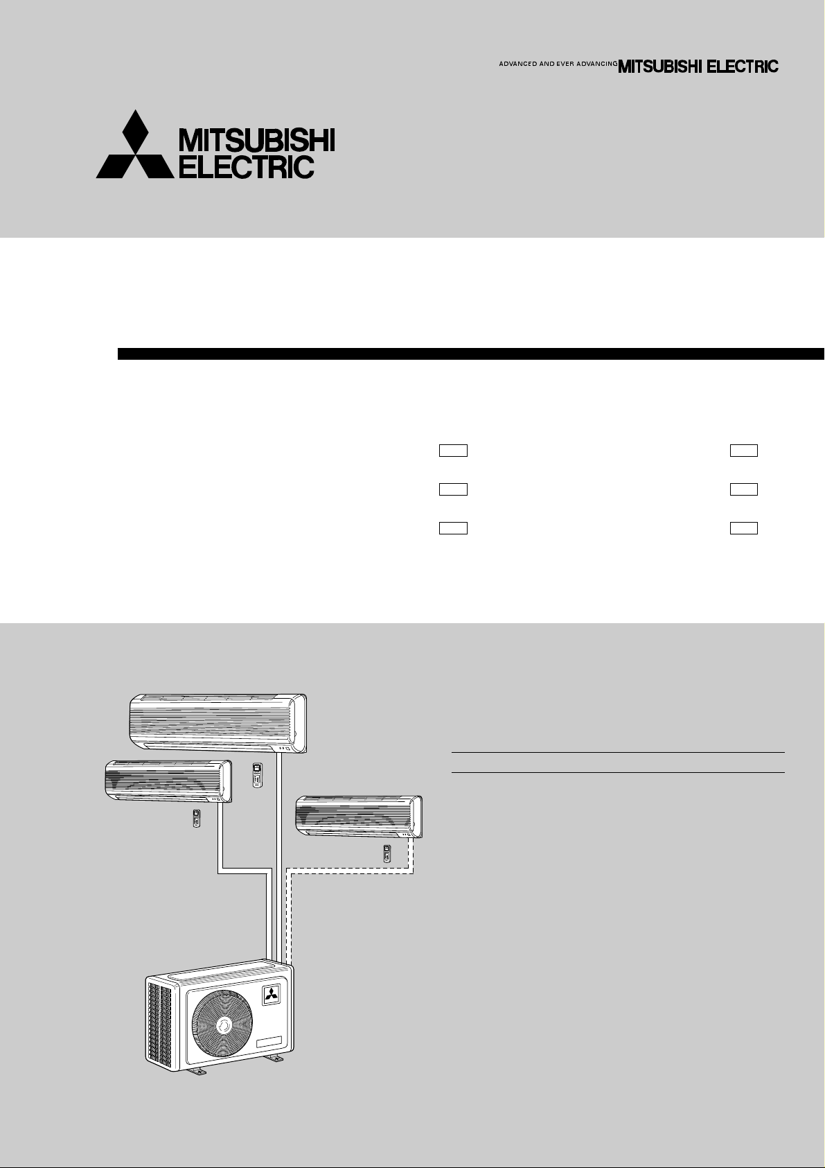
SPLIT-TYPE AIR CONDITIONERS
SERVICE MANUAL
Wireless type
Models
MSX-05NV -
(WH)●
No. OB183
SECOND EDITION
MUX-10NV -
E1E1
MSX-09NV MSX-12NV -
(WH)●
(WH)●
CONTENTS
1. TECHNICAL CHANGES ····································2
2. PART NAMES AND FUNCTIONS······················3
3. SPECIFICATION·················································6
4. OUTLINES AND DIMENSIONS·························9
5. WIRING DIAGRAM···········································11
6. REFRIGERANT SYSTEM DIAGRAM··············14
7. PERFORMANCE CURVES······························21
8. MICROPROCESSOR CONTROL ····················23
9. SERVICE FUNCTIONS ····································30
10. TROUBLESHOOTING ······································31
11. DISASSEMBLY INSTRUCTIONS·····················37
12. PARTS LIST······················································46
13. OPTIONAL PARTS ····································BACK
MUX-18NV MUX-24NV -
E1E1
E1E1
Page 2
1
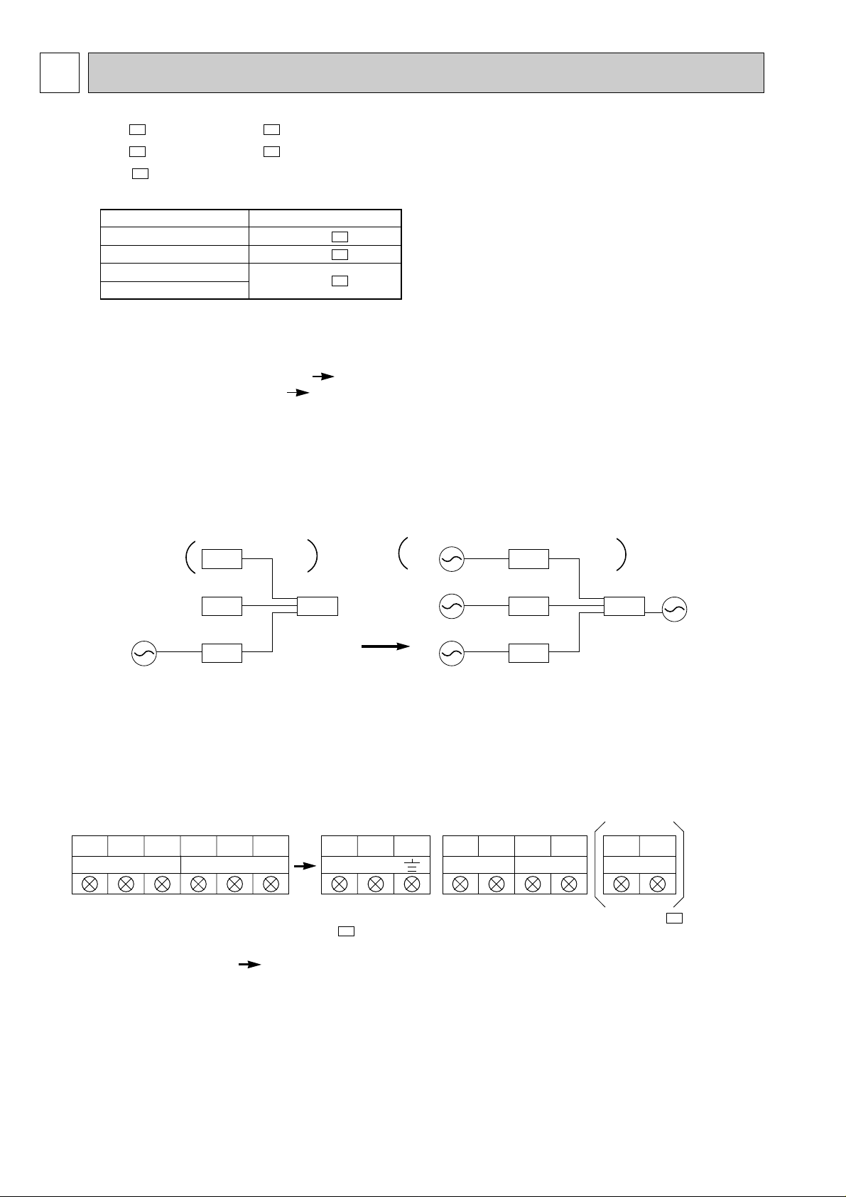
TECHNICAL CHANGES
MSX-10LV- ➔ MSX-10NVMSX-18LV- ➔ MSX-18NVMSX-24NV- New model
E1
E1E2
E1E2
Connectable unit table
INDOOR UNIT OUTDOOR UNIT
MSX-05NV x 2 MUX-10NVMSX-09NV x 2 or x 3 MUX-18NVMSX-09NV x 1 or x 2
MSX-12NV x 1 or x 2
MUX-24NV-
E1
E1
E1
It is not connected except above connection of indoor unit and outdoor unit.
1. Indoor unit model has changed.
2. Indoor fan motor has changed. (RC2V17-AA RC4V19-AA)
3. Compressor has changed. (KH-134VLC KH-134VLL)
4. Remote controller model has changed.
5. Microprocessor controller has changed.
6. The receiving system has changed.
INDOOR
220/240V
OUTDOOR INDOOR
220/240V.50Hz
220/240V
MSX-18NV
220/240V.50Hz
12VDC
12VDC
OUTDOOR
MSX-18NV
220/240V
220/240V.50Hz
50Hz
220/240V
7. Terminal block has changed.
LN2LN2 2121LN 2 1
8. Wiring diagram has changed.
9. Compressor protector has changed. (MSX-18NV- )
THERMAL SWITCH
OVERCURRENT RELAY OVERCURRENT RELAY (INNER THERMOSTAT)
E1
12VDC
220/240V
50Hz
MSX-18NV-
E1
2
Page 3
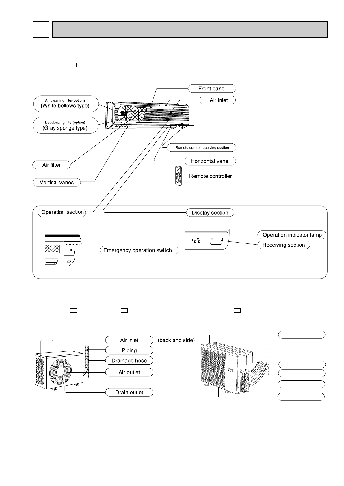
2
PART NAMES AND FUNCTIONS
INDOOR UNIT
MSX-05NV- , MSX-09NV- , MSX-12NV-
(When the front panel is open)
E1E1E1
OUTDOOR UNIT
MUX-10NV- , MUX-18NV-
E1E1
MUX-24NV-
E1
Air inlet
(back and side)
Piping
Drainage hose
Air outlet
Drain outlet
3
Page 4
.
MSX-05NVMSX-09NV-
E1
E1
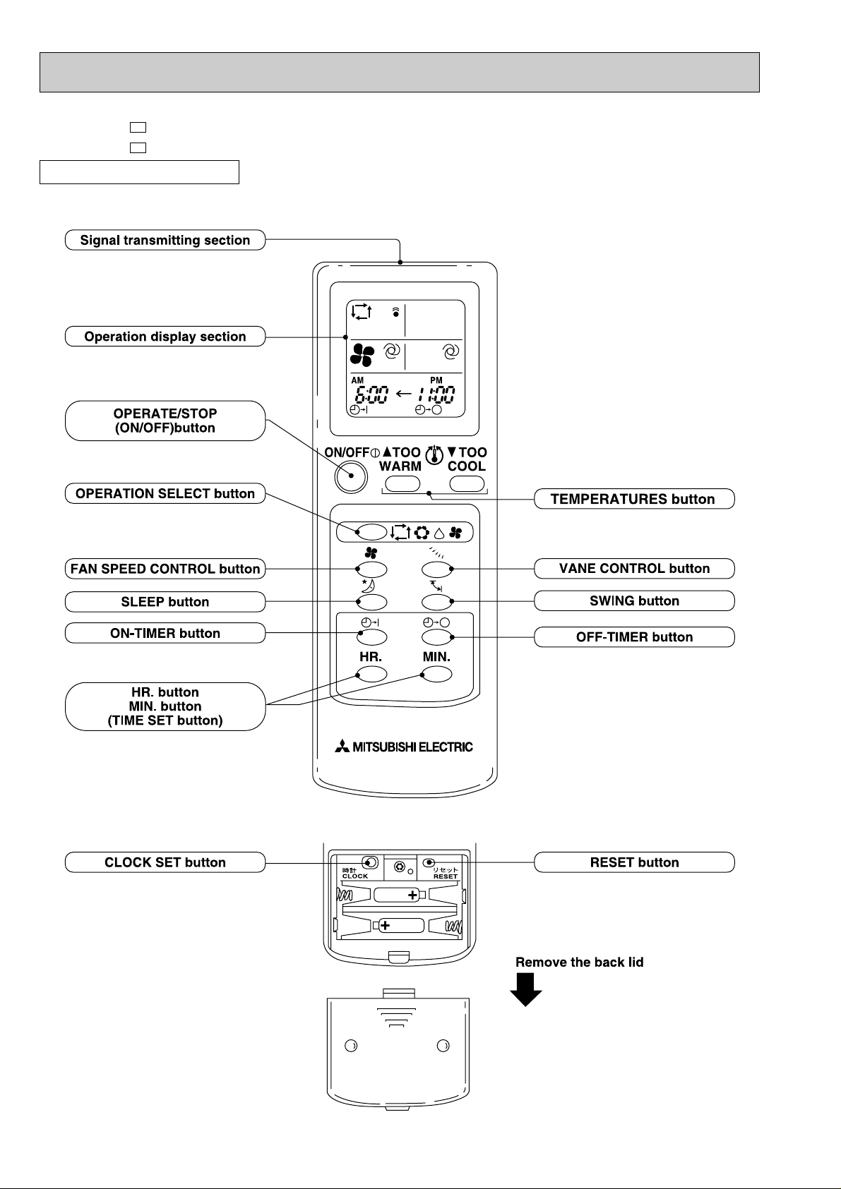
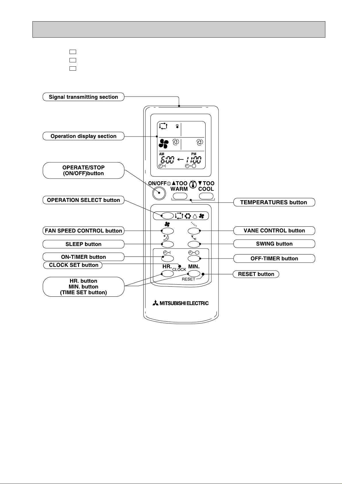
REMOTE CONTROLLER
4
Page 5
MSX-05NV- (Product number 7000501T~)
MSX-09NV- (Product number 7000701T~)
MSX-12NV-
E1
E1
E1
5
Page 6
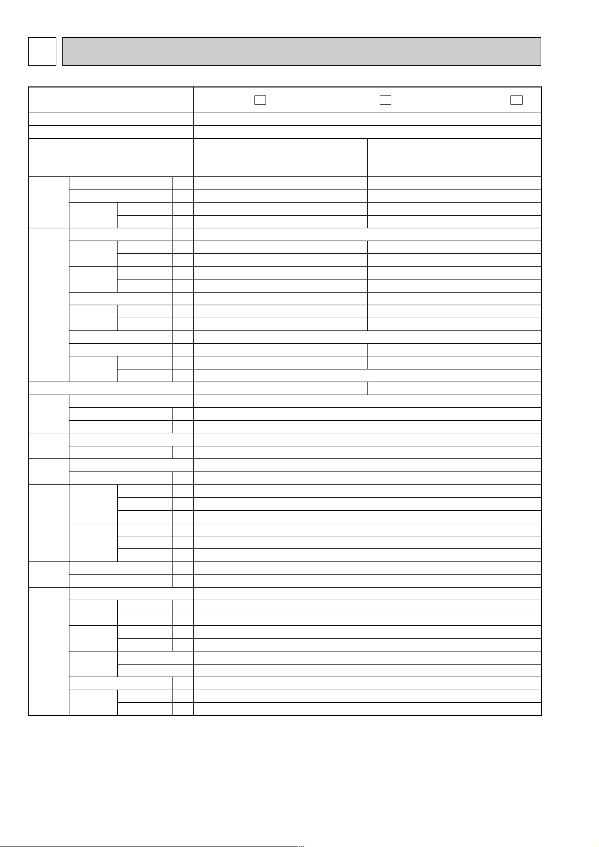
Model
Function
Power supply
Unit No.
Capacity
Dehumidification
Air flow
Power outlet
Running
current
Power input
Auxiliary heater
Power factor
Starting current
Compressor motor current
Fan motor
current
Model
Output
Winding resistance (at 20:)
Model
Winding resistance (at 20:)
Model
Winding resistance (at 20:)
Indoor unit
Outdoor unit
Indoor unit
Outdoor unit
Air direction
Sound level
(Hi)
Fan speed
(Hi)
Fan speed
regulator
Refrigerant filling capacity(R-22)
Thermistor
kW
R/h
K/h
K/h
A
A
A
W
W
A(kW)
%
%
A
A
A
A
W
"
"
"
mm
mm
mm
mm
mm
mm
kg
kg
dB
dB
rpm
rpm
kg
k"
k"
KH - 134VLL
650
C -R 4.66 C -S 8.20
RC4V 19 - A A
WHT - BLK 292 BLK - RED 324
RA6V22 - BC
WHT - BLK 325.0 BLK - RED 393.3
815
275
183
760
540
230
8
31
5
37
46 - 47
1,100
700
4
1
1.15
10
10
Capacity
Electrical
data
Coefficient of performance(C.O.P)
Compressor
Indoor
fan motor
Outdoor
fan motor
Dimensions
Weight
Special
remarks
Indoor
Outdoor
Indoor
Outdoor
Indoor
Outdoor
Indoor
Outdoor
Indoor unit
Outdoor unit
Width
Height
Depth
Width
Height
Depth
Indoor unit
Outdoor unit
Indoor unit
Outdoor unit
Indoor unit
Outdoor unit
RT11(at 25:)
RT12(at 25:)
MSX-10NV-
E1
OUTDOOR
Cooling
Single phase, 220-240V, 50Hz
MUX-10NV-
E1
INDOOR MSX-05NV-
E1
Single
A or B
2.2
0.8
492
1,560
0.17
3.33-3.43
35
705-755
–
94–86
96-92
3.05-3.15
0.17
2.97-2.78
Double
A + B
1.3x2
0.2x2
492x2
1,560
0.17x2
3.36-3.46
35x2
720-760
–
94–86
97-92
3.25-3.35
0.17x2
3.29-3.13
10
17
0.27
3
SPECIFICATION
NOTE:Test conditions
Cooling : Indoor DB27°C / WB19°C
6
Outdoor DB35°C / WB24°C
Page 7
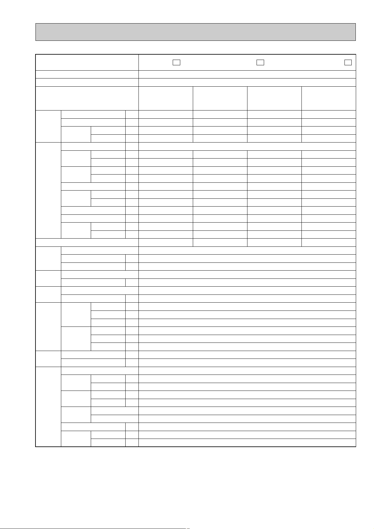
Model
Function
Power supply
Unit No.
Capacity
Dehumidification
Air flow
Power outlet
Running
current
Power input
Auxiliary heater
Power factor
Starting current
Compressor motor current
Fan motor
current
Model
Output
Winding resistance (at 20:)
Model
Winding resistance (at 20:)
Model
Winding resistance (at 20:)
Indoor unit
Outdoor unit
Indoor unit
Outdoor unit
Air direction
Sound level
(Hi)
Fan speed
(Hi)
Fan speed
regulator
Refrigerant filling capacity(R-22)
Thermistor
kW
R/h
K/h
K/h
A
A
A
W
W
A(kW)
%
%
A
A
A
A
W
"
"
"
mm
mm
mm
mm
mm
mm
kg
kg
dB
dB
rpm
rpm
kg
k"
k"
KH-134VLLx2
650x2
C-R 4.66, C-S 8.20
RC4V19-AA
WHT-BLK 292 BLK-RED 324
RA6V50-CB or RA6V50-CC
WHT-BLK117.3 BLK-YLW 65 YLW-RED 49.6
815
275
183
850
605
290
8
54
5
37
53
1,100
830-860
4
2
0.75+0.75
10
10
Capacity
Electrical
data
Coefficient of performance(C.O.P)
Compressor
Indoor
fan motor
Outdoor
fan motor
Dimensions
Weight
Special
remarks
Indoor
Outdoor
Indoor
Outdoor
Indoor
Outdoor
Indoor
Outdoor
Indoor unit
Outdoor unit
Width
Height
Depth
Width
Height
Depth
Indoor unit
Outdoor unit
Indoor unit
Outdoor unit
Indoor unit
Outdoor unit
RT11(at 25:)
RT12(at 25:)
MSX-18NV-
E1
OUTDOOR UNIT
Cooling
Single phase, 220-240V, 50Hz
MUX-18NV-
E1
INDOOR UNIT MSX-09NV-
E1
Double
A + B or A + C
2.1x2
0.8x2
492x2
1,980
0.17x2
7.06-7.16
35x2
1500-1580
–
94-86
97-92
17x2
6.67-6.77
0.17x2
0.37
2.68-2.55
Single
A or B or C
2.3
0.9
492
1,320
0.17
3.63-3.73
35
755-795
–
94-86
95-89
17
3.3-3.4
0.17
0.32
2.91-2.77
Double
B + C
1.3x2
0.2x2
492x2
1,320
0.17x2
3.66-3.76
35x2
760-810
–
94-86
94-90
17
3.32-3.42
0.17x2
0.32
3.13-2.95
Triple
A + B + C
2.1+1.3x2
0.8+0.2x2
492x3
1,980
0.17x3
7.09-7.19
35x3
1495-1585
–
94-86
96-92
17x2
6.69-6.79
0.17x3
0.37
2.94-2.78
15
NOTE:Test conditions
Cooling : Indoor DB27°C / WB19°C
Outdoor DB35°C / WB24°C
7
Page 8
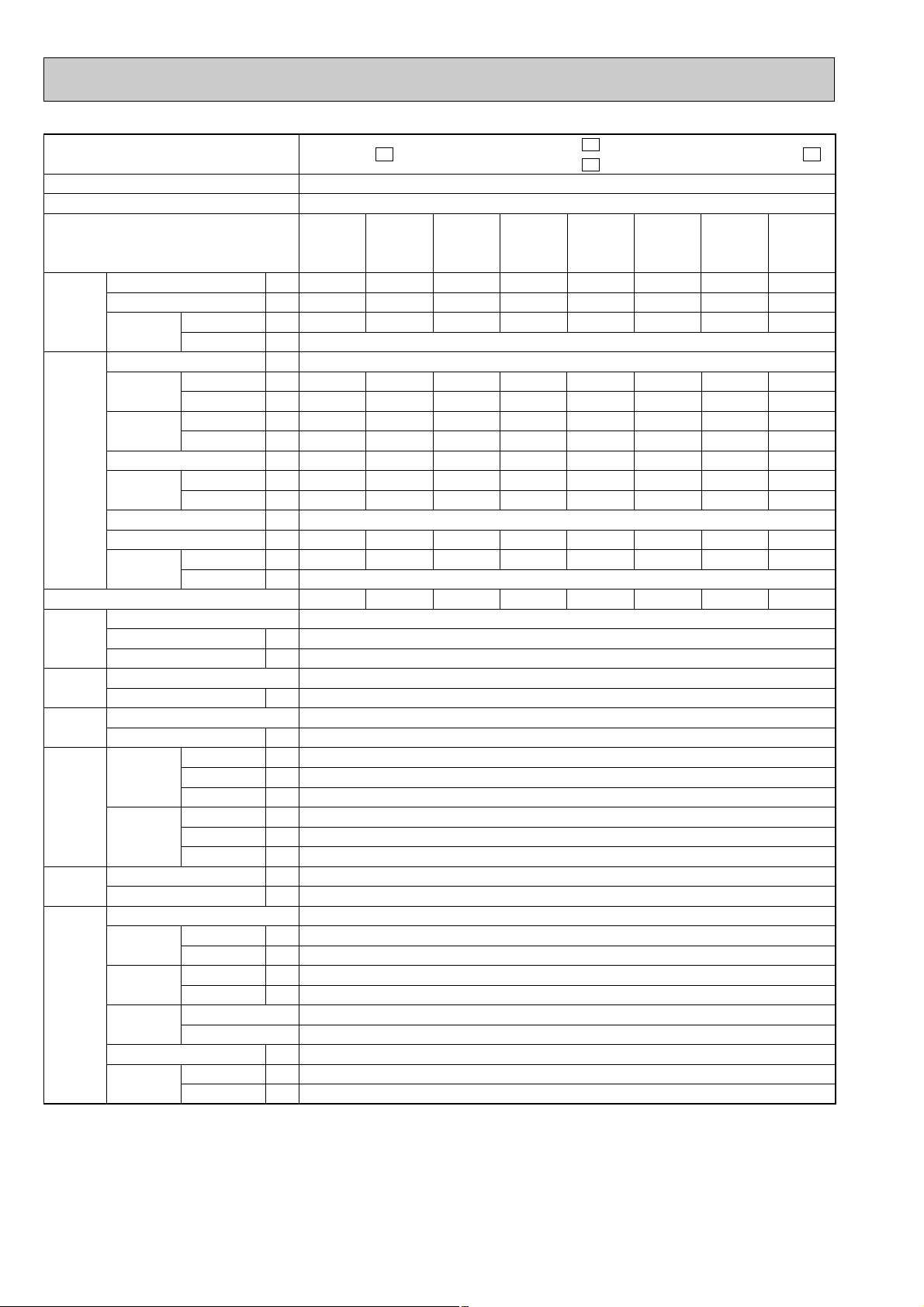
Model
Function
Power supply
Unit No.
Capacity
Capacity
Dehumidification
Air flow
Indoor
Outdoor
Power outlet
Electrical
data
Running
current
Power input
Auxiliary heater
Power factor
Indoor
Outdoor
Indoor
Outdoor
Indoor
Outdoor
Starting current
Compressor motor current
Fan motor
current
Indoor unit
Outdoor unit
Coefficient of performance(C.O.P)
Model
Compressor
Output
Winding resistance (at 20:)
Indoor
fan motor
Outdoor
fan motor
Model
Winding resistance (at 20:)
Model
Winding resistance (at 20:)
Width
Indoor unit
Dimensions
Outdoor unit
Height
Depth
Width
Height
Depth
Weight
Indoor unit
Outdoor unit
Air direction
Special
remarks
Sound level
(Hi)
Fan speed
(Hi)
Fan speed
regulator
Indoor unit
Outdoor unit
Indoor unit
Outdoor unit
Indoor unit
Outdoor unit
Refrigerant filling capacity(R-22)
Thermistor
RT11(at 25:)
RT12(at 25:)
NOTE:Test conditions
Cooling : Indoor DB27°C / WB19°C
Outdoor DB35°C / WB24°C
MSX-24NV- E1INDOOR UNIT OUTDOOR UNIT
MSX-09NVMSX-12NV-
E1
E1
Cooling
Single phase, 220-240V, 50Hz
Double
A+C or A+D
B+C or B+D
3.1+2.3
1.4+0.8
558+492
2400-2640
25
0.17x2
10.8-10.4
35x2
2.33-2.40
–
94–86
97-96
48
10.6-10.2
0.17x2
0.28-0.31
2.25-2.19
A+B+C or
1.95x2+2.2
0.5x2+0.8
558x2+492
kW
R/h
K/h
K/h
A
A
A
W
kW
A(kW)
%
%
A
A
A
A
Single
A or B
3.4
1.6
558
0.17
6.2-6.0
35
1.32-1.38
–
94–86
97-96
6.2-6.0
0.17
2.51-2.40
Single
C or D
2.6
1.2
492
0.17
4.4-4.3
35
0.94-0.98
–
94–86
97-96
4.4-4.2
0.17
2.67-2.56
Double
A+B
2.0x2
0.5x2
558x2
0.17x2
6.5-6.5
35x2
1.39-1.49
–
94–86
97-96
6.2-6.0
0.17x2
2.74-2.56
Double
C+D
1.7x2
0.3x2
492x2
0.17x2
4.6-4.4
35x2
0.98-1.02
–
94–86
97-96
4.4-4.2
0.17x2
3.24-3.12
RH-174VGH+RH-231VHA
W
"
RH-174VGH C-R3.30 C-S5.80 RH-231VHA C-R2.13 C-S3.91
RH-174VGH 800 RH-231VHA 1100
RC4V19-AA
"
WHT-BLK 292 BLK-RED 324
RA6V25-AA
"
mm
mm
mm
mm
mm
mm
kg
kg
WHT-BLK142 BLK-RED135
815
275
183
750
900
330
8
72
5
dB
dB
rpm
rpm
MSX-09NV 37 MSX-12NV 42
49
MSX-09NV 1100 MSX-12NV 1230
530-570
4
1
kg
k"
k"
1.15+1.15
10
10
Triple
A+B+D
0.17x3
11.1-10.6
35x3
2.37-2.45
–
94–86
97-96
10.6-10.2
0.17x3
2.46-2.39
MUX-24NV-
Triple
A+C+D or
B+C+D
2.9+1.55x2
1.3+0.3x2
558+492x2
0.17x3
11.1-10.6
35x3
2.37-2.45
–
94–86
97-96
10.6-10.2
0.17x3
2.42-2.35
E1
Four
A+B+C+D
1.95x2+1.55x2
0.5x2+0.3x2
558x2+492x2
0.17x4
11.5-10.9
35x4
2.45-2.50
–
94–86
97-96
10.6-10.2
0.17x4
2.70-2.65
8
Page 9
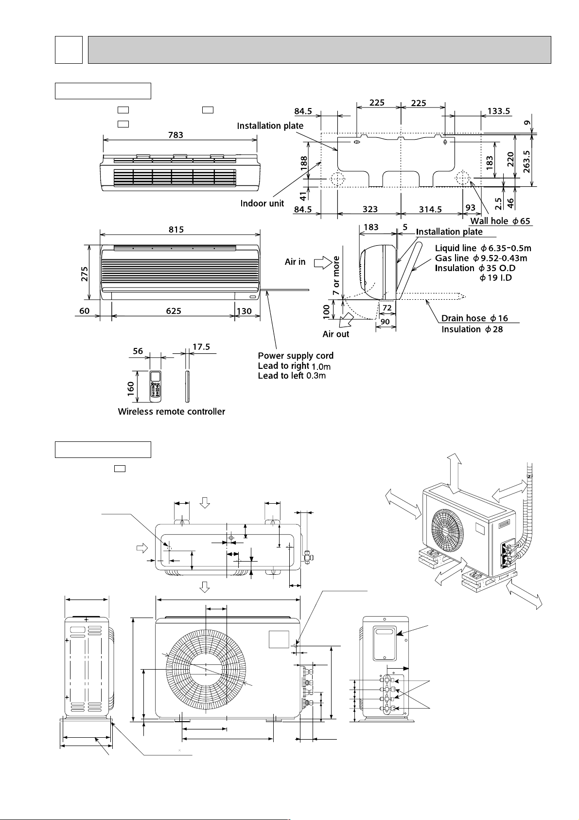
230
260
295
Bolt pitch
4 holes 10 21
Bolt pitch for installation
500
250
10
262.5
540
760
112
Wiring hole
Rear side
20
63
384.5
67 57
57
57
57
68
68
Stop valve 1/4F
Stop valve 3/8F
151
Service panel
58
60
21
35
50
70
50
50
56
105
Air in
Air in
Air out
Drainage
4 hole
[16.2
108
ø415
35cm or more
50cm or more
10cm or more
10cm or more
Unless any obstacle
exists in front ,right
Unless any obstacle
exists in front
and left sides.
10cm or more
Unless any obstacle
exists in right , left and
rear sides.
REQUIRED SPACE
Unit A
4
OUTLINES AND DIMENSIONS
INDOOR UNIT
MSX-05NV- , MSX-09NVMSX-12NV-
E1
Unit : mm
E1E1
OUTDOOR UNIT
MUX10NV-
E1
9
Page 10
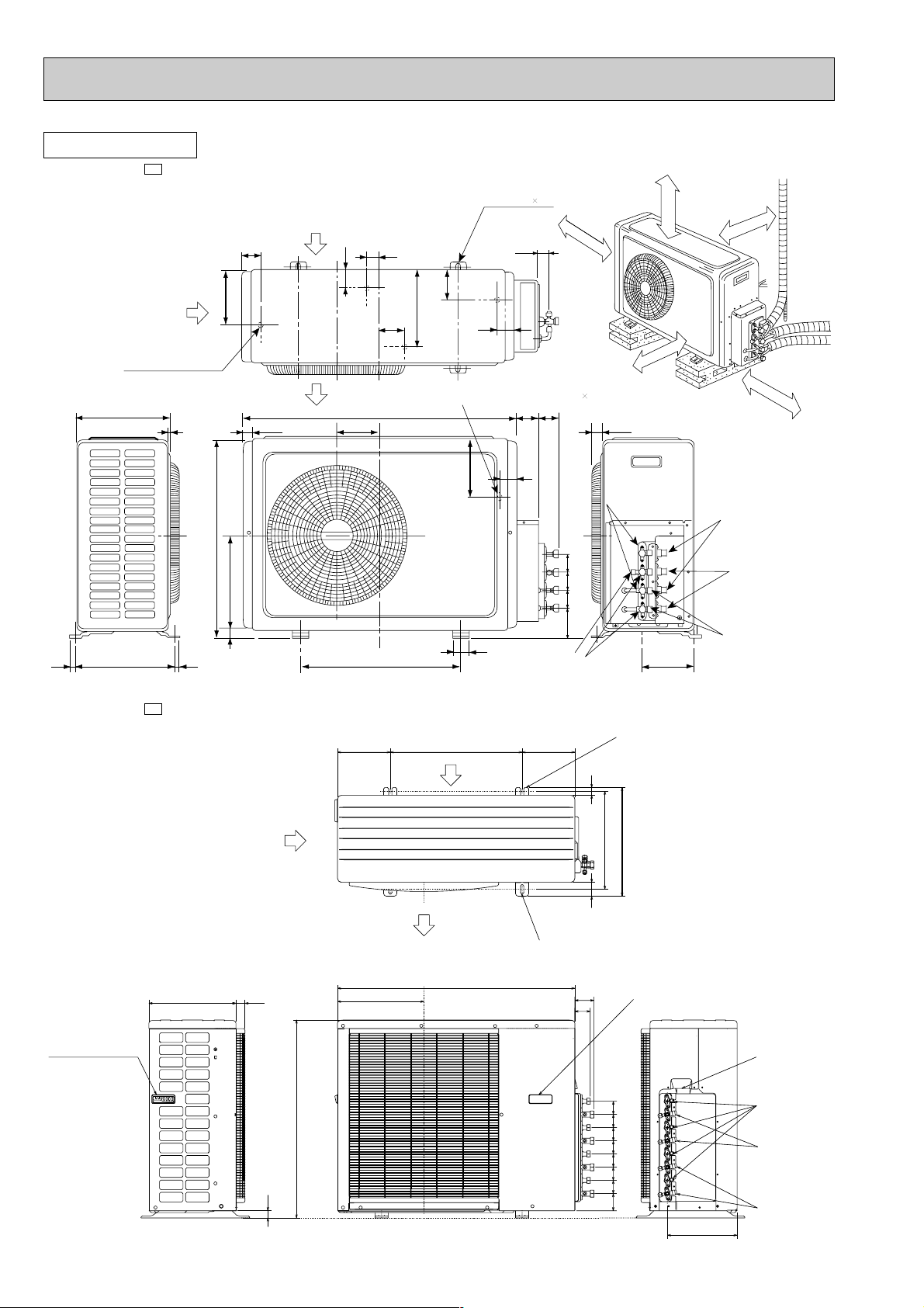
16 310 16
290
530
605
292
20
500
Bolt pitch for installation
50
90 57 57 57
Service port
Stop valve
3/8F
A
154.6
Service portBC
Gas side
union
3/8F
Liquid side
union
1/4F
Stop valve 1/4F
30
52
186
70 66
Electrical wiring entrance (Rear) 15 25
Unless any
obstacle exists
in right ,left ,
and rear sides.
C
B
Unless any
obstacle exists
in front, right
and left sides.
REQUIRED SPACE
4 holes-10 21
34
35
5480
236
91
51
168
57
850
133
Air out
Air in
4 Drain holes [
16.2
Air in
10cm or more
50cm or more
35cm or more
10cm or more
10cm or more
A
OUTDOOR UNIT
MUX-18NV-
E1
MUX-24NV-
Handle for moving
10
E1
Air in
34330
750
27
200 200500
Air in
Air out
900
328
2-Oval hols(12Å~36)
(Base bolt M10)
2-U-Shape noched hols
(Base bolt M10)
29
412
372
53
Handle for moving
72.2
58.2
5050505050
50
50
64.8
264.2
Wiring hole
Liquid pipe
(flared ɔ6.35)
Gus pipe
(flared ɔ12.7)
Gus pipe
(flared ɔ9.52)
Page 11
WHT
WHT
BRN
F13
F12
CIRCUIT BREAKER
WHT
1
TB2
2
TB2
TB3
1
BLU
BLU
BLK
RED
C2
221
1
43
X1
4X23
BLU
BLU
BLU
BLU
RED
YLW
RED
YLW
BLU
BRN
BLU
BLU
BLU
BRN
WHT
BRN
WHT WHTBRN
NO COM
52C1
NO
52C2
COM
3
1
RED
BLU
RED
BLK
21R2
21R1
21R
52C1
TB
52C2
MF
WHT
2
WHT
1
51C
R
S
MC
C
X2
N
L
POWER SUPPLY
220-240V
50Hz
GRN/YLW
BLK
12VDC
12VDC
WHT
ORN
GRY
TO INDOOR
UNIT No.A
CONNECTING
X1
1
2
1
2
TO INDOOR
UNIT No.B
CONNECTING
2
TB3
C1
CIRCUIT BREAKER
POWER
SUPPLY
CORD
50Hz
F12
12VDC
12VDC
TO OUTDOOR
UNIT
CONNECTING
TB
2
1
1
1
2
L
N
2
CN202
1
BLU
BLU
BLU
BLK
WHT
BRN
BRN
BLU
BLU
GRN/YLW
GRN/YLW
220-240V
~/N
GUARD
PLATE
TRANS
HIC1
MV
POWER MONITOR,
RECEIVER
P.C.BOARD
REMOTE
CONTROLLER
F11
NR11
ELECTRONIC CONTROL P.C BOARD
1
122
CN
TAB12
5
LD101
151
CN
CN201
MF
RT11
RT12
SR11
C11
5
4
3
2
6
1
3
2
1
3
CN211
111
CN
CN
112
121
CN
RED
WHT
BRN
YLW
GRY
BLK
5
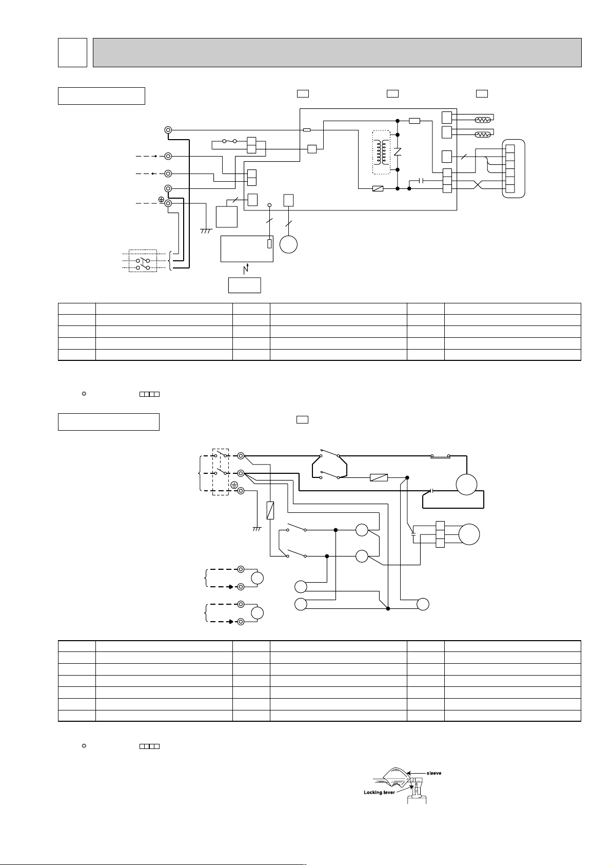
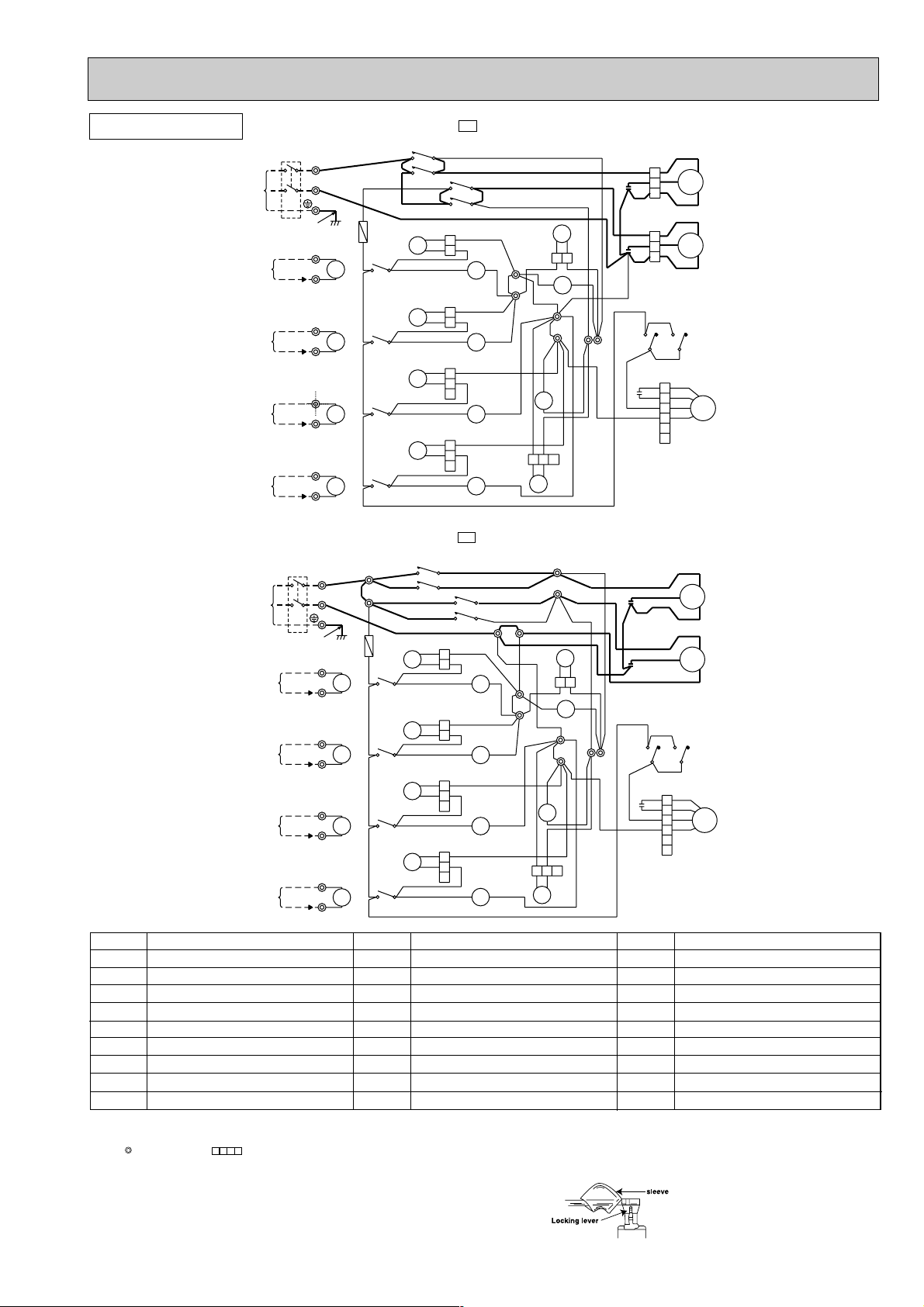
WIRING DIAGRAM
INDOOR UNIT
MODELS MSX-05NV- , MSX-09NV- , MSX-12NV-
❈
❈
SYMBOL
C11
F11
MF
MV
NAME
INDOOR FAN CAPACITOR
FUSE(3.15A)
FAN MOTOR
VANE MOTOR
SYMBOL
NR11
RT11
RT12
SR11
NAME
VARISTOR
ROOM TEMPERATURE THERMISTOR
INDOOR COIL TEMPERATURE THERMISTOR
SOLID STATE RELAY
NOTE:1. About the outdoor side electric wiring refer to the outdoor electric wiring diagram for servicing.
2. Use copper conductors only.(For field wiring)
3. Symbols below indicate.
: Terminal block, : Connector
SYMBOL
HIC1
TB
F12
E1E1E1
NAME
DC/DC CONVERTER
TERMINAL BLOCK
FUSE (93;)
OUTDOOR UNIT
MODEL MUX-10NV-
E1
❈
❈
❈
❈
❈
❈
❈
❈
❈
❈
❈
❈
SYMBOL
TB,TB2,TB3
TERMINAL BLOCK
RELAY(A)
X1
RELAY(B)
X2
21R
21R1
21R2
BYPASS VALVE SOLENOID COIL
SOLENOID COIL(A)
SOLENOID COIL(B)
.
NAME
SYMBOL
C1
COMPRESSOR CAPACITOR
C2
OUTDOOR FAN CAPACITOR
F12
F13
MC
MF
NOTE:1. Use copper conductors only.(For field wiring)
FUSE(2A)
FUSE(2A)
COMPRESSOR(B,C)
FAN MOTOR
2. Symbols below indicate.
: Terminal block, : Connector
3. ❈ on the wiring diagram shows the terminals with a lock mechanism, so it cannot be removed when you pull the lead wire Be sure to pull the wire by pushing
the locking lever (projected part) of the terminal with a finger
NAME
SYMBOL
NAME
OVER CURRENT RELAY(INNER THERMOSTAT)
51C1
52C1
COMPRESSOR CONTACTOR(A)
52C2
COMPRESSOR CONTACTOR(B)
① Slide the sleeve.
➁ Pull the wire while pushing the locking
lever.
11
Page 12
TO INDOOR
UNIT No.A
CONNECTING
TO INDOOR
UNIT No.B
CONNECTING
TO INDOOR
UNIT No.C
CONNECTING
POWER SUPPLY
220-240V
50Hz
BRN
WHT
F14
BLU
GRY
F13
CIRCUIT BREAKER
YLW
RED
BRN
BLU
BLU
BLU
WHT
F12
BLU
BLU
BLU
GRY
1
TB3
TB2
1
43
43
12VDC
12VDC
12VDC
BLU
BLU
BLU
YLW
GRN/YLW
BLK
WHT
ORN
RED
YLW
51C2
BRN
YLW
BRN
BLU
WHT
WHT
WHT
RED
REDBLU
WHT
BRN
2
TB2
X2
X1
1
2
1
2
C2
C1
R
C
C
S
MC2
BLK
52CA
BLU
52C2
21R2
RED 2
X2
X1
COMNO
52CA
3
X12
5
1
MC1
51C1
1
1
52C1
X11
X11
21R
X11
X12
21R1
X12
C3
TB
52C1
52C2
1
2
L
N
4
78
4
6
2
6
2
2
87
3
1
5
3
2
4
43
BRN
BLU
BRN
BRN
WHT
GRY
WHT
BLU
BLU
R
MF
BLK
ORN
WHT
YLW
RED
BLK
5
4
2
3
1
RED
YLW
BLK
WHT
ORN
RED
GRY
S
1
1
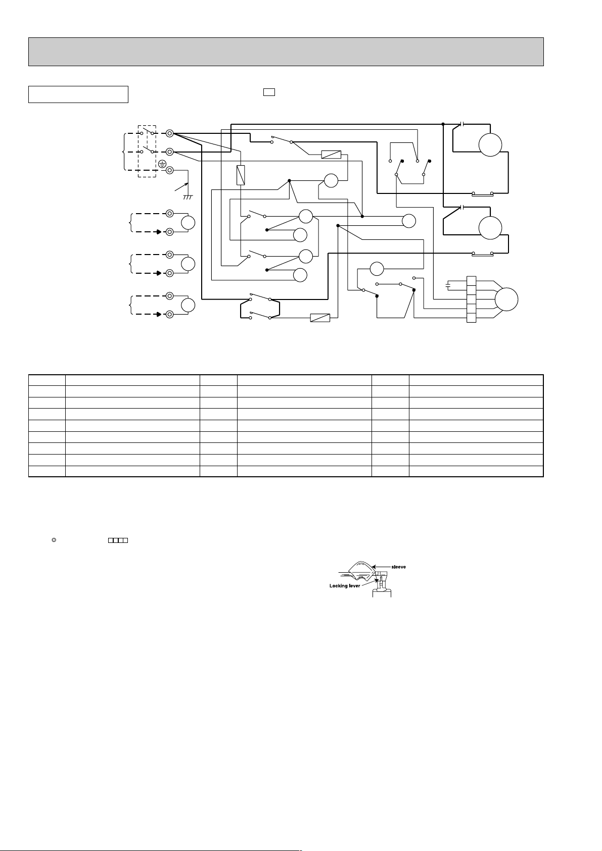
OUTDOOR UNIT
MODEL MUX-18NV-
❈
E1
SYMBOL
C1
C2
C3
MC1
MC2
MF
F12
F13
❈
❈
❈
❈
❈
❈
❈
NAME
COMPRESSOR CAPACITOR(A)
COMPRESSOR CAPACITOR(B,C)
OUTDOOR FAN CAPACITOR
COMPRESSOR(A)
COMPRESSOR(B,C)
FAN MOTOR(INNER THERMOSTAT)
FUSE(2A)
FUSE(2A)
❈1
❈2
❈1
❈2
❈1
❈2
SYMBOL
TB
X11
X12
21R
21R1
21R2
F14
TB2,TB3
❈
❈
❈
❈
❈
❈
NAME
TERMINAL BLOCK
FAN MOTOR RELAY(A)
FAN MOTOR RELAY(B,C)
SOLENOID COIL
SOLENOID COIL(B)
SOLENOID COIL(C)
FUSE(2A)
TERMINAL BLOCK
SYMBOL
51C1
51C2
52CA
52C1
52C2
X1
X2
NAME
OVER CURRENT RELAY(A)INNER THERMOSTAT
OVER CURRENT RELAY(B,C)INNER THERMOSTAT
COMPRESSOR CONTACTOR(A)
COMPRESSOR CONTACTOR(B)
COMPRESSOR CONTACTOR(C)
RELAY(B)
RELAY(C)
NOTE:1. Use copper conductors only.(For field wiring)
2. Symbols below indicate.
: Terminal block, : Connector
3. ❈ on the wiring diagram shows the terminals with a lock mechanism, so it cannot be removed when you pull the lead wire Be sure to pull the wire by
.
① Slide the sleeve.
➁ Pull the wire while pushing the locking
lever.
pushing the locking lever (projected part) of the terminal with a finger
12
Page 13
OUTDOOR UNIT
POWER SUPPLY
~/N
220-240V
50Hz
CIRCUIT
BREAKER
TO INDOOR
UNIT No.A
CONNECTING
TO INDOOR
UNIT No.B
CONNECTING
TO INDOOR
UNIT No.C
CONNECTING
TO INDOOR
UNIT No.D
CONNECTING
MODEL MUX-24NV-
4
❈
❈
❈
❈
BRN
BLU
BLU
BLU
BLU
4
BRN
BLU
21R1
21R2
21R3
21R4
52C1
52C2
BLU
BLU
BLU
BLU
BLU
BLU
BLU
BLU
3
3
BRN
ORN
ORN
ORN
ORN
4
TB
L
N
GRN/YLW
2
TB1
1
12VDC
2
TB2
1
12VDC
2
TB3
1
12VDC
2
TB4
1
12VDC
YLW
❈
❈
YLW
ORN
❈
❈
ORN
WHT
❈
❈
WHT
GRY
❈
❈
GRY
X1
X2
X3
X4
❈2
❈2
❈2
❈1
❈2
BRN
❈
❈1
❈1
❈1
❈
F
BRN
❈
BRN
BRN
BRN
BRN
❈
❈
❈
BRN
X1
4
X2
4
X3
4
X4
4
3
3
3
3
E1
5
GRY
ORN
WHT
YLW
1
RED
2
3
1
RED
2
3
BRN
1
WHT
1
2
3
4
5
6
C
WHT
MC1
S
R
BLK
C
WHT
MC2
S
R
BLK
1
❈
3
X11
5
❈
RED
ORN
WHT
MF
BLK
WHT
WHT
3
52C4
WHT
2
BLU
BLU
2
2
2
BLU
BLU
TB6
BLU
BLU
2
1
WHT
BLU
BLU
BLU
BLU
❈
7
X12
BLU
21RB
7
2
BLU
321
BLU
21RA
21
X11
TB5
BLU
8
BLU
BLU
BLU
ORN
8
WHT
52C3
3
4
BLU
1
2
52C1
1
BLU
1
2
52C2
1
BLU
1
2
3
52C3
1
BLU
1
2
3
52C4
1
TB7
BLU
12
WHT
RED
C1
BLK
BLU
WHT
RED
C2
❈
BLK
3
X12
C11
SYMBOL
C1
C2
C11
MC1
MC2
MF
F
21RA
21RB
MODEL MUX-24NV-
TB
L
POWER SUPPLY
~/N
220-240V
50Hz
CIRCUIT
BREAKER
TO INDOOR
UNIT No.A
CONNECTING
TO INDOOR
UNIT No.B
CONNECTING
TO INDOOR
UNIT No.C
CONNECTING
TO INDOOR
UNIT No.D
CONNECTING
NAME
COMPRESSOR CAPACITOR(A,B)
COMPRESSOR CAPACITOR(C,D)
FAN MOTOR CAPACITOR
COMPRESSOR(A,B)
COMPRESSOR(C,D)
FAN MOTOR(INNER THERMOSTAT)
FUSE(3.15A)
SOLENOID COIL
SOLENOID COIL
N
GRN/YLW
2
TB1
1
12VDC
2
TB2
1
12VDC
2
TB3
1
12VDC
GRY
2
TB4
1
12VDC
YLW
❈
❈
YLW
ORN
❈
❈
ORN
WHT
❈
❈
WHT
❈
❈
GRY
BRN
❈2
X1
❈1
❈2
X2
❈1
❈2
X3
❈1
❈2
X4
❈1
BRN
2
BRN
TB10
BRN
BRN
1
BRN
❈
F
❈
X1
❈
BRN
4
3
BRN
X2
❈
4
3
BRN
X3
❈
4
3
BRN
X4
❈
4
3
BRN
SYMBOL
TB
X11
X12
21R1
21R2
21R3
21R4
TB1~TB10
E1
4
3
52C1
4
52C2
BRN
BLU
BLU
21R1
BLU
BLU
❈
BLU
21R2
BLU
BLU
❈
BLU
21R3
BLU
BLU
❈
BLU
21R4
BLU
BLU ORN
❈
WHT
3
WHT
4
3
52C4
4
3
52C3
BLU
1
2
ORN
52C1
1
2
BLU
1
2
ORN
52C2
2
1
BLU
1
2
3
ORN
52C3
1
BLU
1
2
3
52C4
1
TERMINAL BLOCK
FAN MOTOR RELAY(A,B)
FAN MOTOR RELAY(B,C)
SOLENOID COIL(A)
SOLENOID COIL(B)
SOLENOID COIL(C)
SOLENOID COIL(D)
TERMINAL BLOCK
(Product number 700501~)
1
WHT
TB9
2
WHT
BLU
BLU
BLU
BLU
BLU
7
X12
BLU
21RB
21RA
21
X11
7
TB5
BLU
BLU
8
BLU
321
BLU
WHT
BLU
BLU
ORN
8
❈
2
2
1
1
TB7
WHT
BLU
BLU
2
BLU
2
NAME
BLU
TB8
BLU
BLU
WHT
BLU
TB6
BLU
12
2
1
WHT
RED
C1
BLK
BLU
WHT
RED
C2
BLK
3
X12
5
GRY
C11
ORN
WHT
YLW
SYMBOL
52C1
52C2
52C3
52C4
X1
X2
X3
X4
C
MC1
S
R
C
MC2
S
R
BRN
❈
3
1
1
X11
WHT
5
❈
RED
1
ORN
2
WHT
MF
3
BLK
4
5
6
COMPRESSOR RELAY(A)
COMPRESSOR RELAY(B)
COMPRESSOR RELAY(C)
COMPRESSOR RELAY(D)
RELAY(A)
RELAY(B)
RELAY(C)
RELAY(D)
NAME
NOTE:1. Use copper conductors only.(For field wiring)
2. Symbols below indicate.
: Terminal block, : Connector
3. ❈ on the wiring diagram shows the terminals with a lock mechanism, so it cannot be removed when you pull the lead wire Be sure to pull the wire by
pushing the locking lever (projected part) of the terminal with a finger
.
① Slide the sleeve.
➁ Pull the wire while pushing the locking
lever.
13
Page 14
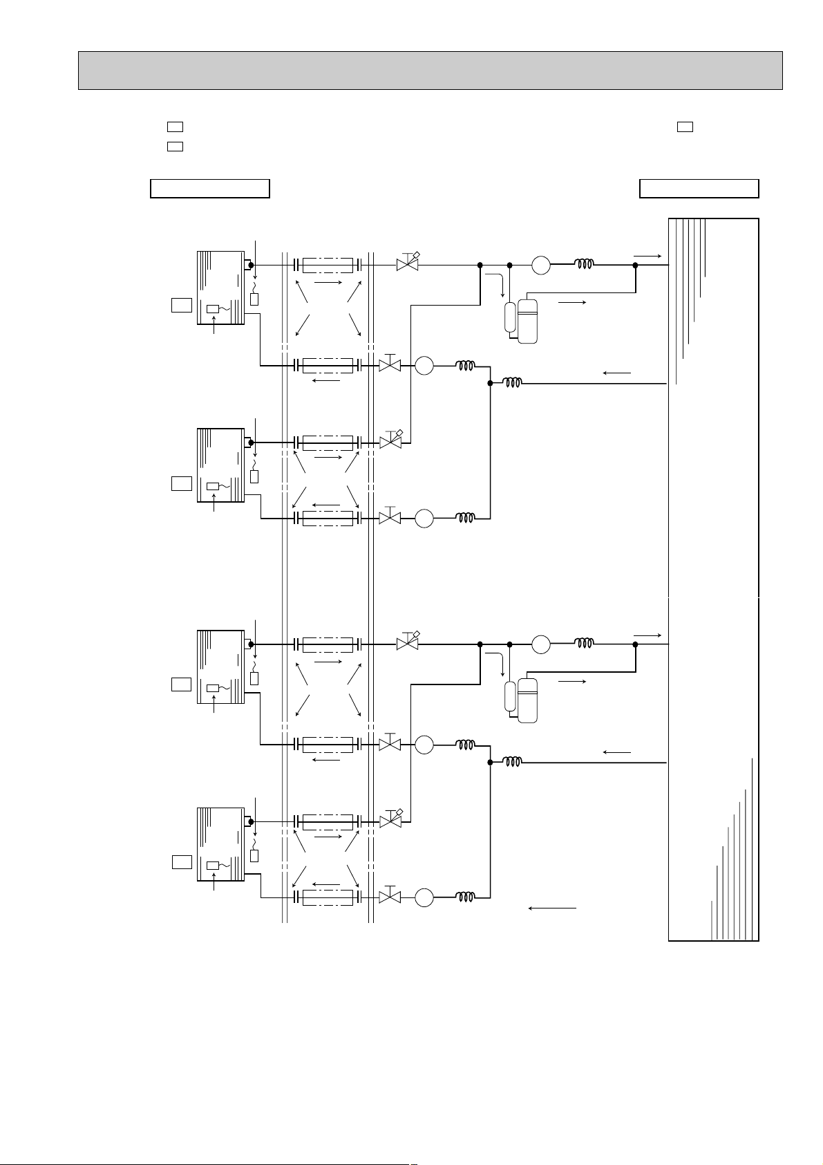
OUTDOOR UNITINDOOR UNIT
UNIT A
Indoor
heat
exchanger
Indoor coil
thermistor
RT12
Room
temperature
thermistor
RT11
UNIT B
Indoor
heat
exchanger
Outdoor
heat
exchanger
Indoor coil
thermistor
RT12
Room
temperature
thermistor
RT11
(option)
(With insulation)
Refrigerant pipe
9.52 (3/8)
(option)
(With insulation)
Refrigerant pipe
9.52 (3/8)
Flared connection
(option)
(With insulation)
Refrigerant pipe
6.35 (1/4)
(option)
(With insulation)
Refrigerant pipe
6.35 (1/4)
Flared connection
Stop valve
with service port
Solenoid valve
21R1
Solenoid valve
21R
Solenoid valve
21R2
Capillary tube
1.4 x 400
Capillary tube
1.4 x 400
Capillary tube
Capillary tube
1.4 x 200
1.6 x 1,000
Compressor
Refrigerant flow
Stop valve
with service port
Stop
valve
Stop
valve
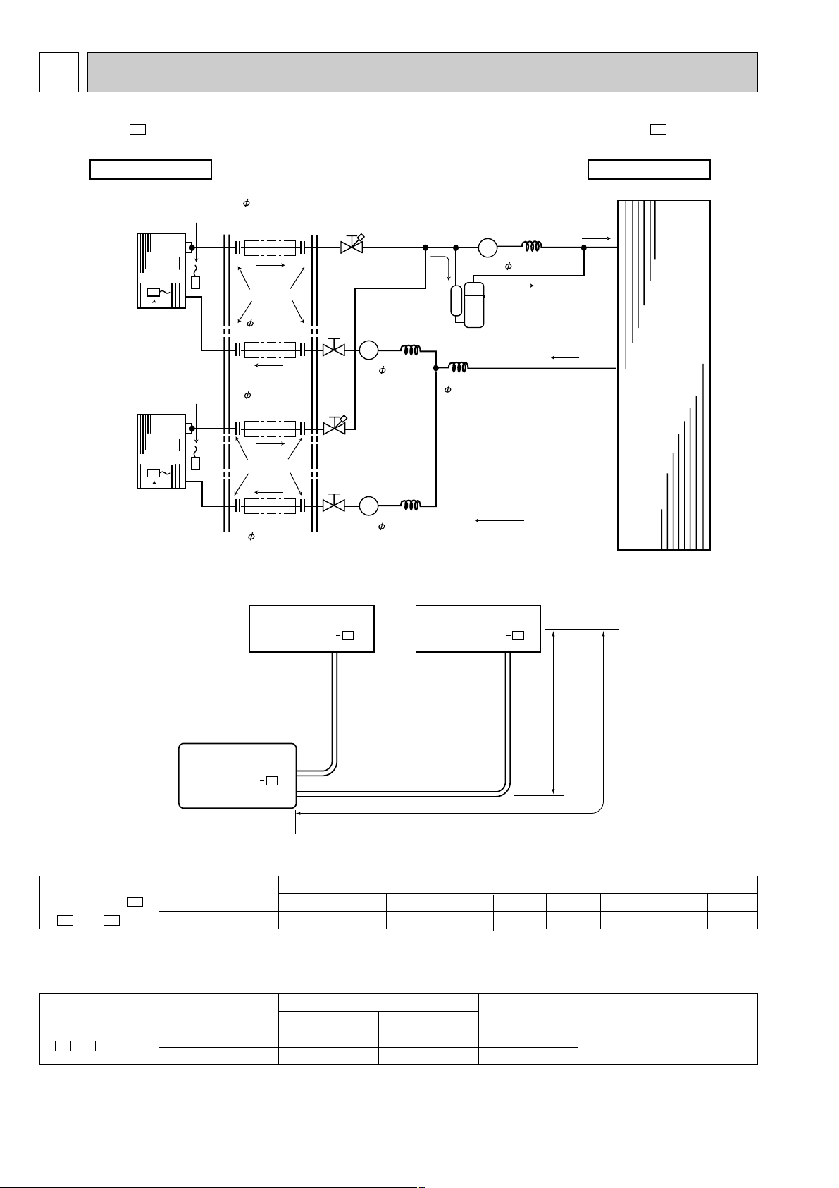
6
REFRIGERANT SYSTEM DIAGRAM
MSX-05NV-
E1
MUX-10NV-
E1
Unit : mm
MAX. REFRIGERANT PIPING LENGTH & MAX. HEIGHT DIFFERENCE
Indoor unit A
MSX-05NV
Outdoor unit
MUX-10NV
ADDITIONAL REFRIGERANT CHARGE (R-22:g)
MSX-10NV
A
E1
- precharged 7m 8m 9m 10m 11m 12m 13m 14m 15m
B
unit+ unit 1150g 0 10 20 30 40 50 60 70 80
Outdoor unit refrigerant piping length (one way,2unit total)
PIPING PREPARATION
1 Table below shows the specifications of pipes commercially available.
UNIT No. Pipe
and
BA
UNIT
For liquid 6.35 1/4 6 mm Heat resisting foam plastic
For gas 9.52 3/8 6 mm 0.045 specific gravity
E1
2 Ensure that the 2 refrigerant pipes are well insulated to prevent condensation.
3 Refrigerant bending radius must be 10cm or more.
14
E1
Additional piping max. length 10m
Outside diameter Insulation
mm inch thickness
Indoor unit B
MSX-05NV
E1
Max. length
difference
5m
Insulation material
Page 15
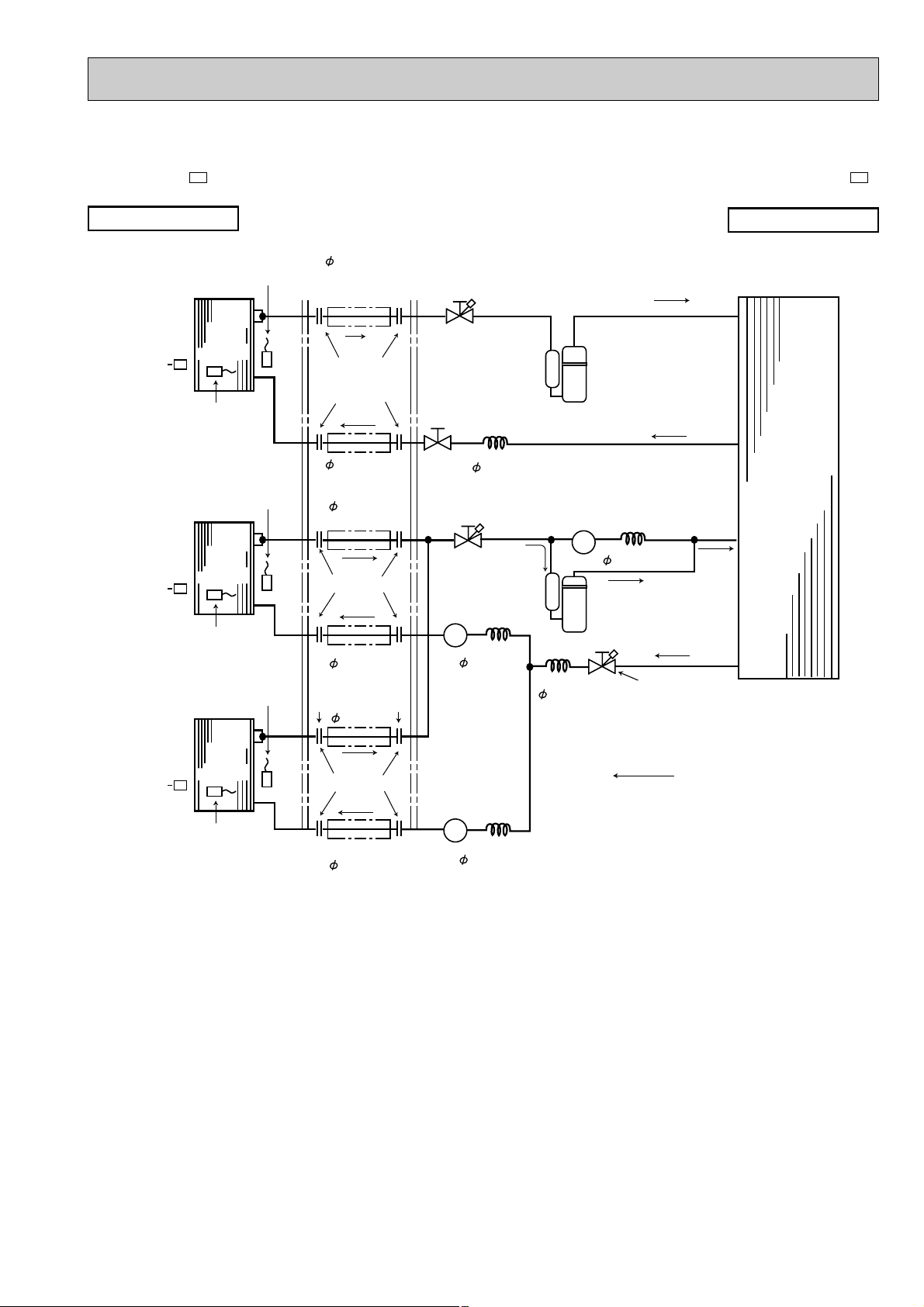
Unit : mm
MSX-09NV-
INDOOR UNIT
UNIT A
MSX-09NV
MSX-09NV
E1
UNIT B
E1
E1
Indoor
heat
exchanger
Indoor coil
thermistor
RT12
Indoor
heat
exchanger
Indoor coil
thermistor
RT12
Room
temperature
thermistor
RT11
Room
temperature
thermistor
RT11
Room
temperature
thermistor
RT11
Refrigerant pipe
9.52<3/8>
(option)
(With insulation)
Flared connection
Refrigerant pipe
6.35<1/4>
(option)
(With insulation)
Refrigerant pipe
9.52<3/8>
(option)
(With insulation)
Flared connection
Refrigerant pipe
6.35<1/4>
(option)
(With insulation)
Refrigerant pipe
9.52<3/8>
Stop valve
with service port
Stop valve
Capillary tube
Stop valve
with
service port
Solenoid valve
21R1
Capillary tube
1.4 ✕ 600
1.4 ✕ 1000
Compressor(A)
Solenoid valve
21R
Capillary tube
1.4 ✕ 150
Capillary tube
1.6 ✕ 1,000
Compressor(B,C)
Stop valve
with
service port
MUX-18NV-
OUTDOOR UNIT
Outdoor
heat
exchanger
E1
UNIT C
MSX-09NV
E1
Indoor
heat
exchanger
Indoor coil
thermistor
RT12
Flared connection
Refrigerant pipe
6.35<1/4>
(option)
(With insulation)
Refrigerant flow
Solenoid valve
21R1
Capillary tube
1.4 ✕ 600
15
Page 16
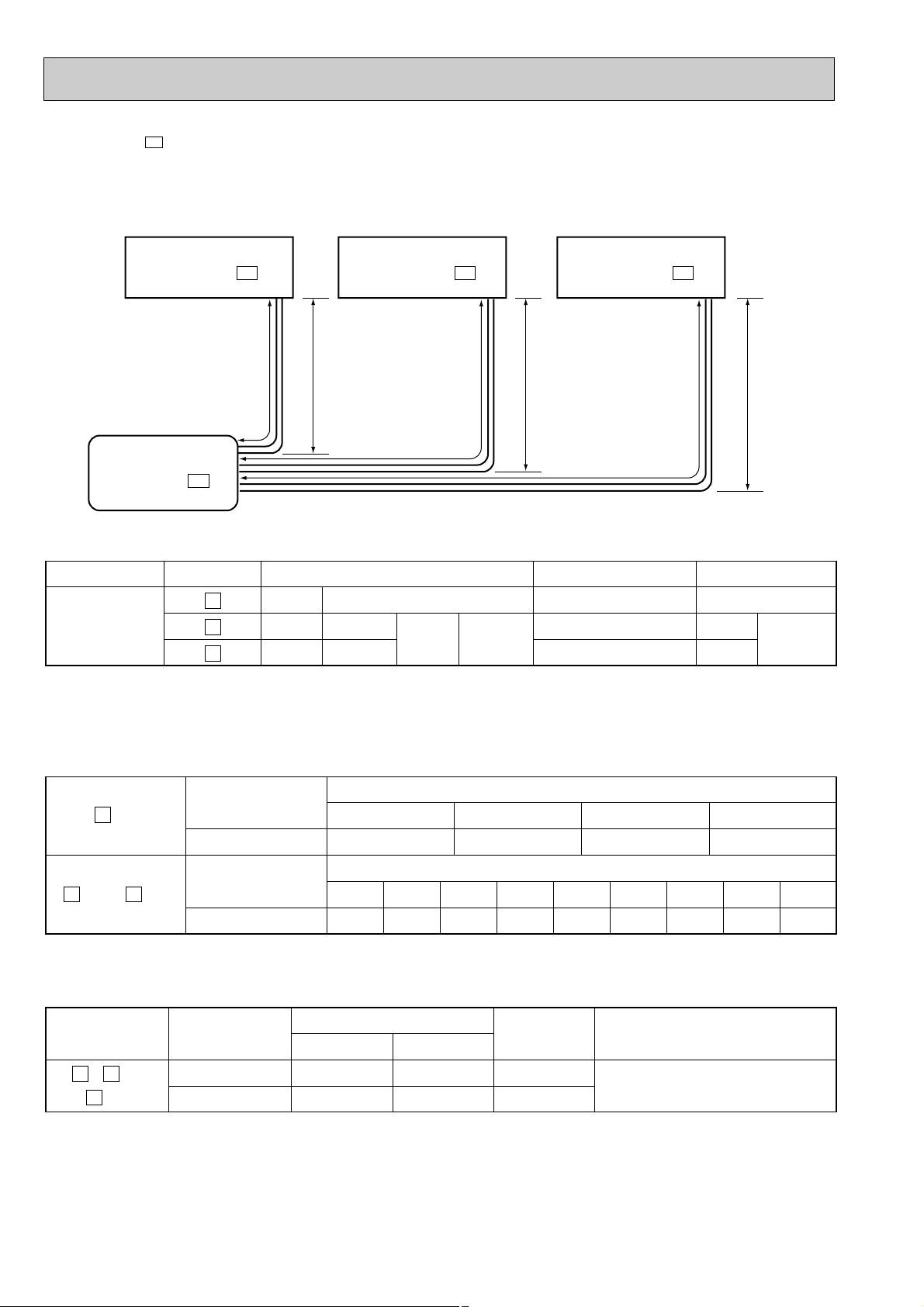
LA
Indoor unit A
MSX-09NV - E1
HL
B HLC
H
Indoor unit B
MSX-09NV - E1
Indoor unit C
MSX-09NV - E1
Outdoor unit
MUX-18NV - E1
MSX-09NV-
E1
MAX.REFRIGERANT PIPING LENGTH & MAX. HEIGHT DIFFERENCE
Max.
limits
UNIT No.
A
B
C
LA
LB
LC
Pipe length
10m
10m
10m
L
B
+
LC
Total
15m
Height difference (H)
5m
5m
5m
Note: The length of piping to individual units (A,B,C) should not exceed 10 meters.
If units B and C are linked, the maximum combined length of piping should not exceed 15 meters.
ADDITIONAL REFRIGERANT CHARGE (R-22:g)
Refrigerament piping length (one way)
Refrigerament piping length (one way,2 unit total)
9m
30
10m4511m
60
12m7513m9014m
A
unit
CB
unit + unit
Outdoor unit
precharged
750g
Outdoor unit
precharged
750g
7m 8m 9m 10m
0153045
7m
0
8m
15
PIPING PREPARATION
1Table below shows the specifications of pipes commercially available.
UNIT No.
BA
, and
C
unit
Pipe
For liquid
For gas
Outside diameter
mm inch
6.35 1/4
9.52 3/8
Insulation
thickness
6mm
6mm
Insulation material
Heat resisting foam plastic
0.045 specific gravity
No. of bends
10
10
10
105
Total
15
15m
120
2Ensure that the 2 refrigerant pipes are well insulated to prevent condensation.
3Refrigerant bending radius must be 10cm or more.
16
Page 17
MSX-09NV-
OUTDOOR UNITINDOOR UNIT
UNIT A
Indoor
heat
exchanger
Indoor coil
thermistor
RT12
Room
temperature
thermistor
RT11
UNIT B
Indoor
heat
exchanger
Outdoor
heat
exchanger
Indoor coil
thermistor
RT12
Room
temperature
thermistor
RT11
(option)
(With insulation)
Refrigerant pipe
{12.7 (1/2)
(option)
(With insulation)
Refrigerant pipe
{12.7 (1/2)
Flared connection
(option)
(With insulation)
Refrigerant pipe
{6.35 (1/4)
(option)
(With insulation)
Refrigerant pipe
{6.35 (1/4)
Flared connection
Stop valve
with service port
Solenoid valve
21R1
Solenoid valve
21RA
Solenoid valve
21R2
Capillary tube
{1.6 x 400
Capillary tube
{1.6 x 400
Capillary tube
Capillary tube
{1.8 x 260
{1.6 x 1,000
Compressor
Refrigerant flow
Stop valve
with service port
Stop
valve
Stop
valve
UNIT C
Indoor
heat
exchanger
Indoor coil
thermistor
RT12
Room
temperature
thermistor
RT11
UNIT D
Indoor
heat
exchanger
Indoor coil
thermistor
RT12
Room
temperature
thermistor
RT11
(option)
(With insulation)
Refrigerant pipe
{9.52 (3/8)
(option)
(With insulation)
Refrigerant pipe
{9.52 (3/8)
Flared connection
(option)
(With insulation)
Refrigerant pipe
{6.35 (1/4)
(option)
(With insulation)
Refrigerant pipe
{6.35 (1/4)
Flared connection
Stop valve
with service port
Solenoid valve
21R3
Solenoid valve
21RB
Solenoid valve
21R4
Capillary tube
{1.6 x 650
Capillary tube
{1.6 x 650
Capillary tube
Capillary tube
{1.6 x 400
{1.6 x 1,000
Compressor
Stop valve
with service port
Stop
valve
Stop
valve
MSX-12NV- E1
MSX-12NV- E1
MSX-09NV- E1
MSX-09NV- E1
MSX-12NV-
E1
E1
MUX-24NV-
E1
Unit : mm
17
Page 18

MSX-09NVMSX-12NV-
E1
E1
MAX.REFRIGERANT PIPING LENGTH & MAX. HEIGHT DIFFERENCE
Indoor unit A
MSX-12NV- E1
Indoor unit B
MSX-12NV- E1
Indoor unit C
MSX-09NV- E1
Indoor unit D
MSX-09NV- E1
Outdoor unit
MUX-24NV- E1
Max.
limits
UNIT No.
A
B
C
D
LA
LB
LC
LD
Pipe length
20m
20m
20m
20m
LA
+
LB
LC
+
LD
Total
30m
Total
30m
Height difference (H)
10m
10m
10m
10m
10
10
10
10
Note: The length of individual units (A,B,C,D) should not exceed 20 meters.
If units Aand B or C and D are linked, the maximum combined length of piping should not exceed 30 meters.
HLDHLCHLBHLA
No. of bends
Total
15
Total
15
ADDITIONAL REFRIGERANT CHARGE (R-22g)
UNIT No.
BA
unit + unit
DC
unit + unit
Outdoor unit
precharged
1150g
1150g
9m10m11m12m13m14m15m16m17m18m19m20m21m22m23m24m25m26m27m28m29m30
0 102030405060
0
10 20 30 40 50 60
Refrigerament piping length (one way, 2 unit total)
PIPING PREPARATION
UNIT No.
BA
and unit
DC
and unit
Pipe
For liquid
For gas
For liquid
For gas
Outside diameter
mm inch
6.35 1/4
12.7
6.35
9.52
1/2
1/4
3/8
m
70 80 90 100 110 120 130 140 150 160 170 180 190 200 210
70 80 90 100 110 120 130 140 150 160 170 180 190 200 210
Insulation
thickness
6mm
6mm
6mm
6mm
Insulation material
Heat resisting foam plastic
0.045 specific gravity
18
Page 19

Close
Open
Stop valve
Connection pipe
Gage manifold valve
Hexagonal
wrench
Vacuum pump
B unit
side
Service
port
Stop valve
Stop valve
Cap
Gas pipe
Liquid pipe
MUX-10NVMUX-24NV-
Connect the gage manifold valve and the vacuum pump to the service port of the stop valve on the
liquid pipe side of the outdoor unit.
Run the vacuum pump (Vacuumize for more than 15 minutes.) and at this time confirm that the pressure gage shows -0.1 MPa (-76cmHg).
Check the vacuum with the gage manifold valve, then close the gage manifold valve, and stop the
vacuum pump.
Leave it as is for one or two minutes. Make sure the pointer of the gage manifold valve remains in
the same position.
E1
E1
PURGING PROCEDURES
Connect the refrigerant pipes (both the liquid and gas
pipes) between the indoor and the outdoor units.
Remove the service port cap of the stop valve on the side of
the outdoor unit gas pipe. (The stop valve will not work in its
initial state fresh out of the factory (totally closed with cap on).)
MUX-10NV-
E1
MUX-24NV-
Remove the gage manifold valve quickly from the service port of the stop valve.
After refrigerant pipes are connected and evacuated, fully open all stop valves on
gas and liquid pipe sides.
Operating without fully opening lowers the performance and causes trouble.
MUX-10NV-
Pipe lenght
7m maximum
No gas charge is
needed.
E1
Pipe lenght
exceeding 7m
Charge the prescribed
amount of gas.
MUX-24NV-
Pipe lenght
9m maximum
No gas charge is
needed.
E1
Pressure gaugeCompound pressure gauge
Manifold valve
Handle Lo
Charge
hose
E1
Handle Hi
Vacuum
pump
Pipe lenght
exceeding 9m
Charge the prescribed
amount of gas.
Tighten the cap to the service port to obtain the initial status.
Retighten the cap.
Leak test
19
Page 20

Hexagonal
wrench
Cap
Service valves or
stop valves (4 pcs.)
Gage manifold valve
Connection pipe
Vacuum pump
Outdoor unit
Service valve
or stop valve
for UNIT
A
Service port
(check joint)
Liquid
Gas
A
UNIT
Gage manifold valve
Connection pipe
Vacuum pump
Outdoor unit
Service valve
or stop valve
for and
UNIT
B
C
B
C
Service port (check joint)
Liquid
Liquid
Gas
UNIT
UNIT
MUX-18NV-
E1
EVACUATION PROCEDURES
● Conduct air purging B unit and C unit, then Aunit.
● Conduct purging in the piping and indoor unit concurrently by using the service valve or stop valve of outdoor unit.
(1) Connect the refrigerant piping (both of the liquid pipe and gas pipe) between the indoor “ (and ) UNIT” and out-
CB
door units.
(2) Connect the gage manifold valve and the vacuum pump to the service port of service valve (lower (gas) side) for
“B(and C) UNIT”.
(3) Run the vacuum pump (Vacuumize for more than 15 minutes.) and at this time confirm that the pressure gage shows
-0.1MPa.
(4) Check the vacuum with the gage manifold valve, then close the gage manifold valve, and stop the vacuum pump.
(5) Leave it as is for one or two minutes. Make sure the pointer of the gage manifold valve remains in the same position.
(6) Remove the gage manifold valve quickly from the service port of the stop valve.
(7) Tighten the cap to the service port ot obtain the initial status.
(8) Connect the refrigerant piping (both of the liquid pipe and gas pipe) between the indoor “A UNIT” and outdoor units.
(9) Connect the gage manifold valve and the vacuum pump to the service port of stop valve (gas pipe side) for “A UNIT”.
(10) Run the vacuum pump (Vacuumize for more than 15 minutes.) and at this time confirm that the pressure gage shows
-0.1MPa.
(11) Check the vacuum with the gage manifold valve, then close the gage manifold valve, and stop the vacuum pump.
(12) Leave it as is for one or two minutes. Make sure the pointer of the gage manifold valve remains in the same position.
(13) Remove the gage manifold valve quickly from the service port of the stop valve.
(14) Tighten the cap to the service port to obtain the initial status.
● Turn valve rod of service valves or stop valves in counter clockwise direction it contacts the opposite side, that is until
the valves are fully opened.
● Fit back the cap of valve rod service valves or stop valves.
● Leak test
Using a gas leak detector or soap water, confirm that the refrigerant gas is not leaking from the flare nut connection.
CAUTION
● Connect refrigerant pipes of unit first, then connect unit, finally connect unit.(If you connect unit first, you
cannot connect unit.)
● Both refrigerant pipes and indoor and outdoor connecting wires are supposed to be connected properly in accordance
B
with unit references such as unit, unit, and unit.
20
CBA
AACB
Page 21

7
PERFORMANCE CURVES
The standard data contained in these specifications apply only to the operation of the air conditioner under normal conditions.
Since operating conditions vary according to the areas where these units are installed.
The following information has been provided to clarify the operating characteristics of the air conditioner under the conditions
indicated by the performance curve.
(1) GUARANTEED VOLTAGE
Voltage rating: ±10% (198~264V) 50Hz
(2) AIR FLOW
Air flow should be set at MAX.
(3) MAIN READINGS
(1) Indoor intake air wet-bulb temperature: °CWB
(2) Indoor discharge air wet-bulb temperature: °CWB
(3) Outdoor intake air dry-bulb temperature: °CWB
(4) Total input: W
Indoor air wet- bulb temperature difference on the left side of the chart on next page shows the difference between the
indoor intake air wet-bulb temperature and the indoor discharge air wet-bulb temperature for your reference at service.
How to measure the indoor air wet-bulb temperature difference
1. Attach at least 2 sets of wet-and dry-bulb thermometers to the indoor air intake as shown in the figure, and at least 2 sets
of wet-and dry-bulb thermometers to the indoor air outlet. The thermometers must be attached to the position where air
speed is high.
2. Attach at least 2 sets of dry-bulb thermometers to the outdoor air intake. Cover the thermometers to prevent direct rays of
the sun.
3. Make sure the air filter is cleaned.
4. Open windows and doors of room.
5. Press the EMERGENCY ON/OFF button to start the EMERGENCY operation.
6. When system stabilizes after more than15 minutes, measure temperature and take an average temperature.
7. 10 minutes later, measure temperature again and make sure the temperature does not change.
OUTDOOR UNITINDOOR UNIT
1.CAPACITY AND THE INPUT CURVES (ONE INDOOR UNIT WITH ONE OUTDOOR UNIT)
9.1
8.3
7.6
6.9
6.2
5.5
Indoor air WB temperature
difference (deg.)
8.9
8.2
7.4
6.7
6.0
5.4
10.1
9.3
8.4
7.6
6.8
6.1
1.4
10.4
9.4
8.5
7.6
6.8
MSX-10NV- E1
MSX-18NV- E1
MSX-24NV- E1
MSX-24NV- E1
(MSX-09NV- E1 )
(MSX-12NV- E1 )
21
Page 22

2.OUTDOOR LOW PRESSURE AND OUTDOOR UNIT CURRENT
COOL operation
① Both indoor and outdoor unit are under same temperature/humidity condition.
Dry-bulb temperature Relative humidity (%)
20
25
30
➁ Air flow should be set at MAX.
MUX-10NV-
E1
50
60
70
MUX-18NV-
MUX-24NV-
E1
E1
22
Page 23

8
MICROPROCESSOR CONTROL
Wireless remote controller
MSX-05NV- , MSX-09NV- , MSX-12NV-
Once the controls are set, the same operation mode can be
repeated by simply turning the OPERATE/STOP button ON.
Indoor unit receives the signal with a beep tone.
When the system turns off, 3-minute time delay will operate to
protect system from overload and compressor will not restart
for 3 minutes.
1. “I FEEL CONTROL” (h) OPERATION
E1E1E1
(1) Press OPERATE/STOP button on the remote con-
troller. OPERATION INDICATOR LAMP of the
indoor unit will turn on with a beep tone.
(2) Press OPERATION SELECT button to set “I FEEL
CONTROL”(h) Then a beep tone is heard.
(3) The operation mode is determined by the initial
room temperature at start-up of the operation.
Initial room temperature mode
.
more than 25:
13: to 25:
COOL mode of
I FELL CONTROL
DRY mode of
“I FELL CONTROL”
INDOOR UNIT DISPLAY SECTION
● Once the mode is fixed, the mode will not change
by room temperature afterwards.
● Under the ON-TIMER (w – ) operation, the mode is
determined according to the room temperature as the
operation starts.
● When the system is stopped with the
OPERATE/STOP button on the remote controller,
and restarted within 2 hours in “I FEEL CONTROL”
(h) mode, the system operates in previous mode
automatically regardless of the room temperature.
Example
Previous operation
COOL mode of
“I FEEL CONTROL”
or COOL mode
OFF ONON
2 hours
● When the system is restarted after 2 hours, the operation
mode is determined by the initial room temperature at
start-up of the operation.
Example
Previous operation
COOL mode of
“I FEEL CONTROL”
or COOL mode
OFFON
Restart
COOL mode of
“I FEEL CONTROL”
COOL or DRY mode of
“I FEEL CONTROL” that
determined by initital
room temperature startup of the operation.
2 hours
23
Page 24

(4) The initial set temperature is decided by the initial room temperature.
Model Initial room temperature Initial set temperrature
COOL mode of 26: or more 24:
“I FEEL ❈ 1
CONTROL” 26: or less
DRY mode of
“I FELL CONTROL” minus 2:
❈1 After the system restarts by the remote controller, the system operates with the previous set temperature regardless of
the initial set temperature.
The set temperature is calculated by the previous set temperature.
(5) TEMPERATURES buttons
In “I FEEL CONTROL” (h) mode, set temperature is decided by the microprocessor based on the room temperature.
In addition, set temperature is controlled by TOO WARM or TOO COOL buttons when you feel too cool or too warm.
Pressing the TOO WARM or TOO COOL button emits a beep tone.
13: to 25:
Initial room temperature
minus 2:
Initial room temperature
● Fuzzy control
When the TOO COOL or TOO WARM button is pressed, the microprocessor changes the set temperature, considering
the room temperature, the frequency of pressing TOO COOL or TOO WARM button and the user’s preference to heat or
cold. So this is called “Fuzzy control”, and works only in “I FEEL CONTROL” mode.
In DRY mode of “I FEEL CONTROL”, the set temperature doesn’t change.
▼ TOO
COOL… To raise the set temperature 1~2 degrees(°C)
▲ TOO
WARM … To lower the set temperature 1~2 degrees(°C)
24
Page 25

— COOL mode of “I FEEL CONTROL” —
ON
Compressor and
outdoor fan motor
Indoor fan motor
OFF
ON
ON
OFF
Run continuously in cooling mode
NOTE : Coil frost prevention during COOL mode of “I FEEL CONTROL”
There are two types of controls in coil frost prevention.
① Temperature control
When the indoor coil thermistor RT12 reads 4°C or below for 5 minutes, the coil frost prevention mode starts.
The compressor stops and the indoor fan operates at the set speed for 5 minutes.
After that, if RT12still reads below 4°C this mode prolonged until the RT12 reads over 4°C.
② Time control
When the three conditions below have been satisfied for 1 hour and 45 minutes, compressor stops for 3 minutes.
a. Compressor has been continuously operating.
b. Indoor fan speed is Lo or Me.
c. Room temperature is below 26°C.
When compressor turns off half way, the accumulated time is cancelled.
When compressor turns on again, time counting starts from the beginning.
When the indoor fan speed becomes Hi or the room temperature exceeds 26°C, time counting stops temporarily.
After, when the above conditions are satisfied again, time counting restarts.
The indoor fan operates at set speed.
● Indoor fan operates at the set speed by FAN CONTROL switch.
Followings are the fan speed in AUTO.
Room temperature minus set temperature : more than 2 ~ 4 degrees (°C)··············Hi
Room temperature minus set temperature : 1 ~ 4 degrees (°C) ·····························Me
Room temperature minus set temperature : less than 1 ~1.5 degrees (°C)·············Lo
—DRY mode of “I FEEL CONTROL”—
The system for dry operation uses the same refrigerant circuit as the cooling circuit.
The compressor and the indoor fan are controlled by the temperature and the microprocessor.
By such controls, indoor flow amounts will be reduced in order to lower humidity without much room temperature
decrease.
The operation of the compressor and indoor fan is as follows.
1. When the room temperature is 23°C or over:
Compressor operates by temperature control and time control.
① Set temperature is controlled to fall 2°C as initial set temperature.
② When the thermostat is ON, the compressor repeats 8 minutes ON and 3 minutes OFF.
When the thermostat is OFF, the compressor repeats 4 minutes OFF and 1 minute ON.
Indoor fan and outdoor fan operate in the same cycle as the compressor.
1 deg.
1.5 deg.
2 deg.
4 deg.
2. When the room temperature is under 23°C.
When the thermostat is ON, the compressor repeats 2 minutes ON and 3 minutes OFF.
When the thermostat is OFF, the compressor repeats 4 minutes OFF and 1 minute ON.
25
Page 26

Operation time chart
Example
1st ON
ON
Thermostat
Indoor fan
Outdoor fan
compressor
8 min. 1 min.3 min.
NOTE ● Coil frost prevention during DRY mode of “I FEEL CONTROL”
The operation is same as coil frost prevention during COOL mode of “I FEEL CONTROL” excepting the
indoor fan is OFF.
● Coil frost becomes the fan speed Lo during the indoor fan is OFF.
(Because the coil frost prevention is priority.)
2. COOL (
(1) Press OPERATE/STOP button.
(2) Select COOL mode.
(3) Set the TEMPERATURES button.
3. DRY (
(1) Press OPERATE/STOP button.
(2) Select DRY mode.
(3) The microprocessor reads the room temper-
(4) DRY operation will not work when the room
(5) When DRY operation works, the fan speed is
ff
) OPERATION
OPERATION INDICATOR of the indoor unit
turns on with a beep tone.
(TOO WARM or TOO COOL button)
The setting range is 16 ~ 31°C
✻ Indoor fan continues to operate regardless
of thermostat’s OFF-ON
✻ Coil frost prevention is same as COOL
mode of “I FEEL CONTROL”
ee
) OPERATION
OPERATION INDICATOR of the indoor unit
turns on with a beep tone.
ature and determines the set temperature.
Set temperature is as shown in the right
chart.
Thermostat (SET TEMP.)is not work.
The other operations are same as DRY
mode of “I FEEL CONTROL”.
temperature is 13°C or below.
lower than cool operation.
OFF
OFF
OFF
OFF
OFF
ONONON
ONONON
26
Page 27

4.FAN OPERATION
(1)Press OPERATION/STOP button.
(2)Select FAN mode.
(3)Select the desired fan speed.When AUTO,it becomes Lo.(Only DRY operation.)
Only indoor fan operates.Outdoor unit does not operate.
5. FAN MOTOR CONTROL
(1) Rotational frequency feedback control
The indoor fan motor is equipped with a rotational frequency sensor, and outputs signal to the microprocessor to feedback
the rotational frequency. Comparing the current rotational frequency with the target rotational frequency (Hi,Me.Lo) the
microprocessor controls SR11 and adjusts fan motor electric current to make the current rotational frequency close to the
target rotational frequency. With this control, when the fan speed is switched, the rotational frequency changes smootly.
Rotational frequency
Hi
Me
Lo
New control
Hi
time
(2) Fan motor lock-up protection
When the rotational frequency feedback signal is not output for 12 seconds, (or when the microprocessor cannot detect the
signal for 12 seconds) the fan motor is regarded locked-up. Then the electric current to the fan motor is shut off. 3 minutes
later, the electric current is applied to the fan motor again. During the fan motor lock-up, the operation indicator flashes to
show the fan motor abnormality. (See page 32.)
6. AUTO VANE OPERATION
(1) Vane motor drive
MSX-N series is equipped with a stepping motor for the vane. The rotating direction, speed, and angle of the motor are
controlled by plus signals (approx. 12V) transmitted from indoor microprocessor.
(2) The auto vane angle changes as follows by pressing the VANE CONTROL “” button.
AUTO 1
2 3
4 5
Horizontal Middle Downward
(3) Positioning
The vane is once pressed to the vane stopper below to confirm the standard position and then set to the desired angle.
The positioning is decided as follows.
(a) When the operate button is pushed. (POWER ON)
(b) When th stop button is pushed. (POWER OFF)
(c) When the vane control change AUTO to MANUAL.
(d) When the SWING is finished.
(e) When the test run starts.
(f ) When the power supply is ON.
27
Page 28

(4) VANE AUTO ( ) mode
In VANE AUTO mode, the microprocessor automatically determines the vane angle and operation to make the optimum
room-temperature distribution.
① In COOL and DRY operation
Vane angle is fixed to Angle 1.
➁ In FAN operation
Vane angle is fixed to Angle 4.
(5) Dew prevention
During COOL or DRY operation with the vane angle at Angle 4 or 5 when the compressor cumulative operation the
exceeds 1 hour, the vane angle automatically changes to Angle 1 for dew prevention.
(6) SWING MODE ( )
By pressing the SWING button “” vane swings vertically. The remote controller displays “” SWING mode is can-
celled when the SWING button is pressed again or the operation stops or changes to other mode or VANE button is
pressed.
7. SLEEP MODE ()
• When the sleep button “” is pressed, the indoor fan speed drops and the air flow sound from the indoor unit is
decrecsed.
• The indications of the remote controller are “” and “”.
• When the button is pressed during the SLEEP mode operation, the SLEEP made is released.
8. TIMER OPERATION
1. How to set the timer.
(1) Press OPERATE/STOP button to start the air conditioner.
(2) Check that the current time is set correctly.
NOTE : Timer operation will not work without setting the current time. Initially “AM0:00” blinks at the current time display
of TIMER MONITOR so set the current time, correctly with CLOCKSETTING button.
(3) Press TIMER CONTROL button to select the operation.
“w –
” button... AUTO START operation (ON timer) Ascertain the OPERATION INDICATOR on the indoor unit lights.
l
“w – O” button... AUTO STOP operation (OFF timer)
(4) Press HR. and MIN. button to set the timer. Time setting is 10-minute units.
HR. and MIN, button will work when “w – l” or “w – O” mark is flashing.
These marks disappear in 30 seconds.
When setting the ON timer, check that OPERATION INDICATOR of the indoor unit lights.
NOTE1 : Be sure to place the remote controller at the position where its signal can reach the air conditioner even during
TIMER operation, or the set time may deviate within the range of about 10 minutes.
NOTE2 : Reset the timer in the following cases, or the set time may deviate and other malfunctions may occur.
● A power failure occurs.
● The circuit breaker functions.
2. CANCEL
Timer setting can be cancelled with the TIMER CONTROL buttons. (“w – l” or “w – O”)
To cancel the ON timer, press the “w – l” button.
To cancel the OFF timer, press the “w – O” button.
Timer is cancelled and the display of set time disappears.
28
Page 29

PROGRAM TIMER
● The OFF timer and ON timer can be used in combination.
● ”” display shows the order of the OFF timer and ON timer operation order.
(Example 1) The current time is 8:00 PM.
The unit turns off at 11:00 PM, and on at 6:00 AM.
NOTE : TIMER setting will be cancelled by power failure or breaker functioning.
(Example 2) The current time is 11:00 AM.
The unit turns on at 5:00 PM, and off at 9:00 PM.
9. EMERGENCY-TEST OPERATION
When the remote controller is missing, has failed or the batteries run down, press the EMERGENCY ON/OFF button on the
front of the indoor unit. The unit will start and the OPERATION INDICATOR will light.
The first 30 minutes of operation will be the test run operation. This operation is for servicing. The indoor fan runs at high
speed and the system is in continuous operation. The thermostat is ON and the timer is reset to normal.
After 30 minutes of test run operation the system shifts to emergency run operation with a set temperature of 24°C
The fan shifts to MED speed.
This operation continues until the EMERGENCY RUN ON/OFF button is pressed or a button on the remote controller is
pressed, then normal operation will start.
The coil frost prevention circuit operates in this mode.
In the test run or emergency operation, auto vane operates in AUTO mode with the set temperature 24°C.
NOTE : Do not press the EMERGENCY ON/OFF button during normal operation.
Push 1 - time
<Coolong>
2 - times
<Stop>
29
Page 30

9
SERVICE FUNCTIONS
1. TIMER SHORT MODE
For service, set time can be shortened by short circuit of JPG and JPS on the electronics control P.C. board.
The time will be shortened as follows.
3-minute delay : 3-minute ➔ 3-second.
AUTO START : 1 hour ➔ 1-minutes
AUTO STOP : 1 hour ➔ 1-minutes
Short the connector during the timer mode.
}
2. P.C. BOARD MODIFICATION FOR INDIVIDUAL OPERATION
A maximum of 4 indoor units with wireless remote controllers can be used in a room.
In this case, to operate each indoor unit individually by each remote controller, P.C. boards of remote controller must be
modified according to the number of the indoor unit.
Remove batteries before modification.
The board has a print as shown below :
<The reset button can be located on the rear side.>
(1)How to modify the remote controller P.C. board
MSX-05NV- ,MSX-09NV-
The P.C.board has the print “J10” and “J20”.Jumper wires are mounted to each “J10” and “J20”.Replace J20 and J10 with
J21 and J11 according to the number of indoor unitw as shown in Table 1.
After modification,push the reset button near the batteries.
Table.1
No. 1 unit
No. 2 unit
No. 3 unit
No. 4 unit
Note : At power supply failure or installation, indoor unit deletes the memory about remote controller.
When the power supply is turned on and indoor unit receives the first signals from the remote controller, the remote
controller number is designated as the indoor unit number.
Therefore at and after the second time indoor unit accepts the remote controller of the initial setting number.
At setting-error, turn the power supply off to cancel the individual operation and then turn the power supply on to restart
the setting
1 unit operation
No modification
E1E1
NOTE : For remodeling, take out the batteries at first.
After finish remodeling, put back the batteries then push the RESET button.
2 unit operation
Same as at left
-
-
-
Replace J10 with J11
-
-
3 unit operation
Same as at left
Same as at left
Replace J20 with J21
4 unit operation
Same as at left
Same as at left
Same as at left
-
Replace J10 with J11
Replace J20 with J21
<The reset button can be located on the front side.>
(2)How to modify the remote controller P.C. board
MSX-05NV- (Product number 7000501T~) ,MSX-09NV- (Product number 7000701T~) ,MSX-12NV-
E1E1E1
NOTE : For remodeling, take out the
batteries at first.
After finish remodeling, put
back the batteries then
push the RESET button.
The P.C.board has the print “J1” and “J2”.Jumper wires are mounted to each “J1” and “J2”.Cut J1 and J2 according to the
number of indoor unitw as shown in Table 1.
After modification,push the reset button near the batteries.
Table.1
No. 1 unit
No. 2 unit
No. 3 unit
No. 4 unit
Note : At power supply failure or installation, indoor unit deletes the memory about remote controller.
When the power supply is turned on and indoor unit receives the first signals from the remote controller, the remote
controller number is designated as the indoor unit number.
Therefore at and after the second time indoor unit accepts the remote controller of the initial setting number.
At setting-error, turn the power supply off to cancel the individual operation and then turn the power supply on restart
the setting
30
1 unit operation
No modification
-
-
-
2 unit operation
Same as at left
Cut J1
-
-
3 unit operation
Same as at left
Cut J2
-
4 unit operation
Same as at left
Same as at left
Same as at left
Cut J1
Cut J2
Page 31

10
TROUBLESHOOTING
MSX-05NV- , MSX-09NV- , MSX-12NV-
10-1 Cautions on troubleshooting
10-1-1 Before troubleshooting, check the followings:
1) Check the power supply voltage.
2) Check the indoor/outdoor connecting wire for mis-wiring.
10-1-2 Take care the followings during servicing.
1) Be sure to unplug the power cord before removing the front panel, the cabinet, the top panel, and the P.C. boards.
2) When removing the P.C. board, hold the edge of the board with care NOT to apply stress on the components.
3) When connecting or disconnecting the connectors, hold the housing of the connector. DO NOT pull the lead wires.
10-1-3 Troubleshooting procedure
1) First, check if the POWER LAMP on the indoor unit is flashing to indicate an abnormality. To make sure, check the
abnormality indication for 2 or 3 times before starting service work.
2) If the P.C. board is supposed to be defective, check the copper foil pattern for disconnection and the components for
bursting and discoloration.
3) When troubleshooting, refer to the flow chart and the check table on page 28.
10-14 How to replace batteries
Weak batteries may cause the remote controller malfunction.
In this case, the remote controller can not be repaired only by the battery replacement. To operate the remote controller normally, discharge the remote controller in the following order.
This remote controller has the reset button. After refilling new batteries, press the reset button with tip end of ball point
pen or the like, and then use the remote controller.
E1E1E1
31
Page 32

10-2 Instruction of troubleshooting
Start
Indoor unit operates. Outdoor unit
doesn’t operate.
Outdoor unit
operates in
only Test
Run mode.
Check room
temperature
thermistor.
Outdoor unit
doesn’t operate even in
Test Run
mode.
Refer to
DD
“Check of
outdoor unit”
on page 31.
Indoor unit
dosen’t receive
the signal from
remote
controller.
Refer to
BB
”Check of
receiver P.C.
board” on page
30.
Indoor unit operation
monitor lamp is flashing
2-time flash
2.5-second OFF
3-time flash
2.5-second OFF
Cause:Indoor unit
2-time-Room temperature/Indoor coil thermistor trouble.
3-times-Indoor fan motor trouble
Check indoor coil
thermistor. Refer
to“Test point diagram and voltage”
on page 32.
Refer to
AA
“Check of indoor
fan motor” on
page 30.
Indoor unit doesn’t
receive the signal from
remote controller.
Also, operation monitor
lamp doesn’t flash, when
the emergency operation
switch is pressed.
Refer to CC“Check of
indoor electric control
P.C. board” on page 31.
Check room temperature.
Refer to“Test point diagram and voltage” on
page 32.
10-2-1 troubleshooting check table
❈ Before taking measures make sure that the symptom reappears, for accurate troubleshooting.
Self check table
Abnormal
NO.
1
2
point
Indoor coil
thermistor
Room
temperature thermistor
Indoor fan
motor
2-time flash
2.5-second OFF
3-time flash
Indication
2.5-second OFF
Symptom
Outdoor unit
does not run.
Indoor fan
repeats 12 seconds ON and 3
minutes OFF.
When the indoor
fan breaks, the
fan keeps stopping.
Detect method
Detects Indoor coil/room temperature thermistor short or
open circuit every 2 seconds
during operation.
When rotational frequency
feedback signal is not emit
during 12-second indoor fan
operation
● Check thermistor calibretion
● Reconnect connector
● Check indoor borad
● Disconnect connector CN211 and then
check connector CN121 22- 33to make
sure rotational frequency feedback signal
of 1.5V or over exists.
● Check indoor electronic control P.C.
board.
● Check indoor fan motor
● Reconnect conector
Repair
32
Page 33

BLK
RED
WHT
P
10-2-2 Trouble criterion of main parts
1
2
3
RED
BLK
YLW
GRY
BRN
WHITE
1
2
3
Part name
Room
temperature
thermistor
Indoor coil
thermistor
Compressor
Indoor fan
motor
Check method and criterion
Measure the resistance with a tester.
(Part temperature 10°C ~ 30°C)
Normal
8kΩ ~ 20kΩ
Opened or short-circuited
Abnormal
Measure the resistance between the terminals with a tester.
(Coil wiring temperature-10°C ~ 40°C)
Normal
C-R
C-S
MUX-10NVMUX-18NV-
KH-134VLL
4.1 ~ 5.0Ω
7.2 ~ 8.8Ω
E1
E1
RH-174VGH
2.9 ~ 3.6Ω
5.1 ~ 6.3Ω
MUX-24NV-
RH-231VHA
1.9 ~ 2.3Ω
3.4 ~ 4.2Ω
E1
Abnormal
Opened or
short-circuited
Measure the resistance between the terminals with a tester.
(Coil wiring temperature10°C ~ 30°C)
WHT-BLK
Motor part
BLK-RED
Normal
280 ~ 303Ω
313 ~ 336Ω
Abnormal
Opened or
short-circuited
Measure the voltage Power ON.
BRN-YLW
Sensor part
YLW-GRY
Normal
4.5 ~ 5.5Ω
(When fan revolved one time)
0V➔5V➔0V
(Approx.)
Abnormal
Remain
0V or 5V
Figure
Measure the resistance between the terminals with a tester.
(Coil wiring temperature -10°C ~ 40°C)
Outdoor fan
motor
Solenoid coil
21R, 21RA,
( )
21RB
Solenoid coil
21R1, 21R2,
()
21R3, 21R4
WHT-BLK
BLK-RED
BLK-YLW
YLW-RED
Measure the resistance with a tester. (Part temperature -10°C ~ 40°C)
Measure the resistance with a tester. (Part temperature -10°C ~ 40°C)
Measure the resistance between the terminals with a tester.
(Part temperature10°C ~ 30°C)
Vane motor
MUX-10NV-
287 ~ 351Ω
347 ~ 424Ω
Normal
602 ~ 749Ω
Normal
1498 ~ 1834Ω
Normal
282 ~ 305Ω
Normal
E1
MUX-18NV-
103 ~ 127Ω
57 ~ 71Ω
43 ~ 54Ω
Abnormal
Opened or short-circuited
Abnormal
Opened or short-circuited
Abnormal
Opened or short-circuited
E1
MUX-24NV-
125 ~ 153Ω
119 ~ 146Ω
E1
Abnormal
Opened or
short-circuited
MUX-10NV
MUX-18NV
BLK
MUX-24NV
P
BLK
REDYLW ORN
RED ORN
P
WHT
WHT
33
Page 34

A
Check of indoor fan motor
Inodoor fan does not operate.
Are lead wires connected?
Reconnect
lead wires
Disconnect lead wires from connector CN211 on indoor control P.C. board.
Measure resistance between lead wires No.1 and No.3 and then No.2 and No.3.
B
Check of receiver P.C. board
Turn OFF power supply.
Check connector CN211 visually.
Is resistance 0 (short circuit) or ∞ (open circuit)?
Yes ( 0 or ∞ )
Repair indoor fan motor.
NoYesNo
Is soldered point normal?
Yes
Resolder it.
Replace indoor electronic control
P.C. board.
No
(others)
Indoor unit operates by pressing the emergency ON/OFF switch, but does not operate with the remote controller.
Check the model name of remote
controller.
Is.LCD display on remote controller
visible?
Yes
Remove batteries and then set them
back. Check if the unit operates with
remote controller.
Does the unit operate with remote
controller?
Yes
OK
No
(not clear)
No
Replace batteries.(see page 27.)
Turn a radio to AM and press switch on
remote controller.
Is noise heard from radio?
Yes
Are there any fluorescent lights of
inverter or rapid-start type within
the range of 1m?
No
Measure the voltage between control board connector LD101 No.2 and JPG.
when remote controller button is pressed.
No
Yes
Replace remote controller
● Re-install the unit away from lights.
● Attach a filter on receiving part.
34
Is the voltage approx. 4V DC?
No(5V or OV DC)
Replace the receiver
Yes
Replace indoor electronic control
P.C. board.
Page 35

C
Check
of indoor electronic control P.C. board
The unit doesn’t operate with
the remote controller.
Also, the operation indicator
doesn’t light up by pressing the
emergency ON/OFF switch.
Replace fuse.
Yes
Trouble of indoor electronic control P.C.
board.
No
1.Pull out power supply
cord.
2.Measure resistance
between CN201 on
electronic control
P.C. board and on
the terminal block with
a tester.
No
CN201
11 33
Check both “parts side”and “pattern
side ✻ of indoor electronic control P.C.
board visually
D
Check of outdoor unit
Is fuse(F11)blown?
Be sure to check both fuse
and varistor in any case.
Is varistor(NR11)burnt?
Yes
Replace varistor.
Compressor and outdoor fan do not operate.(Only indoor fan operates.)
Yes
Is there resistance
1
N
L
N
(Approx.0Ω)
No
Trouble of fuse(F12)
Terminal
block
Start
Press EMERGENCY ON/OFF button.
3-minute time delay works.
Test mode operates for 30 minutes.
Check voltage to terminal block of outdoor unit. Is
there 220-240V AC to terminal block between LL-
NN
?
Yes
Check voltage to terminal block of indoor unit. Is
there DC12V to terminal block between 22- 11?
Yes
Check the fuse (F12-F14).Is it cut?
No
Check the outdoor fan motor , compressor , relya ,
and wiring.
No
Check the connection of indoor and outdoor
and the power supply.
No
Check continuity of indoor and outdoor unit connection.
Yes
Replace the fuse.
35
Page 36

TEST POINT DIAGRAM AND VOLTAGE
MSX-05NV- , MSX-09NV- , MSX-12NVIndoor electronic control P.C. board
E1E1E1
CN201 No.1
Varistor(NR11)
Fuse AC250V 3.15A
Room temperature
thermistor (RT11)
Indoor coil
thermistor (RT12)
Timer short mode
point
Room temperature thermistor (RT11)
Indoor coil thermistor (RT12)
36
Page 37

11
DISASSEMBLY INSTRUCTIONS
NOTE:
❈ on the wiring diagram shows the terminals with a lock mechanism, so it
cannot be removed when you pull the lead wire. Be sure to pull the wire by
pushing the locking lever (projected part) of the terminal with a finger.
① Slide the sleeve.
➁ Pull the wire while pushing
the locking lever.
11-1 MSX-05NV- , MSX-09NV- , MSX-12NV- INDOOR UNIT
E1E1E1
OPERATING PROCEDURE
1. Removing the front panel.
(1) Remove the screws caps of the front panel.
Remove the screws.
(2) Pull the panel bottom to your side slightly and unhook the
catches at the top.
2. Removing the electronic control P.C. board and the
display P.C. board.
(1) Remove the front panel. (Refer to 1)
(2) Remove the screw of the electrical cover.
Remove the electrical cover.
(3) Disconnect the room temperature thermistor and the con-
nector from the indoor coil thermistor.
(4) Remove the terminal cover.
Remove the screw of the terminal block.
(5) Disconnect all the connectors on the electronic control P.C.
board.
(6) Disconnect the white lead wire and the black lead wire from
52C relay.
(7) Remove the electronic control P.C. board and the display
P.C. board.
Photo 1
Front panel
Screw
Photo 2
PHOTOS
Room temperature
thermistor connector
Indoor electronic
control P.C.
board
Terminal block
cover
Terminal block
cover screw
37
Page 38

OPERATING PROCEDURE PHOTOS
3. Removing the electrical box.
(1) Remove the front panel. (Refer to 1)
(2) Remove the electrical cover.
(3) Disconnect the connector of the indoor coil thermistor.
(4) Disconnect the motor connector (CN211) and the vane
motor connector (CN151) on the electronic control P.C.
board.
(5) Unhook the catches (both upper and lower), remove the
electronic box.
4. Removing the vane motor.
(1) Remove the front panel.(Refer to 1)
(2) Remove the screw of the vane motor, disconnect the con-
nector.
(3) Remove the vane motor.
5. Removing the line flow fan and the indoor fan
motor.
(1) Remove the front panel. (Refer to 1)
(2) Disconnect the connector from the vane motor.
(3) Pull out the drain hose from the nozzle assembly, remove
the nozzle assembly.
(4) Lifting the left side of the heat exchanger, remove the elec-
trical box.
(5) Remove the fixture of the fan motor.
(6) Remove the line flow fan and the fan motor.
Photo 3
Photo 4
Vane motor screw
Drain hose
Vane motor
38
Fan motor
catches
Fan motor
fixture
Indoor coil
termistor
Page 39

11-2 MUX-10NV - OUTDOOR UNIT
E1
OPERATING PROCEDURE PHOTOS
1. Removing the cabinet.
(1) Remove the screws fixing the service panel.
(2) Remove the screw fixing the side panel.
(3) Remove the service panel.
(4) Remove the side panel.
(5) Remove the cabinet.
Photo 1
Screws
Photo 2
Cabinet
Service
panel
Screws
2. Removing the propeller.
(1) Remove the cabinet.
(2) Remove the propeller nut.
(3) Remove the propeller.
Note : Loosen the propeller in the rotating direction for removal.
When setting the propeller, align the motor-shaft cut
section.
3. Removing the outdoor fan motor.
(1) Remove the cabinet. (Refer to 1.)
(2) Remove the propeller.(Refer to 2.)
(3) Remove the lead clamps and disconnect the outdoor fan
motor connector.
(4) Remove outdoor fan motor set screws.
(5) Remove the outdoor fan motor.
Photo 3
Propeller
Propeller
Photo 4
Outdoor fan motor
Outdoor fan motor
set screws
39
Page 40

OPERATING PROCEDURE PHOTOS
4. Removing the compressor.
(1) Remove the cabinet. (Refer to 1.)
(2) Remove the terminal cover.
(3) Pull out lead from the compressor terminal, then remove
the thermal protector.
(4) Remove the suction pipe welded section and discharge
pipe welded section using a burner.
Pull out when the welding melts.
(5) Remove the sound proof felt.
(6) Remove the compressor 3 set nuts.
(7) Remove the compressor.
Note :
● Before using the welder, confirm that the pressure gauge is
0 kg/cm
● When using the welder, leave the service port open and release
the pressure to avoid expansion by heat.
2
.
Photo 5
Discharge
pipe
Suction
pipe
Sound proof felt
40
Page 41

11-3 MUX-18NV - OUTDOOR UNIT
E1
OPERATING PROCEDURE PHOTOS
1.Removing the cabinet.
(1) Remove the screws fixing the service panel.
(2) Remove the screw fixing the side panel.
(3) Remove the service panel.
(4) Remove the side panel.
(5) Remove the cabinet.
Photo 1
Side
panel
Side panel
set screw
Cabinet
Service panel
Service panel
set screw
2. Removing the propeller.
(1) Remove the cabinet.
(2) Remove the propeller nut.
(3) Remove the propeller.
Note: Loosen the propeller in the rotating direction for removal.
When setting the propeller, align the motor-shaft cut section.
3.Removing the outdoor fan motor.
(1) Remove the cabinet.(Refer to 1.)
(2) Remove the propeller.(Refer to 2.)
(3) Remove the lead clamps and disconnect the outdoor fan
motor connector.
(4) Remove outdoor fan motor set screws.
(5) Remove the outdoor fan motor.
Photo 2
Photo 3
Propeller
Propeller nut
Fan motor
Outdoor fan motor
set screws
41
Page 42

OPERATING PROCEDURE
4. Removing the compressor.
(1) Remove the cabinet.(Refer to 1.)
(2) Remove the terminal cover.
(3) Pull out lead from the compressor terminal,then remove
the terminal overcurrent relay.
(4) Remove the suction pipe welded section and discharge
pipe welded section using a burner.
Pull out when the welding melts.
(5) Remove the sound proof felt.
(6) Remove the compressor 3 set nuts.
(7) Remove the compressor.
NOTE:
● Before using the welder, confirm that the pressure gauge is
0 Kg/cm
● When using the welder, leave the service port open and
release the pressure to avoid expansion by heat.
2
.
PHOTOS
Photo 4
Suction pipe
5. Removing the compressor.
(1) Remove the cabinet.(Refer to 1.)
(2) Remove the terminal cover.
(3) Pull out lead from the compressor terminal,then remove
the terminal overcurrent relay.
(4) Remove the screws fixing the back panel.
(5) Remove the suction pipe welded section and discharge
pipe welded section using a burner.
Pull out when the welding melts.
(6) Remove the sound proof felt.
(7) Remove the compressor 3 set nuts.
(8) Remove the compressor.
Discharge pipe
Sound proof felt
42
Page 43

11-4 MUX-24NV- OUTDOOR UNIT
E1
OPERATING PROCEDURE PHOTOS
1.Removing the cabinet.
(1) Remove the screws fixing the service panel.
(2) Remove the screw fixing the top panel.
(3) Remove the service panel.
(4) Remove the top panel.
(5) Remove the screws fixing the front panel.
(6) Remove the front panel.
(7) Remove the screws fixing the outer nozzle.
(8) Remove the outer nozzle.
Photo 1
Screws
Front panel
Top panel
Service panel
set
screws
Photo 2
Rear panel
Rear panel
set
screws
Photo 3
Top panel
set screws
Screws Screws
43
Page 44

OPERATING PROCEDURE PHOTOS
2. Removing the relay panel.
(1) Remove the cabinet. (Refer to 1)
(2) Disconnect the following connectors.
.
Compressor (MC1,MC2)
.
Outdoor fan motor
.
Solenoid coil (21R1,21R2,21R3,21R4,21RA,21RB)
3. Removing the propeller.
(1) Remove the cabinet.
(2) Remove the propeller nut.
(3) Remove the propeller.
Note : Loosen the propeller in the rotating direction for removal.
When setting the propeller, align the motor-shaft cut
section.
Photo 4
Compressor connector
(MC1,MC2)
Photo 5
Solenoid coil connector
(21RA,21RB)
Screws
Solenoid coil connector
(21R1,21R2,21R3,21R4)
4. Removing the outdoor fan motor.
(1) Remove the cabinet. (Refer to 1)
(2) Remove the propeller. (Refer to 3)
(3) Disconnect the connector remove the clamp of outdoor fan
motor lead wire.
(4) Remove the screws fixing the outdoor fan motor.
44
Propeller
Propeller nut
Photo 6
Clamp
Outdoor
fan
motor
Outdoor fan motor
set screws
Page 45

OPERATING PROCEDURE PHOTOS
5. Removing the compressor. (A,B)
(1) Remove the cabinet. (Refer to 1)
(2) Remove the relay panel. (Refer to 2)
(3) Remove the terminal cover.
(4) Pull out lead from the compressor.
(5) Remove the suction pipe welded section and discharge
pipe welded section using a burner. Pull out when the
welding melts.
(6) Remove the sound proof felt.
(7) Remove the compressor set nuts.
(8) Remove the compressor.
6. Removing the compressor. (C,D)
(1) Remove the cabinet. (Refer to 1)
(2) Remove the relay panel. (Refer to 2)
(3) Remove the screws fixing rear panel. (Refer to photo 2)
(4) Remove the rear panel.
(5) Remove the terminal cover.
(6) Pull out lead from the compressor.
(7) Remove the suction pipe welded section and discharge
pipe welded section using a burner. Pull out when the
welding melts.
(8) Remove the sound proof felt.
(9) Remove the compressor set nuts.
(10) Remove the compressor.
Photo 7
Terminal cover
Sound proof felt Suction pipe Discharge pipe
45
Page 46

12
No.
Parts No. Parts Name Remarks
MSX-12NV-
E1
(WH)
Symbol
in Wiring
Diagram
1
2
3
4
5
6
E02 154 000
E02 157 000
E02 151 010
E02 164 100
E02 151 234
E02 160 234
E02 151 970
E02 151 970
FRONT PANEL
FRONT PANEL
GRILLE
AIR FILTER
BOX
BOX
INSTALLATION PLATE
SCREW CAP
1
1
2
1
1
2
MSX-05/09NV-
E1
(WH)
1
1
2
1
1
2
1PC/SET
2PCS/SET
Q'ty / unit
PARTS LIST
INDOOR UNIT
STRUCTURAL PARTS
MSX-05NV - (WH)
MSX-09NV - (WH)
MSX-12NV - (WH)
6
E1
E1
E1
1
5
4
2
Optional parts
3
46
Page 47

INDOOR UNIT
No.
Parts No. Parts Name Remarks
Q'ty / unit
MSX-05/09NV-
E1
(WH)
MSX-12NV-
E1
(WH)
Symbol
in Wiring
Diagram
Part number that are circled not shown in the figure.
1
2
3
4
5
6
7
8
9
10
11
12
13
14
15
16
17
18
19
E02 199 235
E02 166 235
E02 166 040
E02 141 702
E02 151 303
E02 151 300
E02 151 505
E02 151 302
E02 151 509
E02 151 308
E02 151 307
E02 211 375
E02 211 450
E02 281 450
E02 152 395
E02 127 382
E02 164 081
E02 151 350
E02 085 385
E02 001 504
E02 199 520
NOZZLE(WH)
NOZZLE(WH)
VANE(WH)
DRAIN HOSE
VANE MOTOR
INDOOR FAN MOTOR
RUBBER MOUNT
LINE FLOW FAN
BEARING MOUNT
ROOM TEMPERATURE THERMISTOR
INDOOR COIL THERMISTOR
TERMINAL BLOCK
ELECTRONIC CONTROL P.C.BOARD
ELECTRONIC CONTROL P.C.BOARD
POWER SUPPLY CORD
FUSE
ELECTRICAL BOX
INDOOR FAN CAPACITOR
VARISTOR
SLEEVE BEARING
FAN GUARD
1
1
1
1
1
2
1
1
1
1
1
1
1
1
1
1
1
1
1
1
1
1
1
1
1
1
1
1
1
1
1
1
1
1
1
1
1
1
RC4V19 2PES/SET
3.15A
1.5µF/440VAC
MV
MF
RT11
RT12
TB
F11
C11
NR11
ELECTRICAL PARTS
MSX-05NV - (WH)
MSX-09NV - (WH)
MSX-12NV - (WH)
E1
E1
E1
8
18
3
9
10
15
7
11
6
5
1
2
4
13
12
47
Page 48

No.
Parts No. Parts Name Remarks
MSX-05/09NV-
E1
(WH)
Symbol
in Wiring
Diagram
Q'ty / unit
1
2
3
E02 151 620
E02 151 666
E02 155 666
E02 151 667
INDOOR HEAT EXCHANGER
UNION(GAS)
UNION(GAS)
UNION(LIQUID)
1
1
1
{ 9.52
{ 12.7
{ 6.35
MSX-12NV-
E1
(WH)
1
1
1
INDOOR UNIT
HEAT EXCHANGER
MSX-05NV - (WH)
MSX-09NV - (WH)
MSX-12NV - (WH)
E1
E1
E1
1
48
3
2
Page 49

REMOTE CONTROLLER & ACCESSORY PARTS
MSX-05NV - (WH)
MSX-09NV - (WH)
MSX-12NV - (WH)
E1
E1
E1
2
1
No.
Parts No. Parts Name Remarks
12E02 138 426
E02 141 083
REMOTE CONTROLLER
REMOTE CONTROLLER HOLDER
Symbol
in Wiring
Diagram
Q'ty / unit
MSX-05/09/12NV-
(WH)
1
1
E1
49
Page 50

OUTDOOR UNIT
FUNCTIONAL PARTS AND ELECTRICAL PARTS
MUX-10NV -
E1
3
4
2
1
5
8
6
9
10
7
Part number that are circled not shown in the figure.
No.
10
11
12
13
14
Parts No. Parts Name Remarks
M21 601 501
1
T2W E42 301
2
T2W E42 388
3
T2W E39 389
4
T2W E42 389
5
T2W E42 374
6
M21 370 378
7
T2W 459 342
8
M21 N71 350
9
T2W 304 353
T2W E03 330
M21 B00 340
T2W E42 375
T2W A79 382
PROPELLER
OUTDOOR FAN MOTOR
BYPASS VALVE SOLENOID COIL A
BYPASS VALVE SOLENOID COIL B
BYPASS VALVE SOLENOID COIL
TERMINAL BLOCK
TERMINAL BLOCK
COMPRESSOR CONTACTOR
FAN MOTOR CAPACITOR
COMPRESSOR CAPACITOR
OVERCURRENT RELAY
RELAY
TERMINAL BLOCK
FUSE
Symbol
in Wiring
Diagram
MF
21R1
21R2
21R
TB
TB
52C1,52C2
C2
C1
51C
TB
F12,F13
Q'ty / unit
MUX-10NV-
1
1
1
1
1
1
2
2
1
1
1
2
1
2
E1
RA6V22-
L N
1.5+440V
17+440V
G4F11123T
2,1,2,1
2A 250V
50
Page 51

OUTDOOR UNIT
STRUCTURAL PARTS
MUX-10NV -
E1
5
6
7
4
3
2
14
1
15
13
8
9
10
11
12
Symbol
No.
10
11
12
13
14
15
When servicing , cut the tube to the propper length as shown in the REFRIGERANT SYSTEM DIAGRAM.
See page 14.
Parts No. Parts Name Remarks
T2W 418 521
1
T2W E03 232
2
M21 478 297
3
T2W 459 630
4
T2W 416 515
5
T2W E03 293
6
M21 179 645
7
M21 463 936
8
M21 195 648
9
T2W E03 936
T2W E42 662
T2W E42 661
T2W E03 290
T92 514 200
T2W E03 245
OUTER NOZZLE
CABINET
TOP PANEL
OUTDOOR HEAT EXCHANGER
MOTOR SUPPORT
SEPARATOR
SOLENOID VALVE
CAPILLARY TUBE
SOLENOID VALVE
CAPILLARY TUBE
STOP VALVE(LIQUID)
STOP VALVE
BASE ASSEMBLY
COMPRESSOR
SERVICE PANEL
in Wiring
Diagram
Q'ty / unit
MUX-10NV-
1
1
1
1
1
1
2
1
1
1
2
2
1
1
1
E1
[3.0x[1.4x1900
KH-134VLLMC
51
Page 52

OUTDOOR UNIT
MUX-18NV -
E1
2
27
17
16
8
11
28
7
6
5
12
10
29
15
1
9
14
13
18
19
3
24
25
24
25
20
21
22
23
32
26
36
3130
4
52
Page 53

Part number that are circled not shown in the figure.
No.
10
11
12
13
14
15
16
17
18
19
20
21
22
23
24
25
26
27
28
29
30
31
32
33
34
35
36
37
Parts No. Parts Name Remarks
T2W 510 232
1
T2W 667 249
2
T2W 466 509
3
M21 K59 245
4
T2W E41 291
5
T2W E42 375
6
T2W E42 374
7
T2W 304 353
8
M21 W16 350
9
T2W 813 342
T2W 459 342
M21 B19 515
T2W A23 490
T2W E41 489
T2W E41 488
T2W A73 301
R01 093 115
M21 179 645
M21 195 648
M21 K59 662
M21 K59 661
T2W 689 665
T2W 689 667
M21 L01 666
M21 SJ4 667
T92 514 200
T2W A74 630
M21 987 936
M21 463 936
M21 463 936
M21 463 936
T2W E03 330
T2W E41 374
M21 370 378
M21 B00 340
T2W E06 290
T2W A79 382
CABINET
SIDE PANEL
OUTER NOZZLE
SERVICE PANEL
BACK PANEL
OUTDOOR TERMINAL BLOCK
TERMINAL BLOCK
COMPRESSOR CAPACITOR
OUTDOOR FAN CAPACITOR
OUTDOOR FAN RELAY
CONTACTOR
MOTOR SUPPORT
SOLENOID COIL
SOLENOID COIL(B)
SOLENOID COIL(C)
OUTDOOR FAN MOTOR
PROPELLER
SOLENOID VALVE
SOLENOID VALVE
STOP VALVE(LIQUID)
STOP VALVE(GAS)
STOP VALVE(LIQUID)
STOP VALVE(GAS)
UNION(1/4)
UNION(3/8)
COMPRESSOR
OUTDOOR HEAT EXCHANGER
CAPILLARY TUBE
CAPILLARY TUBE
CAPILLARY TUBE
CAPILLARY TUBE
OVERCURRENT RELAY
TERMINAL BLOCK
TERMINAL BLOCK
RELAY
BASE
FUSE
Symbol
in Wiring
Diagram
TB2
TB
C1,2
C3
X11,X12
52C1,52C2
21R
21R1
21R2
MF
MC1,MC2
51C1,51C2
TB3
X1,X2,52CA
F12,F13,F14
Q'ty / set
MUX-18NV-
1
1
1
1
1
1
1
2
1
2
2
1
1
1
1
1
1
2
1
1
1
1
1
2
2
2
1
1
1
1
1
2
1
2
3
1
3
E1
17µF 440V
3µF 440V
LY-2F
RA6V50 -
KH-134VLL
[3.0X[1.6X3,200(mm)
[3.0X[1.4X1,900(mm)
[3.0X[1.4X1,900(mm)
[3.0X[1.4X1,900(mm)
G4F11123T
2A 250V
When servicing , cut the tube to the propper length as shown in the REFRIGERANT SYSTEM DIAGRAM.
See page 15.
53
Page 54

OUTDOOR UNIT
MUX-24NV -
E1
28
23
38
29
22
32
31
25
27
26
4
8
10
1
2
34
24
303733
5
35
36
6
17
7
54
19
18
14
3
13
11
20
21
15
12
9
16
Page 55

Part number that is circled is not shown in the figure.
No.
10
11
12
13
14
15
16
17
18
19
20
21
22
23
24
25
26
27
28
29
30
31
32
33
34
35
36
37
38
Parts No. Parts Name Remarks
T2W E44 232
1
T2W E44 521
2
T2W E44 245
3
T2W E44 249
4
T2W E44 297
5
T2W E44 523
6
T2W E44 248
7
T2W E44 630
8
T2W E44 290
9
M21 51E 515
T92 702 600
T92 531 600
M21 179 645
M21 21J 662
M21 00L 661
M21 00A 661
T2W E44 648
T2W E44 641
T2W E44 643
T2W E44 642
T2W E44 644
T2W E44 301
M21 17A 501
T2W E44 388
T2W E44 389
T2W E38 388
T2W E38 389
T2W E37 388
T2W E37 389
T2W 813 342
M21 B00 340
T2W 459 342
T2W E06 353
T2W A62 353
T2W E44 374
T2W E44 375
T2W E08 381
T2W 779 353
FRONT PANEL
OUTER NOZZLE
SERVICE PANEL
SIDE PANEL
TOP PANEL
REAR GUARD
REAR PANEL
HEAT EXCHANGER
BASE
MOTOR SUPPORT
COMPRESSOR(A,B)
COMPRESSOR(C,D)
SOLENOID VALVE(A,B)
STOP VALVE(LIQUID)
STOP VALVE
STOP VALVE
SOLENOID VALVE
PIPE A S. V
S. V HEADER A
PIPE B S. V
S. V HEADER B
FAN MOTOR
PROPELLER FAN
SOLENOID COIL
SOLENOID COIL
SOLENOID COIL
SOLENOID COIL
SOLENOID COIL
SOLENOID COIL
FAN MOTOR RELAY
RELAY
COMPRESSOR RELAY
FAN MOTOR CAPACITOR
COMPRESSOR CAPACITOR
TERMINAL BLOCK
TERMINAL BLOCK
FUSE
COMPRESSOR CAPACITOR
Symbol
in Wiring
MC2
MC1
MF
21R1
21R2
21R3
21R4
21RA
21RB
X11,X12
X1,X2,X3,X4
52C1,52C2
52C3,52C4
C1
TB
TB1,TB2
TB3,TB4
C2
Q'ty / unit
MUX-24NV-
1
1
1
1
1
1
1
1
1
1
1
1
4
4
2
2
2
1
1
1
1
1
1
1
1
1
1
1
1
2
4
4
1
1
1
4
1
1
E1
RH-174VGH
RH-231VHA
LIQUID
LY-2F
G4F11123T-MT
AC200/240V
3=/440V
30=/420V
3.15A 250V
25=/420V
55
Page 56

13
OPTIONAL PARTS
1. REFRIGERANT PIPES
Please use the optional extension pipe as follows.
The following models have flared connections on its indoor and outdoor sides.
Pipe Size O.D. mm(in.)
[9.52
(3/8)
[12.7
(1/2)
[6.35
(1/4)
[27 [21
[31 [27
Applied unit
MSX-05NVMSX-09NV-
MSX-12NV-
Models
MAC-440PI
MAC-441PI
MAC-442PI
MAC-443PI
MAC-660PI
MAC-661PI
MAC-662PI
MAC-663PI
MAC-664PI
Pipe
length
3m
5m
7m
10m
3m
5m
7m
10m
15m
Crosssection A - Gas B - Liquid C - Insulation D - Insulation
2. AIR CLEANING FILTER
● AIR CLEANING FILTER removes fine dust of 0.01 micron from air by means of static electricity.
● Normal life of AIR CLEANING FILTER is 3 months. However, when it becomes dirty, replace it as soon as possible.
● Clogged AIR CLEANING FILTER may reduce the air conditioner capacity or cause frost on the air outlet.
● DO NOT reuse AIR CLEANING FILTER even if it is washed.
● DO NOT remove or attach AIR CLEANING FILTER during unit operation.
Model Part NO.
MSX - 05NVMSX - 09NV- MAC-1000FT
MSX - 12NV-
E1
E1
E1
E1
E1
E1
3. DEODORIZING FILTER
● DEODORIZING FILTER removes ammonia and hydrogen sulfide emitted from tobacco, and odors of pets.
● Clean DEODORIZING FILTER every two weeks. If the filter is particularly dirty, clean the filter more often.
● For cleaning, soak the filter in warm water for a while, and then wash and rinse it. Dry the filter in the shade thoroughly.
● When the filter color is still dark even after cleaning, replace the filter with a new one.
Replace the filter at least once a year.
Part No. Model
MAC-1500DF MSX - 05NV- , MSX - 09NV- , MSX - 12NV-
● DEODORIZING FILTER and AIR CLEANING FILTER can be attechednon either side.
HEAD OFFICE MITSUBISHI DENKI BLDG.MARUNOUCHI TOKYO100 TELEX J24532 CABLE MELCO TOKYO
Issued in Apr. 1997.MEE NO. OB183 SECOND EDITION 1902
Issued in Jan. 1997.MEE NO. OB183 1902
Printed in Japan
E1E1E1
 Loading...