

Page 1
HOW TO OBTAIN FTO DIAGNOSTIC INFORMATION
There are many ways to obtain the diagnostic information from your fto, you will find in this
guide the specialist equipment that can be used .
You will also find in this guide the most common code errors and a way to read them without
the use of one of the specialist diagnostic tools.
The FTO's engine ECU monitors everything from sensors to injectors, solenoid valves to
ignition. If it notices a problem, it records this in the form of a diagnostic code. A Mitsubishi
dealer equipped with the right MUT-II diagnostic setup is capable of accessing these codes.
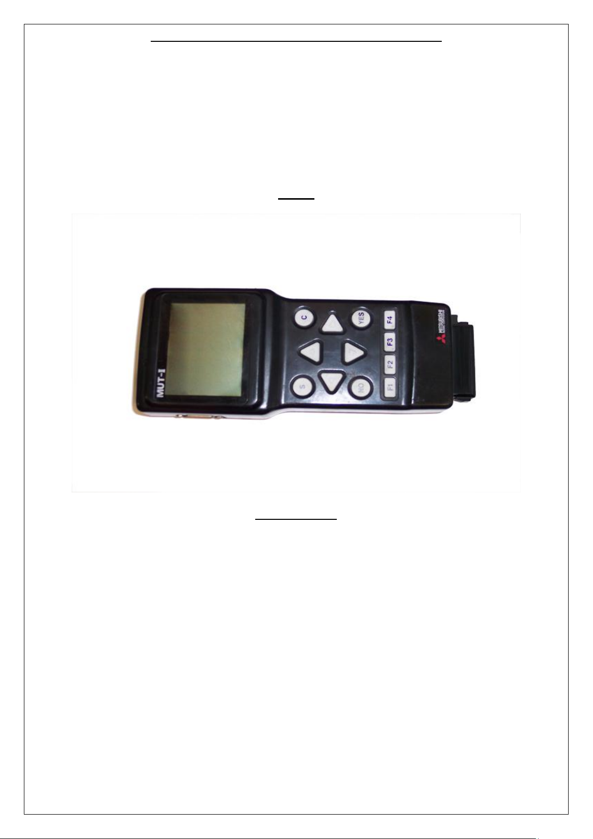
MUT-II
DESCRIPTION
The MUTII Tester is offered to the aftermarket in the same specification that is currently
supplied to MITSUBISHI franchised dealers. The MUTII can complete coverage all of
MITSUBISHI car systems past and present coupled with the knowledge that the
developments will continue well into the future .
Test function:
Read faulty code
Clear faulty code
Data stream
Activate state
Programming and coding control unit
Component test
Data stream
Page 2
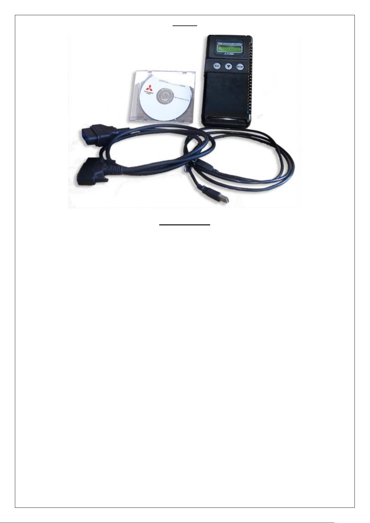
MUT III
DESCRIPTION
In accordance with releasing new products that introduce can communications systems,
mmc has developed the mut-iii as a next generation diagnosis tester for servicing these new
and future vehicles.
A personal computer (pc) is connected to the mut iii unit and used as a system¡¦s control
terminal, and communicates with a vehicle ecu through the v.c.i.. In addition to being able to
handle all diagnosis functions covered by the conventional mut-ii tester, the mut-iii system
can display data as easy-to-understand diagrams and graphs on a large screen of the pc.
Unlike the mut-ii, the mut-iii can retain data on all vehicles, from old to new models,
classified according to destination in the pc¡¦s hard disk. This eliminates the awkward but
essential job with the mut-ii, of switching the data list (communications protocol data and
diagnosis item list database) by replacing the rom pack with another according to the vehicle
model and year model.
New functions that make use of the advantages of the pc are also being developed. For
example, the workshop manual viewer is a useful function for mechanics as they no longer
have to carry around a thick manual and search for relevant pages while working on a
vehicle. The workshop manual viewer is currently available for certain vehicle models, and
allows users to retrieve the pages containing the failure code for a particular problem at the
push of a button.
Page 3

EVO SCAN
DESCRIPTION
To use evo scan You will require a potable pc, fto obd lead and evo scan software
Display and record engine data onto your PC at the highest speeds ever seen. High Speed
Data logging - 200 data items per second!
If your car has faulty sensors, and is displaying a Check Engine Light (CEL) on your
dashboard, you can use Evo Scan to read and identify Diagnostic Trouble Codes
(DTCs) You will be able to Read and Clear DTCs for heaps of protocols such as EvoX,
SST, ABS, AYC, ACD, SSMII, OBDII, EVOX CAN, OBDII
CAN.(SAE/ISO/KWP2000)
Record and Display air/fuel ratios and engine timing values on the colourful Map Tracer
Graph with pin point precision.
You can easily customise the gauges and layout to suit your own style and preferences.
Make your own awesome gauges using the easy built-in gauge designer.
Chart your vehicle data in real time or slice and dice the logs afterwards.
Page 4

ALTERNATIVE METHOD OF CODE READING
The first step is to remove the panel underneath
the steering wheel. This simply requires the
removal of four screws. Note that the bonnet
release cable and lever will still be connected to
this panel - just drop the panel down and keep it
out of the way.
Now if you crawl under there, you will notice an
interface socket on the left hand side, about level
with the bottom left screw you removed a moment
ago. You can click on the image (right) to
enlarge...
This is the location of the diagnosis connector and
where a MUT-II, MUT-III or EVO SCAN unit can be
connected.
The picture is oriented to the rear of the
vehicle. the strange circular thing in the centre
of the frame is simply the alarm's glass
breakage sensor.
As noted before, we must earth No. 1
terminal on this connector. The pin in
question is the bottom right one in the picture
- highlighted.
All we have to do is ground out this pin by
using a single cable. With the engine ignition
switch on, the computer will flash the engine
warning light to indicate any stored diagnostic
code(s).
At the back of the diagnostic plug, it was clear
to see that the relevant pin was connected to
an easily accessible lead (grey with red stripe)
on this 1995 GPX, but can be a different
colour on some other FTOs.
a standard patch connector was used to
attach an extra wire to the relevant lead (see
image to right, highlighted).
Now it is simply a matter of grounding out the
permanent diagnostic lead stowed under the
dash.
DISCLAIMER: DO NOT ATTEMPT ANY WIRING MODIFICATIONS YOURSELF WITHOUT (A)
CHECKING THE CONNECTIONS, WIRE COLOURS, ETC. ON YOUR OWN VEHICLE, AND (B)
KNOWING WHAT YOU ARE DOING. I TAKE NO RESPONSIBILITY FOR ANY COOKED WIRING,
ECUS OR ANYTHING ELSE YOU MAY FEEL LIKE PLAYING WITH. ANY WORK DONE ON YOUR
OWN VEHICLE IS DONE SO AT YOUR OWN RISK...
STEP 1
Earth No. 1 terminal (diagnostic control terminal) of the diagnostic connector.
STEP 2
Turn on the ignition switch.
Page 5

WHAT DOES THE ECU DIAGNOSTIC CODE LOOK LIKE WHEN IT IS
DISPLAYED?
The light you need to look at on the speedo cluster is the engine management warning light
shown below:
The light will flash in a sequence very similar to Morse code.
This diagnostic code 31would be shown by:;
blinking the engine warning light for 3 long flashes and 1 short flash.
If no codes are currently stored, it will simply flash continually, once per second.
I assume that if more than one code is stored, it will display each one in a repeating
sequence, eg. 31, 52, 64, 31, 52, 64...
To clear the codes, simply disconnect the car battery for 20 seconds or so.
Page 6

GEARBOX ECU CODE READING
NO
ENGINE CODE
NO
GEARBOX CODE
11
Oxygen Sensor
15
Oil temperature sensor
12
Air Flow Sensor
22
Input shaft speed sensor
13
Intake air temperature sensor
23
Output shaft speed sensor
14
Throttle position sensor
31
Low and reverse solenoid valve
15
ISC Motor Position Sensor
32
Under drive and reverse solenoid valve
21
Engine coolant temperature sensor
33
Second solenoid valve
22
Crank angle sensor
34
Overdrive solenoid valve
23
Camshaft position sensor
35
Reduction solenoid valve
24
Vehicle speed sensor
36
Damper clutch control solenoid valve
25
BARO Sensor
52
Damper clutch control solenoid valve
31
Detonation sensor
32
Vacuum sensor
36
Ignition Timing Adjustment Signal
39
Oxygen Sensor
41
Injector system
42
Fuel Pump
43
EGR
44
Ignition coil and power transistor unit
(Cylinder 1 & 4)
52
Ignition coil and power transistor unit
(Cylinder 2 & 5)
53
Ignition coil and power transistor unit
(Cylinder 3 & 6)
55
Idle Air Control Valve/Servo Valve
Position Sensor
61
Communications wire with A/T-ECU
62
Intake air control valve position sensor
64
Alternator FR terminal
71
Vacuum control solenoid valve (TCL)
72
Ventilation control solenoid valve (TCL)
For the tiptronic gear box codes watch the flashes of the 'N' on the dash board. The
first part of the code is represented by long flashes while the second part is
represented by short flashes. For example, if we take error code 23 (Output shaft
speed sensor), you would see 2 long flashes followed by 3 short ones.
COMMON ERROR CODES
 Loading...