

Mitsubishi Electric MS09EW, MS12EN, MU12EN, MUM18EW, MS15EN Parts Manual
...
SERVICE
&
PARTS
MANUAL
Wireless type
Models
INDOOR UNlT
MSOSEW
MS12EN
OUTDOOR UNlT
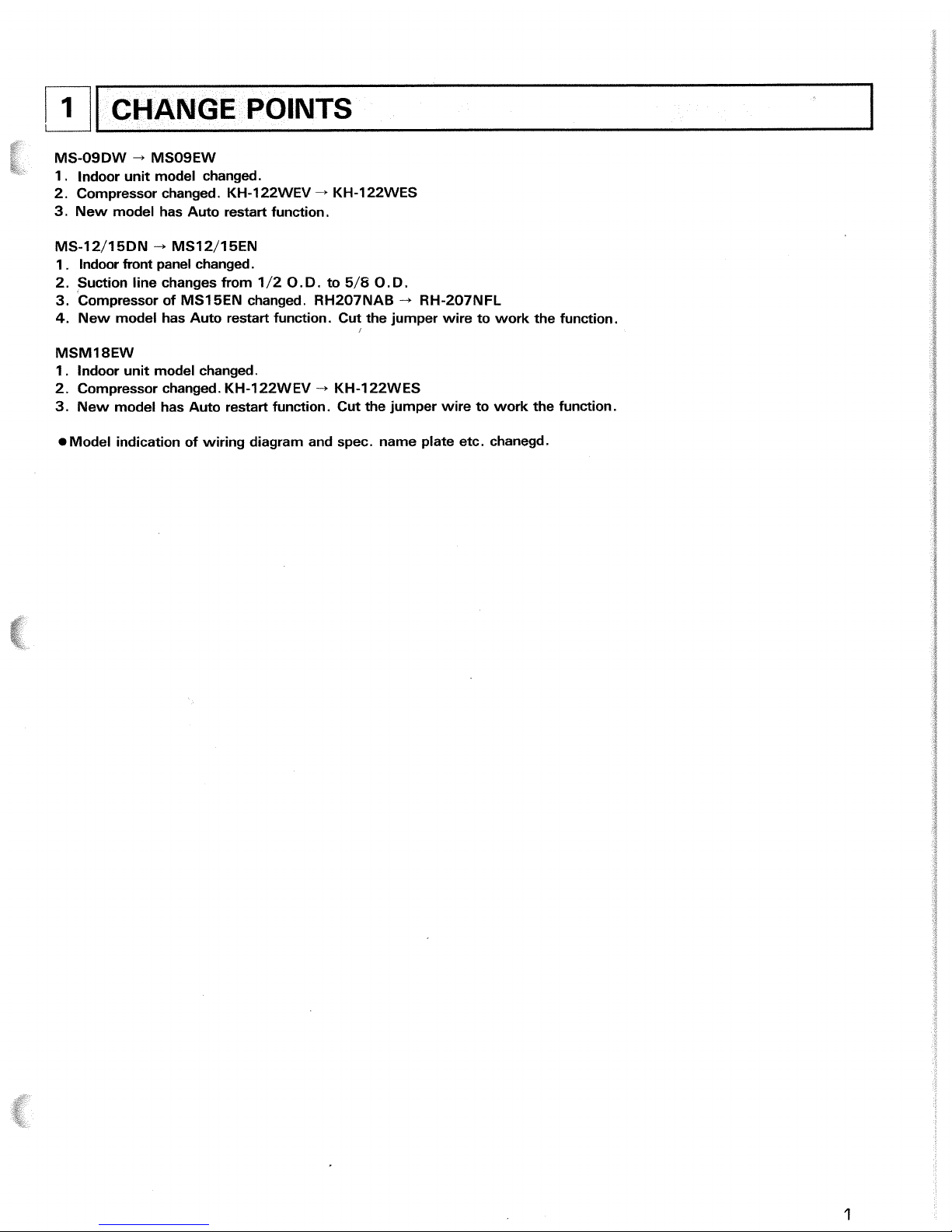
MS-O9DW + MSOSEW
1 . lndoor unit model changed.
2. Compressor changed. KH-122WEV
-+
KH-122WES
3.
New model has Auto restart function.
/
1
1
MS-12/15DN
-+
MS12/15EN
1
.
lndoor front panel changed.
2. Suction line changes from 1 /2
0.
D. to 5/8
0.
D
.
3.
Compressor of MS15EN changed. RH207NAB
-t
RH-207NFL
4.
New model has Auto restart function. Cut the jumper wire to work the function.
I
CHANGE
POINTS
MSMI 8EW
1
.
lndoor unit model changed.
2. Compressor changed. KH-122WEV
-.
KH-122W ES
3.
New model has Auto restart function. Cut the jumper wire to work the function.
Model indication of wiring diagram and spec. name plate etc. chanegd.
FEATURES
LCD wireless
remote controller
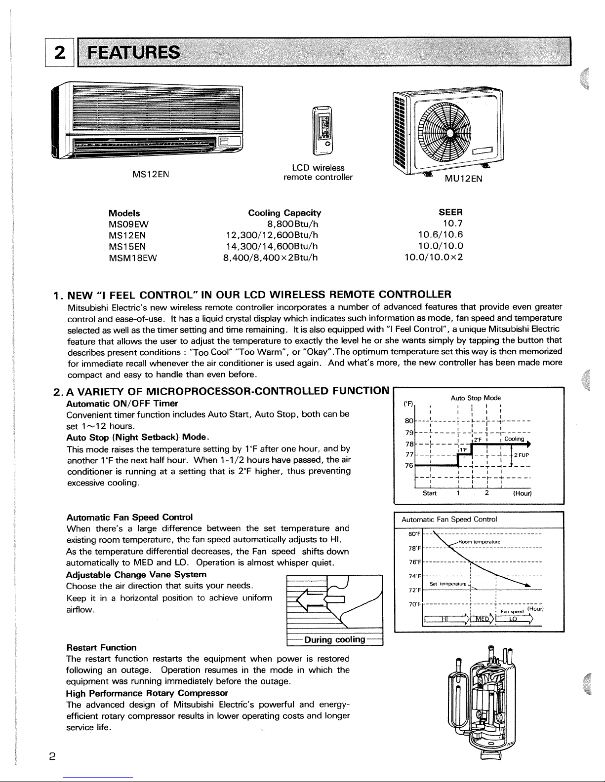
Models Cooling Capacity
MSOSEW 8,800 Btu/h
MS12EN 12,300/12,600Btu/h
MS15EN 14,300/14,600Btu/h
MSMI 8EW 8,400/8,400 x 2Btu/h
1.
NEW
"I
FEEL CONTROL" IN OUR LCD WIRELESS RER
SEER
10.7
10.6/10.6
10.0/10.0
10.0/10.0x2
dOTE CONTROLLER
Mitsubishi Electric's new wireless remote controller incorporates a number of advanced features that provide even greater
control and ease-of-use.
It
has a liquid crystal display which indicates such information as mode, fan speed and temperature
selected as well as the timer setting and time remaining.
It
is also equipped with
"I
Feel Control", a unique Mitsubishi Electric
feature that allows the user to adjust the temperature to exactly the level he or she wants simply by tapping the button that
describes present conditions
:
"Too Cool" "Too Warm", or "Okay" .The optimum temperature set this way is then memorized
for immediate recall whenever the air conditioner is used again. And what's more, the new controller has been made more
compact and easy to handle than even before.
2.
A VARIETY OF MICROPROCESSOR-CONTROLLED FUNCTION
Automatic ON/OFF Timer
Convenient timer function includes Auto Start, Auto Stop, both can be
set 1-12 hours.
Auto Stop (Night Setback) Mode.
This mode raises the temperature setting by 1 "F after one hour, and by
another 1
"F the next half hour. When 1-1 /2 hours have passed, the air
conditioner is running at a setting that is 2°F higher, thus preventing
excessive cooling.
Automatic Fan Speed Control
When there's a large difference between the set temperature and
existing room temperature, the fan speed automatically adjusts to HI.
As the temperature differential decreases, the Fan speed
shifts down
automatically to MED and LO.
Operation is almost whisper quiet.
Adjustable Change Vane System
Choose the air direction that suits your needs.
Keep it in a horizontal position to achieve uniform
aimow.
During cooling
Restart Function
The restart function restarts the equipment when power is restored
following an outage.
Operation resumes in the mode in which the
equipment was running immediately before the outage.
High Performance Rotary Compressor
The advanced design of Mitsubishi Electric's powerful and energy-
efficient rotary compressor results in lower operating costs and longer
service life.
76
I I
Start
1
2
(Hour)
1
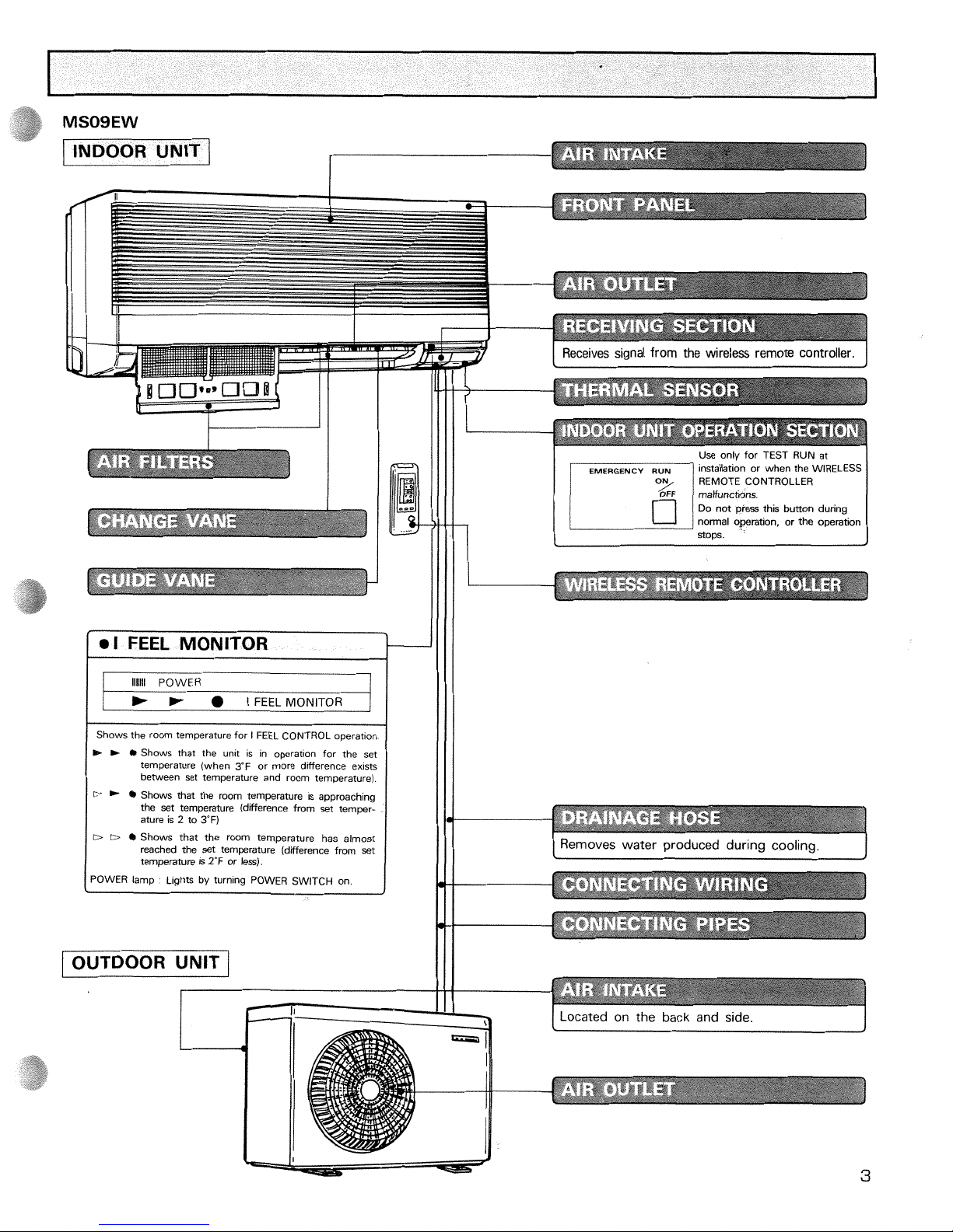
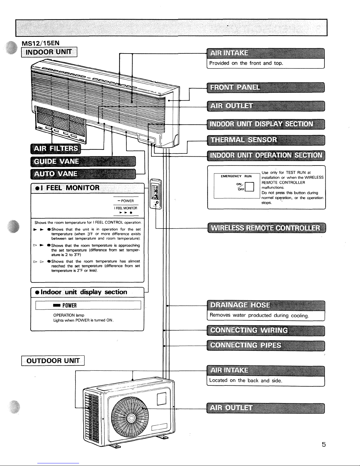
INDOOR UNIT
1
ll i 'ii
I
1
Shows the room temperature for I FEEL CONTROL
operation
R- R-
0
Shows that the unlt is in operation for the set
temperature (when 3'F or more difference exlsts
between set temperature and room temperature).
D
*
Shows that the room temperature
is
approaching
the set temperature (diierence from set temperature
is
2
to
3'F)
D
D
0
Shows that the room temperature has almost
reached the set temperature (difference from set
temperature
is
2°F or less).
I
POWER lamp
L~ghts by turning POWER SWITCH on
2
(
OUTDOOR UNIT
/
I
Receives signal from the wireless remote controller.
Use only for TEST RUN at
installation or when the WIRELESS
REMOTE CONTROLLER
maVunctlons
Do not press thls button dunng
normal
operanon,
or
the operahon
SODS.
Removes water produced during cooling.
J
I
Located on the back and side.
I
--
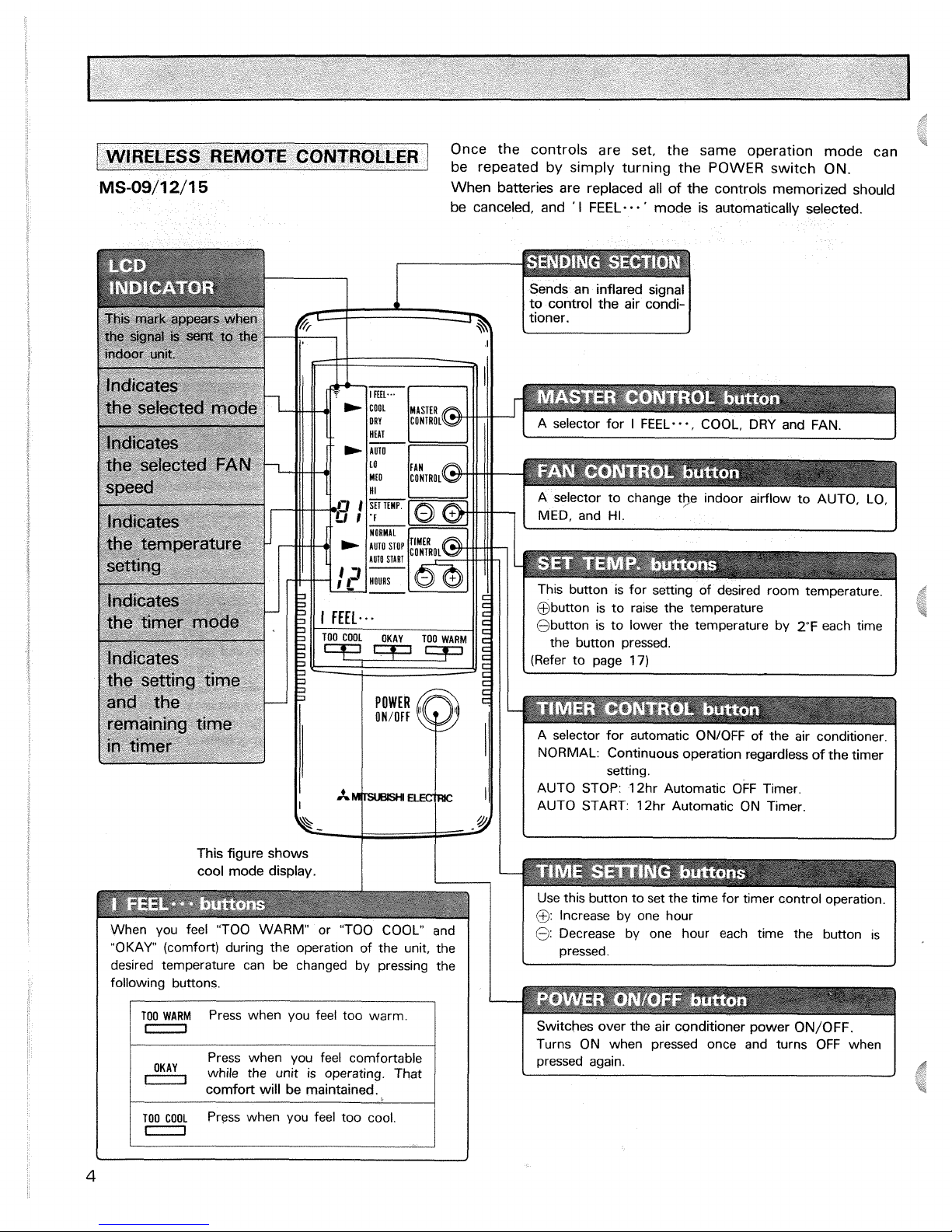
Once the controls are set, the same operatlon mode can
coNTRoLLE~
be repeated by s~mply turning the POWER sw~tch ON
-
--
When batteries are replaced all of the controls memorized should
be canceled, and
'
I
FEEL-.
-
'
mode is automatically selected.
Sends an inflared signal
to control the air
condi-
tioner.
1
This button is for setting of desired room temperature.
@button is to raise the temperature
@button is to lower the temperature by 2°F each time
the button pressed.
(Refer to page
17)
This figure shows
cool mode display.
When you feel "TOO WARM" or "TOO COOL" and
"OKAY (comfort) during the operation of the unit, the
desired temperature can be changed by pressing the
following buttons.
I
I
TO0
WARM
Press when you feel too warm.
0
while the unit is operating. That
-
comfort will be maintained.
TOO COOL
Press when you feel too cool.
I
in
A selector for automatic ON/OFF of the air conditioner.
NORMAL: Continuous operation regardless of the timer
setting.
AUTO STOP: 12hr Automatic OFF Timer.
AUTO START:
12hr Automatic ON Timer.
--
Switches over the air conditioner power ON/OFF.
Turns ON when pressed once and turns OFF when
pressed again.
Use this button to set the
tme for timer control operatlon
@
Increase by one hour
@
Decrease by one hour each tme the button is
pressed
I
INDOOR UNIT
]
A
Provided on the front and top.
I
FEEL
MONFTOR
/
Shows the room temperature for I FEEL CONTROL operatton
I
m
b
Shows that the unit is in operation for the set
temperature (when
3'F
or more difference exists
between set temperature and room temperature)
D
Shows that the room temperature k approaching
the set temperature (difference from set temperature
is
2
to
TF)
I
I
D D
Shows that the room temperature has almost
reached the set temperature (difference from set
temperature
is
2'F
or
less).
-
POWER
OPERATION lamp
Lights when POWER
is
turned ON.
I
OUTDOOR UNIT
]
Use only for TEST RUN at
REMOTE CONTROLLER
Do not
pres;
th~s button dunng
normal operabon, or the operation
stops
I
Removes water producted during
cool in^.
I
Located on the back and side.
I
-
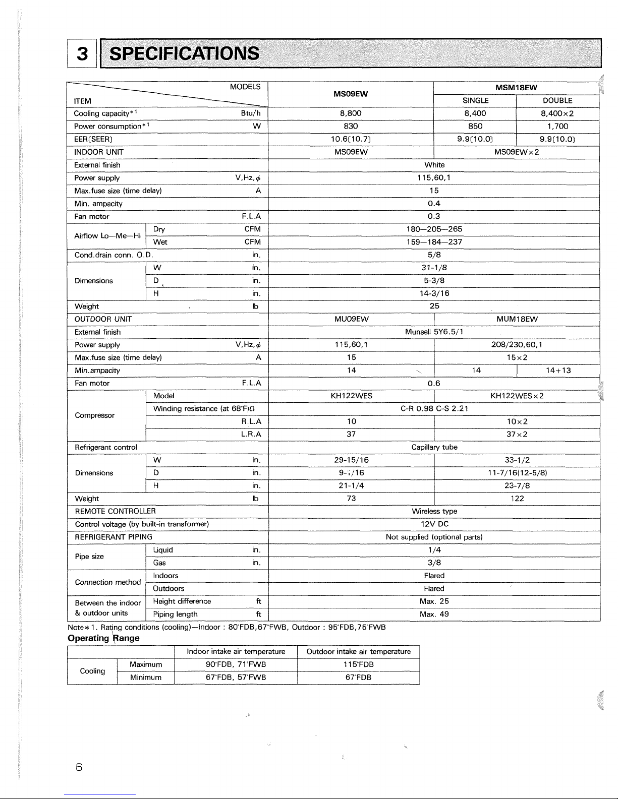
MODELS
ITEM
Cool~na cawacitv*
'
Btu/h
-.
,
I
I
I
/
power supply V.Hz,C
/
11 5,60, 1
1
MSOSEW
8.800
Power consumption*
'
W
/
830
EER[SEER)
INDOOR UNIT
External finish
/
Fan motor F.L.A
/
0.3
1
MSMISEW
850
10.6[10.7)
MSO9EW
Max.fuse size (time delay) A
/
15
SINGLE
1,700
Min. amoacity
I
Cond.drain conn. O.D. in.
1
5/8
1
DOUBLE
White
9.9(10.0)
0.4
Airflow Lo-Me-Hi
Dimensions
9.9[10.0)
IW
in.
I
31-11'8
I
8.400
MSO9EWx2
Dn/ CFM
8.400~2
180-205-265
/
H in.
1
14-3/16
I
Wet CFM
I
159-1 84-237
I
D ~n.
5-3/8
Weight Ib
I
25
/
Fan motor F.L.A
/
0.6
i-
OUTDOOR UNIT
External finish
Power supply V.Hz,C
Max.fuse size (time delay) A
I
1
/
Model KH 122WES KH 122WES x 2
MUOSEW
Munsell 5Y6.5/1
MUM18EW
11 5,60, 1
Compressor
/
REMOTE CONTROLLER
I
Wireless type
1
208/230,60,1
Winding resistance (at 68F)n
R.L.A
Refrigerant control
15
Capillary tube
Dimensions
Control voltage (by built-in transformer)
15x2
C-R 0.98 C-S 2.21
29-1 5/16
9-';/I 6
21-1/4
73
W in.
D
ln.
H in.
12V DC
Pipe size
10
33-1 /2
1 1-7/16(12-5/8)
23-7/8
122 Weight
Ib
Connection method
Note*
I.
Rating conditions (cooling)-Indoor : 8OFDB,67'FWB, Outdoor : 95FDB.75FWB
Operating kange
10x2
REFRIGERANT PIPING
Liquid in.
Gas in.
Between the indoor
&
outdoor units
I
/
Indoor intake air temwerature
I
Outdoor intake air temoerature
/
Not supplied (optional parts)
1 /4
3/8
Indoors
Height difference
ft
1
Max. 25
Piping length
ft
/
Max.
49
Flared
Outdoors
Cooling
Flared
SO'FDB, 71"FWB
67"FDB. 57"FWB
Maximum
Minimum
11 5FDB
67"FDB
I
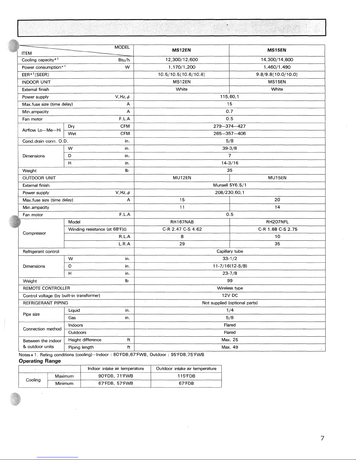
Cooling capacity*' Btu/h
/
12,300/12,600
/power consumption*
'
w
I
1,170/1,200
I
1,460/1,490
1
EER
*
'
(SEER)
I
I
/
Fan motor F.L.A
/
0.5
I
10.5/10.5(10.6/10.6)
External finish
Power supply V, Hz, 4
Max.fuse size (time delay) A
Min
.
ampacity A
9.8/9.8(10.0/10.0)
115,60,1
15
0.7
MS15EN
INDOOR UNIT
White
I
Dimensions
1
D in.
I
7
MS12EN
White
DW CFM
Cond.drain conn. O.D. in.
279-374-427
5/8
/W
in.
1
39-3/8
H
in.
Airflow Lo-Me-Hi
14-3/16
-
I
/
Max.fuse size (time delay) 15
1
20
1
Wet CFM
/
265-357-406
Weiqht Ib
/
35
OUTDOOR UNIT
External finish
Munsell 5Y6.5/1
MUl2EN
Power supply V,Hz,4
1
208/230,60,1
L.R.A
Refrigerant control
/W
in.
MU15EN
Dimensions
29
REMOTE CONTROLLER
Control voltage (by built-in transformer)
REFRIGERANT PIPING
35
D in.
H
in.
Wireless type
12V DC
Not supplied (optional parts)
Pipe size
Notes*
1. Rating conditions (cooling)-Indoor
:
80"FDBr67"FWB, Outdoor : 95FDB.75FWB
Capillary tube
33-1 /2
1 1-7/16(12-5/8)
23-7/8
Weight Ib
Connection method
Between the indoor
&
outdoor units
Operating Range
/
Indoor intake air temperature I Outdoor intake air temperature
1
99
Liquid in.
1 /4
Indoors
Outdoors
Height difference
ft
Piping length
ft
Gas in.
I
5/8
Flared
Flared
Max. 25
Max. 49
Cooling
SWFDB, 71"FWB
67"FDB. 57TWB
Maximum
Minimum
11 5FDB
67"FDB
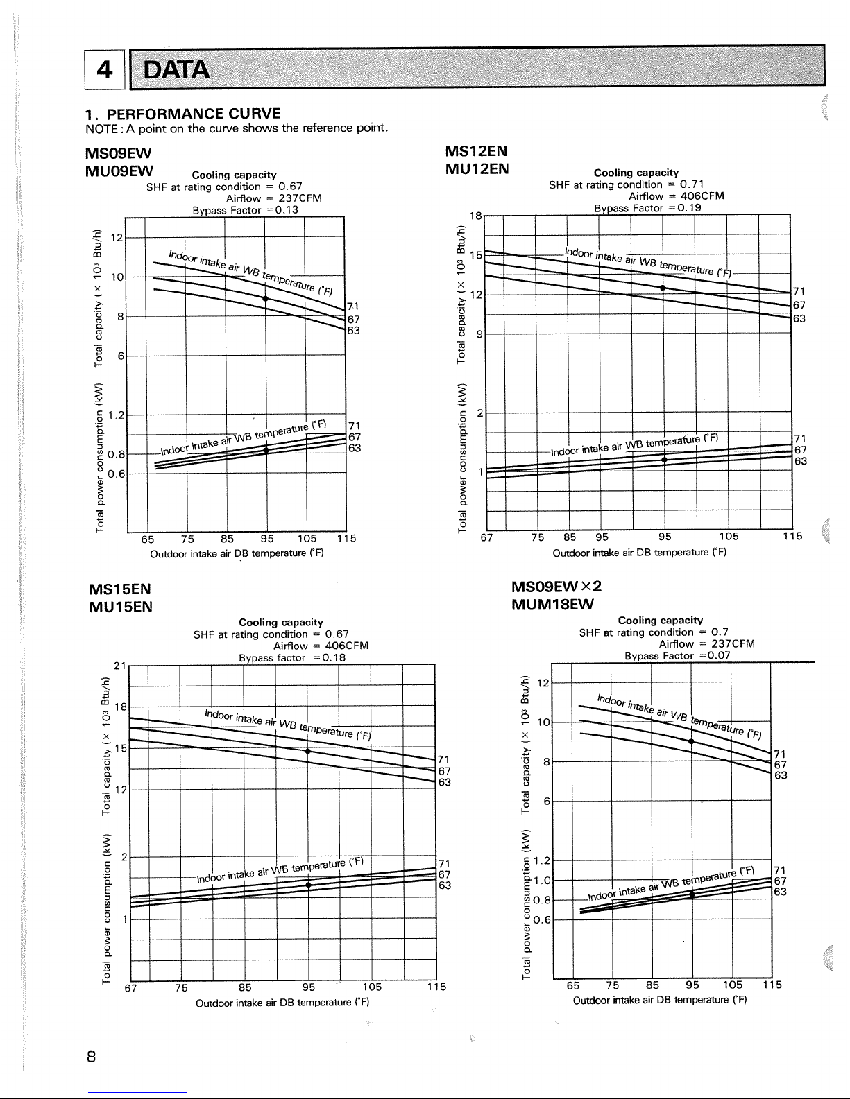
1. PERFORMANCE CURVE
NOTE
:
A
point on the
curve
shows
the
reference point.
1
Outdoor intake air DB temperature
rF)
DATA
MS15EN
MU15EN
Cooling capacity
SHF
at rating condition
=
0.67
Airflow
=
406CFM
MS12EN
MU12EN
Cooling capacity
SHF
at ratlng condition
=
0.7
1
Airflow
=
406CFM
18
e
i!
fj
15
Et
X
;
12 7 1
+
.-
0
67
m
a
63
5
9
-
m
C
2'
z
-
c
2
E!
C
e
7 1
2
67
63
81
k
3
a
-
m
C
I-
67 75 85 95 95 105 115
Outdoor intake air DB temperature
("F)
MSOSEW
x2
MUM18EW
Cooling capacity
SHF
st rating condition
=
0.7
Airflow
=
237CFM
Bypass Factor
=0.07
I
I
I
I
I I
I
Outdoor mtake air DB temperature
rF)
Outdoor ~ntake air DB temperature
("F)
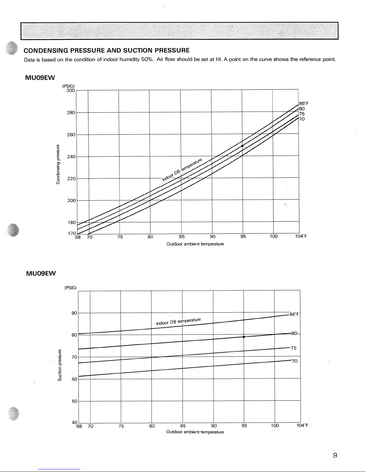
CONDENSING PRESSURE AND SUCTION PRESSURE
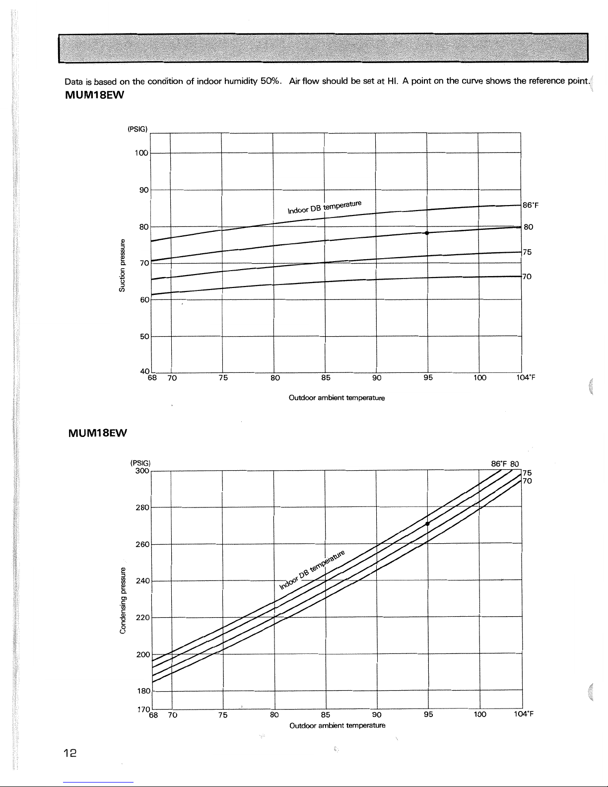
Data is based on the condition of indoor humidity
50%.
Air flow should be set at
Hi.
A point on the curve shows the reference point.
P!
I
,
P!
a
c
.-
I-'
3
m
85
90
95
100 1
Outdoor ambient temperature
Outdoor ambient temperature
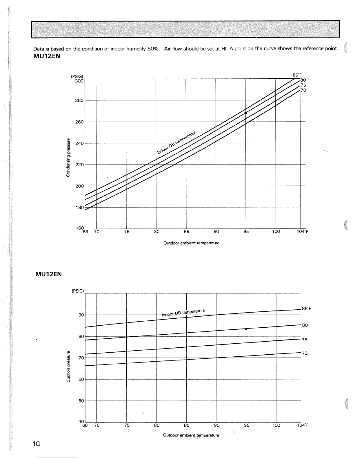
Data
is based on the condition of indoor humidity
50%.
Air flow should be set at
HI.
A point on the curve shows the reference point.
MU12EN
(PSIG)
Outdoor
ambient
temperature
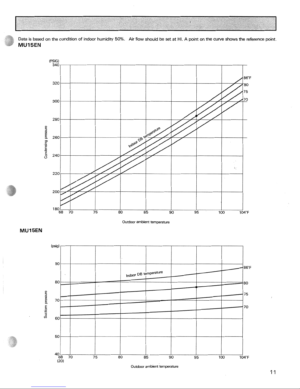
Data
is based on the condition of indoor humidity
50%.
Air flow should be set at
HI.
A point on the curve shows the reference point.
MUISEN
Outdoor ambient temperature
Data
is based on the condition of indoor humidity
50%.
Air flow should
be
set at
HI.
A
point on the curve shows the reference point.
(PSIG)
100
I
I I
I
0
85
90
95
100
Outdoor
ambient
temperature
Outdoor ambient temperature
Indoor unit MS12EN
I
MS15EN
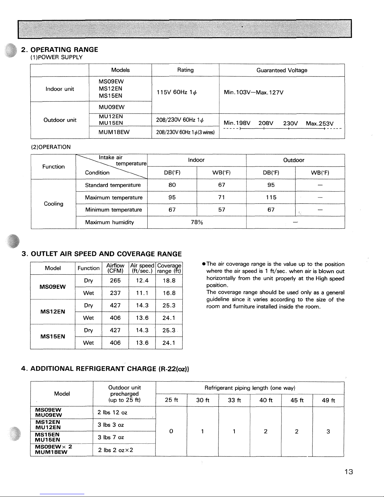
2. OPERATING RANGE
(1 )POWER SUPPLY
Min. l03V-Max. 127V
Models
Rating
Outdoor unit
Guaranteed Voltage
MUM1 8EW
Function
Min. 198V 208V 230V Max.253V
MU
12EN
MU1
5EN
2081230V 60Hz
1
d(3
wires)
Standard temperature
Maximum
tern~erature
2081230V 60Hz 14
-----
Cooling
3.
OUTLET AIR SPEED AND COVERAGE RANGE
Outdoor
DB("F)
i
WB("F)
Indoor
80
9
5
I
Maximum humidity
Model
Airflow Air speed Covera e
I I
(CFM) I ift/sec.) I ranae
I
DB("F)
I
I
I I
MSOSEW
14.3 25.3
MSl SEN
Wet 406 13.6 24.1
WB("F)
67
7
1
78%
4.
ADDITIONAL REFRIGERANT CHARGE (R-22(oz))
Minimum temperature
-
*The air coverage range is the value up to the position
where the air speed is 1 ft/sec. when air is blown out
horizontally from the unit properly at the High speed
position.
The coverage range should be used only as a general
guideline since
it
varies according to the size of the
room and furniture installed inside the room.
9 5
115
5 7 67
Model
-
-
67
-
Outdoor unit
precharged
(up to 25
ft)
I
I
I
I
I
I
I
/
3 lbs 7 oz
Refrigerant piping length (one way)
MSOSEW
MUOSEW
MS12EN
MU12EN
25 ft
2 Ibs
12
oz
3
Ibs 3 oz
30 ft
49 ft
33 ft 40 ft
45 ft
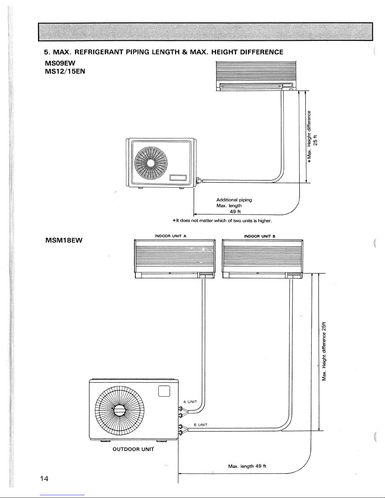
5.
MAX.
REFRIGERANT PIPING LENGTH & MAX.
HEIGHT DIFFERENCE
Additional piping
Max.
length
r
49
ft
*Jt
does not
matter
which
of
two units
is
higher.
INDOOR UNIT
A
INDOOR UNIT
I3
OUTDOOR UNlT
-
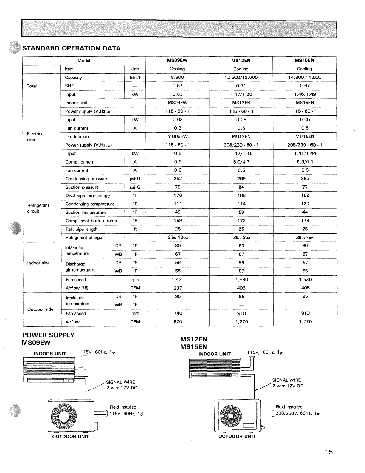
TANDARD OPERATION DATA
I
[tern
/
Unit
1
Cooling
1
Cooling
I
Cooling
I
Model
MSOSEW MSl
PEN
Total
MSl
BEN
Input
Capacity
SHF
Power supply (V,Hz,+)
kW
Electrical
circuit
I
Fan current
IAl
0.6
1
0.5
I
0.5
1
Btu/h
-
/
Indoor unit
115.60.1
Input
0.83
Input
I
kW
/
0.03 0.05
Fan current
/
Discharge temperature
I
%
I
176
1
188
I
182
I
8,800
0.67
MSO9EW
115.60.1
0.05
Power supply (V,Hz,d)
k W
Condensing pressure
Suction pressure
1.17/1.20
115-60.1
A
12,300/12,600
0.71
1.46/1.49
MSl2EN
Outdoor unit
115.60.1
0.8
6.5/6.1
Comp. current
/
A
/
6.6
psi.G
psi-G
Refrigerant
circuit
/
Refrigerant charge
1-1
2ibs 120z
1
31bs 30z
1
31bs 70z
I
14,300/14,600
0.67
MS1 SEN
0.3
5.0/4.7
Comp. shell bottom temp.
Ref. pipe length
MUO9EW
208/230.60
-
1
1.12/1.15
252
79
Condensing temperature
Suction temperature
indoor side Discharge
air temperature
208/230.60
1
0.5
1.41/1.44
"F
ft
/
Fan speed
/
rpm
I
1,430
1
1,530
I
1,530
I
0.5
MU12EN
ppp
269
84
"F
'F
Intake air
temperature
MU1 SEN
285
77
159
25
"F
'F
DB
WB
/
Airflow
I
CFM
/
920
I
1,270
I
1,270
1
111
49
Outdoor side
POWER SUPPLY
MSOSEW
172
25
80
67
INDOOR UNlT
60Hz,
'4
n
n
II
1 14
59
173
25
SIGNAL
WIRE
2 wire 12V DC
120
44
80
67
Airflow (Hi)
Field installed
1
15V 60Hz, 14
80
67
CFM
"F
"F
rpm
Intake air
temperature
MS12EN
MS15EN
INDOOR UNlT
11 5V. 60Hz. 1 4
DB
WB
SIGNAL
WlRE
237
95
-
740
Fan speed
It'
2 wire 12V DC
OUTDOOR UNlT
406
95
-
910
OUTDOOR UNlT
406
95
-
910
 Loading...